

Form No. 3365-751 Rev. A
POWERVAC
™
Model No. 51984—310000001 & Up
If you have questions concerning
your blower, please call us
at 1-866-574-9242 (US) or
1-866-574-9243 (Canada).
WARNING:
To reduce the risk of injury, the user must read and understand the Operator’s Manual. Save this manual.
English (EN), French (FR), and Spanish (ES)
READ THIS INFORMATION
Before you use your new Powervac™, read the following helpful hints to
get you started.
Fueling
WARNING:
Gasoline and its vapors are highly ammable and
explosive. To prevent serious personal injury and
property damage, handle it with care. Keep away
from ignition sources and open ames, handle
outdoors only, do not smoke and wipe up spills
immediately.
1. Obtain a clean container that is approved for use with gasoline.
2. Mix all of the 2-cycle oil provided with 1 US gallon of 87-octane, unleaded
gasoline (50:1).
3. Fill the blower’s fuel tank carefully.
Cold Starting vs. Warm Starting
When you restart the blower and you are not sure whether the engine is still warm, set the choke
lever to RUN, lock the throttle wide open, and pull the recoil starter grip. If the engine does not start
within 5 pulls, refer to “To Start a Cold Engine” later in this manual.
Flooded Engine
If the engine does not start, it may be ooded. Relax, this is easy to correct. Set the choke lever to
RUN. Lock the throttle wide open and pull the recoil starter grip quickly for 10 to 12 pulls.
If the engine still does not start, refer to “Troubleshooting” later in this manual.
For questions concerning your blower,
call us toll free at 1-866-574-9242 (US) or
CALL
1-866-574-9242 (US) or
1-866-574-9243 (Canada)
1-866-574-9243 (Canada).
WARNING: The engine exhaust from this product contains chemicals known to the State
of California to cause cancer, birth defects or other reproductive harm.
CALIFORNIA PROPOSITION 65
2

TABLE OF CONTENTS
Introduction ...................................................................................................................................................................................4
General Safety Rules .....................................................................................................................................................................5
Specic Safety Rules ....................................................................................................................................................................6
Symbols.........................................................................................................................................................................................7
Product Labels ..............................................................................................................................................................................8
Features ................................................................................................................................................................................... 9-10
Product Specications ...........................................................................................................................................................9
Assembly................................................................................................................................................................................11-13
Unpacking ............................................................................................................................................................................ 11
Assembling The Blower Tubes ............................................................................................................................................ 11
Grounding Instructions ........................................................................................................................................................ 11
Installing the Vacuum Handle .............................................................................................................................................. 12
Installing the Vacuum Bag ................................................................................................................................................... 12
Installing the Vacuum Tubes .......................................................................................................................................... 12-13
Operation ............................................................................................................................................................................... 14-17
Applications .........................................................................................................................................................................14
Mixing Fuel .........................................................................................................................................................................14
Filling the Tank ....................................................................................................................................................................14
Oxygenated Fuels ................................................................................................................................................................14
Starting and Stopping ..........................................................................................................................................................15
Operating the Blower ..................................................................................................................................................... 15-16
Throttle Lock ................................................................................................................................................................. 16-17
Vacuum Operation ...............................................................................................................................................................17
Maintenance .......................................................................................................................................................................... 18-21
General Maintenance ...........................................................................................................................................................18
Replacing and Cleaning the Air Filter .................................................................................................................................18
Cleaning the Exhaust Port, Mufer and Spark Arrestor ......................................................................................................19
Vacuum Bag .........................................................................................................................................................................19
Fuel Cap ...............................................................................................................................................................................19
Spark Plug Replacement ......................................................................................................................................................20
Storing the Product ..............................................................................................................................................................20
Emissions Maintenance Schedule ........................................................................................................................................20
High Altitude Engine Operation ..........................................................................................................................................21
Troubleshooting ..........................................................................................................................................................................21
Warranty ................................................................................................................................................................................ 22-24
Table of Contents
3
INTRODUCTION
Thank you for purchasing a Toro product.
We would like for you to be completely satised with your new product, so feel free to contact an authorized service dealer
for help with service, genuine Toro parts, or other information you may require.
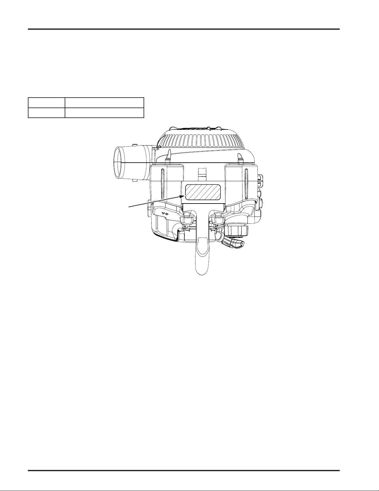
Whenever you contact an authorized service dealer, always know the model and serial numbers of the product. These numbers will help the service representative provide exact information about your specic product. You will nd the model and
serial number data label located on the bottom of the housing.
For your convenience, write the product model and serial numbers in the space below.
Model No.
Serial No.
Data
Label
Read this manual carefully to learn how to operate and maintain your product correctly. Reading this manual will help you
and others avoid personal injury and damage to the product. Although Toro designs, produces, and markets safe, state-of-the-
art products, you are responsible for using the product properly and safely. You are also responsible for training persons you
allow to use the product about safe operation.
The Toro warning system in this manual identies potential hazards and has special safety messages that help you and others
avoid personal injury, even death. DANGER, WARNING, and CAUTION are signal words that identify the level of hazard.
However, regardless of the hazard, be extremely careful. Two other words, “Important” and “Note,” highlight information.
4
Introduction

GENERAL SAFETY RULES
WARNING:
Read and understand all instructions. Failure to follow all instructions listed below may result in electric
shock, re and/or carbon monoxide poisoning which will cause death or serious personal injury.
Do not allow children or untrained individuals to use this
unit.
Never start or run the engine inside a closed area; breath-
ing exhaust fumes can kill.
Always wear eye protection with side shields marked to
comply with ANSI Z87.1, along with hearing protection.
Failure to do so could result in objects being thrown into
your eyes and other possible serious injuries.
Keep all bystanders, children, and pets at least 50 feet
away.
Wear heavy long pants, long sleeves, boots, and gloves.
Do not wear loose-tting clothing, short pants, sandals,
jewelry of any kind, or go barefoot.
To reduce the risk of injury associated with objects being
drawn into rotating parts, do not wear loose clothing,
scarves, neck chains, and the like. Secure long hair so it
is above shoulder level to prevent entanglement in any
rotating parts.
Do not operate this unit when you are tired, ill, or under
the inuence of alcohol, drugs, or medication.
Do not operate in poor lighting.
Keep all parts of your body away from any moving parts
and all hot surfaces of the unit.
Wear a face lter mask in dusty conditions to reduce the
risk of injury associated with the inhalation of dust.
Check the work area before each use. Remove all objects
such as rocks, broken glass, nails, wire, or string which
can be thrown or become entangled in the machine.
Keep rm footing and balance. Do not overreach. Over-
reaching can result in loss of balance or exposure to hot
surfaces.
Never operate the unit without a spark arrestor screen;
this screen is located inside the mufer.
Product users on United States Forest Service land, and
in some states, must comply with re prevention regulations. This product is equipped with a spark arrestor;
however, other user requirements may apply. Check with
the federal, state, or local authorities in your area.
Before storing, allow the engine to cool.
Use only Toro replacement parts and accessories. Failure
to do so may cause poor performance or possible injury.
Maintain the unit per maintenance instructions in this
operator’s manual.
Inspect the unit before each use for loose fasteners, fuel
leaks, etc. Replace damaged parts.
Do not use on a ladder, rooftop, tree, or other unstable
support. Stable footing on a solid surface enables better
control of the Powervac™ in unexpected situations.
SERVICE
Before cleaning, repairing, or inspecting, shut off the
engine and make certain all moving parts have stopped.
Disconnect the spark plug wire, and keep the wire away
from the plug to prevent starting.
Service on the Powervac™ must be performed by
qualied repair personnel only. Service or maintenance
performed by unqualied personnel could result in injury
to the user or damage to the product.
Use only identical replacement parts when servicing the
Powervac™. Use of unauthorized parts may create a risk
of serious injury to the user, or damage to the product.
General Safety Rules
5

SPECIFIC SAFETY RULES
Always hold the blower in your right hand during blower
operation. Refer to the OPERATION instructions later in
this manual for proper position during vacuum operation
and additional information.
To reduce the risk of hearing loss associated with sound
level(s), hearing protection is required.
To reduce the risk of injury associated with contacting
rotating parts, stop the engine before installing or removing attachments. Always disconnect the spark plug before
performing maintenance or accessing any movable parts.
Do not point the blower nozzle in the direction of people
or pets.
Never run the unit as a blower without the blower tubes
installed.
Never place objects inside the blower tubes.
Use only as directed in this operator’s manual.
Do not operate vacuum without vacuum bag installed;
ying debris could cause serious injury. Always close
vacuum bag completely before operating.
Rotating impeller blades can cause severe injury. Stop
the engine and ensure impeller blades have stopped
rotating before opening the vacuum door or installing/
changing tubes. Do not put hands or any other object into
the vacuum tubes while they are installed on the unit.
Never run the unit without the proper equipment at-
tached. When used as a blower, always install the
blower tubes. When used as a vacuum, always install the
vacuum tubes and vacuum bag. Make sure the vacuum
bag is completely zipped when the unit is running to
avoid ying debris.
Avoid situations that could catch the vacuum bag on
re. Do not operate near an open ame. Do not vacuum
warm ash from replaces, barbecue pits, brush piles, etc.
Do not vacuum discarded cigars or cigarettes unless the
cinders are completely cool.
FUELING
Fuel is highly ammable. Take precautions when using
to reduce the chance of serious personal injury.
Store fuel in a cool, well-ventilated area, safely away
from spark and/or ame-producing equipment.
Store fuel in containers specically designed for this
purpose.
Only refuel outdoors and do not smoke while refueling.
Add fuel before starting the engine. Never remove
the cap of the fuel tank or add fuel while the engine is
running or when the engine is hot.
Do not smoke while handling fuel.
Mix and store fuel in a container approved for gasoline.
Mix fuel outdoors where there are no sparks or ames.
Loosen fuel cap slowly to release pressure and to keep
fuel from escaping around the cap.
Tighten the fuel cap securely after refueling.
Wipe spilled fuel from the unit. Move 30 feet away from
refueling site before starting engine.
Never attempt to burn off spilled fuel under any circum-
stances.
To reduce the risk of re and burn injury, handle fuel
with care. It is highly ammable.
If fuel is spilled, do not attempt to start the engine but
move the machine away from the area of spillage and
avoid creating any source of ignition until fuel vapors
have dissipated.
Replace all fuel tank and container caps securely.
Empty fuel tank into a container approved for gasoline
and restrain the unit from moving before transporting in
a vehicle.
When draining the fuel tank, use an approved fuel stor-
age container in a well-ventilated area.
Select bare ground, stop engine, and allow to cool before
refueling.
Save these instructions. Refer to them frequently and use
them to instruct others who may use this tool. If you loan
someone this tool, loan them these instructions also.
6
Specific Safety Rules
SYMBOLS
The following signal words and meanings are intended to explain the levels of risk associated with this
product.
SYMBOL SIGNAL MEANING
DANGER: Indicates an imminently hazardous situation, which, if not avoided, will
result in death or serious injury.
WARNING: Indicates a potentially hazardous situation, which, if not avoided, could
result in death or serious injury.
CAUTION: Indicates a potentially hazardous situation, which, if not avoided, may
result in minor or moderate injury.
CAUTION: (Without Safety Alert Symbol) Indicates a situation that may result in
property damage.
Some of the following symbols may be used on this product. Please study them and learn their meaning for safe
operation of this product.
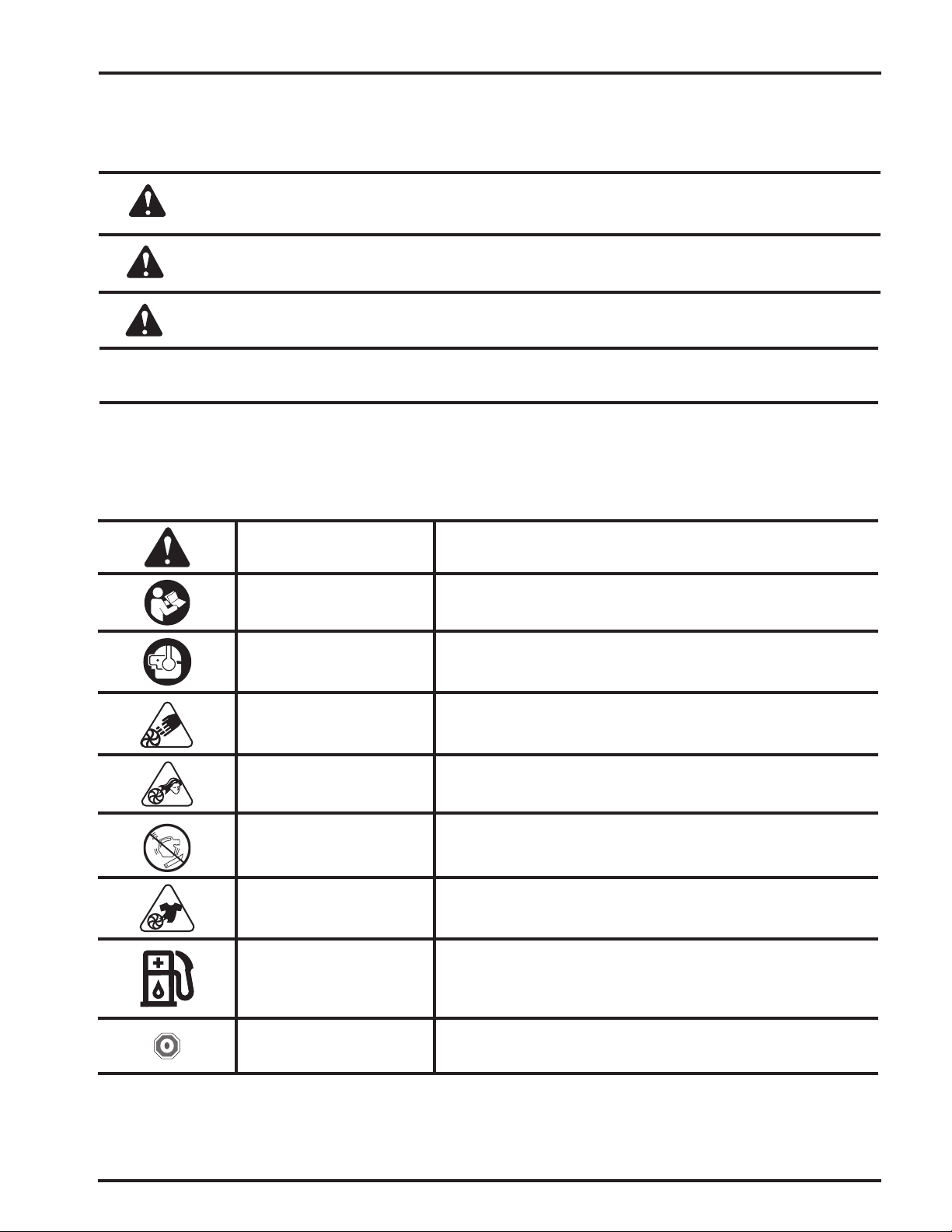
SYMBOL NAME EXPLANATION
Safety Alert Symbol Indicates a potential personal injury hazard.
Read Operator’s Manual
Wear Eye and Hearing
Protection
Vacuum Door Do not run unit while vacuum door is unsecured.
Long Hair Risk of long hair being drawn into air inlet.
Blower Tubes Do not run unit without tubes in place.
Loose Clothing Risk of loose clothing being drawn into air intake.
Gasoline and Lubricant
To reduce the risk of injury, user must read and understand opera-
tor’s manual before using this product.
Always wear eye protection with side shields marked to comply
with ANSI Z87.1 as well as hearing protection when operating this
equipment.
Use unleaded gasoline intended for motor vehicle use with an oc-
tane rating of 87 [(R + M) / 2] or higher. This product is powered
by a 2-cycle engine and requires pre-mixing gasoline and 2-cycle
lubricant.
Symbols
Stop symbol
To stop the engine, press and hold the stop switch in the stop
position
7
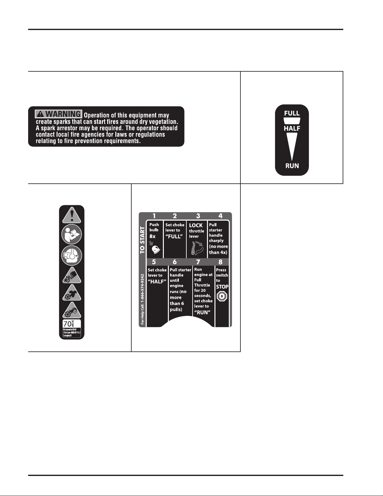
PRODUCT LABELS
®
®
Product labels and instructions are easily visible to the operator and are located near any area of potential danger.
Replace damaged or lost labels.
Part No. 940835003Part No. 940654088
Part No. 940927001 Part No. 940908001
8
Product Labels
FEATURES
Product Specifications
Name Specification
Weight 9.7 lbs (4.4 kg)
Engine 25.4 cc Full Crank
Air Velocity
MPH Up to 160 (257.5 kph)
CFM Up to 420 (11.89 m3/min)
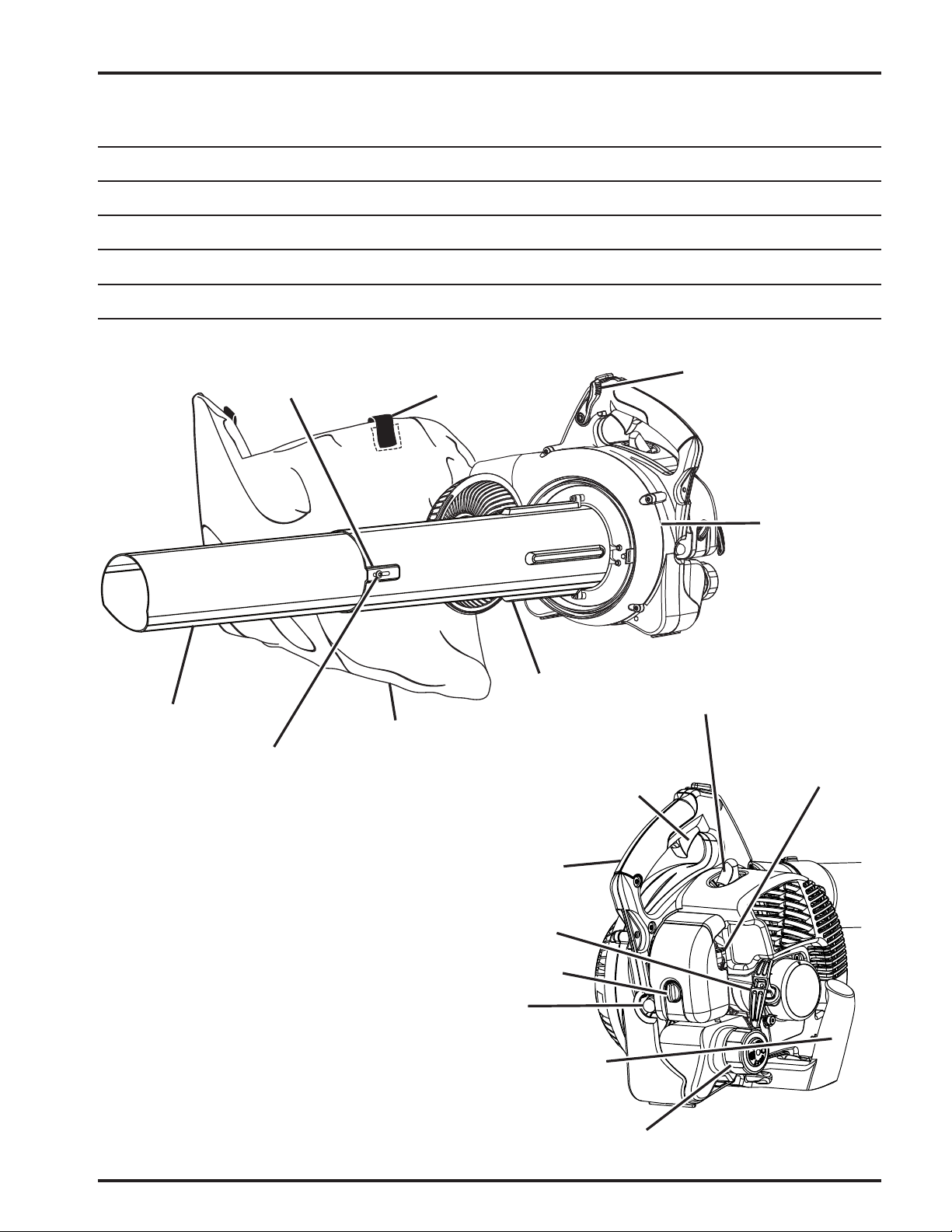
RAISED SLOT
VACUUM BAG
SHOULDER STRAP
THROTTLE
LOCK
LOWER VACUUM
TUBE
VACUUM TUBE
SCREW
VACUUM BAG
UPPER VACUUM
TUBE
UPPER HANDLE
STARTER GRIP
AND ROPE
AIR FILTER
COVER KNOB
THROTTLE
TRIGGER
MAIN
HOUSING
SPARK PLUG
CHOKE LEVER
Features
PRIMER BULB
VACUUM HANDLE
FUEL CAP
Figure 1
9
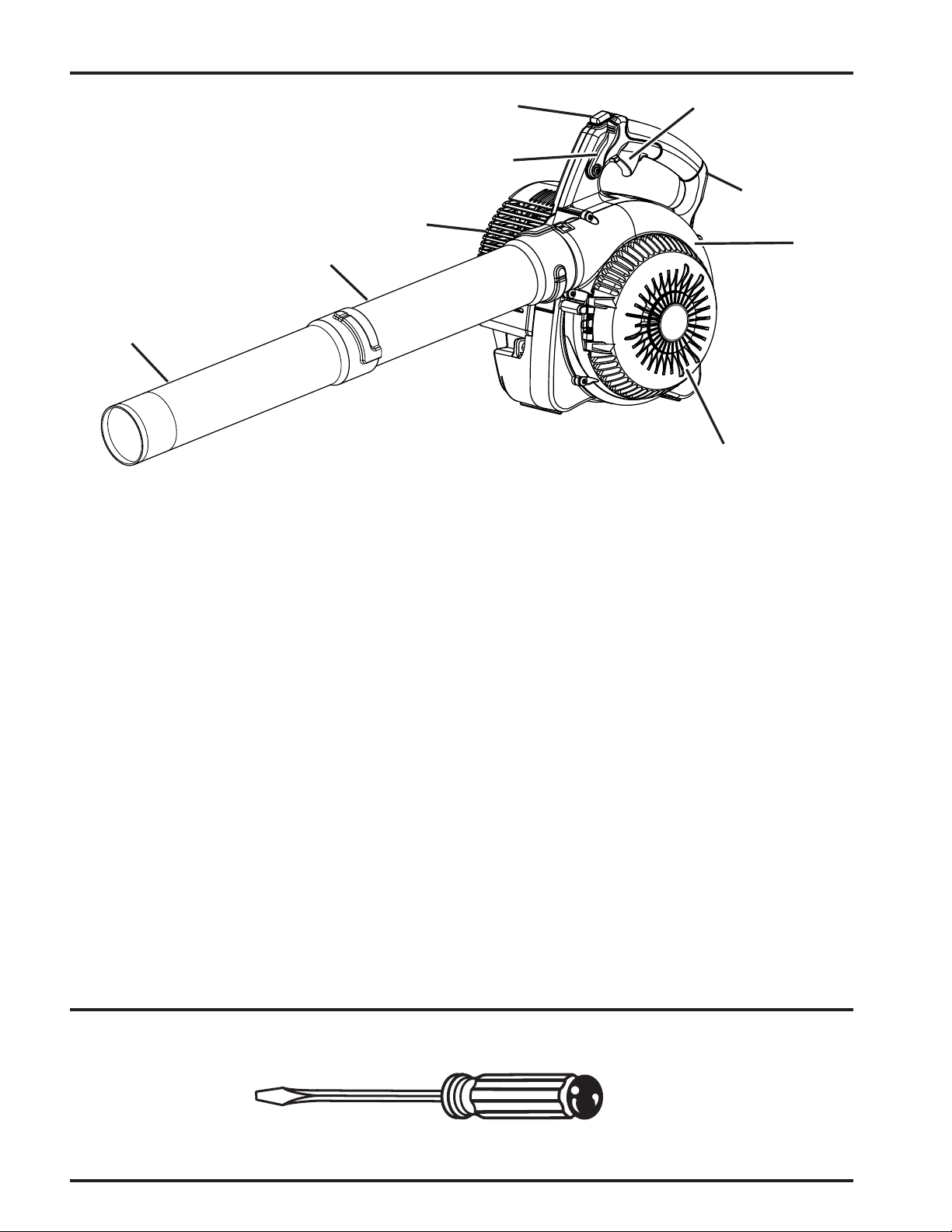
FEATURES
STOP SWITCH
MUFFLER
UPPER BLOWER TUBE
SWEEPER NOZZLE
KNOW YOUR BLOWER / VACUUM
See Figures 1-2.
The safe use of this product requires an understanding of the
information on the tool and in this operator’s manual as well
as a knowledge of the project you are attempting. Before
use of this product, familiarize yourself with all operating
features and safety rules.
BLOWER TUBE AND NOZZLE
The blower tubes can be assembled and installed on the
main housing using no tools.
THROTTLE LOCK
The throttle lock feature allows the user to operate the
blower without holding the throttle trigger. To slow the
engine speed, simply push the throttle lock forward.
ENGINE
The blower has a powerful 25.4cc engine with sufcient
power to handle tough blowing and vacuuming jobs.
MULCHER
The blower is equipped with a metal mulching blade that
efciently reduces leaves at a 10:1 ratio.
THROTTLE TRIGGER
THROTTLE
LOCK
UPPER HANDLE
MAIN
HOUSING
VACUUM INLET
DOOR
Figure 2
SWEEPER NOZZLE
The sweeper nozzle allows for more area to be covered during blower operation.
THROTTLE TRIGGER
The blower can be operated at any speed between idle and
full throttle.
VACUUM/MULCHER
Converting the blower to a vacuum/mulcher is simple and
can be done using a straight screwdriver.
VACUUM BAG
The vacuum bag attaches to the main housing easily by using the vacuum bag adaptor.
VACUUM HANDLE
This feature allows user to perform vacuuming duties com-
fortably.
VACUUM TUBES
The vacuum tubes can be installed on the main housing using a at head screw driver.
TOOLS NEEDED
The following tool (not included or drawn to scale) is needed for assembly:
STRAIGHT SCREWDRIVER
10
Features
ASSEMBLY
Unpacking
This product requires assembly.
Carefully remove the product and any accessories from
the box. Make sure that all items listed in the packing
list are included.
WARNING:
Do not use this product if any parts on the Pack-
ing List are already assembled to your product
when you unpack it. Parts on this list are not as-
sembled to the product by the manufacturer and
require customer installation. Use of a product
that may have been improperly assembled could
result in serious personal injury.
WARNING:
Do not attempt to modify this product or create
accessories not recommended for use with this
product. Any such alteration or modication is
misuse and could result in a hazardous condition
leading to possible serious personal injury.
WARNING:
To prevent accidental starting that could cause
serious personal injury, always disconnect the
engine spark plug wire from the spark plug
when assembling parts.
Inspect the product carefully to make sure no breakage
or damage occurred during shipping.
Do not discard the packing material until you have
carefully inspected and satisfactorily operated the
product.
If any parts are damaged or missing, please call
1-866-574-9242 (US) or 1-866-574-9243 (Canada) for
assistance.
Packing List
Blower
Grounding Wire
Upper Blower Tube
Sweeper Nozzle
Vacuum Handle
Vacuum Handle Knobs (2)
Upper and Lower Vacuum Tubes
Vacuum Tube Screws (2)
Vacuum Bag Assembly
Vacuum Bag Adaptor
2-Cycle Engine Lubricant
Operator’s Manual
NOTE: Read and remove all hang tags and store with your
operator’s manual.
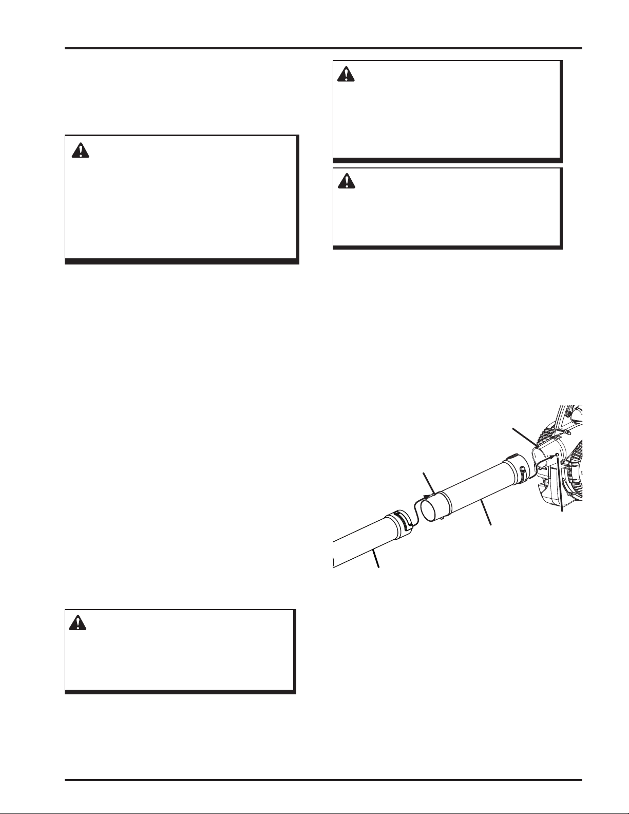
ASSEMBLING THE BLOWER TUBES
See Figure 3.
1. Align raised tabs on main housing to the slots on upper
tube; slide together and tighten securely by twisting.
Check tightness after initial run and retighten if needed.
2. Secure the sweeper nozzle and upper blower tube
together by aligning the raised locking tab on the upper
blower tube with the raised slot on the sweeper nozzle.
3. To disassemble, rotate the tube and nozzle to unlock
them and remove from the main housing outlet.
MAIN HOUSING
OUTLET
RAISED
LOCKING
TAB
RAISED
UPPER BLOWER
TUBE
SWEEPER
NOZZLE
LOCKING
TAB
Figure 3
WARNING:
If any parts are damaged or missing do not
operate this product until the parts are replaced.
Use of this product with damaged or missing
parts could result in serious personal injury.
Assembly
11
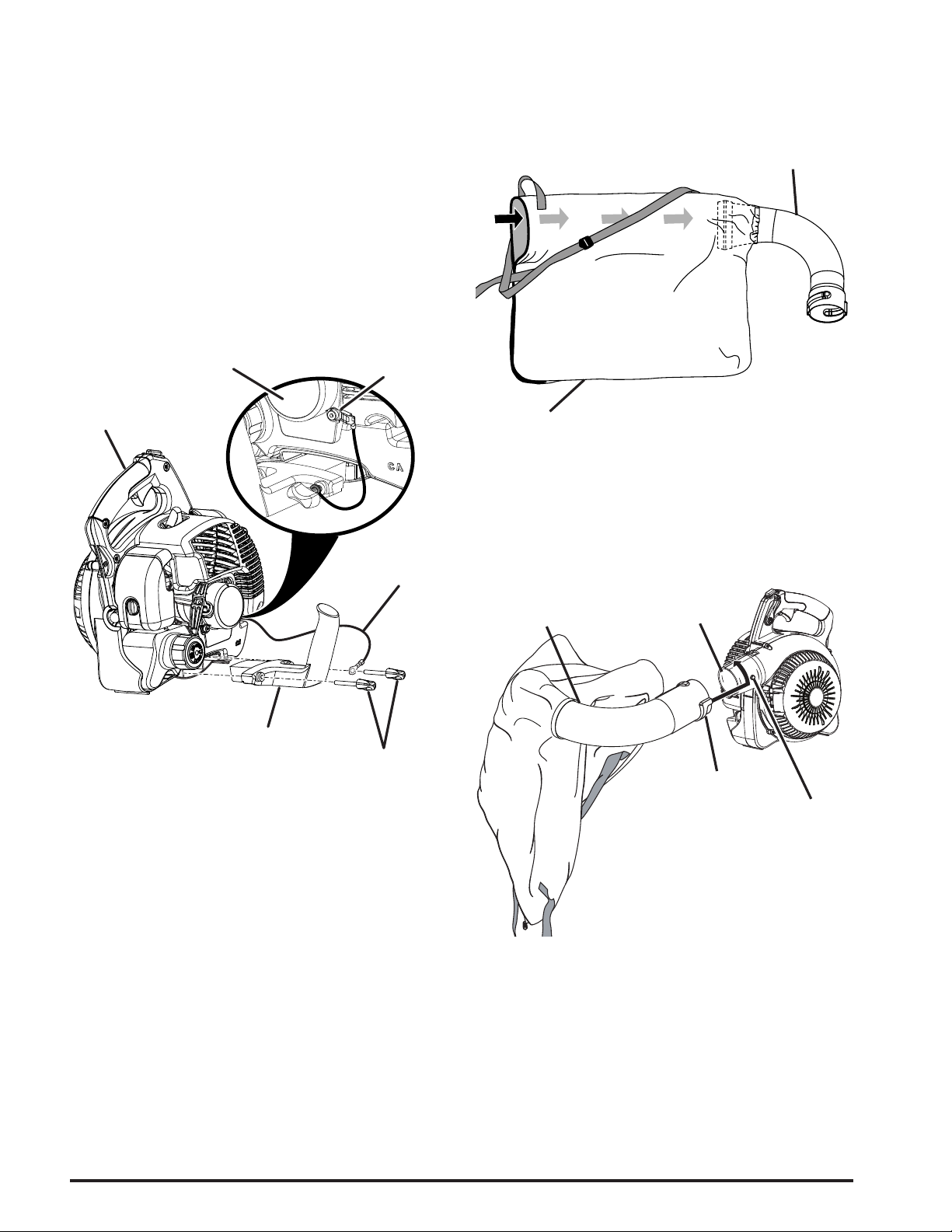
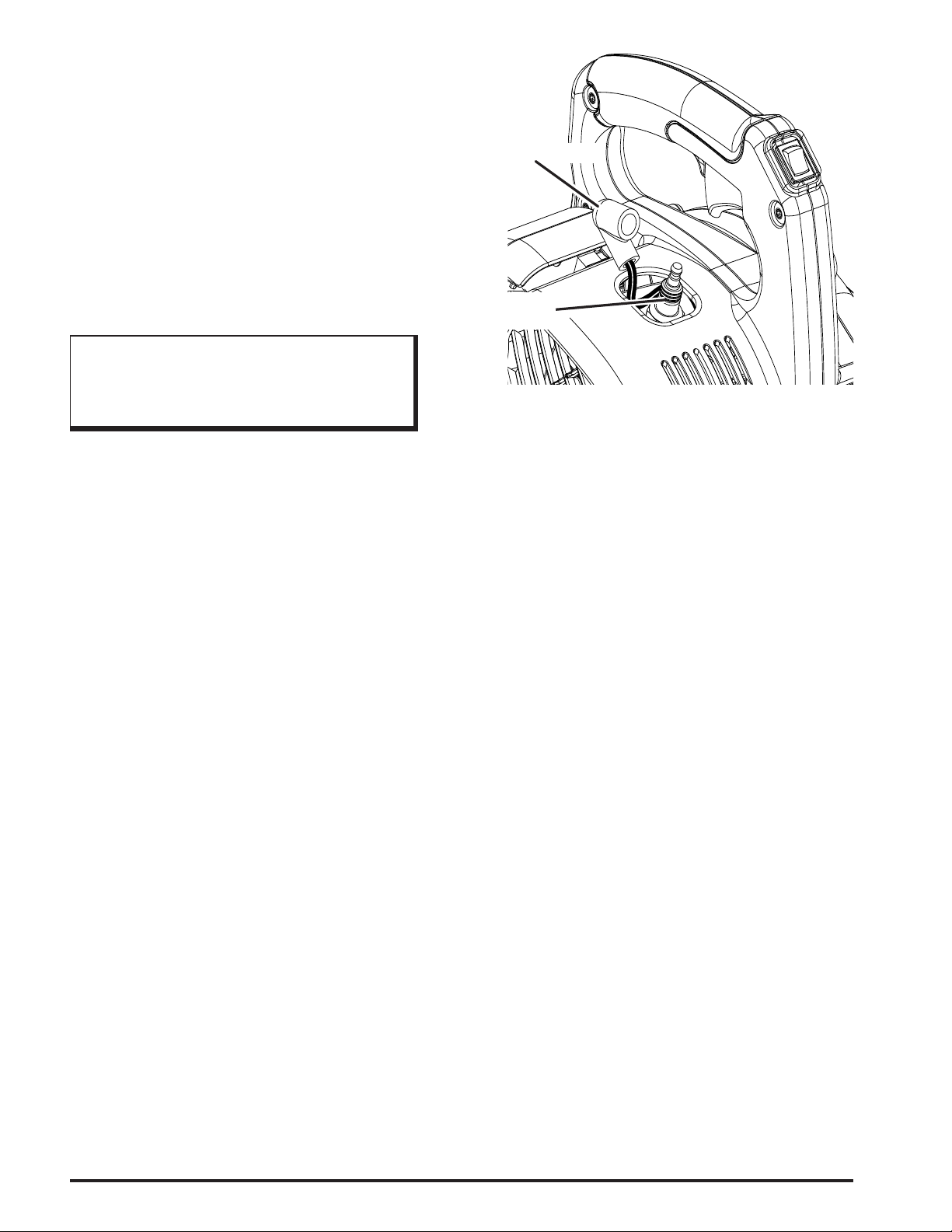
GROUNDING INSTRUCTIONS
See Figure 4.
A grounding wire is provided to help prevent static shock
when using the vacuum in low humidity conditions.
INSTALLING THE VACUUM HANDLE
See Figure 4.
1. Connect one end of the grounding wire to the ground-
ing tab located beneath the recoil housing.
2. Connect the other end of the grounding wire to one of
the vacuum handle knob posts.
3. Insert vacuum handle into the base of main housing.
4. Secure vacuum handle in place using vacuum handle
knobs.
RECOIL
HOUSING
UPPER
HANDLE
GROUNDING
TAB
GROUNDING
WIRE
INSTALLING THE VACUUM BAG
See Figures 5 - 6.
1. Remove the sweeper nozzle and upper blower tube
from the main housing by twisting and removing from
main housing outlet.
ADAPTOR
VACUUM BAG
2. Unzip the vacuum bag and place the adaptor inside
as shown. Push the vacuum bag adaptor through the
opening opposite the zipper. The wider end of the adaptor will remain on the inside of the vacuum bag when
installed properly.
MAIN
ADAPTOR INSTALLED
IN VACUUM BAG
HOUSING
OUTLET
Figure 5
VACUUM
HANDLE
VACUUM
HANDLE
KNOBS
Figure 4
RAISED
SLOT
3. Align the raised slots on the vacuum bag adaptor with
the raised locking tabs on the main housing outlet; push
the bag adaptor onto the housing. Twist to lock into
place.
4. Rotate the vacuum bag until the shoulder strap is up-
right.
5. Make sure the vacuum bag is zipped and closed before
starting the unit.
RAISED
LOCKING
TAB
Figure 6
12
Assembly
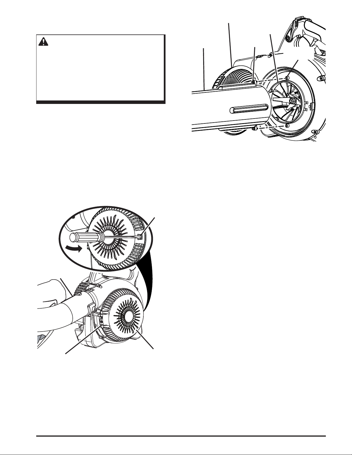
INSTALLING THE VACUUM TUBES
See Figures 7 - 8.
WARNING:
Rotating impeller blades can cause severe
injury. Always stop the engine and ensure
impeller blades have stopped rotating before
opening the vacuum door or installing/changing
tubes. Do not put hands or any other object into
the vacuum tubes while they are installed on the
unit.
To install the vacuum tubes:
1. Secure the upper and lower vacuum tubes together by
aligning the raised locking tabs with the raised slots.
2. Tap tube assembly on ground until the screw holes
in lower tube are in the raised slot of the upper tube.
Secure with supplied screws. See gure 1.
3. Depress door tab using a straight screwdriver and open
vacuum inlet door.
4. Align screw mounts on vacuum opening with screws on
vacuum tube assembly.
5. Turning clockwise, tighten screws on upper vacuum
tube to secure to main housing.
DOOR TAB
INLET DOOR
UPPER
VACUUM TUBE
To remove the vacuum tubes:
1. Loosen screws of the upper vacuum tube by turning
counterclockwise.
2. Remove the vacuum tube assembly from the main
housing.
3. Close the inlet cover door securely.
VACUUM
OPENING
SCREW
SCREW
MOUNT
Figure 8
VACUUM BAG
ASSEMBLY
VACUUM
DOOR
HINGE
VACUUM INLET
DOOR
Figure 7
Assembly
13
Operation
WARNING:
Do not allow familiarity with tools to make you
careless. Remember that a careless fraction of a
second is sufcient to inict serious injury.
WARNING:
Always wear eye protection with side shields
marked to comply with ANSI Z87.1, along with
hearing protection. Failure to do so could result
in objects being thrown into your eyes and other
possible serious injuries.
APPLICATIONS
You may use this tool for the purposes listed below:
Clear leaves and other debris from your lawn
Keep decks and driveways free from leaves and pine
needles
MIXING THE FUEL
This product is powered by a 2-cycle engine and requires
pre-mixing gasoline and 2-cycle oil. The mixture should be
at a 50:1 ratio.
To mix the fuel:
1. Use a clean container that is approved for use with
gasoline.
2. Mix the 2-cycle engine oil with unleaded gasoline in
the container, according to the instructions on the oil
package.
NOTE: This engine is certied to operate on unleaded gaso-
line intended for automotive use with an octane rating of 87
[(R + M) / 2] or higher. Do not use automotive oil or 2-cycle
outboard oil.
NOTE: Fuel mixture will stay fresh up to 30 days. DO NOT
mix quantities larger than can be used in a 30 day period.
FILLING THE TANK
WARNING:
Gasoline is extremely ammable and explosive.
A re or explosion from gasoline will burn you
and others. Always shut off engine before fuel-
ing. Never add fuel to a machine with a running
or hot engine. Move at least 30 ft. from refuel-
ing site before starting engine. Do not smoke
and stay away from open ames and sparks.
Failure to safely handle fuel could result in serious personal injury.
1. Clean the surface around the fuel cap to prevent con-
tamination.
2. Loosen the fuel cap slowly, by turning it counterclock-
wise.
3. Pour the fuel mixture carefully into the tank.
4. Clean and inspect the fuel cap gasket before replacing
the fuel cap.
5. Replace the fuel cap and tighten it by turning it clock-
wise.
6. Wipe spilled fuel from the product.
7. Move at least 30 ft. (9 m) away from refueling area
before starting the product.
NOTE: It is normal for smoke to be emitted from a new
engine during rst use.
WARNING:
Check for fuel leaks. A leaking fuel cap is a re
hazard and must be replaced immediately. If
you nd any leaks, correct the problem before
using the product. Failure to do so could result
in a re that could cause serious personal injury.
HIGH QUALITY 2-CYCLE ENGINE LUBRICANT
GASOLINE 50:1 LUBRICANT
1 gallon (US) 2.6 oz.
1 liter 20 cc (20 ml)
14
OXYGENATED FUELS
DO NOT USE E85 FUEL. IT WILL VOID YOUR
WARRANTY.
Ethanol. Gasoline containing up to 10% ethanol by volume
(commonly referred to as E10) or 15% ethanol by volume
(commonly referred to as E15) are acceptable.
Do not use E85 fuel.
NOTE: Fuel system damage or performance problems re-
sulting from the use of an oxygenated fuel containing more
than the percentages of oxygenates stated previously are not
covered under warranty.
Operation
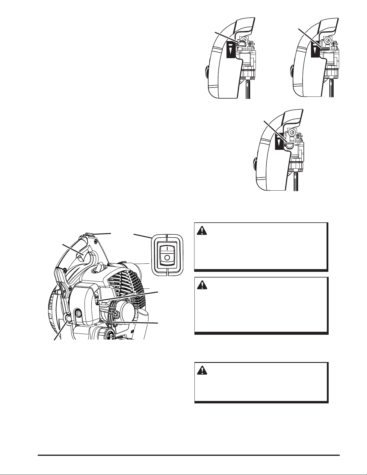
STARTING AND STOPPING
See Figures 9 - 10.
To start a cold engine:
DO NOT squeeze the throttle trigger until the engine starts
and runs.
1. Set the Powervac™ on a at, bare surface.
2. Slowly press the primer bulb 8 times.
NOTE: After the 8th press, fuel should be visible in
the primer bulb. If it is not, continue to press the primer
until you see fuel in the bulb.
3. Place the choke lever in the FULL CHOKE position.
4. Pull throttle lock back to lock the throttle wide open.
5. Pull the starter grip and rope sharply until engine at-
tempts to run. Do not pull the starter grip more than
four (4) times.
6. Set the choke lever in the HALF CHOKE position.
7. Pull the starter grip and rope until the engine runs. Do
not pull the starter grip more than six (6) times.
NOTE: If the engine does not start, return to the FULL
CHOKE position and repeat steps 3 through 6 again.
8. Allow the engine to run for 20 seconds, then place the
choke lever in the RUN position.
NOTE: In cooler environments, additional pulls of the
starter handle may be required with the choke lever in
the FULL CHOKE position.
FULL
CHOKE
CHOKE
HALF
FULL
HALF
RUN
RUN
POSITION
FULL
HALF
RUN
OPERATING THE BLOWER
See Figures 11 - 12.
FULL
HALF
RUN
Figure 10
THROTTLE
TRIGGER
STOP
SWITCH
CHOKE
LEVER
STARTER
GRIP AND
ROPE
PRIMER BULB
Figure 9
To start warm engine:
1. Place the choke lever in the RUN position.
2. Pull throttle lock back to lock the throttle wide open.
3. Pull the starter grip and rope until the engine runs.
NOTE: If the engine does not start, repeat steps 3
through 7 again.
To stop the engine:
1. Press and hold the stop switch in the stop (O) position
until the engine stops.
WARNING:
Never run the unit without the blower tubes
installed or the vacuum door securely closed.
Failure to follow these steps could result in pos-
sible serious injuries.
WARNING:
Always wear eye protection with side shields
marked to comply with ANSI Z87.1, along with
hearing protection. Failure to do so could result
in objects being thrown into your eyes and other
possible serious injuries.
1. Start the blower. Refer to Starting and Stopping earlier
in this manual. Hold the blower with the upper handle
in your right hand.
WARNING:
Keep away from the mufer and all other hot
surfaces of the blower. Failure to do so could
result in possible serious personal injury.
2. To keep from scattering debris, blow around the outer
edges of a debris pile. Never blow directly into the
center of a pile.
Operation
15
3. Operate power equipment at reasonable hours only - not
early in the morning or late at night when people might
be disturbed. Comply with the times listed in local
ordinances.
4. To reduce sound levels, limit the number of pieces of
equipment used at any one time.
5. Conserve water by using power blowers instead of
hoses for many lawn and garden applications, including
areas such as gutters, screens, patios, grills, porches,
and gardens.
6. Operate blower at the lowest possible throttle speed to
do the job.
7. Check your equipment before operation, especially the
mufer, air intakes, and air lters.
8. Use rakes and brooms to loosen debris before blowing.
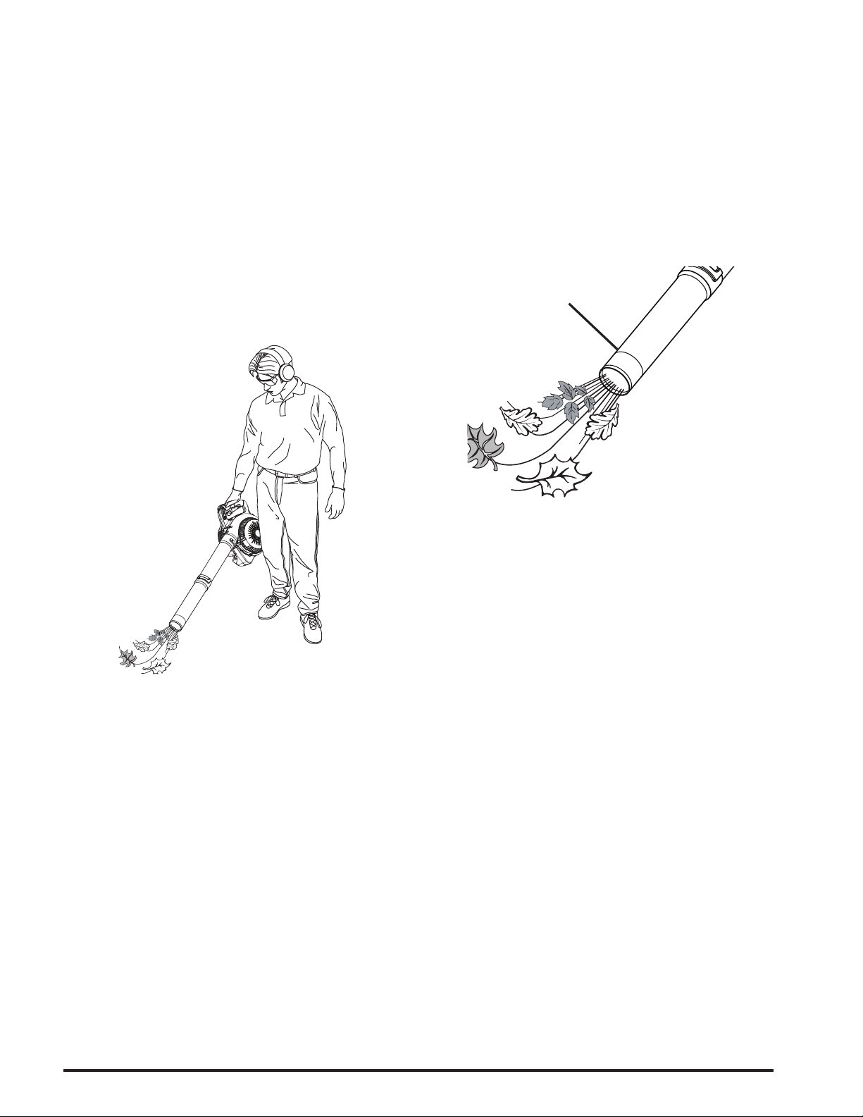
PROPER OPERATING POSITION
9. In dusty conditions, slightly dampen surfaces when
water is available.
10. Watch out for children, pets, open windows, or freshly
washed cars, and blow debris safely away.
11. Use the sweeper nozzle so the air stream can work close
to the ground.
12. After using blowers or other equipment, CLEAN UP!
Dispose of debris properly.
13. Use the sweeper nozzle for the everyday blowing op-
eration. This nozzle allows for more area to be covered
during the blowing operation.
SWEEPER NOZZLE
Figure 11
Figure 12
THROTTLE LOCK
See Figure 13
The throttle lock can be used to operate the blower without
holding the throttle trigger.
To engage the throttle lock:
1. Pull throttle lock back towards user, and stop at the
desired throttle setting.
16
Operation
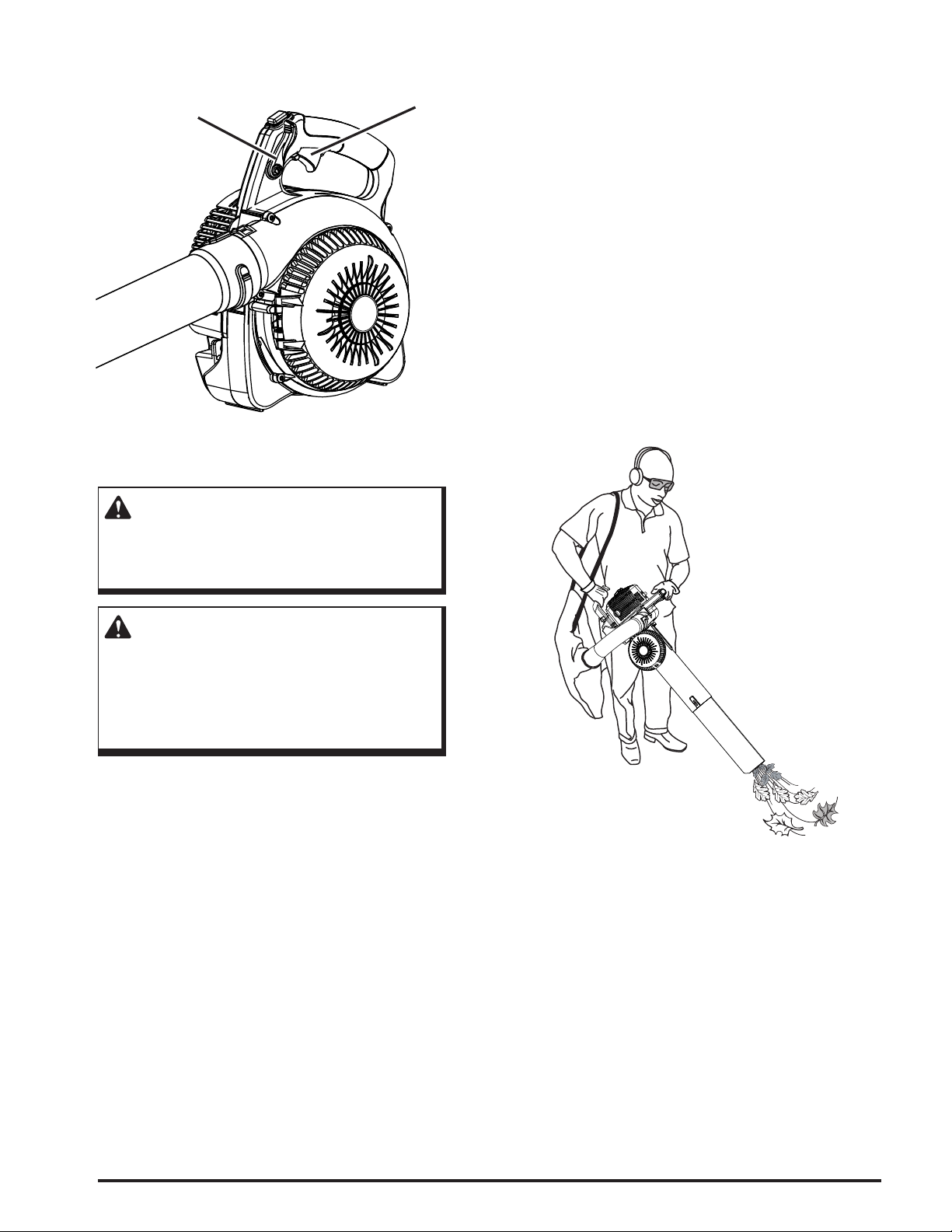
2. To release the throttle lock, push throttle lock all the
way towards the front of unit.
THROTTLE LOCK
THROTTLE TRIGGER
4. Move the vacuum from side to side along outer edge of
the debris. To avoid clogging, do not place the vacuum
tube directly into the debris pile.
5. Hold the engine higher than the inlet end of the vacuum
tube.
6. Always point vacuum tube downhill when working on a
hillside.
7. To avoid injury to the operator or unit, do not pick up
rocks, broken glass, bottles, or other similar objects.
8. If the vacuum tubes should clog, stop the engine and
disconnect the spark plug wire before cleaning out the
obstruction.
9. Remove the vacuum tubes and clear the debris from
the blower fan housing. Remove the bag and clear the
adaptor. A small rod or stick may be required to clear
the entire tube length. Ensure that all debris has been
cleared before reassembling the vacuum tubes.
Figure 13
VACUUM OPERATION
See Figure 14.
WARNING:
Never run the unit without the vacuum tubes
and vacuum bag installed. Failure to do so could
result in serious personal injury.
WARNING:
Always wear eye protection with side shields
marked to comply with ANSI Z87.1, along with
hearing protection. Failure to do so could result
in objects being thrown into your eyes and other
possible serious injuries.
1. Install the vacuum tubes, vacuum handle, and bag.
Refer to the Assembly section earlier in this manual.
2. Start the engine. Refer to Starting and Stopping earlier
in this manual.
3. Place the vacuum bag strap over your right shoulder.
Hold the upper handle in your left hand and the vacuum
handle in your right hand.
PROPER OPERATING POSITION
HOLD MUFFLER AWAY FROM BODY AND CLOTHING
Figure 14
Operation
17
MAINTENANCE
WARNING:
When servicing, use only identical Toro
replacement parts. Use of any other parts may
create a hazard or cause product damage.
WARNING:
Always wear eye protection with side shields
marked to comply with ANSI Z87.1, along with
hearing protection. Failure to do so could result
in objects being thrown into your eyes and other
possible serious injuries.
WARNING:
Before inspecting, cleaning, or servicing the
machine, shut off engine, wait for all moving
parts to stop, and disconnect spark plug wire
and move it away from spark plug. Failure to
follow these instructions can result in serious
personal injury or property damage.
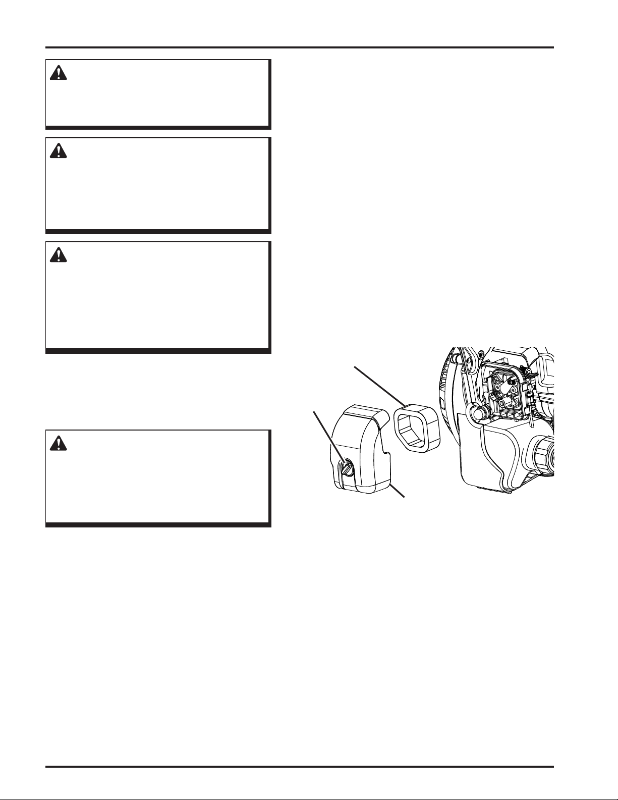
CLEANING AIR FILTER
See Figure 15.
A wet or dirty air lter can affect the way the engine starts,
performs, and wears. The air lter should be checked and
cleaned after 5 hours of operation. Inspect and clean more
frequently if used in dusty dirty conditions.
For best performance, the air lter should be replaced every
25 hours or yearly.
To clean the air lter:
1. Loosen the knob on the air lter cover.
2. Remove the cover.
3. Lift the edge of the air lter carefully and peel it out.
4. Wash the air lter with warm, soapy water.
5. Rinse and squeeze to dry.
6. Reinstall the air lter.
NOTE: Make sure the lter is seated properly inside
the cover. Installing the lter incorrectly will allow dirt
to enter the engine, causing rapid engine wear.
7. Install the air lter cover.
8. Tighten knob to secure.
GENERAL MAINTENANCE
Avoid using solvents when cleaning plastic parts. Most
plastics are susceptible to damage from various types of
commercial solvents and may be damaged by their use.
Use clean cloths to remove dirt, dust, oil, grease, etc.
WARNING:
Do not at any time let brake uids, gasoline,
petroleum-based products, penetrating oils, etc.,
come in contact with plastic parts. Chemicals
can damage, weaken or destroy plastic which
may result in serious personal injury.
AIR FILTER
KNOB
AIR FILTER
COVER
Figure 15
18
Maintenance
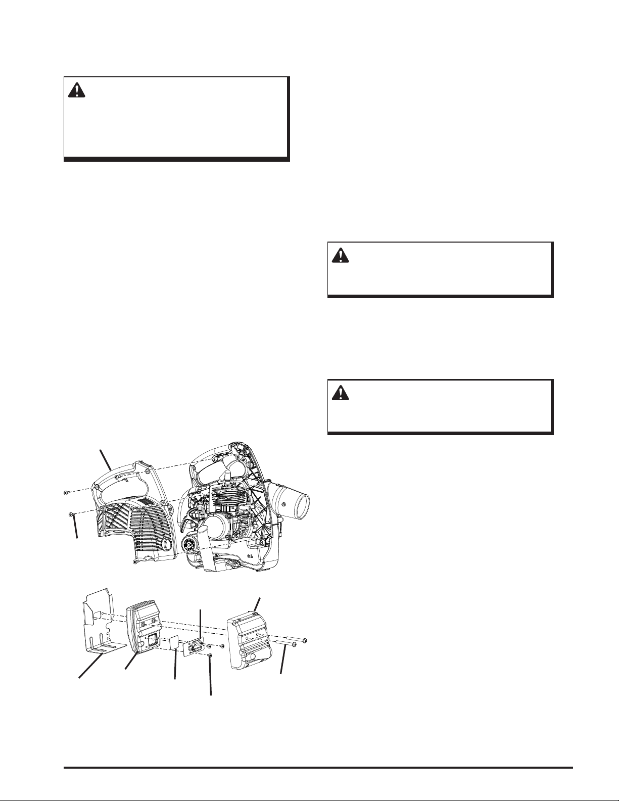
CLEANING THE EXHAUST PORT,
MUFFLER, AND SPARK ARRESTOR
See Figure 16.
WARNING:
Ensure mufer has had time to cool before
performing maintenance on the mufer and/or
spark arrestor and wear gloves. A hot mufer
may cause serious burns.
NOTE: Depending on the type of fuel used, the type and
amount of oil used, and/or your operating conditions, the
exhaust port and mufer may become blocked with carbon
deposits. If you notice a power loss with your gas powered
tool, you may need to remove these deposits to restore
performance. We highly recommended that only qualied
service technicians perform this service.
The spark arrester should be replaced after 25 hours of use.
Replacement parts available online at www.toro.com.
To replace the spark arrester:
Note: Removing these screws requires the use of a T20
and T25 torx screwdriver.
1. Remove the ve screws that hold the cover.
2. Remove the cover.
3. Remove the two screws holding the mufer assembly in
place.
4. Remove the mufer assembly and mufer gasket. It
may be necessary to work the mufer assembly free
from the mufer gasket.
5. Separate the mufer cover from the mufer.
6. Remove the three screws that hold the plates on the
mufer.
7. Remove the spark arrester.
8. Replace the old spark arrester with the new one.
9. Assemble the mufer by reinstalling the plates and
tightening the three screws (torque to 18 in.lb
[2.03 Nm] minimum, 22 in.lb. [2.48 Nm] maximum).
10. Reassemble the mufer and mufer cover and attach to
the mufer gasket with the two screws.
11. Reinsert the mufer assembly and tighten two screws to
engine (torque to 60 in.lb [6.78 Nm] minimum, 80 in.lb.
[9.04 Nm] maximum).
12. Reinstall the cover on the tool and fasten with the ve
screws (torque to 16 in.lb [1.81 Nm] minimum,
22 in.lb. [2.49 Nm] maximum).
NOTE: Do not over-tighten screws.
WARNING:
To avoid a re hazard, never run the Powervac™
without the spark arrestor in place.
VACUUM BAG
A dirty bag will reduce performance. To clean the bag, turn it
inside out and shake. Wash the bag in soapy water at least once
a year. Replacement parts available online at www.toro.com.
FUEL CAP
WARNING:
A leaking fuel cap is a re hazard and must be
replaced immediately.
Cover
Screw(s)
Muffler
Gasket
Muffler
Plate
Spark
Arrester
Screw(s)
The fuel cap contains a non-serviceable lter and a check
valve. A clogged fuel lter will cause poor engine per-
formance. If performance improves when the fuel cap is
loosened, the check valve may be faulty or lter clogged.
Replace the fuel cap if required.
Muffler
Cover
Screw(s)
Figure 16
Maintenance
19
SPARK PLUG REPLACEMENT
See Figure 17.
This engine uses a Champion RCJ6Y spark plug. Use an
exact replacement every 25 hours or annually.
1. Remove the spark plug boot.
2. Loosen the spark plug by turning it counterclockwise
with a socket.
3. Remove the spark plug.
4. Hand thread the new spark plug into the cylinder , turn-
ing it clockwise.
5. Tighten with a socket. (torque to 170 in.lb. [19.21 Nm]
minimum, 190 in.lb. [21.47 Nm] maximum. Do not
over-tighten).
CAUTION:
Be careful not to cross-thread the spark plug.
Cross-threading will seriously damage the
product.
STORING THE PRODUCT
1. Clean all foreign material from the product. Store unit
indoors in a dry, well-ventilated area that is inaccessible
to children. Keep away from corrosive agents such as
garden chemicals, fertilizer, and de-icing salts.
2. Abide by all ISO and local regulations for the safe stor-
age and handling of gasoline.
Spark Plug Boot
Spark
Plug
Figure 17
When storing 1 month or longer:
1. Drain all fuel from tank into a container approved for
gasoline.
2 Drained fuel can be safely disposed of by using it in
your non-diesel car or truck. Run engine until it stops.
3. Place choke lever in the FULL CHOKE position.
4. Pull throttle lock back to lock the throttle.
5. Attempt to start the engine ve (5) more times.
20
Maintenance

EMISSIONS MAINTENANCE SCHEDULE
Maintenance, replacement, or repair of the emission control device and systems may be performed by any nonroad engine repair establishment or individual.
Emission Part
Fuel Tank Assembly (Includes Fuel
Lines, Fuel Cap, and Fuel Filter)
Air Filter
Spark Arrester
Spark Plug
Mufer
X
X X
X
X
X
Inspect
before
each use
Clean every
5 hours
Replace every
25 hours
or yearly
Clean every
25 hours
or yearly
Replace
every
125 hours
HIGH ALTITUDE ENGINE OPERATION:
Have an authorized service center modify this engine if it is to be run above 2000 feet [609.6 m]. Failure to do
so may result in poor engine performance, spark plug fouling, hard starting, and increased emissions. Carburetor modication by an authorized service center will improve performance and allow that engine to meet the EPA
(Environmental Protection Agency) and CARB (California Air Resources Board) emission standards.
An engine modied for high altitudes can not be run below 2000 feet [609.6 m]. The engine will overheat and
result in serious engine damage. Please have an authorized service center restore high altitude modied engines to
the original factory specication before operating below 2000 feet [609.6 m].
TROUBLESHOOTING
IF THESE SOLUTIONS DO NOT SOLVE THE PROBLEM, CONTACT YOUR AUTHORIZED SERVICING DEALER.
PROBLEM CAUSE REMEDY
Engine fails to start. No fuel in tank.
Spark plug shorted or fouled.
Spark plug is broken (cracked porcelain or
electrodes broken).
Ignition lead wire shorted, broken, or
disconnected from spark plug.
Ignition inoperative.
Engine hard to start. Water in gasoline or stale fuel mixture.
Too much oil in fuel mixture.
Engine is under or over-choked.
Weak spark at spark plug.
Engine lacks power. Air lter clogged.
Spark plug fouled.
Spark arrestor/mufer/exhaust port deposits.
Engine overheats. Insufcient oil in fuel mixture. Mix fuel and oil as described in starting
Fill tank with fresh fuel/oil mixture.
Replace spark plug.
Replace spark plug.
Replace lead wire or attach to spark plug.
Contact authorized service center.
Drain entire system and rell with fresh fuel/oil
mixture.
Drain and rell with correct fresh fuel/oil mixture.
Adjust choke as necessary.
Contact authorized service center.
Clean/replace the air lter.
Replace the spark plug.
Clean/replace spark arrestor /mufer parts as
required.
instructions.
Troubleshooting
21

WARRANTY
THIS PRODUCT IS MANUFACTURED UNDER
LICENSE FROM THE TORO COMPANY BY
TECHTRONIC INDUSTRIES NORTH AMERICA, INC.
Techtronic Industries north America, Inc. warrants to the
original retail purchaser that this Blower/Vacuum Product is
free from defects in material and workmanship and agrees to
repair or replace, at our option, any defective Product free of
charge within these time periods from the date of purchase:
Three years for Blower/Vacuum Products, if the Prod-
uct is used for personal, family, or household use;
90 days, if Blower/Vacuum Products are used for any
other purpose, such as commercial or rental.
Three years for emissions control systems on Blower/
Vacuum Products used for any purpose, as provided
below.
Except as provided in the Emission Control Warranty Statement, this warranty extends to the original retail purchaser
only and commences on the date of original retail purchase.
Instructions for Obtaining Warranty
Service
Any part of the Product manufactured or supplied by
Techtronic Industries North America, Inc. and found in
the reasonable judgement of Techtronic Industries North
America, Inc. to be defective in material or workmanship
will be repaired or replaced by an authorized service dealer
for this product without charge for parts and labor. To locate
your nearest authorized service dealer for this product, con-
tact us Toll free at 1-866-574-9242 (US) or 1-866-574-9243
(Canada).
The Product including any defective part must be returned
to an Authorized Service Dealer for this product within the
warranty period. The expense of delivering the Blower/
Vacuum Product to the service dealer for warranty work and
the expense of returning it back to the owner after repair
or replacement will be paid for by the owner. Techtronic
Industries North America. Inc.’s responsibility in respect to
claims is limited to making the required repairs or replace-
ments and no claim of breach of warranty shall be cause
for cancellation or rescission of the contract of sale of any
Product. Proof of purchase will be required by the dealer to
substantiate any warranty claim. All warranty work must
be performed by a service dealer authorized by Techtronic
Industries North America, Inc. to service this product.
This warranty does not cover any Blower/Vacuum Product
that has been subject to misuse, neglect, negligence, or accident, or that has been operated in any way contrary to the
operating instructions as specied in the operator’s manual.
This warranty does not apply to any damage to the Blower/
Vacuum Product that is the result of improper maintenance
or to any Blower/Vacuum Product that has been altered or
modied so as to adversely affect the products operation,
performance or durability or that has been altered or modied so as to change its intended use. The warranty does
not extend to repairs made necessary by normal wear or by
the use of parts or accessories which are either incompat-
ible with the Blower/Vacuum Product or adversely affect its
operation, performance or durability.
In addition, this warranty does not cover the following
(except to the extent covered by the emissions control
warranty set forth below):
A. Tune-ups – Spark Plugs, Carburetor Adjustments, Filters
B. Wear Items – Starter Pulley, Starter Ropes, Mulch-
ing Blades, Blower Fans, Blower and Vacuum Tubes,
Vacuum Bag and Straps
Techtronic Industries North America, Inc. reserves the right
to change or improve the design of any Blower/Vacuum
Product without assuming any obligation to modify any
product previously manufactured.
ALL IMPLIED WARRANTIES ARE LIMITED IN
DURATION TO THE STATED WARRANTY PERIOD.
ACCORDINGLY, ANY SUCH IMPLIED WARRANTIES INCLUDING MERCHANTABILITY, FITNESS
FOR A PARTICULAR PURPOSE, OR OTHERWISE,
ARE DISCLAIMED IN THEIR ENTIRETY AFTER THE
EXPIRATION OF THE APPROPRIATE THREE-YEAR
OR NINETY DAY WARRANTY PERIOD. TECHTRONIC
INDUSTRIES NORTH AMERICA, INC.’S OBLIGATION
UNDER THIS WARRANTY IS STRICTLY AND EXCLUSIVELY LIMITED TO THE REPAIR OR REPLACE-
MENT OF DEFECTIVE PARTS AND TECHTRONIC
INDUSTRIES NORTH AMERICA, INC. DOES NOT
ASSUME OR AUTHORIZE ANYONE TO ASSUME FOR
THEM ANY OTHER OBLIGATION. SOME STATES
DO NOT ALLOW LIMITATIONS ON HOW LONG AN
IMPLIED WARRANTY LASTS, SO THE ABOVE LIMITATION MAY NOT APPLY TO YOU.
TECHTRONIC INDUSTRIES NORTH AMERICA, INC.
ASSUMES NO RESPONSIBILITY FOR INCIDENTAL,
CONSEQUENTIAL, OR OTHER DAMAGES INCLUDING, BUT NOT LIMITED TO EXPENSE OF RETURNING THE BLOWER/VACUUM PRODUCT TO A
BLOWER/VACUUM AUTHORIZED SERVICE DEALER
AND EXPENSE OF DELIVERING IT BACK TO THE
OWNER, MECHANIC’S TRAVEL TIME, TELEPHONE,
OR TELEGRAM CHARGES, RENTAL OF A LIKE
PRODUCT DURING THE TIME WARRANTY SERVICE
IS BEING PERFORMED, TRAVEL, LOSS, OR DAM-
AGE TO PERSONAL PROPERTY, LOSS OF REVENUE,
LOSS OF USE OF THE PRODUCT, LOSS OF TIME, OR
INCONVENIENCE. SOME STATES DO NOT ALLOW
THE EXCLUSION OR LIMITATION OF INCIDENTAL
OR CONSEQUENTIAL DAMAGES, SO THE ABOVE
LIMITATION OR EXCLUSION MAY NOT APPLY TO
YOU.
This warranty gives you specic legal rights, and you may
also have other rights, which vary, from state to state.
22
Warranty

WARRANTY
THE FOLLOWING CALIFORNIA AIR RESOURCES BOARD (CARB) STATEMENT ONLY APPLIES TO MODEL
NUMBERS REQUIRED TO MEET THE CARB REQUIREMENTS.
TECHTRONIC INDUSTRIES NORTH AMERICA, INC., LIMITED WARRANTY STATEMENT FOR FEDERAL AND
CALIFORNIA EMISSION CONTROL SYSTEMS NON-ROAD AND SMALL OFF-ROAD ENGINES
YOUR WARRANTY RIGHTS AND OBLIGATIONS
The U.S. Environmental Protection Agency (EPA), the California Air Resources
Board (CARB), and Techtronic Industries North America, Inc., are pleased to explain the Emissions Control System Warranty on your 2010 model year non-road
or small off-road engine. In California, new equipment that uses small off-road
engines must be designed, built, and equipped to meet the state’s stringent
anti-smog standards. In other states, new 2000 and later model year non-road
engines must be designed, built, and equipped at the time of sale to meet the
U.S. EPA regulations for small non-road engines. The non-road engine must be
free from defects in materials and workmanship which cause it to fail to conform
with U.S. EPA standards for the first three years of engine use from the date of
sale to the ultimate purchaser. Techtronic Industries North America, Inc., must
warrant the emission control system on your non-road or small off-road engine
for the period of time listed above provided there has been no abuse, neglect,
or improper maintenance of your non-road or small off-road engine.
Your emission control system may include parts such as the carburetor or fuel
injection system, the ignition system, catalytic converters, fuel tanks, valves,
filters, clamps, connectors, and other associated components. Also included
may be hoses, belts and connectors, and other emission-related assemblies.
Where a warrantable condition exists, Techtronic Industries North America, Inc.,
will repair your non-road or small off-road engine at no cost to you, including
diagnosis, parts, and labor performed at an authorized service center for Toro®
brand outdoor products.
MANUFACTURER’S WARRANTY COVERAGE:
This product’s emissions control system is warranted for three years. If any
emission-related part on your engine is defective, the part will be repaired or
replaced by Techtronic Industries North America, Inc., free of charge.
OWNER’S WARRANTY RESPONSIBILITIES
(a) As the non-road or small off-road engine owner, you are responsible for
the performance of the required maintenance listed in your operator’s manual.
Techtronic Industries North America, Inc., recommends that you retain all
receipts covering maintenance on your non-road or small off-road engine, but
Techtronic Industries North America, Inc., cannot deny warranty solely for the
lack of receipts or for your failure to ensure the performance of all scheduled
maintenance. Any replacement part or service that is equivalent in performance
and durability may be used in non-warranty maintenance or repairs, and shall
not reduce the warranty obligations of Techtronic Industries North America,
Inc., (b) As the non-road or small off-road engine owner, you should be aware,
however, that Techtronic Industries North America, Inc., may deny you warranty coverage if your non-road or small off-road engine or a part has failed
due to abuse, neglect, improper maintenance, or unapproved modifications.
(c) You are responsible for presenting your non-road or small off-road engine to
an authorized service dealer as soon as a problem exists. The warranty repairs
should be completed in a reasonable amount of time, not to exceed 30 days.
If you have any questions regarding your warranty rights and responsibilities,
you should contact a Techtronic Industries North America, Inc., Customer Representative at 1-866-574-9242 (US) or 1-866-574-9243 (Canada).
DEFECT WARRANTY COVERAGE REQUIREMENTS:
(a) The warranty period begins on the date the engine or equipment is delivered
to an ultimate purchaser.
(b) General Emissions Warranty Coverage. Techtronic Industries North America,
Inc., warrants to the ultimate purchaser and each subsequent purchaser that
your non-road or small off-road engine is designed, built, and equipped at the
time of sale to conform with all applicable regulations adopted by the California
Air Resources Board or the United States Environmental Protection Agency;
and that it is free from defects in materials and workmanship which cause the
engine to fail to conform with applicable regulations for a period of three years
from the date the non-road or small off-road engine is purchased by the initial
purchaser.
(c) The warranty on emissions-related parts will be interpreted as follows: Any
warranted part that is not scheduled for replacement as required in the Emissions
Maintenance Schedule and Warranty Parts List set forth below is warranted for
three years. If any such part (including any part that is scheduled only for regular
inspection) fails during the period of warranty coverage, it will be repaired or
replaced at any Authorized Service Center at no charge. Any such part repaired
or replaced under warranty will be warranted for the remaining warranty period.
A statement to the effect of “repair or replace as necessary” would not reduce
the period of warranty coverage. Any warranted part that is scheduled for replacement as required maintenance in the Emissions Maintenance Schedule and
Warranty Parts List is warranted for the period of time prior to the first scheduled
replacement point for that part. Any such part repaired or replaced under warranty is warranted for the remainder of the period prior to the first scheduled
replacement point, and will be repaired or replaced at any Authorized Service
Center for no charge until that replacement point is reached.
Techtronic Industries North America, Inc., shall remedy warranty defects at any
authorized Authorized Service Center, including any distribution center that
may be franchised to service the subject engines. Any diagnostic work done at
a Authorized Service Center shall be free of charge to the owner if such work
determines that a warranted part is defective. Any manufacturer-approved or
equivalent replacement part may be used for any warranty maintenance or
repairs on emission-related parts, and must be provided free of charge to the
owner if the part is still under warranty. Techtronic Industries North America,
Inc., is liable for damages to other engine components caused by the failure of
a warranted part still under warranty.
Add-on or modified parts that are not exempted by the California Air Resource
Board may not be used. The use of any non-exempted add-on or modified parts
will be grounds for disallowing a warranty claim. Techtronic Industries North
America, Inc., will not be liable to warrant failures of warranted parts caused by
the use of a non-exempted add-on or modified part.
The California Air Resources Board’s Emission Warranty Parts List specifically
defines the emission-related warranted parts. (EPA’s regulations do not include
a parts list, but the EPA considers emission-related warranted parts to include
all the parts listed below.) Techtronic Industries North America, Inc., will provide
any documents that describe its warranty procedures or policies within five days
upon request by the California Air Resources Board.
EMISSIONS PARTS LIST
Emissions parts vary from product to product. Your emissions control system
warranty applies to any of the following components that may be included on
your product:
(1) Fuel Metering System
(i) Carburetor and internal parts (and/or pressure regulator or fuel injection
system).
(ii) Air/fuel ratio feedback and control system.
(iii) Cold start enrichment system.
(iv) Fuel Tank.
(2) Air Induction System
(i) Controlled hot air intake system.
(ii) Intake manifold.
(iii) Air filter.
(3) Ignition System
(i) Spark Plugs.
(ii) Magneto or electronic ignition system.
(iii) Spark advance/retard system.
(4) Exhaust Gas Recirculation (EGR) System
(i) EGR valve body and carburetor spacer, if applicable.
(ii) EGR rate feedback and control system.
(5) Air Injection System
(i) Air pump or pulse valve.
(ii) Valves affecting distribution of flow.
(iii) Distribution manifold.
(6) Catalyst or Thermal Reactor System
(i) Catalytic converter.
(ii) Thermal reactor.
(iii) Exhaust manifold.
(7) Particulate Controls
(i) Traps, filters, precipitators, and any other device used to capture par-
ticulate emissions.
(8) Miscellaneous Items Used in Above Systems
(i) Electronic controls.
(ii) Vacuum, temperature, and time sensitive valves and switches.
(iii) Hoses, belts, connectors, and assemblies.
Techtronic Industries North America, Inc., will furnish with each new engine
written instructions for its maintenance and use by the owner.
Warranty
23

Customer Service Information
If your product requires service or maintenance, contact your nearest authorized service
dealer. To locate your nearest authorized service dealer for this product, contact us toll free
at 1-866-574-9242 (US) or 1-866-574-9243 (Canada).
This product is manufactured under license from The Toro
Company by Techtronic Industries North America, Inc.
Techtronic Industries North America, Inc.
1428 Pearman Dairy Rd.
Anderson, SC 29621
USA
988000-112
9-10-10 (REV:02)

Form No. 3365-751 Rev. A
POWERVAC
™
Numéro de modèle 51984—310000001 et suivants
Pour toute question condernant le
soufflante, nous appeler au :
1-866-574-9242 (États-Unis) ou le
1-866-574-9243 (Canada).
AVERTISSEMENT :
Pour réduire les risques de blessures, l’utilisateur doit lire et veiller à bien comprendre le Manuel d’Utilisation.
Conserver ce manuel.
Anglais (EN), français (FR) et espagnol (ES)

INFORMATIONS IMPORTANTES
Avant d’utiliser ce Powervac™ pour la première fois, lire les conseils
utiles ci-dessous.
Fueling
AVERTISSEMENT :
L’essence et les vapeurs qu’elle dégage sont
extrêmement inammables et explosives. Pour
éviter des blessures graves et des dommages
matériels, manipuler avec précaution. Garder le
produit à l’écart des sources d’inammation et des
ammes vives, l’utiliser uniquement à l’extérieur,
ne pas fumer et essuyer rapidement tout carburant
répandu.
1. Se procurer un bidon ou jerrycan approuvé pour l’essence.
2. Mélanger la totalité du acon d’huile moteur 2 à 4 litres (1 gallon) d’essence sans plomb
à 87 octanes (50:1).
3. Remplir le réservoir du soufante avec précaution.
Démarrage à froid et à chaud
En cas d’incertitude en ce qui concerne la température du moteur avant de le relancer, mettre le volet
de départ en position MARCHE, verrouiller le volet des gaz position ouverte, et tirer le cordon du
lanceur. Si le moteur ne démarre pas après 5 tractions du cordon, consulter la section « Démarrage
d’un moteur froid », plus loin dans ce manuel.
Moteur noyé
Si le moteur ne démarre pas, il peut être noyé. Ne pas s’inquiéter, ce problème peut facilement être
corrigé. Mettre le levier du volet de départ en position MARCHE. Asegurar el acelerador et tirer le
manchon en lanceur à rappel rapidement 10 à 12 fois. Si le moteur ne démarre pas, voir la section «
Dépannage », plus loin dans ce manuel ou appeler gratuitement le
1-866-574-9242 (États-Unis) ou le 1-866-574-9243 (Canada).
Pour toute question concernant le
soufflante nous contacter gratuitement
CALL
1-866-574-9242 (US) or
1-866-574-9243 (Canada)
au 1-866-574-9242 (ÉU) or
1-866-574-9243 (Canada).
AVERTISSEMENT : The engine exhaust from this product contains chemicals
known to the State of California to cause cancer, birth defects or other reproductive harm.
CALIFORNIA PROPOSITION 65
2

TABLE DES MATIÈRES
Introduction ...................................................................................................................................................................................4
Règles de Sécurité .........................................................................................................................................................................5
Règles de Sécurité Particulières ....................................................................................................................................................6
Symboles .......................................................................................................................................................................................7
Autocollants ..................................................................................................................................................................................8
Caractéristiques ....................................................................................................................................................................... 9-10
Fiche Technique .....................................................................................................................................................................9
Outils Nécessaires .......................................................................................................................................................................10
Assemblage ............................................................................................................................................................................11-13
Déballage ............................................................................................................................................................................. 11
Assemblage Des Tubes de Soufante ..................................................................................................................................11
Instructions De Mise À La Terre .........................................................................................................................................11
Installation De La Poignée D’aspirateur ..............................................................................................................................12
Installation Du Sac À Débris ...............................................................................................................................................12
Installation Des Tubes D’aspiration ............................................................................................................................... 12-13
Utilisation .............................................................................................................................................................................. 14-17
Applications .........................................................................................................................................................................14
Mélange Du Carburant ........................................................................................................................................................14
Remplissage Du Réservoir ..................................................................................................................................................14
Carburants Oxygénés ...........................................................................................................................................................14
Démarrage Et Arrêt ..............................................................................................................................................................15
Utilisation De La Soufante .......................................................................................................................................... 15-16
Régulateur De Vitesse .................................................................................................................................................... 16-17
Utilisation De L’aspirateur ...................................................................................................................................................17
Entretien ................................................................................................................................................................................ 18-21
Entretien Général .................................................................................................................................................................18
Nettoyage Du Filtre À Air ...................................................................................................................................................18
Nettoyage De L’orice D’échappement, Du Silencieux Et Pare-Étincelles ........................................................................19
Sac À Débris ........................................................................................................................................................................19
Bouchon Du Réservoir ........................................................................................................................................................19
Remplacement De La Bougie ..............................................................................................................................................20
Remisage Le Produit ............................................................................................................................................................20
Programme D’entretien Du Système Antipollution .............................................................................................................20
Fonctionnement Du Moteur À Haute Altitude ....................................................................................................................21
Dépannage ...................................................................................................................................................................................21
Garantie ................................................................................................................................................................................. 22-24
Table des matières
3

INTRODUCTION
Merci d’avoir acheté un produit Toro.
Nous tenons à ce que vous soyez entièrement satisfait de votre nouveau produit. N’hésitez donc pas à contacter un
concessionnaire réparateur agréé pour tout ce qui concerne l’entretien et le dépannage, la commande de pièces détachées ou
tout renseignement qui pourrait vous être utile.
Lors de tout contact avec un concessionnaire agréé, veiller à disposer des numéros de modèle et de série du produit. Ces
numéros aideront le représentant de service à fournir des informations exactes sur le produit particulier. L’autocollant de
numéros de modèle et de série est apposé sur le boîtier du moteur.
Pour plus de commodité, noter le numéro de série dans l’espace ci-dessous.
No. de modèle
No. de série
Étiquette
de Données
Lire ce manuel attentivement pour apprendre à utiliser et entretenir le produit correctement. La lecture de ce manuel aidera
à protéger l’opérateur et les autres personnes présentes contre les risques de blessures et à éviter des dommages au produit.
Bien que les outils conçus, fabriqués et commercialisé soient des produits de la plus haute qualité, étudiés pour offrir une
sécurité maximum, il incombe à leurs propriétaires de les utiliser correctement et en toute sécurité. Il incombe également au
propriétaire de l’outil d’instruire les personnes autorisées à l’utiliser au sujet de la sécurité d’utilisation.
Tout au long de ce manuel, Toro utilise un système d’identication des dangers potentiels et des messages de sécurité destinés
à permettre à l’opérateur et aux personnes présentes d’éviter des risques de blessures graves, voire mortelles. Les termes
DANGER, AVERTISSEMENT et ATTENTION sont utilisés pour indiquer le niveau de risque. Toutefois, quel que soit le
niveau de risque, la plus extrême prudence est de rigueur. Deux autres termes, « Important » et « Remarque », sont destinés
à attirer l’attention sur des informations importantes.
4
Introduction

RÈGLES DE SÉCURITÉ
AVERTISSEMENT :
Lire attentivement toutes les instructions. Le non-respect de toutes les instructions ci-dessous peut
entraîner un choc électrique, un incendie et / ou une intoxication par le monoxyde de carbone, ce qui peut
causer des blessures graves voire la mort.
Ne pas laisser des enfants ou personnes n’ayant pas reçu
une formation adéquate utiliser cet unité.
Ne jamais lancer ou faire tourner le moteur dans un
endroit clos. Les gaz d’échappement peuvent être
mortels.
Toujours porter une protection oculaire certiée
conforme à la norme ANSI Z87.1 ainsi qu’un protection
auditive. Si cette précaution n’est pas prise, des objets
peuvent être projetés dans les yeux et causer des lésions
graves.
Garder les badauds, enfants et visiteurs à une distance de
15 m (50 pi).
Porter des pantalons longs, manches longues, des
chaussures de travail et des gants épais. Ne pas porter de
vêtements amples, shorts, sandales, bijoux quels qu’ils
soient et ne pas travailler pieds nus.
Pour réduire le risque de blessure lié aux objets aspirés
dans les pièces rotatives, ne porter ni vêtements amples,
ni foulards, ni chaînette de cou, ni d’autres accessoires
semblables. Attacher les cheveux longs au-dessus des
épaules an d’éviter de les coincer dans les pièces
rotatives.
Ne pas utiliser cet unité en état de fatigue, si l’on est
souffrant ou sous l’inuence de l’alcool, de drogues ou
de médicaments.
Ne pas travailler sous un éclairage insufsant.
Garder toutes les parties du corps à l’écart des pièces en
mouvement et des parties brûlantes de l’outil.
Porter un masque facial ltrant dans les milieux
poussiéreux an de réduire le risque de lésions lié à
l’inhalation de poussière.
Examiner la zone de travail avant chaque utilisation. La
débarrasser de tous les objets tels que cailloux, verre
brisé, clous, ls métalliques, cordes, etc. risquant d’être
projetés ou de se prendre dans la machine.
Se tenir bien campé et en équilibre. Ne pas travailler
hors de portée. Le travail hors de portée risque de faire
perdre l’équilibre ou de causer un contact avec les pièces
brûlantes.
Ne jamais utiliser l’outil sans le pare-étincelles, qui se
trouve dans le silencieux.
Les produits utilisés sur les territoires des services
forestiers des États-Unis et de certains états doivent
être conformes aux réglementations de lutte contre
l’incendie. Cet outil est doté d’un pare-étincelles,
toutefois, d’autres dispositifs peuvent être requis.
Consulter les autorités locales et gouvernementales.
Laisser le moteur refroidir avant de remiser l’outil.
Utiliser exclusivement des pièces de rechange et
accessoires Toro. Ne pas suivre cette recommandation
peut entraîner un mauvais fonctionnement et des
blessures.
Entretenir l’outil conformément aux instructions de ce
Manuel d’Utilisation.
Inspecter le produit avant chaque utilisation pour
s’assurer qu’il n’y a pas de pièces desserrées, de fuites
de carburant, etc. Remplacer les pièces endommagées
avant utilisation.
Ne pas utiliser sur une échelle, un toit, dans un arbre
ou sur toute surface instable. Une position stable sur
une surface solide garantit un meilleur contrôle de la
Powervac™ dans des situations imprévues.
DÉPANNAGE
Avant de nettoyer, réparer ou inspecter, arrêter le moteur
et vérier que toutes les pièces en mouvement sont
immobilisées. Déconnecter le l de bougie et le garder
à l’écart de la bougie an d’empêcher un démarrage
accidentel.
Le dépannage de la Powervac™ doit exclusivement
être coné à un personnel qualié. Les réparations ou
entretiens par des personnes non qualiées peuvent
entraîner des blessures ou dommages à l’outil.
Utiliser exclusivement des pièces identiques à celles
d’origine pour la Powervac™. L’usage de pièces non
autorisées peut présenter des risques de blessures ou de
dommage pour l’outil.
Règles de sécurité
5

RÈGLES DE SÉCURITÉ PARTICULIÈRES
Toujours tenir la soufante avec la main droite. Voir
UTILISATION plus loin dans ce manuel, pour des
informations plus détaillées.
Pour réduire les risques de perte de l’ouïe causée par le
niveau sonore, porter une protection auditive.
Pour réduire les risques de blessures inigées par des
pièces en rotation, arrêter le moteur avant d’installer ou
de retirer des accessoires. Toujours débrancher le l de
bougie avant de procéder à un entretien ou d’accéder à
des pièces en mouvement.
Ne jamais utiliser l’outil comme soufante sans d’abord
installer les tuyaux de la soufante.
Ne jamais utiliser la soufante sans les tubes installés.
Ne jamais rien insérer dans les tubes.
Utiliser exclusivement selon les instructions de ce
manuel.
Ne pas utiliser l’aspirateur sans le sac, car des débris
pourraient être projetés et iniger des blessures graves.
Toujours fermer le sac complètement avant d’utiliser
l’aspirateur.
Les pales de ventilateur en rotation peuvent causer des
blessures graves. Arrêter le moteur avant d’ouvrir le
volet d’aspiration ou d’installer/changer les tubes. Ne pas
mettre les mains ou quelque objet que ce soit dans les
tubes installés sur la machine.
Ne jamais utiliser la soufante sans les accessoires
appropriés installés. Les tubes de soufante doivent
toujours être installés lorsque la machine est utilisée en
soufante. Lorsque la machine est utilisée pour aspirer,
les tubes d’aspiration et le sac doivent toujours être
installés. Pour éviter la projection de débris, s’assurer que
la fermeture à glissière de sac est complètement fermée
lorsque le moteur tourne.
Éviter les situations pouvant mettre le feu au sac. Ne pas
utiliser la machine à proximité de ammes vives. Ne pas
aspirer les cendres chaudes de cheminées, barbecues,
feux de bois, etc. Ne pas aspirer de mégots de cigares
ou cigarettes dont les cendres ne sont pas complètement
froides.
RAVITAILLEMENT EN CARBURANT
Le carburant est extrêmement inammable. Lors de
l’utilisation, prendre les précautions nécessaires pour
réduire le risque de blessures graves.
Conserver le carburant dans une zone froide bien
ventilée à l’écart d’étincelles et / ou de matériels
produisant des ammes.
Conserver le carburant dans des jerrycans spécialement
conçus à cet effet.
Toujours faire le plein à l’extérieur et ne pas fumer
pendant cette opération.
Faire l’appoint de carburant avant de lancer le moteur.
Ne jamais retirer le bouchon du réservoir de carburant
ni faire l’appoint pendant que le moteur tourne ou est
chaud.
Ne pas fumer pendant la manipulation du carburant.
Mélanger et conserver le carburant dans un bidon ou
jerrycan approuvé pour l’essence.
Mélanger le carburant à l’extérieur, loin de toute amme
ou source d’étincelles.
Desserrer le bouchon du réservoir lentement pour
relâcher la pression et éviter que le carburant s’échappe.
Une fois le réservoir plein, remettre le bouchon en place
et le serrer fermement.
Essuyer tout le carburant éventuellement répandu.
S’éloigner de 9 m (30 pi) du point d’approvisionnement
avant de lancer le moteur.
N’essayer en aucun cas de brûler le carburant répandu.
Manipuler le carburant avec précaution pour éviter les
risques d’incendies et de brûlures. Le carburant est
extrêmement inammable.
Si du carburant est répandu, ne pas essayer de lancer le
moteur, mais éloigner la machine et éviter de créer une
source d’inammation jusqu’à ce que les vapeurs de
carburant se soient dissipées.
Remettre en place les bouchons de jerrycan et de
réservoir de carburant et les serrer fermement.
Pour le transport dans un véhicule, le réservoir doit être
vide et la machine bien arrimée.
Lors de la vidange du réservoir de carburant, utiliser
un bidon ou jerrycan approuvé pour la conservation de
carburant et procéder dans un endroit bien aéré.
Poser la machine sur un sol nu, arrêter le moteur et le
laisser refroidir avant de faire le plein.
Conserver ces instructions. Les consulter fréquemment
et les utiliser pour instruire les autres utilisateurs
éventuels. Si cet outil est prêté, il doit être accompagné
de ces instructions.
6
Règles de Sécurité Particulières

SYMBOLES
Les termes de mise en garde suivants et leur signication ont pour but d’expliquer le degré de risques associé à l’utilisation de ce produit.
SYMBOLE SIGNAL SIGNIFICATION
DANGER : Indique une situation extrêmement dangereuse qui, si elle n’est
pas évitée, aura pour conséquences des blessures graves ou mortelles.
AVERTISSEMENT : Indique une situation potentiellement dangereuse qui, si elle n’est
pas évitée, pourrait entraîner des blessures graves ou mortelles.
ATTENTION : Indique une situation potentiellement dangereuse qui, si elle n’est
pas évitée, pourraît entraîner des blessures légères ou de gravité
modérée.
ATTENTION : (Sans symbole d’alerte de sécurité) Indique une situation pouvant
entraîner des dommages matériels.
Certains des symboles ci-dessous peuvent être présents sur la produit. Veiller à les étudier et à apprendre leur
signication.
SYMBOLE NOM EXPLICATION
Symbole d’alerte de sécurité Indique un risque de blessure potentiel.
Pour réduire les risques de blessures, l’utilisateur doit lire et veiller
Lire le manuel d’utilisation
Porter une protection oculaire
et auditive
Volet d’aspiration Ne pas actionner lorsque le volet d’aspiration n’est pas verrouillé.
Cheveux longs Risque d’aspiration des cheveux longs dans l’entrée d’air.
Tubes de soufante Ne pas utiliser sans les tubes en place.
Vêtements amples Risque d’aspiration des vêtements amples dans l’entrée d’air.
Essence et lubriant
à bien comprendre le manuel d’utilisation avant d’utiliser ce
produit.
Porter une protection oculaire munie d’écrans latéraux certiée
conforme à la norme ANSI Z87.1, ainsi qu’une protection auditive
et respiration lors de l’utilisation de cet outil.
Use unleaded gasoline intended for motor vehicle use with an
octane rating of 87 [(R + M) / 2] or higher. This product is powered
by a 2-cycle engine and requires pre-mixing gasoline and 2-cycle
lubricant.
Symboles
Symbole « Arrêt »
Pour arrêter le moteur, appuyer sur l’interrupteur et le maintenir en
position d’arrêt.
7

AUTOCOLLANTS
®
®
Les autocollants d’instructions et de mises en garde sont placés bien en vue de l’opérateur, près des pièces présentant un danger potentiel. Remplacer immédiatement tout autocollant manquant ou endommagé.
Part No. 940835003Part No. 940654088
Part No. 940927001 Part No. 940908001
8
Autocollants

CARACTÉRISTIQUES
Fiche technique
Nom Caractéristique
Poids 4,4 kg (9,7 lb)
Moteur 25,4 cc, vilebrequin complet
Vitesse de l’air
Mi/h Jusqu’à 160 (257.5 kph)
Pi3/min Jusqu’à 420 (11.89 m3/min)
FENTE EN SAILLIE
BANDOULIÈRE
RÉGULATEUR
DE VITESSE
CADRE
PRINCIPAL
TUBE
D’ASPIRATION
INFÉRIEUR
VIS DU TUBE
D’ASPIRATION
SAC À DÉBRIS
POIGNÉE DU
LANCEUR ET
CORDE
D’AMORÇAGE
POIGNÉE
SUPÉRIEURE
LEVIER DE
VOLET DE
DÉPART
POIRE
TUBE D’ASPIRATION
SUPÉRIEUR
GÂCHETTE
D’ACCÉLÉRATEUR
POIGNÉE
D’ASPIRATEUR
BOUGIE
LEVIER DE
VOLET DE DÉPART
Caractéristiques
BOUCHON DU
RÉSERVOIR
Figure 1
9

CARACTÉRISTIQUES
COMMUTATEUR
DE MOTEUR
RÉGULATEUR
DE VITESSE
SILENCIEUX
EMBOUT ÉVENTAIL
TUBE SUPÉRIEUR
APPRENDRE À CONNAÎTRE LA
SOUFFLANTE/ASPIRATEUR
Voir les gures 1-2.
La sécurité d’utilisation de ce produit exige la
compréhension des informations apposées sur l’outil
et contenues dans ce manuel d’utilisation, ainsi que la
connaissance du travail à exécuter. Avant d’utiliser ce
produit, se familiariser avec toutes ses fonctions et règles de
sécurité.
TUBE DE SOUFFLANTE ET EMBOUTS
Les tuyaux de la soufante peuvent être assemblés et
installés sur le logement principal sans utiliser d’outils.
RÉGULATEUR DE VITESSE
Le régulateur de vitesse permet d’utiliser la soufante sans
maintenir le doigt sur la gâchette. Pour ralentir le moteur,
il suft de pousser la manette de régulateur de vitesse vers
l’avant.
MOTEUR
Cette soufante est équipée d’un moteur de 25,4 cc,
assez puissant pour s’acquitter des tâches de soufage et
d’aspiration les plus dures.
GÂCHETTE
D’ACCÉLÉRATEUR
POIGNÉE
SUPÉRIEURE
CADRE
PRINCIPAL
VOLET D’ENTRÉE
D’AIR
Figure 2
BROYEUR
La soufflante est dotée d’une lame de broyage en métal
qui réduit efficacement le volume des feuilles de 10:1.
EMBOUT ÉVENTAIL
L’embout éventail permet de couvrir une surface plus large.
GÂCHETTE D’ACCÉLÉRATEUR
La soufante peut être utilisée à n’importe quelle vitesse
entre le ralenti et le régime maximum.
ASPIRATEUR/BROYEUR
Il est possible de convertir facilement la soufante en un
aspirateur ou un broyeur à l’aide d’un tournevis à tête plate.
SAC À DÉBRIS
Le sac à débris se monte sur la cadre principal au moyen
d’un adaptateur.
POIGNÉE D’ASPIRATEUR
Cette fonction permet de s’acquitter des travaux d’aspiration
confortablement.
TUBES D’ASPIRATION
Il est possible d’installer les tuyaux de l’aspirateur sur la
cadre principal à l’aide d’un tournevis à tête plate.
OUTILS NÉCESSAIRES
Le outil suivants (non inclus ou dessiné pour escalader) est nécessaires pour effectuer l’assemblage :
TOURNEVIS À LAME PLATE
10
Caractéristiques

ASSEMBLAGE
DÉBALLAGE
Ce produit doit être assemblé.
Avec précaution, sortir le produit et les accessoires de la
boîte. S’assurer que toutes les pièces gurant sur la liste
de contrôle sont incluses.
AVERTISSEMENT :
Ne pas utiliser le produit si, en le déballant,
vous constatez que des éléments gurant dans
la liste des pièces sont déjà assemblés. Cer-
taines pièces gurant sur cette liste n’ont pas
été assemblées par le fabricant et exigent une
installation. Le fait d’utiliser un produit qui a
été assemblé de façon inadéquate peut entraîner
des blessures
AVERTISSEMENT :
Ne pas essayer de modier ce produit ou de
créer des accessoires non recommandés pour le
produit. De telles altérations ou modications
sont considérées comme un usage abusif et peuvent créer des conditions dangereuses, risquant
d’entraîner des blessures graves.
AVERTISSEMENT :
Pour empêcher un démarrage accidentel pouvant entraîner des blessures graves, toujours dé-
connecter le l de la bougie avant d’assembler
des pièces.
Examiner soigneusement le produit pour s’assurer que
rien n’a été brisé ou endommagé en cours de transport
Ne pas jeter les matériaux d’emballage avant d’avoir
soigneusement examiné le produit et avoir vérié qu’il
fonctionne correctement.
Si des pièces sont manquantes ou endommagées, ap-
peler
le 1-866-574-9242 (US) or 1-866-574-9243 (Canada).
LISTE DES PIÈCES
Soufante
Tube supérieur de soufante
Embout éventail
Poignée d’aspirateur
Boutons de poignée d’aspirateur (2)
Tubes d’aspiration supérieur et inférieur
Vis du tube d’aspiration (2)
Sac à débris
Adaptateur de sac à débris
Lubriant 2 temps
Manuel d’utilisation
NOTE : Lire toutes les étiquettes avant de les retirer et de
les ranger avec le manuel d’utilisation.
Assemblage Des Tubes de Soufflante
Voir le gure 3.
1. Aligner les languettes en saillie du boîtier principal sur
les fentes du tube supérieur, emboîter le tube et le ser-
rer fermement en le tournant. Vérier le serrage après
l’utilisation initiale et resserrer selon le besoin.
2. Fixer la buse de balayeuse et le tuyau supérieur de la
soufante ensemble en alignant l’ergot de verrouillage
saillant du tuyau supérieur de la soufante sur la fente
saillante de la buse de balayeuse.
3. Pour les séparer, tourner le tuyau et la buse pour les
déverrouiller et les retirer de la sortie du logement principale.
SORTIE DU CADRE
PRINCIPAL
LANGUETTE DE
VERROUILLAGE
EN SAILLIE
LANGUETTE DE
TUBE DE
SOUFFLANTE
SUPÉRIEUR
VERROUILLAGE
EN SAILLIE
AVERTISSEMENT :
Si des pièces manquent ou sont endommagées,
ne pas utiliser ce produit avant qu’elles aient été
remplacées. Le non-respect de cet avertissement
pourrait entraîner des blessures graves.
Assemblage
EMBOUT ÉVENTAIL
Figure 3
INSTRUCTIONS DE MISE À LA
TERRE
Voir le gure 4.
Un l de mise à la terre est fourni an de prévenir les
décharges statiques lors de l’utilisation de la balayeuse dans
des conditions de faible humidité.
11

INSTALLATION DE LA POIGNÉE
D’ASPIRATEUR
Voir le gure 4.
1. Raccorder une extrémité du l de mise à la terre à la
patte de mise à la terre située en dessous du logement
du lanceur.
2. Raccorder l’autre extrémité du l de terre sur l’un ou
l’autre des boutons de la poignée d’aspirateur.
3. Insérer la poignée dans la base de la cadre principal.
4. Assujettir la poignée au moyen des boutons de la poi-
gnée d’aspirateur.
SAC À DÉBRIS
ADAPTATEUR
POIGNÉE
SUPÉRIEURE
LOGEMENT
DU LANCEUR
LOGEMENT DU
LANCEUR
FIL DE
TERRE
PATTE DE MISE
À LA TERRE
BOUTONS DE
LA POIGNÉE
D’ASPIRATEUR
POIGNÉE
D’ASPIRATEUR
Figure 4
Figure 5
2. Ouvrir le sac à débris et placer l’adaptateur à l’intérieur,
comme illustré. Pousser l’adaptateur du sac à débris
dans l’ouverture située du côté opposé de la fermeture
à glissière. L’extrémité large de l’adaptateur demeurera
à l’intérieur du sac à débris si l’accessoire est correctement installé.
3. Aligner les fentes de l’adaptateur de sac sur les
languettes en saillie de la sortie du cadre principal,
enfoncer l’adaptateur dans son logement. Tourner pour
l’assujettir en place.
4. Tourner le sac pour orienter la bandoulière vers le haut.
5. S’assurer que la fermeture à glissière du sac à débris est
bien fermée avant de mettre l’outil en marche.
SORTIE DU CADRE
PRINCIPAL
ADAPTATEUR INSTALLÉ DANS
LE SAC À DÉBRIS
INSTALLATION DU SAC À DÉBRIS
Voir les gures 5 - 6.
1. Retirer la embout éventail et le tuyau supérieur de la
cadre principal en tournant ce dernier et en le retirant de
la sortie du cadre principal.
12
FENTE EN
SAILLIE
LANGUETTE DE
VERROUILLAGE
EN SAILLIE
Figure 6
Assemblage

INSTALLATION DES TUBES
D’ASPIRATION
Voir les gures 7 - 8.
AVERTISSEMENT :
Les pales de ventilateur en rotation peuvent
causer des blessures graves. Toujours arrêter le
moteur avant d’ouvrir le volet d’aspiration ou
d’installer / changer les tubes. Ne pas mettre
les mains ou quelque objet que ce soit dans les
tubes installés sur la machine.
Installation des tubes d’aspiration :
1. Assembler le tube d’aspiration supérieur sur le tube
inférieur en alignant les languettes en saillie sur les
fentes.
2. Taper l’ensemble des tubes sur le sol, jusqu’à ce que
les trous de vis du tube inférieur soient visibles dans les
fentes du tube supérieur. Assujettir les tubes avec les vis
fournies. Voir la gure 1.
3. Appuyer sur le loquet de la porte à l’aide d’un tournevis à tête plate et ouvrir la trappe d’admission de
l’aspirateur.
4. Aligner la montures de vis de l’ouverture de la balayeuse avec la vis de l’ensemble tuyau de la balayeuse.
5. En tournant en sens horaire, serrer la vis sur le tuyau
supérieur de la balayeuse pour xer au logement
principal.
VOLET D’ENTRÉE D’AIR
TUBE
D’ASPIRATION
SUPÉRIEUR
Retrait des tubes d’aspiration :
1. Desserrer les vis du tuyau supérieur de l’aspirateur en
les tournant dans le sens antihoraire.
2. Retirer les tubes d’aspiration du corps de la cadre
principal.
3. Refermer soigneusement le volet d’entrée d’air.
OUVERTURE
D’ASPIRATION
VIS
MONTAGE
DU VIS
Figure 8
ENSEMBLE
DE SAC À
DÉBRIS
CHARNIÈRE
DU VOLET
D’ASPIRATION
LANGUETTE
DU VOLET
VOLET
D’ENTRÉE
D’AIR
Figure 7
Assemblage
13

UTILISATION
AVERTISSEMENT :
Ne pas laisser la familiarité avec ce produit faire
oublier la prudence. Ne pas oublier qu’une fraction de seconde d’inattention peut entraîner des
blessures graves.
AVERTISSEMENT :
Toujours porter une protection oculaire certiée
conforme à la norme ANSI Z87.1 ainsi qu’un
protection auditive. Si cette précaution n’est pas
prise, des objets peuvent être projetés dans les
yeux et causer des lésions graves.
APPLICATIONS
Ce produit peut être utilisé pour les applications ci-dessous :
Élimination des feuilles et débris des pelouses
Élimination des feuilles et aiguilles de pin des terrasse
MÉLANGE DU CARBURANT
Cet outil utilise un moteur 2 temps qui nécessite le mélange
d’essence et d’huile 2 temps. Le mélange doit être dans un
rapport 50:1
Mélange du carburant :
1. Se procurer un bidon ou jerrycan approuvé pour
l’essence.
2. Mélanger l’huile pour moteur 2 temps à l’essence se
trouvant dans le jerrycan conformément aux instruc-
tions de l’emballage de l’huile.
NOTE : Le moteur est certié pour fonctionner avec de
l’essence sans plomb pour automobiles, avec un indice
d’octane de 87 [(R + M) / 2] ou plus. Ne pas utiliser d’huile
automobile ou pour moteur hors-bord 2 temps.
NOTE : Le mélange reste frais pendant 30 jours maximum.
NE PAS mélanger plus de carburant qu’il ne sera utilisé
dans une période de 30 jours.
L’HUILE POUR MOTEUR 2 TEMPS À L’ESSENCE (50:1)
ESSENCE 50:1 HUILE
1 gallon (US) 2.6 oz.
1 litre 20 cc (20 ml)
REMPLISSAGE DU RÉSERVOIR
AVERTISSEMENT :
L’essence est extrêmement inammable et explosive. Un incendie ou une explosion d’essence
inigerait des brûlures à l’opérateur et aux
autres personnes présentes. Toujours couper le
moteur avant de remettre du carburant. Ne ja-
mais remplir le réservoir d’une machine lorsque
le moteur tourne ou est chaud. S’éloigner d’au
moins 9 m (30 pi) du point d’approvisionnement
avant de lancer le moteur. Ne pas fumer, et
rester à l’écart des ammes vives et des étincelles. Une mauvaise manipulation de l’essence
peut entraîner des blessures graves.
1. Nettoyer le pourtour du bouchon de remplissage pour
éviter la contamination du carburant.
2. Desserrer le bouchon du réservoir en le tournant lente-
ment vers la gauche.
3. Verser le mélange dans le réservoir avec précaution.
4. Avant de remettre le bouchon en place, nettoyer et
inspecter son joint.
5. Remettre le bouchon en place et le serrer en le tournant
vers la droite.
6. Essuyer tout le carburant éventuellement répandu sur
l’outil.
7. S’éloigner d’au moins 9 m (30 pi) du point
d’approvisionnement avant de lancer le moteur
NOTE : Il est normal qu’un moteur neuf dégage de la fumée lors de la première utilisation.
AVERTISSEMENT :
S’assurer de l’absence de fuites de carburant.
Un bouchon de carburant qui fuit pose un risque
d’incendie et doit être remplacé immédiatement. Toutes les fuites doivent être éliminées
avant d’utiliser le produit. Ne pas prendre cette
précaution peut causer un incendie, entraînant
des blessures graves.
CARBURANTS OXYGÉNÉS
NE PAS UTILISER LE CARBURANT E85. LE NONRESPECT DE CETTE DIRECTIVE ENTRAÎNE
L’ANNULATION DE LA GARANTIE.
Ethanol. L’essence contenant jusqu’à 10 % d’éthanol par
volume (généralement désignée E10) ou 15 % d’éthanol
par volume (généralement désignée E15) est acceptable.
L’essence désignée E85 ne l’est pas.
NOTE : Les dommages au circuit de carburant et les prob-
lèmes de performance résultant de l’utilisation de carburant
oxygéné contenant des pourcentages de composants oxygénés supérieurs à ceux indiqués précédemment ne sont pas
couverts par la garantie.
14
Utilisation

DÉMARRAGE ET ARRÊT
Voir les gures 9 - 10.
Démarrage du moteur froid :
NE PAS appuyer sur la gâchette avant que le moteur dé-
marre et reste en marche.
1. Poser le Powervac™ sur un sol nu et plat.
2. Appuyer lentement 8 fois sur la poire d’amorçage
NOTE : Après la 8e pression, on devrait apercevoir du car-
burant dans la poire d’amorçage. Sinon, continuer à presser sur l’amorceur jusqu’à voir du carburant dans la poire.
3. Mettre le volet de départ en position d’étranglement
FULL CHOKE (complètement ouvert).
4. Tirer le levier de verrouillage d’accélération vers l’arrière
pour verrouiller l’accélérateur en position ouverte.
5. Tirer sur le cordon du lanceur jusqu’à ce que le moteur
essaie de démarrer. Ne pas tirer le cordon plus de quatre
(4) fois.
6. Mettre le volet de départ en position HALF CHOKE
(demi étranglement).
7. Tirer sur le poignée du lanceur et corde jusqu’à ce que le
moteur démarre. Ne pas tirer le cordon plus de six (6) fois.
NOTE : Si le moteur ne démarre pas, mettre le levier
d’étrangleur en position « FULL CHOKE » (Complètement ouvert) et répéter les étapes 3 à 6.
8. Laisser le moteur tourner pendant 20 secondes et mettre
le levier du volet de départ en position RUN (marche).
NOTE : Par temps froid, il peut être nécessaire de tirer
le lanceur plusieurs fois lorsque le levier de départ est
en position FULL (ouvert).
GÂCHETTE
D’ACCÉLÉRATEUR
POIRE
D’AMORÇAGE
Démarrage d’un moteur chaud :
1. Mettre le levier du volet de départ en position RUN
(marche).
2. Tirer le levier de verrouillage d’accélération vers l’arrière
pour verrouiller l’accélérateur en position ouverte.
3. Tirer sur le poignée du lanceur et corde jusqu’à ce que
le moteur démarre.
NOTE : Si le moteur ne démarre pas, répéter les étapes
3 à 7.
COMMUTATEUR
D’ARRÊT
LEVIER DE
VOLET DE
DÉPART
POIGNÉE DU
LANCEUR ET
CORDE
Figure 9
COMPLÈTEMENT OUVERT
« FULL CHOKE »
FULL
HALF
RUN
DEMI ÉTRANGLEMENT
« HALF CHOKE »
FULL
HALF
RUN
MARCHE « RUN »
FULL
HALF
RUN
Figure 10
Arrêtez le moteur :
1. Maintenir le commutateur d’arrêt en position « O »
jusqu’à ce que le moteur s’arrête.
UTILISATION DE LA SOUFFLANTE
Voir les gures 11 - 12.
AVERTISSEMENT :
Ne jamais utiliser la soufante sans les tubes
installés ou le volet d’aspiration bien fermé. Le
non-respect de toutes les instructions pouvant
entraîner des blessures.
AVERTISSEMENT :
Toujours porter une protection oculaire certiée
conforme à la norme ANSI Z87.1 ainsi qu’un
protection auditive. Si cette précaution n’est pas
prise, des objets peuvent être projetés dans les
yeux et causer des lésions graves.
1. Mettre la soufante en marche. Voir Démarrage et
arrêt, plus haut dans ce manuel. Tenir la soufante par
la poignée supérieure, avec la main droite.
AVERTISSEMENT :
Ne pas toucher au silencieux et à toute autre surface chaude de la soufante. L’inobservation de
cette règle peut entraîner des blessures graves.
Utilisation
15

2. Pour éviter d’éparpiller les débris, soufer autour des
bords d’un tas de débris. Ne jamais soufer directement
vers le centre d’un tas.
3. N’utiliser les outils motorisés qu’a des heures raison-
nables – pas très tôt le matin ou très tard le soir, an
de ne pas déranger les voisins. Se conformer aux
heures indiquées dans les réglementations locales.
4. Pour réduire le niveau sonore, limiter le nombre d’outils
motorisés utilisés en même temps.
5. Conserver l’eau en utilisant une soufante au lieu de
tuyaux d’arrosage pour divers travaux de jardin et
pelouses, tels que le nettoyage des gouttières, mousti-
quaires, patios, grills, porches et massifs de eurs.
6. Utiliser la soufante à la vitesse la plus basse permet-
tant d’effectuer le travail.
7. Vérier le matériel avant de l’utiliser, en particulier
l’échappement, l’entrée d’air et les ltres à air.
8. Utiliser des râteaux et pelles pour séparer les débris
avant de les soufer.
POSITION D’UTILISATION CORRECTE
9. Dans un environnement poussiéreux humidier légère-
ment les surfaces si de l’eau est disponible.
10. Prêter attention aux enfants, animaux, fenêtres ouvertes
ou véhicules fraîchement lavés et soufer les débris en
direction opposée.
11. Étendre l’embout éventail au maximum de manière à
soufer l’air près du sol.
12. Après utilisation de la soufante ou de tout autre
équipement, NETTOYER ! Pour jeter les débris correctement.
13. Utiliser l’embout éventail pour le nettoyage quotidien.
Cet embout permet de couvrir une surface plus large.
EMBOUT ÉVENTAIL
Figure 11
Figure 12
RÉGULATEUR DE VITESSE
Voir le gure 13
Le régulateur de vitesse permet d’utiliser la soufante sans
maintenir le doigt sur la gâchette.
Pour engager le régulateur de vitesse :
1. Tirer le levier de régulateur de vitesse vers soi, jusqu’à
ce que le régime désiré soit atteint.
16
Utilisation

2. Pour désengager le régulateur de vitesse, pousser son
levier à fond vers l’avant.
GÂCHETTE
RÉGULATEUR DE
VITESSE
D’ACCÉLÉRATEUR
Figure 13
UTILISATION DE L’ASPIRATEUR
Voir le gure 14.
4. Utiliser un mouvement de balayage sur le côté
des débris. Pour éviter l’obturation, ne pas poser
l’embouchure du tube directement sur les débris.
5. Tenir le moteur plus haut que l’extrémité du tube
d’aspiration.
6. Lors du travail sur une pente, toujours diriger le tube
d’aspiration vers le bas de la pente.
7. Pour éviter des blessures ou des dommages à la
machine, ne pas aspirer de cailloux, de verre brisé, de
bouteilles ou autres objets similaires.
8. En cas d’obstruction du tube d’aspiration, arrêter le mo-
teur et débrancher le l de la bougie avant de débloquer
le tube.
9. Retirer les tubes d’aspiration et éliminer les débris du
boîtier de ventilateur. Retirer le sac à débris et déboucher le tube. Il peut être nécessaire d’utiliser une petite
tige ou un bâton pour dégager complètement le tube.
S’assurer que tous les débris ont été enlevés avant de
réassembler les tubes d’aspiration.
POSITION D’UTILISATION CORRECTE
GARDER LE SILENCIEUX À L’ÉCART DU CORPS ET DES
VÊTEMENTS
AVERTISSEMENT :
Ne jamais faire fonctionner l’unité si les tubes
et le sac ne sont pas installés. Le non- respect
de cet avertissement pourrait entraîner des
blessures graves.
AVERTISSEMENT :
Toujours porter une protection oculaire certiée
conforme à la norme ANSI Z87.1 ainsi qu’un
protection auditive. Si cette précaution n’est pas
prise, des objets peuvent être projetés dans les
yeux et causer des lésions graves.
1. Installer les tubes d’aspiration, la poignée d’aspirateur
et le sac à débris. Voir Assemblage, plus haut dans ce
manuel.
2. Mettre la soufante en marche. Voir Démarrage et arrêt,
plus haut dans ce manuel.
3. Placer la bandoulière du sac sur l’épaule droite. Tenir la
poignée supérieure avec la main gauche et la poignée
d’aspirateur, avec la main droite.
Figure 14
Utilisation
17

ENTRETIEN
AVERTISSEMENT :
Utiliser exclusivement des pièces identiques à
celles d’origine pour les réparations. L’usage
de toute autre pièce pourrait créer une situation
dangereuse ou endommager l’outil.
AVERTISSEMENT :
Toujours porter une protection oculaire certiée
conforme à la norme ANSI Z87.1 ainsi qu’un
protection auditive. Si cette précaution n’est pas
prise, des objets peuvent être projetés dans les
yeux et causer des lésions graves.
AVERTISSEMENT :
Avant d’inspecter, nettoyer ou entretenir
l’équipement, arrêter le moteur, attendre l’arrêt
complet de toutes les pièces en mouvement,
déconnecter le l de la bougie et l’écarter
de cette dernière. Le non-respect de ces
instructions peut entraîner des blessures graves
ou des dégâts matériels.
ENTRETIEN GÉNÉRAL
Éviter d’utiliser des solvants pour le nettoyage des pièces
en plastique. La plupart des matières plastiques peuvent
être endommagées par divers types de solvants du com-
merce. Utiliser un chiffon propre pour éliminer la saleté, la
poussière, l’lubriant, la graisse, etc.
Les réglages et réparations décrits ci-dessous peuvent bien
souvent être effectués par l’utilisateur. Les autres réparations
doivent être conées à un centre de réparations agréé.
NETTOYAGE DU FILTRE À AIR
Voir le gure 15.
Un ltre à air encrassé peut nuire au démarrage ainsi que
causer la baisse du rendement et l’usure du moteur. Vérier
et nettoyer le ltre à air après 5 heures de fonctionnement.
Examiner et nettoyer l’outil plus fréquemment s’il est utilisé
dans des conditions poussiéreuses et de grande saleté.
Pour un rendement optimal, remplacer le ltre à air toutes
les 25 heures ou chaque année.
Pour nettoyer le ltre à air :
1. Desserrer le bouton sur le couvercle du ltre à air.
2. Retirer le couvercle.
3. Soulever avec précaution le rebord du ltre à air et le
retirer.
4. Nettoyer le ltre dans de l’eau savonneuse tiède.
5. Le rincer et le laisser sécher.
6. Réinstaller le ltre à air.
NOTE : S’assurer que le ltre est bien appuyé à
l’intérieur du couvercle. Si le ltre est mal installé,
la saleté risque d’entrer dans le moteur, ce qui peut
l’endommager rapidement.
7. Installer le couvercle du ltre à air.
8. Serrer le bouton pour le xer solidement.
FILTRE À
AIR
AVERTISSEMENT :
Ne jamais laisser de liquides tels que le uide de
freins, l’essence, les produits à base de pétrole,
les lubriants pénétrantes, etc., entrer en contact
avec les pièces en plastique. Les produits
chimiques peuvent endommager, affaiblir ou
détruire le plastique, ce qui peut entraîner des
blessures graves.
18
BOUTON
COUVERCLE
DU FILTRE À
AIR
Figure 15
Entretien

NETTOYAGE DE L’ORIFICE
D’ÉCHAPPEMENT, DU SILENCIEUX
ET PARE-ÉTINCELLES
Voir le gure 16.
AVERTISSEMENT :
S’assurer que le silencieux a refroidi avant
d’effectuer tout entretien de cet le silencieux
et / ou pare-étincelles et porter des gants. Un
silencieux brûlante peut causer des brûlures.
NOTE : Suivant le type de carburant utilisé, le type et la
quantité d’huile et/ou les conditions de travail, l’urice
d’échappement et le silencieux peuvent se calaminer. Si
un outil motorisé semble avoir perdu de la puissance, cette
calamine doit être éliminée pour restaurer le fonctionnement
normal. Il est vivement recommandé de coner ce travail à
un technicien qualié.
Il peut être nécessaire de remplacer le pare-étincelles après
25 heures d’utilisation. Les pièces de remplacement sont
disponibles en ligne sur le site suivant : www.toro.com.
Pour remplacer le pare-étincelles :
Note : Pour retirer ces vis, utiliser un tournevis torx
T20 et T25.
1. Déposer les cinq vis qui maintiennent le couvercle.
2. Retirer le couvercle.
3. Retirer les deux vis de xation du silencieux.
4. Retirer le silencieux et son joint. Il peut être nécessaire
de faire faire des mouvements de va et vient au silencieux pour le dégager de son joint.
5. Retirer couvercle du silencieux.
6. Déposer les trois vis qui maintiennent les plaques sur le
silencieux.
7. Retirer le pare-étincelles.
8. Remplacer l’ancien pare-étincelles par le nouveau.
9. Remonter le silencieux en réinstallant les plaques et en
serrant les trois vis. (à un couple de 18 à 22 po-lb [2.03
à 2.48 Nm] maximum. Ne pas trop serrer.).
10. Réassembler le silencieux et le couvercle du silencieux
et les xer au joint de silencieux avec les deux vis.
11. Réinsérer l’ensemble silencieux et le xer au moteur à
l’aide de deux vis. (à un couple de 60 à 80 po-lb [6.78 à
9.04 Nm] maximum. Ne pas trop serrer.)
12. Réinstaller le couvercle sur l’outil et le xer avec les
cinq vis (à un couple de 16 à 22 po-lb [1.81 à 2.49 Nm]
maximum. Ne pas trop serrer.).
Note : Ne pas trop serrer les vis.
AVERTISSEMENT :
Pour éviter les risques d’incendie, ne jamais
utiliser la Powervac™ sans le pare-étincelles.
SAC À DÉBRIS
Un sac encrassé nuit aux performances. Pour nettoyer le sac,
le retourner et le secouer. Le laver dans de l’eau savonneuse
au moins une fois par an. Les pièces de remplacement sont
disponibles en ligne sur le site suivant : www.toro.com.
BOUCHON DU RÉSERVOIR
AVERTISSEMENT :
Un bouchon de carburant qui fuit pose un risque
d’incendie et doit être remplacé immédiatement.
Couvercle
Vis
Joint de
silencieux
Silencieux
Plaque
Pare
étincelles
Le bouchon du réservoir de carburant contient un ltre et
un clapet antiretour non réparables. Un ltre à carburant
colmaté nuit au bon fonctionnement du moteur. Si le fonc-
tionnement du moteur s’améliore lorsque le bouchon est
desserré, le clapet antiretour peut être défectueux ou le ltre
colmaté. Si nécessaire, remplacer le bouchon de carburant.
Couvercle de
silencieux
Vis
Vis
Figure 16
Entretien
19

REMPLACEMENT DE LA BOUGIE
Voir le gure 17.
Ce moteur utilise une bougie RCJ6Y Champion. La bougie
doit être remplacée toutes les 25 heures ou chaque année par
une bougie identique.
Pour remplacer la bougie, procéder comme suit.
1. Retirer le capuchon de la bougie.
2. Desserrer la bougie en la tournant vers la gauche, à
l’aide d’une clé à douille.
3. Retirer la bougie.
4. Visser la nouvelle bougie à la main dans le cylindre à la
main en la tournant vers la droite.
5. Serrer avec une clé à bougie. (à un couple de 170 à 190
po-lb [19.21 à 21.47 Nm] maximum. Ne pas trop serrer.)
ATTENTION :
Veiller à ne pas fausser le letage de la bougie.
Ceci endommagerait sérieusement l’outil.
REMISAGE LE PRODUIT
1. Nettoyer soigneusement le produit. La remiser dans un
endroit bien aéré, inaccessible aux enfants. La tenir à
l’écart de produits corrosifs, tels que les produits chimiques de jardinage, engrais et le sel de dégivrage.
2. Se conformer à toutes les réglementations locales et
gouvernementales concernant la sécurité de la manipulation et de l’entreposage de l’essence.
Capuchon de
la bougie
Bougie
Figure 17
Remisage 1 mois ou plus :
1. Vider complètement le réservoir de carburant dans un
bidon ou jerrycan approuvé pour l’essence.
2. L’essence purgée peut être éliminée en toute sécurité si
elle est utilisée dans une voiture ou un camion à essence
ordinaire. Laisser le moteur tourner jusqu’à ce qu’il
cale.
3. Placer le levier d’étrangleur à la position FULL
CHOKE (complètement ouvert).
4. Tirer le levier de verrouillage d’accélération vers
l’arrière pour verrouiller l’accélérateur.
5. Tenter de faire démarrer le moteur à cinq (5) autres
reprises.
20
Entretien

PROGRAMME D’ENTRETIEN DU SYSTÈME ANTIPOLLUTION
L’entretien, le remplacement ou la réparation des composants et systèmes de contrôle des émissions peuvent être
effectués par toute entreprise ou spécialiste des moteurs non routiers.
Pièce du système
antipollution
Réservoir de carburant
(exibles, bouchon et
ltre inclus)
Filtre à air
Pare-étincelles
Bougie
Silencieux
Inspecter
avant chaque
utilisation.
X
Nettoyer toutes
le 5 heures de
fonctionnement
X
Remplacer toutes
les 25 heures ou
chaque année
X
X
Nettoyer toutes
les 25 heures ou
chaque année
X
Remplacer
toutes les
125 heures
X
FONCTIONNEMENT DU MOTEUR À HAUTE ALTITUDE:
Coner le moteur à un centre de réparations agréé si celui-ci doit être utilisé à une altitude supérieure à 609,6 m
(2 000 pi). Ne pas suivre cette directive peut nuire au bon fonctionnement du moteur, causer l’encrassement de
la bougie d’allumage, nuire au démarrage et augmenter les émissions. En conant l’ajustement des carburateurs
à un centre de réparations agréé, vous améliorerez le rendement du moteur en plus de vous assurer qu’il respecte
les normes de la U.S. Environmental Protection Agency (EPA) et du California Air Resources Board (CARB) en
matière d’émissions. Un moteur qui a été réglé pour fonctionner à haute altitude ne peut être utilisé à 609,9 m
(2 000 pi) ou moins. Ne pas respecter cette directive peut entraîner une surchauffe du moteur et l’endommager
sérieusement. Veuillez coner tout moteur ayant subi des modications en vue d'être utilisé à haute altitude à un
centre de réparations agréé, qui se chargera de le recongurer selon les spécications d’usine d’origine avant qu’il
soit utilisé à une altitude inférieure à 609,6 m (2 000 pi)
DÉPANNAGE
SI LES PRÉSENTES SOLUTIONS NE RÉSOLVENT PAS LE PROBLÈME, CONTACTER LE CENTRE DE
RÉPARATIONS AGRÉÉ.
PROBLÈME CAUSE SOLUTION
Le moteur ne démarre
pas.
Moteur difcile à
lancer.
Le moteur manque de
puissance.
Le moteur surchauffe. Pas assez d’huile dans le mélange. Mélanger l’essence et l’huile tel que décrit dans
Pas de carburant dans le réservoir.
Bougie encrassée ou noyée.
Bougie cassée (porcelaine fendue ou
électrode brisé).
Fil d’allumage court-circuité, brisé ou
déconnecté de la bougie.
Allumage inopérant.
Eau dans le carburant ou mélange défraîchi.
Trop d’huile dans le mélange.
Volet de départ trop ou pas assez ouvert.
Bougie humide.
Filtre à air colmaté.
Bougie encrassée.
Dépôts dans le pare-étincelles, le silencieux
ou l’orice d’échappement.
Remplir le réservoir avec un mélange frais
d’essence et d’huile.
Remplacer la bougie.
Remplacer la bougie.
Remplacer le l d’allumage ou le brancher sur la
bougie.
Contacter un centre de réparations agréé.
Vidanger et remplir avec un mélange frais
d’essence et d’huile.
Vidanger et remplir un mélange frais d’essence et
d’huile
Régler le volet de départ selon le besoin.
Contacter un centre de réparations agréé.
Nettoyer ou remplacer le ltre à air.
Remplacer la bougie d’allumage.
Nettoyer ou remplacer les pièces du pare-étincelles
et du silencieux, au besoin.
les instructions sur le démarrage.
Dépannage
21

GARANTIE
CE PRODUIT EST FABRIQUÉ PAR TECHTRONIC
INDUSTRIES NORTH AMERICA, INC., SOUS LICENCE
DE THE TORO COMPANY.
Techtronic Industries North America, Inc. garantit à l’acheteur
original que ce soufante/aspirateur est exempt de tous vices de
matériaux ou de fabrication et s’engage à réparer ou remplacer
gratuitement, à son choix, tout produit s’avérant défectueux au
cours des périodes indiquées ci-dessous, à compter de la date
d’achat:
Trois ans pour les soufante/aspirateur utilisés par des
particuliers ou leurs familles ;
90 jours sur les soufante/aspirateur utilisés à toutes autres
ns, telles que les travaux commerciaux et la location.
Deux ans sur les systèmes de contrôle des émissions des
soufante/aspirateur à moteur à essence, utilisés pour
quelque application que ce soit, comme indiqué cidessous.
Sauf indication contraire dans l’énoncé de garantie du système
de contrôle des émissions, cette garantie ne couvre que
l’acheteur au détail original et entre en vigueur à la date de
l’achat original.
Comment obtenir le service sous garantie
Toute pièce du produit fabriquée ou fournie par Techtronic
Industries North America, Inc., et jugée, après évaluation
raisonnable par Techtronic Industries North America, Inc.,
comme présentant des vices de matériaux ou de fabrication,
sera réparée ou remplacée par un centre de réparations agréé,
sans facturation pour pièces ou main d’oeuvre. Pour obtenir
l’adresse du centre de réparations agréé le plus proche, appeler
gratuitement le 1-866-574-9242 (États-Unis) ou le
1-866-574-9243 (Canada).
Le produit et toutes les pièces défectueuses devront être
retournés à un centre de réparations agréé avant expiration
de la période de garantie. Les frais d’expédition au centre de
réparations et de retour au propriétaire après réparation ou
remplacement du produit seront assumés par le propriétaire. En
ce qui concerne les réclamations en garantie, la responsabilité
d’Techtronic Industries North America, Inc., se limitera à la
réparation ou au remplacement des produits défectueux et
aucune revendication de rupture de garantie se pourra causer
l’annulation ou la résiliation du contrat de vente d’un produit
quel qu’il soit. Une preuve d’achat sera exigée par le centre
de réparation, an de valider toute réclamation au titre de la
garantie. Toutes les réparations sous garantie devront être
effectuées par un centre de réparations Techtronic Industries
North America, Inc., agréé.
Cette garantie ne couvre pas les soufante/aspirateur ayant
fait l’objet d’un usage abusif ou négligent, d’un manque
d’entretien, ayant été impliqués dans un accident ou employé
de façon contraire aux instructions du manuel d’utilisation.
Cette garantie ne couvre ni les dommages aux soufante/
aspirateur résultant d’un entretien incorrect, ni les produits
altérés ou modiés de façon à nuire au fonctionnement, aux
performances et à la durabilité ou dans le but de l’utiliser
pour un usage autre que celui prévu. La garantie exclut
les réparations rendues nécessaires par l’usure normale ou
l’utilisation de pièces et accessoires incompatibles avec le
soufante/aspirateur à moteur à essence ou nuisibles à son bon
fonctionnement, ses performances ou sa durabilité.
En outre, cette garantie ne couvre pas les articles ci-dessous
(exception faite des pièces couvertes par la garantie sur le
contrôle des émissions, énoncée plus bas)
A. Les réglages – Bougies, réglages du carburateur, ltres.
B. Les articles consommables – Boutons d’avance par choc,
bobines externes, lignes de coupe, bobines internes, poulies
et cordons de lanceur, courroies d’entraînement, dents,
rondelles en feutre, axes d’attelage, lames de paillage,
ventilateur de soufante, tubes de soufage et d’aspiration,
sacs à débris, guide, chaînes de scie
Techtronic Industries North America, Inc., se réserve le
droit d’apporter des modications ou améliorations à tout
produit, sans obligation de modier les produits fabriqués
antérieurement.
LA DURÉE DE TOUTES LES GARANTIES IMPLICITES
NE SAURAIT EN AUCUN CAS EXCÉDER LA PÉRIODE
DE GARANTIE DÉCLARÉE. PAR CONSÉQUENT,
TOUTES LES GARANTIES IMPLICITES, Y COMPRIS
LES GARANTIES DE VALEUR MARCHANDE OU
D’ADÉQUATION À UN USAGE PARTICULIER OU
AUTRES SERONT INVALIDÉES À L’EXPIRATION DE
LA PÉRIODE DE GARANTIE EXPRESSE DE DEUX ANS
OU QUATRE-VINGT-DIX JOURS. LES OBLIGATIONS
D’TECHTRONIC INDUSTRIES NORTH AMERICA,
INC., DANS LE CADRE DE CETTE GARANTIE SE
LIMITENT EXCLUSIVEMENT À LA RÉPARATION OU
AU REMPLACEMENT DES PIÈCES DÉFECTUEUSES
ET TECHTRONIC INDUSTRIES NORTH AMERICA, INC.
N’ASSUME OU N’AUTORISE QUICONQUE À ASSUMER
QUELQUE AUTRE OBLIGATION QUE CE SOIT.
CERTAINS ÉTATS ET PROVINCES NE PERMETTANT
PAS DE LIMITATION DE DURÉE DES GARANTIES
IMPLICITES, LES RESTRICTIONS CI-DESSOUS
PEUVENT NE PAS ÊTRE APPLICABLES.
TECHTRONIC INDUSTRIES NORTH AMERICA, INC.,
DÉCLINE TOUTE RESPONSABILITÉ EN CE QUI
CONCERNE LES DOMMAGES DIRECTS, INDIRECTS OU
AUTRES, Y COMPRIS, MAIS SANS S’Y LIMITER, LES
FRAIS DE RETOUR DU SOUFFLANTE/ASPIRATEUR
À UN CENTRE DE RÉPARATION AGRÉÉ ET DE
RENVOI AU PROPRIÉTAIRE, DE DÉPLACEMENT D’UN
TECHNICIEN, DE TÉLÉPHONE OU TÉLÉGRAMME,
DE LOCATION D’UN PRODUIT SIMILAIRE PENDANT
LA DURÉE DES RÉPARATIONS SOUS GARANTIE,
DE DÉPLACEMENT, DE PERTES OU DOMMAGES À
DES BIENS PERSONNELS, DE MANQUE À GAGNER,
DE PERTE D’USAGE DU PRODUIT, DE PERTE DE
TEMPS OU DE DÉRANGEMENT. CERTAINS ÉTATS
ET PROVINCES NE PERMETTANT L’EXCLUSION
OU LA LIMITATION DES DOMMAGES DIRECTS OU
INDIRECTS, LES RESTRICTIONS CI-DESSOUS PEUVENT
NE PAS ÊTRE APPLICABLES.
Cette garantie donne au consommateur des droits spéciques,
et celui-ci peut bénécier d’autres droits, qui varient selon les
états ou provinces.
22
Garantie

GARANTIE
L’ÉNONCÉ DE CALIFORNIA AIR RESOURCES BOARD (CARB) QUI SUIT, S’APPLIQUE SEULEMENT AUX
NUMÉROS DE MODÈLES QUI DOIVENT SE CONFORMER AUX EXIGENCES DE CARB.
TECHTRONIC INDUSTRIES NORTH AMERICA, INC DÉCLARATION DE GARANTIE LIMITÉE SYSTÈMES DE CONTRÔLE
DES ÉMISSIONS POUR LES ÉTATS-UNIS ET LA CALIFORNIE. PETITS MOTEURS NON ROUTIERS ET HORS ROUTE
VOS DROITS ET RESPONSABILITÉS EN VERTU DE CETTE GARANTIE
L’U.S. Environmental Protection Agency (EPA), le California Air Resources
Board (CARB) et Techtronic Industries North America, Inc. se font un plaisir de
vous expliquer la garantie de conformité du système antipollution de votre petit
moteur non routier ou hors-route, modèle 2010. En Californie, l’équipement neuf
qui utilise les moteurs non routiers ou hors-route, doit être conçu, construit et
équipé conformément aux strictes réglementations sur l’antipollution de cet
État. Dans d’autres États, les moteurs non routiers modèles 2000 et ultérieurs
doivent être conçus, construits et équipés au moment de la vente de façon à être
conformes aux réglementations sur l’antipollution issues par l’EPA (agence de
protection de l’environnement américaine) pour les petits moteurs non routiers.
Le moteur non routier doit être exempt du vices de matériaux et de fabrication
entraînant la non conformité aux réglementations de l’EPA, pendant les trois
premières années d’utilisation, à compter de la date de vente à l’acheteur
d’origine. Techtronic Industries North America, Inc.doit garantir le système de
contrôle des émissions de vos petits moteurs non routiers ou hors-route pour
la période indiquée ci-dessus, à condition que ceux-ci n’aient pas fait l’objet
d’un usage abusif ou d’un manque d’entretien.
Votre système de contrôle des émissions peut inclure des pièces telles que le
carburateur ou le système d’injection de carburant, le système d’allumage, les
convertisseurs catalytiques, les réservoirs de carburant, les valves, les filtres, les
fixations, les connecteurs et d’autres composants connexes. Il peut également
inclure les tuyaux, les courroies, les connecteurs et d’autres articles relatifs au
système d’émissions.
Dans l’éventualité d’un problème couvert par la garantie, Techtronic Industries
North America, Inc. s’engage à réparer gratuitement votre moteur non routier
ou hors-route, ce qui comprend le diagnostique, les pièces et la main-d’oeuvre,
dans un centre de réparations agréé pour les produits de marque Toro®.
DURÉE DE LA GARANTIE DU FABRICANT
Le système de contrôle d’émissions pour ce produit est garanti pour trois ans.
Si une pièce relative au système de contrôle d’émissions de votre moteur est
défectueuse, elle sera réparée ou remplacée sans frais par Techtronic Industries
North America, Inc.
RESPONSABILITÉ DU PROPRIÉTAIRE DANS LE CADRE DE LA
GARANTIE
(a) En tant que propriétaire de ce petit moteur non routier ou hors-route, vous
êtes tenu d’effectuer les entretiens indiqués dans le manuel d’utilisation.
Techtronic Industries North America, Inc. recommande de conserver tous
les reçus relatifs à l’entretien du petit moteur non routier ou hors-route, mais
Techtronic Industries North America, Inc. ne peut par refuser la couverture de
la garantie pour l’unique raison du manque de reçus ou parce que vous avez
omis d’effectuer tous les entretiens prévus. Des pièces et services assurant
des performances et une durabilité équivalente peuvent être utilisées pour
les entretiens et réparations non couverts par la garantie, sans que cela ne
change les obligations de garantie de Techtronic Industries North America,
Inc. (b) Toutefois, en tant que propriétaire du petit moteur non routier ou horsroute, vous devez être averti que les réparations couvertes par la garantie
peuvent être refusées par Techtronic Industries North America, Inc. si la
défaillance de ce moteur ou d’une de ses pièces est due à un usage abusif,
la négligence, un manque d’entretien ou des modifications non approuvées.
(c) Vous êtes tenu de confier votre petit moteur non routier ou hors-route à un centre de réparations agréé dès qu’un problème se présente. Les réparations sous
garantie seront effectuées dans un délai raisonnable, ne dépassant pas 30 jours.
Si vous avez des questions concernant vos droits et responsabilités dans le
cadre de la garantie, contactez un représentant de Techtronic Industries North
America, Inc. au 1-866-574-9242 (EE.UU) ou le 1-866-574-9243 (Canada).
COUVERTURE
(a) La période de la couverture commence à la date de livraison du moteur ou
d’équipement à l’acheteur.
(b) Couverture générale de garantie antipollution. Techtronic Industries North
America, Inc. garantit à l’acheteur d’origine, ainsi qu’à tous les propriétaires
ultérieurs, que son petit moteur non routier ou hors-route est conçu, construit et
équipé conformément à toutes les réglementations de California Air Resources
Board ou United States Environmental Protection Agency en vigueur au moment
de la vente et que son petit moteur non routier ou hors-route sera exempt de
tous défauts de matériaux ou de fabrication causant une non conformité aux
réglementations en vigueur, pour une période de trois ans après l’acquisition
du moteur par l’acheteur d’origine.
(c) La garantie sur les pièces se rapportant au système de contrôle d’émissions
sera interprétée comme suit: Toute pièce couverte par la garantie qui ne doit
pas être remplacée selon le Calendrier d’entretien du système de contrôle
d’émissions et la Liste de pièces garanties, lesquels sont conformément stipulés
ci-dessous, est garantie pour la période de tres ans. Si une telle pièce (y compris les pièces qui doivent seulement être inspectées régulièrement) s’avère
défectueuse, elle sera réparée ou remplacée gratuitement dans un centre de
réparations agréé Techtronic Industries North America, Inc. Toute pièce réparée
ou remplacée dans le cadre ce cette garantie sera garantie pour le reste de la
durée de la garantie. Un énoncé stipulant « réparez ou remplacez au besoin »
ne réduirait pas la période de couverture de la garantie. Toute pièce qui doit
être remplacée conformément au Calendrier d’entretien du système de contrôle
d’émissions et la Liste de pièces garanties est garantie pour la période de temps
précédant le premier remplacement prévu pour cette pièce. Toute pièce de ce
genre réparée ou remplacée dans le cadre de cette garantie est garantie pour
le restant de la période qui précède la première échéance de remplacement,
et elle sera réparée ou remplacée gratuitement dans un centre de réparations
agréé Techtronic Industries North America, Inc. jusqu’au moment ou elle doit
être remplacée.
Techtronic Industries North America, Inc.effectuera les réparations sous garantie dans un centre de réparations Techtronic Industries North America, Inc.
agréé ou chez un concessionnaire. Tout diagnostique effectué dans un centre
de réparations Techtronic Industries North America, Inc.agréé sera gratuit si
le diagnostique aide a déterminer qu’une pièce couverte par la garantie est
défectueuse. Des pièces approuvées par le fabricant ou équivalentes peuvent
être utilisées pour tout entretien ou réparation sous garantie des pièces relatives
au système de contrôle des émissions et doivent être fournies gratuitement au
propriétaire si la pièce est toujours sous garantie. Techtronic Industries North
America, Inc. est responsable des dommages au moteur causés par une pièce
toujours couverte par la garantie.
Des ajouts ou des pièces modifiées qui ne sont pas exemptées par California
Air Resource Board ne peuvent pas être utilisées. L’utilisation de toute pièce
non-exemptée ou modifiée peut justifier le refus d’une réclamation au titre de
la garantie. Techtronic Industries North America, Inc.. ne sera pas responsable
pour des dommages aux pièces sous garantie causés par l’utilisation d’une
pièce non-exemptée ou modifiée.
Le California Air Resources Board a publié une liste de toutes les pièces de
systèmes d’émissions couvertes par une garantie. (Bien que les réglementations de l’EPA n’incluent pas de liste, les pièces qu’elle considère comme
devant être garanties sont indiquées ci-dessous.) Techtronic Industries North
America, Inc.fournira tous les documents relatifs aux procédures et politiques se
rapportant à sa garantie dans les cinq jours suivant une demande de California
Air Resources Board.
LISTE DE PIÈCES DU SYSTÈME DE CONTRÔLE D’ÉMISSIONS
Les pièces du système de contrôle d’émissions varient dépendamment du
produit. Votre garantie du système de contrôle d’émissions s’applique à tous
les composants suivants qui peuvent faire partie de votre produit:
(1) Système de contrôle d’alimentation en carburant
(i) Carburateur et les composants internes (et/ou régulateur de pression
ou système d’alimentation par injection).
(ii) Système de contrôle de rapport air/carburant.
(iii) Système d’enrichissement pour démarrage à froid.
(iv) Réservoir de carburant.
(2) Système d’admission d’air
(i) Système d’admission contrôlée d’air chaud.
(ii) Tubulure d’admission.
(iii) Filtre à air.
(3) Système d’allumage
(i) Bougies d’allumage.
(ii) Système d’allumage magnéto-électrique.
(iii) Système d’avance/retard à l’allumage.
(4) Système de recirculation des gaz d’échappement (RGE)
(i) Corps de vanne et l’espaceur du carburateur de RGE, si applicable.
(ii) Système de contrôle du taux de RGE.
(5) Système d’injection d’air
(i) Pompe à air ou valve à impulsion.
(ii) Valves qui affectent la distribution d’écoulement.
(iii) Distributeur.
(6) Catalyseur ou système de réacteur thermique
(i) Convertisseur catalytique.
(ii) Réacteur thermique.
(iii) Tubulure d’échappement.
(7) Contrôles de particules
(i) Pièges, filtres, électrofiltres et tout autre dispositif utilisé pour capturer
les émissions de particules.
(8) Pièces diverses utilisées dans les systèmes énumérés ci-dessus
(i) Commandes électroniques.
(ii) Valves et interrupteurs sensibles au vide, à la température et au temps.
(iii) Tuyaux, courroies, connecteurs et modules.
Techtronic Industries North America, Inc. fournira au propriétaire des instructions
d’entretien et d’utilisation écrites avec chaque nouveau moteur.
Garantie
23

Service après-vente
Pour tout entretien ou réparation du produit, contacter le centre de réparations agréé le
plus proche. Pour obtenir l’adresse du centre de réparations agréé le plus proche, appeler
gratuitement le 1-866-574-9242 (États-Unis) ou le 1-866-574-9243 (Canada).
Ce produit est fabriqué par Techtronic Industries North
America, Inc., sous licence de The Toro Company.
Techtronic Industries North America, Inc.
1428 Pearman Dairy Rd.
Anderson, SC 29621
États-Unis
988000-112
9-10-10 (REV:02)
Warranty

Form No. 3365-751 Rev. A
POWERVAC
™
Modelo 51984—310000001 en Adelante
Si tiene preguntas en
relación con la soplador,
le suplicamos llamar al
1-866-574-9242 (en EE.UU.) or
1-866-574-9243 (en Canadá).
ADVERTENCIA:
Para reducir el riesgo de lesiones, el usuario debe leer y comprender el Manual del Operador. Guarde este manual.
Inglés (EN), francés (FR) y español (ES)

LEA ESTA INFORMACIÓN
Antes de utilizar su nueva Powervac™, lea las siguientes útiles
sugerencias iniciales.
Abastecimiento de combustible
ADVERTENCIA:
La gasolina y sus vapores son extremadamente
inamables y explosivos. Para evitar graves
lesiones personales y daños materiales, manipule
con cuidado. Mantenga alejado de fuentes de
ignición y llamas expuestas, manipule solamente
en lugares abiertos, no fume y limpie todo derrame
inmediatamente.
1. Obtenga un recipiente limpio aprobado para gasolina.
2. Mezcle todo el aceite para motor de dos tiempos con un galón americano de
gasolina sin plomo con un octanaje de 87 (50:1).
3. Llene cuidadosamente el tanque de gasolina.
Arranque enfrío y en caliente
Cuando vuelve a arrancar la sopladora y no está seguro si aún está caliente el motor, ponga la
palanca del anegador en la posición “MARCHA” (anegador abierto), asegurar el acelerador
apertura total, y tire del cordón del arrancador. Si el motor no arranca a los cinco tirones, consulte el
apartado “Para arrancar con el motor frío”, más abajo en este manual.
Con el motor ahogado
Si no arranca el motor, es posible que esté ahogado. No se preocupe, ya que esto es fácil de corregir.
Ponga la palanca del anegador en la posición “MARCHA” (anegador abierto). Verrouasegurar
el acelerador apertura total y tire con rapidez de la cuerda del arrancador de 10 a 12 veces. Si no
arranca el motor, consulte el apartado “Corrección de problemas”, más abajo en este manual
Para toda pregunta relacionada con su
sopladora, llámenos sin cargo al
1-866-574-9242 (EE.UU.) o la
1-866-574-9243 (Canada)
1-866-574-9242 (EE.UU.) o la 1-866-574-9242
(Canada).
ADVERTENCIA: Las emanaciones provenientes del escape del motor de esta
herramienta contienen productos químicos los cuales, para el gobierno del Estado de California, son
sabidos causantes de cáncer, defectos congénitos u otras afecciones del sistema reproductivo.
California - Propuesta de ley núm. 65
2

ÍNDICE DE CONTENIDO
Introducción ..................................................................................................................................................................................4
Reglas de Seguridad ......................................................................................................................................................................5
Reglas de Seguridad Especícas ...................................................................................................................................................6
Símbolos .......................................................................................................................................................................................7
Etiquetas del Producto ..................................................................................................................................................................8
Características ......................................................................................................................................................................... 9-10
Especicaciones .....................................................................................................................................................................9
Herramientas Necesarias .............................................................................................................................................................10
Armado ..................................................................................................................................................................................11-13
Desempaquetado .................................................................................................................................................................. 11
Montaje de Los Tubos de la Sopladora ................................................................................................................................11
Instrucciones de Conexión a Tierra .....................................................................................................................................11
Instalación del Mango de la Aspiradora ..............................................................................................................................12
Instalación del Saco de la Aspiradora ..................................................................................................................................12
Instalación de los Tubos de la Aspiradora ..................................................................................................................... 12-13
Funcionamiento ..................................................................................................................................................................... 14-17
Aplicaciones ........................................................................................................................................................................14
Mezclado del Combustible ..................................................................................................................................................14
Llenado del Tanque ..............................................................................................................................................................14
Combustibles Oxigenados ...................................................................................................................................................14
Arranque y Apagado ............................................................................................................................................................15
Manejo de la Sopladora ................................................................................................................................................. 15-16
Seguro del Acelerador .................................................................................................................................................... 16-17
Manejo de la Aspiradora ......................................................................................................................................................17
Mantenimiento ...................................................................................................................................................................... 18-21
Mantenimiento General .......................................................................................................................................................18
Limpieza la Filtro de Aire ....................................................................................................................................................18
Limpieza del Oricio de Escape, del Silenciador y Parachispasr .......................................................................................19
Saco de la Aspiradora ..........................................................................................................................................................19
Tapa del Tanque de Combustible .........................................................................................................................................19
Cambio de la Bujía ..............................................................................................................................................................20
Almacenamiento de la Producto ..........................................................................................................................................20
Programa de Mantenimiento Para Control de Emisiones ....................................................................................................21
Operación del Motor a Altitudes Elevadas ..........................................................................................................................21
Corrección de Problemas ............................................................................................................................................................21
Garantía ................................................................................................................................................................................. 22-24
Índice de Contenido
3

INTRODUCCIÓN
Le agradecemos la compra de un producto Toro.
Nos gustaría lograr su completa satisfacción con su nuevo producto, por lo cual le suplicamos ponerse en contacto con un
establecimiento de servicio autorizado si necesita servicio, piezas Toro genuinas o cualquier información.
Siempre que se comunique con un establecimiento de servicio autorizado, tenga a la mano el número de modelo y el de serie
del producto. Estos números ayudan al empleado de servicio a proporcionarle información precisa sobre su producto en
particular. La calcomanía pegada en el alojamiento del motor muestra el número de modelo y el de serie de la herramienta.
Para su conveniencia, escriba el número de modelo y el de serie del producto en el espacio de abajo.
Modelo
Núm. de serie
Data
Label
Lea este manual cuidadosamente de manera que aprenda la forma correcta de manejar y dar mantenimiento a la herramienta.
La lectura de este manual le ayudará a usted y a otras personas a evitar lesiones corporales y daños al producto. Aunque
Toro diseña, fabrica y comercializa productos seguros y técnicamente avanzados, usted es responsable de usar el producto
de manera correcta y segura. También usted es responsable de enseñar a manejar con seguridad la herramienta a quienes les
permite utilizarla.
El sistema de avisos de advertencia empleado por Toro en este manual identica posibles peligros y tiene mensajes especiales
de seguridad que le ayudarán a usted y a otras personas a evitar lesiones corporales, e incluso la muerte. PELIGRO,
ADVERTENCIA y PRECAUCION son palabras de aviso empleadas para identicar el nivel de peligro. No obstante,
independientemente del peligro señalado, siempre tenga extremo cuidado. Dos palabras adicionales, “Importante” y “Nota”,
ponen en relieve determinada información.
4
Introducción

REGLAS DE SEGURIDAD
ADVERTENCIA:
Lea y comprenda todas las instrucciones. El incumplimiento de todas las instrucciones siguientes puede
resultar en descargas eléctricas, incendio o envenenamiento por monóxido de carbono, lo cual puede causar
la muerte o lesiones graves.
No permita que utilicen esta unidad niños ni personas
carentes de la debida instrucción para su manejo.
Nunca arranque ni accione el motor dentro de un área
cerrada; la inhalación de las emanaciones del escape
puede ser mortal.
Siempre póngase protección ocular con la marca
de cumplimiento de la norma ANSI Z87.1 junto con
protección para los oídos. Es posible que se requiera una
protección para la cabeza, según el tipo de accesorio o
según se describe en el Manual del operador de éste. La
inobservancia de esta advertencia puede permitir que
los objetos lanzados hacia los ojos y otros provocarle
lesiones graves.
Mantenga a todas las personas presentes, niños y
animales por lo menos a 15 metros (50 pies) de distancia.
Póngase pantalones, mangas largas, botas y guantes
gruesos. No se ponga ropa holgada, pantalones cortos,
sandales, joyería de ningún tipo ni ande descalzo.
Para disminuir el riesgo de lesiones debido a la atracción
de objetos hacia las piezas rotatorias, evite ponerse ropas
holgadas, bufandas, cadenas para el cuello y objetos
parecidos. Recójase el cabello largo, de manera que le
quede arriba del nivel de los hombros para evitar que se
enrede en las piezas rotatorias.
No use esta unidad cuando se encuentre fatigado,
enfermo o bajo los efectos del alcohol, drogas o
medicamentos.
No utilice este producto si no hay luz suciente.
Mantenga todas las partes del cuerpo alejadas de
todapieza móvil y supercie caliente de la unidad.
En condiciones polvorientas use una mascarilla de ltro
para reducir el riesgo de lesiones producidas por la
aspiración del polvo.
Revise el área de trabajo cada vez antes de utilizar esta
herramienta. Retire todos los objetos como piedras,
vidrio roto, clavos, alambre o cuerda que puedan salir
disparados o enredarse en la máquina.
Mantenga los pies bien armados y el equilibrio. No
trate de alcanzar demasiado lejos. Al tratar de hacerlo
puede perder el equilibrio o exponerse al contacto con
supercies calientes.
Nunca utilice la unidad sin pantalla parachispas; esta
pantalla está situada dentro del silenciador.
Los usuarios del producto en las jurisdicciones del
Servicio Forestal de los Estados Unidos, y en algunos
estados, deben cumplir con los reglamentos de
prevención de incendios. Este producto está equipado
de un parachispas; no obstante es posible que el
usuario deba cumplir otros requisitos. Consulte con las
autoridades federales, estatales o locales del área donde
se encuentre.
Antes de guardar la unidad, deje que se enfríe el motor.
Sólo utilice piezas de repuesto y accesorios Toro
idénticos. La inobservancia de esta advertencia puede
causar un desempeño ineciente de la unidad y posibles
lesiones.
Mantenga la unidad según las instrucciones de
mantenimiento señaladas en este Manual del Operador.
Inspeccione cada vez la unidad antes de usarla para
ver si tiene tornillos ojos, fugas de combustible, etc.
Reemplace toda pieza dañada.
No lo utilice si se encuentra en una escalera, techo, árbol
u otro soporte inestable. Tener los pies apoyados sobre
una supercie sólida permite tener un mejor control de la
Powervac™ ante situaciones inesperadas.
SERVICIO
Antes de limpiar, reparar o inspeccionar la máquina,
apague el motor y cerciórese de que se hayan detenido
todas las partes en movimiento. Desconecte el cable de
la bujía, y mantenga dicho cable alejado de la bujía para
evitar el arranque de la unidad.
Sólo personal de reparación calicado debe
prestar servicio de la Powervac™. Todo servicio o
mantenimiento efectuado por personal no calicado
puede signicar un riesgo de lesiones al usuario, y de
daños físicos al producto.
Al dar servicio a este Powervac™, sólo utilice piezas de
repuesto idénticas. El empleo de piezas no autorizadas
puede signicar un riesgo de lesiones serias al usuario, o
de daños físicos al producto.
Reglas de seguridad
5

REGLAS DE SEGURIDAD ESPECÍFICAS
Siempre sostenga la sopladora en la mano
derecha. Consulte el apartado instrucciones de
FUNCIONAMIENTO, más abajo en este manual,
donde encontrará información adicional.
Para reducir el riesgo de pérdida de oído causada por
niveles de ruido elevados, se requiere ponerse protección
auditiva.
Para reducir el riesgo de lesiones causadas por tocar
piezas giratorias, detenga el motor antes de montar o
desmontar accesorios. Siempre desconecte la bujía antes
de efectuar tareas de mantenimiento o de tocar piezas
móviles.
No apunte la boquilla de la sopladora hacia personas o
mascotas.
Nunca encienda la unidad como una sopladora si los
tubos de la sopladora no están instalados.
Nunca coloque objetos dentro de los tubos de la
sopladora.
Sólo utilice el producto de la forma indicada en este
manual.
No utilice la aspiradora sin el saco de la misma instalado;
los desechos lanzados por la herramienta podrían causar
lesiones serias. Siempre cierre completamente el saco de
la aspiradora antes de utilizarla.
Las aspas del propulsor giratorio pueden causar lesiones
serias. Detenga el motor antes de abrir la puerta de la
aspiradora o de instalar o cambiar los tubos. No ponga
la manos ni ningún objeto dentro de los tubos de la
aspiradora mientras los instala en la unidad.
Nunca utilice la unidad sin el equipo adecuado instalado.
Cuando utilice la unidad como sopladora, siempre
instale los tubos de soplado. Cuando utilice la unidad
como aspiradora, siempre instale los tubos y el saco de
aspiración. Asegúrese de que el saco de la aspiradora
esté con el cierre completamente cerrado cuando esté
funcionado la unidad para evitar que salgan desechos
disparados.
Evite situaciones que puedan prender fuego al saco de la
aspiradora. No utilice la unidad cerca de llamas abiertas.
No recoja con la aspiradora cenizas calientes de las
chimeneas, parrillas para asar carne, pilas de broza, etc.
No recoja con la aspiradora cigarros desechados a menos
que las cenizas estén completamente apagadas.
REABASTECIMIENTO DE COMBUSTIBLE
El combustible es sumamente inamable. Tenga
precaución al utilizar la unidad con el n de disminuir el
riesgo de lesiones serias.
Guarde la unidad en un lugar frío y bien ventilado, a una
distancia segura de todo equipo generador de chispas o
llamas.
Guarde el combustible en recipientes diseñados
especícamente para tal n.
Solamente reabastezca de combustible la unidad al aire
libre y no fume durante el reabastecimiento.
Reabastezca de combustible la unidad antes de arrancar
el motor. Nunca retire la tapa del tanque de combustible
ni lo reabastezca mientras esté encendida o caliente la
unidad.
No fume mientras esté mezclando el combustible o
reabasteciendo el tanque.
Mezcle y guarde el combustible en un recipiente
aprobado para gasolina.
Mezcle el combustible al aire libre, donde no haya
chispas ni llamas.
Aoje la tapa del tanque de combustible para aliviar la
presión y para evitar que se escape combustible por la
tapa.
Después de reabastecer de combustible la unidad ponga
la tapa y apriétela rmemente.
Limpie todo el combustible que se haya derramado de la
unidad. Aléjese por lo menos 9 metros (30 pies) del sitio
de reabastecimiento de combustible antes de encender el
motor.
Nunca intente en ninguna circunstancia eliminar el
combustible derramado quemándolo.
Para reducir el riesgo de incendio o de lesiones por
quemadura, maneje con cuidado el combustible. Es
sumamente inamable.
Si se derrama combustible, no intente arrancar el motor;
aleje la máquina del área del derramamiento y evite
causar una fuente de ignición hasta que se disipen los
vapores del combustible.
Vuelva a colocar rmemente la tapa del tanque de
combustible y la del recipiente.
Antes de transportar la unidad en un vehículo, vacíe el
tanque de combustible e inmovilícela.
Al drenar el tanque de combustible, utilice un recipiente
aprobado para combustible y hágalo en un lugar bien
ventilado.
Busque suelo raso para depositar la unidad, apague el
motor, y permita que se enfríe antes de reabastecerlo de
combustible.
Guarde estas instrucciones. Consúltelas con frecuencia
y empléelas para instruir a otras personas que
puedan utilizar este producto. Si presta a alguien esta
herramienta, facilítele también las instrucciones.
6
Reglas de seguridad específicas

SÍMBOLOS
Las siguientes palabras de señalización y sus signicados tienen el objeto de explicar los niveles de riesgo relacionados
con este producto.
SÍMBOLO SEÑAL SIGNIFICADO
Indica una situación peligrosa inminente, la cual, si no se evita,
PELIGRO:
causará la muerte o lesiones serias.
Indica una situación peligrosa posible, la cual, si no se evita, podría
ADVERTENCIA:
causar la muerte o lesiones serias.
Indica una situación peligrosa posible, la cual, si no se evita, podría
PRECAUCIÓN:
(Sin el símbolo de alerta de seguridad) Indica una situación que
PRECAUCIÓN:
Es posible que se empleen en este producto algunos de los siguientes símbolos. Le suplicamos estudiarlos y aprender
su signicado para mayor seguridad al manejar este producto.
SÍMBOLO NOMBRE EXPLICACIÓN
Símbolo de alerta de seguridad Precauciones para su seguridad.
Lea el manual del operador
causar lesiones menores o leves.
puede producir daños materiales.
Para reducir el riesgo de lesiones, el usuario debe leer y
comprender el manual del operador antes de usar este producto.
Póngase protección para los
ojos y los oídos
Puerta de aspiración
Cabello largo Riesgo de succión del cabello largo en la entrada de aire.
Tubos de la sopladora No utilice la unidad sin los tubos montados en su lugar.
Ropa holgada Riesgo de succión de la ropa holgada en la entrada de aire.
Gasolina y lubriciante
Símbolo de apagado
Siempre utilice protección ocular con protección lateral con
la marca de cumplimiento de la norma ANSI Z87.1, como así
también protección auditiva cuando utilice este equipo.
No utilice la unidad hasta mientras no esté asegurada la puerta
de aspiración.
Use gasolina sin plomo destinada para vehículos con un octanaje
de 87 [(R + M) / 2] o más. Este producto está accionado por un
motor de dos tiempos y requiere el premezclado de gasolina y
lubriciante para motor de dos tiempos.
Para apagar el motor, oprima y no suelte el interruptor de
apagado en la posición de apagado.
Símbolos
7

ETIQUETAS DEL PRODUCTO
®
®
Las etiquetas e instrucciones del producto son fácilmente visibles al operador, y están situadas cerca de cualquier
área de posible peligro. Reemplace toda etiqueta dañada o faltante.
Part No. 940835003Part No. 940654088
Part No. 940927001 Part No. 940908001
8
Etiquetas del producto

CARACTERÍSTICAS
Especificaciones
Nombre Especificación
Peso 4,4 kg (9,7 lb)
Cilindrada del motor 25.4 cc, de biela grande
Velocidad del aire
MPH Up to 160 (257.5 kph)
Pies cúb./min Up to 420 (11.89 m3/min)
TUBO INFERIOR DE
LA ASPIRADORA
TORNILO DEL TUBO
DE LA ASPIRADORA
RANURA
REALZADA
SACO DE LA
ASPIRADORA
CORREA PARA
EL HOMBRO
TUBO SUPERIOR DE
LA ASPIRADORA
GATILLO DEL
ACELERADOR
SEGURO DEL
ACELERADOR
ARMAZÓN
PRINCIPAL
BUJÍA
PALANCA DEL
ANEGADOR
Características
MANGO DEL
ARRANCADOR
Y CUERDA
BOMBA DE
MANGO
SUPERIOR
PALANCA DEL
ANEGADOR
CEBADO
MANGO DE LA
ASPIRADORA
TAPA DEL TANQUE DE
COMBUSTIBLE
Figura 1
9

CARACTERÍSTICAS
INTERRUPTOR
DEL APAGADO
SEGURO DEL
ACELERADOR
SILENCIADOR
BOQUILLA PARA
BARRER
TUBO SUPERIOR DE LA
SOPLADORA
FAMILIARÍCESE CON LA
SOPLADORA /ASPIRADORA
Vea las guras 1-2.
Para usar este producto con la debida seguridad se debe
comprender la información indicada en la herramienta
misma y en este manual, y se debe comprender también el
trabajo que intenta realizar. Antes de usar este producto,
familiarícese con todas las características de funcionamiento
y normas de seguridad del mismo.
TUBO Y BOQUILAS DE LA SOPLADORA
Los tubos de la sopladora pueden montarse e instalarse en el
alojamiento principal sin usar herramientas.
SEGURO DEL ACELERADOR
La característica de seguro del acelerador permite utilizar la
sopladora sin necesidad de mantener oprimido el gatillo del
acelerador. Para aminorar la marcha, simplemente empuje
hacia adelante la seguro del acelerador.
MOTOR
La sopladora dispone de un potente motor de 25.4cc con
suciente potencia para manejar hasta los trabajos de
soplado y aspiración más pesados.
TRITURADORA
La sopladora está equipada con una cuchilla de metal
GATILLO DEL
ACELERADOR
MANGO
SUPERIOR
ARMAZÓN
PRINCIPAL
PUERT A DE LA
ENTRADA
Figura 2
trituradora que reduce las hojas en forma efectiva a una
proporción de 10:1.
BOQUILLA PARA BARRER
La boquilla para barrer permite cubrir más área durante la
operación de soplado.
GATILLO DEL ACELERADOR
La sopladora puede utilizarse a cualquier velocidad entre
marcha lenta y máxima velocidad.
ASPIRADORA/TRITURADORA
Puede convertir la sopladora en una aspiradora/trituradora
simplemente con un destornillador de cabeza plana.
SACO DE LA ASPIRADORA
El saco de la aspiradora se monta fácilmente en la sopladora
mediante el adaptador correspondiente.
MANGO DE LA ASPIRADORA
Esta característica permite al usuario efectuar labores de
limpieza con la aspiradora de cómoda.
TUBOS DE LA ASPIRADORA
Los tubos de la aspiradora pueden instalarse en la sopladora
con un destornillador de cabeza plana.
HERRAMIENTAS NECESARIAS
Para armar la unidad se necesitan la siguiente herramienta (no incluido o dibujado para escalar):
DESTORNILLADOR DE PUNTA PLANA
10
Características

ARMADO
DESEMPAQUETADO
Este producto requiere armarse.
Extraiga cuidadosamente de la caja la producto y los
accesorios. Asegúrese de que estén presentes todos los
artículos enumerados en la lista de empaquetado.
ADVERTENCIA:
No utilice este producto si alguna pieza incluida
en la lista de contenido ya está ensamblada al
producto cuando lo desempaqueta. El fabricante
no ensambla las piezas de esta lista en el
producto. Éstas deben ser instaladas por el
usuario. El uso de un producto que puede haber
sido ensamblado de forma inadecuada podría
causar lesiones personales graves.
ADVERTENCIA:
No intente modicar este producto ni hacer
accesorios no recomendados para la misma.
Cualquier alteración o modicación constituye
maltrato el cual puede causar una condición
peligrosa, y como consecuencia posibles
lesiones corporales serias.
ADVERTENCIA:
Para evitar un arranque accidental que podría
causar lesiones corporales graves, siempre
desconecte el cable de la bujía del motor de la
bujía misma al ensamblar las piezas.
Inspeccione cuidadosamente la producto para
asegurarse de que no haya sufrido ninguna rotura o
daño durante el transporte.
No deseche el material de empaquetado hasta que haya
inspeccionado cuidadosamente la producto y la haya
utilizado satisfactoriamente.
Si hay piezas dañadas o faltantes, le suplicamos llamar
al 1-866-574-9242 (US) o 1-866-574-9243 (Canada),
donde le brindaremos asistencia.
LISTA DE EMPAQUETADO
Sopladora
Tubo superior de la sopladora
Boquilla para barrer
Mango de la aspiradora
Perillas del mango de la aspiradora (2)
Tubos superior e inferior de la aspiradora
Tornillos del tubo de la aspiradora (2)
Conjunto del saco de la aspiradora
Adaptador del saco de la aspiradora
Lubriciante para motor de dos tiempos
Manual del operador
NOTA: Lea y desprenda todas las etiquetas colgadas y
guárdelas con el manual del operador.
ADVERTENCIA:
Si falta o está dañada alguna pieza, no utilice
este producto sin haber reemplazado la
pieza. Usar este producto con partes dañadas
o faltantes puede causar lesiones serias al
operador.
MONTAJE DE LOS TUBOS DE LA
SOPLADORA
Vea la gura 3.
1. Alinee las orejetas realzadas del alojamiento principal
con las ranuras del tubo superior; únalas con un
movimiento de deslizamiento y con un movimiento
de torsión déjelas bien aseguradas. Verique el apriete
después de una utilización inicial y efectúe un apriete
adicional si es necesario.
2. Asegure la boquilla de la barredora con el tubo superior
de la sopladora de manera tal que la orejeta de seguridad
elevada en el tubo superior de la sopladora esté alineada
con la ranura elevada en la boquilla de la barredora.
3. Para desmontar el tubo y la boquilla, gírelos para
destrabarlos y retírelos de la salida del alojamiento principal.
SALIDA DEL
ALOJAMIENTO
OREJETA
REALZADA DE
ASEGURAMIENTO
DE LA SOPLADORA
BOQUILLA
PARA BARRER
PRINCIPAL
TUBO SUPERIOR
OREJETA DE
SEGURIDAD
ELEVADA
Figura 3
INSTRUCCIONES DE CONEXIÓN A
TIERRA
Vea la gura 4.
Se incluye un cable de toma a tierra para evitar una descarga
electrostática cuando utilice la aspiradora en condiciones de
baja humedad.
Armado
11

INSTALACIÓN DEL MANGO DE LA
ASPIRADORA
Vea la gura 4.
1. Conecte un extremo del cable de conexión a tierra a la
lengüeta de conexión a tierra que se encuentra debajo
del alojamiento del arrancador.
2. Conecte el otro extremo del cable de conexión a tierra a
una de las perilas del mango de la aspiradora.
3. Introduzca el mango de la aspiradora en la base de la
unidad.
4. Asegure el mango de la aspiradora en su lugar mediante
las dos perillas, como se muestra.
ALOJAMIENTO
RETRÁCTIL
LENGÜETA DE
CONEXIÓN A TIERRA
2. Descorra el cierre del saco de la aspiradora y coloque
el adaptador en el interior, como se muestra. Empuje
el adaptador del saco de la aspiradora a través de la
abertura opuesta a la cremallera. El extremo más ancho
del adaptador permanecerá en el interior del saco de la
aspiradora si se instala correctamente.
SALIDA DEL
ADAPTADOR
INSTALADO EN EL SACO
DE LA ASPIRADORA
RANURA
REALZADA
ALOJAMIENTO
PRINCIPAL
OREJETA REALZADA
DE ASEGURAMIENTO
PERILAS DEL
MANGO DE LA
ASPIRADORA
ALOJAMIENTO
RETRÁCTIL
CABLE DE CONEXIÓN
A TIERRA
MANGO DE LA
ASPIRADORA
Figura 4
INSTALACIÓN DEL SACO DE LA
ASPIRADORA
Vea las guras 5 - 6.
1. Para quitar el tubo superior y la boquilla para barrer,
gírelas y quítelas de la salida del armazón de la
sopladora.
ADAPTATEUR
Figura 6
3. Alinee las ranuras realzadas del adaptador del saco
con las orejetas de aseguramiento de la salida del
alojamiento de la sopladora; empuje el adaptador hacia
adentro del alojamiento. Con un giro asegure la pieza
en su lugar.
4. Gire el saco de la aspiradora hasta que quede hacia
arriba la correa para el hombro.
5. Asegúrese de que esté corrido y cerrado el cierre del
saco de la aspiradora antes de arrancar la unidad.
INSTALACIÓN DE LOS TUBOS DE
LA ASPIRADORA
Vea las guras 7 - 8.
ADVERTENCIA:
Las aspas del propulsor giratorio pueden causar
lesiones serias. Siempre detenga el motor y
garantiza que las hojas giratorias han dejado de
girar. antes de abrir la puerta de la aspiradora
o de instalar o cambiar los tubos. No ponga la
manos ni ningún objeto dentro de los tubos de la
aspiradora mientras los instala en la unidad.
SAC À DÉBRIS
12
Figura 5
Armado

Para instalar los tubos de la aspiradora:
1. Asegure los tubos superior e inferior de la aspiradora;
para ello, alinee las orejetas de aseguramiento con las
ranuras realzadas.
2. Golpee levemente en el suelo el conjunto de los tubos
hasta que los agujeros del tubo inferior estén en la
ranura realzada del tubo superior. Asegúrelos con los
tornillos suministrados. Vea la gura 1.
3. Oprima la orejeta de la puerta con un destornillador
de cabeza plana y abra la puerta de entrada de la
aspiradora.
4. Alinee el tornillo montados en el oricio de la
aspiradora con los tornillos que se encuentra en el
ensamblaje del tubo de la aspiradora.
5. Gire en sentido horario para ajustar los tornillos en el
tubo superior de la aspiradora a n de asegurarlo al
alojamiento principal.
OREJETA
DE LA
PUERTA
PUERT A DE LA
ENTRADA DE LA
ASPIR ADORA
TUBO SUPERIOR
DE LA
ASPIRADORA
Para desmontar los tubos de la aspiradora:
1. Para aojar los tornillos del tubo superior de la
aspiradora, gírelos a la izquierda.
2. Retire del alojamiento de la sopladora el conjunto los
tubos de la aspiradora.
3. Cierre rmemente la puerta de la entrada.
ABERTUR A DE
ASPIRACIÓN
TORNILLO
MONTAJE DEL
TORNILLO
Figura 8
CONJUNTO DEL
SACO DE LA
ASPIRADORA
BISAGRA DE LA
PUERTA DE LA
ASPIRADORA
PUERTA DE LA
ENTRADA DE LA
ASPIRADORA
Figura 7
Armado
13

FUNCIONAMIENTO
ADVERTENCIA:
No permita que su familarización con este
producto lo vuelva descuidado. Tenga presente
que un descuido de un instante es suciente para
causar una lesión grave.
ADVERTENCIA:
Use siempre protección ocular con protección
lateral con la marca de cumplimiento de la
norma ANSI Z87.1 junto con protección auditiva. La inobservancia de esta advertencia puede
causar el lanzamiento de objetos hacia los ojos y
otras lesiones graves.
LLENADO DEL TANQUE
ADVERTENCIA:
La gasolina es extremadamente inamable
y explosiva. Un incendio o una explosión de
gasolina le causará quemaduras a usted y a otras
personas. Apague siempre el motor antes de
cargar combustible. Nunca agregue combustible
a una máquina con el motor en marcha o
caliente. Aléjese al menos a 9 metros (30 pies)
del lugar donde recargó el combustible antes
de encender el motor. No fume y aléjese de las
llamas abiertas y las chispas. Si no manipula
el combustible de manera segura, puede sufrir
lesiones personales graves.
APLICACIONES
Este producto puede emplearse para los nes enumerados
abajo:
Recoger hojas y otros desechos del jardín
Recoger hojas y agujas de pino en terrazas y caminos
de entrada
MEZCLADO DEL COMBUSTIBLE
Este producto está accionado por un motor de dos tiempos y
requiere el premezclado de gasolina y aceite para motor de
dos tiempos. La mezcla debe ser en una proporción de 50:1.
Para mezclar el combustible:
1. Utilice un recipiente limpio aprobado para gasolina.
2. Mezcle en el recipiente el aceite para motor de dos
tiempos suministrado con gasolina sin plomo, según las
instrucciones señaladas en el envase del aceite.
NOTA: Este motor está certicado para funcionar con gaso-
lina sin plomo para vehículos con un octanaje de 87 [(R +
M) / 2] o más. No use aceite para vehículos o para motores
fuera de borda de 2 tiempos.
NOTA: La mezcla de combustible y aceite permanece
fresca hasta 30 días. NO mezcle más producto del que pueda
utilizar en un período de 30 días.
LA MEZCLA DE COMBUSTIBLE Y ACEITE (50:1)
COMBUSTIBLE 50:1 ACEITE
1 galón (EU) 2,6 onz.
1 litro 20 cc (20 ml)
1. Limpie la supercie situada alrededor de la tapa del
combustible para evitar la contaminación del mismo.
2. Aoje lentamente la tapa del tanque de combustible
girándola hacia la izquierda.
3. Vierta la mezcla de combustible en el tanque.
4. Antes de volver a colocar la tapa del tanque de combus-
tible, limpie e inspeccione la junta de dicha tapa.
5. Vuelva a colocar la tapa del tanque de la gasolina y
apriétela rmemente girándola hacia la derecha.
6. Limpie todo el combustible que se haya derramado
del producto.
7. Aléjese por lo menos 9 metros (30 pies) del sitio de
reabastecimiento de combustible antes de encender
la unidad.
NOTA: Es normal que salga humo de un motor nuevo al
usarlo por primera vez.
ADVERTENCIA:
Revise la herramienta para ver si tiene fugas
de combustible. Una tapa del tanque de
combustible con fugas constituye un riesgo de
incendio y debe reemplazarse inmediatamente.
Si encuentra fugas, corrija el problema antes de
utilizar la herramienta. De lo contrario puede
producirse un incendio, con el consiguiente
riesgo de lesiones serias.
COMBUSTIBLES OXIGENADOS
NO USE COMBUSTIBLE E85. ANULARÁ
SU GARANTÍA.
Ethanol. Las gasolinas con un contenido de 10% de etanol
por volumen (comunmente conocida como E10) o 15% de
etanol por volumen (comunmente conocida como E15) son
aceptables. La E85 no lo es.
14
Funcionamiento

NOTA: No están cubiertos en la garantía los problemas de
desempeño o daños al sistema de combustible producidos
por el uso de un combustible oxigenado con un contenido
superior a los porcentajes de alcohol o compuesto de éter
señalados anteriormente.
ARRANQUE Y APAGADO
Vea las guras 9 - 10.
Para arrancar con el motor frío:
NO oprima el gatillo del acelerador hasta que no arranque y
quede funcionando el motor.
1. Coloque la Powervac™ en una supercie plana y
despejada.
2. Presione lentamente 8 veces la bomba de cebado.
NOTA: Luego de la 8ª vez que oprima, se debe ver el
combustible en la bomba de cebado. Si esto no sucede,
continúe presionando el cebador hasta que vea combustible en la bomba.
3. Coloque la palanca del anegador en la posición FULL
CHOKE (anegación máxima).
4. Empuje el seguro del acelerador hacia atrás para trabar
el acelerador en la apertura total.
5. Tire enérgicamente del mango del arrancador y cuerda
hasta que el motor intente arrancar. No tire de la mango
del arrancador y cuerda más de cuatro (4) veces.
6. Coloque la palanca del anegador en la posición HALF
CHOKE (anegación media).
7. Tire dela mango del arrancador y cuerda hasta que
empiece a funcionar el motor. No tire de la mango del
arrancador y cuerda más de seis (6) veces.
NOTA: Si el motor no arranca, coloque la palanca del
anegador en la posición FULL CHOKE y repita los pasos 3 a 6 nuevamente.
8. Permita que el motor funcione 20 segundos y después
ponga la palanca del anegador en la posición RUN
(funcionamiento).
NOTA: En entornos más fríos, pueden necesitarse más
tirones del mango del arrancador, con la palanca en la
posición de anegación máxima
CALIENTE REINICIA EL MOTOR:
1. Coloque la palanca del anegador en la posición RUN.
2. Empuje el seguro del acelerador hacia atrás para trabar
el acelerador en la apertura total.
3. Tire de la mango del arrancador y cuerda hasta que arranque el motor.
NOTA: Si el motor no arranca, y repita los pasos 3 a 7
nuevamente.
Para parada el motor:
1. Presione y sostenga el interruptor de parada “ O ” hasta
que se detenga el motor.
“FULL CHOKE”
(ANEGACIÓN MÁXIMA)
“HALF CHOKE”
(ANEGACIÓN MEDIA)
FULL
HALF
RUN
FULL
HALF
RUN
“RUN”
(FUNCIONAMIENTO)
FULL
HALF
RUN
Figura 10
GATILLO DEL
ACELERADOR
BOMBA DE
CEBADO
Funcionamiento
INTERRUPTOR
DEL APAGADO
PALANCA
DEL
ANEGADOR
MANGO DEL
ARRANCADOR
Y CUERDA
Figura 9
MANEJO DE LA SOPLADORA
Vea las guras 11 - 12.
ADVERTENCIA:
Nunca ponga a funcionar la unidad sin tener
instalados los tubos o cerrada rmemente la
puerta de aspiración.El uso de una unidad mal
armada puede causar lesiones personales graves.
ADVERTENCIA:
Use siempre protección ocular con protección
lateral con la marca de cumplimiento de la
norma ANSI Z87.1 junto con protección
auditiva. La inobservancia de esta advertencia
puede causar el lanzamiento de objetos hacia los
ojos y otras lesiones graves.
15

1. Encienda la sopladora. Consulte el apartado Arranque y
apagado, más arriba en este manual. Sujete la sopladora
con el mango superior en la mano derecha
ADVERTENCIA:
Manténgase alejado del silenciador y de cual-
quier otra supercie caliente de la sopladora. La
inobservancia de esta advertencia puede causar
lesiones personales graves.
2. Para evitar la dispersión de los desechos, apunte la
sopladora hacia los bordes exteriores de un apilamiento
de desechos. Nunca apunte la sopladora directamente al
centro de una pila de desechos.
3. Solamente utilice equipo motorizado a horas razonables,
ni temprano en la mañana ni tarde en la noche, cuando
podría molestarse a otras personas. Cumpla con los horarios establecidos en los reglamentos de la localidad.
4. Para reducir el nivel de ruido, limite a uno el número de
equipos utilizados a la vez.
5. Conserve agua utilizando sopladores motorizados en
lugar de mangueras para numerosos usos de jardinería,
incluso para canalones, pantallas, patios, parrillas,
porches y jardines.
6. Utilice la sopladora a la velocidad menor posible del
acelerador requerida para efectuar el trabajo.
7. Revise el equipo antes de utilizarlo, especialmente el
silenciador, así como las entradas y ltros de aire.
8. Utilice rastrillos y escobas para aojar los desechos
antes de utilizar la sopladora.
POSICIÓN CORRECTA
9. En condiciones polvorientas, cuando haya agua di-
sponible, humedezca levemente las supercies.
10. Esté al pendiente de niños, mascotas, ventanas abiertas
o coches recién lavados, y sople la basura de manera
segura.
11. Mantenga la sopladora para que el chorro de aire pueda
trabajar cerca del suelo.
12. Después de utilizar sopladores o cualquier otro equipo,
¡LIMPIE! Deshágase de los desechos correctamente.
13. Utilice la boquilla para barrer de la sopladora para tar-
eas diarias de soplado. Esta boquilla permite cubrir más
área durante la operación de soplado.
BOQUILLA PARA
BARRER
Figura 12
SEGURO DEL ACELERADOR
Vea la gura 13
El seguro del acelerador permite utilizar la sopladora sin
tener oprimido el gatillo del acelerador.
Para accionar el seguro del acelerador:
1. Tire hacia usted del seguro del acelerador y deténgase
en la marca deseada del acelerador.
16
Figura 11
Funcionamiento

2. Para quitar el seguro del acelerador, empuje la palanca
del mismo totalmente hacia la parte frontal de la unidad.
GATILLO DEL
ACELERADOR
SEGURO DEL
ACELERADOR
Figura 13
MANEJO DE LA ASPIRADORA
Vea la gura 14.
4. Mueva la sopladora-aspiradora de un lado a otro a lo
largo del borde exterior de los desechos. Para evitar
un taponamiento, no coloque el tubo de la aspiradora
directamente dentro de la pila de desechos..
5. Mantenga el motor a una altura superior a la del extremo de entrada del tubo de la aspiradora.
6. Siempre apunte el tubo de la aspiradora pendiente abajo
al trabajar en una colina.
7. Para evitar lesiones corporales serias o dañar la unidad,
no recoja piedras, vidrio roto, botellas u objetos similares.
8. Si se tapan los tubos de la aspiradora, pare el motor, s’assurer
que l’aubage de la roue a cessé de tourner, y desconecte
el cable de la bujía antes de despejar la obstrucción.
9. Retire de la sopladora los tubos de la aspiradora y retire
los desechos del alojamiento de la hélice. Retire el saco
y limpie el tubo. Puede ser necesario una vara pequeña
o un palo par limpiar el tubo en toda su longitud.
Asegúrese de habar retirado todos los desechos antes de
volver a montar los tubos de la aspiradora.
POSICIÓN CORRECTA
MANTENGA ALEJADO EL SILENCIADOR DEL CUERPO Y DE
LA ROPA
ADVERTENCIA:
Nunca utilice la unidad sin los tubos de la aspiradora y saco de la aspiradora. La inobservancia
de esta advertencia puede causar lesiones serias.
ADVERTENCIA:
Use siempre protección ocular con protección
lateral con la marca de cumplimiento de la
norma ANSI Z87.1 junto con protección auditiva. La inobservancia de esta advertencia puede
causar el lanzamiento de objetos hacia los ojos y
otras lesiones graves.
1. Instale los tubos y el saco de la aspiradora. Consulte los
apartados Armado, más arriba en este manual.
2. Encienda la sopladora. Consulte el apartado Arranque y
apagado, más arriba en este manual.
3. Colóquese la correa del saco de la aspiradora en el
hombro derecho. Sujete el mango superior con la mano
izquierda y el mango de la aspiradora con la mano derecha.
Figura 14
Funcionamiento
17

MANTENIMIENTO
ADVERTENCIA:
Al dar servicio a este producto, sólo utilice
piezas de repuesto Toro. El empleo de piezas
diferentes puede presentar un peligro o causar
daños al producto.
ADVERTENCIA:
Use siempre protección ocular con protección
lateral con la marca de cumplimiento de la
norma ANSI Z87.1 junto con protección
auditiva. La inobservancia de esta advertencia
puede causar el lanzamiento de objetos hacia los
ojos y otras lesiones graves.
ADVERTENCIA:
Antes de inspeccionar, limpiar o dar
mantenimiento a la máquina, apague el motor,
espere hasta que se detengan todas las piezas
en movimiento, desconecte el cable de la bujía
y apártelo de la bujía. El incumplimiento de
estas instrucciones puede provocar lesiones
personales graves o daños materiales.
MANTENIMIENTO GENERAL
Evite el empleo de solventes al limpiar piezas de plástico.
La mayoría de los plásticos son susceptibles a diferentes
tipos de solventes comerciales y pueden resultar dañados.
Utilice paños limpios para eliminar la suciedad, el polvo, el
lubriciante, la grasa, etc.
LIMPIEZA LA FILTRO DE AIRE
Vea la gura 15.
Un ltro mojado o sucio puede afectar el arranque,
el funcionamiento y el desgaste del motor. Debe
vericar y limpiar el ltro de aire después de 5 horas de
funcionamiento. Inspeccione y limpie con más frecuencia si
la usa en un lugar sucio y polvoriento.
El ltro de aire debe cambiarse una vez por cada 25 horas
de uso o cada año para que tenga un mejor rendimiento.
To clean the air lter:
1. Aoje la perilla en la cubierta del ltro de aire.
2. Retire la tapa del ltro de aire
3. Levante cuidadosamente el borde del ltro de aire y
extráigalo.
4. Limpie el ltro de aire con agua jabonosa tibia.
5. Enjuague el ltro de aire y déjelo secar completamente.
6. Vuelva a instalar el ltro de aire.
NOTA: Asegúrese de asentar correctamente el ltro
dentro de la cubierta. Si se instala incorrectamente el
ltro, entrará suciedad al motor, lo que a su vez provocará un rápido desgaste del motor.
7. Vuelva a instalar la tapa del ltro de aire.
8. Ajuste rmemente la perilla.
FILTRO DE
AIRE
PERILLA
ADVERTENCIA:
No permita en ningún momento que uidos para
frenos, gasolina, productos a base de petróleo,
lubriciantes penetrantes, etc., lleguen a tocar
las piezas de plástico. Las sustancias químicas
pueden dañar, debilitar o destruir el plástico, lo
cual a su vez puede producir lesiones corporales
serias.
A menudo, usted puede efectuar los ajustes y reparaciones
descritos aquí. Para otro tipo de reparaciones, lleve la sopladora/aspiradora a un establecimiento de servicio autorizado
Toro.
18
TAPA DEL
FILTRO DE
AIRE
Figura 15
Mantenimiento

LIMPIEZA DEL ORIFICIO DE ESCAPE, DEL SILENCIADOR Y PARACHISPAS
Vea la gura 16.
ADVERTENCIA:
Asegúrese de que el silenciador se haya enfriado
antes de efectuar tareas de mantenimiento de esta
silenciador y/o parachispas y póngase guantes.
El silenciador caliente puede causar quemaduras.
NOTA: Dependiendo del tipo de combustible utilizado, el
tipo y la cantidad de aceite utilizado, o las condiciones de
funcionamiento particulares, el oricio de escape y el silenciador pueden resultar obstruidos con depósitos de carbón.
Si observa alguna pérdida de potencia en su herramienta
con motor de gasolina, quizá sea necesario eliminar dichos
depósitos para restaurar el rendimiento. Recomendamos
enfáticamente que este servicio lo realicen únicamente los
técnicos de servicio calicados.
Es posible que sea necesario reemplazar el parachispas
después 25 horas de uso. Las piezas de reemplazo se encuentran disponibles en www.toro.com.
Para reemplazar el parachispas:
Nota: Para retirar estos tornillos se requiere un
destornillador Torx T20 y uno T25.
1. Retire los cinco tornillos encargados de jar la cubierta.
2. Retire la cubierta.
3. Retire los dos tornillos encargados de mantener el
conjunto del silenciador en su lugar.
4. Retire el conjunto del silenciador y la junta de este
último. Puede ser necesario un poco de trabajo para
zafar de la junta el conjunto del silenciador.
5. Separe del silenciador la tapa de éste.
Cubierta
6. Retire los tres tornillos encargados de jar las placas en
el silenciador.
7. Retire el parachispas.
8. Reemplace el parachispas viejo con el nuevo.
9. Vuelva a armar el silenciador; para ello, coloque de
nuevo las placas y apriete los tres tornillos (a 18 pulg·lb
[2.03 Nm] por lo menos, y a 22 pulg·lb [2.48 Nm]
como máximo. No efectúe un apriete excesivo.).
10. Vuelva a ensamblar el silenciador y la cubierta, y únalos a la junta con los dos tornillos.
11. Vuelva a insertar el conjunto del silenciador y apriete
los dos tornillos al motor (a 60 pulg·lb [6.78 Nm] por
lo menos, y a 80 pulg·lb [9.04 Nm] como máximo. No
efectúe un apriete excesivo.).
12. Vuelva a instalar la cubierta en la herramienta y apriétela con los cinco tornillos (a 16 pulg·lb [1.81 Nm] por
lo menos, y a 20 pulg·lb [2.49 Nm] como máximo. No
efectúe un apriete excesivo.).
NOTA: No apriete excesivamente los tornillos.
ADVERTENCIA:
Para evitar un peligro de incendio, nunca utilice
la Powervac™ sin el parachispas instalado en su
lugar.
SACO DE LA ASPIRADORA
Si se ensucia el saco se reduce el rendimiento de la unidad.
Para limpiar el saco, vuélvalo al revés y sacúdalo. Limpie el
saco en agua jabonosa por lo menos una vez al año. Las piezas
de reemplazo se encuentran disponibles en www.toro.com.
TAPA DEL TANQUE DE
COMBUSTIBLE
ADVERTENCIA:
Una tapa del tanque de combustible con
fugas constituye un riesgo de incendio y debe
reemplazarse inmediatamente.
Tornillo(s)
Junta del
silenciador
Mantenimiento
Silenciador
Parachispas
Placa
Tornillo(s)
La tapa del tanque de combustible contiene un ltro que no
necesita mantenimiento y una válvula de retención. Un ltro
de combustible obstruido puede causar un desempeño deciente del motor. Si mejora el desempeño al aojar la tapa
del tanque de combustible, es posible que esté defectuosa la
válvula de retención o quizá esté obstruido el ltro. Reemplace la tapa del tanque de combustible si es necesario.
Cubierta del
silenciador
Tornillo(s)
Figura 16
19

CAMBIO DE LA BUJÍA
Vea la gura 17.
Este motor utiliza una bujía Champion RCJ6Y. Utilice un
repuesto idéntico cada 25 horas de uso.
1. Retire la funda de la bujía.
2. Aoje la bujía; para ello, gírela hacia la izquierda con
una llave de cubo.
3. Retire la bujía.
4. Enrosque a mano la nueva bujía en el cilindro, girán-
dola hacia la derecha.
5. Apriétela con una llave de cubo. (170 pulg·lb [19.21
Nm] por lo menos, y a 190 pulg·lb [21.47 Nm] como
máximo. No efectúe un apriete excesivo.)
PRECAUCIÓN:
Tenga cuidado de no estropear la rosca de la bujía. Si se estropea la rosca de la bujía, resultará
seriamente dañado el producto.
ALMACENAMIENTO DE LA
PRODUCTO
1. Limpie todo material extraño de la producto. Almacene
la unidad en un espacio bien ventilado inaccesible a los
niños. Evite que la unidad entre en contacto con agentes
corrosivos como las sustancias químicas para el jardín,
fertilizante y las sales para derretir el hielo.
2. Cumpla todos los reglamentos federales y municipales
para el almacenamiento y manejo seguro de la gasolina.
Funda de la
bujía
Bujía
Figura 17
Al almacenar 1 mes o más:
1. Drene todo el combustible del tanque en un recipiente
de uso aprobado para gasolina.
2. El combustible drenado se puede utilizar en un au-
tomóvil o camioneta que no sea diesel. Mantenga el
motor encendido hasta que se detenga.
3. Coloque la palanca del anegador en la posición FULL
CHOKE (anegado total).
4. Empuje el seguro del acelerador hacia atrás para trabar
el acelerador.
5. Intente encender el motor cinco (5) veces más.
20
Mantenimiento

PROGRAMA DE MANTENIMIENTO PARA CONTROL DE EMISIONES
El mantenimiento, reemplazo o reparación de los dispositivos y sistemas de control de emisiones pueden ser efectuados
por cualquier establecimiento o técnico de reparación de motores no vehiculares.
Pieza relacionada
con emisiones
Inspeccionar
cada vez
antes usar la
herramienta
Limpiar
cada 5 horas
de uso
Cambiar cada
25 horas de uso
o cada año
Limpiar cada
25 horas de uso
o cada año
Cambiar
cada
25 horas de
uso
Unidad del tanque de combustible
(incluye los conductos de
combustible, la tapa del tanque y el
X
ltro de combustible)
Filtro de aire
Parachispas
Bujía
Silenciador
X
X
X
X
X
OPERACIÓN DEL MOTOR A ALTITUDES ELEVADAS
Lleve este equipo a un centro de servicio técnico autorizado para que ajusten este motor en caso de que se lo deba hacer
funcionar a más de 609,6 metros (2000 pies) de altura. De no hacerlo, el rendimiento del motor podría ser deciente, se
podrían dañar las bujías de encendido, se podría dicultar la puesta en marcha y se generaría un mayor nivel de emisiones
contaminantes. El ajuste del carburador en un centro de servicio técnico autorizado mejorará el rendimiento y permitirá
que este motor cumpla con las normas de emisiones contaminantes de la Agencia de Protección Ambiental (Environmental
Protection Agency, EPA) y de la Junta de Recursos del Aire (Air Resources Board, ARB) de California. Un motor ajustado
para altitudes elevadas no puede hacerse funcionar a una altura inferior a los 609,6 metros (2000 pies). De hacerlo, el motor
se sobrecalentará y sufrirá graves daños. Lleve todo motor que haya sido modicado para funcionar a altitudes elevadas a un
centro de servicio técnico autorizado para que restauren las condiciones de las especicaciones de fábrica originales antes de
hacerlo funcionar a menos de 609,6 metros (2000 pies) de altura.
CORRECCIÓN DE PROBLEMAS
SI CON ESTAS SOLUCIONES NO SE RESUELVE EL PROBLEMA, COMUNÍQUESE CON EL ESTABLECIMIENTO DE SERVICIO AUTORIZADO DE SU PREFERENCIA.
PROBLEMA CAUSA SOLUCIÓN
El motor no arranca. No hay combustible en el tanque.
Falló o tiene corto la bujía.
Se rompió la bujía (se rajó la
porcelana o se rompieron los
electrodos).
El cable de ignición tiene corto, está
roto o desconectado de la bujía.
El sistema de ignición no funciona.
Cuesta trabajo arrancar
el motor.
Hay agua en la gasolina o está
descompuesta la mezcla de
combustible.
Hay demasiado lubriciante en la
mezcla de combustible.
El anegador está demasiado abierto
o cerrado.
Está débil la chispa de la bujía.
Llene el tanque con la mezcla de aceite/
combustible fresco.
Reemplace la bujía.
Reemplace la bujía.
Reemplace el cable de ignición o conéctelo a
la bujía.
Comuníquese con un centro de servicio
autorizado.
Drene todo el sistema y vuélvalo a llenar con una
mezcla de aceite/combustible fresco.
Vacíe el sistema y reabastézcalo con una mezcla
de aceite/combustible fresco.
Ajuste el anegador según sea necesario.
Comuníquese con un centro de servicio
autorizado.
Le falta potencia al motor Está tapado el filtro de aire.
Bujía sucia.
Sedimentos del parachispas/silenciador/
puerto de salida.
El motor se recalienta. No hay suficiente lubriciante en la
mezcla de combustible.
Corrección de problemas
Limpie o reemplace el filtro de aire.
Reemplace la bujía.
Limpie o reemplace las piezas del parachispas o del
silenciador cuando sea necesario.
Mezcle combustible y aceite tal como se indica
en las instrucciones de arranque.
21

Garantía
ESTE PRODUCTO HA SIDO FABRICADO POR TECHTRONIC
INDUSTRIES NORTH AMERICA, INC. CON AUTORIZACIÓN
DE THE TORO COMPANY.
Techtronic Industries North America, Inc. garantiza al comprador
original al menudeo que este producto de sopladora de gasolina
carece de defectos en los materiales y en la mano de obra, y acuerda
reparar o remplazar, a la sola discreción de la compañía, cualquier
producto defectuoso, sin cargo alguno al comprador, dentro de
los siguientes períodos de tiempo a partir de la fecha de compra.
Tres años para todos los productos de sopladora de gasolina,
si se emplean para uso personal, familiar y casero;
90 días para los productos de sopladora de gasolina
empleados para cualquier otro uso, como el uso comercial o el
de alquiler.
Tres años para los sistemas de control de emisiones de los
productos de sopladora de gasolina empleados para cualquier
propósito, según se estipula abajo.
Con las excepciones estipuladas en la Declaración de la Garantía
del Sistema para Control de Emisiones, esta garantía únicamente se
ofrece al comprador original al menudeo y comienza en la fecha de
la compra original al menudeo.
Instrucciones para obtener el servicio al
amparo de la garantía
Cualquier parte del producto manufacturado o suministrado por
Techtronic Industries North America, Inc. que, a juicio razonable
de la compañía, tenga defectos en los materiales o en la mano
de obra, será reparado o remplazado por un establecimiento
de servicio autorizado de este producto, sin cargo alguno al
comprador por concepto de piezas y mano de obra. Para encontrar
el establecimiento de servicio autorizado más cercano a used, le
suplicamos llamarnos a la línea gratuita al 1-866-574-9242 (en
EE.UU.) o al 1-866-574-9243 (en Canadá).
El producto, incluida toda pieza defectuosa, debe enviarse a un
establecimiento de servicio autorizado de este producto dentro
del período de la garantía. El gasto de enviar el producto de
sopladora de gasolina al establecimiento de servicio para cualquier
trabajo cubierto por la garantía, así como el gasto de devolverlo
al propietario después de la reparación, correrán por cuenta
del propietario. La responsabilidad de Techtronic Industries
North America, Inc. con respecto a todo reclamo se limita a
las reparaciones o remplazo del producto, y ningún reclamo de
incumplimiento de la garantía será causante de la cancelación
o rescisión del contrato de venta de ningún producto. En el
establecimiento se requerirá el recibo de compra para respaldar
cualquier reclamo al amparo de la garantía. Todo trabajo realizado
al amparo de la garantía debe ser efectuado en un establecimiento
de servicio autorizado por Techtronic Industries North America, Inc.
para dar servicio a este producto.
Esta garantía no cubre ningún producto de sopladora de
gasolina que haya sido sujeto a un uso indebido, maltrato,
negligencia o accidente, o que haya sido utilizado de cualquier
forma contraria a las instrucciones de manejo especicadas en
el manual del operador. Esta garantía no cubre ningún daño
sufrido por el producto de sopladora de gasolina causado por un
mantenimiento inadecuado, alteración o modicación que haya
afectado desfavorablemente el funcionamiento, el desempeño o
la durabilidad del producto, o haya cambiado el uso para el que
fue diseñado. La garantía no cubre ninguna reparación necesaria
por el uso normal ni por el uso de piezas o accesorios que sean
incompatibles con el producto de sopladora de gasolina, o afecten
de forma desfavorable su funcionamiento, desempeño o durabilidad.
Además, esta garantía no cubre lo siguiente (excepto en la medida
en que lo cubra la garantía de equipo de control de emisiones
señalada abajo):
A. Anación – Bujías, ajustes del carburador, ltros
B.
Artículos sujetos a desgaste – Perillas de tope, carretes
exteriores, hilos de corte, carretes interiores, polea del
arrancador, cuerdas del arrancador, correas de transmisión,
aspas, arandelas de eltro y pasadores de enganche, hoja de
triturar, ventilador de la sopladora, tubos de la sopladora y de la
aspiradora, saco y correas de la aspiradora, barra guía y cadena
de la sierra.
Techtronic Industries North America, Inc. se reserva el derecho a
cambiar o mejorar el diseño de cualquier producto de sopladora
de gasolina sin asumir ninguna obligación de modicar ningún
producto fabricado previamente.
TODAS LAS GARANTÍAS IMPLÍCITAS ESTÁN LIMITADAS
EN DURACIÓN SEGÚN EL PERÍODO DE GARANTÍA
DECLARADA. COMO CORRESPONDE, TODA GARANTÍA
IMPLÍCITA, INCLUIDAS LAS DE COMERCIABILIDAD,
IDONEIDAD PARA UN PROPÓSITO EN PARTICULAR,
O DE CUALQUIER OTRO TIPO, SE DESCONOCE POR
COMPLETO DESPUÉS DEL PERÍODO DE GARANTÍA
CORRESPONDIENTE DE TRES AÑOS O NOVENTA DÍAS,
SEGÚN CORRESPONDA. DE CONFORMIDAD CON
ESTA GARANTÍA, LA OBLIGACIÓN DE TECHTRONIC
INDUSTRIES NORTH AMERICA, INC. SE LIMITA ESTRICTA
Y EXCLUSIVAMENTE A LA REPARACIÓN O REMPLAZO
DE LAS PIEZAS DEFECTUOSAS, Y TECHTRONIC
INDUSTRIES NORTH AMERICA, INC. NO ASUME NINGUNA
OTRA OBLIGACIÓN, NI AUTORIZA A NADIE ASUMIRLA A
NOMBRE DE DICHA COMPAÑÍA. ALGUNOS ESTADOS NO
PERMITEN LIMITACIONES EN CUANTO A LA DURACIÓN
DE UNA GARANTÍA IMPLÍCITA, POR LO CUAL ES POSIBLE
QUE LA LIMITACIÓN ANTERIOR NO SE APLIQUE EN EL
CASO DE USTED.
TECHTRONIC INDUSTRIES NORTH AMERICA, INC. NO
ASUME NINGUNA RESPONSABILIDAD POR DAÑOS
DIRECTOS, INDIRECTOS O DE NINGÚN OTRO TIPO,
COMO EL GASTO DE ENVIAR EL PRODUCTO DE
SOPLADORA DE GASOLINA A UN ESTABLECIMIENTO
DE SERVICIO AUTORIZADO DE SOPLADORAS DE
GASOLINA Y EL GASTO DE ENVIARLO DE ALLÍ AL
PROPIETARIO, EL TIEMPO DE VIAJE DEL MECÁNICO,
CARGOS TELEFÓNICOS O TELEGRÁFICOS, ALQUILER
DE UN PRODUCTO SUSTITUTO DURANTE EL TIEMPO
DE REALIZACIÓN DEL SERVICIO DE LA GARANTÍA,
VIAJES, PÉRDIDA O DAÑOS A OBJETOS DE PROPIEDAD
PERSONAL, PÉRDIDA DE INGRESOS, PÉRDIDA
DEL USO DEL PRODUCTO, PÉRDIDA DE TIEMPO O
INCONVENIENTES. EN ALGUNOS ESTADOS NO SE
PERMITE LA EXCLUSIÓN O LIMITACIÓN DE DAÑOS
DIRECTOS O INDIRECTOS, POR LO CUAL ES POSIBLE QUE
LA LIMITACIÓN O EXCLUSIÓN DESCRITA ARRIBA NO SE
APLIQUE EN SU CASO.
Esta garantía le conere derechos legales especícos, y es posible
que usted goce de otros derechos, los cuales pueden variar de
estado a estado.
22
Garantía

Garantía
LA SIGUIENTE DECLARACIÓN DE LA OFICINA DE RECURSOS ATMOSFÉRICOS DE CALIFORNIA (CARB) SE APLICA SÓLO A
LOS MODELOS OBLIGADOS A CUMPLIR CON LOS REQUISITOS DE DICHO ORGANISMO.
DECLARACIÓN DE GARANTÍA LIMITADA DE TECHTRONIC INDUSTRIES NORTH AMERICA, INC. Y REGULACIONES
FEDERALES Y DEL ESTADO DE CALIFORNIA EN RELACIÓN CON LOS SISTEMAS DE CONTROL DE EMISIONES DE MOTORES NO VEHICULARES Y DE MOTORES PEQUEÑOS PARA USO FUERA DE CARRETERAS
DERECHOS Y OBLIGACIONES DEL CONSUMIDOR SEGÚN LA GARANTÍA
La Dirección de Protección Ambiental (EPA) de EE.UU., la Oficina de Recursos Atmosféricos de California (CARB) y Techtronic Industries North America, Inc. tienen el
placer de explicar la Garantía del Sistema de Control de Emisiones de su motor no
vehicular o motor pequeño para uso fuera de carreteras modelo 2010. En California,
los equipos nuevos que usen motores pequeños para uso fuera de carreteras deben
diseñarse, fabricarse y equiparse de manera que cumplan con las rigurosas normas
estatales contra la contaminación del aire. En otros estados, los motores nuevos no
vehiculares fabricados en el año 2010 y en años posteriores deben estar diseñados,
fabricados y equipados, al momento de la venta, para cumplir las normas de la EPA
de EE.UU. para motores pequeños para uso fuera de carreteras. El motor no vehicular
debe carecer de defectos en los materiales y en la mano de obra que puedan causar
el incumplimiento de las normas de la EPA de EE.UU. durante los primeros tres años
de uso del motor a partir de la fecha de venta al comprador final. Techtronic Industries
North America, Inc. debe garantizar el sistema de control de emisiones de su motor
no vehicular o motor pequeño para uso fuera de carreteras por el período señalado
arriba, siempre y cuando dicho motor no haya sido sujeto a uso indebido, negligencia
o mantenimiento inadecuado.
Es posible que el sistema de control de emisiones incluya piezas como el carburador
o el sistema de inyección de combustible, el sistema de encendido, convertidores
catalíticos, tanques de combustible, válvulas, filtros, abrazaderas, conectores y otros
componentes relacionados. También puede incluir mangueras, correas y conectores,
además de otros ensambles relacionados con el control de emisiones.
Donde exista una condición amparable en la garantía, Techtronic Industries North
America, Inc. reparará su motor no vehicular o motor pequeño para uso fuera de
carreteras sin ningún cargo a usted, incluyendo el diagnóstico, las piezas de repuesto
y la mano de obra si el trabajo se efectúa en un centro de servicio autorizado de
productos para uso en el exterior de la marca Toro®.
COBERTURA DE LA GARANTÍA DEL FABRICANTE:
El sistema de control de emisiones de este producto está garantizado por tres años.
Si está defectuosa cualquier pieza del motor relacionada con el control de emisiones,
Techtronic Industries North America, Inc. la reparará o la remplazará, sin cargo al
consumidor.
RESPONSABILIDADES DEL PROPIETARIO EN RELACIÓN CON LA GARANTÍA
(a) Como propietario del motor no vehicular o motor pequeño para uso fuera de
carre-teras, usted es responsable de la realización del mantenimiento necesario
indicado en el manual del operador. Techtronic Industries North America, Inc. le
recomienda conservar todos los recibos de mantenimiento de su motor no vehicular
o motor pequeño para uso fuera de carreteras; no obstante, Techtronic Industries North America, Inc. no puede negar la cobertura de la garantía únicamente
por la carencia de recibos o por no asegurarse el propietario de la realización de
todo el mantenimiento programado. Se pueden usar piezas de repuesto o servicios equivalentes en rendimiento y durabilidad en las tareas de mantenimiento o
reparación no amparadas por la garantía, sin que se reduzcan las obligaciones
de Techtronic Industries North America, Inc. amparadas por esta garantía.
(b) Sin embargo, como propietario de un motor no vehicular o motor pequeño para
uso fuera de carreteras, usted debe saber que Techtronic Industries North America,
Inc. puede negarle la cobertura de la garantía si dicho motor o una parte del mismo
ha fallado debido a uso indebido, negligencia, mantenimiento inadecuado o modificaciones no autorizadas.
(c) Usted es responsable de presentar su motor no vehicular o motor pequeño para
uso fuera de carreteras en un establecimiento de servicio autorizado tan pronto como
surja el problema. Las reparaciones amparadas por la garantía deben realizarse en
un plazo razonable menor de 30 días.
Si tiene alguna pregunta con respecto a sus derechos y responsabilidades en relación
con la garantía, le recomendamos comunicarse con un representante del departamento
de servicio al consumidor de Techtronic Industries North America, Inc. llamando al
1-800-242-4672.
REQUISITOS DE COBERTURA DE DEFECTOS ESTABLECIDOS EN LA GARANTÍA:
(a) El período de garantía se inicia el día en que el motor o equipo es entregado a
un comprador final.
(b) Cobertura de Garantía General por Emisiones. Techtronic Industries North America,
Inc. garantiza al comprador final y a cada uno de los compradores subsiguientes que
su motor no vehicular o motor para uso fuera de carreteras está diseñado, fabricado
y equipado, al momento de la venta, para cumplir todas las normas correspondientes adoptadas por la Oficina de Recursos Atmosféricos de California (CARB) o la
Dirección de Protección Ambiental (EPA) de EE.UU.; que carece de defectos en los
materiales y en la mano de obra que puedan causar el incumplimiento de las normas
correspondientes por parte del motor durante un período de tres años a partir de la
fecha de compra del motor no vehicular o motor pequeño para uso fuera de carreteras
por el comprador inicial.
(c) La garantía sobre las piezas relacionadas con el control de emisiones se interpretará como sigue: Toda pieza garantizada cuyo cambio no esté programado según
lo requerido en el Programa de mantenimiento para el control de emisiones y lista
de piezas con garantía, incluido a continuación, está garantizada por tres años. Si
alguna de dichas piezas (incluida cualquier pieza para la que se programen únicamente inspecciones regulares) falla durante el período de cobertura de la garantía,
será reparada o reemplazada sin cargo en cualquier Centro de Servicio Autorizado de
Techtronic Industries North America, Inc.®. Cualquier pieza reparada o reemplazada
Garantía
en virtud de la garantía quedará garantizada por el resto del período de la garantía.
Una declaración que indique “reparar o reemplazar según sea necesario” no reduciría
el período de cobertura de la garantía. Toda pieza garantizada cuyo cambio esté
programado según lo requerido en el Programa de mantenimiento para el control
de emisiones y lista de piezas con garantía está garantizada por el período previo
al momento del primer cambio programado para dicha pieza. Toda pieza reparada
o reemplazada en virtud de la garantía queda garantizada por el resto del período
previo al momento del primer cambio programado, y será reparada o reemplazada
en cualquier Centro de Servicio Autorizado de Techtronic Industries North America,
Inc. sin cargo hasta que llegue el momento de dicho cambio.
Techtronic Industries North America, Inc. reparará todo defecto amparado por la
garantía en cualquier Centro de Servicio Autorizado de Techtronic Industries North
America, Inc., incluido cualquier centro de distribución autorizado a realizar el servicio
de los motores objeto de la presente. Todo trabajo de diagnóstico que se realice en
un Centro de Servicio Autorizado de Techtronic Industries North America, Inc. será
sin cargo para el propietario si mediante dicho trabajo se determina que una pieza
garantizada está defectuosa. Se pueden utilizar piezas de repuesto aprobadas por el
fabricante, o equivalentes, para cualquier mantenimiento o reparación amparado por
la garantía en las piezas relacionadas con el control de emisiones, y deben proporcionarse sin ningún cargo para el propietario si dichas piezas aún están protegidas
por la garantía. Techtronic Industries North America, Inc. es responsable de daños
a otros componentes del motor causados por la falla de una pieza garantizada cuya
garantía aún esté vigente.
No está permitido utilizar piezas agregadas o modificadas que no estén exentas por
la Oficina de Recursos Atmosféricos de California. El uso de cualquier pieza agregada
o modificada que no esté exenta constituirá causal para rechazar un reclamo en virtud de la garantía. Techtronic Industries North America, Inc. no será responsable de
garantizar fallas de piezas garantizadas causadas por el uso de una pieza agregada
o modificada que no esté exenta.
La Lista de Piezas con Garantía de Emisiones de la Oficina de Recursos Atmosféricos
de California define específicamente las piezas garantizadas relacionadas con el
control de emisiones. (Las normas de la EPA no incluyen una lista de piezas, pero la
EPA considera que las piezas garantizadas y relacionadas con el control de emisiones
incluyen todas las piezas que se indican a continuación). Techtronic Industries North
America, Inc. proporcionará cualquier documento que describa sus procedimientos
o políticas de garantía dentro de los cinco días de haber sido requerido por la Oficina
de Recursos Atmosféricos de California.
LISTA DE PIEZAS PARA EL CONTROL DE EMISIONES
Las piezas para el control de emisiones varían de un producto a otro. Su garantía del
sistema de control de emisiones se aplica a cualquiera de los siguientes componentes
que pueda estar incluido en su producto:
(1) Sistema de administración de combustible
(i) Carburador y piezas internas (y/o regulador de presión o sistema de inyección
de combustible).
(ii) Sistema de retroalimentación y control de la mezcla de aire y combustible.
(iii) Sistema de enriquecimiento de la mezcla para arranque en frío.
(iv) Tanque de combustible.
(2) Sistema de inducción de aire
(i) Sistema con toma de aire caliente controlada.
(ii) Múltiple de admisión.
(iii) Filtro de aire.
(3) Sistema de encendido
(i) Bujías.
(ii) Sistema de ignición magnético o electrónico.
(iii) Sistema de avance/retardo de chispa.
(4) Sistema de recirculación de gases de escape (Exhaust Gas Recirculation, EGR)
(i) Cuerpo de válvula y separador del carburador del EGR, si corresponde.
(ii) Sistema de retroalimentación de régimen y control del EGR.
(5) Sistema de inyección de aire
(i) Bomba de aire o válvula de impulsos.
(ii) Válvulas que afecten la distribución del flujo.
(iii) Múltiple de distribución.
(6) Catalizador o sistema de reactor térmico
(i) Convertidor catalítico.
(ii) Reactor térmico.
(iii) Múltiple de escape.
(7) Controles de partículas
(i) Trampas, filtros, precipitadores y cualquier otro dispositivo utilizado para
captar emisiones de partículas.
(8) Elementos varios utilizados en los sistemas antes mencionados
(i) Controles electrónicos.
(ii) Válvulas e interruptores sensibles al vacío, la temperatura y el tiempo.
(iii) Mangueras, correas, conectores y conjuntos.
Con cada nuevo motor, Techtronic Industries North America, Inc. proveerá instruc-
ciones escritas para su mantenimiento y uso por parte del propietario.
23

Service après-vente
Pour tout entretien ou réparation du produit, contacter le centre de réparations agréé le
plus proche. Pour obtenir l’adresse du centre de réparations agréé le plus proche, appeler
gratuitement le 1-866-574-9242 (États-Unis) ou le 1-866-574-9243 (Canada).
Ce produit est fabriqué par Techtronic Industries North
America, Inc., sous licence de The Toro Company.
Techtronic Industries North America, Inc.
1428 Pearman Dairy Rd.
Anderson, SC 29621
États-Unis
988000-112
9-10-10 (REV:02)
 Loading...