

Page 1

AC-1 ENGINE SERVICE MANUAL
Table of Contents – Page 1 of 2
ABOUT THIS MANUAL
GENERAL INFORMATION
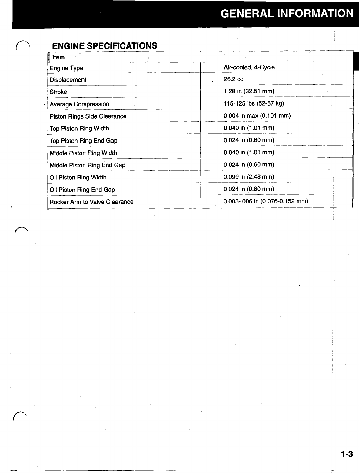
ENGINE SPECIFICAT IONS
FUEL AND LUBRICATION
IGNITION
TORQUE SPECIFICATIONS
TORQUE SPECIFICATIONS (CONT)
SAFETY WARNINGS AND NOTES
PRODUCT IDENTIFICATION NUMBERS
OIL AND FUEL RECOMMENDATIONS
STARTING/STOPPING INSTRUCTIONS
SERVICE/MAINTENANCE INSTRUCTIONS
STORAGE INSTRUCTIONS
TROUBLESHOOTING
ENGINE FAILS TO START
ENGINE STARVES ON ACCELERATION
ENGINE IS HARD TO START
ENGINE STALLS
ENGINE FIRES INTERMITTENTLY
ENGINE DOES NOT PRODUCE MAXIMUM POWER
CARBURETOR FLOODS
ENGINE STOPS AFTER RUNNING BRIEFLY
ENGINE WILL NOT IDLE
ENGINE BACKFIRES OR MISFIRES
ENGINE WILL NOT ACCELERATE
ENGINE LACKS POWER OR STOPS DURING OPERATION
ENGINE VIBRATES EXCESSIVELY
ENGINE USES EXCESSIVE AMOUNT OF OIL
STARTER ROPE IS DIFFICULT TO PULL OR ENGINE LOCKS
DISASSEMBLY
TYPICAL DISASSEMBLY SEQUENCE
REMOVE MAJOR COMPONENTS
DISASSEMBLE ENG IN E
INSPECTION AND REPAIR
CARBURETOR DISA SSEMBLY AND REASSEMBLY
STARTER DISASSEMBLY AND REASSEMBLY
BREATHER DISASSEMBLY AND REASSEMBLY
SPARK ARRESTER SCR EEN
PISTON/CONNECTING ROD DISASSEMBLY & ASSEMBLY
PISTON/CONNECTING ROD DISASSEMBLY & ASSEMBLY
CYLINDER HEAD INSPECTION & REPAIR
Page 2

AC-1 ENGINE SERVICE MANUAL
Table of Contents – Page 2 of 2
INSPECTION AND REPAIR - Continued
CRANKCASE INSPECTION & REPAIR
MAJOR COMPONENTS INSPECTION & REPAIR
REASSEMBLY
TYPICAL ASSEMBL Y SEQU E NCE
ENGINE REASSEMBLY
INSTALL AIR FILTER BASE, AIR FILTER AND AIR FILTER COVER
ASSEMBLE HANDLE
ASSEMBLE COV ERS
Page 3

Page 4
ABOUT THIS MANUAL
This Service Manual was written expressly for the Toro AC-1 Four Stroke Engine. The Toro Company has made
every effort to make the information in this manual complete and correct. We are hopeful you' find this manual a
If
valuable addition to your service shop.
please contact us at the following address:
you have any questions or comments regarding the information inside,
The Toro Company
Consumer Service Training Department.
81
11
Lyndale Avenue South
!
Bloomington, MN
55420
The Toro Company reserves the right to change product specifications or this manual without notice.
Copyright@
1996
The Toro Company
All
Rights Reserved
Page 5

General Information
.........................
B
Troubleshooting
Disassembly
Inspection and Repair ......................
Reassembly
.........................
..............................
...........................
.#
..
.,
..
.,
..
4
5
Page 6

Table
Of
Contents
Engine Specifications
Fuel and Lubrication
ignition
Torque Specifications
Safety Warnings And Notes
Product Identification Numbers
Oil And Fuel Recommendations
Starting/stopping Instructions
Service/maintenance Instructions
......................................
Recommended Oil Type
Checking the Oil
Changing the Oil
Recommended Fuel Type
Definition of Blended Fuels
Use of Blended Fuels
Use of Fuel Additives
To Start the Engine
To Stop the Engine
Air Filter
..................................
...............................
...............................
...............................
..............................
.............................
............................
............................
...........................
..........................
.........................
..........................
.........................
.........................
.
...........................
...........................
...........................
........................
1-3
1-4
1-4
1-4
1-6
1-7
1-7
1-7
1-8
1-9
1-9
1-9
1-9
1-9
1-10
1-10
1-11
1-11
1-11
Spark Plug
Carburetor Adjustment
Definition of Optimum Setting for Idle Speed Mixture and
High Speed Mixture Adjustments
Rocker Arm to Valve Clearance Adjustment
Spark Arrester Screen
Storage instructions
To Reactivate Unit for Service
Special Tools
...................................
................................
..........................
.....................
...............
..........................
...............................
.......................
1-12
1-12
1-15
1-15
1-16
1-17
1-17
1-18
1
-2
Page 7
j
Item
B
Engine Type
___
Displacement
~~
~~
~
~~
Air-cooled, 4-Cycle
Stroke
~__~
Average Compression
Piston Rings Side Clearance
~~-~___
Top Piston Ring Width
Top Piston Ring End Gap
Middle Piston Ring Width
_____~.
Middle Piston Ring End Gap
-
~ ~~
Oil Piston Ring Width
Oil Piston Ring End Gap
~____
Rocker Arm to Valve Clearance
~~~
~-
-~
~__
-
__~
__~_____--
_-
~~
-
_-
~~~
~
~-
~~
-~
~
__
~~
~~
1
-3
Page 8

11
Approx Fuel Tank Capacity
TORQUE SPECIFICATIONS
18
oz
(530
ml)
tem
Carburetor/Air Filter Base Plate Mounting Screws
~~~~~
Carburetor Mount Insulator Screws
~~
Clutch Housing/Drum Assembly Screws
_.
~ . ~
_~~_~~~-_____-~_--
-
--~__
~
~ ~~ ~
-
Clutch Rotor
Cylinder Head Hex Nuts
Cylinder Screws
Spark Plug
~
-.
~
-
-
.
-.
..
_.._..____
. .___
Rear Engine Cover Screw
Front Engine Cover Screws
~
.
.
.
~~
~~
__
~~
-
-
1-4
Page 9

Page 10
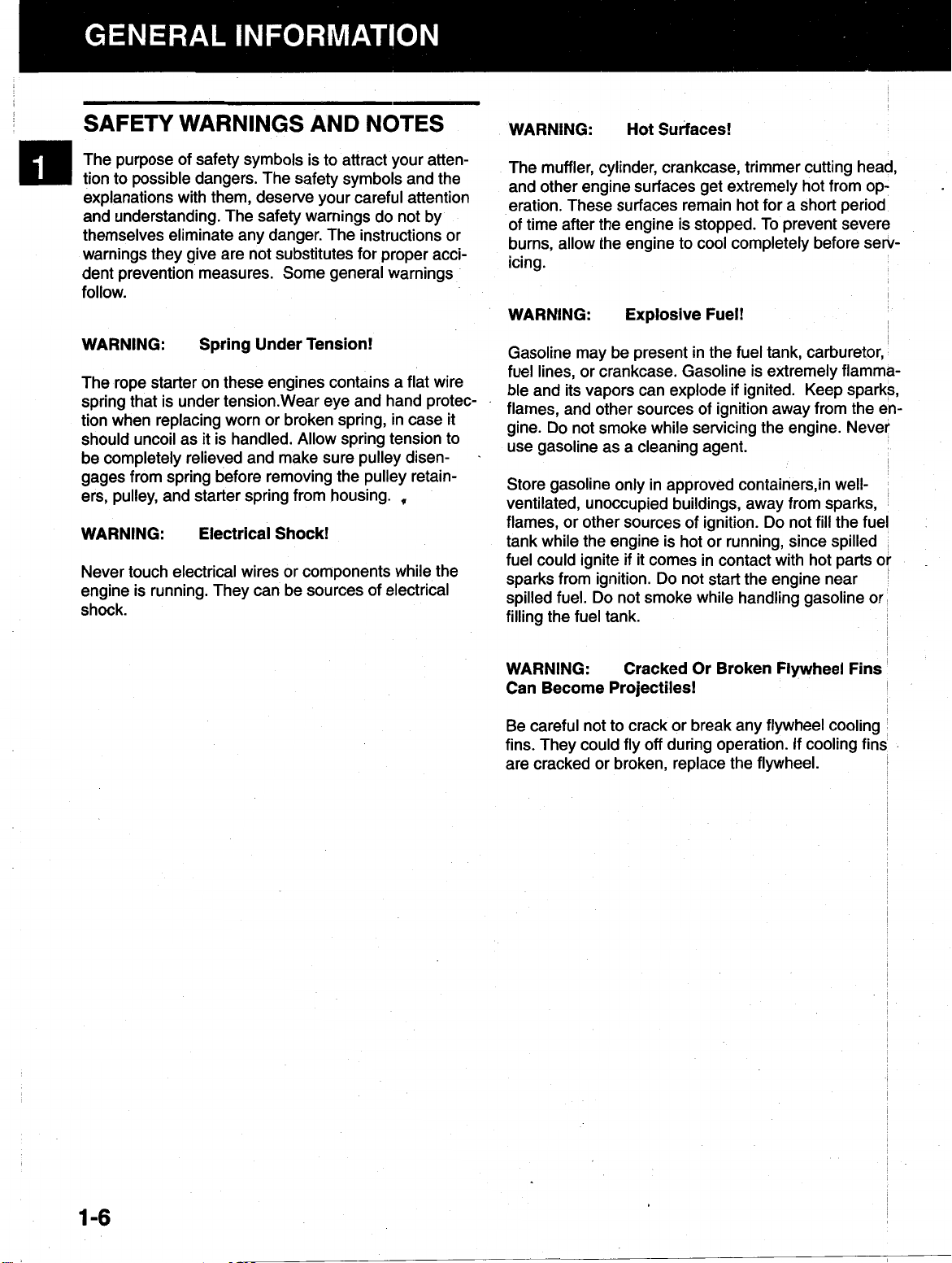
SAFETY WARNINGS AND NOTES
WARNING: Hot Surfaces!
The purpose of safety symbols is to attract your attention to possible dangers. The safety symbols and the
explanations with them, deserve your careful attention
and understanding. The safety warnings do not by
themselves eliminate any danger. The instructions or
warnings they give are not substitutes for proper accident prevention measures. Some general warnings
follow.
WARNING: Spring Under Tension!
The rope starter on these engines contains a flat wire
spring that is under tension. Wear eye and hand protection when replacing worn or broken spring, in case it
should uncoil as it is handled. Allow spring tension to
be completely relieved and make sure pulley disen-
.
gages from spring before removing the pulley retain-
ers, pulley, and starter spring from housing.
,
WARNING: Electrical Shock!
Never touch electrical wires or components while the
engine is running. They can be sources of electrical
shock.
The muffler, cylinder, crankcase, trimmer cutting head,
and other engine surfaces get extremely hot from operation. These surfaces remain hot for a short period
of time after the engine is stopped. To prevent severe
burns, allow the engine to cool completely before servicing.
I
WARNING: Explosive Fuel!
Gasoline may be present in the fuel tank, carburetor,
fuel lines, or crankcase. Gasoline is extremely flammable and its vapors can explode
if
ignited. Keep sparks,
flames, and other sources of ignition away from the engine.
Do
not smoke while servicing the engine. Never
use gasoline as a cleaning agent.
in
not
well-
fill
the fuel
~
Store gasoline only in approved containers,
ventilated, unoccupied buildings, away from sparks,
flames, or other sources of ignition.
Do
tank while the engine is hot or running, since spilled
fuel could ignite
sparks from ignition.
spilled fuel.
if
it comes in contact with hot parts
Do
not start the engine near
Do
not smoke while handling gasoline or
or
filling the fuel tank.
i
.
WARNING: Cracked Or Broken Flywheel Fins
Can Become Projectiles!
Be careful not to crack or break any flywheel cooling
fins. They could fly
off
during operation.
If
cooling fin:
are cracked or broken, replace the flywheel.
1
-6
Page 11

PRODUCT IDENTIFICATION
NUMBERS
When ordering parts, or in any communication involving an engine or product, always give the:
Model Number, and
Serial Number
NOTE:
BEFORE Attempting TO START
THIS UNIT. Using old oil or fuel can cause engine
damage. This type of damage will void the engine
warranty
READ
THESE INSTRUCTIONS
CAREFULLY
OR
OPERATE
These numbers are located on a decal (or decals) affixed to the unit (Figure 1-1). The identification de-
will be located on the metal boom. The actual
location will vary depending on the type of product.
Figure 1-1. Product Identification Decal
1.0762.005
.
OIL AND FUEL
RECOMMENDATIONS
Recommended Oil Type
Toro 4-cycle oil is recommended for use in this engine
(Figure 1-2).
high
quality SAE
troleum Institute) service class SG,
Using the proper type and weight of oil in the oil pan is
extremely important. Check the oil before each use
and change the oil regularly. Failure to use the correct
oil, or using dirty oil, can cause premature engine
wear and failure.
If
another brand 4-cycle oil is used, use a
30
weight oil of API (American Pe-
SF,
SH.
TORO,
FOUR-CYCLE
ENGINE
OIL
,.
WARNING: Explosive Fuel!
Gasoline
can explode if ignited. Store gasoline only in ap-
proved containers, in well-ventilated, unoccupied
buildings, away from sparks or flames. Do not fill
the fuel tank while the engine is hot or running,
since spilled fuel could ignite if
with hot parts or sparks from Ignition. Do not start
the engine near spilled fuel. Do not smoke while
handling gasoline. Never use gasoline as a cleaning agent.
Is
extremely flammable and its vapors
it
comes
in
contact
I--------
Figure 1-2. Recommended Oil Type.
3.6051.002
1
-7
Page 12

Checking the
Oil
The importance of checking and maintaining the
proper oil level in the oil pan cannot be overempha-
sized. Check the oil
1.
Make sure the engine is stopped, level and is cool
so
the oil has had time to. drain into the oil pan
(Figure
1-3
BEFORE EACH USE
as follows:
for straight shaft units or Figure
1-4
for curved shaft units).
1-3.
Figure
Figure
2.
To keep dirt, grass clippings, etc. out of the engine,
clean the area around the oil
Level Engine - Straight Shaft Unit.
1-4.
Level Engine - Curved Shaft Unit.
fill
plug before remov-
3.6051.020
3.6051.004
ing it.
3.
Remove the oil
into the crankcase. Thread the oil
fill
plug; wipe the oil
off.
Reinsert it
fill
plug into the
oil pan.
4.
Remove the oil
(Figure
1-5).
fill
plug and check the oil level
Figure
1-5.
Removing Oil Fill Plug.
2.6051.005
The oil level should be up to the top of the dipstick
(Figure
1-5).
Full
(3.40z/lOOml)
Add Oil
L
Figure
5.
1-6.
Oil Level
If
the oil level is low, add the oil to the top
the dipstick (see Figure
3.6051.006
1-6).
Always check the
of
level with the dipstick before adding more oil.
1
-8
Page 13
Changing the Oil
For a new engine, change the oil after the
hours
every
of operation. Thereafter, change the oil after
25
hours
or before storing the unit for an ex-
tended period of time.
first
10
NOTE:
To prevent extensive engine wear or damage,
always maintain the proper oil level in the crankcase.
Never operate the engine with the oil level below the
bottom of the dipstick
Recommended Fuel Type
Change the oil while the engine is still warm. The oil
will flow freely and carry away more impurities.
Change the oil as follows:
1.
Remove the oil
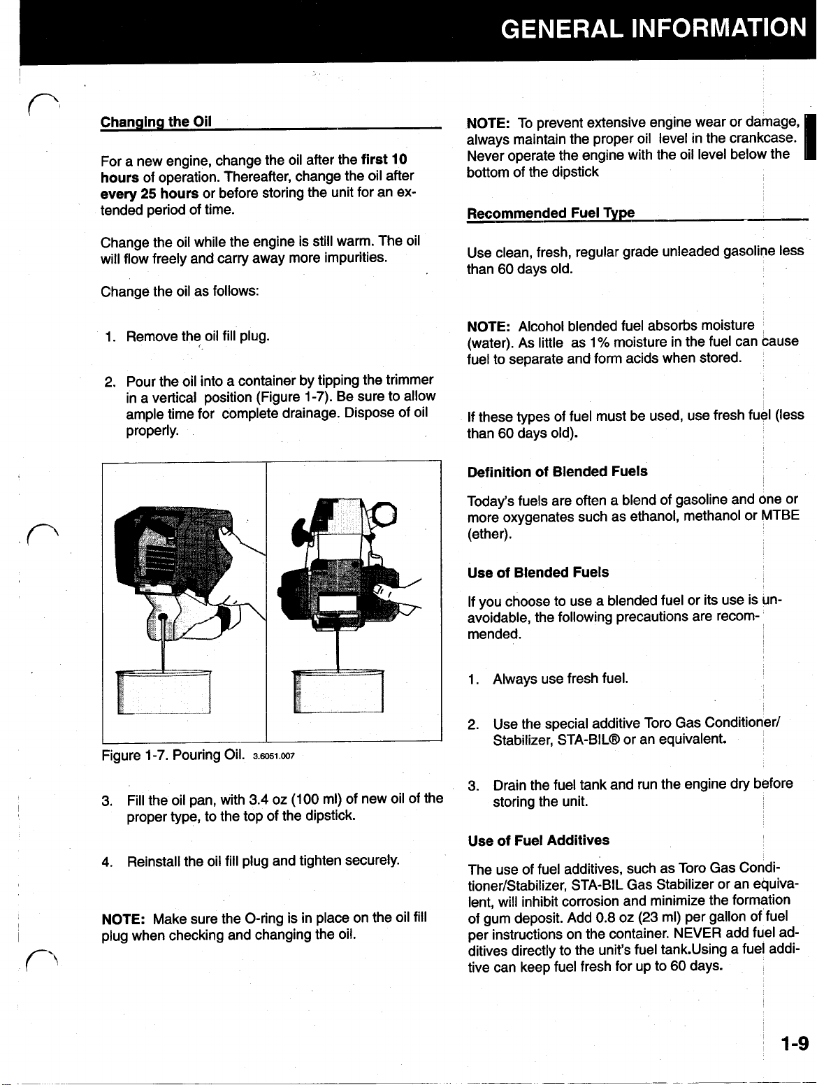
2. Pour the oil into a container by
in a vertical position (Figure
fill
plug.
tipping the trimmer
tipping
7).
Be sure to allow
1-7
ample time for complete drainage. Dispose of oil
properly.
Use clean, fresh, regular grade unleaded gasoline less
than
60
days old.
NOTE:
(water). As little as
Alcohol blended fuel absorbs moisture
1
%
moisture in the fuel can cause
fuel to separate and form acids when stored.
If
these types of fuel must be used, use fresh fuel (less
than
60
days old).
Definition
of
Blended Fuels
Today's fuels are often a blend of gasoline and one Or
more oxygenates such as ethanol, methanol or MTBE
(ether).
Use of Blended Fuels
If
you choose to use a blended fuel or its use is un-
avoidable, the following precautions are recom-
mended.
1-7.
Figure
Pouring Oil.
3. Fill the oil pan, with 3.4 oz
3.6051.007
(100
ml) of new oil of the
proper type, to the top of the dipstick.
4.
Reinstall the oil
NOTE:
Make sure the O-ring is in place on the oil
fill
plug and tighten securely.
plug when checking and changing the oil.
fill
1.
Always use fresh fuel.
2. Use the special additive Toro Gas Conditioner/
Stabilizer, STA-BIL
(R)
or an equivalent.
3. Drain the fuel tank and run the engine dry before
storing the unit.
Use of Fuel Additives
The use of fuel additives, such as Toro Gas Conditioner/Stabilizer, STA-BIL Gas Stabilizer or an equiva-
lent, will inhibit corrosion and minimize the formation
of gum deposit. Add
0.8
oz (23 ml) per gallon of fuel
per instructions on the container. NEVER add fuel ad-
ditives directly to the unit's fuel tank. Using a fuel addi-
60
tive can keep fuel fresh for up to
days.
1-9
Page 14
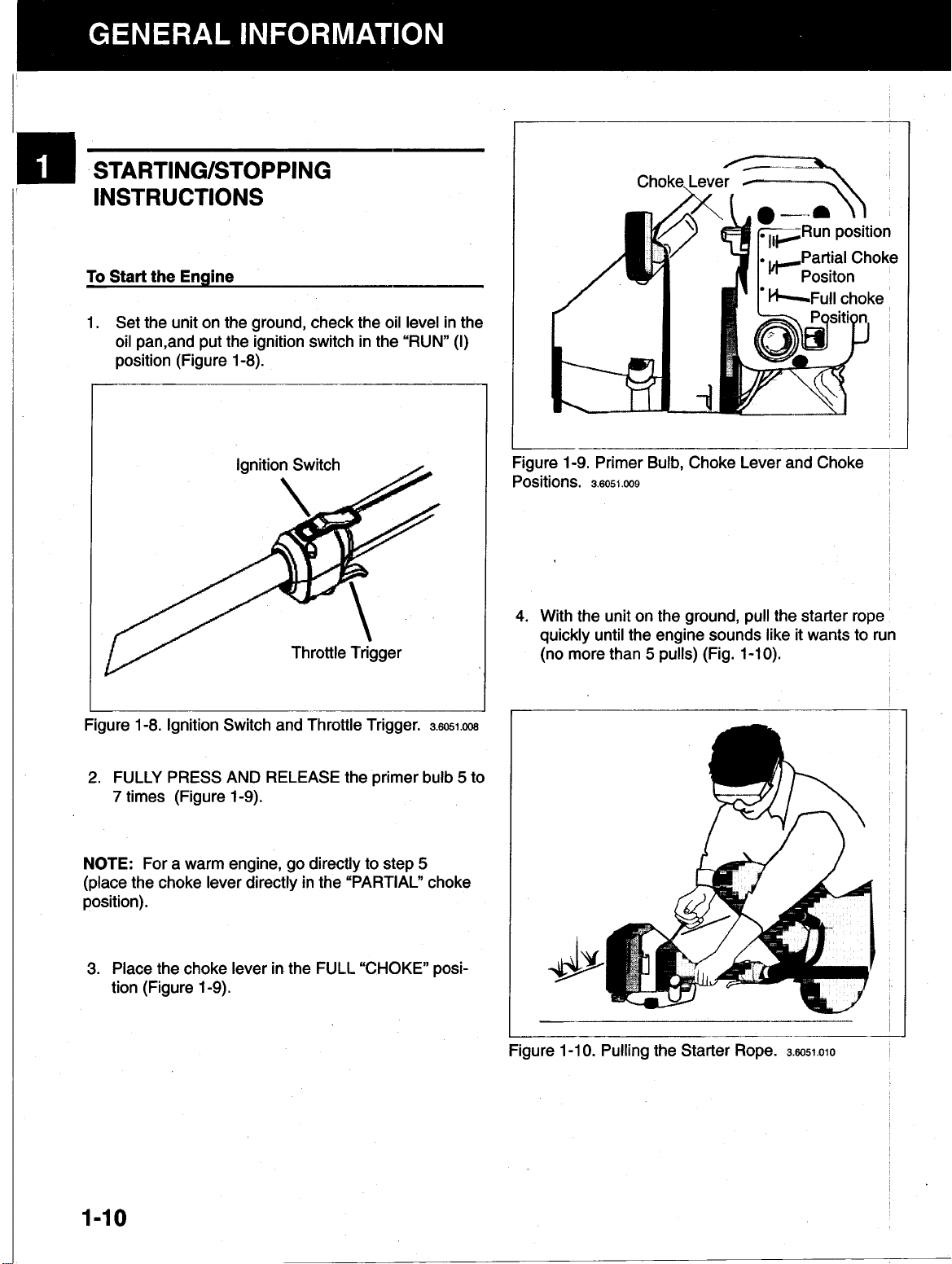
STARTING/STOPPING
INSTRUCTIONS
To
Start
the Engine
1.
Set the unit on the ground, check the oil level in the
oil pan, and put the ignition switch in the “RUN”
position (Figure 1-8).
---Run position
Partial Choke
choke
(I)
Figure 1-8. Ignition Switch and Throttle Trigger.
2.
FULLY PRESS AND RELEASE the primer bulb 5 to
7
times (Figure 1-9).
NOTE:
For a warm engine, go directly to step
3.6051.008
5
(place the choke lever directly in the “PARTIAL” choke
position).
Figure
Positions.
1-9.
Primer Bulb, Choke Lever and Choke
3.6051.009
4.
With the unit on the ground, pull the starter rope
quickly until the engine sounds like it wants to run
5
(no more than
pulls) (Fig. 1-10).
,
3.
Place the choke lever
tion (Figure 1-9).
1-10
in
the FULL “CHOKE” posi-
Figure 1-1
0.
Pulling the Starter Rope.
3.6051.010
Page 15

5.
Place the choke lever in the “PARTIAL” choke position (see Figure 1-9 on page 1.4). Pull the starter
rope quickly until the engine starts (no more than
5
pulls).
6.
If
the engine does not start, repeat steps 2 to 8.
7.
Run the engine for
lever fully squeezed (see Figure 1
30
seconds, with the throttle
-6),
to warm up.
Place the choke lever in the “RUN” position
(Figure 1-9).
2.
Wash the air filter in detergent and water
(Figure 1-11). Rinse the air filter thoroughly in
clean water and allow
it
to dry.
NOTE:
In colder weather, run the engine for 2 to
3
minutes to warm up.
To
Stop the Engine
Place the ignition switch in the “STOP position (see
Figure 1-8).
SERVICE / MAINTENANCE
INSTRUCTIONS
Air Filter
NOTE:
CLEAN AND
EVERY 10 HOURS
one of the most important areas to maintain.
maintained as follows, poor engine performance and
severe engine damage can result.
1. Remove the three
filter cover assembly. Remove the air filter cover
and air filter. Refer to
RE-OIL
OF
(3)
THE
AIR
FILTER
OPERATION. The air filter is
screws on the carburetor/air
Part
3
-
Engine
Disassembly
\
If
it is not
L
Figure 1-1 1. Washing Air Filter Element.
3.
Apply clean SAE
Figure 1-1
2.
Oiling Air Filter Element.
30
oil to the air filter (Figure 1-12).
3.6051.012
3.6051.011’
I
I
4. Squeeze the air filter to ensure that the oil is spread
throughout the entire filter (Figure 1-13).
1-11
Page 16

L
Figure 1-13. Squeezing Excess Oil from Air Filter
Element.
5.
Spark Plug
3.6051.013
Reinstall the air filter in the carburetor/air filter
base. Refer to
Part
5
-
Engine Reassembly
NOTE:
Do not clean the spark plug in a machine
~
which uses abrasive grit. Some grit could remain on
the spark plug and enter the engine causing extensive
damage.
4. Check the spark plug gap using a wire feeler gauge.
Set the gap to
5.
Reinstall the spark plug and torque to
(1 1.3-1 2.3
0.025 in
N-m).
(0.635
mm)(Figure 1-14).
100-110 in-lb
Use a Champion RDZ19H spark plug. Every 50
hours
of operation, remove the spark plug, check its condition, and reset the gap or replace with a new plug as
necessary. Allow the engine to cool before removing
the spark plug.
WARNING: Electrical Shock!
Never touch electrical wires or components while the
engine is running. They can be sources of electrical
shock.
1. Before removing the spark plug, clean the area
around the base of the spark plug to keep dirt and
debris out of the engine.
2.
Disconnect the spark plug wire and remove the
spark plug from engine.
3.
Inspect the spark plug for carbon buildup and clean
if
necessary. Replace the plug
if
reuse is questionable.
if
it is badly burnt or
Figure 1-14. Spark Plug Gap.
Carburetor Adjustment
3.6051.014
-
These engines are equipped with a diaphragm-type
carburetor. The carburetor has been carefully cali-
~
brated at the factory. In most cases, no further adjustment will be required.
The condition of the air filter is very important to the
(
eration of the trimmer. A dirty air filter will restrict the
air flow to the carburetor. This in turn upsets the fuelair mixture in the carburetor. The resulting symptoms
are often mistaken for an out-of-adjustment carburetor
Therefore, check the condition of the air filter before
adjusting the carburetor. Refer to “Air Filter“ Service/Maintenance Instructions.
I-
1-12
-
Page 17

If
the following conditions are experienced, it may be
necessary to adjust the carburetor.
The engine will not idle
The engine hesitates or stalls on acceleration.
The
loss
of engine power, which is not corrected
by cleaning the air filter, muffler, spark arrester
screen or adjusting the rocker arm to valve
clearance
The engine operates in an erratic or fuel-rich
condition
NOTE:
Follow these carburetor adjustment procedures carefully. An incorrectly adjusted carburetor can
cause severe engine damage.
407000001-Use the following carburetor adjustment
instructions:
1.
Initial Idle Speed Setting:
Turn the idle speed
screw until it stops.
2.
Initial High Speed Mixture and Idle
ture Settings:
and idle mixture needles
Turn both the high speed mixture
in (clockwise)
Speed
until they
Mix-
are lightly seated.
3.
Turn the needles
following number
out
of
turns:
the
High Speed Mixture Needle: 1 turn
Idle Speed Mixture Needle:
1
turn
Make sure the unit is fully assembled before
making carburetor adjustments.
For trimmers
and
brushcutters, make sure
the boom, cutting head, and line guard are installed
and the cutting line is extended to its full cutting length.
The carburetor has three basic adjustments: the idle
speed adjustment, the idle speed mixture adjustment,
and the high speed mixture adjustment (Figure 1-15).
Mixture Needle
NOTE:
Turn the high speed mixture and idle mixture
needles finger-tight. Do not force the needles with a
screwdriver as this can damage the tips of the needles
and the seats in the carburetor body.
4. Start the engine and let it run for
3
to 5 minutes
with the throttle lever fully squeezed.
5.
Release the throttle trigger and let the engine idle.
Turn the idle speed screw
until the speed decreases and the bump
wise)
out (counterclock-
head stops rotating.
6.
Final Idle Speed and Mixture Adjustments:
Adjust the idle speed screw and idle speed mixture needle for the smoothest engine idle using
Do
the following procedure.
not squeeze throttle
trigger when adjusting the idle speed screw and
idle speed mixture needle.
a. Set the idle speed mixture needle
at the optimum setting
(Figure 1-16). See “Definition of Optimum
Setting” on page
1-1
5.
Figure
1-1
5.
Carburetor Adjustments.
3.6051.015
1-13
Page 18

b
b. Squeeze the throttle trigger.
falters or hesitates as
idle speed mixture needle
wise) 1/16 turn at a time
celerates rapidly.
it
If
the engine
accelerates, turn the
out (counterclock-
until the engine ac-
3.
Turn the needles
following number of turns:
High Speed Mixture Needle: 1 1/8 turns
out (counterclockwise)
the
c.
If
the idle speed has changed significantly because of steps a. and b. above, readjust the
idle speed screw.
7.
Final High Speed Mixture Setting:
Adjust the high speed mixture needle as follows:
a. Squeeze the throttle trigger and
run the unit at high speed for
b. While squeezing the throttle trigger fully, set
the high speed mixture needle at the optimum
setting. See “Definition of Optimum Setting”
on page 1-1 5.
NOTE:
must be the last adjustment made
the idle speed mixture needle is adjusted, the high
speed mixture needle must be readjusted.
8.
For Units with Engine Serial Number 407000001
and Greater-Use
ment instructions:
The high speed mixture needle adjustment
Make sure the air filter cover is reinstalled securely
before placing the unit back into service.
the following carburetor adjust-
3
to 5 minutes.
on
the carburetor.
Idle Speed Mixture Needle1 1/8 turns
NOTE:
mixture needles using finger pressure. Forcing the mixture needles will damage the tips of the needles and
the seats in the carburetor body.
4.
5.
6.
If
NOTE:
justment is made, no more high speed mixture needle
adjustments to the carburetor are necessary.
Seat the high speed mixture and idle speed
Start the engine and let it run for 3 to 5 minutes
with the throttle lever fully squeezed.
Release the throttle trigger and let the engine idle.
If
the engine stops, turn the idle speed screw
(clockwise) 1/8 turn
the engine idles.
Final High Speed Mixture Needle Adjustment:
a. While squeezing the throttle trigger fully, set
the high speed mixture needle at the optimum
setting. See “Definition of Optimum Setting”.
After the final high speed mixture needle ad-
at a time (as required) until
in
~
1.
Initial Idle Speed Setting:
screw (Figure 1-15)
it
does not contact
Then turn the screw
gins
to move the throttle lever; then continue turn-
ing
2
full turns.
2.
Initial High Speed Mixture and idle Speed
Mixture Settings:
ture and idle speed mixture needles
wise)
until they are
out (counterclockwise)
the carburetor throttle lever.
in (clockwise)
Turn both the high speed mix-
lightly seated.
Back the idle speed
1-14
until it
just be-
in (clock-
until
7.
Final Idle
Adjustments:
idle speed mixture needle for the smoothest engine idle using the following procedure. Do not
squeeze the throttle trigger when adjusting the idle
speed screw and idle speed mixture needle.
a. Set the idle speed mixture needle at the
b. Turn the idle speed mixture needle
Speed
optimum setting (Figure 1-16). See “Definition’
of Optimum Setting”.
(counterclockwise) 1/8 turn
of optimum.The engine should idle and accelerate smoothly.
and Idle Speed Mixture
Adjust the idle speed screw and
out
to the rich side
’
~
~
~
Page 19

8.
Final Idle Speed Adjustment:
speed by turning the idle speed screw
wise)
or
out (counterclockwise)
head does not rotate.
Do
Adjust the idle
in (clock-
until the cutting
not squeeze the throttle
trigger when adjusting the idle speed screw.
9.
Make sure the air filter cover is reinstalled securely
before placing the unit back into service.
Definition of Optimum Setting for Idle Speed
Mixture and High Speed Mixture Adjustments
Always set the idle speed mixture needle and high
speed mixture needle at the optimum setting. To find
the optimum setting, use the following procedure.
1. Turn the adjusting needle
out (counterclockwise)
from the preliminary setting until the engine speed
decreases (rich). Note the position of the needle.
2.
Turn the adjusting needle
in (clockwise).
The engine speed may increase as the needle is turned
in (lean). Note the position of the needle.
Rocker Arm to Valve Clearance Adjustment
50
hours
Every
of operation, remove the rocker
arm
cover and check the rocker arm to valve clearance.
1.
Remove the four
(4)
screws from the engine cover.
Remove the engine cover. Remove the rocker arm
cover. Refer to
2.
Position the crankshaft
Part
3
-
Engine Disassembly.
so
that the piston is at the
top of the compression stroke (both rocker arms
are free and loose).
3.
Measure the clearance between the valve stems
and rocker arms, using a
1-17).
flat
feeler gauge (Figure
3.
Set the adjusting needle
midway
and the lean settings (Figure 1-16).
Adjust to
Midpoint
Figure 1-16. Optimum Setting.
3.6051.016
between the rich
Lean
I
Figure 1-17. Measuring the Rocker Arm to Valve
Clearance.
3.6051.017
The recommended rocker arm to valve clearance for
both the intake and exhaust is
(.076
mm-,152 mm).
.003-.006
in
Page 20

4.
If
the clearance is not within specification, adjust as
follows:
Spark Arrester Screen
b
To
the adjusting nut counterclockwise.
To
the adjusting nut
5.
a. Turn the adjusting nut (Figure 1-18), using a
5/16 in (8 mm) wrench or nut driver.
increase the rocker arm to valve clearance,
decrease the rocker arm to valve clearance,
clockwise.
b. Recheck the clearance with a flatfeeler gauge
and readjust as necessary (see Figure 1-1
Reinstall the rocker arm cover, using a new gasket.
Torque the rocker arm cover screw to
(2.2-3.4 N.m).
20-30 in-lb
turn
turn
7).
This unit is equipped with a spark arrester screen.
50
hours
Every
screen for debris and/or deposits.
WARNING: Hot Surfaces!
Make sure the muffler is cool before checking the
spark arrester screen to prevent injury.
1. Remove the spark arrester cover screw and cover
(Figure 1-1
of operation, check the spark arrester
9).
Figure 1-18. Adjusting Nuts.
6. Install the breather hose to the air filter base.
7.
Reinstall the engine cover and screws. Refer to
Part
5
-
Engine Reassembly.
Torque the top screws to
Torque the front screw to
Torque the rear screw with washer to
4.0
Nom).
2.6051.018
15-20 in-lb (1.7-2.2 Nom).
20-25 in-lb (2.2-2.8 Nom).
30-35 in-lb (3.5-
1-16
Figure 1-1
2.
3.
4.
9.
Spark Arrester Screen.
Push the spark arrester screen out of the cover.
Inspect the spark arrester screen.
If
the screen is clean, reinstall the screen,
cover and screw.
replace it.
Torque the screw to
If
the screen is plugged,
15-20 in-lb (1.7-2.2 N-m).
3.6051.019
Page 21

STORAGE
WARNING: Explosive Fuel!
Gasoline is extremely flammable and its vapors can
explode if ignited. Store gasoline only in approved containers, in well-ventilated, unoccupied buildings, away
from sparks or flames. Do not
the engine is hot or running, since spilled fuel could
if
ignite
from ignition. Do not start the engine near spilled fuel.
Do not smoke while handling gasoline. Never use
gasoline as a cleaning agent.
1.
2.
3.
it comes in contact with hot parts or sparks
Drain all fuel from the fuel tank.
that has been stored for more than
Start the engine and run it until it stalls. This
ensures that all fuel has been drained from the
carburetor.
Drain the oil from the crankcase and add fresh oil
(3.4
oz
to lubricate the engine.
INSTRUCTIONS
fill
the fuel tank while
Do
not use fuel
60
/100
ml). Pull the starter rope a few times
days.
Figure
To
1.
2.
3.
1-21.
Storing a Curved Shaft Unit.
Reactivate Unit for Service
Remove the spark plug and drain the oil from the
cylinder by slowly pulling the starter rope.
Reinstall the spark plug.
Refuel the unit with fresh gasoline. Start engine in
accordance with the
Starting Instructions.
3.6051.021
4.
Allow the engine to cool. Remove the spark
plug and put several drops of any
30
quality SAE
Petroleum Institute) service class SG,
into the cylinder. Pull the starter rope slowly to dis-
tribute the oil. Reinstall the spark plug.
5.
Clean the unit and inspect for any loose or
damaged parts. Repair or replace damaged parts
and tighten loose screws, nuts, or bolts.
6.
Store the unit in a 'dry, well ventilated area. Place
unit
the
for straight shaft units or Figure
shaft units).
flat on the floor or on a table (Figure
weight oil of API (American
high
1-21
SF,
for curved
SH
1-20
Figure
1-20.
Storing a Straight Shaft Unit.
3.6051.020
Page 22
~
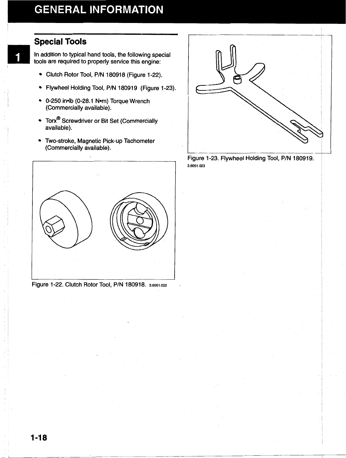
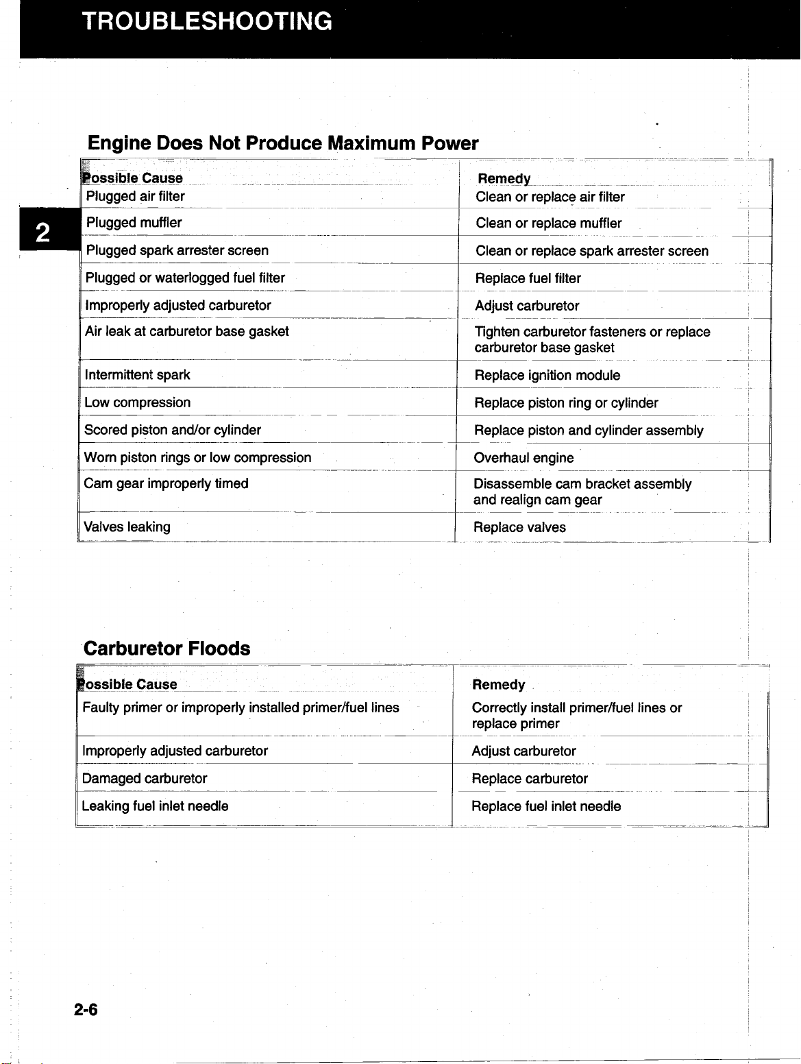
Special
Tools
In addition to typical hand tools, the following special
tools are required to properly service this engine:
Clutch Rotor
Flywheel Holding
Tool,
P/N 180918 (Figure 1-22).
Tool,
P/N 180919 (Figure 1-23).
0-250 in-lb (0-28.1 N.m) Torque Wrench
(Commercially available).
Toro (R)
Screwdriver or Bit Set (Commercially
available).
Two-stroke, Magnetic Pick-up Tachometer
(Commercially available).
Figure 1-23. Flywheel Holding Tool, P/N 18091 9.
3.6051
.023
Figure 1-22. Clutch Rotor
1-1
8
Tool,
P/N 180918.
3.6051.022
Page 23

General Information
.
...........................
.
Troubleshooting
Disassembly
Inspection and Repair
Reassembly
......
......
. .
.
...........................
...........................
............................
2.
5
2-1
Page 24

Table
Of
Contents
Engine Fails
Engine Starves On Acceleration
Engine
Engine Stalls
Engine Fires Intermittently
Engine Does Not Produce Maximum Power
Carburetor
Engine Stops After Running Briefly
Engine Will Not Idle
Engine Backfires
Engine Will Not Accelerate
Engine Lacks Power Or Stops During Operation
Engine Vibrates Excessively
Engine Uses Excessive Amount Of Oil
Starter Rope
Is
Hard
To
Start
...............................
.........................
To
Start
..............................
....................................
.............................
Floods
.................................
........................
................................
Or
Misfires
...........................
............................
...........................
......................
Is
Difficult
To
Pull Or Engine Locks
...................
2-8
.................
.................
2-8
2-9
2-9
2-9
2-3
2-4
2-4
2.5
2-5
2-6
2-6
2-7
2-7
2-7
2-2
Page 25

c’
When difficulties occur, be sure to check for simple
causes which, at first, may seem too obvious to be
considered.
A
starting problem, for example, could be
caused by an empty fuel tank.
The following table lists some common causes of
operating troubles and the possible causes and
remedies.
I
-
Engine Fails
__
~-
;Possible
L-
Ignition switch in STOP
-~
~_~~~___
~-
~~ ~
Cause
To
.-
~~
_____
Start
~-
_
~.
(0)
position
_
.
~~ ~
-
-
___
~~
~-__
Out of fuel or water in fuel
~~
-___
Dirty or plugged air filter
Loose spark plug lead wire
__~____~
-
.-
~
Fouled, improperly gapped or broken spark plug
__~._
Plugged fuel tank cap vent
Plugged or waterlogged fuel filter
-
~_____~
Improperly adjusted carburetor
____-
Plugged muffler
-
Faulty primer or primer/fuel lines improperly installed
~.
-
-.
Plugged fuel line
Faulty carburetor diaphragm
____
Plugged spark arrester screen
Faulty fuel pump diaphragm
-
~.
_____
~~
.__
~-
-
_____
__
-
Plugged carburetor/fuel pump passages
&
Incorrect air gap between flywheel
ignition module
__
Faulty ignition module
Low
compression
_________~.~
.~
Rocker arm to valve clearance is out of adjustment
_~_____~_
___.
~~ ~~
~.__________
-
~-
~ ~~
-
i
~~ ~ ~
-~
~~~ ~~ ~
~
~-
__
-
__
~~
-_
Remedy
Place switch in
~
RUN
(I)
position
-~~
Drain tank and blow out fuel lines to remove water
Refuel tank with fresh fuel
-_
Clean or replace air filter
Reconnect lead wire
.~____
____
~
___~~
~-____
Clean or replace spark plug; set gap to 0.025 inch
(0.635
Clean fuel tank cap vent
Replace fuel filter
Adjust carburetor
mm)
__
~-
~-
~.-~____-~
~~
__
-~
~-
__
__~-
.-
~-
Clean or replace muffler
Correctly install primer/fuel lines or replace primer
~
____~.._~_.________
Blow out fuel line
Replace diaphragm
~~
Clean or replace spark arrester screen
Replace pump diaphragm
~~~ ~
Clean out passages
__
~.
~~~
-.
~~
.~
~~
~-
~
Set ignition module air gap to
0.008-0.01
-
Replace ignition module
_~_____
Replace piston rings or cylinder
_
2
in (0.201
.-
~~~~
-0.305
__
mm)
~-
--
Adjust rocker arm to valve clearance
___
~ ~~~
~
_
_~_
~_ _~
~-
~-
~ ~
__
-
~ ~~ ~
__
-~
8.
~~ ~
~-
~__
____
~-
~
I-
____
__
I
_~
~-
__
2-3
Page 26

1
8
Engine
possible
.
Cause
Is
Hard
To
~___~~
Start
~~
Fouled, improperly gapped or broken spark plug
Plugged or waterlogged fuel filter
___.
-
Improperly adjusted carburetor
Clogged muffler
~~
Faulty primer or primer/fuel lines improperly installed
~~
Incorrect air gap between flywheel and ignition module
-
Faulty ignition module
Plugged spark arrester screen
~-
.~
~
Rocker arm to valve clearance is out of adjustment
Worn or improperly adjusted carburetor jet needle
Faulty carburetor diaphragm
Faulty fuel pump diaphragm
~~
-
~~
__
__
..
~
.~
-
~~
-
~
-
~.
_____~~~
_____
~
-~
~
________
Low compression
_
-~
~~~~ ~
.
~~~
___
~ ~~ - ~
Remedy
-
~~
~ ~ ~~ ~
Clean or replace spark plug;
~~
set gap to 0.025 inch
~~~
Replace fuel filter
Adjust carburetor
Clean or replace muffler
_-
-
_
~~____~-~
~ ~~ ~ ~~~
~
-~
~
(0.635
mm).
~
Correctly install primer/fuel lines or
replace primer
~-
Set ignition module air gap to
0.008-0.01 2 in (0.201
Replace ignition module
___~_~~
Clean or replace spark arrester screen
_____~
_____~
~-
~_
Adjust rocker arm to valve clearance
_
Adjust or replace needle
~
Replace carburetor diaphragm
_
-
Replace fuel pump diaphragm
..
~ ~ ~
~~
~~~~~
_
~~ ~
~_-
-0.305
~~
_
~~~ ~ ~
_~
mm)
~ ~
___________~~~
Replace piston rings or cylinder
~
.
_-
~~~
___~_~_____~_~
-.
.
~
-
-
~-
.~
~
.~
~
_
~~
I
~
-
,
___
~ ~
~
~
_____
2-4
Page 27

Engine Stalls
Plugged fuel tank cap vent
Improperly adjusted carburetor
Plugged muffler
Plugged spark arrester screen
Plugged fuel line
-
Faulty ignition module
___-
-
__~
~-
~
-~
.~___
~
-_
Clean or replace spark plug; set gap to
0.025
inch
-
-.
~~
(0.635
Clean fuel tank cap vent
Adjust carburetor
mm)
~
_.
_.
~-
__
_.
Clean or replace muffler
~
~-
~~ ~~
Clean or replace spark arrester screen
Blow
out fuel line
Replace ignition module
____
~
~
~-
~-
~
--~
~-
~
-~
__
-___
~
~
--
-
__~
~-
Engine Fires Intermittently
Fouled, improperly gapped or broken spark plug
____-
incorrect air gap between flywheel and ignition module
improperly adjusted carburetor
~ ~
-~
Faulty ignition module
-
~
__---
Remedy
~ ~~
Clean or replace spark plug; set gap to
0.025
inch
--
~
(0.635
mm).
-~___
Set ignition module air gap to
0.008-0.01
~~
Adjust carburetor
Replace ignition module
~-
~ ~~~
2
in
______~
____
--
(0.201
-.
-
~ ~~ ~
-0.305
~-
__
mm))
-
2-5
,
Page 28
Engine Does Not Produce Maximum Power
Plugged muffler
Plugged spark arrester screen
Plugged or waterlogged fuel filter
-.
..
~
~ ~ ~~~ ~
~~ ~~~~ ~ ~~~
Improperly adjusted carburetor
Air leak at carburetor base gasket
Intermittent spark
Low compression
Scored piston and/or cylinder
._
~ ~~ ~
~p
~ ~
..
-
.
.
Worn piston rings or low compression
Cam gear improperly timed
Valves leaking
~~~
~_~
~.
~~
~ _ ~
__
~
Carburetor
Floods
pp~_~
~~~ ~~~
ulty primer or improperly installed primer/fuel lines
_. . .
.
.. . ...
~
11
Damaged carburetor
Leaking fuel inlet needle
11
~.
2-6
~~~
~~~~ ~
I
Remedy
.
. .
~_
Page 29

Engine
_~_____.
possible Cause
i
Stops
~__~~
~~~~
After Running Briefly
-~
~ ~~
Partially plugged fuel tank cap vent
Dirty or plugged air filter
Water in fuel
________
~~
Air leak at carburetor base gasket
Dirty carburetor fuel inlet needle or passage
~~
__
Faulty carburetor diaphragm
_______~~
-~
-~__
~
~~
~~___~~~__
Clean or replace air filter
~.
~~
__
Drain tank and blow out lines
~~~~
~~__
Tighten carburetor mounting fasteners or
replace carburetor base gaskets
-
-~
~~ ~
__~_
Replace fuel inlet needle or clean out carburetor
_-.___~.________
~~.~~_____~-
~___~~-~
Replace diaphragm
~
~~
~-
Losing compression
Engine
Possible g Cause
__~
Improperly adjusted carburetor
___~~________
Dirty or plugged air filter Clean or replace air filter
Faulty carburetor diaphragm Replace carburetor diaphragm
Faulty carburetor inlet seat gasket Replace carburetor inlet seat gasket
Will
~ ~
Not
Idle
~ ~~ ~~ ~~ ~~
~___
~______________~
Leaking crankshaft seal Replace crankshaft seal
Scored cylinder or low compression
____
i
~~1
-_
~ ~ ~
-
.-~.____._~
-$
.__~__
I
I
Replace piston rings or gaskets or
overhaul engine
___________-__
~~~ ~
~-
Remedy
~~ ~~~ ~~ ~~~ ~~
Adjust carburetor
~~
~~
________
__
~~
~~-.
-~
~ ~
-
.~
-
~__
~____-~
~-
~
~-
~
-
Overhaul engine
--
~-
~-
__
~
Engine Backfires Or Misfires
possible Cause
~
~
~-
~
Fouled, improperly gapped or broken spark plug
.
.___
Shorted ignition module leads
Rocker arm to valve clearance is out of adjustment
-
Weak valve spring
,__-
~~
-
~. _____.~~
~ ~
___~
~~
~
~-
~~
Check for loose or bare wires or loose
assembly and corrector replace ignition module
Adjust rocker arm to valve clearance
-_
-
-~
~___
-
Replace valve spring
~~~~ ~
2-7
Page 30

Plugged muffler Clean or replace muffler
~
__~~
~___~
Plugged spark arrester screen
Carburetor diaphragm gasket leaking
~~
~~__
.
~~__
0.025
inch(0.635 mm)
~
Clean or replace spark arrester screen
~~
.~
~~ ~
.
~~ ~ ~ ~~~~~ ~
Replace gasket
-
~~
Faulty primer bulb causing flooding
Dirty or plugged air filter
Plugged muffler
Plugged spark arrester screen
~-
Rocker arm to valve clearance is out of adjustment
Scored cylinder or low compression (below
. . .
. .
.
-
~
.-.~
-
~~~~~~
~
__~~
~~ ~~~ ~
~
-~
.
~~~____
~~ ~~
~___
~
90
~
psi)
Replace primer bulb
.-
-_
Clean or replace air filter
-
Clean or replace muffler
.
Clean or replace spark arrester screen
-
~
Adjust rocker arm to valve clearance
~~~__
~____._____~~
~~
.-
~ ~ ~~~~ ~ ~ ~
~~~~ ~ ~ ~ ~~
__~
~
~
~-
-
-~
~~ ~~~ ~
~~ ~~
I
..
Overhaul engine
2-8
Page 31

I
Oil
fill
plug loose or O-ring is leaking oil
-~
Breather housing plugged or damaged,
___-
..~~
Gaskets damaged or gasket surfaces nicked
-
Valve guides worn excessively
__
..
Cylinder wall worn or glazed
Piston rings and grooves worn excessively
.
.____.
-.
..
Piston fit undersized
~
Starter Rope
Oil
accumulated in combustion chamber
Is
Difficult
To
Pull Or Engine Locks
Replace O-ring and tighten oil
I
~~
Replace
breather housing assembly
__~
fill
plug
smooth gasket surfaces;
~
...
1
Replace cylinder head assembly
~
use new gaskets
~.
Replaced cylinder
piston rings and/or piston
,
1
Measure
-~
~~ ~~~~ ~
~~__-
1.
Remove the spark plug
2.
Drain the oil from the spark plug opening
and replace piston
__~
~~
~____
~~
__~
__
~
~__.~
~_i~~
if
necessary
~ ~~~
3.
Pull the starter rope several times to
remove any excess oil from the cylinder
excess oil with a dry cloth
5.
Reinstall the spark plug
2-9
Page 32

General Information
. .
.........
Troubleshooting
Disassembly
Inspection and Repair
Reassembly
....
.....
.....
.
.
.
.
.........
.........
.
.
.........
..........
3
3-1
Page 33

Table
Of
Contents
Typical Disassembly Sequence
Remove Major Components
Remove Engine
Remove The Spark Plug Wire And Spark Plug
Remove Upper Handle
Remove Lower Handle
Remove Air Filter
Remove Air Filter Base. Primer Bulb And
Carburetor
Remove Primer Bulb
Remove Engine Cover
Remove Carburetor Mount Insulator
Remove Intake Baffle
Remove Muffler
Remove Clutch
Remove Starter Module Assembly
..............................
.................................
...............................
..............................
..........................
...........................
..............
..........................
..........................
.............................
...........................
..........................
...................
...........................
....................
3-3
3-4
3-4
3-4
3-4
3-5
3-6
3-6
3-7
3-8
3-8
3-9
3-9
3-10
3-12
Remove Fuel Tank Bracket And Fuel Tank
Fuel Tank And Lines Disassembly And Reassembly
Fuel Line and Filter Removal
Fuel Line and Filter Installation
Disassemble .Engine
Remove Fan Housing
Remove Muffler Baffle
Remove Ignition Module
Remove Rocker Arm Assembly
Remove Cylinder Head. Valve Assembly And
Cylinder
Remove Piston/Connecting rod
Remove Cam Bracket Assembly
Remove Oil Pan
Remove Seal
..................................
................
...........
.......................
......................
...............................
...........................
...........................
.........................
......................
.......................
.....................
..............................
...............................
3-13
3-13
3-13
3-13
3-14
3-14
3-14
3-14
3-15
3-17
3-18
3-19
3-19
3-19
3-2
Page 34

Typical Disassembly Sequence
7.
Remove Engine Cover
This section covers the disassembly of major internal
engine components.
covers the disassembly, reassembly, inspection and repair of the subassemblies of the engine components.
Clean all parts thoroughly as the component parts are
disassembled. Only clean parts can accurately be inspected and gauged for wear or damage. There are
many commercially available cleaners that will quickly
remove oil and grime from engine parts. When such a
cleaner is used, follow the manufacturer's instructions
and safety precautions carefully. Particular attention
should be given to commercial cleaners compatibility'
with plastic parts.
Make sure that the cleaner is wiped
and not allowed to air dry
residue on parts which can affect engine lubrication.
The following sequence is suggested for complete engine disassembly. This procedure can be varied toaccommodate individual requirements for disassembly.
Refer to the appropriate parts manual to ensure the
correct replacement parts are ordered.
Part 4 lnspection and Repair
off
of engine parts
as
some cleaners leave a
8. Remove Carburetor Mount Insulator
9. Remove Intake Baffle
10. Remove Muffler
11. Remove Clutch
12. Remove Starter Module Assembly
13. Remove Fuel Tank Bracket and Fuel Tank
14. Fuel Tank Lines Disassembly and Reassembly
15. Remove Fan Housing
16. Remove Muffler Baffle
17. Remove Ignition Module
18. Remove Flywheel
19. Remove Rocker Arm Assembly
20. Remove Cylinder Head, Valve Assembly and
Cylinder
1. Drain Fuel from Tank and Oil from Oil Pan
2. Remove Spark Plug Wire and Spark Plug
3. Remove Engine from Equipment
4.
Remove Lower Handle
5.
Remove Air Filter
6. Remove Air Filter Base, Primer Bulb and
Carburetor
21. Remove Piston/Connecting Rod
22. Remove Cam Bracket Assembly
23. Remove Oil Pan
24. Remove Seal
NOTE:
necessary to make the desired repairs.
Only disassemble the engine to the extent
3-3
Page 35

REMOVE
Remove Engine
1.
Drain all fuel from the fuel tank.
MAJOR
COMPONENTS
3
2. Start the engine and allow it to run until it stalls.
low the engine to cool.
3.
Drain the oil from the oil pan.
Remove The Spark
1.
Disconnect the spark plug wire from the spark
plug. Remove the spark plug
Plug
Wire And Spark
Plug
.
Al-
2.6051.005
Remove Upper Handle
NOTE:
be removed with a T-25 Toro
1.
All
screws are T-25 Toro
Remove the six
(6)
screws from the upper handle.
3-4
(R)
screws and can
(R)
screwdriver.
5
Page 36

I
REMOVE
(cont.)
I
2.
Separate the
the
rear of the handle, next to the screw boss
MAJOR
two
two
halves apart with a screwdriver at the
COMPONENTS
halves
of
the handle by prying
.
NOTE:
handle, making removal
2.6047.026
Remove
-
1.
2.
The anti-vibration isolator
of
the halves difficult.
Lower
Remove the retainer screw, which holds the
switch and throttle trigger assembly in the handle. The trigger can now be removed from the
cable and the switch lifted
cated in the lower handle.
Remove the throttle cable and lead wires from
the lower handle.
Handle
is
wedged into the
off
the
two
pins
lo-
3
3
E
3.
Press down on the lower handle at the rear, near
the isolator. This will dislodge the isolator from
the lower handle, allowing the handle to be re-
.
moved.
NOTE:
handle slightly loosen the screws on the fuel tank
bracket and pull the fuel tank and bracket away from
the lower handle.
NOTE:
the location
and throttle cable location.
If
you have difficulty removing the lower
When removing the lower handle note
of
the anti-rotation cap screw, lead wires
I
3-5
Page 37

REMOVE MAJOR COMPONENTS
(cont.)
Remove Air Filter
1.
Remove the three
cover. Remove the air filter cover
(3)
screws securing the air filter
).
3
NOTE:
position to remove and install the air filter cover.
2.
The choke lever should be in the "PARTIAL"
Remove the air filter element from the air filter
.
The element is held in place by eight
base
pins.
(8)
Remove Air Filter Base, Primer Bulb And
Carburetor
1.
Remove the three
base, primer bulb and carburetor to the carbure-
tor mount insulator
(3)
screws securing the air filter
).
3-6
2.6047.
Page 38

REMOVE
MAJOR
COMPONENTS
(cont.)
2.
Remove the Z-bend of the throttle cable from the
hole in the carburetor throttle lever
.
NOTE:
the top of the throttle lever.
3.
4.
5.
6.
The Z-bend is located in the third hole from
Remove the carburetor and the
Dicard the gaskets.
Remove the fuel line from the carburetor fuel inlet
fitting.
Remove the fuel line from the fuel outlet fitting on
carburetor (to primer bulb).
Remove the throttle cable from the carburetor
mount insulator.
two
(2)
gaskets.
Remove Primer
1.
Remove the fuel lines from the fittings on the
primer bulb.
2.
Squeeze the mounting tabs on the back of the
bulb and pull the bulb out from the front of the
air filter base.
3.
Inspect the check valves in the primer bulb for fuel
leakage. To do this inspection, place your finger
over the long fitting on the back of the primer
.
bulb and press the front of the bulb.
collapses and air comes out through the short fit-
ting, replace the primer bulb.
Inspect the primer bulb for flexibility and cuts or
tears. Replace the primer bulb
Bulb
If
the bulb
if
necessary
3-7
Page 39

REMOVE MAJOR COMPONENTS
(cont.)
Remove Engine Cover
1.
Remove the rear engine cover screw
2.
Remove the
cover and the screw from the front of the cover.
Lift the cover up and
two
(2)
screws from the top of the
off
of the engine.
-
3.6047.035
Remove Carburetor Mount Insulator
1.
Remove the
two
(2)
screws securing the
carburetor mount insulator to the crankcase.
3-8
3.6047.037
Page 40

REMOVE
MAJOR
COMPONENTS
(cont.)
2.
Remove the carburetor mount insulator and
carburetor mount insulator gasket.
3.
Remove the
carburetor mount insulator.
two
(2)
hex nuts on the back of the
2.6047.039
NOTE: For Units Prior to Engine Serial
4050000001-The hex nuts were not retained. Be
careful not to lose them.
Remove Intake Baffle
1.
Remove the intake baffle from the cylinder
Number
3
-
Remove muffler
1.
Remove the three
I
(3)
muffler mounting bolts
3-9
Page 41

REMOVE
MAJOR COMPONENTS
(cont.)
2
Remove the muffler and muffler gasket. Discard
the old gasket.
NOTE:
time.
NOTE:
scrapers. Always use wood or plastic scrapers.
Remove
1.
For units that take attachments, remove the spring.
The muffler baffle cannot be removed at this
Do
not scrape the gasket surfaces with metal
Clutch
Remove the three
housing/drum assembly to the fan housing.
move the clutch housing/drum assembly
(3)
screws securing the clutch
Re-
2.
Remove the isolator, which
clutch cover and the starter module
assembly.
3-1
0
is
located between the
2.6047.043
Page 42

REMOVE MAJOR
COMPONENTS
(cont.)
I
3.
With the starter pawls on the flywheel positioned
at the top (12 o'clock) and bottom
stall flywheel holding tool, P/N 18091 9.
4.
Lift the starter assembly until
rotor. At 9 o'clock on the fan housing, roll the flywheel holding tool into the flywheel until the
head of the cap screw on the bottom of the tool
fits into the screw hole of the fan housing.
(6
o'clock), in-
it
contacts the clutch
5.
Holding the flywheel holding tool in place, postion
the clutch rotor tool (P/N 180918) over the rotor.
Page 43

REMOVE
MAJOR
COMPONENTS
(cont.)
6.
Using a
rotor tool counterclockwise to remove the clutch
rotor.
7.
Remove the clutch rotor and washer.
3/4
inch socket wrench, turn the clutch
-~
2.6047.M
Remove Starter Module Assembly
1.
Remove the
rope eyelet bracket. Remove the starter module
assembly.
3-1
2
two
(2)
screws securing the starter
Page 44

REMOVE MAJOR
(cont.)
COMPONENTS
Remove Fuel Tank Bracket And Fuel Tank
1.
Remove the
bracket.
2.
Remove the fuel tank bracket and fuel tank.
3.
Remove the rubber fuel tank pad.
two
(2)
screws from the fuel tank
'
3
Fuel Tank And Lines Disassembly And
Reassembly
Fuel Line and Filter Removal
This unit has
clear line provides normal fuel flow. The blue line
provides a return line for excess fuel flow during the
primer operation.
1.
Push the fuel line into the fuel tank until you can
pull the filter out of the tank neck.
two
fuel lines to the fuel tank. The
2.
If
the fuel filter is dirty or clogged, replace it with a
new fuel line assembly.
Fuel Line and Filter Installation
1.
Insert a piece of trimmer line through the hole in
the rear side of the fuel tank to the filler opening.
Slide the fuel line over the trimmer line.
2.
Guide the fuel line through the hole in the tank
with the trimmer line.
3.
Working through the filler neck, insert the fuel line
with the fuel filter attached through the hole in
the rear of the tank.
4.
Work the fuel line from outside of tank, pulling until
the filter lays on the bottom of the tank or
inches
(1
52
mm) of line are exposed.
6
3-1
3
Page 45

DISASSEMBLE ENGINE
Remove Fan Housing
1.
Remove the four
housing to the crankcase. Remove the fan hous-
ing.
2.
Disconnect the switch lead wires.
Remove Muffler Baffle
1.
Remove the muffler baffle.
(4)
screws securing the fan
53
Remove Ignition Module
1.
Remove the
two
(2)
screws securing the ignition
module to the crankcase. Remove the ignition
module.
3-1
4
Page 46

DISASSEMBLE ENGINE
(cont.)
WARNING:
CRACKED
OR
BROKEN COOLING
FINS ARE A HAZARD! Be careful not to crack or
off
break any cooling fins. They could fly
eration.
If
cooling fins are cracked or broken, re-
during op-
place the flywheel.
1.
Remove the spacer from the crankshaft.
2.
Using a plastic-faced mallet, tap and pull the fly-
~
wheel until it breaks free from the crankshaft.
3.
Remove the flywheel from the crankshaft.
4.
Remove the flywheel key from the crankshaft.
~
I
Remove Rocker Arm Assembly
1.
Remove the rocker arm cover screw. Remove
rocker arm cover and gasket.
I
3.6047.058
I
3-1
5
Page 47

DISASSEMBLE ENGINE
2.
Remove the rocker adjusting nuts, rocker arm
pivots and rocker arms.
(cont.)
Adjusting Nut
Arm
NOTE:
disassembling the rocker arm assembly.
3.
I
4.
Always match intake and exhaust parts when
Remove the
guides.
Remove the four
washers.
two
(2)
push rods from the push rod
(4)
cylinder hex nuts and
Rocker Arm
5.
Remove the push rod guides from the cylinder
studs.
3-1
6
2.6060.060
2.6047.061
Page 48

DISASSEMBLE ENGINE
Remove Cylinder Head, Valve assembly And
Cylinder
1.
Lift the cylinder head
the cylinder head gasket.
2.
Remove the two
from the cylinder head.
off
of the cylinder. Remove
(2)
valves and valve retainers
(cont.)
NOTE:
down on the valve retainers with your fingers and
rock them to the side.
3.
NOTE:
necessary.
NOTE:
should not be removed from the cylinder head,
To
make removal of the valves easier, push
Remove the
The valves cannot be ground. Replace
The rocker box is factory assembled and
two
(2)
valve springs.
Page 49

I
DISASSEMBLE
I
4.
Remove the two
cylinder.
ENGINE
(2)
cylinder screws from the
(cont.)
5.
Remove the cylinder and cylinder gasket from the
crankcase.
NOTE:
To
Do
not scrape the gasket from the cylinder.
remove the gasket, soak the cylinder with solvent.
L
2.6047.065
2.6047.066
Remove
1.
Piston/connecting
rod
Remove the piston/connecting rod from the crankcase. Grasp the piston/connecting rod, slide it to
the rear and twist slightly. No tool
3-1
8
is
required.
Page 50

DISASSEMBLE
-
Remove Cam Bracket Assembly
1.
Remove the
assembly. Remove the cam bracket assembly.
two
ENGINE
(2)
screws from the cam bracket
(cont.)
Remove
1.
Remove Seal
NOTE:
he crankcase.
1.
Oil
Pan
Remove the six
move the oil pan.
Remove the seal only
Remove the seal from the flywheel side
crankcase, using a seal puller or flathead screw-
driver.
(6)
screws from the oil pan. Re-
if
oil
is leaking from
Of
the
NOTE:
crankcase.
Do
not remove the crankshaft from th6
3-1
9
Page 51

General Information ...............
*.
.
I.
Troubleshooting
Disassembly
Inspection and Repair
Reassembly
.................
..................
...................
.............
..
..
.
..
..
..
..
..
..
Page 52

//
!!
l1
Table
Carburetor Disassembly And Reassembly
Carburetor Disassembly
Fuel Metering Side
Fuel Pump Side
Carburetor Inspection and Cleaning
Carburetor Reassembly
Fuel Metering Side
Fuel Pump Side
Final Carburetor Adjustment
Adding Starter Spring Tension
Starter Disassembly
Starter Inspection and Service
Starter Reassembly
Breather Disassembly And Reassembly
Breather Hose Function Test
.............................
..............................
..............................
..............................
............................
............................
Of
.........................
..........................
........
.......................
Contents
....................
...................
i
..............
......................
......................
.....................
4-3
4-3
4-4
4-5
4-5
4-6
4-6
4-9
4-9
4-10
4-11
4-12
4-13
4-15
4-16
I
~
I
~
I
~
Reassembly
Spark Arrester Screen
Piston/Connecting Rod Disassembly & Assembly
Piston Inspection and Repair
Connecting Rod Inspection and Repair
Reassembly
Cylinder Head Inspection & Repair
Cylinder Inspection and Repair
Valve Assembly. Inspection and Repair
Crankcase Inspection and Repair
Crankcase Inspection
Cam Bracket Disassembly and Inspection
Cam Bracket Reassembly
Major Component Inspection
Fuel Tank and Cap Inspection
Clutch Inspection 4-22
Muffler Inspection and Cleaning
................................
..............................
.......................
..................
................................
........................
......................
..................
.....................
............................
........................
&
Repair
......................
.......................
.............................
......................
4-16
4-16
................
................
..
4-17
4-17
4-18
4-18
4-19
4-19
4-20
4-20
4-20
4-21
4-21
4-22
4-22
4-22
4-2
Flywheel Inspection and Repair
......................
4-23
Page 53

I
This section covers the disassembly, reassembly, inspection and repair of the subassemblies of the major internal
engine components.
Clean all parts thoroughly as the component parts are disassembled. Only clean parts can accurately be in-
spected and gauged for wear or damage. There are many commercially available cleaners that will quickly re-
move oil and grime from engine parts. When such a cleaner is used, follow the manufacturer’s instructions and
safety precautions carefully. Particular attention should be given to commercial cleaners compatibility with plastic
parts.
is
wiped
off
Make sure that the cleaner
of the engine parts and not allowed to air dry as some cleaners leave a
residue on parts which can affect engine lubrication.
CARBURETOR DISASSEMBLY’
AND REASSEMBLY
Carburetor
The fast idle starting system consists
Disassembly
of
a throttle
cam, which is activated by a choke cam. When the
cams are in the choke position, it
is
not necessary
to
squeeze the throttle fully when starting, which reduces the likelihood of flooding.
1.
Inspect throttle and choke cams for wear
age. Replace,
2.
Remove the high speed mixture
(L)
ture
if
necessary.
adjusting needles and springs.
(H)
or
dam-
and idle mix-
-
~
4-3
Page 54

2.
Remove the fuel metering diaphragm and gasket.
2.6047.074
NOTE:
These components are under spring
tension. Remove them carefully to prevent
sure the spring is not stretched.
4-4
loss.
Make
Page 55

CARBURETOR DISASSEMBLY
AND REASSEMBLY
(cont.)
...
Fuel Pump Side
1.
Remove the idle speed adjusting screw and spring
from the fuel pump cover.
2.
Remove the fuel pump cover screw and cover
,
Idle Speed
Adjusting Screw
ring
3.
Remove the spring, fuel pump cover gasket
pump diaphragm from the fuel pump cover.
NOTE:
throttle plate, throttle lever, choke lever, welch plugs,
fuel inlet screen, etc. is not recommended.
/-
NOTE:
do not use drill bits or wire to clean fuel ports and
passages.
Further disassembly to remove the
To prevent damage to the carburetor body,
I
4
and
Carburetor Inspection and Cleaning
Two carburetor service kits are available: a gasket/diaphragm kit and a carburetor repair kit.
The gasket/diaphragm kit contains the fuel metering
cover gasket, fuel metering diaphragm, fuel pump
cover gasket, and fuel pump diaphragm.
The carburetor repair kit contains the gaskets and
diaphragms included in the gasket/diaphragm kit
plus fuel inlet needle and spring, fuel metering
lever, metering lever hinge pin, the fuel inlet screen
Page 56

CARBURETOR DISASSEMBLY AND
REASSEMBLY
Refer to the appropriate parts manual for service kit part
numbers.
1.
Inspect the tips of the high speed mixture needle,
idle speed mixture needle, and fuel inlet needle
for wear or damage. Replace the needles
essary.
(cont.)
if
nec-
Inspect Here
4
2.
Gaskets and diaphragms eventually deteriorate
and become stiff with age and use.
practice to replace gaskets and diaphragms for
each repair. However,
and flexible, you do not need to replace it, un-
less a complete carburetor rebuild is being per-
formed.
3.
Clean the metering cover, pump cover, carburetor
body and filter screen with carburetor cleaner.
Blow out all passages with compressed air.
Carburetor Reassembly
Fuel Metering Side
1.
Install the fuel inlet needle, fuel metering lever
spring, metering lever and metering lever hinge
pin. Secure the hinge pin in carburetor body with
the hinge pin screw.
if
the diaphragm is
It
is good
soft
I I
1
4-6
2.6047.078
Page 57

CARBURETOR DISASSEMBLY
AND REASSEMBLY(cont.)
2.
Place a straight edge across the carburetor body.
Use a
wire
feeler gauge to measure the distance
between the straight edge and the top of the fuel
metering lever.
DEPRESS
HERE
HIGH
THEN
NEEDLE
HERE
PUSH
LOW
3.6047.079
The fuel metering lever should be
in.
(1.52-1.78
If
the lever is adjusted too high, the engine will
run rich.
gine will run lean. Poor acceleration and erratic
operation may also be noted.
mm)
below the straight edge.
If
the lever is adjusted too low, the en-
0.060-0.070
2.6047.081
3.
Install the metering cover gasket (next to carburetor body) and metering diaphragm. Make sure
the larger circular plate of diaphragm is towards
the metering lever.
Page 58

CARBURETOR DISASSEMBLY AND
REASSEMBLY(cont.)
4.
Make sure there are no wrinkles in the metering
diaphragm. Install the metering cover and
screws. Tighten the screws securely.
5.
Install the high speed mixture (H) and idle mixture
(L)
adjusting needles and springs.
2.6047.082
.Turn both needles
lightly
are
seated.
out (counterclockwise)
in (clockwise)
until they
Then turn the needles
the following
number of turns:
For Units with Engine Serial Number Prior to
407000001
High Speed Mixture Needle:
Idle Speed Mixture Needle:
1 turn
1 turn
For Units with Engine Serial Number 407000001 and
Greater-
High Speed Mixture Needle:
Idle Speed Mixture Needle:
NOTE:
needles
Turn the high speed mixture and idle mixture
finger-tight.
Do
not force the needles with a
1 1/8 turns
1
1/8
turns
screwdriver because this can damage the tips of the needles and the seats in the carburetor body.
Idle speed
2.6047.083
.
3.6051.015
4-8
Page 59

CARBURETOR DISASSEMBLY’
AND REASSEMBLY
Fuel Pump Side
-
1.
Install the fuel pump diaphragm (next to
carburetor body) and gasket.
2.
Install the spring, fuel pump cover, and cover
screw. Tighten the screw securely.
(cont.)
-
~
~
2.6047.0
3.
If
necessary, install the idle speed adjusting screw
and spring.
For Units with Engine Serial Number
and Greaterwise)
until it
tinue turning
Turn the adjusting screw
just
touches
2
full turns.
the throttle lever; then con-
Final Carburetor Adjustment
407000001
in
(clock-
~
Make final adjustments to the carburetor when ,the
unit
is
fully reassembled. Refer to “Carburetor
Adjustment” in
Part
I
-
General
Information.
Page 60

STARTER DISASSEMBLY AND
REASSEMBLY
WARNING:
The rope starter on these engines contains
a flat wire spring that is under tension.Wear
eye and hand protection when replacing a
worn or broken spring, in case it should uncoil as it is handled. Allow spring tension to
be completely relieved and make sure the
pulley disengages from spring before removing the pulley retainers, pulley, and starter
spring from housing.
1.
Holding the pulley in place, remove the
screws and retainers from the starter housing.
2.
Wind one or more extra turns
pulley.
Spring under tension!
of
rope onto the
two
2.6060.153
(2)
3.
Replace the retainers and screws.
NOTE:
(2.3-3.4
pulley.
4.
NOTE:
necessary to make the pull handle return against the
starter housing. Adding excessive spring tension can
cause the spring to break.
and adjustment will not enable the pull handle to
return against the starter housing, replace the spring.
Torque the retainer screw to
N.m)
after additional rope is wound onto the
Pull the rope out to its full length and let it return
until the pull handle rests against the starter
housing.
Do
not add any more tension than is
If
spring pressure is weak
20-30
in-lb
4-1
0
Page 61

STARTER DISASSEMBLY AND
REASSEMBLY
(cont.)
Starter
1.
2.
I
2.8047.088
3.
Starter Pulley
Disassembly
Relieve the spring tension by removing the' pull
handle and allowing the pulley to
inside the starter pulley. Make sure the spring
tension is
Remove the
Remove the starter pulley from the starter
housing.
fully
two
relieved
before proceeding.
(2)
screws and retainers.
slow/y
unwind
Retainer
Retainer Screw
4.
If
necessary, remove the starter spring from the
starter housing.
NOTE:
starter spring, drop the spring into a trash container,
which will release the spring from the housing.
NOTE:
the starter housing, a service replacement spring
(prewound and contained in a spring retainer)
should be used to reassemble the starter. Reinstallation of the old starter spring
To
prevent injury when removing the
Once the starter spring is removed from
is
not recommended.
Page 62

STARTER DISASSEMBLY AND
REASSEMBLY
5.
Remove the starter rope from the pulley.
(cont.)
NOTE:
the production of the
equipped with
Starter Inspection and Service
1.
2.
Two types of starter pulleys were used in
AC-1
engine. Your unit is
one
of
the starter pulleys shown.
Inspect the starter rope for wear or frays.
Replace the rope
Inspect the starter pulley for worn pawl engagement teeth.
of pulley that
if
necessary.
Also
check for wear on the surface
is
in contact with the starter spring.
E
3.
Make sure old grease and dirt are cleaned from
all starter components before reassembling.
4-1
2
Page 63

STARTER DISASSEMBLY AND
REASSEMBLY
Starter Reassembly
1.
Install the starter spring into the starter housing as
follows:
a. Orient the replacement starter
spring
b.
Grasp the spring near the spring
hook with a needle-nose pliers and
move the spring retainer.
so
the spring windings are
(the open end
(cont.)
of
spring hook
clockwise
is
to the left).
carefully
~
re-
c. Place the spring into the starter
housing. Make sure the spring hook is installed
into the groove of the starter housing.
d. Make sure the spring windings are
laying flat against the starter housing around the
entire circumference of the spring. Hold the
spring in this position and
needle-nose pliers holding the spring.
2.
Insert the rope through the hole in the starter pulley. Tie a single knot in the rope approximately
0.5
in.
(12.7
mm)
from the end.
carefully
release the
Page 64

4.
Hold the pulley with the pawl engagement teeth
towards you. Wrap the rope around the pulley in
the clockwise direction. Make sure
all
of
rope is wound onto the pulley.
2.6047.089
r
the
2.6060.156
Apply a small amount
5.
of
grease (Mobilgrease
(R)
or equivalent) to the post in the starter housing,
spring, and the backside
Install the rope guide eyelet onto the starter rope.
6.
Place the rope through the eyelet. Install the pull
7.
of
the pulley.
handle on the rope and secure it with a single
knot.
4-1
4
HP
2.6065.157
Page 65

STARTER DISASSEMBLY AND,
REASSEMBLY
8.
Install the pulley/rope assembly into the starter
housing. Rotate the pulley slightly until the spring
hooks onto the pulley and the-pulley drops ‘into
place.
9.
Holding the pulley down, put
tension on the pulley.
10.
Install the
Torque the screws to
two
(cont.)
1
full turn
(2)
pulley retainers and screws.
20-30 in-lb (2.3-3.4
of
N-m)
Spring
I
11.
Pull the rope out to its full length and
let
it
return. Check the spring tension and adjust
as necessary. Refer to “Adding Starter Spring
Tension” on page
4-1
0
for the location of the
starter rope.
2.6047.086
BREATHER DISASSEMBLY AND
REASSEMBLY
”
”
1.
.
Remove the breather hose assembly from the
rocker arm cover.
Breather Hose
Breather Hose
2
Remove the breather hose from the breather
housing/plug.
Plug
4-1
5
Page 66

BREATHER DISASSEMBLY AND
REASSEMBLY
Breather Hose Function Test
1.
Test the hose by attempting to blow air through it
in both directions. air should flow only in the
direction shown (out
1.
Install the breather housing/plug into the hose.
2.
Slide the breather hose assembly, from the inside
out, into the rocker arm cover until the breather
hose seats into the cover.
(cont.)
of
the crankcase).
2.6060.159
SPARK ARRESTER SCREEN
1.
Remove the spark arrester screw and cover.
2.
Push the spark arrester screen out of the cover.
3.
Inspect the spark arrester screen.
If
the screen is clean, reinstall the screen,
cover and screw.
clean or replace.
4-1
6
If
the screen is plugged,
Spark Arrester.
3.6047.096
Page 67

PISTON/CONNECTING ROD
&
DISASSEMBLY
1.
Remove the three
piston/connecting rod.
2.
Remove the wrist pin buttons, wrist pin and
connecting rod from the piston.
ASSEMBLY
(3)
piston rings from the
-
Piston Inspection and Repair
1.
Inspect the piston and piston rings for wear and
damage. Refer to the specifications and
tolerances in
Replace the piston and piston rings
2.
Inspect the ring grooves on the piston for carbon
deposits. Clean the ring grooves thoroughly with
an old broken ring.
Part
1
-
General Information.
if
necessary.
4-1
7
Page 68

PISTON/CONNECTING
ROD
DISASSEMBLY & ASSEMBLY
3.
Check the side clearance of the piston rings.
The maximum side clearance is
(0.1
27
mm).
Connecting Rod Inspection and
Repair
.005
inch
(cont.)
2.6047.100
1.
Check the bearing area (lower end) for excessive
wear, score marks, running and side clearances.
Refer to the specifications and tolerances in
Part
1
-
General Information.
connecting rod
Reassembly
1.
Install the piston rings into the ring grooves in the
piston.
if
necessary.
Replace the
RING
PLACEMENT
TOP
Compression Ring
MIDDLE
Compression/
Scraper ring
BOTTOM
Oil Control Ring
Page 69

RING GAP ORIENTATION
PISTON/CONNECTING ROD
DISASSEMBLY
Orient the piston ring gaps as shown
&
ASSEMBLY
To Top Ring
Middle
180
Degrees
To Top
Piston
Wrist Pin
Button
ling
Ring
Degrees
Ring
Ring
3.6047.102
2.
Install the connecting rod, wrist pin buttons and
wrist pin into the piston.
NOTE:
the recess of the button facing the piston.
Make sure the buttons are installed with
CYLINDER HEAD INSPECTION
REPAIR
Cylinder Inspection and Repair
1.
Check all gasket surfaces
free of debris. Gasket surfaces must also be free
of
deep scratches or nicks.
2.
Inspect the cylinder and cylinder head for wear and
damage.
3.
Inspect the intake port of the cylinder head for
if
blockage. Clean
4.
Inspect and clean the “EGR” (Exhaust Gas
Recirculation) hole, which is located between the
exhaust and intake ports.
necessary.
to
make sure they are
&
4-1
9
Page 70

CYLINDER HEAD INSPECTION
&
REPAIR
Valve Assembly Inspection and Repair
I.
Inspect the valve springs and related hardware for
excessive wear or distortion.
2.
Check the valves and valve seat area for evidence
of deep pitting, cracks, or distortion. Check the
clearance of the valve stems in the guides.
NOTE:
by high fuel consumption may be symptoms of faulty
valves. Although these symptoms could also be attrib-
uted to worn rings, remove and check the valves first.
3.
Difficult starting or
Check the valve guides for excessive wear.
If
a valve guide is worn beyond specifications, it
will not guide the valve in a straight line. This
may result in burnt valve faces or seats,
compression and excessive oil consumption.
Replace cylinder head,
(cont.)
loss
of power accompanied
if
necessary.
loss
of
2.6047.118
CRANKCASE INSPECTION
&
REPAIR
Crankcase Inspection
1.
Inspect the crankcase for nicks, cracks, and
deformation. Replace,
2.
Inspect the crankshaft for nicks, cracks,
roundness and deformation. Replace,
necessary.
4-20
if
necessary.
if
2,8047,109
Page 71

CRANKCASE INSPECTION
&
REPAIR
(cont.)
Cam
Bracket Cam
Cam Bracket Disassembly and Inspection
1.
Disassemble the cam gear, two
bracket
2.
Inspect the cam gear, bracket, and followers for
wear or damage. Replace any or all of the parts
if
3.
Inspect the teeth on the cam gear.
badly worn, chipped or missing, replace the cam
gear.
,106
Cam Bracket Reassembly
1.
Make sure you have all of the necessary parts to
reassemble the cam bracket assembly.
2.
Install the cam followers to the cam bracket.
.
necessary.
(2)
followers and
If
the teeth are
-
NOTE:
to the end of the bracket with the step on it.
3.
Make sure the cam followers are installed
Install the cam gear to the cam followers and
bracket.
4-21
Page 72

MAJOR COMPONENTS INSPECTION
&
REPAIR
Fuel Tank and Cap Inspection
1.
Inspect the fuel tank for cracks, rubbing, or chaffed
spots. Replace the tank
2.
Inspect the rubber fuel tank mounting pad for
condition. Replace the pad
3.
Inspect the fuel tank cap for cracks, damaged vent
valve, or other visible signs of damage. Replace
the cap
Clutch Inspection
if
necessary.
if
necessary.
if
necessary.
1.
Check the clutch rotor for wear or damage.
Replace,
Muffler Inspection and Cleaning
The muffler should be removed periodically to inspect
for excessive carbon build-up. Excessive deposits
around the exhaust port will cause poor engine
performance.
If
carbon build-up cannot be cleaned, replace the
muffler.
Inspect the muffler mounting holes for elongation.
Replace the muffler
if
necessary.
if
the holes are elongated.
2.8080.162
4-22
2.8047.125
Page 73

I
MAJOR COMPONENTS
INSPECTION
&
REPAIR
(cont.)
CONTENTS
#180142
2 Starter Pawl Pins
(oversized)
OF
KIT
2.6060.1
Flywheel
Inspect the flywheel for the following conditions:
Miissing, broken or cracked fins.
Oval shaped pawl pin holes.
Broken, damaged or missing springs, pawls or
pawl pins. Freedom of movement of pawls.
Evidence that the Starter Pawl Repair Kit has
been installed (holes in bottom of the flywheel
below pawl pins).Engine
Other signs of fatigue, wear or damage
flywheel.
Starter Pawl Repair Kit, P/N 180142, is available to
repair the flywheel. This kit contains
(oversized*),
pawls.
(5.79
tion instructions are provided in the kit.
Inspection
two
To
install the kit, an arbor press, 0.228 inch
mm) drill and drill press are required. Installa-
and
Repair
2
(2) pawl springs, and
to
the
pawl pins
two
(2)
NOTE:
Once this kit is installed, the flywheel cannot be repaired a second time.
The pawl pins in this kit are oversized.
Page 74

General Information
......................
Troubleshooting
Disassembly
Inspection and Repair
Reassembly
.........................
..........................
...........................
.....................
Page 75

I
I
Table
Of
Contents
Typical Assembly Sequence
Engine Reassembly
Install Seal
Install Cam Bracket Assembly
Install Piston/Connecting Rod
Install Cylinder
Install Oil Pan
Cylinder Head Assembly
Install Rocker Arm Assembly
Rocker Arm to Valve Clearance Adjustment
Install Spark Plug
Install Muffler
Install Intake Baffle
i
Install Carburetor Mount Insulator
.............................
..............................
............................
............................
.............................
........................
....................
....................
.......................
....................
.............
............................
..........................
..................
5-3
5-4
5-4
5-4
5-5
5-6
5-7
5-8
5-10
5-11
5-12
5-12
5-13
5-13
Install Ignition Module
Install Fan Housing
Install Fuel Tank And Fuel Tank Bracket
Install Starter Module Assembly
Install Clutch
Install Primer Bulb. Carburetor And Connect Fuel Line
Install Air Filter Base. Air Filter and Air Filter Cover
Assemble Handle
Install Lower Handle
Install Upper Handle
Assemble Covers
Install Engine Cover
........................
.........................
...............
...................
.............................
.......
.........
..............................
.........................
.........................
..............................
.........................
5-14
5-15
5-15
5-15
5-16
5-17
5-18
5-20
5-20
5-21
5-23
5-23
5-2
Page 76

The following sequence is suggested for complete en-
gine reassembly. This procedure assumes that all com-
or
ponents are new
component subassembly work has been completed.
This procedure can be varied to accommodate individual requirements for assembly.
NOTE:
specified torque values and clearances. Failure to observe specifications can cause severe engine wear or
damage.
Make sure the engine is assembled using all
have been reconditioned, and all
10.
11.
12.
13.
14.
15.
Install Muffler1
Install Intake Baffle
Install Carburetor Mount Insulator
Install Flywheel
Install Ignition Module
Install Fan Housing
No
contaminants or debris should be on the parts
when reassembling.
Always
use
new
gaskets.
Typical assembly sequence
1. Install Seal
2. Install Cam Bracket Assembly
3.
4.
5.
6.
7. Install Rocker Arm Assembly
8. Rocker Arm to Valve Clearance
9.
Install Piston/Connecting Rod
Install Cylinder
Install Oil Pan
Cylinder Head Assembly
Install Spark Plug
16.
17.
18.
19.
20.
21.
22.
23.
24.
Install Fuel Tank and Fuel Tank Bracket
install Starter Module Assembly
Install Clutch
Install Primer Bulb, Carburetor, and Connect
Fuel Lines
Install Air Filter Base, Air Filter and Air Filter
Cover
Install Lower Handle
Install Upper Handle
Install Engine Cover
Prepare Unit for Operation
Page 77

ENGINE REASSEMBLY
Install Seal
1.
If
the seal was removed in
press a
flush with the crankcase surface
metal surface facing out).
new
seal into the crankcase until it is
Part
3
-
Disassembly,
(with the
5
NOTE: To
grease the inner ring of the seal with
Mobilgrease (R)
Install Cam Bracket Assembly
1.
Rotate the crankshaft until the crankpin is at top
dead center between the timing marks
make the installation of the seal easier,
HP
or an equivalent.
2.6047.109
2.6047.109
2.
Slide the cam bracket assembly into the
crankcase with the open hole
down
(6
o’clock) and the blocked hole at the top
(1
2
o’clock).
of
the cam gear
2.6047.110
5-4
I
Page 78

ENGINE ASSEMBLY
(cont)
Make sure the line below the blocked hole,
cam gear is parallel to the crankcase without
turning the engine.
3.
Install the
crankcase with the
Torque the screws to
cam
bracket assembly into the
two
(2)
screws.
15-20 in-lb (1.7-2.2
of
the
N-m).
TOP
I
2.6047.112
Install Piston/connecting
1.
Make sure the piston rings are installed correctly
as shown.
Rod
5-5
Page 79

ENGINE ASSEMBLY
2.
Orient the ring gaps as shown
(cont)
r-
Top
Ring
45
Deg.
CCW
To
Pin
.
RING GAP ORIENTATION
3.
Install the piston/connecting rod assembly into
the crankcase with the lettering on the bearing
of
the connecting rod facing the crankshaft
counterweight. Slide
Angle it slightly and roll it into place. Be sure
not to dislodge the wrist pin buttons.
it
down in the crankcase.
Bottom
90
Deg. CCW
To
Top
I
Ring
Ring
Wrist Pin Axis
Middle
180
Deg.
CCW To
Ring
Ring
Top
I
3.6047.102
Install
1.
NOTE:
you install the cylinder.
Cylinder
Install the cylinder to crankcase gasket. Always
use a new gasket. While holding the piston/connecting rod in place, slide the cylinder into the
crankcase.
Hold the wrist pin buttons in place as
5-6
2.6047.113
Page 80

2.6047.115
ENGINE
2.
Install the the cylinder with the
the crankcase.
ASSEMBLY
Do
not tighten.
(cont)
two
(2)
screws into
3.
Place
two
(2)
them lightly.
Install
1.
Oil Pan
Install the
Torque the screws to
six
new O-rings on the cylinder. Oil
(6)
screws into the oil pan.
35-45
in-lb
(3.9-5.0
N-m).
Page 81

ENGINE ASSEMBLY
(cont.)
Cylinder
1
.
NOTE:
when assembling the cylinder head.
2.
Head
Assembly
Make sure you have all
assemble the cylinder head, which include
(2)
valves, valve springs and retainers
Always match intake and exhaust parts
Install the valves and valve springs.
of
necessary parts to
1
two
.
I
2.6047.118
3.
Install the
sure the retainers lock onto the valve stems
properly.
two
(2)
valve spring retainers . Make
5-8
2.6047.119
Page 82

ENGINE ASSEMBLY
4.
Install a new cylinder head gasket. The notch on
the gasket goes to the spark plug side
cylinder and the dome side
be
up.
5.
Place the cylinder head over the four
(cont.)
of
the gasket should
(4)
of
the
studs.
6.
Seal the
with
7.
Install the push rod guides over the cylinder studs.
RTV
two
(2)
sealing.
cylinder studs in the rocker
box
5-9
Page 83

ENGINE ASSEMBLY
8.
Install the cylinder head with the four
hex nuts and washers.
(cont.)
(4)
cylinder
NOTE:
ine Toro hardened
cial dimensions that are critical to the
engine's tolerances.
9.
NOTE:
the cam followers. Refer to "Cam Bracket
Disassembly and Reassembly" in
and
If
the washers need to be replaced, use
washers. These washers have spe-
Install the push rods into the push rod guides.
Make sure the push rods are seated into
Part
4
-
inspection
Repair.
Torque the cylinder head hex nuts to
(3.9-4.5 N-m).
Torque the
(3.9-4.5 N.m).
Torque the nuts in an
two
(2)
cylinder screws to
35-40 in-lb
"X
35-40 in-lb
Genu-
pattern
Install Rocker
1.
Install the rocker arm adjusting nuts, rocker arm
pivots and rocker arms.
NOTE:
when assembling the rocker arm assembly.
NOTE:
installing the rocker arm assembly.
5-1
Always match intake and exhaust. parts
Oil the rocker arm adjusting nuts before
0
Arm
Assembly
3.6047.106
Adjusting Nut
Rocker Arm Pivot
Rocker Arm
3.6047.059
lo6
Page 84

ENGINE
Rocker Arm to Valve Clearance Adjustment
Every
cover and check the rocker arm to valve clearance.
1.
Position the crankshaft
top
are free and loose).
2.
Measure the clearance between the valve stems
and rocker arms,
The recommended rocker arm to valve clearance for
both the intake and exhaust is
mm-.152 mm).
3.
If
as
a. Turn the adjusting nut, using a
ASSEMBLY
50 hours
of
the clearance is not within specification, adjust
follows:
(8
To
clearance,
counterclockwise.
To
clearance, turn the adjusting nut
of
operation, remove the rocker arm
the compression stroke (both rocker arms
using a flat feeler gauge
mm)
wrench or nut driver.
increase the rocker arm to valve
turn the adjusting nut
decrease the rocker arm to valve
(cont.)
so
that the piston is at the
.003-.006 in(.076
5/16
in
clockwise.
.
5
3.6047.058
b. Recheck the clearance with a
gauge
5.
Reinstall the rocker arm cover, using a new
gasket. Torque the rocker arm cover screw to
20-30 in-lb (2.2-3.4 N-m).
I
and readjust as necessary.
flat feeler
5-11
Page 85

ENGINE
Install Spark Plug
1.
Make sure the spark plug gap is set to
(.0635 mm).
2.
Install the spark plug into the cylinder and torque
to
Install Muffler
1.
Install a new muffler gasket and place the muffler
baffle in place.
ASSEMBLY
100-110 in-lb (11.2-12.3 N-m).
(cont.)
0.025 in
3.6047.024
2.
Install the muffler with the three
bolts. Install the lower bolt first to ease the
installation of the top
NOTE:
next to the spark plug before installing the top rear muf-
fler bolt.
NOTE:
ing bolts.
5-1
The 5 mm nut must be held in the slot
Be careful not to crossthread the muffler mount-
Torque the muffler mounting bolts to
(4.5-5.0
N-m).
2
two
(2)
(3)
bolts.
mounting
40-45
in-lb
2.6047.125
2.6047.040
Page 86

r
ENGINE
Install Intake Baffle
-
1.
Install the intake baffle on the other side
cylinder.
Install Carburetor Mount Insulator
ASSEMBLY
(cont.)
of
the
1.
Install the
carburetor mount insulator.
For Units with Engine Serial Number
405000001
are retained in the carburetor mount insulator.
2.
Install a new gasket to the back
mount insulator. Install the carburetor mount
insulator to the crankcase with the
screws
Torque the screws to
two
(2)
hex nuts on the back
and Greater-The
.
30-35
two
in-lb
(2)
of
the carburetor
two
(3.3-3.9,
of
the
hex nuts
(2)
N.m).
2.6047126
5-13
Page 87

ENGINE ASSEMBLY (CONT.)
WARNING: CRACKED
OR
BROKEN COOLING
FINS ARE A HAZARD! Be careful not to crack
or break any cooling fins. They could fly
during operation.
If
cooling fins are cracked or
off
broken, replace the flywheel.
1.
Install the flywheel key into the keyway on the
crankshaft.
2.
Position the flywheel
so
that the key slot in the
flywheel aligns with crankshaft key. Place the fly-
wheel onto the crankshaft.
3.
Install the flywheel spacer and clutch rotor to hold
the flywheel in place.
Install Ignition Module
1.
Install the ignition module ground lead tab
terminal and module fastening screws.
J
I27
2.
Move the ignition module away from the flywheel
as far as possible. Tighten the fastening screws
slightly.
3.
Insert a
0.008-0.012 in (0.201-0.305
mm)
feeler
gauge or shim stock between the ignition module and the flywheel magnet surfaces.
Loosen the module fastening screws and push the
4.
ignition module tight against the feeler gauge or
shim shock.
Torque the screws to
Connect the switch lead wires as necessary. Re-
5.
30-40 in-lb (3.3-4.5 N.m).
move the clutch rotor.
2.6047.128
5-1
2.6047.129
4
Page 88

ENGINE
Install Fan Housing
1.
Install the fan housing with the four
the crankcase.
Torque the fan housing screws to
(4.5-5.0 N.m).
-
Install Fuel Tank And Fuel Tank Bracket-
1.
Install the rubber fuel tank pad to the fuel tank.
ASSEMBLY
(cont.)
(4)
40-45
screws to
in-lb
2.
Install the fuel tank and fuel tank bracket with the
two
(2)
screws.
Torque the screws to
-
Install Starter Module Assembly
1.
Place the starter module over the crankshaft.
2.
Install the starter rope eyelet bracket with the
(2)
screws.
Torque the screws to
25-35 in-lb (2.8-3.3
15-20 in-lb (2.0-2.5
N.m).
two
N-m).
NOTE:
slightly to enable the starter housing to drop into po-
sition.
It may be necessary to pull the starter rope
5-1
5
Page 89

ENGINE ASSEMBLY
(cont.)
Install
1.
Clutch
Install the washer and clutch rotor to the
crankshaft. Make sure the spacer is installed on
the crankshaft.
3.
Install the isolator onto the starter housing.
5-1 6
Page 90

ENGINE
ASSEMBLY
(cont.)
4.
Install the clutch cover with the three
If
the unit is equipped with a spring, instal
spring.
35-45
Torque the screws to
Install Primer Bulb, Carburetor And connecty\
Fuel Line
in-lb
(3)
(3.3-5.0
screws.
screws
E
:he
N.m).
t
ci
Gasket
(Small)
2.6047.138
Use the following procedure to install the primer
bulb, carburetor and fuel lines into the air filter base.
1.
Install the primer bulb into the air filter base.
2.
Install
two
new carburetor gaskets and the
carburetor into the air filter base. The larger
gasket goes on the air filter base side and
small one on the carburetor to isolator side
the
5-1
7
Page 91

ENGINE ASSEMBLY
3.
Connect the fuel lines to the carburetor and
primer bulb.
(cont.)
2.6047.139
Short Fitting
(To Carburetor)
NOTE:
tank. The clear line provides normal fuel flow. The
blue line provides a return line for excess fuel flow
during the primer operation. The short fitting on the
fitting goes to the fuel tank.
Install Air Filter Base, Alr Filter and Air Filter
Cover
1.
This unit has
bulb comes
Install the Z-bend of the throttle cable into the
third hole from the top in the carburetor throttle
lever.
two
fuel lines to the fuel
from
the carburetor and the long
Long Fitting
(To Tank)
3.6047.140
5-1
2.6047.141
8
Page 92

INSTALL AIR FILTER BASE,
FILTER AND
2.
Install the air filter base, primer bulb and
carburetor to the carburetor mount insulator with
the three
be mounted to the air filter base at the same
time.
AIR
FILTER COVER
(3)
screws. The breather hose must
AIR
'
2.6047.031
3.8047.142
Torque the screws to
3.
Install the air filter element onto the air filter
base.
30-35
in-lb
(3.3-3.8
N-m).
3.6051.009
4.
Install the air filter cover with the three
screws.
Torque the screws to
25-30
in-lb
(3)
(2.8-3.3
N.m).
5-1
9
Page 93

ASSEMBLE HANDLE
Install
1.
Lower
Handle
Pull the throttle cable and lead wires through the
housing and place them into the grooves in the
of
bottom
wire in the bottom
the lower handle. Place the switch
of
the slot and then the
throttle cable.
NOTE:
rear
Make sure the wires are placed to the
of
the switch. This will ensure that the switch
the correct on/off position.
is
in
Lead
-
20647.143
2.
Install the spring into the trigger.
5-20
Spring-
Page 94

ASSEMBLE HANDLE
3.
Assemble the trigger (with the spring), switch and
retainer and place the assembly into the bottom
of
the lower handle. The throttle cable must go
through the retainer.
(cont.)
4.
Install the retainer screw, which holds the
and throttle trigger assembly in the lower
Torque the retainer screw to
N.m).
Install
1.
2.
Upper
Install the upper boom into the handle.
NOTE:
sure the spring is installed in the clutch housing/drum assembly before installing the upper
boom.
Locate the anti-rotation cap screw and place the
boom onto the cap screw.
Handle
For units that take attachments, make
15-20
in-lb
(
1.
I
;witch
handle
Torque the screw
to
15-20
in-lb
(1.7-2.2
N-m).
Page 95

ASSEMBLE HANDLE
3.
Wrap some masking tape around the boom and
the lower handle. This will hold the boom onto
the anti-rotation cap screw.
(cont.)
5.
Install the upper handle with the six
To aid in the installation of the upper handle, lubricate the isolator with soap and water.
Torque the screws to
Cut the tape and remove it from the lower handle.
6.
20-25
in-lb
(6)
(2.2-2.8
screws.
5-22
L
N-m).
Page 96

ASSEMBLE
COVERS
3.6047.
Install Engine
1.
Install the engine cover with the four
Cover
Torque the rear engine cover screw to
in-lb
(3.5-4.0
Torque the
in-lb (1.7-2.2 N-m).
Torque the
in-lb (2.5-3.0 N-m).
N-m).
top
engine cover screws to
side
engine cover screw to
(4)
Screws.
30-35
15-20
,
20-25
__
3.6047.036
2.6065.167
Before placing the unit back into service, be sure to
do the following:
1.
Make sure all of the fasteners are tightened
securely.
2.
Fill the fuel tank with fresh gasoline and check
the oil level in the oil pan. Refer to “Oil and Fuel
Recommendations” in
Information.
3.
Adjust the carburetor high speed mixture, idle
Part
7
-
General
speed mixture and idle speed settings. Refer to
“Carburetor Adjustment” in
Information.
Part
7 - General
 Loading...