

Toro 520XI, 5xi Series, 518xi, 522xi, 520Lxi Service Manual
...
5XI SERIES TRACTOR SERVICE MANUAL
Table of Contents – Page 1 of 2
SAFETY INFORMATION
SPECIFICATIONS
PRODUCT LINEUP
TRACTOR SPECIFICATIONS
ATTACHMENTS AND ACCESSORIES (PARTIAL LISTING)
ENGINE SPECIFICAT IONS (AIR- CO O LED)
ENGINE SPECIFICATIO NS (LIQUI D- COO LED)
MAINTENANCE TABLE
SERVICE SCHEDULE
CHASSIS
MODEL/SERIAL NUMBER LOCATION
GREASING AND LUBRICATION
REAR FENDERS, FOOTRESTS, & TUNNEL
FRONT WHEEL TOE-IN
STEERING WHEEL
POWER STEERING
SMART TURNÉ STEERING
MOTION CONTROL PEDAL
TIRE PRESSURE
FUEL TANK SHUT-OFF VALVE
ELECTRIC PTO CLUTCH
DRIVE SHAFT
HYDROSTATIC DRIVE
TROUBLESHOOTING
TRANSAXLE FLUID
BRAKE
NEUTRAL ADJUSTMENT
GASOLINE ENGINE
TROUBLESHOOTING
ENGINE CRANKS BUT WILL NOT START.
STARTER DOES NOT CRANK.
ENGINE STARTS BUT DOES NOT KEEP RUNNING.
ENGINE IS DIFFICULT TO START.
ENGINE RUNS BUT KNOCKS OR MISSES.
ENGINE WILL NOT IDLE.
ENGINE OVERHEATS.
ENGINE LOSES POWER.
ENGINE KNOCKS.
AIR CLEANER
ENGINE OIL
OIL FILTER
SPARK PLUG
FUEL FILTER

5XI SERIES TRACTOR SERVICE MANUAL
Table of Contents – Page 2 of 2
GASOLINE ENGINE - continued
COOLING SYSTEM, AIR
COOLING SYSTEM, LIQUID
DIESEL ENGINE
TROUBLESHOOTING
ENGINE CRANKS BUT WILL NOT START.
STARTER DOES NOT CRANK.
ENGINE STARTS BUT DOES NOT KEEP RUNNING.
ENGINE IS DIFFICULT TO START.
ENGINE RUNS BUT KNOCKS OR MISSES.
ENGINE WILL NOT IDLE.
ENGINE OVERHEATS.
ENGINE LOSES POWER.
ENGINE KNOCKS.
EXCESSIVE BLACK SMOKE FROM EXHAUST.
EXCESSIVE W H IT E SMOKE FRO M EX HAU ST.
AIR CLEANER
ENGINE OIL
OIL FILTER
COOLING SYSTEM
ENGINE MOUNTS
FUEL SYSTEM
GLOW PLUGS
ELECTRICAL
BATTERY
FUSE
HEADLIGHTS
INSTRUMENT PANEL LIGHTS
TAILLIGHTS
ELECTRIC CLUTCH TROUBLESHOOTING
SAFETY INTERLOCK SYSTEM
CRUISE CONTROL
FUEL GAUGE
CHARGING SYSTEM
SCHEMATICS

TORO
5xi Series
Tractor
Service Manual

ABOUT THIS MANUAL
This service manual was written expressly for Toro Wheel Horse 5xi series garden tractors. The Toro Company
has made every effort to make the information in this manual complete and correct.
This manual was written for the service technician; basic mechanical/electrical skills are assumed. The Table of
Contents lists the systems and the related topics covered in this manual.
For information on the electrical system, please refer to the Toro Electrical Demystification Guide (492-4404). For
information specific to the engines used on these garden tractors, refer to the appropriate engine manufacturer’s
service and repair instructions.
We are hopeful that you will find this manual a valuable addition to your service shop. If you have any questions
or comments regarding this manual, please contact us at the following address:
The Toro Company
Consumer Service Training Department
8111 Lyndale Avenue South
Bloomington, MN 55420
The Toro Company reserves the right to change product specifications or this manual without notice.
Copyright© All Rights Reserved
©1997 The Toro Company

QUICK REFERENCE SECTION
Safety Information..............................................
Specifications .................................................
Maintenance Table .............................................
SERVICE SECTION
Chassis.........................................................
Hydrostatic Drive .................................................
Gasoline Engine..................................................
Diesel Engine ....................................................
Electrical........................................................
1a
2
1b
1c
3
4
5
6
TABLE OF CONTENTS
5xi Series Tractor Service Manual 1-1

Table of Contents
SAFETY INFORMATION
General Information ..................................... 1-3
Think Safety First ....................................... 1-3
SPECIFICATIONS
Product Lineup......................................... 1-4
Tractor Specifications ................................... 1-4
Attachments and Accessories ............................. 1-5
Engine Specifications ................................... 1-6
MAINTENANCE TABLE ..................................... 1-7
QUICK REFERENCE
1-2 5xi Series Tractor Service Manual

This symbol means WARNING or
PERSONAL SAFETY
INSTRUCTION - read the
instruction because it has to do
with your safety. Failure to comply
with the instruction may result in
personal injury or even death.
This manual is intended as a service and repair
manual only. The safety instructions provided herein
are for troubleshooting, service, and repair of the
5xi series garden tractor. The tractor and attachment
operator’s manuals contain safety information and
operating tips for safe operating practices. Operator’s
manuals are available through your local Toro
distributor or:
The Toro Company
Publications Department
8111 Lyndale Avenue South
Bloomington, MN 55420
Avoid unexpected starting of engine...
Always turn off the engine and disconnect the spark
plug wire(s) before cleaning, adjusting, or repair.
Avoid lacerations and amputations...
Stay clear of all moving parts whenever the engine is
running. Treat all normally moving parts as if they
were moving whenever the engine is running or has
the potential to start.
Avoid burns...
Do not touch the engine, muffler, or other
components which may increase in temperature
during operation, while the unit is running or shortly
after it has been running.
Avoid fires and explosions...
Avoid spilling fuel and never smoke while working
with any type of fuel or lubricant. Wipe up any spilled
fuel or oil immediately. Never remove the fuel cap or
add fuel when the engine is running. Always use
approved, labeled containers for storing or
transporting fuel and lubricants.
Avoid asphyxiation...
Never operate an engine in a confined area without
proper ventilation.
Avoid injury from batteries...
Battery acid is poisonous and can cause burns. Avoid
contact with skin, eyes, and clothing. Battery gases
can explode. Keep cigarettes, sparks, and flames
away from the battery.
Avoid injury due to inferior parts...
Use only original equipment parts to ensure that
important safety criteria are met.
Avoid injury to bystanders...
Always clear the area of bystanders before starting or
testing powered equipment.
Avoid injury due to projectiles...
Always clear the area of sticks, rocks, or any other
debris that could be picked up and thrown by the
powered equipment.
Avoid modifications...
Never alter or modify any part unless it is a factory
approved procedure.
Avoid unsafe operation...
Always test the safety interlock system after making
adjustments or repairs on the machine. Refer to the
Electrical chapter later in this manual for more
information.
THINK SAFETY FIRST
1a
SAFETY INFORMATION
5xi Series Tractor Service Manual 1-3

Tractor Specifications
Item 73470 73540
(73541)
73560 73545
(73546)
73550
(73551)
Fuel Tank Capacity 4.25 gal
(16.1l)
4.25 gal
(16.1l)
4.25 gal
(16.1l)
4.25 gal
(16.1l)
4.25 gal
(16.1l)
Hydraulic System Capacity 6 Qts (5.7l) 6 Qts (6.6 l) 7 Qts (6.6 l) 7 Qts (6.6 l) 7 Qts (6.6 l)
Battery Size (Cold Cranking Amps) 12V 380CCA 12V 380CCA 12V 380CCA 12V 380CCA 12V 495CCA
Ground Speed Forward (High Range) 0-7.4 mph
(11.9 km/hr)
0-7.4 mph
(11.9 km/hr)
0-7.4 mph
(11.9 km/hr)
0-7.4 mph
(11.9 km/hr)
0-7.4 mph
(11.9 km/hr)
Ground Speed Forward (Low Range) 0-4.4 mph
(7.1 km/hr)
0-4.4 mph
(7.1 km/hr)
0-4.4 mph
(7.1 km/hr)
0-4.4 mph
(7.1 km/hr)
0-4.4 mph
(7.1 km/hr)
Ground Speed Reverse (High Range)
0-3.4 mph
(5.48 km/hr)
0-3.4 mph
(5.48 km/hr)
0-3.4 mph
(5.48 km/hr)
0-3.4 mph
(5.48 km/hr)
0-3.4 mph
(5.48 km/hr)
Tire Size - Front 16 x 7.5-8 16 x 7.5-8 16 x 7.5-8 16 x 7.5-8 16 x 7.5-8
Tire Size - Rear 23 x 10.5-12 23 x 10.5-12 23 x 10.5-12 23 x 10.5-12 23 x 10.5-12
Tire Pressure 12 psi
(82.7 kPa)
12 psi
(82.7 kPa)
12 psi
(82.7 kPa)
12 psi
(82.7 kPa)
12 psi
(82.7 kPa)
Wheel Base 52 in
(132.1 cm)
52 in
(132.1 cm)
52 in
(132.1 cm)
52 in
(132.1 cm)
52 in
(132.1 cm)
Turning Radius 20 in
(50.8 cm)
20 in
(50.8 cm)
20 in
(50.8 cm)
20 in
(50.8 cm)
20 in
(50.8 cm)
Total Width 40.5 in
(102.8 cm)
40.5 in
(102.8 cm)
40.5 in
(102.8 cm)
40.5 in
(102.8 cm)
40.5 in
(102.8 cm)
Length 76.5 in
(196.9 mm)
76.5 in
(196.9 mm)
76.5 in
(196.9 mm)
76.5 in
(196.9 mm)
76.5 in
(196.9 mm)
Note: Specifications shown are for 1998 models. Subsequent production may vary. As part of
a continuous improvement process, the Toro Company reserves the right to change
specifications without notice.
Product Lineup
Model
(International)
Name Engine HP Drive Type
73470 518xi Kohler 18 Eaton 11 Hydro, 2 speed Uni-Drive® transaxle
73540 (73541) 520xi Kohler 20 Eaton 11 Hydro, 2 speed Uni-Drive® transaxle
73560 522xi Kohler 22 Eaton 11 Hydro, 2 speed Uni-Drive® transaxle
73545 (73546) 520Lxi Kawasaki 20 Eaton 11 Hydro, 2 speed Uni-Drive® transaxle
73550 (73551) 523Dxi Daihatsu 23 Eaton 11 Hydro, 2 speed Uni-Drive® transaxle
1b
SPECIFICATIONS
1-4 5xi Series Tractor Service Manual

Attachments and Accessories (partial listing)
Part # (International) Description Drive Belt Spindle Belt
78353 (78442) 42" Rear Discharge Mower
95-4093
95-4230
78357 (78444) 44" Side Discharge Mower
95-4094
95-4228
78358 44" Recycler® Mower
95-4094
95-4228
78363 (78448) 48" Side Discharge Mower
95-4095
95-3878
78364 48" Recycler® Mower
95-4095
95-3878
78370 (78452) 52" Side Discharge Mower
95-4094
94-2501
78375 52" Recycler® Mower
95-4094
94-2501
78395 (78469) 60" Side Discharge Mower
95-4093
95-4229
79375* 36" Tiller
Front
94-7877
Rear
94-7878
79355* 48" Snow/Dozer Blade
79356* 50" Mid-Mount Grader Blade
79305 (79444) 44" Vac/Bagger
93-8007
79310 (79448) 48" Vac/Bagger
79-7490
79977 Front Mount Dethatcher
79365 42" Single Stage Snowthrower
95-3918
79366 *** 44" Two Stage Snowthrower
95-3917
79919 Snow Cab
79210 Roll-Over-Protection System (ROPS)
95-4220 Rear Attach-A-Matic® (from Parts)
79947** Bucket Loader
94-2050 Dual Wheel Adapter Kit (From Parts)
94-7800 Clevis Hitch (From Parts)
94-4090 48" Blade Retrofit Kit (From Parts)
95-4091 Diesel Block Heater (From Parts)
95-7858 Sidelight Kit (From Parts)
86041 44" Recycler® Kit
79195 48" Recycler® Kit
79185 52" Recycler® Kit
79948 Weight Box
* Requires 95-4220 Rear Attach-A-Matic®
** Requires 79948 weight Box
***Requires rear wheel weights, 95-4220 Rear Attach-A-Matic®
1b
SPECIFICATIONS
5xi Series Tractor Service Manual 1-5

Engine Specifications (air-cooled)
Item 73470 73540 (73541) 73560
Manufacturer/Model Kohler/CH18S Kohler/CH20S Kohler/CH22S
Horsepower (kW) 18 HP (13.4 kW) 20 HP (14.9 kW) 22 HP (16.4 kW)
Oil Viscosity Over 0° F (-18° C)
Below 32°F (0° C)
10W-30
5W-20 or 5W-30
10W-30
5W-20 or 5W-30
10W-30
5W-20 or 5W-30
Oil Capacity (With Filter) 2.1 Qts. (2 l) U.S. Qts. U.S. Qts. U.S. Qts.
Spark Plug (Champion # Shown) RC12YC RC12YC RC12YC
Spark Plug Gap .030 in (.76 mm) .030 in (.76 mm) .030 in (.76 mm)
Recommended Engine Speed
(No Load) (International Unit)
3400 RPM
2300 RPM
3400 RPM
2300 RPM
3400 RPM
2300 RPM
Idle Speed 1400 RPM 1400 RPM 1400 RPM
Charging System Output 15 amps 15 amps 15 amps
Head Bolt Torque
30 ft·lb (40.7 N·m)
30 ft·lb (40.7 N·m) 30 ft·lb (40.7 N·m)
Connecting Rod Torque 130 in·lb (17.3 N·m) 130 in·lb (17.3 N·m) 130 in·lb (17.3 N·m)
Flywheel Torque 49 ft·lb (66.4 N·m) 49 ft·lb (66.4 N·m) 49 ft·lb (66.4 N·m)
Engine Specifications (liquid-cooled)
Item 73545 (73546) 73550 (73551)
Manufacturer/Model Kawasaki/FD620D Daihatsu/582447 Diesel
Horsepower (kW) 20 HP (14.9 kW) 23 HP (17.1)
Oil Viscosity Over 40° F (5°C)
Below 40° F (5°C)
10W-30 or 10W-40 Above 0°F (-18°C)
5W-20 or 5W-30 Below 32° F (0° C)
10W-30 or 10W-40 Above 0°F (-18°C)
5W-30 Below 50° F (10°C)
Oil Capacity (With Filter) 1.9 U.S. Qts. (1.8l) 3.5 U.S. Qts. (3.3 l )
Coolant Capacity 4.1 Qts. 5 Qts.
Spark Plug (NGK # Shown) BMR4A N/A
Spark Plug Gap .024 -.028 in (0.6 - 0.7 mm) N/A
Recommended Engine Speed
(International Units)
3400 RPM
2300 RPM
3400 RPM
2200 RPM
Idle Speed 1550 1850
Charging System Output 20 amps 40 amps
Head Bolt Torque 15 ft·lb (21 N·m) 25 ft·lb (34 N·m)
Connecting Rod Torque 15 ft·lb (21 N·m) 27 ft·lb (36 N·m)
Flywheel Torque 80 ft·lb (110 N·m) 35 ft·lb (47 N·m)
1b
SPECIFICATIONS
1-6 5xi Series Tractor Service Manual

Service Schedule
Item Kohler, Manual
Steering
Kohler, Power
Steering
Kawasaki Daihatsu
Grease Zerks
Front wheel spindles (2) Every 50 hrs. Every 50 hrs. Every 50 hrs. Every 50 hrs.
Front axle pivot (1) Every 50 hrs. Every 50 hrs. Every 50 hrs. Every 50 hrs.
Maintenance panel (3) Every 50 hrs. Every 50 hrs. Every 50 hrs. Every 50 hrs.
Pulley box (2) Every 50 hrs. Every 50 hrs. Every 50 hrs. Every 50 hrs.
Deck spindles (3) until
resistance is felt
Every 25 hrs. Every 25 hrs. Every 25 hrs. Every 25 hrs.
Deck idler & wheels (3) 60" Every 50 hrs. Every 50 hrs. Every 50 hrs. Every 50 hrs.
60" deck gage wheels
grease
Every 25 hrs. Every 25 hrs. Every 25 hrs. Every 25 hrs.
Foot pedal shaft (1) Every 50 hrs. Every 50 hrs. Every 50 hrs. Every 50 hrs.
Steering (1) one pump Every 50 hrs. N/A N/A N/A
Engine
Check oil level Every use Every use Every use Every use
Oil change @ 5 hrs.
Every 100 hrs.
@ 5 hrs.
Every 100 hrs.
@ 5 hrs.
Every 100 hrs.
@ 5 hrs.
Every 100 hrs.
Oil filter change Every 200 hrs. Every 200 hrs. Every 200 hrs. @ 50 hrs.
Every 200 hrs.
Air filter Every 100 hrs. Every 100 hrs. Every 100 hrs. Every 100 hrs.
Precleaner clean & oil Every 25 hrs. Every 25 hrs. Every 25 hrs. N/A
Fuel filter Every 100 hrs. Every 100 hrs. Every 100 hrs. Every 400 hrs.
Radiator level check N/A N/A Every use Every use
Radiator screen clean N/A N/A Every use Every use
Radiator flush N/A N/A Every 400 hrs. or
2 yrs.
Every 400 hrs. or
2 yrs.
Change spark plugs Every 200 hrs. Every 200 hrs. Every 100 hrs. N/A
Drain water from fuel filter N/A N/A N/A Every use
Check fan belt N/A N/A Every 100 hrs. Every 100 hrs.
@ = initial service
NOTE: Service more frequently under dry/dirty/dusty conditions
1c
MAINTENANCE TABLE
5xi Series Tractor Service Manual 1-7

Service Schedule (cont’d)
Item Kohler, Manual
Steering
Kohler, Power
Steering
Kawasaki Daihatsu
Transaxle & Hydraulics
Oil level check 25 hrs. 25 hrs. 25 hrs. 25 hrs.
Oil change Every 200 hrs. Every 200 hrs. Every 200 hrs. Every 200 hrs.
Oil filter change @ 50 hrs.;
Every 200 hrs.
@ 50 hrs.;
Every 200 hrs.
@ 50 hrs.;
Every 200 hrs.
@ 50 hrs.;
Every 200 hrs.
Clean power steering
screen
N/A @ 50 hrs.;
Every 200 hrs.
@ 50 hrs.;
Every 200 hrs.
@ 50 hrs.;
Every 200 hrs.
Miscellaneous
Check PTO belt tension Every 50 hrs. Every 50 hrs. Every 50 hrs. Every 50 hrs.
Check battery electrolyte Every 25 hrs. Every 25 hrs. Every 25 hrs. Every 25 hrs.
Tire pressure Every 25 hrs. Every 25 hrs. Every 25 hrs. Every 25 hrs.
Safety interlock Every use Every use Every use Every use
Clean clippings from
deck
Every use Every use Every use Every use
Check under hood for
grass build up
Every use Every use Every use Every use
Check service brake
function
Every use Every use Every use Every use
Clean 3 air intake screens Every use Every use Every use Every use
Clean rear transaxle cover Every use Every use Every use Every use
@ = initial service
1c
MAINTENANCE TABLE
1-8 5xi Series Tractor Service Manual

1a
1b
1c
3
4
5
6
QUICK REFERENCE SECTION
Safety Information ................................................
Specifications....................................................
Maintenance Table................................................
SERVICE SECTION
Chassis ......................................................
Hydrostatic Drive .................................................
Gasoline Engine..................................................
Diesel Engine ....................................................
Electrical........................................................
2
CHASSIS
5xi Series Tractor Service Manual 2-1

Table of Contents
MODEL/SERIAL NUMBER LOCATION ......................... 2-4
GREASING AND LUBRICATION
Service Interval/Specification.............................. 2-4
Lubrication Points ...................................... 2-4
REAR FENDERS, FOOTREST, & TUNNEL
General Information ..................................... 2-7
Removal .............................................. 2-7
Reassembly ........................................... 2-9
FRONT WHEEL TOE-IN
Specification/Service Interval............................. 2-10
Measurement ......................................... 2-10
Adjustment ........................................... 2-11
Spindle Adjustment .................................... 2-11
STEERING WHEEL
Remove Steering Wheel ................................ 2-12
Reassembly .......................................... 2-12
POWER STEERING
General Information .................................... 2-13
Maintenance.......................................... 2-13
SMART TURN STEERING
General Information .................................... 2-15
Theory of Operation .................................... 2-15
Inspection ............................................ 2-16
Adjustments .......................................... 2-16
22
CHASSIS
2-2 5xi Series Tractor Service Manual

MOTION CONTROL PEDAL
Adjustment ...........................................2-20
TIRE PRESSURE .........................................2-20
FUEL TANK SHUT-OFF VALVE ..............................
2-20
ELECTRIC PTO CLUTCH
General Information ....................................2-21
Break-In. . . . . . . . . . . . . . . . . . . . . . . . . . . . . . . . . . . . . . . . . . . . . . . . . . . 2 - 21
DRIVE SHAFT
General Information ....................................2-22
Inspection ............................................2-22
Assembly.............................................2-22
2
CHASSIS
5xi Series Tractor Service Manual 2-3
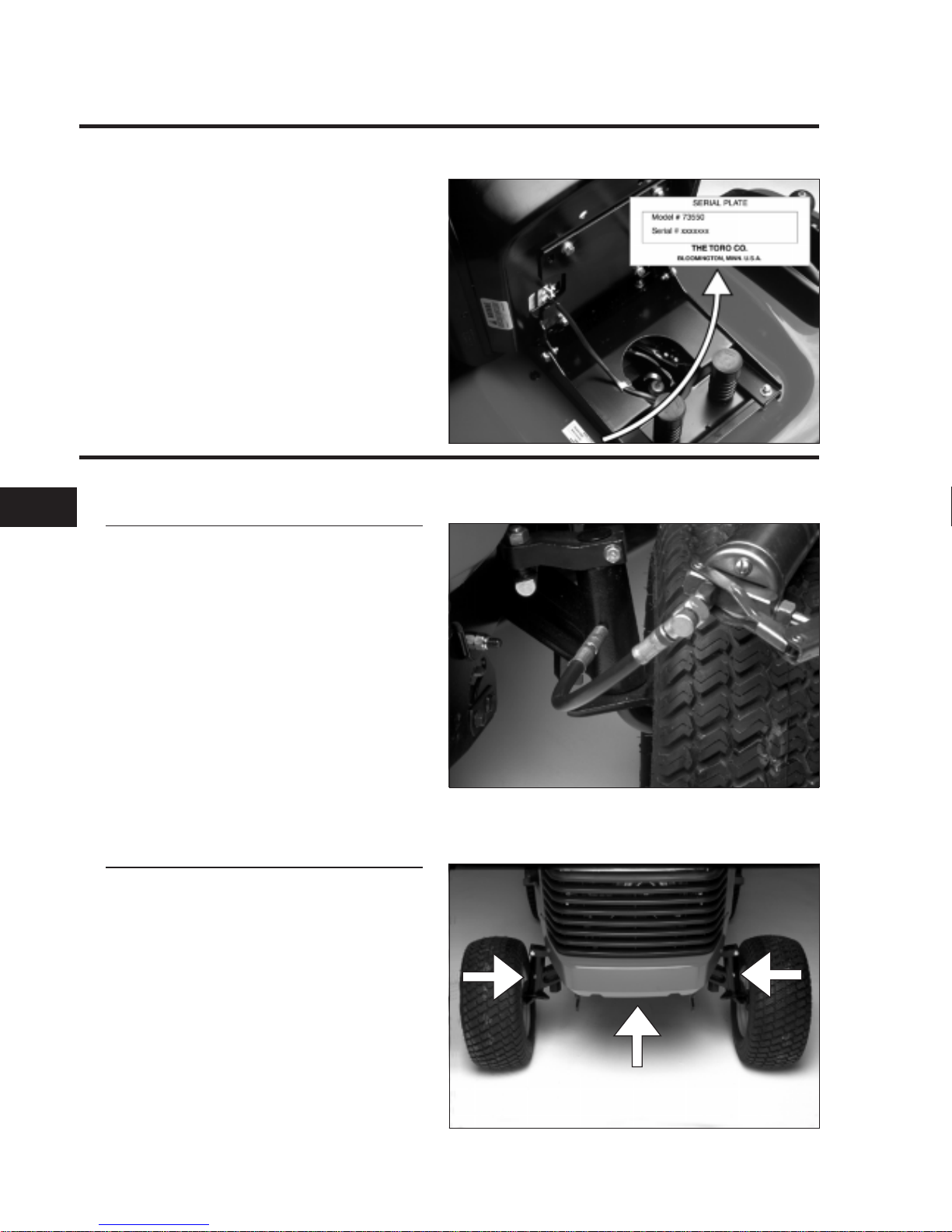
MODEL/SERIAL NUMBER LOCATION
The tractor model and serial number plate
location is shown in the illustration.
The engine has its own model and serial
number identification. Consult the appropriate
engine manufacturer’s service literature for the
location and translation of the engine model
and serial number information.
GREASING AND LUBRICATION
Service Interval/Specification
The machine should be greased every 50 hours
or yearly, whichever occurs first. You should
grease more frequently when operating
conditions are extremely dusty or sandy. See
the maintenance table in section 1c.
Grease Type: General-purpose lithium base
grease
Lubrication Points
There are 3 grease zerks on the front axle; one
on at each spindle and one at the center pivot.
2.0757.015
2.0109.043
2.0109.033
22
CHASSIS
2-4 5xi Series Tractor Service Manual
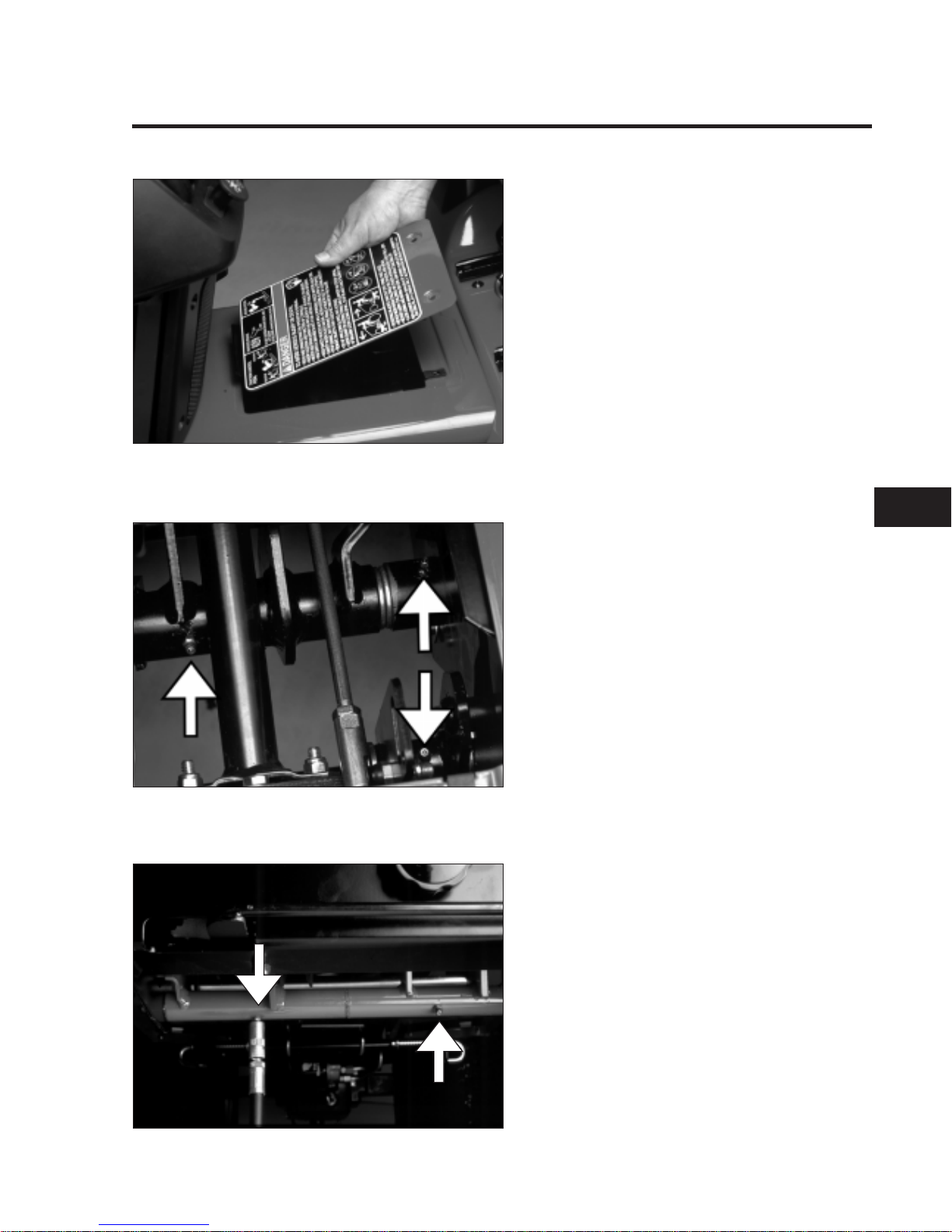
Remove the maintenance panel located in the
tunnel in front of the seat.
This will allow access to the 3 zerk fittings below.
The pulley box for the mower deck contains 2
zerk fittings; one at each pulley pivot.
2.0109.026
2.0144.023
2.0109.024
2
CHASSIS
5xi Series Tractor Service Manual 2-5
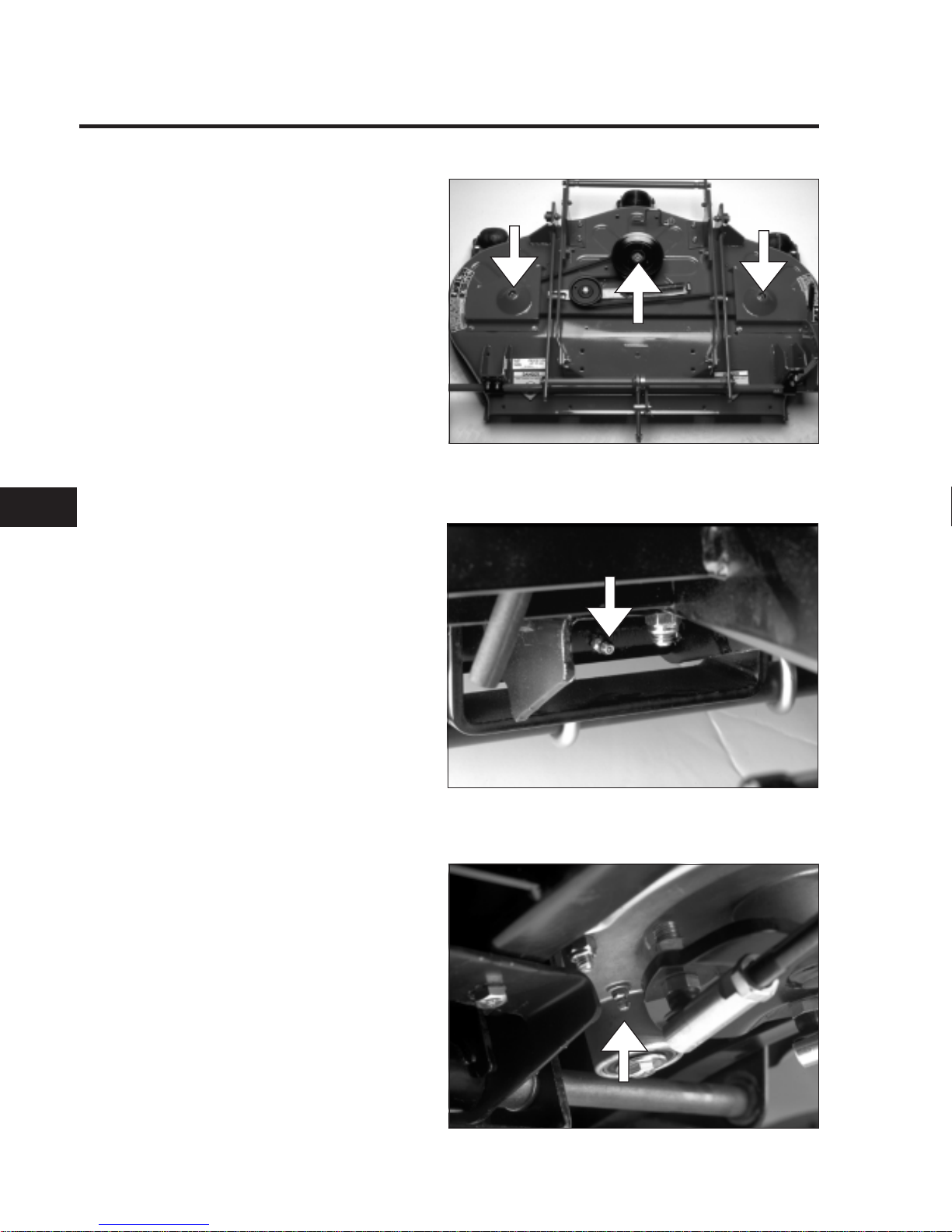
GREASING AND LUBRICATION (cont’d)
There are 3 zerk fittings located on the mower
deck spindles. Apply grease until resistance is
felt from the grease gun handle (2-3 pumps).
Also lubricate the mower deck idler arm on
decks so equipped.
The 60" deck has zerk fittings on the gage
wheels, grease every 25 hours of operation.
There is 1 zerk fitting located on the foot pedal
shaft which requires greasing.
Models with manual steering have a lubrication
point on the steering gear. Do not force
excessive amounts of grease into this fitting
(one pump of the grease gun handle only).
2.0144.069
2.0415.012
2.0415.001
22
CHASSIS
2-6 5xi Series Tractor Service Manual
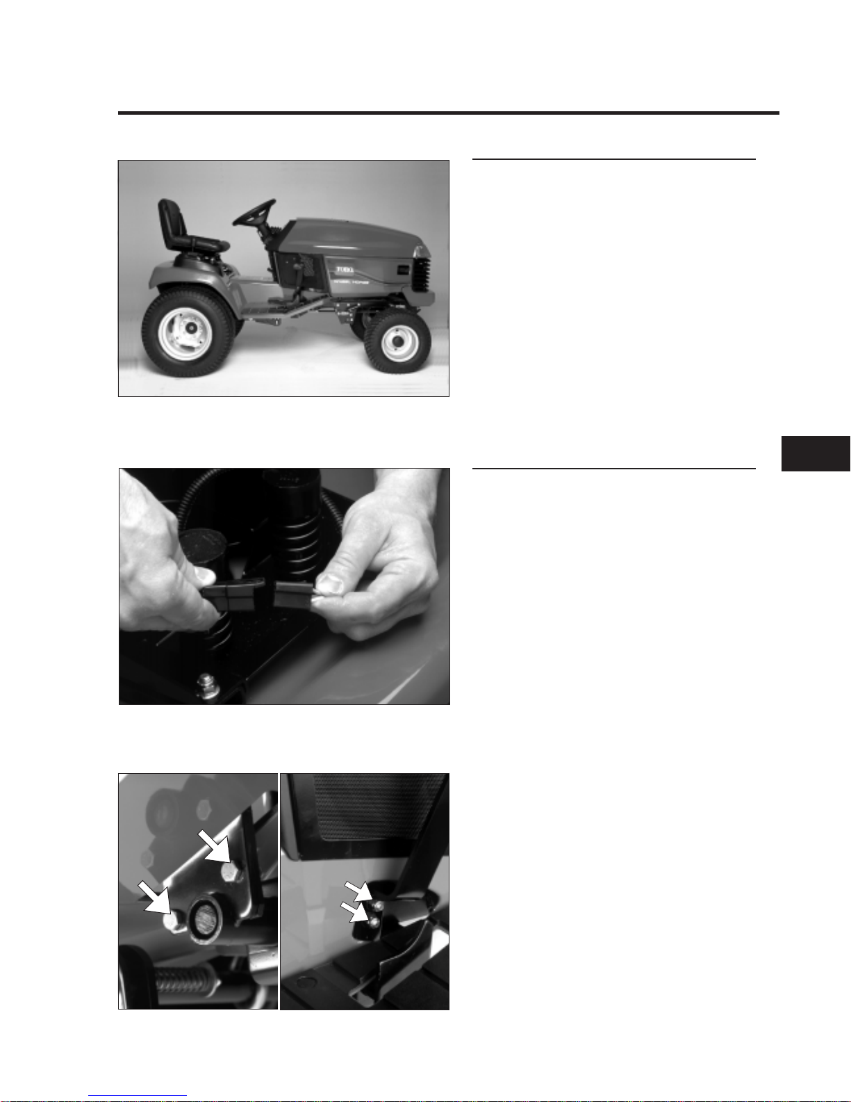
REAR FENDERS, FOOTRESTS, & TUNNEL
General Information
The seat, rear fenders, footrests, and tunnel can
be removed as a unit providing easy access to
chassis components.
Removal
1. Disconnect the electrical connections for the
seat switch, cruise control, and taillights (as
applicable) from the wiring harness.
NOTE: The cruise control and taillights
share the same connector, which is located
under the right fender.
2. Remove the brake and motion control
pedals.
2.0109.039
2.0109.003
2.0109.021
2.0109.020
2
CHASSIS
5xi Series Tractor Service Manual 2-7
REAR FENDERS, FOOTRESTS, & TUNNEL (cont’d)
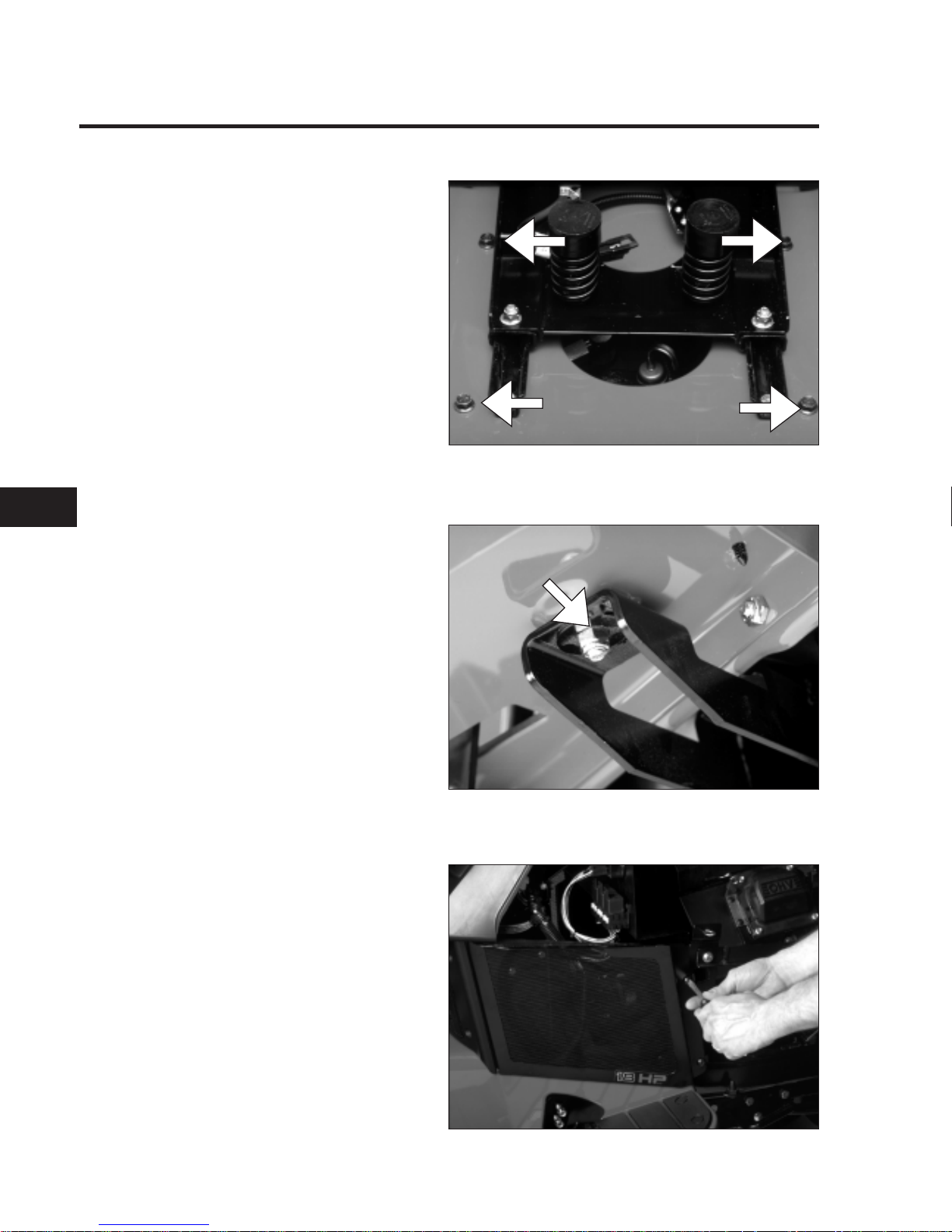
3. Remove the four bolts securing the fenders
to the frame (two on each side of the seat).
4. Remove the nuts from the front footrest
supports and the clamps from the rear
supports.
5. Remove the three air intake screens.
2.0109.015
2.0109.019
2.0109.004
22
CHASSIS
2-8 5xi Series Tractor Service Manual
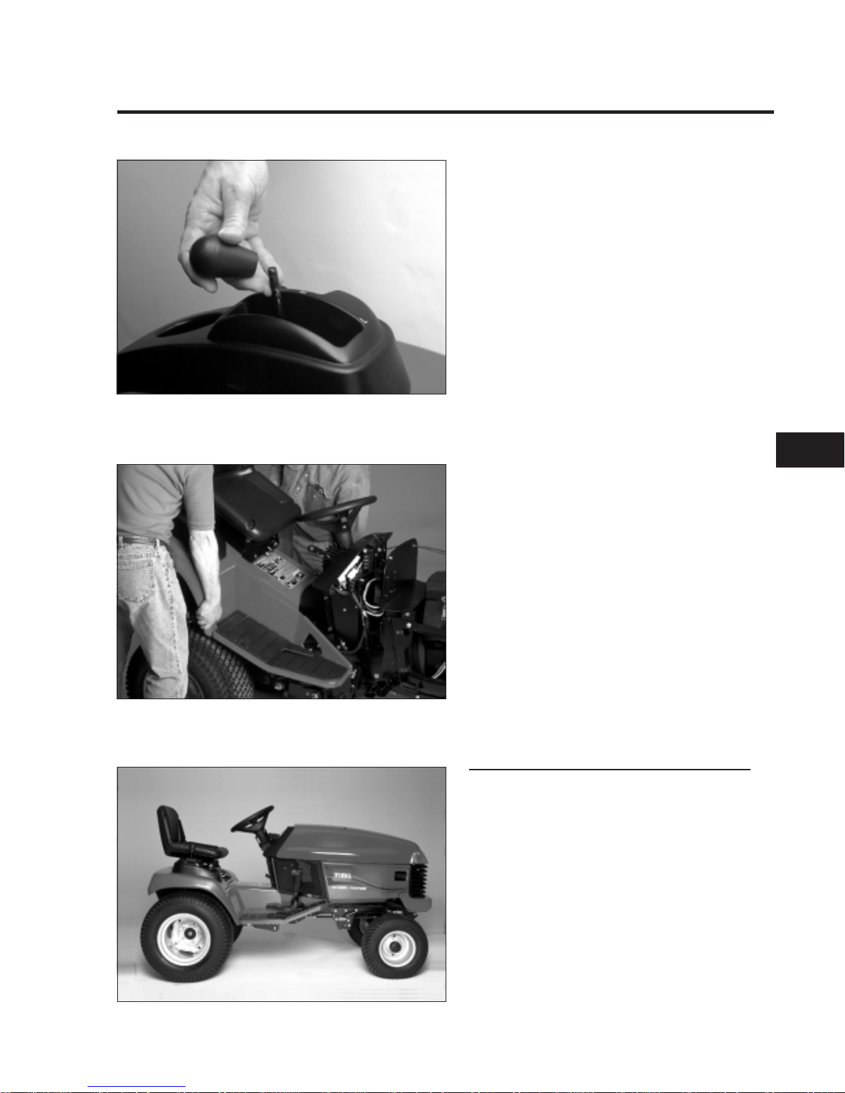
6. Remove the knob for the transaxle range
selector.
7. With the help of an assistant, lift the rear of
the fender assembly until it clears the
transaxle shift lever. Then remove the
assembly to the rear of the tractor.
Reassembly
Reverse steps 1-7 to reassemble the seat, rear
fenders, footrests, and tunnel.
NOTE: Failure to keep all hoses in place on the
top of the fuel tank could result in improper
operation of the fuel vent or supply system.
NOTE: Do not pinch any wiring between the
fender assembly and the top edges of the frame.
2.0109.017
2.0109.039
2.0109.014
2
CHASSIS
5xi Series Tractor Service Manual 2-9
FRONT WHEEL TOE-IN
Specification/Service Interval
If there is uneven tire wear, lawn scuffing, or
hard steering, toe-in may need to be adjusted.
Toe-in should be 1/8" - 1/4" (3 to 6 mm) on the
front wheels. This should be checked every
100 hours or once a year, whichever occurs first.
Measurement
1. Disengage the PTO, set the parking brake,
and turn the ignition key to OFF to stop the
engine. Remove the key.
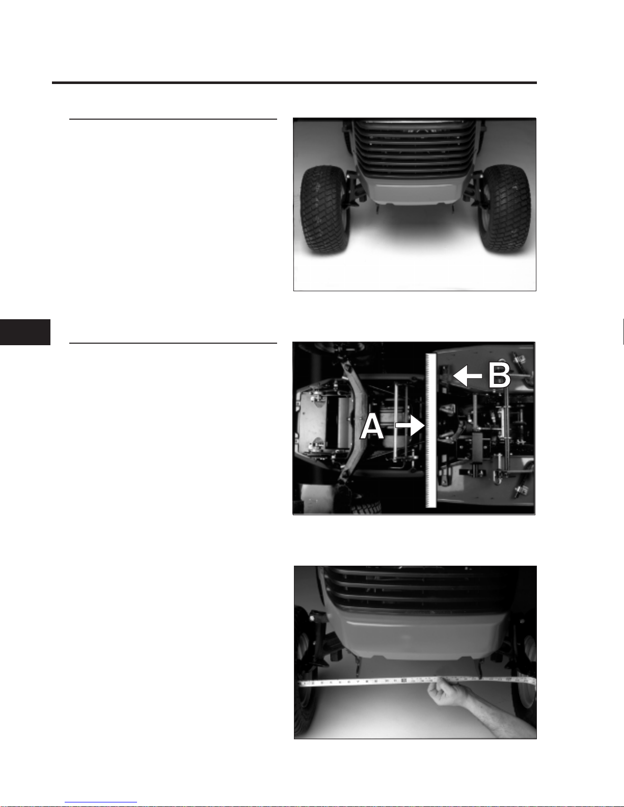
2. Turn wheels straight ahead. Square the
lower steering plate to the center line of the
frame rails by aligning a straight edge (A)
with the footrest support (B) as shown.
3. Push the front of the tires out to remove
normal looseness in the linkage.
4. Measure the distance between both front
tires at spindle level (at the front and rear of
the wheels).
5. The front measurement should be 1/8" to
1/4" (3 to 6 mm) less than the rear
measurement.
If adjustment is needed, follow the steps
outlined on the next page.
Note: The black steering tie rod end goes to the
front and has right hand threads.
2.0109.043
2.0109.035
2.0144.050
22
CHASSIS
2-10 5xi Series Tractor Service Manual

Adjustment
1. Loosen the jam nuts at the ends of the
steering rods.
2. Rotate both steering rods equal amounts to
adjust the toe-in to 1/8" to 1/4" (3 to 6 mm) .
3. Recheck the toe-in as described earlier.
IMPORTANT: Make sure that the flat surface
on the top of the front tie rod ends are
parallel to the bottom of the steering arms
(inset).
Spindle Alignment
When installing the spindle to the steering arm,
you must align the wheel so that it is parallel to
the steering arm as shown.
2.0109.047
2.0109.046
2.0109.048
2
CHASSIS
5xi Series Tractor Service Manual 2-11
STEERING WHEEL
Remove Steering Wheel
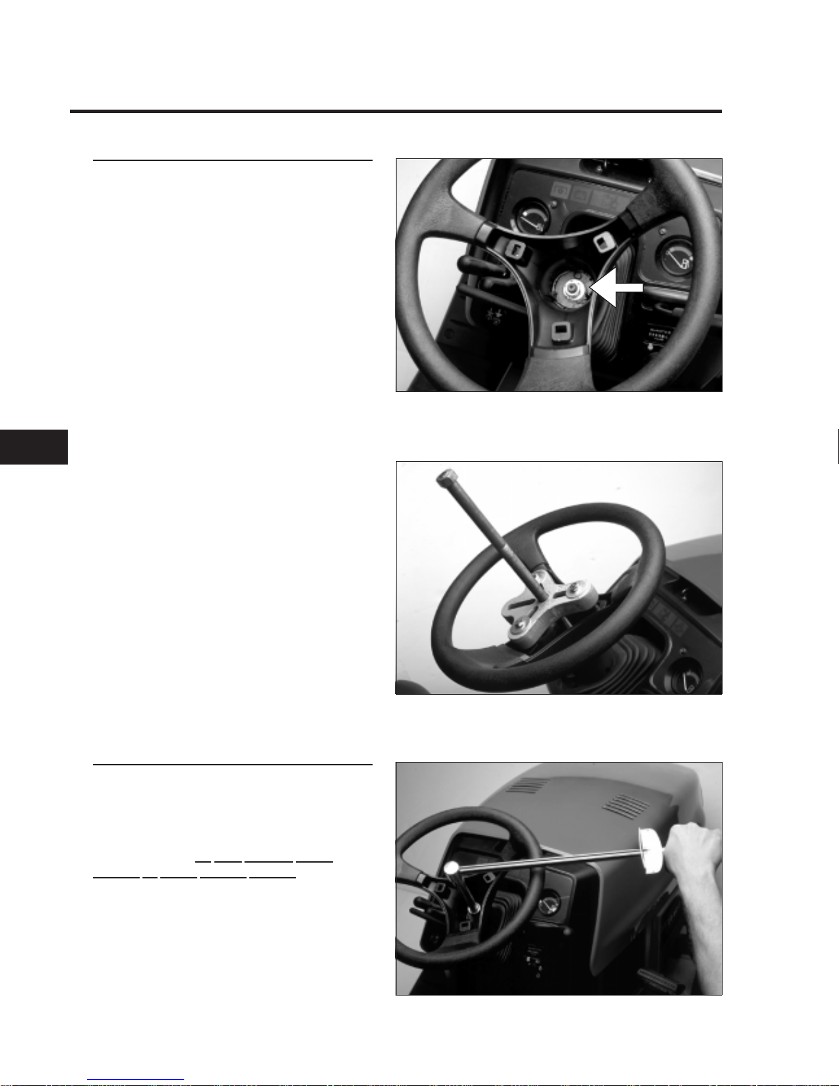
1. Remove plastic trim cover.
2. Loosen the nut securing the wheel.
3. Install puller as shown. Tighten forcing
screw to remove steering wheel.
NOTE: Install large flat washers on puller
bolts to protect steering wheel.
Reassembly
1. Place the steering wheel on the shaft,
carefully aligning the splines.
NOTE: On manual steering models, be sure to
align steering wheel in the “straight ahead”
position. There is
no fixed “straight ahead”
position on power steering models.
2. Torque the retaining nut to 45 - 50 ft·lbs.
3. Replace the trim cover.
2.0144.051
2.0144.052
2.0144.053
22
CHASSIS
2-12 5xi Series Tractor Service Manual
POWER STEERING
General Information
The 22 HP, 20 HP liquid-cooled and 23 HP
diesel tractors are equipped with power
steering.
This system routes pressurized hydraulic fluid
supplied by the hydrostatic transmission to a
directional valve located at the base of the
steering column. When the steering wheel is
turned, this valve directs pressure to a double
acting hydraulic cylinder, causing the steering
plate to pivot as the cylinder extends or
contracts. Tie rods attached to the steering
plate turn the front spindles.
When the tractor is not running, some oil will
drain from the power steering system. When
this happens, it will be necessary to purge the
air from the system. This is done by turning the
steering wheel with the engine running until the
wheels turn fully and smoothly in both
directions.
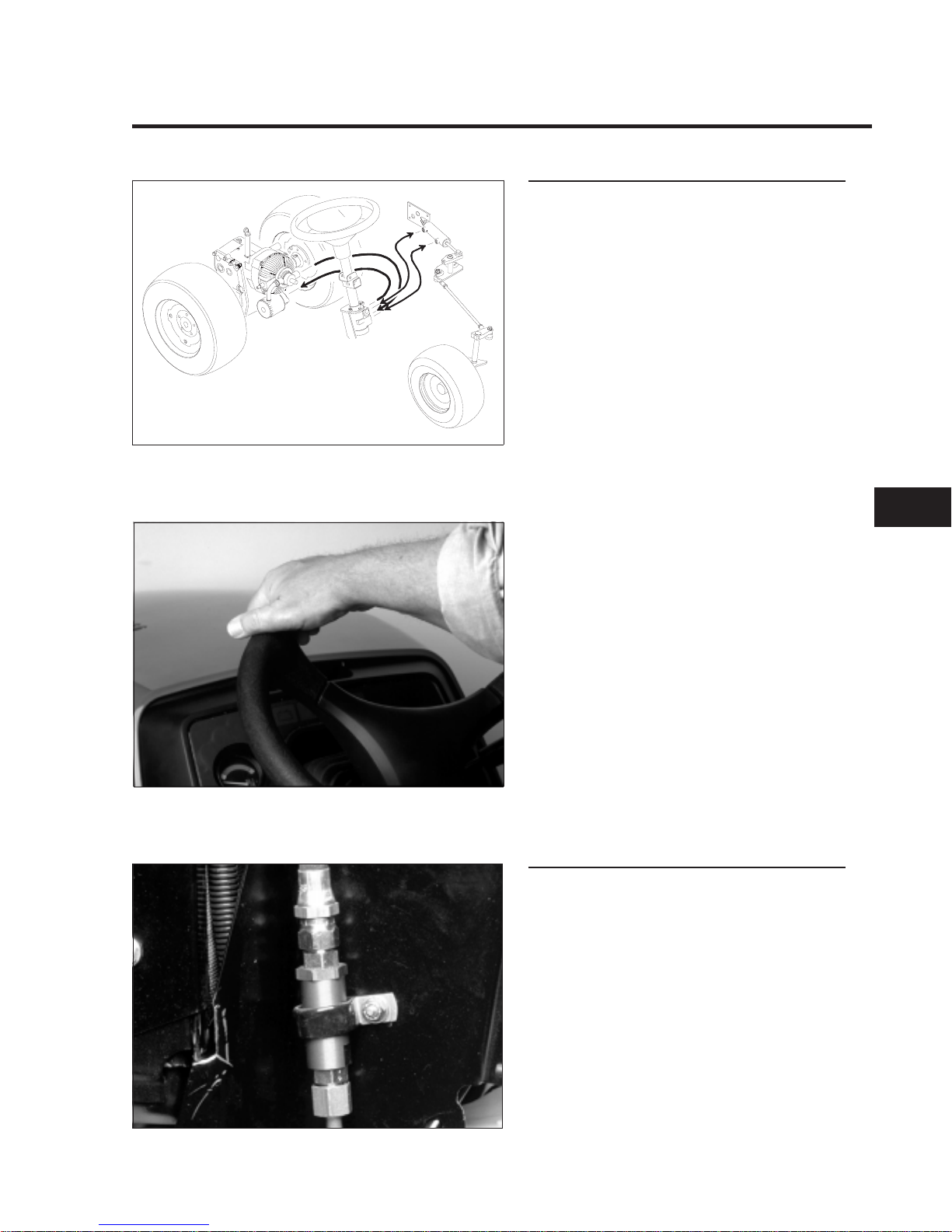
Maintenance
The power steering system is equipped with an
in-line filter screen. It should be cleaned after
initial 50 hours, then every 200 hours, or if the
power steering gets noisy.
To clean the power steering screen:
1. Remove the left and center air intake
screens.
2. Remove the screen housing from the clamp
securing it to the left-hand side of steering
tower.
.3. Remove the top hose first to prevent oil from
back-flushing the screen.
4. Remove the hydraulic lines, and seal the
ends to keep out dirt.
3.7195.029
2.0144.16
2.0109.044
2
CHASSIS
5xi Series Tractor Service Manual 2-13
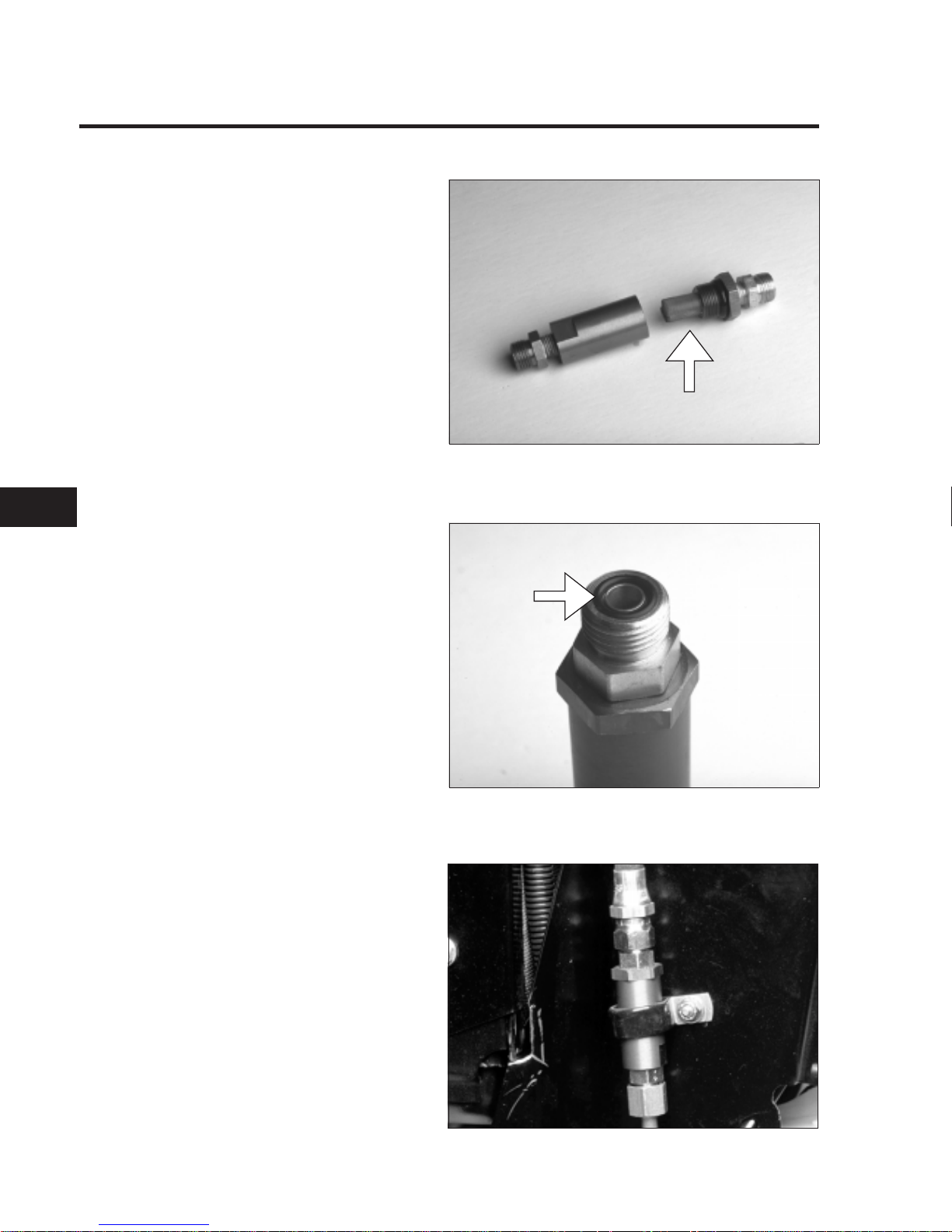
POWER STEERING (cont’d)
3. Disassemble the housing, and clean the
screen with solvent.
4. Inspect the “O” rings that seal the lines and
housing. Replace them if there are any
signs of cuts or deterioration, (i.e. hardening
or swelling of the rubber).
Lubricate the “O” rings before reassembly.
5. Reassemble the housing, replace the lines,
and secure to steering tower.
6. Bleed air from the system by turning the
steering wheel from stop to stop several
times.
7. Check the hydrostatic transmission
fluid level.
2.0144.076
2.0144.16
2.0144.086
22
CHASSIS
2-14 5xi Series Tractor Service Manual
SMART TURN™ STEERING
General Information
The Smart Turn Steering™ feature automatically
lowers the speed of the tractor in tight turns.
The decrease in speed is directly proportional
to the sharpness of the turn, up to a maximum
speed reduction of approximately 40% .
The Smart Turn Steering feature permits sharp
turns to be made without always having to
change speed control position. The original
speed is restored as the turn is completed.
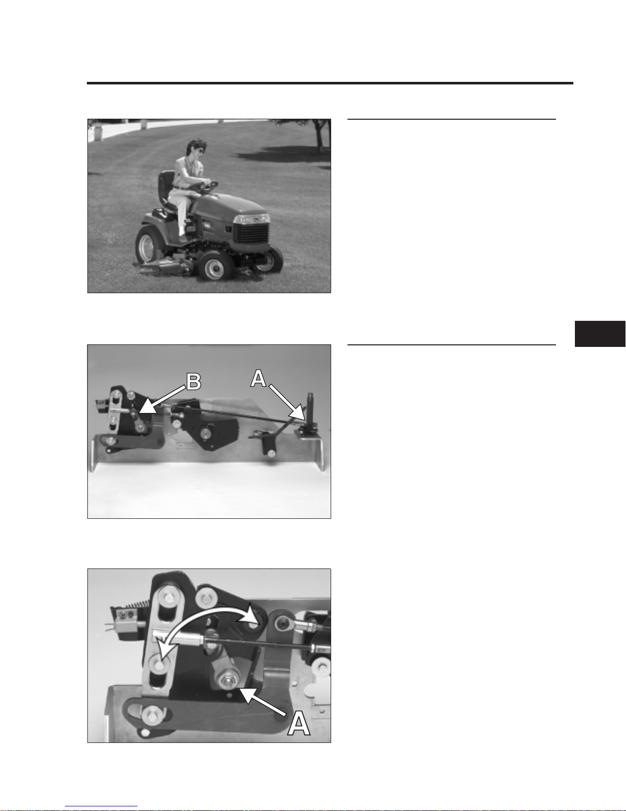
Theory of Operation
The steering plate (A) is attached to the speed
control lever (B) on the hydrostatic transmission
through a system of linkage and levers.
When the steering wheel is turned, the linkage
pushes the speed control lever (A) on the
hydrostatic transmission towards the neutral
position and slows the tractor.
2.3653.005
2.0144.63
2.0144.059
2
CHASSIS
5xi Series Tractor Service Manual 2-15
SMART TURN™ STEERING (cont’d)
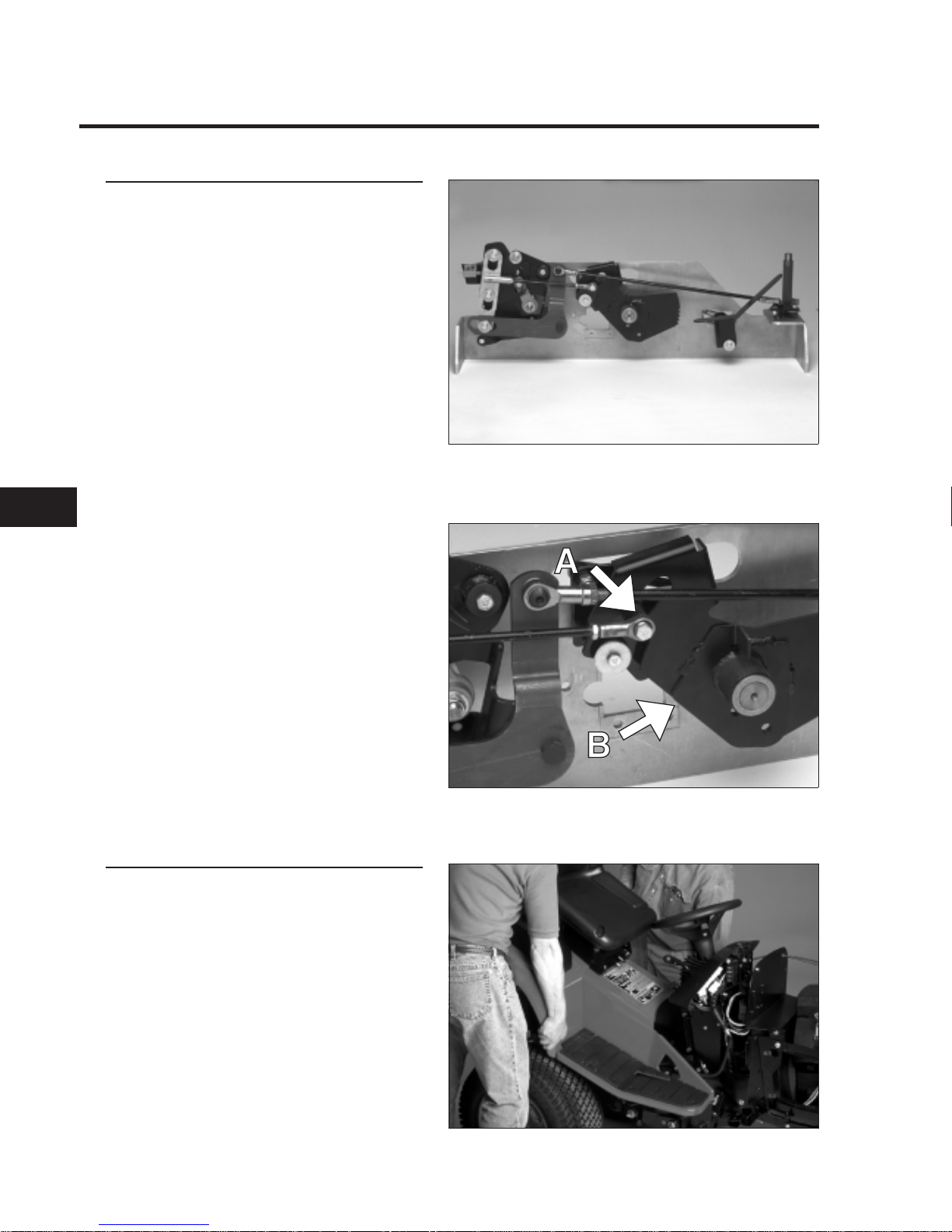
Inspection
The Smart Turn Steering system was set-up at
the factory and should not need any
adjustment. Adjustment must be verified if the
transaxle is removed and reinstalled.
Correct adjustment can be verified by checking
the position of the bushing (A) in the slot of the
brake pivot plate (B). The bushing should not
contact either side of the slot.
Correct adjustment can be verified by removing
the maintenance panel and visually checking
the position of bushing (A). It should be
centered in the slot in the brake pivot (B). The
bushing should not contact either side of the
slot when the brake is applied.
Adjustments
IMPORTANT: The adjustment procedure must
be performed in the sequence given.
If adjustment of the system is necessary:
1. Remove the rear fenders and tunnel from the
tractor as outlined on page 2-7.
NOTE: It is important that the toe-in is properly
adjusted before adjusting the Smart Turn
Steering linkage. Verify setting by following the
procedure starting on page 2-10.
2.0144.059
2.0109.014
2.0144.066
22
CHASSIS
2-16 5xi Series Tractor Service Manual
 Loading...