

Page 1
Part No. 15212SL
Service Manual
Preface
The purpose of this publication is to provide the service
technician with information for troubleshooting, testing
and repair of major systems and components on the
Reelmaster 5010- H (Hybrid).
REFER TO THE TRACTION UNIT AND CUTTING
UNIT OPERATOR’S MANUALS FOR OPERATING,
MAINTENANCE AND ADJUSTMENT INSTRUCTIONS. Space is provided in Chapter 2 of this book to
insert the Operator’s Manuals and Parts Catalogs for
your machine. Additional copies of the Operator’s
Manual and Parts Catalog are available on the internet
at www.Toro.com.
The Toro Company reserves the right to change product
specifications or this publication without notice.
Reelmaster
This safety symbol means DANGER, WARNING,
or CAUTION, PERSONAL SAFETY INSTRUCTION. When you see this symbol, carefully read
the instructions that follow. Failure to obey the
instructions may result in personal injury.
NOTE: A NOTE will give general information about the
correct operation, maintenance, service, testing or repair of the machine.
IMPORTANT: The IMPORTANT notice will give important instructions which must be followed to prevent damage to systems or components on the
machine.
R
5010- H
E The Toro Company - 2015
Page 2

This page is intentionally blank.
Reelmaster 5010- H
Page 3

Table Of Contents
Chapter 1 - Safety
Safety Instructions 1 - 2..........................
Jacking Instructions 1 - 5.........................
Safety and Instruction Decals 1 - 6................
Chapter 2 - Product Records and Maintenance
Product Records 2 - 1...........................
Maintenance 2 - 1...............................
Equivalents and Conversions 2 - 2................
Torque Specifications 2 - 3.......................
Chapter 3 - Kubota Diesel Engine
Specifications 3 - 2..............................
General Information 3 - 3........................
Service and Repairs 3 - 4........................
KUBOTA WORKSHOP MANUAL, DIESEL ENGINE,
05- E4B SERIES
Chapter 4 - Hydraulic System
Specifications 4 - 2..............................
General Information 4 - 3........................
Hydraulic Schematic 4 - 10.......................
Hydraulic Flow Diagrams 4 - 12...................
Special Tools 4 - 20.............................
Troubleshooting 4 - 25...........................
Testing 4 - 30...................................
Service and Repairs 4 - 52.......................
SAUER- DANFOSS LPV CLOSED CIRCUIT AXIAL
PISTON PUMPS REPAIR MANUAL
SAUER- DANFOSS LPV CLOSED CIRCUIT AXIAL
PISTON PUMPS SERVICE INSTRUCTIONS
EATON DELTA MOTORS PARTS AND REPAIR
MANUAL
PARKER TORQMOTOR
(TC, TB, TE, TJ, TF, TG, TH AND TL SERIES)
SAUER- DANFOSS STEERING UNIT TYPE OSPM
SERVICE MANUAL
TM
SERVICE PROCEDURE
Chapter 5 - Electrical System
General Information 5 - 2........................
Electrical System Operation 5 - 4.................
Special Tools 5 - 6..............................
InfoCenter Display 5 - 10.........................
Troubleshooting 5 - 18...........................
Electrical System Quick Checks 5 - 40.............
Adjustments 5 - 42..............................
Component Testing 5 - 46........................
Service and Repairs 5 - 77.......................
Chapter 6 - Chassis
Specifications 6 - 2..............................
General Information 6 - 2........................
Special Tools 6 - 3..............................
Service and Repairs 6 - 4........................
Chapter 7 - Cutting Units
Specifications 7 - 2..............................
General Information 7 - 3........................
Special Tools 7 - 4..............................
Factors That Can Affect Cutting Performance 7 - 8..
Set- Up and Adjustments 7 - 12...................
Service and Repairs 7 - 14.......................
SafetyProduct Records
and Maintenance
Engine
Kubota Diesel
System
Hydraulic
System
Chassis
Reelmaster 5010- H
Cutting Electrical
Units
Page 4

This page is intentionally blank.
Reelmaster 5010- H
Page 5

Table Of Contents (Continued)
Chapter 8 - Groomer
General Information 8 - 2........................
Special Tools 8 - 3..............................
Grooming Performance 8 - 4.....................
Troubleshooting 8 - 5............................
Adjustments 8 - 7...............................
Service and Repairs 8 - 8........................
Chapter 9 - Foldout Drawings
Electrical Drawing Designations 9 - 2..............
Hydraulic Schematic 9 - 3........................
Electrical Schematic 9 - 4........................
Wire Harness Drawings 9 - 6.....................
GroomerFoldout
Drawings
Reelmaster 5010- H
Page 6

This page is intentionally blank.
Reelmaster 5010- H
Page 7

Table of Contents
SAFETY INSTRUCTIONS 2......................
Before Operating 2............................
While Operating 3.............................
Maintenance and Service 4....................
JACKING INSTRUCTIONS 5.....................
SAFETY AND INSTRUCTION DECALS 6..........
Chapter 1
Safety
Safety
Reelmaster 5010- H Page 1 - 1 Safety
Page 8

Safety Instructions
Reelmaster machines meet or exceed safety standard
specifications when weights are installed according to
information in the Traction Unit Operator’s Manual. Although hazard control and accident prevention are partially dependent upon the design and configuration of
the machine, these factors are also dependent uponthe
awareness, concern and proper training of the personnel involved in the operation, transport, maintenance
and storage of the machine. Improper use or maintenance of the machine can result in injury or death. To reduce the potential for injury or death, comply with the
following safety instructions.
Before Operating
WARNING
To reduce the potential for injury or death, comply with the following safety instructions.
1. Review and understand the contents of the Operator’ s Manuals and Operator Training DVD before starting and operating the machine. Become familiar withthe
controls and know how to stop the machine and engine
quickly. Additional copies of the Operator’s Manual are
available on the internet at www.Toro.com.
2. Keep all shields, safety devices and decals in place.
If a shield, safety device or decal is defective, illegible
or damaged, repair or replace it before operating the
machine. Also tighten any loose nuts, bolts or screws to
ensure machine is in safe operating condition.
3. Assure interlock switches are adjusted correctly so
engine cannot be started unless traction pedal is in
NEUTRAL and Enable/Disable switch is OFF (disabled).
4. Since fuel is flammable, handle it carefully:
A. Store fuel in containers specifically designed for
this purpose.
B. Do not remove machine fuel tank cap while engine is hot or running.
C. Do not smoke while handling fuel.
D. Fill fuel tank outdoors and only to within an inch of
the top of the tank, not the filler neck. Do not overfill.
E. Replace fueltank and fuel container caps securely after refueling machine.
F. If fuel is spilled, do not attempt to start the engine
but move the machine away from the area of spillage. Avoid creating any source of ignition until fuel
vapors have dissipated. Wipe up any spilled fuel.
Reelmaster 5010- HPage 1 - 2Safety
Page 9

While Operating
1. Sit on the seat when starting and operating the machine.
2. Before starting the engine:
A. Apply the parking brake.
B. Make sure the traction pedal is in NEUTRAL, the
Enable/Disable switch is in the disabled position and
the engine speed switch is in the mid- speed position.
C. Turn the ignition switch to the ON/PREHEAT position to energize the glow plugs. After allowing the
glow plugs to preheat, turn the switch to the START
position. Release the switch to the ON/PREHEAT
position when the engine starts.
D. After engine is started, release parking brake and
keep foot off traction pedal. Machine must not move.
If movement is evident, the traction pedal linkage is
adjusted incorrectly; therefore, shut engine off and
adjust traction pedal linkage until machine does not
move when traction pedal is released (see T raction
Unit Operator’s Manual).
3. Do not run engine in a confined area without adequate ventilation. Exhaust fumes are hazardous and
could possibly be deadly.
4. Do not touch engine, radiator, exhaust system or hydraulic components while engine is running or soonafter
it is stopped. These areas could be hot enough to cause
burns.
5. Before getting off the seat:
A. Ensure that traction pedal is in NEUTRAL.
B. Lower and disengage cutting units. Wait for all
movement to stop.
C. Apply parking brake.
D. Move the engine speed switch to the low idle position and allow the engine to reach low idle speed.
E. Stop engine and remove key from ignition switch.
6. Anytime the machine is parked (short or long term),
the cutting units should be lowered to the ground. This
relieves pressure from the hydraulic lift circuit and eliminates the risk of the cutting units unexpectedly lowering
to the ground.
7. Do not park on slopes unless wheels are chocked or
blocked.
Safety
Reelmaster 5010- H Page 1 - 3 Safety
Page 10

Maintenance and Service
1. Before servicing or making adjustments, lower cutting units, apply parking brake, stop engine and remove
key from the ignition switch.
2. Make sure machine is in safe operating condition by
keeping all nuts, bolts and screws tight.
3. Never store the machine or fuel container inside
where there is an open flame, such as near a water heater or furnace.
4. Make sure all hydraulic line connectors are tight, and
all hydraulic hoses and lines are in good condition before applying pressure to the hydraulic system.
5. Keep body and hands away from pin hole leaks in hydraulic lines that eject high pressure hydraulic fluid. Use
cardboard or paper to find hydraulic leaks. Hydraulic
fluid escaping under pressure can penetrate skin and
cause injury. Fluid accidentally injected into the skin
must be surgically removed within a few hours by a doctor familiar with this form of injury or gangrene may result.
6. Before disconnecting or performing any work on the
hydraulic system, all pressure in the system must be relieved by using all of the hydraulic controls with the engine not running (see Relieving Hydraulic Pressure in
the General Information section of Chapter 4 - Hydraulic System).
7. Use care when checking or servicing the cutting
units. Wear appropriate gloves and use caution when
servicing them.
8. T o reduce potential fire hazard, keep engine area
free of excessive grease, grass, leaves and dirt. Clean
protective screen on machine frequently.
13.Before installing, removing or working on 48 VDC
system components (e.g. cutting units, motor/generator), separatesystem components from the 48 VDC battery pack by unplugging the 48 VDC battery disconnect
(see 48 VDC Battery Disconnect in the General Information section of Chapter 5 - Electrical System). Plug
the connector back in before operating the machine.
14.Battery acid is poisonous and can cause burns.
Avoid contact with skin, eyes and clothing. Protect your
face, eyes and clothing when working with a battery.
15.Battery gases can explode. Keep cigarettes, sparks
and flames away from the battery.
16.When changing tires, attachments or performing
other service, use correct jacks, hoists and supports.
Make sure machine is parked on a solid level floor such
as a concrete floor. Prior to raising the machine, remove
any attachments that may interfere with the safe and
proper raising of the machine. Always chock or block
wheels. Use jack stands or appropriate load holding devices to support the raised machine. If the machine is
not properly supported, the machine may move or fall,
which may result in personal injury (see Jacking Instructions in this section).
17.If major repairs are ever needed or assistance is desired, contact an Authorized Toro Distributor.
18.When welding on machine, disconnect battery
cables to prevent damage to machine electronic equipment. Disconnect negative battery cable first and positive cable last. Also, disconnect wire harness connector
from the TEC controller and disconnect the terminal
connector from the alternator. Attach welder ground
cable no more than two (2) feet (0.6 meters) from the
welding location.
9. If engine must be running to perform maintenance or
to make an adjustment, keep hands, feet, clothing and
other parts of the body away from the cutting units and
other moving parts. Keep bystanders away.
10.To assure safety and accuracy, check maximum engine speed.
1 1.Shut engine off before checking or adding oil to the
engine crankcase.
12.Disconnect 12 VDC battery located at the rear of the
machine before servicing themachine. Disconnect negative battery cable first and positive cable last. If battery
voltage is required for troubleshooting or test procedures, temporarily connect the battery. Reconnect positive battery cable first and negative cable last.
19.Make sure to dispose of potentially harmful waste
(e.g. fuel, oil, engine coolant, filters, batteries) in an environmentally safe manner. Follow all local codes and
regulations when recycling or disposing of waste.
20.At the time of manufacture, the machine conformed
to the safety standards for riding mowers. To assure optimum performance and continued safety certification of
the machine, use genuine Toro replacement parts and
accessories. Replacement parts and accessories made
by other manufacturers may result in non-conformance
with the safety standards, and the warranty may be
voided.
Reelmaster 5010- HPage 1 - 4Safety
Page 11
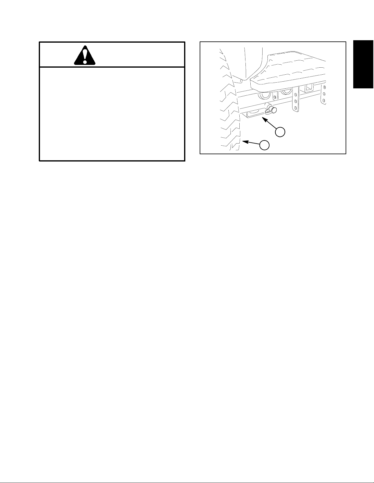
Jacking Instructions
CAUTION
When changing tires, attachments or performing other service, use correct hoists, jacks and
jack stands. Make sure machine is parked on a
solid, level surface such as a concrete floor.
Prior to raising machine, remove any attachmentsthat may interfere with the safeand proper raising of the machine. Always chock or
block wheels. Use jack stands or other appropriate load holding devices to support the
raised machine. If the machine is not properly
supported, the machine may move or fall,
which may result in personal injury.
Front End Jacking (Fig. 1)
1. Apply parking brake and chock both rear tires to prevent the machine from moving.
2. Position jack securely below the rectangular pad under the frame axle tube, just to the inside of the front
wheel.
3. Jack front of machine off the ground.
4. Position jack stands under the frame as close to the
raised wheel as possible to support the machine.
Safety
2
1
Figure 1
1. Front wheel 2. Front jacking point
Rear End Jacking
1. Apply parking brake and chock both front tires to prevent the machine from moving.
2. Place jack securely at the center of the rear axle under the axle pivot bracket. Jack rear of machine off the
ground.
3. T o support the raised machine, position jack stands
under the frame rail next to the axle support bracket.
Reelmaster 5010- H Page 1 - 5 Safety
Page 12

Safety and Instruction Decals
Numerous safety and instruction decals are affixed to
the traction unit and the cutting units of yourReelmaster.
If any decal becomes illegible or damaged, install a new
decal. Part numbers for decals are listed in your Part
Catalogs. Order replacement decals from your Authorized Toro Distributor.
Reelmaster 5010- HPage 1 - 6Safety
Page 13

Product Records and Maintenance
Table of Contents
PRODUCT RECORDS 1.........................
MAINTENANCE 1..............................
EQUIVALENTS AND CONVERSIONS 2...........
Decimal and Millimeter Equivalents 2............
U.S. to Metric Conversions 2...................
TORQUE SPECIFICATIONS 3...................
Fastener Identification 3.......................
Using a Torque Wrench with an Offset Wrench 3..
Standard Torque for Dry, Zinc Plated and
Steel Fasteners (Inch Series) 4...............
Standard Torque for Dry, Zinc Plated and
Steel Fasteners (Metric Series) 5..............
Other Torque Specifications 6..................
Conversion Factors 6.........................
Chapter 2
Product Records
and Maintenance
Product Records
Insert Operator’s Manual and Parts Catalog for your
Reelmaster at the end of this chapter. Refer to Operator’s Manual for recommended maintenance intervals.
Additionally, insert Installation Instructions, Operator’s
Manuals and Parts Catalogs for any accessories that
have been installed on your Reelmaster at the end of
this section.
Maintenance
Maintenance procedures and recommended service intervals for your Reelmaster are covered in the Operator’s Manual. Refer to that publication when performing
regular equipment maintenance. Several maintenance
procedures have break- in intervals identified in the Operator’s Manual. Refer to the Engine Operator’s Manual
for additional engine specific maintenance procedures.
Reelmaster 5010- H Page 2 - 1 Product Records and Maintenance
Page 14

Equivalents and Conversions
0.09375
Reelmaster 5010- HPage 2 - 2Product Records and Maintenance
Page 15
Torque Specifications
Recommended fastener torque values are listed in the
following tables. For critical applications, as determined
by Toro, either the recommended torque or a torque that
is unique to the application is clearly identified and specified in this Service Manual.
These Torque Specifications for the installation and
tightening of fasteners shall apply to all fasteners which
do not have a specific requirement identified in this Service Manual. The following factors shall be considered
when applying torque: cleanliness of the fastener, use
of a thread sealant (e.g. Loctite), degree of lubrication
on the fastener, presence of a prevailing torque feature
(e.g. Nylock nut), hardness of the surface underneath
the fastener’s head or similar condition which affects the
installation.
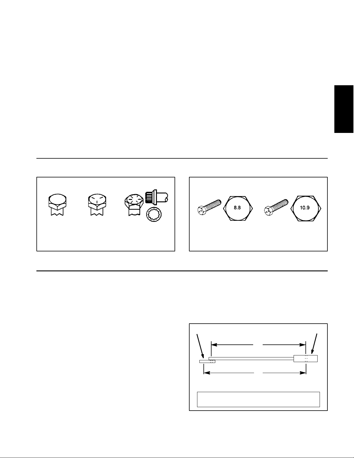
Fastener Identification
As noted in the following tables, torque values should be
reduced by 25% for lubricated fasteners to achieve
the similar stress as a dry fastener. Torque values may
also have to be reduced when the fastener is threaded
into aluminum or brass. The specific torque value
should be determined based on the aluminum or brass
material strength, fastener size, length of thread engagement, etc.
The standard method of verifying torque shall be performed by marking a line on the fastener (head or nut)
and mating part, then back off fastener 1/4 of a turn.
Measure the torque required to tighten the fastener until
the lines match up.
Product Records
and Maintenance
Grade 1 Grade 5 Grade 8
Inch Series Bolts and Screws
Figure 1
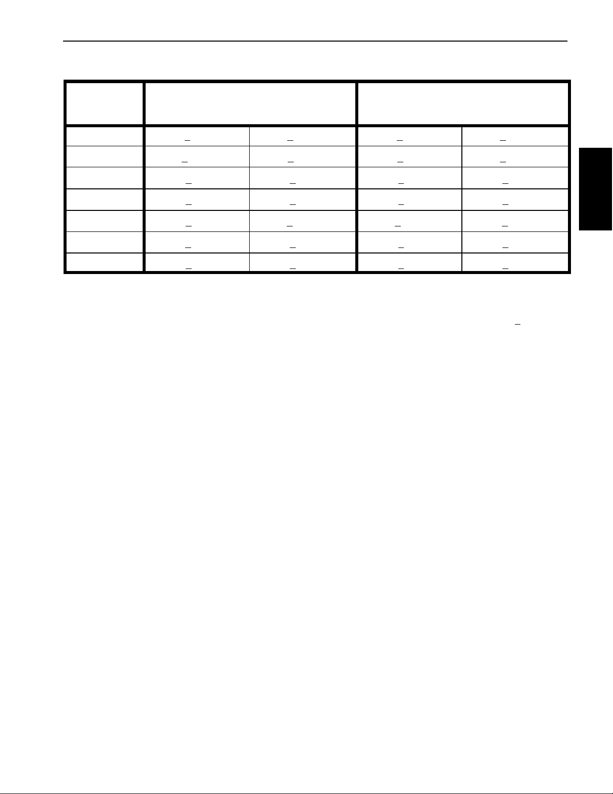
Using a Torque Wrench with an Offset Wrench
Use of an offset wrench (e.g. crowfoot wrench) will affect
torque wrench calibration due to the effective change of
torque wrench length. When using a torque wrench with
an offset wrench, multiply the listed torque recommendation by the calculated torque conversion factor (Fig.
3) to determine proper tightening torque. Tightening
torque when using a torque wrench with an offset
wrench will be lower than the listed torque recommendation.
Example: Themeasuredeffectivelengthofthetorque
wrench (distance from the center of the handle to the
center of the square drive) is 18”.
Themeasuredeffectivelengthofthetorquewrenchwith
the offset wrench installed (distance from the center of
the handle to the center of the offset wrench) is 19”.
Class 8.8 Class 10.9
Metric Bolts and Screws
Figure 2
If the listed torque recommendation for a fastener is
from 76 to 94 ft- lb, the proper torque when using this
torque wrench with an offset wrench would be from 72
to 89 ft- lb.
(effective length of
torque wrench)
A
B
(effective length of torque
wrench + offset wrench)
TORQUE CONVERSION FACTOR = A / B
T orque wrenchOffset wrench
Thecalculatedtorqueconversionfactorforthistorque
wrench with this offset wrench would be 18 / 19 = 0.947.
Reelmaster 5010- H Page 2 - 3 Product Records and Maintenance
Figure 3
Page 16

Standard Torque for Dry, Zinc Plated and Steel Fasteners (Inch Series)
Thread Size
#6- 32UNC
#6- 40UNF 17 + 2 192 + 23 25 + 3 282 + 34
#8- 32UNC
#8- 36UNF 31 + 4 350 + 45 43 + 5 486 + 56
# 10 - 24 UNC
#10- 32UNF 48 + 5 542 + 56 68 + 7 768 + 79
1/4 - 20 UNC 48 + 7 53 + 7 599 + 79 100 + 10 1130 + 113 140 + 15 1582 + 169
1/4 - 28 UNF 53 + 7 65 + 10 734 + 11 3 115 + 12 1299 + 136 160 + 17 1808 + 192
5/16 - 18 UNC 115 + 15 105 + 15 1186 + 169 200 + 25 2260 + 282 300 + 30 3390 + 339
5/16 - 24 UNF 138 + 17 128 + 17 1446 + 192 225 + 25 2542 + 282 325 + 33 3672 + 373
3/8 - 16 UNC 16 + 2 16 + 2 22 + 3 30 + 3 41 + 4 43 + 5 58 + 7
Grade 1, 5 &
8withThin
Height Nuts
in- lb in- lb N- cm in- lb N- cm in- lb N- cm
10 + 2 13 + 2 147 + 23
13 + 2 25 + 5 282 + 30
18 + 2 30 + 5 339 + 56
ft- lb ft- lb N- m ft- lb N- m ft- lb N- m
SAE Grade 1 Bolts, Screws, Studs &
Sems with Regular Height Nuts
(SAE J995 Grade 2 or Stronger Nuts)
SAE Grade 5 Bolts, Screws, Studs &
Sems with Regular Height Nuts
(SAE J995 Grade 2 or Stronger Nuts)
15 + 2 169 + 23 23 + 3 262 + 34
29 + 3 328 + 34 41 + 5 463 + 56
42 + 5 475 + 56 60 + 6 678 + 68
SAE Grade 8 Bolts, Screws, Studs &
Sems with Regular Height Nuts
(SAE J995 Grade 5 or Stronger Nuts)
3/8 - 24 UNF 17 + 2 18 + 2 24 + 3 35 + 4 47 + 5 50 + 6 68 + 8
7/16 - 14 UNC 27 + 3 27 + 3 37 + 4 50 + 5 68 + 7 70 + 7 95 + 9
7/16 - 20 UNF 29 + 3 29 + 3 39 + 4 55 + 6 75 + 8 77 + 8 104 + 11
1/2 - 13 UNC 30 + 3 48 + 7 65 + 9 75 + 8 102 + 11 105 + 11 142 + 15
1/2 - 20 UNF 32 + 4 53 + 7 72 + 9 85 + 9 115 + 12 120 + 12 163 + 16
5/8 - 11 UNC 65 + 10 88 + 12 119 + 16 150 + 15 203 + 20 210 + 21 285 + 28
5/8 - 18 UNF 75 + 10 95 + 15 129 + 20 170 + 18 230 + 24 240 + 24 325 + 33
3/4 - 10 UNC 93 + 12 140 + 20 190 + 27 265 + 27 359 + 37 375 + 38 508 + 52
3/4 - 16 UNF 115 + 15 165 + 25 224 + 34 300 + 30 407 + 41 420 + 43 569 + 58
7/8 - 9 UNC 140 + 20 225 + 25 305 + 34 430 + 45 583 + 61 600 + 60 813 + 81
7/8 - 14 UNF 155 + 25 260 + 30 353 + 41 475 + 48 644 + 65 667 + 66 904 + 89
NOTE: Reduce torque values listed in the table above
by 25% for lubricated fasteners. Lubricated fasteners
are defined as threads coated with a lubricant such as
engine oil or thread sealant such as Loctite.
NOTE: The nominal torque values listed above for
Grade 5 and 8 fasteners are based on 75% of the minimum proof load specified in SAE J429. The tolerance is
approximately +
10% of the nominal torque value. Thin
height nuts include jam nuts.
NOTE: Torque values may have to be reduced when
installing fasteners into threaded aluminum or brass.
The specific torque value should be determined based
on the fastener size, the aluminum or base material
strength, length of thread engagement, etc.
Reelmaster 5010- HPage 2 - 4Product Records and Maintenance
Page 17
Standard Torque for Dry, Zinc Plated and Steel Fasteners (Metric Series)
Class 8.8 Bolts, Screws and Studs with
Thread Size
M5 X 0.8 57 + 6in-lb 644 + 68 N- cm 78 + 8in-lb 881 + 90 N- cm
M6 X 1.0 96 + 10 in- lb 1085 + 11 3 N - cm 133 + 14 in- lb 1503 + 158 N- cm
M8 X 1.25 19 + 2ft-lb 26 + 3N-m 28 + 3ft-lb 38 + 4N-m
M10 X 1.5 38 + 4ft-lb 52 + 5N-m 54 + 6ft-lb 73 + 8N-m
M12 X 1.75 66 + 7ft-lb 90 + 10 N- m 93 + 10 ft- lb 126 + 14 N- m
M16 X 2.0 166 + 17 ft- lb 225 + 23 N- m 229 + 23 ft- lb 310 + 31 N- m
M20 X 2.5 325 + 33 ft- lb 440 + 45 N- m 450 + 46 ft- lb 610 + 62 N- m
NOTE: Reduce torque values listed in the table above
by 25% for lubricated fasteners. Lubricated fasteners
are defined as threads coated with a lubricant such as
engine oil or thread sealant such as Loctite.
NOTE: Torque values may have to be reduced when
installing fasteners into threaded aluminum or brass.
The specific torque value should be determined based
on the fastener size, the aluminum or base material
strength, length of thread engagement, etc.
Regular Height Nuts
(Class 8 or Stronger Nuts)
NOTE: The nominal torque values listed above are
based on 75% of the minimum proof load specified in
SAE J1199. The tolerance is approximately +
nominal torque value.
Class 10.9 Bolts, Screws and Studs with
Regular Height Nuts
(Class 10 or Stronger Nuts)
10% of the
Product Records
and Maintenance
Reelmaster 5010- H Page 2 - 5 Product Records and Maintenance
Page 18

Other Torque Specifications
SAE Grade 8 Steel Set Screws
Recommended Torque
Thread Size
Square Head Hex Socket
1/4 - 20 UNC 140 + 20 in- lb 73 + 12 in- lb
5/16 - 18 UNC 215 + 35 in- lb 145 + 20 in- lb
3/8 - 16 UNC 35 + 10 ft- lb 18 + 3ft-lb
1/2 - 13 UNC 75 + 15 ft- lb 50 + 10 ft- lb
Thread Cutting Screws
(Zinc Plated Steel)
Type 1, Type 23 or Type F
Thread Size Baseline Torque*
No. 6 - 32 UNC 20 + 5in-lb
Wheel Bolts and Lug Nuts
Thread Size
7/16 - 20 UNF
Grade 5
1/2 - 20 UNF
Grade 5
M12 X 1.25
Class 8.8
M12 X 1.5
Class 8.8
** For steel wheels and non- lubricated fasteners.
Thread Cutting Screws
(Zinc Plated Steel)
Thread
Size
No. 6 18 20 20 + 5in-lb
Threads per Inch
Typ e A Type B
Recommended Torque**
65 + 10 ft- lb 88 + 14 N- m
80 + 10 ft- lb 108 + 14 N- m
80 + 10 ft- lb 108 + 14 N- m
80 + 10 ft- lb 108 + 14 N- m
Baseline Torque*
No. 8 - 32 UNC 30 + 5in-lb
No. 10 - 24 UNC 38 + 7in-lb
1/4 - 20 UNC 85 + 15 in- lb
5/16 - 18 UNC 110 + 20 in- lb
3/8 - 16 UNC 200 + 100 in- lb
Conversion Factors
in-lbX11.2985=N-cm N-cmX0.08851=in-lb
ft- lb X 1.3558 = N- m N- m X 0.7376 = ft- lb
No. 8 15 18 30 + 5in-lb
No. 10 12 16 38 + 7in-lb
No. 12 11 14 85 + 15 in- lb
* Hole size, material strength, material thickness and finish must be considered when determining specific
torque values. All torque values are based on non- lubricated fasteners.
Reelmaster 5010- HPage 2 - 6Product Records and Maintenance
Page 19

Table of Contents
SPECIFICATIONS 2............................
GENERAL INFORMATION 3.....................
Traction Unit Operator’s Manual 3...............
Kubota Workshop Manual 3....................
48 VDC Battery Disconnect 3...................
SERVICE AND REPAIRS 4......................
Air Cleaner Assembly 4........................
Exhaust System 6............................
Fuel System 8................................
Radiator Assembly 10.........................
Engine 14....................................
Engine Bellhousing Assembly 18................
KUBOTA WORKSHOP MANUAL, DIESEL ENGINE,
05- E4B SERIES
Chapter 3
Kubota Diesel Engine
Engine
Kubota Diesel
Reelmaster 5010- H Page 3 - 1 Kubota Diesel Engine
Page 20

Specifications
Item Description
Make / Designation Kubota Model D1105- E4B: 4- Cycle, 3 Cylinder,
Number of Cylinders 3
Bore x Stroke 3.07” x 3.09” (78 mm x 78.4 mm)
Total Displacement 68.5 in3(1123 cc)
Firing Order 1 (fan end) - 2 - 3 (flywheel end)
Direction of Rotation Counterclockwise (viewed from flywheel)
Fuel Diesel or Biodiesel (up to B20) Fuel with
Fuel Injection Pump Bosch MD Type Mini Pump
Injection Nozzles Mini Nozzle (DNOPD)
Fuel Tank Capacity 14 U.S. Gallons (53 Liters)
Governor All Speed Mechanical
Low Idle Speed (no load) 1400 RPM
Water Cooled, Tier 4 Diesel Engine
Low or Ultra Low Sulfur Content
High Idle Speed (no load) 3000 RPM
Engine Oil API CH- 4, CI- 4 or higher
Engine Oil V iscosity See Traction Unit Operator’s Manual
Oil Pump Gear Driven Trochoid Type
Crankcase Oil Capacity 3.5 U.S. Quarts (3.3 Liters) with Filter
Cooling System Capacity (including reserve tank) 5.5 U.S. Quarts (5.2 Liters)
Starter 12 VDC 1.4 KW
Alternator/Regulator 12 VDC 40 Amp
Dry Weight (approximate) 205 lb. (93 kg)
NOTE: The Kubota engine used in your Reelmaster is
equipped with a mechanical governor as listed above.
During normal machine operation however, engine
speed control is electronically managed by the machine
TEC controller, the 48 VDC motor/generator controller
and the engine mounted fuel actuator. These three (3)
machine components determine engine/generator
speed during use and modify fuel settings at the fuel actuator as necessary to maintain appropriate engine
speed based on load.
Reelmaster 5010- HPage 3 - 2Kubota Diesel Engine
Page 21

General Information
This Chapter gives information about specifications,
troubleshooting, testing and repair of the Kubota diesel
engine used in Reelmaster 5010- H machines.
Most repairs and adjustments require tools which are
commonly available in many service shops. The use of
some specialized test equipment is explained in the engine Kubota Workshop Manual included at the end of
this chapter . However, the cost of the test equipment
and the specialized nature of some repairs may dictate
that the work be done at an engine repair facility.
Traction Unit Operator’s Manual
The T raction Unit Operator’ s Manual provides information regarding the operation, general maintenance and
maintenance intervals for the Kubota diesel engine that
powers your Reelmaster machine. The Kubota Operator’s Manual includes information specific to the engine
used in your Reelmaster. Refer to these publications for
additional information when servicing the machine.
Kubota Workshop Manual
Service and repair parts for Kubota diesel engines are
supplied through your local Toro Distributor . If an engine
parts list is not available, be sure to provide your distributor with the Toro model and serial number.
Engine
Kubota Diesel
The engine that powers your Reelmaster machine is a
Kubota model D1105- E4B (Tier 4 compliant). The Kubota Workshop Manual, Diesel Engine, 05- E4B Series is
available for this engine. Make sure that the correct engine manual is used when servicing the engine on your
Reelmaster.
48 VDC Battery Disconnect
CAUTION
Before installing, removing or servicing components in the 48 VDC system (e.g. cutting unit motors, motor/generator), separate the 48 VDC battery disconnect. This will prevent unexpected
operation of 48 VDC system components.
The 48 VDC battery disconnect is attached to the right
frame rail under the operator seat (Fig. 1). Unplug the
disconnect to make sure that 48 VDC components do
not operate unexpectedly. Apply dielectric grease to the
contact surfaces of the battery disconnect and plug the
battery disconnect back in after service to the 48 VDC
system is completed.
1
1. RH frame rail 2. 48V battery disconnect
2
Figure 1
FRONT
Reelmaster 5010- H Page 3 - 3 Kubota Diesel Engine
Page 22
Service and Repairs
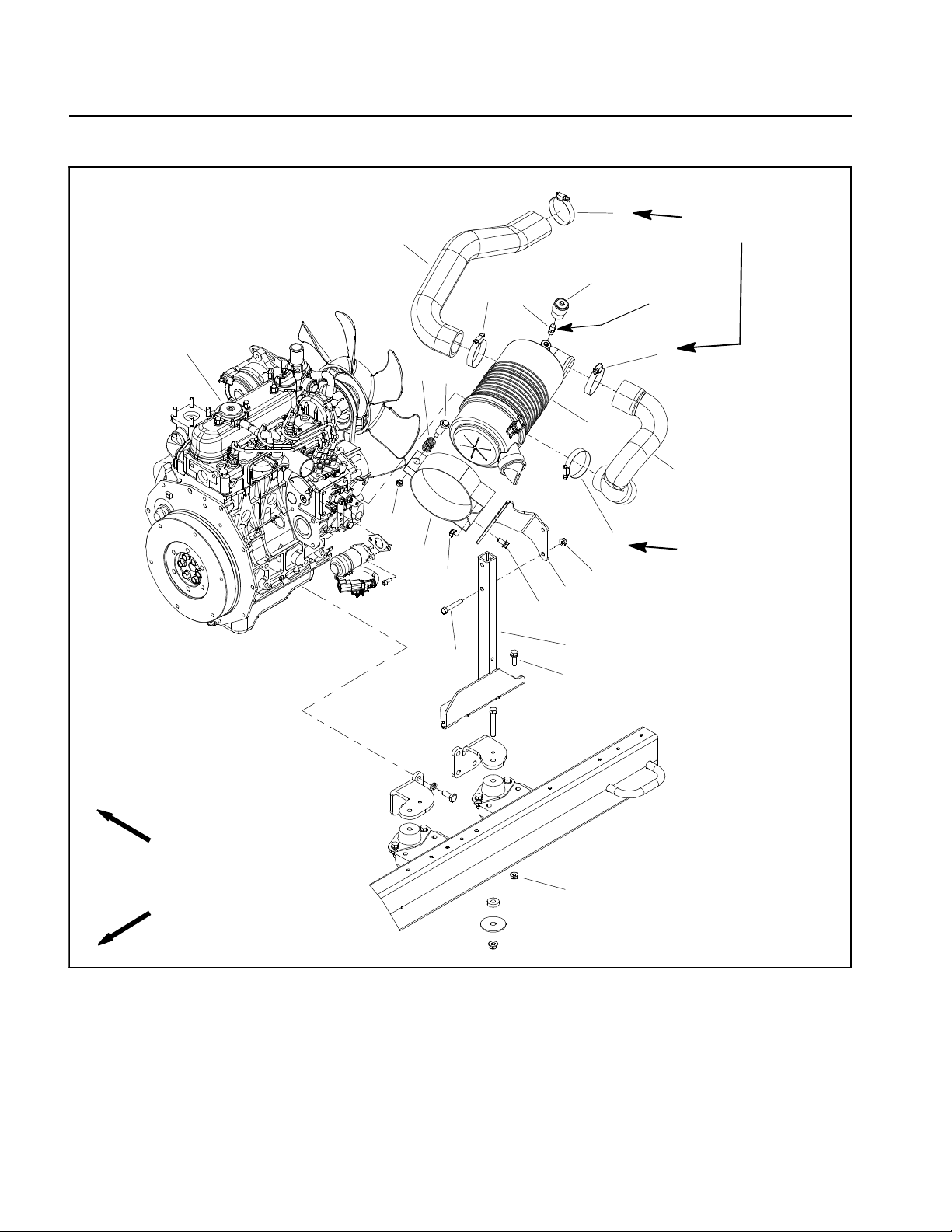
Air Cleaner Assembly
3
5
3
7
1
10
8
9
11
12
13
14
6
2
3
12
16
17
15
30 to 40 in- lb
(3.4 to 4.5 N- m)
Thread
Sealant
3
4
30 to 40 in- lb
(3.4 to 4.5 N- m)
RIGHT
FRONT
1. Diesel engine
2. Air cleaner assembly
3. Hose clamp (4 used)
4. Air intake hose
5. Air intake hose
6. Service indicator
Figure 2
7. Indicator adapter
8. Shoulder bolt
9. Nut
10. Compression spring
11. Air cle aner mounting band
12. Flange nut (6 used)
12
13. Flange head screw (2 used)
14. Cap screw (2 used)
15. Flange head screw (2 used)
16. Air cleaner bracket
17. Air cleaner stand
Reelmaster 5010- HPage 3 - 4Kubota Diesel Engine
Page 23

Removal (Fig. 2)
1. Park machine on a level surface, lower cutting units,
stop engine, engage parking brake and remove key
from the ignition switch. Raise and support hood.
2. Remove air cleaner components as needed using
Figure 2 as a guide.
12 to 15 in- lb
(1.4 to 1.6 N- m)
2
3. See Traction Unit Operator’s Manual for air cleaner
service and maintenance procedures.
Installation (Fig. 2)
IMPORTANT: Any leaks in the air filter system will
allow dirt into engine and will cause serious engine
damage. Make sure that all air cleaner components
arein good condition and are properly secured during assembly.
1. Assemble air cleaner system using Figure 2 as a
guide.
A. If service indicator (item 6 in Fig. 2) and adapter
(item 7 in Fig. 2) were removed from air cleaner
housing, apply thread sealant to adapter threads before installing adapter and indicator to housing.
Install adapter so that grooves in adapter hex and
adapter filter element are installed toward service indicator (shown in Fig. 3). Torque indicator from 12 to
15 in- lb (1.4 to 1.6 N- m).
B. Make sure that evacuator valve on air cleaner assembly is pointed down after assembly.
1
1. Air cleaner assembly
2. Service indicator
3
Thread
Sealant
Engine
Kubota Diesel
4
Figure 3
3. Indicator adapter
4. Evacuator valve
C. T orque hose clamps from 30 to 40 in- lb (3.4 to
4.5 N- m).
2. After air cleaner has been properly installed, lower
and secure hood.
Reelmaster 5010- H Page 3 - 5 Kubota Diesel Engine
Page 24
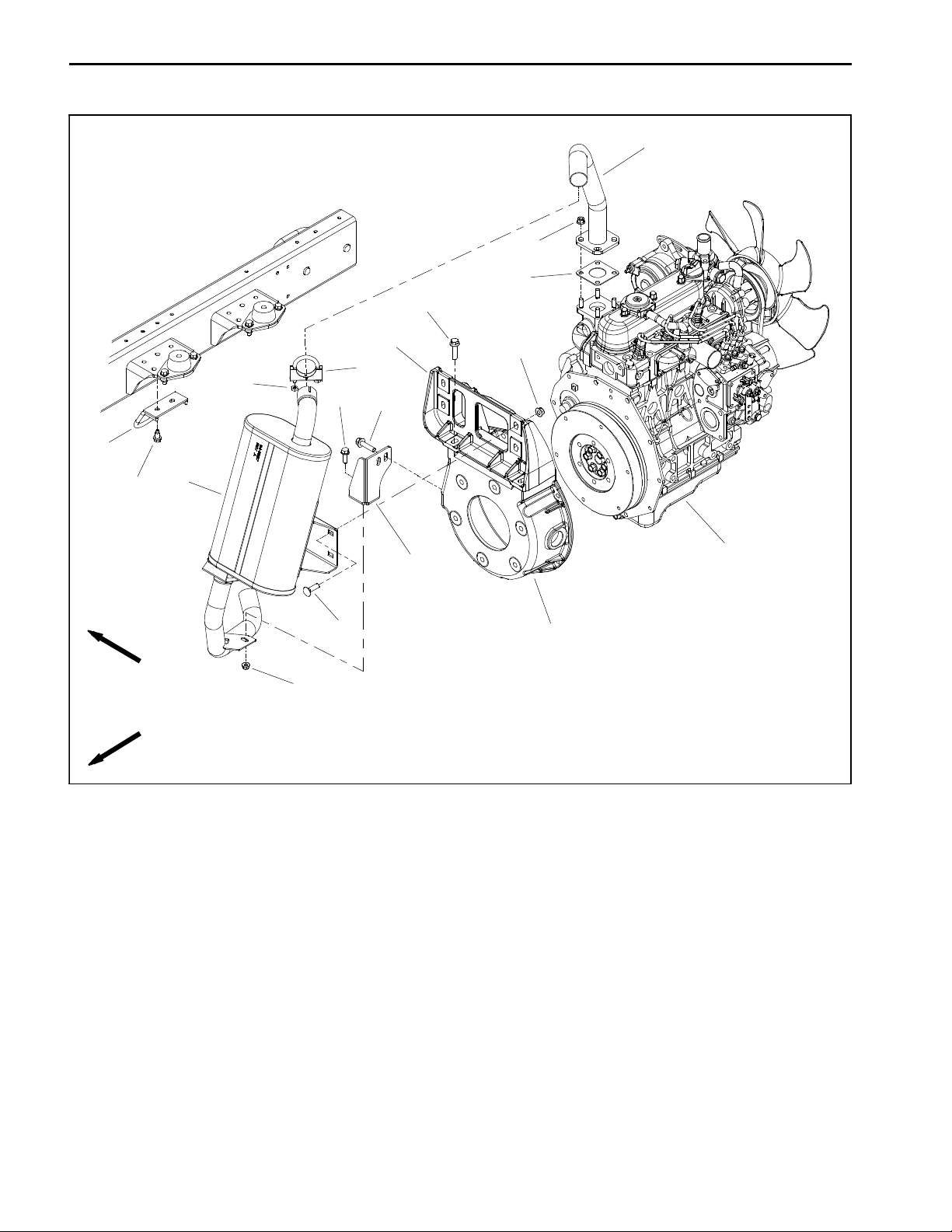
Exhaust System
11
12
13
14
15
16
RIGHT
FRONT
17
5
3
4
9
14
2
1
8
6
7
10
1. Diesel engine
2. Exhaust muffler
3. Clamp
4. Hex nut (2 used)
5. Flange nut (4 used)
6. Carriage bolt (4 used)
Figure 4
7. Bellhousing
8. Tailpipe bracket
9. Flange head screw
10. Flange nut
11. Exhaust header
12. Flange nut (4 used)
13. Exhaust gasket
14. Flange head screw (6 used)
15. Muffler guard
16. Washer head screw (2 used)
17. Muffler bracket
Reelmaster 5010- HPage 3 - 6Kubota Diesel Engine
Page 25

Removal (Fig. 4)
CAUTION
The muffler and exhaust pipe may be hot. To
avoid possible burns, allow the engine and exhaust system to cool before working on the exhaust system.
1. Raise and support hood to gain access to exhaust
system. Allow engine and exhaust system to cool before
doing any disassembly of exhaust system components.
2. Remove exhaust system components from the engine as necessary using Figure 4 as a guide. Discard exhaust gasket (item 13) if exhaust header (item 11) was
removed.
Installation (Fig. 4)
IMPORTANT: If exhaust studs were removed from
engine cylinder head, thoroughly clean threads in
head and apply Loctite #277 (or equivalent) to stud
threads before installing studs into head.
3. Adjust muffler guard (item 15) on frame so there is
⅜” (9.5 mm) clearance between exhaust tailpipe and
guard in all directions.
4. After all exhaust components have been installed,
lower and secure hood.
D
C
B
A
Engine
Kubota Diesel
E
NOTE: Make sure that all exhaust system flanges and
sealing surfaces are free of debris or damage that may
prevent a tight seal.
1. Install new exhaust gasket (item 13) if gasket was
removed. Do not use any type of gasket sealant on gasket or flange surfaces.
2. Install all removed exhaust system components using Figure 4 as a guide. Hand tighten exhaust system
fasteners and after all exhaust system components
have been installed, fully tighten the fasteners as shown
in Figure 5:
A. Tighten flange head screws that secure muffler
bracket to engine bellhousing.
B. Tighten carriage screws and flange nuts that secure exhaust muffler to muffler bracket.
C. Tighten flange nuts that secure exhaust header
to engine exhaust manifold.
D. Tighten clamp that secures exhaust muffler to exhaust header.
F
Figure 5
E. Tighten flange head screw and flange nut that secures exhaust muffler to tailpipe bracket.
F. Tighten flange head screws that secure tailpipe
bracket to engine bellhousing.
Reelmaster 5010- H Page 3 - 7 Kubota Diesel Engine
Page 26
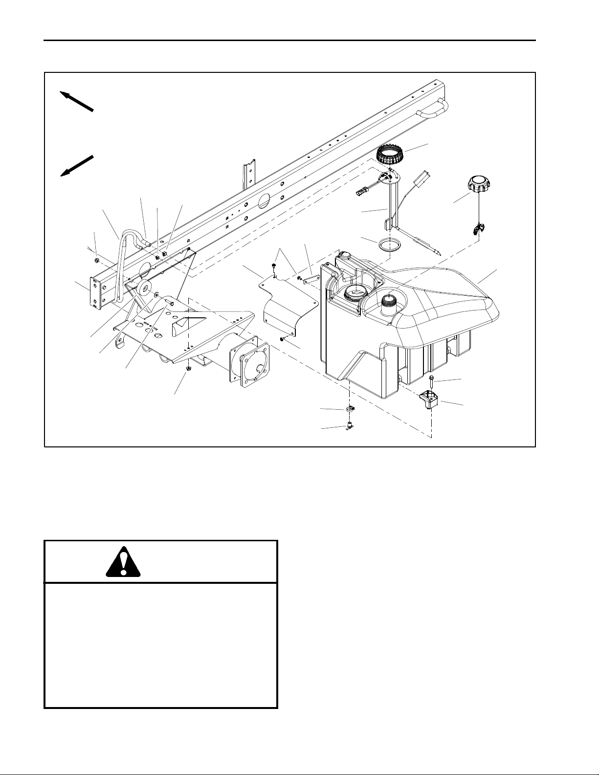
Fuel System
RIGHT
FRONT
9
12
17
16
15
18
7
6
8
19
12
4
3
5
3
14
20
2
1
11
10
1. Fuel tank
2. Fuel tank cap
3. Screw (7 used)
4. Strap
5. Sender cover
6. Hose clamp
7. Fuel supply hose
8. Hose clamp
9. Fuel return hose
10. Clamp (2 used)
11. Flange head screw (2 used)
12. Flange nut (3 used)
13. Draincock
14. Hose clamp
DANGER
Because diesel fuel is flammable, use caution
when storing or handling it. Do not smoke while
filling the fuel tank. Do not fill fuel tank while engine is running, when engine is hot or when machine is in an enclosed area. Always fill fuel tank
outside and wipe up any spilled diesel fuel before starting the engine. Store fuel in a clean,
safety- approved container and keep container
cap in place. Use diesel fuel for the engine only;
not for any other purpose.
13
Figure 6
15. Cap screw
16. Flat washer
17. Bumper
18. Fuel sender cap
19. Fuel sender
20. Gasket
Check Fuel Lines and Connections
Check fuel lines and connections periodically as recommended in the Traction Unit Operator’s Manual. Check
lines for deterioration, damage, leakage or loose connections. Replace fuel hoses, clamps and connections
as necessary.
Drain and Clean Fuel Tank
Drain and clean the fuel tank periodically as recommended in the Traction Unit Operator’s Manual. Also,
drain and clean the fuel tank if the fuel system becomes
contaminated or if the machine is to be stored for an extended period.
Reelmaster 5010- HPage 3 - 8Kubota Diesel Engine
Page 27
IMPORTANT: Follow all local codes and regulations when recycling or disposing waste fuel.
To clean fuel tank, flush tank out with clean diesel fuel.
Make sure tank is free of all contaminates and debris.
Fuel Tank Installation (Fig. 6)
1. Install fuel tank to frame using Figure 6 as a guide.
Secure fuel hoses with cable ties as noted during fuel
tank removal.
Priming the Fuel System
The fuel system needs to be primed before starting the
engine for the first time, after running out of fuel or after
fuel system maintenance (e.g. draining the filter/water
separator, replacing a fuel hose). To prime the fuel system, make sure that the fuel tank has fuelin it. Then,turn
the ignition key to the RUN position for ten (10) to fifteen
(15) seconds which allows the fuel pump to prime the
fuel system. DO NOT use the engine starter motor to
crank the engine in order to prime the fuel system.
Fuel Tank Removal (Fig. 6)
1. Park machine on a level surface, lower cutting units,
stop engine, engage parking brake and remove key
from the ignition switch.
2. Place drain pan under fuel tank. Make sure that drain
pan is large enough to hold fuel tank contents (see
Specifications in this chapter).
3. Open draincock on bottom of fuel tank and allow tank
to fully drain. Close draincock.
4. Disconnect wire harness connection from the fuel
sender (item 19).
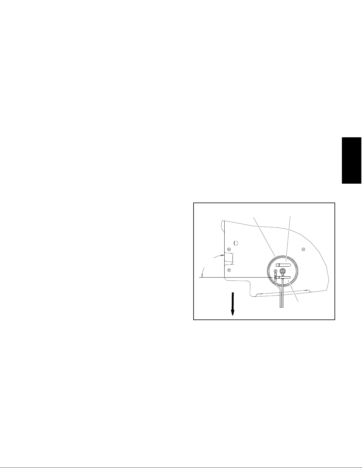
A. If fuel sender was removed from fuel tank, make
sure that fuel fittings on sender are orientated at 90
from right side of tank as shown in Figure 7. Also, to
prevent damage to fuel sender during assembly,
make sure that fuel sender does not turn as sender
cap is tightened.
2. Correctly connect supply (item 7) and return (item 9)
fuel hoses to fittings on the top of thefuel sender. Secure
fuel hoses with hose clamps.
3. Secure wire harness connector to fuel sender.
4. Make sure that fuel tank draincock is closed. Fill fuel
tank with clean fuel.
5. Prime the fuel system (see above).
6. Before returning machine to operation, make sure
that no fuel leaks exist.
1
2
o
Engine
Kubota Diesel
NOTE: Before removing fuel hoses from tank fittings,
label hoses for assembly purposes.
IMPORTANT: T o prevent damage to fuel hoses, numerous cable ties are used to secure hoses to machine components. Take note of all cable ties that
are removed from machine during fuel tank removal
so they can be properly replaced during tank installation.
5. Loosen hose clamps and carefully disconnect supply (item 7) and return (item 9) fuel hoses from fittings
on the top of the fuel sender.
6. Remove fuel tank using Figure 6 as a guide.
IMPORTANT: If fuel sender is removed from fuel
tank, note orientation of fittings for assembly purposes (Fig. 7).
o
90
FRONT
1. Fuel sender
2. Fuel supply fitting
3
Figure 7
3. Fuel return fitting
Reelmaster 5010- H Page 3 - 9 Kubota Diesel Engine
Page 28
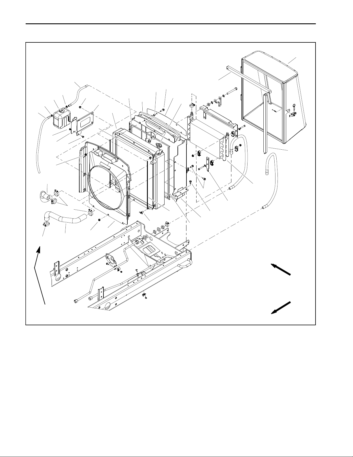
Radiator Assembly
11
6
14
12
13
15
9
2
1
2
10
21
3
28
18
8
2
26
20
25
4
10
23
5
27
7
17
16
24
7
22
10
29
31
19
30
30 to 40 in- lb
(3.4 to 4.5 N- m)
1. Coolant reservoir
2. Hose clamp (3 used)
3. Hose
4. Foam seal (2 used)
5. Oil cooler
6. Hose
7. Hose clamp (4 used)
8. Foam seal (2 used)
9. Radiator cap
10. Flange nut (14 used)
11. Rear screen
Figure 8
12. Foam seal
13. Spacer (5 used)
14. Flange head screw (5 used)
15. Air intake screen
16. Draincock
17. Foam seal (2 used)
18. Radiator
19. Radiator frame
20. Reservoir bracket
21. Reservoir bracket
RIGHT
FRONT
22. Upper radiator hose
23. Lower radiator hose
24. Fan shroud
25. Flange head screw
26. Lock nut
27. Flange head screw (9 used)
28. Foam seal (2 used)
29. Foam seal (2 used)
30. Mount plate (2 used)
31. Washer head screw (6 used)
Reelmaster 5010- HPage 3 - 10Kubota Diesel Engine
Page 29

Removal (Fig. 8)
1. Park machine on a level surface, lower cutting
decks, stop engine, apply parking brake and remove
key from the ignition switch.
2. Unlatch rear screen, lift screen from hinges and remove screen from machine.
3. Remove 12 volt battery from rear of machine to ease
oil cooler removal (see 12 VDC Battery Service in the
Service and Repairs section of Chapter 5 - Electrical
System).
4. Rotate clamps that secure oil cooler to radiator
frame. Carefully lift and remove oil cooler from radiator
frame. Position and support oil cooler away from the radiator.
5. Raise and support the hood.
CAUTION
Do not open radiator cap or drain coolant if the
radiator or engine is hot. Pressurized, hot coolant can escape and cause burns.
30 to 40 in- lb
(3.4 to 4.5 N- m)
RIGHT
FRONT
2
1. Fan shroud
2. Air cleaner intake hose
3. Hose clamp
3
4
30 to 40 in- lb
(3.4 to 4.5 N- m)
Figure 9
4. Generator intake hose
5. Hose clamp
1
5
Engine
Kubota Diesel
Ethylene- glycol antifreeze is poisonous. Dispose of coolant properly, orstore it in a properly
labeled container away from children and pets.
6. Drain radiator into a suitable container either by using the draincock (item 16) on the left side of the radiator
or by disconnecting the lower radiator hose from the radiator. Make sure that drain container is large enough to
hold cooling system contents (see Specifications in this
Chapter).
IMPORTANT: Follow all local codes and regulations when recycling or disposing engine coolant.
7. Disconnect air cleaner and motor/generator intake
hoses from fan shroud (Fig. 9).
8. Disconnect radiator hoses (upper and lower) from
the radiator.
9. At rear of radiator frame, carefully cut the upright
foam seals (item 4) at the junction of the radiator frame
and the machine frame. This will allow the radiator frame
to be removed from the machine without removing the
foam seal from the radiator and machine frames.
10.Remove six (6) washer head screws (item 31) that
secure the radiator frame (item 19) to the frame.
1 1.Carefully raise radiator assembly (radiator, fan
shroud, coolant reservoir and radiator frame) from the
machine.
12.Plug radiator and hose openings to prevent contamination.
13.Disassemble radiator assembly as needed using
Figure 8 as a guide.
Installation (Fig. 8)
1. Inspect all foam seals placed between radiator, fan
shroud and radiator frame. Replace damaged foam
seals.
2. Remove plugs placed in radiator and hose openings
during the removal procedure.
3. Install all removed components to radiator frame using Figure 8 as a guide.
4. Carefully lower radiator assembly with radiator, fan
shroud, coolant reservoir and radiator frame to the machine frame.
5. Secure the radiator frame (item 19) to the frame with
six (6) washer head screws (item 31).
6. Make sure that at least 0.250” (6.4 mm) clearance
exists at all points between fan shroud opening and fan.
7. Connect upper and lower radiator hoses to radiator
and secure with hose clamps. Torque hose clamps from
30 to 40 in- lb (3.4 to 4.5 N- m).
Reelmaster 5010- H Page 3 - 11 Kubota Diesel Engine
Page 30

8. Connect air cleaner and motor/generator intake
hoses to fan shroud and secure with hose clamps (Fig.
9). Torque hose clamps from 30 to 40 in- lb (3.4 to 4.5
N- m).
9. Make sure radiator draincock is closed (threadedout
fully).
12.Carefully position and install oil cooler to radiator
frame. Rotate clamps to secure oil cooler to radiator
frame.
13.Install 12 volt battery (see 12 VDC Battery Service
in the Serviceand Repairs sectionof Chapter5 - Electrical System).
10.Fill radiator and coolant reservoir with coolant.
1 1.Lower and secure hood.
14.Install and latch rear screen.
Reelmaster 5010- HPage 3 - 12Kubota Diesel Engine
Page 31

This page is intentionally blank.
Engine
Kubota Diesel
Reelmaster 5010- H Page 3 - 13 Kubota Diesel Engine
Page 32

Engine
34
33
11
26
45
30 to 40 in- lb
(3.4 to 4.5 N- m)
22
Thread
Sealant
18
14
25
35
22
16
23
22
19
32
12
46
44
24
27
3
44
15
1
17
6
42
41
40
29
37
36
39
30
43
2
7
31
28
22
7
20
21
3
5
9
13
10
7
RIGHT
FRONT
1. Diesel engine
2. Cap screw (12 used)
3. Flange head screw (4 used)
4. Snubbing washer (4 used)
5. Cap screw (4 used)
6. Flange nut (8 used)
7. Flange nut (8 used)
8. Spacer (4 used)
9. Lock washer (12 used)
10. Engine mount (2 used)
11. RH engine mount
12. Exhaust gasket
13. Bellhousing
14. Flange nut (4 used)
15. Tailpipe bracket
16. Service indicator
34 to 42 ft- lb
(47to56N-m)
Figure 10
17. Air cleaner assembly
18. Air intake hose
19. Air intake hose
20. Air cleaner bracket
21. Air cleaner stand
22. Hose clamp (4 used)
23. Indicator adapter
24. Muffler bracket
25. Exhaust header
26. Exhaust muffler
27. Clamp
28. Flange head screw (2 used)
29. Nut
30. Air cle aner mounting band
31. Cap screw (2 used)
38
7
8
4
6
32. Compression spring
33. Muffler guard
34. Washer head screw (2 used)
35. Temperature sender
36. Socket head screw (2 used)
37. Fuel actuator
38. LH engine mount
39. Extension spring
40. Throttle spring bracket
41. Cap screw
42. Cap screw
43. Fuel actuator gasket
44. Flange head screw (6 used)
45. Carriage bolt (4 used)
46. Shoulder bolt
Reelmaster 5010- HPage 3 - 14Kubota Diesel Engine
Page 33

Engine Removal (Fig. 10)
1. Park machine on a level surface, lower cutting units,
stop engine and remove key from the ignition switch.
Chock wheels to keep the machine from moving.
2. Disconnect negative (- ) and then positive (+) battery
cables from the12 volt battery at the rear of the machine
(see 12 VDC Battery Service in the Service and Repairs
section of Chapter 5 - Electrical System).
FRONT
2
4
1
2
3. Open and support hood.
4. Separate system components from the 48 VDC battery pack by unplugging the 48 VDC battery disconnect.
(see 48 VDC Battery Disconnect in the General Information section of this chapter). This will prevent unexpected 48 VDC system component operation.
5. Remove air cleaner from machine (see Air Cleaner
Assembly in this section).
6. Remove exhaust muffler from machine (see Exhaust System in this section).
CAUTION
Do not open radiator cap or drain coolant if the
radiator or engine is hot. Pressurized, hot coolant can escape and cause burns.
Ethylene- glycol antifreeze is poisonous. Dispose of coolant properly, orstore it in a properly
labeled container away from children and pets.
1. Fuel supply hose
2. Hose clamp
3. Fuel return hose
1
2
3
5
Figure 11
4. Hose clamp
5. Separator
Engine
Kubota Diesel
3
4
7. Drain radiator into a suitable container either by using the draincock on the left side of the radiator or by disconnecting the lower radiator hose from the radiator.
1. Fuel actuator
2. Fuel actuator connector
Figure 12
3. Wire harness ground
4. Negative battery cable
Make sure that drain container is large enough to hold
cooling system contents (see Specifications in this
Chapter).
IMPORTANT: Follow all local codes and regula-
2
tions when recycling or disposing engine coolant.
8. Disconnect hoses from engine:
2
A. Loosen clamps and remove upper and lower radiator hoses from the engine.
B. Disconnect fuel supply and return hoses from en-
3
1
4
gine (Fig. 11).
5
C. Plug disconnected hoses and engine openings to
prevent leakage and contamination. Positiondisconnected hoses away from engine.
Figure 13
1. Engine mount (4 used)
2. Screw (2 per mount)
3. Nut (2 per mount)
3
4. Lock washer
5. Ground cable
Reelmaster 5010- H Page 3 - 15 Kubota Diesel Engine
Page 34

9. Disconnect hydraulic pump drive shaft from 48 VDC
motor/generator (see Hydraulic Pump Drive Shaft in the
Service and Repairs section of Chapter 4 - Hydraulic
System). Position and support drive shaft away from
motor/generator and engine.
IMPORTANT: T o prevent damage to electrical wire
harness, numerous cable ties are used to secure
harness to machine components. Take note of all
cable ties that are removed from machine during
engine removal so they can be properly replaced
during engine installation.
10.Note location of cable ties used to secure wire harness to the machine for assembly purposes. Disconnect
wires and/or electrical connections from the following
engine electrical components:
IMPORTANT: Make sure to not damage the engine,
fuel hoses, hydraulic lines, electrical harness, radiator or other parts while removing the engine.
13.Carefully raise engine from machine moving it toward thefront of the machine and away from radiator assembly.
14.If necessary, remove engine mount brackets from
engine.
15.If necessary, remove engine mounts from machine
frame (Fig. 13). Note that front engine mount on left side
of machine has the negative battery cable ground connection secured with one of the mount bolts. If removed,
make sure to locate lock washer that should be installed
between the cable connection and the frame.
A. The wire harness connectors from the alternator,
temperature sender, oil pressure switch, starter motor solenoid and fuel actuator.
B. The wire harness ring terminals from the alternator and glow plug bus.
C. The positive battery cable and fusible link harness from the engine starter motor.
D. The negative battery cable and wire harness
ground at the engine block under the fuel actuator
(Fig. 12).
E. The wire harness connector from the 48 VDC
motor/generator assembly.
CAUTION
Make sure that hoist or lift used to remove engine assembly can properly support engine and
attached components. Engine assembly weighs
approximately 280 pounds (127 kg).
1 1.Connect suitable lift or hoist to the lift brackets on
each end of the engine cylinder head.
12.Remove flange nuts, rebound washers, spacers and
cap screws that secure the engine mount brackets to
the engine mounts.
16.If necessary, remove 48 VDC motor/generator from
engine (see 48 VDC Motor/Generator Assembly in the
Service and Repairs section of Chapter 5 - Electrical
System).
Engine Installation (Fig. 10)
1. Locate machine on a level surface with cutting units
lowered and key removed from the ignition switch.
Chock wheels to keep the machine from moving.
2. Make sure that all parts removed from the engine
during maintenance or rebuilding are installed to the engine.
3. If engine mount brackets were removed from the engine, secure brackets to engine with lock washers and
cap screws. Torque cap screws from 34 to 42 ft- lb (47
to 56 N- m).
4. If removed, install 48 VDC motor/generator and bellhousing assembly to engine (see 48 VDC Motor/Generator Assembly in the Service and Repairs section of
Chapter 5 - Electrical System).
5. If removed, secure engine mounts to frame machine
frame (Fig. 13). Make sure that negative battery cable
ground connection is secured withlock washer between
the cableconnection and theframe if front engine mount
on left side of machine was removed.
6. Connect suitable lift or hoist to the engine lift brackets.
CAUTION
One person should operate hoist or lift while a
second person guides the engine out of the machine.
Reelmaster 5010- HPage 3 - 16Kubota Diesel Engine
Page 35

CAUTION
One person should operate lift or hoist while a
second person guides the engine into the machine.
12.Install air cleaner (see Air Cleaner Assembly in this
section).
13.Install exhaust muffler to machine (see Exhaust System in this section). Make sure that exhaust tube has ⅜”
(9.5 mm) clearance with guard in all directions after assembly.
IMPORTANT: Make sure to not damage the engine,
fuel hoses, hydraulic lines, electrical harness, radiator or other parts while installing the engine.
7. Carefully lower engine to the mounts secured to the
machine frame. Make sure fastener holes of the engine
mount brackets are aligned with the holes in the engine
mounts.
8. Insert cap screw down through each engine mount
bracket and mount. Place spacer, snubbing washer and
then flange nut on four (4) cap screws. Tighten fasteners
to secure engine to engine mounts.
9. Connect hydraulic pump drive shaft to motor/generator output shaft (see Hydraulic Pump Drive Shaft in the
Service and Repairs section of Chapter 4 - Hydraulic
System).
10.Connect all wire harness connectors to correct engine components. Secure wire harness to the machine
with cable ties in locations noted during engine removal.
1 1.Remove plugs installed in fuel and coolant hoses
and engine openings during disassembly. Connect
hoses to the engine:
14.Make sure radiator draincock isclosed (threaded out
fully). Fill radiator and coolant reservoir with coolant.
15.Check engine oil level and adjust if needed.
16.Check and adjust oil level in hydraulic reservoir as
needed.
17.Plug the 48 VDC battery disconnect back in.
18.Close and secure hood.
19.Connect positive (+) and then negative (- ) battery
cables to the 12 volt battery (see 12 VDC Battery Service in the Service and Repairs section of Chapter 5 Electrical System).
20.Prime the fuel system (see Fuel System in t his section).
21.Start engine and operate hydraulic controls to properly fill hydraulic system (see Charge Hydraulic System
in the Service and Repairs section of Chapter 4 - Hydraulic System).
Engine
Kubota Diesel
A. Connect fuel supply and fuel return hoses to engine fittings (Fig. 11). Secure fuel hoses with hose
clamps.
B. Connect upper and lower radiator hoses to the
engine. Secure hoses with hose clamps. Torque
hose clamps from 30 to 40 in- lb (3.4 to 4.5 N- m).
Reelmaster 5010- H Page 3 - 17 Kubota Diesel Engine
Page 36

Engine Bellhousing Assembly
20
50 to 60 ft- lb
(68to81N-m)
1
Antiseize
Lubricant
2
19
16
18
7
9
8
5
4
17
11
15
Antiseize
Lubricant
14
3
6
10
12
13
25 to 31 ft- lb
(34to42N-m)
RIGHT
FRONT
1. Diesel engine
2. Motor/generator assembly
3. Flange head screw
4. Collar
5. Coupler hub
6. Woodruff key
7. Bellhousing
8. Cap screw (2 used)
9. Flat washer (2 used)
10. Flange head screw (7 used)
11. Flange nut (2 used)
12. R - clamp (for generator wire harness)
13. Clamp (for fuel return hose)
14. Caplug
The 48 VDC motor/generator is attached to the engine
bellhousing with six (6) flange head screws. Access to
these screws requires the bellhousing and motor/generator to be removed from the engine as an assembly. For
recommended procedures to remove the bellhousing
and motor/generator assembly from the engine, see 48
VDC Motor/Generator Assembly in the Service and Repairs section of Chapter 5 - Electrical System.
Figure 14
15. Flange head screw (6 used)
16. Dowel pin (2 used)
17. Coupler flange
18. Socket head screw (3 used)
19. Muffler bracket
20. Flange head screw (4 used)
Reelmaster 5010- HPage 3 - 18Kubota Diesel Engine
Page 37

Table of Contents
Chapter 4
Hydraulic System
SPECIFICATIONS 2............................
GENERAL INFORMATION 3.....................
Traction Unit Operator’s Manual 3..............
48 VDC Battery Disconnect 3..................
Check Hydraulic Fluid 3.......................
Towing Traction Unit 4.........................
Hydraulic Hoses 4............................
Hydraulic Hose and Tube Installation 5..........
Hydraulic Fitting Installation 6..................
Relieving Hydraulic System Pressure 8..........
Traction Circuit Component Failure 8............
HYDRAULIC SCHEMATIC 10....................
HYDRAULIC FLOW DIAGRAMS 12...............
Traction Circuit 12............................
Lift Circuit: Raise Cutting Units 14...............
Lift Circuit: Lower Cutting Units 16..............
Steering Circuit 18............................
SPECIAL TOOLS 20............................
TROUBLESHOOTING 25........................
General Hydraulic System Problems 25..........
Traction Circuit Problems 26...................
Lift Circuit Problems 27........................
Steering Circuit Problems 28...................
TESTING 30...................................
Traction Circuit Relief Valve (R3) and (R4)
Pressure Test 32............................
Traction Circuit Charge Pressure Test 34.........
Gear Pump (P2) Flow Test 36..................
Front Wheel Motor Efficiency Test 38............
Piston (Traction) Pump Flow Test 40............
Lift Relief Valve (SVRV) Pressure Test 42........
Gear Pump (P1) Flow Test 44..................
Lift Cylinder Internal Leakage Test 46............
Steering Relief Valve (R10) Pressure Test 48.....
Steering Cylinder Internal Leakage Test 50.......
SERVICE AND REPAIRS 52.....................
General Precautions for Removing and Installing
Hydraulic System Components 52.............
Check Hydraulic Lines and Hoses 53............
Flush Hydraulic System 54.....................
Filtering Closed- Loop Traction Circuit 55........
Hydraulic System Start- up 56..................
Hydraulic Reservoir 58........................
Piston (Traction) Pump Control Assembly 60.....
Hydraulic Pump Assembly 62..................
Piston (Traction) Pump Service 66..............
Gear Pump Service 68........................
Hydraulic Pump Drive Shaft 70.................
Hydraulic Pump Drive Shaft Cross and
Bearing Service 72..........................
Front Wheel Motors 74........................
Front Wheel Motor Service 76
Rear Wheel Motors (Machines with Optional
CrossTrax
Rear Wheel Motor Service (Machines with Optional
CrossTrax
Control Manifold Cartridge Valve Service 81......
Lift Control Manifold 82........................
Lift Control Manifold Service 84.................
CrossTrax
Optional CrossTrax
CrossTrax
with Optional CrossTrax
Lift Cylinders 90..............................
Lift Cylinder Service 92........................
Steering Control Valve 94......................
Steering Control Valve Service 96...............
Steering Cylinder 98..........................
Steering Cylinder Service 100..................
Hydraulic Oil Cooler 102.......................
SAUER- DANFOSS LPV CLOSED CIRCUIT AXIAL
PISTON PUMPS REPAIR MANUAL
SAUER- DANFOSS LPV CLOSED CIRCUIT AXIAL
PISTON PUMPS SERVICE INSTRUCTIONS
EATON DELTA MOTORS PARTS AND REPAIR
MANUAL
PARKER TORQMOTOR
(TC, TB, TE, TJ, TF, TG, TH AND TL SERIES)
SAUER- DANFOSS STEERING UNIT TYPE OSPM
SERVICE MANUAL
TM
Kit) 78.........................
TM
Kit) 80.........................
TM
AWD Manifold (Machines with
TM
AWD Manifold Service (Machines
..................
TM
Kit) 86.................
TM
Kit) 88.............
TM
SERVICE PROCEDURE
System
Hydraulic
Reelmaster 5010- H Hydraulic SystemPage 4 - 1
Page 38

Specifications
Item Description
Piston (Traction) Pump Closed Circuit Axial Piston Design
Maximum Pump Displacement (per revolution) 2.14 Cubic Inches (35 cc)
Gear Pump 2 Section, Positive Displacement Gear Type Pump
Section P1 Displacement (per revolution) (all models) 0.24 Cubic Inches (3.96 cc)
Section P2 Displacement (per revolution) (all models) 0.40 Cubic Inches (6.61 cc)
Charge Circuit Relief (R5) Pressure 200PSI(14bar)
Traction Circuit Relief Pressure: Forward (R3) and Reverse (R4) 3625 PSI (250 bar)
Front Wheel Motors Geroler Motor
Displacement (per revolution) 24.7 in
Rear Wheel Motors (if equipped) Rotor Motor
Displacement (per revolution) 19.0 in
Steering Valve Hydrostatic Steering Unit, Open Center
Displacement (per revolution) 6.1 in
Steering Circuit Relief (R10) Pressure 1000 PSI (70 bar)
Lift Circuit Relief (SVRV) Pressure 2000 PSI (138 bar)
Lift Circuit Lower Relief (R7) Pressure 500PSI(35bar)
Hydraulic Filter (Steering Circuit) Spin- on Cartridge Type with 25 PSI (1.7 bar) Relief in Adapter
Hydraulic Oil See Traction Unit Operator’s Manual
Hydraulic Reservoir Capacity 11 U.S. Gallons (41.6 L)
3
(405 cc)
3
(310 cc)
3
(100 cc)
Reelmaster 5010- HHydraulic System Page 4 - 2
Page 39

General Information
Traction Unit Operator’s Manual
The Traction Unit Operator’s Manual provides information regarding the operation, general maintenance and
maintenance intervals for your Reelmaster m achine.
Refer to that publication for additional information when
servicing the machine.
48 VDC Battery Disconnect
CAUTION
Before installing, removing or servicing components in the 48 VDC system (e.g. cutting unit motors, motor/generator), separate the 48 VDC battery disconnect. This will prevent unexpected
operation of 48 VDC system components.
The 48 VDC battery disconnect is attached to the r ight
frame rail under the operator seat (Fig. 1). Unplug the
disconnect to make sure that 48 VDC components do
not operate unexpectedly. Apply dielectric grease to the
contact surfaces of the battery disconnect and plug the
battery disconnect back in after service to the 48 VDC
system is completed.
FRONT
1
1. RH frame rail 2. 48V battery disconnect
2
Figure 1
System
Hydraulic
Check Hydraulic Fluid
The hydraulic system on Reelmaster 5010- H machines
is designed to operate on high quality hydraulic fluid.
The hydraulic system reservoir holds approximately 11
gallons (41.6 liters) of hydraulic fluid. Check level of hy-
draulic fluid daily. See Traction Unit Operator’s Manual for fluid level checking procedure and hydraulic oil
recommendations.
Reelmaster 5010- H Hydraulic SystemPage 4 - 3
1
2
Figure 2
1. Hydraulic reservoir 2. Cap with dipstick
Page 40

Towing Traction Unit
IMPORTANT: If towing limits are exceeded, severe
damage to the piston (traction) pump may occur.
If it becomes necessary to tow or push the machine, tow
or push at a speed below 3 mph (4.8 kph), and for a very
short distance. If the machine needs to be moved a considerable distance, machine should be transported on a
trailer. The piston (tracti on)pumpisequippedwithabypass valve that needs to be loosened for towing or pushing (Fig. 3). See Traction Unit Operator’s Manual for
Towing Procedures.
Hydraulic Hoses
Hydraulic hoses are subject to extreme conditions such
as pressure differentials during operation and exposure
to weather, sun, chemicals, very warm storage conditions or mishandling during operation and maintenance.
These conditions can cause hose damage and deterioration. Some hoses are more susceptible to these
conditions than others. Inspect all machine hydraulic
hoses frequently for signs of deterioration or damage:
1
2
Figure 3
1. Piston (traction) pump 2. Bypass valve
WARNING
Before disconnecting or performing any work on
hydraulic system, relieve all pressure in system
(see Relieving Hydraulic System Pressure in this
section).
Hard, cracked, cut, abraded, charred, leaking or
otherwise damaged hose.
Kinked, crushed, flattened or twisted hose.
Blistered, soft, degraded or loose hose cover.
Cracked, damaged or badly corroded hose fittings.
When replacing a hydraulic hose, be sure that the hose
is straight (not twisted) before tightening the fittings.
This can be done by observing the imprint (layline) on
the hose. Use two wrenches when tightening a hose;
hold the hose straight with one wrench and tighten the
hose swivel nut onto the fitting with the second wrench
(see Hydraulic Hose and Tube Installation in this section). If the hose has an elbow at one end, tighten the
swivel nut on that end before tightening the nut on the
straight end of the hose.
For additional hydraulic hose information, refer to Toro
Service Training Book, Hydraulic Hose Servicing (Part
Number 94813SL).
Keep body and hands away from pin hole leaks or
nozzles that eject hydraulic fluid under high
pressure. Use paper or cardboard, not hands, to
search for leaks. Hydraulic fluid escaping under
pressure can have sufficient force to penetrate
the skin and cause serious injury. If fluid is injected into the skin, it must be surgically removed within a few hours by a doctor familiar
with this type of injury. Gangrene may result from
such an injury.
Reelmaster 5010- HHydraulic System Page 4 - 4
Page 41

Hydraulic Hose and Tube Installation (O- Ring Face Seal Fitting)
1. Make sure threads and sealing surfaces of the hose/
tube and the fitting are free of burrs, nicks, scratches or
any foreign material.
2. As a preventative measure against leakage, it is recommended that the face seal O - ring be replaced any
time the connection is opened. Make sure the O - ring is
installed and properly seated in the fitting groove. Lightly
lubricate the O- ring with clean hydraulic oil.
3. Place the hose/tube against the fitting body so that
the flat face of the hose/tube sleeve fully contacts the Oring in the fitting.
4. Thread the swivel nut onto the fitting by hand. While
holding the hose/tube with a wrench, use a torque
wrench to tighten the swivel nut to the recommended
installation torque shown in Figure 6. This tightening
process will require the use of an offset wrench (e.g.
crowfoot wrench). Use of an offset wrench will affect
torque wrench calibration due to the effective length
change of the torque wrench. Tightening torque when
usingatorquewrenchwithanoffsetwrenchwillbelower
than the listed installation torque (see Using a Torque
Wrench with an Offset Wrench in the Torque Specifications section of Chapter 2 - Product Records and Maintenance).
C. Useasecondwrenchtotightenthenuttothecorrect Flats From Wrench Resistance (F.F.W.R.). The
markings on the nut and fitting body will verify that the
connection has been properly tightened.
Siz e F.F.W .R.
4 (1/4 in. nominal hose or tubing) 1/2 to 3/4
6 (3/8 in.) 1/2 to 3/4
8 (1/2 in.) 1/2 to 3/4
10 (5/8 in.) 1/2 to 3/4
12 (3/4 in.) 1/3 to 1/2
16 (1 in.) 1/3 to 1/2
Swivel Nut
Tub e or Hose
O- ring
Fitting Body
Figure 4
System
Hydraulic
5. If a torque wrench is not available or if space at the
swivel nut prevents use of a torque wrench, an alternate
method of assembly is the Flats From Wrench Resist-
Mark Nut
and Fitting
Body
Final
Position
ance (F.F.W.R.) method (Fig. 2).
A. Using a wrench, tighten the swivel nut onto the fitting until light wrench resistance is reached (approximately 30 in- lb).
B. Mark the swivel nut and fitting body. Hold the
hose/tube with a wrench to prevent it from turning.
AT WRENCH RESISTANCE
Extend Line
Figure 5
Fitting Dash Size Hose/Tube Side Thread Size Installation Torque
4 9/16 - 18 18 to 22 ft- lb (25 to 29 N- m)
6 11/ 16 - 1 6 27 to 33 ft- lb (37 to 44 N- m)
8 13/16 - 16 37 to 47 ft- lb (51 to 63 N- m)
10 1- 14 60 to 74 ft- lb (82 to 100 N- m)
12 13/16- 12 85 to 105 ft- lb (116 to 142 N- m)
16 17/16- 12 110to136ft-lb(150to184N-m)
Initial
Position
AFTER TIGHTENING
20 1 11/16 - 12 140 to 172 ft- lb (190 to 233 N- m)
Figure 6
Reelmaster 5010- H Hydraulic SystemPage 4 - 5
Page 42

Hydraulic Fitting Installation (SAE Straight Thread O- Ring Fitting into Component Port)
Non- Adjustable Fitting (Fig. 7)
1. Make sure all threads and sealing surfaces of fitting
and component port are free of burrs, nicks, scratches
or any foreign material.
2. As a preventative measure against leakage, it is recommended that the O- ring be replaced any time the
connection is opened.
3. Lightly lubricate the O- ring with clean hydraulic oil.
Fitting threads should be clean with no lubricant applied.
IMPORTANT: Before installing fitting into port, determine port material. If fittingistobeinstalledinto
an aluminum port, installation torque is reduced.
4. Install the fitting into the port. Then, use a torque
wrench and socket to tighten the fitting to the recommended installation torque shown in Figure 8.
NOTE: Useofanoffsetwrench(e.g.crowfootwrench)
will affect torque wrench calibration due to the effective
length change of the torque wrench. Tightening torque
when using a torque wrench with an offset wrench will
be less than the recommended installation torque. See
UsingaTorqueWrenchwithanOffsetWrenchinthe
Torque Specifications section of Chapter 2 - Product
Records and Maintenance to determine necessary conversion information.
5. If a torque wrench is not available, or if space at the
port prevents use of a torque wrench, an alternate method of assembly is the Flats From Finger Tight (F.F.F.T.)
method.
A. Install the fitting into the port and tighten it down
full length until finger tight.
B. If port material is steel, tighten the fitting to the
listed F.F.F.T. If port material is aluminum, tighten fitting to 60% of listed F.F.F.T.
Siz e F.F.F. T.
4 (1/4 in. nominal hose or tubing) 1.00 +
6 (3/8 in.) 1.50 +
8 (1/2 in.) 1.50 +
10 (5/8 in.) 1.50 +
12 (3/4 in.) 1.50 +
16 (1 in.) 1.50 +
Fitting
O- ring
0.25
0.25
0.25
0.25
0.25
0.25
Figure 7
Fitting
Dash Size
Fitting Port Side
Thread Size
Installation Torque Into
Steel Port
Installation Torque Into
Aluminum Port
4 7/16 - 20 15 to 19 ft- lb (21 to 25 N- m) 9to11ft-lb(13to15N-m)
5 1/2 - 20 18 to 22 ft- lb (25 to 29 N- m) 11 to 15 ft- lb (15 to 20 N- m)
6 9/16 - 18 34 to 42 ft- lb (47 to 56 N- m) 20 to 26 ft- lb (28 to 35 N- m)
8 3/4 - 16 58 to 72 ft- lb (79 to 97 N- m) 35 to 43 ft- lb (48 to 58 N- m)
10 7/8 - 14 99 to 121 ft- lb (135 to 164 N- m) 60 to 74 ft- lb (82 to 100 N- m)
12 11/16- 12 134to164ft-lb(182to222N-m) 81to99ft-lb(110to134N-m)
14 13/16- 12 160to196ft-lb(217to265N-m) 96 to 118 ft- lb (131 to 160 N- m)
16 15/16- 12 202to248ft-lb(274to336N-m) 121to149ft-lb(165to202N-m)
20 15/8- 12 247to303ft-lb(335to410N-m) 149to183ft-lb(202to248N-m)
Figure 8
Reelmaster 5010- HHydraulic System Page 4 - 6
Page 43

Adjustable Fitting (Fig. 9)
1. Make sure all threads and sealing surfaces of fitting
and component port are free of burrs, nicks, scratches
or any foreign material.
2. As a preventative measure against leakage, it is recommended that the O- ring be replaced any time the
connection is opened.
3. Lightly lubricate the O- ring with clean hydraulic oil.
Fitting threads should be clean with no lubricant applied.
4. Turn back the lock nut as far as possible. Make sure
the back up washer is not loose and is pushed up as far
aspossible(Step1inFigure10).
IMPORTANT: Before installing fitting into port, determine port material. If fitting is to be installed into
an aluminum port, installation torque is reduced.
Lock Nut
Back- up Washer
O- ring
Figure 9
5. Install the fitting into the port and tighten finger tight
until the washer contacts the face of the port (Step 2 in
Figure 10). Make sure that the fitting does not bottom in
the port during installation.
6. To put the fitting in the desired position, unscrew it by
the required amount to align fitting with incoming hose
or tube, but no more than one full turn (Step 3 in Figure
10).
7. Hold the fitting in the desired position with a wrench
and use a torque wrench to tighten the lock nut to the
recommended installation torque shown in Figure 8.
This tightening process will require the use of an offset
wrench (e.g. crowfoot wrench). Use of an offset wrench
will affect torque wrench calibration due to the effective
length change of the torque wrench. Tightening torque
when using a torque wrench with an offset wrench will
be lower than the listed installation torque (see Using a
TorqueWrenchwithanOffsetWrenchintheTorque
Specifications section of Chapter 2 - Product Records
and Maintenance).
8. If a torque wrench is not available, or if space at the
port prevents use of a torque wrench, an alternate m ethod of assembly is the Flats From Finger Tight (F.F.F.T.)
method. Hold the fitting in the desired position with a
wrench and, if port material is steel, tighten the lock nut
withasecondwrenchtothelistedF.F.F.T.(Step4inFigure 10). If port material is aluminum, tighten fitting to
60% o f l isted F. F. F. T.
Step 3Step 1
Step 2 Step 4
Figure 10
System
Hydraulic
Siz e F.F.F. T.
4 (1/4 in. nominal hose or tubing) 1.00 +
6(3/8in.) 1.50+
8(1/2in.) 1.50+
10 (5/8 in.) 1.50 +
12 (3/4 in.) 1.50 +
16 (1 in.) 1.50 +
0.25
0.25
0.25
0.25
0.25
0.25
Reelmaster 5010- H Hydraulic SystemPage 4 - 7
Page 44

Relieving Hydraulic System Pressure
Before disconnecting or performing any work on the hydraulic system, all pressure in the hydraulic system
must be relieved. Park machine on a level surface, lower
cutting units fully, stop engine and engage parking
brake.
To relieve hydraulic pressure in lift circuit, start engine
and fully lower the cutting units. Turn key switch to OFF
and remove key from the ignition switch.
Traction Circuit Component Failure
The traction circuit on Reelmaster 5010- H series machines is a closed loop system that includes the piston
(traction) pump and two (2) front wheel motors (four (4)
wheel motors on machines equipped with optional
CrossTrax
cuit should fail, debris and contamination from the failed
component will circulate throughout the traction circuit.
This contamination can damage other components in
the circuit so it must be removed to prevent additional
component failure.
The recommended method of removing traction circuit
contamination would be to temporarily install the Toro
high flow hydraulic filter (see Special Tools in this chapter) into the circuit. This filter should be used when connecting hydraulic test gauges in order to test traction
circuit components or after replacing a failed traction circuit component (e.g. traction (piston) pump or wheel
motor). The filter will ensure that contaminates are removed from the closed loop and thus, do not cause additional component damage.
Once the Toro high flow hydraulic filter kit has been
placed in the circuit, raise and support the machine with
TM
AWD kit). If a component in the traction cir-
To relieve hydraulic pressure in traction circuit, stop engine and move traction pedal to both forward and reverse directions.
To relieve hydraulic pressure in steering circuit, stop engine and rotate steering wheel in both directions.
all wheels off the ground. Then, operate the traction circuit to allow oil flow throughout the circuit. The filter will
remove contamination from the traction circuit during
operation. Because the Toro high flow filter is bi- directional, the traction circuit c an be operated in both the forward and reverse direction. The filter should be
removed from the machine after contamination has
been removed from the traction circuit. See Filtering
Closed- Loop Traction Circuit in the Service and Repairs
section of this chapter for additional information on using the Toro high flow hydraulic filter.
The alternative to using the Torohigh flow hydraulic filter
kitafteratractioncircuitcomponentfailurewouldbeto
disassemble, drain and thoroughly clean all components, hydraulic tubes and hydraulic hoses in the traction circuit. If any debris remains in the traction circuit
and the machine is operated, the debris can cause additional circuit component failure.
NOTE: The piston (traction) pump case drain could allow traction circuit contamination to contaminate other
hydraulic circuits on the machine.
Reelmaster 5010- HHydraulic System Page 4 - 8
Page 45

This page is intentionally blank.
System
Hydraulic
Reelmaster 5010- H Hydraulic SystemPage 4 - 9
Page 46

Hydraulic Schematic
LIFT
CONTROL
MANIFOLD
NOTE: A larger hydraulic schematic is
included in Chapter 9 - Foldout Drawings
Reelmaster 5010- HHydraulic System Page 4 - 10
Page 47

This page is intentionally blank.
System
Hydraulic
Reelmaster 5010- H Hydraulic SystemPage 4 - 11
Page 48

Hydraulic Flow Diagrams
Reelmaster 5010- H
Working Pressure
Traction Circuit (Forward Shown)
Low Pressure (Charge)
Return or Suction
Flow
LIFT
CONTROL
MANIFOLD
Figure 11
Reelmaster 5010- HHydraulic System Page 4 - 12
Page 49

Traction Circuit
The hydraulic traction circuit consists of a variable displacement piston pump (P3) connected in a closed loop,
parallel circuit to two (2) orbital roller vane wheel motors.
The piston (traction) pump input shaft is rotated by a
drive shaft connected to the motor/generator shaft that
is driven by the engine flywheel.
Traction circuit pressure (forward and reverse) can be
measured at test ports located in the hydraulic tubes
that connect the front wheel motors.
NOTE: In high load traction situations, the 48 VDC motor/generator may automatically assist the engine to
maintain piston (traction) pump input speed.
Forward Direction (Fig. 11)
Pushing the top of the traction pedal angles the piston
(traction) pump swash plate to create a flow of oil. This
oil flow is directed to the wheel motors via hydraulic
hoses and tubes to drive the wheels in the forward direction. Forward traction pressure is limited to 3625 PSI
(250 bar) by the forward traction relief valve (R3) located
in the piston (traction) pump.
Oil flowing from the wheel motors returns to the variable
displacement pump and is continuously pumped
through the traction circuit as long as the traction pedal
is pushed.
The angle of the swash plate determines pump flow and
ultimately traction speed. When the traction pedal is depressed a small amount, a small swash plate rotation results in low pump output and lower traction speed. When
the traction pedal is depressed fully, the pump swash
plate rotates fully to provide maximum pump output and
traction speed.
Reverse Direction
The traction circuit operates essentially the same in reverse as it does in the forward direction. However, the
flow through the circuit is reversed. Pushing the bottom
of the traction pedal rotates the piston (traction) pump
swash plate to create a flow of oil. This oil is directed to
the wheel motors to drive the wheels in the reverse
direction. Reverse traction pressure is limited to 3625
PSI (250 bar) by the reverse traction relief valve (R4) located in the piston (traction) pump.
Oil flowing from the wheel motors returns to the piston
(traction) pump and is continuously pumped through the
closed loop traction circuit as long as the traction pedal
is pushed.
The charge circuit and flushing valve function the same
in reverse as they do in the forward direction.
TM
CrossTrax
On machines equipped with the optional CrossTrax
AWD (Optional)
TM
AWD kit, four (4) wheel motors are used (Fig. 12). Piston
(traction) pump flow is directed to the front tires and the
opposite rear tires to maximize traction. To reduce tire
scuffing when turning, traction system pressure is
equalized in the AWD manifold with an orifice and a bidirectional relief valve. Check valves in the AWD manifold allow the rear wheel motors to over run during tight
turns.
CrossTrax AWD Hydraulic Schematic
TM
G5
System
Hydraulic
Gear pump section (P2) supplies oil flow for the steering
circuit and also provides a constant supply of charge oil
totheclosedlooptractioncircuit. This charge oil provides lubrication for traction circuit components and also
replenishes traction circuit oil that is lost due to internal
leakage in the traction circuit.
The hydraulic reservoir provides fluid for the gear pump
(P2) through the suction hose. Charge pump flow is directed to the low pressure side of the closed loop traction circuit. Charge pressure is limited by the charge
relief valve (R5) located in the piston (traction) pump.
Thechargereliefpressureis200PSI(14bar).
The piston pump (P3) includes a flushing valve that
bleeds off a small amount of hydraulic fluid for cooling
of the closed loop traction circuit. The charge system replenishes oil that is bled from the traction circuit by the
flushing valve.
Reelmaster 5010- H Hydraulic SystemPage 4 - 13
Figure 12
Page 50

PUMP (P3)
INTERNAL
CASE
DRAIN
TO STEERING
&CHARGE
CIRCUIT
G4
C4 L
C4
C1 L
C1
C5
C5 L
SV3
SV1
CV4
CV1
R7
CV5
CV23
P4
P1
P2
100 MESH
SUCTION
STRAINER
SVRV
T
SV2
LIFT
CONTROL
MANIFOLD
LEFT
FRONT
LEFT
REAR
C2/3C2/3 L
RIGHT
FRONT
RIGHT
REAR
FRONT
CENTER
Figure 13
Reelmaster 5010- H
Lift Circuit: Raise Cutting Units
Working Pressure
Low Pressure (Charge)
Return or Suction
Flow
Reelmaster 5010- HHydraulic System Page 4 - 14
Page 51

Lift Circuit: Raise Cutting Units
A two section gear pump is coupled to the piston (traction) pump. Gear pump section (P1) supplies hydraulic
flow to the lift control manifold and ultimately for the lift
cylinders. The hydraulic reservoir provides fluid for the
gear pump through the suction hose. L ift circuit pressure
is limited to 2000 PSI (138 bar) by a solenoid relief valve
(SVRV) located in the lift control manifold.
The lift control manifold includes four (4) electrically operated solenoid valves. Valve (SVRV) is used to direct
gear pump flow to the lift cylinders when energized or
bypass pump flow back to the reservoir when de- energized. Valve (SV2) is used to direct oil flow to retract the
lift cylinders when energized or extend them when deenergized. Valve (SV1) allows hydraulic flow to the front
lift cylinders when energized. Valve ( SV3) allows hydraulic flow to the rear lift cylinders when energized.
Lift circuit pressure can be monitored at lift control manifold port G4.
The TEC controller uses inputs from various machine
switches to determine when lift manifold solenoid valves
(SV1, SV2, SV3 and SVRV) are to be energized. The
TEC also provides a partial raise position of the front outside cutting units.
Raise Cutting Units (Fig. 13)
When the joystick is moved to the raise position, solenoid valve (SVRV) energizes along with solenoid valves
(SV1), (SV2) and (SV3). The energized solenoid valves
direct gear pump section P4 oil flow to the rod end of the
lift cylinders. Hydraulic pressure against the rod side of
the cylinders causes the shafts to retract, and raises the
cutting units. Fixed orifices in the lift control manifold
(C1L, C4L, C5L and C23L) control the lifting speed by
providing a restriction for the return flow from the lift cylinders.
When the joystick is returned to the neutral (center)
position, the lift manifold solenoid valves are de- energized and the lift cylinders (and cutting units) are held in
the raised position. Piloted check valves in the lift control
manifold (CV1, CV4, CV5 and CV23) prevent the lift cylinders (and cutting units) from dropping after they have
been raised.
System
Hydraulic
During conditions of not raising or lowering the cutting
units (joystick in the neutral (center) position), all four (4)
lift manifold solenoid valves (SV1, SV2, SV3 and SVRV)
are de- energized. Hydraulic flow from gear pump section (P1) by- passes the lift cylinders to the oil cooler and
then to the hydraulic reservoir.
Reelmaster 5010- H Hydraulic SystemPage 4 - 15
Page 52

PISTON
PUMP (P3)
INTERNAL
CASE
DRAIN
TO STEERING
& CHARGE
CIRCUIT
G4
P4
P1
P2
100 MESH
SUCTION
STRAINER
SVRV
T
SV2
SV1
CV4
CV1
R7
CV5
SV3
CV23
C4 L
C4
C1 L
C1
C5
C5 L
LIFT
CONTROL
MANIFOLD
LEFT
FRONT
C2/3 L
LEFT
REAR
C2/3
RIGHT
FRONT
RIGHT
REAR
FRONT
CENTER
Figure 14
Reelmaster 5010- H
Lift Circuit: Lower Cutting Units
Working Pressure
Low Pressure (Charge)
Return or Suction
Flow
Reelmaster 5010- HHydraulic System Page 4 - 16
Page 53

Lift Circuit: Lower Cutting Units
A two section gear pump is coupled to the piston (traction) pump. Gear pump section (P1) supplies hydraulic
flow to the lift control manifold and ultimately for the lift
cylinders. The hydraulic reservoir provides fluid for the
gear pump through the suction hose. L ift circuit pressure
is limited to 2000 PSI (138 bar) by a solenoid relief valve
(SVRV) located in the lift control manifold.
The lift control manifold includes four (4) electrically operated solenoid valves. Valve (SVRV) is used to direct
gear pump flow to the lift cylinders when energized or
bypass pump flow back to the reservoir when de- energized. Valve (SV2) is used to direct oil flow to retract the
lift cylinders when energized or extend them when deenergized. Valve (SV1) allows hydraulic flow to the front
lift cylinders when energized. Valve ( SV3) allows hydraulic flow to the rear lift cylinders when energized.
Lift circuit pressure can be monitored at lift control manifold port G4.
The TEC controller uses inputs from various machine
switches to determine when lift manifold solenoid valves
(SV1, SV2, SV3 and SVRV) are to be energized. The
TEC also provides a partial raise position of the front outside cutting units.
During conditions of not raising or lowering the cutting
units (joystick in the neutral (center) position), all four (4)
lift manifold solenoid valves (SV1, SV2, SV3 and SVRV)
are de- energized. Hydraulic flow from gear pump section (P1) by- passes the lift cylinders to the oil cooler and
then to the hydraulic reservoir.
Lower Cutting Units (Fig. 14)
When the joystick is moved to the lower position, solenoid valve (SVRV) energizes along with solenoid valves
(SV1) and (SV3). Solenoid valve (SV2) is in its normally
de-energized position, and directs oil flow to the piston
end of the lift cylinders. Hydraulic pressure against the
piston side of the cylinder causes the shafts to extend,
and lower the cutting units. The piloted check valves in
the lift control manifold (CV1, CV4, CV5 and CV23) are
shifted by hydraulic pressure to allow return flow from
the extending lift cylinders. Fixed orifices in the lift control manifold (C1, C4, C5 and C23) control the lowering
speedbyprovidingarestriction for the return flow from
the lift cylinders.
Because cutting unit weight assists in extending the lift
cylinders when lowering the cutting units, less hydraulic
pressure is necessary during the cutting unit lowering
operation. Lift circuit lower relief valve (R7) allows lift circuit pressure to be limited to 500 PSI (35 bar) while lowering the cutting units.
NOTE: Adjustment of lift circuit lower relief valve (R7)
is not recommended.
When the joystick is returned to the neutral (center)
position, the solenoid valves are de- energized and the
lift cylinders (and cutting units) are held in the lowered
position.
System
Hydraulic
Reelmaster 5010- H Hydraulic SystemPage 4 - 17
Page 54

PISTON
MOVEMENT
Working Pressure
Low Pressure (Charge)
Return or Suction
Flow
LEFT TURN
FROM PUMP (P2)
TO TRACTION
CHARGE CIRCUIT
R10
VALVE
CONTROL
STEERING
PISTON
CYLINDER
STEERING
MOVEMENT
Reelmaster 5010- H
Steering Circuit
RIGHT TURN
FROM PUMP (P2)
R10
CYLINDER
STEERING
VALVE
TO TRACTION
CHARGE CIRCUIT
CONTROL
STEERING
Figure 15
Reelmaster 5010- HHydraulic System Page 4 - 18
Page 55

Steering Circuit
A two section gear pump is coupled to the piston (traction) pump. Gear pump section P2 supplies hydraulic
flow to the steering control valve and for the traction
charge circuit. The hydraulic reservoir provides fluid for
the gear pump through the suction hose. Steering circuit
pressure is limited to 1000 PSI (70 bar) by a relief valve
(R10) located in the steering control.
With the steering wheel in the neutral position and the
engine running, flow enters the steering control valve at
the P port and goes through the steering control spool
valve, by- passing the rotary meter (V1) and steering
cylinder.Flow leaves the control valve through the T port
to the hydraulic oil filter and traction charge circuit.
Left Turn (Fig. 15)
When a left turn is made with the engine running, the
turning of the steering wheel positions the steering control spool valve so that flow is directed through the bottom of the spool. Flow entering the steering control valve
at the P port goes through the spool and is routed to two
places. First, most of the flow through the valve is bypassed out the T port back to the hydraulic oil filter and
traction charge circuit. Second, the remainder of the
flow is drawn through the rotary meter (V1) and out the
L port. Pressure contracts the steering cylinder piston
for a left turn. The rotary meter ensures that the oil flow
to the steering cylinder is proportional to the amount of
turning on the steering wheel. Fluid leaving the steering
cylinder flows back through the steering control spool
valve and then out of the steering control valve through
theTportandtotheoilfilterandtractionchargecircuit.
Right Turn (Fig. 15)
When a right turn is made with the engine running, the
turning of the steering wheel positions the steering control spool valve so that flow is directed through the top
of the spool. Flow entering the steering control valve at
the P port goes through the spool and is routed to two
places. As in a left turn, most of the flow through the
valve is by- passed out the T port back to the hydraulic
oil filter and traction charge circuit. Also like a left turn,
the remainder of the flow is drawn through rotary meter
(V1) but goes out port R. Pressure extends the steering
cylinder piston for a right turn. The rotary meter ensures
that the oil flow to the steering cylinder is proportional to
the amount of the turning on the steering wheel. Fluid
leaving the steering cylinder flows back through the
steering control spool valve then through the T port and
to the oil filter and traction charge circuit.
The steering control valve returns to the neutral position
when turning is completed.
System
Hydraulic
The steering control valve returns to the neutral position
when turning is completed.
Reelmaster 5010- H Hydraulic SystemPage 4 - 19
Page 56

Special Tools
Order these special tools from your Toro Distributor.
Hydraulic Pressure Test Kit
Toro Part Number: TOR47009
Use to take various pressure readings for diagnostic
tests. Quick disconnect fittings provided attach directly
to mating fittings on machine test ports without tools. A
high pressure hose is provided for remote readings.
Contains one each: 1000 PSI (70 bar), 5000 PSI (350
bar) and 10000 PSI (700 bar) gauges. Use gauges as
recommended in the Testing section of this chapter.
Figure 16
15 GPM Hydraulic Tester Kit (Pressure and Flow)
Toro Part Number: TOR214678
Use to test hydraulic circuits and components for flow
and pressure capacities as recommended in the Testing
section of this chapter. This tester includes the following:
1. INLET HOSE: Hose connected from the system circuit to the inlet side of the hydraulic tester.
2. LOAD VALVE: A simulated working load is created
in the circuit by turning the valve to restrict flow.
3. PRESSURE GAUGE: Glycerine filled 0 to 5000 PSI
gauge to provide operating circuit pressure.
4. FLOW METER: This meter measures actual oil flow
in the operating circuit with a gauge rated from 1 to 15
GPM(5to55LPM).
5. OUTLET HOSE: A hose from the outlet side of the
hydraulic tester connects to the hydraulic system circuit.
6. FITTINGS: An assortment of hydraulic fittings are included with this kit.
Figure 17
Reelmaster 5010- HHydraulic System Page 4 - 20
Page 57

40 GPM Hydraulic Tester (Pressure and Flow)
Toro Part Number: AT40002
Use to test hydraulic circuits and components for flow
and pressure capacities as recommended in the Testing
section ofthis chapter. This tester includes the following:
1. LOAD VALVE: A simulated working load is created
in the circuit by turning the valve to restrict flow.
2. PRESSURE GAUGE: Glycerine filled 0 to 5000 PSI
gauge to provide operating circuit pressure.
3. FLOW METER: This meter measures actual oil flow
intheoperatingcircuitwithagaugeratedfrom4to40
GPM (20 to 150 L PM).
NOTE: This tester does not include hydraulic hoses
(see Hydraulic Hose Kit TOR6007 below).
Hydraulic Hose Kit
Toro Part Number: TOR6007
Figure 18
This kit includes hydraulic fittings and hoses needed to
connect 40 GPM hydraulic tester (AT40002) or high flow
hydraulic filter kit (TOR6011) to machine hydraulic traction system components.
Figure 19
System
Hydraulic
Reelmaster 5010- H Hydraulic SystemPage 4 - 21
Page 58

High Flow Hydraulic Filter Kit
Toro Part Number: TOR6011
The high flow hydraulic filter kit is designed with large
flow (40 GPM/150 LPM) and high pressure (5000
PSI/345 bar) capabilities. This kit provides for bi- directional filtration which prevents filtered debris from being
allowed back into the circuit regardless of flow direction.
If a component failure occurs in the closed loop traction
circuit, contamination from the failed part will remain in
the circuit until removed. When connecting hydraulic
test gauges in order to test traction circuit components
or after replacing a failed traction circuit component (e.g.
piston pump or wheel motor), the high flow hydraulic filter can be installed in the traction circuit. The filter will
ensure that contaminates are removed from the closed
loop and thus, do not cause additional component damage.
NOTE: This kit does not include hydraulic hoses (see
Hydraulic Hose Kit TOR6007 above).
NOTE: Replacement filter element is Toro part number
TOR6012. Filter element cannister tightening torque is
25 ft- lb (34 N- m).
Figure 20
O- Ring Kit
Toro Part Number: 117- 2727
The O- ring kit includes O- rings in a variety of sizes for
face seal and port seal hydraulic connections. It is recommended that O- rings be replaced whenever a hydraulic connection is loosened.
Figure 21
Reelmaster 5010- HHydraulic System Page 4 - 22
Page 59

Hydraulic Test Fitting Kit
Toro Part Number: TOR4079
This kit includes a variety of O- ring face seal fittings to
enable the connection of test gauges into the system.
The kit includes: tee’s, unions, reducers, plugs, caps
and male test fittings.
Measuring Container
Toro Part Number: TOR4077
Use this graduated container for doing hydraulic motor
efficiency testing (motors with case drain lines only).
Measure efficiency of a hydraulic motor by restricting the
outlet flow from the motor and measuring leakage from
the case drain line while the motor is pressurized by the
hydraulic system.
TORO TEST FITTING KIT (TOR4079)
Figure 22
System
Hydraulic
The table in Figure 24 provides gallons per minute
(GPM) conversion for measured milliliter or ounce motor
case drain leakage.
Figure 23
Figure 24
Reelmaster 5010- H Hydraulic SystemPage 4 - 23
Page 60

Wheel Hub Puller
The wheel hub puller allows safe removal of the wheel
hub from the wheel motor shaft.
Toro Part Number: TOR6004
Figure 25
Reelmaster 5010- HHydraulic System Page 4 - 24
Page 61

Troubleshooting
The cause of an improperly functioning hydraulic system is best diagnosed with the use of proper testing
equipment and a thorough understanding of the complete hydraulic system.
A hydraulic system with an excessive increase in heat
or noise has a potential for failure. Should either of these
conditions be noticed, immediately stop the machine,
turn off the engine, locate the cause of the trouble and
correct it before allowing the machine to be used again.
Continued use of an improperly functioning hydraulic
system could lead to extensive hydraulic component
damage.
The charts that follow contain information to assist in
troubleshooting. There may possibly be more than one
cause for a machine malfunction.
Refer to the Testing section of this chapter for precautions and specific hydraulic test procedures.
General Hydraulic System Problems
Problem Possible Cause
Hydraulic oil leaks from machine Fitting(s), hose(s) or tube(s) is (are) loose or damaged.
O- ring(s) or seal(s) is (are) missing or damaged.
Foaming hydraulic fluid Oil level in hydraulic reservoir is low.
Hydraulic system has wrong kind of oil.
Pump suction line has an air leak.
Hydraulic system operates hot Traction system pressure is high due to excessive load or brake
dragging or binding.
System
Hydraulic
Oil level in hydraulic reservoir is low.
Hydraulic oil is contaminated or too light.
Engine speed is too low.
Engine fan is not operating properly.
Oil cooler is damaged or plugged. Air flow through oil cooler is obstructed.
Hydraulic oil filter is plugged.
Charge pressure is low.
Piston (traction) pump bypass valve is open or faulty.
Piston (traction) pump check valve is not seating or is damaged.
Wheel motor(s) and/or piston (traction) pump are worn or damaged
(NOTE: If a traction circuit component has internal wear or damage, it is possible that other traction components are also damaged).
Reelmaster 5010- H Hydraulic SystemPage 4 - 25
Page 62

Traction Circuit Problems
Problem Possible Cause
Neutral is difficult to find or unit operates in one direction only
Traction response is sluggish Charge pressure is low.
Traction control linkage is misadjusted, disconnected, binding or
damaged.
Piston (traction) pump check relief valve is not seating or is damaged (NOTE: Piston (traction) pump check relief valves for forward
and reverse are identical and can be reversed for testing purposes).
Piston (traction) pump is worn or damaged.
Hydraulic oil is very cold.
Parking brake is dragging or binding.
Piston (traction) pump bypass valve is not seated.
Flushing valve in piston (traction) pump is not seating or is damaged.
Piston (traction) pump charge relief valve is not seating or is damaged.
Piston (traction) pump check relief valve is not seating or is damaged (NOTE: Check relief valves for forward and reverse are identical and can be reversed for testing purposes).
Piston (traction) pump is worn or damaged.
No traction in either direction Parking brake is dragging or binding.
Traction control linkage is misadjusted, disconnected, binding or
damaged.
Oil level in hydraulic reservoir is low (other hydraulic systems affected as well).
Piston (traction) pump bypass valve is loosened.
Flushing valve in piston (traction) pump is not seating or is damaged.
Piston (traction) pump check valve is not seating or is damaged.
Charge pressure is low.
Wheel motor(s) and/or piston (traction) pump are worn or damaged
(NOTE: If a traction circuit component has internal wear or damage, it is possible that other traction components are also damaged).
Single wheel motor turns while unloaded, but slows down or stops
when load is applied
Wheel motor is worn or damaged.
(NOTE: If a traction circuit component has internal wear or damage, it is possible that other traction components are also damaged)
Reelmaster 5010- HHydraulic System Page 4 - 26
Page 63

Traction Circuit Problems (Continued)
Problem Possible Cause
Wheel motor will not turn Brakes are binding.
Wheel motor is worn or damaged.
(NOTE: If a traction circuit component has internal wear or damage, it is possible that other traction components are also damaged)
Lift Circuit Problems
Problem Possible Cause
Single cutting unit lifts slowly or not
at all
Cutting units raise, but will not remain in the raised position
(NOTE: Lift cylinders and control
manifold check valves cannot provide an absolutely perfect seal. The
cutting units will eventually lower if
left in the raised position)
None of the cutting units will raise or
lower
Affected cutting unit has excessive debris buildup.
Lift arm or lift cylinder for the affected cutting unit is binding.
Pilot piston in lift control manifold for the affected cutting unit is
stuck or damaged.
Lift cylinder for the affected cutting unit leaks internally.
Flow control orifice in lift control manifold for the affected cutting
unit is plugged or damaged.
Lift cylinder leaks internally.
Lift control manifold check valve(s) (CV1, CV4, CV5 and CV23)
and solenoid valve (SV1 and SV3) leaks.
Pilot piston in lift control manifold is stuck and is preventing check
valve from seating.
Oil level in hydraulic reservoir is low (other hydraulic systems affected as well).
Cutting units are in the backlap position (NOTE: Operator advisory
should be displayed on InfoCenter Display).
System
Hydraulic
Solenoid valve SVRV on lift control manifold is faulty.
An electrical problem exists that prevents SVRV solenoid coil on
the lift control manifold from being energized (see Troubleshooting
in Chapter 5 - Electrical System).
Gear pump section for lift/lower function (P1) is worn or damaged.
Reelmaster 5010- H Hydraulic SystemPage 4 - 27
Page 64

Lift Circuit Problems (Continued)
Problem Possible Cause
None of the front cutting units will
raise or lower but the rear cutting
units will raise and lower
Neither of the rear cutting units will
raise or lower but the front cutting
units will raise and lower
Single cutting unit lowers very slowly
or not at all
Solenoid valve SV1 on lift control manifold is faulty.
An electrical problem exists that prevents SV1 solenoid coil on the
lift control manifold from being energized (see Troubleshooting in
Chapter 5 - Electrical System).
Solenoid valve SV3 on lift control manifold is faulty.
An electrical problem exists that prevents SV3 solenoid coil on the
lift control manifold from being energized (see Troubleshooting in
Chapter 5 - Electrical System).
Flow control orifice in lift control manifold for the rear cutting units
(C23 or C23L) is plugged or damaged.
Check valve in lift control manifold for the rear cutting units (CV23)
is stuck or damaged.
Lift arm or lift cylinder for the affected cutting unit is binding.
Lift cylinder for the affected cutting unit is damaged.
Flow control orifice in lift control manifold for the affected cutting
unit is plugged or damaged.
Check valve in lift control manifold (CV1, CV4, CV5 and CV23) is
stuck or damaged.
Steering Circuit Problems
Problem Possible Cause
Steering inoperative or sluggish Steering components (e.g. tie rods, steering cylinder ends) are
worn or binding.
Steering cylinder is binding.
Oil level in hydraulic reservoir is low (other hydraulic systems affected as well).
Steering relief valve (R10) in steering control valve is stuck or damaged.
Steering cylinder leaks internally.
Steering control valve is worn or damaged.
Internal gear pump drive coupler is damaged.
Gear pump section (P2) is worn or damaged (NOTE: A worn or
damaged gear pump section (P2) will also affect the traction
(charge) circuit).
Reelmaster 5010- HHydraulic System Page 4 - 28
Page 65

This page is intentionally blank.
System
Hydraulic
Reelmaster 5010- H Hydraulic SystemPage 4 - 29
Page 66

Testing
The most effective method for isolating problems in the
hydraulic system is by using hydraulic test equipment
such as pressure gauges and flow meters in the circuits
during various operational checks (see the Special
Tools section in this chapter).
Before Performing Hydraulic Tests
IMPORTANT: All obvious areas such as oil supply,
oil filter, binding linkages, loose fasteners or improper adjustments must be checked before assuming that a hydraulic component is the source of
a hydraulic system problem.
Precautions for Hydraulic Testing
CAUTION
Failure to use gauges with expected pressure
(psi) rating as listed in test procedures could result in damage to the gauge and possible personal injury from leaking hot oil.
CAUTION
2. Review all test steps before starting the test procedure.
3. Before testing, check all control linkages for improper adjustment, binding or broken parts.
4. All hydraulic tests should be made with the hydraulic
oil at normal operating temperature. Operate the machine under load for at least ten (10) minutes before performing hydraulic tests.
WARNING
Before disconnecting or performing any work
on the hydraulic system, all pressure in the system must be relieved. See Relieving Hydraulic
System Pressure in the General Information section.
5. Put metal caps or plugs on any hydraulic lines left
open or exposed during t esting or component removal.
6. When using hydraulic tester (pressure and flow), the
inlet and the outlet hoses must be properly connected
and not reversed to prevent damage to the hydraulic
tester or components.
All testing should be performed by two (2)
people. One person should be in the seat to operate the machine and the other should monitor
test equipment and record test results.
WARNING
Keep body and hands away from pin hole leaks
or nozzles that eject hydraulic fluid under high
pressure. Do not use hands to search for leaks;
use paper or cardboard. Hydraulic fluid escaping under pressure can have sufficient force to
penetrate the skin and cause serious injury. If
fluid is injected into the skin, it must be surgically removed within a few hours by a doctor familiar with this type of injury. Gangrene may result
from such an injury.
1. Clean machine thoroughly before disconnecting or
disassembling any hydraulic components. Always keep
in mind the need for cleanliness when working on hydraulic equipment. Contamination can cause excessive
wear or binding of hydraulic components.
7. Install hydraulic fittings finger tight and far enough to
make sure that they are not cross- threaded before tighteningthemwithawrench.
8. Position tester hoses to prevent rotating machine
parts from contacting and damaging the hoses or tester.
9. After connecting test equipment, check oil level in
the hydraulic reservoir to make sure that oil level is correct.
10.When using hydraulic tester (pressure and flow),
open tester load valve completely before starting engine
to minimize the possibility of damaging components.
11. The engine must be in good operating condition. Use
a phototac when performing a hydraulic test. Engine
speed can affect the accuracy of the tester readings.
Check actual speed of the pump when performing hydraulic flow tests.
12.After hydraulic test procedures have been completed, check oil level in the hydraulic reservoir to make
sure that oil level is correct.
Reelmaster 5010- HHydraulic System Page 4 - 30
Page 67

Which Hydraulic Tests Are Necessary?
Before beginning any hydraulic test, identify if the problem is related to the traction circuit, lift circuit or steering
circuit. Once the faulty system has been identified, perform tests that relate to that circuit.
1. If a traction circuit problem exists, consider performing one or more of the following tests: Traction Circuit
Relief Valve (R3) and (R4) Pressure, Traction Circuit
Charge Pressure, Gear Pump (P2) Flow, Front Wheel
Motor Efficiency and/or Piston (Traction) Pump Flow
Tests.
2. If a lift circuit problem exists, consider performing
one or more of the following tests: Lift Relief Valve
(SVRV) Pressure, Gear Pump (P1) Flow and/or Lift Cylinder Internal Leakage Tests.
3. If a steering circuit problem exists, consider performing one or more of the following tests: Steering Relief
Valve (R10) Pressure, Steering Cylinder Internal Leakage and/or Gear Pump (P2) Flow Tests.
System
Hydraulic
Reelmaster 5010- H Hydraulic SystemPage 4 - 31
Page 68

Traction Circuit Relief Valve (R3) and (R4) Pressure Test
TO STEERING CONTROL VALVE AND CHARGE CIRCUIT
TO STEERING CONTROL VALVE AND CHARGE CIRCUIT
TO LIFT CONTROL MANIFOLD
TO LIFT CONTROL MANIFOLD
P1
P2
100 MESH
SUCTION
INTERNAL
CASE
DRAIN
STRAINER
FORWARD (R3) RELIEF
VALVE TEST SHOWN
PRESSURE
GAUGE
R3
P3
R5
R4
R9
FROM STEERING CONTROL VALVE
Figure 26
Thetractioncircuitreliefpressuretestshouldbeperformed to make sure that forward and reverse traction
circuit relief pressures are correct.
A
B
FORWARD
G5
TRACTION
WHEEL
MOTORS
G6
A
M6
LH RH
B
CAUTION
A
M7
B
Procedure for Traction Circuit Relief Valve (R3)
(R4) Pressure
Tes t
and
1. Drive machine to an open area. Park machine on a
level surface with the cutting units lowered and disengaged. Make sure engine is off. Apply the parking brake.
2. Read Precautions For Hydraulic Testing at the beginning of this section.
Before opening hydraulic system, operate all hydraulic controls to relieve system p ressure and
avoid injury from pressurized hydraulic oil. See
Relieving Hydraulic System Pressure in the General Information section of this chapter.
Reelmaster 5010- HHydraulic System Page 4 - 32
Page 69

NOTE: If machine is equipped with optional
TM
CrossTrax
are located on CrossTrax
AWD, reverse relief pressure test ports
TM
hydraulic manifold.
2WD MACHINE SHOWN
3. Thoroughly clean traction circuit test port on hydraulic tube for direction to be checked (Fig. 27). Connect a
5000 PSI (350 bar) pressure gauge to test port.
4. After installing tester, start engine and run at low idle
speed. Check for any hydraulic leakage from test connections and correct before proceeding with test.
5. Make sure hydraulic oil is at normal operating temperature by operating the machine under load for
approximately ten (10) minutes.
6. Sit on seat and increase engine speed to high idle
speed (3000 RPM).
7. Apply brakes and slowly depress the traction pedal
in the direction to be tested (forward or reverse). While
pushing traction pedal down, carefully watch the pressure gauge needle. As the traction relief valve lifts, the
gauge needle will momentarily stop. Traction system
pressure as the relief valve opens should be:
Approximately 3625 PSI (250 bar) in both forward
(R3) and reverse (R4)
NOTE: If traction pedal continues to be pressed after
the relief valve has opened, system pressure may increase higher than relief pressure.
8. When relief pressure has been identified, release
traction pedal, stop engine and record test results.
NOTE: Forward ( R3) and reverse (R4) relief valves are
identical. Relief valves can be switched in piston (traction)pumptohelpinidentifyingafaultyreliefvalve.
9. If traction pressure problem occurs in one direction
only, interchange the relief valves in the piston (traction)
pump (Fig. 28) to see if the problem changes to the other
direction. Clean or replace valves a s necessary. These
cartridge type valves are factory set, and are not adjustable. If traction relief pressure is low and relief valves are
in good condition, piston (traction) pump and/or wheel
motors should be suspected of wear and inefficiency.
1
RIGHT
FRONT
Figure 27
1. RH wheel motor
2. LH wheel motor
3
RIGHT
FRONT
Figure 28
1. Piston (traction) pump
2. Reverse relief valve (R4)
4
3
2
3. Forward test port
4. Reverse test port
1
2
3. Forward relief valve (R3)
System
Hydraulic
10.After testing is completed, make sure that engine is
stopped and then relieve hydraulic system pressure
(See Relieving Hydraulic System Pressure in the General Information section of this chapter). Remove pressure gauge from machine and install dust cap to test
port.
Reelmaster 5010- H Hydraulic SystemPage 4 - 33
Page 70

Traction Circuit Charge Pressure Test
TO STEERING CONTROL VALVE AND CHARGE CIRCUIT
TO STEERING CONTROL VALVE AND CHARGE CIRCUIT
P1
P2
100 MESH
SUCTION
INTERNAL
CASE
DRAIN
STRAINER
TO LIFT CONTROL MANIFOLD
TO LIFT CONTROL MANIFOLD
R3
P3
R5
PRESSURE
R4
R9
FROM STEERING CONTROL VALVE
GAUGE
Figure 29
The traction circuit charge pressure test should be performed to make sure that the traction charge circuit is
functioning correctly.
A
FORWARD
B
G5
TRACTION
WHEEL
MOTORS
G6
A
M6
LH RH
B
CAUTION
A
M7
B
Procedure for Traction Circuit Charge Pressure
Test
1. Parkmachineonalevelsurfacewiththecuttingunits
lowered and disengaged. Make sure engine is off. Apply
the parking brake.
2. Read Precautions For Hydraulic Testing in this section.
3. Raise and support operator seat to allow access to
hydraulic pump assembly.
Before opening hydraulic system, operate all hydraulic controls to relieve system p ressure and
avoid injury from pressurized hydraulic oil. See
Relieving Hydraulic System Pressure in the General Information section of this chapter.
4. Thoroughly clean test port on hydraulic tube between piston (traction) pump and oil filter (Fig. 30). Connect a 1000 PSI (70 bar) pressure gauge to test port.
Reelmaster 5010- HHydraulic System Page 4 - 34
Page 71

5. Start engine and run at idle speed. Check for any hydraulic leakage from test connections and correct before proceeding with test.
6. Make sure hydraulic oil is at normal operating temperature by operating the machine under load for
approximately ten (10) minutes.
7. Make sure that traction pedal is in neutral, the steering wheel is stationary and parking brake is engaged.
8. Increase engine speed to high idle speed (3000
RPM) and monitor pressure gauge to determine no load
charge pressure. Record test results.
GAUGE READING TO BE approximately 200 to
250 PSI (13.8 to 17.2 bar)
9. Next, determine charge pressure under traction load
by operating the machine in a direct forward and reverse
direction (not steering). Make sure that engine is running at full speed (3000 RPM). Apply the brakes and
press the traction pedal in the forward direction and then
to reverse while monitoring the pressure gauge. Stop
engine and record test results.
1
1. Piston (traction) pump
2. Oil filter
3
4
3
2
Figure 30
3. Test fitting
2
GAUGE READING TO BE approximately 150 to
250 PSI (13.8 to 17.2 bar)
10.Compare measured charge pressure from step 8
with pressure from step 9:
A. If charge pressure is good under no load (step 8),
but drops below specification when under traction
load (step 9), the piston (traction) pump should be
suspected of wear and inefficiency. When the pump
is worn or damaged, the charge system is not able to
replenish lost traction circuit oil due to excessive
leakage in the worn pump.
B. If there is no charge pressure, or pressure is low,
check for restriction in gear pump intake line. Inspect
charge relief valve and valve seat in the piston (traction) pump (see Piston (Traction) Pump Service in
the Service and Repairs section of this chapter).
Also, consider a worn or damaged gear pump section (P2) (see Gear Pump Flow Test in this section).
NOTE: If gear pump (P2) is worn or damaged, both
charge circuit and steering circuit will be affected.
11. After charge pressure testing is completed, make
sure that engine is not running and then relieve hydraulic system pressure (See Relieving Hydraulic System
Pressure in the General Information section of this
chapter). Remove pressure gauge from test port and install dust cap to test port.
5
6
RIGHT
FRONT
1. Piston (traction) pump
2. Plug
3. O- ring
Figure 31
4. Shim kit
5. Spring
6. Charge relief poppet
System
Hydraulic
1
12.Lower and secure operator seat.
Reelmaster 5010- H Hydraulic SystemPage 4 - 35
Page 72

Gear Pump (P2) Flow Test
(Using Tester with Pressure Gauges and Flow Meter)
TO STEERING CONTROL VALVE AND CHARGE CIRCUIT
TO LIFT CONTROL MANIFOLD
P1
P2
INTERNAL
CASE
DRAIN
100 MESH
SUCTION
STRAINER
A
FORWARD
R3
P3
R5
R4
B
G5
TRACTION
WHEEL
MOTORS
G6
A
LH RH
B
A
M7
M6
B
TESTER
FROM STEERING CONTROL VALVE
OIL FILTER
AND TUBE
R9
REMOVED
Figure 32
The gear pump (P2) flow test should be performed to
make sure that the traction charge circuit and steering
circuit have adequate hydraulic flow.
Procedure for Gear Pump (P2) Flow
Tes t
1. Parkmachineonalevelsurfacewiththecuttingunits
lowered and disengaged. Make sure engine is off. Apply
the parking brake.
2. Read Precautions For Hydraulic Testing in this section.
CAUTION
Before opening hydraulic system, operate all hydraulic controls to relieve system p ressure and
avoid injury from pressurized hydraulic oil. See
Relieving Hydraulic System Pressure in the General Information section of this chapter.
Reelmaster 5010- HHydraulic System Page 4 - 36
Page 73

3. Raise and prop operator seat to allow access to hydraulic pump assembly.
4. Thoroughly clean the ends of the hydraulic tubes
connected to the oil filter and piston pump inlets (Fig.
33). Disconnect hydraulic tubes from oil filter inlet and
piston pump inlet. Remove two (2) flange head screws
that secure oil filter adapter to frame. Remove oil filter
assembly and hydraulic tube from machine.
IMPORTANT: Make sure that the oil flow indicator
arrow on the flow meter is showing that the oil will
flow from the hydraulic tube, through the tester and
into the piston (traction) pump.
NOTE: If the flow from gear pump (P2) is low,the opera-
tion of both the charge circuit and the steering circuit will
be affected.
13.After testing is completed, make sure that engine is
stopped, then relieve hydraulic system pressure (See
Relieving Hydraulic System Pressure in the General Information section of this chapter). Remove hydraulic
tester from hydraulic tube and pump fitting. Install oil filter assembly and then connect removed hydraulic tube
to oil filter and piston pump fitting.
14.Lower and secure operator seat.
5. Install tester with pressure gauge and flow meter in
place of the removed oil filter assembly and hydraulic
tube (Fig. 34). Connect tester inlet hose to the hydraulic
tube. Connect the tester outlet hose to the piston (traction) pump fitting. Make sure the flow control valve on
tester is fully open.
6. Make sure that the traction pedal is in neutral, the
steering wheel is stationary and the parking brake is engaged.
7. Start engine and run at idle speed. Check for any hydraulic leakage from test connections and correct before proceeding with test.
8. Make sure hydraulic oil is at normal operating temperature by operating the machine under load for
approximately ten (10) minutes.
9. Increase engine speed to high idle speed (3000
RPM). Use InfoCenter Display to verify that engine
speed is correct.
IMPORTANT: The gear pump is a positive displacement type. If pump flow is completely restricted or
stopped, damage to the pump, tester or other components could occur.
4
1. Hydraulic tube
2. Oil filter
Figure 33
3. Hydraulic tube
4. Gear Pump (P2)
2
3
1
2
System
Hydraulic
10.While watching tester pressure gauge, slowly close
the tester flow control valve until 800PSI(55bar)is ob-
tained on gauge.
FLOW TESTER READING TO BE: Apumpingood
condition should have a flow of approximately 4.7
GPM (17.8 LPM) at 800 PSI (55 bar).
1 1.Open the tester flow control valve, stop engine and
record test results.
1. Tester inlet connection 2. Tester outlet connection
12.If flow is less than 4GPM(15.1LPM)or a pressure
of 800 PSI (55 bar) cannot be obtained, consider that a
gear pump problem exists. Check for restriction in pump
intake line. If intake is not restricted, remove gear pump
and repair or replace pump as necessary (see Hydraulic
Pump Assembly and Gear Pump Service in the Service
and Repairs section of this chapter).
Reelmaster 5010- H Hydraulic SystemPage 4 - 37
1
Figure 34
Page 74

Front Wheel Motor Efficiency Test
TO STEERING CONTROL VALVE AND CHARGE CIRCUIT
P1
P2
TO LIFT CONTROL MANIFOLD
INTERNAL
CASE
DRAIN
P3
R5
100 MESH
SUCTION
STRAINER
R3
R4
R9
FROM STEERING CONTROL VALVE
Figure 35
Procedure for Front Wheel Motor Efficiency Test
NOTE: Over a period of time, a wheel motor can wear
internally. A worn motor may by- pass oil causing the
motor to be less efficient. Eventually, enough oil loss will
cause the wheel motor to stall under heavy load conditions. Continued operation with a worn, inefficient motor
can generate excessive heat, cause damage to seals
and other components in the hydraulic system and affect overall machine performance.
TESTER
FORWARD
G5
TRACTION
WHEEL
MOTORS
G6
CAP
A
LH RH
M6
B
CAP
A
M7
B
A
B
RH FRONT WHEEL
MOTOR EFFICIENCY
TEST SHOWN
2. Drive machine to an open area. Park machine on a
level surface with the cutting units lowered and disengaged. Make sure engine is off.
3. Read Precautions For Hydraulic Testing in this section.
CAUTION
IMPORTANT: Refer to Traction Circuit Component
Failure in the General Information section for information regarding the importance of removing contamination from the traction circuit.
NOTE: This test procedure includes steps to test both
front wheel efficiency together before testing individual
wheel motors.
1. Make sure that traction pedal is adjusted to the neutral position (see Traction Unit Operator’s Manual).
Before opening hydraulic system, operate all hydraulic controls to relieve system p ressure and
avoid injury from pressurized hydraulic oil. See
Relieving Hydraulic System Pressure in the General Information section of this chapter.
4. Attach a heavy chain to the rear of the machine frame
and an immovable object to prevent the machine from
moving during testing.
5. Chock front wheels to prevent wheel rotation.
Reelmaster 5010- HHydraulic System Page 4 - 38
Page 75

NOTE: If machine is equipped with optional
TM
CrossTrax
AWD, jack up and support the rear wheels
off the ground to allow flow through the rear wheel motors.
6. Thoroughly clean junction of hydraulic hose and
right side elbow fitting on bottom of piston (traction)
pump (Fig. 36). Disconnect hose from piston (traction)
pump fitting.
IMPORTANT: Make sure that the oil flow indicator
arrow on the flow meter is showing that the oil will
flow from the pump, through the tester and into the
hydraulic hose.
13.To test individual front wheel motors:
A. Remove front wheel from wheel motor that is not
being tested. Remove wheel shield to allow access
to hydraulic tubes and fittings on wheel motor. Remove fasteners that secure front hydraulic tube rclamps to frame.
B. On the front wheel motor that is not being tested,
thoroughly clean junction of both hydraulic tubes and
wheel motor fittings. Disconnect both hydraulic lines
from wheel motor that is not being tested. Install a
steel cap on disconnected hydraulic lines and wheel
motor fittings.
7. Install tester with pressure gauges and flow meter in
series with the piston (traction) pump and the disconnected hose. Make sure the tester flow control valve
is fully open.
8. Start engine and increase engine speed to high idle
speed (3000 RPM). Make sure hydraulic oil is at normal
operating temperature by operating the machine under
load for approximately ten (10) minutes.
CAUTION
Use extreme caution when performing test. The
front tires on the ground will be trying to move
the machine forward.
9. Fully apply the brakes to prevent the front wheels
from rotating and slowly push traction pedal in forward
direction until 1000 PSI is displayed on the tester pres-
sure gauge.
10.Combined front wheel motor internal leakage will be
shown on flow meter in GPM (LPM).
11. Release traction pedal, release brake pedal, shut
engine off, rotate both front wheels and retest. Testing
of wheel motor leakage in three (3) different wheel positions will provide the most accurate test results. Record
measured front wheel motor internal leakage for all
three (3) wheel positions.
C. Use the procedure described in steps 8 to 10
above to identify individual front wheel motor leakage. Individual motor internal leakage will be shown
on flow meter in GPM (LPM). Flow should be less
than 1.5 GPM (5.7 LPM) for the tested wheel motor.
If leakage for the tested motor is more than 1.5 GPM
(5.7 LPM), the tested motor is faulty.
D. If other front wheel motor requires testing, complete steps A, B and C for remaining wheel motor.
14.After testing is completed, stop engine and then relieve hydraulic system pressure (See Relieving Hydraulic System Pressure in the General Information section
of this chapter). Disconnect tester from hydraulic fitting
and hose. Connect hose to pump elbow fitting. Remove
caps from hydraulic tubes and reconnect tubes to wheel
motor. Secure hydraulic tubes to machine with r- clamps
and removed fasteners. Install wheel shield and
wheel(s) (see Wheels in the Service and Repairs section of Chapter 6 - Chassis).
2WD MACHINE SHOWN
1
2
4
3
5
System
Hydraulic
12.If combined leakage for the front wheel motors is
less than 1.5 GPM (5.7 LPM), consider that the front
wheel motors are in good condition. If combined leakage for the front wheel motors is more than 1.5 GPM
(5.7 LPM), one or both of the motors may be faulty. Individual front wheel motor testing is necessary.
1. Piston (traction) pump
2. RH elbow fitting
3. Hyd hose (forward)
Reelmaster 5010- H Hydraulic SystemPage 4 - 39
RIGHT
FRONT
Figure 36
4. LH elbow fitting
5. Hyd hose (reverse)
Page 76

Piston (Traction) Pump Flow Test (Using Tester with Flow Meter and Pressure Gauge)
TO STEERING CONTROL VALVE AND CHARGE CIRCUIT
TO LIFT CONTROL MANIFOLD
P1
P2
INTERNAL
CASE
DRAIN
P3
R5
100 MESH
SUCTION
STRAINER
R3
R4
R9
FROM STEERING CONTROL VALVE
Procedure f or Piston (Traction) Pump Flow Test
Figure 37
A
B
TESTER
FORWARD
G5
TRACTION
WHEEL
MOTORS
G6
A
LH RH
M6
B
A
M7
B
This test measures piston (traction) pump output (flow).
During this test, pump load is created at the flow meter
using the adjustable load valve on the tester.
IMPORTANT: Traction circuit flow for your Reelmaster is approximately 30 GPM (113.5 LPM). Use 40
GPM Hydraulic Tester #AT40002 (pressure and flow)
for this test (see Special Tools in this chapter).
1. Parkmachineonalevelsurfacewiththecuttingunits
lowered and disengaged. Make sure engine is off. Apply
the parking brake. Make sure mow speed limiter is in the
transport position to allow full movement of t raction pedal.
2. Read Precautions For Hydraulic Testing in this section.
CAUTION
Before opening hydraulic system, operate all hydraulic controls to relieve system p ressure and
avoid injury from pressurized hydraulic oil. See
Relieving Hydraulic System Pressure in the General Information section of this chapter.
3. Make sure that traction pedal is adjusted to the neutral position. Also, ensure that piston (traction) pump is
at full stroke when traction pedal is pushed into fully forward position.
4. Raise and support machine so all wheels are off the
ground (see Jacking Instructions in Chapter 1 - Safety).
Reelmaster 5010- HHydraulic System Page 4 - 40
Page 77

5. Thoroughly clean junction of hydraulic hose and
right side fitting on bottom of piston (traction) pump (Fig.
38). Disconnect hose from right side pump fitting.
11. Observe flow gauge. For a piston pump in good condition, flow indication should be approximately 26 GPM
(98 LPM).
IMPORTANT: Make sure that the oil flow indicator
arrow on the flow meter is showing that the oil will
flow from the pump, through the tester and into the
disconnected hydraulic hose.
6. Install tester with pressure gauge and flow meter in
series between piston pump fitting and disconnected
hosetoallowflowfrompistonpumptotester.Usehydraulic hose kit (see Special Tools in this chapter) to connect tester to machine. Make sure that fitting and hose
connections are properly tightened. Also, make sure the
flow control valve on tester is fully open.
CAUTION
Drive wheels will be off the ground and rotating
during this test. Make sure machine is supported
so it will not move and accidentally fall to prevent
injuring anyone near the machine.
7. Start engine and run at idle speed. Check for any hydraulic leakage from tester and hose connections. Correct any leaks before proceeding.
8. Increase engine speed to high idle speed (3000
RPM). Make sure hydraulic oil is at normal operating
temperature by operating the machine under load for
approximately ten (10) minutes. Make sure the hydraulic reservoir is full.
12.Openflowcontrolvalveontester,releasetraction
pedal to the neutral position and shut off engine. Record
test results.
13.If measured flow is less than 23 GPM (87 LPM),consider the following:
A. The piston (traction) pump swash plate is not being rotated fully (e.g. traction pedal linkage may need
adjustment, mow speed limiter is not in the transport
position).
B. The piston (traction) pump needs to be repaired
or replaced as necessary.
C. Make necessary repairs before performing additional hydraulic tests on the traction system.
14.When testing is complete, disconnect tester and
hose kit from pump fitting and machine hydraulic hose.
Reconnect hose to pump fitting.
2WD MACHINE SHOWN
1
2
4
3
5
System
Hydraulic
9. Slowly push traction pedal to fully forward position.
Keep pedal fully depressed in the forward position during the flow test.
10.Have second person watch pressure gauge on tester carefully while slowly closing the tester flow control
valve until 1000 PSI (69 bar) is obtained. Verify with the
InfoCenter Display that the engine speed is still 3000
RPM.
1. Piston (traction) pump
2. RH elbow fitting
3. Hyd hose (forward)
Reelmaster 5010- H Hydraulic SystemPage 4 - 41
RIGHT
FRONT
Figure 38
4. LH elbow fitting
5. Hyd hose (reverse)
Page 78

Lift Relief Valve (SVRV) Pressure Test
TO STEERING CONTROL VALVE AND CHARGE CIRCUIT
P1
PISTON
PUMP (P3)
INTERNAL
CASE
DRAIN
P2
100 MESH
SUCTION
STRAINER
PRESSURE
GAUGE
P4
T
LIFT
CONTROL
MANIFOLD
G4
C2/3
RIGHT
FRONT
C4 L
C4
C1 L
C1
C5
C5 L
SV1
SV2
SVRV
SV3
R7
C2/3 L
CV4
CV1
CV5
CV23
Figure 39
LEFT
FRONT
LEFT
REAR
RIGHT
REAR
FRONT
CENTER
Reelmaster 5010- HHydraulic System Page 4 - 42
Page 79

The lift relief valve (SVRV) pressure test should be performed to make sure that the lift circuit relief pressure is
correct.
8. Once relief pressure has been determined, return
the lower mow/raise lever to the neutral position and
stop the engine.
Procedure for Lift Relief Valve (SVRV) Pressure
1. Parkmachineonalevelsurfacewiththecuttingunits
lowered and disengaged. Make sure engine is off. Apply
the parking brake.
2. Read Precautions For Hydraulic Testing in this section.
Test
CAUTION
Before opening hydraulic system, operate all hydraulic controls to relieve system pressure and
avoid injury from pressurized hydraulic oil. See
Relieving Hydraulic System Pressure in the General Information section of this chapter.
3. Raise and support operator seat to allow access to
hydraulic pump assembly.
4. Thoroughly clean test port attached to tee fitting on
st
gear pump section (P1) (Fig. 40). Connect a 5000
1
PSI (350 bar) pressure gauge to test port.
5. After installing pressure gauge to test port, start engine and run at low idle speed. Check for any hydraulic
leakage from test connections and correct before p roceeding with test.
9. If measured pressure is incorrect, remove solenoid
relief valve (SVRV) in lift control manifold and clean or
replace valve (see Lift Control Manifold Service in the
Service and Repairs section of this chapter). Also, if
pressure is low, check for restriction in gear pump suction hose. Internal lift cylinder leakage in one or more
cylinders would also cause low lift circuit pressure (see
Lift Cylinder Internal Leakage Test in this section). Gear
pump section (P1) could also be suspected of wear,
damage or inefficiency (see Gear Pump (P1) Flow Test
in this section).
10.After lift relief valve pressure testing is completed,
make sure that engine is stopped, then relieve hydraulic
system pressure (See Relieving Hydraulic System
Pressure in the General Information section of this
chapter). Disconnect pressure gauge from test port at
gear pump and install dust cap to test port.
11. Lower and secure operator seat.
2
1
System
Hydraulic
6. Increase engine speed to high idle speed (3000
RPM). Make sure hydraulic oil is at normal operating
temperature by operating the machine under load for
approximately ten (10) minutes.
IMPORTANT: Do not allow circuit pressure to ex ceed 2500 PSI (172 bar).
IMPORTANT: While performing this test, hold lower
mow/raise lever in the raise position only long
enough to get a system pressure reading. Holding
the lever in raise for an extended period may damage system components.
7. Make sure that reel engage/disengage switch is OFF
and then pull lower mow/raise lever rearward (raise position) to pressurize lift circuit. While holding lever rearward, watch pressure gauge carefully. As the cutting
units raise fully and the lift relief valve lifts, system pressure should be:
Approximately 2000 PSI (138 bar)
Figure 40
1. 1stgear pump section 2. Test port
Reelmaster 5010- H Hydraulic SystemPage 4 - 43
Page 80

Gear Pump (P1) Flow Test
(Using Tester with Pressure Gauges and Flow Meter)
TO STEERING CONTROL VALVE AND CHARGE CIRCUIT
PISTON
PUMP (P3)
INTERNAL
CASE
DRAIN
P1
P2
100 MESH
SUCTION
STRAINER
TESTER
P4
T
LIFT
CONTROL
MANIFOLD
G4
SV1
SV2
(NOT ENERGIZED)
SVRV
SV3
LEFT
FRONT
CV4
CV1
R7
CV5
CV23
C2/3C2/3L
RIGHT
FRONT
C4 L
C4
C1 L
C1
C5
C5 L
FRONT
CENTER
Figure 41
LEFT
REAR
RIGHT
REAR
Reelmaster 5010- HHydraulic System Page 4 - 44
Page 81

The gear pump section (P1) flow test should be performed to make sure that the cutting unit lift circuit has
adequate hydraulic flow.
Procedure for Gear Pump (P1) Flow
1. Parkmachineonalevelsurfacewiththecuttingunits
lowered and disengaged. Make sure engine is off. Apply
the parking brake.
Test
IMPORTANT: The gear pump is a positive displacement type. If pump flow is completely restricted or
stopped, damage to the pump, tester or other components could occur.
10.While carefully watching pressure gauge on tester,
slowly close the tester flow control valve until 1000 PSI
(69 bar) is obtained on gauge. Make sure that engine
speed is still correct.
2. Read Precautions For Hydraulic Testing in this section.
CAUTION
Before opening hydraulic system, operate all hydraulic controls to relieve system pressure and
avoid injury from pressurized hydraulic oil. See
Relieving Hydraulic System Pressure in the General Information section of this chapter.
3. Raise and prop operator seat to allow access to hydraulic pump assembly.
4. Thoroughly clean junction of hydraulic hose and tee
fitting on left side of 1
connect hose from left side pump fitting.
IMPORTANT: Make sure that the oil flow indicator
arrow on the flow meter is showing that the oil will
flow from the 1
tester and to the hydraulic hose.
5. Install tester with pressure gauge and flow meter between gear pump fitting and disconnected hose to allow
flow from gear pump section to tester. Connect tester inlet hose to the pump fitting. Connect the tester outlet
hose to the disconnected hydraulic hose. Make sure
the flow control valve on tester is fully open.
st
gear pump section (Fig. 42). Dis-
st
pump section (P1), through the
FLOW TESTER READING TO BE: A pump in good
condition should have a flow of approximately 3
GPM (11.4 LPM) at 1000 PSI (69 bar).
11. Once the gear pump flow has been determined,
open the tester flow control valve, stop engine and record test results.
12.Ifflowislessthan2.5 GPM (9.6 LPM) or a pressure
of 1000 PSI ( 69 bar) cannot be obtained, consider that
a gear pump problem exists. Check for restriction in
gear pump suction hose. If intake is not restricted, remove gear pump and repair or replace pump as necessary (see Hydraulic Pump Assembly and Gear Pump
Service in the Service and Repairs section of this chapter).
st
NOTE: If the flow from the 1
is low, the operation of all lift cylinders will be affected.
13.After testing is completed, make sure that engine is
stopped, then relieve hydraulic system pressure (See
Relieving Hydraulic System Pressure in the General Information section of this chapter). Disconnect tester
from gear pump tee fitting and hydraulic hose. Reconnect machine hose to pump fitting.
14.Lower and secure operator seat.
gear pump section (P1)
System
Hydraulic
6. Make sure that the traction pedal is in neutral and the
parking brake is engaged.
7. Start engine and run at idle speed. Check for any hydraulic leakage from test connections and correct before proceeding with test.
8. Make sure hydraulic oil is at normal operating temperature by operating the machine under load for
approximately ten (10) minutes.
9. Increase engine speed to high idle speed (3000
RPM). Use the InfoCenter Display to verify that engine
speed is correct.
Reelmaster 5010- H Hydraulic SystemPage 4 - 45
1. 1stgear pump section 2. Hydraulic hose
1
2
Figure 42
Page 82

Lift Cylinder Internal Leakage Test
TO STEERING CONTROL VALVE AND CHARGE CIRCUIT
P1
P2
PISTON
PUMP (P3)
INTERNAL
CASE
DRAIN
100 MESH
SUCTION
STRAINER
PLUG
P4
T
LIFT
CONTROL
MANIFOLD
G4
SVRV
(PARTIALLY
CAP
SV2
SV3
LEFT
FRONT
RAISED)
SV1
R7
CV4
CV1
CV5
CV23
C2/3C2/3 L
RIGHT
FRONT
C5
C4 L
C4
C1 L
C1
C5 L
FRONT
CENTER
CHECK FOR
CYLINDER
EXTENDING
LEFT FRONT (#5) LIFT CYLINDER TEST SHOWN
Figure 43
The lift cylinder internal leakage test should be performed if a cutting unit raise and lower problem is identified. This test will determine if a lift cylinder is faulty.
NOTE: Cutting unit raise/lower circuit operation will be
affected by lift cylinder binding, extra weight on the cutting units and/or binding of lift components. Make sure
that these items are checked before proceeding with lift
cylinder internal leakage test.
Procedure for Lift Cylinder Internal Leakage
Test:
LEFT
REAR
RIGHT
REAR
2. Read Precautions For Hydraulic Testing in this section.
3. For the lift cylinder that is to be tested, use a jack to
raise the lift arm slightly. This will remove the load from
the lift cylinder and relieve lift cylinder hydraulic pressure. Leave the jack under the lift arm to support the lift
arm and to prevent the lift arm from lowering.
NOTE: If either of the rear lift cylinders is being tested,
both rear lift arms need to be supported.
1. Parkmachineonalevelsurfacewiththecuttingunits
disengaged and in the turn- around position. Turn the
engine off and apply the parking brake.
Reelmaster 5010- HHydraulic System Page 4 - 46
Page 83

4. Thoroughly clean the area around the end of the hydraulic hose at the rod end of the lift cylinder for the supported lift arm. Disconnect the hydraulic hose from the
lift cylinder rod end fitting (Fig. 44).
IMPORTANT: When capping lift cylinder fitting and
hydraulic hose end, use a steel cap and plug to ensure that fluid leakage will not occur. Plastic plugs
will not hold hydraulic pressure that will be developed during this test procedure.
11. If needed, repeat steps 3 through 9 for other lift cylinders.
12.After lift cylinder testing is completed, check oil level
in hydraulic reservoir and adjust as necessary.
3
5. Place a steel cap on the open lift cylinder fitting to
seal the lift cylinder. Also, install a steel plug in the open
end of the disconnected hose to prevent leakage or contamination.
6. Slowly lower the jack and remove it from under the
lift arm. The cutting unit should settle slightly and then
be supported by the capped lift cylinder.
7. Mark the position of the lift cylinder rod at the lift cylinder head with a piece of tape (Fig. 45).
8. Leave the machine parked for two (2) hours and
monitor the lift cylinder. The weight of the cutting unit
may cause the lift cylinder to gradually extend. Use the
tape location to determine lift cylinder rod movement
(Fig. 46).
A. If lift cylinder rod movement is less than 1.250”
(31.7 mm)after two (2) hours, make surethat the cutting unit has not settled to the ground. If the cutting
unit is still suspended after two (2) hours and lift cylinder rod movement is less than 1.250” (31.7 mm),
consider that the lift cylinder is in good condition. A
cylinder in good, usable condition will show minimal
movement.
Figure 44
1. Lift cylinder (#5 shown)
2. Cylinder rod end fitting
2
1
3. Hydraulic hose
1
3
2
System
Hydraulic
B. Rod movement in excess of 1.250” (31.7 mm) after two (2) hours indicates that the lift cylinder may
have internal seal damage or excessive wear. Re-
1. Lift cylinder rod
2. Lift cylinder head
move and inspect the lift cylinder (see Lift Cylinder
and Lift Cylinder Service in the Service and Repairs
section of this chapter).
9. Once lift cylinder condition has been determined,
use a jack to raise the lift arm slightly which will remove
the load from the lift cylinder. Allow the jack to support
the lift arm and to prevent it from lowering. Remove the
capfromthecylinderfittingandtheplugfromthehydraulic hose. Connect the hydraulic hose to the lift cylinder fitting.
10.Remove jack from under the lift arm. Start engine
and operate lift cylinders through several up and down
cycles. Stop the engine and check for any hydraulic
leakage.
1. Tape (after 2 hours) 2. Cylinder rod movement
Reelmaster 5010- H Hydraulic SystemPage 4 - 47
Figure 45
3. Tape (initial position)
Figure 46
1
2
Page 84

Steering Relief Valve (R10) Pressure Test
P1
P2
TO LIFT CONTROL
MANIFOLD
PISTON
PUMP (P3)
INTERNAL
CASE
DRAIN
100 MESH
SUCTION
STRAINER
STEERING WHEEL TURNED
FOR RIGHT TURN
TO TRACTION
CHARGE CIRCUIT
STEERING
CONTROL
VALV E
OUT IN
TP
R10
V1
RL
PRESSURE
GAUGE
Figure 47
STEERING
CYLINDER
Reelmaster 5010- HHydraulic System Page 4 - 48
Page 85

The steering relief valve (R10) pressure test should be
performed to make sure that the steering circuit relief
pressure is correct.
IMPORTANT: As steering wheel is turned, make
sure that p ressure gauge is not contacted by any
machine parts.
Procedure for Steering Relief Valve (R10) Pressure
Test:
1. Parkmachineonalevelsurfacewiththecuttingunits
lowered and disengaged. Make sure engine is off. Apply
the parking brake.
2. Read Precautions For Hydraulic Testing in this section.
CAUTION
Before opening hydraulic system, operate all hydraulic controls to relieve system pressure and
avoid injury from pressurized hydraulic oil. See
Relieving Hydraulic System Pressure in the General Information section of this chapter.
3. Thoroughly clean the area around the hydraulic hose
at the rod end of the steering cylinder (Fig. 48).
4. Remove hydraulic hose from the fitting on the rod
end of the steering cylinder.
5. Install a tee fitting between the disconnected hydraulic hose and the steering cylinder fitting. Install a 5000
PSI (350 bar) pressure gauge to the tee fitting.
6. After installing pressure gauge, start engine and run
at idle speed. Check for any hydraulic leakage from test
connections and correct before proceeding with test.
9. Watch pressure gauge carefully while turning the
steering wheel for a left hand turn (counter- clockwise)
and holding.
10.System pressure should be approximately 1000 PSI
(69 bar) as the relief valve lifts. After determining relief
pressure, return steering wheel to the neutral position.
11. Shut off engine. Record test results.
12.If specification is not met, repair or replace steering
control valve (relief valve in steering control valve is not
replaceable). Gear pump section (P2) could also be
suspected of wear, damage or inefficiency (see Gear
Pump (P2) Flow Test in this section).
NOTE: If the flow from the 2nd gear pump section (P2)
is low, the traction charge circuit and steering circuit will
both be affected.
13.After steering relief valve testing is completed, make
sure that engine is stopped, then relieve hydraulic system pressure (See Relieving Hydraulic System Pressure in the General Information section of this chapter).
Remove tee fitting and pressure gauge from hydraulic
hose and steering cylinder. Reconnect hydraulic hose to
steering cylinder fitting.
1
System
Hydraulic
7. Make sure hydraulic oil is at normal operating temperature by operating the machine under load for
approximately ten (10) minutes.
8. Increase engine speed to high idle speed (3000
RPM).
IMPORTANT: Hold steering wheel at full lock only
long enough to get a system pressure reading.
Holding the steering wheel against the stop for an
extended period may damage the steering control
valve.
Reelmaster 5010- H Hydraulic SystemPage 4 - 49
1. Steering cylinder 2. Rod end fitting
2
Figure 48
Page 86

Steering Cylinder Internal Leakage Test
STEERING WHEEL
TURNED FOR
RIGHT TURN
R10
STEERING
CONTROL
VALVE
PLUG
STEERING
CYLINDER
(FULLY EXTENDED)
Figure 49
LOOK FOR LEAKAGE
Reelmaster 5010- HHydraulic System Page 4 - 50
Page 87

The steering cylinder internal leakage test should be
performed if a steering problem is identified. This test
will determine if the steering cylinder is faulty.
8. Remove all hydraulic oil from drain pan. Make sure
that empty drain pan remains under the open fitting of
the steering cylinder.
NOTE: Steering circuit operation will be affected by
rear tire pressure, steering cylinder binding, extra
weight on the vehicle and/or binding of rear axle steering
components. Make sure that these items are checked
before proceeding with steering cylinder internal leakage test.
Procedure for Steering Cylinder Internal Leakage
Test:
1. Make sure hydraulic oil is at normal operating temperature by operating the machine under load for
approximately ten (10) minutes.
2. Parkmachineonalevelsurfacewiththecuttingunits
lowered and disengaged. Make sure engine is off. Apply
the parking brake.
3. Read Precautions For Hydraulic Testing.
CAUTION
Before opening hydraulic system, operate all hydraulic controls to relieve system pressure and
avoid injury from pressurized hydraulic oil. See
Relieving Hydraulic System Pressure in the General Information section of this chapter.
9. With the engine off, continue turning the steering
wheel for a right turn (clockwise) with the steering cylinder fully extended. Observe the open fitting on the steering cylinder as the wheel is turned. If oil comes out of the
fitting while turning the steering wheel to the right, the
steering cylinder has internal leakage and must be repaired or replaced (see Steering Cylinder and Steering
Cylinder Service in the Service and Repairs section of
this chapter). Check drain pan for any evidence of oil
that would indicate cylinder leakage.
10.When testing is completed, remove plug from the hydraulic hose. Reconnect hose to the steering cylinder fitting.
11. If a steering problem exists and the steering cylinder
tested acceptably, the steering control valve requires
service (see Steering Control Valve and Steering Control Valve Service in the Service and Repairs section of
this chapter). Gear pump section (P2) could also be suspected of wear, damage or inefficiency (see Gear Pump
(P2) Flow Test in this section).
NOTE: If the flow from the 2nd gear pump section (P2)
is low, the traction charge circuit and steering circuit will
both be affected.
12.Check oil level in hydraulic reservoir and adjust if
needed.
System
Hydraulic
4. Turn the steering wheel for a right turn (clockwise) so
the steering cylinder rod is fully extended.
5. Thoroughly clean the area around the hydraulic hose
at the rod end of the steering cylinder (Fig. 50).
6. Place a drain pan under the steering cylinder. Remove hydraulic hose from the fitting on the rod end of the
steering cylinder. Plug the end of the hose.
IMPORTANT: When capping hydraulic hose end,
use a steel cap to ensure that fluid leakage will not
occur.Plastic plugs will not hold hydraulic pressure
that may be developed during this test procedure.
7. Install a steel plug in the open end of the disconnected hose to prevent leakage or contamination.
1
2
Figure 50
1. Steering cylinder 2. Rod end fitting
Reelmaster 5010- H Hydraulic SystemPage 4 - 51
Page 88

Service and Repairs
General Precautions for Removing and Installing Hydraulic System Components
Before Repair or Replacement of Components
1. Before removing any parts from the hydraulic system, park machine on a level surface, lower cutting
units, engage parking brake and stop engine. Remove
key from the ignition switch.
2. Thoroughly clean machine before disconnecting, removing or disassembling any hydraulic components.
Make sure hydraulic components, hose connections
and fittings are thoroughly cleaned. Always keep in mind
the need for cleanliness when working on hydraulic
components.
CAUTION
Before loosening any hydraulic component, operate all hydraulic controls to relieve system
pressure and avoid injury from pressurized hydraulic oil. See Relieving Hydraulic System Pressure in the General Information section of this
chapter.
After Repair or Replacement of Components
1. If component failure is severe or hydraulic system is
contaminated, flush hydraulic system (see Flush Hydraulic System in this section).
2. Lubricate O- rings and seals with clean hydraulic oil
before installing hydraulic components.
3. Make sure all caps or plugs are removed from hydraulic tubes, hydraulic fittings and components before
reconnecting.
4. Use proper tightening methods when installing hydraulic hoses and fittings (see Hydraulic Hose and Tube
Installation and Hydraulic Fitting Installation in the General Information section of this chapter).
5. After repairs, check control linkages and cables for
proper adjustment, binding or broken parts.
6. After disconnecting or replacing any hydraulic components, operate machine functions slowly until air is
out of system (see Hydraulic SystemStart Up in this section).
3. Operate all hydraulic controls to relieve system pressure before loosening any hydraulic connection (see
Relieving Hydraulic System Pressure in the General Information section of this chapter).
4. Put caps or plugs on any hydraulic lines, hydraulic fittings or components left open or exposed to prevent
contamination.
5. Before disconnecting hydraulic lines or hoses, place
labels to ensure proper installation after repairs are
completed.
6. Note the position of hydraulic fittings (especially elbow fittings) on hydraulic components before removing
the fittings. Mark parts if necessary to make sure that fittings will be aligned properly when reinstalling hydraulic
hoses and tubes.
7. Check for hydraulic oil leaks. If any leaks are discovered, shut off engine and correct leaks before continuing
machine operation.
8. After performing any hydraulic repairs, check oil level in hydraulic reservoir and add correct oil if necessary.
Reelmaster 5010- HHydraulic System Page 4 - 52
Page 89

Check Hydraulic Lines and Hoses
CAUTION
Keep body and hands away from pin hole leaks
or nozzles that eject hydraulic fluid under high
pressure. Use paper or cardboard, not hands, to
search for leaks. Hydraulic fluid escaping under
pressure can have sufficient force to penetrate
the skin and cause serious injury. If fluid is injected into the skin, it must be surgically removed within a few hours by a doctor familiar
with this type of injury.Gangrene may result from
such an injury.
Check hydraulic lines and hoses daily for leaks, kinked
lines, loose mounting supports, wear, loose fittings,
weather deterioration and chemical deterioration. Make
all necessary repairs before operating the machine.
System
Hydraulic
Reelmaster 5010- H Hydraulic SystemPage 4 - 53
Page 90

Flush Hydraulic System
IMPORTANT: Flush the hydraulic system any time
there is a severe component failure or the system is
contaminated. Contaminated oil appears milky or
black or contains metal particles.
1. Park machine on a level surface. Lower cutting units,
stop engine, engage parking brake and remove key
from ignition switch.
2. Drain hydraulic reservoir.
3. Clean area around the mounting area of the hydraulic filter. Remove and discard hydraulic filter.
4. Drain entire hydraulic system. Drain all hoses, tubes
and components while the system is warm. Flush hoses
and tubes to remove any contamination.
IMPORTANT: Follow all local codes and regulations
when recycling or disposing hydraulic fluid and oil
filter.
IMPORTANT: If a failure occurred in the traction circuit, traction circuit component disassembly and
thorough cleaning may be required to remove contaminates from the traction circuit. Because the
traction circuit is a closed loop, any contamination
will remain in the circuit and can cause additional
component damage unless it is removed.
5. Make sure the mounting surface of the hydraulic filter
is clean. Apply clean hydraulic oil to gasket on new filter.
Screw filter onto filter head until gasket contacts mounting plate, then tighten filter an additional 1/2 turn.
8. Make sure traction pedal is in neutral and the PTO
switch is OFF. Turn ignition key switch to start; engage
starter for ten (10) seconds to prime hydraulic pumps.
Wait sixty (60) seconds to allow the starter motor and
starter solenoid to cool. Repeat this step again.
9. Connect wire harness connector to the fuel actuator
to allow engine to start.
10.Start engine and let it idle at low speed for a minimum
of two (2) minutes.
11. Increase engine speed to high idle for minimum of
one (1) minute under no load.
12.Rotate steering wheel in both directions several
times. Raise and lower cutting units several times.
13.Shut off engine and check for hydraulic oil leaks.
Check oil level in hydraulic reservoir and add correct oil
if necessary.
14.Operate the machine for two (2) hours under normal
operating conditions.
15.Check condition of hydraulic oil. If the fluid shows any
signs of contamination, repeat steps 1 through 14 again.
16.Resume normal operation and follow recommended
maintenance intervals.
IMPORTANT: Use only hydraulic fluids specified in
Traction Unit Operator’s Manual. Other f luids could
cause system damage.
6. Fill hydraulic reservoir with new hydraulic oil to proper level.
7. Disconnect wire harness connector from the fuel actuator to prevent the engine from starting.
Reelmaster 5010- HHydraulic System Page 4 - 54
Page 91

Filtering Closed- Loop Traction Circuit
Filtering of a closed- loop hydraulic system after a major
component failure (e.g. traction (piston) pump or wheel
motor) is a requirement to prevent debris from transmitting throughout the system. If a closed- loop hydraulic
system filtering tool is not used to ensure system cleanliness, repeat failures, as well as subsequent damage to
other hydraulic components in the affected system, will
occur. To effectively remove contamination from
closed-looptractioncircuit,useoftheTorohighflowhydraulic filter and hydraulic hose kits are recommended
(see Special Tools in this chapter).
1. Parkmachineonalevelsurfacewithenginestopped
and key removed from ignition switch.
2. Raise and support machine so all wheels are off the
ground (see Jacking Instructions in Chapter 1 - Safety).
NOTE: If wheel motor was replaced, install high flow filter to the inlet of the new motor instead of to the piston
pump fitting. This will prevent system contamination
from entering and damaging the new wheel motor.
3. Thoroughly clean junction of hydraulic hose and left
side elbow fitting on bottom of piston (traction) pump
(Fig. 51). Disconnect hose from left side pump fitting.
4. Connect Toro high flow hydraulic filter in series between piston (traction) pump fitting and disconnected
hose. Use hydraulic hose kit (see Special Tools in this
chapter) to connect filter to machine. Make sure that fitting and hose connections are properly tightened.
IMPORTANT: Use only hydraulic fluids specified in
Operator’s Manual. Other fluids could cause system
damage.
5. After installing high flow filter to machine, check and
fill hydraulic reservoir with new hydraulic oil as required.
7. With engine running at low idle speed, slowly move
the traction pedal to the forward direction to allow flow
through the traction circuit and high flow filter. Keep traction circuit engaged for five (5) minutes while gradually
increasing both forward pressure on traction pedal and
engine speed. Monitor filter indicator to make sure that
green color is showing during operation.
8. With engine running at high idle speed and traction
pedal moved to the forward direction, periodically apply
brakes to increase pressure in traction circuit. While
monitoring filter indicator, continue this process for an
additional five (5) minutes.
IMPORTANT: If using a filter that is not the Toro high
flow filter that is bi- directional, do not press the
traction pedal in the reverse direction. If flow is reversed when using a filter that is not bi - directional,
debris from the filter will re- enter the traction circuit.
9. With engine running at high idle speed, alternately
move traction pedal from forward to reverse. While monitoring filter indicator, continue this process for an additional five (5) minutes.
10.Shut engine off and remove key from ignition switch.
11. Remove high flow hydraulic filter and h ydraulic hose
kit from machine. Connect hydraulic hose to left side piston (traction) pump fitting. Make sure to properly tighten
hose (see Hydraulic Hose and Tube Installation in the
General Information section of this chapter).
12.Lower machine to ground.
13.Check oil level in hydraulic reservoir and add correct
oil if necessary.
System
Hydraulic
6. Start engine and run at idle speed. Check for any hydraulic leakage from filter and hose connections. Correct any leaks before proceeding.
CAUTION
All wheels will be off the ground and rotating during this procedure. Make sure machine is well
supported so it will not move and accidentally
fall to prevent injuring anyone around machine.
IMPORTANT: While engaging the traction circuit,
monitor the indicator on the high flow hydraulic filter. If the indicator should show red, either reduce
pressure on the traction pedal or reduce engine
speed to decrease hydraulic flow through the filter.
Reelmaster 5010- H Hydraulic SystemPage 4 - 55
1. Piston (traction) pump
2. RH elbow fitting
3. Hyd hose (forward)
1
3
RIGHT
FRONT
2
5
4
Figure 51
4. LH elbow fitting
5. Hyd hose (reverse)
Page 92

Hydraulic System Start - up
NOTE: When initially starting the hydraulic system with
new or rebuilt components such as pumps, wheel motors or lift cylinders, it is important that this start- up procedure be used. This procedure reduces the chance of
damaging the system or its components from not purging the system of air.
1. After the hydraulic system components have been
properly installed and if the piston (traction) pump was
rebuilt or replaced, make sure piston (traction) pump
housing is at least half full of clean hydraulic oil.
2. Make sure all hydraulic connections and lines are secured tightly.
3. Drain, flush and refill hydraulic system and change
hydraulic oil filter if component failure was severe or system is contaminated (see Flush Hydraulic System in this
section).
4. Make sure hydraulic reservoir is full. Add correct oil
if necessary.
5. Check control linkage for proper adjustment, binding
or broken parts.
6. Disconnect electrical connector to the engine fuel
actuator to prevent the engine from starting.
7. Make sure traction pedal is in neutral and the PTO
switch is OFF. Turn ignition key switch to start; engage
starter for ten (10) seconds to prime hydraulic pumps.
Wait sixty (60) seconds to allow the starter motor and
starter solenoid to cool. Repeat this step again.
8. Connect fuel actuator to allow engine to start.
9. Make sure traction pedal is in neutral and the PTO
switch is OFF. Start engine and run it at low idle. The
charge pump should pick up oil and fill the hydraulic system. If there is no indication of fill in thirty (30) seconds,
stop the engine and determine the cause.
10.If the piston (traction) pump was replaced or rebuilt,
run the traction unit so the wheels turn slowly for ten (10)
minutes.
11. Operate the traction unit (including steering and cutting unit lift/lower) by gradually increasing the work load
to full over a ten (10) minute period.
12.Stop the machine. Check oil level in hydraulic reservoir and add correct oil if necessary. Check hydraulic
components for leaks and tighten any loose connections.
Reelmaster 5010- HHydraulic System Page 4 - 56
Page 93

This page is intentionally blank.
System
Hydraulic
Reelmaster 5010- H Hydraulic SystemPage 4 - 57
Page 94

Hydraulic Reservoir
7
12
8
4
2
RIGHT
FRONT
18
14
15
16
10
17
20
1
5
6
6
16
11
13
19
3
9
9
1. Suction strainer
2. Hydraulic reservoir
3. Recess bumper
4. Clamp (2 used)
5. Suction hose
6. Hose clamp (2 used)
7. Reservoir cap
Figure 52
8. Washer head screw (2 used)
9. Flange nut (3 used)
10. Cap screw
11. F lat wash er
12. Filter screen
13. Hydraulic tube
14. O-ring
15. 90o hydraulic fitting
16. O-ring
17. SAE #16 plug
18. O-ring
19. Bulkhead nut
20. O-ring
Reelmaster 5010- HHydraulic System Page 4 - 58
Page 95

Removal (Fig. 52)
Installation (Fig. 52)
1. Thoroughly clean hydraulic hose ends and fittings on
hydraulic reservoir to preventhydraulic system contamination.
2. Drain hydraulic oil from reservoir.
3. Disconnect hydraulic lines from fittings on the reservoir.Allow hydraulic lines to drain into a suitable container. Plug or cap openings of reservoir and hydraulic lines
to prevent leakage or contamination.
4. Remove hydraulic reservoir using Figure 52 as a
guide.
5. Remove suction strainer (item 1) from reservoir. Discard O- ring.
6. If hydraulic fitting (item 15) is to be r emoved from reservoir, mark fitting orientation to allow correct assembly. Remove fitting from reservoir and discard O- ring.
Inspection (Fig. 52)
1. Clean hydraulic reservoir and suction strainer with
solvent.
2. Inspect hydraulic reservoir for leaks, cracks or other
damage.
1. If fitting (item 15) was removed from reservoir, lubricate and place new O- ring onto fitting. Install fitting into
reservoir opening using marks made during the removal
process to properly orientate fitting. Tighten fitting (see
Hydraulic Fitting Installation in the General Information
section of this chapter).
2. Lubricate new suction strainer O- ring and install
onto strainer. Thread suction strainer into hydraulic reservoir until finger tight. T hen,using a wrench, turn strainer into reservoir port 1- 1/2 to 2 full turns beyond finger
tight.
3. Position hydraulic reservoir to machine. Make sure
that recess bumper (item 3) on right side of frame is inserted into recess in reservoir.
4. Secure reservoir to frame with two (2) clamps (item
4), washer head screws (item 8) and flange nuts (item
9).
5. Remove plugs and caps placed in hoses and fittings
during the removal process.
6. Install and secure hydraulic lines to fittings on hydraulic reservoir (see Hydraulic Hose and Tube Installation in the General Information section of this chapter).
7. Fill hydraulic reservoir with new hydraulic fluid.
System
Hydraulic
8. Operate machine. Check hydraulic lines and fittings
for leaks. Tightenany loose connections. Check hydraulic oil level in reservoir and adjust if necessary.
Reelmaster 5010- H Hydraulic SystemPage 4 - 59
Page 96

Piston (Traction) Pump Control Assembly
13
12
7
3
9
10
21
TO TRACTION
PEDAL
22
21
8
6
5
19
16
20
14
17
11
1
4
2
15
1
RIGHT
18
FRONT
1. Flange head screw (2 used)
2. Piston (traction) pump
3. Lever damper
4. Flange nut
5. Pump plate
6. Cap screw (3 used)
7. Carriage screw
8. Lock nut
Figure 53
9. Pump lever
10. Flat washer
11. Flange nut
12. Lock nut
13. Cap screw
14. Cap screw
15. Traction cable bracket
16. Cable rod end
17. Traction neutral switch
18. Traction control cable
19. Flat washer
20. Flat washer
21. Jam nut (2 used)
22. Lock washer (2 used)
Reelmaster 5010- HHydraulic System Page 4 - 60
Page 97

Disassembly (Fig. 53)
1. Park the machine on a level surface, engage parking
brake, lower cutting units and stop engine. Remove key
from the ignition switch.
2. Remove components from piston (traction) pump
control assembly as needed using Figures 53 and 54 as
guides.
Assembly (Fig. 53)
IMPORTANT: To prevent traction neutral switch
(item 17) damage, make sure that no pump control
components contact switch through entire piston
(traction) pump control arm movement.
1. Install removed components to piston (traction)
pump control assembly using Figures 53 and 54 as
guides along with the following:
A. If traction neutral switch (item 17) was removed
from pump plate, adjust location of switch so that
there is from 0.094” to 0.100” (2.4 to 2.5 mm) clearance between the head of neutral switch and the piston (traction) pump lever (Refer to Traction Neutral
Switch in the Adjustments section of Chapter 5 Electrical System for additional neutral switch information).
2. After piston (traction) pump control assembly has
been installed, make sure that the piston pump is adjusted for the neutral position so that the machine does
not move or creep when the traction pedal is in neutral
(see T raction Unit Operator’s Manual).
1
2
4
Figure 54
1. Pump lever
2. Traction neutral switch
3. Traction control cable
1
5
4. Cable jam nut
5. Cable rod end
3
System
Hydraulic
1. Piston pump
2. Pump lever
Reelmaster 5010- H Hydraulic SystemPage 4 - 61
2
3
0.094” to 0.100”
(2.4 to 2.5 mm)
Figure 55
3. Traction neutral switch
Page 98

Hydraulic Pump Assembly
RIGHT
FRONT
22
16
10
38
33
29
30
31
27
36
32
28
35
7
37
34
21
4
9
15
1
19
3
26
8
23
6
5
3
14
4
18
2
17
24
25
26
Antiseize
Lubricant
2
11
12
13
Figure 56
1. Gear pump assembly
2. O- ring
3. O- ring
4. Flat washer (4 used)
5. O- ring
6. Hydraulic fitting
7. Piston (traction) pump assembly
8. Socket head screw (2 used)
9. Lock washer (2 used)
10. Lock nut (2 used)
11. Flange nut (2 used)
12. Carriage screw (2 used)
13. Hydraulic tube
14. Hydraulic fitting
15. O-ring
16. Pump support bracket
17. Hydraulic tee fitting
18. Hydraulic test fitting
19. Dust cap
20. Hydraulic hose
21. Hose clamp
22. Hydraulic (suction) hose
23. O-ring
o
hydraulic fitting (2 used)
24. 90
25. O-ring
26. Hydraulic hose (2 used)
NOTE: Piston (traction) pump and gear pump should
be removed from machine as an assembly. Once removed from machine, pumps can be separated for necessary service.
20
27. Flange head screw (2 used)
28. Flange nut (2 used)
29. Hydraulic tube
30. O-ring
o
hydraulic fitting
31. 90
32. O-ring
33. Engine bellhousing
34. 48 VDC motor/generator
35. Pump drive shaft
36. Cap screw (2 used)
37. Flange nut (2 used)
38. Hood saddle
Reelmaster 5010- HHydraulic System Page 4 - 62
Page 99

Removal (Fig. 56)
1. Park the machine on a level surface, engage parking
brake, lower cutting units and stop engine. Remove key
from the ignition switch.
2. Raise and support hood and operator seat. Lift hood
saddle from frame brackets and remove from machine.
3. Read the General Precautions for Removing and
Installing Hydraulic System Components at the beginning of the Service and Repairs section of this chapter.
CAUTION
Before opening hydraulic system, operate all hydraulic controls to relieve system pressure and
avoid injury from pressurized hydraulic oil. See
Relieving Hydraulic System Pressure in the General Information section of this chapter.
4. To prevent contamination of the hydraulic system,
thoroughly clean piston (traction) and gear pump assembly and all hydraulic connections.
5. Label hydraulic hoses to assist in assembly. Disconnect all hydraulic hoses and tubes from fittings on the
piston (traction) and gear pump assembly. Allow hydraulic lines to drain into a suitable container. Plug or
cap openings of pumps and lines to prevent contamination.
3
2
1. Piston (traction) pump
2. Gear pump
To prevent draining the pumps,
install plugs in piston pump case
drain and gear pump suction port
after gear pump is removed.
Remove plugs before installing
gear pump to piston pump.
Figure 57
3. Traction cable bracket
2
1
System
Hydraulic
6. Remove two (2) cap screws (item 36) and flange nuts
(item 37) that secure pump drive shaft to piston (traction) pump input shaft.
7. Disconnect traction control cable from piston (traction) pump (see Piston (Traction) Pump Control Assembly in this section). Carefully position traction control
cable away from piston pump.
8. Disconnect wire harness electrical connector from
traction neutral switch on piston pump control assembly
and position harness away from pump assembly.
IMPORTANT: Dry weight of pump assembly is approximately 68 pounds (31 kg).
9. Connect a lift or hoist to hole in traction cable bracket
on piston pump to support pump assembly and for pump
removal.
10.Loosen and remove two (2) carriage screws (item
12) and flange nuts (item 11) that secure pump support
bracket to frame.
11. Remove two (2) flange screws (item 27) and flange
nuts (item 28) that secure piston (traction) pump flange
to machine frame.
Reelmaster 5010- H Hydraulic SystemPage 4 - 63
1. Piston pump case drain 2. Gear pump suction port
IMPORTANT: Make sure to not damage machine
components while removing the pump assembly.
12.Carefully lift pump assembly from the machine.
Place assembly on suitable workbench.
NOTE: A case drain exists in the piston (traction) pump
and a suction port is near the input shaft of the gear
pump (Fig. 58). When the gear pump is removed from
the piston pump, plug piston pump case drain hole to
prevent draining the piston pump.
1
Figure 58
Page 100

13.Remove two (2) socket head screws, lock washers
and flat washers that secure gear pump to piston (traction) pump. Remove gear pump from piston (traction)
pump. Locate and discard O- ring (item 15) from between pumps.
14.If necessary, remove hydraulic fittings from pumps.
Note orientation of fittings for assembly purposes.
15.Remove and discard all O- rings from removed hydraulic lines and fittings.
16.If necessary, remove two (2) lock nuts (item 10) that
secure pump support bracket (item 16) to gear pump.
Remove bracket and two (2) flat washers (item 4) from
gear pump.
Installation (Fig. 56)
IMPORTANT: Make sure to not damage machine
components while installing the pump assembly.
5. Carefully lower pump assembly to machine frame.
Align piston pump input shaft to pump drive shaft and
slide pump assembly to machine frame.
6. Secure pump assembly to machine frame with two
(2) flange screws and flange nuts.
7. Secure pump support bracket to inside of frame
bracket with two (2) carriage screws (item 12) and
flange nuts (item 11).
8. Install hydraulic hoses to fittings on pump assembly
in positions noted during removal (see Hydraulic Hose
and Tube Installation in the General Information section
of this chapter).
1. If fittings were removed from pump a ssembly, lightly
lubricate new fitting O- rings with clean hydraulic oil.
Install fittings with O- rings to the pump assembly (see
Hydraulic Fitting Installation in the General Information
section of this chapter). Orientate fittings as noted during removal.
2. If pump support bracket (item 16) was removed from
gear pump, fit flat washers and bracket to gear pump
and secure with two (2) lock nuts.
IMPORTANT: A case drain exists in the piston (traction) pump and a suction port is near the input shaft
of the gear pump (Fig. 58). Before the gear pump is
installed to the piston pump, make sure that plugs
placed in either of these ports are removed. Failure
to remove plugs will cause excessive pressure in
the piston pump and damage seals. Also, before securing gear pump to piston pump, fill piston pump
housing with clean hydraulic oil through case drain
hole.
3. Remove plugs that were placed in piston pump case
drain and gear pump suction port. Fill piston pump housing with new hydraulic oil through case drain hole.
9. Connect machine wire harness electrical connector
to traction neutral switch on piston pump control assembly.
10.Position traction control cable to piston (traction)
pump. Secure cable to pump lever and cable bracket
(see Piston (Traction) Pump Control Assembly in this
section).
11. Secure pump drive shaft to piston (traction) pump input shaft with two (2) cap screws (item 36) and flange
nuts (item 37).
12.Install hood saddle onto frame brackets. Lower and
secure hood and operator seat.
13.Check oil level in hydraulic reservoir and add correct
oil if necessary.
14.Follow hydraulic system start- up procedures (see
Hydraulic System Start- up in this section).
15.Check traction drive for neutral and traction neutral
switch operation. Adjust if necessary.
4. Lubricate and position new O- ring (item 15) between pumps. Position gear pump to piston (traction)
pump and secure with two (2) socket head screws, lock
washers and flat washers.
Reelmaster 5010- HHydraulic System Page 4 - 64
 Loading...