

Toro GTS 120, 47P22, 47PD3, 47PE4, 47PF5 Service Manual

2-CYCLE GTS 120 ENGINE SERVICE MANUAL
Table of Contents – Page 1 of 1
PREFACE
I. GENERAL INFORMATION
SAFETY INSTRUCTIONS
MAINTENANCE
MODEL AND SERIAL NUMBERS
TWO-CYCLE ENGINE THEORY AND OPERATION
CARBURETOR THEORY AND OPERATION
SPECIAL TOOLS LIST
II. MAINTENANCE
AIR CLEANER
SPARK PLUG
EXHAUST SYSTEM
DECARBONING CYLINDER HEAD
IGNITION TIMING (MODEL 47PZ2 ONLY)
IGNITION TIMING (DIAL INDICATOR)
CONTACT POINTS AND CONDENSER MODEL47PZ2 ONLY
IGNITION COIL
GOVERNOR
GOVERNOR OPERATION
FUEL TANK
CARBURETOR
STORAGE
III. TROUBLESHOOTING AND TEST PROCEDURES
PRELIMINARY TROUBLESHOOTING
ENGINE BRAKE AND IGNITION SWITCH
BBC APPLICATIONS
FUEL TANK
TESTING COMPRESSION
CRANKCASE
ENGINE TROUBLESHOOTING CHART
IV. ENGINE REMOVAL, DISASSEMBLY, ASSEMBLY AND REPAIR INSTRUCTIONS
ENGINE REMOVAL
ENGINE DISASSEMBLY AND REPAIR
RECOIL STARTER REPAIR
CARBURETOR REPAIR
ENGINE ASSEMBLY AND REPAIR
SERVICE DATA SPECIFICATIONS

PREFACE
This service manual was written expressly for TORO Two-Cycle Rotary Mowers.
All
units with the model number
47P22,47PD3,47PE4,
and
47PF5
engines
have been taken into consideration.
The Toro Company has made every
effort
to make this service manual a useful
tool for the service and maintenance of your
TORO
Rotary Mower Engine. To
assure proper and effective performance, you are urged to read this manual
carefully.
The purpose
of
this manual is to provide the Service Dealer with working
guidelines of maintenance, troubleshooting, test, and overhaul procedures.
The Toro Company reserves the right to change product specifications or this
manual without notice.
The Toro Company
Service
Department
COPYRIGHT ALL RIGHTS RESERVED
The
Toro
Company
1986
MINNEAPOLIS,
MN
55420
U.S.A.
i
TABLE
OF
CONTENTS
.
GENERAL INFORMATION
1-1
Safety Instructions
................................................................................
1-1
Model and Serial Numbers
...................................
.,.
...................................
1-2
Engine Specifications
.............................................................................
1-5
Fastener Torque Specifications
...................................................................
1-5
Special Tools
......................................................................................
1-6
II.>
MAINTENANCE
..............................................................................
11-1
TOPIC PAGE E
1
....................................................................
Maintenance
.......................................................................................
1-2
Two-cycle Engine Theory and Operation
..........................................................
1-2
Carburetor Theory and Operation
.................................................................
1-4
Air Cleaner
.......................................................................................
11-1
Spark Plug
.......................................................................................
11-1
Exhaust System
..................................................................................
11-1
Decarboning Cylinder Head
......................................................................
11-2
Ignition Timing (Model 47PZ2 Only)
..............................................................
11-2
Ignition Timing (Dial Indicator)
11-3
Contact Points and Condenser (Model 47PZ2 Only)
..............................................
11-3
Ignition Coil (Model 47P22 Only)
.................................................................
11-3
Governor Operation
..............................................................................
11-5
....................................................................
Ignition Coil (Models 47PD3.47PE4. 47PF5)
..................
..................................
11-4
Governor
..................................................................
......................
11-4
Fuel Tank
11-5
Carburetor
.......................................................................................
11-6
Storage
11-6
111
.
TROUBLESHOOTING AND TEST PROCEDURES
111-1
Spark Intensity
..................................................................................
111-1
........................................................................................
...........................................................................................
..........................................
Preliminary Troubleshooting
.....................................................................
111-1
Engine Brake and Ignition Switch
................................................................
111-1
BBC Applications
................................................................................
111-2
Fuel Tank
.....................................................
..................................
111-2
Testing Compression
............................................................................
111-2
Crankcase
111-3
.......................................................................................
Engine Troubleshooting Chart
...................................................................
111-4
IV
.
ENGINE REMOVAL, DISASSEMBLY, ASSEMBLY AND REPAIR INSTRUCTIONS
........
1v-1
Engine Disassembly and Repair
................................................................
1v-1
Recoil Starter Repair
............................................................................
1v-1
.................................................................................
Engine Removal
1v-1
Carburetor Repair
1v-2
Service Data Specifications
......................................................................
1v-4
Maintenance Record
1v-6
Maintenance Record
1v-7
...............................................................................
............................................................................
............................................................................
SAFETY INSTRUCTIONS
Your rotary mower at the time of its manufacture,
meets the blade safety requirements of the Consumer Product Safety Commissions Safety Standard for Walk Behind Power Lawn Mowers.
A
representative sample was tested and verified by
an independent laboratory for compliance with
the B71.1-1980 Specifications of the American
National Standards Institute. However, improper
use or maintenance by the operator or owner
can still result in injury. To reduce the potential
for injury follow these safety instructions.
6. Wear long pants and substantial shoes.
Do
not operate the mower while wearing
sandals, tennis shoes, sneakers or shorts.
Do not wear loose fitting clothing that could
get caught in moving parts.
7.
If
long grass will be cut, set the height-of-cut
in the highest position. After mowing, reinspect the area and remove all debris. Then
lower the height-of-cut and mow the grass
again.
8. Since gasoline is highly flammable, handle it
carefully
This machine is equipped with a blade brake
which is designed to stop the blade within
3
A. Use an approved gasoline container.
B.
Do not
fill
the fuel tank when the engine is
seconds when the control lever is released.
Check to be sure the control and brake function
hot or running.
correctly before each use of the mower. Repair
C. Do not smoke while handling gasoline.
D.
Fill the fuel tank outdoors and up to about
any defective or damaged safety components
before operation is commenced. To further
one-half inch from the top of the tank, not
the filler neck.
reduce the possibility of injury, always stop the E. Wipe up any spilled gasoline.
engine before leaving the operator’s position.
While Operating
9. Cutting the grass with a rotary mower de-
This safety symbol means
mands attention. Always maintain secure
WARNING
or
CAUTION
-
footing, balance and control.
PERSONAL SAFETY INSTRUCTION
-
10. Cut the grass during the daytime or when
Read the instruction because
it
has to
there
is
adequate artificial light. Cut slopes
do
with safety. Failure to comply with
from side to side, but avoid slopes when the
the instruction may result in personal
grass is wet.
If
possible, mow when the grass
injury.
is dry for best results.
11. Keep face, hands and feet away from the
Before Operating
mower housing and cutter blade while the
1.
Operate your mower only after reading the engine is running. Stay behind the handle
Operators Manual.
A
replacement manual is
available by sending the complete model 12. During operation the grass defector
or
comand serial number to: The Toro Company, plete bagging assembly must be installed on
81 11 Lyndale Avenue South, Minneapolis, the mower.
Minnesota
55420.
Attn: Publications. 13. Stop the engine and wait for all moving parts
2.
Never allow children to operate the mower
to stop before removing the bag, bagging
or adults to operate mower without
assembly, or unclogging the discharge
proper instructions.
chute.
If
the chute must be unclogged, pull
3. Become familiar with the controls and know
the high tension wire from the spark plug to
how to stop the engine quickly.
prevent the possibility
of
accidental starting.
4.
Keep everyone, especially children and pets,
Use a stick to remove the obstruction.
away from the area of operation. Remove
14.
If
a solid object is hit by the blade or
if
the
sticks, stones, wire and any other debris that
mower vibrates abnormally, stop the engine
might be picked up and thrown by the blade.
immediately. Disconnect the high tension
5.
TAMPERING WITH
OR
DEFEATING
A
wire from the spark plug to prevent the
SAFETY DEVICE
OR
COMPONENT WHICH
possibility of accidental starting. Then check
RESULTS IN NONCONFORMANCE WITH
A
the mower for possible damage, bent blade,
an obstruction or loose parts. Repair the
-
SONAL INJURY. Each time before operating
mower before using it again.
the mower, check for damage or abnormal
15. Stop the engine before adjusting the
wear.
If
a safety device, shield, or decal
is
height-of-cut.
defective or damaged, repair or replace it
16.
If
a gravel driveway, road or path must be
before operation is commenced.
crossed, stop the engine
so
loose sand and
until the engine and all moving parts stop.
SAFETY STANDARD, MAY RESULT IN PER-
1-1
rocks are not thrown.
17.
Before leaving the operator’s position behind
the handle, stop the engine and wait for all
moving parts to stop. Do not walk in front of
the mower while the engine is running. Disconnect the high tension wire from the spark
plug
if
the mower will be unattended.
18.
Do
not touch any part of the engine while it is
running or shortly after it is stopped because
the engine will be hot enough to cause a
burn.
Muffler
is
extremely hot. Keep
children and pets away.
I
MAINTENANCE
19.
Before the mower is serviced or adjusted,
stop the engine and remove the key from the
switch. Disconnect the high tension wire from
the spark plug to prevent the possibility of
accidental starting.
20.
To assure the mower is in safe operating
condition, keep all nuts, bolts and screws
tight. Assure the blade capscrew is tightened
to the proper torque.
21.
If
major repairs are ever needed or
if
assistance is desired, contact an Authorized
TORO Service Dealer.
22.
If
the mower must be tipped when it is
serviced or adjusted, drain the gasoline from
the fuel tank.
23.
If
a guard, safety device or safety decal is
damaged, replace the defective part(s) be-
fore operating the mower.
24.
To reduce potential fire hazards, assure the
mower is free
of
excessive grease, grass,
leaves and accumulations of dirt.
25.
The grass bag must always be in good condition; therefore, check it before each use to
assure the bag is not torn
or
deteriorated.
Always replace a defective grass bag.
26.
Allow the engine to cool before storing the
mower in any enclosure such as a garage or
storage shed.
Do
not store the mower near
any open flame or where gasoline fumes
may be ignited by a spark.
27.
Do not overspeed the engine by changing
the governor settings. Recommended speed
of the engine is
3000
rpm. To assure safety
and accuracy, have an Authorized TORO
Service Dealer check the engine speed with
a tachometer.
28.
At the time of manufacture the mower conformed to the safety standards in effect for
rotary mowers. To assure optimum performance and continued safety certification of
the mower, use genuine TORO replacement
parts and accessories. Replacement parts
and accessories made by other manufacturers may result in nonconformance with
the safety standards.
MODEL AND SERIAL NUMBERS
The TORO Two-cycle Rotary Mower has two sets
of identification numbers. There is a model and
serial number to identify the engine and a model
and serial number to identify the chassis. The
engine identification numbers are stamped into
the blower housing behind the air cleaner. Model
47PF5 engines built for
1986
have the engine
identification numbers stamped in the blower
housing above the spark plug. Engine models
47PE4 and 47PF5 have serial numbers that start
with the number
1, 2 or
3. The
number 1 indicates
a
zone start application. The number 2 indicates
BBC application and the number
3
indicates
commercial application.
The chassis identification numbers are located on
a decal on the back
of
the mower housing, between
the rear wheels.
In any correspondence concerning the mower,
supply the model and serial numbers to assure
that thecorrect information and replacement parts
are obtained. Genuine TORO replacement parts
may be ordered through your
local
TORO Autho-
rized Service Dealer.
TWO-CYCLE ENGINE THEORY AND
OPERATION
Theory
Two-cycle engines have special advantages
which make their use more practical in certain
applications. Two-cycle engines are lightweight
with an excellent power to weight ratio and can
be operated in any position. They are also
notably easy to maintain and service because of
their uncomplicated design.
The TORO Two-cycle Engine used on the TORO
Rotary Mowers is a third-port, loop scavenged
design. This design name describes the path of
the fuel
/
air mixture into the crankcase and combustion chamber, and the exhausting of spent
gases.
In a loop-scavenge engine, a high pressure area
is created in the crankcase by the downward
movement of the piston. Pressurized fuel-air
mixture rushes into the combustion chamber
through the intake ports and is directed toward
the cylinder head. This fresh mixture then strikes
the cylinder head and loops down forcing burnt
gases in the combustion chamber out through
1-2
the exhaust ports. The third port design engine
has the carburetor mounted on the side of the
cylinder. The passage from the carburetor into
the crankcase is called the third port.
All
ports
within the engine are opened and closed by the
piston skirt as the piston moves up and down
within the cylinder.
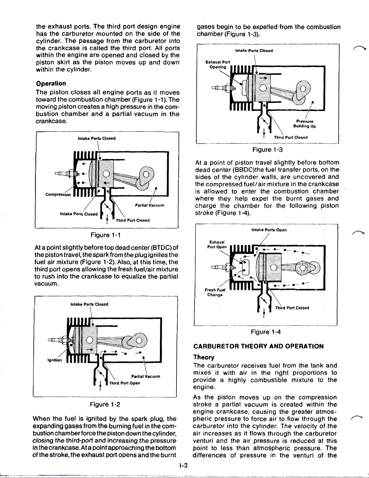
Operation
The piston closes all engine ports as it moves
toward the combustion chamber (Figure 1-1). The
moving piston creates a high pressure in the combustion chamber and a partial vacuum in the
crankcase.
Intake Ports Closed
Co
Figure 1-1
At
a point slightly before top dead center (BTDC) of
the piston travel, from the plug ignitesthe
fuel air mixture (Figure 1-2). Also, at this time, the
third port opens allowing the fresh fuel/air mixture
to rush into the crankcase to equalize the partial
vacuum.
Intake Ports Closed
\
Figure 1-2
When the fuel is ignited by the spark plug, the
expanding gases from the burning fuel in the combustion chamber force the piston down thecylinder,
closing the third-port and increasing the pressure
in the
crankcase. At
a point approaching the bottom
of the stroke, the exhaust port opens and the burnt
1-3
gases begin to be expelled from the combustion
chamber (Figure 1-3).
__-
--l_____m_
Intake Ports Closed
Exhaust Port
I
Third
Port Closed
~
Figure
1-3
At a point of piston travel slightly before bottom
dead center (BBDC)
the
fuel transfer ports, on the
sides of the cylinder walls, are uncovered and
the compressed fuel/air mixture in the crankcase
-is allowed to enter the combustion chamber
where they help expel the burnt gases and
charge the chamber for the following piston
stroke (Figure 1-4).
Intake Ports
Open
Exhaust
Change
__-__
Figure 1-4
CARBURETOR THEORY AND OPERATION
Theory
The carburetor receives fuel from the tank and
mixes
it
with air in the right proportions to
provide a highly combustible mixture to the
engine.
As the piston moves up on the compression
stroke a partial vacuum is created within the
engine crankcase, causing the greater atmos-
pheric pressure to force air to flow through the
carburetor into the cylinder. The velocity of the
air increases as it flows through the carburetor
venturi and the air pressure is reduced at this
point to less than atmospheric pressure. The
differences of pressure in the venturi of the
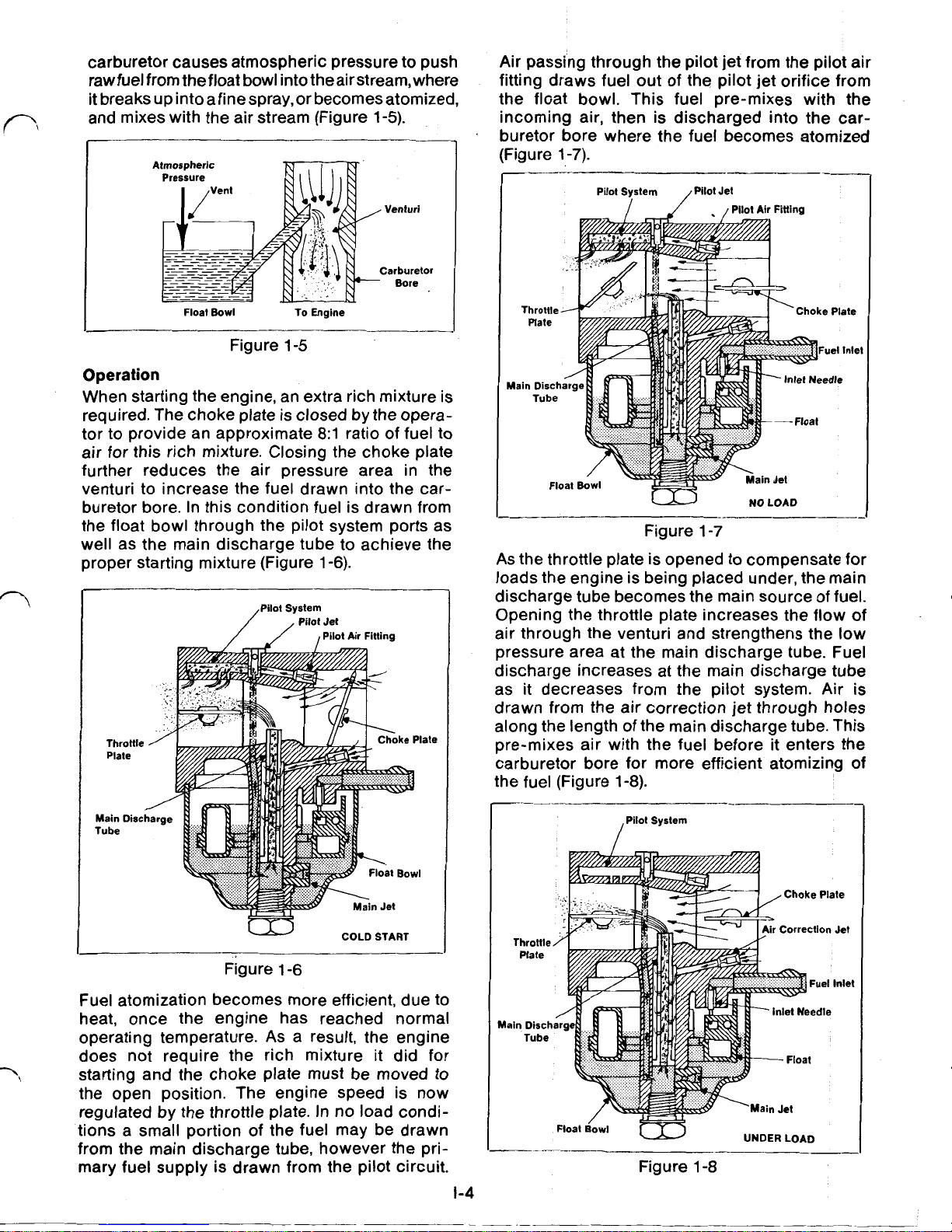
carburetor causes atmospheric pressure to push
rawfuel from the
float
bowl into theair
stream, where
it breaks up into a fine spray, or becomes atomized,
and mixes with the air stream (Figure
1-5).
Float
Bowl
To Engine
Figure
1-5
Operation
When starting the engine, an extra rich mixture is
required. The choke plate is closed by the opera-
tor to provide an approximate
8:1
ratio of fuel to
air for this rich mixture. Closing the choke plate
further reduces the air pressure area in the
venturi to increase the fuel drawn into the carburetor bore. In this condition fuel is drawn from
the float bowl through the pilot system ports as
well as the main discharge tube to achieve the
proper starting mixture (Figure
1-6).
Pilot
Jet
Pilot System
Pilot Air Fitting
COLD START
Figure
1-6
Fuel atomization becomes more efficient, due to
heat, once the engine has reached normal
operating temperature.
As
a result, the engine
does not require the rich mixture it did for
starting and the choke plate must be moved
to
the open position. The engine speed is now
regulated by the throttle plate. In no load conditions a small portion of the fuel may be drawn
from the main discharge tube, however the pri-
mary fuel supply is drawn from the pilot circuit.
1-4
Air passing through the pilot jet from the pilot air
fitting draws fuel out of the pilot jet orifice from
the float bowl. This fuel pre-mixes with the
incoming air, then is discharged into the carburetor bore where the fuel becomes atomized
(Figure
1-7).
NO
LOAD
Figure
1-7
As
the throttle plate is opened to compensate for
loads the engine is being placed under, the main
discharge tube becomes the main source of fuel.
Opening the throttle plate increases the flow of
air through the venturi and strengthens the low
pressure area at the main discharge tube. Fuel
discharge increases at the main discharge tube
as
it
decreases from the pilot system. Air
is
drawn from the air correction jet through holes
along the length of the main discharge tube. This
pre-mixes air with the fuel before it enters the
carburetor bore for more efficient atomizing of
:he fuel (Figure
1-8).
/pilot
System
Float
Bowl
UNDER LOAD
Figure
1-8
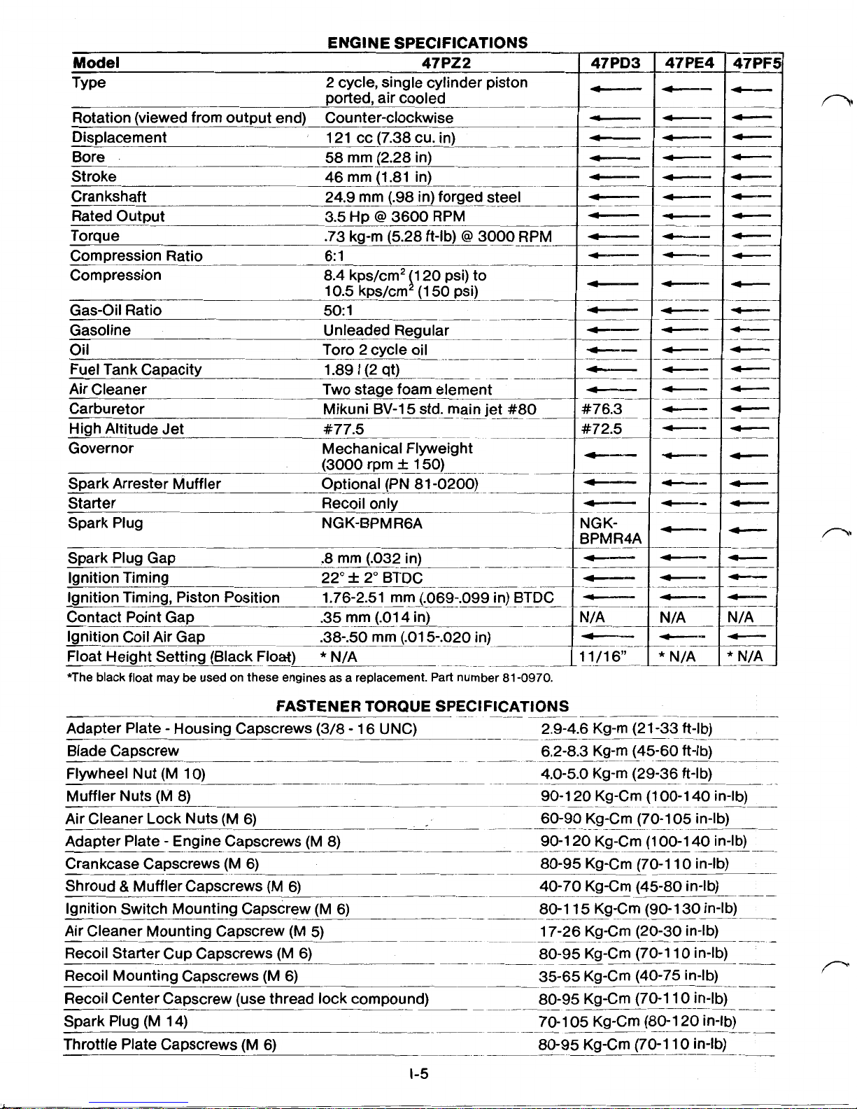
ENGINE SPECIFICATIONS
~---
Model
47P22
Type 2 cycle, single cylinder piston
ported, air cooled
Rotation (viewed from output end) Counter-clockwise
Displacement 121 cc (7.38 cu. in)
~-
Bore 58 mm (2.28 in)
Stroke 46 mm (1.81 in)
Crankshaft 24.9 mm (.98in) forged steel
Rated Output
3.5
Hp @ 3600 RPM
Torque .73 kg-m (5.28 ft-lb)
@
3000
RPM
Compression Ratio 6: 1
Compression
Gas-Oil Ratio
50:
1
Gasoline Unleaded Regular
TTO
Oil 2 cycle oil
Fuel Tank Capacity
Air Cleaner
Carburetor Mikuni
BV-15std.
main jet #80
High Altitude Jet
Governor Mechanical Flyweight
8.4kps/cm2 20 psi) to
10.5 kps/cm (1
50
psi)
1.89
I
(2 qt)
Two stage foam element
#77.5
--
-~
Spark Arrester Muffler Optional (PN 81-0200)
47PD3
#76.3
#72.5
Starter Recoil only
~-
Spark Plug NGK-BPMR6A
NGK-
BPMR4A
Ignition Timing 22" 2" BTDC
Ignition Timing, Piston Position 1.76-2.51mm (.069-.099in) BTDC
~-
Contact Point Gap .35 mm (.014in)
Ignition Coil Air Gap .38-.50 mm (.015-.020in)
Float Height Setting (Black Float)
*
N/A
11/16"
*The black float may be used on these engines as a replacement. Part number
81-0970.
.
N/A
*
N/A
FASTENER TORQUE SPECIFICATIONS
Adapter Plate Housing Capscrews (3/8-16UNC) 2.9-4.6 Kg-m (21
-33
ft-lb)
Blade Capscrew 6.2-8.3 Kg-m (45-60 ft-lb)
Flywheel Nut (M 10) 4.0-5.0 Kg-m (29-36 ft-lb)
Muffler Nuts (M 8)
90-120Kg-Cm (100-140 in-lb)
Air Cleaner Lock Nuts (M 6)
60-90 Kg-Cm (70-1
05
in-lb)
Adapter Plate Engine Capscrews (M 8)
90-120Kg-Cm (100-140in-lb)
Crankcase Capscrews (M 6) 80-95 Kg-Cm (70-1 10 in-lb)
Shroud
&
Muffler Capscrews (M 6)
40-70 Kg-Cm (45-80 in-lb)
Ignition Switch Mounting Capscrew (M 6) 80-1 15 Kg-Cm (90-1
30
in-lb)
Air Cleaner Mounting Capscrew (M
5)
17-26 Kg-Cm (20-30 in-lb)
Recoil Starter Cup Capscrews (M 6) 80-95 Kg-Cm (70-1 10 in-lb)
Recoil Mounting Capscrews (M 6) 35-65 Kg-Cm (40-75 in-lb)
Recoil Center Capscrew (use thread lock compound) 80-95 Kg-Cm (70-1 10 in-lb)
Spark Plug (M 14) 70-1
05
Kg-Cm (80-1 20 in-lb)
Throttle Plate Capscrews (M 6) 80-95 Kg-Cm (70-1 10 in-lb)
.-
.
-..-
__-
1-5
 Loading...