

Toro 4502, 8603, 4503, 8602 Service Manual
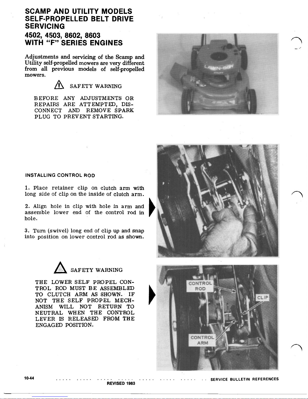
SCAMP AND UTILITY MODELS
SERVICING
4502, 4503, 8602, 8603
WITH
“F”
SERIES ENGINES
SELF-PROPELLED BELT DRIVE
Adjustments
and
servicing of the Scamp and
Utility self-propelled mowers are very different
from
all
previous models of self-propelled
mowers.
SAFETY WARNING
BEFORE
ANY
ADJUSTMENTS OR
REPAIRS ARE ATTEMPTED, DIS-
CONNECT
AND
REMOVE SPARK
PLUG TO PREVENT STARTING.
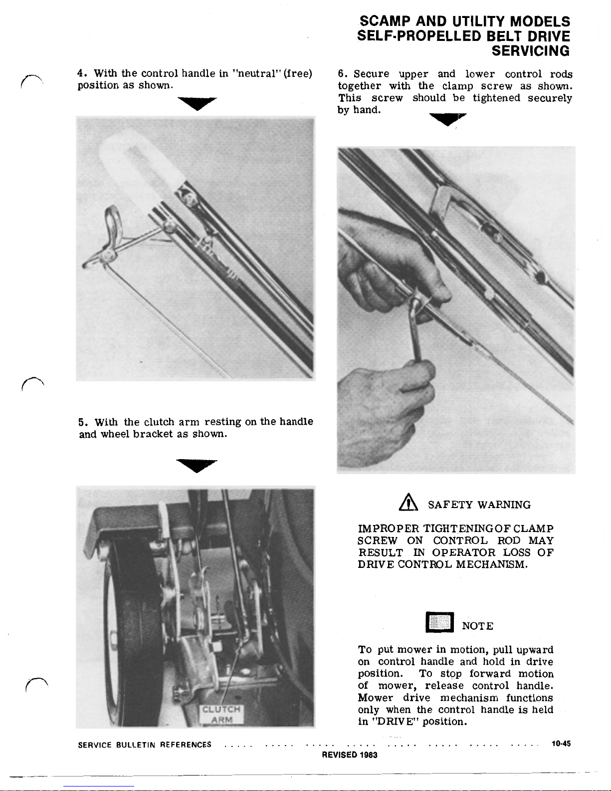
INSTALLING CONTROL
ROD
1.
Place retainer clip on clutch arm
with
long side
of
clip on the inside
of
clutch arm.
2.
Align
hole in
clip
with
hole in arm and
assemble lower end
of
the control
rod
in
hole.
3.
Turn (swivel) long end
of
clip up and snap
into position on lower control rod as shown.
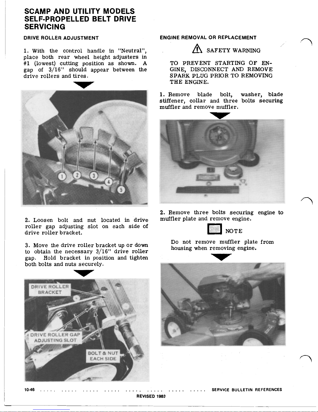
SAFETY WARNING
THE LOWER SELF PROPEL CONTROL ROD MUST
BE
ASSEMBLED
TO CLUTCH ARM
AS
SHOWN. IF
NOT THE SELF PROPEL MECHANISM WILL NOT RETURN TO
NEUTRAL WHEN THE CONTROL
LEVER IS RELEASED FROM THE
ENGAGED POSITION.
10-44
REVISED
1983
SERVICE BULLETIN REFERENCES
4.
With
the control handle in "neutral" (free)
position as shown.
SCAMP AND UTILITY MODELS
SERVICING
6.
Secure upper and lower control rods
together with the clamp screw as shown.
This screw should be tightened securely
SELF=PROPELLED BELT DRIVE
by hand.
5.
With
the clutch arm resting on the handle
and wheel bracket as shown.
SAFETY WARNING
IMPROPER TIGHT.ENING OF CLAMP
SCREW ON CONTROL ROD MAY
RESULT
IN
OPERATOR LOSS OF
DRIVE CONTROL MECHANISM.
NOTE
To
put mower in motion, pull upward
on control handle and hold in drive
position. To stop forward motion
of
mower, release control handle.
Mower drive mechanism functions
only when the control handle
is
held
in "DRIVE" position.
!
SCAMP AND UTILITY MODELS
SERVICING
SELF-PROPELLED BELT DRIVE
DRIVE ROLLER ADJUSTMENT
1.
With the control handle in "Neutral",
place both rear wheel height adjusters in
#1
(lowest) cutting position as shown.
A
gap of 3/16" should appear between the
drive rollers and tires.
2.
Loosen bolt and nut located in drive
roller gap adjusting slot on each side of
drive roller bracket.
3. Move the drive roller bracket up or down
to obtain the necessary 3/16'' drive roller
gap. Hold bracket
in
position and tighten
both bolts and nuts securely.
ENGINE REMOVAL
OR
REPLACEMENT
SAFETY WARNING
TO PREVENT STARTING OF ENGINE, DISCONNECT
AND
REMOVE
SPARK PLUG PRIOR TO REMOVING
THE ENGINE.
1.
Remove blade bolt, washer, blade
stiffener, collar and three bolts securing
muffler and remove muffler.
n
2.
Remove
three
bolts securing engine to
muffler plate and remove engine.
Do not remove muffler plate from
housing when removing engine.
10-46
SERVICE BULLETIN REFERENCES
REVISED
1983
 Loading...