

Toro 44751 Service Manual

Form No. 14204SL Rev B
ProPass® 200
Original Instructions (EN)

Revision History
Revision
Date
Description
--
2014
Initial Issue.
A
02/2018
Added revision history.
B
06/2020
Updated Electrical chapter.
©
reproduced by a third party without the express written consent of The Toro Company (and/or the appropriate affiliated company).
THE TORO COMPANY 2020
This document and all information contained herein is the sole property of The Toro Company (and/or its affiliated companies). No
intellectual property rights are granted by the delivery of this document or the disclosure of its content. This document shall not be

Reader Comments
The Toro Company Technical Assistance Center maintains a continuous effort to improve the quality
and usefulness of its publications. To do this effectively, we encourage user feedback.
Please comment on the completeness, accuracy, organization, usability, and readability of this manual
by an e-mail to servicemanuals@toro.com
or Mail to:
Technical Publication Manager, Commercial
The Toro Company
8111 Lyndale Avenue South
Bloomington, MN 55420-1196
Phone: +1 952-887-8495

NOTES _

Part No. 14204SL (Rev. B)
Service Manual
Preface
The purpose of this publication is to provide the service
technician with information for troubleshooting, testing
and repair of major systems and components on the
ProPass 200.
REFER TO THE OPERATOR’S MANUAL FOR OPERATING, MAINTENANCE AND ADJUSTMENT INSTRUCTIONS. For reference, insert a copy of the
Operator’s Manual and Parts Catalog for your machine
into Chapter 2 of this service manual. Additional copies
of the Operator’s Manual and Parts Catalog are available on the internet at www.Toro.com.
The Toro Company reserves the right to change product
specifications or this publication without notice.
ProPass
This safety symbol means DANGER, WARNING,
or CAUTION, PERSONAL SAFETY INSTRUCTION. When you see this symbol, carefully read
the instructions that follow. Failure to obey the
instructions may result in personal injury.
NOTE: A NOTE will give general information about the
correct operation, maintenance, service, testing or repair of the machine.
IMPORTANT: The IMPORTANT notice will give important instructions which must be followed to prevent damage to systems or components on the
machine.
200
R
E The Toro Company -- 2014, 2018, 2020

This page is intentionally blank.
ProPass 200

Table Of Contents
Chapter 1 -- Safety
General Safety Instructions 1 -- 2..................
Safety and Instruction Decals 1 -- 4................
Chapter 2 -- Product Records and Maintenance
Product Records 2 -- 1...........................
Maintenance 2 -- 1...............................
Equivalents and Conversions 2 -- 2................
Torque Specifications 2 -- 3.......................
Chapter 3 -- Hydraulic System
Specifications 3 -- 2..............................
General Information 3 -- 3........................
Hydraulic Schematics 3 -- 12......................
Hydraulic Flow Diagrams: Standard Hydraulic
Controls 3 -- 14...............................
Hydraulic Flow Diagrams: Electronic Hydraulic
Controls 3 -- 16...............................
Special Tools 3 -- 20.............................
Troubleshooting 3 -- 22...........................
Tes ti ng 3 - - 24...................................
Service and Repairs 3 -- 26.......................
EATON (CHAR--LYNN) S--SERIES GENERAL
PURPOSEMOTORS PARTS andREPAIRMANUAL
EATON (CHAR-- LYNN) R--SERIES GENERAL
PURPOSE GEROLER MOTOR REPAIR
INFORMATION
Chapter 4 -- Electrical System
General Information 4 -- 3........................
Electrical Schematics 4 -- 4.......................
Wire Harness Drawings 4 -- 10....................
Special Tools 4 -- 21.............................
Troubleshooting 4 -- 23...........................
Component Testing 4 -- 25........................
Chapter 5 -- Chassis
General Information 5 -- 3........................
Service and Repairs 5 -- 4........................
Chapter 6 -- Hydraulic Power Pack
Power Pack Engine Specifications 6 -- 2............
Power Pack Hydraulic Specifications 6 -- 3..........
General Information 6 -- 4........................
Electrical System Quick Checks 6 -- 5..............
Adjustments 6 -- 6...............................
Hydraulic Testing 6 -- 8...........................
Service and Repairs 6 -- 12.......................
EATON SERIES 26 GEAR PUMP PARTS and REPAIR
MANUAL
SafetyProduct Records
Hydraulic
Electrical
and Maintenance
System
System
ProPass 200
Chassis
Hydraulic
Power Pack

This page is intentionally blank.
ProPass 200

Chapter 1
Safety
Table of Contents
GENERAL SAFETY INSTRUCTIONS 2............
Before Operating 2............................
While Operating 2............................
Maintenance and Service 3....................
SAFETY AND INSTRUCTION DECALS 4..........
Safety
ProPass 200 Page 1 -- 1 Safety

General Safety Instructions
The ProPass 200 has been tested and certified by
TORO for compliance with existing safety standards
and specifications. Although hazard control and accident prevention partially are dependent upon the design
and configuration of the machine, these factors are also
dependent upon the awareness, concern and proper
training of the personnel involved in the operation, transport, maintenance and storage of the machine. Improper use or maintenance of the machine can result in injury
or death. To reduce the potential for injury or death, comply with the following safety instructions.
Before Operating
WARNING
To reduce the potential for injury or death,
comply with the following safety instructions.
1. Review and understand the contents of the Operator’s Manuals before starting and operating the machine. Become familiar with the controls and know how
to stop the machine and engine quickly. Additional copies of the Operator’s Manual are available on the internet at www.Toro.com.
2. Keep all shields, safety devices and decals in place.
If a shield, safety device or decal is defective, illegible or
damaged, repair or replace it before operating the machine. Also tighten any loose nuts, bolts or screws to ensure machine is in safe operating condition.
While Operating
1. The operator should be in the operators position
when operating the tow vehicle and ProPass machine.
Stay away from the ProPass when the floor and rear option (twin spinner or side conveyor) system are engaged.
2. Do not run engine that powers the ProPass in a confined area without adequate ventilation. Exhaust fumes
are hazardous and could possibly be deadly.
3. Make sure that the tow vehicle is carefully selected
to assure the best performance and safe operation of
the ProPass machine.
4. Make sure that the operator is familiar with tow vehicle and ProPass operation.
5. Make sure that ProPass is properly secured to tow
vehicle before operating.
7. If ProPass is equipped with a wireless controller, always be in line of sight with the machine when operating,
adjusting or programming the wireless controller.
8. Make sure that the ProPass load is distributing
evenly to prevent shifting of contents.
9. Before leaving the operator’s position of the tow
vehicle:
3. Do not touch engine, muffler or exhaust pipe while
engine is running or soon after it is stopped. These areas
could be hot enough to cause burns.
4. If abnormal vibration is detected, stop operation of
the ProPass immediately and determine source of
vibration. Correct problems before resuming the use of
the machine.
5. While operating, the ProPass may exceed noise levels of 85dB(A) at the operator position. Hearing protection is recommended for prolonged exposure to reduce
the potential of permanent hearing damage.
6. Do not leave the ProPass unattended when it is running.
A. Stop on level ground.
B. Make sure that ProPass floor is stopped and then
disengage spinner system.
C. Ensure that tow vehicle traction lever is in neutral,
set parking brake, stop engine and remove key from
ignition switch.
10.Before disconnecting the ProPass tow behind
chassis from the tow vehicle, park on level surface, ensure that the front tongue jack is in the support position
and chock wheels.
ProPass 200Page 1 -- 2Safety

Maintenance and Service
1. The Operator’s Manual provides information regarding the operation, general maintenance and maintenance intervals for your ProPass machine. Refer to this
publication for additional information when servicing the
machine.
2. Before servicing or making adjustments, position
ProPass machine on a level surface. Engage tow vehicle parking brake, stop engine and remove key from
the ignition switch. If ProPass is equipped with wireless
controller, power off wireless controller. On ProPass
mounted to a tow behind chassis, chock wheels to prevent it from moving.
3. If equipped, press the E--stop button to disable the
ProPass electrical system before working on the machine.Pullthebuttonoutwhenmachineistobereturned
to use.
4. Make sure machine is in safe operating condition by
keeping all nuts, bolts and screws tight.
5. Never store the machine or fuel container inside
where there is an open flame, such as near a water heater or furnace.
6. Make sure all hydraulic line connectors are tight and
all hydraulic hoses and lines are in good condition before applying pressure to the hydraulic system.
7. Keep body and hands away from pin hole leaks in hydraulic lines that eject high pressure hydraulic fluid. Use
cardboard or paper to find hydraulic leaks. Hydraulic
fluid escaping under pressure can penetrate skin and
cause injury. Hydraulic fluid accidentally injected into the
skin must be surgically removed within a few hours by
a doctor familiar with this form of injury or gangrene may
result.
8. Before disconnecting any hydraulic component or
performing any work on the hydraulic system, all pressure in system must be relieved. See Relieving Hydraulic System Pressure in the General Information section
of Chapter 3 -- Hydraulic System.
Safety
9. Make sure that electrical power harness from tow vehicle is disconnected before working on the machine’s
electrical system.
10.If major repairs are ever needed or assistance is desired, contact your Authorized Toro Distributor.
11. At the time of manufacture, the machine conformed
to all applicable safety standards. To assure optimum
performance and continued safety certification of the
machine, use genuine Toro replacement parts and ac cessories. Replacement parts and accessories made
by other manufacturers may result in non-conformance
with the safety standards, and the warranty may be
voided.
12.When changing tires or performing other service on
your ProPass machine, use correct hoists and jacks.
Make sure machine is parked on a solid level surface
such as a concrete floor with the hopper empty. Always
chock or block wheels. Use appropriate stands to support the raised machine. If the machine is not properly
supported, the machine may move or fall, which may result in personal injury.
ProPass 200 Page 1 -- 3 Safety

Safety and Instruction Decals
Numerous safety and instruction decals are affixed to
the ProPass 200. If any decal becomes illegible or damaged, install a new decal. Decal part numbers are listed
in your Parts Catalog.
ProPass 200Page 1 -- 4Safety

Product Records and Maintenance
Table of Contents
PRODUCT RECORDS 1.........................
MAINTENANCE 1..............................
EQUIVALENTS AND CONVERSIONS 2...........
Decimal and Millimeter Equivalents 2............
U.S. to Metric Conversions 2...................
TORQUE SPECIFICATIONS 3...................
Fastener Identification 3.......................
Using a Torque Wrench with an Offset Wrench 3..
Standard Torque for Dry, Zinc Plated and
Steel Fasteners (Inch Series) 4...............
Standard Torque for Dry, Zinc Plated and
Steel Fasteners (Metric Fasteners) 5..........
Other Torque Specifications 6..................
Conversion Factors 6.........................
Chapter 2
and Maintenance
Product Records
Product Records
Insert Operator’s Manuals and Parts Catalog for your
ProPass at the end of this chapter. Additionally, insert
Installation Instructions, Operator’s Manuals and Parts
Catalogs for any accessories that have been installed
on your ProPass at the end of this section.
Maintenance
Maintenance procedures and recommended service intervals for your ProPass are covered in the Operator’s
Manual. Refer to this publications when performing regular equipment maintenance. Several maintenance procedures have break--in intervals identified in the
Operator’s Manuals. If machine is equipped with the hydraulic power pack, refer to the Engine Owner’s Manual
for additional engine specific maintenance procedures.
ProPass 200 Page 2 -- 1 Product Records and Maintenance
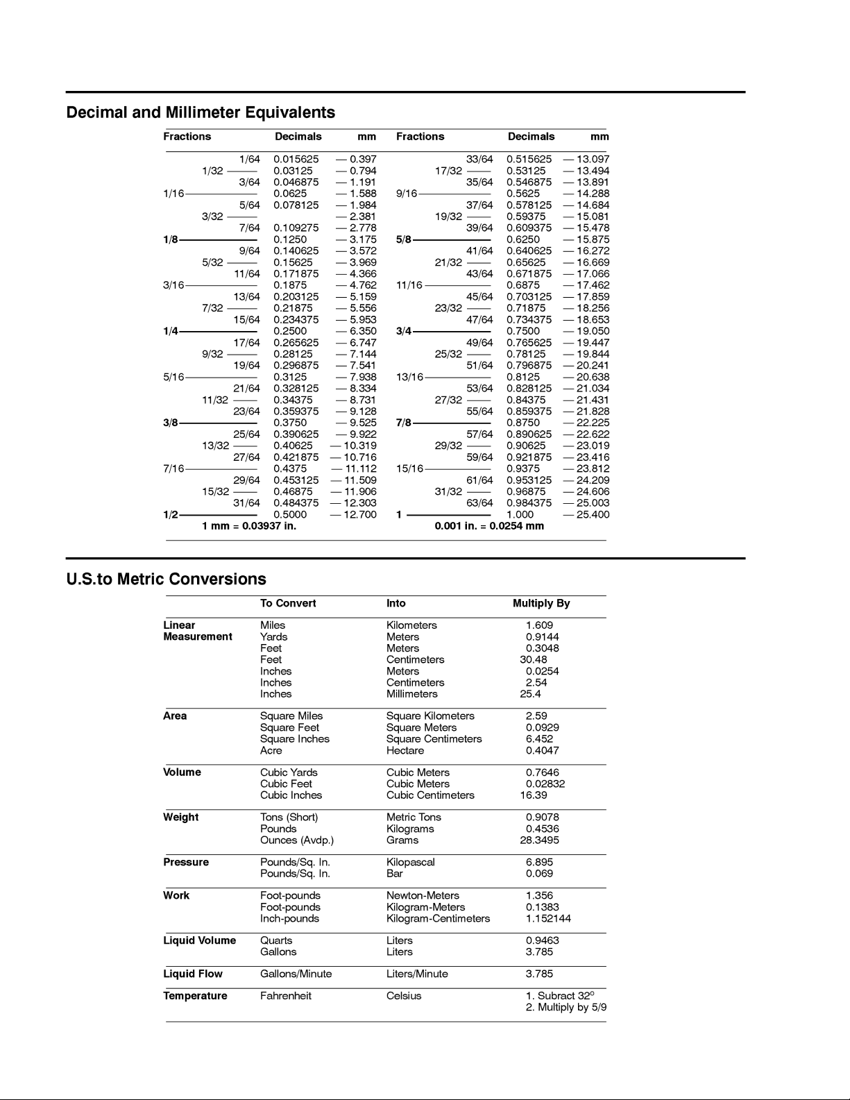
Equivalents and Conversions
0.09375
ProPass 200Page 2 -- 2Product Records and Maintenance

Torque Specifications
Recommended fastener torque values are listed in the
following tables. For critical applications, as determined
by Toro, either the recommended torque or a torque that
is unique to the application is clearly identified and specified in this Service Manual.
These Torque Specifications for the installation and
tightening of fasteners shall apply to all fasteners which
do not have a specific requirement identified in this Service Manual. The following factors shall be considered
when applying torque: cleanliness of the fastener, use
of a thread sealant (e.g. Loctite), degree of lubrication
on the fastener, presence of a prevailing torque feature
(e.g. Nylock nut), hardness of the surface underneath
the fastener’s head or similar condition which affects the
installation.
Fastener Identification
As noted in the following tables, torque values should be
reduced by 25% for lubricated fasteners to achieve
the similar stress as a dry fastener. Torque values may
also have to be reduced when the fastener is threaded
into aluminum or brass. The specific torque value
should be determined based on the aluminum or brass
material strength, fastener size, length of thread engagement, etc.
The standard method of verifying torque shall be performed by marking a line on the fastener (head or nut)
and mating part, then back off fastener 1/4 of a turn.
Measure the torque required to tighten the fastener until
thelinesmatchup.
and Maintenance
Product Records
Grade 1 Grade 5 Grade 8
Inch Series Bolts and Screws
Figure 1
Using a Torque Wrench with an Offset Wrench
Use of an offset wrench (e.g. crowfoot wrench) will affect
torque wrench calibration due to the effective change of
torque wrench length. When using a torque wrench with
an offset wrench, multiply the listed torque recommendation by the calculated torque conversion factor (Fig.
3) to determine proper tightening torque. Tightening
torque when using a torque wrench with an offset
wrench will be lower than the listed torque recommendation.
Example: The measured effective length of the torque
wrench (distance from the center of the handle to the
center of the square drive) is 18”.
The measured effective length of the torque wrench with
the offset wrench installed (distance from the center of
the handle to the center of the offset wrench) is 19”.
Class 8.8 Class 10.9
Metric Bolts and Screws
Figure 2
If the listed torque recommendation for a fastener is
from 76 to 94 ft--lb, the proper torque when using this
torque wrench with an offset wrench would be from 72
to 89 ft--lb.
(effective length of
torque wrench)
A
B
(effective length of torque
wrench + offset wrench)
TORQUE CONVERSION FACTOR = A / B
Torque wrenchOffset wrench
The calculated torque conversion factor for this torque
wrench with this offset wrench would be 18 / 19 = 0.947.
ProPass 200 Page 2 -- 3 Product Records and Maintenance
Figure 3

Standard Torque for Dry, Zinc Plated and Steel Fasteners (Inch Series)
Grade 1, 5 &
Thread Size
#6--32UNC
#6--40UNF 17 + 2 192 + 23 25 + 3 282 + 34
#8--32UNC
#8--36UNF 31 + 4 350 + 45 43 + 5 486 + 56
#10--24UNC
#10--32UNF 48 + 5 542 + 56 68 + 7 768 + 79
1/4 -- 20 UNC 48 + 7 53 + 7 599 + 79 100 + 10 1130 + 11 3 140 + 15 1582 + 169
1/4 -- 28 UNF 53 + 7 65 + 10 734 + 11 3 11 5 + 12 1299 + 136 160 + 17 1808 + 192
5/16 -- 18 UNC 115 + 15 105 + 15 1186 + 169 200 + 25 2260 + 282 300 + 30 3390 + 339
5/16 -- 24 UNF 138 + 17 128 + 17 1446 + 192 225 + 25 2542 + 282 325 + 33 3672 + 373
3/8 -- 16 UNC 16 + 2 16 + 2 22 + 3 30 + 3 41 + 4 43 + 5 58 + 7
8withThin
Height Nuts
in--lb in--lb N--cm in --lb N--cm in --lb N--cm
10 + 2 13 + 2 147 + 23
13 + 2 25 + 5 282 + 30
18 + 2 30 + 5 339 + 56
ft--lb ft--lb N--m ft--lb N--m ft--lb N--m
SAE Grade 1 Bolts, Screws, Studs &
Sems with Regular Height Nuts
(SAE J995 Grade 2 or Stronger Nuts)
SAE Grade 5 Bolts, Screws, Studs &
Sems with Regular Height Nuts
(SAE J995 Grade 2 or Stronger Nuts)
15 + 2 169 + 23 23 + 3 262 + 34
29 + 3 328 + 34 41 + 5 463 + 56
42 + 5 475 + 56 60 + 6 678 + 68
SAE Grade 8 Bolts, Screws, Studs &
Sems with Regular Height Nuts
(SAE J995 Grade 5 or Stronger Nuts)
3/8 -- 24 UNF 17 + 2 18 + 2 24 + 3 35 + 4 47 + 5 50 + 6 68 + 8
7/16 -- 14 UNC 27 + 3 27 + 3 37 + 4 50 + 5 68 + 7 70 + 7 95 + 9
7/16 -- 20 UNF 29 + 3 29 + 3 39 + 4 55 + 6 75 + 8 77 + 8 104 + 11
1/2 -- 13 UNC 30 + 3 48 + 7 65 + 9 75 + 8 102 + 11 105 + 11 142 + 15
1/2 -- 20 UNF 32 + 4 53 + 7 72 + 9 85 + 9 115 + 12 120 + 12 163 + 16
5/8 -- 11 UNC 65 + 10 88 + 12 11 9 + 16 150 + 15 203 + 20 210 + 21 285 + 28
5/8 -- 18 UNF 75 + 10 95 + 15 129 + 20 170 + 18 230 + 24 240 + 24 325 + 33
3/4 -- 10 UNC 93 + 12 140 + 20 190 + 27 265 + 27 359 + 37 375 + 38 508 + 52
3/4 -- 16 UNF 115 + 15 165 + 25 224 + 34 300 + 30 407 + 41 420 + 43 569 + 58
7/8 -- 9 UNC 140 + 20 225 + 25 305 + 34 430 + 45 583 + 61 600 + 60 813 + 81
7/8 -- 14 UNF 155 + 25 260 + 30 353 + 41 475 + 48 644 + 65 667 + 66 904 + 89
NOTE: Reduce torque values listed in the table above
by 25% for lubricated fasteners. Lubricated fasteners
are defined as threads coated with a lubricant such as
engine oil or thread sealant such as Loctite.
NOTE: The nominal torque values listed above for
Grade 5 and 8 fasteners are based on 75% of the minimum proof load specified in SAE J429. The tolerance is
approximately +
10% of the nominal torque value. Thin
height nuts include jam nuts.
NOTE: Torque values may have to be reduced when
installing fasteners into threaded aluminum or brass.
The specific torque value should be determined based
on the fastener size, the aluminum or base material
strength, length of thread engagement, etc.
ProPass 200Page 2 -- 4Product Records and Maintenance

Standard Torque for Dry, Zinc Plated and Steel Fasteners (Metric Series)
Class 8.8 Bolts, Screws and Studs with
Thread Size
M5 X 0.8 57 + 6in--lb 644 + 68 N--cm 78 + 8in--lb 881 + 90 N --cm
M6 X 1.0 96 + 10 in--lb 1085 + 113 N- -cm 133 + 14 in--lb 1503 + 158 N--cm
M8 X 1.25 19 + 2ft--lb 26 + 3N--m 28 + 3ft--lb 38 + 4N--m
M10 X 1.5 38 + 4ft--lb 52 + 5N--m 54 + 6ft--lb 73 + 8N--m
M12 X 1.75 66 + 7ft--lb 90 + 10 N--m 93 + 10 ft--lb 126 + 14 N--m
M16 X 2.0 166 + 17 ft--lb 225 + 23 N--m 229 + 23 ft--lb 310 + 31 N--m
M20 X 2.5 325 + 33 ft--lb 440 + 45 N --m 450 + 46 ft--lb 610 + 62 N--m
NOTE: Reduce torque values listed in the table above
by 25% for lubricated fasteners. Lubricated fasteners
are defined as threads coated with a lubricant such as
engine oil or thread sealant such as Loctite.
NOTE: Torque values may have to be reduced when
installing fasteners into threaded aluminum or brass.
The specific torque value should be determined based
on the fastener size, the aluminum or base material
strength, length of thread engagement, etc.
Regular Height Nuts
(Class 8 or Stronger Nuts)
NOTE: The nominal torque values listed above are
based on 75% of the minimum proof load specified in
SAE J1199. The tolerance is approximately +
nominal torque value.
Class 10.9 Bolts, Screws and Studs with
Regular Height Nuts
(Class 10 or Stronger Nuts)
10% of the
and Maintenance
Product Records
ProPass 200 Page 2 -- 5 Product Records and Maintenance

Other Torque Specifications
SAE Grade 8 Steel Set Screws
Recommended Torque
Thread Size
Square Head Hex Socket
1/4 -- 20 UNC 140 + 20 in--lb 73 + 12 in--lb
5/16 -- 18 UNC 215 + 35 in--lb 145 + 20 in--lb
3/8 -- 16 UNC 35 + 10 ft--lb 18 + 3ft--lb
1/2 -- 13 UNC 75 + 15 ft--lb 50 + 10 ft--lb
Thread Cutting Screws
(Zinc Plated Steel)
Type 1, Type 23 or Type F
Thread Size Baseline Torque*
No. 6 -- 32 UNC 20 + 5in--lb
Wheel Bolts and Lug Nuts
Thread Size
7/16 -- 20 UNF
Grade 5
1/2 -- 20 UNF
Grade 5
M12 X 1.25
Class 8.8
M12 X 1.5
Class 8.8
** For steel wheels and non--lubricated fasteners.
Thread Cutting Screws
(Zinc Plated Steel)
Thread
Size
No. 6 18 20 20 + 5in--lb
Threads per Inch
Typ e A Typ e B
Recommended Torque**
65 + 10 ft--lb 88 + 14 N--m
80 + 10 ft--lb 108 + 14 N--m
80 + 10 ft--lb 108 + 14 N--m
80 + 10 ft--lb 108 + 14 N--m
Baseline Torque*
No. 8 -- 32 UNC 30 + 5in--lb
No. 10 -- 24 UNC 38 + 7in--lb
1/4 -- 20 UNC 85 + 15 in--lb
5/16 -- 18 UNC 110 + 20 in--lb
3/8 -- 16 UNC 200 + 100 in--lb
Conversion Factors
in--lb X 11.2985 = N --cm N--cm X 0.08851 = in--lb
ft--lb X 1.3558 = N--m N--m X 0.7376 = ft-- lb
No. 8 15 18 30 + 5in--lb
No. 10 12 16 38 + 7in--lb
No. 12 11 14 85 + 15 in--lb
* Hole size, material strength, material thickness and fin-
ish must be considered when determining specific
torque values. All torque values are based on non--lubri-
cated fasteners.
ProPass 200Page 2 -- 6Product Records and Maintenance

Table of Contents
Chapter 3
Hydraulic System
SPECIFICATIONS 2............................
GENERAL INFORMATION 3.....................
Operator’s Manual 3..........................
ProPass Hydraulic Supply 3....................
Hydraulic Hose Kit (Tow Vehicle to ProPass) 3....
Machine Hydraulic Control 4...................
Rear Option 5................................
Relieving Hydraulic System Pressure 5..........
Hydraulic Hoses 6............................
Hydraulic Hose and Tube Installation (O--Ring
Face Seal Fittings) 6........................
Hydraulic Hose and Tube Installation (JIC Flared
Fittings) 8..................................
Hydraulic O--Ring Face Seal (ORFS) Fitting
Installation 9................................
Hydraulic JIC Flared Fitting Installation 11.........
HYDRAULIC SCHEMATICS 12...................
Standard Hydraulic Controls 12.................
Electronic Hydraulic Controls 13................
HYDRAULIC FLOW DIAGRAMS: STANDARD
HYDRAULIC CONTROLS 14...................
Rear Option Circuit (Twin Spinner or Conveyor) 14
Floor Circuit 14...............................
HYDRAULIC FLOW DIAGRAMS: ELECTRONIC
HYDRAULIC CONTROLS 16...................
Rear Option Circuits (Twin Spinner or Conveyor) 16
Floor Circuit 18...............................
SPECIAL TOOLS 20............................
TROUBLESHOOTING 22........................
TESTING 24...................................
SERVICE AND REPAIRS 26.....................
General Precautions for Removing and
Installing Hydraulic System Components 26....
Check Hydraulic Lines and Hoses 27............
Hydraulic Control (Machines with Standard
Hydraulic Controls) 28.......................
Control Valve Service (Machines with Standard
Hydraulic Controls) 30.......................
Solenoid Valve Assembly (Machines with Standard
Hydraulic Controls) 31.......................
Hydraulic Control (Machines with Electronic
Hydraulic Controls) 32.......................
Hydraulic Control Manifold (Machines with
Electronic Hydraulic Controls) 34..............
Floor Motor 38................................
Floor Motor Service 40........................
Twin Spinner Motors 42........................
Conveyor Motor 44............................
Rear Option Motor Service 46..................
EATON (CHAR--LYNN) S--SERIES GENERAL
PURPOSE MOTORS PARTS and REPAIR MANUAL
EATON (CHAR--LYNN) R--SERIES GENERAL
PURPOSE GEROLER MOTOR REPAIR
INFORMATION
System
Hydraulic
ProPass 200 Page 3 -- 1 Hydraulic System

Specifications
Item Description
Tow Vehicle Hydraulic Supply
Minimum Supply 6 US Gal/Min (23 L/Min) @ 2000 PSI (138 Bar)
Maximum Supply 10 US Gal/Min (38 L/Min) @ 2800 PSI (190 Bar)
Floor Motor Eaton fixed displacement geroler motor
Displacement (per revolution) 22.7 in
Twin Spinner Motors (Rear Option) Eaton fixed displacement geroler motor
Displacement (per revolution) 1.8 in
Conveyor Motor (Rear Option) Eaton fixed displacement geroler motor
Displacement (per revolution) 1.8 in
3
(371 cc)
3
3
NOTE: If tow vehicle provides hydraulic supply,use tow
vehicle hydraulic specifications for information regarding hydraulic flow and relief pressure to the ProPass. If
hydraulic power pack provides hydraulic supply, see
Chapter 6 -- Hydraulic Power Pack Assembly for information regarding hydraulic circuit flow and relief pressure
specifications.
(29 cc)
(29 cc)
ProPass 200Page 3 -- 2Hydraulic System

General Information
Operator’s Manual
The Operator ’s Manual provides information regarding
the operation, general maintenance and maintenance
intervals for your ProPass machine. Refer to that publication for additional information when servicing the machine.
ProPass Hydraulic Supply
Hydraulic supply for the ProPass machine is either
provided by the tow vehicle or a hydraulic power pack.
If tow vehicle provides hydraulic supply, use tow vehicle
hydraulic specifications for information regarding hydraulic flow and relief pressure to the ProPass. If hydraulic power pack provides hydraulic supply, see
Chapter 6 -- Hydraulic Power Pack Assembly for information regarding hydraulic circuit flow and relief pressure
specifications.
NOTE: See Specifications in this chapter for tow
vehicle hydraulic supply recommendations.
System
Hydraulic
Hydraulic Hose Kit (Tow Vehicle to ProPass)
The hydraulic hose kit used when a ProPass receives its
hydraulic supply from a tow vehicle includes a check
valve in the return hose assembly (item 6 in Figure 1).
If the check valve is removed from the return hose, make
sure that the arrow on the check valve is directed toward
the tow vehicle. Also, when connecting the hydraulic
hoses to the tow vehicle, use the check valve to identify
the return hose for correct installation.
4
3
4
7
6
5
Figure 1
1. Hydraulic hose (supply)
2. Hydraulic hose (return)
3. Dust cap
4. Male coupler
3
5. O--ring
6. Check valve
7. O--ring
1
2
TOW VEHICLE
ProPass 200 Page 3 -- 3 Hydraulic System

Machine Hydraulic Control
ProPass 200 machines use either standard hydraulic
controls or electronic hydraulic controls to allow the operator to change machine settings.
Standard Hydraulic Controls
2
Machines with standard hydraulic controls include
manual hydraulic controls on the front of the ProPass
hopper to adjust hydraulic flow to the floor and rear option (twin spinner or conveyor) motors (Fig. 2). A
pendant electrical control allows the operator to energize the floor and rear option motors from the operator
position of the tow vehicle.
Electronic Hydraulic Controls
Machines with electronic hydraulic controls include a
wireless remote to electrically adjust hydraulic flow to
the floor and rear option (twin spinner or conveyor) motors (Fig. 3). The remote allows initial adjustment of the
floor and rear option motors as well as making adjustments possible while the machine is operating. An
E--Stopbuttononthemachinedisablestheelectrical
system to prevent unexpected machine operation.
If there should be a problem with the wireless remote,
ProPass machines with electronic controls have manual
override adjustments on the driver side of the hydraulic
system that will allow continued operation (Fig. 4). A
control knob is used to adjust floor speed and a flat blade
screwdriver can be used to adjust the rear option speed.
1
1. Floor control
2. Rear option control
2
3
Figure 2
3. Pendant harness
1
3
4
Figure 3
1. Wireless remote
2. E--Stop button
3. Power lead harness
4. Optional power pack
1
2
Figure 4
1. Control knob 2. Screwdriver slot
ProPass 200Page 3 -- 4Hydraulic System

Rear Option
The ProPass includes the twin spinner that is used for
topdressing (Fig. 5). The twin spinner uses two (2) hydraulic motors for operation. The cross conveyor and
swivel is available as an option for delivery of material
from the ProPass hopper (Fig. 6). The conveyor uses
one (1) hydraulic motor for operation.
The ProPass hydraulic system is used to operate either
of these rear options.
Figure 5
System
Hydraulic
Figure 6
Relieving Hydraulic System Pressure
Make sure that the ProPass has electrical power and
CAUTION
Before disconnecting any hydraulic components, operate all hydraulic controls to relieve
system pressure and avoid injury from pressurized hydraulic oil.
Before disconnecting or performing any work on the
ProPass hydraulic system, all pressure in the hydraulic
system must be relieved. Position machine on a level
surface. Turn tow vehicle key switch to OFF and allow
engine to stop. If ProPass is equipped with hydraulic
power pack, make sure that power pack engine is turned
off.
ProPass 200 Page 3 -- 5 Hydraulic System
that controls are operational. With the tow vehicle engine not running, use the pendant control or wireless
controller to energize the hydraulic solenoids for the
floor and rear option (twin spinner or conveyor) motors.
After both hydraulic functions have been energized, turn
tow vehicle key switch OFF and remove key from ignition switch.

Hydraulic Hoses
Hydraulic hoses are subject to extreme conditions such
as pressure differentials during operation and exposure
to weather, sun, chemicals, very warm storage conditions or mishandling during operation and maintenance.
These conditions can cause hose damage and deterioration. Some hoses are more susceptible to these
conditions than others. Inspect all machine hydraulic
hoses frequently for signs of deterioration or damage:
WARNING
Before disconnecting or performing any work on
hydraulic system, relieve all pressure in system
(see Relieving Hydraulic System Pressure in this
section).
Hard, cracked, cut, abraded, charred, leaking or
otherwise damaged hose.
Kinked, crushed, flattened or twisted hose.
Blistered, soft, degraded or loose hose cover.
Cracked, damaged or badly corroded hose fittings.
When replacing a hydraulic hose, be sure that the hose
is straight (not twisted) before tightening the fittings.
This can be done by observing the imprint (layline) on
the hose. Use two (2) wrenches; hold the hose straight
with one wrench and tighten the hose swivel nut onto the
fitting with the second wrench (see Hydraulic Hose and
Tube Installation in this section). If the hose has an elbow at one end, tighten the swivel nut on that end before
tightening the nut on the straight end of the hose.
For additional hydraulic hose information, refer to Toro
Service Training Book, Hydraulic Hose Servicing (Part
Number 94813SL).
Keep body and hands away from pin hole leaks or
nozzles that eject hydraulic fluid under high
pressure. Use paper or cardboard, not hands, to
search for leaks. Hydraulic fluid escaping under
pressure can have sufficient force to penetrate
the skin and cause serious injury. If fluid is injected into the skin, it must be surgically removed within a few hours by a doctor familiar
with this type of injury. Gangrene may result from
such an injury.
Hydraulic Hose and Tube Installation (O--Ring Face Seal Fittings)
NOTE: ProPass machines with serial numbers above
310001000 use O--ring face seal fittings (Fig. 7). Use the
following information when installing hydraulic hoses
and tubes to O--ring face seal fittings.
1. Make sure threads and sealing surfaces of the hose/
tube and the fitting are free of burrs, nicks, scratches or
any foreign material.
2. As a preventative measure against leakage, it is recommended that the face seal O--ring be replaced any
time the connection is opened. Make sure the O--ring is
installed and properly seated in the fitting groove. Lightly
lubricate the O--ring with clean hydraulic oil.
3. Place the hose/tube against the fitting body so that
theflatfaceofthehose/tubesleevefullycontactstheO-ring in the fitting.
1
1. Hydraulic hose/tube
2. Swivel nut
2
Figure 7
3
3. O--ring
4. Fitting body
ProPass 200Page 3 -- 6Hydraulic System
4

4. Thread the hose/tube swivel nut onto the fitting by
hand. While holding the hose/tube with a wrench, use a
torque wrench to tighten the swivel nut to the recommended installation torque shown in Figure 9. This tightening process will require the use of an offset wrench
(e.g. crowfoot wrench). Use of an offset wrench will affect torque wrench calibration due to the effective length
change of the torque wrench. Tightening torque when
using a torque wrench with an offset wrench will be lower
than the listed installation torque (see Using a Torque
Wrench with an Offset Wrench in the Torque Specifications section of Chapter 2 -- Product Records and Maintenance).
C. Useasecondwrenchtotightenthenuttothecorrect Flats From Wrench Resistance (F.F.W.R.). The
markings on the nut and fitting body will verify that the
connection has been properly tightened.
Size F.F.W.R.
4 (1/4 in. nominal hose or tubing) 1/2 to 3/4
6 (3/8 in.) 1/2 to 3/4
8 (1/2 in.) 1/2 to 3/4
10 (5/8 in.) 1/2 to 3/4
12 (3/4 in.) 1/3 to 1/2
16 (1 in.) 1/3 to 1/2
5. If a torque wrench is not available or if space at the
swivel nut prevents use of a torque wrench, an alternate
Mark Nut
and Fitting
Body
Final
Position
method of assembly is the Flats From Wrench Resistance (F.F.W.R.) method (Fig. 8).
A. Using a wrench, tighten the swivel nut onto the fitting until light wrench resistance is reached (approximately 30 in--lb).
B. Mark the swivel nut and fitting body. Hold the
AT WRENCH RESISTANCE
Extend Line
Figure 8
hose/tube with a wrench to prevent it from turning.
Fitting Dash Size Hose/Tube Side Thread Size Installation Torque
4 9/16 -- 18 18to22ft--lb(25to29N--m)
6 11/16 - - 16 27to33ft--lb(37to44N--m)
8 13/16 -- 16 37to47ft--lb(51to63N--m)
10 1--14 60 to 74 ft--lb (82 to 100 N--m)
12 13/16--12 85to105ft--lb(116to142N--m)
16 17/16--12 110to136ft--lb(150to184N--m)
Initial
Position
AFTER TIGHTENING
System
Hydraulic
20 1 11/16 -- 12 140 to 172 ft--lb (190 to 233 N--m)
Figure 9
ProPass 200 Page 3 -- 7 Hydraulic System

Hydraulic Hose and Tube Installation (JIC Flared Fittings)
NOTE: ProPass machines with serial numbers below
310001000 use JIC flared fittings (Fig. 10). Use the following information when installing hydraulic hoses and
tubes to JIC flared fittings.
1. Make sure threads and sealing surfaces of the hose/
tube and the fitting are free of burrs, nicks, scratches or
any foreign material.
2. Thread hose/tube swivel nut onto fitting by hand.
While holding the hose/tube with a wrench, use a torque
wrench to tighten swivel nut to the recommended installation torque shown in Figure 12. If fitting is non--ferrous
material (e.g. brass), use 50% of listed torque values.
This tightening process will require the use of an offset
wrench (e.g. crowfoot wrench) that will affect torque
wrench calibration due to the effective length change of
the torque wrench. Tightening torque when using a
torque wrench with an offset wrench will be lower than
the listed installation torque (see Using a Torque
Wrench with an Offset Wrench in the Torque Specifications section of Chapter 2 -- Product Records and Maintenance).
3. If a torque wrench is not available or if space at the
swivel nut prevents use of a torque wrench, an alternate
method of assembly is the Flats From Wrench Resistance (F.F.W.R.) method (Fig. 11).
Si z e F.F. W. R .
4 (1/4 in. nominal hose or tubing) 1/2 to 3/4
6 (3/8 in.) 1/2 to 3/4
8 (1/2 in.) 1/2 to 3/4
10 (5/8 in.) 1/2 to 3/4
12 (3/4 in.) 1/3 to 1/2
16 (1 in.) 1/3 to 1/2
JIC FLARED FITTING
(ADJUSTABLE TYPE SHOWN)
Figure 10
Mark Nut
and Fitting
Body
Final
Position
A. Using a wrench, tighten the swivel nut onto the fitting until light wrench resistance is reached (approxi-
Extend Line
mately 30 in--lb).
AT WRENCH RESISTANCE
AFTER TIGHTENING
B. Mark the swivel nut and fitting body. Hold the
hose/tube with a wrench to prevent it from turning.
Figure 11
C. Use a second wrench to tighten the nut to the correct Flats From Wrench Resistance (F.F.W.R.). The
markings on the nut and fitting body will verify that the
connection has been properly tightened.
Fitting Dash Size Hose/Tube Side Thread Size Installation Torque
4 7/16 -- 20 10to14ft--lb(14to18N--m)
6 9/16 -- 18 15to21ft--lb(21to28N--m)
8 3/4 -- 16 33to41ft--lb(45to55N--m)
10 7/8 -- 14 43to53ft--lb(59to71N--m)
12 11/16--12 66to82ft--lb(90to111N--m)
14 13/16--12 80 to 98 ft--lb (109 to 132 N--m)
Initial
Position
16 15/16--12 90to110ft--lb(122to149N--m)
Figure 12
ProPass 200Page 3 -- 8Hydraulic System

Hydraulic O--Ring Face Seal (ORFS) Fitting Installation (SAE Straight Thread O--Ring
Fitting into Component Port)
NOTE: ProPass machines with serial numbers above
310001000 use O--ring face seal fittings. Use the following information when installing O--ring face seal fittings.
Non--Adjustable Fitting (Fig. 13)
1. Make sure all threads and sealing surfaces of fitting
and component port are free of burrs, nicks, scratches
or any foreign material.
2. As a preventative measure against leakage, it is recommended that the O--ring be replaced any time the
connection is opened.
3. Lightly lubricate the O --ring with clean hydraulic oil.
Fitting threads should be clean with no lubricant applied.
IMPORTANT: Before installing fitting into port, determine port material. If fitting is to be installed into
an aluminum port, installation torque is reduced.
4. Install the fitting into the port. Then, use a torque
wrench and socket to tighten the fitting to the recommended installation torque shown in Figure 14.
NOTE: Use of an offset wrench (e.g. crowfoot wrench)
will affect torque wrench calibration due to the effective
length change of the torque wrench. Tightening torque
when using a torque wrench with an offset wrench will
be less than the recommended installation torque. See
UsingaTorqueWrenchwithanOffsetWrenchinthe
Torque Specifications section of Chapter 2 -- Product
Records and Maintenance to determine necessary conversion information.
5. If a torque wrench is not available, or if space at the
port prevents use of a torque wrench, an alternate method of assembly is the Flats From Finger Tight (F.F.F.T.)
method.
A. Install the fitting into the port and tighten it down
full length until finger tight.
B. If port material is steel, tighten the fitting to the
listed F.F.F.T. If port material is aluminum, tighten fitting to 60% of listed F.F.F.T.
Si z e F.F.F. T.
4 (1/4 in. nominal hose or tubing) 1.00 +
6(3/8in.) 1.50+
8(1/2in.) 1.50+
10 (5/8 in.) 1.50 +
12 (3/4 in.) 1.50 +
16 (1 in.) 1.50 +
Fitting
O--ring
0.25
0.25
0.25
0.25
0.25
0.25
Figure 13
System
Hydraulic
Fitting
Dash Size
Fitting Port Side
Thread Size
Installation Torque Into
Steel Port
Installation Torque Into
Aluminum Port
4 7/16 -- 20 15to19ft--lb(21to25N--m) 9to11ft--lb(13to15N--m)
6 9/16 -- 18 34to42ft--lb(47to56N--m) 20to26ft--lb(28to35N--m)
8 3/4 -- 16 58to72ft--lb(79to97N--m) 35to43ft--lb(48to58N--m)
10 7/8 -- 14 99 to 121 ft--lb (135 to 164 N--m) 60 to 74 ft--lb (82 to 100 N--m)
12 11/16--12 134 to 164 ft--lb (182 to 222 N--m) 81 to 99 ft--lb (110 to 134 N--m)
14 13/16--12 160 to 196 ft--lb (217 to 265 N--m) 96to118ft--lb(131to160N--m)
16 15/16--12 202 to 248 ft--lb (274 to 336 N--m) 121 to 149 ft--lb (165 to 202 N--m)
20 15/8--12 247 to 303 ft--lb (335 to 410 N--m) 149 to 183 ft--lb (202 to 248 N--m)
Figure 14
ProPass 200 Page 3 -- 9 Hydraulic System

Adjustable Fitting (Fig. 15)
1. Make sure all threads and sealing surfaces of fitting
and component port are free of burrs, nicks, scratches
or any foreign material.
2. As a preventative measure against leakage, it is recommended that the O--ring be replaced any time the
connection is opened.
3. Lightly lubricate the O--ring with clean hydraulic oil.
Fitting threads should be clean with no lubricant applied.
4. Turn back the lock nut as far as possible. Make sure
the back up washer is not loose and is pushed up as far
aspossible(Step1inFigure16).
1
2
3
IMPORTANT: Before installing fitting into port, determine port material. If fitting is to be installed into
an aluminum port, installation torque is reduced.
5. Install the fitting into the port and tighten finger tight
until the washer contacts the face of the port (Step 2 in
Figure 16).
6. To put the fitting in the desired position, unscrew it by
the required amount, but no more than one full turn
(Step3inFigure16).
7. Hold the fitting in the desired position with a wrench
and use a torque wrench to tighten the fitting to the recommended installation torque shown in Figure 14. This
tightening process will require the use of an offset
wrench (e.g. crowfoot wrench). Use of an offset wrench
will affect torque wrench calibration due to the effective
length change of the torque wrench. Tightening torque
when using a torque wrench with an offset wrench will
be lower than the listed installation torque (see Using a
Torque Wrench with an Offset Wrench in the Torque
Specifications section of Chapter 2 -- Product Records
and Maintenance).
1. Lock nut
2. Back--up washer
Step 2 Step 4
Figure 15
3. O--ring
Step 3Step 1
Figure 16
8. If a torque wrench is not available, or if space at the
port prevents use of a torque wrench, an alternate method of assembly is the Flats From Finger Tight (F.F.F.T.)
method. Hold the fitting in the desired position with a
wrench and, if port material is steel, tighten the lock nut
with a second wrench to the listed F.F.F.T (Step 4 in Figure 16). If port material is aluminum, tighten fitting to
60% of listed F.F.F.T.
Si z e F. F. F.T.
4 (1/4 in. nominal hose or tubing) 1.00 +
6(3/8in.) 1.50+
8(1/2in.) 1.50+
10 (5/8 in.) 1.50 +
12 (3/4 in.) 1.50 +
16 (1 in.) 1.50 +
0.25
0.25
0.25
0.25
0.25
0.25
ProPass 200Page 3 -- 10Hydraulic System

Hydraulic JIC Flared Fitting Installation (JIC Flared Fitting into Component Port)
NOTE: ProPass machines with serial numbers below
310001000 use JIC flared fittings (Fig. 10). Use the following information when installing JIC flared fittings.
When installing a JIC flared fitting into a component port,
follow the same procedures as listed in Hydraulic
O--Ring Face Seal (ORFS) Fitting Installation (SAE
Straight Thread O--Ring Fitting into Component Port)
found earlier in this section. The only difference needed
for installation of JIC flared fittings is the tightening
torque.
Use the following torque values when installing JIC
flared fittings into a steel or aluminum component port.
IMPORTANT: If fitting is non--ferrous material (e.g.
brass fitting), use installation torque for aluminum
port.
JIC FLARED FITTING
(ADJUSTABLE TYPE SHOWN)
Figure 17
Fitting
Dash Size
4 7/16 -- 20 13to17ft--lb(18to23N--m) 7to9ft--lb(10to12N--m)
6 9/16 -- 18 23to29ft--lb(32to39N--m) 11to15ft--lb(15to20N--m)
8 3/4 -- 16 46to58ft--lb(63to78N--m) 23to29ft--lb(32to39N--m)
10 7/8 -- 14 69to85ft--lb(94to115N--m) 35to43ft--lb(48to58N--m)
12 11/16--12 105 to 129 ft--lb (143 to 174 N--m) 53to65ft--lb(72to88N--m)
14 13/16--12 139 to 171 ft--lb (189 to 231 N--m) 70to86ft--lb(95to116N--m)
16 15/16--12 153 to 187 ft--lb (208 to 253 N--m) 76 to 94 ft--lb (103 to 127 N--m)
20 15/8--12 213 to 261 ft--lb (289 to 353 N--m) 107 to 131 ft--lb (145 to 177 N--m)
Fitting Port Side
Thread Size
Installation Torque Into
Steel Port
Figure 18
Installation Torque Into
Aluminum Port
System
Hydraulic
ProPass 200 Page 3 -- 11 Hydraulic System

Hydraulic Schematics
IN
HYDRAULIC
POWER PACK
FLOOR
SOLENOID
VALVE
FLOOR
CONTROL
VALVE
FLOOR
EX CF
MOTOR
IN
OPTION
SOLENOID
VALVE
OPTION
EXCF
CONTROL
VALVE
SPINNER
MOTORS
CONVEYOR
MOTOR
ProPass 200
Hydraulic Schematic
Standard Hydraulic Controls
NOTE: The hydraulic schematic shown above includes
the hydraulic power pack as the hydraulic supply
source. If your ProPass uses hydraulic supply from the
tow vehicle, the vehicle includes the hydraulic pump, relief valve and hydraulic reservoir that are used for the
ProPass.
NOTE: The rear option is either the twin spinner (two
motors) or the cross conveyor (one motor).
All solenoids are shown as
de--energized
NOTE: The hydraulic hose kit used when a ProPass re-
ceives its hydraulic supply from a tow vehicle includes
a check valve in the return hose assembly (see Hydraulic Hose Kit in the General Information section of this
chapter).
ProPass 200Page 3 -- 12Hydraulic System
 Loading...