

Toro ProPass 200, 44701, 44751 Operator's Manual

FormNo.3418-725RevA
ProPass200TopDresserwith
TwinSpinner
ModelNo.44701—SerialNo.401380001andUp
ModelNo.44751—SerialNo.401380001andUp
Registeratwww.T oro.com.
OriginalInstructions(EN)
*3418-725*A
WARNING
CALIFORNIA
Proposition65Warning
ThisproductcontainsachemicalorchemicalsknowntotheStateofCalifornia
tocausecancer,birthdefects,orreproductiveharm.
ThisproductcomplieswithallrelevantEuropeandirectives,fordetailspleaseseetheseparateproductspecic
DeclarationofConformity(DOC)sheet.
ElectromagneticCompatibility
Domestic:ThisdevicecomplieswithFCCRulesPart15.
Operationissubjecttothefollowingtwoconditions:(1)This
devicemaynotcauseharmfulinterferenceand(2)thisdevice
mustacceptanyinterferencethatmaybereceived,including
interferencethatmaycauseundesirableoperation.
Thisequipmentgeneratesandusesradiofrequencyenergyand
ifnotinstalledandusedproperly,instrictaccordancewiththe
manufacturer'sinstructions,maycauseinterferencetoradio
andtelevisionreception.Ithasbeentypetestedandfoundto
complywithinthelimitsofaFCCClassBcomputingdevicein
accordancewiththespecicationsinSubpartJofPart15of
FCCRules,asstatedabove.However,thereisnoguarantee
thatinterferencewillnotoccurinaparticularinstallation.If
thisequipmentdoescauseinterferencetoradioortelevision
reception,whichcanbedeterminedbyturningtheequipmentoff
andon,theuserisencouragedtotrytocorrecttheinterference
byoneormoreofthefollowingmeasures:Reorientthereceiving
antenna,relocatetheremotecontrolreceiverwithrespecttothe
radio/TVantennaorplugthecontrollerintoadifferentoutletso
thatthecontrollerandradio/TVareondifferentbranchcircuits.If
necessary,theusershouldconsultthedealeroranexperienced
radio/televisiontechnicianforadditionalsuggestions.The
usermayndthefollowingbookletpreparedbytheFederal
CommunicationsCommissionhelpful:"HowtoIdentifyand
ResolveRadio-TVInterferenceProblems".Thisbookletis
availablefromtheU.S.GovernmentPrintingOfce,Washington,
DC20402.StockNo.004-000-00345-4.
FCCID:W7OMRF24J40MDME-Base,
OA3MRF24J40MA-HandHeld
IC:7693A-24J40MDME-Base,7693A-24J40MA-HandHeld
Operationissubjecttothefollowingtwoconditions:(1)this
devicemaynotcauseinterference,and(2)thisdevicemust
acceptanyinterference,includinginterferencethatmaycause
undesiredoperationofthedevice.
JapanElectromagneticCompatibilityCertication
Handheld:
RF2CAN:
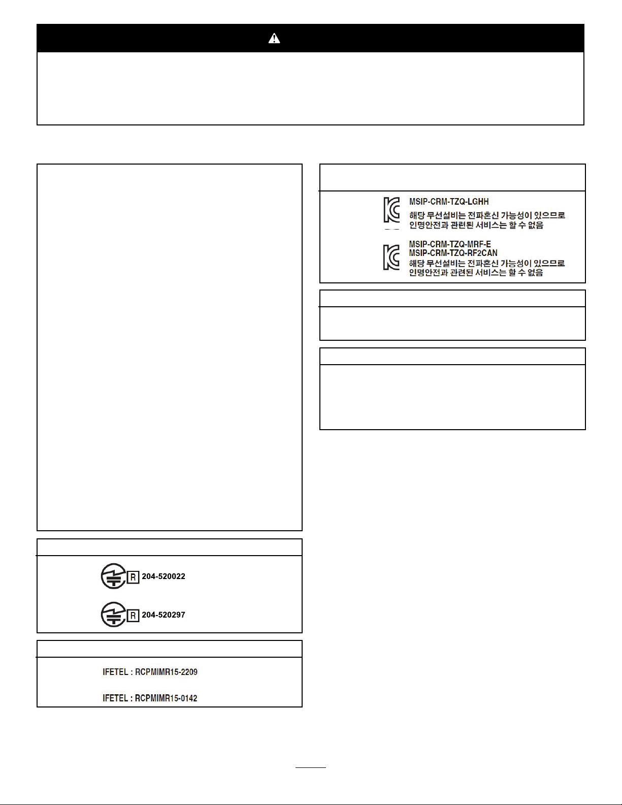
MexicoElectromagneticCompatibilityCertication
Handheld:
KoreaElectromagneticCompatibilityCertication(Decal
providedinseparatekit)
Handheld:
RF2CAN:
SingaporeElectromagneticCompatibilityCertication
Handheld:TWM240008_IDA_N4023-15
RF2CAN:
MoroccoElectromagneticCompatibilityCertication
AGREEPARL’ANRTMAROC
NUMEROd’agrement:
Delivred'agrement::
TWM-240005_IDA_N4024-15
MR14078ANRT2017
29/05/2017
Introduction
Thismachineisintendedtobeusedbyprofessional,
hiredoperatorsincommercialapplications.Itis
designedprimarilyformeteringanddispersing
materials,underarangeofmoistureconditions,
withoutcloggingordrasticallyaffectingthedispersion.
Important:Tomaximizethesafety ,performance,
andproperoperationofthismachine,carefully
readandfullyunderstandthecontentsofthis
Operator’sManual.Failingtofollowthese
operatinginstructionsortoreceiveproper
trainingmayresultininjury.Formoreinformation
onsafeoperatingpractices,includingsafetytips
andtrainingmaterials,gotowww.Toro.com.
RF2CAN:
©2017—TheToro®Company
8111LyndaleAvenueSouth
Bloomington,MN55420
Wheneveryouneedservice,genuineToroparts,or
additionalinformation,contactanAuthorizedService
DealerorToroCustomerServiceandhavethemodel
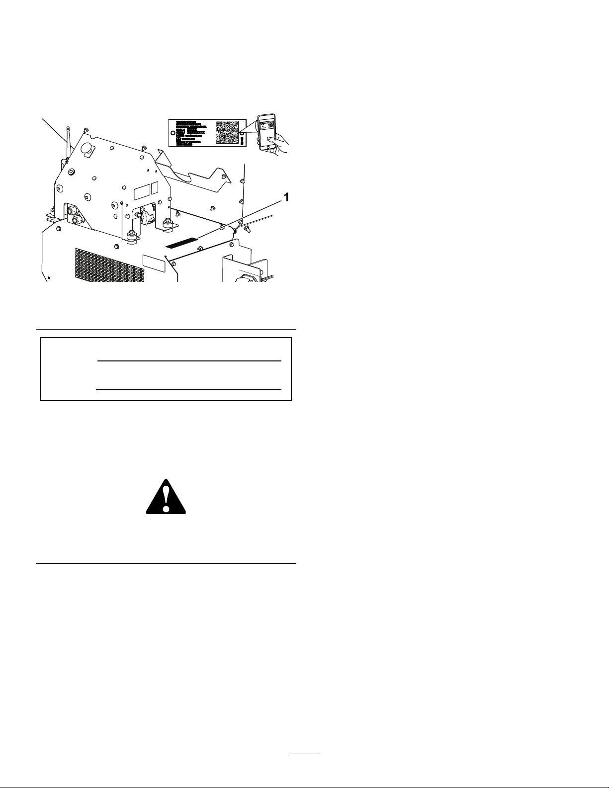
andserialnumbersofyourproductready.Figure1
identiesthelocationofthemodelandserialnumbers
Contactusatwww.Toro.com.
2
PrintedintheUSA
AllRightsReserved
ontheproduct.Writethenumbersinthespace
provided.
Contents
Important:Withyourmobiledevice,youcan
scantheQRcode(ifequipped)ontheserial
numberdecaltoaccesswarranty,parts,andother
productinformation.
Figure1
1.Modelandserialnumberlocation
ModelNo.
SerialNo.
Thismanualidentiespotentialhazardsandhas
safetymessagesidentiedbythesafety-alertsymbol
(Figure2),whichsignalsahazardthatmaycause
seriousinjuryordeathifyoudonotfollowthe
recommendedprecautions.
Figure2
1.Safety-alertsymbol
Thismanualuses2wordstohighlightinformation.
Importantcallsattentiontospecialmechanical
informationandNoteemphasizesgeneralinformation
worthyofspecialattention.
Safety.......................................................................4
GeneralSafety...................................................4
SafetyandInstructionalDecals..........................5
Setup........................................................................8
1SettingUptheMachineBaseModel
........................................................................9
2InstallingthePowerHarness..........................10
3InstallingtheHopperExtensionKit..................11
4MountingtheHoppertotheT ow
Chassis.........................................................12
5ConnectingtheIntermediateWire
Harness........................................................12
6ConnectingtheOn/OffPendant.....................13
7AssemblingtheHandheldRemote.................13
8MountingtheWirelessRemote......................14
ProductOverview...................................................15
Controls...........................................................15
Specications..................................................17
g237535
Attachments/Accessories.................................17
Operation................................................................18
BeforeOperationSafety...................................18
OperatingCharacteristics.................................18
ConnectingtheMachinetoaTow
Vehicle..........................................................18
TurningtheMachinePowerOn/Off...................19
PreparingtheMachineforOperation................20
DuringOperationSafety...................................23
SlopeSafety.....................................................24
OperatingtheMachine.....................................24
WirelessControllerSafety(Model44751
only)..............................................................25
DisconnectingtheMachinefromaT ow
Vehicle..........................................................25
OperatingtheHydraulicControlsand
Options.........................................................25
OperatingtheFloorandOption.........................31
SettingthePreset1,2,and3Buttons................33
UsingaPresetMode........................................34
g000502
ChoosingaT owVehicle....................................34
LoadingtheHopper..........................................34
UnloadingtheHopper.......................................34
Traveling...........................................................35
AfterOperationSafety......................................35
ParkingtheMachine.........................................35
UsingtheStorageStand...................................36
Maintenance...........................................................38
Pre-MaintenanceSafety...................................38
Lubrication........................................................38
DailyChecks....................................................39
HydraulicSystem.............................................39
MaintainingtheConveyorBeltSystem..............40
WashingtheMachine.......................................41
Storage...................................................................42
Troubleshooting......................................................43
CheckingFaultCodes(EHModels
Only).............................................................43
3

HandheldRemoteMessages(EHModels
Only).............................................................44
Safety
GeneralSafety
Thisproductiscapableofcausingpersonalinjury.
Alwaysfollowallsafetyinstructionstoavoidserious
personalinjury.
Usingthisproductforpurposesotherthanitsintended
usecouldprovedangeroustoyouandbystanders.
•Readandunderstandthecontentsofboththis
Operator’sManualandtheoperator’smanualof
thetowvehiclebeforeusingthismachine.Ensure
thateveryoneusingthisproductknowshowtouse
thismachineandthetowvehicleandunderstands
thewarnings.
•Donotputyourhandsorfeetnearmoving
componentsofthemachine.
•Donotoperatethemachinewithoutallguards
andothersafetyprotectivedevicesinplaceand
workingonthemachine.
•Keepthemachineasafedistanceawayfrom
bystanderswhileitismoving.
•Keepchildrenoutoftheoperatingarea.Never
allowchildrentooperatethemachine.
•Stopthemachine,shutofftheengine,engagethe
parkingbrake,removethekey,andwaitforall
movingpartstostopbeforeservicing,fueling,or
uncloggingthemachine.
Improperlyusingormaintainingthismachinecan
resultininjury .Toreducethepotentialforinjury,
complywiththesesafetyinstructionsandalwayspay
attentiontothesafety-alertsymbol,whichmeans
Caution,Warning,orDanger—personalsafety
instruction.Failuretocomplywiththeseinstructions
mayresultinpersonalinjuryordeath.
Youcanndadditionalsafetyinformationwhere
neededthroughoutthismanual.
4

SafetyandInstructionalDecals
Safetydecalsandinstructionsareeasilyvisibletotheoperatorandarelocatednearanyarea
ofpotentialdanger.Replaceanydecalthatisdamagedormissing.
119-6809
1.ReadtheOperator'sManualforinstructionsoncleaning
themachine.
decal119-6809
119-6854
decal119-6854
1.Floorspeed
decal119-6853
119-6853
1.Spinnerspeed
decal115-2047
115-2047
1.Warning—donottouchthehotsurface.
1.Tailgateheightindicator
1.Tailgateadjustment
decal119-6808
119-6808
decal119-0217
119-0217
1.Warning—shutofftheengine;stayawayfrommovingparts;
keepallguardsandshieldsinplace.
decal119-6818
119-6818
5
1.Spinnerspeedadjustment
1.Spinnerspeed
1.Floorspeed
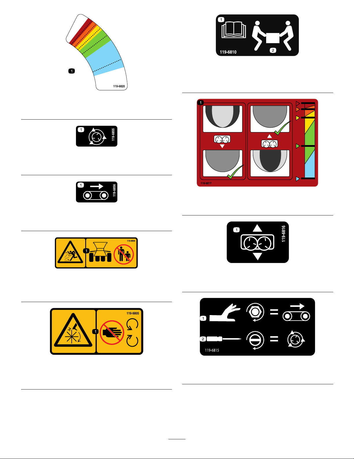
decal119-6810
119-6810
1.ReadtheOperator'sManual.
2.2peoplerequiredtolift.
decal119-6820
119-6820
decal119-6855
119-6855
decal119-6817
119-6817
decal119-6856
1.Finetuningspinners
119-6856
119-6804
1.Thrownobjecthazard—keepbystandersasafedistance
fromthemachine.
119-6805
1.Cutting/dismembermenthazard,impeller—stayawayfrom
movingparts,keepallguardsandshieldsinplace.
decal119-6804
119-6816
decal119-6816
1.Slideadjustment
decal119-6805
decal119-6815
119-6815
1.Floorspeedadjustment
2.Spinnerspeedadjustment
6
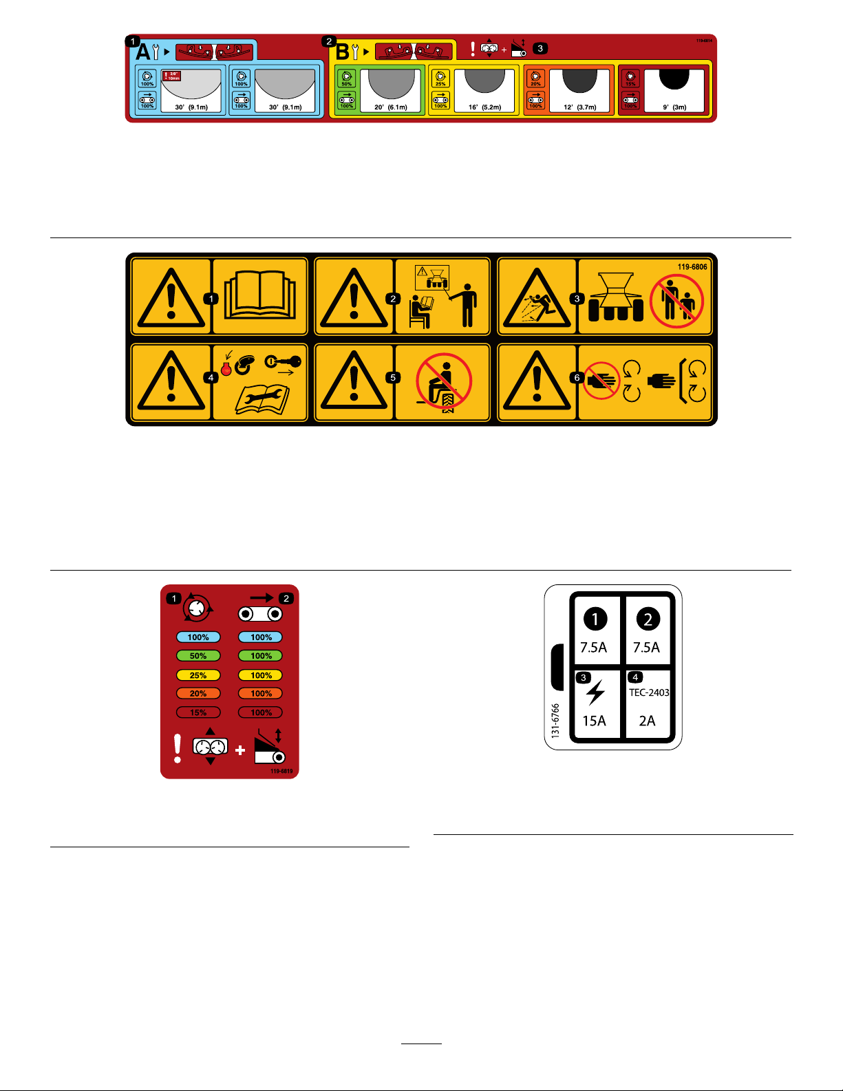
decal119-6814
119-6814
1.Lightspreadspinneradjustmentsettings(refertothe
3.Warning—slideadjustmentandtailgateadjustment.
Operationsectionformoreinformation).
2.Heavyspreadspinneradjustmentsettings(refertothe
Operationsectionformoreinformation).
119-6806
1.Warning—readtheOperator'sManual.4.Warning—shutofftheengine,removetheignitionkey,and
2.Warning—donotoperatethemachineunlessyouaretrained.5.Warning—noridersonthemachine
3.Thrownobjecthazard—keepbystandersasafedistancefrom
themachine.
readtheOperator'sManualbeforeperformingmaintenance
onthemachine.
6.Warning—stayawayfrommovingparts;keepallguardsand
shieldsinplace.
decal119-6806
1.Spinnerspeedpercentage
decal131-6766
131-6766
decal119-6819
119-6819
2.Beltspeedpercentage
1.7.5A3.Electricalaccessory—15A
2.7.5A
4.TEC-2403—2A
7

Setup
LooseParts
Usethechartbelowtoverifythatallpartshavebeenshipped.
ProcedureDescription
1
2
3
4
5
6
7
8
Hopperguard1
Buttonheadbolt(1/4x5/8inch)
Locknut3
Powerharness1
Socketbracket
Socketbracket,heavy
Carriagescrew
Flangenut2
Screw
Flangenut2
Hopperextension(front)
Hopperextension(rear)
Bolt9
Flangenut9
Bolt6
Flangenut6
Intermediatewireharness1
On/offpendant
Handheldremote1
AAbatteries4
Magneticbracket1
Screws,small
Controllermountassembly
Wirelessremoteassembly1
Qty.
Use
3
1
1
2
2
1
1
1
6
1
Setupthemachinebasemodel.
Installthepowerharness.
Installthehopperextensionkit.
Mountthehoppertothetowchassis.
Connecttheintermediatewireharness.
Connecttheon/offpendant(Model
44701only).
Assemblethehandheldremote(Model
44751only).
Mountthewirelessremote(Model
44751only).
MediaandAdditionalParts
Description
Operator’sManual
DeclarationofConformity
Note:Determinetheleftandrightsidesofthemachinefromthenormaloperatingposition.
Qty.
1
1Ensureregulatorycompliance.
Readbeforeoperatingthemachine.
8
Use
1
SettingUptheMachine BaseModel
Partsneededforthisprocedure:
1Hopperguard
3
Buttonheadbolt(1/4x5/8inch)
3Locknut
Procedure
1.Removethebasemodelmachinefromthe
shippingcrate.
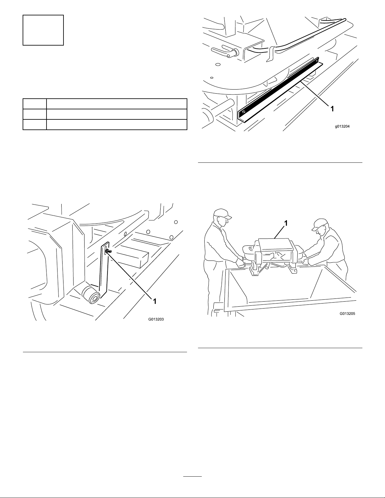
2.Attherearofthetwinspinner,removethebolt
andnutattachingthemachineliftingdevice
shippingbrackettothetwinspinner(Figure3).
g013204
Figure4
1.Shippingbracket
4.Liftthetwinspinneroutofthehopperusingthe
twinspinneroutergrabhandlesandplacethe
twinspinnerunitontheground(Figure5).
Note:Thissteprequires2people.
Figure3
1.Shippingbracket
3.Atthefrontofthetwinspinner,removethe2
boltsandnutsattachingthemachinelifting
deviceshippingbrackettotheTwinSpinner
(Figure4).
g013203
1.Twinspinner
5.Removethe4screwsfromthelegsofthetwin
spinner.Withthehelpofapartner,liftthetwin
spinnerandremovethepackingstudsand
packingfoam(Figure6).
9
Figure5
g013205
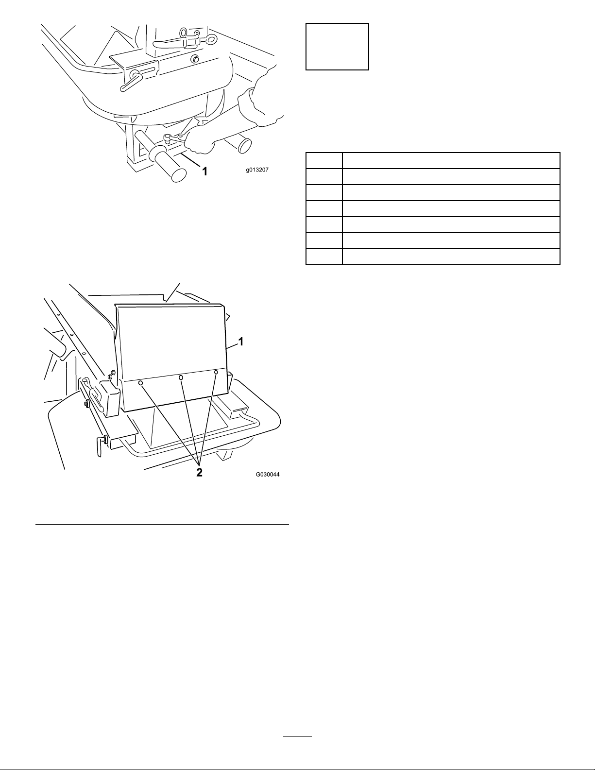
Figure6
1.Packingstudsandfoam
6.Installthehopperguardusingthesupplied
button-headbolts(1/4x5/8inch)andnylon
locknuts(Figure7).
2
InstallingthePower Harness
Partsneededforthisprocedure:
1Powerharness
1
g013207
Procedure
Thetowvehiclepowerharnessprovidestheelectrical
powerrequiredbythecontrolsystemsofthemachine.
Installthisharnessonthevehicleyouplantouse
tooperatethemachine.Ifyouwillusemorethan1
vehiclewiththemachine,purchaseadditionalpower
harnessesfromyourTorodistributor.
Socketbracket
1
Socketbracket,heavy
2
Carriagescrew
2Flangenut
2
Screw
2Flangenut
1.Hopperfrontguard
Figure7
1.Mountthesocketbrackettoaxedpointatthe
rearofthetowvehicleusing1ofthemounting
bracketsprovided(Figure8).
Note:Ensurethatthebracketwillnotcome
incontactwithanythingifthetowvehicleis
equippedwithadumpbox.
g030044
2.Bolts
Important:Ensurethatnoneofthewiring
islooseorinthewayofanymechanical
components.
10

Figure8
3
InstallingtheHopper ExtensionKit
Partsneededforthisprocedure:
1
Hopperextension(front)
1
Hopperextension(rear)
9Bolt
g013261
9Flangenut
1.Socketbracket
2.Routeandsecuretheelectricalwiringfromthe
batterytotheelectricalplugbracket(Figure9).
Figure9
1.Whitewire(brass)3.Nowire(brass)
2.Nowiresilver(silver)4.Blackwire(brass)
3.Feedthewiringthroughthesocketbracketand
installtheblackrubbergrommetoverthewiring
(Figure9).
4.Boltthesockettothesocketbracketusingthe
bolts(1/4inch).
Procedure
1.Removethehopperextensionsfromthebox
andidentifythefrontandtherear(Figure10
andFigure11).
g013263
Figure10
1.Fronthopperextension(showingholeorientation)
g013262
g013264
Figure11
1.Rearhopperextension(showingholeorientation)
2.Usingthehardwareprovided,attachthehopper
extensionstothehopper.Placethenutsonthe
outsideofthehopper.
5.Connecttheredwire(power)tothepositive
postonthebattery,thenconnecttheblackwire
(ground)tothenegativepostonthebattery.
11
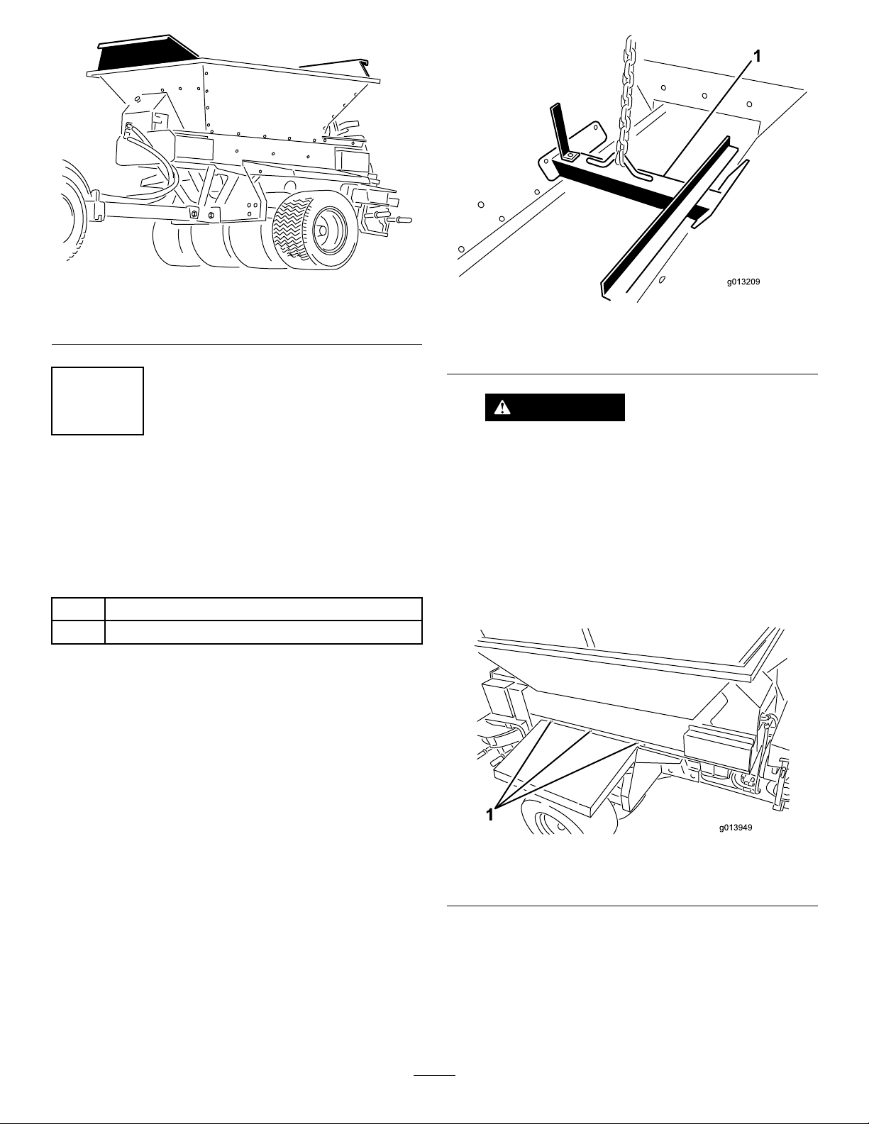
Figure12
Hopperextensionkitinstalled
g237533
g013209
Figure13
1.Liftingbracket
4
MountingtheHoppertothe TowChassis
TowChassisCongurationOnly
Partsneededforthisprocedure:
6Bolt
6Flangenut
Procedure
Note:IfyouaremountingtheProPasstopdresser
ontosomethingotherthanthetowchassis,referto
theinstallationinstructionsforyourapplication.
1.Attachaliftingdevicetotheliftingbracketbolted
insidethehopperassembly(Figure13).
WARNING
Donotattempttoliftthebedandhopper
withtheTow-BehindChassis,ProGator,
Workman,orTDCChassisconnected.
Theliftingbracketisnotcapableoflifting
theentiremachine.
2.Usingaliftingmechanism,positionthehopper
overthetowchassis.
3.Lineupthe6mountingholes(3perside)and
installthe5/16x1inchboltsandangenuts.
Figure14
1.Mountinglocations(3eachside)
4.Removetheliftingbracketfromthehoppersides
andinstalltheboltstothehoppersides.
Note:Retaintheliftingbracketforfutureuse;
donotdiscardit.
12
g013949
5
6
Connectingthe
IntermediateWireHarness
Partsneededforthisprocedure:
1Intermediatewireharness
Procedure
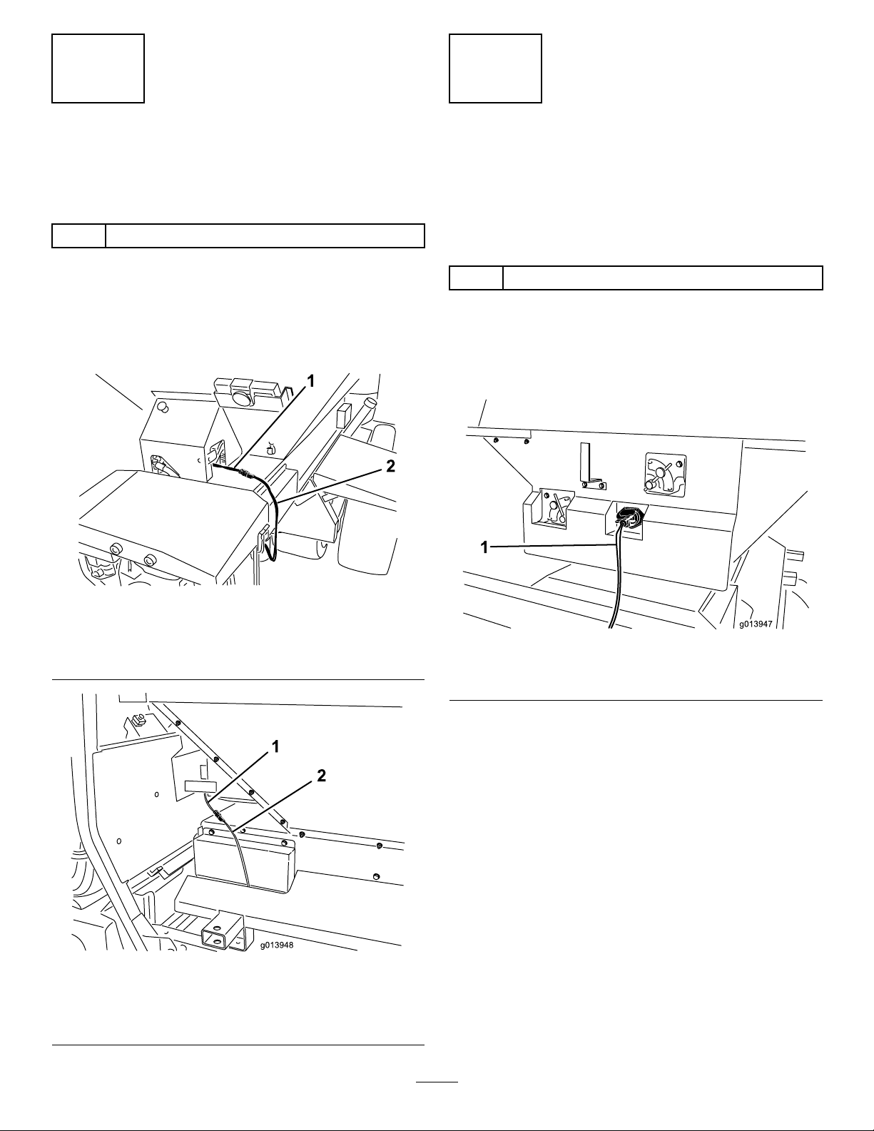
Plugtheintermediatewireharnessintothepower
harnessconnectoronthemachine(Figure15or
Figure16).
ConnectingtheOn/Off Pendant
Model44701Only
Partsneededforthisprocedure:
1
On/offpendant
Procedure
Plugtheon/offpendantconnectorintotheconnector
onthemachine(Figure17).
Figure15
Model44751
1.Powerharness2.Intermediatewireharness
Figure16
Model44701
g237534
g013947
Figure17
1.On/offpendant
g013948
1.Powerharness2.Intermediatewireharness
13

4.Securethecoverwith6screws(Figure18)and
torquethemto1.5to1.7N∙m(13to15in-lb).
7
AssemblingtheHandheld
Remote
Model44751Only
Partsneededforthisprocedure:
1Handheldremote
4AAbatteries
1Magneticbracket
6
Screws,small
Procedure
1.Removetherubberbandssecuringtheremote
halvestogether,andremovethebackcover.
2.Installthebatteriesintotheterminalcradle
observingproperpolarity.(Ifthebatteries
areimproperlyinstalled,theunitwillnotbe
damaged,butitwillfailtooperate.)Thecradle
isembossedwithpolaritymarkingsforeach
terminal(Figure18).
5.Installthehandheldremoteintothemagnetic
remotebracket,slidethehalvestogetherto
securetheremote,andtightentheboltinthe
magnet(Figure19).
g028874
Figure19
1.Handheldremote3.Boltinthemagnet
2.Magneticremotebracket
Figure18
1.Rubberseal3.Handheldremote
2.Steelgasket
3.Ensurethatthesteelgasketandrubbersealare
seatedinthechannelintheremoteandsetthe
backcoverinplace(Figure18).
4.4AAbatteries
8
MountingtheWireless Remote
Model44751Only
Partsneededforthisprocedure:
1
Controllermountassembly
1Wirelessremoteassembly
Procedure
g028875
Insertthecontrollermountassemblyintoacupholder
orsimilaropeningonthetowvehicleandusetostore
wirelessremote.Also,thewirelessremotemagnet
willsticktoanymetalcomponent.
14
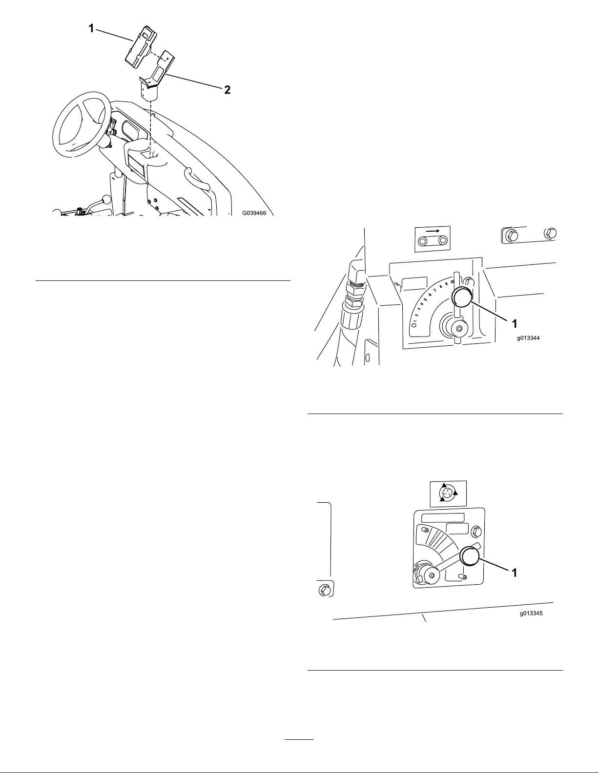
Figure20
WorkmanHeavyDutyVehicleShown
ProductOverview
Controls
FlowControlValveforFloor
Model44701Only
Ahydraulicowcontrolvalvecontrolsthespeedof
theconveyorbelt.
Thehighestspeedsettingis10andistypicalformost
applicationsfoundontheColor-CodedOperation
Systemdecals.Uselowersettingsforverylight
g030466
applications.
1.Remote
2.Controllermountassembly
g013344
Figure21
1.Floorcontrolvalve
FlowControlValveforOptions
Model44701Only
1.Optioncontrolvalve
15
g013345
Figure22
 Loading...