


FormNo.3432-306RevE
ProLineCommercialWalk-Behind
Mower
with36in,48in,54in,or60inCuttingUnit
ModelNo.44409—SerialNo.400000000andUp
ModelNo.44410—SerialNo.400000000andUp
ModelNo.44423—SerialNo.400000000andUp
ModelNo.44424—SerialNo.400000000andUp
ModelNo.44427—SerialNo.400000000andUp
ModelNo.44430—SerialNo.400000000andUp
ModelNo.44436—SerialNo.400000000andUp
ModelNo.44448—SerialNo.400000000andUp
ModelNo.44454—SerialNo.400000000andUp
ModelNo.44460—SerialNo.400000000andUp
Registeratwww.T oro.com.
OriginalInstructions(EN)
*3432-306*

ItisaviolationofCaliforniaPublicResourceCode
Section4442or4443touseoroperatetheengineon
anyforest-covered,brush-covered,orgrass-covered
landunlesstheengineisequippedwithaspark
arrester,asdenedinSection4442,maintainedin
effectiveworkingorderortheengineisconstructed,
equipped,andmaintainedforthepreventionofre.
Theenclosedengineowner'smanualissupplied
forinformationregardingtheUSEnvironmental
ProtectionAgency(EPA)andtheCaliforniaEmission
ControlRegulationofemissionsystems,maintenance,
andwarranty.Replacementsmaybeorderedthrough
theenginemanufacturer.
Pleaserefertotheenginemanufacturer’sinformation
includedwiththemachine.
WARNING
CALIFORNIA
Proposition65Warning
Theengineexhaustfromthisproduct
containschemicalsknowntotheStateof
Californiatocausecancer,birthdefects,
orotherreproductiveharm.
Batteryposts,terminals,andrelated
accessoriescontainleadandlead
compounds,chemicalsknownto
theStateofCaliforniatocause
cancerandreproductiveharm.Wash
handsafterhandling.
Useofthisproductmaycauseexposure
tochemicalsknowntotheStateof
Californiatocausecancer,birthdefects,
orotherreproductiveharm.
Visitwww.Toro.comformoreinformation,including
safetytips,trainingmaterials,accessoryinformation,
helpndingadealer,ortoregisteryourproduct.
Wheneveryouneedservice,genuineToroparts,or
additionalinformation,contactanAuthorizedService
DealerorToroCustomerServiceandhavethemodel
andserialnumbersofyourproductready.Figure1
identiesthelocationofthemodelandserialnumbers
ontheproduct.Writethenumbersinthespace
provided.
Important:Withyourmobiledevice,youcan
scantheQRcodeontheserialnumberdecal(if
equipped)toaccesswarranty,parts,andother
productinformation.
g291703
Figure1
1.Modelandserialnumberlocation
ModelNo.
SerialNo.
Thismanualidentiespotentialhazardsandhas
safetymessagesidentiedbythesafety-alertsymbol
(Figure2),whichsignalsahazardthatmaycause
seriousinjuryordeathifyoudonotfollowthe
recommendedprecautions.
Introduction
Thisrotary-bladelawnmowerisintendedtobeused
byresidentialhomeownersorprofessional,hired
operators.Itisdesignedprimarilyforcuttinggrasson
well-maintainedlawnsonresidentialorcommercial
properties.Usingthisproductforpurposesotherthan
itsintendedusecouldprovedangeroustoyouand
bystanders.
Readthisinformationcarefullytolearnhowtooperate
andmaintainyourproductproperlyandtoavoid
injuryandproductdamage.Youareresponsiblefor
operatingtheproductproperlyandsafely .
©2020—TheToro®Company
8111LyndaleAvenueSouth
Bloomington,MN55420
Figure2
Safety-alertsymbol
Thismanualuses2wordstohighlightinformation.
Importantcallsattentiontospecialmechanical
informationandNoteemphasizesgeneralinformation
worthyofspecialattention.
2
g000502
Contactusatwww.Toro.com.
PrintedintheUSA
AllRightsReserved

Contents
Safety.......................................................................4
GeneralSafety...................................................4
SafetyandInstructionalDecals..........................4
ProductOverview.....................................................8
Controls.............................................................8
Specications....................................................9
Attachments/Accessories...................................9
BeforeOperation.................................................10
BeforeOperationSafety...................................10
AddingFuel......................................................10
UsingtheSafety-InterlockSystem.....................11
PerformingDailyMaintenance..........................12
DuringOperation.................................................12
DuringOperationSafety...................................12
OperatingtheParkingBrake.............................13
StartingtheEngine...........................................14
ShuttingOfftheEngine.....................................14
OperatingtheMower-Blade-ControlSwitch
(PTO)............................................................15
DrivingtheMachine..........................................16
UsingtheAdjustableReferenceBar.................17
SideDischargingorMulchingGrass.................17
AdjustingtheHeightofCut...............................18
AdjustingtheAnti-ScalpRollers........................19
AfterOperation....................................................19
AfterOperationSafety......................................19
UsingtheFuel-ShutoffValve.............................19
PushingtheMachinebyHand..........................20
TransportingtheMachine.................................20
Maintenance...........................................................22
MaintenanceSafety..........................................22
RecommendedMaintenanceSchedule(s)...........22
Pre-MaintenanceProcedures..............................23
RemovingtheMowerDeckGuard....................23
Lubrication..........................................................24
GreasingtheMachine.......................................24
GreasingtheFrontCasterPivots......................24
GreasingtheCasterWheelBearings................24
EngineMaintenance...........................................25
EngineSafety...................................................25
ServicingtheAirCleaner..................................25
ServicingtheEngineOil....................................27
ServicingtheSparkPlug...................................30
FuelSystemMaintenance...................................31
DrainingtheFuelT ank......................................31
ReplacingtheFuelFilter...................................32
ElectricalSystemMaintenance...........................33
ElectricalSystemSafety..................................33
ServicingtheBattery.........................................33
ServicingtheFuses..........................................34
DriveSystemMaintenance..................................35
CheckingtheTirePressure...............................35
CheckingtheWheel-LugNuts..........................35
AdjustingtheNeutralTraction...........................35
AdjustingtheTracking......................................35
AdjustingtheCaster-PivotBearings.................36
ServicingtheCasterWheelsand
Bearings........................................................36
CoolingSystemMaintenance..............................37
CleaningtheAir-IntakeScreen.........................37
CleaningtheCoolingSystem............................37
BrakeMaintenance.............................................38
TestingtheParkingBrake.................................38
AdjustingtheParkingBrake..............................38
BeltMaintenance................................................39
InspectingtheBelts..........................................39
ReplacingtheMower-DeckBelt........................39
AdjustingtheIdlerPulleyArm...........................41
ReplacingtheTransmissionBelt.......................41
ControlsSystemMaintenance.............................43
AdjustingtheMotion-ControlLevers.................43
HydraulicSystemMaintenance...........................44
HydraulicSystemSafety...................................44
HydraulicSystemSpecications.......................44
CheckingtheHydraulicFluidLevel...................44
ChangingtheHydraulicFluidand
Filters............................................................44
BleedingtheHydraulicSystem.........................46
MowerDeckMaintenance....................................47
BladeSafety.....................................................47
ServicingtheCuttingBlades.............................47
LevelingtheMowerDeck..................................49
ReplacingtheGrassDeector..........................50
Cleaning..............................................................52
CleaningundertheMower................................52
DisposingofWaste...........................................52
Storage...................................................................53
StorageSafety..................................................53
CleaningandStoringtheMachine....................53
Troubleshooting......................................................54
Schematics.............................................................56
3
Safety
Thismachinehasbeendesignedinaccordancewith
ANSIB71.4-2017.
GeneralSafety
Thisproductiscapableofamputatinghandsand
feetandofthrowingobjects.Alwaysfollowallsafety
instructionstoavoidseriouspersonalinjury.
•Read,understand,andfollowtheinstructions
andwarningsinthisOperator’sManualandon
themachineandattachmentsbeforestartingthe
engine.
•Donotputyourhandsorfeetnearmovingpartsof
orunderthemachine.Keepclearofanydischarge
opening.
•Donotoperatethemachinewithoutallguards
andothersafetyprotectivedevicesinplaceand
functioningproperlyonthemachine.
•Keepbystandersandchildrenoutoftheoperating
area.Donotallowchildrentooperatethemachine.
Allowonlypeoplewhoareresponsible,trained,
familiarwiththeinstructions,andphysically
capabletooperatethemachine.
•Stopthemachine,shutofftheengine,remove
theignitionkey(ifequipped),andwaitforall
movingpartstostopbeforeservicing,fueling,or
uncloggingthemachine.
Improperlyusingormaintainingthismachinecan
resultininjury.T oreducethepotentialforinjury,
complywiththesesafetyinstructionsandalways
payattentiontothesafety-alertsymbol
meansCaution,Warning,orDanger—personalsafety
instruction.Failuretocomplywiththeseinstructions
mayresultinpersonalinjuryordeath.
,which
SafetyandInstructionalDecals
Safetydecalsandinstructionsareeasilyvisibletotheoperatorandarelocatednearanyarea
ofpotentialdanger.Replaceanydecalthatisdamagedormissing.
Manufacturer'sMark
1.Thismarkindicatesthatthebladeisidentiedasapart
fromtheoriginalmachinemanufacturer.
decaloemmarkt
decalbatterysymbols
BatterySymbols
Someorallofthesesymbolsareonyourbattery .
1.Explosionhazard6.Keepbystandersaway
2.Nore,opename,or
smoking
3.Causticliquid/chemical
burnhazard
4.Weareyeprotection.9.Flusheyesimmediately
5.ReadtheOperator's
Manual.
fromthebattery .
7.Weareyeprotection;
explosivegasescan
causeblindnessandother
injuries.
8.Batteryacidcancause
blindnessorsevereburns.
withwaterandgetmedical
helpfast.
10.Containslead;donot
discard
4
93-7818
1.Warning—readtheOperator'sManualforinstructionson
torquingthebladebolt/nutto1 15to149N∙m(85to1 10
ft-lb).
98-1977
1.Entanglementhazard,belt—stayawayfrommovingparts.
116-5988
decal93-7818
decal126-1400
126-1400
1.Warning—readtheOperator’sManualforinformationabout
attachments;certainattachmentscancauseyoutofall.
decal98-1977
decal130-0731
130-0731
1.Warning—thrownobject
hazard;keepthedeector
shieldinplace.
2.Cuttinghazardofhandor
foot,mowerblade—keep
awayfrommovingparts.
Decal130-0765isfor122cm(48-inch),137cm
(54-inch),and152cm(60-inch)modelsonly.
decal116-5988
1.Parkingbrake—engaged2.Parking
brake—disengaged
Decal117-1 194isfor122cm(48-inch),137cm
(54-inch),and152cm(60-inch)modelsonly.
117-1194
decal117-1 194
1.ReadtheOperator's
Manual.
2.Height-of-cutselection
decal130-0765
130-0765
3.Removethekeybefore
performingmaintenance.
1.Beltrouting
2.Engine
5

131-3536
1.Battery4.Parkingbrake
2.Time5.Engine—start
3.Powertakeoff(PTO)
6.Engagethehandlebars.
decal131-3536
1.PTO—disengage
138-8816
4.Neutral
decal138-8816
2.Fast5.Reverse
3.Slow
6.Tractioncontrols
1.Thrownobject
hazard—keepbystanders
awayfromthemachine.
2.Thrownobjecthazard,
opendeector—only
operatethemachinewith
adeectororagrass
collector.
133-4604
3.Severinghazardofhand
4.Entanglement
133-8062
decal133-4604
orfoot—keepawayfrom
movingparts.
hazard—keepaway
frommovingparts;keep
allguardsandshieldsin
place.
decal133-8062
1.Disengagethehydrostatic
drivetopushthemachine.
1.Heightofcut
decal138-8820
138-8820
2.Engagethehydrostatic
drivetooperatethe
machine.
decal138-8821
138-8821
6
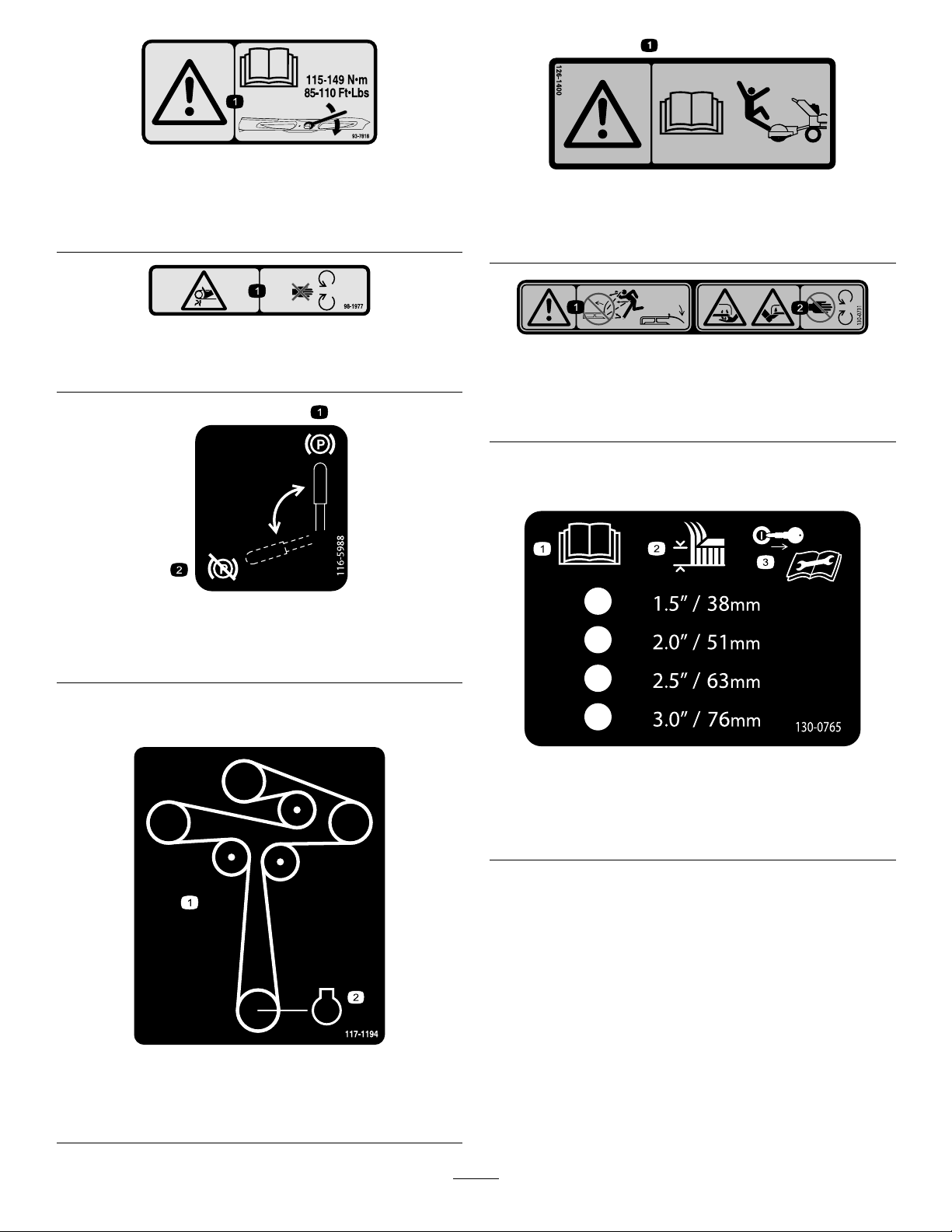
Decal139-7936isfor91cm(36-inch)modelsonly.
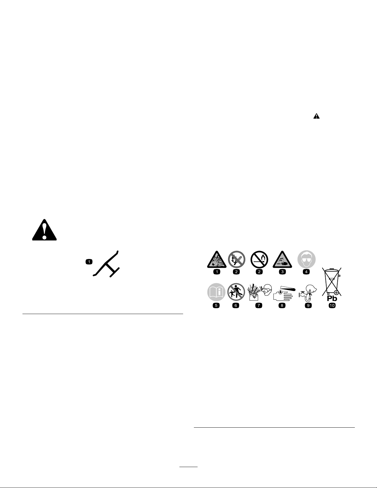
decal139-2874
139-2874
1.Tractioncontrols4.Neutral
2.Fast5.Reverse
3.Slow6.PTO—disengage
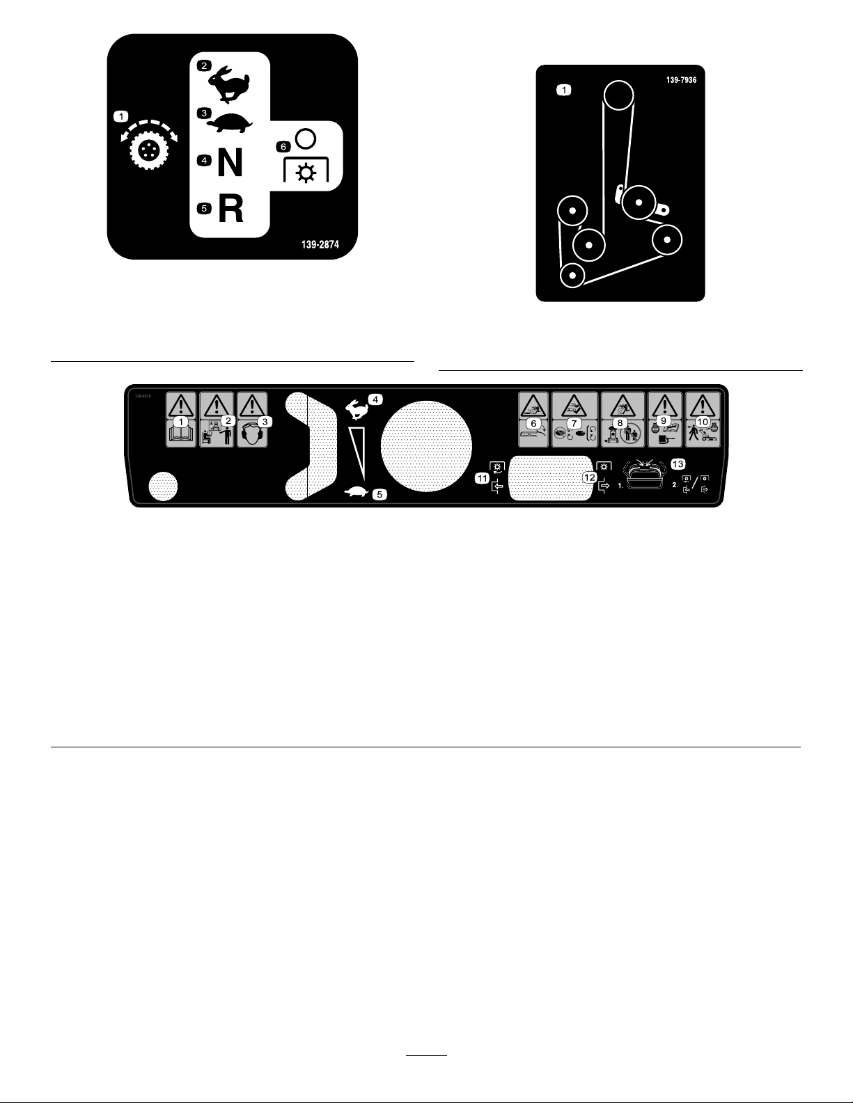
1.Warning—readtheOperator’sManual.
2.Warning—alloperatorsshouldbetrainedbeforeoperating
themachine.
3.Warning—wearhearingprotection.
4.Fast
5.Slow12.PTO—disengage
6.Thrownobjecthazard—lowerthedeectorbeforeusingthe
machine.
7.Cutting/dismembermenthazardofhandandfoot;mower
blade—stayawayfrommovingparts;keepallguardsand
shieldsinplace.
decal139-7936
139-7936
1.Beltrouting
decal138-8818
138-8818
8.Thrownobjecthazard—keepbystandersaway .
9.Warning—shutofftheengine,disconnectthesparkplug,and
readtheOperator’sManualbeforeperformingmaintenance.
10.Warning—shutofftheenginebeforeleavingthemachine.
11.PTO—engage
13.MovethetractioncontrolleverstotheNeutralposition;
engageordisengagethePTO.
7

ProductOverview
Figure3
1.Sidedischarge5.Controlpanel
2.Height-of-cutlever
3.Engine7.Mowerdeck
4.Fueltank8.Anti-scalproller
6.Parking-brakelever
Controls
ControlPanel
g299386
g299567
1.Parking-brakelever
2.Adjustablereferencebar
3.Leftmotion-controllever
4.Hourmeter10.Throttlecontrol
5.Referencebaradjustment
lever
6.Rightmotion-controllever
Figure4
7.Rearreferencebar
8.Blade-controlswitch
(PTO)
9.Keyswitch
11.Chokecontrol
ThrottleControl
Thethrottlecontrolstheenginespeed,andithasa
continuous-variablesettingfromtheSLOWtoFAST
position(Figure4).
Blade-ControlSwitch(Power
Takeoff)
Theblade-controlswitch,representedbya
power-takeoff(PTO)symbol,engagesand
disengagespowertothemowerblades(Figure4).
Fuel-ShutoffValve
Closethefuel-shutoffvalvewhentransportingor
storingthemachine.
KeySwitch
Thekeyswitch,usedtostartandshutofftheengine,
has3positions:OFF,RUN,andST ART.
8
Choke
Specications
Usethechoketostartacoldengine.
HourMeter
Thehourmeterrecordsthenumberofhoursthe
enginehasoperated.Itoperateswhentheengine
isrunning.Usethesetimesforschedulingregular
maintenance(Figure4).
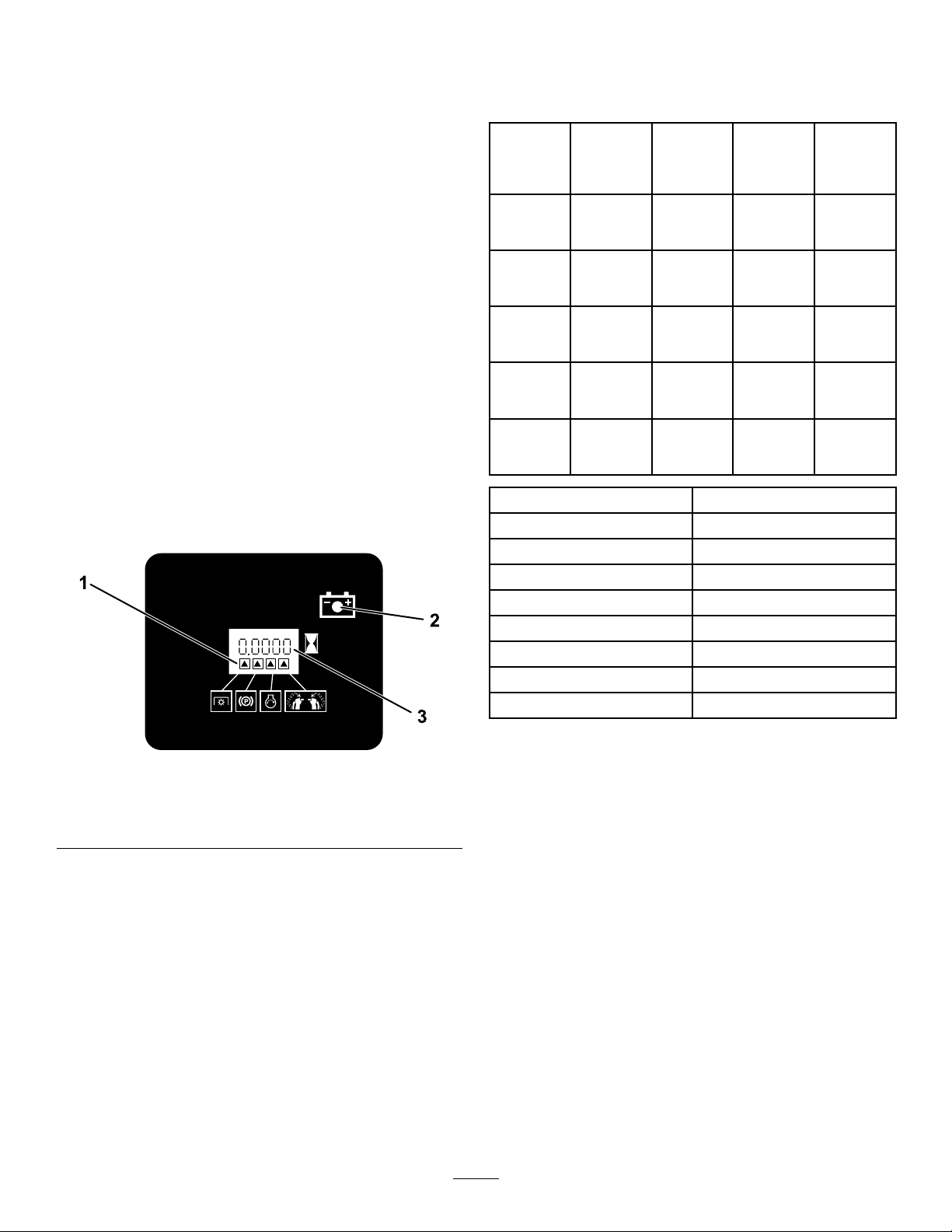
Safety-InterlockIndicators
Therearesymbolsonthehourmeterthatindicate
withablacktrianglethattheinterlockcomponentis
positionedcorrectly(Figure5).
Battery-IndicatorLight
IfyouturnthekeyswitchtotheONpositionfora
fewseconds,thebatteryvoltagedisplaysinthearea
wherethehoursarenormallydisplayed(Figure5).
Thebatterylightturnsonwhenthekeyswitchis
turnedonandwhenthechargeisbelowthecorrect
operatinglevel(Figure5).
Specicationsanddesignaresubjecttochange
withoutnotice.
Cutting
width
Widthwith
deector
down
Widthwith
deector
up
Height114
Length196
44409
44410
44423
44424
44427
44430
44448
44454
91cm
(36-inch)
Mower
Deck
91cm(36
inches)
130
cm(51
inches)
94cm(37
inches)
cm(45
inches)
cm(77
inches)
122cm
(48-inch)
Mower
Deck
122
cm(48
inches)
160
cm(63
inches)
124
cm(49
inches)
117
cm(46
inches)
203
cm(80
inches)
Weight
265kg(585lb)
263kg(580lb)
292kg(644lb)
290kg(639lb)
294kg(648lb)
314kg(693lb)
303kg(669lb)
315kg(695lb)
137cm
(54-inch)
Mower
Deck
137
cm(54
inches)
175
cm(69
inches)
140
cm(55
inches)
117
cm(46
inches)
203
cm(80
inches)
152cm
(60-inch)
Mower
Deck
152
cm(60
inches)
191
cm(75
inches)
155
cm(61
inches)
117
cm(46
inches)
211
cm(83
inches)
Figure5
1.Safety-interlockindicators
2.Batterylight
3.Hourmeter
Motion-ControlLevers
Usethemotion-controlleverstodrivethemachine
forward,reverse,andturneitherdirection(Figure4).
ReferenceBarAdjustmentLever
Usetheadjustmentlevertochangethepositionofthe
adjustablereferencebar(Figure4).
g216020
Attachments/Accessories
AselectionofT oroapprovedattachmentsand
accessoriesisavailableforusewiththemachine
toenhanceandexpanditscapabilities.Contact
yourAuthorizedServiceDealerorauthorizedT oro
distributororgotowww.T oro.comforalistofall
approvedattachmentsandaccessories.
Toensureoptimumperformanceandcontinuedsafety
certicationofthemachine,useonlygenuineToro
replacementpartsandaccessories.Replacement
partsandaccessoriesmadebyothermanufacturers
couldbedangerous,andsuchusecouldvoidthe
productwarranty.
9

Operation
Note:Determinetheleftandrightsidesofthe
machinefromthenormaloperatingposition.
BeforeOperation
BeforeOperationSafety
GeneralSafety
•Donotallowchildrenoruntrainedpeopleto
operateorservicethemachine.Localregulations
mayrestricttheageoftheoperator.Theowner
isresponsiblefortrainingalloperatorsand
mechanics.
•Becomefamiliarwiththesafeoperationofthe
equipment,operatorcontrols,andsafetysigns.
•Alwaysshutoffthemachine,removetheignition
key(ifequipped),waitforallmovingpartstostop,
andallowthemachinetocoolbeforeadjusting,
servicing,cleaning,orstoringit.
•Knowhowtostopthemachineandshutoffthe
enginequickly.
•Checkthatoperator-presencecontrols,safety
switches,andsafetyprotectivedevicesare
attachedandfunctioningproperly.Donotoperate
themachineunlesstheyarefunctioningproperly .
•Inspecttheareawhereyouwillusethemachine,
andremoveallobjectsthatcouldinterferewith
theoperationofthemachineorthatthemachine
couldthrow.
•Evaluatetheterraintodeterminewhataccessories
andattachmentsareneededtoproperlyand
safelyperformthejob.
•Beforeusing,alwaysvisuallyinspecttoseethat
theblades,bladeboltsandmowerdeckarenot
wornordamaged.Replacewornordamaged
bladesandboltsinsetstopreservebalance.
•Ifyouspillfuel,donotattempttostarttheengine;
avoidcreatingasourceofignitionuntilthefuel
vaporshavedissipated.
•Donotllcontainersinsideavehicleoronatruck
ortrailerbedwithaplasticliner.Alwaysplace
containersontheground,awayfromthevehicle
beforelling.
•Removeequipmentfromthetruckortrailerand
refuelitontheground.Ifthisisnotpossible,refuel
suchequipmentwithaportablecontainerrather
thanfromafuel-dispensernozzle.
•Keepthenozzleincontactwiththerimofthefuel
tankorcontaineroperatingatalltimesuntilfueling
iscomplete.
AddingFuel
RecommendedFuel
•Forbestresults,useonlyclean,fresh(lessthan
30daysold),unleadedgasolinewithanoctane
ratingof87orhigher((R+M)/2ratingmethod).
•Ethanol:Gasolinewithupto10%ethanol
(gasohol)or15%MTBE(methyltertiarybutyl
ether)byvolumeisacceptable.Ethanoland
MTBEarenotthesame.Gasolinewith15%
ethanol(E15)byvolumeisnotapprovedforuse.
Neverusegasolinethatcontainsmorethan
10%ethanolbyvolume,suchasE15(contains
15%ethanol),E20(contains20%ethanol),orE85
(containsupto85%ethanol).Usingunapproved
gasolinemaycauseperformanceproblemsand/or
enginedamagewhichmaynotbecoveredunder
warranty.
•Donotusegasolinecontainingmethanol.
•Donotstorefueleitherinthefueltankorfuel
containersoverthewinterunlessyouuseafuel
stabilizer.
•Donotaddoiltogasoline.
FuelSafety
•Useextremecareinhandlingfuel.Itisammable
anditsvaporsareexplosive.
•Extinguishallcigarettes,cigars,pipes,andother
sourcesofignition.
•Useonlyanapprovedfuelcontainer.
•Donotremovethefuelcaporaddfueltothetank
whiletheengineisrunningorhot.
•Donotaddordrainfuelinanenclosedspace.
•Donotstorethemachineorfuelcontainerwhere
thereisanopename,spark,orpilotlight,such
asonawaterheaterorotherappliance.
UsingStabilizer/Conditioner
Useafuelstabilizer/conditionerinthemachineto
providethefollowingbenets:
•Keepsfuelfreshlongerwhenusedasdirectedby
thefuel-stabilizermanufacturer
•Cleanstheenginewhileitruns
•Eliminatesgum-likevarnishbuildupinthefuel
system,whichcauseshardstarting
Important:Donotusefueladditives
containingmethanolorethanol.
Addthecorrectamountoffuelstabilizer/conditioner
tothefuel.
10

Note:Afuelstabilizer/conditionerismost
effectivewhenmixedwithfreshfuel.T ominimize
thechanceofvarnishdepositsinthefuelsystem,
usefuelstabilizeratalltimes.
FillingtheFuelTank
Figure6
g031282
Figure7
1.Thetriangleslightupwhentheinterlockcomponentsare
g302021
inthecorrectposition.
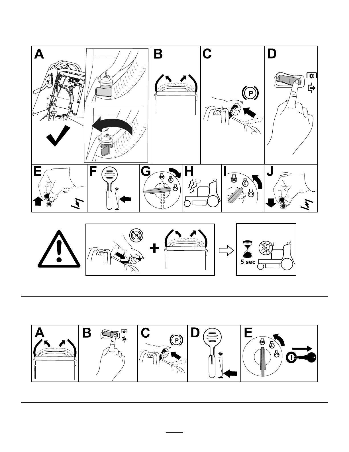
TestingtheSafety-Interlock
UsingtheSafety-Interlock
System
WARNING
Ifthesafety-interlockswitchesare
disconnectedordamaged,themachinecould
operateunexpectedly,causingpersonal
injury.
•Donottamperwiththeinterlockswitches.
•Checktheoperationoftheinterlock
switchesdailyandreplaceanydamaged
switchesbeforeoperatingthemachine.
Understandingthe
Safety-InterlockSystem
Thesafety-interlocksystemisdesignedtoprevent
PTOfromengagingunlessyoudothefollowing:
•Moveeithermotion-controllevertothecenter,
unlockedposition.
•PullthePTOswitchtotheONposition.
Thesafety-interlocksystemisdesignedtostop
theblades/attachmentifyoumoveorreleaseboth
motion-controlleversoutward.
Thehourmeterhassymbolstonotifytheuser
wheneachinterlockcomponentisinthecorrect
position.Whenthecomponentisinthecorrect
position,atrianglelightsupinthecorresponding
square(Figure7).
System
ServiceInterval:Beforeeachuseordaily
Testthesafety-interlocksystembeforeyouusethe
machineeachtime.
Note:Ifthesafetysystemdoesnotoperateas
describedbelow,haveanAuthorizedServiceDealer
repairthesafetysystemimmediately.
1.Engagetheparkingbrakeandstarttheengine.
2.Movethemotion-controlleverstothecenter,
unlockedposition.
Note:Theengineshouldshutoff.
3.Starttheengineanddisengagetheparking
brake.Donotmovethemotion-controllevers.
Note:Theengineshouldidle5secondsand
thenshutoff.
4.Engagetheparkingbrakeandstarttheengine.
5.PresstheONpositionforthePTOswitch.
Note:Themowerbladesshouldnotengage.
6.Disengagetheparkingbrake.
7.Holdeithermotion-controlleverinthecenter
positionandpresstheONpositionforthePTO
switch.
Note:Themowerbladesshouldengage.
8.Releasethemotion-controllever.
Note:Theengineshouldidle5secondsand
thenshutoff.
9.Engagetheparkingbrakeandstarttheengine.
10.Disengagetheparkingbrake.
11.Holdeithermotion-controllevertothecenter
positionandpresstheONpositionforthePTO
switch.
11

Note:Themowerbladesshouldengage.
12.PresstheOFFpositionforthePTOswitch.
Note:Themowerbladesshoulddisengage.
13.PresstheONpositionforthePTOswitch.
Note:Themowerbladesshouldengage.
14.Engagetheparkingbrake.
Note:Themowerbladesshoulddisengageand
theengineshouldshutoff.
15.PresstheONpositionforthePTOswitch.
16.Trystartingtheengine.
Note:Theengineshouldnotcrank.
PerformingDaily
Maintenance
Beforestartingthemachineeachday ,performthe
EachUse/DailyprocedureslistedinMaintenance
(page22).
DuringOperation
DuringOperationSafety
GeneralSafety
•Theowner/operatorcanpreventandisresponsible
foraccidentsthatmaycausepersonalinjuryor
propertydamage.
•Wearappropriateclothing,includingeye
protection;longpants;substantial,slip-resistant
footwear;andhearingprotection.Tiebacklong
hairanddonotwearlooseclothingorloose
jewelry.
•Useyourfullattentionwhileoperatingthe
machine.Donotengageinanyactivitythat
causesdistractions;otherwise,injuryorproperty
damagemayoccur.
•Donotoperatethemachinewhileill,tired,or
undertheinuenceofalcoholordrugs.
•Beforeyoustarttheengine,ensurethatalldrives
areinneutral,theparkingbrakeisengaged,and
youareintheoperatingposition.
•Keepbystandersoutoftheoperatingarea.Stop
themachineifanyoneentersthearea.
•Operatethemachineonlyingoodvisibilityand
appropriateweatherconditions.Donotoperate
themachinewhenthereistheriskoflightning.
•Wetgrassorleavescancauseseriousinjuryif
youslipandcontacttheblade.Avoidmowingin
wetconditions.
•Keepyourhandsandfeetawayfromthecutting
unit.
•Lookbehindanddownbeforebackinguptobe
sureofaclearpath.
•Useextremecarewhenapproachingblind
corners,shrubs,trees,orotherobjectsthatmay
blockyourview.
•Disengagethedrivetothecuttingunitandengage
theparkingbrakebeforeadjustingtheheightof
cut.
•Operatetheengineonlyinwell-ventilatedareas.
Exhaustgasescontaincarbonmonoxide,which
islethalifinhaled.
•Donotleavearunningmachineunattended.
•Beforeleavingtheoperatingposition(includingto
emptythecatchersortounclogthecuttingunits),
dothefollowing:
–Parkthemachineonlevelground.
–Disengagethecuttingunitandlowerthe
attachments.
–Engagetheparkingbrake.
–Shutoffthemachineandremovetheignition
key(ifequipped).
–Waitforallmovingpartstostop.
–Shutoffthemachineanddisengagethedrive
tothecuttingunitinthefollowingsituations:
◊Beforefueling
◊Beforeclearingblockages
◊Beforechecking,cleaning,ormaintaining
thecuttingunit
◊Afterstrikingaforeignobjectorifan
abnormalvibrationoccurs.Inspectthe
cuttingunitfordamageandmakerepairs
beforestartingandoperatingthemachine
◊Beforeleavingtheoperatingposition
–Useonlyaccessoriesandattachments
approvedbyTheToro®Company .
–Besureofyourfootingwhileusingthis
machine,especiallywhenbackingup.Walk;
donotrun.
–Neveroperatewiththedischargedeector
raised,removedoraltered,unlessyouare
usingagrasscatcher.
–Nevercarrypassengersonthemachine.
–Donotdirectthedischargematerialtoward
anyone.Avoiddischargingmaterialagainst
awallorobstruction;materialmayricochet
towardyou.Stoptheblade(s)whencrossing
gravelsurfaces.
–Starttheenginecarefullyaccordingto
instructionsandwithyourfeetwellawayfrom
12
theblade(s)andnotinfrontofthedischarge
chute.
–Useextremecautionwhenreversingorpulling
themachinetowardyou.
–Stopthebladeifyoumusttransportthe
machinetoandfromthemowingareaand
whencrossingsurfacesotherthangrass.
OperatingtheParking
Brake
Alwaysengagetheparkingbrakewhenyoushut
offthemachineorleavetheoperatorposition.
Beforeeachuse,checktheparkingbrakeforproper
operation.
SlopeSafety
•Slopesareamajorfactorrelatedtolossofcontrol
androlloveraccidents,whichcanresultinsevere
injuryordeath.Youareresponsibleforsafeslope
operation.Operatingthemachineonanyslope
requiresextracaution.Beforeusingthemachine
onaslope,dothefollowing:
–Reviewandunderstandtheslopeinstructions
inthemanualandonthemachine.
–Evaluatethesiteconditionsofthedayto
determineiftheslopeissafeformachine
operation.Usecommonsenseandgood
judgmentwhenperformingthisevaluation.
Changesintheterrain,suchasmoisture,can
quicklyaffecttheoperationofthemachineon
aslope.
•Operateacrossslopes,neverupanddown.Avoid
operationonexcessivelysteeporwetslopes.
Poorfootingcouldcauseaslip-and-fallaccident.
•Identifyhazardsatthebaseoftheslope.Do
notoperatethemachineneardrop-offs,ditches,
embankments,water,orotherhazards.The
machinecouldsuddenlyrolloverifawheelgoes
overtheedgeortheedgecollapses.Keepasafe
distancebetweenthemachineandanyhazard.
Useahandheldtooltooperateintheseareas.
•Avoidstarting,stopping,orturningthemachineon
slopes.Avoidmakingsuddenchangesinspeedor
direction;turnslowlyandgradually.
•Donotoperateamachineunderanyconditions
wheretraction,steeringorstabilityisinquestion.
Beawarethatoperatingthemachineonwet
grass,acrossslopesordownhillmaycausethe
machinetolosetraction.Lossoftractiontothe
drivewheelsmayresultinslidingandalossof
brakingandsteering.Themachinecanslideeven
ifthedrivewheelsarestopped.
•Removeormarkobstaclessuchasditches,holes,
ruts,bumps,rocks,orotherhiddenhazards.T all
grasscanhideobstacles.Uneventerraincould
overturnthemachine.
•Ifyoulosecontrolofthemachine,stepawayfrom
thedirectionoftravelofthemachine.
•Alwayskeepthemachineingearwhengoing
downslopes.Donotcoastdownhill(applicable
onlytogear-driveunits).
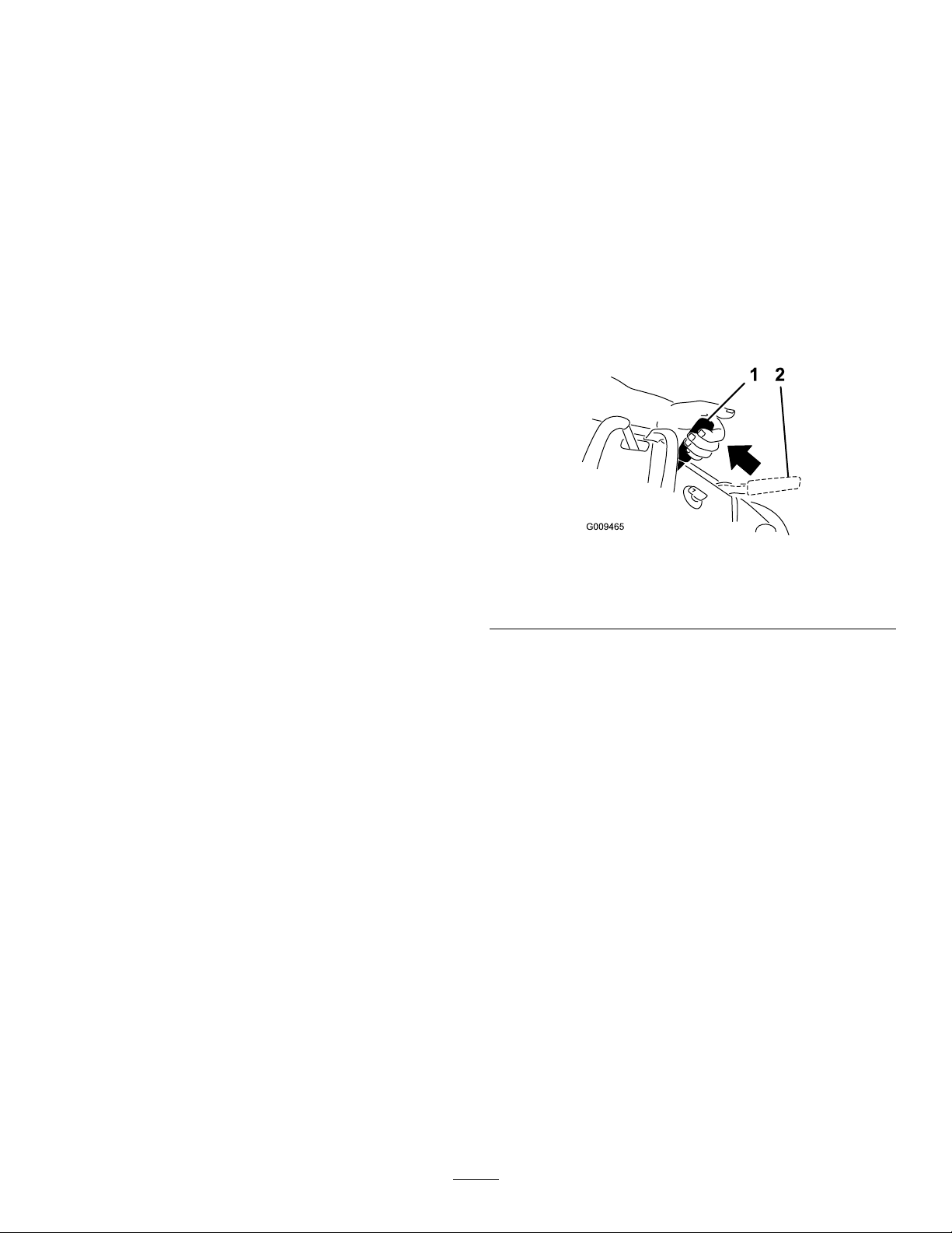
Pulltheparking-brakeleverrearwardtoengageit
(Figure8).
Pushtheparking-brakeleverforwardtodisengageit.
Note:Theengineshutsoffifyoumovethe
motion-controlleverswhiletheparkingbrakeis
engagedorifthemachineidlesfor5secondswhile
theparkingbrakeisdisengaged.
g009465
Figure8
1.Parkingbrake—engaged2.Parking
brake—disengaged
13
StartingtheEngine
Note:Ifyoureleasethemotion-controlleversanddonotengagetheparkingbrake,theenginewillshutoff
after5seconds.
ShuttingOfftheEngine
g292627
Figure9
g289750
Figure10
14
Operatingthe
Mower-Blade-Control
Switch(PTO)
Usetheblade-controlswitch(PTO)inconjunctionwith
themotion-controlleverstoengageanddisengage
themowerblades.
EngagingtheMowerBlades(PTO)
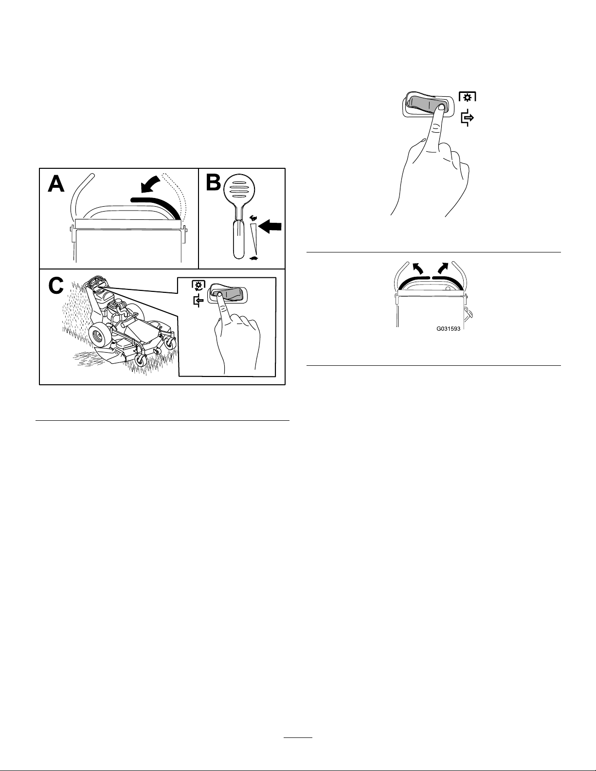
DisengagingtheMowerBlades
(PTO)
Figure12andFigure13show2waystodisengage
themowerblades.
g299432
Figure12
Figure11
g031593
Figure13
g299433
15
DrivingtheMachine
Thethrottlecontrolregulatestheenginespeedas
measuredinrpm(revolutionsperminute).Place
thethrottlecontrolintheFASTpositionforbest
performance.
Note:Theengineshutsoffifyoumovethe
motion-controlleverswhiletheparkingbrakeis
engagedorifthemachineidlesfor5secondswhile
theparkingbrakeisdisengaged.
CAUTION
Themachinecanspinveryrapidly,andyou
maylosecontrolofthemachine,causing
personalinjurytoyouanddamagetothe
machine.
Slowdownthemachinebeforemakingsharp
turns.
DrivingForward
1.Disengagetheparkingbrake;refertoOperating
theParkingBrake(page13).
Note:Thefartheryoumovethemotion-control
leversineitherdirection,thefasterthemachine
movesinthatdirection.
Note:T ostop,movethemotion-controllevers
backtotheNEUTRALposition.
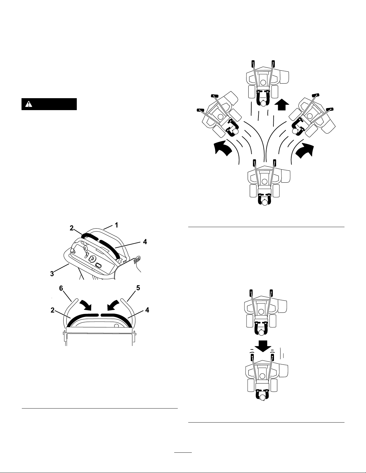
2.Movethemotion-controlleversdowntothe
NEUTRALposition.
Figure14
1.Frontreferencebar
2.Leftcontrolleverin
NEUTRALposition
3.Rearreferencebar6.Leftcontrolleverwhen
4.Rightcontrolleverin
NEUTRALposition
5.Rightcontrolleverwhen
released
released
3.Slowlypushthemotion-controlleversforward
(Figure15).
g303736
Figure15
DrivingBackward
1.Movebothmotion-controlleverstotheNEUTRAL
position.
2.Slowlypullthemotion-controlleversrearward
(Figure16).
g299431
g303735
Figure16
16

UsingtheAdjustable
ReferenceBar
Usetheadjustmentlevertochangethepositionof
theadjustablereferencebarandlimitthemaximum
forwardspeed(Figure17).
Movethelevertotheupperpositiontodecreasethe
maximumspeed;movethelevertothelowerposition
toincreasethemaximumspeed.
Figure17
SideDischargingor
g299434
MulchingGrass
Thismowerhasahingedgrassdeectorthat
dispersesclippingstothesideanddowntowardthe
turf.
DANGER
Withoutthegrassdeector,dischargecover,
orcompletegrasscatcherassemblymounted
inplace,youandbystandersareexposedto
bladecontactandthrowndebris.Contactwith
rotatingmowerblade(s)andthrowndebris
cancauseseriousinjuryordeath.
•Neverremovethegrassdeectorfromthe
mowerdeck,becausethegrassdeector
routesmaterialdowntowardtheturf.If
thegrassdeectorisdamaged,replaceit
immediately.
•Neverputyourhandsorfeetunderthe
mowerdeck.
•Nevertrytoclearthedischargeareaor
mowerbladesbeforeyoudisengagethe
mowerblades.Turntheignitionkeyto
theOFFposition.Removethekeyand
disconnectthespark-plugwires.
17

AdjustingtheHeightofCut
Youcanadjusttheheightofcutfrom38to114mm(1-1/2to4-1/2inches)in6mm(1/4inch)increments.
Figure18
g303747
18

AdjustingtheAnti-Scalp
Rollers
AfterOperation
Modelswitha122cm(48inch),
137cm(54inch),or152cm(60
inch)DeckOnly
Wheneveryouchangetheheight-of-cut,adjustthe
heightoftheanti-scalprollers.
1.Parkthemachineonalevelsurface,disengage
theblade-controlswitch,andengagetheparking
brake.
2.Shutofftheengine,removethekey,andwait
forallmovingpartstostopbeforeleavingthe
operatingposition.
3.Removethenutandboltpositiontheanti-scalp
rollersandinstallthenutandbolt.
4.Ensurethatthespacersandbushingsare
installed(Figure19).
AfterOperationSafety
GeneralSafety
•Alwaysshutoffthemachine,removetheignition
key(ifequipped),waitforallmovingpartstostop,
andallowthemachinetocoolbeforeadjusting,
servicing,cleaning,orstoringit.
•Cleangrassanddebrisfromthemachinetohelp
preventres.Cleanupoilorfuelspills.
•Neverstorethemachineorfuelcontainerwhere
thereisanopename,spark,orpilotlight,such
asonawaterheateroronotherappliances.
•Usefull-widthrampsforloadingthemachineinto
atrailerortruck.
•Tiethemachinedownsecurelyusingstraps,
chains,cable,orropes.Directbothfrontandrear
strapsdownandoutwardfromthemachine.
UsingtheFuel-Shutoff
Figure19
1.Bushing4.Bolt
2.Anti-scalproller5.Nut
3.Spacer
Valve
Closethefuel-shutoffvalvefortransport,maintenance,
andstorage(Figure20).
Ensurethatthefuel-shutoffvalveisopenwhen
startingtheengine.
g301976
g299483
Figure20
1.OFFposition2.ONposition
19

PushingtheMachineby
OperatingtheMachine
Hand
Important:Alwayspushthemachinebyhand.
Donottowthemachine,becausetowingmay
damageit.
Important:Donotstartoroperatethemachine
withthebypassvalvesopen.Damagetosystem
mayoccur.
PushingtheMachine
1.Parkthemachineonalevelsurface,disengage
theblade-controlswitch,andengagetheparking
brake.
2.Shutofftheengine,removethekey,andwait
forallmovingpartstostopbeforeleavingthe
operatingposition.
3.Locatethebypassleversontheframeonboth
sidesoftheengine.
4.Movethebypassleversrearwardthroughthe
keyholeanddowntolocktheminplace(Figure
21).
Note:Dothisforeachlever.
Movethebypassleversforwardthroughthekeyhole
anddowntolocktheminplaceasshowninFigure21.
Note:Dothisforeachlever.
TransportingtheMachine
Useaheavy-dutytrailerortrucktotransportthe
machine.Useafull-widthramp.Ensurethatthetrailer
ortruckhasallthenecessarybrakes,lighting,and
markingasrequiredbylaw.Pleasecarefullyreadall
thesafetyinstructions.Knowingthisinformationcould
helpyouorbystandersavoidinjury.Refertoyour
localordinancesfortrailerandtie-downrequirements.
WARNING
Drivingonthestreetorroadwaywithout
turnsignals,lights,reectivemarkings,ora
slow-moving-vehicleemblemisdangerous
andcanleadtoaccidents,causingpersonal
injury.
Donotdrivethemachineonapublicstreet
orroadway .
5.Disengagetheparkingbrake.
SelectingaTrailer
WARNING
Loadingamachineontoatrailerortruck
increasesthepossibilityoftip-overandcould
causeseriousinjuryordeath(Figure22).
•Useonlyafull-widthramp;donotuse
individualrampsforeachsideofthe
machine.
•Ensurethatthelengthoframpisatleast4
timesaslongastheheightofthetraileror
truckbedtotheground.
g303749
Figure21
1.Bypass-leverlocations
2.Leverpositionfor
operatingthemachine
6.Whennished,engagetheparkingbrake.
3.Leverpositionforpushing
themachine
20

Figure23
g299488
1.Full-widthrampinstowed
position
2.Rampisatleast4times
aslongastheheightof
thetrailerortruckbedto
theground
LoadingtheMachine
WARNING
Figure22
3.H=heightofthetraileror
truckbedtotheground
4.Trailer
1.Backthemachineupthe
ramp.
2.Walkthemachinedown
theramp.
5.Shutofftheengine,removethekey,andengage
theparkingbrake.
6.Tiedownthemachinenearthefrontcaster
wheelsandtherearbumperwithstraps,chains,
cable,orropes(Figure24).Refertolocal
g229507
regulationsfortie-downrequirements.
Loadingamachineontoatrailerortruck
increasesthepossibilityoftip-overandcould
causeseriousinjuryordeath.
•Useextremecautionwhenoperatinga
machineonaramp.
•Backthemachineuptherampandwalkit
forwarddowntheramp.
•Avoidsuddenaccelerationordeceleration
whiledrivingthemachineonarampas
thiscouldcausealossofcontrolora
tip-oversituation.
1.Ifusingatrailer,connectittothetowingvehicle
andconnectthesafetychains.
2.Ifapplicable,connectthetrailerbrakesand
lights.
3.Lowertheramp(Figure22).
4.Backthemachineuptheramp(Figure23).
1.Reartie-downloop
2.Fronttie-downloopfor
122,137,and152cm(48,
54,and60inch)machines
g328545
Figure24
3.Tiedownthefrontcaster
framefor91cm(36inch)
machines.
21

Maintenance
Note:Determinetheleftandrightsidesofthemachinefromthenormaloperatingposition.
MaintenanceSafety
•Beforeadjusting,cleaning,servicing,orleaving
themachine,dothefollowing:
–Parkthemachineonalevelsurface.
–Movethethrottleswitchtothelow-idleposition.
–Disengagethecuttingunits.
–Ensurethatthetransmissionisinneutral.
–Engagetheparkingbrake.
–Shutofftheengineandremovethekey .
–Waitforallmovingpartstostop.
–Allowmachinecomponentstocoolbefore
performingmaintenance.
•Donotallowuntrainedpersonneltoservicethe
machine.
•Iftheenginemustberunningtoperforma
maintenanceadjustment,keepyourhands,feet,
clothing,andanypartsofthebodyawayfromthe
RecommendedMaintenanceSchedule(s)
cuttingunit,attachments,andanymovingparts.
Keepbystandersaway.
•Keepallpartsingoodworkingcondition.Replace
allworn,damaged,ormissingpartsanddecals.
Keepallfastenerstighttoensurethatthemachine
isinsafeworkingcondition.
•Checkthegrasscatchercomponentsfrequently
andreplacethemwhentheyarewornordamaged.
•Cleangrassanddebrisfromthecuttingunit,
drives,mufer,coolingscreen,andtheengineto
helppreventres.Cleanupoilorfuelspills.
•Checkthebrakeoperationfrequently .Adjustand
servicethebrakeasneeded.
•Carefullyreleasepressurefromcomponentswith
storedenergy.
•T oensuresafe,optimalperformanceofthe
machine,useonlygenuineT ororeplacement
parts.Replacementpartsmadebyother
manufacturerscouldbedangerous,andsuchuse
couldvoidtheproductwarranty.
MaintenanceService
Interval
Aftertherst8hours
Aftertherst50hours
Aftertherst100hours
Beforeeachuseordaily
Every25hours
Every50hours
Every100hours
MaintenanceProcedure
•Changetheengineoil.
•Changethehydraulic-systemltersanduid.
•Checkthewheel-lugnuts.
•Checkthesafety-interlocksystem.
•Checktheengine-oillevel.
•Cleantheair-intakescreen.
•Cleanthegrassanddebrisfromtheair-intakescreen.
•Testtheparkingbrake.
•Inspecttheblades.
•Inspectthegrassdeectorfordamage.
•Cleanthemowerdeck.
•Greasethecasterwheelbearings.
•Cleanthefoamair-cleanerelement—standardaircleanersonly.
•Checkthebeltsforwearorcracks.
•Checkthepaperair-cleanerelement—standardaircleanersonly.
•Checkthehydraulicuid.
•Changetheengineoil.
•Check,cleanandgapthesparkplug.
•Checkthebattery.
•Checkandcleantheengine-coolingnsandshrouds.
Every200hours
•Replacethepaperair-cleanerelement—standardaircleanersonly.
•Changetheengine-oillter.
22

MaintenanceService
Every250hours
Interval
MaintenanceProcedure
•Replacetheprimaryairlter(moreoftenindirtyordustyconditions)—heavy-duty
aircleanersonly .
•Checkthesafetyairlter(moreoftenindirtyordustyconditions)—heavy-dutyair
cleanersonly.
Every300hours
Every500hours
Every800hours
Yearly
•Checkandadjustthevalveclearance.ContactanAuthorizedServiceDealer.
•Replacethesafetyairlter(moreoftenindirtyordustyconditions)—heavy-duty
aircleanersonly .
•Adjustthecaster-pivotbearing.
•Aftertheinitialchange—changethehydraulic-systemltersanduidwhenusing
Toro®HYPR-OIL™500uid.(Changeitmoreoftenunderdirtyordustyconditions)
•Replacethefuellter.
•Greasethefrontcasterpivots(moreoftenindirtyordustyconditions).
•Checkthemowerdeckidlerarmforwear.
•Inspectthebladeboltsandcurvedwashers.Replaceifdamaged.
Important:Refertoyourengineowner'smanualforadditionalmaintenanceprocedures.
CAUTION
Ifyouleavethekeyintheswitch,someonecouldaccidentlystarttheengineandseriously
injureyouorotherbystanders.
Shutofftheengineandremovethekeyfromtheswitchbeforeyouperformanymaintenance.
Pre-Maintenance
Procedures
RemovingtheMowerDeck
Guard
1.Parkthemachineonalevelsurface,disengage
theblade-controlswitch(PTO),andengagethe
parkingbrake.
2.Shutofftheengine,removethekey,andwait
forallmovingpartstostopbeforeleavingthe
operatingposition.
3.Unlatchthe2rubberlatchesfromthescrews
andremovethedeckcover(Figure25).
g302738
Figure25
23

Lubrication
GreasingtheCasterWheel
Bearings
GreasingtheMachine
Greasethemachinemoreoftenindirtyordusty
conditions.
GreaseType:No.2lithiumormolybdenumgrease
1.Parkthemachineonalevelsurface,disengage
theblade-controlswitch(PTO),andengagethe
parkingbrake.
2.Shutofftheengine,removethekey,andwait
forallmovingpartstostopbeforeleavingthe
operatingposition.
3.Cleanthegreasettingswitharag.
Note:Scrapeanypaintoffthefrontofthe
tting(s).
4.Pumpgreaseintothettingsuntilgreasebegins
tooozeoutofthebearings.
5.Wipeupanyexcessgrease.
GreasingtheFrontCaster
ServiceInterval:Every25hours—Greasethecaster
wheelbearings.
GreaseType:No.2lithiumgrease
1.Parkthemachineonalevelsurface,disengage
theblade-controlswitch,andengagetheparking
brake.
2.Shutofftheengine,removethekey,andwait
forallmovingpartstostopbeforeleavingthe
operatingposition.
3.Cleanthegreasettings(Figure26)witharag.
Note:Scrapeanypaintoffthefrontofthe
tting(s).
Pivots
ServiceInterval:Yearly
Greasetype:Lithiumormolybdenumgrease
1.Removethedustcapandadjustthecaster
pivots;refertoAdjustingtheCaster-Pivot
Bearings(page36).
Note:Keepthedustcapoffuntilyouhave
nishedgreasingthecasterpivots.
2.Removethehexplug.
3.Threadagreasettingintothehole.
4.Pumpgreaseintothettinguntilitoozesout
aroundthetopbearing.
5.Removethegreasettingfromthehole.
6.Installthehexpluganddustcap.
g301977
Figure26
1.Frontcastergreasetting
4.Connectagreaseguntoeachtting(Figure26).
5.Pumpgreaseintothettingsuntilgreasebegins
tooozeoutofthebearings.
6.Wipeupanyexcessgrease.
24

EngineMaintenance
EngineSafety
•Donotchangethegovernorspeedoroverspeed
theengine.
•Runtheenginedryorremovethefuelwithahand
pump;neversiphonthefuel.Ifyoumustdrainthe
fueltank,doitoutdoors.
ServicingtheAirCleaner
RefertoFigure27toidentifytheaircleanerforyour
engine.
4.Unscrewthecoverknobsandremovethe
air-cleanercover(Figure28).
5.Unscrewthehoseclampandremovethe
air-cleanerassembly(Figure28).
6.Carefullypullthefoamelementoffthepaper
element(Figure28).
g012619
Figure28
Figure27
1.Standardaircleaner
2.Heavy-dutyaircleaner
ServicingaStandardAirCleaner
ServiceInterval:Every25hours—Cleanthefoam
air-cleanerelement—standardair
cleanersonly.
Every50hours—Checkthepaperair-cleaner
element—standardaircleanersonly.
Every200hours—Replacethepaperair-cleaner
element—standardaircleanersonly.
Note:Servicetheaircleanermorefrequently(every
fewoperatinghours)iftheoperatingconditionsare
extremelydustyorsandy.
Important:Donotapplyoiltothefoamorpaper
element.
RemovingtheFoamandPaperElements
1.Parkthemachineonalevelsurface,disengage
thePTO,andengagetheparkingbrake.
2.Shutofftheengine,removethekey,andwait
forallmovingpartstostopbeforeleavingthe
operatingposition.
3.Cleantheareaaroundtheaircleanertoprevent
dirtfromenteringtheengineandcausing
damage(Figure28).
g302948
1.Cover
2.Hoseclamp4.Foamelement
3.Paperelement
CleaningtheFoamAir-CleanerElement
1.Washthefoamelementinliquidsoapand
warmwater.Whentheelementisclean,rinse
itthoroughly.
2.Drytheelementbysqueezingitinacleancloth.
Important:Replacethefoamelementifit
istornorworn.
ServicingthePaperAir-CleanerElement
Important:Donotcleanthepaperlter,replace
it(Figure28).
1.Inspecttheelementfortears,anoilylm,or
damagetotherubberseal.
2.Replacethepaperelementifitisdamaged.
InstallingtheFoamandPaperElements
Important:Topreventenginedamage,always
operatetheenginewiththecompletefoamand
paperair-cleanerassemblyinstalled.
1.Carefullyslidethefoamelementontothepaper
air-cleanerelement(Figure28).
2.Placetheair-cleanerassemblyontotheair
cleanerbaseandsecureitwiththe2wingnuts
(Figure28).
25

3.Placetheair-cleanercoverintopositionand
tightenthecoverknob(Figure28).
ServicingaHeavyDutyAirCleaner
ServiceInterval:Every250hours—Replacethe
primaryairlter(moreoftenindirty
ordustyconditions)—heavy-dutyair
cleanersonly.
Every250hours—Checkthesafety
airlter(moreoftenindirtyordusty
conditions)—heavy-dutyaircleanersonly.
Every500hours—Replacethesafety
airlter(moreoftenindirtyordusty
conditions)—heavy-dutyaircleanersonly.
Note:Servicetheaircleanermorefrequentlyif
operatingconditionsareextremelydustyorsandy .
RemovingtheFilters
1.Parkthemachineonalevelsurface,disengage
theblade-controlswitch(PTO),andengagethe
parkingbrake.
2.Shutofftheengine,removethekey,andwait
forallmovingpartstostopbeforeleavingthe
operatingposition.
3.Releasethelatchesontheaircleanerandpull
theair-cleanercoverofftheair-cleanerbody
(Figure29).
6.Removethesafetylteronlytoreplaceit.
InspectingtheFilters
1.Inspectthesafetylter.Ifitisdirty ,replaceboth
thesafetyandprimarylters.
Important:Donotattempttocleanthe
safetylter.Ifthesafetylterisdirty,then
theprimarylterisdamaged.
2.Inspecttheprimarylterfordamagebylooking
intothelterwhileshiningabrightlightonthe
outsideofthelter.Iftheprimarylterisdirty,
bent,ordamaged,replaceit.
Note:Holesinthelterappearasbrightspots.
Donotcleantheprimarylter.
InstallingtheFilters
Important:Topreventenginedamage,always
operatetheenginewithbothairltersandthe
coverinstalled.
1.Ifyouareinstallingnewlters,checkeachlter
forshippingdamage.
Note:Donotuseadamagedlter.
2.Ifyouarereplacingtheinnerlter,carefullyslide
itintothelterbody(Figure29).
3.Carefullyslidetheprimarylteroverthesafety
lter(Figure29).
Figure29
1.Air-cleanerbody4.Air-cleanercover
2.Primarylter5.Safetylter
3.Latch
4.Cleantheinsideoftheair-cleanercoverwith
compressedair.
5.Gentlyslidetheprimarylteroutofthe
air-cleanerbody(Figure29).
Note:Ensurethattheprimarylterisfully
seatedbypushingontheouterrimwhile
installingit.
Important:Donotpressonthesoft,inside
areaofthelter.
4.Installtheair-cleanercoverandsecurethe
latches(Figure29).
g001883
Note:Avoidknockingthelterintothesideof
thebody.
26

ServicingtheEngineOil
Engine-OilSpecications
CheckingtheEngine-OilLevel
ServiceInterval:Beforeeachuseordaily
Note:Checktheoilwhentheengineiscold.
Model44409,44410,44423,44424,and44427
OilType:Detergentoil(APIserviceSF,SG,SH,SJ,
orSL)
EngineOilCapacity:1.5L(51oz)withoutlter;
1.7L(57oz)withlter
Viscosity:Refertothetablebelow.
Figure30
WARNING
Contactwithhotsurfacesmaycausepersonal
injury.
Keepyourhands,feet,face,clothingand
otherbodypartsawaythemuferandother
hotsurfaces.
Important:Donotoverllthecrankcasewithoil
becausedamagetotheenginemayresult.Donot
runenginewithoilbelowthelowmarkbecause
theenginemaybedamaged.
1.Parkthemachineonalevelsurface,disengage
thePTO,andengagetheparkingbrake.
2.Shutofftheengine,removethekey,andwait
forallmovingpartstostopbeforeleavingthe
operatingposition.
3.Checktheengine-oillevelasshownin(Figure
g303164
32).
Model44430,44448,and44454
OilType:Detergentoil(APIserviceSF,SG,SH,SJ,
orSL)
EngineOilCapacity:1.8L(61oz)withoutlter;
2.0L(68oz)withlter
Viscosity:Refertothetablebelow.
Figure31
g037096
27

ChangingtheEngineOil
ServiceInterval:Aftertherst8hours
Every100hours
Note:Disposeoftheusedoilatarecyclingcenter.
1.Parkthemachinesothatthedrainsideisslightly
lowerthantheoppositesidetoassuretheoil
g299569
drainscompletely.
2.DisengagethePTOandengagetheparking
brake.
3.Shutofftheengine,removethekey,andwait
forallmovingpartstostopbeforeleavingthe
operatingposition.
4.ChangetheengineoilasshowninFigure33.
Figure32
g311705
28

g299570
g235264
Figure34
6.Starttheengineanddrivetoaatarea.
7.Checktheoillevelagain.
ChangingtheEngine-OilFilter
ServiceInterval:Every200hours
Figure33
5.Slowlypourapproximately80%ofthespecied
oilintothellertubeandslowlyaddthe
additionaloiltobringittotheFullmark(Figure
34).
Note:Changetheengine-oilltermorefrequently
whenoperatingconditionsareextremelydustyor
sandy.
1.Draintheoilfromtheengine;refertoChanging
theEngineOil(page28).
2.Changetheengine-oillter(Figure35).
g036784
29

ServicingtheSparkPlug
ServiceInterval:Every100hours
Ensurethattheairgapbetweenthecenterandside
electrodesiscorrectbeforeinstallingthesparkplug.
Useasparkplugwrenchforremovingandinstalling
thesparkplug(s)andagappingtool/feelergaugeto
g299569
checkandadjusttheairgap.Installanewspark
plug(s)ifnecessary.
Type:NGK®BPR4ESorequivalent
Airgap:0.75mm(0.03inch)
RemovingtheSparkPlug
1.Parkthemachineonalevelsurface,disengage
thePTO,andengagetheparkingbrake.
2.Shutofftheengine,removethekey,andwait
forallmovingpartstostopbeforeleavingthe
operatingposition.
3.RemovethesparkplugasshowninFigure36.
Figure35
Note:Ensurethattheoil-ltergaskettouches
theengine,thenrotatethelteranextra3/4turn.
3.Fillthecrankcasewiththepropertypeofnew
oil;refertoEngine-OilSpecications(page27).
g299598
g027477
g027478
Figure36
CheckingtheSparkPlug
Important:Donotcleanthesparkplug(s).
Alwaysreplacethesparkplug(s)whenithasa
blackcoating,wornelectrodes,anoilylm,or
cracks.
Ifyouseelightbrownorgrayontheinsulator,the
engineisoperatingproperly.Ablackcoatingonthe
insulatorusuallymeanstheaircleanerisdirty .
Setthegapto0.75mm(0.03inch).
30

Figure37
InstallingtheSparkPlug
FuelSystem
Maintenance
DANGER
Incertainconditions,fuelisextremely
g027479
ammableandhighlyexplosive.Areor
explosionfromfuelcanburnyouandothers
andcandamageproperty.
RefertoFuelSafety(page10)foracomplete
listoffuelrelatedprecautions.
DrainingtheFuelTank
Note:Useasyphonpumptodrainfuelfromthetank.
Youcanpurchaseasyphonpumpatahardwarestore.
DANGER
Incertainconditions,fuelisextremely
ammableandhighlyexplosive.Areor
explosionfromfuelcanburnyou,others,and
candamageproperty .
Figure38
•Performanyfuel-relatedmaintenance
whentheengineiscold.Dothisoutdoors
inanopenarea.Wipeupanyfuelthat
spills.
g027661
•Neversmokewhendrainingfuel,andstay
awayfromanopenameorwhereaspark
mayignitethefuelfumes.
1.Parkthemachineonalevelsurface,disengage
thePTO,andengagetheparkingbrake.
2.Shutofftheengine,removethekey,andwait
forallmovingpartstostopbeforeleavingthe
operatingposition.
3.Cleanaroundthefuelcaptopreventdebrisfrom
gettingintothefueltank(Figure39).
4.Removethefuelcap.
5.Insertasyphonpumpintothefueltank.
6.Usingthesyphonpump,drainthefuelintoa
cleanfuelcan(Figure39).
7.Wipeupanyspilledfuel.
31

Figure39
1.Fuelcap
ReplacingtheFuelFilter
ServiceInterval:Every800hours/Y early(whichever
comesrst)
Donotinstalladirtylterifitisremovedfromthefuel
line.
Note:Wipeupanyspilledfuel.
1.Parkthemachineonalevelsurface,disengage
thePTO,andengagetheparkingbrake.
2.Shutofftheengine,removethekey,andwait
forallmovingpartstostopbeforeleavingthe
operatingposition.
3.Closethefuel-shutoffvalve;refertoUsingthe
Fuel-ShutoffValve(page19).
4.ReplacethefuellterasshowninFigure40.
g300374
g029685
Figure40
32

ElectricalSystem
Maintenance
ElectricalSystemSafety
•Disconnectthebatterybeforerepairingthe
machine.Disconnectthenegativeterminalrst
andthepositivelast.Connectthepositiveterminal
rstandthenegativelast.
•Chargethebatteryinanopen,well-ventilated
area,awayfromsparksandames.Unplugthe
chargerbeforeconnectingordisconnectingthe
battery.Wearprotectiveclothinganduseinsulated
tools.
ServicingtheBattery
ServiceInterval:Every100hours
Alwayskeepthebatterycleanandfullycharged.Use
apapertoweltocleanthebatterycase.Ifthebattery
terminalsarecorroded,cleanthemwithasolutionof
fourpartswaterand1partbakingsoda.Applyalight
coatingofgreasetothebatteryterminalstoprevent
corrosion.
WARNING
Incorrectlyremovingthecablesfrom
batterycoulddamagethemachineand
cables,causingsparks.Sparkscan
causethebatterygassestoexplode,
resultinginpersonalinjury.
•Alwaysdisconnectthenegative
(black)batterycablebefore
disconnectingthepositive(red)
cable.
•Alwaysconnectthepositive(red)
batterycablebeforeconnectingthe
negative(black)cable.
4.Slidetherubbercoveroffthepositive(red)
cable.
5.Disconnectthepositive(red)cablefromthe
batterypost(Figure41).
Note:Retainallfasteners.
6.Removethebatteryhold-down(Figure41),and
liftthebatteryfromthetray.
Voltage:12V
RemovingtheBattery
1.Parkthemachineonalevelsurface,disengage
thePTO,andengagetheparkingbrake.
2.Shutofftheengine,removethekey,andwait
forallmovingpartstostopbeforeleavingthe
operatingposition.
3.Disconnectthenegative(black)groundcable
fromthebatterypost(Figure41).
Note:Retainallfasteners.
WARNING
Batteryterminalsormetaltools
couldshortagainstmetalmachine
components,causingsparks.Sparks
cancausethebatterygassestoexplode,
resultinginpersonalinjury.
•Whenremovingorinstallingthe
battery,donotallowthebattery
terminalstotouchanymetalpartsof
themachine.
g299658
Figure41
1.Battery4.Terminalboot
2.Positive(+)batterypost5.Negative(–)batterypost
3.Bolt,washer,andnut6.Batteryhold-down
•Donotallowmetaltoolstoshort
betweenthebatteryterminalsand
metalpartsofthemachine.
33

ChargingtheBattery
ServicingtheFuses
WARNING
Chargingthebatteryproducesgassesthat
canexplode.
Neversmokenearthebatteryandkeepsparks
andamesawayfrombattery.
Important:Alwayskeepthebatteryfullycharged
(1.260specicgravity).Thisisespecially
importanttopreventbatterydamagewhenthe
temperatureisbelow0°C(32°F).
1.Removethebatteryfromthemachine;referto
RemovingtheBattery(page33).
2.Connecta3to4Abatterychargertothebattery
posts.Chargethebatteryatarateof3to4A
for4to8hours(12V).
Note:Donotoverchargethebattery.
3.Whenthebatteryisfullycharged,unplugthe
chargerfromtheelectricaloutlet,anddisconnect
thechargerleadsfromthebatteryposts(Figure
42).
4.Installthebattery;refertoInstallingtheBattery
(page34).
Theelectricalsystemisprotectedbyfuses.Itrequires
nomaintenance;however,ifafuseblows,checkthe
component/circuitforamalfunctionorshort.
1.Parkthemachineonalevelsurface,disengage
thePTO,andengagetheparkingbrake.
2.Shutofftheengine,removethekey,andwait
forallmovingpartstostopbeforeleavingthe
operatingposition.
3.Pulloutthefusetoremoveorreplaceit.
Figure42
1.Positivebatterypost
2.Negativebatterypost
3.Red(+)chargerlead
4.Black(-)chargerlead
InstallingtheBattery
1.Positionthebatteryinthetray(Figure41).
2.Usingthefastenerspreviouslyremoved,install
thepositive(red)batterycabletothepositive
(+)batteryterminal.
3.Usingthefastenerspreviouslyremoved,install
thenegativebatterycabletothenegative(-)
batteryterminal.
4.Slidetheredterminalbootontothepositive
(red)batterypost.
5.Securethebatterywiththehold-down(Figure
41).
g299668
Figure43
1.Mainfuse(15A)2.Chargingfuse(25A)
g000538
34

DriveSystem
Maintenance
CheckingtheTirePressure
Figure44
g300244
g300245
Figure45
1.Nut2.Lowercontrolrod
5.Startthemachineandmovethethrottlecontrol
totheFASTposition.
6.Tondtheneutralposition,movethelower
g300243
controlrodupordownuntilthetirestopsrotating
(Figure45).
7.Tightenthenut(Figure45).
CheckingtheWheel-Lug
Nuts
ServiceInterval:Aftertherst100hours—Checkthe
wheel-lugnuts.
Checkandtorquethewheel-lugnutsto115to142
N∙m(85to105ft-lb).
AdjustingtheNeutral
Traction
Ifthemachinecreepswhilethemotion-controllevers
areinneutral,adjusttheneutraltraction.
1.Parkthemachineonalevelsurface,disengage
thePTO,andengagetheparkingbrake.
2.Shutofftheengine,removethekey,andwait
forallmovingpartstostopbeforeleavingthe
operatingposition.
3.Raisetherearofthemachineontojackstands
highenoughtoraisethedrivewheelsoffthe
ground.
4.Loosenthenutforcontrol-rodassembly(Figure
45).
Important:Ensurethattheroddoesnot
move;otherwise,youmayneedtoadjustthe
rodagain.
8.Repeatfortheotherlever.
Note:Y oumayneedtoadjustthetrackingafter
adjustingtheneutraltraction;refertoAdjustingthe
Tracking(page35).
AdjustingtheTracking
Ifyoupushbothmotion-controlleversforwardfull
speedacrossaat,levelsurfaceandthemachine
pullsto1side,adjustthetrackingasfollows.
1.Parkthemachineonalevelsurface,disengage
thePTO,andengagetheparkingbrake.
2.Shutofftheengine,removethekey,andwait
forallmovingpartstostopbeforeleavingthe
operatingposition.
3.RotatetheadjustmentscrewshowninFigure45
toincreaseordecreasethespeedforthatlever.
Note:Rotatethescrewclockwisetodecrease
thespeed;rotateitcounterclockwisetoincrease
thespeed.
Ifthemachinepullstotheleft,decreasethe
speedfortherightleverorincreasethespeed
fortheleftlever.
35

Ifthemachinepullstotheright,decreasethe
speedfortheleftleverorincreasethespeed
fortherightlever.
4.Tightenthelocknutuntilthespringwashersare
at,andthenbackoffa1/4turntoproperlyset
thepreloadonthebearings(Figure47).
Important:Makesurethatthespring
washersareinstalledcorrectlyasshownin
Figure47.
5.Installthedustcap(Figure47).
Figure46
1.Adjustmentscrew
4.Startthemachineanddriveforwardacrossa
at,levelsurfacewiththemotion-controllevers
fullyforwardtocheckifthemachinetracks
straight.Repeattheprocedureasneeded.
AdjustingtheCaster-Pivot
Bearings
122cm(48inch),137cm(54inch),
and152cm(60inch)Machines
Only
ServiceInterval:Every500hours/Y early(whichever
comesrst)
Note:Youdonotneedtoadjustthecaster-pivot
bearingsfor91cm(36inch)machines.
g299908
g001297
Figure47
1.Springwashers
2.Locknut
3.Dustcap
ServicingtheCaster
WheelsandBearings
Thecasterwheelsrotateonarollerbearingsupported
byaspannerbushing.Ifthebearingiskeptwell
lubricated,wearwillbeminimal.Failuretokeepthe
bearingwelllubricatedcausesrapidwear.Awobbly
casterwheelusuallyindicatesawornbearing.
1.Removethelocknutandwheelboltholdingthe
casterwheeltothecasterfork(Figure48).
1.Parkthemachineonalevelsurface,disengage
theblade-controlswitch,andengagetheparking
brake.
2.Shutofftheengine,removethekey,andwait
forallmovingpartstostopbeforeleavingthe
operatingposition.
3.Removethedustcapfromthecasterandtighten
thelocknut(Figure47).
36

Figure48
1.Locknut4.Rollerbearing
2.Bushing
3.Spannerbushing
2.Remove1bushing,thenpullthespanner
bushingandrollerbearingoutofthewheelhub
(Figure48).
3.Removetheotherbushingfromthewheelhub
andcleananygreaseanddirtfromthewheel
hub(Figure48).
4.Inspecttherollerbearing,bushings,spanner
bushingandtheinsideofthewheelhubforwear.
5.Casterwheel
6.Wheelbolt
Note:Replaceanydamagedorwornparts
(Figure48).
5.Place1bushingintothewheelhub(Figure48).
6.Greasetherollerbearingandspannerbushing,
andslidethemintothewheelhub(Figure48).
CoolingSystem
Maintenance
CleaningtheAir-Intake
Screen
Removeanybuildupofgrass,dirt,orotherdebris
fromthecylinderandcylinderheadcoolingns,
theair-intakescreenontheywheelend,andthe
carburetor-governorleversandlinkage.Thishelps
ensureadequatecoolingandcorrectenginespeedto
reducethepossibilityofoverheatingormechanical
damagetotheengine.
g009453
CleaningtheCooling
System
ServiceInterval:Beforeeachuseordaily
Every100hours/Yearly(whichevercomesrst)
1.Parkthemachineonalevelsurface,disengage
thePTO,andengagetheparkingbrake.
2.Shutofftheengine,removethekey,andwait
forallmovingpartstostopbeforeleavingthe
operatingposition.
3.Removetheair-intakescreen,recoilstarter,and
fanhousing(Figure49).
4.Cleanthedebrisandgrassfromtheengine
parts.
5.Installtheair-intakescreen,recoilstarter,and
fanhousing(Figure49).
7.Placethesecondbushingintothewheelhub
(Figure48).
8.Installthecasterwheelintothecasterforkand
secureitwiththewheelboltandlocknut(Figure
48).
9.Tightenthelocknutuntilthespannerbushing
bottomsagainsttheinsideofthecasterforks
(Figure48).
10.Greasethettingonthecasterwheel.
37

Figure49
1.Air-intakescreen4.Bolt
2.Fanhousing5.Nut
3.Recoilstarter
BrakeMaintenance
TestingtheParkingBrake
ServiceInterval:Beforeeachuseordaily
Beforeeachuse,testtheparkingbrakeonbotha
levelsurfaceandslope.
Alwaysengagetheparkingbrakewhenyoustopthe
machineorleaveitunattended.Iftheparkingbrake
doesnotholdsecurely ,adjustit.
1.DisengagethePTOandengagetheparking
brake
2.Shutofftheengine,removethekey,andwait
forallmovingpartstostopbeforeleavingthe
operatingposition.
g001472
3.Disengagetheparkingbrake.
4.Engagethebrakeleverandensurethatthe
machinedoesnotmove.
5.Adjustthebrakeifneeded.
AdjustingtheParking
Brake
1.Parkthemachineonalevelsurfaceand
disengagethePTO.
2.Shutofftheengine,removethekey,andwait
forallmovingpartstostopbeforeleavingthe
operatingposition.
3.Releasetheparkingbrake.
4.Loosentheboltonthecableclampontheleft
sideofthemachine(Figure50).
Figure50
1.Cable
2.Cableclamp
5.Pulldownonthecablesuntiltheyaretight.
6.Tightenthenut.
38
3.Boltandnut
g031396

7.Checktheparkingbrakefunction;referto
TestingtheParkingBrake(page38).
BeltMaintenance
InspectingtheBelts
ServiceInterval:Every25hours—Checkthebelts
forwearorcracks.
Replacethebeltifitisworn.Thesignsofawornbelt
includesquealingwhilethebeltisrotating;theblades
slippingwhilecuttinggrass;andfrayededges,burn
marks,andcracksonthebelt.
ReplacingtheMower-Deck
Belt
WARNING
Thespringisundertensionwheninstalled
andcancausepersonalinjury.
Becarefulwhenremovingthebelt.
1.Parkthemachineonalevelsurface,disengage
thePTO,andengagetheparkingbrake.
2.Shutofftheengine,removethekey,andwait
forallmovingpartstostopbeforeleavingthe
operatingposition.
3.For91cm(36-inch)decks,loosenthe2bolts
forbothpulleycoversandslidethecoversoff
(Figure51).
Figure51
g303050
1.Cover2.Screw(2)
4.For122cm(48-inch),137cm(54-inch),and
152cm(60-inch)decks,loosenthe4screws
forbothpulleycoversandremovethecovers
(Figure52).
39

Figure54
48in,54in,and60inMowerDecks
g299742
Figure52
1.Cover2.Screw(4)
5.Usingaspring-removaltool(T oroPartNo.
92-5771),removetheidlerspringfromthedeck
hooktoremovetensionontheidlerpulley,and
rollthebeltoffthepulleys(Figure53orFigure
54).
g298962
1.Idlerpulley
2.Clutchpulley5.Spring-removaltool
3.Mowerbelt
4.Spring
6.Routethenewbeltaroundtheclutchpulleyand
mowerpulleys(Figure53orFigure54).
7.Installtheidlerspringtothedeckhook(Figure
53orFigure54).
8.Checkthelengthofthespring.Ifitislessthan
15.2cm(6inches),adjusttheidlerpulleyarm;
proceedtostep4inAdjustingtheIdlerPulley
Arm(page41).
9.Installthepulleycovers(Figure51orFigure52).
Figure53
36inMowerDecks
1.Idlerpulley
2.Clutchpulley5.Spring-removaltool
3.Mowerbelt
4.Spring
g299741
40

AdjustingtheIdlerPulley
Arm
ServiceInterval:Yearly—Checkthemowerdeck
idlerarmforwear.
Ifthelengthofthespringislessthan15.2cm(6
inches)oriftheidlerpulleyarmcontactstheidlerstop
showninFigure55,adjusttheidlerpulleyarm.
g302008
Figure56
122cm(48-inch)deckshown
Figure55
122cm(48-inch)deckshown
1.Springlengthatleast15.2
cm(6inches)
2.Nut4.Idlerstop
1.Parkthemachineonalevelsurface,disengage
thePTO,andengagetheparkingbrake.
2.Shutofftheengine,removethekey,andwait
forallmovingpartstostopbeforeleavingthe
operatingposition.
3.Removethedeckguards;refertoRemovingthe
MowerDeckGuard(page23)
4.Loosenthenutontheidlerpulley(Figure55).
5.Adjustthepulleyintheslotasneeded(Figure
56).
3.Idlerpulley
1.Idlerarm
2.Slot4.Slidepulleytotherightfor
g302009
6.Tightenthenut(Figure55).
7.Installthedeckguard;refertoRemovingthe
MowerDeckGuard(page23).
3.Slidepulleytotheleftfor
wornbelt.
newbelt
ReplacingtheTransmission
Belt
1.Parkthemachineonalevelsurface,disengage
thePTO,andengagetheparkingbrake.
2.Shutofftheengine,removethekey,andwait
forallmovingpartstostopbeforeleavingthe
operatingposition.
3.Removethemower-deckbeltfromtheclutch
pulley;refertoReplacingtheMower-DeckBelt
(page39).
4.Removetheclutchpulley(Figure57).
Slidethepulleytotheleftoftheslotforaworn
beltorifthespringlengthismorethan15.2cm
(6inches).
Slidethepulleytotherightoftheslotforanew
beltorifthespringlengthislessthan15.2cm
(6inches)
41

1.Clutchpulley
2.Washer
Figure57
g300384
Figure59
1.Belt2.Idlerpulley
g300383
9.Installthespringtothespringanchor.Usethe
3.Bolt
driveratchettoapplytensiontothespringto
allowthebelttopassoverthelipoftheidler
pulley(Figure58).
5.Insertadriveratchetinthesquareholeofthe
idlerarmtoreleasethebelttension(Figure58).
Figure58
1.Spring3.Squarehole
2.Idlerpulley
6.Removethebelt(Figure59).
7.Slowlyreleasethedrivertoreleasethespring
tension.Removethespringfromtheanchoron
theframe,ifneeded.
8.Installthenewbelt,routingitaroundthepulleys
asshowninFigure59.
10.Releasethetensioninthespringtoapply
tensiontothebelt.
11.Checkthatthebeltisseatedproperlyinallthe
pulleys.
12.Installtheclutchpulley(Figure57).T orquethe
boltto68to81N∙m(50to60ft-lb).
13.Installthemower-deckbelttotheclutchpulley;
refertoReplacingtheMower-DeckBelt(page
39).
g303781
42

ControlsSystem
Maintenance
Adjustingthe
Motion-ControlLevers
Ifthemotion-controlleversdonotalignhorizontally ,
adjustthemotion-controllevers.
1.Parkthemachineonalevelsurface,disengage
thePTO,andengagetheparkingbrake.
2.Shutofftheengine,removethekey,andwait
forallmovingpartstostopbeforeleavingthe
operatingposition.
3.Pushthemotion-controlleversdowntothe
operatingposition.
g303793
Figure61
1.Nut3.Bailswitch
2.Cam4.Theatofthecam.
6.Adjustthecamuntilitalignswiththeother
motion-controlleverandtightenthenutforthe
cam(Figure61).
Figure60
1.Leftmotion-controlleverin
operatingposition
2.Rightmotion-controllever
inneutralposition
4.Checkthehorizontalalignmentofthe
motion-controllevers(Figure60).
5.Loosenthenutholdingthecamforthe
motion-controlleveryouareadjusting(Figure
61).
3.Checkthehorizontal
alignmenthere.
4.Rightmotion-controllever
inoperatingposition
Note:Movingthecamclockwiselowersthe
lever;movingthecamcounterclockwiseraises
g300386
thelever.
Important:Donotrotatetheatofthecam
pastvertical.Theoperator-presencecontrol
switchshouldnevercontacttheatofthe
cam(Figure61).
43

HydraulicSystem
Maintenance
HydraulicSystemSafety
•Seekimmediatemedicalattentionifuidisinjected
intoskin.Injecteduidmustbesurgicallyremoved
withinafewhoursbyadoctor.
•Ensurethatallhydraulic-uidhosesandlinesare
ingoodconditionandallhydraulicconnections
andttingsaretightbeforeapplyingpressureto
thehydraulicsystem.
•Keepyourbodyandhandsawayfrompinhole
leaksornozzlesthatejecthigh-pressurehydraulic
uid.
•Usecardboardorpapertondhydraulicleaks.
•Safelyrelieveallpressureinthehydraulicsystem
beforeperforminganyworkonthehydraulic
system.
HydraulicSystem
Specications
HydraulicFluidType:T oro®HYPR-OIL™500
hydraulicuid
HydraulicSystemFluidCapacity:4.7L(159oz)
Important:Usetheuidspecied.Otheruids
coulddamagethesystem.
CheckingtheHydraulic
FluidLevel
ServiceInterval:Every50hours
1.Parkthemachineonalevelsurface,disengage
thePTO,andengagetheparkingbrake.
2.Shutofftheengine,removethekey,andwait
forallmovingpartstostopbeforeleavingthe
operatingposition.
3.Allthemachinetocoolcompletely.
4.Checktheuidlevelonthesideofthehydraulic
tank(Figure62).Continuetheprocedureifthe
levelisbelowthecoldlllevel.
Figure62
ChangingtheHydraulic
FluidandFilters
ServiceInterval:Aftertherst50hours—Changethe
hydraulic-systemltersanduid.
Every500hours—Aftertheinitial
change—changethehydraulic-system
ltersanduidwhenusingT oro
500uid.(Changeitmoreoftenunderdirtyor
dustyconditions)
Toreplacethehydraulicuid,theltersneedtobe
removed.Replacebothatthesametime;referto
HydraulicSystemSpecications(page44)foruid
specications.
®
HYPR-OIL
g300398
™
5.Cleantheareaaroundthecapofthehydraulic
tank(Figure62).
6.Removethecapfromthellerneckandadd
uidtothereservoiruntilitreachesthecoldll
level(Figure62).
7.Installthecaponthetank(Figure62).
RemovingtheFiltersandDraining
theFluid
1.Parkthemachineonalevelsurface,disengage
theblade-controlswitch(PTO),andengagethe
parkingbrake.
44

2.Shutofftheengine,removethekey,andwait
forallmovingpartstostopbeforeleavingthe
operatingposition.
Important:Donotallowdirttoenterthe
hydraulicsystem,orcontaminationmay
occur.
3.Allowtheenginetocool.
4.Removethe2boltsandnutsfromthetransaxle
guards(Figure63).
Figure63
1.Shortcarriagebolt
2.Nut(5/16inch)
3.Transaxleguard
5.Pivottheguardsdown.
6.Locatethelterandguardsoneach
transaxle-drivesystem(Figure64).
9.Placeadrainpanbelowtheltertocatchthe
uidthatdrainswhenthelterandventplugs
areremoved.
10.Locateandremovetheventplugoneach
transmission
11.Unscrewtheltertoremoveit,andallowthe
uidtodrainfromthedrivesystem.
12.Repeatthisprocedureforbothlters.
InstallingtheHydraulicFilters
1.Applyathincoatofhydraulicuidonthesurface
oftherubbersealofeachlter.
g303851
2.Turnthelterclockwiseuntiltherubberseal
contactsthelteradapter,thentightenthelter
anadditional3/4to1fullturn.
7.Removethe3screwssecuringthelterguard
andremovetheguard(Figure64).
Figure64
Rightsideshown
1.Transaxledrive
2.Filter5.Ventplug
3.Filterguard
4.Screws
8.Carefullycleantheareaaroundthelters.
g010254
g027477
Figure65
3.Repeatfortheoppositelter.
4.Installthelterguardsovereachlterthatyou
previouslyremoved(Figure64).
5.Usethe3screwstosecurethelterguards
(Figure64).
45

AddingHydraulicFluid
1.Verifythattheventplugsareremovedbefore
addingtheuid.
2.Slowlypourthespecieduidthroughthe
expansionreservoiruntiluidcomesoutof1of
thevent-plugholes;refertoHydraulicSystem
Specications(page44).
3.Installtheventplug(Figure64).
4.Torquetheplugto20N∙m(15ft-lb).
5.Continuetoadduidthroughtheexpansion
reservoiruntiluidcomesoutoftheremaining
vent-plugholeonthesecondtransmission.
6.Installtheoppositeventplug.
7.Torquetheplugto20N∙m(15ft-lb).
8.Pivotthetransaxleguardsupandsecureboth
with2boltsand2nuts(Figure63).
9.Continuetoadduidthroughtheexpansion
reservoiruntilitreachestheFULLCOLDlineon
theexpansionreservoir.
10.ProceedtoBleedingtheHydraulicSystem
(page46).
1.Bypass-leverlocations
2.Leverpositionfor
operatingthemachine
g303749
Figure66
3.Leverpositionforbleeding
thetransmission
Important:Failuretobleedthehydraulic
systemafterchangingthehydrauliclters
anduidcanresultinirreparabledamageto
thetransaxledrivesystem.
BleedingtheHydraulic
System
1.Parkthemachineonalevelsurface,disengage
thePTO,andengagetheparkingbrake.
2.Shutofftheengine,removethekey,andwait
forallmovingpartstostopbeforeleavingthe
operatingposition.
3.Raisetherearofthemachineontojackstands
highenoughtoraisethedrivewheelsoffthe
ground.
4.Movebothbypassleversrearwardthroughthe
keyholeanddowntolocktheminplace(Figure
66).
5.Starttheengineandmovethethrottlecontrol
tohalfthrottle.
6.Slowlymovethemotion-controlleversbetween
thefullforwardandfullreversepositions5times.
7.Shutofftheengineandmovethebypasslevers
forwardthroughthekeyholeanddowntolock
theminplace(Figure66).
8.Starttheengine.
9.Slowlymovethemotion-controlleversbetween
thefullforwardandfullreversepositions5times.
10.Shutofftheengineandcheckthehydraulicuid
levelasitdrops,andadduidasrequiredto
maintaintheproperlevel.
11.Repeattheprocedureuntilairiscompletely
purgedfromthesystem.
Note:Airispurgedfromthesystemwhen
thetransaxleoperatesatnormalnoiselevels
andmovessmoothlyforwardandinreverseat
normalspeeds.
12.Checkthehydraulicuidlevelintheexpansion
reservoiranaltime,andadduidasrequired.
46

MowerDeck
Maintenance
BladeSafety
Awornordamagedbladecanbreakandapiece
couldbethrowntowardyouorbystanders,resulting
inseriouspersonalinjuryordeath.
•Inspectthebladesperiodicallyforexcessivewear
ordamage.
•Usecarewhencheckingtheblades.Weargloves
andusecautionwhenservicingthem.Only
replacetheblades;neverstraightenorweldthem.
•Onmulti-bladedmachines,takecareasrotating1
bladecancauseotherbladestorotate.
g006530
Figure67
1.Cuttingedge3.Wear/slotforming
2.Curvedarea4.Crack
CheckingforBentBlades
1.Rotatethebladesuntiltheendsfaceforward
andbackward.
ServicingtheCutting
Blades
BeforeInspectingorServicingthe
Blades
1.Parkthemachineonalevelsurface,disengage
thePTO,andengagetheparkingbrake.
2.Shutofftheengine,removethekey,and
disconnectthespark-plugwiresfromthespark
plugs.
InspectingtheBlades
ServiceInterval:Beforeeachuseordaily
1.Inspectthecuttingedges(Figure67).
2.Iftheedgesarenotsharporhavenicks,remove
andsharpentheblade;refertoSharpeningthe
Blades(page48).
3.Inspecttheblades,especiallyinthecurvedarea.
4.Ifyounoticeanycracks,wear,oraslotforming
inthisarea,immediatelyinstallanewblade
(Figure67).
2.Measurefromalevelsurfacetothecutting
edge,positionA,oftheblades(Figure68).
Figure68
1.Measureherefromblade
tohardsurface
3.Rotatetheoppositeendsofthebladesforward.
4.Measurefromalevelsurfacetothecuttingedge
ofthebladesatthesamepositionasinstep2
above.
2.PositionA
g000975
Note:Thedifferencebetweenthedimensions
obtainedinsteps2and3mustnotexceed3mm
(1/8inch).
Note:Ifthisdimensionexceeds3mm
(1/8inch),replacetheblade.
47

WARNING
Abladethatisbentordamagedcould
breakapartandcouldcriticallyinjure
youorbystanders.
•Alwaysreplaceabentordamaged
bladewithanewblade.
•Donotleorcreatesharpnotchesin
theedgesorsurfacesoftheblade.
g000552
Figure70
1.Sharpenatoriginalangle.
2.Checkthebalanceofthebladebyputtingitona
bladebalancer(Figure71).
RemovingtheBlades
Replacethebladeifabladehitsasolidobject,isout
ofbalance,orisbent.Forbestperformanceand
continuedsafetyconformanceofthemachine,use
genuineTororeplacementblades.Replacement
bladesmadebyothermanufacturersmayresultin
non-conformancewithsafetystandards.
1.Holdthebladeendusingaragorthicklypadded
glove.
2.Removethebladebolt,curvedwasher,and
bladefromthespindleshaft(Figure69).
Note:Ifthebladestaysinahorizontalposition,
thebladeisbalancedandcanbeused.
Note:Ifthebladeisnotbalanced,lesome
metalofftheendofthesailareaonly(Figure70).
g000553
Figure71
1.Blade2.Balancer
3.Repeatthisprocedureuntilthebladeis
balanced.
InstallingtheBlades
ServiceInterval:Yearly
1.Inspectthebladeboltfordamagedthreads.
Replacetheboltandcurvedwasheras
necessary.
Figure69
1.Sailareaoftheblade3.Curvedwasher
2.Blade4.Bladebolt
SharpeningtheBlades
1.Usealetosharpenthecuttingedgeatboth
endsoftheblade(Figure70).
Note:Maintaintheoriginalangle.
Note:Thebladeretainsitsbalanceifthesame
amountofmaterialisremovedfrombothcutting
edges.
2.Installthebladeontothespindleshaft(Figure
72).
Important:Thecurvedpartoftheblade
mustbepointingupwardtowardtheinside
ofthedecktoensurepropercutting.
g010341
3.Installthecurvedwasherandbladebolt(Figure
72).
Note:Thecurvedwasherconemustbe
installedtowardthebolthead(Figure72).
4.Torquethebladeboltto1 15to150N∙m(85to
110ft-lb).
48

Figure73
g006888
Figure72
1.Sailareaoftheblade3.Curvedwasher
2.Blade4.Bladebolt
LevelingtheMowerDeck
PreparingtheMachine
Ensurethatthemowerdeckislevelanytimeyou
installthemowerdeckorwhenyouseeanuneven
cutonyourlawn.
Levelthemowerdecksidetosidebeforeadjusting
thefront-to-rearslope.
1.Parkthemachineonalevelsurface,disengage
thePTO,andengagetheparkingbrake.
2.Shutofftheengine,removethekey,and
disconnectthespark-plugwiresfromthespark
plugs.
g004536
1.Measurefromalevel
surface
2.Measurethebladeat
pointsBandC
3.ThedifferencebetweenmeasurementsBandC
shouldbenomorethan6mm(1/4inch).
Note:Ifitisnotcorrect,refertoLevelingthe
MowerDeck(page50).
CheckingtheMowerDeck
Front-to-RearPitch
1.Adjustthetirepressureinthereartirestothe
correctspecications.
2.Position1bladefront-to-rear.MeasureatAand
Blocationsfromalevelsurfacetothecutting
edgeofthebladetips(Figure74).
Note:Themowerbladeshouldbe6mm(1/4
inch)lowerinfrontatAthanintherearatB.
3.Rotatethebladesandrepeatforotherblades.
3.Checkthetirepressureofbothdrivetires;refer
toCheckingtheTirePressure(page35).
4.Checkthemowerdeckforbentblades;remove
andreplaceanybentblades;refertoServicing
theCuttingBlades(page47).
5.Lowerthemowerdecktothe76mm(3inch)
height-of-cutposition.
CheckingtheSide-to-SideLevel
1.Positionthebladessidetoside.
2.MeasureattheBandClocationsfromalevel
surfacetothecuttingedgeofbladetips(Figure
73).
1.Measurethebladeat
pointsAandB
49
g001041
Figure74
2.Measurefromalevel
surface

4.Ifthefront-to-rearpitchisnotcorrect,referto
LevelingtheMowerDeck(page49).
LevelingtheMowerDeck
1.Parkthemachineonalevelsurface,disengage
thePTO,andengagetheparkingbrake.
2.Shutofftheengine,removethekey,andwait
forallmovingpartstostopbeforeleavingthe
operatingposition.
3.Settheheight-of-cutlevertothe76mm(3inch)
position;refertoAdjustingtheHeightofCut
(page18)
4.Place2blocks,eachhavingathicknessof6.6
cm(2-5/8inches),undereachsideofthefront
edgeofthedeckbutnotundertheanti-scalp
rollerbrackets(Figure75).
5.Place2blocks,eachhavingathicknessof7.3
cm(2-7/8inches),undertherearedgeofthe
cuttingdeckskirt,1oneachsideofthecutting
deck(Figure75).
g300452
Figure76
1.Adjustmentbolt
7.Ensurethatthechainsaretautandtightenthe
bolts.
Figure75
122cm(48-inch)DeckShown
1.Woodblock—6.6cm
(2-5/8inches)thick
2.Woodblock—7.3cm
(2-7/8inches)thick
6.Loosentheadjustmentboltsonall4corners
ofthedecksothatthedeckissittingonall4
blocks.
3.Frontedge
8.Checktheside-to-sidelevelandthefront-to-rear
pitch;refertoCheckingtheSide-to-SideLevel
(page49)andCheckingtheMowerDeck
Front-to-RearPitch(page49).
ReplacingtheGrass
Deector
g303116
ServiceInterval:Beforeeachuseordaily—Inspect
thegrassdeectorfordamage.
WARNING
Anuncovereddischargeopeningcouldallow
themachinetothrowobjectstowardyouor
bystanders,resultinginseriousinjury.Also,
contactwiththebladecouldoccur.
Neveroperatethemachineunlessyouinstall
amulchplate,dischargedeector,orgrass
collectionsystem.
1.Disengagethespringfromthenotchinthe
deectorbracketandslidetherodoutofthe
weldeddeckbrackets,spring,anddischarge
deector(Figure77).
50

Figure78
g297573
Figure77
1.Rod4.Deckbrackets
2.Deector
3.Spring6.Springinstalledoverthe
5.Hairpincotter
rod
2.Removethedamagedorworndischarge
deector.
3.Positionthenewdischargedeectorwiththe
bracketendsbetweentheweldedbracketson
thedeckasshowninFigure78.
4.Installthespringontothestraightendoftherod.
5.PositionthespringontherodasshowninFigure
78sothattheshorterspringendcomesfrom
undertherodbeforethebendandgoingover
therodasitreturnsfromthebend.
6.Lifttheloopendofthespringandplaceitinto
thenotchonthedeectorbracket(Figure78).
1.Rodandspringassembly
installed
g302010
2.Loopendofthespring
installedintothenotchin
thedeectorbracket
3.Rod,shortend,moved
behindthemowerbracket
4.Shortend,retainedby
mowerbracket.
7.Securetherodandspringassemblybytwisting
itsothattheshortendoftherodisbehindthe
mowerbracketweldedtothedeck(Figure78).
Important:Thegrassdeectormustbe
springloadedinthedownposition.Liftthe
deectoruptotestthatitsnapstothefull
downposition.
51

Cleaning
CleaningundertheMower
ServiceInterval:Beforeeachuseordaily
Removethegrassbuildupunderthemowerdaily.
1.Parkthemachineonalevelsurface,disengage
thePTO,andengagetheparkingbrake.
2.Shutofftheengine,removethekey,and
disconnectthespark-plugwiresfromthespark
plugs.
3.Raisethefrontofthemachineusingajackand
usejackstandstosupportthemachine.
4.Cleanthemachinewitharag.Donotspraythe
machine.
DisposingofWaste
Engineoil,batteries,hydraulicuid,andengine
coolantarepollutantstotheenvironment.Disposeof
theseaccordingtoyourstateandlocalregulations.
52

Storage
StorageSafety
•Alwaysshutoffthemachine,removetheignition
key,waitforallmovingpartstostop,andallow
themachinetocoolbeforeadjusting,servicing,
cleaning,orstoringit.
•Lettheenginecoolbeforestoringthemachine.
•Donotstorethemachineorfuelnearamesor
drainthefuelindoors.
CleaningandStoringthe
Machine
1.Parkthemachineonalevelsurface,disengage
thePTO,andengagetheparkingbrake.
2.Shutofftheengine,removethekey,andwait
forallmovingpartstostopbeforeleavingthe
operatingposition.
3.Removegrassclippings,dirt,andgrimefromthe
externalpartsoftheentiremachine,especially
theengineandhydraulicsystem.
Important:Youcanwashthemachine
withmilddetergentandwater.Donot
pressure-washthemachine.Avoid
excessiveuseofwater,especiallynearthe
controlpanel,engine,hydraulicpumps,and
motors.
4.Checktheparkingbrakeoperation;referto
TestingtheParkingBrake(page38).
5.Servicetheaircleaner;refertoServicingtheAir
Cleaner(page25).
6.Greasethemachine;refertoGreasingthe
Machine(page24).
7.Changethecrankcaseoil;refertoServicingthe
EngineOil(page27).
8.Checkthetirepressure;refertoCheckingthe
TirePressure(page35).
9.Chargethebattery;refertoServicingtheBattery
(page33).
10.Scrapeanyheavybuildupofgrassanddirt
fromtheundersideofthemower,thenwashthe
machinewithagardenhose.
A.Addfuelstabilizer/conditionertofreshfuel
inthetank.Followmixinginstructionsfrom
thefuelstabilizermanufacturer.Donot
useanalcohol-basedstabilizer(ethanolor
methanol).
B.Runtheenginetodistributeconditionedfuel
throughthefuelsystemfor5minutes.
C.Shutofftheengine,allowittocool,and
drainthefueltank.
D.Starttheengineandrunituntilitshutsoff.
E.Disposeoffuelproperly .Recyclethefuel
accordingtolocalcodes.
Important:Donotstorefuelcontaining
stabilizer/conditionerlongerthan
thedurationrecommendedbythe
fuel-stabilizermanufacturer.
13.Removeandchecktheconditionofthespark
plug(s);refertoServicingtheSparkPlug(page
30).Withthesparkplug(s)removedfromthe
engine,pour30ml(2tablespoons)ofengine
oilintothesparkplughole.Usethestarterto
cranktheengineanddistributetheoilinsidethe
cylinder.Installthesparkplug(s).Donotinstall
thewireonthesparkplug(s).
14.Checkandtightenallfasteners.Repairor
replaceanypartthatisdamaged.
15.Paintallscratchedorbaremetalsurfaces.Paint
isavailablefromyourAuthorizedServiceDealer.
16.Storethemachineinaclean,drygarageor
storagearea.Removethekeyfromtheswitch
andkeepitoutofreachofchildrenorother
unauthorizedusers.Coverthemachineto
protectitandkeepitclean.
Note:Runthemachinewiththeblade-control
switch(PTO)engagedandtheengineathigh
idlefor2to5minutesafterwashing.
11.Checktheconditionoftheblades;referto
ServicingtheCuttingBlades(page47).
12.Preparethemachineforstorageforover
30daysasfollows:
53

Troubleshooting
Problem
Thefueltankisshowingsignsofcollapsing
orthemachineisfrequentlyshowingsigns
ofrunningoutoffuel.
Theengineoverheats.
Thestarterdoesnotcrank.
Theenginedoesnotstart,startshard,or
failstokeeprunning.
PossibleCauseCorrectiveAction
1.Theair-cleanerpaperelementclogged.
1.Theengineloadisexcessive.1.Reducethegroundspeed.
2.Theoillevelinthecrankcaseislow.2.Addoiltothecrankcase.
3.Thecoolingnsandairpassages
undertheengine-blowerhousingare
plugged.
4.Theaircleanerisdirty.
5.Dirt,water,orstalefuelisinthefuel
system.
1.ThePTOisengaged.1.DisengagethePTO.
2.Thebatteryisdead.
3.Theelectricalconnectionsare
corrodedorloose.
4.Afuseisblown.4.Replacethefuse.
5.Arelayorswitchisdamaged.
1.Thefueltankisempty.1.Fillthefueltank.
2.Thechoke(ifapplicable)isnoton.2.MovethechokelevertotheON
3.Theaircleanerisdirty.
4.Thespark-plugwire(s)islooseor
disconnected.
5.Thesparkplug(s)ispitted,fouled,or
thegapisincorrect.
6.Thereisdirtinfuellter.6.Replacethefuellter.
7.Dirt,water,orstalefuelisinfuel
system.
8.Thereisincorrectfuelinthefueltank.
9.Theoillevelinthecrankcaseislow.9.Addoiltothecrankcase.
1.Cleanthepaperelement.
3.Removetheobstructionfromthe
coolingnsandairpassages.
4.Cleanorreplacetheair-cleaner
element.
5.ContactanAuthorizedServiceDealer
2.Chargethebattery.
3.Checktheelectricalconnectionsfor
goodcontact.
5.ContactanAuthorizedServiceDealer.
position.
3.Cleanorreplacetheair-cleaner
element.
4.Installthewire(s)onthesparkplug.
5.Installanew,correctlygappedspark
plug(s).
7.ContactanAuthorizedServiceDealer.
8.Drainthetankandreplacethefuelwith
thepropertype.
Theenginelosespower.
1.Theengineloadisexcessive.1.Reducethegroundspeed.
2.Theaircleanerisdirty.
3.Theoillevelinthecrankcaseislow.3.Addoiltothecrankcase.
4.Thecoolingnsandairpassages
undertheengineblowerhousingare
plugged.
5.Thesparkplug(s)ispitted,fouled,or
thegapisincorrect.
6.
Thefuel-tankventisblocked.
7.Thereisdirtinthefuellter.7.Replacethefuellter.
8.
Dirt,water ,orstalefuelisinthefuel
system.
9.Thereisincorrectfuelinthefueltank.
2.Cleantheair-cleanerelement.
4.Removetheobstructionfromthe
coolingnsandairpassages.
5.Installanew,correctlygappedspark
plug(s).
6.
ContactanAuthorizedServiceDealer.
8.ContactanAuthorizedServiceDealer.
9.
Drainthetankandreplacethefuelwith
thepropertype.
54

Problem
PossibleCauseCorrectiveAction
Themachinedoesnotdrive.
Thereisabnormalvibration.
Thecuttingheightisuneven.
1.Thehydraulic-uidreservoirislow.1.Addhydraulicuidtothereservoir.
2.Airisinthehydraulicsystem.2.Bleedtheairoutthehydraulicsystem.
3.Apump-drivebeltslips.3.Replacethepump-drivebelt.
4.Apump-drivebeltidlerspringis
missing.
5.Thepump-bypassvalvesareopen.5.Tightenthebypassvalves.T orqueto
1.Cuttingblade(s)is/arebentor
unbalanced.
2.Ablade-mountingboltisloose.2.Tightentheblade-mountingbolt.
3.Theengine-mountingboltsareloose.3.Tightentheengine-mountingbolts.
4.Anenginepulley,idlerpulley,orblade
pulleyisloose.
5.Anenginepulleyisdamaged.
6.Abladespindleisbent.
1.Blade(s)arenotsharp.1.Sharpentheblade(s).
2.Cuttingblade(s)is/arebent.2.Installnewcuttingblade(s).
3.Themowerdeckisnotlevel.3.Levelthemowerdeckside-to-side
4.Themowerdeckpitchiswrong.
5.Theundersideofmowerdeckisdirty.5.Cleantheundersideofthemower
6.Thetirepressureisnotcorrect.6.Adjustthetirepressure.
7.Abladespindleisbent.
4.Replacethepump-drivebeltidler
spring.
12to15N∙m(9to11ft-lb).
1.Installnewcuttingblade(s).
4.Tightentheappropriatepulley.
5.ContactanAuthorizedServiceDealer.
6.ContactanAuthorizedServiceDealer.
position.
4.Adjustthefront-to-rearpitch.
deck.
7.ContactanAuthorizedServiceDealer.
Thebladesdonotrotate.
Themowerdeckidlerismakingnoise.1.Theidlerarmiscontactingtheidler
1.Apump-drivebeltisworn,looseor
broken.
2.Apump-drivebeltisoffpulley.
3.Amower-deckbeltisworn,looseor
broken.
4.Amower-deckbeltisoffthepulley.
5.Anidlerspringisbrokenormissing.5.Replacethespring.
6.Theelectricclutchisoutofadjustment.
7.Theclutchconnectororwireis
damaged.
8.Theelectricclutchisdamaged.
9.Thesafety-interlocksystemprevents
bladerotation.
10.ThePTOswitchisfaulty .10.ContactanAuthorizedServiceDealer.
stop.
1.Checkthebelttension.
2.Installthedrivebeltandcheckthe
adjustingshaftsandbeltguidesforthe
correctposition.
3.Installthenewdeckbelt.
4.Installthedeckpulleyandcheckthe
idlerpulley,idlerarmandspringforthe
correctpositionandfunction.
6.Adjusttheclutchairgap.
7.ContactanAuthorizedServiceDealer.
8.ContactanAuthorizedServiceDealer.
9.ContactanAuthorizedServiceDealer.
1.Adjusttheidlerarm.
55

Schematics
ElectricalSchematicforMachineswithStandardAirCleaner—139-2853(Rev.A)
56
g302778

ElectricalSchematicforMachineswithHeavyDutyAirCleaner—138–691(Rev.A)
57
g303695

Notes:

Notes:

CaliforniaProposition65WarningInformation
Whatisthiswarning?
Youmayseeaproductforsalethathasawarninglabellikethefollowing:
WARNING:CancerandReproductiveHarm—www.p65Warnings.ca.gov.
WhatisProp65?
Prop65appliestoanycompanyoperatinginCalifornia,sellingproductsinCalifornia,ormanufacturingproductsthatmaybesoldinorbroughtinto
California.ItmandatesthattheGovernorofCaliforniamaintainandpublishalistofchemicalsknowntocausecancer,birthdefects,and/orother
reproductiveharm.Thelist,whichisupdatedannually,includeshundredsofchemicalsfoundinmanyeverydayitems.ThepurposeofProp65isto
informthepublicaboutexposuretothesechemicals.
Prop65doesnotbanthesaleofproductscontainingthesechemicalsbutinsteadrequireswarningsonanyproduct,productpackaging,orliteraturewith
theproduct.Moreover,aProp65warningdoesnotmeanthataproductisinviolationofanyproductsafetystandardsorrequirements.Infact,the
CaliforniagovernmenthasclariedthataProp65warning“isnotthesameasaregulatorydecisionthataproductis‘safe’or‘unsafe.’”Manyofthese
chemicalshavebeenusedineverydayproductsforyearswithoutdocumentedharm.Formoreinformation,gotohttps://oag.ca.gov/prop65/faqs-view-all
AProp65warningmeansthatacompanyhaseither(1)evaluatedtheexposureandhasconcludedthatitexceedsthe“nosignicantrisklevel”;or(2)
haschosentoprovideawarningbasedonitsunderstandingaboutthepresenceofalistedchemicalwithoutattemptingtoevaluatetheexposure.
Doesthislawapplyeverywhere?
Prop65warningsarerequiredunderCalifornialawonly.ThesewarningsareseenthroughoutCaliforniainawiderangeofsettings,includingbutnot
limitedtorestaurants,grocerystores,hotels,schools,andhospitals,andonawidevarietyofproducts.Additionally ,someonlineandmailorder
retailersprovideProp65warningsontheirwebsitesorincatalogs.
.
HowdotheCaliforniawarningscomparetofederallimits?
Prop65standardsareoftenmorestringentthanfederalandinternationalstandards.TherearevarioussubstancesthatrequireaProp65warning
atlevelsthatarefarlowerthanfederalactionlimits.Forexample,theProp65standardforwarningsforleadis0.5μg/day,whichiswellbelow
thefederalandinternationalstandards.
Whydon’tallsimilarproductscarrythewarning?
•ProductssoldinCaliforniarequireProp65labellingwhilesimilarproductssoldelsewheredonot.
•AcompanyinvolvedinaProp65lawsuitreachingasettlementmayberequiredtouseProp65warningsforitsproducts,butothercompanies
makingsimilarproductsmayhavenosuchrequirement.
•TheenforcementofProp65isinconsistent.
•CompaniesmayelectnottoprovidewarningsbecausetheyconcludethattheyarenotrequiredtodosounderProp65;alackofwarningsfora
productdoesnotmeanthattheproductisfreeoflistedchemicalsatsimilarlevels.
WhydoesToroincludethiswarning?
Torohaschosentoprovideconsumerswithasmuchinformationaspossiblesothattheycanmakeinformeddecisionsabouttheproductstheybuyand
use.T oroprovideswarningsincertaincasesbasedonitsknowledgeofthepresenceofoneormorelistedchemicalswithoutevaluatingthelevelof
exposure,asnotallthelistedchemicalsprovideexposurelimitrequirements.WhiletheexposurefromT oroproductsmaybenegligibleorwellwithinthe
“nosignicantrisk”range,outofanabundanceofcaution,T orohaselectedtoprovidetheProp65warnings.Moreover,ifT orodoesnotprovidethese
warnings,itcouldbesuedbytheStateofCaliforniaorbyprivatepartiesseekingtoenforceProp65andsubjecttosubstantialpenalties.
RevA
 Loading...