

Page 1
FORM NO. 3324-858
© The Toro Company—2000
To understand this product, and for
safety and optimum performance,
read this manual before starting
operation. Pay special attention to
SAFETY INSTRUCTIONS
highlighted by this symbol.
The safety alert symbol means CAUTION,
WARNING or DANGER—personal safety
instruction. Failure to comply with the
instruction may result in personal injury.
MODEL NO. 04356—200000001 AND UP
®
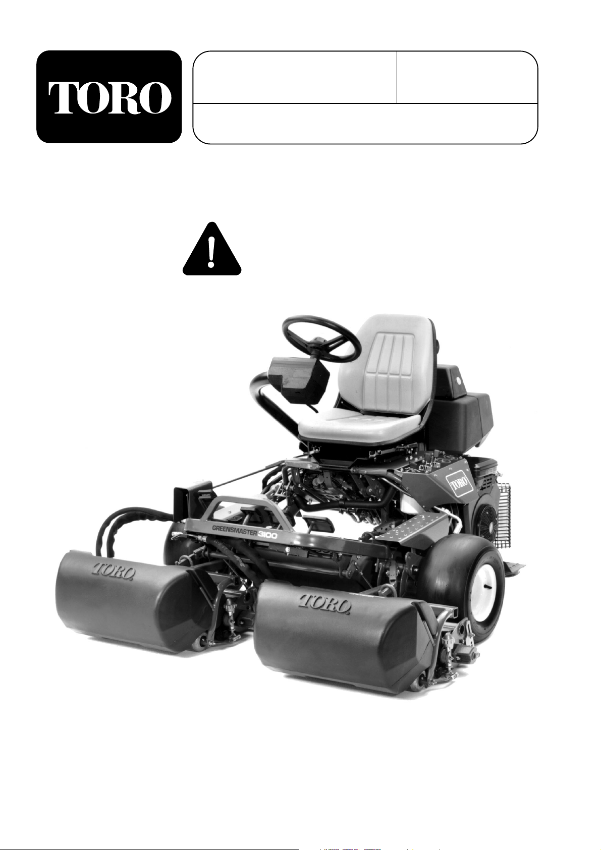
GREENSMASTER
OPERATOR’S
MANUAL
®
3100
Page 2

Forward
Table of Contents
2
Forward 2
Table of Contents 2
Safety 3
Sound & Vibration Levels 5
Symbol Glossary 6
Specifications 9
Set-Up 10
Install the Cutting Units 10
Installing Cutting Units 11
Rear Ballast 12
Before Operating 13
Check the Engine Oil 13
Fill the Gas Tank 13
Check the Hydraulic System 14
Tire Pressure 15
Check Wheel Nut Torque 15
Controls 16
Operating Instructions 18
Break-In Period 18
Starting Instructions 18
Check the Interlock System Operation 18
Check the Leak Detector Operation 20
Preparing the Machine for Mowing 21
Training Period 21
Before Mowing 21
Mowing Procedures 21
Leak Detector Operation 22
Transport Operation 23
Inspection and Clean-Up After Mowing 23
Maintenance 24
Maintenance Schedule 24
Lubrication 26
Changing the Engine Oil and Filter 28
Servicing the Air Cleaner 28
Adjusting the Throttle Control 29
Adjusting the Choke Control 29
Adjusting Carburetor and Speed Control 29
Replacing Spark Plugs 30
Fuel Filter Replacement 30
Changing the Hydraulic Oil and Filter 31
Checking Hydraulic Hoses and Lines 31
Brake Adjustment 32
Rear Camshaft Adjustment 32
Adjusting the Lift and Mow Pedal Height 33
Leveling the Lift and Mow Pedals 33
Adjusting the Traction Pedal 33
Adjusting the Cutting Unit Lift/Drop 34
Adjusting the Lift Cylinders 35
Seat Switch Maintenance 35
Traction Switch Maintenance 35
Mow/Lift Switch Maintenance 36
Adjusting the Traction Return Linkage 36
Battery Care 36
Troubleshooting 38
Storage 44
Identification and Ordering 44
The Greensmaster 3100 was developed to provide an efficient, trouble-free and time-saving method of mowing
high-quality turf on the finest greens. The latest concepts in engineering, design and safety have been
incorporated into this machine, along with the highest quality parts and workmanship. This product will provide
excellent service if you follow proper operation and maintenance practices.
We know, because you have purchased the industry leader in mowing excellence, that future performance and
dependability are of prime importance. Therefore, this manual should be read by you and all others involved
with the Greensmaster 3100 to make sure that safety, operation and maintenance procedures are followed.
Page 3

Safety
Training
1. Read the instructions carefully. Be familiar with
the controls and the proper use of the equipment.
2. Never allow children or people unfamiliar with
these instructions to use the lawn mower. Local
regulations may restrict the age of the operator.
3. Never mow while people, especially children, or
pets are nearby.
4. Keep in mind that the operator or user is
responsible for accidents or hazards occurring to
other people or their property.
5. Do not carry passengers.
6. All drivers should seek and obtain professional
and practical instruction. Such instruction should
emphasize:
• the need for care and concentration when
working with ride-on machines;
• control of a ride-on machine sliding on a
slope will not be regained by the application
of the brake. The main reasons for loss of
control are:
– insufficient wheel grip;
– being driven too fast;
– inadequate braking;
– the type of machine is unsuitable for its
task;
– lack of awareness of the effects of
ground conditions, especially slopes;
– incorrect hitching and load distribution.
Preparation
1. While mowing, always wear substantial footwear
and long trousers. Do not operate the equipment
when barefoot or wearing open sandals.
2. Thoroughly inspect the area where the equipment
is to be used and remove all objects which may
be thrown by the machine.
3. WARNING—Petrol is highly flammable.
• Store fuel in containers specifically
designed for this purpose.
• Refuel outdoors only and do not smoke
while refueling.
• Add fuel before starting the engine. Never
remove the cap of the fuel tank or add petrol
while the engine is running or when the
engine is hot.
• If petrol is spilled, do not attempt to start the
engine but move the machine away from the
are of spillage and avoid creating any source
of ignition until petrol vapors have
dissipated.
• Replace all fuel tanks and container caps
securely.
4. Replace faulty silencers.
Operation
1. Do not operate the engine in a confined space
where dangerous carbon monoxide fumes can
collect.
2. Mow only in daylight or in good artificial light.
3. Before attempting to start the engine, disengage
all blade attachment clutches and shift into
neutral.
4. Do not use on slopes of more than:
• Never mow side hills over 5°
• Never mow uphill over 10°
• Never mow downhill over 15°
5. Remember there is no such thing as a “safe”
slope. Travel on grass slopes requires particular
care. To guard against overturning:
• do not stop or start suddenly when going up
or downhill;
• engage the clutch slowly, and always keep
the machine in gear, especially when
travailing downhill;
• machine speeds should be kept low on
slopes and during tight turns;
3
Page 4

4
• stay alert for bumps and hollows and other
hidden hazards;
• never mow across the face of the slope,
unless the lawn mower is designed for this
purpose.
6. Use care when pulling loads or using heavy
equipment.
• Use only approved drawbar hitch points.
• Limit loads to those you can safely control.
• Do not turn sharply. Use care when
reversing.
• Use counterweight(s) or wheel weights
when suggested in the instruction handbook.
7. Watch out for traffic when crossing or near
roadways.
8. Stop the blades rotating before crossing surfaces
other than grass.
9. When using any attachments, never direct
discharge of material toward bystanders nor
allow anyone near the machine while in
operation .
10. Never operate the lawn mower with defective
guards, shields or without safety protective
devices in place.
11. Do not change the engine governor settings or
overspeed the engine. Operating the engine at
excessive speeds may increase the hazard of
personal injury.
12. Before leaving the operator’s position:
• Disengage the power take-off and lower the
attachments;
• Change into neutral and set the parking
brake;
• Stop the engine and remove the key.
13. Disengage the drive to attachments when
transporting or not in use.
14. Stop the engine and disengage the drive to the
attachment
• Before refueling;
• Before removing the grass catcher;
• Before making height adjustments unless
the adjustment can be made from the
operator’s position.
• Before clearing blockages;
• Before checking, cleaning or working on the
lawnmower;
• After striking a foreign object. Inspect the
lawnmower for damage and make repairs
before restarting and operating the
equipment.
15. Reduce the throttle setting during engine runout
and, if the engine is provided with a shutoff
valve, turn the fuel off at the conclusion of
mowing.
Maintenance and Storage
1. Keep all nuts, bolts and screws tight to be sure
the equipment is in safe working condition.
2. Never store the equipment with petrol in the tank
inside a building where fumes may reach an open
flame or spark.
3. Allow the engine to cool before storing in any
enclosure.
4. To reduce the fire hazard, keep the engine,
silencer, battery compartment and petrol storage
area free of grass, leaves, or excessive grease.
5. Check the grass catcher frequently for wear or
deterioration.
6. Replace worn or damaged parts for safety.
7. If the fuel tank has to be drained, this should be
done outdoors.
8. Be careful during adjustment of the machine to
prevent entrapment of the fingers between
moving blades and fixed parts of the machine.
9. On multi-bladed machines, take care as rotating
one blade can cause other blades to rotate.
10. When the machine is to be parked, stored or left
unattended, lower the cutting means unless a
positive mechanical lock is used.
Page 5

Sound & Vibration Levels
Sound Levels
This unit has an equivalent continuous A-weighted
sound pressure at the operator ear of: 86 dB(A), based
on measurements of identical machines per
84/538/EEC.
This unit has a sound power level of 100 dB(A)/1pW,
based on measurements of identical machines per
procedures outlined in Directive 79/113/EEC and
amendments.
Vibration Levels
This unit has a vibration level of 2.5 m/s2at the
posterior, based on measurements of identical
machines per ISO 2631 procedures.
This unit does not exceed a vibration level of 0.5 m/s
2
at the posterior based on measurements of identical
machines per ISO 2631 procedures.
5
Page 6
6
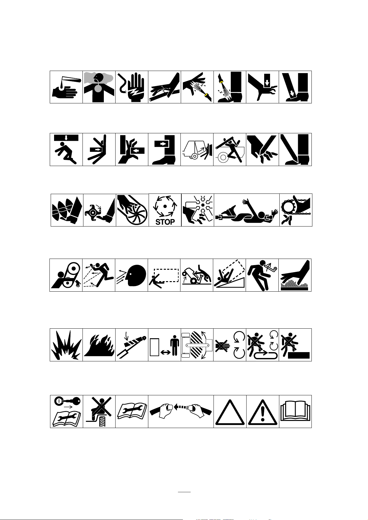
Symbol Glossary
Caustic liquids,
chemical burns to
fingers or hand
Crushing of
whole body,
applied from
above
Cutting or
entanglement of
foot, rotating auger
Poisonous
fumes or toxic
gases, asphyxiation
Crushing of
torso, force
applied from side
Severing of
foot, rotating
knives
Electrical shock,
electrocution
Crushing of fingers
or hand/, force
applied from side
Severing of
fingers or hand,
impeller blade
High pressure
fluid, injection
into body
force applied
from side
Wait until all
machine
components have
completely stopped
before touching them
High pressure
spray, erosion of
flesh
Crushing of
whole body
Severing of
fingers or hand,
engine fan
High pressure
spray, erosion of
flesh
Crushing of
head, torso and
arms
Whole body entanglement,
implement input drive line
Crushing of
fingers
or hand,
force
applied from
above
Cutting of
fingers or hand
Crushing of
toes or foot, force
applied from above
Cutting of footCrushing of leg,
Fingers or
hand entanglement, chain drive
Hand & arm
entanglement,
belt drive
Explosion Fire or open
Shut off engine
& remove key before
performing maintenance or repair work
Thrown or flying objects, whole
body exposure
flame
Riding on this
machine is allowed
only on a passenger seat & only if the
driver’s view is not
hindered
Thrown or
flying objects,
face exposure
Secure lifting
cylinder with locking
device before getting
in hazardous area
Consult
technical manual
for proper service
procedures
Runover/backover, (relevant
machine to appear
in dashed box)
Stay a safe
distance from
the machine
Fasten seat belts Safety alert
Machine tipping,
riding mower
Stay clear of
articulation area
while engine is
running
Machine rollover,
ROPS (relevant
machine to appear
in dashed box)
Stored energy
hazard, kickback
or upward motion
Do not open
or remove safety
shields while
engine is
running
triangle
Do not step on
loading platform if
PTO is connected to tractor
& engine is running
outline safety
alert symbol
Hot surfaces,
burns to fingers
or hands
Do not step
Read operator’s
manual
Page 7

7
Symbol Glossary
Page 8
8
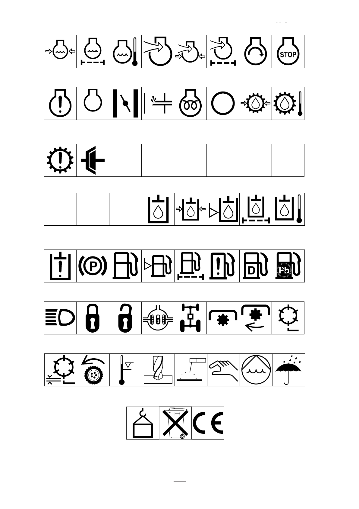
Reel 3
Engine coolant
pressure
Engine coolant f
ilter
n/min
Engine failure/
malfunction
Transmission
failure/malfunction
Engine rotational
speed/frequency
Clutch Neutral High Low Forward Reverse Park
231
First gear Second gear
Engine
lubricating oil
pressure
Choke Primer (start aid) Electrical preheat
Engine intake/
combustion air
Engine intake/
combustion air
pressure
(low temperature
start aid)
Engine intake/
air filter
Transmission oil Transmission oil
Engine start Engine stop
pressure
Transmission oil
temperature
NHLFRP
Third gear (other #'s
may be used until
the maximum # of forward gears is reached.)
Hydraulic oil Hydraulic oil
Hydraulic oil
pressure
Hydraulic oil level Hydraulic oil filter
temperature
Hydraulic oil
failure/malfunction
Headlights Lock Unlock Differential lock 4-Wheel drive Pow er Take-Off Power Take-Off,
Reel cutting
element, height
adjustment
Parking brake Fuel
Traction Above working
temperature range
0430 weight Do not dispose
Fuel level Fuel filter Fuel system
Drilling Manual metal arc
welding
in the garbage
failure/malfunction
Manual 0356 Water pump
CE logo
Diesel fuel Unleaded fuel
rotational speed
Reel cutting
element
0626 Keep dry
Page 9

9
Configuration: Tricycle vehicle with the front two
wheels providing drive and the rear wheel providing
steering. The operator sits in the center over the No. 1
cutting unit with the No. 2 & 3 cutting units in front
of the vehicle.
Power: 4-cycle gasoline engine, electric start, with
output of 13.4 kW @3,600 rpm. Maximum no-load
governed engine speed is 2,900 rpm.
Traction: All-hydraulic drive, consisting of multiple
stack pump valve, valve, and two orbital gear motors
to drive the front wheels.
Cutting Units: All-hydraulic drive, consisting of
three gear pump sections, three valve sections and
three gear motors that drive the reels.
Hydraulic Valve: Five spool sections: the first 3
spool sections control the lowering, mowing and lift
functions of the cutting units. The spools moved out
provide lowering and MOW operation; moved in they
provide LIFT operation. The number 4 spool section
controls the traction functions, N (Neutral), 1 (Mow),
and 2 (transport). The number 5 spool section
controls forward and reverse traction.
Tire Pressure :
• 55–83 kPa—front
• 55–103 kPa—rear
Brakes: 15 cm drum-type mechanical with rack and
pawl lock for parking.
Hydraulic Filter: 10-micron, cartridge type.
Hydraulic Oil Reservoir: 32.2 liter capacity with
internal baffle. Type fluid: Mobil 15M. Red dye is
added at the factory.
Gas Tank: 28.4 liter capacity.
Fuel Filter: In-line type.
Fuel Pump: Vacuum pulse type.
Seat Adjustment: 17.8 cm (forward and rearward).
Wheel Bearings:
Drive Wheels: Needle provided in wheel motors.
Rear Caster Wheels: Timken tapered roller
Electrical & Instrumentation: The engine contains a
18-amp alternator; the circuit is fused at 20 amps.
Instruments include ammeter and hour meter. An
accessory terminal is available at the leak detector test
switch if attachment of headlights is desired.
Battery: 12-Volt, lead acid, 32-amp. hour. Size:
Length—18.4cm, Width—12.4cm, height—15.2cm.
General Specifications:
Width of Cut: 149.9 cm
Wheel Tread: 123.3 cm
Wheel Base: 119 cm
Overall Length: 229 cm
Overall Width: 177 cm
Overall Height: 123 cm
Net Weight (Wet): 381 kg
Shipping Weight (In carton): 471 kg
Speeds:
1st —6.1 kmh
2nd—13 kmh
Rev.—3.1 kmh
Reels: 1,975 rpm (approximately)
Clip:
0.46 cm (11-Blade Cutting Unit)
0.64 cm (8-Blade Cutting Unit)
1.0 cm (5-Blade Cutting Unit)
Specifications and design subject to change
without notice
.
Specifications
Page 10
10
Install the Cutting Units
For Cutting Unit Models 04404, 04406, 04408
04450 and 04468.
Note: When sharpening, setting height of cut, or
performing other maintenance procedures on the
cutting units, store the cutting unit reel motors in
support tubes on the front of the frame to prevent
damage to the hoses.
1. Remove the cutting units from their cartons.
Assemble and adjust according to the operator’s
manual for the cutting units. Use the height
gauge bar from the loose parts kit to adjust height
of cut.
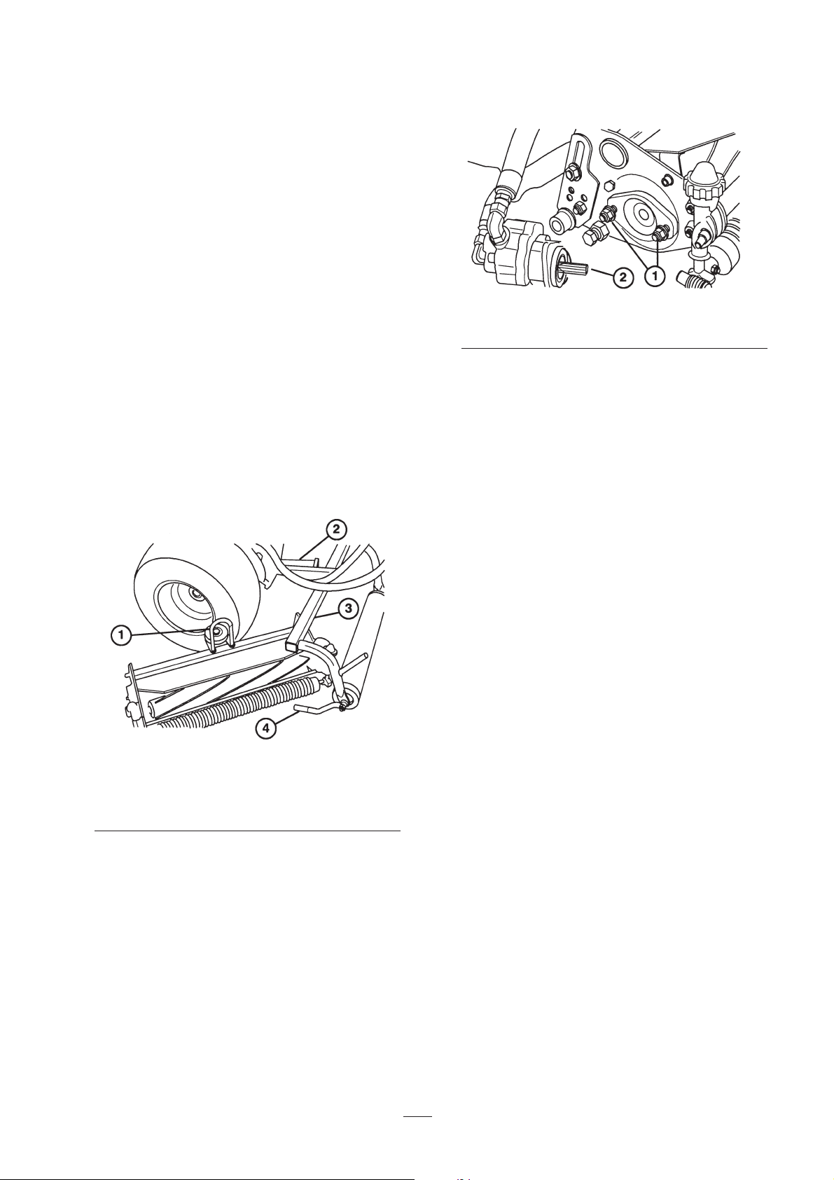
2. Slide the cutting units under the pull frames and
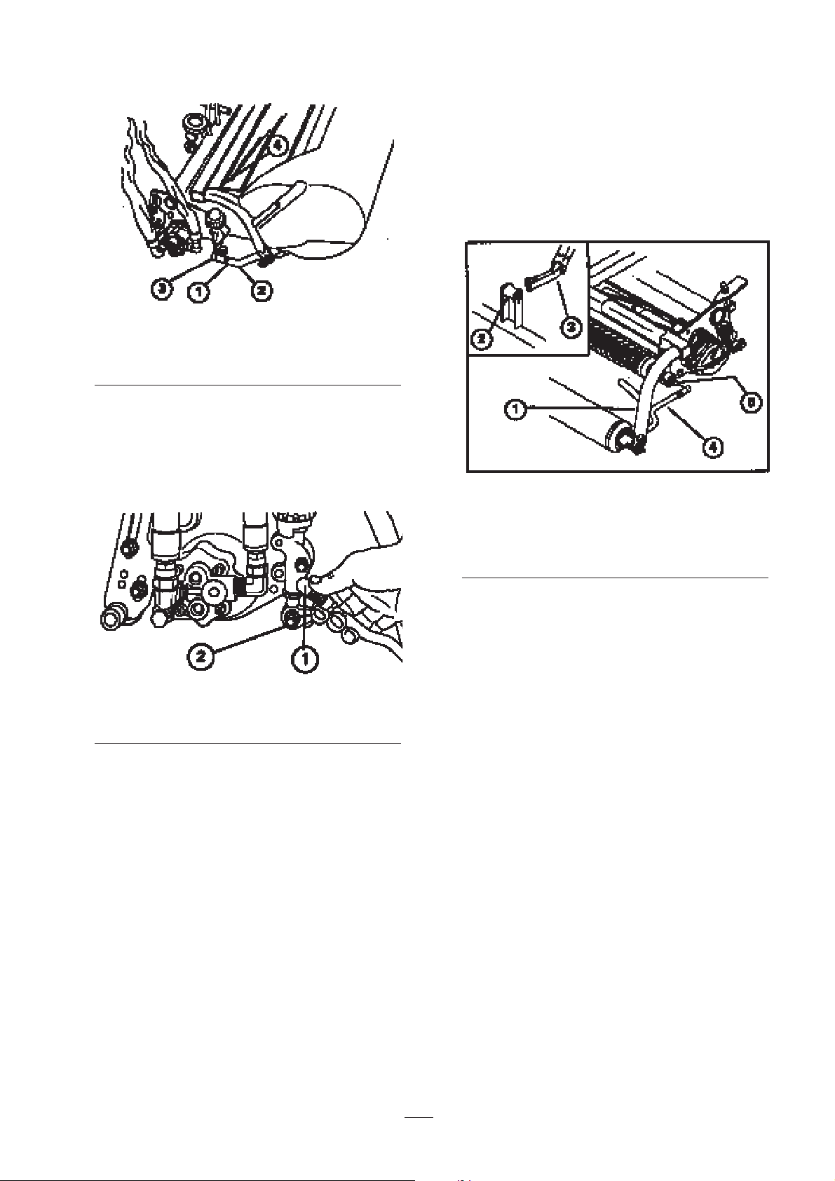
position the hoop on the top of cutting units over
the lift arms (Fig. 1).
Figure 1
1. Hoop
2. Lift arm
3. Pull frame
4. Pull arm
3. Assemble the mount nuts for the reel drive motor
to each cutting unit. Leave approximately 1.2cm
of threads exposed on each mount stud (Fig. 2).
Figure 2
1. Motor mount nuts
2. Coat with grease
4. Remove the protective covers from the cutting
units and the reel drive motor shafts. Coat the
spline shaft of the motor with clean grease and
install the motor by turning the motor clockwise
so the motor flanges clear the studs. Rotate the
motor counterclockwise until the flanges encircle
the studs, then tighten the mounting nuts (Fig. 2).
Note: Retain the protective covers for the cutting
units. Install them whenever the reel drive
motors are removed to protect the cutting unit
bearings from contamination.
5. Slide the sleeve back on the ball joint and rotate
the pull arm down so the socket fits over the ball
stud. Release the sleeve so it slides over the stud
and locks the assemblies together (Fig. 4).
6. Mount the baskets on the pull frames, loosen the
jam nuts on the pull arms and adjust the ball
sockets until there is 6–11mm clearance between
the lip of the basket and the reel blades (Fig. 3).
Note: This prevents the basket from tipping the
cutting unit forward, causing the hoop to come
off the lift arm while mowing.
Be sure the basket lips are equidistant from the
reel blades all across each reel. If the basket is
too close to the reel, it is possible for the reel to
contact the basket when the cutting unit is raised
off the ground.
Set-Up
Page 11
11
Figure 3
1. Jam nut
2. Pull arm
3. Ball joint-adjust for clearance
4. 6–11mm clearance
7. Align the sockets in the ball joints so the open
side of the socket is centered toward the ball
stud. Tighten the jam nuts to secure the sockets
in position (Fig. 3).
Figure 4
1. Slide back to mount
2. Ball stud
Installing Cutting Units
For Cutting Unit Models 04480, 04481, 04482, and
04483.
Note: When sharpening, setting height of cut or
performing other maintenance procedures on the
cutting units, store the cutting unit reel motors in
support tubes on the front of the frame to prevent
damage to the hoses.
1. Remove the cutting units from their cartons.
Assemble and adjust according to the operator’s
manual for the cutting units. Use the height
gauge bar from the loose parts kit to adjust height
of cut.
2. Mount a washer and ball stud to each end of the
front roller on the cutting units (Fig. 5).
3. Slide the cutting unit under the pull frame while
hooking the lift roller onto the lift arm (Fig. 5).
Figure 5
1. Pull frame
2. Lift roller
3. Lift arm
4. Pull arm
5. Ball stud
4. Slide the sleeve back on the ball joint and rotate
the pull arm down so the socket fits over the ball
stud. Release the sleeve so that it slides over the
stud and locks the assemblies together (Fig. 6).
5. Mount the baskets on the pull frames, loosen the
jam nuts on the pull arms and adjust the ball
sockets until there is 6–11mm clearance between
the lip of the basket and the reel blades or front
shield.
Note: This prevents the basket from tipping the
cutting unit forward causing the lift roller to
come off the lift arm while mowing.
Be sure the basket lips are equidistant from the
reel blades all across each reel. If the basket is
too close to the reel, it’s possible for the reel to
contact the basket when the cutting unit is raised
off the ground.
Page 12
12
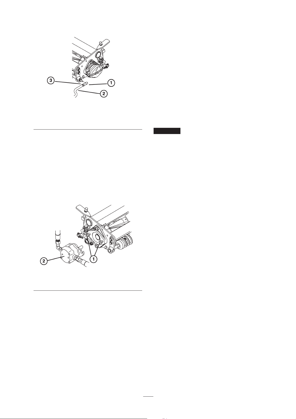
Figure 6
1. Ball joint
2. Pull arm
3. Jam nut
6. Align the sockets in the ball joints so the open
side of the socket is centered toward the ball
stud. Tighten the jam nuts to secure the sockets
in position (Fig. 6).
7. Assemble the mounting capscrews for the reel
drive motor to each cutting unit. Leave
approximately 1.2cm of thread exposed on each
mounting capscrew (Fig. 7).
Figure 7
1. Capscrews
2. Drive motor
8. Remove the protective covers from the cutting
units and the reel drive motor shafts.
Note: Retain the protective covers for the cutting
units. Install them whenever the reel drive
motors are removed to protect the cutting unit
bearings from contamination.
9. Using a hand pump grease gun, fill the cavity at
the end of the cutting unit with #2 general
purpose grease.
10. Coat the spline shaft of the motor with clean
grease and install the motor by rotating the motor
clockwise so that the motor flanges clear the
studs. Rotate the motor counterclockwise until
the flanges encircle the studs, then tighten the
mounting capscrews (Fig. 7).
Rear Ballast
This unit complies with the ANSI B71.4-1999
Standard when 40 lbs. of calcium chloride ballast is
added to the rear wheel.
If a puncture occurs in a tire with
calcium chloride, remove the unit from the turf area as
quickly as possible. To prevent possible damage to
turf, immediately soak the affected area with water.
Important
Page 13
13
Check the Engine Oil
The engine is shipped with 1.7 liter (with filter) of oil
in the crankcase; however, the level of oil must be
checked before and after you first start the engine.
1. Position the machine on a level surface.
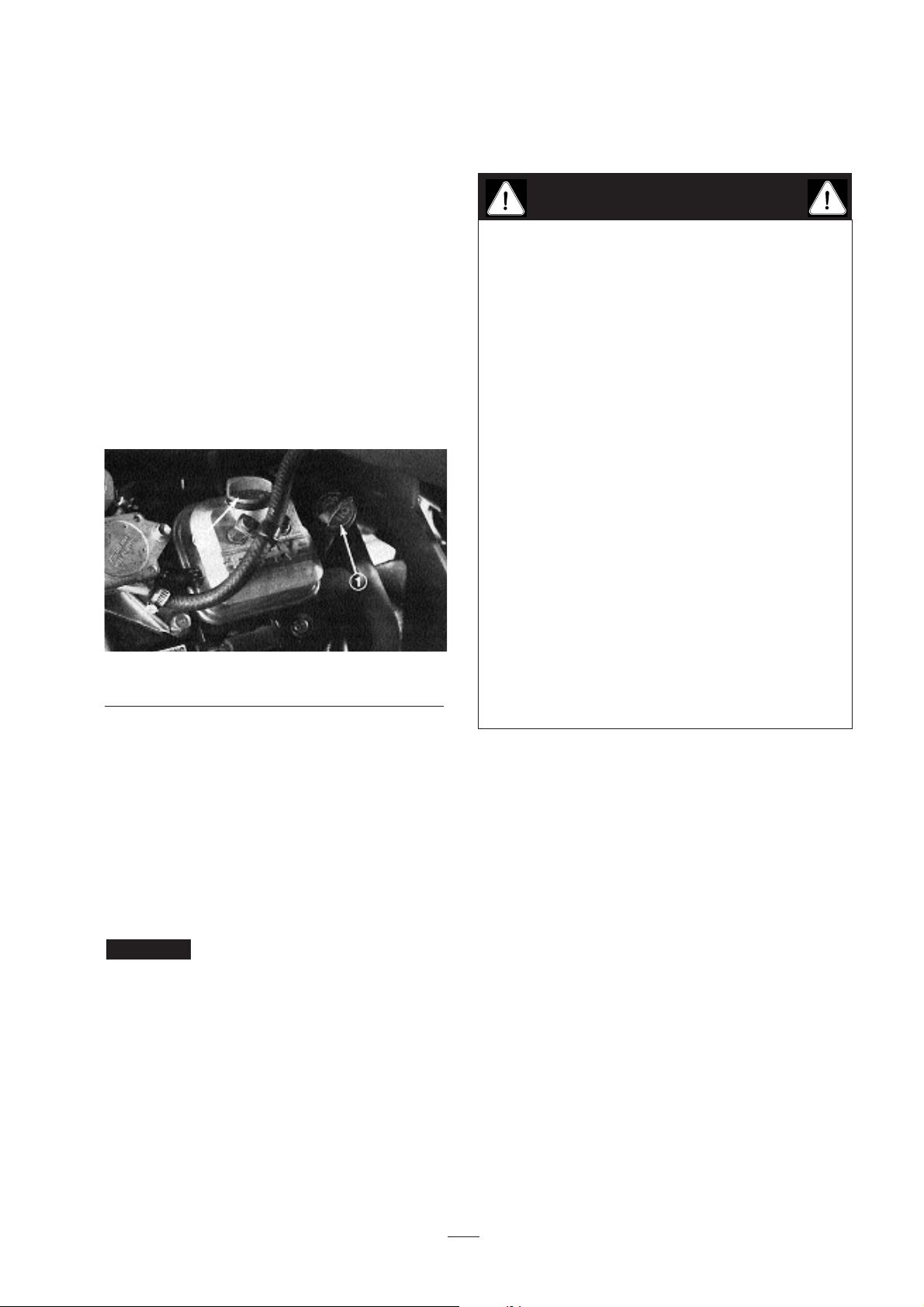
2. Unscrew the dipstick and wipe it with a clean
cloth. Screw the dipstick into the tube and make
sure it is seated fully. Unscrew the dipstick and
check the oil level. If it is low, remove the filler
cap from the valve cover and add enough oil to
raise the level to the FULL mark on the dipstick.
Figure 8
1. Dipstick
2. Fill Cap
3. The engine uses any high-quality detergent oil
having the American Petroleum Institute —
API—service classification SC, SD, SE, SF or
SG. Recommended viscosity (weight) is SAE
30.
4. Pour the oil into the opening in the valve cover
until the oil level is up to the FULL mark on the
dipstick. Add the oil slowly and check the level
often during this process. DO NOT OVERFILL.
Check the oil level every 8
operating hours or daily. Initially change the oil
and filter after the first 8 hours of operation; after
that—under normal conditions—change the oil
after every 50 hours and the filter after every 100
hours. However, change the oil more often when
you operate the engine in extremely dusty or
dirty conditions.
5. Install the dipstick firmly in place.
Fill the Gas Tank
THE TORO COMPANY STRONGLY
RECOMMENDS THE USE OF CLEAN, FRESH
UNLEADED REGULAR GASOLINE IN TORO
GASOLINE-POWERED PRODUCTS. UNLEADED
GASOLINE BURNS CLEANER, EXTENDS
ENGINE LIFE, AND PROMOTES GOOD
STARTING BY REDUCING THE BUILD-UP OF
COMBUSTION CHAMBER DEPOSITS. LEADED
GASOLINE CAN BE USED IF UNLEADED IS
NOT AVAILABLE.
NOTE: Never use methanol, gasoline containing
methanol, gasohol containing more than 10% ethanol,
gasoline additives, premium gasoline, or white gas
because the engine fuel system damage could result.
1. Fill the gasoline tank to the bottom of the filler
neck. DO NOT OVERFILL. Install the cap and
tighten it securely in place.
Important
Before Operating
Because gasoline is flammable, use caution when
storing or handling lt. Do not fill the fuel tank
while the engine is running, or hot, or when the
machine is in an enclosed area. Vapors may
build up and be ignited by a spark or flame
source many feet away. DO NOT SMOKE while
filling the fuel tank to prevent the possibility of
an explosion. Always fill the fuel tank outside
and wipe up any spilled gasoline before starting
the engine. Use a funnel or spout to prevent
spilling gasoline before starting the engine and
fill the tank to about 1 inch from the top of the
tank, not the filler neck. Store gasoline in a clean
safety-approved container and keep the cap in
place on the container. Keep gasoline in a cool,
well-ventilated place—never in an enclosed area
such as a hot storage shed. To assure volatility,
do not buy more than a 30-day supply of
gasoline. Gasoline is a fuel for internal
combustion engines; therefore, do not use it for
any other purpose. Since many children like the
smell of gas, keep it out of their reach because the
fumes are explosive and dangerous to inhale.
DANGER
Page 14

14
Figure 9
1. Fuel tank cap
Check the Hydraulic System
The hydraulic system is designed to operate on antiwear hydraulic fluid. The machine’s reservoir is filled
at the factory with 8.5 gallons (32.2 l) of Mobil 15M
hydraulic fluid. Check the level of hydraulic fluid
before the engine is first started and daily
thereafter.
Group 1 Hydraulic Fluid (Moderate climate—
average duty)
Note: The fluids within this group are
interchangeable.
ISO VG 46/48 multi-viscosity anti-wear hydraulic
fluid
Mobil DTE 15M
Amoco Rycon Premium ISO 46
Castrol AWH 46
Conoco Hydroclear AW MV68
Gulf Harmony HVI 46 AW
Kendall Hyken Golden MV SAE 5W-20
Pennzbell AWX MV46
Phillips Magnus A KV 5W-20
Shell Tellus T 46
Sunoco Sun Hyd. Oil 2105
Texaco Rando HDZ 46
Universal Tractor Hydraulic Fluid
Mobil Mobilfluid 424
Amoco 1000 Fluid
Chevron Tractor Hydraulic Fluid
Conoco Hydroclear Powertran
Esso Hydraul
Gulf Universal Tractor Fluid
Kendall Hyken 052
Marathon Marafluid Super HT
Pennzoil Hydra-trans
Phillips HG Fluid
Shell Donax TD
76 Lubricants Hydraulic/Tractor Fluid
Sunoco TH Fluid
Texaco TDH
Group 2 Hydraulic Fluid (Hot Climate—Heavy
Duty)
Note: The fluids within this group are
interchangeable.
ISO VG 68 anti-wear hydraulic fluid
Mobil DTE 26
Amoco Rykon AW No. 68
Castrol AWS 68
Chevron Hydraulic Oil AW ISO 68
Conoco Hydroclear AW 68
Exxon Nuto H 68
Gulf Harmony 68AW
Kendall Four Seasons AW68
Marathon ISO 68
Pennzoil IAW Hydraulic Oil 68
Phillips Magnus A ISO 68
Shell Tellus 68
76 Lubricants AW 68
Sunoco SunVis 868
Texaco Rando HD 68
Group 1 fluids are recommended for use
at typical ambient temperatures of 0°C to 41°C. The
ISO type 46/68 fluid has been found to offer optimal
performance in a wide range of temperature
conditions for the average user. The Universal Tractor
Fluids offer similar performance for those who prefer
them, with perhaps some slight loss of efficiency at
high ambient temperatures compared with the Type
46/48 fluids
Group 2 fluids are recommended for heavy-duty
use in hot climates where ambient temperatures
range from about 20°C to 49°C. Use at lower
ambient temperatures may result in hard starting,
increased engine laboring while cold, sluggish or
non-operating spool valves while cold and high
Important
1
Page 15
15
filter back-pressure due to the higher viscosity of
these fluids.
Note: When changing from one type of hydraulic
fluid to another, be certain to remove all the old fluid
from the system because some brands are not
completely compatible with other brands of hydraulic
fluid.
Group 3 Hydraulic Fluid (biodegradable):
ISO VG 32/46 anti-wear hydraulic fluid
Mobil EAL 224H
Note: This biodegradable hydraulic fluid is not
compatible with the fluids in groups 1 or 2
Note: When changing from standard fluid to the
biodegradable type, be certain to follow approved
flushing procedures as published by Mobil. Contact
your local Toro distributor for details.
Use only types of hydraulic fluids
specified. Other fluids could cause system damage.
Note: A red dye additive for the hydraulic system
fluid is available in19.8 ml bottles. One bottle is
sufficient for 22 L of hydraulic fluid. Order Part No.
44-2500 from your Authorized Toro Distributor.
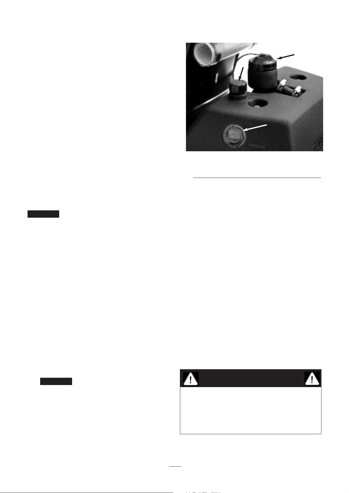
1. Position the machine on a level surface. Make
sure the machine has cooled down so fluid is
cold. Check the level of oil by viewing the sight
gauge on the side of the auxiliary oil tank. If the
oil level is up to the FULL mark next to the
gauge, the oil level is sufficient.
2. If the oil level is below the FULL mark on the
auxiliary tank, remove the cap from the hydraulic
oil tank and slowly fill the tank with Mobil 15M
or equivalent hydraulic oil until the level is up to
the mark next to the sight gauge. Do not mix
oils. Install the cap.
To prevent system contamination,
clean the tops of hydraulic fluid containers
before puncturing them. Assure the pour spout
and funnel are clean.
Figure 10
1. Sight gauge
2. Hydraulic tank cap
3. Auxiliary tank breather
NOTE: Make a close visual inspection of the
hydraulic components. Inspect for leaks, loose
fasteners, missing parts, improperly routed lines, etc.
Make any corrections necessary.
Tire Pressure
The tires are over-inflated at the factory for shipping.
Reduce the tire pressure to the proper levels before
starting the unit.
Vary the tire pressure for the drive wheels, depending
on your turf conditions, from a minimum of 55 KPa to
a maximum of 83 KPa
Vary the tire pressure for the rear wheel from a
minimum of 55 KPa to a maximum of 103 KPa.
Traction improves with lower tire pressure.
Check Wheel Nut Torque
Important
Important
1
2
3
Torque the wheel nuts to 95–122 N•m after one to
four hours of operation and again after 10 hours of
operation, then every 200 hours thereafter. Failure
to maintain proper torque could result in personal
injury.
WARNING
Page 16
16
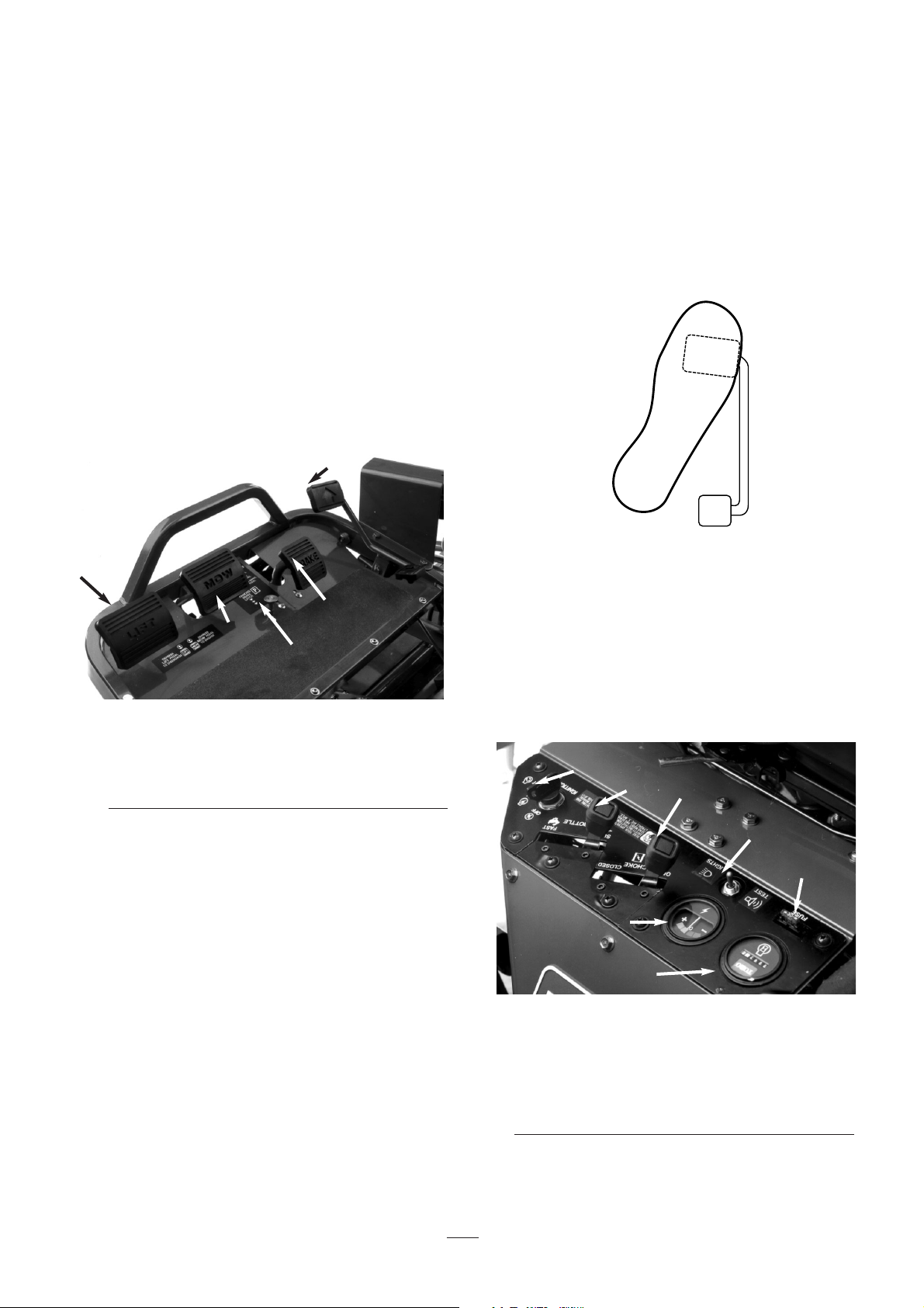
MOW PEDAL (Fig. 11)—Depressing the mow pedal
FULLY during operation lowers the cutting units and
starts the reels. The mow pedal will stay depressed so
the operator need not hold the pedal down.
BRAKE PEDAL (Fig. 11)—The brake pedal actuates
an automotive drum-type mechanical brake at each
traction wheel.
LIFT PEDAL (Fig. 11)—Depressing the lift pedal
during operation stops the reels from turning and lifts
the cutting units. The lift pedal must be FULLY
depressed until the cutting units are fully raised and
have stopped rotating.
Figure 11
1. Mow pedal
2. Lift pedal
3. Traction pedal
4. Brake pedal
5. Parking brake button
PARKING BRAKE BUTTON (Fig. 11)—
Depressing the brake pedal to actuate the brake
assembly, then depressing the parking brake button
will keep the brakes engaged for parking. Disengage
by depressing the brake pedal. Form the habit of
locking the parking brake before you leave the
machine.
TRACTION PEDAL (Fig. 11)—The traction pedal
makes the machine move forward, backward or stop.
Depress the top of the pedal to move forward and the
bottom of the pedal to move backward. Also, allow
the pedal to move to the neutral position to stop the
machine. Do not rest your heel on reverse when
operating forward (Fig. 12).
THROTTLE CONTROL (Fig. 13)—The throttle
controls the engine speed. Moving the throttle control
toward FAST increases engine rpm; moving the
throttle toward SLOW decreases engine rpm.
NOTE: You cannot stop the engine using the throttle
control.
Figure 12
CHOKE (Fig. 13) —To start a cold engine, close the
carburetor choke by moving the choke control
forward to the CLOSED position. After the engine
starts, regulate the choke to keep the engine running
smoothly. As soon as possible, open the choke by
pulling it rearward to OPEN. A warm engine requires
little or no choking.
Figure 13
1. Choke control
2. Throttle control
3. Ignition switch
4. Ammeter
5. Leak detector test / light switch
6. Hour meter
7. Fuse (20 amp)
IGNITION SWITCH (Fig. 13)—Insert the key into
Controls
2
2
1
5
4
3
3
1
5
4
6
7
Forward
Rev
Page 17
17
the switch and turn it clockwise to the START
position to start the engine. Release the key as soon
as the engine starts. Turn the key counter-clockwise
to OFF to stop the engine
VOLT METER (Fig. 13)—The ammeter shows the
electrical system voltage.
FUSE (Fig. 13)—The 10-amp fuse is part of the
electrical circuit.
LEAK DETECTOR TEST/LIGHT SWITCH (Fig.
13) From the middle operating position, move the
switch rearward to check the operation of the leak
detector alarm and time delay. Move the switch
forward to operate optional headlights.
HOUR METER (Fig. 13)—Shows the total hours of
machine operation. The hour meter starts whenever
the key switch is turned to ON.
SEAT ADJUSTING HANDLE (Fig. 13)—Located
on the left side of the seat, this lever allows four inch
fore-and-aft adjustment.
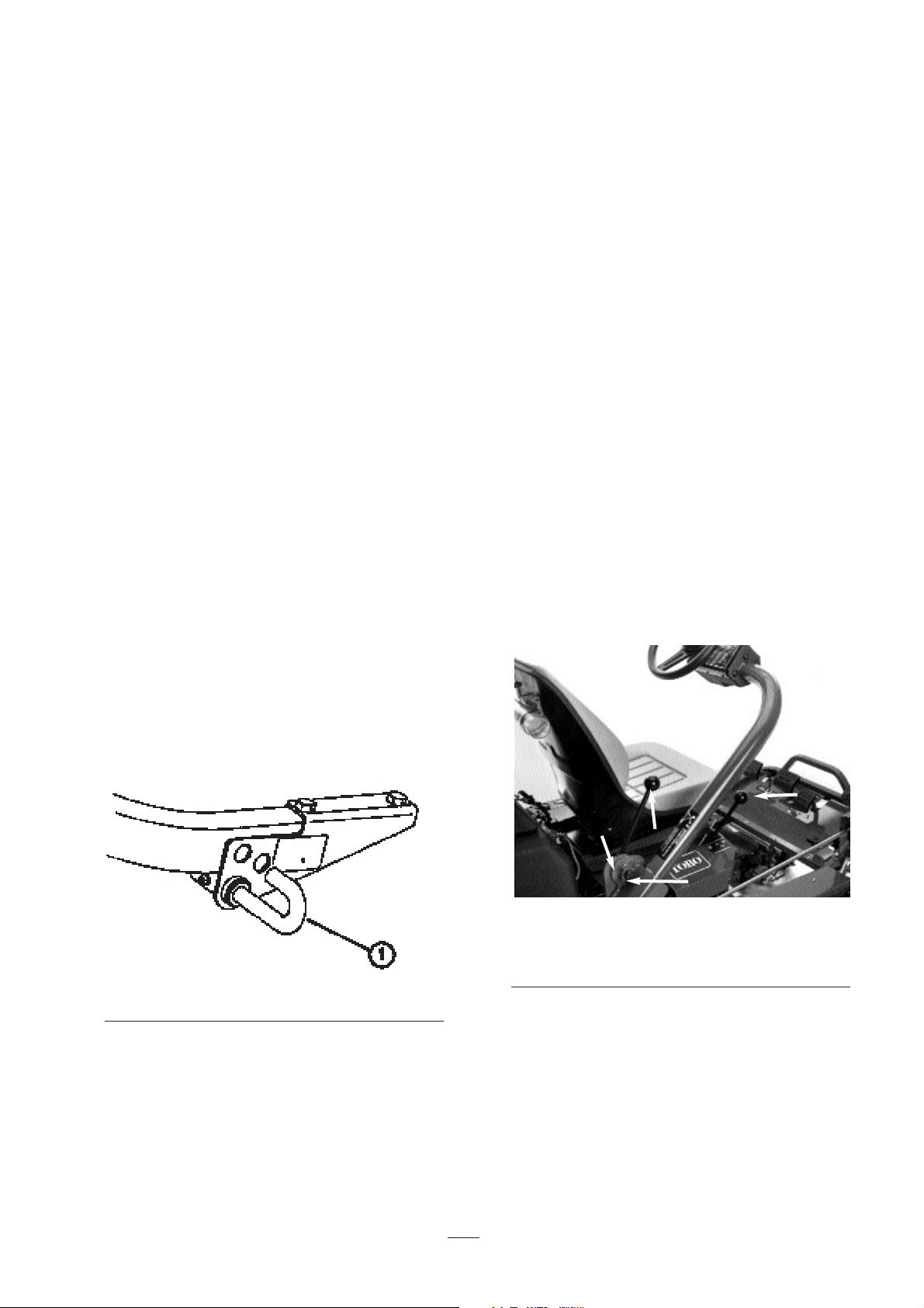
MOW LOCKOUT LEVER (Fig. 14)—locks the
mow pedal, preventing accidental starting of the
cutting units. To unlock, pull the mow lockout pin
outward, rotate it clockwise and insert the end into the
rear hole in the bracket.
Figure 14
1. Mow lockout lever pin
SHIFT SELECTOR (Fig. 15)—Provides two
traction selections, plus a NEUTRAL position. It is
permissible to shift from one selection to another
while the machine is in motion. No damage will
result.
1. Neutral—Used for starting the engine.
2. No. 1 Position—Used for greens mowing
operation.
3. No. 2 Position—Used for transport operation.
NOTE: If you operate the machine in reverse with the
cutting units down, they will be pulled off the lift
arms.
STEERING ARM LOCKING LEVER (Fig. 15)—
Rotate the lever rearward to loosen, then raise or
lower the steering arm for comfort. Then rotate the
lever forward to tighten.
To adjust the locking lever:
1. Rotate the lever rearward to loosen adjustment
and move the steering arm to its lowest position.
2. Loosen the lever set screw.
3. Rotate the adjusting bolt (left-hand thread)
counter-clockwise to tighten, or clockwise to
loosen the adjustment.
4. Tighten the set screw to lock the adjustment.
Figure 15
1. Shift selector
2. Steering arm locking lever
3. Set screw
4. Adjusting bolt
3
2
1
4
Page 18

18
6. Check the machine out with the following
procedures after the engine has started:
A. Move the throttle control to FAST and
momentarily engage the reels by depressing
the mow pedal (the cutting units should
drop and all reels should turn).
B. Operate the lift pedal; the cutting reels
should stop and the cutting units raise to full
transport position.
NOTE: Stop the engine. Check the lip of
each basket to be sure it doesn’t contact the
reel during operation. Re-adjust if the
basket does make contact.
C. Depress the brake pedal to keep the machine
from moving and operate the traction pedal
through the forward and reverse positions.
Continue the above procedure for 1–2
minutes.
D. Neutralize the traction lever and the mow
and lift pedals, lock the parking brake, and
turn the engine off. Check for oil leaks; if
oil leaks appear, check the tightness of the
hydraulic fittings. If oil leaks continue to
appear, contact your local TORO dealer for
assistance and, if necessary, replacement
parts.
The motor or wheel seals may show
some trace of oil for a short period of time until the
break-in period is completed.
NOTE: When the Greensmaster 3100 is new and the
bearings and reels are tight, it is necessary to use the
FAST throttle control position for this check. A fast
throttle setting may not be required after break-in.
Check the Interlock System
Operation
The interlock system prevents the engine from
cranking or starting unless the operator is on the seat,
the shift selector is in NEUTRAL and the cutting units
are DISENGAGED. Also, the engine will stop when
the cutting units are engaged or if the shift selector is
in the No. 1 or No. 2 position with operator off the
seat. Do the following system checks daily to make
Important
Break-In Period
1. Refer to the engine manual supplied with the
Greensmaster 3100 for oil change and maintenance
procedures recommended during break-in.
2. Only 8 hours of mowing operation is required for
the Greensmaster 3100 break-in period.
3. The first hours of operation are critical to future
dependability. Monitor performance closely so that
minor difficulties that could lead to major problems
can be corrected. Inspect the machine often during
break-in for signs of oil leakage, loose fasteners, or
any other malfunction.
4. To assure optimum performance of the brake
system, burnish (break-in) the brakes before use.
To burnish brakes: Firmly apply brakes and drive
the machine at mowing speed until the brakes are
hot, as indicated by their smell. An adjustment to
the brakes may be required after break-in. Refer to
Brake Adjustment.
Starting Instructions
Note: Inspect the areas beneath the mowers to make
sure they are clear of debris.
1. Unlock the mow lockout lever by pulling the pin
outward, rotating it clockwise and inserting the end
into the rear hole in the bracket.
2. Sit on the seat, place the shift selector in
NEUTRAL, and check the mow and lift pedals to
make sure they are level with one another.
3. Remove your foot from the traction pedal and
make sure the pedal is in neutral.
4. Move the choke lever to ON—when starting a cold
engine—and the throttle lever to the half-throttle
position.
5. Insert and turn the ignition key clockwise until the
engine starts. After the engine starts, regulate the
choke to keep the engine running smoothly. As
soon as possible, open the choke by pulling it
rearward to the OFF position. A warm engine
requires little or no choking.
Operating Instructions
Page 19
19
sure the interlock system operates correctly.
1. Sit on the seat, engage the parking brake, move
the shift selector to neutral, remove your foot
from the traction pedal and make sure the pedal
is in neutral, and depress the lift pedal and
release it. Try to start the engine. The engine
should crank and run, which means the interlock
system is operating correctly. If the engine did
not crank, go to step 2. If the engine cranked,
contact your local TORO dealer for assistance.
2. Sit on the seat, engage the parking brake and
depress the lift pedal fully and release it. Move
the shift selector to the #1 and #2 positions while
trying to start the engine in each position. The
engine should not crank, which means the
traction switch on the valve bank is operating
correctly. If the engine did not crank, go to step
3. If the engine cranked, contact your local
TORO dealer for assistance.
3. Sit on the seat, engage the parking brake, depress
the lift pedal and release it. Move the shift
selector to Neutral and try to start the engine.
The engine should start and continue to run,
which means the traction switch and the mow/lift
switch on valve bank are operating correctly—go
to step 4. If the engine cranked but did not start,
the problem is not in the interlock system. If the
engine did not crank, contact your local TORO
dealer for assistance.
4. Sit on the seat, engage the parking brake and
move the shift selector to neutral. Depress the
mow pedal and try to start the engine. The
engine should not crank, which means the mowlift switch is operating correctly. If the engine
did not crank, go to step 5. If the engine
cranked, ask your local TORO dealer for
assistance.
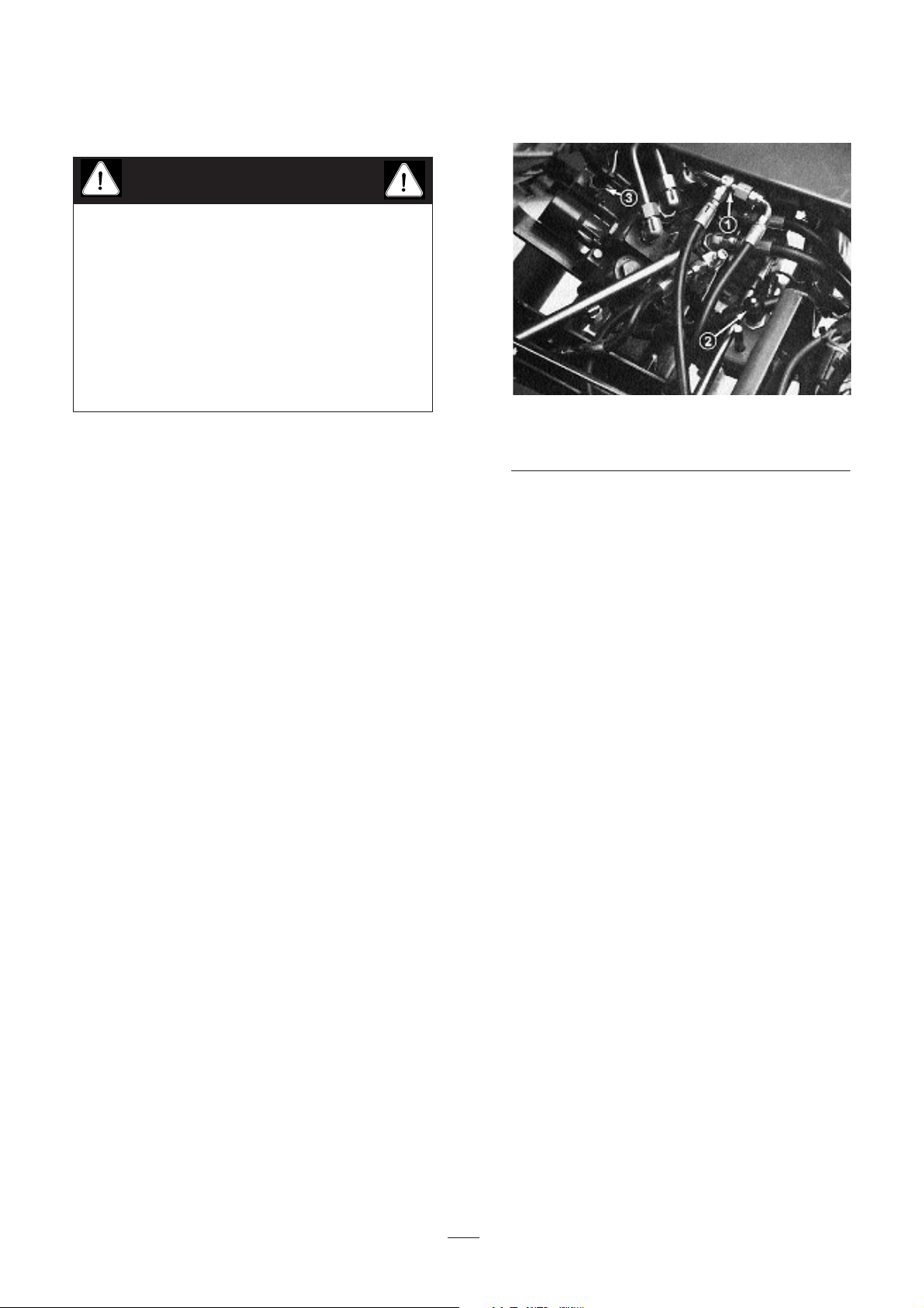
Figure 16
1. Traction switch
2. Seat switch
3. Mow/lift switch
5. Sit on the seat, move the shift selector to neutral,
depress the lift pedal and release it. Start the
engine and depress the mow pedal. Carefully
rise off the seat; the engine should stop. If the
engine stops, the interlock system is operating
correctly. If the engine does not stop, stop the
engine and find the problem before operating the
machine again. If you need assistance, contact
your local TORO distributor.
6. Sit on the seat, move the traction shift selector to
neutral, fully depress the lift pedal and release it.
Start the engine and drive to an open area that is
free of debris and foreign objects. Keep all
people, especially children, away from the front
of the machine and out of the area of operation.
Move the shift selector to neutral, make sure the
mow pedal is disengaged, set the throttle control
at half speed and engage the parking brake. (Do
not engage the parking brake button.) Hold the
steering wheel, brace your feet on the foot deck
and brake pedal, and move the shift selector to
the #1 position. Carefully rise off the seat; the
engine should stop. If the engine stops, the
interlock system is operating correctly.
7. Repeat this check with the shift selector in the #2
position. If the engine does not stop, stop the
engine and find the problem before operating the
machine. If you need assistance, contact your
local TORO dealer.
Note: The Greensmaster 3100 is equipped with
an interlock switch on the parking brake. The
The interlock switches are for the operator’s
protection, so do not disconnect them. Check
switch operation daily to assure the interlock
system is operating. If a switch is defective,
replace it before operating. Regardless of whether
the switches are operating properly, replace them
every two years to assure maximum safety. Do
not rely entirely on safety switches—use common
sense!
CAUTION
Page 20
20
engine will stop if the traction shift selector is in
#1 or #2 positions with the parking brake
engaged.
Check the Leak Detector
Operation
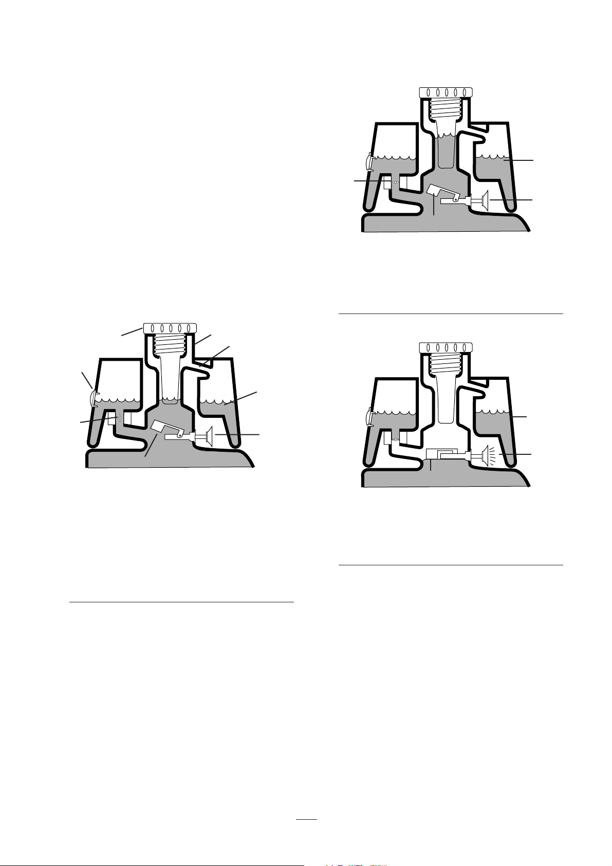
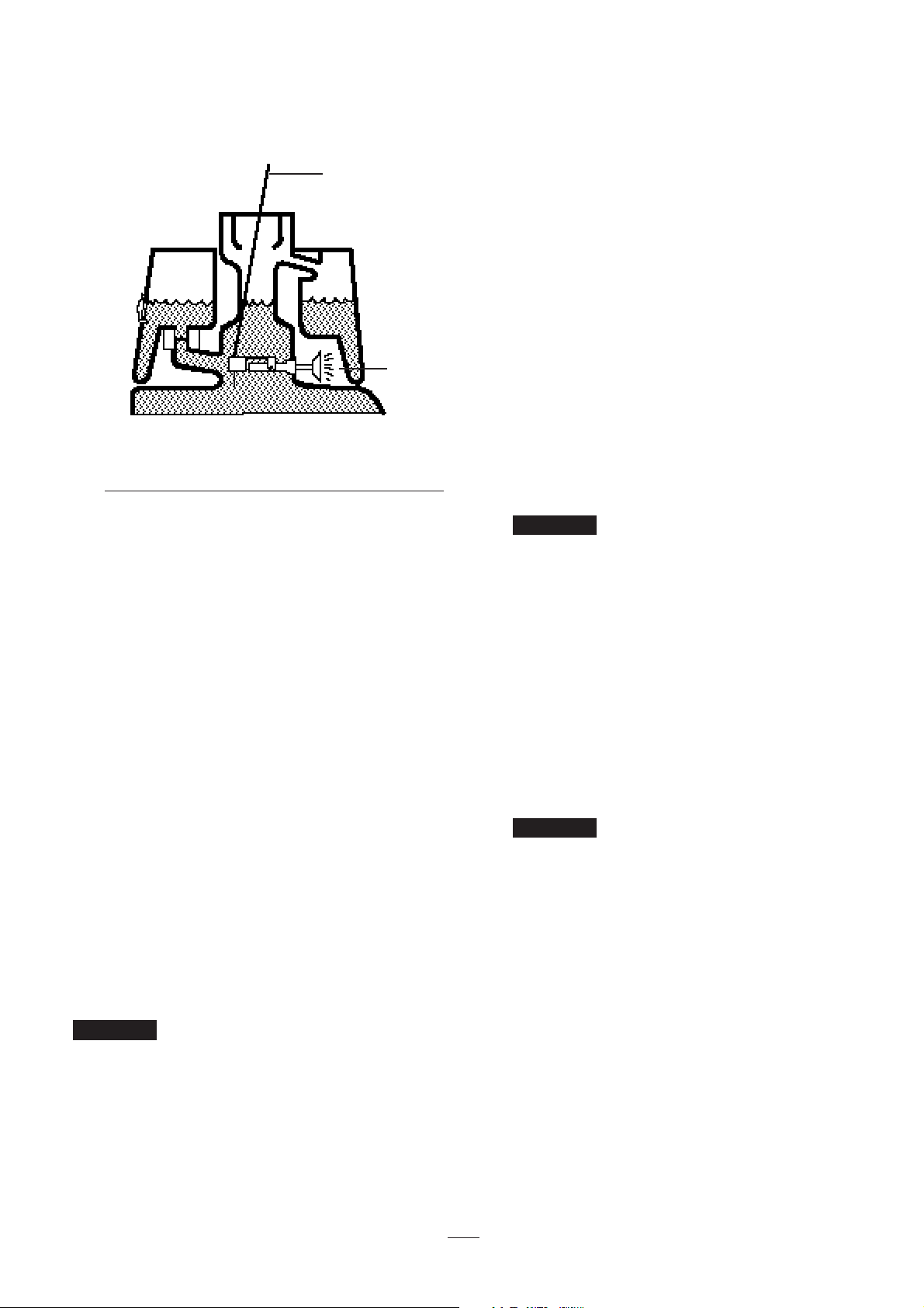
The TURF GUARDIAN™ leak detector detects
hydraulic oil system leaks. If the oil level in the main
hydraulic reservoir is lowered by 12–18 cl, the float
switch in the tank will close. After a 1-second delay,
the alarm will sound. Expansion of oil, due to normal
heating during machine operation, will cause oil to
transfer into the auxiliary oil reservoir. The oil is
allowed to return to the main tank when the ignition
switch is turned off.
Figure 17
BEFORE START (cold oil)
1. Sight window
2. Solenoid return valve open
3. Filler cap
4. Filler neck
5 Overflow tube
6. Fluid level (cold)
7. No sound
8. Float raised, switch open
9. Hydraulic oil tank
To check system operation
1. With the ignition switch in the ON position,
move the leak detector switch rearward and hold.
After the one-second time delay elapses, the
alarm should sound.
2. Release leak detector switch.
Figure 18
NORMAL OPERATION (oil warm)
1. Solenoid return valve closed
2. Fluid level (warm)
3. No sound
4. Float raised, switch open
Figure 19
LEAK ALERT!
1. Fluid level (warm)
2. Warning buzzer
3. Float down, switch closed
To check leak detector system operation
1. Move the ignition switch to ON. DO NOT
START THE ENGINE.
2. Remove the hydraulic tank cap and strainer from
the neck of the tank.
3. Insert a clean rod or screw driver into the tank
neck and gently push down on the switch float
(Fig. 20). The alarm should sound after a onesecond delay.
4. Release the float; the alarm should stop.
3
1
2
1
9
2
5
8
3
4
6
7
1
2
3
4
Page 21
21
5. Install the strainer screen and the hydraulic tank
cap. Move the ignition switch to OFF.
Figure 20
1. Clean the rod or screwdriver
2. Warning buzzer
3. Press down on the switch float
Preparing the Machine for
Mowing
To help align the machine for successive cutting
passes, do the following to the No. 2 and No. 3
cutting-unit baskets:
1. Measure in approximately 12 cm from the outer
edge of each basket.
2. Either place a strip of white tape or paint a line
onto each basket paralleling the outer edge of
each basket (Fig. 21).
Training Period
Before mowing greens with the Greensmaster 3100,
we suggest that you find a clear area and practice
starting and stopping, raising and lowering the cutting
units, turning, etc. This will help you gain confidence
in the performance of the Greensmaster 3100.
If you shift to t
he No. 2 position while
cutting greens, no increase in speed will result.
However, a sudden Increase In speed will develop
when you actuate the lift pedal. For safety, use only
the No. 1 position for cutting greens and the No. 2
position for transport.
Before Mowing
Inspect the green for debris, remove the flag from the
cup, and determine the best direction in which to
mow. Base the direction to mow on the previous
mowing direction. Always mow in an alternate
pattern from the previous mowing, so that the grass
blades will be less apt to lay down and become
difficult to trap between the reel blades and bedknife.
Mowing Procedures
1. Approach the green with the shift selector in the
number 1 position. Start on one edge of the
green so the ribbon procedure of cutting may be
used. This holds compaction to a minimum and
leaves a neat, attractive pattern on the greens.
Shift to the No. 1 position when
approaching a green because machine speed will
automatically be reduced when the cutting units
are engaged. Higher speed will resume when the
cutting units are disengaged.
2. Actuate the mow pedal as the front edge of the
grass baskets cross the outer edge of the green.
This procedure drops the cutting units to the turf
and starts the reels.
NOTE: The No. 1 (rear) cutting unit reel will not
start until all the cutting units are on the ground
and No. 2 and No. 3 cutting units are cutting.
Remember that the No. 1 cutting
unit reel is delayed and therefore, you should
practice to gain the timing necessary to minimize
the clean-up mowing operation.
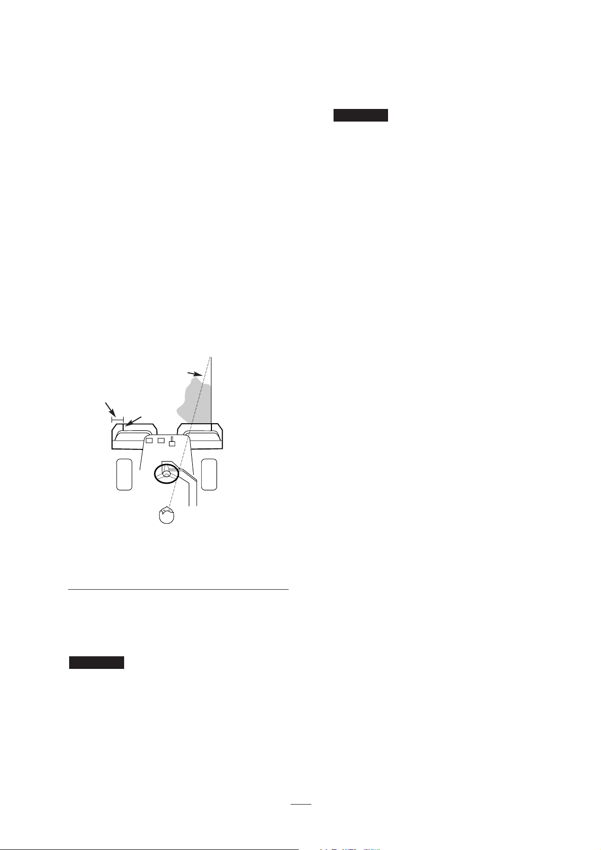
3. Overlap a minimal amount with the previous cut
on return passes. To maintain a straight line
across the green and keep the machine an equal
distance from the edge of the previous cut,
establish an imaginary sight line 2 to 3 meters
ahead of the machine to the edge of the uncut
portion of the green (Fig. 21). Some people find
it useful to include the outer edge of the steering
wheel as part of the sight line; i.e., keep the
steering wheel edge aligned with a point that is
always kept the same distance away from the
front of the machine (Fig. 21).
Important
Important
Important
3
1
2
Page 22
22
4. As the front of the baskets cross the edge of the
green, depress the lift pedal. This will stop the
reels and lift the cutting units. Timing of this
procedure is important, so the mowers do not cut
into the fringe area. However, as much of the
green as possible should be cut to minimize the
amount of grass left to mow around the outer
periphery.
5. Cut down on operating time and ease line-up for
the next pass by momentarily turning the
machine in the opposite direction, then turning in
the direction of the uncut portion; i.e., if
intending to turn right, first swing slightly left,
then right. This will help get the machine more
quickly aligned for the next pass. Follow the
same procedure for turning in the opposite
direction. It’s good practice to try to make as
short a turn as possible. However, turn in a
wider arc during warmer weather to avoid
bruising the turf.
Figure 21
1. Alignment strip
2. Approximately 12 cm
3. Cut grass on right
4. Keep focal spot 2–3 meters ahead of the machine
NOTE: Due to the nature of the power steering
system, the steering wheel will not return to its
original position after a turn has been completed.
Never stop on a green with the
cutting unit reels operating because you may
damage the turf. Stopping on a wet green with
the Greens–master 3100 may leave marks or
indentations from the wheels.
6. If the leak detector alarm sounds while cutting on
a green, immediately raise the cutting units, drive
directly off the green and stop the machine in a
area away from the green. Find out what caused
the alarm and correct the problem.
Prolonged idling of the machine
after heavy use may cause a false alarm in the
leak detector system, due to oil contraction as it
cools. If this occurs, turn the engine off for a
minute while the main hydraulic tank is refilled
from the auxiliary tank.
7. Finish cutting the green by mowing the outer
periphery. Be sure to change the direction of
cutting from the previous mowing. Always keep
weather and turf conditions in mind and be sure
to change the direction of mowing from the
previous cutting. Replace the flag.
8. Empty the grass baskets of all clippings before
transporting to the next green. Heavy wet
clippings place an undue strain on the baskets
and will add unnecessary weight to the machine,
thereby increasing the load on the engine,
hydraulic system, brakes, etc.
Leak Detector Operation
The leak detector alarm may sound for one of the
following reasons:
1. A leak has occurred.
2. The oil level in the main reservoir is reduced by
12–18cl due to oil contraction from cooling.
If the alarm sounds, turn it off as quickly as possible
and inspect for leaks. If the alarm sounds while
operating on a green, drive off the green first.
Determine the source of the leak and repair it before
continuing operation. If a leak is not found and a
false leak is suspected, move the ignition switch to
OFF and let the machine stand for 1–2 minutes to
allow the oil levels to stabilize. Then start the
machine and operate in a non-sensitive area to
confirm that no leak exists.
False alarms due to oil contraction may be caused by
extended idling after normal operation. A false alarm
may also occur if the machine is worked at a reduced
work load after an extended period of heavier work.
To avoid false alarms, turn the machine off rather than
letting it idle for extended periods.
Important
Important
2
1
4
3
Page 23

23
Transport Operation
Make sure the cutting units are in the highest UP
position. Set the shift selector in No. 2 if conditions
will permit faster ground speed. In rough or hilly
areas, shift to No. 1 and operate at slower ground
speeds. Use the brakes to slow the machine while
going down steep hills to avoid loss of control.
Always approach rough areas at a reduced speed (shift
selector in No. 1), and cross severe undulations
carefully. Familiarize yourself with the width of the
machine. Do not attempt to pass between objects that
are close together so that you can prevent costly
damage and down time.
Inspection and Clean-Up After
Mowing
After mowing, thoroughly wash the machine. Use a
garden hose without a nozzle so excessive water
pressure doesn’t contaminate and damage seals and
bearings. After cleaning, inspect the machine for
possible hydraulic fluid leaks, damage or wear to the
hydraulic and mechanical components. Also check
the cutting units for sharpness. Lubricate the mow
and lift pedal and the brake shaft assembly with SAE
30 oil or spray lubricant to deter corrosion and keep
the machine performing well during the next mowing
operation.
Page 24
24
Maintenance
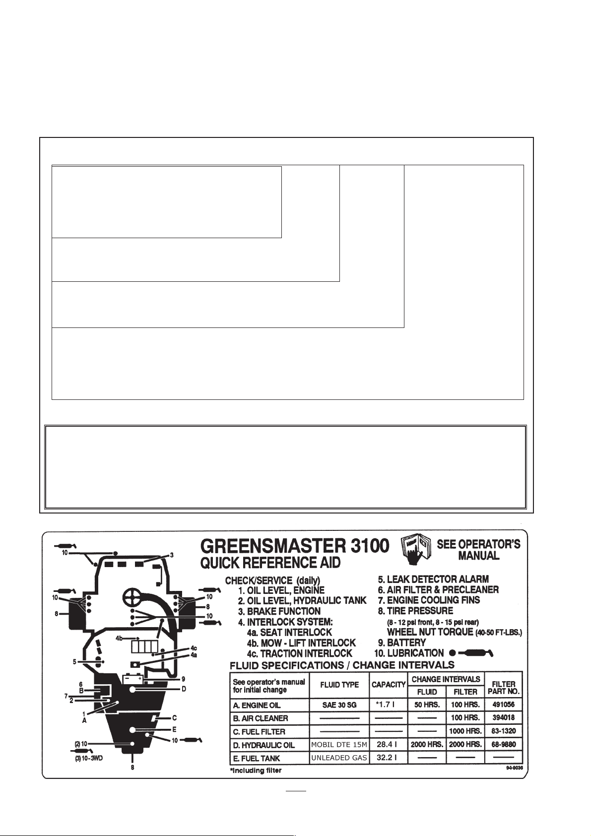
Maintenance Procedure Maintenance Interval & Service
✝ Initial break in at 8 hours
Replace the spark plugs
Replace the fuel filter
Check valve clearance
Check the engine RPM (idle and full throttle)
Maintenance Schedule
Replace moving hoses
Replace safety switches
Fuel tank—drain and flush
Hydraulic tank—drain and flush
Replace the hydraulic oil
Check the reel bearing preload adjustment
Torque the wheel lug nuts
✝Replace the engine oil filter
Replace the air filter element
Check battery fluid level
Check battery cable connections
Service the air filter pre-cleaner
Lubricate all grease fittings
✝Change the engine oil
Every
800
hours
Every
200
hours
Every
100
hours
Every 50
hours
Recommendations
Items are recommended every 2000 hours
or 2 years, whichever occurs first.
Page 25

25
Daily Maintenance Checklist
✓ Safety Interlock Operation
✓ Brake Operation
✓ Engine Oil & Fuel Level
✓ Cooling system Fluid Level
✓ Radiator & Screen for Debris
✓ Unusual Engine Noises
✓ Unusual Operating Noises
✓ Hydraulic System Oil Level
✓ Hydraulic Hoses for Damage
✓ Fluid Leaks
✓ Tire Pressure
✓ Instrument Operations
✓ Lubricate All Grease Fittings
✓ Touch-up Damaged Paint
Page 26
26
Lubrication
Before servicing or making adjustments to the
machine, stop the engine and remove the key from the
switch.
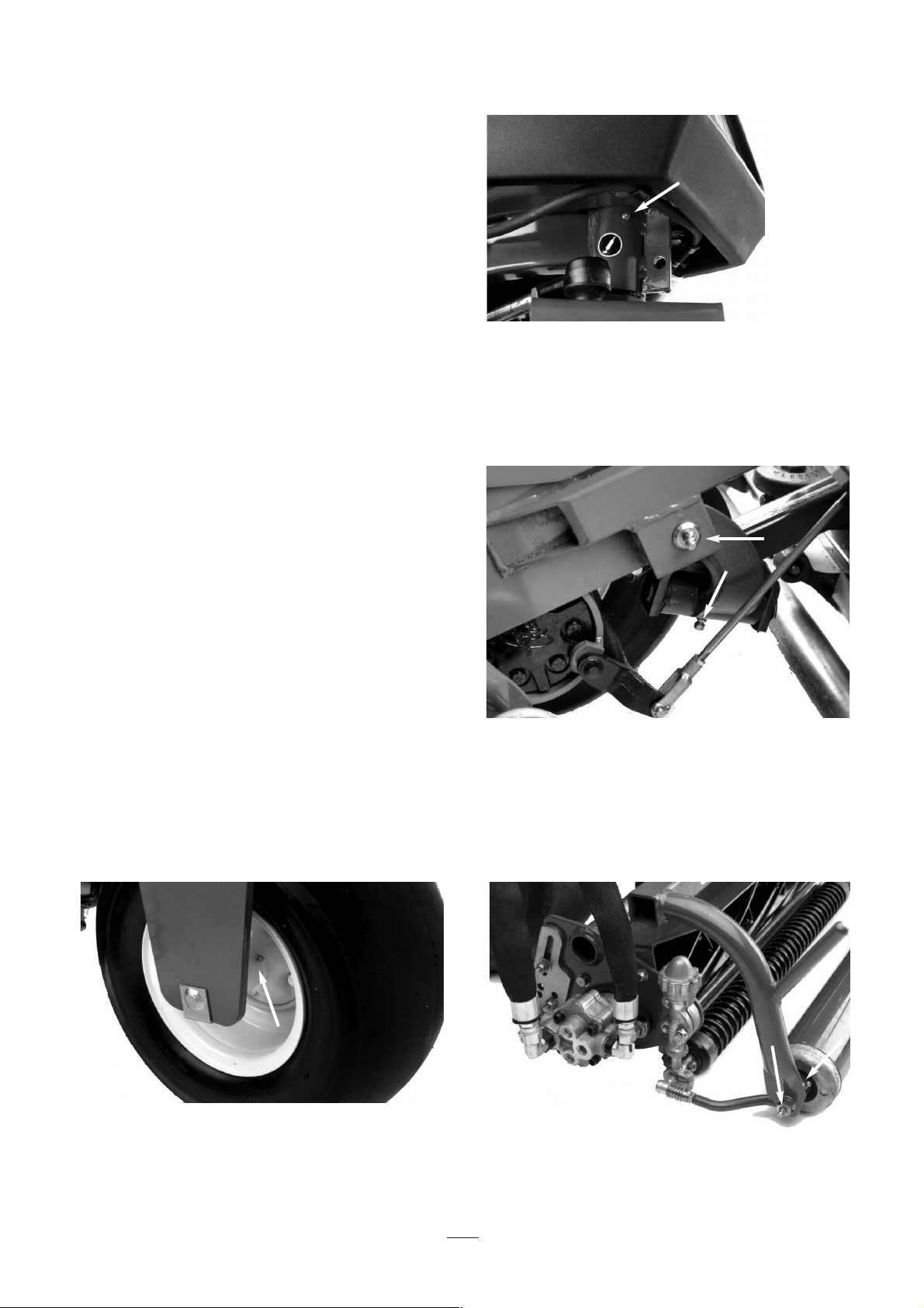
The traction unit has grease fittings that must be
lubricated regularly with No. 2 General Purpose
Lithium Base Grease. If the machine is operated
under normal conditions, lubricate all bearings and
bushings after every 50 hours of operation.
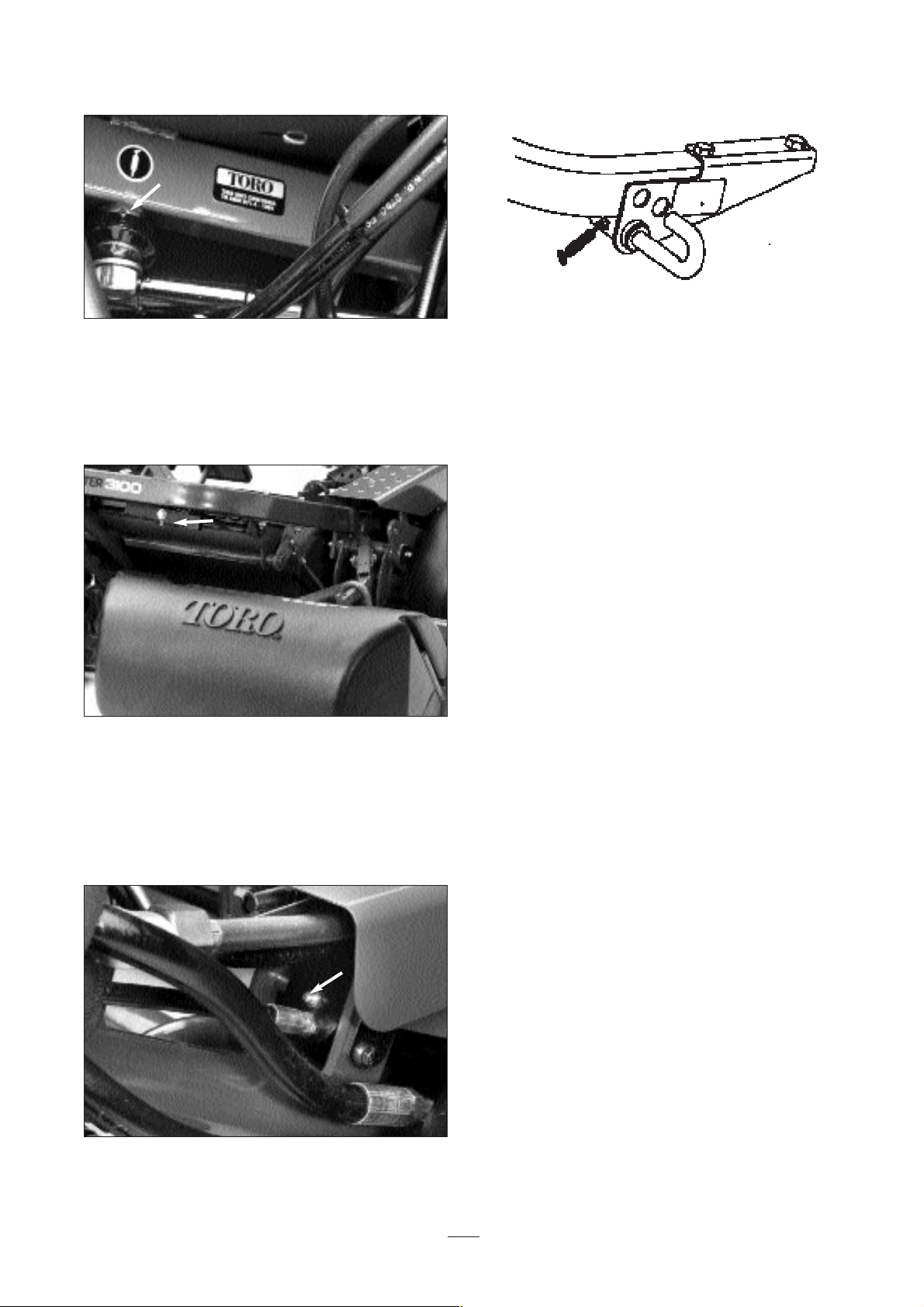
The traction unit bearings and bushings that must be
lubricated are: Rear wheel roller clutches and external
ball bearing (1) (Fig. 22), Steering fork shaft (1) (Fig.
23), Lift arm pivot (3), Pivot hinge (3) (Fig. 24), Pull
frame shaft and roller (12) (Fig. 25), Power steering
cylinder (1) (Fig. 26), Mow lift pivot (1) (Fig. 27),
Lift cylinders (3) (Fig. 28) and Mow lockout lever
(Fig. 29).
1. Wipe grease fittings clean so foreign matter
cannot be forced into the bearing or bushing.
2. Pump grease into the bearing or bushing.
3. Wipe up excess grease.
4. Apply grease to the reel motor spline shaft and
onto the lift arm when the cutting unit is removed
for service.
5. Apply a few drops of SAE 30 engine oil or spray
lubricant (WD 40) to all pivot points daily after
cleaning.
Figure 22
Figure 24
Figure 23
Figure 25
Page 27
27
Figure 27
Figure 29
Figure 28
Figure 26
Page 28
28
Changing the Engine Oil and
Filter
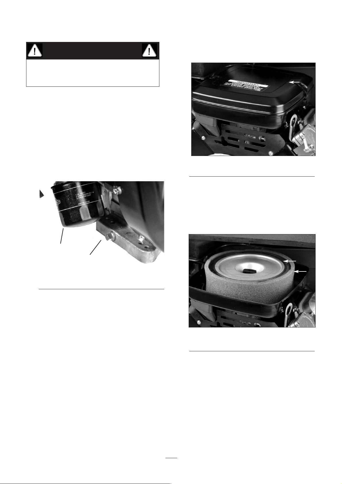
Change the oil and filter initially after the first 8 hours
of operation, thereafter change the oil every 50 hours
and the filter every 100 hours.
1. Remove the drain plug and let oil flow into a
drain pan. When oil stops flowing, install the
drain plug.
Figure 30
1. Drain plug
2. Oil filter
2. Remove the oil filter. Apply a light coat of clean
oil to the new filter gasket.
3. Screw the filter on by hand until the gasket
contacts the filter adapter, then tighten 1/2 to 3/4
turn further. DO NOT OVER-TIGHTEN.
4. Add oil to the crankcase, refer to CHECK
ENGINE OIL.
5. Dispose of oil properly.
Servicing the Air Cleaner
Service the air cleaner foam pre-cleaner after every 50
operating hours and the air cleaner cartridge after
every 100 operating hours. More frequent cleaning is
required when operating in dusty or dirty conditions.
1. Release the locking clips and remove the air
cleaner cover. Clean the cover thoroughly.
Figure 31
1. Air cleaner cover
2. Remove the wing nut securing the elements to
the air cleaner body.
3. If the foam element is dirty, remove it from the
paper element. Clean thoroughly.
Figure 32
1. Foam element
2. Paper element
A. WASH the foam element in a solution of
liquid soap and warm water. Squeeze to
remove dirt, but do not twist because the
foam may tear.
B. DRY by wrapping the element in a clean
cloth. Squeeze the cloth and foam element
to dry.
2
1
2
1
1
Before servicing or making adjustments to the
machine, stop the engine and remove the key from
the switch.
CAUTION
Page 29
29
C. SATURATE the element with clean engine
oil. Squeeze the element to remove excess
oil and to distribute oil thoroughly. An oil
damp element is desirable.
4. When servicing the foam element, check the
condition of the paper element. Clean by gently
tapping on a flat surface or replace as required.
5. Reinstall the foam element, paper element and
the air cleaner cover.
Do not operate the engine without
the air cleaner element because extreme engine
wear and damage will likely result.
Adjusting the Throttle Control
Proper throttle operation depends on proper throttle
control adjustment. Before adjusting the carburetor,
assure the throttle control is operating properly.
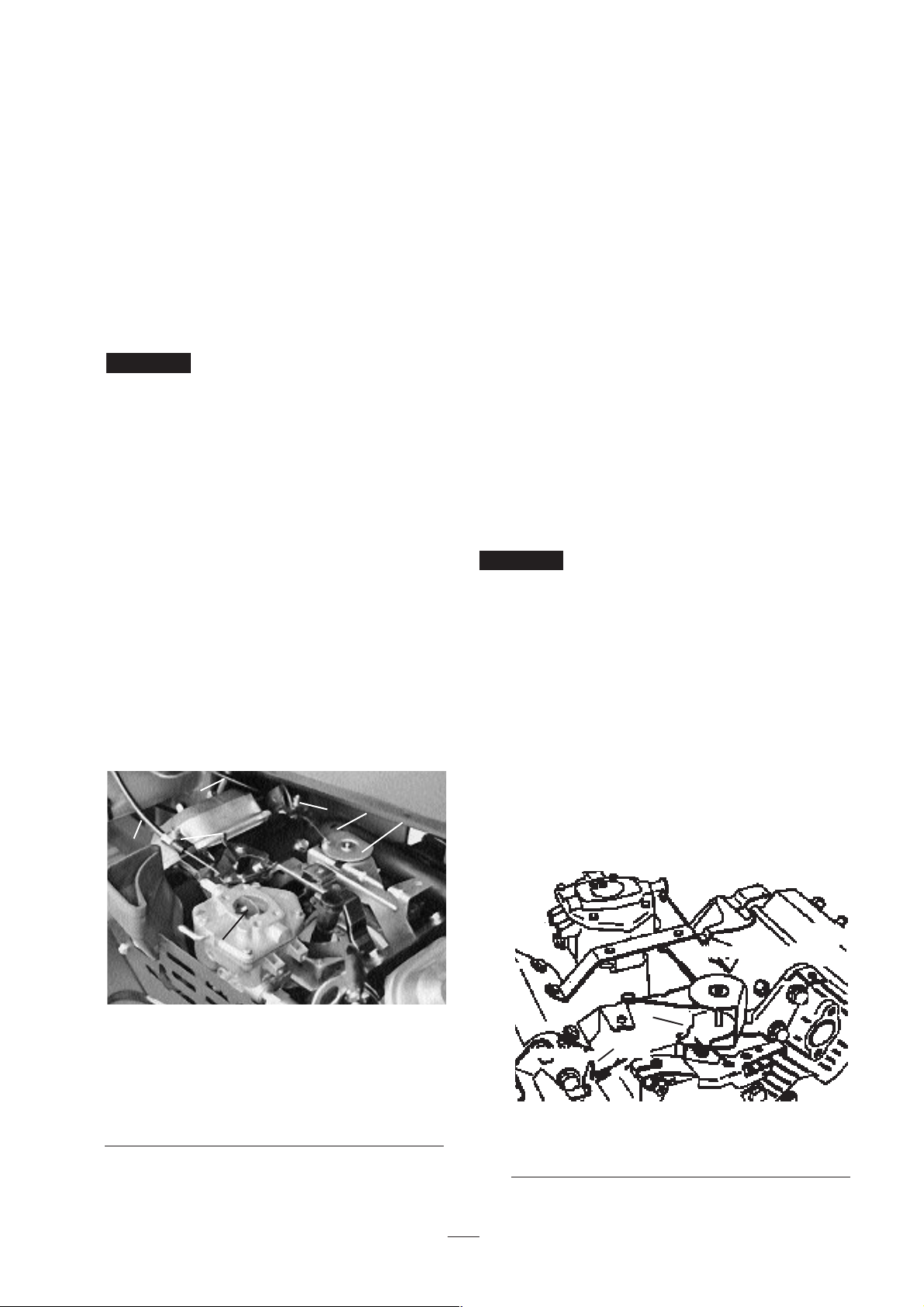
1. Loosen the cable clamp screw securing the cable
to the engine.
2. Move the remote throttle control lever forward to
the FAST position.
3. Pull firmly on the throttle cable until the back of
the swivel contacts stop.
Figure 33
1. Throttle casing clamp screw
2. Throttle cable
3. Swivel
4. Stop
5. Choke casing clamp screw
6 Choke cable
7. Choke butterfly
4. Tighten the cable clamp screw and check the
engine RPM setting.
High Idle: 2850 ± 50 rpm
Low Idle: 1400 ± 50 rpm
Adjusting the Choke Control
1. Loosen the cable clamp screw securing the cable
to the engine.
2. Move the remote choke control lever forward to
the CLOSED position.
3. Pull firmly on the choke cable until the choke
butterfly is completely closed, then tighten the
cable clamp screw.
Adjusting Carburetor and Speed
Control
Before the carburetor and speed control
are adjusted, the throttle and choke controls must be
adjusted properly.
The engine must be running during adjustment of
the carburetor and speed control. To guard
against possible personal injury, shift into neutral,
and engage the parking brake. Keep your hands,
feet, face, and other parts of your body away from
the cutter blades and any rotating engine parts.
1. Start the engine and let it run at half throttle for
approximately five minutes to warm up.
Figure 34
1. Governed idle spring anchor tang
2. High-speed spring anchor tang
Important
Important
1
2
5
6
7
3
4
1
2
Page 30
30
2. Move the throttle control to the SLOW setting.
Hold the governor lever so that the throttle lever
is in the idle position (against idle stop screw)
and adjust the idle stop screw to 1400 ± 50 rpm
by turning the screw in or out. Check speed with
a tachometer.
3. Turn the idle mixture screw slowly clockwise
(lean mixture) until the engine speed just starts to
decrease. Note the position of the needle.
Now turn the idle mixture screw slowly
counterclockwise (rich mixture) until the engine
speed just starts to decrease. Note the position
of the needle.
Set the screw midway between the rich and lean
settings.
4. After the idle mixture has been adjusted, hold the
governor lever so the throttle lever is in the idle
position (against the idle stop screw) and readjust
the idle stop screw to bring speed to 1200± 50
rpm.
5. With the governor control lever in the governed
idle position (no tension on high-speed spring)
bend the governed idle spring anchor tang to
attain a governed idle speed of 1400± 50 rpm.
6. Move the throttle control to the FAST position.
Bend the high-speed spring anchor tang to attain
a high speed of 2850 ± 50 rpm.
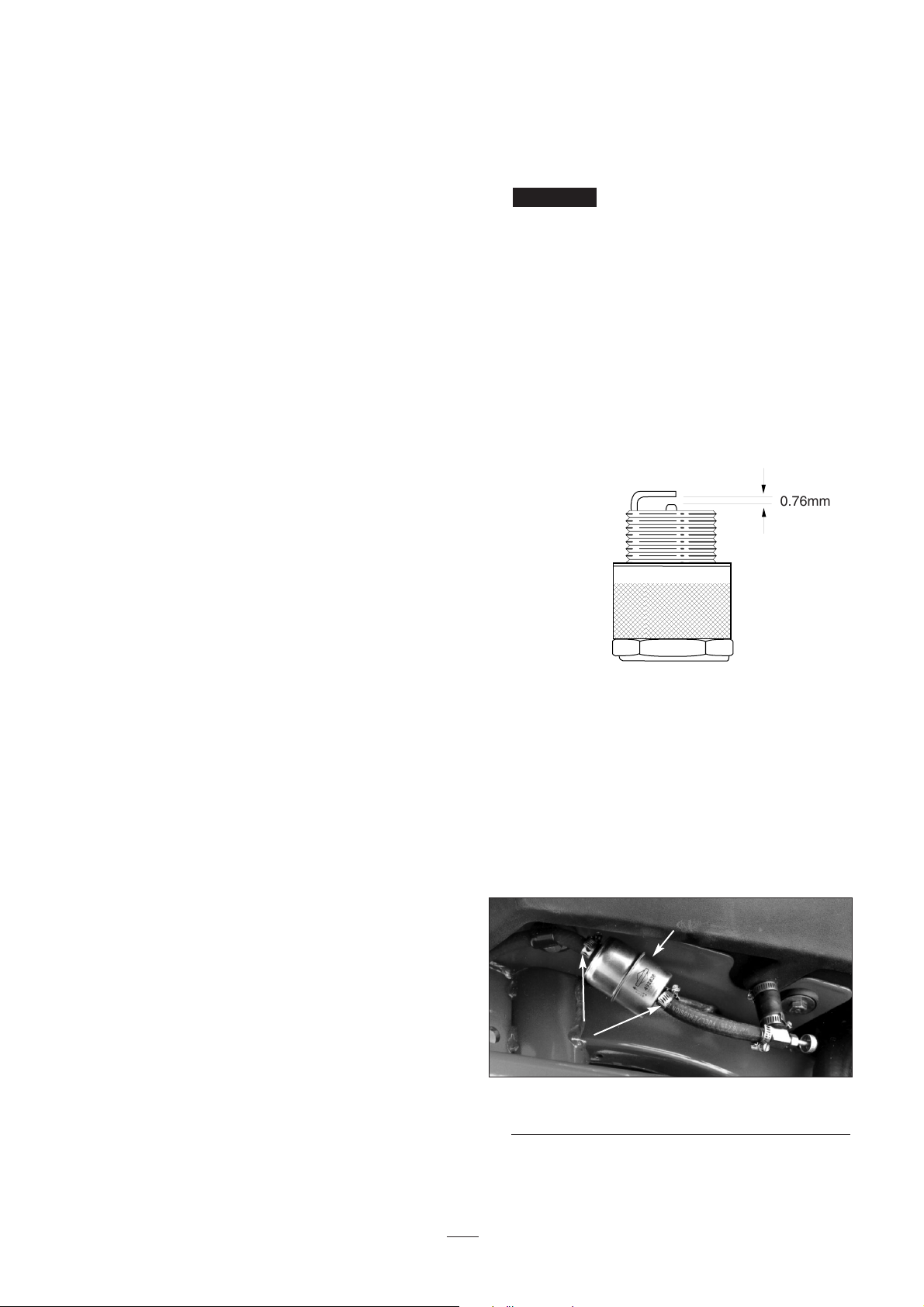
Replacing Spark Plugs
Replace spark plugs after every 800 operating hours.
Recommended air gap is 0.030”.
Correct spark plug is a Champion RC 12YC.
Note: The spark plug usually lasts a long time;
however, the plug should be removed and checked
whenever the engine malfunctions.
1. Clean the area around spark plugs so that foreign
matter cannot fall into the cylinder when you
remove the spark plug.
2. Pull off spark plug wires and remove the plugs
from the cylinder head.
3. Check the condition of the side electrode, center
electrode, and center electrode insulator to assure
there is no damage.
A cracked, fouled, dirty or
otherwise malfunctioning spark plug must be
replaced. Do not sand blast, scrape, or clean
electrodes using a wire brush because grit may
release from the plug and fall into the cylinder.
The result is usually a damaged engine.
4. Set the air gap between the center and side of
electrodes at 0.030”. Install a gapped spark plug
w/gasket seal, and tighten the plug to 200 in-lb.
If you don’t use a torque wrench, tighten the plug
firmly.
Figure 35
Fuel Filter Replacement
An in-line filter is incorporated into the fuel line
between the fuel tank and carburetor. Replace the
filter every 800 hours or sooner if fuel flow is
restricted. Be sure the arrow on the filter is pointing
away from the fuel tank.
Figure 36
1. Fuel filter
2. Hose clamps
Since gasoline is highly flammable, drain it outdoors
and make sure the engine is cool to prevent a fire
Important
1
2
0.76mm
0.3 mm
Page 31
31
hazard. Wipe up any gasoline that may have spilled.
Do not drain gasoline near any open flame or where a
spark may ignite gasoline fumes. Do not smoke a
cigar, cigarette, or a pipe when handling gasoline.
1. Close the fuel shut-off valve, loosen the hose
clamp on the carburetor side of the filter and
remove the fuel line from the filter.
2. Place a drain pan under the filter, loosen the
remaining hose clamp and remove the filter.
3. Install the new filter with the arrow on the filter
body pointing away from the fuel tank.
Changing the Hydraulic Oil and
Filter
Normally, change the hydraulic oil and filter after
every 2,000 operating hours. If the oil becomes
contaminated, contact your local TORO distributor
because the system must be flushed. Contaminated
oil looks milky or black when compared with clean
oil.
1. Remove the drain plug from the reservoir and let
the hydraulic oil flow into a drain pan. Install
and tighten the plug after the hydraulic oil stops
draining.
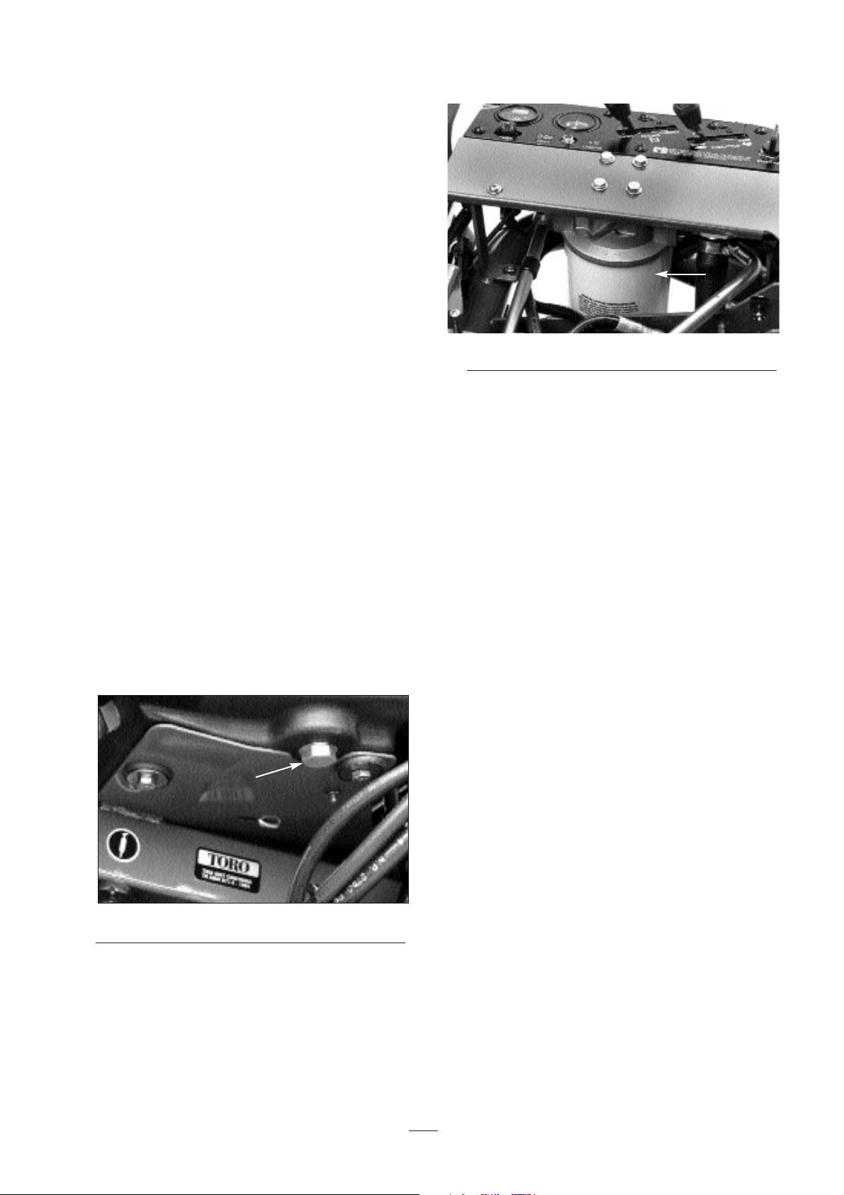
Figure 37
1. Hydraulic Reservoir Drain Plug
2. Clean the area around the filter mounting area.
Place a drain pan under the filter and remove the
filter.
Figure 38
1. Hydraulic Filter
3. Fill the replacement filter with Mobil DTE 15M
hydraulic fluid, lubricate the sealing gasket and
hand turn until the gasket contacts the filter head.
Then tighten 3/4 turn further. The filter should
now be sealed.
4. Fill the large hydraulic tank and small auxiliary
tank with approximately 32l of hydraulic oil.
Refer to Check the Hydraulic System.
5. Start the machine and run it at idle for 3 to 5
minutes to circulate the fluid and remove any air
trapped in the system. Stop the machine and
recheck the fluid level.
NOTE: If the leak detector alarm sounds, turn
the key OFF and wait a few minutes for the oil
level to equalize in the tanks. Recheck the fluid
level and add oil, if required.
6. Dispose of oil properly.
Checking Hydraulic Hoses and
Lines
Check hydraulic lines and hoses daily for leaks,
kinked lines, loose mounting supports, wear, loose
fittings, weather deterioration and chemical
deterioration. Make all necessary repairs before
operating.
1
1
Page 32
32
Brake Adjustment
A brake adjustment rod is located on each side of the
Greensmaster 3100 so the brakes can be equally
adjusted. Adjust the brakes as follows:
1. Transport the Greensmaster 3100 and depress the
brake pedal; both wheels should lock equally.
2. If the brakes don’t lock equally, disconnect the
brake rods by removing the cotter pin and clevis
pin.
3. Loosen the jam nut and adjust the clevis
accordingly.
Figure 39
1. Clevis pin & cotter pin
2. Jam nut
3. Clevis
4. Brake shaft
4. Assemble the clevis to the brake shaft.
5. Check the amount of free travel of the brake
pedal when adjustment is completed. There
should be 1.2–2.5 cm travel before the brake
shoes make contact with the brake drums.
Re-adjust, if necessary, to achieve this setting.
6. Transport the Greensmaster 3100 and depress the
brake pedal; both brakes should lock equally.
Readjust them, if necessary.
7. Burnish brakes annually, refer to Break-in
Period.
Rear Camshaft Adjustment
A camshaft misaligned with the valve bank may cause
the following:
A. No increase in ground speed in No. 2 (transport)
traction selection.
B. The mow pedal will not stay depressed (in
detent) without foot pressure.
C. Slow lift of the cutting units.
D. Slow or no drive to the cutting units.
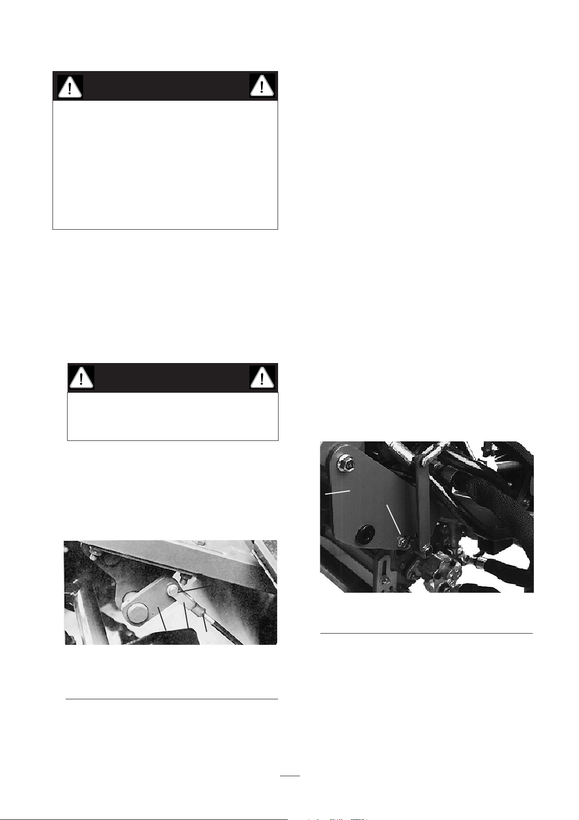
Figure 40
1. Mounting capscrews
2. Cam blocks
1. If one or more malfunctions occur, loosen the
rear camshaft mounting capscrews and relocate
the cam shaft until the condition is corrected.
2. Retighten the capscrews.
You must readjust the mow/lift switch when the
camshaft adjustment is completed and the lift and
Keep your body and hands away from pin-hole
leaks or nozzles that eject high-pressure hydraulic
fluid. Use cardboard or paper to find hydraulic
leaks. Hydraulic fluid escaping under pressure
can penetrate skin and cause injury. Fluid
accidentally injected into the skin must be
surgically removed within a few hours by a doctor
familiar with this form of injury or gangrene may
result.
CAUTION
As a safety precaution, always check brakes in
a wide, open-spaced, flat area that is free of
other persons and obstructions.
CAUTION
1
2
3
4
2
1
Page 33
33
mow pedal height.
Adjusting the Lift and Mow Pedal
Height
Adjust the lift and mow pedal to equal height to gain
proper spool travel in the valve bank as follows:
1. Place 1, 2 and 3 spools in neutral (center of
travel) and remove the transfer rod guard from
the foot panel.
2. Loosen the jam nut securing the yoke on the
front of the long control rod; remove the cotter
pin and clevis pin.
3. Move the adjustment lever by hand to level the
mow and lift the pedals and adjust the yoke on
the control rod until the hole in the yoke lines up
with the adjustment lever hole.
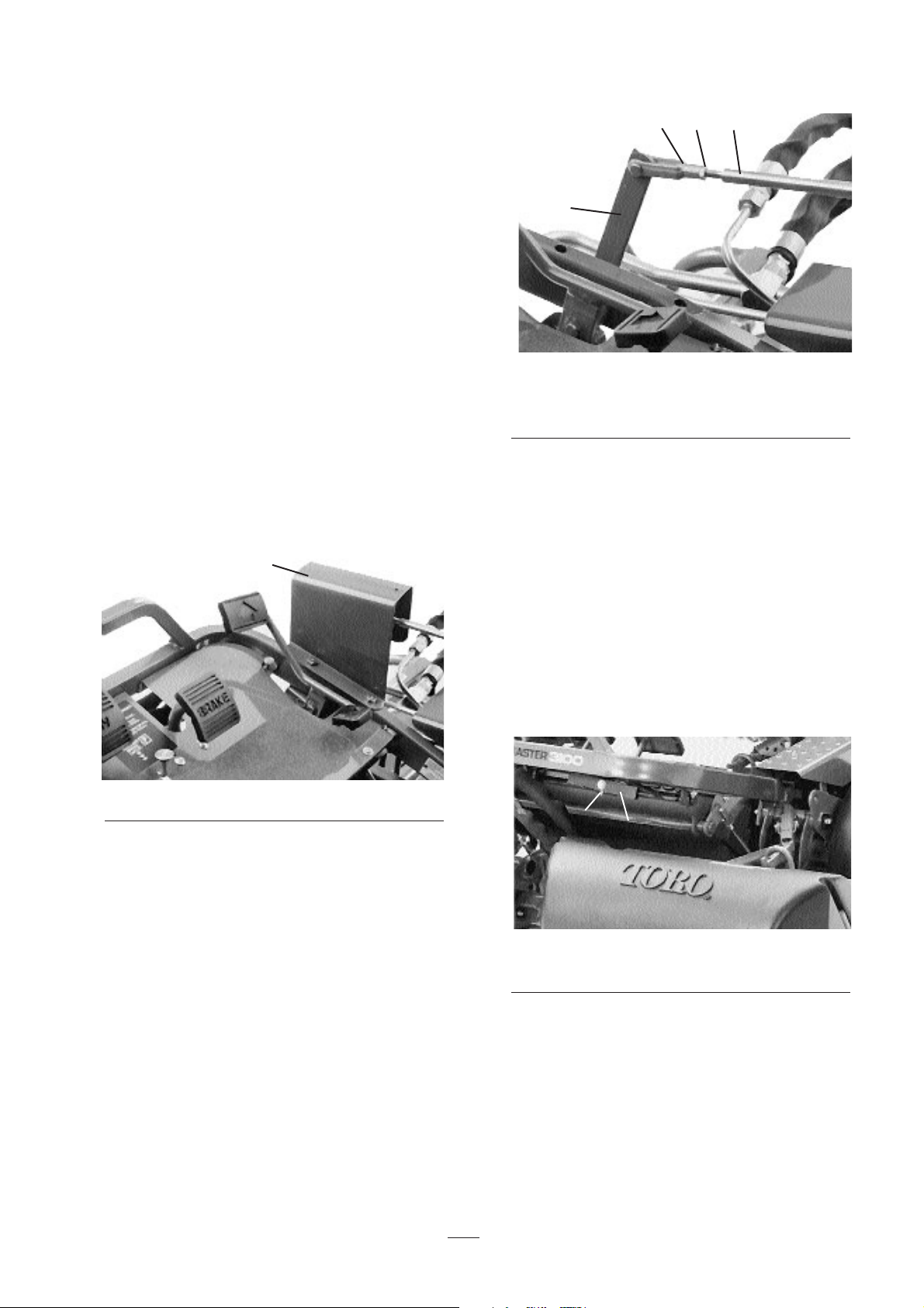
Figure 41
1. Transfer rod guard
4. Install the clevis pin and cotter pin. Tighten the
jam nut and install the transfer rod guard.
5. Actuate the mow pedal by hand. Be sure the lift
pivot under the pedals clears the stop welded to
the frame, thereby allowing full spool travel.
Figure 42
1. Jam nut
2Yoke
3. Control rod
4. Adjustment lever
Leveling the Lift and Mow Pedals
If the lift and mow pedals are not level when in the
neutral position, an adjustment to the lift pivot is
required.
1. Loosen the nut on the back side of the lift pivot.
2. Rotate the eccentric screw to raise or lower the
lift pivot spring, leveling the lift pivot and
pedals.
Figure 43
1. Lift Pivot
2. Eccentric Screw
3. While holding the screw, tighten the nut to lock
the adjustment.
Adjusting the Traction Pedal
To check forward and reverse operation of the traction
pedal, proceed as follows:
1
1
2
3
4
2
1
Page 34
34
Forward
1. Press the traction pedal fully forward until the
No. 5 section, valve spool is completely pulled
out.
2. The pedal should contact the pedal stop. If the
pedal contacts the stop before the spool is
completely out, or if the pedal does not make
contact with the stop, the stop must be adjusted.
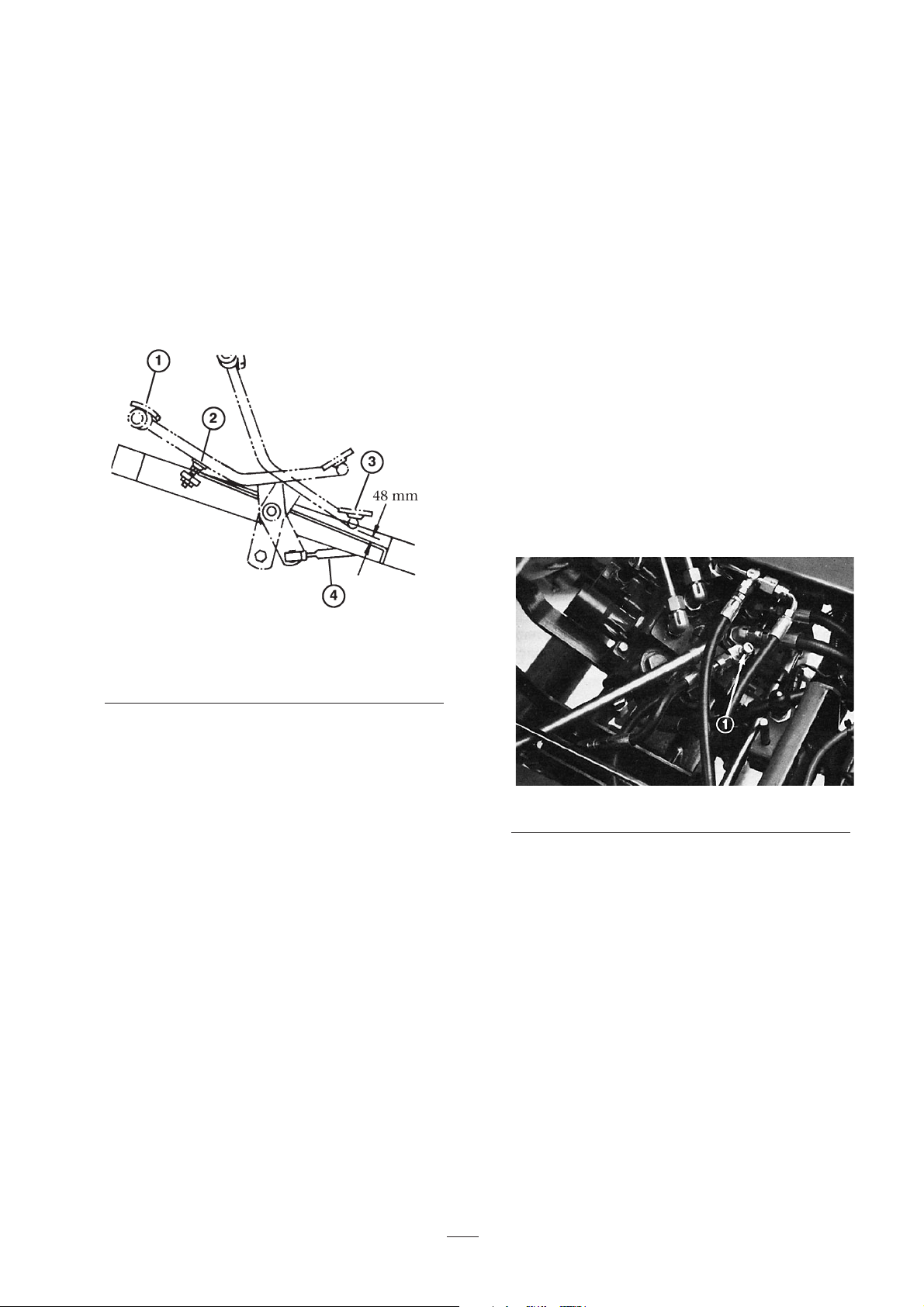
Figure 44
1. Fully forward
2. Pedal stop
3. Reverse
4. Control rod
3. Loosen the hex nut securing the threaded rod to
the frame. Turn the flange nut on the rod to raise
or lower the stop (rod), while checking the pedal.
4. When completed, tighten the nut.
Reverse
1. Press down on the rear of the traction pedal
(reverse) until the No. 5 section spool valve is
completely pushed in.
2. Check the distance between the bottom of the
pedal and the footrest, as shown in Fig. 48.
Distance should be approximately 4.8mm. If the
distance is greater or less than 4.8mm, an
adjustment to the traction control rod is required.
3. Remove the jam nut and ball joint securing the
control rod to the traction shaft pivot.
4. Loosen the jam nuts securing the ball joints to
the control rod and adjust the ball joints and
control rod to attain 4.8mm dimension when
reinstalled.
Adjusting the Cutting Unit
Lift/Drop
1. The machine’s cutting unit lift/drop circuit is
equipped with a flow control valve. This valve is
pre-set at the factory at approximately 3-1/2 turns
open, but an adjustment may be required to
compensate for differences in hydraulic oil
temperatures, mowing speeds, etc. If an
adjustment is required, proceed as follows:
Note: Allow hydraulic oil to reach full operating
temperature before adjusting the flow control
valve.
2. Raise the seat and locate the flow control valve
mounted to the main control valve.
Figure 45
1. Flow control valve
3. Loosen the jam nut retaining the adjusting knob
on the flow control. When loosening the jam nut,
hold the flow control knob to prevent it from
rotating.
4. Rotate the knob 1/4 turn counterclockwise if the
center cutting unit is dropping too late or turn it
1/4 turn clockwise if the center cutting unit is
dropping too early.
5. After achieving the desired setting, hold the knob
to prevent any further rotation and tighten the
jam nut.
Page 35
35
Adjusting the Lift Cylinders
To regulate the height of the front cutting units when
in the raised (transport) position, the front lift
cylinders may be adjusted.
1. Lower the cutting units to the floor.
2. Loosen the jam nut on the clevis of the cutting
unit lift cylinder you wish to adjust.
3. Disconnect the cylinder clevis from the lift arm.
4. Rotate the clevis until you attain the desired
height.
5. Connect the cylinder clevis to the lift arm and
tighten the jam nut.
Seat Switch Maintenance
1. Pivot the seat forward and secure it with the
support rod to prevent it from falling accidentally
and causing injury.
2. Remove the boot from the button end of the seat
switch and retain it for installation on the
replacement switch. Unplug the switch
connectors.
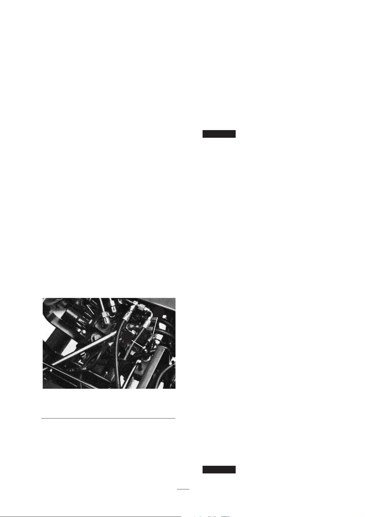
Figure 46
1. Traction switch
2. Seat switch
3. Mow/lift switch
3. Loosen the jam nut and unscrew the switch from
the mounting bracket.
4. Screw the new switch through the mounting
bracket until the switch button is about 1.6mm
shorter than the top of the seat return spring pin.
Install the boot into the mount grooves.
5. Carefully release the seat to its normal down
position, but do not sit or apply force on the seat.
There should be a slight gap between the switch
and the seat plate.
6. Lock the switch in place by tightening the jam
nut to 75 in-lb against the mounting bracket.
Switch threads will be damaged if
the jam nut is over-tightened.
7. Connect a continuity tester or ohm meter to the
switch terminals. With the seat in the down
position and no one on the seat, the switch circuit
should not have continuity. If there is continuity,
repeat steps 4–6. If there is no continuity, go to
step 8.
8. Sit on the seat. The seat switch should have
continuity. If there is no continuity, repeat steps
4–7. If there is continuity go to step 9.
9. Plug the switch connectors together.
Traction Switch Maintenance
1. Pivot the seat forward and secure it with the
support rod to prevent it from failing accidentally
and causing injury.
2. Unplug the switch connectors from the traction
switch installed in the valve bank bonnet on the
selector valve section.
3. Loosen the jam nut and unscrew the switch from
the mounting bracket.
4. Move the shift selector to neutral.
5. Partially screw the new switch into the bonnet.
6. Connect a continuity tester or ohm meter to the
switch terminals and continue to turn the switch
in until there is continuity. Then rotate the
switch in 1/2 turn (180 degrees).
7. Secure the jam nut to 75 in-lb. against the
bonnet.
Switch threads will be damaged if
Important
Important
3
1
2
Page 36
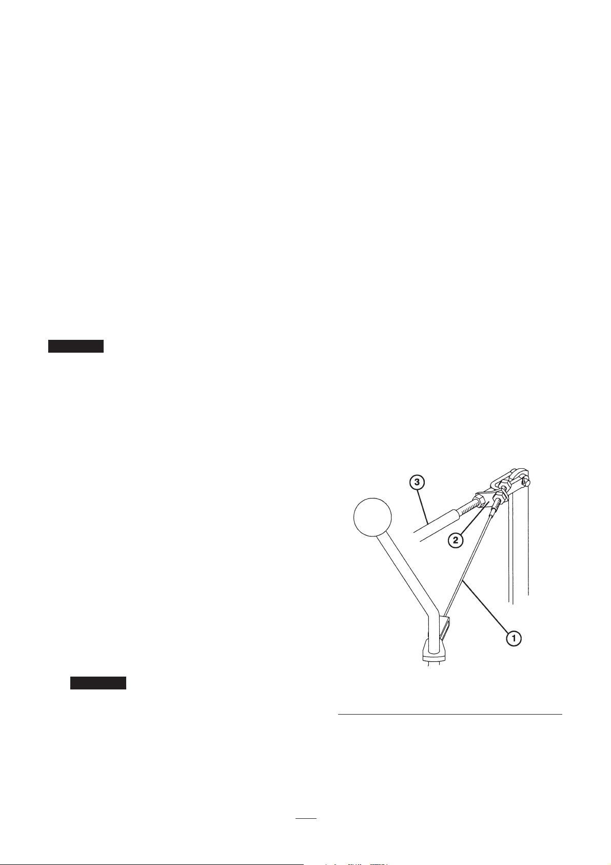
36
the jam nut is over-tightened.
8. Connect a continuity tester or ohm meter to the
switch terminals and move shift selector to the
#1 and #2 positions. There should not be
continuity when the shift selector is in either of
these positions. If there is continuity, repeat
steps 5 and 6.
9. Move the shift selector lever to neutral and
connect a continuity tester or ohm meter to the
switch terminals. The switch should show
continuity. This means the switch is operating
correctly.
10. Plug the switch connectors together.
Mow/Lift Switch Maintenance
Spool travel for 1, 2 and 3 spools must
be correct before the mow/lift switch can be adjusted.
Refer to Rear Camshaft Adjustment.
1. Pivot the seat forward and secure it with the
support rod to prevent it from falling accidentally
and causing injury.
2. Unplug the switch connectors from the end of the
mow/lift switch installed in the valve bank
bonnet.
3. Loosen the jam nut and unscrew the switch from
the valve bank bonnet.
4. While holding the lift pedal in a fully depressed
position (valve bank spools fully IN), partially
screw the new switch into the bonnet.
5. Connect a continuity tester or ohm meter across
the switch terminals and turn the switch in until
continuity occurs. Then rotate the switch in 1/2
turn (180 degrees) and secure the jam nut to 75
in-lb. against the bonnet.
.
Switch threads will be damaged if
the jam nut is over-tightened.
6. Connect a continuity tester or ohm meter to the
switch terminals and depress the mow pedal.
There should not be continuity. If there is
continuity, repeat step 4. Go to step 7 if there is
no continuity.
7. Depress the lift pedal and release it (neutral
position). The switch circuit should have
continuity.
8. Plug the switch connectors together.
Adjusting the Traction Return
Linkage
If the shift selector lever does not return to the neutral
or #1 position from the #2 position when the mow
pedal is engaged, an adjustment to the traction return
linkage is required.
1. Loosen the front jam nut securing the cable
assembly to the mow/lift control rod bracket.
2. Move the shift lever to the #1 position.
3. While holding the mow/lift control rod in the
rear position, tighten the rear locknut to remove
almost all slack from the cable assembly. Do not
over-tension the cable.
4. Tighten the front jam nut to lock adjustment.
5. Check operation and re-adjust as required.
Figure 47
1. Cable assembly
2. Mow/lift control rod bracket
3. Mow/lift control rod
Battery Care
1. Battery electrolyte level must be properly
maintained and the top of the battery kept clean.
Important
Important
Page 37

37
If the Greensmaster 3100 is stored in a location
where temperatures are extremely high, the
battery will run down more rapidly than if the
machine is stored in a location where
temperatures are cool.
Since the gasses from the battery and the
gasoline fumes are explosive, keep open flame
and electrical sparks away from the area; do not
smoke.
2. Check the electrolyte level every 50 operating
hours or, if the machine is in storage, every 30
days.
3. Maintain cell level with distilled or
demineralized water. Do not fill cells above the
bottom of the split ring inside each cell.
4. Keep the battery top clean by washing it
periodically with a brush dipped in ammonia or
bicarbonate of soda solution. Flush the top
surface with water after cleaning. Do not remove
the fill caps while cleaning.
5. Battery cables must be tight on the battery
terminals to provide good electrical contact.
6. If corrosion occurs at the terminals, disconnect
the cables—negative (–) cable first—and scrape
the clamps and terminals separately. Reconnect
the cables—positive cable first—and coat the
terminals with petroleum jelly.
Page 38

38
2. No #1 or Reverse Traction
speed. Normal #2 speed.
• Defective or missing disc seal
between the #3 or #4 valve
sections.
• Poppet inside #4 spool stuck
open. Off seat.
• Open traction relief cartridge in
the #4 spool section.
• Remove the valve bank.
Replace the disc seal.
• Remove the valve bank.
Repair the #4 spool section.
• Remove the relief cartridge.
Repair or replace it.
CONDITION CAUSE CORRECTION
HYDRAULIC:
1. No ground speed increase in
#2 selection.
• Maladjusted control lever.
• Maladjusted rear camshaft.
• Mow-lift linkage binding or
broken lift pivot spring.
•Wrong detent parts in #4
spool.
• #2 or #3 spool relief valves
stuck open. (Reel drive RPM
will also be low on #1 or #3
cuffing unit).
• Adjust. Refer to Traction
Switch Adjustment.
• Adjust by moving right-hand
end of the rear camshaft
forward or left-hand end
rearward.
• Lubricate or repair the
machine.
• Remove valve bank & repair
#4 spool assembly.
• Remove, and repair or replace
the relief cartridge.
2. Engine won’t start
• Faulty ignition system
• No fuel
• Defective starter system
• Carburetor fuel solenoid
• Repair as necessary
• Check the fuel level. Add
gasoline to the tank.
• Check connections, solenoid,
starter motor, ignition switch.
• Check solenoid and wiring.
ENGINE:
1. Loss of power
• Out of fuel
• Clogged fuel line—debris in
the fuel tank
• Clogged fuel filter
• Low crankcase oil level
•Wrong oil in the crankcase
• Carburetor fuel solenoid
• Throttle cable set incorrectly
• Choke closed
• Plugged air cleaner element
• Carburetor malfunction
• Ignition malfunction
• Cooling fins plugged with
debris.. Engine overheating.
• Internal engine malfunction
• Engine-pump coupling loose
• Hydraulic system malfunction
•Re-fill the fuel tank
• Clean the fuel tank. Use clean
gasoline.
• Replace the filter
• Add oil. Check the oil level
more often.
• Replace with correct oil
• Check solenoid and wiring
• Repair as necessary
• Readjust
• Replace the element. Service
more often.
• Repair as necessary.
• Repair as necessary.
• Clean fins. Repair the engine
as necessary.
• Repair as necessary.
• Repair or replace.
• Refer to Hydraulic Trouble
Shooting, (See below).
Troubleshooting
Page 39

39
CONDITION CAUSE CORRECTION
• Rear camshaft maladjusted
• #2 spool travel restricted by
the mow-lift switch.
• The lift check poppet in #1
spool section is stuck partially
closed.
• Readjust
• Readjust the switch
• Remove the lift check. Repair
or replace.
10. Cutting units lift too slowly.
• Maladjusted front lift cylinders
• Readjust
9. Front cutting units too high
or too low when raised
(transport) position.
• Maladjusted flow control valve • Readjust8. Center cutting (#1) unit
dropping too late or too
early.
• Binding lift cylinders &
linkages. (lack of lubrication).
• Lubricate more frequently.7. All 3 cuffing units raise and
lower too slowly.
• Lack of lubrication in #4 spool
detent assembly.
• Remove the valve bank.
Dissassemble the detent
assembly & repair.
6. Binding shift lever
• Low oil level in the reservoir
• Loose shift lever bracket
• Maladjusted rear camshaft
• Engine lacks power
• Add oil to the proper level
• Readjust & tighten the shift
lever
• Readjust
• Repair as necessary
5. Slow or no traction in all
selections. (Reels affected)
• Brakes dragging
• Faulty O-ring seals around the
traction relief cartridge or the
inlet sleeve in #4 spool valve.
Fluid leaking by the tank.
•Worn or weak traction
motor(s).
• Pump excessively worn.
•Traction relief in #4 spool valve
open
• Determine cause & repair
• Remove the relief and inlet
sleeve. Replace the O-rings.
•Test to verify. Repair or
replace motor(s).
•Test to verify. Repair or
replace.
• Remove, repair or replace.
4. Slow or no traction in all
selections.
• Traction motor lacks efficiency.
Fluid leaking past internal
gears.
• Hydraulic pump lacks efficiency.
Fluid leaking past internal
gears.
•Test to identify faulty motor.
Repair or replace the motor.
•Test to verify diagnosis. Repair
or replace the pump.
3. No #1 or Reverse Traction
speed. Normal #2 speed.
Page 40

40
CONDITION CAUSE CORRECTION
15 Reel drive pressure lines
pulsates during operation.
• Normal condition. Will vary
from line to line.
• No repair necessary.
14.Center cutting unit (#1) reel
operates in the raised
position.
• Rear camshaft maladjusted.
The #3 spool is too far out of
body.
• Restriction in brazed tube
assembly on the #3 spool
section.
• Restriction in the valve return
port between the #3 spool
section and right-hand cover.
• Readjust the camshaft
• Remove restriction
• Disassemble the cover &
remove the restriction.
13.One or more cutting units
are slow or there is no reel
drive action.
• The bedknife-to-reel
adjustment is too tight
•Tight reel bearings
• Rear camshaft is maladjusted
• Poppet in relief cartridge off
seat.
• Improper suction line(s)
installed. Line collapsed.
• Blockage in line fitting.
• Excessively worn motor.
• Slow reel rpm—No. 1 C.U.
• Excessively worn pump
• Spool loose in valve body.
Fluid leak past spool.
• Steel pressure line damaged.
Flow restricted. (Front cutting
units only).
• Low fluid level. (Will affect total
machine performance).
• Readjust per instructions in the
operator’s manual for cutting
unit.
• Repair as necessary
• Readjust
• Remove and repair or replace
the relief cartridge
• Remove. Use genuine TORO
parts only.
• Repair as necessary
•Test to verify. Repair or
replace the motor.
• Check the lift cylinders for
internal leakage. Repair or
replace.
•Test to verify. Repair or
replace.
• Replace the spool valve
assembly.
• Replace the line.
• Add fluid.
12 Cutting units drop while the
machine is stored.
(Overnight)
• Normal condition • No repair necessary
• Internal lift cylinder leak
• Lift check plug seals in the #1
spool body are defective
• The detent stud in the #1 spool
is loose
• #1 spool is loose in valve body
Fluid bypassing.
• Raise units & block them up.
Remove lines from brazed
tube & remove blocks. Line
which leaks fluid is attached to
bad cylinder. Repair cylinder.
• Remove lift check plugs.
Replace O-ring assemblies.
• Remove adjustment cap from
the #1 spool bonnet.
Retighten the stud with a
screwdriver.
• Replace spool valve assembly
11. Cutting units drop during
transport (between greens)
Page 41

41
CONDITION CAUSE CORRECTION
The seat switch is adjusted
incorrectly or is defective.
Refer to Seat Switch
Maintenance.
3. The engine starts (but it
shouldn’t) when an operator
is not on seat.
The mow/lift switch is adjusted
incorrectly or is defective.
Refer to Mow/Lift Switch
Maintenance.
2. The engine starts (but it
shouldn’t) when the mow
pedal is depressed (reels
engaged).
The traction switch is adjusted
incorrectly or is defective.
Refer to Traction Switch
Maintenance.
ELECTRICAL
1. The engine starts (but it
shouldn’t) when the shift
selector is in gear
• The leak detector float switch
is not operating properly
• The time delay operates
incorrectly
• The alarm doesn’t operate
• Electrical malfunction
• The solenoid valve fails to
close
• Check operation of the leak
detector float switch and
wiring.
• Replace
• Replace
•Test to verify. Repair as
necessary.
• Repair as necessary
18.Leak detector alarm fails to
sound.
17.Leak detector alarm
sounds.
• Oil leak in the system
• Low fluid level
• Oil contracting as it cools, due
to prolonged idling after heavy
use.
• Solenoid valve fails to open
• Repair as necessary
• Add fluid
•Turn the engine off for
approximately one minute,
while the main hydraulic tank
is refilled from auxiliary tank.
• Repair as necessary
16.Mow pedal won’t stay down
unless it is held down with
foot. (#1 spool not in
“detent”).
• The rear camshaft is
maladjusted.
• Defective #1 spool detent
• Readjust the camshaft
• Remove and repair
Page 42

42
CONDITION CAUSE CORRECTION
7. The engine does not stop
when the shift selector is in
gear as you get off the seat.
• The traction or seat switch is
adjusted incorrectly or they are
defective.
• The seat return pin spring
broken, missing or jammed
down.
• The seat pivot fails to rotate
freely.
• Refer to Traction Switch
Maintenance.
• Refer to Seat Switch
Maintenance.
• Replace, loosen and lubricate
parts so the pin operates
freely.
• Loosen and lubricate the seat
pivot pin to assure free
movement.
6. The engine does not stop
when mow pedal is
depressed (reels engaged)
as you get off the seat.
• The mow/lift or seat switch
adjusted incorrectly or are
defective.
• The seat return pin spring
broken, missing or jammed
down.
• The seat pivot fails to rotate
freely.
• Refer to Mow/Lift Switch
Maintenance.
• Refer to Seat Switch
Maintenance.
• Replace, loosen and lubricate
parts so pin operates freely.
• Loosen and lubricate the seat
pivot pin to assure free
movement.
• The cause of this problem is
unrelated to interlock wiring
system.
• The rear camshaft is
maladjusted.
• The engine or rectifier plug is
loose
• The “ I “ terminal wire of the
key switch is loose
• Engine trouble or out of gas.
• Parking brake kill relay
defective
• All interlock switches are OK;
therefore, go to next cause.
• Refer to Rear Camshaft
Adjustment
• Connect wire
• Connect wire
• Determine problem and
correct
• Replace relay
5. The engine cranks but does
not start when the shift
selector and mow pedal are
in neutral.
• The mow/lift switch, traction
switch and/or seat switch
adjusted incorrectly or are
defective.
• Battery terminals are corroded
• The mow/lift or traction switch
wires are loose
• The battery is dead
• The solenoid is defective
• The ignition switch is defective
• The starter is defective
• The engine is seized
• The key switch, voltmeter, or
solenoid wires are loose
• The operator must be on seat.
• Refer to Traction Switch
Maintenance
• Refer to Mow/Lift Switch
Maintenance
• Refer to Seat Switch
Maintenance.
• Clean terminals.
• Check wires and connect them
properly
• Charge or replace the battery
• Replace the solenoid
• Replace the ignition switch
• Replace or repair the starter
• Repair the engine
• Connect wires
• Sit on the seat
4. The engine fails to crank,
regardless of shift selector
or mow pedal position.
Page 43

43
CONDITION CAUSE CORRECTION
• Defective or missing fuse
• Loose wire(s) in the electrical
system
• Defective regulator or engine
charging circuit
• Install a new fuse
• Check all connections and
make all necessary repairs
• Install a new regulator or
repair the engine charging
circuit.
12.The battery does not
charge.
•C ignition switch
• Ignition switch is defective
•Wires in the connector have
shorted
• The engine timing or
carburetor adjustment is
incorrect.
• Push the connector onto the
ignition switch terminals.
• Replace the ignition switch
• Repair affected wires
• Adjust carburetor or engine
timing
11. The engine does not stop
when the ignition key is
rotated to the OFF position.
10.The engine seems to
“cut-out” too much during
transport. Note: Some
“cut-out” is normal.
• The connector is off the
parking brake kill relay
• The parking brake switch is
defective
• The diode is defective
• Push the connector onto the
parking brake kill relay
• Replace the parking brake
switch
• Replace the diode
• Seat is lifting the off seat
switch button too easily
• Adjust the seat switch: refer to
Seat Switch Maintenance.
• Instruct the operator to sit back
in the seat during transport.
13.The engine does not stop
when sitting on seat and
shift selector is in gear with
parking brake on.
9. The engine stops regardless
of shift selector or mow
pedal position (even if both
are in “Neutral”) as you get
off the seat.
• The mow/lift switch and/or
traction switch is adjusted
incorrectly or are defective.
• The mow/lift and/or traction
switch wires are loose.
• The traction switch extension
plug wires are loose.
•The “B” terminal wire of the
key switch is loose.
• Refer to Switch Maintenance.
• Connect wires.
• Connect wires.
• Connect wire.
8. The engine does not
continue to run when sifting
on seat and shift selector is
placed in gear or mow pedal
is depressed.
• The seat switch adjusted
incorrectly or is defective.
• The seat return pin spring
jammed in the up position.
• The parking brake switch wires
are loose.
• The parking brake switch wires
are defective
• Refer to Seat Switch
Maintenance.
• Loosen and lubricate jammed
parts so pin operates freely.
Replace spring if defective.
• Connect wires
• Replace the switch
Page 44

44
Storage
If you wish to store the Greensmaster 3100 for a long
period of time, take the following steps before
storage:
1. Remove accumulations of dirt and old grass
clippings. Sharpen the reels and bedknives, if
necessary; refer to the cutting unit operator’s
manual. Use a rust preventive on bedknives and
reel blades. Grease and oil all lubrication points:
refer to Lubrication.
2. Block up wheels to remove the tire weights.
3. Drain and replace the hydraulic fluid and filter,
inspect hydraulic lines and fittings. Replace, if
necessary; refer to Changing Hydraulic Oil and
Filter and Checking Hydraulic Lines and Hoses.
4. All fuel should be removed from the fuel tank;
run the engine until it stops from lack of fuel.
The small amount of fuel that remains in the
bottom of the tank should be removed by
absorbing it with a clean dry cloth. Replace the
fuel filter; refer to Fuel Filter Replacement.
5. While the engine is still warm, drain oil from the
crankcase. Refill with fresh oil; refer to
Changing Engine Oil and Filter.
6. Remove the spark plugs, pour 3cl of SAE 30 oil
into the cylinders and crank slowly to distribute
the oil. Replace the spark plugs; refer to
Replacing Spark Plugs.
7. Clean dirt and chaff from the cylinder, cylinder
head fins and blower housing.
8. Remove the battery and charge it fully. Either
store it on the shelf or on the machine. Leave the
cables disconnected if stored on the machine.
Store the battery in a cool atmosphere to avoid
quick deterioration of the charge in the battery.
9. If possible, store in a warm, dry location.
Identification and Ordering
Model and Serial Numbers
The Greensmaster 3100 has two identification
numbers: a model number and a serial number. The
two numbers are stamped on a plate, which is riveted
on the right inside of the footr est support. In any
correspondence concerning the Greensmaster 3100,
supply the model and serial numbers to be sure that
you obtain correct information and replacement parts.
To order replacement parts from an authorized TORO
distributor, supply the following information:
1. Model and serial numbers of the machine.
2. Part number, description and quantity of parts
desired.
Note: Do not order by reference number if a parts
catalog is being used; use the part number.
 Loading...