

Page 1
Part No. 10178SL
Service Manual
Groundsmaster
Preface
The purposeof thispublication isto providethe service
technician with information for troubleshooting, testing
and repair of major systems and components on the
Groundsmaster 4300--D.
REFER TO THEOPERATOR’S MANUALFOROPERATING, MAINTENANCE AND ADJUSTMENT
INSTRUCTIONS.Spaceis provided in Chapter2 of this
book to insertthe Operator’s Manual and Parts Catalog
for your machine. Additional copies of the Operator’s
Manual and Parts Catalog are available on the internet
at www.Toro.com.
TheToroCompany reservestherightto changeproduct
specifications or this publication without notice.
R
4300--D
This safety symbol means DANGER, WARNING,
or CAUTION, PERSONAL SAFETY INSTRUCTION. When you see this symbol, carefully read
the instructions that follow. Failure to obey the
instructions may result in personal injury.
NOTE: ANOTE willgive generalinformation about the
correct operation, maintenance, service, testing or repair of the machine.
IMPORTANT: The IMPORTANT notice will give importantinstructionswhichmustbefollowed toprevent damage to systems or components on the
machine.
E The Toro Company -- 2010
Page 2

This page is intentionally blank.
Groundsmaster 4300--D
Page 3

Table Of Contents
Chapter 1 -- Safety
Safety Instructions 1 -- 2..........................
Jacking Instructions 1 -- 5.........................
Safety and Instruction Decals 1 -- 6................
Chapter 2 -- Product Records and Maintenance
Product Records 2 -- 1...........................
Maintenance 2 -- 1...............................
Equivalents and Conversions 2 -- 2................
Torque Specifications 2 -- 3.......................
Chapter 3 -- Kubota Diesel Engine
General Information 3 -- 1........................
Specifications 3 -- 2..............................
Adjustments 3 -- 3...............................
Service and Repairs 3 -- 4........................
KUBOTA WORKSHOP MANUAL, DIESEL ENGINE,
05--E3B SERIES
Chapter 4 -- Hydraulic System
Specifications 4 -- 2..............................
General Information 4 -- 3........................
Hydraulic Schematic 4 -- 9........................
Hydraulic Flow Diagrams 4 -- 10...................
Special Tools 4 -- 22.............................
Troubleshooting 4 -- 26...........................
Testing 4 - - 32...................................
Service and Repairs 4 -- 60.......................
SAUER--DANFOSS LPV CLOSED CIRCUIT AXIAL
PISTON PUMPS REPAIR MANUAL
SAUER--DANFOSS LPV CLOSED CIRCUIT AXIAL
PISTON PUMPS SERVICE INSTRUCTIONS
PARKER TORQMOTOR
(TC, TB, TE, TJ, TF, TG, TH AND TL SERIES)
SAUER--DANFOSS STEERING UNIT TYPE OSPM
SERVICE MANUAL
TM
SERVICE PROCEDURE
Chapter 5 -- Electrical System
General Information 5 -- 3........................
Special Tools 5 -- 4..............................
Troubleshooting 5 -- 6............................
Electrical System Quick Checks 5 -- 17.............
Adjustments 5 -- 19..............................
Component Testing 5 -- 22........................
Service and Repairs 5 -- 44.......................
Chapter 6 -- Chassis
Specifications 6 -- 2..............................
General Information 6 -- 2........................
Special Tools 6 -- 2..............................
Service and Repairs 6 -- 4........................
Chapter 7 -- Cutting Decks
Specifications 7 -- 2..............................
General Information 7 -- 3........................
Troubleshooting 7 -- 4............................
Special Tools 7 -- 5..............................
Adjustments 7 -- 6...............................
Service and Repairs 7 -- 8........................
Chapter 8 -- Foldout Drawings
Hydraulic Schematic 8 -- 3........................
Electrical Schematic 8 -- 4........................
Wire Harness Drawings 8 -- 6.....................
SafetyProduct Records
and Maintenance
Engine
Kubota Diesel
System
Hydraulic
System
Chassis
Groundsmaster 4300--D
Decks
Cutting Electrical
Foldout
Drawings
Page 4

This page is intentionally blank.
Groundsmaster 4300--D
Page 5

Table of Contents
SAFETY INSTRUCTIONS 2......................
Before Operating 2............................
While Operating 3.............................
Maintenance and Service 4....................
JACKING INSTRUCTIONS 5.....................
SAFETY AND INSTRUCTION DECALS 6..........
Chapter 1
Safety
Safety
Groundmaster 4300--D Page 1 -- 1 Safety
Page 6

Safety Instructions
Your Groundsmastermeetsor exceedssafetystandard
specifications when weights are installed according to
information in the Operator’s Manual. Although hazard
control andaccident preventionare partiallydependent
uponthe design andconfigurationofthe machine, these
factors are also dependent upon the awareness, concern and propertraining ofthe personnelinvolved inthe
operation, transport, maintenance and storage of the
machine. Improper use or maintenanceof the machine
can result in injury or death. To reduce the potential for
injury or death,comply with the following safety instructions.
Before Operating
WARNING
To reduce the potentialfor injuryordeath,comply with the following safety instructions.
1. Review and understand the contents of the Operator’ sManual and OperatorTrainingDVD beforestarting
and operating the machine. Become familiar with the
controls andknow how to stopthe machineand engine
quickly. A replacement Operator’s Manual is available
on the Internet at www.Toro.com.
2. Keep all shields, safetydevicesand decals inplace.
If a shield, safety device or decal is defective, illegible
or damaged, repair or replace it before operating the
machine.
3. Tighten any loose nuts, bolts or screws to ensure
machine is in safe operating condition.
4. Assure interlock switches are adjusted correctly so
engine cannot be started unless traction pedal is in
NEUTRAL and PTO switch is OFF (disengaged).
5. Since dieselfuel is highly flammable, handle itcarefully:
A. Store fuel in containers specifically designed for
this purpose.
B. Do not remove machine fuel tank cap while engine is hot or running.
C. Do not smoke while handling fuel.
D. Fill fueltank outdoorsandonlytowithinaninchof
the topof the tank, not thefiller neck.Do not overfill.
E. After refueling machine, install fuel tank andfuel
container caps.
F. Iffuel is spilled,do notattempttostart theengine
but move the machine away from the area of spillage. Avoid creating any source of ignition until fuel
vapors have dissipated. Wipe up any spilled fuel.
Groundsmaster 4300--DPage 1 -- 2Safety
Page 7

While Operating
1. Sit on the seat when starting and operating the machine.
2. Before starting the engine:
A. Apply the parking brake.
B. Make sure thetraction pedalis in NEUTRALand
the PTO switch is OFF (disengaged).
C. Afterengineisstarted, releaseparking brakeand
keepfoot off tractionpedal. Machinemust not move.
If movement is evident, the traction pedal linkage is
adjusted incorrectly; therefore, shut engine off and
adjust traction pedal linkage until machine does not
move when traction pedal is released (see Operator’ s Manual).
3. Do not run engine in a confined area without adequate ventilation. Exhaust fumes are hazardous and
could possibly be deadly.
4. Do not touch engine, radiator or exhaust system
whileengineisrunningor soonafter it is stopped. These
areas could be hot enough to cause burns.
5. Before getting off the seat:
A. Ensure that traction pedal is in NEUTRAL.
B. Lower and disengage cutting decks and wait for
all movement to stop.
C. Apply parking brake.
D. Stop engine and removekey from ignitionswitch.
6. Anytime the machineis parked (short or long term),
the cuttingdecksshould belowered totheground. This
relieves pressurefrom thehydraulic liftcircuit and eliminates the risk of the cutting decks unexpectedly lowering to the ground.
7. Do not parkon slopesunlesswheels arechockedor
blocked.
Safety
Groundmaster 4300--D Page 1 -- 3 Safety
Page 8

Maintenance and Service
1. Before servicing or making adjustments, lower cutting decks, stop engine, apply parking brake and remove key from the ignition switch.
2. Make suremachineis in safeoperating conditionby
keeping all nuts, bolts and screws tight.
3. Never store the machine or fuel container inside
wherethereisanopenflame, such asneara waterheater or furnace.
4. Makesure all hydraulic line connectorsare tight,and
all hydraulic hoses and lines are in good condition before applying pressure to the hydraulic system.
5. Keepbody andhandsawayfrompinhole leaks inhydrauliclines that ejecthigh pressurehydraulic fluid.Use
cardboard or paper to find hydraulic leaks. Hydraulic
fluid escaping under pressure can penetrate skin and
cause injury. Fluid accidentally injected into the skin
must be surgically removedwithin a fewhours bya doctor familiar with this form of injury or gangrene may result.
6. Before disconnecting or performing any work on the
hydraulicsystem, allpressurein the system must berelieved by using all of the hydraulic controls (seeRelieving Hydraulic Pressure in the General Information
section of Chapter 4 -- Hydraulic System).
7. Use care when checking or servicing the cutting
decks. Wear gloves and use caution when servicing
them.
8. To reduce potential fire hazard, keep engine area
free of excessive grease, grass, leaves and dirt. Clean
protective screen on machine frequently.
12.Disconnect battery before servicing the machine.
Disconnect negative battery cable first and positive
cablelast. If batteryvoltage is required for troubleshooting or test procedures, temporarily connect the battery.
Reconnect positive battery cable first and negative
cable last.
13.Battery acid is poisonous and can cause burns.
Avoid contactwithskin, eyesand clothing. Protect your
face, eyes and clothing when working with a battery.
14.Battery gases can explode. Keep cigarettes,sparks
and flames away from the battery.
15.When changing attachments, tires or performing
other service, use correct supports, hoists and jacks.
Make sure machine is parked on asolid level floor such
asaconcrete floor. Prior toraising the machine,remove
any attachments that may interfere with the safe and
proper raising of the machine. Always chock or block
wheels. Use jackstandsor appropriate load holdingdevices to support the raised machine. If the machine is
not properly supported, the machine may move or fall,
whichmay result in personal injury (see JackingInstructions in this section).
16.Ifmajor repairs areever needed or assistance is desired, contact an Authorized Toro Distributor.
17.When welding on machine, disconnect all battery
cables toprevent damageto machine electronicequipment. Disconnect negative battery cable first and positive cable last. Also, disconnect the wire harness
connector from the machine controller and disconnect
the terminalconnectorfrom thealternator.Attach welder ground cableno morethantwo (2)feet (0.61meters)
from the welding location.
9. If engine must be runningto performmaintenanceor
to make an adjustment, keep hands, feet, clothing and
other partsof thebody away fromthe cuttingdecksand
other moving parts. Keep bystanders away.
10.Do not overspeed the engine by changing governor
setting. T oassuresafetyandaccuracy,check maximum
engine speed with a tachometer.
1 1.Shut engine off before checking or adding oil to the
crankcase.
18.At the time of manufacture, your Groundsmaster
conformed to thesafety standardsforriding mowers.To
assure optimum performanceand continuedsafetycertification ofthemachine,usegenuine Tororeplacement
parts and accessories. Replacement parts and accessories madeby other manufacturers may result innonconformance with the safety standards, and the
warranty may be voided.
Groundsmaster 4300--DPage 1 -- 4Safety
Page 9
Jacking Instructions
CAUTION
When changing attachments, tiresor performing otherservice, use correctsupports,hoists
and jacks. Make sure machine is parked on a
solid, level surface such as a concrete floor.
Prior to raising machine, remove any attachments that may interfere with the safe and
proper raising of the machine. Always chock
or block wheels. Use jack stands or other appropriate load holding devices to support the
raised machine. If the machine is not properly
supported, the machine may move or fall,
which may result in personal injury.
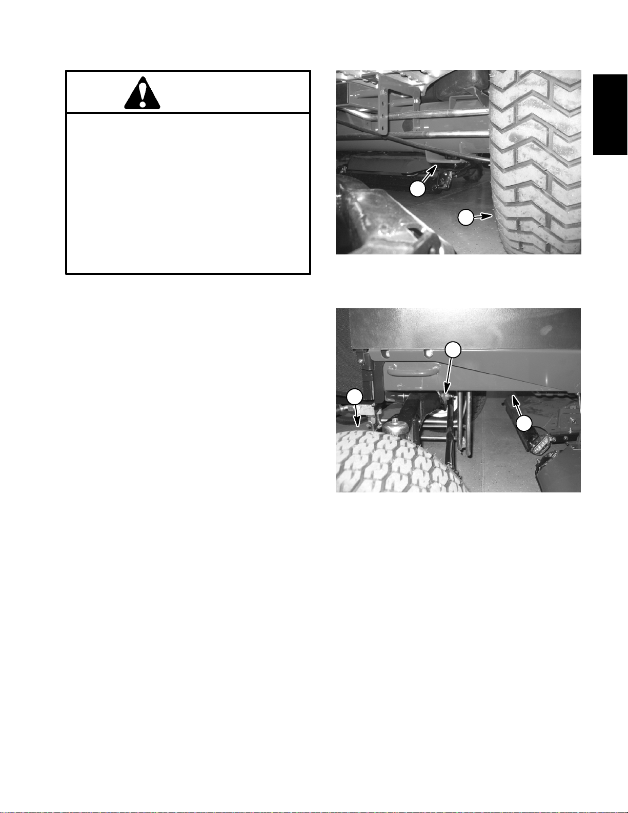
Front End Jacking
1. Applyparking brake and chockboth reartirestoprevent the machine from moving.
2. Position jack securely under the rectangular padon
the frame axle tube, just to the inside of the front wheel
(Fig. 1).
3. Jack front of machine off the ground.
4. Position jackstands under the frame as close to the
wheel as possible to support the machine.
Safety
2
1
Figure 1
1. Front wheel 2. Front jacking point
2
1
3
Rear End Jacking
1. Applyparkingbrakeandchockbothfront tires toprevent the machine from moving.
2. Place jacksecurelyat thecenter of the rear axleunder the axle pivot bracket. Jack rear of machine off the
ground.
3. Position jack stands under the frame to support the
machine.
1. Rear wheel
2. Rear axle pivot bracket
Figure 2
3. Jack stand location
Groundmaster 4300--D Page 1 -- 5 Safety
Page 10

Safety and Instruction Decals
Numerous safety and instruction decals are affixed to
the traction unit and cutting units of your Groundsmaster. If any decal becomes illegible or damaged, installa
new decal. Part numbers for decals are listed in your
Part Catalog. Order replacement decals from your Authorized Toro Distributor.
Groundsmaster 4300--DPage 1 -- 6Safety
Page 11

Product Records and Maintenance
Table of Contents
PRODUCT RECORDS 1.........................
MAINTENANCE 1...............................
EQUIVALENTS AND CONVERSIONS 2...........
Decimal and Millimeter Equivalents 2............
U.S. to Metric Conversions 2...................
TORQUE SPECIFICATIONS 3....................
Fastener Identification 3.......................
Using a Torque Wrench with an Offset Wrench 3..
Standard Torque for Dry, Zinc Plated and
Steel Fasteners (Inch Series) 4...............
Standard Torque for Dry, Zinc Plated and
Steel Fasteners (Metric Series) 5..............
Other Torque Specifications 6..................
Conversion Factors 6..........................
Chapter 2
Product Records
and Maintenance
Product Records
Insert Operator’s Manual and Parts Catalog for your
Groundsmaster at the end of this chapter. Additionally,
if any optional equipment or accessories have been
installedto your machine, insertthe Installation Instructions, Operator’s Manuals andParts Catalogsfor those
options at the end of this chapter.
Maintenance
Maintenanceprocedures andrecommendedservice intervals for your Groundsmaster areidentified in theOperator’s Manual. Refer to that publication when
performing regular equipment maintenance.
Groundsmaster 4300--D Page 2 -- 1 Product Records and Maintenance
Page 12
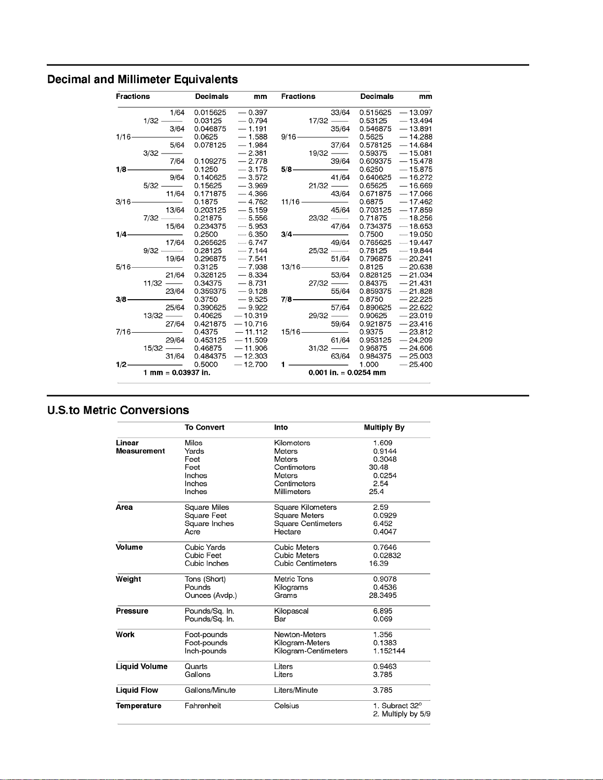
Equivalents and Conversions
0.09375
Groundsmaster 4300--DPage 2 -- 2Product Records and Maintenance
Page 13
Torque Specifications
Recommended fastener torque values are listed in the
followingtables.Forcriticalapplications,as determined
byToro,eitherthe recommended torque oratorque that
is unique to theapplication isclearly identifiedand specified in this Service Manual.
These Torque Specifications for the installation and
tightening of fasteners shallapply to allfasteners which
donot have a specific requirement identified inthis Service Manual. The following factors shall be considered
when applying torque: cleanliness of the fastener, use
of a thread sealant (e.g. Loctite), degree of lubrication
on the fastener, presence ofa prevailing torquefeature
(e.g. Nylock nut), hardness of the surface underneath
thefastener’sheadorsimilarcondition whichaffectsthe
installation.
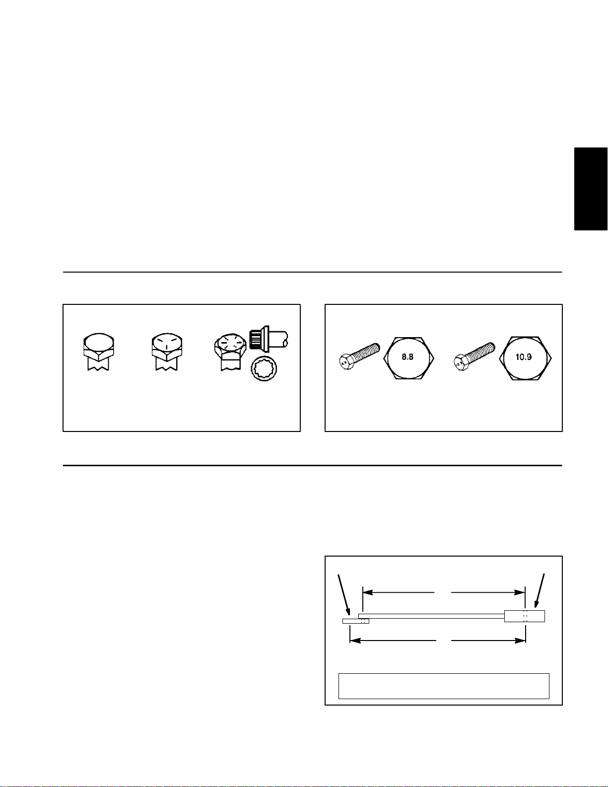
Fastener Identification
Asnoted inthe followingtables,torquevaluesshouldbe
reduced by 25% for lubricated fasteners to achieve
the similarstress as a dry fastener. Torque values may
also have to be reduced when the fastener is threaded
into aluminum or brass. The specific torque value
should be determined based onthe aluminum or brass
material strength, fastener size, length of thread engagement, etc.
The standard method of verifying torque shall be performed by marking a line on the fastener (head or nut)
and mating part, then back off fastener 1/4 of a turn.
Measurethe torque required to tighten the fasteneruntil
the lines match up.
Product Records
and Maintenance
Grade 1 Grade 5 Grade 8
Inch Series Bolts and Screws
Figure 1
Using a Torque Wrench with an Offset Wrench
Useofanoffsetwrench(e.g.crowfootwrench)willaffect
torquewrenchcalibration due to the effective change of
torquewrench length. When using atorquewrenchwith
an offset wrench, multiplythe listed torque recommendation by the calculated torque conversion factor (Fig.
3) to determine proper tightening torque. Tightening
torque when using a torque wrench with an offset
wrench will be lower than the listed torque recommendation.
Example: Themeasured effectivelength of the torque
wrench (distance from the center of the handle to the
center of the square drive) is 18”.
Themeasuredeffectivelengthofthetorquewrenchwith
the offset wrench installed (distance from the center of
the handle to the center of the offset wrench) is 19”.
Class 8.8 Class 10.9
Metric Bolts and Screws
Figure 2
If the listed torque recommendation for a fastener is
from 76 to 94 ft--lb, the proper torque when using this
torque wrench with an offset wrench would be from 72
to 89 ft--lb.
(effective length of
torque wrench)
A
B
(effective length of torque
wrench + offset wrench)
TORQUE CONVERSION FACTOR = A/ B
Torque wrenchOffset wrench
The calculated torque conversion factor for this torque
wrenchwiththisoffsetwrench would be 18 / 19 = 0.947.
Groundsmaster 4300--D Page 2 -- 3 Product Records and Maintenance
Figure 3
Page 14

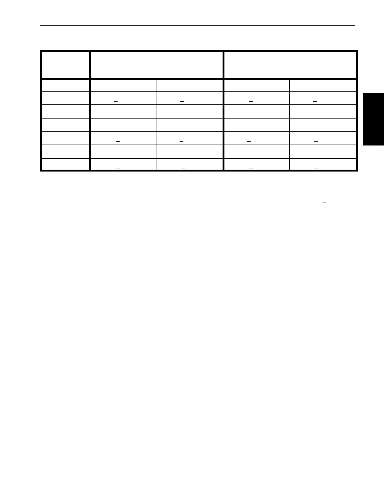
Standard Torque for Dry, Zinc Plated and Steel Fasteners (Inch Series)
Thread Size
# 6 -- 32 UNC
# 6 -- 40 UNF
# 8 -- 32 UNC
# 8 -- 36 UNF
#10--24UNC
#10--32UNF
1/4 -- 20 UNC 48 + 7 53 + 7 599 + 79 100 + 10 1130+ 113 140 + 15 1582 + 169
1/4 -- 28 UNF 53 +7 65 + 10 734 + 113 115 + 12 1299 + 136 160+ 17 1808 + 192
5/16 -- 18 UNC 115 + 15 105 +15 1186 + 169 200 + 25 2260 + 282 300 + 30 3390 + 339
5/16 -- 24 UNF 138 +17 128 + 17 1446 + 192 225 +25 2542 + 282 325 + 33 3672 +373
3/8 -- 16 UNC 16 + 2 16 + 2 22 + 3 30 + 3 41 + 4 43 + 5 58 + 7
Grade 1, 5 &
8withThin
Height Nuts
in--lb in--lb N--cm in--lb N--cm in--lb N--cm
10 + 2 13 + 2 147 + 23
13 + 2 25 + 5 282 + 30
18 + 2 30 + 5 339 + 56
ft--lb ft--lb N--m ft--lb N--m ft--lb N--m
SAE Grade 1 Bolts, Screws, Studs &
Sems with Regular Height Nuts
(SAE J995 Grade 2 or Stronger Nuts)
SAE Grade 5 Bolts, Screws, Studs &
Sems with Regular Height Nuts
(SAE J995 Grade 2 or Stronger Nuts)
15 + 2 169 + 23 23 + 3 262 + 34
17 + 2 192 + 23 25 + 3 282 + 34
29 + 3 328 + 34 41 + 5 463 + 56
31 + 4 350 + 45 43 + 5 486 + 56
42 + 5 475 + 56 60 + 6 678 + 68
48 + 5 542 + 56 68 + 7 768 + 79
SAE Grade 8 Bolts, Screws, Studs &
Sems with Regular Height Nuts
(SAE J995 Grade 5 or Stronger Nuts)
3/8 -- 24 UNF 17 +2 18 + 2 24 + 3 35 + 4 47 + 5 50 + 6 68 + 8
7/16 -- 14 UNC 27 + 3 27 + 3 37 + 4 50 + 5 68 + 7 70 + 7 95 + 9
7/16 -- 20 UNF 29 +3 29 + 3 39 + 4 55 + 6 75 + 8 77 + 8 104 + 11
1/2 -- 13 UNC 30 + 3 48 + 7 65 + 9 75 + 8 102 + 11 105 + 11 142+ 15
1/2 -- 20 UNF 32 +4 53 + 7 72 + 9 85 + 9 115 + 12 120 + 12 163 + 16
5/8 -- 11 UNC 65 + 10 88 + 12 119 + 16 150 + 15 203+ 20 210 + 21 285 + 28
5/8 -- 18 UNF 75 +10 95 + 15 129 + 20 170 + 18 230 + 24 240 + 24 325 + 33
3/4 -- 10 UNC 93 + 12 140 + 20 190 + 27 265 + 27 359 + 37 375 + 38 508 + 52
3/4 -- 16 UNF 115 + 15 165 + 25 224 + 34 300 +30 407 + 41 420 + 43 569 + 58
7/8 -- 9 UNC 140 + 20 225 + 25 305 + 34 430 + 45 583 + 61 600 + 60 813 + 81
7/8 -- 14 UNF 155 + 25 260 + 30 353 + 41 475 + 48 644 + 65 667 +66 904 + 89
NOTE: Reduce torque values listed inthe tableabove
by 25% for lubricated fasteners. Lubricated fasteners
are defined as threads coated with a lubricant such as
engine oil or thread sealant such as Loctite.
NOTE: The nominal torque values listed above for
Grade 5 and8 fasteners arebased on 75%of the minimumproofload specified in SAE J429. The toleranceis
approximately +
10% of the nominal torquevalue. Thin
height nuts include jam nuts.
NOTE: Torque values may have to be reduced when
installing fasteners into threaded aluminum or brass.
The specifictorque value should be determined based
on the fastener size, the aluminum or base material
strength, length of thread engagement, etc.
Groundsmaster 4300--DPage 2 -- 4Product Records and Maintenance
Page 15
Standard Torque for Dry, Zinc Plated and Steel Fasteners (Metric Series)
Class 8.8 Bolts, Screws and Studs with
Thread Size Regular Height Nuts
(Class 8 or Stronger Nuts)
Class 10.9 Bolts, Screws and Studs with
Regular Height Nuts
(Class 10 or Stronger Nuts)
M5 X 0.8 57 + 6in--lb 644 + 68 N--cm 78 + 8in--lb 881 + 90 N--cm
M6 X 1.0 96 + 10 in--lb 1085 + 113 N- -cm 133 +14 in--lb 1503 + 158 N--cm
M8 X 1.25 19 + 2ft--lb 26 + 3N--m 28 + 3ft--lb 38 + 4N--m
M10 X 1.5 38 + 4ft--lb 52 + 5N--m 54 + 6ft--lb 73 + 8N--m
M12 X 1.75 66 + 7ft--lb 90 + 10 N--m 93 + 10 ft--lb 126+ 14 N--m
M16 X 2.0 166+ 17 ft--lb 225 + 23 N--m 229 + 23 ft--lb 310 + 31 N--m
M20 X 2.5 325 + 33 ft--lb 440 + 45 N--m 450 + 46 ft--lb 610 + 62 N--m
NOTE: Reduce torque values listed inthe tableabove
by 25% for lubricated fasteners. Lubricated fasteners
are defined as threads coated with a lubricant such as
engine oil or thread sealant such as Loctite.
NOTE: The nominal torque values listed above are
based on 75% of the minimum proof load specified in
SAEJ1199.Thetoleranceisapproximately+
nominal torque value.
NOTE: Torque values may have to be reduced when
installing fasteners into threaded aluminum or brass.
The specifictorque value should be determined based
on the fastener size, the aluminum or base material
strength, length of thread engagement, etc.
10%ofthe
Product Records
and Maintenance
Groundsmaster 4300--D Page 2 -- 5 Product Records and Maintenance
Page 16
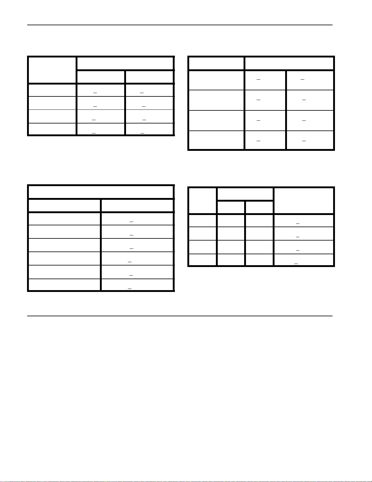
Other Torque Specifications
*
SAE Grade 8 Steel Set Screws
Recommended Torque
Thread Size
Square Head Hex Socket
1/4 -- 20 UNC 140 + 20 in--lb 73 + 12 in--lb
5/16 -- 18 UNC 215 + 35 in--lb 145 + 20 in--lb
3/8 -- 16 UNC 35 + 10 ft--lb 18 + 3ft--lb
1/2 -- 13 UNC 75 + 15 ft--lb 50 + 10 ft--lb
Thread Cutting Screws
(Zinc Plated Steel)
Type 1, Type 23 or Type F
Thread Size Baseline Torque*
No. 6 -- 32 UNC 20 + 5in--lb
Wheel Bolts and Lug Nuts
Thread Size
7/16 -- 20 UNF
Grade 5
1/2 -- 20 UNF
Grade 5
M12 X 1.25
Class 8.8
M12 X 1.5
Class 8.8
** For steel wheels and non--lubricated fasteners.
Thread Cutting Screws
(Zinc Plated Steel)
Thread
Size
No. 6 18 20 20 + 5in--lb
Threads per Inch
Type A Type B
Recommended Torque**
65 + 10 ft--lb 88 + 14 N--m
80 + 10 ft--lb 108 + 14 N--m
80 + 10 ft--lb 108 + 14 N--m
80 + 10 ft--lb 108 + 14 N--m
Baseline Torque
No. 8 -- 32 UNC 30 + 5in--lb
No. 10 -- 24 UNC 38 + 7in--lb
1/4 -- 20 UNC 85 + 15 in--lb
5/16 -- 18 UNC 110 + 20 in--lb
3/8 -- 16 UNC 200 + 100 in--lb
Conversion Factors
in--lb X 11.2985 = N--cm N--cm X 0.08851 = in--lb
ft--lb X 1.3558 = N--m N--m X 0.7376 = ft--lb
No. 8 15 18 30 + 5in--lb
No. 10 12 16 38 + 7in--lb
No. 12 11 14 85 + 15 in--lb
*Holesize,materialstrength,materialthicknessandfinish must be considered when determining specific
torquevalues. Alltorque values arebasedon non--lubricated fasteners.
Groundsmaster 4300--DPage 2 -- 6Product Records and Maintenance
Page 17

Table of Contents
Chapter 3
Kubota Diesel Engine
GENERAL INFORMATION 1.....................
Operator’s Manual 1..........................
Stopping the Engine 1.........................
SPECIFICATIONS 2............................
ADJUSTMENTS 3..............................
Adjust Throttle Control 3.......................
General Information
This Chapter gives information about specifications,
troubleshooting, testing andrepair of the Kubota diesel
engine used in the Groundsmaster 4300--D.
Most repairs and adjustments require tools which are
commonly available in many service shops. The useof
some specialized test equipment isexplained in theengine workshopmanual included at the endof thischapter. However, the cost of the test equipment and the
specialized natureof some repairs may dictate thatthe
work be done at an engine repair facility.
SERVICE AND REPAIRS 4......................
Fuel System 4................................
Air Cleaner 6.................................
Exhaust System 8............................
Radiator 10..................................
Engine 12....................................
KUBOTA WORKSHOP MANUAL, DIESEL ENGINE,
05--E3B SERIES
Service and repair parts for Kubota diesel engines are
suppliedthroughyour local T oroDistributor.If a parts list
is not available, be sure to provide your distributor with
the Toro model and serial number.
Engine
Kubota Diesel
Operator’s Manual
The Operator’s Manual provides information regarding
the operation, general maintenance and maintenance
intervals for the Kubota diesel engine that powers your
Groundsmaster machine. Refer to that publication for
additional information when servicing the machine.
Stopping the Engine
IMPORTANT: The engine used on the Ground smaster 4300--D isturbo--charged. Beforestopping
theengine aftermowing or full load operation,cool
the turbo-charger by allowing the engine to idle at
low speedfor five(5) minutes. Failure to do so may
lead to turbo-charger trouble.
Groundsmaster 4300--D Page 3 -- 1 Kubota Diesel Engine
Page 18

Specifications
Item Description
Make / Designation Kubota V1505--T--E3B, 4--stroke,
Number of Cylinders 4
Bore x Stroke 3.07 in x 3.09 in (78 mm x 78.4 mm)
Total Displacement 91.4 in3(1498 cc)
CompressionRatio 23:1
Firing Order 1 (fan end) -- 3 -- 4 (flywheel end) -- 2
Fuel No. 2--D Diesel Fuel (ASTM D975)
Fuel Injection Pump Bosch MD Type Mini
Fuel Injector Nozzle MiniNozzle (DNOPD)
Fuel Tank Capacity 14 U.S. gallons (53liters)
Governor Centrifugal Mechanical
Low Idle Speed(no load) 1250 to 1350 RPM
High Idle Speed (no load) 3050 to 3250 RPM
Liquid Cooled, OHV, Turbocharged Diesel
Engine Oil API Classification CI--4 or Higher
Oil Pump Gear Driven Trochoid Type
Crankcase Oil Capacity 5.5 U.S. quarts (5.2 liters) with Filter
Cooling System Capacity (including reserve tank) 10 U.S. quarts (9.5 liters)
Starter 12 VDC 1.2 KW
Alternator/Regulator 12 VDC 40 Amp
Engine Dry Weight (approximate) 251 lbs (114 kg)
(see Operator’s Manual for viscosity recommendations)
Groundsmaster 4300--DPage 3 -- 2Kubota Diesel Engine
Page 19
Adjustments
Adjust Throttle Control
Proper throttle operation is dependent upon proper adjustment of throttle control.
NOTE: The throttle cable swivel should be positioned
in the lowest hole in the speed control lever .
2
1. Move throttle control lever on control console to
FAST position.
2. Check position of the engine speed control lever on
fuel injection pump. The speed control lever should be
contacting the high speed screw whenthe throttlecontrol lever is in the FAST position.
3. If necessary,throttle controlcanbeadjustedbylooseningcable clampscrew andrepositioning control cable
until speed control lever contacts high speed screw
when the throttle control lever is in the FAST position.
Tighten cable clamp screw after adjustment has been
completed.
5
1
1. Throttle cable
2. High speed screw
3. Speed control lever
Figure 1
3
4
4. Swivel
5. Cable clamp
Engine
Kubota Diesel
Groundsmaster 4300--D Page 3 -- 3 Kubota Diesel Engine
Page 20
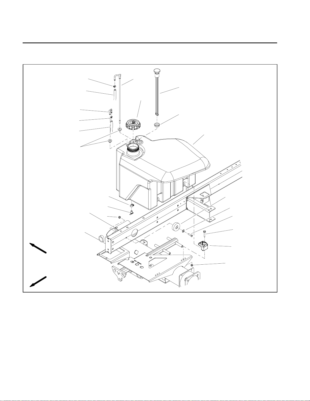
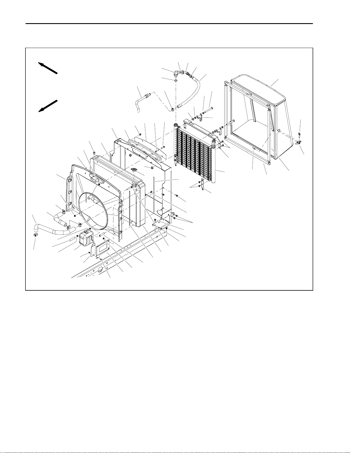
Service and Repairs
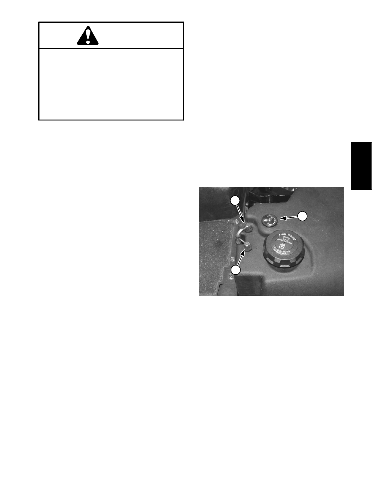
Fuel System
16
8
7
12
15
1
6
11
9
10
2
13
14
4
17
18
19
RIGHT
FRONT
1. Fuel cap
2. Bushing
3. Washer head screw (2 used)
4. Flange nut (3 used)
5. Clamp (2 used)
6. Returnfitting
7. Suction fitting
8. Hose clamp
9. Hose clamp
10. Fuel tank
11. Grommet
12. Fuel gauge
13. Hose clamp
3
5
4
Figure 2
14. Draincock
15. Fuel supply hose
16. Fuel return hose
17. Bumper
18. Flat washer
19. Cap screw
Groundsmaster 4300--DPage 3 -- 4Kubota Diesel Engine
Page 21
DANGER
Because diesel fuel is highly flammable, use
caution when storing or handling it. Do not
smoke while filling the fuel tank. Do not fill fuel
tankwhile engineis running, whenengineis hot
or when machine is in an enclosed area. Always
fill fuel tankoutsideand wipe up any spilled dieselfuelbefore startingtheengine. Store fuel in a
clean, safety--approved container and keepcontainer cap inplace.Use dieselfuel for theengine
only; not for any other purpose.
3. Opendraincockonbottomoffueltankandallow tank
to fully drain. Close draincock.
NOTE: Before removing fuel hoses from tank fittings,
label hoses for assembly purposes.
4. Loosenhose clampsanddisconnect fuel hoses from
suction (item 7) andreturn (item 6) fittings onthe top of
the fuel tank.
5. Remove fuel tank using Figure 2 as a guide.
Fuel Tank Installation (Fig. 2)
1. Install fuel tank to frame using Figure 2 as a guide.
Check Fuel Hoses and Connections
Check fuel hoses and connections periodically as recommended in theOperator’s Manual. Checkfuelhoses
for deterioration, damage, leakage or loose connections. Replace fuel hoses, clamps and connections as
necessary.
Drain and Clean Fuel Tank
Drain and clean the fuel tank periodically as recommendedinthe Operator’sManual. Also,drainandclean
the fuel tank if the fuel system becomes contaminated
or if the machineis tobestored foran extendedperiod.
To clean fuel tank, flush tank out with clean diesel fuel.
Make sure tank is free of all contaminates and debris.
Fuel Tank Removal (Fig. 2)
1. Park machine on a level surface, lower cutting
decks, stop engine, apply parking brake and remove
key from the ignition switch.
2. Placedrainpanunder fueltank. Make sure that drain
pan is large enough to hold fuel tank contents (see
Specifications in this chapter).
2. Using labels placed during fuel tank removal, correctly connect fuel hoses to suction (item 7) and return
(item 6) fittings on the top of the fuel tank. Secure fuel
hoses with hose clamps.
3. Make sure thatfuel tank draincock is closed.Fillfuel
tank.
1
3
2
Figure 3
1. Fuel supply hose
2. Fuel return hose
3. Fuel gauge
Engine
Kubota Diesel
Groundsmaster 4300--D Page 3 -- 5 Kubota Diesel Engine
Page 22

Air Cleaner
19
17
14
18
14
8
11
11
7
1
Thread
Sealant
11
6
4
3
16
5
2
12 to 15 in--lb
(1.4 to 1.6 N--m)
RIGHT
FRONT
1. Air cleaner assembly
2. Indicator
3. Adapter
4. Spring
5. Hex nut
6. Bolt
7. Hose
12
13
10
15
12
Figure 4
8. Hose
9. Mount bracket
10. Air cleaner stand
11. Hose clamp (3 used)
12. Flange nut (8used)
13. Cap screw (2 used)
14. Hose clamp (2 used)
12
12
VACUATOR
DIRECTION
9
20
15. Flange head screw (4 used)
16. Air cleaner mountingband
17. Spacer
18. Hose
19. Hose clamp
20. Flange head screw (2 used)
Groundsmaster 4300--DPage 3 -- 6Kubota Diesel Engine
Page 23
Removal (Fig. 4)
1. Park machine on a level surface, lower cutting
decks, stop engine, engage parking brake and remove
key from the ignition switch. Raise and support hood.
2. Remove air cleaner components as needed using
Figures 4 as a guide.
3. See Operator’s Manual for air cleaner service and
maintenance procedures.
Installation (Fig. 4)
IMPORTANT: Any leaks in the air filter system will
allowdirt into engineand will causeseriousengine
damage. Make sure that all air cleanercomponents
areingood conditionand areproperlysecured during assembly.
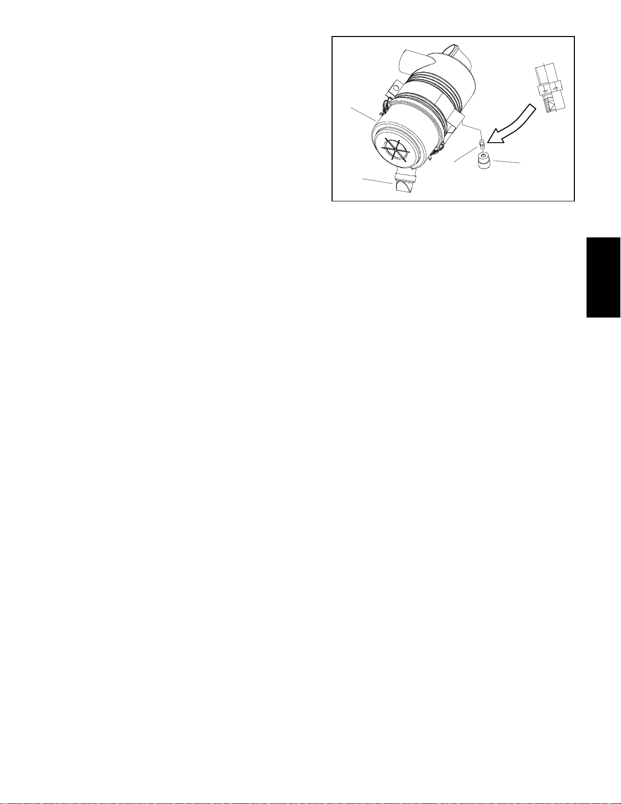
1. Assemble air cleaner system using Figure 4 as a
guide.
A. If service indicator (item 2) and adapter (item 3)
wereremovedfromaircleanerhousing,applythread
sealant to adapter threads before installing adapter
and indicator to housing. Install adapter so that
groovesinadapter hex andadapterfilter elementare
installed towardservice indicator (Fig.5).Torque indicator from 12 to 15 in--lb (1.4 to 1.6 N--m).
1
4
1. Air cleaner assembly
2. Service indicator
3
Figure 5
3. Adapter
4. Vacuator valve
2
Engine
Kubota Diesel
B. Makesurethatvacuator valve ispointeddownafter assembly.
Groundsmaster 4300--D Page 3 -- 7 Kubota Diesel Engine
Page 24
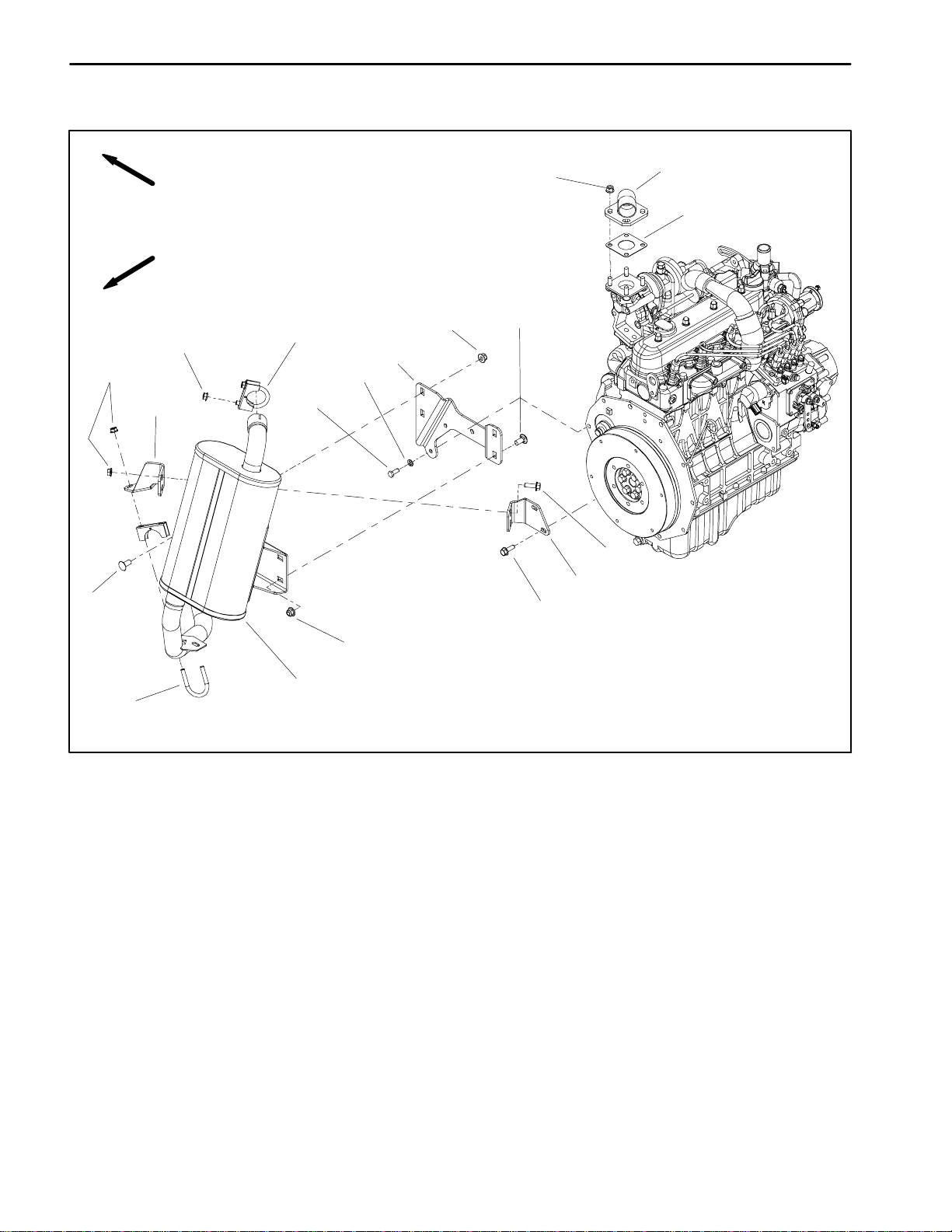
Exhaust System
3
RIGHT
13
1
FRONT
6
10
11
7
12
16
4
2
5
5
8
9
14
17
1. Gasket
2. Lock washer (2 used)
3. Flange nut (4 used)
4. Cap screw (2 used)
5. Carriage screw (4 used)
6. Flange nut (4 used)
6
15
7. Muffler support bracket
8. Flange head screw (2 used)
9. Tail pipe bracket
10. Hex nut (2 used)
11. Upper clamp
12. Flange nut (4used)
Figure 6
13. Exhaust header
14. Flange head screw (2 used)
15. Muffler
16. Tail pipe bracket
17. Lower clamp
Groundsmaster 4300--DPage 3 -- 8Kubota Diesel Engine
Page 25
Removal (Fig. 6)
1. Park machine on a level surface, lower cutting
decks, stop engine, engage parking brake and remove
key from the ignition switch. Raise and support hood.
CAUTION
The muffler and exhaust pipe may be hot. To
avoid possible burns, allow the engine and exhaust system to cool before working on the exhaust system.
2. Remove exhaust system using Figure 6 as a guide.
Installation (Fig. 6)
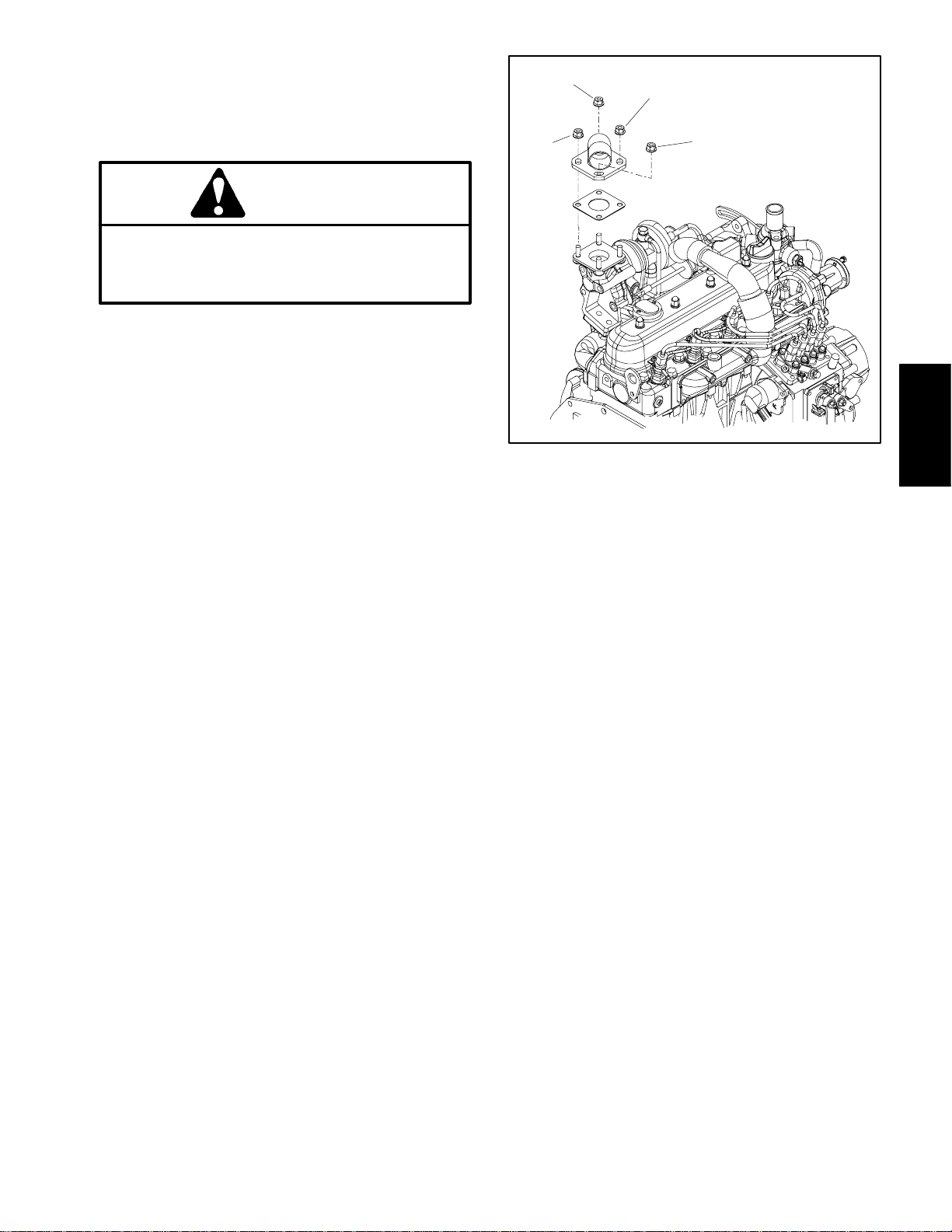
NOTE: Make sure mufflerflange and exhaustmanifold
sealing surfaces arefree of debris or damage that may
prevent a tight seal.
1. Place new muffler gasket on the exhaust manifold.
2. If muffler support bracket (item 7) was removed,secure it to engine with removed fasteners.
3
2
1 (FIRST)
4 (LAST)
Figure 7
Engine
Kubota Diesel
IMPORTANT: Fingertighten all exhaust systemfastenersbeforetightening so that there is no preload
on the exhaust system due to exhaust system assembly.
3. Installexhaust system components to the engineusing Figure 6as aguide. Finger tighten allfasteners until
all exhaust system components have been installed.
4. Tightenexhaust systemfastenersinthefollowingorder:
A. Lift muffler as much as holes in muffler support
bracket (item 7) will allow. Tighten flange nuts (item
6) to secure muffler to support bracket.
B. Tighten flange nuts (item 3) to secure exhaust
header (item 13)toengine flangeusing ordershown
in Figure 7.
C. Tighten hex nuts (item10) tosecureupper clamp
(item 11).
D. If tail pipe bracket(item 9) was removed, tighten
flange head screws (item 14) to secure bracket to
engine.
E. Tighten flange nuts (item 12) to secure lower
clamp (item 17).
F. Tighten fasteners (items 8 and 12) to secure tail
pipe brackets (items 9 and 16).
Groundsmaster 4300--D Page 3 -- 9 Kubota Diesel Engine
Page 26
Radiator
RIGHT
FRONT
27
9
41
40
45
35
16
16
28
36
19
20
20
12
22
8
5
15
42
44
43
37
18
46
13
5
12
47
5
17
39
7
29
31
4
11
13
10
26
25
10
2
10
3
2
1
34
23
1. Overflow bottle
2. Hose clamp (3 used)
3. Hose
4. Foam seal (2 used)
5. Foam seal (4 used)
6. Mounting bracket (2 used)
7. Oil cooler
8. Pipe plug
9. Hydraulic fitting (2 used)
10. Hose clamp (4 used)
11. Foam seal (2 used)
12. Flange nut (4used)
13. Flange nut (17used)
14. Oil cooler mount plate (2used)
15. Flange head screw (6 used)
16. Hose clamp (4 used)
33
6
2
21
5
38
13
24
Figure 8
17. Flange head screw (8 used)
18. Clamp (2 used)
19. Cap screw (2 used)
20. Washer (4 used)
21. Radiator
22. Radiator frame
23. Reservoir bracket
24. Reservoir bracket
25. Upper radiator hose
26. Lower radiator hose
27. Fan shroud
28. Hydraulic hose (2 used)
29. Rivet (2 used)
30. Flange head screw (10 used)
31. Draw latch
32. Washer head screw (6 used)
17
14
30
15
30
32
13
33. Flange head screw
34. Lock nut
35. O--ring
36. Screen
37. Intake screen
38. Hose
39. Oil cooler bracket
40. O--ring
41. Hydraulic tube
42. Foam seal
43. Spacer (5 used)
44. Flange head screw (5 used)
45. Hydraulic fitting (2 used)
46. Pin
47. Radiator cap
Groundsmaster 4300--DPage 3 -- 10Kubota Diesel Engine
Page 27
Removal (Fig. 8)
1. Park machine on a level surface, lower cutting
decks, stop engine, apply parking brake and remove
key from the ignition switch.
2. Raise and support the hood.
CAUTION
Do not open radiator cap or drain coolant if the
radiator or engine is hot. Pressurized, hot coolant can escape and cause burns.
10.Carefully pull radiator assembly from the machine.
Plug radiatorand hoseopenings toprevent contamination.
1 1.Inspect all foam seals placed between radiator , fan
shroud and radiator frame. Replace damaged foam
seals.
Installation (Fig. 8)
1. Remove plugs placedin radiatorand hose openings
during the removal procedure.
2. Carefully position radiator assembly to the radiator
support. Position fan shroud to the radiator.
Ethylene--glycol antifreeze is poisonous. Disposeof coolant properly, or storeitin aproperly
labeled container away from children and pets.
3. Drain coolant from radiator.
A. Slowly remove radiator cap from the radiator .
B. Place drain pan below the radiator draincock lo-
cated on the bottom of the radiator. Make sure that
drainpanislargeenough toholdcooling systemcontents (10 U.S. quarts (9.5 liters)).
C. Loosen radiator draincock (threaded in) and allow coolant to drain from radiator.
4. Remove screen from machine.
5. Disconnect radiator hoses (upper and lower) from
the radiator.
6. Loosen hose clampand removeoverflowhose from
radiator fill opening.
7. Remove two (2)flangehead screwsand flangenuts
that secure coolant reservoir and brackets to fan
shroud. Carefully position reservoir and brackets away
from the fan shroud.
8. Remove five (5)flange head screwsand flange nuts
that secure air intake screen (item 37) to machine. Remove screen and foam seal (item 42). Locate and retrieve five (5) spacers (item 43).
3. Securefanshroudandradiatortoradiatorframe with
removed flange head screws and flange nuts. Make
sure that atleast 0.250”(6.4mm)clearanceexistsat all
points between shroud opening and fan.
4. Position coolant reservoir and brackets to the fan
shroud. Secure reservoir to fan shroud and radiator
frame with two(2) flange head screws and flange nuts.
5. Place spacers (item43) into holes infoam seal(item
42). Position foam seal and air intake screen (item 37)
to radiator frame. Secure intakescreen tomachine with
five (5) flange head screws and flange nuts.
6. Connect upper and lower radiator hoses to radiator
and secure with clamps.
7. Connect overflow hose to radiator fill opening and
secure with hose clamp.
8. Makesureradiator draincockisclosed (threaded out
fully).
9. To allow air to escape during radiator filling, remove
pipe plug (item 8) from top of radiator. Fill radiator with
coolant. Make suretoinstallplugonceallairis bled from
radiator.
10.After radiator has been properly filled with coolant,
install radiator cap.
1 1.Lower and secure hood.
Engine
Kubota Diesel
9. Removeflange head screws and flange nuts thatsecure fanshroud andradiator to radiator frame. Position
fan shroud away from the radiator.
Groundsmaster 4300--D Page 3 -- 11 Kubota Diesel Engine
Page 28
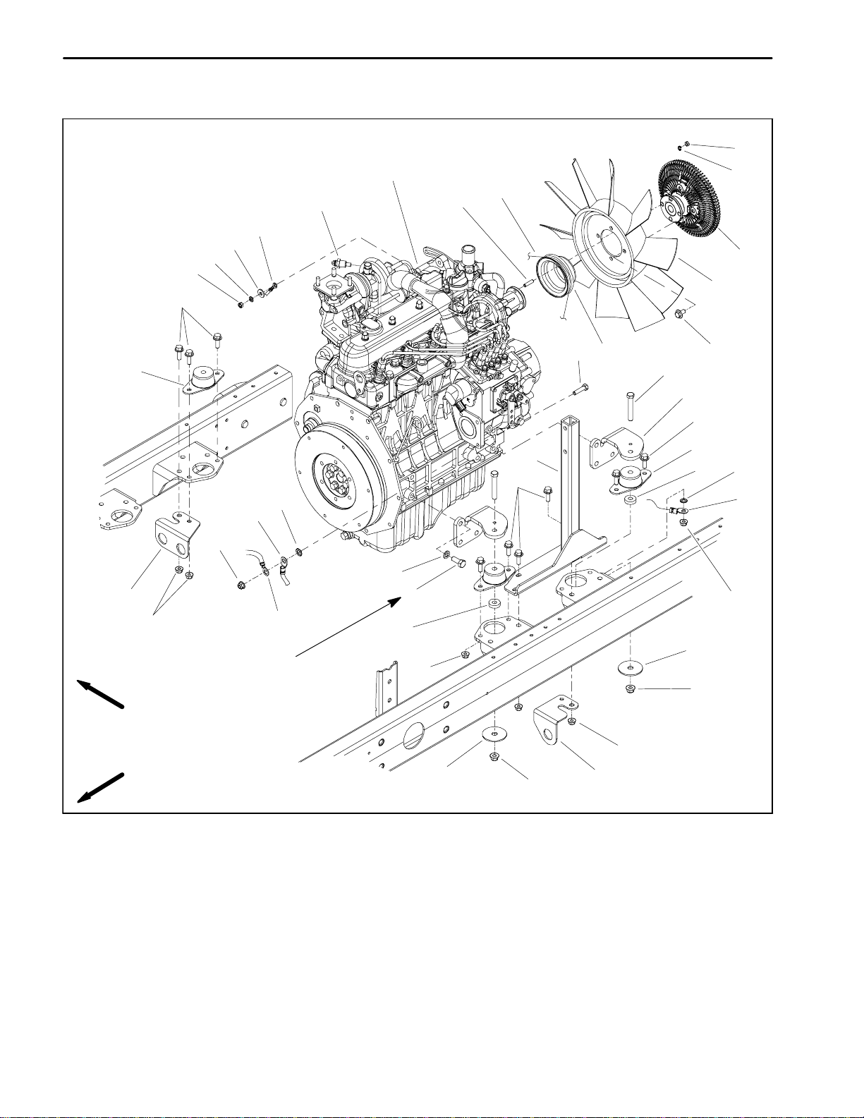
Engine
30
1
15
3
11
16
26
18
19
20
5
10
17
4
29
9
RIGHT
FRONT
13
23
9
32
34 to 42 ft--lb
(47to56N--m)
25
22
21
14
31
7
27
5
24
5
4
22
12
23
2
9
6
9
8
9
6
8
28
1. Engine assembly
2. Cap screw (12 used)
3. Temperature sender
4. Engine mount (4 used)
5. Flange head screw (13 used)
6. Snubbing washer (4 used)
7. Cap screw (4 used)
8. Flange nut (4 used)
9. Flange nut (14 used)
10. Fan clutch
11. Stud (4 used)
Figure 9
12. Lock washer
13. Lock washer
14. Pulley
15. V--belt
16. Lock washer (4 used)
17. Cooling fan
18. Flat washer
19. Spring washer
20. Hex nut
21. Cap screw
22. Spacer (4 used)
23. Negative battery cable
24. Air cleaner stand
25. Lock washer (12 used)
26. Fusible link harness
27. Engine mount (4used)
28. Bracket
29. Bracket
30. Hex nut
31. Flange head screw (4 used)
32. Wire harness ground
Groundsmaster 4300--DPage 3 -- 12Kubota Diesel Engine
Page 29
Removal (Fig. 9)
1. Park machine on a level surface, lower cutting
decks, stop engine and remove key from the ignition
switch. Chockwheelstokeepthemachinefrommoving.
2. Open and support hood.
3. Disconnect negative (--) cable and then positive (+)
cable from the battery.
CAUTION
2
1
3
Do not open radiator cap or drain coolant if the
radiator or engine is hot. Pressurized, hot coolant can escape and cause burns.
Ethylene--glycol antifreeze is poisonous. Disposeof coolant properly, or storeitin aproperly
labeled container away from children and pets.
4. Drain coolant from radiator (see Radiator Removal
in this section).
5. Remove air cleaner from machine (see Air Cleaner
Removal in this section).
6. Remove exhaust system from machine (see Exhaust System Removal in this section).
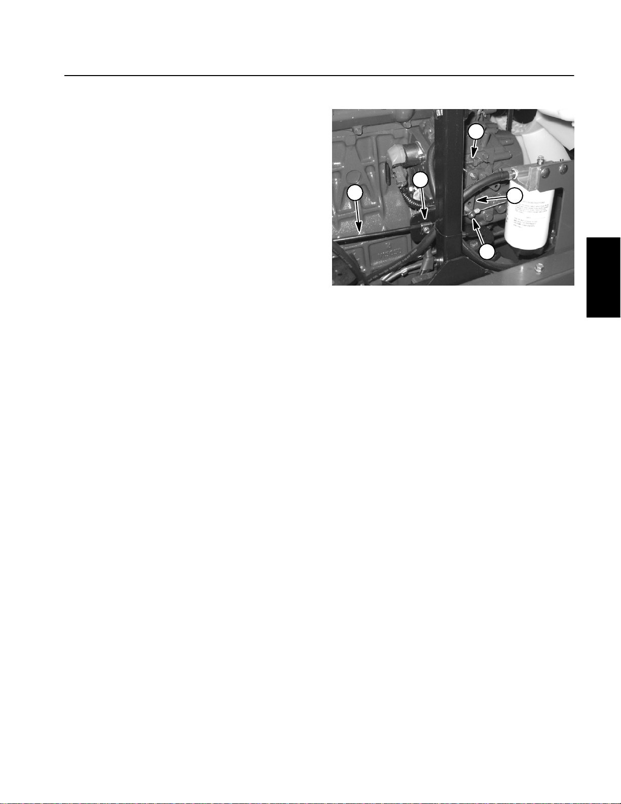
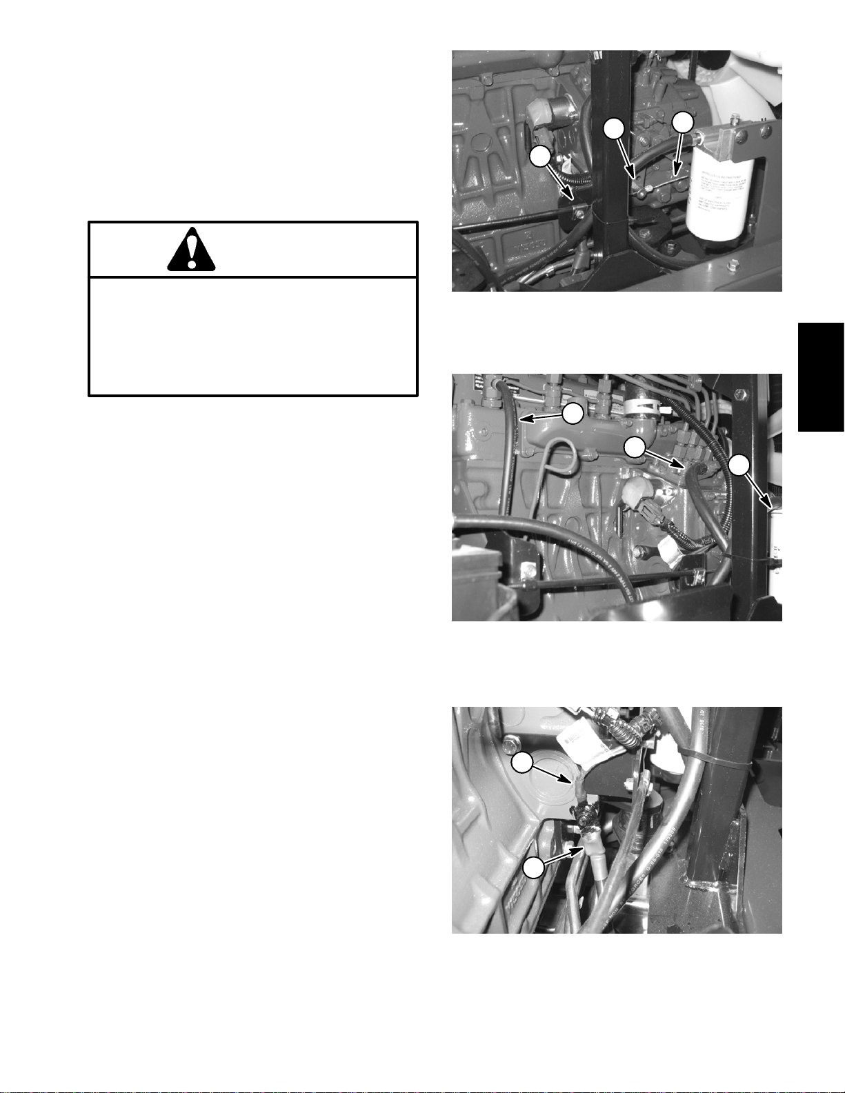
7. Remove throttle cable from injector pump (Fig. 10):
A. Remove cap screw that secures throttle cable
end to swivel in speed control lever.
B. Loosen throttle cable clamp and remove cable
from clamp. Slide throttle cable end from swivel.
C. Position throttle cable away from the engine.
1. Throttle cable end
2. Swivel
1. Fuel return hose
2. Fuel supply hose
Figure 10
1
Figure 11
3. Cable clamp
Engine
Kubota Diesel
2
3
3. Fuel/water filter
8. Disconnect hoses from engine:
A. Loosen clamps and remove upper and lower radiator hoses from the engine.
2
B. At injectorpump, loosenhose clamp anddisconnect supply fuel hose from the injector pump fitting
(Fig. 11).
C. Loosen hose clamp and disconnect fuel return
hose from front injector body (Fig. 11).
1
D. Plug disconnectedhoses andengineopeningsto
preventleakageand contamination.Positiondisconnected hoses away from engine.
1. Negative battery cable 2. Wire harness ground
Figure 12
Groundsmaster 4300--D Page 3 -- 13 Kubota Diesel Engine
Page 30
9. Disconnect hydraulic transmission drive shaft from
engine (see Hydraulic Transmission Drive Shaft Removal in the Service and Repairs section of Chapter 4
-- Hydraulic System). Support driveshaft away fromengine.
Installation (Fig. 9)
1. Locate machine on alevel surface with cuttingdecks
lowered and key removed from the ignition switch.
Chock wheels to keep the machine from moving.
10.Disconnectwireharness connectorsfrom thefollowing engine components:
NOTE: Before disconnectingwire harnessconnectors,
label all electrical leads for assembly purposes.
A. Alternator connector and stud.
B. Oilpressure switchlocatednear theengine oil fil-
ter.
C. Connector, fusible link connector and positive
battery cable from the starter motor.
D. High temperature shut down switch andtemper-
ature sender located on the water pump housing.
E. Fuel stop solenoid on injector pump.
F. Negative battery cable and wire harness ground
from injector pump (Fig. 12).
G. Glow plug strip.
1 1.Remove engine from machine:
2. Make sure that all parts removed from the engine
duringmaintenance or rebuilding are installedtothe engine.
3. If engine brackets were removed from the engine,
secure brackets to engine with lock washers and cap
screws. Torque cap screws from 34 to 42 ft--lb (47 to
56 N--m).
4. Install engine to machine.
A. Attach short sectionof chainbetween lift tabs lo-
cated on each end of the cylinder head
B. Connect a hoist or lift at the center of the short
section of chain. Apply enough tension on the short
chain so that the engine can be supported.
CAUTION
One person should operate hoist or lift while a
second person guides the engine into the machine.
A. Attach short sectionof chainbetween lift tabs located on each end of the cylinder head.
B. Connect a hoist or lift at the center of the short
section of chain. Apply enough tension on the short
chain so that the engine will be supported.
C. Remove fasteners that secure the engine (with
brackets) to the engine mounts.
CAUTION
One person should operate hoist or lift while a
secondpersonguides theengine out of themachine.
IMPORTANT: Make sure to not damage the engine, fuel hoses, hydraulic lines, electrical harness, radiator, battery or other parts while
removing the engine.
D. Raise engine and remove toward front of machine.
IMPORTANT: Make sure to not damage the engine, fuel hoses, hydraulic lines, electrical harness, radiator, battery or other parts while
installing the engine.
C. Lower engine to the machine frame. Make sure
fastener holes of the engine brackets are aligned
with the holes in the engine mounts.
D. Insert cap screw down through each engine
bracket and mount. Place spacer, snubbingwasher
and then flange nut on four (4) cap screws. Tighten
fasteners to secure engine to engine mounts.
5. Connect hydraulic transmissiondrive shaft toengine
(see Hydraulic Transmission Drive Shaft Installation in
the Serviceand Repairssectionof Chapter 4 -- Hydraulic System).
6. Connect all wire harness connectors to correct en-
gine components.
12.Ifnecessary, removeengine brackets(item27)from
engine.
Groundsmaster 4300--DPage 3 -- 14Kubota Diesel Engine
Page 31

7. Remove plugs installed in hoses during disassembly. Connect hoses to the engine:
9. Install aircleaner(see Air CleanerInstallationin this
section).
A. Connect fuel supply and fuel return hoses to engine fittings (Fig. 11). Secure with hose clamps.
B. Connect upper and lower radiator hoses to the
engine. Secure with hose clamps.
8. Connect throttle cable to injector pump (Fig. 10):
A. Route throttle cable to injector pump on engine.
B. Install the throttle cable end into the swivel in
speed control lever. Secure cable end with cap
screw.
C. Position cable under cable clamp.
D. Adjust throttle control (see Adjust Throttle Con-
trol in the Adjustments section of this chapter).
10.Install exhaust system to machine (see Exhaust
System Installation in this section).
1 1.Makesure radiator draincockisclosed (threaded out
fully). Fill radiator with coolant and install radiator cap
(see Radiator Installation in this section).
12.Check engine oil level and adjust if needed.
13.Connectpositive(+) batterycable tothebattery and
then connect negative (--) cable.
14.Bleed fuel system.
15.Close and secure hood.
Engine
Kubota Diesel
Groundsmaster 4300--D Page 3 -- 15 Kubota Diesel Engine
Page 32

This page is intentionally blank.
Groundsmaster 4300--DPage 3 -- 16Kubota Diesel Engine
Page 33

Table of Contents
Chapter 4
Hydraulic System
SPECIFICATIONS 2.............................
GENERAL INFORMATION 3.....................
Operator’s Manual 3..........................
Check Hydraulic Fluid 3.......................
Towing Machine 3.............................
Hydraulic Hoses 4............................
Hydraulic Hose and Tube Installation 5..........
Hydraulic Fitting Installation 6...................
Relieving Hydraulic System Pressure 8..........
Traction Circuit Component Failure 8............
HYDRAULIC SCHEMATIC 9.....................
HYDRAULIC FLOW DIAGRAMS 10...............
Traction Circuit 10.............................
Mow Circuit 12...............................
Mow Circuit Cutting Deck Blade Braking 14.......
Lift Circuit: Raise Cutting Decks 16..............
Lift Circuit: Lower Cutting Decks 18..............
Steering Circuit 20............................
SPECIAL TOOLS 22............................
TROUBLESHOOTING 26........................
General Hydraulic System Problems 26..........
Traction Circuit Problems 27....................
Mow Circuit Problems 28.......................
Lift Circuit Problems 29........................
Steering Circuit Problems 30...................
TESTING 32...................................
Traction Circuit Relief Valve (R3) and (R4)
Pressure Test 34............................
Traction Circuit Charge Pressure Test 36.........
Gear Pump (P3) Flow Test 38..................
Front Wheel Motor Efficiency Test 40............
Piston (Traction) Pump Flow Test 42.............
Relief Valve (PRV1) and (PRV2) Pressure Test 44.
Gear Pump (P1) and (P2) Flow Test 46..........
Deck Motor Efficiency Test 48..................
Lift Relief Valve (PRV) Pressure Test 50..........
Gear Pump (P4) Flow Test 52..................
Lift Cylinder Internal Leakage Test 54............
Steering Relief Valve (R10) Pressure Test 56.....
Steering Cylinder Internal Leakage Test 58.......
SERVICE AND REPAIRS 60.....................
General Precautions for Removing and Installing
Hydraulic System Components 60.............
Check Hydraulic Lines and Hoses 61............
Flush Hydraulic System 61.....................
Filtering Closed--Loop Traction Circuit 62.........
Hydraulic System Start--up 63..................
Hydraulic Reservoir 64........................
Hydraulic Pump Drive Shaft 66.................
Hydraulic Pump Assembly 68...................
Piston (Traction) Pump Service 72..............
Gear Pump Service 74
Wheel Motors 76........................
Front
Rear Wheel Motors 80.........................
Wheel Motor Service 84.......................
CrossTrax
CrossTrax
Deck Control Manifold 90......................
Deck Control Manifold Service 92...............
Cutting Deck Motor 94.........................
Cutting Deck Motor Service 96..................
Lift Control Manifold 100.......................
Lift Control Manifold Service 102................
Lift Cylinder 104..............................
Lift Cylinder Service 106.......................
Steering Control Valve 108.....................
Steering Control Valve Service 110..............
Steering Cylinder 112..........................
Steering Cylinder Service 114..................
Oil Cooler 116................................
SAUER--DANFOSS LPV CLOSED CIRCUIT AXIAL
PISTON PUMPS REPAIR MANUAL
SAUER--DANFOSS LPV CLOSED CIRCUIT AXIAL
PISTON PUMPS SERVICE INSTRUCTIONS
PARKER TORQMOTOR
(TC, TB, TE, TJ, TF, TG, TH AND TL SERIES)
SAUER--DANFOSS STEERING UNIT TYPE OSPM
SERVICE MANUAL
TM
AWD Manifold 86..................
TM
AWD Manifold Service 88...........
.........................
TM
SERVICE PROCEDURE
System
Hydraulic
Groundsmaster 4300--D Hydraulic SystemPage 4 -- 1
Page 34

Specifications
Item Description
Piston (Traction) Pump Sauer--Danfoss, LPV Closed Circuit Axial Piston Design
Maximum Pump Displacement (per revolution) 2.14 in
Gear Pump Casappa 4 section, positive displacement gear type pump
Section P1/P2 Displacement (per revolution) 1.03 in
Section P3 Displacement (per revolution) 0.37 in
Section P4 Displacement (per revolution) 0.24 in
Charge Circuit Relief (R5) Pressure 200 PSI (14 bar)
Traction Circuit Relief Pressure
Forward (R3) 3625 PSI (250 bar)
Reverse (R4) 3625PSI (250bar)
Front Wheel Motors Parker orbital rotor motor, TG Series
Displacement (per revolution) 24.7 in
Rear Wheel Motors Parker orbital rotor motor, TL Series
Displacement (per revolution) 18.9 in
Mow Circuit Relief Pressure
Rear Mow Circuit (PRV1) 2500 PSI (175 bar)
Front Mow Circuit (PRV2) 3500 PSI (241 bar)
Cutting Deck Motor Casappa gear motor
Displacement (per revolution) 1.05 in
Cross Over Relief Valve Pressure 1813 PSI (125 bar)
3
(35 cc)
3
(16.84 cc)
3
(6.1 cc)
3
(3.9 cc)
3
(405 cc)
3
(310 cc)
3
(17.16 cc)
Steering Valve Sauer--Danfoss Steering Unit, Type OSPMS
Displacement (per revolution) 6.1 in
Steering Circuit Relief (R10)Pressure 1000 PSI (70 bar)
Lift Circuit Relief (PRV)Pressure 2000 PSI (138 bar)
Hydraulic Filter (Charge and Steering Circuits) Spin--on Cartridge Type with 50 PSI (3.4 bar) Relief in Adapter
Hydraulic Filter (Mow and Lift Circuits) Spin--on Cartridge Type with 50 PSI (3.4 bar) Relief in Adapter
(filter adapter includes filter change indicator)
Hydraulic Oil See Operator’s Manual
Hydraulic Reservoir Capacity 14 U.S. Gallons (53 Liters)
3
(100 cc)
Groundsmaster 4300--DHydraulic System Page 4 -- 2
Page 35

General Information
Operator’s Manual
The Operator’s Manual provides information regarding
the operation, general maintenance and maintenance
intervals for your Groundsmaster 4300--D.Refer to that
publicationfor additionalinformationwhenservicing the
machine.
Check Hydraulic Fluid
The hydraulic system on your Groundsmaster is designedto operate on high qualityhydraulicfluid.Thehydraulic system reservoir holds approximately 14 U.S.
gallons (53 liters) of hydraulic fluid. Check level of hy-
draulicfluid daily.SeeOperator ’sManualfor fluidlevel
checking procedure and hydraulic oil recommendations.
1
Towing Machine
IMPORTANT: If towing limits are exceeded, severe
damage to the piston (traction) pump may occur.
Ifit becomes necessary totoworpush the machine, tow
orpushat a speed below 3 mph(4.8kph),andfora very
shortdistance. If themachineneedsto be moved a considerabledistance, machine should be transported on a
trailer.The piston (traction) pump isequipped with a bypassvalvethatneeds tobeloosenedfortowing orpushing (Fig. 2). Refer to Operator’s Manual for Towing
Procedures.
Figure 1
1. Hydraulic reservoir cap
2
System
Hydraulic
1
Groundsmaster 4300--D Hydraulic SystemPage 4 -- 3
Figure 2
1. Piston (traction) pump 2. Bypass valve
Page 36

Hydraulic Hoses
Hydraulichoses are subject to extreme conditions such
aspressuredifferentialsduring operation and exposure
to weather, sun, chemicals, very warm storage conditionsormishandlingduring operationandmaintenance.
These conditions can causehose damageand deterioration. Some hoses are more susceptible to these
conditions than others. Inspect all machine hydraulic
hoses frequently for signs of deterioration or damage:
WARNING
Beforedisconnectingor performing any work on
hydraulic system, relieve all pressure in system
(seeRelievingHydraulicSystemPressure in this
section).
Hard, cracked, cut, abraded, charred, leaking or
otherwise damaged hose.
Kinked, crushed, flattened or twisted hose.
Blistered, soft, degraded or loose hose cover.
Cracked, damaged or badly corroded hose fittings.
When replacing a hydraulichose, besure that thehose
is straight (not twisted) before tightening the fittings.
This can be done by observing the imprint (layline) on
the hose. Use two wrenches when tightening a hose;
hold the hose straight with one wrench and tighten the
hose swivelnut ontothe fittingwith thesecond wrench
(see Hydraulic Hose and Tube Installation in this section). If the hose has an elbow at one end, tighten the
swivel nut on that end before tightening the nut on the
straight end of the hose.
For additional hydraulic hose information, refer to Toro
Service Training Book, Hydraulic Hose Servicing (Part
Number 94813SL).
Keepbodyand handsawayfrompinhole leaksor
nozzles that eject hydraulic fluid under high
pressure. Use paper or cardboard, not hands, to
search for leaks. Hydraulic fluid escaping under
pressure can have sufficient force to penetrate
the skin and cause serious injury. If fluid is injected into the skin, it must be surgically removed within a few hours by a doctor familiar
withthis typeof injury.Gangrenemay resultfrom
such an injury.
Groundsmaster 4300--DHydraulic System Page 4 -- 4
Page 37

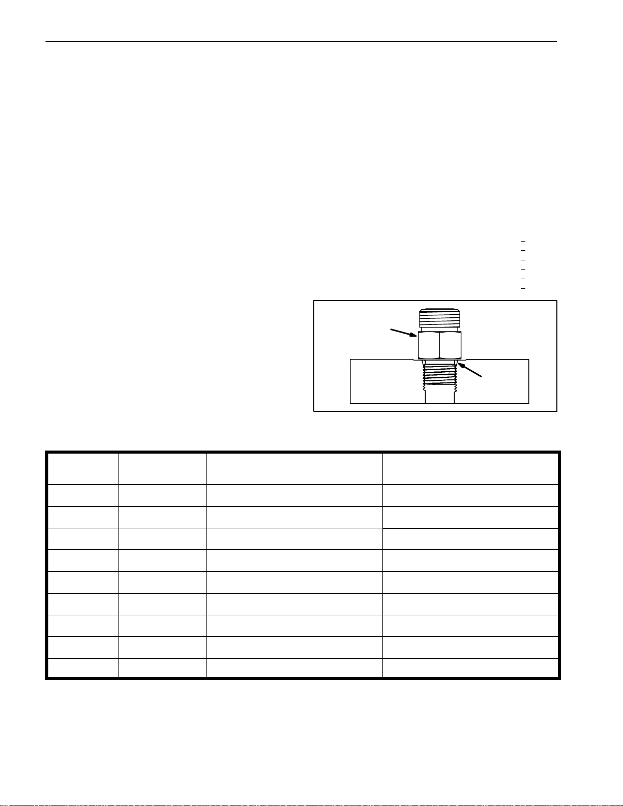
Hydraulic Hose and Tube Installation (O--Ring Face Seal Fitting)
1. Makesure threads and sealing surfacesofthehose/
tube and the fittingare freeof burrs,nicks, scratchesor
any foreign material.
2. Asa preventative measure against leakage,itisrecommended that the face seal O--ring be replaced any
time the connection isopened.Make sure theO--ring is
installedandproperly seatedinthefittinggroove.Lightly
lubricate the O--ring with clean hydraulic oil.
3. Place the hose/tube against the fitting body so that
theflatfaceofthehose/tubesleevefully contactsthe O-ring in the fitting.
4. Thread the swivel nutonto the fittingby hand.While
holding the hose/tube with a wrench, use a torque
wrench to tighten the swivel nut to the recommended
installation torque shown in Figure 5. This tightening
process will require the use of an offset wrench ( e.g.
crowfoot wrench). Use of an offset wrench will affect
torque wrench calibration due to the effective length
change of the torque wrench. Tightening torque when
usingatorquewrenchwithanoffsetwrenchwillbelower
than the listed installation torque (see Using a Torque
Wrench with anOffsetWrench in theTorque Specificationssectionof Chapter 2 -- Product Records andMaintenance).
C. Useasecond wrench totightenthe nuttothe correct FlatsFrom WrenchResistance (F.F.W.R.). The
markingsonthe nutandfittingbodywillverifythatthe
connection has been properly tightened.
Siz e F.F.W.R.
4 (1/4 in. nominal hose or tubing) 1/2 to 3/4
6 (3/8 in.) 1/2to 3/4
8 (1/2 in.) 1/2to 3/4
10 (5/8 in.) 1/2 to 3/4
12 (3/4 in.) 1/3 to 1/2
16 (1 in.) 1/3 to1/2
Swivel Nut
Tube or Hose
O--ring
Fitting Body
Figure 3
System
Hydraulic
5. If a torque wrench is not availableor if space at the
swivelnut prevents use ofatorquewrench, an alternate
method of assembly is the Flats From Wrench Resistance (F.F.W.R.) method (Fig. 4).
Mark Nut
and Fitting
Body
Final
Position
A. Usingawrench,tighten theswivelnut ontothefittinguntillightwrenchresistanceis reached(approxi-
Extend Line
mately 30 in--lb).
B. Mark the swivel nut and fitting body. Hold the
hose/tube with a wrench to prevent it from turning.
AT WRENCH RESISTANCE
Figure 4
Fitting Dash Size Hose/Tube Side Thread Size Installation Torque
4 9/16 -- 18 18to22ft--lb(25to29N--m)
6 11/16 - - 16 27to33ft--lb(37to44N--m)
8 13/16 -- 16 37to47ft--lb(51to63N--m)
10 1--14 60 to 74 ft--lb (82 to 100 N--m)
12 13/16--12 85 to 105 ft--lb (116 to 142 N--m)
Initial
Position
AFTER TIGHTENING
16 17/16--12 110 to 136 ft--lb (150 to 184 N--m)
20 1 11/16 -- 12 140 to 172 ft--lb (190 to 233 N--m)
Figure 5
Groundsmaster 4300--D Hydraulic SystemPage 4 -- 5
Page 38
Hydraulic Fitting Installation (SAE Straight Thread O--Ring Fitting into Component Port)
Non--Adjustable Fitting (Fig. 6)
1. Make sure allthreads and sealingsurfaces offitting
and component port are free of burrs, nicks, scratches
or any foreign material.
2. Asa preventative measure against leakage,itisrecommended that the O--ring be replaced any time the
connection is opened.
3. Lightly lubricate the O--ring with clean hydraulic oil.
Fittingthreadsshouldbecleanwithnolubricantapplied.
IMPORTANT: Before installing fitting into port, determine port material.If fittingis to beinstalled into
an aluminum port, installation torque is reduced.
4. Install the fitting into the port. Then, use a torque
wrench and socket to tighten the fitting to the recommended installation torque shown in Figure 7.
NOTE: Useof an offsetwrench (e.g.crowfoot wrench)
will affect torquewrench calibration due tothe effective
length change of the torque wrench. Tightening torque
when using a torque wrench with an offset wrench will
be less than the recommendedinstallation torque. See
Using a Torque Wrench with an Offset Wrench in the
Torque Specifications section of Chapter 2 -- Product
Recordsand Maintenancetodetermine necessaryconversion information.
5. If a torquewrench is not available, or if spaceat the
portpreventsuseof atorque wrench,analternate method ofassembly is the Flats From Finger Tight (F.F.F.T.)
method.
A. Install thefitting into the port and tighten it down
full length until finger tight.
B. If port material is steel, tighten the fitting to the
listed F.F.F .T. Ifport material is aluminum,tighten fitting to 60% of listed F.F.F.T.
Siz e F.F.F.T.
4 (1/4 in. nominal hose or tubing) 1.00 +
6(3/8in.) 1.50+
8(1/2in.) 1.50+
10 (5/8 in.) 1.50 +
12 (3/4 in.) 1.50 +
16 (1 in.) 1.50 +
Fitting
O--ring
0.25
0.25
0.25
0.25
0.25
0.25
Figure 6
Fitting
Dash Size
Fitting Port Side
Thread Size
Installation Torque Into
Steel Port
Installation Torque Into
Aluminum Port
4 7/16 -- 20 15to19ft--lb(21to25N--m) 9to11ft--lb(13to15N--m)
5 1/2 -- 20 18to22ft--lb(25to29N--m) 11to15ft--lb(15to20N--m)
6 9/16 -- 18 34to42ft--lb(47to56N--m) 20to26ft--lb(28to35N--m)
8 3/4 -- 16 58to72ft--lb(79to97N--m) 35to43ft--lb(48to58N--m)
10 7/8 -- 14 99 to 121 ft--lb (135 to 164 N--m) 60 to 74 ft--lb (82 to 100 N--m)
12 11/16--12 134 to 164 ft--lb (182 to 222 N--m) 81 to 99 ft--lb (110 to 134 N--m)
14 13/16--12 160 to 196 ft--lb (217 to 265 N--m) 96 to 118 ft--lb (131 to 160 N--m)
16 15/16--12 202 to 248 ft--lb (274 to 336 N--m) 121 to 149 ft--lb (165 to 202 N--m)
20 15/8--12 247 to 303 ft--lb (335 to 410 N--m) 149 to 183 ft--lb (202 to 248 N--m)
Figure 7
Groundsmaster 4300--DHydraulic System Page 4 -- 6
Page 39

Adjustable Fitting (Fig. 8)
1. Make sure allthreads and sealingsurfaces offitting
and component port are free of burrs, nicks, scratches
or any foreign material.
2. Asa preventative measure against leakage,itisrecommended that the O--ring be replaced any time the
connection is opened.
3. Lightly lubricate the O--ring with clean hydraulic oil.
Fittingthreadsshouldbecleanwithnolubricantapplied.
4. Turnback thelock nut asfar aspossible. Makesure
the back up washeris notloose and ispushed up asfar
as possible (Step 1 in Figure 9).
IMPORTANT: Before installing fitting into port, determine port material.If fittingis to beinstalled into
an aluminum port, installation torque is reduced.
Lock Nut
Back--up Washer
O--ring
Figure 8
5. Install the fitting intothe port and tighten finger tight
until the washer contactsthe faceof theport ( Step 2 in
Figure 9). Make sure that the fitting does not bottomin
the port during installation.
6. Toput the fitting in thedesiredposition,unscrew it by
the required amount to align fitting with incoming hose
or tube, butno more than one fullturn (Step 3 inFigure
9).
7. Hold the fittingin thedesired position with a wrench
and use a torque wrench to tighten the lock nut to the
recommended installation torque shown in Figure 7.
This tighteningprocess willrequire theuse of an offset
wrench (e.g. crowfoot wrench). Useof an offset wrench
will affect torquewrench calibration due tothe effective
length change of the torque wrench. Tightening torque
when using a torque wrench with an offset wrench will
be lower thanthe listed installation torque (seeUsing a
Torque Wrench with an Offset Wrench in the Torque
Specifications section of Chapter 2 -- Product Records
and Maintenance).
8. If a torquewrench is not available, or if spaceat the
portpreventsuseof atorque wrench,analternate method ofassembly is the Flats From Finger Tight (F.F.F.T.)
method. Hold the fitting in the desired position with a
wrench and, ifport materialis steel, tightenthe lock nut
witha second wrench to the listedF.F.F.T (Step 4 in Figure9).Ifportmaterialis aluminum, tighten fitting to 60%
of listed F.F.F.T.
Step 3Step 1
Step 2 Step 4
Figure 9
System
Hydraulic
Siz e F.F.F.T.
4 (1/4 in. nominal hose or tubing) 1.00 +
6(3/8in.) 1.50+
8(1/2in.) 1.50+
10 (5/8 in.) 1.50 +
12 (3/4 in.) 1.50 +
16 (1 in.) 1.50 +
0.25
0.25
0.25
0.25
0.25
0.25
Groundsmaster 4300--D Hydraulic SystemPage 4 -- 7
Page 40

Relieving Hydraulic System Pressure
Beforedisconnectingorperforming any work on the hydraulic system, all pressure in the hydraulic system
mustberelieved.Parkmachineonalevel surface,lower
cutting decks fully, stop engine and engage parking
brake.
To relieve hydraulic pressure in traction circuit, move
tractionpedal to both forward and reversedirections.To
relieve hydraulic pressure in steering circuit, rotate
steering wheel in both directions.
System pressure in cutting circuit is relieved when the
cutting decks are disengaged.
Traction Circuit Component Failure
The traction circuit on Groundsmaster 4300--D machines is a closed loop system that includes the piston
(traction) pump and four (4) wheel motors. Ifa componentinthetractioncircuitshouldfail,debrisandcontamination from the failed component will circulate
throughout the traction circuit. This contamination can
damageother components inthecircuit so itmustbe removed to prevent additional component failure.
The recommended method of removing traction circuit
contamination would be to temporarily install the high
flow hydraulic filter (see Special Tools in this chapter)
intothe circuit. This filter should be used whenconnecting hydraulic test gauges in order to test tractioncircuit
components or after replacing a failed traction circuit
component(e.g. traction(piston)pump or wheelmotor).
The filter will ensure that contaminates are removed
from the closed loop and thus, do notcause additional
component damage.
Once the Toro high flow hydraulic filter kit has been
placedin the circuit, raise and support the machinewith
all wheels off the ground.Then, operate thetraction cir-
To relieve hydraulic pressure in lift circuit, turn ignition
switchtoON(do notstartengine) andfullylower thecutting decks. After decks are fully lowered, turn ignition
switch to OFF and remove key from the switch.
IMPORTANT: If machinewill be serviced on a lift or
atan elevated position,fullylower the cuttingdecks
afterthemachine hasbeenraised to ensure that the
lift cylinders are fully extended. Pressure will be
maintained in the lift cylinders unless they arefully
extended.
cuit to allow oil flowthroughout the circuit. The filterwill
remove contamination from the traction circuit during
operation. Because the Toro high flow filter is bi--directional,the tractioncircuitcan beoperatedin both theforward and reverse direction. The filter should be
removed from the machine after contamination has
been removed from the traction circuit. See Filtering
Closed--LoopTractionCircuitintheServiceandRepairs
section of this chapter for additional information on using the Toro high flow hydraulic filter.
Thealternative tousing theTorohigh flowhydraulicfilter
kit after a traction circuit component failure would beto
disassemble, drain and thoroughly clean all components, tubes and hoses in the tractioncircuit. If any debris remains in the traction circuit and the machine is
operated,thedebriscancauseadditionalcircuit component failure.
NOTE: The traction pump case drain could allow any
debrisinthe tractioncircuittocontaminateother hydraulic circuits on the machine.
Groundsmaster 4300--DHydraulic System Page 4 -- 8
Page 41

Hydraulic Schematic
CYLINDER
STEERING
VALVE
CONTROL
STEERING
LIFT
CONTROL
MANIFOLD
Hydraulic Schematic
Groundsmaster 4300--D
de--energized
All solenoids are shown as
System
Hydraulic
MANIFOLD
CROSSTRAX
VALVE
BYPASS
GEAR
PUMP
PUMP
PISTON
(TRACTION)
Groundsmaster 4300--D Hydraulic SystemPage 4 -- 9
DECK
CONTROL
MANIFOLD
NOTE: A larger hydraulic schematic is
included in Chapter 8 -- Foldout Drawings
Page 42

Hydraulic Flow Diagrams
VALVE
CONTROL
STEERING
CYLINDER
STEERING
LIFT
CONTROL
MANIFOLD
Working Pressure
Low Pressure (Charge)
Return or Suction
Flow
Traction Circuit (Forward Shown)
Groundsmaster 4300--D
GEAR
PUMP
BYPASS
MANIFOLD
CROSSTRAX
VALVE
DECK
CONTROL
MANIFOLD
PUMP
PISTON
(TRACTION)
Figure 10
Groundsmaster 4300--DHydraulic System Page 4 -- 10
Page 43

Traction Circuit
The hydraulic traction circuit consists of a variable displacementpistonpump(P5)connectedinaclosedloop,
parallel circuit to four (4) orbital roller vane wheel motors. The traction pump input shaft is rotated by a drive
shaft that is driven from the engine flywheel.
Forward traction circuitpressure can bemeasured at a
test port located in thehydraulic tube that connects the
front wheel motors. Reverse traction circuit pressure
can be measuredat test portsin the AWD control manifold.
Forward Direction (Fig. 10)
Pushing the top ofthe tractionpedal anglesthe traction
pump swash plate to create a flow of oil.This oil flow is
directed to the wheel motors via hydraulic hoses and
tubes to drivethe wheels inthe forward direction.Traction pump flow isdirected tothe frontwheel motorsand
thentotheopposite rearwheelmotors tomaximizetraction. To reduce tire scuffing when turning, traction system pressureis equalized in the AWD control manifold
with an orifice and a bi--directional relief valve. Check
valvesintheAWDmanifold allow the rear wheel motors
toover--runduringtight turns.Forward tractionpressure
is limited to 3625 PSI (250 bar) by the forward traction
relief valve (R3) located in the traction pump.
Oilflowingfromthe w heel motors returns to the variable
displacement pump and is continuously pumped
through the tractioncircuit as long as thetraction pedal
is pushed.
Theangle of the swash platedeterminespumpflowand
ultimatelytractionspeed.Whenthetractionpedalisdepressedasmallamount,asmallswashplaterotationresultsinlowpumpoutputandlowertractionspeed.When
the traction pedal is depressed fully, the pump swash
platerotatesfullytoprovidemaximumpumpoutputand
traction speed.
Gearpump section (P3)suppliesoilflow for thesteering
circuitand also provides aconstant supply ofcharge oil
to the closed loop traction circuit. This charge oil provideslubricationfortractioncircuitcomponentsandalso
replenishes traction circuit oil thatis lost due to internal
leakage in the traction circuit.
Gear pump section (P3) takes its suction from the hydraulicreservoir.Chargepumpflowisdirectedtothelow
pressure side of theclosed looptraction circuit. Charge
relief valve (R5) located in the traction pump limits the
charge relief pressure to 200 PSI (14 bar).
The piston pump is equippedwith a casedrain toallow
internal leakage to be removed from the pump. The
case drain is connected to the gear pump inlet.
The piston pump (P5) includes a flushing valve that
bleeds off a small amount of hydraulic fluid for cooling
ofthe closedlooptraction circuit.Thechargesystem replenishes oil that is bled from the traction circuit by the
flushing valve.
Reverse Direction
The traction circuitoperates essentially the same inreverse as it does in the forward direction. However, the
flow through thecircuit isreversed. Pushing the bottom
of the traction pedal rotates the traction pump swash
plate to create a flow of oil. This oil is directed to the
wheel motors to drive the wheels in the reverse direction. Reverse traction pressure is limited to 3625 PSI
(250bar)bythereversetractionr elief valve(R4) located
in the traction pump.
Oil flowing from the wheelmotors returnsto thetraction
pump and is continuously pumped through the closed
loop traction circuit as long as the traction pedal is
pushed.
The charge circuit andflushing valvefunction thesame
in reverse as they do in the forwarddirection.
System
Hydraulic
Groundsmaster 4300--D Hydraulic SystemPage 4 -- 11
Page 44

VALVE
CONTROL
STEERING
CYLINDER
STEERING
LIFT
CONTROL
MANIFOLD
Groundsmaster 4300--D
Working Pressure
Mow Circuit
Low Pressure (Charge)
Return or Suction
Flow
GEAR
PUMP
BYPASS
MANIFOLD
CROSSTRAX
VALVE
DECK
CONTROL
MANIFOLD
PUMP
PISTON
(TRACTION)
Figure 11
Groundsmaster 4300--DHydraulic System Page 4 -- 12
Page 45
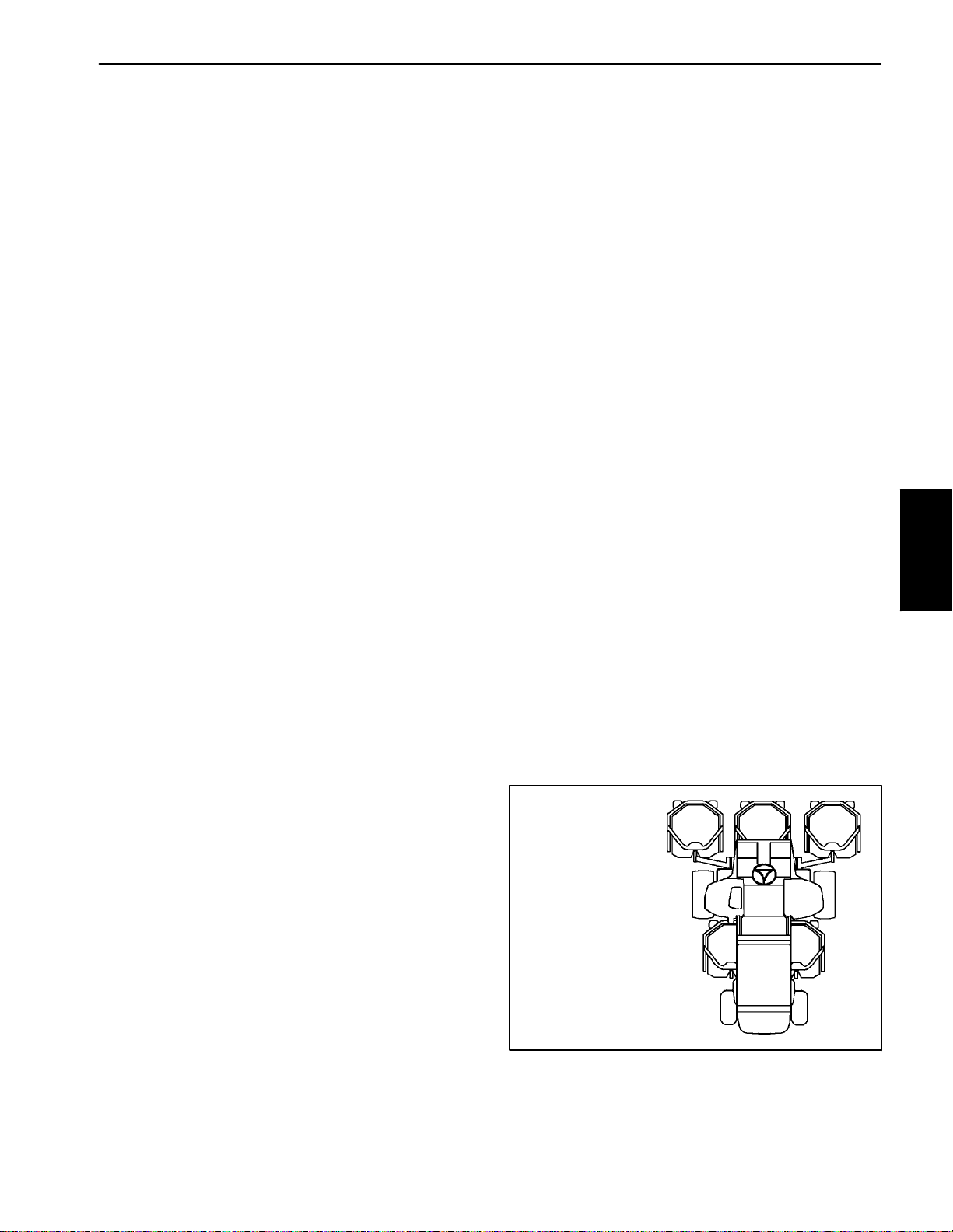
Mow Circuit
A four sectiongear pump is coupled tothe piston(traction) pump. Gear pump sections (P1) and (P2) supply
hydraulic flow for the mow circuit. These gear pumps
take their suction from the hydraulic reservoir.
Thedeck control manifold contains two (2) independent
controlcircuits for the front and rear cuttingdecks.Each
circuit is supplied by its own pump section. Pump section (P1) supplies hydraulic power to the rear cutting
decks with circuit control by proportional relief valve
(PRV1), relief valve (RV1) and logic cartridge (LC1) in
the deck control manifold. Pump section (P2) supplies
thefrontcutting deckswithcircuitcontrolbyproportional
reliefvalve(PRV2),reliefvalve(RV2)andlogiccartridge
(LC2) in the deck control manifold. Both circuits share
manifoldportT,whichdrainstothe oilcooler,oilfilterand
hydraulic reservoir.
Cutting deck motorsare equipped witha cross over relief valve to prevent hydraulic component damage in
case a single cutting deck should stall.
The machine controller uses inputs from various machineswitchestodeterminewhenthe solenoids for proportional relief valves (PRV1) and (PRV2) are to be
energized. The controller alsoprovides aslight delayin
activation of rear cutting decks.
PTO Not Engaged
Whenproportionalreliefvalves (PRV1) and (PRV2) are
notenergized (PTOswitchin theOFFpositionor cutting
decksraised), flow from pump sections (P1)and (P2) is
directedthroughtheunshifted proportionalreliefvalves,
out the mowcontrol manifold portT and then returns to
thehydraulicreservoir throughtheoilfilterandoilcooler,
bypassing the deck motors. The manifold logic cartridges (LC1 and LC2) remain in the unshifted position
to prevent any return flow from the deck motors so the
motors will not rotate.
amanifold sensingline.This flowpassesthrough anorificewhichcausesapressuredifferentialthat shifts logic
cartridge LC1. The shifted LC1allows circuit flow to rotate the rear cutting deck motors. Return oil from the
deck motors is directed through the shifted logic cartridge(LC1),manifoldportT,oilcooler,oil filter and then
to the reservoir. Deck motorcase drainleakage returns
directly to the hydraulic reservoir.
Mow circuit pressure for the rear cutting decks (pump
section P1) can be measured at deck control manifold
port G1.
The frontcutting deck circuit operates the same as the
rear cutting deck circuit. Deck control manifold proportional relief (PRV2), relief valve (RV2) and logic cartridge (LC2) are used to control the front cutting deck
circuit. Mow circuit pressure for the front cutting decks
(pump section P2) can be measured at deck control
manifold port G2.
Cutting Deck Circuit Relief
Maximum cutting deck circuit pressure is limitedby the
proportional relief valves in the hydraulic control manifold. Thefront deck circuit valve (PRV2) is set at 3500
PSI (241bar) and the rear deck circuit valve (PRV1) is
set at 2500 PSI (175 bar).
When increased circuitresistance is met(e.g. a cutting
blade should strike an object),the pressure increase is
felt at the proportional relief valve. If circuit pressure
shouldexceed thereliefsetting, thevalvewillopen toallow circuit flow toreturn to tank throughmanifold portT.
When circuit pressure lowers, thevalve closes toallow
flow to return to the deck motors.
#4 #1 #5
System
Hydraulic
PTO Engaged (Fig. 11)
When proportional relief valve (PRV1) is energized by
thecontroller (PTOswitchin the ONpositionand cutting
decks lowered), the proportional relief valve shifts and
prevents pump section (P1) flow through the valve.
Pump flow that entereddeck controlmanifold port P1is
then directed toward the rear cutting deck motors. Because logic cartridge LC1 is unshifted, circuit pressure
increases until manifoldrelief valve(RV1) isopened by
a manifold pilot piston. The shiftedrelief valve allows a
small amount ofhydraulic flow to return totank through
Groundsmaster 4300--D Hydraulic SystemPage 4 -- 13
GROUNDSMASTER
4300--D CUTTING
DECK LOCATIONS
#3#2
Figure 12
Page 46

Mow Circuit Cutting Deck Blade Braking
When the operator turns the PTO switch OFF or if the
decksareraisedwiththePTOswitch ON, the deck control manifold proportional relief valves (PRV1 and
PRV2) are de-- energized causing circuit flowto bypass
thedeck motors and return to the reservoirout manifold
portT(refertoinformationin MowCircuitinthissection).
Without circuit flow, the manifold relief valve (RV1 or
RV2)returnstoitsneutralpositionwhichcausesthelogic cartridge (LC1 or LC2) to shift to its neutral position,
blocking return flow from the deck motors and slowing
the cutting blades (Fig. 13).
Theinertiaoftherotatingcutting blades,however,effectively turns the deck motors into pumps causing an increaseinpressure as the flow from themotor comes up
against the closed logic cartridge (LC1 or LC2). When
this pressure builds to approximately 1500 PSI (105
bar), the relief valve (RV1 or RV2) re--opens which allows a small amount of hydraulic flow to return to tank
through a manifold sensing line (Fig. 14). This flow
causes a pressure differential that shifts the logic cartridge(LC1 or LC2) toonce again allowoil flow fromthe
motors (Fig. 15). When return pressure drops below
1500 PSI (105 bar), the relief valve (RV1 or RV2) reseats and causes the logic cartridge (LC1 or LC2) to
close again, blocking return flow from the deck motors
tofurther slow thecuttingblades. Thisactionof therelief
valve opening and the logic cartridge shifting occurs
severaltimesina very short time frame as theblades finallycome to astop.Once the bladeshavestopped,the
logiccartridge(LC1 or LC2) remains in the neutralposition to keep the deck motors from rotating.
FROM
FROM
GEAR
GEAR
PUMP
PUMP
TO
TO
OIL
OIL
COOLER
COOLER
FROM
GEAR
PUMP
TO
OIL
COOLER
FROM
FROM
FRONT
FRONT
MOW
MOW
CIRCUIT
CIRCUIT
FROM
FRONT
MOW
CIRCUIT
DECK
DECK
CONTROL
CONTROL
MANIFOLD
MANIFOLD
Figure 13
ORIFICE
ORIFICE
ORIFICE
DECK
CONTROL
MANIFOLD
FROM
GEAR
PUMP
TO
OIL
COOLER
FROM
FRONT
MOW
CIRCUIT
Figure 14
ORIFICE
DECK
CONTROL
MANIFOLD
Figure 15
Groundsmaster 4300--DHydraulic System Page 4 -- 14
Page 47

This page is intentionally blank.
System
Hydraulic
Groundsmaster 4300--D Hydraulic SystemPage 4 -- 15
Page 48

VALVE
CONTROL
STEERING
CYLINDER
STEERING
Working Pressure
Low Pressure (Charge)
Return or Suction
LIFT
CONTROL
MANIFOLD
Groundsmaster 4300--D
Lift Circuit: Raise Cutting Decks
Flow
GEAR
PUMP
BYPASS
MANIFOLD
CROSSTRAX
VALVE
DECK
CONTROL
MANIFOLD
PUMP
PISTON
(TRACTION)
Figure 16
Groundsmaster 4300--DHydraulic System Page 4 -- 16
Page 49

Lift Circuit: Raise Cutting Decks
A four sectiongear pump is coupled tothe piston(traction) pump. Gear pump section (P4) supplies hydraulic
flowtotheliftcontrolmanifoldandliftcylinders.Thegear
pump takes its suction from the hydraulic reservoir.
The lift control manifold includes three (3) electrically
operatedvalves. Solenoidvalve(S1)is used todirectoil
flowtoextendthe liftcylinderswhen energizedorretract
them when de--energized. Solenoid valve (S2) allows
hydraulic flow from the rodend of thelift cylinders when
energized and prevents oil passage from the lift cylinders when de--energized. Proportional relief valve
(PRV) is used to control the operation of the manifold
logiccartridge (LC)andalso actsasa circuitreliefvalve.
While operating the machine during conditions of not
raisingor lowering thecuttingdecks(joystickin the neutral (center) position) (Fig. 17), all of the lift manifold
valves(S1, S2andPRV)arede--energized.Thede--energizedrelief valve (PRV)allowshydraulicflow to return
to tank through the manifold. This flow causes a pressuredifferentialthat shifts the logic cartridge (LC) which
allows pump flow to bypass the lift cylinders. Flow returns tothe oil filter and then to the hydraulic reservoir.
LIFT CIRCUIT: NOT RAISING OR LOWERING
S1, S2 AND PRV
DE--ENERGIZED
LC SHIFTED
Raise Cutting Decks (Fig. 16)
Whenthejoystickismovedtotheraiseposition,thecontrollerenergizes theproportionalreliefvalve (PRV).The
energized relief valve (PRV) prevents flow through the
valve which returns logic cartridge LC to the unshifted
position. With lift manifold cartridges in this position,
pumpflow is directed to the rod endof all lift cylinders to
retract the cylindersand raise allcutting decks. Flowto
thelift cylinders bypasses the control manifoldfixed orifices to prevent flow restriction during deck raising.
Whilethe cuttingdecksare beingraised,theproportional reliefvalve (PRV)has a secondary function as a circuit relief to limit lift circuit pressure to 2000 PSI (138
bar). Lift circuit pressurecan be monitoredat liftcontrol
manifold port G4.
When the joystick is returned to the neutral (center)
position, the proportionalrelief valve(PRV) isde--energized. The de--energized r elief valve (PRV) allows hydraulic flowto returnto tankthrough the manifold. This
flow causes a pressure differential that shifts the logic
cartridge (LC) whichallows pump flowto bypassthe lift
cylinders. All lift cylinders and cutting decks are held in
the raised position by de--energized valve S2.
FROM
PUMP P4
TO OIL
FILTER
Figure 17
LIFT
CONTROL
MANIFOLD
System
Hydraulic
Groundsmaster 4300--D Hydraulic SystemPage 4 -- 17
Page 50

VALVE
CONTROL
STEERING
CYLINDER
STEERING
Working Pressure
Low Pressure (Charge)
Return or Suction
LIFT
CONTROL
MANIFOLD
Groundsmaster 4300--D
Lift Circuit: Lower Cutting Decks
Flow
GEAR
PUMP
BYPASS
MANIFOLD
CROSSTRAX
VALVE
DECK
CONTROL
MANIFOLD
PUMP
PISTON
(TRACTION)
Figure 18
Groundsmaster 4300--DHydraulic System Page 4 -- 18
Page 51

Lift Circuit: Lower Cutting Decks
A four sectiongear pump is coupled tothe piston(traction) pump. Gear pump section (P4) supplies hydraulic
flowtotheliftcontrolmanifoldandliftcylinders.Thegear
pump takes its suction from the hydraulic reservoir.
The lift control manifold includes three (3) electrically
operatedvalves. Solenoidvalve(S1)is used todirectoil
flowtoextendthe liftcylinderswhen energizedorretract
them when de--energized. Solenoid valve (S2) allows
hydraulic flow from the rodend of thelift cylinders when
energized and prevents oil passage from the lift cylinders when de--energized. Proportional relief valve
(PRV) is used to control the operation of the manifold
logiccartridge (LC)andalso actsasa circuitreliefvalve.
While operating the machine during conditions of not
raisingor lowering thecuttingdecks(joystickin the neutral (center) position) (Fig. 19), all of the lift manifold
valves(S1, S2andPRV)arede--energized.Thede--energizedrelief valve (PRV)allowshydraulicflow to return
to tank through the manifold. This flow causes a pressuredifferentialthat shifts the logic cartridge (LC) which
allows pump flow to bypass the lift cylinders. Flow returns tothe oil filter and then to the hydraulic reservoir.
Counterbalance
Once the cutting decks arefully lowered,the lift control
manifold proportional relief valve (PRV)maintains back
pressure (counterbalance) on the deck lift cylinders.
This counterbalance pressure transfers cutting deck
weighttothemachinetoimprovetraction.Asetofwires
locatedbehindthecontrolarmaccesscover allowcounterbalance pressureto be adjusted to one of three settings.
Apressuretransducerlocatedintheforward tractionhydraulictubeisused bythecontroller asaninput todetermine traction circuit pressure. Based on transducer
inputandmachine counterbalance setting, an electrical
output from the controller is provided to the lift control
manifoldproportional relief valve (PRV)tovary counterbalance pressure. As traction pressure increases (e.g.
climbing a hill) the counterbalance pressure also increases to increase the weighton the tiresand improve
traction.
LIFT CIRCUIT: NOT RAISING OR LOWERING
NOTE: When the mow speed limiteris inthe transport
position, the cutting decks will not lower.
Lower Cutting Decks (Fig. 18)
When the joystick is moved to the lower position, the
controllerenergizes all of theliftmanifold valves (S1,S2
and PRV). The energized relief valve (PRV) prevents
flow through the valve which returns logic cartridge LC
to the unshifted position. With lift manifoldcartridges in
this position, pump flow is directed to the barrel end of
alllift cylinderstoextend thecylindersand lowerthecutting decks. Fixed orificesin thelift controlmanifold (C2,
C4,C6 and C8) controltheloweringspeed of the cutting
decks byproviding a restriction for the return flow from
the lift cylinders.
While the cutting decks are being lowered, the proportional relief valve (PRV) has a secondary function as a
circuit relief tolimit lift circuitpressure to 2000 PSI (138
bar). Lift circuit pressurecan be monitoredat liftcontrol
manifold port G4.
When the joystick is returned to the neutral (center)
position, all ofthe liftmanifold valves (S1,S2 andPRV)
arede--energized.Thede--energizedreliefvalve(PRV)
allows hydraulic flow to returnto tank through themanifold. This flow causes apressure differential thatshifts
the logic cartridge (LC) which allows pump flow to bypass the lift cylinders.All lift cylinders andcutting decks
are held in position by de--energized valve S2.
FROM
PUMP P4
TO OIL
FILTER
Figure 19
S1, S2 AND PRV
DE--ENERGIZED
LC SHIFTED
LIFT
CONTROL
MANIFOLD
System
Hydraulic
Groundsmaster 4300--D Hydraulic SystemPage 4 -- 19
Page 52

PISTON
MOVEMENT
Working Pressure
Low Pressure (Charge)
Return or Suction
Flow
LEFT TURN
FROM PUMP (P3)
TO TRACTION
R10
Steering Circuit
Groundsmaster 4300--D
CYLINDER
STEERING
CHARGE CIRCUIT
VALVE
CONTROL
STEERING
PISTON
MOVEMENT
RIGHT TURN
FROM PUMP (P3)
TO TRACTION
R10
CYLINDER
STEERING
VALVE
CONTROL
CHARGE CIRCUIT
STEERING
Figure 20
Groundsmaster 4300--DHydraulic System Page 4 -- 20
Page 53

Steering Circuit
A four sectiongear pump is coupled tothe piston(traction) pump. Gear pump section P3 supplies hydraulic
flow to the steering control valve and for the traction
chargecircuit. The gear pump takes its suction fromthe
hydraulicreservoir.Steeringcircuitpressureislimited to
1000 PSI (70 bar)by a relief valve (R10) located in the
steering control valve.
With the steering wheel in the neutral position and the
engine running,hydraulic flow enters the steering control valve at the P port and goes through the steering
controlspool valve,bypassingthe rotarymeter(V1) and
steering cylinder.Flow leaves thecontrol valvethrough
theTporttothetransmissionoilfilterandtractioncharge
circuit.
Left Turn (Fig. 20)
When a left turn is made with the engine running, the
turningof the steering wheel positions thesteering control spool valve so that flow is directed through the bottomofthespool.Flowenteringthesteeringcontrolv alve
atthePportgoes through the spool and is routed to two
places. First, most of the flow through the valve is bypassed out the T port back to the transmission oil filter
andtractionchargecircuit.Second,theremainderofthe
flowis directedthroughtherotarymeter (V1)andout the
L port. Pressure contracts the steering cylinder piston
for a leftturn. The rotary meter ensuresthat the oil flow
to the steering cylinderis proportionalto theamount of
turningon the steering wheel. Fluidleaving the steering
cylinder flows back through the steering control spool
valve and thenout of thesteering controlvalve through
the T port.
Right Turn (Fig. 20)
When a right turn is made with the engine running,the
turningof the steering wheel positions thesteering control spool valve so that flow is directed through the top
of the spool. Flow enteringthe steering control valve at
the P port goes through the spool and is routed to two
places. As in a left turn, most of the flow through the
valveisbypassed outtheTportbacktothetransmission
oil filter and traction charge circuit. Also like a left turn,
the remainder ofthe flow isdirected throughrotary meter(V1) butgoesoutport R.Pressureextendsthe steering cylinder piston for a right turn. The rotary meter
ensures that the oil flow to the steering cylinder is proportional to the amount of the turning on the steering
wheel. Fluid leaving the steering cylinder flows back
through the steering control spool valve then through
the T port and to the hydraulic reservoir.
Thesteeringcontrolvalvereturnstothe neutral position
when turning is completed.
System
Hydraulic
Thesteeringcontrolvalvereturnstothe neutral position
when turning is completed.
Groundsmaster 4300--D Hydraulic SystemPage 4 -- 21
Page 54

Special Tools
Order Special Tools from your Toro Distributor.
Hydraulic Pressure Test Kit
Use to take various pressure readings for diagnostic
tests. Quickdisconnect fittings provided attach directly
to mating fittings on machine test ports without tools. A
high pressure hoseis provided for remote readings.Kit
contains one each: 1000 PSI (70 Bar), 5000 PSI (350
Bar) and 10000 PSI (700 Bar) gauges.Use gauges as
recommended in the Testing section of this chapter.
Toro Part Number: TOR47009
15 GPM Hydraulic Tester Kit (Pressure and Flow)
Figure 21
Use to test hydraulic circuits and components for flow
andpressurecapacitiesas recommendedintheTesting
sectionofthischapter.Thistesterincludesthefollowing:
1. INLET HOSE: Hoseconnected fromthe system circuit to the inlet side of the hydraulic tester.
2. LOAD VALVE: A simulated working load is created
in the circuit by turning the valve to restrict flow.
3. PRESSURE GAUGE: Glycerine filled 0 to 5000PSI
gauge to provide operating circuit pressure.
4. FLOWMETER: This metermeasures actualoil flow
in the operating circuit with a gauge rated from 1 to 15
GPM(5to55LPM).
5. OUTLET HOSE: A hose from the outlet side of the
hydraulictesterconnectsto thehydraulicsystemcircuit.
6. FITTINGS:An assortmentofhydraulic fittings areincluded with this kit.
Toro Part Number: TOR214678
Figure 22
Groundsmaster 4300--DHydraulic System Page 4 -- 22
Page 55

40 GPM Hydraulic Tester (Pressure and Flow)
Use to test hydraulic circuits and components for flow
andpressurecapacitiesas recommendedintheTesting
sectionofthischapter.Thistesterincludesthefollowing:
1. LOAD VALVE: A simulated working load is created
in the circuit by turning the valve to restrict flow.
2. PRESSURE GAUGE: Glycerine filled 0 to 5000PSI
gauge to provide operating circuit pressure.
3. FLOWMETER: This metermeasures actualoil flow
in the operating circuit with a gauge rated from 4 to 40
GPM (20 to 150 LPM).
Toro Part Number: AT40002
NOTE: Thistesterdoesnotincludehoses(seeHydrau-
lic Hose Kit TOR6007 below).
Hydraulic Hose Kit
Thiskitincludesfittingsandhosesneededtoconnect40
GPM hydraulic tester (AT40002) or high flow hydraulic
filterkit(TOR6011)tomachinehydraulic tractionsystem
components.
Toro Part Number: TOR6007
O --Ring Kit
Figure 23
Figure 24
System
Hydraulic
The O--ring kit includes O--rings in avariety ofsizes for
face sealand port seal hydraulic connections. It is recommended that O--rings be replaced whenever a hydraulic connection is loosened.
Toro Part Number: 117--2727
Groundsmaster 4300--D Hydraulic SystemPage 4 -- 23
Figure 25
Page 56

High Flow Hydraulic Filter Kit
The high flow hydraulic filter kit is designed with large
flow (40 GPM/150 LPM) and high pressure (5000
PSI/345 bar) capabilities. This kitprovides for bi--directionalfiltration which prevents filtereddebris frombeing
allowedback into the circuit regardless offlowdirection.
If a component failureoccurs inthe closedloop traction
circuit, contaminationfrom the failed part will remain in
the circuit until removed. When connecting hydraulic
test gauges in order to test traction circuit components
orafterreplacing afailedtractioncircuitcomponent(e.g.
hydrostat or wheel motor), the high flow hydraulic filter
can be installed in the traction circuit. The filter will ensure that contaminates are removed from the closed
loopandthus,donotcause additional component damage.
Toro Part Number: TOR6011
NOTE: Use of Hydraulic Hose Kit TOR6007 is recom-
mended when using the high flow hydraulic filter kit.
NOTE: Replacementfilter elementis Toro part number
TOR6012. Filter element cannister tightening torque is
25 ft--lb (34 N--m).
Figure 26
Hydraulic Test Fitting Kit
This kitincludes avariety ofO--ring face seal fittings to
enable connection of test gauges to the system.
The kit includes: tee’s, unions, reducers, plugs, caps
and male test fittings.
Toro Part Number: TOR4079
Spindle Plug
The spindle plug can be used to prevent contaminant
entry into the cutting deck spindle assembly when the
hydraulic motor is removed from the spindle.
Toro Part Number: 94--2703
TORO TEST FITTING KIT (TOR4079)
Figure 27
Figure 28
Groundsmaster 4300--DHydraulic System Page 4 -- 24
Page 57

Wheel Hub Puller
The wheel hub puller allows safe removal of the wheel
hub from the wheel motor shaft.
Toro Part Number: TOR6004
Measuring Container
Use this graduated containerfor doinghydraulic motor
efficiency testing (motors with case drain lines only).
Measureefficiencyofahydraulicmotorbyrestrictingthe
outlet flow fromthe motor and measuring leakagefrom
thecase drain line whilethe motor ispressurized by the
hydraulic system.
Figure 29
The table in Figure 31 provides gallons per minute
(GPM)conversion for measured milliliter or ounceleakage.
Toro Part Number: TOR4077
Figure 30
Figure 31
System
Hydraulic
Groundsmaster 4300--D Hydraulic SystemPage 4 -- 25
Page 58

Troubleshooting
The cause of an improperly functioning hydraulic system is best diagnosed with the use of proper testing
equipment and a thorough understanding of the complete hydraulic system.
A hydraulic system with an excessive increase in heat
ornoise hasapotential forfailure. Shouldeitherofthese
conditions be noticed, immediately stop the machine,
turn off the engine, locate the cause of the trouble and
correct it before allowing themachine tobe used again.
Continued use of an improperly functioning hydraulic
system could lead to extensive hydraulic component
damage.
The charts that follow contain information to assist in
troubleshooting. There maypossibly bemore than one
cause for a machine malfunction.
Review the hydraulicschematic and informationon hydraulic system operation in the Hydraulic Flow Diagrams section of this chapter. This information will be
useful during the hydraulic troubleshooting process.
Refer to the Testing section of this chapter for precautions and specific hydraulic test procedures.
General Hydraulic System Problems
Problem Possible Causes
Hydraulic oil leaks from machine Fitting(s), hose(s) or tube(s) is (are) loose or damaged.
O--ring(s) or seal(s) is (are) missing or damaged.
Foaming hydraulic fluid Oil level in hydraulic reservoir is low.
Hydraulic system has wrong kind of oil.
Pump suction line has an air leak.
Hydraulic system operates hot Traction system pressure is high due to excessive load or brake
dragging or binding.
Oil level in hydraulic reservoir is low.
Hydraulic oil is contaminated or too light.
Engine speed is too low.
Fan speed is low dues to a loose or damaged belt.
Oil cooler is damaged or plugged. Air flow through oil cooler is
obstructed.
Oil filter is plugged.
Piston (traction) pump bypass valve is loosened or is damaged.
Charge pressure is low.
Piston (traction) pump check valve is not seating or is damaged.
Wheel motor(s) and/or piston (traction) pump are worn or damaged
(NOTE: If a traction circuit component has internal wear or damage, it
is possible that other traction circuit components are also damaged).
Groundsmaster 4300--DHydraulic System Page 4 -- 26
Page 59

Traction Circuit Problems
Problem Possible Causes
Neutral is difficult to find or machine
operates in one direction only
Traction response is sluggish Hydraulic oil is very cold.
No traction in either direction Parking brake is applied, dragging or binding.
Traction control linkage is misadjusted, disconnected, binding or
damaged.
Piston (traction) pump check relief valve is not seating or is damaged
(NOTE: Piston (traction) pump check relief valves for forward and
reverse are identical and can be reversed for testing purposes).
Piston (traction) pump is worn or damaged.
Parking brake is dragging or binding.
Piston (traction) pump bypass valve is loosened or is damaged.
Charge pressure is low.
Flushing valve in traction pump is not seating or is damaged.
Piston (traction) pump charge relief valve is not seating or is damaged.
Piston (traction) pump check relief valve is not seating or is damaged
(NOTE: Piston (traction) pump check relief valves for forward and
reverse are identical and can be reversed for testing purposes).
Piston (traction) pump is worn or damaged.
System
Hydraulic
Single wheel motor turns while
unloaded, but slows down or stops
when load is applied
Traction control linkage is misadjusted, disconnected, binding or
damaged.
Oil level in hydraulic reservoir is low (other hydraulic systems are
affected as well).
Piston (traction) pump bypass valve is loosened.
Flushing valve in traction pump is not seating or is damaged.
Piston (traction) pump check valve is not seating or is damaged.
Charge pressure is low.
Wheel motor(s) and/or piston (traction) pump are worn or damaged
(NOTE: If a traction circuit component has internal wear or damage, it
is possible that other traction circuit components are also damaged).
Wheel motor is worn or damaged (NOTE: If a traction circuit
component has internal wear or damage, it is possible that other
traction circuit components are also damaged).
Groundsmaster 4300--D Hydraulic SystemPage 4 -- 27
Page 60

Traction Circuit Problems (Continued)
Problem Possible Causes
Wheel motor will not turn Brakes are binding.
Wheel motor is worn or damaged (NOTE: If a traction circuit
component has internal wear or damage, it is possible that other
traction circuit components are also damaged).
Wheel motors will not hold load when
traction pedal is in neutral
Charge pressure is low.
Valve plate and/or piston shoes in piston (traction) pump are scored
(NOTE: If a traction circuit component has internal wear or damage, it
is possible that other traction circuit components are also damaged).
Mow Circuit Problems
Problem Possible Causes
Front cutting deck motors will not
operate but rear cutting deck motors
will operate
Rear cutting deck motors will not
operate but front cutting deck motors
will operate
Solenoid valve PRV2 on deck control manifold is faulty (NOTE:
Solenoid valves PRV1 and PRV2 are identical and can be reversed for
testing purposes).
An electrical problem exists that prevents PRV2 solenoid coil on deck
control manifold from being energized (see Troubleshooting in Chapter
5 -- Electrical System).
Front deck spindle(s) is binding.
Gear pump section (P2) is worn or damaged.
Solenoid valve PRV1 on deck control manifold is faulty (NOTE:
Solenoid valves PRV1 and PRV2 are identical and can be reversed for
testing purposes).
Single cutting deck motor will not
operate or rotates slowly
An electrical problem exists that prevents PRV1 solenoid coil on deck
control manifold from being energized (see Troubleshooting in Chapter
5 -- Electrical System).
Rear deck spindle(s) is binding.
Gear pump section (P1) is worn or damaged.
Cutting deck motor is worn or damaged.
Cross-over relief valve in cutting deck motor is stuck or faulty.
NOTE: If appropriate, transfer a suspected damaged motor to another
cutting deck. If problem follows the motor, motor needs repair or
replacement.
Groundsmaster 4300--DHydraulic System Page 4 -- 28
Page 61

Lift Circuit Problems
Problem Possible Causes
Single cutting deck raises slowly or not
at all
Cutting decks raise, but will not remain
in the raised position
NOTE: Lift cylinders and control
manifold cartridge valves cannot
provide an absolutely perfect seal. The
cutting decks will eventually lower if
left in the raised position.
None of the cutting decks will raise or
lower
NOTE: Mow speed limiter must be in
mow speed position in order to lower
the cutting decks.
Cutting deck has excessive debris buildup.
Lift arm or lift cylinder is binding.
Flow control orifice in lift control manifold for the affected cutting deck is
plugged, stuck or damaged.
Lift cylinder leaks internally.
Lift circuit hydraulic lines or fittings are leaking.
Air exists in lift circuit.
Lift cylinder leaks internally.
Solenoid valve (S2) in lift control manifold leaks.
Oil level in hydraulic reservoir is low (other hydraulic systems are
affected as well).
An electrical problem exists that prevents lift control manifold solenoid
valve operation (see Troubleshooting in Chapter 5 -- Electrical System).
Solenoid valve PRV in lift control manifold is faulty.
Logic cartridge LC in lift control manifold is faulty.
System
Hydraulic
Neither of the rear cutting decks will
raise or lower but the front cutting
decks will raise and lower
Single cutting deck lowers very slowly
or not at all
Solenoid valve S2 in lift control manifold is faulty.
Gear pump section (P4) is worn or damaged.
Flow control orifice in lift control manifold for the rear cutting decks
(port C8) is plugged, stuck or damaged.
Lift arm or lift cylinder is binding.
Lift cylinder is damaged.
Flow control orifice in lift control manifold for the affected cutting deck is
plugged, stuck or damaged.
Groundsmaster 4300--D Hydraulic SystemPage 4 -- 29
Page 62

Steering Circuit Problems
Problem Possible Causes
Steering inoperative or sluggish Steering components (e.g. tie rods, steering cylinder ends) are worn or
binding.
Steering cylinder is binding.
Oil level in hydraulic reservoir is low (other hydraulic systems are
affected as well).
Steering relief valve (R10) in steering control valve is stuck or
damaged.
Steering cylinder leaks internally.
Steering control valve is worn or damaged.
Gear pump section (P3) is worn or damaged (NOTE: A w orn or
damaged gear pump section (P3) will also affect the traction (charge)
circuit).
Groundsmaster 4300--DHydraulic System Page 4 -- 30
Page 63

This page is intentionally blank.
System
Hydraulic
Groundsmaster 4300--D Hydraulic SystemPage 4 -- 31
Page 64

Testing
The most effectivemethod for isolating problems in the
hydraulic system is by using hydraulic test equipment
suchaspressuregauges and flow meters in the circuits
during various operational checks (see the Special
Tools section in this chapter).
Before Performing Hydraulic Tests
IMPORTANT: All obvious areas such as oil supply,
oil filter, binding linkages, loose fasteners or improper adjustments must be checked before assuming that a hydraulic component is thesource of
a problem.
Precautions for Hydraulic Testing
CAUTION
Failure to use gauges with expected pressure
(psi/bar)ratingaslistedintestprocedurescould
result indamage tothe gauge and possiblepersonal injury from leaking hot oil.
CAUTION
All testing should be performed by two (2)
people.One personshouldbe inthe seat tooperate the machine and the other should read and
record test results.
2. Review all test steps before starting the test procedure.
3. Beforetesting, check all controllinkages for improper adjustment, binding or broken parts.
4. Allhydraulic tests should be made with thehydraulic
oil at normal operating temperature.
WARNING
Beforedisconnecting orperformingany workon
the hydraulic system, all pressure in the system
must be relieved. See Relieving Hydraulic System Pressure in theGeneral Informationsection
of this chapter.
5. Put metal caps or plugs on any hydraulic lines left
open or exposedduring testing orcomponent removal.
6. Whenusing hydraulic tester (pressure and flow),the
inlet and the outlet hoses must be properly connected
and not reversed to prevent damage to the hydraulic
tester or components.
7. Installhydraulicfittings finger tight and far enough to
makesurethattheyarenotcross--threadedbeforetightening them with a wrench.
8. Position tester hoses to prevent rotating machine
partsfrom contacting anddamagingthehoses or tester.
WARNING
Keep body and handsaway frompin holeleaks
or nozzles that eject hydraulic fluid under high
pressure. Do not use hands tosearch for leaks;
use paper or cardboard. Hydraulic fluid escaping under pressure can have sufficient force to
penetrate the skin and cause serious injury. If
fluidisinjectedintotheskin,it mustbesurgicallyremovedwithin a few hours by a doctor familiar with this typeof injury. Gangrene may result
from such an injury.
1. Clean machine thoroughly before disconnecting or
disassemblingany hydraulic components. Alwayskeep
in mind the need for cleanliness when working on hydraulicequipment. Contamination can cause excessive
wear or binding of hydraulic components.
9. After connecting test equipment, check oil level in
the hydraulictank to make sure that oil level is correct.
10.When using hydraulic tester (pressure and flow),
opentesterloadvalvecompletelybeforestartingengine
to minimize the possibility of damaging components.
11.Theenginemustbeingoodoperating condition.Use
a phototac when performing a hydraulic test. Engine
speed can affect the accuracy of the tester readings.
Check actual speed of the pump when performing hydraulic flow tests.
12.After hydraulic test procedures have been completed,checkoillevelin the hydraulic tank to make sure
that oil level is correct.
Groundsmaster 4300--DHydraulic System Page 4 -- 32
Page 65

Which Hydraulic Tests Are Necessary?
Before beginning any hydraulictest, identify if theproblemis related tothetraction circuit,cutting(mow) circuit,
lift circuit or steeringcircuit. Once thefaulty systemhas
been identified, perform tests that relate to that circuit.
1. Ifa traction circuit problem exists,consider performing one or more of the following tests: Traction Circuit
Relief Valve (R3) and (R4) Pressure, Traction Circuit
Charge Pressure, Gear Pump (P3) Flow, Front Wheel
Motor Efficiency and/or Piston (Traction) Pump Flow
Tests.
IMPORTANT: Refer to Traction Circuit Component
Failure in the General Information section of this
chapterfor information regarding theimportanceof
removing contamination from the traction circuit.
2. If a cutting (mow) circuit problem exists, consider
performing one or more of the following tests: Relief
Valve (PRV1) and (PRV2) Pressure, Gear Pump (P1)
and (P2) Flow and/or Deck Motor Efficiency Tests.
3. If a lift circuit problem exists, consider performing
oneormoreofthefollowingtests:LiftReliefValve(PRV)
Pressure, Gear Pump(P4) Flowand/or Lift CylinderInternal Leakage Tests.
4. Ifa steeringcircuitproblem exists,considerperforming one or more of the following tests: Steering Relief
Valve (R10) Pressure, SteeringCylinder Internal Leakage and/or Gear Pump (P3) Flow Tests.
System
Hydraulic
Groundsmaster 4300--D Hydraulic SystemPage 4 -- 33
Page 66

Traction Circuit Relief Valve (R3) and (R4) Pressure Test
TO STEERING CONTROL VALVEAND CHARGE CIRCUIT
TO MOW CONTROL
(FRONT CUTTING UNITS)
TO MOW CONTROL
(REAR CUTTING UNITS)
TO LIFT CONTROL MANIFOLD
PISTON
(TRACTION)
PUMP
GEAR
PUMP
BYPASS
VALVE
Figure 32
FORWARD (R3) RELIEF
VALVE TEST SHOWN
CROSSTRAX
MANIFOLD
GAUGE
PRESSURE
FROM STEERING CONTROL VALVE
The traction circuit relief pressure test should be performed to make sure that forward and reverse traction
circuit relief pressures are correct.
Procedure for Traction Circuit ReliefValve(R3)
(R4) Pressure
Test
and
1. Make sure hydraulic oil is at normal operating temperature by operating the machine under load for
approximately ten (10) minutes.
2. Drive machine to an open area. Park machine on a
level surface with the cutting decks lowered and PTO
switch off. Make sure engine is off. Apply the parking
brake.
3. Read Precautions For Hydraulic Testing in this section.
CAUTION
Beforeopening hydraulic system, operate all hydraulic controls to relieve system pressure and
avoid injury from pressurized hydraulic oil. See
RelievingHydraulic System Pressureinthe General Information section of this chapter.
4. Locate traction circuit test port for direction to be
tested.Forwardtestportislocated onhydraulictube between front wheels ( Fig. 33). Reverse test ports are located on AWD hydraulic manifold(Fig. 34). Thoroughly
clean test port.
Groundsmaster 4300--DHydraulic System Page 4 -- 34
Page 67

5. Connecta5000PSI(350bar) pressuregaugeto test
port.
6. Afterinstalling pressure gauge, startengine and run
atidlespeed.Check for any hydraulic leakage from test
connections and correct before proceeding with test.
7. Move throttle to full speed (3200 RPM).
8. Sit on seat, andwith brakes applied,slowly depress
the traction pedal in the direction to be tested (forward
orreverse).Whilepushingtractionpedaldown,carefully watch the pressure gaugeneedle. As the traction relief valve lifts, the gauge needle will momentarily stop.
Traction system pressure as the relief valve opens
should be:
3625 PSI (250 bar) in both forward (R3) and reverse (R4)
NOTE: If traction pedal continues to be pressed after
the relief valve has opened, system pressure can increase higher than relief pressure.
9. Release traction pedal, stop engine and record test
results.
NOTE: Forward(R3) and reverse (R4)reliefvalvesare
identical.Relief valves can beswitchedin traction pump
to help in identifying a faulty relief valve.
10.If problem occurs in one direction only, interchange
the relief valves in the traction pump (Fig. 35) to see if
theproblem changes to the otherdirection. Clean or replacevalves as necessary.Thesecartridge type valves
are factory set,and arenot adjustable.If pressureis incorrect and relief valves are in good condition, traction
pumpand/orwheelmotors shouldbesuspectedofwear
and inefficiency.
2
1
Figure 33
1. Lower hydraulic tube 2. Forward test port
2
1
Figure 34
1. AWD hydraulic manifold 2. Reverse test port
3
System
Hydraulic
11.After testing is completed, make sure that engine is
stopped and then relieve hydraulic system pressure
(seeRelievingHydraulicSystemPressureintheGeneralInformationsectionofthischapter). Removepressure
gauge from machine.
1. Piston (traction) pump
2. Reverse relief valve (R4)
Groundsmaster 4300--D Hydraulic SystemPage 4 -- 35
RIGHT
FRONT
1
2
Figure 35
3. Forward relief valve (R3)
Page 68

Traction Circuit Charge Pressure Test
TO MOW CONTROL
(FRONT CUTTING UNITS)
TO MOW CONTROL
(REAR CUTTING UNITS)
GEAR
PUMP
TO STEERING CONTROL VALVEAND CHARGE CIRCUIT
TO LIFT CONTROL MANIFOLD
BYPASS
VALVE
CROSSTRAX
MANIFOLD
PISTON
(TRACTION)
PUMP
PRESSURE
GAUGE
OIL FILTER
REMOVED
Figure 36
The traction circuitcharge pressure testshould be performed to make sure that the traction charge circuit is
functioning correctly.
ProcedureforTractionCircuitChargePressure
Test
1. Make sure hydraulic oil is at normal operating temperature by operating the machine under load for
approximately ten (10) minutes.
2. Park machine on a level surface with the cutting
deckslowered and PTO switch off. Make sure engine is
off. Apply the parking brake.
FROM STEERING CONTROL VALVE
3. Read Precautions For Hydraulic Testing in this section.
CAUTION
Beforeopening hydraulic system, operate all hydraulic controls to relieve system pressure and
avoid injury from pressurized hydraulic oil. See
RelievingHydraulic System Pressureinthe General Information section of this chapter.
Groundsmaster 4300--DHydraulic System Page 4 -- 36
Page 69

4. Raise and support operator seat to allow access to
hydraulic pump assembly.
NOTE: If gear pump (P3) is worn or damaged, both
charge circuit and steering circuit will be affected.
5. Thoroughly clean ends of hydraulic tubes that connecttothe oil filter (Fig. 37). Disconnect hydraulic tubes
from oil filter adapter. Remove two (2) flange head
screwsthatsecureoil filteradapter toframeand remove
oil filter and adapter assembly from machine.
6. Install tee fitting with 1000 PSI (70 bar) pressure
gaugeinplaceoftheremovedhydraulicfilterassembly.
7. Makesure that traction pedalis inneutral, the steering wheel is stationary and parking brake is engaged.
8. Startengine and run at idlespeed.Checkforanyhydraulic leakage from test connections and correct before proceeding with test.
9. Place throttle to full speed (3200 RPM) and monitor
pressure gauge on tester.
GAUGEREADINGTOBEapproximately 200 to
250 PSI (13.8 to 17.2 bar)
10.Next, determinechargepressure undertractionload
byoperatingthemachineinadirect forwardand reverse
direction (not steering). Make sure that engine is running at full speed (3200 RPM). Apply the brakes and
pressthetractionpedal intheforwarddirectionand then
to reverse while monitoring the pressure gauge. Stop
engine and record test results.
GAUGEREADINGTOBEapproximately 150 to
250 PSI (13.8 to 17.2 bar)
11.Compare measured charge pressure from step 9
with pressure from step 10:
A. Ifcharge pressure is goodundernoload(step 9),
but drops below specification when under traction
load(step 10), the piston pump should besuspected
of wear and inefficiency. Whenthe pump is worn or
damaged,thechargesystemisnotable toreplenish
losttractioncircuitoil duetoexcessiveleakagein the
worn pump.
12.After charge pressure testing is completed, make
surethat engine is notrunning and thenrelieve hydraulic system pressure (See Relieving Hydraulic System
Pressure in the General Information section of this
chapter). Remove pressure gauge and tee fitting from
hydraulic tubes. Install oil filter to machine.
13.Lower and secure operator seat.
2
1
3
Figure 37
1. Hydraulic tube
2. Oil filter / filter adapter
3
4
5
6
3. Hydraulic tube
2
1
RIGHT
FRONT
System
Hydraulic
B. Ifthere is no chargepressure, or pressureis low,
checkfor restrictioningear pump intakeline.Inspect
charge relief valve and valve seat in the traction
pump(see TractionPumpServicein theServiceand
Repairs section of this chapter). Also, consider a
1. Traction pump
2. Plug
3. O--ring
worn ordamaged gear pump (P3) (see Gear Pump
(P3) Flow Test in this section).
Groundsmaster 4300--D Hydraulic SystemPage 4 -- 37
Figure 38
4. Shim kit
5. Spring
6. Charge relief poppet
Page 70

Gear Pump (P3) Flow Test
(Using Tester with Pressure Gauges and Flow Meter)
TO STEERING CONTROL VALVEAND CHARGE CIRCUIT
TO MOW CONTROL
(FRONT CUTTING UNITS)
TO LIFT CONTROL MANIFOLD
TO MOW CONTROL
(REAR CUTTING UNITS)
GEAR
PUMP
BYPASS
VALVE
CROSSTRAX
MANIFOLD
PISTON
(TRACTION)
PUMP
OIL FILTER
AND TUBE
REMOVED
Figure 39
The gear pump (P3) flow test should be performed to
make sure that the traction charge circuit and steering
circuit have adequate hydraulic flow.
Procedure for Gear Pump (P3) Flow
Test
1. Make sure hydraulic oil is at normal operating temperature by operating the machine under load for
approximately ten (10) minutes.
TESTER
FROM STEERING CONTROL VALVE
2. Park machine on a level surface with the cutting
deckslowered and PTO switch off. Make sure engine is
off. Apply the parking brake.
3. Read Precautions For Hydraulic Testing in this section.
Groundsmaster 4300--DHydraulic System Page 4 -- 38
Page 71

CAUTION
FLOW TESTER READING TOBE: Apump in good
condition should have a flow of approximately 4.9
GPM (18.5 LPM) at 800 PSI (55 bar).
Beforeopening hydraulic system, operate all hydraulic controls to relieve system pressure and
avoid injury from pressurized hydraulic oil. See
RelievingHydraulic System Pressureinthe General Information section of this chapter.
4. Raise and support operator seat to allow access to
hydraulic pump.
5. Thoroughly clean the ends of the hydraulic tubes
connected to the oil filter and traction pump inlets (Fig.
40). Disconnect hydraulic tubes from oil filter inlet and
tractionpump inlet. Remove two (2) flangeheadscrews
that secure oil filter adapter to frame. Remove oil filter
assembly and hydraulic tube from machine.
IMPORTANT: Make sure that the oil flow indicator
arrow on the flow meter is showing that the oil will
flow from the hydraulic tube, through the testerand
into the traction pump.
6. Installtesterwith pressure gauges and flowmeter in
place of the removed oil filter assembly and hydraulic
tube. Connect tester inlet hose to the hydraulic tube.
Connect the tester outlet hose to the traction pump fitting.Make sure theflowcontrol valve ontester is ful-
ly open.
11.Open the tester flow control valve, stop engine and
record test results.
12.If flowislessthan4.4 GPM (16.6 LPM) or apressure
of 800 PSI(55 bar)cannot beobtained, consider thata
pump problem exists. Check for restriction in pump intake line. If intake is not restricted, remove gear pump
and repair or replace pump as necessary (see Gear
Pump in the Service and Repairs section of this chapter).
NOTE: Iftheflowfromgearpump(P3)islow,theoperationof both the charge circuit and the steering circuitwill
be affected.
13.After testing is completed, make sure that engine is
stopped, then relieve hydraulic system pressure (see
RelievingHydraulic System Pressure in the General Information section of this chapter). Remove tester and
then install oilfilter assembly and hydraulic tubeto machine.
14.Lower and secure operator seat.
4
System
Hydraulic
7. Make sure that the traction pedal is in neutral, the
steeringwheelisstationaryandtheparkingbrake is engaged.
8. Startengine and run at idlespeed.Checkforanyhydraulic leakage from test connections and correct before proceeding with test.
9. Move throttle to full speed (3200 RPM).Usea
tachometer to verify that engine speed is correct.
IMPORTANT: The gear pumpis a positivedisplacement type. If pump flow is completely restricted or
stopped, damage to the pump,tester or other components could occur.
10.While watching pressure gauges, slowly close the
tester flow control valve until 800 PSI (55 bar) is obtained on gauge.
1. Hydraulic tube
2. Oil filter / filter adapter
2
3
1
Figure 40
3. Hydraulic tube
4. Gear Pump (P3)
Groundsmaster 4300--D Hydraulic SystemPage 4 -- 39
Page 72

Front Wheel Motor Efficiency Test
TO MOW CONTROL
(FRONT CUTTING UNITS)
TO MOW CONTROL
(REAR CUTTING UNITS)
TO STEERING CONTROL VALVEAND CHARGE CIRCUIT
TO LIFT CONTROL MANIFOLD
GEAR
PUMP
BYPASS
VALVE
CROSSTRAX
MANIFOLD
TESTER
CAP
PISTON
(TRACTION)
PUMP
FROM STEERING CONTROL VALVE
Figure 41
Procedure for Front Wheel Motor Efficiency Test
NOTE: Over a period of time, a wheel motor can wear
internally. A worn motormay bypass oil internally,causing the motorto be lessefficient. Eventually, enough oil
losswill cause the wheelmotortostall under heavy load
conditions. Continued operation with aworn, inefficient
motor can generate excessive heat, cause damage to
sealsandother componentsinthehydraulicsystemand
affect overall machine performance.
IMPORTANT: Refer to Traction Circuit Component
Failure in the General Information section of this
chapterfor information regarding theimportanceof
removing contamination from the traction circuit.
CAP
RH FRONT WHEEL
MOTOR EFFICIENCY
TEST SHOWN
NOTE: This test procedure includes steps to test both
front wheel efficiency together before testing individual
front wheel motors.
1. Make sure hydraulic oil is at normal operating temperature by operating the machine under load for
approximately ten (10) minutes.
2. Makesure that tractionpedal isadjusted tothe neutral position (see Operator’s Manual).
3. Park machine on a level surface with the cutting
decks lowered andPTO switch off.Shut engineoff and
apply the parking brake.
4. Read Precautions For Hydraulic Testing in this section.
Groundsmaster 4300--DHydraulic System Page 4 -- 40
Page 73

14.To test individual front wheel motors:
CAUTION
Beforeopening hydraulic system, operate all hydraulic controls to relieve system pressure and
avoid injury from pressurized hydraulic oil. See
RelievingHydraulic System Pressureinthe General Information section of this chapter.
5. Attachaheavychaintotherearofthemachineframe
and an immovable object to prevent the machine from
moving during testing.
6. Chock front wheelsto prevent wheel rotation. Make
sure parking brake is applied.
7. Jack up and support the rear wheels off the ground
to allow flow through the rear wheel motors.
8. Thoroughly clean junction of hydraulic hose and
right side elbowfitting on bottomof traction pump(Fig.
42). Disconnect hose from right side pump fitting.
IMPORTANT: Make sure that the oil flow indicator
arrow on the flow meter is showing that the oil will
flow from thepump, through the tester and into the
disconnected hydraulic hose.
9. Installtesterwith pressure gauges and flowmeter in
series with the traction pump and the disconnected
hose.Make sure the testerflow control valve isfully
open.
A. Removefrontwheel from wheel motor that is not
being tested. Remove wheel shield to allow access
to hydraulic tubes and fittings on wheel motor. Remove fasteners that secure front hydraulic tube r-clamps to frame.
B. Onthefrontwheelmotorthatis not being tested,
thoroughlycleanjunctionofbothhydraulictubesand
wheelmotor fittings. Disconnect both hydraulic lines
from wheel motor that is not being tested. Cap disconnected hydraulic lines and wheel motor fittings.
C. Use the procedure described in steps 8 to 11
above to identify individual front wheel motor leakage. Individual motorinternal leakagewill beshown
on flow meter in GPM (LPM). Flow should be less
than 1.5 GPM (5.7 LPM)for the testedwheel motor.
D. If other front wheel motor requires testing, complete steps A, B and C for remaining wheel motor.
15.After testing is completed, stopengine and then relievehydraulicsystempressure(seeRelievingHydraulic System Pressure in the General Information section
of this chapter). Disconnect tester from hydraulicfitting
andhose.Connecthoseto pump elbow fitting. Remove
capsfrom hydraulic tubesandreconnecttubes towheel
motor.Securehydraulictubes tomachine withr--clamps
and removed fasteners. Install wheel shield and
wheel(s) (see Wheels in the Service and Repairs section of Chapter 6 -- Chassis).
System
Hydraulic
10.Start engine and move throttle to full speed (3200
RPM).
CAUTION
Use extreme caution when performing test. The
front tires on the ground will be trying to move
themachineforward.
11.Slowly pushtraction pedal inforward direction until
1000 PSI (70 bar) is displayed on the tester pressure
gauge. Make sure that frontwheels are not rotating.
12.Total front wheel motor internal leakage will be
shown on flow meter in GPM (LPM). Leakage for the
front wheel motors should be less than 1.5 GPM (5.7
LPM).
13.Release traction pedal, shut engine off, rotate both
front wheels one--thirdturn and retest.Testingof wheel
motor leakagein three(3) different wheel positions will
providethemostaccuratetestresults.Ifleakagespecifications are notmet, individual front wheel motorsneed
to be tested.
1
2
RIGHT
FRONT
1. Traction pump
2. RH elbow fitting
3. Hyd hose (forward)
4
5
3
Figure 42
4. LH elbow fitting
5. Hyd hose (reverse)
Groundsmaster 4300--D Hydraulic SystemPage 4 -- 41
Page 74

Piston (Traction) Pump Flow Test (Using Tester with Flow Meter and Pressure Gauge)
TO STEERING CONTROL VALVEAND CHARGE CIRCUIT
TO MOW CONTROL
(FRONT CUTTING UNITS)
TO MOW CONTROL
(REAR CUTTING UNITS)
GEAR
PUMP
BYPASS
VALVE
TO LIFT CONTROL MANIFOLD
CROSSTRAX
MANIFOLD
TESTER
PISTON
(TRACTION)
PUMP
Figure 43
Procedure for Piston (Traction) Pump Flow
Test
Thistest measures piston (traction) pump output(flow).
During this test, pump load is created at the flow meter
using the adjustable load valve on the tester.
IMPORTANT: Traction circuit flow for the
Groundsmaster 4300 is approximately 30 GPM
(113.5LPM).Use40GPM HydraulicTester#AT40002
(pressure and flow) for this test (see Special Tools
in this chapter).
1. Make sure hydraulic oil is at normal operating temperature by operating the machine under load for
approximately ten (10)minutes. Makesure thehydraulic tank is full.
FROM STEERING CONTROL VALVE
2. Park machine on a level surface with the cutting
deckslowered and off. Shut off engine. Make sure mow
speed limiter is in the transport position to allow full
movement of traction pedal.
3. Read Precautions For Hydraulic Testing in this section.
CAUTION
Beforeopening hydraulic system, operate all hydraulic controls to relieve system pressure and
avoid injury from pressurized hydraulic oil. See
RelievingHydraulic System Pressureinthe General Information section of this chapter.
Groundsmaster 4300--DHydraulic System Page 4 -- 42
Page 75

4. Makesure that tractionpedal isadjusted tothe neutral position. Also, ensure that traction pump is at full
stroke when traction pedal is pushed into fully forward
position.
5. Raise and support machineso allwheels are off the
ground(see Jacking Instructions in Chapter 1 --Safety).
6. Thoroughly clean junction of hydraulic hose and
right side fitting on bottom of traction pump (Fig. 44).
Disconnect hose from right side pump fitting.
IMPORTANT: Make sure that the oil flow indicator
arrow on the flow meter is showing that the oil will
flow from thepump, through the tester and into the
disconnected hydraulic hose.
7. Install tester with pressure gauge and flow meter in
series between traction pump fitting and disconnected
hose to allowflow from tractionpump to tester. Use hydraulichosekit(seeSpecialToolsinthischapter)toconnect testerto machine.Make sure that fitting and hose
connectionsareproperlytightened. Also,make surethe
flow control valve on tester is fully open.
12.Observe flow gauge. Flow indication should be
approximately 28 GPM (106 LPM).
13.Release traction pedalto the neutral position, open
flow control valveon testerand shutoffengine. Record
test results.
14.If flow is less than 25 GPM (95 LPM), consider the
following:
A. The traction pump swash plate is not being rotated fully (e.g. traction pedal linkage may need adjustment, mow speed limiter is not in the transport
position).
B. The piston(traction) pump needs to berepaired
or replaced as necessary.
C. Make necessary repairsbefore performing additional tests.
15.When testing is complete, disconnect tester and
hose kit from pump fittingand machinehydraulic hose.
Reconnect hose to pump fitting.
CAUTION
Allwheels willbeoff thegroundand rotatingduring this test. Make suremachine is supported so
itwill notmove andaccidentallyfall toprevent injuring anyone near the machine.
8. Startengine and run at idlespeed.Checkforanyhydraulic leakage fromtester andhose connections.Correct any leaks before proceeding.
9. Movethrottle so engine is runningat high idlespeed
(3200 RPM).
10.Slowly push traction pedal to fully forward position.
Keep pedal fully depressed in the forward position.
11.Have secondperson w atch pressuregauge ontester carefully while slowly closing the flow control valve
until 1000 PSI (69 bar) is obtained. Verify with a phototac that the engine speed is still 3200 RPM.
RIGHT
FRONT
2
1. Traction pump
2. RH elbow fitting
Figure 44
3. Hyd hose (forward)
System
1
3
Hydraulic
Groundsmaster 4300--D Hydraulic SystemPage 4 -- 43
Page 76
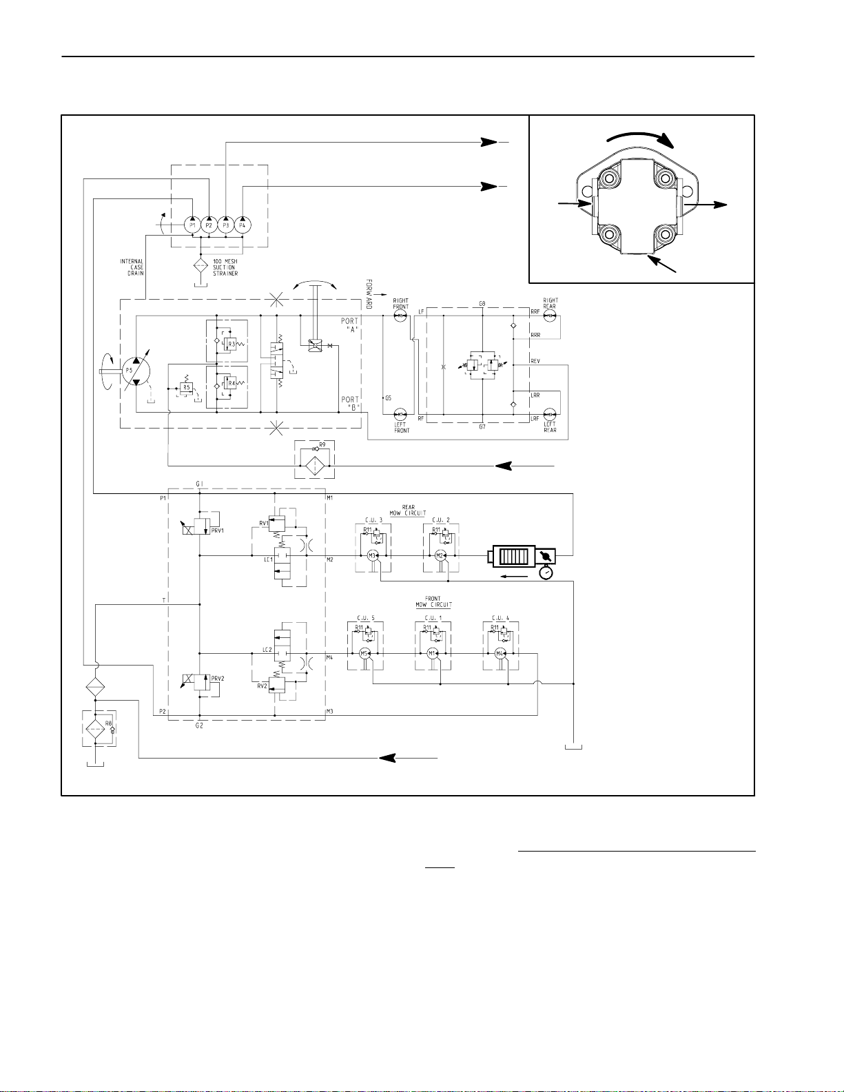
Relief Valve (PRV1) and (PRV2) Pressure Test
PISTON
(TRACTION)
PUMP
TO STEERING CONTROL VALVEAND CHARGE CIRCUIT
TO LIFT CONTROL MANIFOLD
GEAR
PUMP
BYPASS
VALVE
CROSSTRAX
MANIFOLD
FROM STEERING CONTROL VALVE
TESTER
ROTATION
DIRECTION
MOTOR
INLET
MOTOR
OUTLET
CASE DRAIN
DECK
CONTROL
MANIFOLD
FROM LIFT CONTROL MANIFOLD
Figure 45
The relief valve (PRV1) and (PRV2) pressure test
should be performed tomake surethat thecutting deck
circuit relief pressures are correct.
NOTE: Thefrontcuttingdeckcircuitis protectedbyproportional relief valve (PRV2) in the deck control manifold. The rear cutting deck circuit is protected by
proportional relief valve (PRV1) (see Hydraulic Flow
Diagrams in this chapter).
RELIEF VALV E (PRV1)
TEST SHOWN
Procedure for ReliefValve (PRV1) and (PRV2)
Test
sure
Pres-
1. Make sure hydraulic oil is at normal operating temperature by operating the machine under load for
approximately ten (10) minutes.
2. Park machine on a level surface with the cutting
deckslowered and PTO switch off. Make sure engine is
off and mowspeed limiteris in the mow position.Apply
the parking brake.
Groundsmaster 4300--DHydraulic System Page 4 -- 44
Page 77

3. Read Precautions For Hydraulic Testing in this section.
10.Watchpressuregaugecarefully while slowly closing
the tester flow control valve.As the relief valve lifts,the
pressure gauge needle will momentarily stop.
CAUTION
Beforeopening hydraulic system, operate all hydraulic controls to relieve system pressure and
avoid injury from pressurized hydraulic oil. See
RelievingHydraulic System Pressureinthe General Information section of this chapter.
4. Raise and support operator seat to allow access to
hydraulic deck control manifold.
5. Thoroughlycleanjunctionofhydraulicinlet hoseand
deck motor fitting on left side cutting deck for the relief
valvetobetested.Disconnecthosefromdeckmotorfitting (Fig. 46):
#2 cutting deck (left rear) for relief valve (PRV1)
#4 cutting deck (left front) for relief valve (PRV2)
IMPORTANT: Make sure that the oil flow indicator
arrow on the flow meter is showing that the oil will
flowfrom thedisconnectedhose, throughthe tester
and into the deck motor.
6. Install tester with pressure gauge and flow meter in
series with the disconnected hose and hydraulic fitting
on deck motor. Make sure the flow control valve on
tester is fully open.
NOTE: Oncethe relief valve hasopened, systempres-
sure may continue to increase.
11.As the relief valve lifts, system pressure should be:
Approximately 2500 PSI(175 bar) for relief valve
(PRV1)
Approximately 3500 PSI(241 bar) for relief valve
(PRV2)
12.Open thetesterflow control valve,disengagecutting
decks and stop the engine.
13.If pressure is incorrect, remove PRV valve on mow
manifold andclean or replace valve (see Deck Control
Manifold Service in the Service and Repairs section of
this chapter). Also, if pressure isstill low aftervalve service, check for restriction in pump intake line. Gear
pump (P2) (front cutting deck circuit) and/orpump (P1)
(rear cutting deck circuit) could also be suspected of
wear,damage orinefficiency (see GearPump (P1) and
(P2) Flow Test in this section).
14.After testing is completed, make sure that engine is
stopped, then relieve hydraulic system pressure (see
RelievingHydraulic System Pressure in the General Information section of this chapter). Remove tester from
machine and connect hydraulic hose to deck motor fitting.
System
Hydraulic
7. After installing tester, start engine and run at idle
speed. Check for any hydraulic leakage from test connections and correct before proceeding with test.
8. Move throttle to full speed (3200 RPM).
CAUTION
Keepawayfromcuttingdecks during test toprevent personal injury from rotating blades.
9. Have a second person occupy seat, press PTO
switchto ONandthen movejoysticklever forwardtoengage cutting decks.
IMPORTANT: When performing this test, do not
hold over relief any longer than necessary toobtain
pressure reading.
15.Lower and secure operator seat.
1
2
FRONT OF MACHINE
Figure 46
1. Cutting deck motor (#2 shown)
2. Deck motor inlet hose
Groundsmaster 4300--D Hydraulic SystemPage 4 -- 45
Page 78
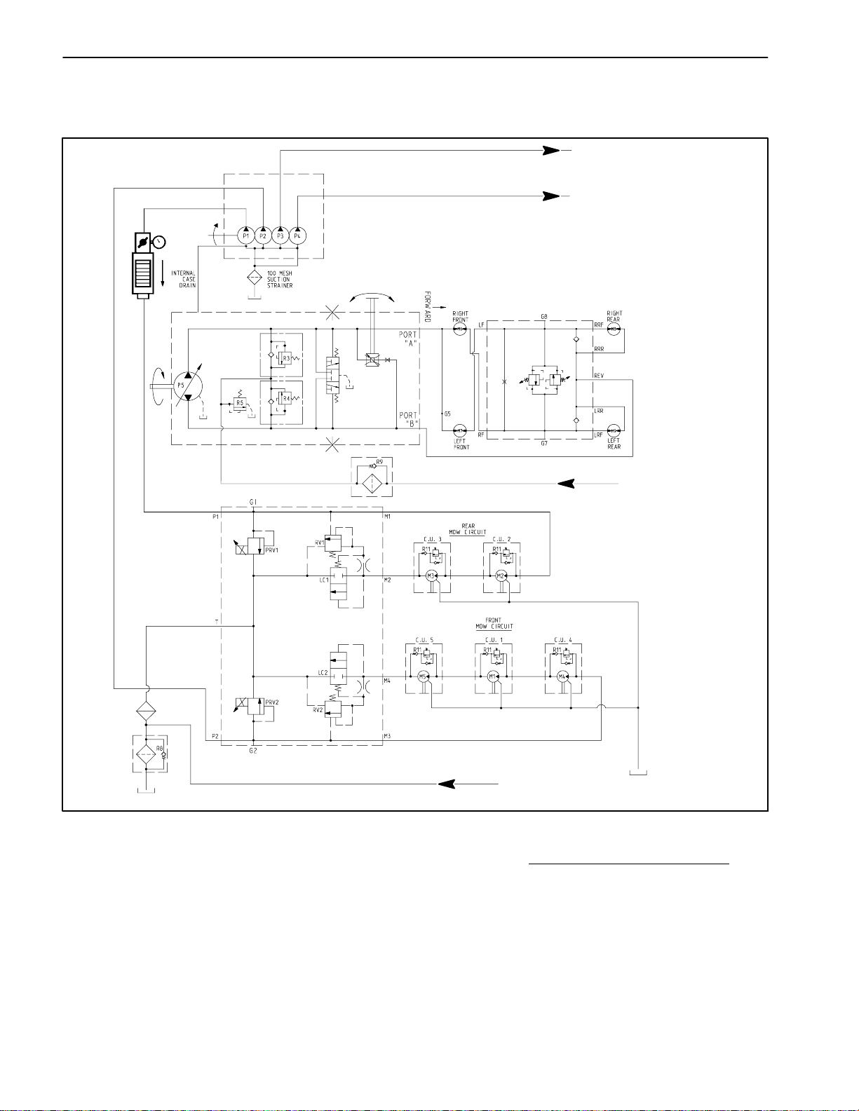
Gear Pump (P1) and (P2) Flow Test
(Using Tester with Pressure and Flow Capabilities)
TO STEERING CONTROL VALVEAND CHARGE CIRCUIT
TO LIFT CONTROL MANIFOLD
TESTER
GEAR
PUMP
BYPASS
VALVE
PISTON
(TRACTION)
PUMP
FROM STEERING CONTROL VALVE
CROSSTRAX
MANIFOLD
GEAR PUMP (P1)
FLOW TEST SHOWN
DECK
CONTROL
MANIFOLD
FROM LIFT CONTROL MANIFOLD
Figure 47
Over aperiod of time, the gears and wear plates in the
gear pump can wear. A worn pump will by-pass oil and
makethe pumplessefficient.Eventually, enoughoilcan
by-passtocausethedecks to stall in heavy cutting conditions. Continued operation with a worn, inefficient
pump can generate excessiveheat and cause damage
to seals and othercomponents inthe hydraulicsystem.
Procedure for Gear Pump (P1) and (P2) Flow
Test
1. Make sure hydraulic oil is at normal operating temperature by operating the machine under load for
approximately ten (10) minutes.
2. Park machine on a level surface with the cutting
deckslowered and PTO switch off. Make sure engine is
off. Apply the parking brake.
Groundsmaster 4300--DHydraulic System Page 4 -- 46
Page 79

3. Read Precautions For Hydraulic Testing in this section.
CAUTION
Beforeopening hydraulic system, operate all hydraulic controls to relieve system pressure and
avoid injury from pressurized hydraulic oil. See
RelievingHydraulic System Pressureinthe General Information section of this chapter.
4. Raise and support operator seat to allow access to
hydraulic pump.
5. Identify suspected faulty pump section to be tested
(Fig.48). Thoroughly clean junction ofgear pump fitting
and hydraulic outlet hose. Disconnect hose frompump
fitting:
Pump section (P1) for rear cutting decks
Pump section (P2) for front cutting decks
11.If flow is less than 12.1 GPM (45.8 LPM) or a pressureof1500PSI(103bar) cannotbeobtained,consider
that a pump problem exists. Check for restriction in
pumpintake line. If intake isnot restricted, removegear
pump and repair or replace pump as necessary (see
Gear Pump andGear Pump Servicein the Serviceand
Repairs section of this chapter).
12.After testing is completed, make sure that engine is
stopped, then relieve hydraulic system pressure (see
RelievingHydraulic System Pressure in the General Information section of this chapter). Remove tester from
machine and connect hydraulic hose to gear pump fitting.
13.Lower and secure operator seat.
1
IMPORTANT: Make sure that the oil flow indicator
arrow onthe flow gauge is showing that the oil will
flowfrom thegearpump, throughthe tester andinto
the hose.
6. Installtesterwith pressure gauges and flowmeter in
series between disconnected hose and gear pump fitting.Make sure theflowcontrol valve ontester is ful-
ly open.
7. After installing tester, start engine and run at idle
speed. Check for any hydraulic leakage from test connections and correct before proceeding with test.
8. Make sure the parking brake is engaged. Move
throttle to full speed(3200 RPM).DO NOT engage the
cutting decks. Use a tachometer to verify that engine
speed is correct.
IMPORTANT: The gear pumpis a positivedisplacement type. If pump flow is completely restricted or
stopped, damage to the pump,tester or other components could occur.
9. While watching pressure gauges, slowly close the
tester flowcontrol valveuntil 1500 PSI (103 bar) is obtained on gauge.
3
1. Gear pump assembly
2. Pump P1 outlet hose
Figure 48
3. Pump P2 outlet hose
2
System
Hydraulic
FLOW TESTER READING TOBE: Apump in good
condition should have a flow of approximately 13.6
GPM (51.2 LPM) at 1500 PSI (103 bar).
10.Open the tester flow control valve and stop the engine. Record test results.
Groundsmaster 4300--D Hydraulic SystemPage 4 -- 47
Page 80

Deck Motor Efficiency Test
(Using Tester with Pressure Gauges and Flow Meter)
ROTATION
DIRECTION
Install tester in series
between fitting and return
hose at motor outlet.
TESTER
CAP
MEASURING
CONTAINER
Disconnect case drain
hose at traction deck
bulkhead
MOTOR
INLET
CASE DRAIN
#5(RHFRONT)DECKMOTOR
EFFICIENCY TEST SHOWN
MOTOR
OUTLET
TO RESERVOIR
MOW CONTROL
MANIFOLD
Figure 49
NOTE: Overaperiodoftime, adeckmotor canwearinternally. A worn motor may bypass oil to its case drain
causing the motor to be less efficient. Eventually,
enough oil loss will cause the deck motor to stall under
heavy cutting conditions. Continued operation with a
worn, inefficient motor can generate excessive heat,
causedamage tosealsand othercomponentsin thehydraulic system and affect quality of cut.
NOTE: One way to find a faulty deck motor is to have
another person observe the machine while mowing in
dense turf. A faultymotor willrun slowerthan other motors,producefewerclippingsand may cause clip marks
(a choppy appearance) on the turf.
Procedure for Deck Motor Efficiency
Test
1. Make sure hydraulic oil is at normal operating temperature by operating the machine under load for
approximately ten (10) minutes.
2. Determine which deck motor is malfunctioning.
3. Park machine on a level surface with the cutting
deckslowered and PTO switch off. Make sure engine is
off and mowspeed limiteris in the mow position.Apply
the parking brake.
4. Read Precautions For Hydraulic Testing in this section.
Groundsmaster 4300--DHydraulic System Page 4 -- 48
Page 81

CAUTION
9. While watching pressure gauges, slowly close flow
control valve on testeruntil apressure of1200 PSI (83
bar) is obtained.
Beforeopening hydraulic system, operate all hydraulic controls to relieve system pressure and
avoid injury from pressurized hydraulic oil. See
RelievingHydraulic System Pressureinthe General Information section of this chapter.
NOTE: The deck motors are connected in series. To
isolate a faulty motor, all motorsin the circuitmay have
to be tested by starting with the upstream motor first.
5. For deck motor to be tested, thoroughlyclean junction of the motorcase drainhose (smalldiameter hose)
where it connects to traction unit bulkhead (not at the
motor)(Fig.50).Disconnectthe casedrain hoseandput
a steel cap on the fitting at the traction unit. Leave the
case drain hose from the motor open and place open
end of disconnected hose into a drain pan.
IMPORTANT: Make sure that the oil flow indicator
arrow onthe flow gauge is showing that the oil will
flow from the deck motor, through the tester and
into the return hose.
6. On deck motor to be tested, thoroughly clean junction of hydraulic returnhose anddeck motorfitting (Fig.
50).Disconnectreturnhosefromthemotor.Installtester
with pressuregauges and flow meter in series with the
motor and disconnected return hose. Make sure the
flow control valve on tester is fully open.
10.After achieving 1200 PSI (83 bar), place disconnected motor case drain hose into a container graduatedin ouncesormilliliters (e.g.Toro#TOR4077)and
collect hydraulic fluid for 15 seconds. After 15 sec-
onds,remove hose end from container.Then move the
PTO switch to OFF, open the tester flow control valve
and stop the engine.
11.Identify amount of oil collected in the container.Record test results.
If flow was greater than 22.4 ounces (662 millili-
ters) (0.7 GPM/2.6 LPM), repair or replace the
tested deck motor (seeCutting Deck Motor Service
in the Service and Repairs section of this chapter).
Ifflow is less than 22.4ounces (662 milliliters) (0.7
GPM/2.6 LPM),the testedmotor doesnot haveexcessive leakage.
12.After testing is completed, make sure that engine is
stopped, then relieve hydraulic system pressure (see
RelievingHydraulic System Pressure in the General Information section of this chapter). Disconnect tester
from motor and returnhose. Connect returnhose to the
deckmotor.Remove plug frommachine bulkhead fitting
and connect case drain hose to the fitting.
13.If necessary, perform motor efficiency test on other
deck motors.
System
Hydraulic
NOTE: Use a graduated container, special tool
TOR4077, to measure case drain leakage (Fig. 49).
7. Startengine and run at idlespeed.Checkforanyhydraulic leakage from test connections and correct before proceeding with test.
CAUTION
Cutting deck bladeswill rotate whenperforming
themotorefficiencytest.K eep awayfromcutting
decksduring testtoprevent personalinjuryfrom
rotating blades. Do not stand in front of the machine.
8. Sit on seat and move throttle to full speed (3200
RPM).PressPTOswitch to ON. Move joystick leverfor-
ward to engage cutting decks.
1. Case drain hose
2. Bulkhead fitting
2
3
1
Figure 50
3. Return hose
Groundsmaster 4300--D Hydraulic SystemPage 4 -- 49
Page 82

Lift Relief Valve (PRV) Pressure Test
TO STEERING
CONTROL VALVE
TO DECK CONTROL MANIFOLD
(FRONT CUTTING UNITS)
TO DECK CONTROL MANIFOLD
(REAR CUTTING UNITS)
PUMP (P5)
INTERNAL
CASE
DRAIN
FROM MOW CONTROL
MANIFOLD
GEAR
PUMP
PRESSURE
GAUGE
LIFT
CONTROL
MANIFOLD
Figure 51
The lift relief valve (PRV) pressure test should be performed to make surethat the liftcircuit reliefpressure is
correct.
Procedure for Lift Relief Valve (PRV) Pressure
Test
1. Make sure hydraulic oil is at normal operating temperature by operating the machine under load for
approximately ten (10) minutes.
2. Park machine on a level surface with the cutting
deckslowered and PTO switch off. Make sure engine is
off. Apply the parking brake.
3. Read Precautions For Hydraulic Testing in this section.
CAUTION
Beforeopening hydraulic system, operate all hydraulic controls to relieve system pressure and
avoid injury from pressurized hydraulic oil. See
RelievingHydraulic System Pressureinthe General Information section of this chapter.
4. Gain access to hydraulic lift control manifold by removing the operator floorplate. The liftcontrol manifold
is attached to a framebracket under thefloor plate (Fig.
52).
Groundsmaster 4300--DHydraulic System Page 4 -- 50
Page 83

5. Thoroughlycleantest port (G4) on bottom oflift control manifold. Connect a 5000 PSI (350 bar) pressure
gauge to test port.
6. After installing pressure gaugeto manifold testport,
startengineandrunatidlespeed.Checkforanyhydraulicleakagefromtestconnectionsandcorrectbeforeproceeding with test.
7. Move throttle to full speed (3200 RPM).
2
3
4
IMPORTANT: Do not allow pressureto exceed2500
PSI (172 bar).
IMPORTANT: While performing this test, hold joystick lever in the raise position only long enough to
get a system pressure reading. Holding the lever in
raise for an extended period may damage system
components.
8. MakesurethatPTOswitch isOFFandthenpull joystickleverrearwardtopressurizeliftcircuit.Whileholding
lever in the raise (rearward) position, watch pressure
gauge carefully.As the cuttingdecks fully raiseand the
lift relief valve lifts, system pressure should be:
Approximately 2000 PSI (138 bar)
9. Return the joystick lever to the neutral position and
stop the engine.
10.If measured pressure is incorrect, remove pressure
reducingvalve(PRV)fromliftcontrolmanifoldandclean
orreplace valve (see Lift ControlManifoldServiceinthe
Service and Repairs section of this chapter). Also, iflift
circuitpressure islow,checkforrestriction ingearpump
intake line. Internal lift cylinder leakage would also
cause low lift circuit pressure(see Lift Cylinder Internal
LeakageTestinthissection).Gearpump(P4)c ouldalso
besuspected of wear,damage orinefficiency(see Gear
Pump (P4) Flow Test in this section).
FRONT
1. Lift control manifold
2. SV1 solenoid
Figure 52
3. SV2 solenoid
4. PRV solenoid
1
System
Hydraulic
11.After testing is completed, make sure that engine is
stopped, then relieve hydraulic system pressure (see
RelievingHydraulic System Pressure in the General Information section ofthis chapter). Disconnectpressure
gauge from lift control manifold test port.
Groundsmaster 4300--D Hydraulic SystemPage 4 -- 51
Page 84

Gear Pump (P4) Flow Test
(Using Tester with Pressure Gauges and Flow Meter)
TO STEERING
CONTROL VALVE
TO DECK CONTROL MANIFOLD
(FRONT CUTTING UNITS)
TO DECK CONTROL MANIFOLD
(REAR CUTTING UNITS)
PUMP (P5)
INTERNAL
CASE
DRAIN
GEAR
PUMP
TESTER
FROM MOW CONTROL
MANIFOLD
Figure 53
The gear pump (P4) flow test should be performed to
make sure thatthe cuttingdeck liftcircuit has adequate
hydraulic flow.
Procedure for Gear Pump (P4) Flow
Test
1. Make sure hydraulic oil is at normal operating temperature by operating the machine under load for
approximately ten (10) minutes.
2. Park machine on a level surface with the cutting
deckslowered and PTO switch off. Make sure engine is
off. Apply the parking brake.
LIFT
CONTROL
MANIFOLD
3. Read Precautions For Hydraulic Testing in this section.
CAUTION
Beforeopening hydraulic system, operate all hydraulic controls to relieve system pressure and
avoid injury from pressurized hydraulic oil. See
RelievingHydraulic System Pressureinthe General Information section of this chapter.
Groundsmaster 4300--DHydraulic System Page 4 -- 52
Page 85

4. Raise and support operator seat to allow access to
hydraulic pump.
5. Thoroughly clean both ends of the hydraulic hose
that connects gear pump (P4) outlet (Fig. 54) and lift
control manifold P4 port. Remove hydraulic hose. Access to hydraulic hose atlift control manifoldcan be obtained from below the machine.
IMPORTANT: Make sure that the oil flow indicator
arrow on the flow meter is showing that the oil will
flow from pump (P4), through the tester and to the
lift control manifold.
6. Installtesterwith pressure gauges and flowmeter in
placeofthe removed hydraulic hose. Connect testerinlet hose to the pump fitting. Connect the tester outlet
hose to the lift control manifold fitting. Make sure the
flow control valve on tester is fully open.
7. Makesure thatthetraction pedalisin neutralandthe
parking brake is engaged.
8. Startengine and run at idlespeed.Checkforanyhydraulic leakage from test connections and correct before proceeding with test.
9. Move throttle to full speed (3200 RPM).Usea
tachometer to verify that engine speed is correct.
IMPORTANT: The gear pumpis a positivedisplacement type. If pump flow is completely restricted or
stopped, damage to the pump,tester or other components could occur.
13.After testing is completed, make sure that engine is
stopped, then relieve hydraulic system pressure (see
RelievingHydraulic System Pressure in the General Information section of this chapter). Remove tester and
connectremoved hydraulic hosetogear pump (P4)outlet and lift control manifold P port.
14.Lower and secure operator seat.
1
2
Figure 54
1. Gear pump (P4) 2. Hydraulic hose
System
Hydraulic
10.While carefully watching pressure gauges, slowly
closethetesterflowcontrolvalve until1000 PSI(70bar)
is obtained on gauge.
FLOW TESTER READING TOBE: Apump in good
condition should have a flow of approximately 3.2
GPM (11.9 LPM) at 1000 PSI (70 bar).
11.Open the tester flow control valve, stop engine and
record test results.
12.If flowislessthan2.8 GPM (10.6 LPM) or apressure
of 1000 PSI (70 bar) cannot be obtained, considerthat
apump problem exists. Check for restriction in pump intake line. If intake is not restricted, remove gear pump
and repair or replace pump as necessary (see Gear
Pump in the Service and Repairs section of this chapter).
NOTE: Iftheflowfromgearpump(P4)islow,theoperation of all lift cylinders will be affected.
Groundsmaster 4300--D Hydraulic SystemPage 4 -- 53
Page 86

Lift Cylinder Internal Leakage Test
TO DECK CONTROL MANIFOLD
(FRONT CUTTING UNITS)
TO STEERING
CONTROL VALVE
TO DECK CONTROL MANIFOLD
(REAR CUTTING UNITS)
PUMP (P5)
INTERNAL
CASE
DRAIN
FROM MOW CONTROL
MANIFOLD
GEAR
PUMP
(PARTIALL Y
RAISED)
PLUG CAP
CHECK FOR
CYLINDER
EXTENDING
LIFT
CONTROL
MANIFOLD
Figure 55
The lift cylinder internal leakage test should be performedifacuttingdeckraiseandlowerproblemisidentified. This test will determine if a lift cylinder is faulty.
NOTE: Cuttingdeckraise/lowercircuitoperation willbe
affected by lift cylinderbinding, extra weighton the cutting decks and/or bindingof lift components. Makesure
that these items are checkedbefore proceedingwith lift
cylinder internal leakage test.
Procedure for Lift Cylinder Internal Leakage
Test:
NOTE: When performing the lift cylinder internal leak-
age test, thecutting decks should be attachedto the lift
arms.
LEFT FRONT (#4) LIFT CYLINDER TEST SHOWN
1. Parkmachine on a level surface withthePTOswitch
OFF.Positionthecuttingdecksintheturn--aroundposition and turn the engine off. Apply the parking brake.
2. For the lift cylinder that is to be tested, use a jack to
raise the lift arm slightly. Thiswill removethe load from
the lift cylinder and relieve lift cylinder hydraulic pressure. Leave thejack under thelift arm tosupport the lift
arm and to prevent the lift arm from lowering.
NOTE: If either ofthe rear lift cylindersis beingtested,
both rear lift arms need to be supported.
3. Thoroughlyclean the area aroundthe endof the hydraulichoseatthe rodendofthelift cylinder.Disconnect
the hydraulic hose from the lift cylinder rod end fitting
(Fig. 56).
Groundsmaster 4300--DHydraulic System Page 4 -- 54
Page 87

IMPORTANT: When capping lift cylinder fitting and
hydraulic hose end, use a steel cap and plug to ensure that fluid leakage will not occur. Plastic plugs
will not hold hydraulic pressure that will be developed during this test procedure.
4. Place a steel cap on the open lift cylinder fitting to
sealthe lift cylinder.Also, install a steel plugin theopen
endofthedisconnectedhoseto preventleakage orcontamination.
5. Slowly lower the jack and remove it from under the
lift arm. Thecutting deck should settle slightlyand then
be supported by the capped lift cylinder.
6. Markthepositionoftheliftcylinderrod attheliftcylinder head with a piece of tape (Fig. 57).
7. Leave the machine parked for two (2) hours and
monitor the lift cylinder. The weight of the cutting deck
may cause the lift cylinderto gradually extend. Use the
tape location to determine lift cylinder rod movement
(Fig. 58).
A. If lift cylinder rod movement is less than 1.250”
(31.7mm)aftertwo(2)hours,makesurethat thecutting deck hasnot settled tothe ground. Ifthe cutting
deckis still suspended aftertwo(2)hoursand lift cylinder rod movement is less than 1.250” (31.7 mm),
consider that the lift cylinder is in good condition. A
cylinder in good,usable condition willshow minimal
movement.
B. Rodmovement in excess of 1.250”(31.7mm)after two (2) hours indicates that the lift cylinder may
have internal seal damage or excessive wear. Remove and inspect the lift cylinder (see Lift Cylinder
and Lift CylinderService in the Service andRepairs
section of this chapter).
Figure 56
1. Lift cylinder (#5 shown)
2. Cylinder rod end fitting
Figure 57
1. Lift cylinder rod
2. Lift cylinder head
3
2
1
3. Hydraulic hose
3
3. Tape (initial position)
1
System
Hydraulic
2
8. Once lift cylinder condition has been determined,
use a jackto raisethe lift armslightly whichwill remove
the load from the lift cylinder. Leave the jack to support
the lift armand to prevent it from lowering. Remove the
cap from the cylinder fitting and the plug from the hydraulichose.Connect the hydraulic hose to the lift cylinder fitting.
9. Carefully remove jack from under the lift arm. Start
engineandoperateliftcylindersthroughseveral up and
down cycles. Stop the engine and check for any leakage.
10.If needed, repeat steps2 through 10 forother lift cylinders.
1. Tape (after 2 hours) 2. Cylinder rod movement
11.After testingis complete, check oil levelin hydraulic
reservoir and adjust if necessary.
Groundsmaster 4300--D Hydraulic SystemPage 4 -- 55
2
1
Figure 58
Page 88

Steering Relief Valve (R10) Pressure Test
TO DECK CONTROL MANIFOLD
(FRONT CUTTING UNITS)
TO DECK CONTROL MANIFOLD
(REAR CUTTING UNITS)
PUMP (P5)
INTERNAL
CASE
DRAIN
TO LIFT CONTROL
MANIFOLD
GEAR
PUMP
TO TRACTION
CHARGE CIRCUIT
TP
OUT IN
STEERING WHEEL TURNED
FOR RIGHT TURN
Figure 59
STEERING
CONTROL
VALVE
R
R10
V1
L
PRESSURE
GAUGE
STEERING
CYLINDER
Groundsmaster 4300--DHydraulic System Page 4 -- 56
Page 89

The s teering relief v alve (R10) pressuretest shouldbe
performed to make sure that the steering circuit relief
pressure is correct.
12.If specification is not met, inspect steering control
valve(seeSteeringControlValveServiceintheService
and Repairs section of this chapter).
Procedure for Steering Relief Valve Pressure
1. Make sure hydraulic oil is at normal operating temperature by operating the machine under load for
approximately ten (10) minutes.
2. Park machine on a level surface with the cutting
deckslowered and PTO switch off. Make sure engine is
off. Apply the parking brake.
3. Read Precautions For Hydraulic Testing in this section.
Test:
CAUTION
Beforeopening hydraulic system, operate all hydraulic controls to relieve system pressure and
avoid injury from pressurized hydraulic oil. See
RelievingHydraulic System Pressureinthe General Information section of this chapter.
4. Thoroughlycleantheareaaroundthehydraulichose
at the rod end of the steering cylinder (Fig. 60).
5. Remove hydraulic hose from the fitting on the rod
end of the steering cylinder.
13.After testing is completed, make sure that engine is
stopped, then relieve hydraulic system pressure (see
RelievingHydraulic System Pressure in the General Information section of this chapter). Remove tee fitting
and pressure gauge from hydraulic hose and steering
cylinder.Connect hydraulic hose to steering cylinderfitting.
1
2
Figure 60
1. Steering cylinder 2. Rod end fitting
System
Hydraulic
6. Installatee fittingbetween thedisconnectedhydraulic hose and the steering cylinder fitting. Install a 5000
PSI (350 bar) pressure gauge to the tee fitting.
7. Afterinstalling pressure gauge, startengine and run
atidlespeed.Check for any hydraulic leakage from test
connections and correct before proceeding with test.
8. Move throttle to full speed (3200 RPM).
IMPORTANT: Hold steering wheel at full lock only
long enough to get a system pressure reading.
Holding the steering wheel against the stop for an
extended period may damage the steering control
valve.
9. Watch pressure gauge carefully while turning the
steering wheel for a lefthand turn (counter--clockwise)
and holding.
10.System pressure should be approximately 1000 PSI
(70bar) as the relief valve lifts. Return steering wheel to
the neutral position.
11.Shut off engine. Record test results.
Groundsmaster 4300--D Hydraulic SystemPage 4 -- 57
Page 90

Steering Cylinder Internal Leakage Test
STEERING WHEEL
TURNED FOR
RIGHT TURN
R10
STEERING
CONTROL
VALVE
STEERING
CYLINDER
(FULLYEXTENDED)
Figure 61
The steering cylinder internal leakage test should be
performed if a steering problem is identified. This test
will determine if the steering cylinder is faulty.
CAP
LOOK FOR LEAKAGE
NOTE: Steering circuit operation will be affected by
rear tire pressure, steering cylinder binding, extra
weightonthevehicleand/orbindingofrearaxlesteering
components. Make sure that these items are checked
before proceeding with steering cylinder internal leakage test.
Groundsmaster 4300--DHydraulic System Page 4 -- 58
Page 91

Procedure for Steering Cylinder Internal Leakage
Test:
1. Make sure hydraulic oil is at normal operating temperature.
2. Park machine on a level surface with the cutting
deckslowered and PTO switch off. Make sure engine is
off. Apply the parking brake.
1
3. Read Precautions For Hydraulic Testing.
CAUTION
Beforeopening hydraulic system, operate all hydraulic controls to relieve system pressure and
avoid injury from pressurized hydraulic oil. See
RelievingHydraulic System Pressureinthe General Information section of this chapter.
4. Turnthesteering wheelforarightturn (clockwise)so
the steering cylinder rod is fully extended.
5. Thoroughlycleantheareaaroundthehydraulichose
at the rod end of the steering cylinder (Fig. 62).
6. Place a drain pan under the steering cylinder. Removehydraulichosefromthefittingontherodendofthe
steering cylinder. Cap the end of the hose.
7. Remove all hydraulic oil from drain pan. Make sure
that empty drain pan remains under the open fitting of
the steering cylinder.
2
Figure 62
1. Steering cylinder 2. Rod end fitting
System
Hydraulic
8. With the engine off, continue turning the steering
wheelfor a right turn(clockwise) with thesteering cylinderfully extended.Observe theopenfitting onthesteeringcylinder as the wheelisturned.If oil comes outofthe
fitting while turning the steering wheel to the right, the
steeringcylinder has internal leakageand should beinspectedandrepaired(seeSteeringCylinderandSteering Cylinder Servicein theService andRepairs section
of this chapter). Checkdrain pan for anyevidence of oil
that would indicate internal cylinder leakage.
9. Removeplugfromthehydraulichose. Connecthose
to the steering cylinder fitting.
10.If a steering problem existsand the steering cylinder
tested acceptably, the steering control valve requires
service (see Steering Control Valve and Steering Control ValveService in the Service andRepairs section of
this chapter).
11.Check oil level in hydraulic reservoir and adjust if
needed.
Groundsmaster 4300--D Hydraulic SystemPage 4 -- 59
Page 92

Service and Repairs
General Precautions for Removing and Installing Hydraulic System Components
Before Repair or Replacement of Components
1. Before removing any parts from the hydraulic system, park machine on a level surface, engage parking
brake, lower cutting decks and stop engine. Remove
key from the ignition switch.
2. Thoroughlyclean machinebeforedisconnecting, removing or disassembling any hydraulic components.
Make sure hydraulic components, hose connections
andfittingsare thoroughlycleaned.Alwayskeepinmind
the need for cleanliness when working on hydraulic
components.
CAUTION
Before loosening any hydrauliccomponent, operate all hydraulic controls to relieve system
pressure and avoid injury from pressurized hydraulicoil. SeeRelievingHydraulic System Pressure in the General Information section of this
chapter.
3. Operateallhydraulic controlstorelievesystempressure before loosening any hydraulic connection (see
RelievingHydraulic System Pressure in the General Information section).
4. Putcapsor plugsonanyhydrauliclines,hydraulicfittings or components left open or exposed to prevent
contamination.
After Repair or Replacement of Components
1. If a component failure occurred in the closed loop
traction circuit (e.g. piston pump or wheelmotor), filtering the traction circuit is recommended (see Filtering
Closed--Loop Traction Circuit in this section).
2. Ifcomponent failure issevere orhydraulic systemis
contaminated, flush hydraulic system (see Flush Hydraulic System in this section).
3. Lubricate O--rings andseals withclean hydraulic oil
before installing hydraulic components.
4. Make sure all caps or plugs are removed from hydraulic tubes, hydraulicfittings and componentsbefore
reconnecting.
5. Use proper tightening methods when installing hydraulichoses and fittings (see Hydraulic FittingInstallation inthe General Information section of this chapter).
6. After repairs, check control linkages and cables for
proper adjustment, binding or broken parts.
7. Afterrepairs are completed, clean hydrauliccomponents, hose connections and fittings to prevent future
accumulation of dirt and debris on hydraulic components.
8. After disconnecting or replacing anyhydraulic components, operate machine functions slowly until air is
outofsystem(seeHydraulicSystemStartUpinthissection).
5. Before disconnecting hydraulic lines and hoses,
place labels to ensure proper installation after repairs
are completed.
6. Note the position of hydraulic fittings (especially elbow fittings) on hydraulic components before removal.
Mark parts if necessaryto make surethat fittingswill be
aligned properlywhen reinstalling hydraulic hoses and
tubes.
9. Checkfor hydraulic oil leaks. If any leaks are discovered, shut off engine and correct leaks.
10.Check oil level in hydraulic reservoir and addcorrect
oil if necessary.
Groundsmaster 4300--DHydraulic System Page 4 -- 60
Page 93

Check Hydraulic Lines and Hoses
CAUTION
Keep body and hands away from pin hole leaks
or nozzles that eject hydraulic fluid under high
pressure. Use paperor cardboard,not hands, to
search for leaks. Hydraulic fluid escaping under
pressure can have sufficient force to penetrate
the skin and cause serious injury. If fluid is injected into the skin, it must be surgically removed within a few hours by a doctor familiar
withthistypeofinjury. Gangrenemay resultfrom
such an injury.
Flush Hydraulic System
Check hydraulic lines and hosesdaily forleaks, kinked
lines, loose mounting supports, wear, loose fittings or
deterioration.Make allnecessaryrepairs beforeoperating the machine.
IMPORTANT: Flush the hydraulic system any time
thereis a severe component failure or the system is
contaminated. Contaminated oil may appear milky
or black or may contain metal particles.
IMPORTANT: If a component failureoccurred in the
closed loop traction circuit (e.g. piston pump or
wheel motor), filtering the traction circuit isrecommended.SeeFiltering Closed--LoopTractionCircuit
in this section.
1. Park machine on a level surface. Lower cutting
decks, stop engine, engage parkingbrake andremove
key from ignition switch.
2. Drain hydraulic reservoir. Remove suction screen
fromreservoirandclean thoroughly.Considerremoving
and cleaning reservoir if necessary.
3. Clean area around the mounting areas of the hydraulic filters. Remove and discard hydraulic filters.
4. Drainentire hydraulicsystem.Drainall hoses,tubes
andcomponents while thesystemiswarm. Flush hoses
and tubes to remove any contamination.
7. Disconnect wire harness electrical connector from
theenginefuelstop solenoid to prevent the engine from
starting.
8. Make sure traction pedal is in neutral and the PTO
switch isOFF. Turn ignition key switch to start; engage
starter for ten (10) seconds to prime hydraulic pumps.
Wait fifteen (15) seconds to allow the starter motor to
cool and then repeat cranking procedure again.
9. Connect wire harness electrical connector to fuel
stop solenoid to allow engine to start.
10.Startengineand letit idleatlowspeedfor aminimum
of two (2) minutes.
11.Increase engine speed to high idle for minimum of
one (1) minute under no load.
12.Rotate steering wheel in both directions several
times. Raise and lower cutting decks several times.
13.Move PTOswitch toONto engagecuttingdecksand
let them run for several minutes. Move PTO switch to
OFF.
System
Hydraulic
5. Makesure the mounting surfaces of the hydraulic filtersareclean. Applyclean hydraulicoiltogasketonnew
filters. Screw filters on until gasket contacts mounting
plate, then tighten filter three quarters of a turn.
IMPORTANT: Use only hydraulic fluids specified in
Operator’sManual.Other fluidscouldcausesystem
damage.
6. Fill hydraulic reservoir with new hydraulic oil.
Groundsmaster 4300--D Hydraulic SystemPage 4 -- 61
14.Shut off engine and check for hydraulic oil leaks.
Check oil level inhydraulic reservoir andadd correctoil
if necessary.
15.Operate the machine fortwo (2) hoursunder normal
operating conditions.
16.Checkconditionofhydraulicoil.Ifthefluidshowsany
signsofcontamination,repeatsteps 1through14again.
17.Resume normal operation andfollowrecommended
maintenance intervals.
Page 94

Filtering Closed--Loop Traction Circuit
Filteringof a closed--loophydraulicsystemafter a major
component failure (e.g.traction (piston) pump orwheel
motor)is a requirement to preventdebris from transmitting throughout the system. If a closed--loop hydraulic
systemfilteringtoolisnotusedtoensuresystemcleanliness, repeat failures, aswell assubsequent damage to
other hydraulic components in theaffected system,will
occur. To effectively remove contamination from
closed--looptraction circuit, useoftheTorohighflow hydraulic filter and hydraulic hose kits are recommended
(see Special Tools in this chapter).
1. Parkmachineonalevelsurfacewithenginestopped
and key removed from ignition switch.
2. Raise and support machineso allwheels are off the
ground(see Jacking Instructions in Chapter 1 --Safety).
NOTE: Ifwheel motorwasreplaced,installhigh flow filter to the inletof the new motorinstead ofto the traction
pump fitting. This will prevent system contamination
from entering and damaging the new wheel motor.
3. Thoroughlyclean junction of hydraulic hoseand left
side elbow fitting on bottom of traction pump (Fig. 63).
Disconnect hose from left side pump fitting.
4. Connect Toro high flow hydraulic filter in series betweentraction pump fitting and disconnected hose. Use
hydraulic hosekit (see Special Tools in this chapter) to
connectfiltertomachine.Makesurethatfittingandhose
connections are properly tightened.
IMPORTANT: Use only hydraulic fluids specified in
Operator’sManual.Other fluidscouldcausesystem
damage.
5. Afterinstalling high flowfilter tomachine, checkand
fillhydraulic reservoir with new hydraulic oilasrequired.
7. With engine running atlow idle speed, slowly move
the traction pedal to the forward direction to allow flow
throughthe tractioncircuit andhighflow filter.Keeptraction circuit engaged for five (5) minutes while gradually
increasing both forwardpressure on traction pedal and
engine speed. Monitor filterindicator to make sure that
green color is showing during operation.
8. With engine running at high idle speed and traction
pedalmoved to the forward direction,periodically apply
brakes to increase pressure in traction circuit. While
monitoring filter indicator, continue this process for an
additional five (5) minutes.
IMPORTANT: Ifusing a filterthat is nottheTorohigh
flow filter that is bi--directional, do not press the
traction pedal in the reverse direction. If flow is reversed when using afilter thatis not bi--directional,
debris from the filter will re--enter the traction circuit.
9. With engine running at high idle speed, alternately
movetractionpedalfromforwardtoreverse.Whilemonitoring filter indicator, continuethis processfor an additional five (5) minutes.
10.Shut engine off and remove key from ignition switch.
11.Remove high flow hydraulic filter and hydraulichose
kit from machine. Connect hydraulic hose to left side
tractionpump fitting. Make sure to properly tightenhose
(seeHydraulic Hose and TubeInstallationintheGeneral Information section of this chapter).
12.Lower machine to ground.
13.Check oil level in hydraulic reservoir and addcorrect
oil if necessary.
6. Startengine and run at idlespeed.Checkforanyhydraulic leakage from filter and hose connections. Correct any leaks before proceeding.
CAUTION
Allwheels willbeoff thegroundand rotatingduring this procedure. Make sure machine is well
supported so it will not move and accidentally
fall to prevent injuring anyone around machine.
IMPORTANT: While engaging the traction circuit,
monitor the indicator on the high flow hydraulic filter. If the indicator should show red, either reduce
pressure on the traction pedal or reduce engine
speed to decrease hydraulic flow through the filter.
1
RIGHT
2
FRONT
1. Traction pump
2. RH elbow fitting
3. Hyd hose (forward)
4
3
5
Figure 63
4. LH elbow fitting
5. Hyd hose (reverse)
Groundsmaster 4300--DHydraulic System Page 4 -- 62
Page 95

Hydraulic System Start--up
NOTE: Wheninitially startingthehydraulicsystemwith
new or rebuilt components such as pumps, wheel motors or lift cylinders,it is importantthat thisstart--up procedure be used.This procedure reducesthe chance of
damaging the systemor its components from notpurging the system of air.
1. After the hydraulic system components have been
properly installed and ifthe traction pumpwas rebuilt or
replaced, make sure traction pump housing is at least
half full of clean hydraulic oil.
2. Makesureallhydraulicconnectionsandlinesaresecured tightly.
3. Drain, flush and refill hydraulic system and change
hydraulic oil filters if component failure was severe or
systemiscontaminated(seeFlushHydraulicSystemin
this section).
4. Make sure hydraulic reservoir is full.Add correctoil
if necessary.
5. Checkcontrol linkageforproper adjustment,binding
or broken parts.
6. Disconnect wire harness electrical connector from
theenginefuelstop solenoid to prevent the engine from
starting.
7. Make sure traction pedal is in neutral and the PTO
switch isOFF. Turn ignition key switch to start; engage
starter for ten (10) seconds to prime hydraulic pumps.
Wait fifteen (15) seconds to allow the starter motor to
cool and then repeat cranking procedure again.
8. Connect wire harness electrical connector to fuel
stop solenoid to allow engine to start.
9. Make sure traction pedal is in neutral and the PTO
switch is OFF. Start engine and run it at low idle. The
chargepump shouldpickup oilandfill thehydraulicsystem. If thereis no indicationof fill inthirty (30) seconds,
stop the engine and determine the cause.
10.If the tractionpump was replaced or rebuilt, run the
traction unit so thewheels turnslowly forten (10)minutes.
11.Operate the traction unit(including steering and cutting deck lift/lower) by gradually increasing the work
load to full over a ten (10) minute period.
12.Stop themachine. Check oillevel in hydraulicreservoir and add correct oil if necessary. Check hydraulic
components for leaks and tighten any loose connections.
System
Hydraulic
Groundsmaster 4300--D Hydraulic SystemPage 4 -- 63
Page 96

Hydraulic Reservoir
25
26 to 32 ft--lb
(36to43N--m)
RIGHT
2
105 to 115 ft--lb
(143 to 155 N--m)
5
3
16
1
17
17
18
9
10
11
12
13
12
23
13
24
14
6
4
22
8
14
7
26
20
15
22
26
24
FRONT
1. Suction strainer
2. Tank cap
3. Hydraulic reservoir
4. Adapter
5. Manifold
6. O--ring
7. Hydraulic hose
8. O--ring
9. Cap screw
19
Figure 64
10. Flat washer
11. Bumper
12. Washer head screw (2 used)
13. Clamp (2 used)
14. Flange nut
15. Flange head screw(2 used)
16. O--ring
17. Hose clamp (2 used)
18. Hydraulic hose
19. Oil filter
20. Filter head
21. Hydraulic hose
22. O--ring
o
23. 90
hydraulic fitting
24. O--ring
25. Screen filter
26. Hydraulic fitting
21
Groundsmaster 4300--DHydraulic System Page 4 -- 64
Page 97

Removal (Fig. 64)
Installation (Fig. 64)
1. Parkthemachineona levelsurface,engage parking
brake, lower cutting decks and stop engine. Remove
key from the ignition switch.
2. Thoroughlycleanhydraulic hoseendsandfittingson
hydraulic reservoir to prevent hydraulic system contamination. Label hydraulichoses toassist ininstallation.
3. Disconnect hydraulic hose (item 7) from adapterfittingon bottom of reservoir to allow draining ofreservoir.
Drain reservoir into a suitable container.
4. Disconnect remaining hydraulic hoses from reservoir.Allowhydrauliclines todrain intoasuitablecontainer.Plugorcapopeningsofreservoir andlinestoprevent
contamination.
5. Remove hydraulic reservoir using Figure 64 as a
guide.
6. Remove suction strainerfrom reservoir. DiscardO-ring.
7. Ifhydraulicfittings are to be removedfrom reservoir,
mark fitting orientation to allow correct assembly. Remove fittings from reservoir and discard O--rings.
Inspection (Fig. 64)
1. Clean hydraulic reservoir and suction strainer with
clean solvent.
1. Iffittingswere removed from reservoir,lubricateand
placenew O--rings ontofittings.Install fittingsintoreservoir openings using marks made during the removal
process to properly orientate fittings. Tighten fittings
(see Hydraulic Fitting Installation in the General Information section of this chapter).
2. Lubricate new suction strainer O--ring and install
ontostrainer.Thread suction strainer intohydraulic reservoir andtorque strainer 105 to 115 ft--lb (143 to 155
N--m).
3. Position hydraulic reservoir to machine. Secure reservoir to frame with two (2) clamps (item 13), washer
head screws (item 12) and flange nuts (item 14).
4. Remove all plugs and caps placed inhoses and fittings during the removal process.
5. Install hydraulic hoses to fittings on hydraulic reservoir in positions noted during removal (see Hydraulic
Hose and Tube Installation in the General Information
section of this chapter).
6. Fill hydraulic reservoir with new hydraulic fluid.
7. Operate machine. Check hydrauliclines and fittings
forleaks.Tightenanylooseconnections.Checkhydraulic oil level and adjust if necessary.
System
Hydraulic
2. Inspecthydraulic reservoir for leaks,cracks orother
damage.
Groundsmaster 4300--D Hydraulic SystemPage 4 -- 65
Page 98

Hydraulic Pump Drive Shaft
RIGHT
FRONT
5
8
3
2
9
6
9
7
4
Permatex
Threadlocker
10
34 to 42 ft--lb
(46to56N--m)
1
Antiseize
Lubricant
1. Piston (traction) pump
2. Flange nut (2 used)
3. Flange head screw (2 used)
4. Guard hoop
Figure 65
5. Cap screw (2 used)
6. Engine flywheel
7. Cap screw (6 used)
8. Drive shaft assembly
9. Flange nut (4 used)
10. Flange head screw(2 used)
Groundsmaster 4300--DHydraulic System Page 4 -- 66
Page 99

Removal (Fig. 65)
Installation (Fig. 65)
1. Parkthemachineona levelsurface,engage parking
brake, lower cutting decks and stop engine. Remove
key from the ignition switch.
2. Removetwo(2) flange head screws andflange nuts
that secure drive shaft guard hoop (item4) to machine
frame. Remove guard.
3. Removetwo (2) cap screws (item5) and flange nuts
(item9)thatsecuredrive shaftyoketopistonpumpinput
shaft.
4. Removesix (6) capscrews(item7) that secure drive
shaft flange to engine flywheel.
5. Remove drive shaft assembly from machine.
Drive Shaft Cross and Bearing Service (Fig. 66)
1. Remove snap rings that secure bearings in yokes.
IMPORTANT: Yokes must be supported when removing and installing bearings toprevent damage.
2. Use a press to remove cross and bearings from
yokes. Thoroughly clean drive shaft yokes.
3. To install new cross and bearings:
A. Applyacoatingofgreaseto bearing bores in end
yoke and shaft yoke.
1. Applyantiseizelubricanttotractionpump inputshaft.
2. Positiondriveshaft assemblytoengineandpumpinput shaft.
3. Apply Permatex Blue Gel Threadlocker (or equivalent) to threadsof capscrews (item 7)that securedrive
shaft flange to engine flywheel. Secure drive shaft
flange to flywheel with six (6) cap screws (item 7).
Torque cap screwsfrom 34 to42 ft--lb (46 t o 56 N--m).
4. Slidedrive shaftyoke on pump input shaft so yoke is
flush with end of input shaft. Securedrive shaft yoke to
pump input shaft with two (2) cap screws (item 5) and
flange nuts (item 9).
5. Position drive shaft guard hoop to machine frame
and secure with two (2) flange headscrews andflange
nuts.
6. Lubricate grease fittings on drive shaft.
4
3
2
1
System
Hydraulic
B. Press one bearing partially into yoke.
C. Insert cross into yoke and bearing.
D. Holdcrossinalignment and press bearinginuntil
it hits the yoke.
E. Install snap ring into yoke groove to secure
installed bearing.
F. Place second bearing into yoke bore and onto
crossshaft.Pressbearing into yoke and secure with
snap ring.
G. Repeat procedure for other yoke.
H. Greasecross untilgreasecomesoutofallfour(4)
cups.
4. Makesurethatassembled joint moves without bind-
ing. Slight binding can usually be eliminated by lightly
rapping the yoke lugswith a soft facedhammer. If binding continues, disassemble joint to identify source of
binding.
1. End yoke
2. Cross and bearing kit
3
Figure 66
3. Snap ring (4 used)
4. Shaft yoke
Groundsmaster 4300--D Hydraulic SystemPage 4 -- 67
Page 100

Hydraulic Pump Assembly
16
17
35
34
29
8
25
18
26
33
12
10
17
15
19
32
38
33
5
36
32
22
24
1
2
21
30
4
23
9
15
3
15
14
11
21
37
25
Antiseize
Lubricant
20
39
23
31
13
7
5
6
RIGHT
FRONT
1. Drive shaft assembly
2. Cap screw (2 used)
3. Flange head screw (2 used)
4. Hydraulic pump assembly
5. O--ring
o
6. 90
hydraulic fitting (2 used)
7. Hydraulic hose (2 used)
8. Pump support bracket
9. Flange nut (2 used)
10. Traction cable bracket
11. Flange head screw (2 used)
12. Carriage screw (2 used)
13. Hydraulic hose
6
25
28
Figure 67
14. Guard hoop
15. Flange nut (6 used)
16. Manifold
17. Hose clamp (2 used)
18. Hydraulic hose
19. Hydraulic fitting
20. Neutral switch
21. O--ring
o
hydraulic fitting
22. 90
23. O--ring
24. Hydraulic tube
25. O--ring
26. Hydraulic fitting
25
27
27. Hydraulic hose
28. Hydraulic hose
29. Frame bracket
30. Flange head screw(2 used)
31. Hydraulic tube
32. O--ring
33. O--ring
34. Flat washer (2 used)
35. Lock nut (2 used)
36. O--ring
37. Hydraulic fitting (2 used)
38. Hydraulic fitting
39. Hydraulic fitting
Groundsmaster 4300--DHydraulic System Page 4 -- 68
 Loading...