

Toro 72212, 430, 420 Operator's Manual
Form No. 3353-250
420 and 430 Garden Tractor
Model No. 72211 —Serial No. 250000001 and Up
Model No. 72212 —Serial No. 250000001 and Up
Register your product at www.Toro.com Original Instructions (EN)

T his spark ignition system complies with Canadian
ICES-002
Contents
Introduction . . . . . . . . . . . . . . . . . . . . . . . . . . . . . . . . . . . . . . . . . . . . . . . . . . . . . . . . . 2
Safety . . . . . . . . . . . . . . . . . . . . . . . . . . . . . . . . . . . . . . . . . . . . . . . . . . . . . . . . . . . . . . . . . . 4
Safe Operating Practices . . . . . . . . . . . . . . . . . . . . . . . . . . . 4
T oro Riding Mo w er Safety . . . . . . . . . . . . . . . . . . . . . . . . 5
Slope Char t . . . . . . . . . . . . . . . . . . . . . . . . . . . . . . . . . . . . . . . . . . . 6
Safety and Instr uctional Decals . . . . . . . . . . . . . . . . . 7
Setup . . . . . . . . . . . . . . . . . . . . . . . . . . . . . . . . . . . . . . . . . . . . . . . . . . . . . . . . . . . . . . . . . 10
1 Installing the Steering W heel . . . . . . . . . . . . . . . . 11
2 Installing the Seat . . . . . . . . . . . . . . . . . . . . . . . . . . . . . . . . 11
3 Acti v ating and Installing the
Batter y . . . . . . . . . . . . . . . . . . . . . . . . . . . . . . . . . . 12
4 Installing the F ront Tires . . . . . . . . . . . . . . . . . . . . . . 13
5 Installing the R ear W heels . . . . . . . . . . . . . . . . . . . . 13
6 Chec king the Tire Pressure and
T ractor Lubrication . . . . . . . . . . . . . . . . . 14
7 R eading the Man ual and Viewing the
Safety Video . . . . . . . . . . . . . . . . . . . . . . . . . . 14
8 Chec king the Safety System . . . . . . . . . . . . . . . . . . 14
9 T est Dri v e the T ractor . . . . . . . . . . . . . . . . . . . . . . . . . 14
Product Ov er view . . . . . . . . . . . . . . . . . . . . . . . . . . . . . . . . . . . . . . . . . . . . . . . 16
Controls . . . . . . . . . . . . . . . . . . . . . . . . . . . . . . . . . . . . . . . . . . . . . . 17
Operation . . . . . . . . . . . . . . . . . . . . . . . . . . . . . . . . . . . . . . . . . . . . . . . . . . . . . . . . . . 19
R ecommended Gasoline . . . . . . . . . . . . . . . . . . . . . . . . 19
Chec k Engine Oil Lev el . . . . . . . . . . . . . . . . . . . . . . . . . . 20
T hink Safety First . . . . . . . . . . . . . . . . . . . . . . . . . . . . . . . . . . 20
Operating the P arking Brak e . . . . . . . . . . . . . . . . . . . 20
Star ting and Stopping the Engine . . . . . . . . . . . . . 20
Operating the P o w er T ak e Off
(PTO) . . . . . . . . . . . . . . . . . . . . . . . . . . . . . . . . . . . 21
T he Safety Interloc k System . . . . . . . . . . . . . . . . . . . . 21
Dri ving F orw ard or Bac kw ard . . . . . . . . . . . . . . . . . 23
Stopping the Mac hine . . . . . . . . . . . . . . . . . . . . . . . . . . . . 23
Operating the Attac hment Lift
Lev er . . . . . . . . . . . . . . . . . . . . . . . . . . . . . . . . . . . . 24
Using the Attac hment P o w er Lift . . . . . . . . . . . . . 24
P ositioning the Seat . . . . . . . . . . . . . . . . . . . . . . . . . . . . . . . 24
Using the Headlights . . . . . . . . . . . . . . . . . . . . . . . . . . . . . 25
P ositioning the Tilt Steering
W heel . . . . . . . . . . . . . . . . . . . . . . . . . . . . . . . . . . . 25
Pushing the Mac hine b y Hand . . . . . . . . . . . . . . . . . 25
Using the Cr uise Control . . . . . . . . . . . . . . . . . . . . . . . . 26
Maintenance . . . . . . . . . . . . . . . . . . . . . . . . . . . . . . . . . . . . . . . . . . . . . . . . . . . . . . . 27
R ecommended Maintenance
Sc hedule(s) . . . . . . . . . . . . . . . . . . . . . . . . . . . . . . . . . . . 27
Lubrication . . . . . . . . . . . . . . . . . . . . . . . . . . . . . . . . . . . . . . . . . . . . . . . . . 27
Greasing and Lubrication . . . . . . . . . . . . . . . . . . . . . . . 27
Engine Maintenance . . . . . . . . . . . . . . . . . . . . . . . . . . . . . . . . . . . . 28
Ser vicing the Engine Oil . . . . . . . . . . . . . . . . . . . . . . . . . 28
Ser vicing the Air Cleaner . . . . . . . . . . . . . . . . . . . . . . . . 29
Ser vicing the Spark Plug . . . . . . . . . . . . . . . . . . . . . . . . . 30
Fuel System Maintenance . . . . . . . . . . . . . . . . . . . . . . . . . . . . . . 31
Draining T he Fuel T ank . . . . . . . . . . . . . . . . . . . . . . . . . 31
Ser vicing the Fuel Filter . . . . . . . . . . . . . . . . . . . . . . . . . 31
Electrical System Maintenance . . . . . . . . . . . . . . . . . . . . . . . 32
Ser vicing the Fuses . . . . . . . . . . . . . . . . . . . . . . . . . . . . . . . . 32
Ser vicing the Headlights . . . . . . . . . . . . . . . . . . . . . . . . . 32
Ser vicing the Batter y . . . . . . . . . . . . . . . . . . . . . . . . . . . . . . 33
Dri v e System Maintenance . . . . . . . . . . . . . . . . . . . . . . . . . . . . 36
Chec king the Tire Pressure . . . . . . . . . . . . . . . . . . . . . 36
Ser vicing the F ront W heel T oe-In . . . . . . . . . . . . 36
T ransaxle Fluid . . . . . . . . . . . . . . . . . . . . . . . . . . . . . . . . . . . . . 36
Cooling System Maintenance . . . . . . . . . . . . . . . . . . . . . . . . . 37
Cleaning the Cooling System . . . . . . . . . . . . . . . . . . . 37
Brak e Maintenance . . . . . . . . . . . . . . . . . . . . . . . . . . . . . . . . . . . . . . 37
Ser vicing the Brak e . . . . . . . . . . . . . . . . . . . . . . . . . . . . . . . . 37
Storag e . . . . . . . . . . . . . . . . . . . . . . . . . . . . . . . . . . . . . . . . . . . . . . . . . . . . . . . . . . . . . . 38
Cleaning and Storag e . . . . . . . . . . . . . . . . . . . . . . . . . . . . . 38
T roubleshooting . . . . . . . . . . . . . . . . . . . . . . . . . . . . . . . . . . . . . . . . . . . . . . . . . 39
Sc hematics . . . . . . . . . . . . . . . . . . . . . . . . . . . . . . . . . . . . . . . . . . . . . . . . . . . . . . . . . 41
Introduction
R ead this infor mation carefully to lear n ho w to operate
and maintain y our product properly and to a v oid injur y
and product damag e . Y ou are responsible for operating
the product properly and safely .
Y ou ma y contact T oro directly at www .T oro .com for
product and accessor y infor mation, help finding a
dealer , or to register y our product.
W henev er y ou need ser vice , g en uine T oro par ts , or
additional infor mation, contact an A uthorized Ser vice
Dealer or T oro Customer Ser vice and ha v e the model
and serial n umbers of y our product ready . Figure 1
identifies the location of the model and serial n umbers
on the product. W rite the n umbers in the space
pro vided.
Figure 1
1. Model and serial number plate
© 2004—The Toro® Company
8111 Lyndale Avenue South
Bloomington, MN 55420
Contact us at www.Toro.com.
2
Printed in the USA
All Rights Reserved

Model No.
Serial No.
T his man ual identifies potential hazards and has
safety messag es identified b y the safety aler t symbol
( Figure 2 ), whic h signals a hazard that ma y cause
serious injur y or death if y ou do not follo w the
recommended precautions .
Figure 2
1. Safety alert symbol.
T his man ual uses tw o other w ords to highlight
infor mation. Impor tant calls attention to special
mec hanical infor mation and Note emphasizes g eneral
infor mation w or th y of special attention.
3

Safety
T his mac hine meets or ex ceeds the B71.1-1998
specifications of the American National Standards
Institute , in effect at the time of production. Ho w ev er ,
improper use or maintenance b y the operator or o wner
can result in injur y . T o reduce the potential for injur y ,
comply with these safety instr uctions and alw a ys pa y
attention to the safety aler t symbol, whic h means
CA UTION , W ARNING , or D ANGER-“personal
safety instr uction." F ailure to comply with the
instr uction ma y result in personal injur y or death.
• W atc h for traffic when operating near or crossing
roadw a ys .
• Use extra care when loading or unloading the
mac hine into a trailer or tr uc k.
• Alw a ys w ear safety g og gles or safety glasses with
side shields when operating mo w er .
• Data indicates that operators , ag e 60 years and
abo v e , are in v olv ed in a larg e percentag e of riding
mo w er -related injuries . T hese operators should
ev aluate their ability to operate the riding mo w er
safely enough to protect themselv es and others
from serious injur y .
Safe Operating Practices
T he follo wing instr uctions are from ANSI standard
B71.1-1998.
T his product is capable of amputating hands and
feet and thro wing objects . Alw a ys follo w all safety
instr uctions to a v oid serious injur y or death.
General Operation
• R ead, understand, and follo w all instr uctions in
the operator’ s man ual and on the mac hine before
star ting .
• Allo w only responsible adults who are familiar with
the instr uctions to operate the mac hine .
• Clear the area of objects suc h as roc ks , to ys , wire ,
etc ., whic h could be pic k ed up and thro wn b y the
blade .
• Be sure the area is clear of other people before
mo wing . Stop the mac hine if any one enters the
area.
• Nev er car r y passeng ers .
• Do not mo w in rev erse unless absolutely necessar y .
Alw a ys look do wn and behind before and while
bac king .
• Be a w are of the mo w er disc harg e direction and do
not point it at any one . Do not operate the mo w er
without either the entire g rass catc her or the guard
in place .
• Slo w do wn before tur ning .
• Nev er lea v e a r unning mac hine unattended. Alw a ys
tur n off blades , set parking brak e , stop engine , and
remo v e k eys before dismounting .
• T ur n off blades when not mo wing .
• Stop the engine before remo ving the g rass catc her
or unclog ging the c hute .
• Mo w only in da ylight or g ood ar tificial light.
• Do not operate the mac hine while under the
influence of alcohol or dr ugs .
Slope Operation
Slopes are a major factor related to loss-of-control and
tip-o v er accidents , whic h can result in sev ere injur y or
death. All slopes require extra caution. If y ou cannot
bac k up the slope or if y ou feel uneasy on it, do not
mo w it.
• Mo w up and do wn slopes , not across .
• R emo v e obstacles suc h as roc ks , tree limbs , etc .
• W atc h for holes , r uts or bumps . Unev en ter rain
could o v er tur n the mac hine . T all g rass can hide
obstacles .
• Use slo w speed. Choose a lo w g ear so that y ou will
not ha v e to stop or shift while on the slope .
• F ollo w T oro’ s recommendations for wheel w eight
or counterw eights to impro v e stability .
• Use extra care with g rass catc hers or other
attac hments . T hese can c hang e the stability of the
mac hine .
• K ee p all mo v ement on slopes slo w and g radual.
Do not mak e sudden c hang es in speed or direction.
• A v oid star ting or stopping on a slope . If tires lose
traction, diseng ag e the blades and proceed slo wly
straight do wn the slope .
• Do not tur n on slopes unless necessar y , and then,
tur n slo wly and g radually do wnhill, if possible .
• Do not mo w near drop-offs , ditc hes , or
embankments . T he mac hine could suddenly tur n
o v er if a wheel g oes o v er the edg e of a cliff or
ditc h, or if an edg e ca v es in.
• Do not mo w on w et g rass . R educed traction could
cause sliding .
• Do not tr y to stabilize the mac hine b y putting y our
foot on the g round.
• Do not use a g rass catc her on stee p slopes .
Children
T ragic accidents can occur if the operator is not aler t to
the presence of c hildren. Children are often attracted
4

to the mac hine and the mo wing acti vity . Nev er assume
that c hildren will remain where y ou last sa w them.
• K ee p c hildren out of the mo wing area and under
the w atc hful care of another responsible adult.
• Be aler t and tur n the mac hine off if c hildren enter
the area.
• Before and while bac king, look behind and do wn
for small c hildren.
• Nev er car r y c hildren, ev en with the blades off .
T hey ma y fall off and be seriously injured or
interfere with safe mac hine operation.
• Nev er allo w c hildren to operate the mac hine .
• Use extra care when approac hing blind cor ners ,
shr ubs , trees , the end of a fence or other objects
that ma y obscure vision.
Service
• Use extra care when handling g asoline and other
fuels . T hey are flammable and v apors are explosi v e .
– Use only an appro v ed container .
– Nev er remo v e the g as cap or add fuel when
the engine is r unning . Allo w the engine to cool
before refueling . Do not smok e .
– Nev er refuel the mac hine indoors .
– Nev er store the mac hine or fuel container
inside where there is an open flame , suc h as
near a w ater heater or fur nace .
• Nev er r un a mac hine inside a closed area.
• K ee p n uts and bolts tight, especially the blade
attac hment bolts . K ee p equipment in g ood
condition.
• Nev er tamper with safety devices . Chec k their
proper operation regularly .
• K ee p the mac hine free of g rass , lea v es , or other
debris build-up . Clean up oil or fuel spillag e . Allo w
the mac hine to cool before storing .
• Stop and inspect the equipment if y ou strik e an
object. R e pair , if necessar y , before restar ting .
• Grass catc her components are subject to w ear ,
damag e and deterioration, whic h could expose
mo ving par ts or allo w objects to be thro wn.
F requently c hec k components and re place
with man ufacturer’ s recommended par ts , when
necessar y .
• Mo w er blades are shar p and can cut. W rap the
blade(s) or w ear glo v es , and use extra caution when
ser vicing them.
• Use only g en uine T oro re placement par ts to ensure
that original standards are maintained.
Toro Riding Mower Safety
T he follo wing list contains safety infor mation specific
to T oro products or other safety infor mation that y ou
m ust kno w that is not included in the ANSI standards .
Engine exhaust contains carbon mono xide,
which is an odor less, deadl y poison that can kill
y ou. It is also kno wn to the State of Calif or nia
to cause bir th defects.
Do not r un engine indoor s or in an enclosed
ar ea.
• Stop the engine , disconnect spark plug wire(s) and
remo v e k ey before perfor ming any ser vice , re pairs ,
maintenance or adjustments .
• Slo w do wn before tur ning . Shar p tur ns on any
ter rain ma y cause loss of control.
• Nev er lea v e a r unning mac hine unattended. Alw a ys
tur n off blades , set parking brak e , stop engine , and
remo v e the ignition and K eyChoice® k eys before
dismounting .
• K ee p hands , feet, hair and loose clothing a w a y from
attac hment disc harg e area, underside of mo w er and
any mo ving par ts while engine is r unning .
• Do not touc h equipment or attac hment par ts
whic h ma y be hot from operation. Allo w to cool
before attempting to maintain, adjust or ser vice .
• Batter y acid is poisonous and can cause bur ns .
A v oid contact with skin, eyes and clothing . Protect
y our face , eyes and clothing when w orking with
a batter y .
• Batter y g ases can explode . K ee p cig arettes , sparks
and flames a w a y from batter y .
• Use only g en uine re placement par ts to ensure that
original standards are maintained.
• Use only T oro appro v ed attac hments . W ar ranty
ma y be v oided if used with unappro v ed
attac hments .
• Do not mo w across slopes g reater than 5 deg rees .
• Do not mo w do wn slopes g reater than 15 deg rees .
• Do not mo w up slopes g reater than 10 deg rees .
• If a stee p slope m ust be ascended, bac k up the
hill, and dri v e forw ard do wn the hill, k ee ping the
mac hine in g ear .
• A v oid tur ning on slopes . If y ou m ust tur n, tur n
slo wly and g radually do wnhill, if possible .
• Do not use a g rass catc her on stee p slopes . Hea vy
g rass bags could cause loss of control or o v er tur n
the mac hine .
5
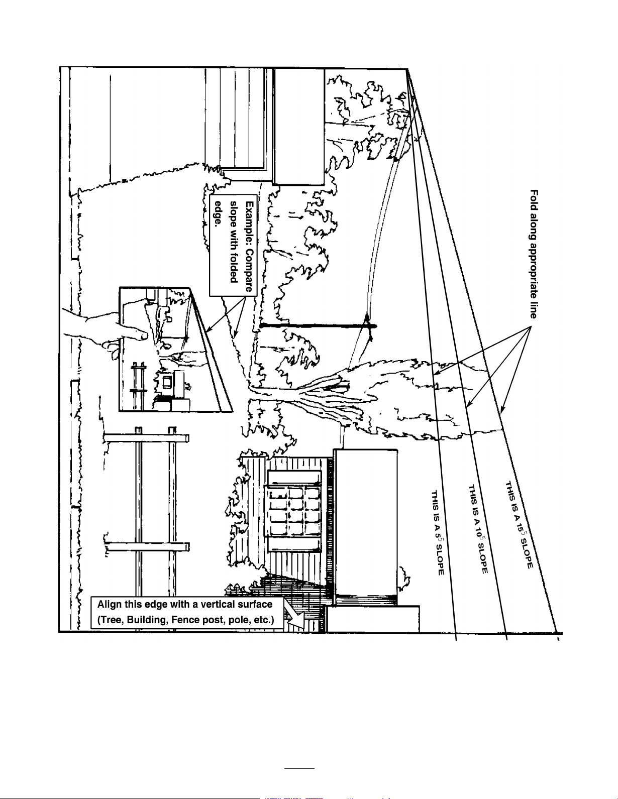
Slope Chart
6

Safety and Instructional Decals
Safety decals and instr uctions are easily visible to the operator and are located near any area of
potential dang er . R e place any decal that is damag ed or lost.
92-6727
1. Fuel levels 2. Fuel
1. Push the lever in to ride on
the machine.
2. Pull the lever out to push
the machine.
92-7090
3. Do not tow the machine
1. Throttle
2. Fast
3. Slow
4. Continuous variable setting
5. Ignition
93-7255
6. Stop
7. Lights
8. Run
9. Start
7
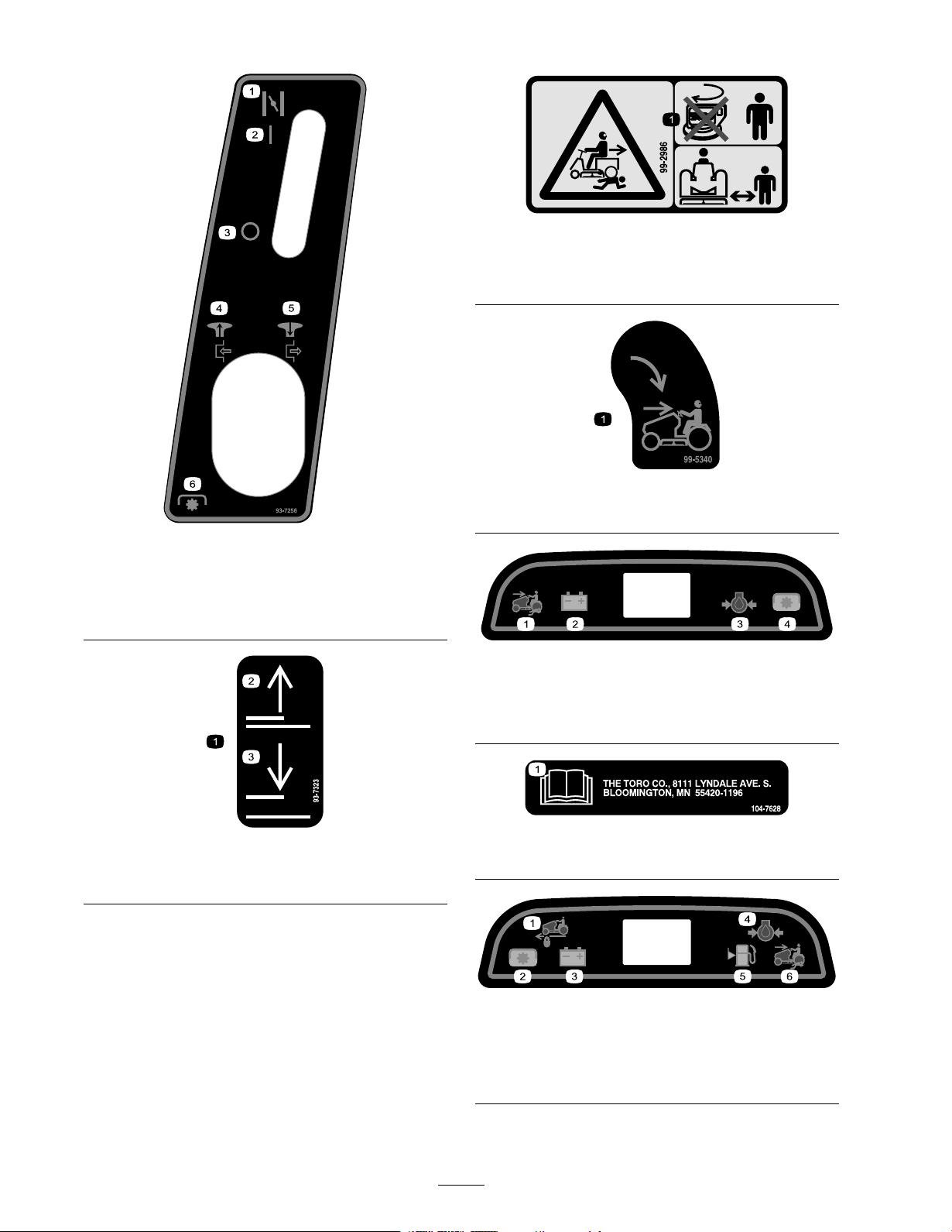
93-7256
1. Choke 4. Pull the knob out to start
2. On
3. Off
PTO.
5. Pull the knob out to stop
PTO.
6. PTO
99-2986
1. Crushing/dismemberment hazard of bystanders—do not
turn the key while children are present; keep children a safe
distance from the machine.
99-5340
1. KeyChoice—turn to enable reverse mowing.
99-8036
Model 420
1. Mowing in reverse enabled. 3. Engine oil pressure
2. Battery
4. Power Take-off (PTO)
104-7628
93-7323
1. Lift
2. Up
3. Down
1. Read the Operator’s Manual.
106-9871
Model 430
1. Cruise control, locked 4. Engine oil pressure
2. Power Take-off (PTO)
3. Battery discharge indicator 6. Mowing in reverse enabled.
5. Fuel level
8

Battery Symbols
Some or all of these symbols are on your battery.
1. Explosion hazard 6. Keep bystanders a safe
2. No re, open ame, or
smoking.
3. Caustic liquid/chemical
burn hazard
4. Wear eye protection
5. Read the Operator’s
Manual.
distance from the battery.
7. Wear eye protection;
explosive gases can cause
blindness and other injuries
8. Battery acid can cause
blindness or severe burns.
9. Flush eyes immediately
with water and get medical
help fast.
10. Contains lead; do not
discard.
1. Warning-read the Operator’s Manual.
2. Tipping hazard—do not drive across
slopes greater than 5 degrees, up slopes
greater than 10 degrees, or down slopes
greater than 15 degrees.
3. Thrown objects hazard—keep
bystanders a safe distance from the
machine.
4. Thrown objects hazard, mower—keep
the deector in place.
93-7313
5. Cutting/dismemberment hazard of
hand or foot, mower blade—stay away
from moving parts.
6. To drive the machine forward, press the
ground speed selector forward.
7. To drive the machine in reverse, press
the ground speed selector rearward.
8. To brake, press the brake pedal.
9
9. To engage the parking brake, press the
beaked pedal and move the parking
brake lever to the On position.
10. To disengage the parking brake, press
and release the brake pedal.

Setup
Loose Parts
Use the chart below to verify that all parts have been shipped.
Step
Steering Wheel
Lock Washer, 1/2 inch
1
2
3
4
5
6
7
Nut, 1/2 inch
Logo Cover
Seat
Spacer, large inside diameter
Spacer, small inside diameter
Shoulder bolt
Knob
Flat washer, 11/32 inch
Bolt, 1/4 x 3/4 inch
Hex Nut, 1/4 inch
Front tires
Cotter pin
Shim washers
Washers, thick
Washers
Cap 2
Rear tires
Lug nuts
No parts required
Operator’s Manual
Engine Operator’s Manual
Parts Catalog
Safety Video
Registration Card
Oil drain hose
Description
Qty.
1
1
Install the steering wheel.
1
1
1
2
2
Install the seat.
2
2
2
2
Activate and install the battery.
2
2
2
4
Install the front tires.
2
2
2
Install the rear tires.
10
Check the Tire Pressure and Tractor
–
Lubrication.
1
1
1
Read the Operator’s Manual and watch
the video before operating the machine.
1
1
1
Use
8
9
Note: Deter mine the left and right sides of the mac hine from the nor mal operating position.
No parts required
No parts required
10
–
–
Check the safety system.
Test drive the tractor.

Step
Step
1
Installing the Steering
Wheel
Parts needed for this step:
1
Steering Wheel
1
Lock Washer, 1/2 inch
1
Nut, 1/2 inch
1
Logo Cover
Procedure
1. P osition the front wheels straight ahead.
2. R emo v e the log o co v er b y releasing the 3 latc hes
from the bac k side with a screw dri v er .
3. Line up the center spok e to w ard the seat and
position the steering wheel onto the shaft spline
( Figure 3 ).
2
Installing the Seat
Parts needed for this step:
1
Seat
2
Spacer, large inside diameter
2
Spacer, small inside diameter
2
Shoulder bolt
2
Knob
2
Flat washer, 11/32 inch
Procedure
1. Install the larg e inside diameter spacer and the
2 shoulder bolts into the rear holes of the seat
( Figure 4 ).
Figure 3
1. Center spoke 4. Nut, 1/2 inch
2. Shaft spline
3. Lock washer, 1/2 inch
4. Secure the steering wheel with a loc kw asher
(1/2 inc h) and n ut (1/2 inc h) ( Figure 3 ).
5. T or que the steering wheel n ut to 50 ft-lb (37 N .m).
6. Snap the log o co v er into place ( Figure 3 ).
5. Logo cover
Figure 4
1. Seat
2. Spacer-small ID 7. Wire harness connector
3. Spacer-large ID 8. Wire clip
4. Shoulder bolt 9. Flat washer, 11/32 inch
5. Knob
2. P osition the seat onto the seat base b y inser ting the
2 shoulder bolts through the k ey hole openings at
the end of both slots ( Figure 4 ).
3. Locate the small inside diameter spacer betw een
the seat and the seat base , thread the 2 knobs and
2 flat w ashers (11/32 inc h) into the front holes in
the seat ( Figure 4 ). Adjust the seat and tighten
the knobs .
11
6. Wire and connector
4. R oute the seat switc h wire and connector through
the center opening in the seat base . Push the
seat switc h connector fully into the wire har ness
connector ( Figure 4 ).
5. Secure the seat switc h wire cable to the fender
opening ( Figure 4 ).
Step
3
Activating and Installing the
Battery
Parts needed for this step:
2
Bolt, 1/4 x 3/4 inch
2
Hex Nut, 1/4 inch
Procedure
Bulk electrolyte with 1.265 specific g ra vity m ust be
purc hased from a local batter y supply outlet.
Batter y electr ol yte contains sulfuric acid which
is a deadl y poison and causes sev er e bur ns.
• Do not drink electr ol yte and a v oid contact
with skin, ey es or clothing . W ear safety
g lasses to shield y our ey es and r ob ber g lo v es
to pr otect y our hands.
• Fill the batter y wher e clean w ater is al w ays
a v aila ble f or flushing the skin.
• F ollo w all instr uctions and compl y with all
safety messa ges on the electr ol yte container .
1. R emo v e the batter y from the tractor .
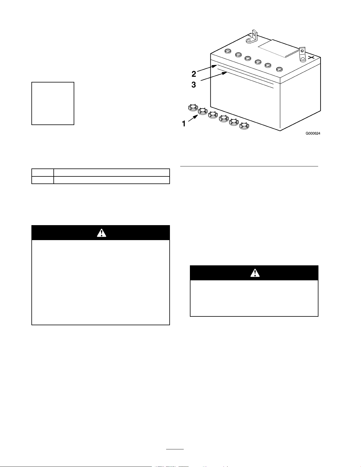
Figure 5
1. Filler caps 3. Lower line
2. Upper line
4. Slo wly pour electrolyte into eac h batter y cell until
the lev el is up to the upper line on the batter y case
( Figure 5 ).
Important: Do not o v erfill the batter y
because electr ol yte (sulfuric acid) can cause
sev er e cor r osion and dama ge to the chassis.
5. W ait fiv e to ten min utes after filling the batter y cells .
Add electrolyte , if necessar y , until the electrolyte
lev el is up to the upper line on the batter y case
( Figure 5 ).
6. Install the batter y filler caps .
Charging the batter y pr oduces gasses that
can explode.
Nev er smok e near the batter y and k eep
spar ks and flames a w ay fr om batter y .
Note: Mak e sure the v ent caps are installed in
the batter y .
2. Clean the top of the batter y with a paper to w el.
Note: Nev er fill the batter y with electrolyte while
the batter y installed in the tractor . Electrolyte could
be spilled on other par ts and cause cor rosion.
3. R emo v e the v ent caps from the batter y ( Figure 5 ).
7. Charg e the batter y for 1 hour at 10 amps or 2 hours
at 5 amps .
8. W hen the batter y is fully c harg ed, unplug the
c harg er from the electrical outlet, then disconnect
the c harg er leads from the batter y posts ( Figure 6 ).
12
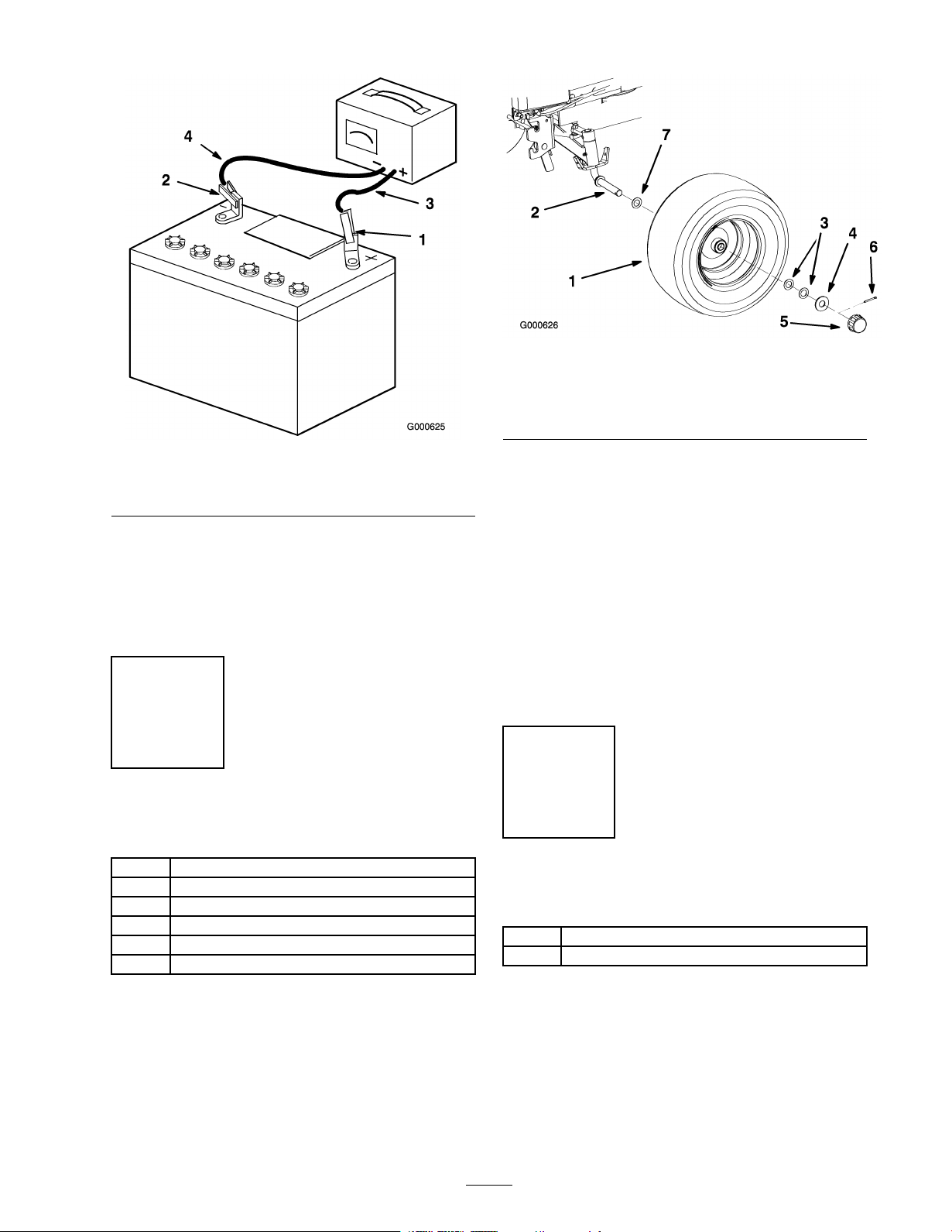
Figure 7
1. Front wheel
2. Axle
3. Shim washer 7. Thin Washer, 3/4 inch
4. Thick washer, 3/4 inch
5. Cap
6. Cotterpin
Figure 6
1. Positive Battery Post
2. Negative Battery Post
9. Install the batter y in the tractor and connect the
batter y cables . R efer to the Installing the Batter y in
Electrical System Maintenance , pag e 32 .
Note: Do not r un the tractor with the batter y
disconnected, electrical damag e ma y occur .
3. Red (+) Charger Lead
4. Black (-) Charger Lead
Step
4
Installing the Front Tires
Parts needed for this step:
2
Front tires
2
Cotter pin
4
Shim washers
2
Washers, thick
2
Washers
2 Cap
3. Slide wheel onto axle with v alv e stem in ( Figure 7 ).
4. W heel end pla y should be 0 to 0.015 inc h
(0 to 0.4 mm). Install the shim w ashers (as
required) and thic k flat w asher (3/4 inc h) for
spacing on the axle .
5. Inser t cotter pin through the axle and bend the
ends of the pin open ( Figure 7 ).
6. Push the cap onto the end of the axle so it snaps
o v er w asher ( Figure 7 ).
7. R e peat ste ps 2 - 6 on opposite side .
8. Grease the wheel bearings .
Step
5
Installing the Rear Wheels
Parts needed for this step:
2
Rear tires
Lug nuts
10
Procedure
1. R emo v e the tires from the crate ( Figure 7 ).
2. Install a thin w asher (3/4 inc h) onto the axle
( Figure 7 ).
Procedure
1. Install the rear wheel onto the wheel hub with the
v alv e stem to the inside ( Figure 8 ).
2. T or que the wheel bolts to 75-80 ft-lb (105-112
N·m).
13
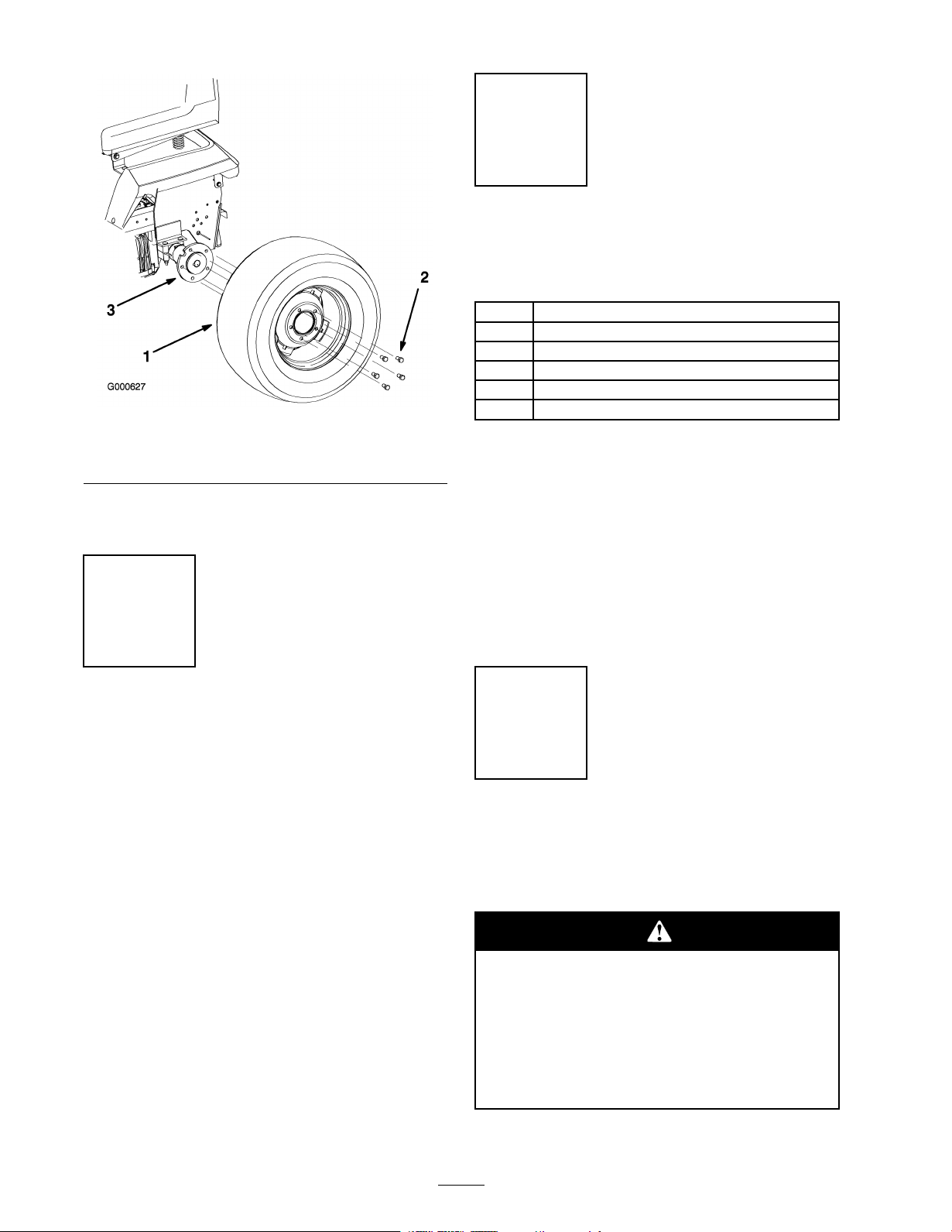
Figure 8
1. Rear wheel 3. Wheel hub
2. Wheel bolts
R efer to Chec king the Safety Interloc k System in
Operation , pag e 19 .
Step
7
Reading the Manual and
Viewing the Safety Video
Parts needed for this step:
1
Operator’s Manual
1
Engine Operator’s Manual
1
Parts Catalog
1
Safety Video
1
Registration Card
1
Oil drain hose
Procedure
• R ead the Operator’ s Man ual.
• Lear n ho w to operate the tractor . R ead the
Operation section in this man ual.
Step
6
Checking the Tire Pressure
and Tractor Lubrication
No Parts Required
Procedure
Chec k the front and rear tire pressure . R efer to
Chec king the Tire Pressure in the Maintenance Section.
Important: T he tractor is shipped fr om the
f actor y with oil in the engine crank case.
Chec k the engine oil and add only enough oil to raise
the lev el to the full mark on the dipstic k. R efer to
Chec king the Engine Oil in the Maintenance Section.
Chec k the tractor to ensure it is lubricated. R efer to
Greasing and Lubrication in the Maintenance Section.
• View the safety video .
• Fill out the registration card.
• Use the oil drain hose when c hanging the engine
oil.
Step
8
Checking the Safety System
No Parts Required
Procedure
If safety inter lock s witches ar e disconnected
or dama ged the machine could operate
unexpectedl y causing per sonal injur y .
• Do not tamper with the inter lock s witches.
• Check the operation of the inter lock s witches
dail y and r eplace an y dama ged s witches
bef or e operating the machine.
14
 Loading...