

Toro 41564, 41020, Multi Pro 5500, 41021 Operator's Manual
FORM NO. 95-9309 Rev A
MODEL NO. 41020-70224 and UP
MODEL NO. 41021-70224 and UP
MODEL NO. 41564-70224 and UP
To assure maximum safety, optimum
performance, and to gain knowledge of the
product, it is essential that you or any other
operator of this vehicle read and understand
the contents of this manual before the engine
is ever started. Pay particular attention to the
SAFETY INSTRUCTIONS highlighted by the
triangular safety alert symbol.
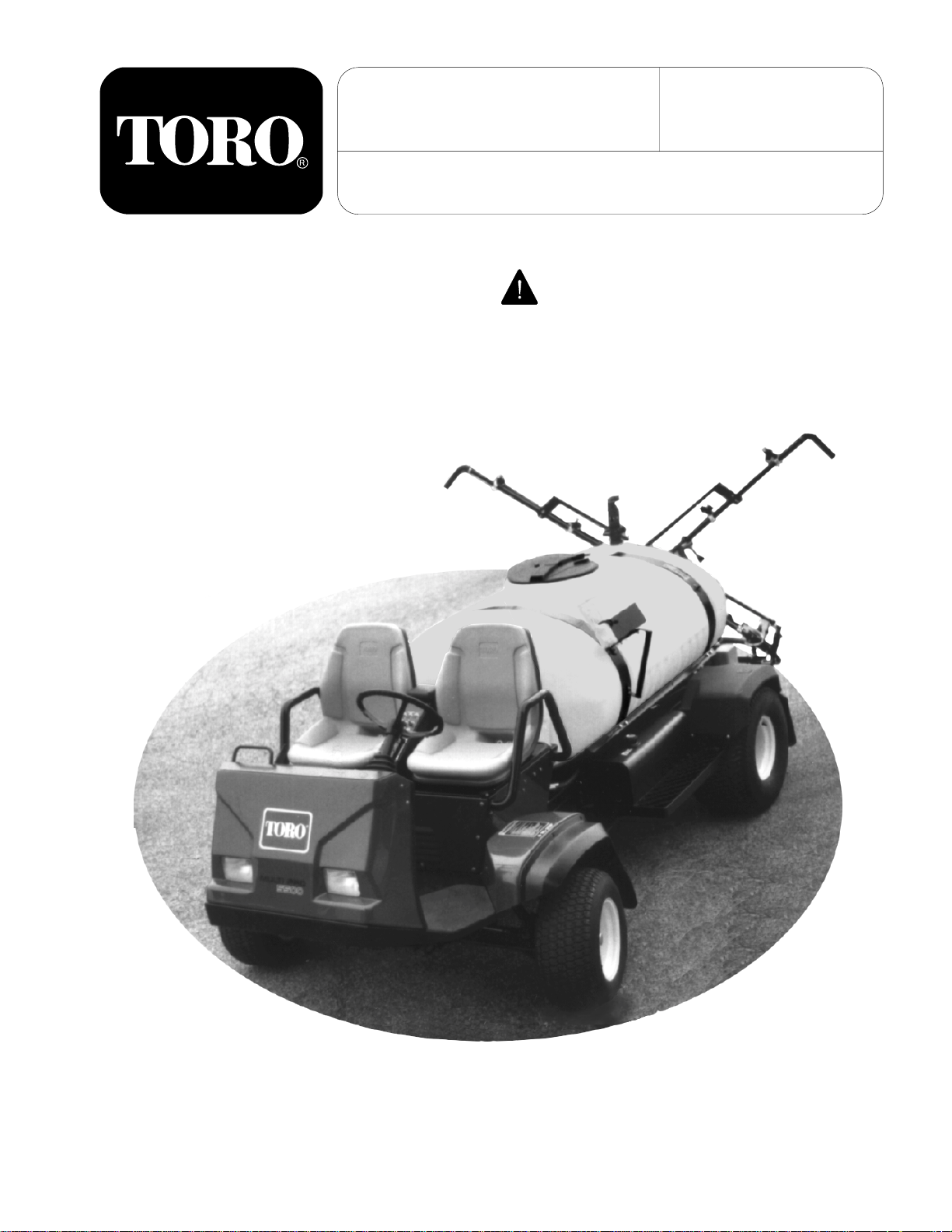
OPERATOR'S &
SET-UP
MANUAL
MULTI PRO® 5500
TURF SPRAYER
The safety alert symbol means CAUTION,
WARNING, or DANGER - personal safety
instruction. Failure to comply with the
instruction may result in personal injury.
©The TORO Company - 1998
All Rights Reserved
1
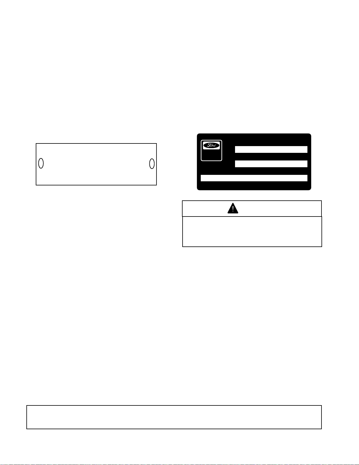
IDENTIFICATION AND ORDERING
VEHICLE:
The MULTI PRO
®
5500 has two identification
numbers: a model number and a serial number.
These numbers are stamped into a plate located
behind the left front fender of the vehicle. In any
correspondence concerning the unit, supply the
model number and serial numbers to ensure
correct information and replacement parts are
obtained. Record your Vehicle Identification
numbers on the illustration below for future
reference.
MOD.
SER.
THE TORO CO.
MINNEAPOLIS, MN. 55420
DATE PURCHASED: _______________________
This vehicle is not a motor vehicle as defined by
the National Traffic Motor Vehicle Safety Act. It is
not designed or manufactured for use on roads,
streets, or highways, and is not to be licensed
as a motor vehicle.
ENGINE:
An Identification Decal is affixed to the right side
of the engine. The decal contains the engine serial
number which identifies this unit from all others.
The model number and S.O.. or special options
determine the parts or components required on
this unit. When ordering parts or in any
communication involving the engine, it will be
necessary to supply the engine manufacturer with
these numbers, to ensure correct information and
replacement parts are obtained. Record the
engine identification numbers on the illustration
below for future reference.
SERIAL NUMBER
Power
Produ c ts
MODEL NUMBER
MODEL CODES.O./OPTIONS
WARNING
The engine exhaust from this product
contains chemicals known to the State
of California to cause cancer, birth
defects, or other reproductive harm.
FOREWORD
You have purchased a vehicle from the industry leader in maintenance excellence. Its future performance
and dependability are of prime importance. TORO is also concerned about future use of the vehicle and
of safety to the user. Therefore, this manual must be read by you and those involved with the MULTI
®
PRO
5500 to assure that safety, proper set-up, operation, and maintenance procedures are followed at
all times. The major sections of the manual are:
1. SAFETY INSTRUCTIONS
4. OPERATING INSTRUCTIONS
Safety, mechanical, and some general information in this manual are emphasized. DANGER, WARNING,
and CAUTION identify safety messages. Whenever the triangle safety symbol appears, it is followed by
a safety message that must be read and understood. For more details concerning safety, read the safety
instructions on pages 4 through 6. IMPORTANT identifies special mechanical information and NOTE
identifies general information worthy of special attention.
OPTIONAL SPARK ARRESTER
In some places a Spark Arrester muffler must be used because of local, state, or federal regulations. The
Spark Arrester available from your local TORO Distributor is approved by the United States Department
of Agriculture and the United States Forest Service.
When the machine is used or operated on any California forest, brush, or grass covered land,
a properly operating Spark Arrester must be obtained and installed to the Muffler. The operator
is violating state law, Section 442 Public Resources Code if a Spark Arrester is not used.
2. SET-UP INSTRUCTIONS
5. MAINTENANCE
3. BEFORE OPERATING
6. SPRAY SYSTEM SECTION
All information, illustrations and specifications in this manual are based on the latest product information available at the time of
publication. The right is reserved to make any changes at any time without notice.
2

TABLE OF CONTENTS
SAFETY INSTRUCTIONS .................................................................................................... 4-6
SPECIFICATIONS ...................................................................................................................7
SAFETY AND INSTRUCTION DECALS ............................................................................... 8,9
SET-UP INSTRUCTIONS
BATTERY SERVICE ........................................................................................................ 10
SPRAY SYSTEM......................................................................................................... 11-14
FRESH WATER TANK ..................................................................................................... 14
BEFORE OPERATING ...................................................................................................... 15-19
VEHICLE CONTROLS ......................................................................................................20,21
OPERATING INSTRUCTIONS.......................................................................................... 22-26
MAINTENANCE ................................................................................................................26-44
DAILY MAINTENANCE SCHEDULE................................................................................ 27
MAINTENANCE SCHEDULE .......................................................................................... 28
JACKING VEHICLE ......................................................................................................... 29
LUBRICATION ................................................................................................................. 30
AIR CLEANER MAINTENANCE ...................................................................................... 31
ENGINE MAINTENANCE ........................................................................................... 32-33
COOLING SYSTEM MAINTENANCE.............................................................................. 34
BELT MAINTENANCE ..................................................................................................... 35
HYDRAULIC SYSTEM MAINTENANCE .......................................................................... 36
HYDRAULIC SYSTEM DIAGRAM ................................................................................... 37
HYDRAULIC SYSTEM ..................................................................................................... 38
BRAKE MAINTENANCE .................................................................................................. 39
THROTTLE LEVER TENSION ......................................................................................... 39
AXLE MAINTENANCE ..................................................................................................... 40
ELECTRICAL MAINTENANCE ........................................................................................ 41
VEHICLE ELECTRICAL DIAGRAM ................................................................................. 42
TRACTION DRIVE MAINTENANCE ........................................................................... 43-44
SPRAY SYSTEM
SPRAYING SYSTEM ..............................................................................................................45
CONTROLS AND OPERATION ............................................................................................. 46
BEFORE SPRAYING
NOZZLE SELECTION GPA/GAL/1000 FT2................................................................ 46,47
NOZZLE SELECTION LIT/HA ......................................................................................... 48
DEFINITIONS/CONVERSIONS ....................................................................................... 49
FRESH WATER WASH TANK ......................................................................................... 50
SYSTEM SET-UP............................................................................................................. 51
FILLING SOLUTION TANK.............................................................................................. 51
OPERATION
USING THE SPRAYER............................................................................................... 51,52
AFTER SPRAYING .......................................................................................................... 52
PREVENTATIVE MAINTENANCE ......................................................................................... 52
PUMP MAINTENANCE......................................................................................................... 53
MAINTENANCE
TROUBLESHOOTING SOLENOID VALVE...................................................................... 54
SOLENOID VALVE MAINTENANCE .......................................................................... 55,56
FLOW DIAGRAM .................................................................................................................. 57
SPRAY SYSTEM ELECTRICAL DIAGRAM .......................................................................... 58
STORAGE ............................................................................................................................. 59
PERFORMANCE VERIFICATION................................................................................... 60, 61
TORO PROMISE................................................................................................................... 64
3

SAFETY INSTRUCTIONS
The MULTI PRO
®
5500 Turf Sprayer was
designed and tested to offer safe service when
operated and maintained properly. Although
hazard control and accident prevention partially
are dependent upon the design and
configuration of the vehicle, these factors are
also dependent upon the awareness, concern,
and proper training of the personnel involved
in the operation, maintenance, and storage of
the vehicle. Improper use or maintenance of
the vehicle can result in injury or death.
This is a specialized Turf Sprayer designed for
off road use. Its ride and handling will have a
different feel than what drivers experience with
passenger cars or trucks. So take time to
become familiar with your MULTI PRO
®
5500.
The attachments that adapt to the MULTI PRO
5500 are not covered in this manual. See the
specific Operator's Manual provided with the
attachment for additional safety instructions.
READ THESE MANUALS.
TO REDUCE THE POTENTIAL FOR INJURY OR
DEATH, COMPLY WITH THE FOLLOWING
SAFETY INSTRUCTIONS:
SUPERVISOR'S RESPONSIBILITIES
1. Make sure operators are thoroughly trained
and familiar with the Operator's Manual and all
labels on the vehicle.
2. Be sure to establish your own special
procedures and work rules for unusual operating
conditions (e.g. slopes too steep for vehicle
operation).
BEFORE OPERATING
3. Operate the vehicle only after reading and
understanding the contents of this manual. A
replacement manual is available by sending
complete model and serial number to: Hahn
Equipment Co., A subsidiary of The Toro
Company, 1625 N. Garvin, Evansville, Indiana
47711-4596.
5. This vehicle is designed to carry One
Operator, and One Passenger. Never carry more
than one passenger on the vehicle.
6. Never operate the vehicle when under the
influence of drugs or alcohol.
7. Become familiar with the controls and know
how to stop the engine quickly.
8. Keep all shields, safety devices, and decals
in place. If a shield, safety device, or decal is
malfunctioning, illegible, or damaged, repair or
replace it before operating the vehicle.
9. Always wear substantial shoes. Do not
operate vehicle while wearing sandals, tennis
®
shoes, or sneakers. Do not wear loose fitting
clothing or jewelry which could get caught in
moving parts and cause personal injury.
10. Wearing safety glasses, safety shoes, long
pants, and a helmet is advisable and required by
some local safety and insurance regulations.
11. Keep everyone, especially children and pets,
away from the areas of operation.
12. Before operating the vehicle, always check
all parts of the vehicle and any attachments. If
something is wrong, stop using the vehicle.
Make sure the problem is corrected before vehicle
or attachment is operated again.
13. Since gasoline is highly flammable, handle it
carefully.
A. Use an approved gasoline container.
B. Do not remove cap from fuel tank when
engine is hot or running.
C. Do not smoke while handling gasoline.
D. Fill fuel tank outdoors and to
approximately one inch below top of tank,
(bottom of filler neck). Do not overfill.
Read and understand the Engine Manufacturer's
Operator's Manual. Follow the safety alert
messages.
4. Never allow children to operate the vehicle
or adults to operate it without proper instructions.
Only trained and authorized persons should
operate this vehicle. Anyone who operates the
vehicle should have a motor vehicle license.
4
E. Wipe up any spilled gasoline.
14. The MULTI PRO
®
5500 is equipped with a
Neutral Lock-Out Switch. The purpose of this
switch is to insure that the vehicle will not start
unless the Traction Pedal is in the NEUTRAL
position. Should the vehicle start when the
Traction Pedal is not in the NEUTRAL position,
shut off the engine and refer to the Traction Drive
Maintenance instructions on pages 43 and 44.

SAFETY INSTRUCTIONS
WHILE OPERATING
WARNING: Do not run engine in a confined
area without adequate ventilation. Exhaust
fumes are hazardous and could possibly be
deadly.
15. Operator and passenger should remain
seated whenever the vehicle is in motion. Operator
should keep both hands on steering wheel
whenever possible, and passenger should use
hand holds provided. Keep arms and legs within
the vehicle body at all times. Remember your
passenger may not be expecting you to brake or
turn and may not be ready.
16. Sit on seat when starting and operating the
vehicle.
17. When starting the engine:
A. Engage the Parking Brake.
B. Make sure Traction Pedal is in
NEUTRAL. Move the Throttle Lever to 1/4
to 1/3 throttle.
whenever possible. Reduce speed when
making sharp turns or when turning on
hillsides.
D. If engine stalls or loses power and
cannot make it to the top of a slope, do not
turn vehicle around. Always back slowly
straight down the slope.
E. Use extra caution when operating
vehicle on wet surfaces, at higher speeds
or with a full load. Stopping time will
increase with a full load.
F. Operate vehicle with extra caution
when handling off-center loads that cannot
be centered.
G. Avoid sudden starts and stops. Do not
go from reverse to forward or forward to
reverse without first coming to a complete
stop.
H. Do not attempt sharp turns or abrupt
maneuvers or other unsafe driving actions
that may cause a loss of vehicle control.
C. After engine is started, release parking
brake and keep foot off traction pedal. The
vehicle must not move. If movement is
evident, the neutral return mechanism is
adjusted incorrectly. Shut engine off and
refer to the Traction Drive Maintenance
section on pages 43 and 44.
18. Operator and passenger must be skilled and
trained in how to drive on hillsides. Failure to use
caution on slopes or hills may cause loss of control
and vehicle to tip or roll, possibly resulting in
personal injury or death.
19. Using the vehicle demands attention. Failure
to operate vehicle safely may result in an accident,
tip over of vehicle and serious injury or death.
Drive carefully. To prevent tipping or loss of
control:
A. Use extreme caution, reduce speed
and maintain a safe distance around sand
traps, ditches, creeks, ramps, and any
unfamiliar areas, or other hazards.
B. Watch for holes or other hidden
hazards.
I. Before backing up, be sure no one is
behind the vehicle. Back up slowly.
J. Watch out for traffic when near or
crossing roads. Always yield the right of
way to pedestrians and other vehicles. This
vehicle is not designed for use on streets
or highways. Always signal your turns and
stop early enough to let other people know
what you plan to do. Obey all traffic rules
and regulations.
K. Never operate vehicle in or near an
area where dust or fumes which are
explosive, are in the air. The electrical and
exhaust systems of the vehicle can produce
sparks capable of igniting explosive
materials.
L. Watch out for and avoid low overhangs
such as tree limbs, door jambs, overhead
walkways, etc. Make sure there is enough
room overhead to easily clear the vehicle
and your head.
M. If ever unsure about safe operation,
STOP WORK and ask your supervisor.
C. Always reduce speed before starting
up or down a hill. Do not start or stop
suddenly when traveling uphill or downhill.
Use caution when operating vehicle on a
steep slope. Normally travel straight up and
down slopes. Avoid turning on hillsides
5

SAFETY AND INSTRUCTIONS
20. Do not touch Engine, Muffler, or Muffler Shield
while engine is running or soon after it has stopped
because these areas may be hot enough to cause
burns.
21. If the vehicle ever vibrates abnormally, stop
immediately, turn off engine, wait for all motion to
stop, and inspect for damage. Repair all damage
before commencing operation.
22. Before getting off the seat:
A. Remove foot from Traction Pedal,
stopping movement of the vehicle.
B. Set Parking Brake.
C. Shut engine off.
D. Remove Key from Ignition Switch.
E. Do not park on slopes unless wheels
are chocked or blocked.
MAINTENANCE
23. Before servicing, lubricating or making
adjustments to the vehicle, stop engine, set
Parking Brake and remove Key from Ignition
Switch to prevent accidental starting of the engine.
24. Make sure the vehicle is in safe operating
condition, keeping all nuts, bolts, and screws tight.
25. To reduce potential fire hazard, keep the
engine area free of excessive grease, grass,
leaves, and accumulation of dirt. Do not wash a
warm engine or electrical components.
26. Make sure all hydraulic line connectors are
tight, and all hydraulic hoses and lines are in good
condition before applying pressure to the system.
27. Keep body and hands away from pin hole
leaks in hydraulic lines that eject high pressure
hydraulic fluid. Use cardboard or paper to find
hydraulic leaks. Hydraulic fluid escaping under
pressure can penetrate skin and cause injury.
Fluid accidentally injected into the skin must be
surgically removed within a few hours by a doctor
familiar with this form of injury, or gangrene may
result.
28. Before disconnecting or performing any work
on the hydraulic system, all pressure in the system
must be relieved by stopping the engine.
29. If major repairs are ever needed or assistance
is required, contact an Authorized TORO
Distributor.
30. Disconnect battery before servicing the
vehicle. If battery voltage is required for
troubleshooting, temporarily connect the battery.
31. If the engine must be running to perform
maintenance, or an adjustment, keep hands, feet,
clothing, and any parts of the body away from the
engine and any moving parts. Keep everyone
away.
32. Do not over-speed engine by changing
Governor settings. Maximum engine speed is
3200 no-load rpm. To assure safety and accuracy,
have an Authorized TORO Distributor check
maximum engine speed with a tachometer.
33. Shut engine off before checking or adding oil
to the crankcase.
34. To assure optimum performance and
continued safety of the vehicle, always use
genuine TORO replacement parts and
accessories. Replacement parts and accessories
made by other manufacturers could be
dangerous. Altering this vehicle in any manner
may affect the vehicle's operation, performance,
durability, or its use may result in injury or death.
Such use could also void the product warranty of
the TORO Company.
35. This vehicle should not be modified without
The Toro Company's authorization. Direct any
inquiries to:
Hahn Equipment Co.
A subsidiary of The Toro Company
1625 N. Garvin Street
Evansville, IN 47711-4596
6

SPECIFICATIONS
Vehicle: Four-wheel step through, out front
operator style, two person vehicle.
Engine: Ford, 4 cycle, 4 cylinder, overhead valve,
liquid cooled gas engine with centrifugal water
pump. Ford rates engine at 45 HP. Mechanically
governed to a maximum speed of 3200
79 cu. in. (1300 cc) displacement. Distributorless
electronic ignition. 3.5 quart (3.25 liter) oil
capacity; replacement oil filter. Forged connecting
rods, cast iron cylinder head and block.
Mechanical fuel pump.
Air Cleaner: Heavy duty, 2 stage, remote
mounted.
Battery: 12 volt with 420 cold cranking amps at
0° F.
Cooling System: Mid mounted radiator with oil
cooler mounted in front of radiator. Cooling
system capacity is 12 quarts (11.5 liters) of 50/50
mixture of ethylene glycol anti-freeze.
Fuel System: Capacity is approximately 10.6
gallon (40 liters) of lead-free gasoline.
+ 100 rpm.
Controls: Foot operated traction pedal, brake,
brake lock pedals, and remote boom on/off switch.
Hand operated throttle, speed control, choke
control, ignition switch, light switch, pressure
increase/decrease, master boom on/off, hydraulic
spray pump, agitator, and individual boom on/off
switches.
Gauges: Sprayer pressure gauge, engine oil
pressure warning light, temperature gauge,
voltmeter, and hour meter.
Lights: Twin halogen headlights.
Ground Speed: Working 2 - 6 mph
Transporting 0 - 11.5 mph
Reverse 0 - 4 mph
Sprayer Tank: 300 gallon capacity.
Spray Pump: Closed impeller hydraulic driven
centrifugal. Adjustable hydraulic drive. 120 gpm
(454 lpm), 100 psi (690 kpa) maximums.
Boom Assembly: Three section, 18.5 foot (5.6
meter) working width.
Traction System: Servo-controlled hydrostatic
system driving double planetary gear reduction
rear wheel drives. Foot pedal control of forward/
reverse ground speed.
Frame: Welded, high strength steel tubing.
Front Suspension: Straight axle with twin
independent leaf springs, dual shock absorbers.
Rear Suspension: Rigid frame.
Tires: Front: 23 x 10.5 x 12, 4-ply rating, turf tread.
Rear: 26.5 x 14 x 12, 4-ply rating, turf tread.
Brakes: Individual totally enclosed, multi-disc, wet
brakes and parking brakes on rear traction wheels.
Hydrostatic braking through traction drive.
Steering: Full hydraulic power with dedicated
power source.
Seats: Twin molded cushions and back rests, with
hip restraints.
Electrical Features: 12 volt, 420 cold cranking
amperes at 0° F, maintenance free battery. 51 amp
alternator with I/C regulator. Automotive type
electrical system. Traction interlock switch.
Nozzles: Drift reduction, quick disconnect with
diaphragm check valves.
General Specifications (approx.):
Base Weight: Base unit 1,750 lbs.
With standard spray sys.
and operator: dry 2,540 lbs.
full 5,040 lbs.
Maximum Gross Vehicle Weight: 6,040 lbs.
Measurements with spray system:
Overall Width: 72"
Overall Length: 136"
Height: 57-1/2"
Ground Clearance: 6-1/2"
Wheel Base: 78"
7
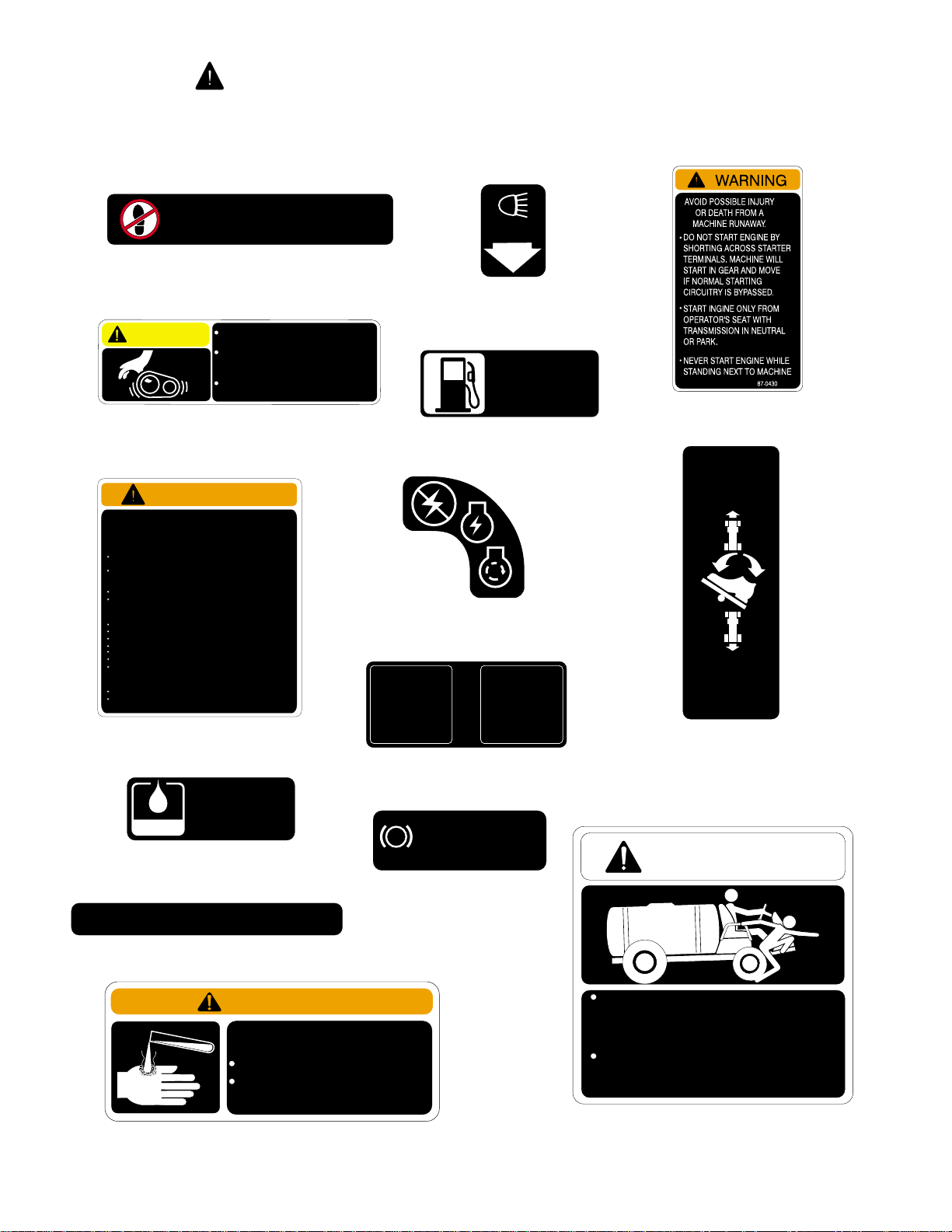
SAFETY AND INSTRUCTION DECALS
The following safety and instruction decals are installed on the vehicle. If any become damaged
or illegible, replace them. Decal part numbers are listed below and in the parts catalog. Order
replacements from your Authorized TORO Distributor.
94-7171
NO STEP
Part No. 36-3400: One Located on
right Front Fender, One on left Front
Fender.
CAUTION
Part No. 87-0450: Located on left side
WARNING
FAILURETO OBEY THE SAFETY WARNINGS MAY RESULT IN
INJURY TO YOU OR OTHERS.
THIS VEHICLE IS OF SUFFICIENT SIZE AND WEIGHT TO CAUSE
SERIOUS INJURY IN CASE OF UPSET OR COLLISION.
BEFORE OPERATING VEHICLE:
READ AND UNDERSTAND OPERATOR’S MANUAL LOCATED
BEHIND SEAT.
DO NOT EXCEED PAYLOAD CAPACITY OF VEHICLE AND/OR
TORO ACCESSORIES OR PERMIT PASSEGER ANY PLACE ON
VEHICLE EXCEPTSEAT.
USE HAND HOLDS WHERE APPLICABLE.
PLACE HEAVYLOADS FORWARD OF REAR AXLE.UNBALANCED
OR TOP HEAVYLOADS CAN CAUSE UPSET.
BEFORE OPERATING VEHICLE:
REMAIN SEATED AND USE BOTHHANDS FOR STEERING.
KEEP ARMS AND LEGS WITHIN VEHICLE BODY.
AVOID SUDDEN STARTS AND STOPS
SUDDEN SHARP TURNS CAN CAUSE UPSET.
REGULATE SPEED TO MEET ROAD AND WEATHER CONDITIONS.
DO NOT OPERATE IN OR NEAR AN EXPLOSIVE ENVIRONMENT.
IF A MALFUNCTION OCCURS, CEASE OPERATION. DO NOT
OPERATE VEHICLE UNTIL CONDITION IS CORRECTED.
BEFORE LEAVINGVEHICLE:
TURN IGNITION TO "OFF" POSITION, REMOVEKEY.
APPLY PARKING BRAKE; PARKING BRAKE IS NOT
AUTOMATICALLY APPLIED.
Part No. 87-0580: Located on Left
Front Fender.
Part No. 85-4730: Located on top of
Hydraulic Tank.
BOOM SECTION
BOOM 1 BOOM 2 BOOM 3
Part No. 94-7173: Located on Dash
Panel, above Indicator Lights.
TO AVOID PERSONAL INJURY KEEP
ALL SHIELDS IN PLACE.
DISENGAGE AND SHUT OFF
ENGINE BEFORE SERVICING OR
UNCLOGGING MACHINE.
KEEP HANDS, FEET AND CLOTHING
AWAY FROM POWER-DRIVEN PARTS.
of Center Console.
87-0580
HYDRAULIC
OIL ONLY
USE MOBIL 424
85-4730
94-7173
36-3400
87-0450
Part No. 71-3730: Located on
Part No. 87-0500: Located on Dash
Panel, above Key Switch.
MASTER
BOOM
ON/OFF
Part No. 94-7132: Located on Floor
Board, left of Brake Lock Pedal.
PARKING BRAKE
1. DEPRESS BRAKE PEDAL
P
2. DEPRESS PARKING
BRAKE LOCK
Part No. 94-7172: Located
on left side of Dash Panel,
under Steering Wheel.
LIGHTS
Part No. 94-7171:
Located on Dash Panel,
right of Light Switch.
GAS
ONLY
top of Gasoline Tank.
PARKING
BRAKE
94-7132
LOCK
94-7172
71-3730
Part No. 87-0430: Located behind Left
Front Fender.
TRACTION
PEDAL
FORWARD
92-0479
REVERSE
VEHICLE SPEED
INCREASES
WITH MORE PEDAL
PRESSURE
Part No. 92-0479: Located on
Floorboard, right of Traction Pedal.
WARNING
LEAVING SEAT WHILE VEHICLE IS
IN MOTION COULD RESULT IN SERIOUS
INJURY OR DEATH.
ALWAYS ALLOW VEHICLE TO COME
TO A COMPLETE STOP BEFORE
EXITING OR BOARDING VEHICLE.
Part No. 95-2136: Located on
the right end of the Dash.
95-2136
93-0688
WARNING
CHEMICALS CAN BE HAZARDOUS
TO REDUCE THE RISK OF ENVIRONMENTAL
DAMAGE AND PERSONAL INJURY
SELECT THE CORRECT CHEMICAL FOR THE
APPLICATION.
HANDLE AND APPLY CHEMICALS AS
INSTRUCTED BY THE CHEMICL
MANUFACTURER’S LABELS. ALWAYS
WEAR PROTECTIVE CLOTHING AND MASK.
Part No. 93-0688: Located on
Spray Tank Lid.
8

SAFETY AND INSTRUCTION DECALS
The following safety and instruction decals are installed on the vehicle. If any become damaged
or illegible, replace them. Decal part numbers are listed below and in the parts catalog. Order
replacements from your Authorized TORO Distributor.
Part No. 62-5550: Located on Front of
Front Console.
READ YOUR OPERATOR’S MANUAL FOR OPERATING AND
SAFETY INSTRUCTIONS. TO GET A REPLACEMENT MANUAL,
SEND MODEL AND SERIAL NUMBERS TO : THE TORO CO., 8111
LYNDALE AVE. S., MPLS., MN 55420
Part No. 65-3090: Located on left side
of Dash Panel.
SPEED CONTROL
WARNING
IMPROPER USE OF
SPEED CONTROL
COULD RESULT IN
PERSONAL INJURY.
SEE OPERATOR’S
MANUAL PRIOR TO
OPERATION.
ON
OFF
94-7175
VEHICLE LOAD AND TURF
CONDITIONS AFFECT BRAKE
PERFORMANCE. FAILURE TO
OPERATE VEHICLE PROPERLY
COULD RESULT IN PERSONAL
INJURY.
AVOID HIGH SPEEDS OR ABRUPT
STOPS ON SLOPES AND WET
TURF.
SEE OPERATOR’S MANUAL
FOR ADDITIONAL INFORMATION.
65-3090
WARNING
94-7176
ON
L
T
H
OFF
FOAM MARKER
R
O
T
T
L
E
ON
OFF
MASTER
BOOM
ON
OFF
BOOM 1 BOOM 2 BOOM 3
ON
DOWN DOWN
L
UP UP
BOOM LIFT
LOWER
RAISE
PRESSURE
(DUMP BED)
ON
OFF
PUMP
ON
OFF
ON
ON
R
OFF
R
AUTO
OFF
(SET)
MAN
SONIC
BOOM
ON
OFF
AGITATOR
ON
OFF
ON
SET
Part No. 94-7175: Located on Dash
Panel, right of Steering Wheel.
CAUTION
Part No. 42958: Located on
left radiator brace.
CAUTION
Part No. 87-0570: Located on Rear
Tank Band.
TO AVOID ELECTRIC SHOCK
AND PERSONAL INJURY TO
INSPECT AREA OVERHEAD FOR
WIRES BFORE RAISING BOOMS.
KEEP BYSTANDERS AWAY WHILE
RAISING AND LOWERING BOOMS.
Part No. 94-7176: Located
on Dash panel, under grab bar.
BYSTANDERS
87-0570
OFF
AGITATOR
CHEM 1
OFF
RINSE
PUMP
InJector Pro™
OFF
AGITATOR
CHEM 2
94-7134
Part No. 94-7134: Located on the Center
Console.
Part No. 94-7133: Located on
Front of Front Console.
9
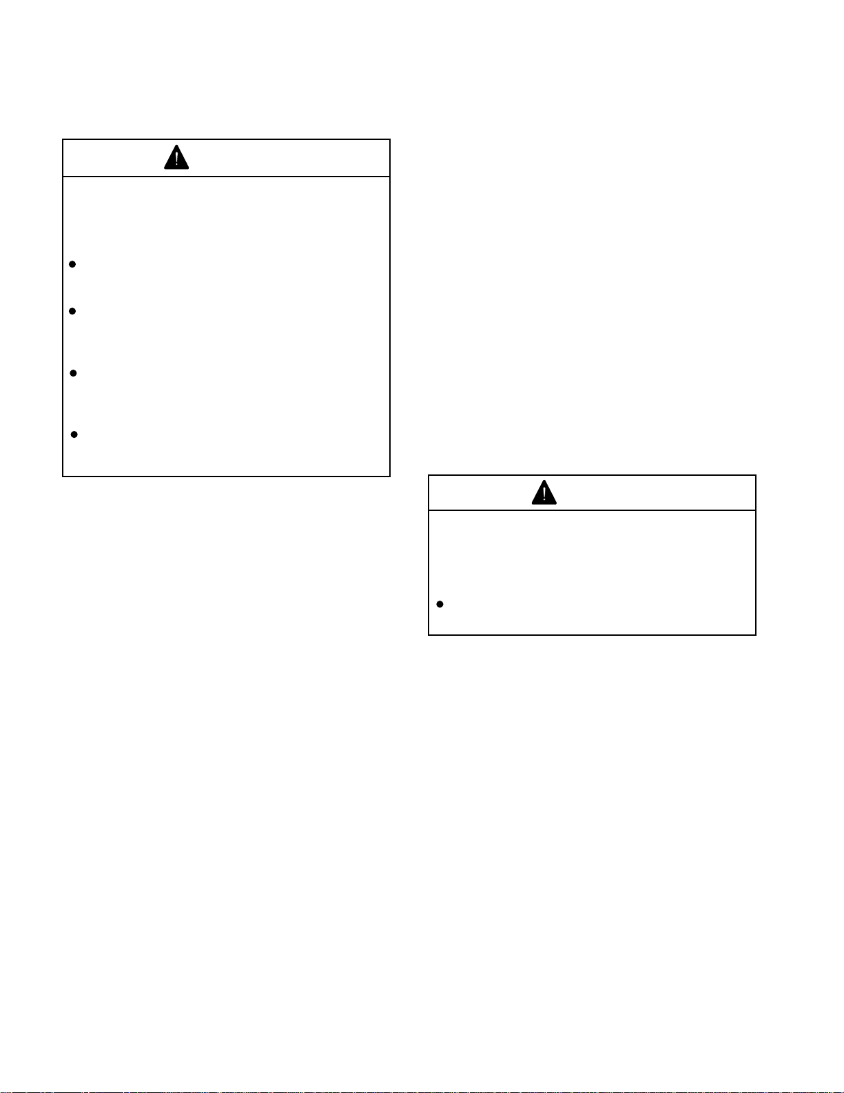
SET-UP INSTRUCTIONS
BATTERY SERVICE:
CAUTION
Electrolyte gases are explosive and can
cause serious injury to eyes, lungs, and
skin. Nausea may result if the gases are
inhaled.
Wear safety goggles and rubber gloves
when working with electrolyte or battery.
Charge the Battery in a well ventilated
place so gases produced while charging
can dissipate.
Unplug charger from electrical outlet
before connecting to or disconnecting
charger leads from battery posts.
Since the gases are explosive, keep open
flames and electrical spark away from the
battery; DO NOT SMOKE!
The Battery has been filled with electrolyte and
charged at the factory. However, prior to actual
operation, it may be necessary to bring the Battery
to a full charge as follows:
1. First disconnect the black negative (-) cable,
then disconnect the red positive (+) cable.
2. Connect a 3 to 4 amp battery charger to the
Battery Posts. Charge the Battery at a rate of 3 to
4 amperes for 4 to 8 hours.
3. When Battery is charged, disconnect the
charger from electrical outlet and battery posts.
IMPORTANT! If optional electric powered
equipment is to be installed on the MULTI PRO
5500, DO NOT connect the battery cables until
all wiring harness connections for the optional
equipment have been completed. If
accidentally grounded, the lead to the battery
terminal will burn the accessory's wiring
harness. After the accessory's wiring harness
has been connected, proceed as follows:
4. Connect the red positive (+) cable to the
positive (+) post on the battery first, then connect
the black negative (-) cable to the negative (-)
post on the battery. Secure with cap screws and
nuts. Slide the rubber boot over the positive
terminal to prevent short-out from occurring.
WARNING
Connecting cables to the wrong post
could cause the battery to explode,
resulting in personal injury and damage
to the electrical system.
Make sure Battery Cables do not interfere
or rub on any moving or hot parts.
®
10
SET-UP INSTRUCTIONS
CAUTION
Chemicals are hazardous and can cause
personal injury!
Securely tighten all sprayer hose clamp
connections during initial set-up to
prevent leaks and hose blow-offs while
spraying system is in operation.
SPRAY SYSTEM:
NOTE: In the following instructions, "sealer"
refers to the Teflon Thread Tape.
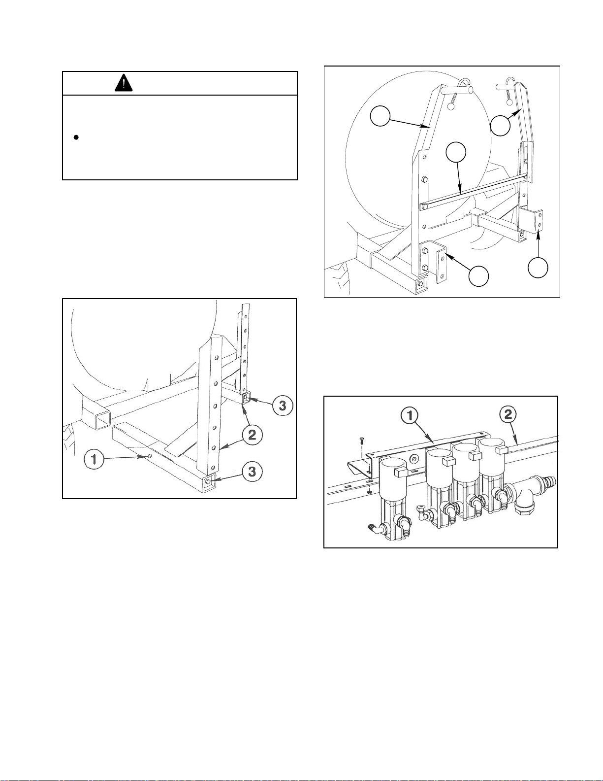
1. Apply a heavy coating of grease to the tubes
of the two Boom Mount Assemblies and insert
them into the Vehicle Frame until Stop Pin bottoms
out against Vehicle Frame. (See FIG. 1.)
1
1
2
3
3
1140
Figure 2
1. Boom Hold-In Ass'y. 3. Boom Mounting
2. Angle Crossmember Bracket
1139-1
Figure 1
1. Stop Pin 3. 1/2" x 18" screws
2. Boom Mount Ass'y.
2. Using a torque wrench, tighten the 1/2" x 18"
screws that join the Wedges to the Boom Mounts.
Tighten to 50 ft. lbs.
NOTE: If installing the "Enclosed Boom" option
in place of the Standard Boom, DO NOT install
the (2) Boom Hold-In Assemblies in Step 3 or
the (2) Boom Mounting Brackets in Step 4.
.
3. Install the two (2) Boom Hold-In Assemblies
and the Angle Crossmember to the top of the
Boom Mount uprights as shown in FIG. 2, using
four (4) 1/2" x 1-1/4" cap screws, flat washers and
lock nuts.
5. Attach the Solenoid Assembly to the Angle
Crossmember with four (4) 5/16" hex head cap
screws and hex nuts. (See FIG. 3.)
1015
Figure 3
1. Solenoid Ass'y 2. Angle Crossmember
NOTE: If installing the "Enclosed Boom" option
in place of the Standard Boom, skip steps 6-19.
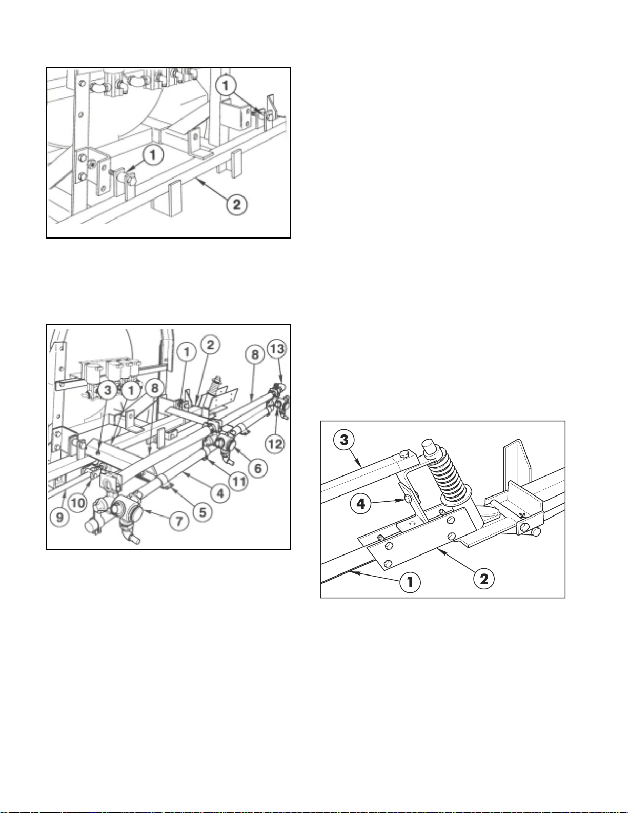
6. Position a Spacer Tube between the lugs on
each side of the Main Frame tube. Insert a 1/2" x
2-1/2" cap screw through the lugs and spacers.
Secure the Main Frame to the Boom Mounting
Brackets with lock nuts. (See FIG. 4.)
4. Attach the two "U"-shaped Boom Mounting
Brackets to the bottom of the Boom Mount
uprights with four (4) 1/2" x 1-1/4" cap screws, and
lock nuts. (See FIG. 2.)
11
SET-UP INSTRUCTIONS
1141
Figure 4
1. Spacer Tube 2. Main Frame
10. Loosely attach a Single Barb Turret Body with
the Turret Body Clamp to LH end of the Center
Boom Pipe. Loosely attach a threaded Turret Body
with the Turret Body Clamp to RH end of the Center
Boom Pipe.
11. Place two Hose Clamps on two 3/4" x 19"
Jumper Hoses and connect the two "end" Turret
Bodies to the Double Barb Turret Body. Space
nozzles 20" apart and tighten fasteners securely.
Apply thread sealer and install the 90° 3/4" Hose
Barb on the Threaded Turret Body. (See FIG. 5.)
12. Attach the two Strut Assemblies to the two
adjustable clevis' found on each side of the Main
Frame tube with two (2) 1/2" x 2" clevis pins and
two (2) 1/8" x 1" cotter pins. (See FIG. 5)
7. Position the two (2) Center Boom angles on
the Main Frame and secure them to the Main
Frame tube with two (2) square U-bolts, four (4)
flat washers and hex nuts. (See FIG. 5.)
1016
Figure 5
1. Center Boom Angle 8. Jumper Hose
2. Main Frame 9. Strut Assembly
3. U-bolt 10. Adjustable Clevis
4. Center Boom Pipe 11. Turret Body Clamp
5. Boom Clamp 12. Threaded Barb Turret
6. Double Barb Turret 13. 90° Hose Barb
7. Single Barb Turret
8. Center and attach the Center Boom Pipe to
the two Center Boom Angles with two (2) clamps,
(2) 3/8" x 1" cap screws, flat washers and lock nuts.
Once mounted the Center Boom Pipe should be
approx. 20" from ground.
9. Loosely attach the Double Barb Turret Body
with the Turret Body Clamp in the approximate
center of the Center Boom Pipe. For the most
uniform spray coverage, position all Nozzles level
as shown in FIG. 5.
NOTE: If the optional "Foam Marker Kit" is to
be installed, refer to the instructions furnished
with that kit before proceeding to step 13.
IMPORTANT! DO NOT over-tighten the nuts in
steps 13 and 15. The clamping action could
crush the Boom Pipe.
13. Insert the plugged end of an Extension Boom
Pipe into the Pivot Assembly and secure with four
(4) 1/4" x 1-1/4" cap screws and lock nuts. (See
FIG. 6) Repeat on the opposite side to assemble
the other Extension Boom.
Figure 6
1. Extension Boom Pipe 3. Boom Support
2. Pivot Assembly Assembly
4. Height Adjustment
14. Attach the LH Boom Support Assembly to the
Pivot Assembly, using a 5/16" x 1-1/2" cap screw
and lock nut. (See FIG. 6 & 7.)
15. Secure the two plates of the Boom Support
Assembly to the Extension Boom Pipe, using two
(2) 1/4" U-bolts, four (4) lock nuts and flat washers.
(See FIG. 7.)
12

SET-UP INSTRUCTIONS
2
1
TO CONTROL
VALVE
WHITE
WHITE
BROWN
BLUE
BLACK
1017
Figure 7
1. Boom Support Ass'y 5. Single Barb Turret
2. Extension Boom Pipe 6. Jumper Hose 3/4 x 19"
3. U-bolt 7. Boom Cap
4. Double Barb Turret 8. Jumper Hose 3/4 x 21"
16. Assemble the RH Boom Support Assembly to
the other Extension Boom Pipe.
17. Adjust the Booms to a level position by
adjusting the jam nuts on the adjustable clevis
assemblies (See FIG. 5) to the desired position,
then tighten the end nuts against the Main Frame
plate.
18. Attach three Double Barb Turret Bodies and
one Single Barb Turret Body with Clamp
Assemblies on each Extension Boom Pipe as
shown in FIG. 7.
19. Level Nozzles and space 20" apart. Connect
the Turret Body Assemblies with 3/4" x 19" Jumper
Hoses and a 3/4" x 21" Jumper Hose. Secure with
hose clamps. (See FIG. 7.)
20. Apply thread sealer and install a 90° hose barb
into the top of the Tee at the pump for Boom supply.
Attach one end of the 1-1/4" x 52" Supply Hose to
the 90° hose barb, and secure with a hose clamp.
(See FIG. 10)
21. Attach the other end of the Supply Hose to the
hose barb in Tee at the Solenoid Assembly. Secure
with two hose clamps, one clamp at 1/4" and the
other clamp at 1-1/4" from the hose barb hex. (See
FIG. 8 & 9)
22. Secure the Supply Hose to the Solenoid
Assembly using a large "R" clamp. (See FIG. 8)
Figure 8
1. Supply Hose 4. Small "R" Clamp
2. Large "R" Clamp 5. Solenoid Valve Shield
3. Wiring Harness 6. Hyd. Control Valve Plug
24. Connect the plug on the wiring harness to the
mating plug from the Hydraulic Control Valve. Then
make connections to the four solenoid valves as
shown in FIG. 8 & 9.
Figure 9
1. 90° Hose Barb 3. Supply Hose
2. Gauge Tube
25. Install Gauge Tube into the 90° street elbow at
through port of Solenoid Assembly and secure
with Compression Adapter. (See FIG. 9)
26. Install Solenoid Valve Shield to top of Solenoid
Mounting Bracket using two (2) 1/4 x 3/8" flange
screws. (See FIG. 8)
23. Route wiring harness across rear of vehicle and
secure to Solenoid Assembly with a small
"R" clamp. (See FIG. 8)
13
SET-UP INSTRUCTIONS
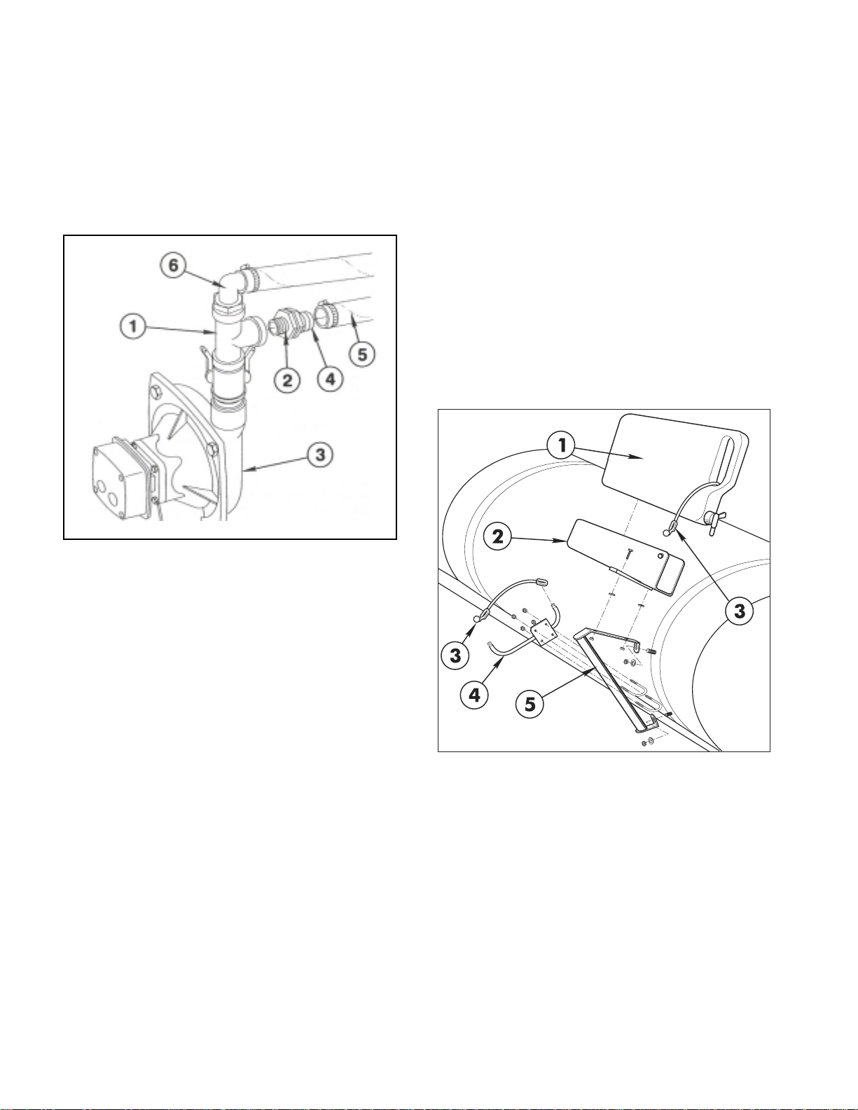
27. Apply thread sealer and install Reducing
Bushing into side of Tee on top of Pump. Install 1"
MPT x 3/4" hose barb into Reducing Bushing, and
attach one end of the Agitator Solenoid Feed
Hose. (See FIG. 10) Secure with a hose clamp.
Attach other end of hose to the 90° hose barb at
the side of the Agitator Solenoid. (See FIG. 9)
Secure with a hose clamp.
FRESH WATER TANK (Fig. 11)
1. Mount Brace assembly to the two (2) 5/16"
carriage bolts in the right side front Tank Band
using two (2) 5/16" flat washers and hex nuts.
Tighten securely.
NOTE: Left hold-in assembly and hardware will
not be used.
2. Mount Wash Tank Bracket (open end forward)
to right-hand Hold-In Brace assembly using two
(2) 5/16" x 1" hex hd. cap screws, flat washers,
and hex nuts. Place Clean Water Wash Tank into
Wash Tank Bracket and secure with Rubber HoldDown, as shown in FIG. 11.
NOTE: Tighten all fasteners and hose clamps
securely before using the spray system.
1142
Figure 10
1. Tee 4. Hose Barb
2. Reducing Bushing 5. Agitator Feed Hose
3. Pump 6. 90° Hose Barb
NOTE: If installing the "Enclosed Boom" option
in place of the Standard Boom, skip Steps 2830 and refer to the instructions furnished with
that kit before continuing with Step 31.
28. Attach the Boom Feeder Hoses to the barbs
in the Solenoids with hose clamps.
29. Place a hose clamp on the center Boom
Feeder Hose and attach it to the 90° Hose Barb at
the RH end of Center Boom Pipe.
30. Place a hose clamp on the right and left Boom
Feeder Hoses and attach them to the double barb
nozzles on the right and left Boom Pipes.
31. Install the "Anti-Siphon Kit". Instructions and
parts are included with your MULTI PRO
®
5500
Turf Sprayer.
Figure 11
1. Clean Water Wash Tank 4. Boom Hold-In Ass'y
2. Wash Tank Bracket 5. Hold-In Brace Ass'y
3. Rubber Hold-Down
NOTE: If installing the optional "Foam Marker
Kit", refer to the instructions furnished with
that kit for remaining set-up procedures.
14
BEFORE OPERATING
CAUTION
Servicing the vehicle while the engine is
running or vehicle is not properly secured
could result in personal injury or death.
Before servicing or making adjustments
to the vehicle, stop engine, set parking
brake, and remove key from the switch.
IMPORTANT! Check level of oil BEFORE EACH
USE, while engine is cool so the oil has had
some time to drain into the sump.
SINGLE VISCOSITY OILS
Outside Temperature
- 10°F to +60°F SAE 10W
+10°F to +90°F SAE 20W-20
Above +32°F SAE 30
Above +50°F SAE 40
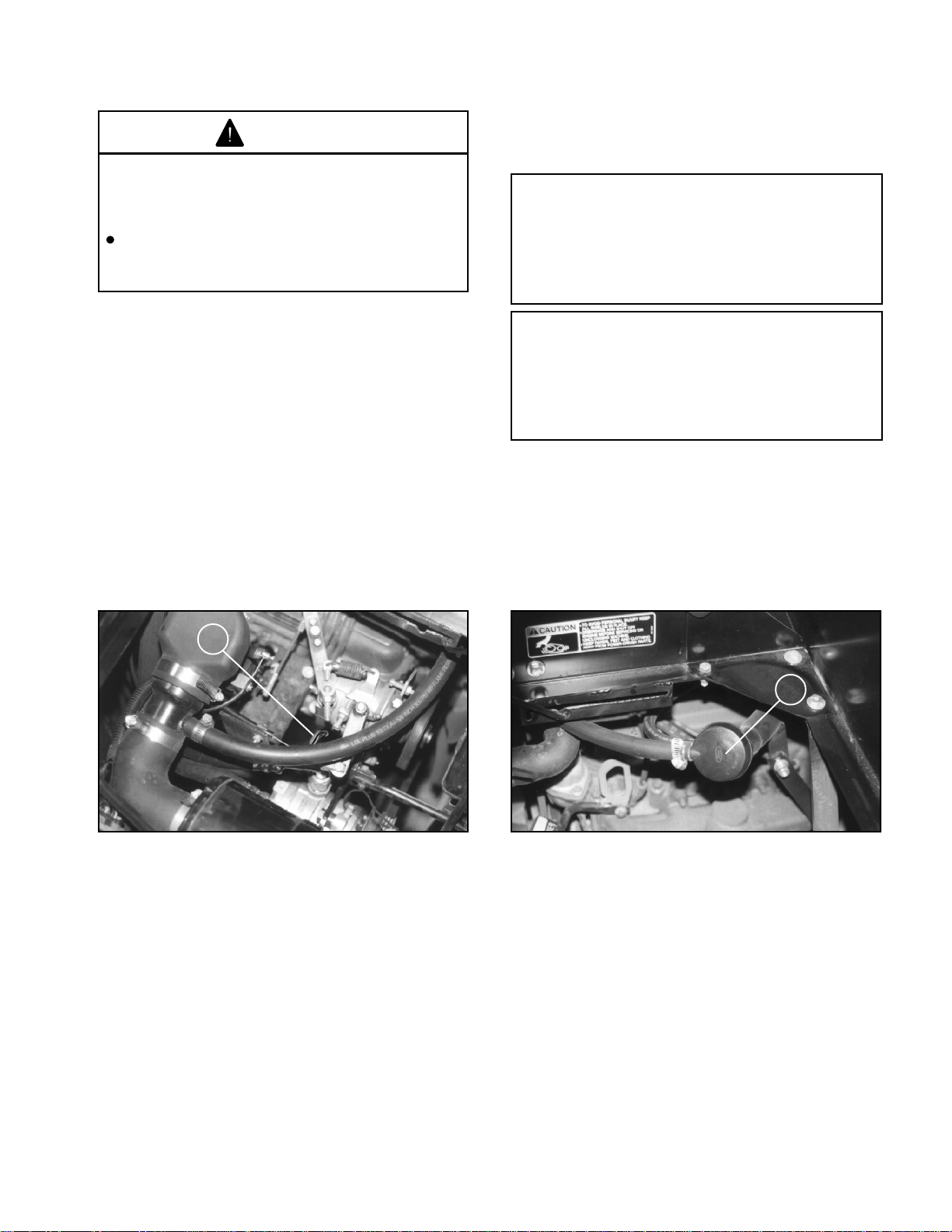
CHECK ENGINE OIL (Fig. 12 a, b)
The engine is shipped with approximately 3.5
quarts (3.25 liter) of oil in the crankcase; however,
level of oil must be checked before and after
the engine is first started.
1. Position vehicle on a level surface. Tilt right
seat forward to gain access to the engine
compartment.
2. Remove dipstick from oil tube, wipe clean,
and reinstall into the tube. Pull it out again and
check oil level on dipstick. Oil level must be
maintained between the minimum and maximum
marks on the dipstick.
MULTI-VISCOSITY OILS
Outside Temperature
Below +60°F SAE 5W-30
- 10°F to +90°F SAE 10W-20
Above -10°F SAE 10W-40 or 10W50
Above +50°F SAE 20W-40 or 20W50
Change oil and filter after the first 50 hours of
operation. Thereafter, change oil and filter after
every 100 hours of operation. Change oil more
frequently when engine is operated in extremely
dusty or dirty conditions. See page 32.
Figure 12 a
1. Oil Dipstick
3. If oil level is low, tilt drivers side seat forward,
remove oil fill cap, and add Ford or Motorcraft oil
or equivalent that meets Ford Specification ESEM2C153-E and API categories SG, SG/CC or
SG/CD until level is between the "MIN" and "MAX"
marks on the dipstick. DO NOT OVERFILL. See
viscosity chart for recommended weight to use.
4. Install the dipstick firmly in place.
5. Install oil fill cap.
6. Close access door and secure handle.
7. Lower seat to original seating position.
Figure 12 b
1. Filler Cap
15

BEFORE OPERATING
CAUTION
If engine has been running, pressurized
hot coolant can escape and cause burns
if cap is removed.
Before removing cap, allow engine to
cool for at least 15 minutes or until the
cap is not hot to the touch.
CHECK COOLING SYSTEM (Fig. 13)
Capacity of system is 12 quarts (11.5 liters). The
cooling system is filled with a 50/50 solution of
water and permanent ethylene glycol anti-freeze.
Check level of coolant at beginning of each day
before starting the engine.
1. Park machine on level surface and fold seats
forward.
1143
Figure 13
1. Coolant level 2. Radiator cap.
(3/4 to 1-1/2 inches
below cap seal.)
2. When engine is cool remove radiator cap
and check coolant level. Coolant level should be
approximately 3/4 to 1-1/2 inches below the filler
neck seat when the coolant is cold.
3. If coolant is low, add a 50/50 mixture of water
and antifreeze. DO NOT USE WATER ONLY OR
ALCOHOL/METHANOL BASE COOLANTS.
4. Replace radiator cap securely.
16
BEFORE OPERATING
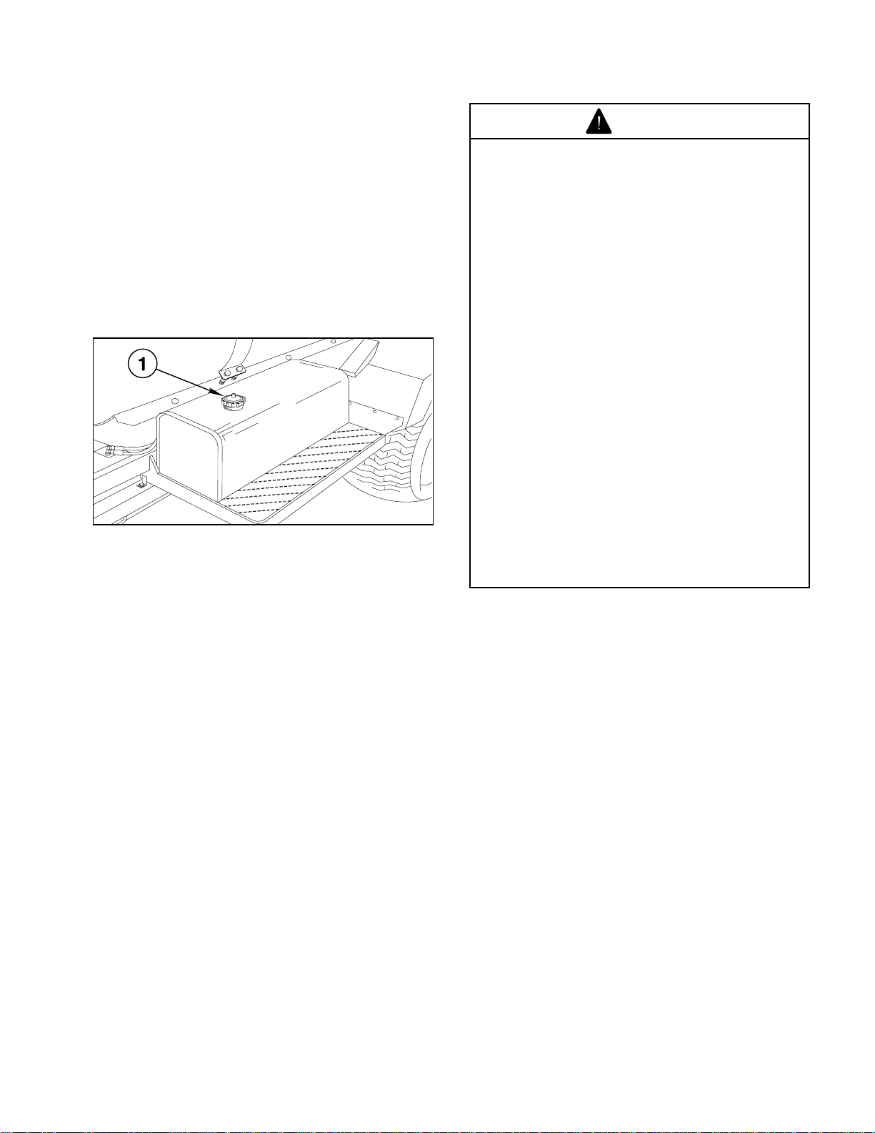
FILL FUEL TANK (Fig. 14)
Fuel tank capacity is 10.6 gallons (40 liters).
THE TORO COMPANY STRONGLY
RECOMMENDS THE USE OF FRESH, CLEAN
UNLEADED REGULAR GRADE GASOLINE IN
TORO GASOLINE POWERED PRODUCTS.
UNLEADED GASOLINE BURNS CLEANER,
EXTENDS ENGINE LIFE, AND PROMOTES
GOOD STARTING BY REDUCING THE BUILDUP
OF COMBUSTION CHAMBER DEPOSITS.
MINIMUM OCTANE RATING OF 87.
1144
Figure 14
1. Fuel tank cap.
DANGER
Because gasoline is flammable, caution
must be used when storing or handling
it. Do not fill fuel tank while engine is
running, hot, or when vehicle is in an
enclosed area. Vapors may build up and
be ignited by a spark or flame source
many feet away. DO NOT SMOKE while
filling the fuel tank to prevent the
possibility of an explosion. Always fill fuel
tank outside and wipe up any spilled
gasoline before starting the engine. Use
a funnel or spout to prevent spilling
gasoline, and fill tank no higher than one
inch below top of tank, (bottom of filler
neck). DO NOT OVER FILL. Store
gasoline in a clean safety approved
container and keep the cap on the
container. Keep gasoline in a cool, well
ventilated place; never in an enclosed
area such as a hot storage shed. To
assure volatility, do not buy more than a
30 day supply of gasoline. Gasoline is a
fuel for internal combustion engines;
therefore do not use it for any other
purpose. Since many children like the
smell of gas, keep it out of their reach
because the fumes are explosive and
dangerous to inhale.
IMPORTANT! NEVER USE METHANOL,
GASOLINE CONTAINING METHANOL,
GASOLINE CONTAINING MORE THAN 10%
ETHANOL, GASOLINE ADDITIVES, OR WHITE
GAS. ENGINE FUEL SYSTEM DAMAGE COULD
RESULT.
1. Clean area around fuel tank cap.
2. Remove fuel tank cap.
3. Fill tank to about one inch below top of tank
(bottom of filler neck). DO NOT OVERFILL. Then
install cap.
4. Wipe up any fuel that may have spilled to
prevent a fire hazard.
FUEL GAUGE: The Fuel Tank Cap shows amount
of fuel in tank.
17
BEFORE OPERATING
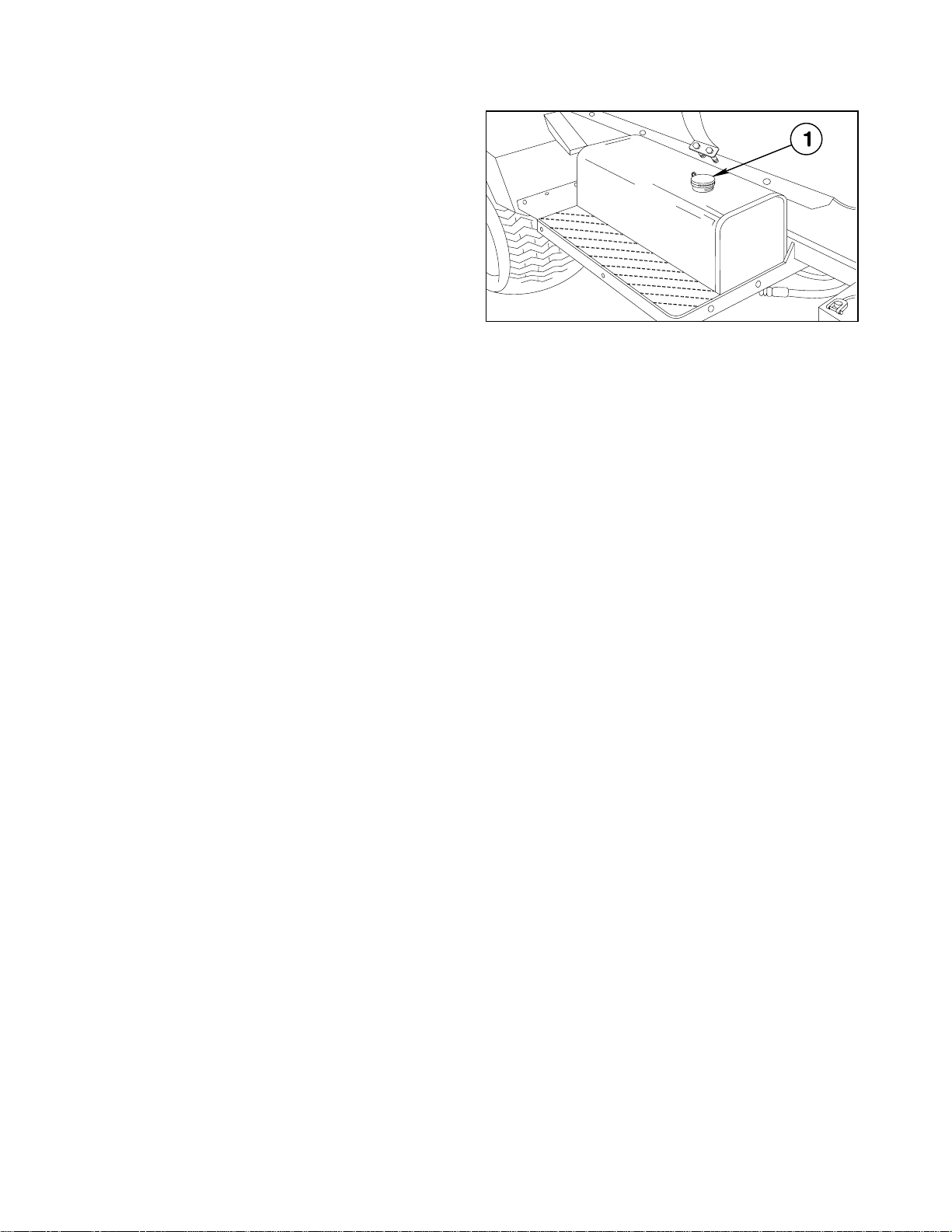
1145
CHECK HYDRAULIC FLUID (Fig. 15)
IMPORTANT! ALWAYS USE EXTREME
CAUTION WHEN FILLING THE RESERVOIR OR
CHECKING THE LEVEL OF THE HYDRAULIC
FLUID. KEEP THE SYSTEM FREE OF
CONTAMINANTS.
1. Position vehicle on a level surface, set parking
brake, and stop the engine
2. Clean area around filler neck and cap of
hydraulic tank. Remove cap from filler neck.
Figure 15
3. If level is low, add appropriate fluid to raise
level to two inches from top of the tank (bottom of
strainer) DO NOT OVERFILL.
4. Install cap onto filler neck.
5. Start engine.
6. Turn the steering wheel completely to the left,
then completely to the right.
7. Turn off the engine and recheck level of
hydraulic fluid. Replenish as required.
1. Hydraulic fluid tank cap.
The vehicle's reservoir is filled at the factory with
approximately 12 gallons (45.42 liters) of Mobil
424 hydraulic fluid. Check level of hydraulic fluid
before engine is first started and daily
thereafter.
18
BEFORE OPERATING
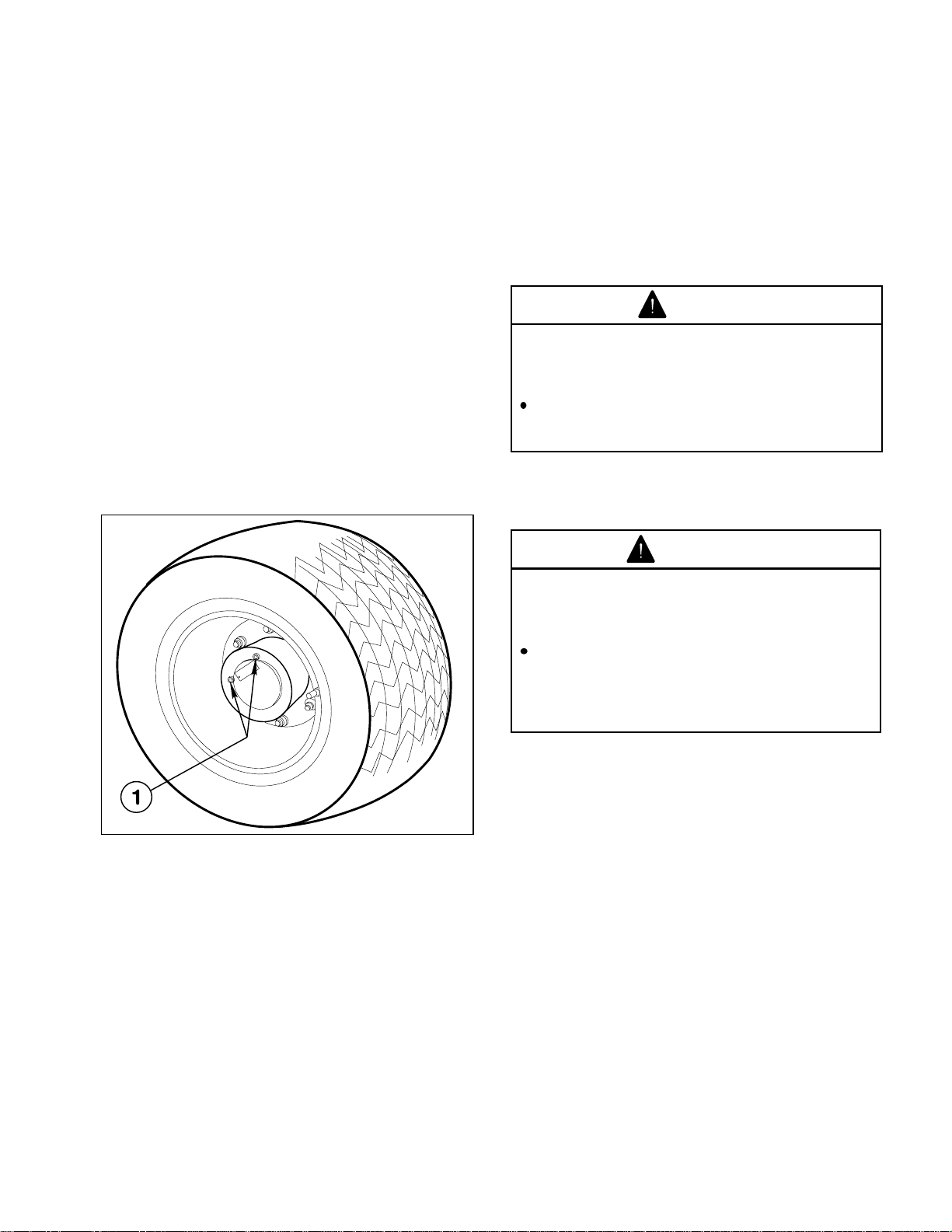
CHECK PLANETARY GEAR OIL
(Fig. 16)
Check oil if external leakage is noted. Use high
quality SAE 85W-140 wt. gear lube replacement.
Capacity of system is 16 oz.
1. With machine on level surface, position wheel
so check/drain plugs are at the 9 and 12 o'clock
position.
2. Remove the 9 o'clock positioned plug. Oil
should be to bottom of the hole.
3. If necessary add gear oil to the 12 o'clock hole
until oil begins to flow from the 9 o'clock hole.
4. Wipe surface clean and reinstall plugs.
5. Repeat steps 1 through 4 on opposite gear
assembly.
CHECK EMERGENCY/PARK BRAKE
Adjust the Emergency/Park Brake when there is
more than 1 inch of "free travel" of the Brake Pedal,
or if the Brake does not work effectively. "Free
travel" is the distance the Brake Pedal moves
before braking resistance is felt. To reduce "free
travel" of brake pedal see the MAINTENANCE
section on "ADJUSTING BRAKES".
DANGER
Operating the vehicle with worn or poorly
adjusted brakes can result in serious
injury or death.
If Brake Pedal travels to within 1 inch of
the Vehicle floor board, the brakes must
be adjusted or repaired.
CHECK TORQUE OF WHEEL NUTS
WARNING
1146
Figure 16
1. Check/Drain Plugs
Failure to maintain proper torque could
result in failure or loss of wheel and may
result in personal injury.
Torque front wheel nuts to 55-65 ft-lb (7588N-m) and rear wheel nuts or bolts to
85-100 ft-lb (116-136 N-m) after 1-4 hours
of operation and every 200 hours
thereafter.
IMPORTANT! After the "initial run-in"
(approximately one to two hours) check all the
MULTI PRO
tightness.
®
5500 wheel fasteners for
CHECK TIRE PRESSURE
Check tire pressure every 8 hours or daily to assure
proper levels. Maximum air pressure in both front
and rear tires is 18 p.s.i.
The air pressure needed is determined by the
payload carried. Once the desired pressure has
been ascertained, it is to be used and maintained
to insure the accuracy of the spraying system.
INSPECT TIRES
Check tire condition for wear or damage.
Operating accidents, such as hitting curbs, can
damage a tire or rim and also disrupt wheel
alignment, so inspect tire condition after any
accident.
19
VEHICLE CONTROLS
Familiarize yourself with the controls and
recommended operating procedures before
operating the MULTI PRO
TRACTION PEDAL: (Fig. 17) Controls forward
and reverse operation. Depress top of pedal to
move forward and bottom of pedal to move
backward. Ground speed depends on how far
pedal is depressed. For maximum ground speed,
fully depress pedal while throttle is in FAST.
To stop, reduce foot pressure on traction pedal
and allow it to return to center position.
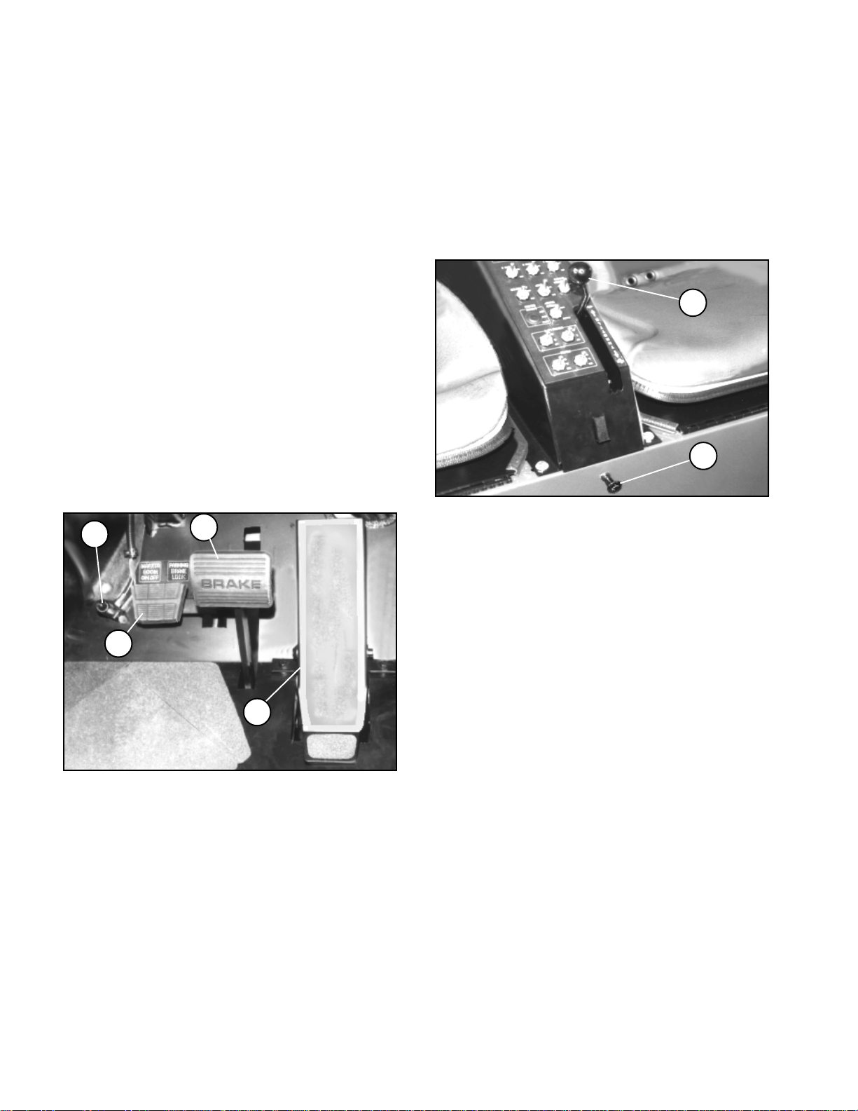
EMERGENCY/PARKING BRAKE PEDAL:
(Fig. 17) Functions as a parking brake and an
emergency brake in situations demanding an
immediate stop.
BRAKE LOCK: (Fig. 17) The small pedal to the
left side of the brake pedal actuates the parking
brake lock. To engage parking brake, fully depress
brake pedal and depress brake lock which locks
brake pedal. To release parking brake, fully
depress brake pedal to release brake lock.
"
®
5500.
THROTTLE CONTROL: (Fig. 18) Move control
forward, toward "FAST", to increase engine speed,
rearward, toward "SLOW", to decrease engine
speed. Set at 1/4 to 1/3 throttle when starting
engine.
MANUAL CHOKE: (Fig. 18) Pull OUT when
starting cold engine, gradually push IN after
successfully starting engine.
Figure 18
1. Throttle control 2. Manual Choke
!
Figure 17
1. Traction Pedal 3. Brake Lock
2. Brake Pedal 4. Remote Master Switch
REMOTE BOOM ON/OFF SWITCH: (Fig. 17) Is
in series with the MASTER BOOM ON/OFF switch;
The operator must first turn on the Master Boom
ON/OFF switch on the center console; then click
on the Remote Boom ON/OFF Switch on the floor
board.
20
 Loading...