

Page 1
FORM NO. 3319-870 GB Rev A
© The T oro Company—1998
®
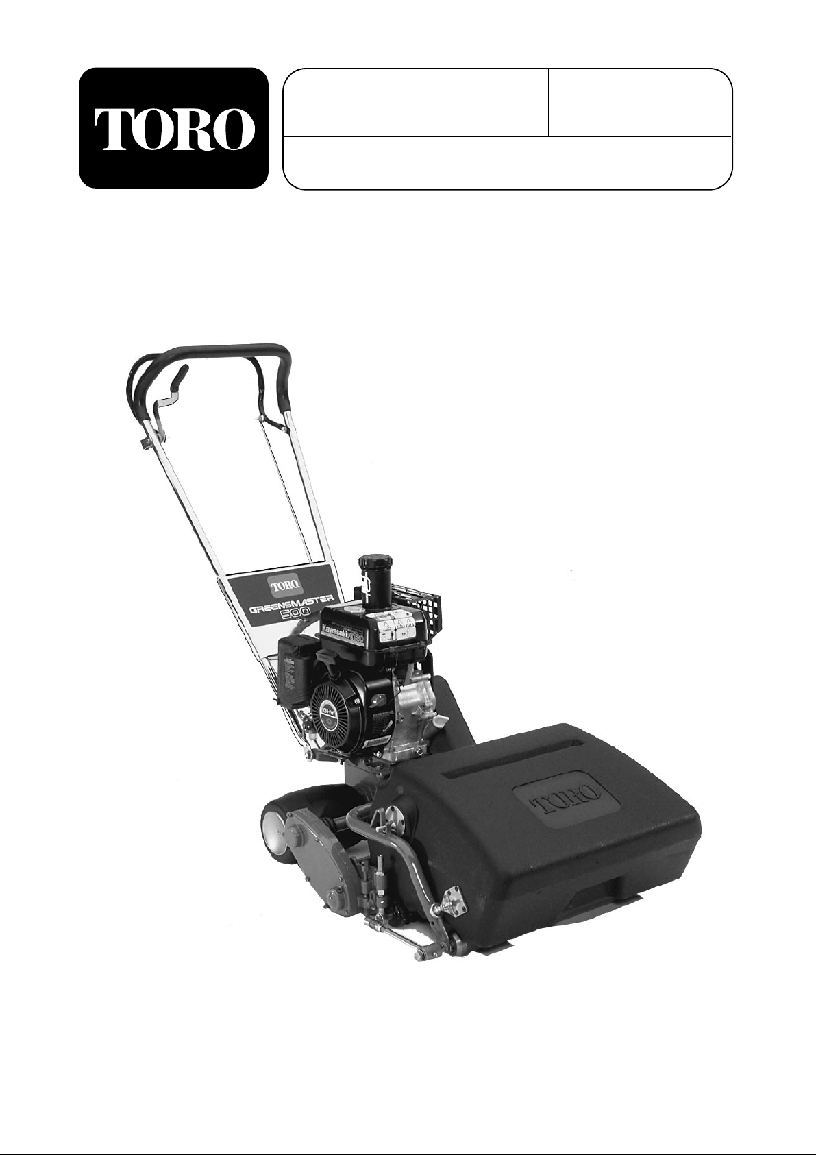
MODEL NO. 04130—80001 & UP
GREENSMASTER
OPERATOR’S
MANUAL
®
500
Page 2

To assure maximum safety, optimum performance,
and to gain knowledge of the product, it is essential
that you or any other operator of the mower read and
understand the contents of this manual before the
engine is ever started. Pay particular attention to the
SAFETY INSTRUCTIONS highlighted by this symbol:
The safety alert symbol means CAUTION, WARNING or DANGER—personal safety instruction.
Failure to comply with the instruction may result in
personal injury.
FOREWORD
The GREENSMASTER 500 was developed to satisfy the demand for a maneuverable, intermediate size,
turf maintenance rotary mower. The machine has
advanced concepts in engineering, design and safety;
and if maintained properly, it will give excellent service.
Since the GREENSMASTER 500 is a high quality
product, Toro is concerned about the future use of
the machine and the safety of the user. Read this
manual to familiarize yourself with the proper set up,
operation, and maintenance instructions.
Certain information in this manual is emphasized.
DANGER, WARNING and CAUTION identify personal safety related information. IMPORTANT identifies mechanical information demanding special
attention. Be sure to read the directive because it
deals with the possibility of damaging a part or parts
of the machine. NOTE identifies general information
worthy of special attention.
If help concerning set up, operation, maintenance or
safety is ever needed, contact a local Authorized
Toro Distributor. In addition to genuine Toro replacement parts, the distributor also has optional equipment form the complete line of Toro turf care equipment. Keep your Toro all Toro – buy genuine Toro
replacement parts and accessories.
Whenever you have questions or need service, contact your local authorized Toro Distributor. In addition to having a complete line of accessories and
professional turf care service technicians, the distributor has a complete line of genuine TORO replacement parts to keep your machine operating properly.
Keep your TORO all TORO. Buy genuine TORO
parts and accessories.
TABLE OF CONTENTS
SAFETY INSTRUCTIONS 3
SPECIFICATIONS 8
BEFORE OPERATING 9
CONTROLS 14
OPERATING INSTRUCTIONS 15
MAINTENANCE 17
PRODUCT IDENTIFICATION 21
2
Page 3

3
Safety
Before Operating
1. Read the instructions carefully. Be familiar
with the controls and the proper use of the
equipment.
2. Never allow children or people unfamiliar with
these instructions to use the machine. Keep
everyone, especially children and pets away
from the area of operation
3. Become familiar with the controls and know
how to stop the machine quickly
4. Keep all shields, safety devices and decals in
place. If a shield, safety device or decal is
defective or damaged, repair or replace it before
operating the machine.
5. Always wear substantial shoes. Do not operate
the machine while wearing sandals, tennis shoes
or sneakers. Do not wear loose fitting clothing
that could get caught in moving parts and cause
personal injury.
6. Wearing safety glasses, safety shoes, long pants
and a helmet is advisable and required by some
local safety and insurance regulations.
7. Be sure the work area is clear of objects that
might be picked up and thrown by the reel.
8. keep everyone, especially children and pets,
away from the areas of operation.
9. Since gasoline is highly flammable, handle it
carefully.
A. Use an approved gasoline container.
B. Do not remove the cap from the fuel tank
when the engine is hot or running.
C. Do not smoke while handling gasoline.
D. Fill the fuel tank outdoors and not over one
inch (25 mm) from the top of the tank, not
the filler neck. Do not overfill.
E. Wipe up any spilled gasoline.
While Operating
10. Do not run the engine in a confined area with-
out adequate ventilation. Exhaust fumes are
hazardous and could be deadly.
11. Always stand behind the handle when starting
and operating the machine.
12. Do not touch the engine, muffler or exhaust pip
while the engine is running or soon after it is
stopped because these areas could be hot
enough to cause burns.
13. If you leave the machine unattended, be sure to
stop the engine so the cutting reel is not spinning.
Maintenance
14. Before servicing or making adjustments to the
machine, stop the engine and pull the wire from
the spark plug to prevent accidental starting.
15. To reduce potential fire hazard, keep the engine
area free of excessive grease, grass, leaves and
dirt.
16. If the engine must be running to perform a
maintenance adjustment, keep hands, feet,
clothing and any part of the body away from the
cutting unit and any moving parts. Keep everyone away.
17. Do not overspeed the engine by changing the
governor settings. Maximum engine speed is
3000 rpm. To assure safety and accuracy, have
an authorized Toro distributor check engine
speed with a tachometer.
18. Shut off the engine before checking or adding
oil.
19. Check the performance of the clutch system
daily. Do not defeat this system, it is for your
own protection.
Page 4

Safety
4
Sound & Vibration Levels
Sound Levels
This unit has an equivalent continuous A-weighted
sound pressure at the operator ear of: 82.5 dB(A),
based on measurements of identical machines per
91/386/EEC.
This unit has a sound power level of 94.5 LWA,
based on measurements of identical machines per
procedures outlined in Directive 84/538/EEC and
amendments
Vibration Levels
This unit has a vibration level of 10.05 m/s2at the
hands/arms, based on measurements of identical
machines per ISO 5349 procedures.
Page 5
5
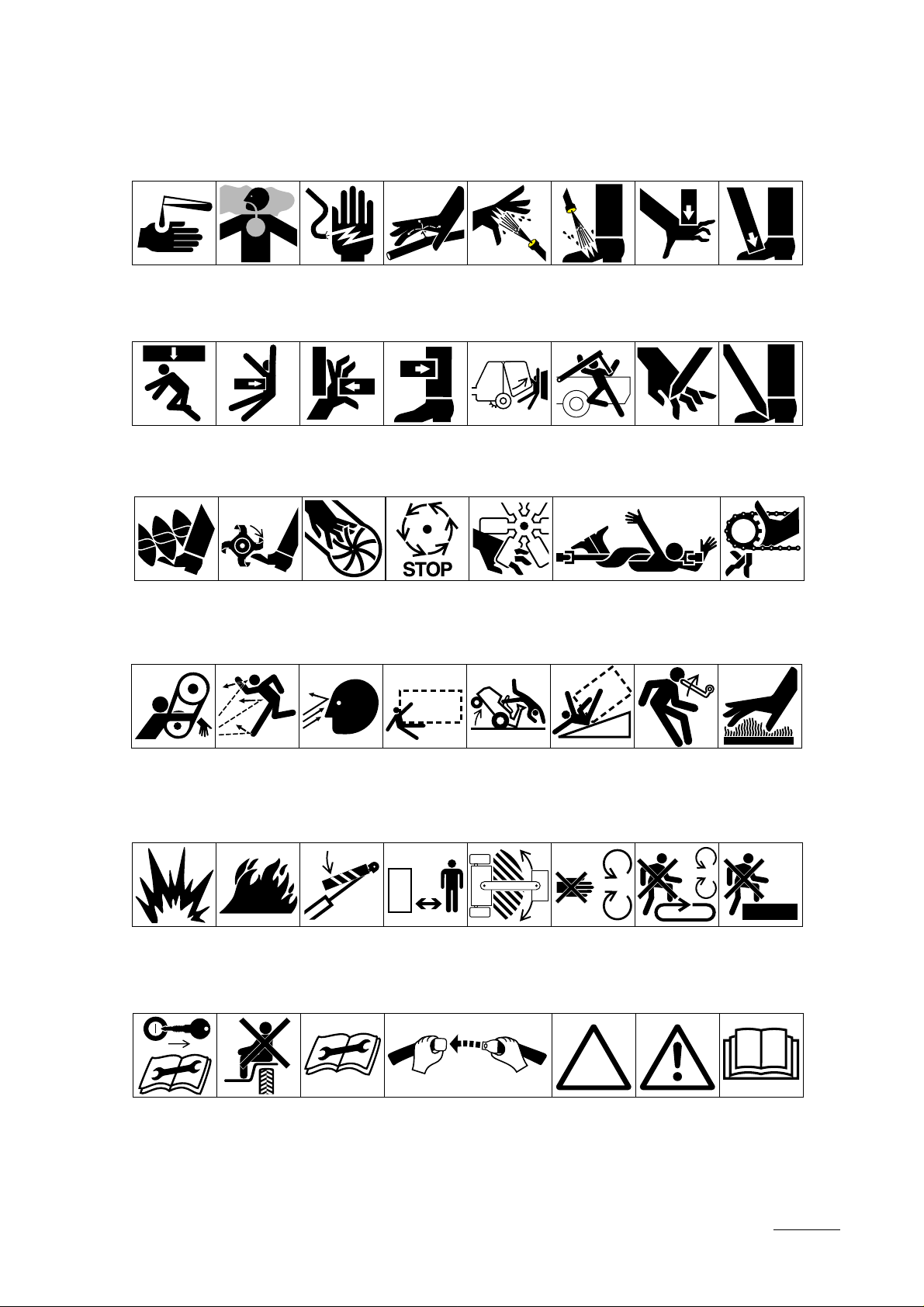
Symbol Glossary
Caustic liquids,
chemical burns to
fingers or hand
Poisonous
fumes or toxic
gases, asphyxiation
Electrical shock,
electrocution
High pressure
fluid, injection
into body
High pressure
spray, erosion of
flesh
High pressure
spray, erosion of
flesh
Crushing of
fingers
or hand,
force
applied from
above
Crushing of
toes or foot, force
applied from above
Crushing of
whole body,
applied from
above
Crushing of
torso, force
applied from side
Crushing of fingers
or hand/, force
applied from side
Crushing of
whole body
Crushing of
head, torso and
arms
Cutting of
fingers or hand
Cutting of footCrushing of leg,
force applied
from side
Cutting or
entanglement of
foot, rotating auger
Severing of
foot, rotating
knives
Severing of
fingers or hand,
impeller blade
Wait until all
machine
components have
completely stopped
before touching them
Severing of
fingers or hand,
engine fan
Whole body entanglement,
implement input drive line
Fingers or
hand entanglement, chain drive
Runover/backover, (relevant
machine to appear
in dashed box)
Machine tipping,
riding mower
Machine rollover,
ROPS (relevant
machine to appear
in dashed box)
Stored energy
hazard, kickback
or upward motion
Hot surfaces,
burns to fingers
or hands
Hand & arm
entanglement,
belt drive
Thrown or flying objects, whole
body exposure
Thrown or
flying objects,
face exposure
Explosion Fire or open
flame
Secure lifting
cylinder with locking
device before getting
in hazardous area
Stay a safe
distance from
the machine
Stay clear of
articulation area
while engine is
running
Do not open
or remove safety
shields while
engine is
running
Do not step on
loading platform if
PTO is connected to tractor
& engine is running
Do not step
Shut off engine
& remove key before
performing maintenance or repair work
Riding on this
machine is allowed
only on a passenger seat & only if the
driver’s view is not
Consult
technical manual
for proper service
procedures
Fasten seat belts Safety alert
triangle
outline safety
alert symbol
Read operator’s
manual
Page 6

Safety
6
Eye protection
must be worn
Fire, open light
& smoking
prohibited
Level
indicator
Head protection
must be worn
Hydraulic
system
Liquid level Filter Temperature Failure/
Hearing
protection must
be worn
Brake system
Caution, toxic
risk
Oil Coolant (water) Intake air Exhaust gas Pressure
First aid
Malfunction
Flush with water Engine Transmission
Start switch/
mechanism
On/start Off/stop
Engage Disengage
Horn Battery charging
Machine travel
direction,
forward/rearward
Jack or
support point
condition
Control lever
operating
direction, dual
direction
Draining/
emptying
Attachment
lower
Hourmeter/elapsed
operating hours
Control lever
operating
direction, multiple
direction
Engine lubricating oil
Attachment
raise
Fast Slow Continuous
Clockwise
rotation
Engine lubricating
oil pressure
Spacing distance Snow thrower,
Counter-clockwise rotation
Engine lubricating
oil level
collector auger
variable, linear
Grease
lubrication
point
Engine lubricating
oil filter
Plus/increase/
positive polarity
Volume empty Volume full
Oil lubrication
point
Engine
lubricating oil
temperature
Minus/decrease/
negative polarity
Lift point
Engine coolant
Page 7

7
Safety
Transmission
failure/malfunction
Clutch Neutral High Low Forward Reverse Park
N H L F R P
First gear Second gear
Third gear (other #'s
may be used until
the maximum # of forward gears is reached.)
Hydraulic oil Hydraulic oil
temperature
2 31
Hydraulic oil
pressure
Hydraulic oil level Hydraulic oil filter
Hydraulic oil
failure/malfunction
Parking brake Fuel Fuel level Fuel filter Fuel system
failure/malfunction
Diesel fuel Unleaded fuel
Headlights Lock Unlock Differential lock 4-Wheel drive Power Take-Off Power Take-Off,
rotational speed
Reel cutting
element
Reel cutting
element, height
adjustment
Traction Above working
temperature range
Drilling Manual metal arc
welding
Manual 0356 Water pump
0626 Keep dry
0430 weight Do not dispose
in the garbage
CE logo
Engine failure/
malfunction
Engine rotational
speed/frequency
Choke Primer (start aid) Electrical preheat
(low temperature
start aid)
Transmission oil Transmission oil
pressure
n/min
Transmission oil
temperature
Page 8

Engine: 3.7 horsepower (2.7 kw) engine with 2.64
quarts (2.5 l) capacity gas tank.
Handle: 7/8 in.(22 cm) diameter, 17-gauge welded
steel tubing with formed steel reinforcement panel.
Traction Unit: Cast aluminum housing.
Reel Unit: Cast aluminum and zinc side plates, alu-
minum extrusion back plate. Reel unit independent
of traction unit and catcher.
Front Rollers: 2 in. (51 mm) O.D. Steel tube with
ball bearings, moisture excluding oil seals and
replaceable wear sleeves.
Height Of Cut: 1/8 to 11/16 in. (3 to 17 mm).
(Optional micro-cut bedknife 6mm to 24)
Width Of Cut: 21 in. (0.53 m).
Clip: 0.197 in. (5.0 mm).
Ground Speed: 2.1 mph (3.4 Km/hr) at 1600 RPM
and 4.0 mph (6.4 Km/hr.) at 3100 RPM.
Traction Drive: "A” section "V" belt on 2.0 pitch
diameter and 3.70 pitch diameter. to countershaft (1.
85:1) 18T and 48T gear 2.67:1 and 20T and 56T
gear (2. 8:1). All gears 16 pitch, 20° involute full
depth, 1/2 in. (13 mm) wide. Gears running in oil.
Reduction, Engine to Traction Drum: 13.86:1.
Traction Drum: 6 in. (15.2 cm) diameter solid rub-
ber on 16 gauge (1.5 mm) steel rims. Two sections
running on ball bearings.
Traction Drive Clutch: Friction Disk type—Hand
operated latch and bail at handle.
Differential: Enclosed spur gears.
Reel Drive: “A” section V-belt on 2.0 RD. and 3.70
RD. to countershaft (1. 85:1) 3/8 in. pitch x 3/16 in.
wide chain on 20T and 14T sprockets from counter-
shaft. Reduction Engine to Reel—1.30:1.
Reel Clutch: Engaging jaw type—hand operated at
the transaxle.
Reel: 3-1/2 in. (89 mm) diameter 9-blade, welded
tubular construction. Reel blades, high carbon heat
treated steel. Reel bearings, taper roller with adjustment.
Bedknife and Bar: Single-edge high carbon steel
knife, extra hard for long life, screwed to extruded
aluminum one-piece bed bar and back plate.
Dimensions:
Width: 27 in. (0.69 m)
Height: 44-3/4 in. (1.1 m) with handle
Length: 60 in. (1.5 m) including handle and catcher
Weight: 69 kilograms with catcher and cutting unit.
Optional Equipment:
Cutting Unit Model 04216
Brush Kit Part No. 2-2949
Skid Kit, Part No. 4-7299
Sectional Roller Kit Part No. 4-7319
Urethane Comb Kit Part No. 8-2560
Full Roller Kit Part No. 4-7309
Micro-cut Bedknife Part No. 95-3147
8
Specifications
Page 9
9
CHECK ENGINE OIL BEFORE
EACH USE OR EVERY 5 OPERATING HOURS
Refer to the Engine Operator's Manual for oil
requirements.
1. Position the mower on a level surface.
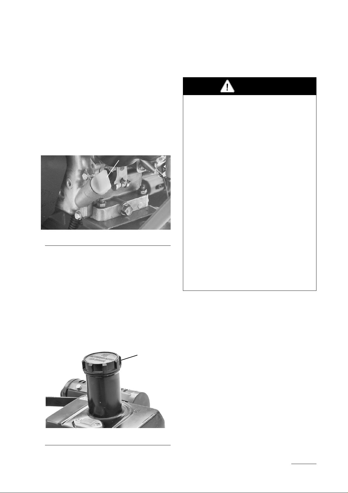
2. Clean around the oil gauge (Fig. 1) then remove
it by turning it counterclockwise.
Figure 1
1. Oil level gauge
3. Wipe it clean and re-insert it, but do not screw
it into the port. Then remove it and check the
oil check level. Add only enough oil to raise
the level to the filler opening.
FILL THE FUEL TANK
1. Clean around fuel tank cap and remove cap
from tank (Fig. 2). Fill the fuel tank no higher
than to the bottom of the filter screen. DO NOT
OVER FILL.
Figure 2
1. Fuel tank cap
3. Install fuel tank cap and wipe up any spilled
gasoline.
CHECK TRANSAXLE OIL LEVEL
Check the transaxle oil level before initial startup
and after every 50 hours of operation.
1. Place mower on level surface and remove the
plug at the rear of the gear case. Oil should be
to the bottom of the hole (Fig. 3).
2. If the level is too low, remove the plug in the
top cover (Fig. 4) and add SAE 90 gear oil.
3. To drain the transaxle, remove both plugs and
tip the unit rearward
1
1
Before Operating
Because fuel is flammable, caution must be used
when storing or handling it. Do not fill the fuel
tank while the engine is running, hot or when the
machine is in an enclosed area. Vapors may
build up and be ignited by a spark or flame
source many feet away. DO NOT SMOKE
while filling the fuel tank to prevent the possibility of an explosion. Always fill the fuel tank
outside and wipe up any spilled fuel before starting the engine. Use a funnel or spout to prevent
spilling, and fill the tank no higher than 2.5 cm
(one inch) below top of the tank, (bottom of the
filler neck). DO NOT OVER FILL.
Store fuel in a clean safety approved container
and keep the cap on the container. Keep fuel in
a cool, well-ventilated place; never in an
enclosed area such as a hot storage shed. To
assure volatility, do not buy more than a 30-day
supply of gasoline, or a 6-month supply of diesel
fuel.
Since many children like the smell of gasoline,
keep it out of their reach because the fumes are
explosive and dangerous to inhale.
DANGER
Page 10
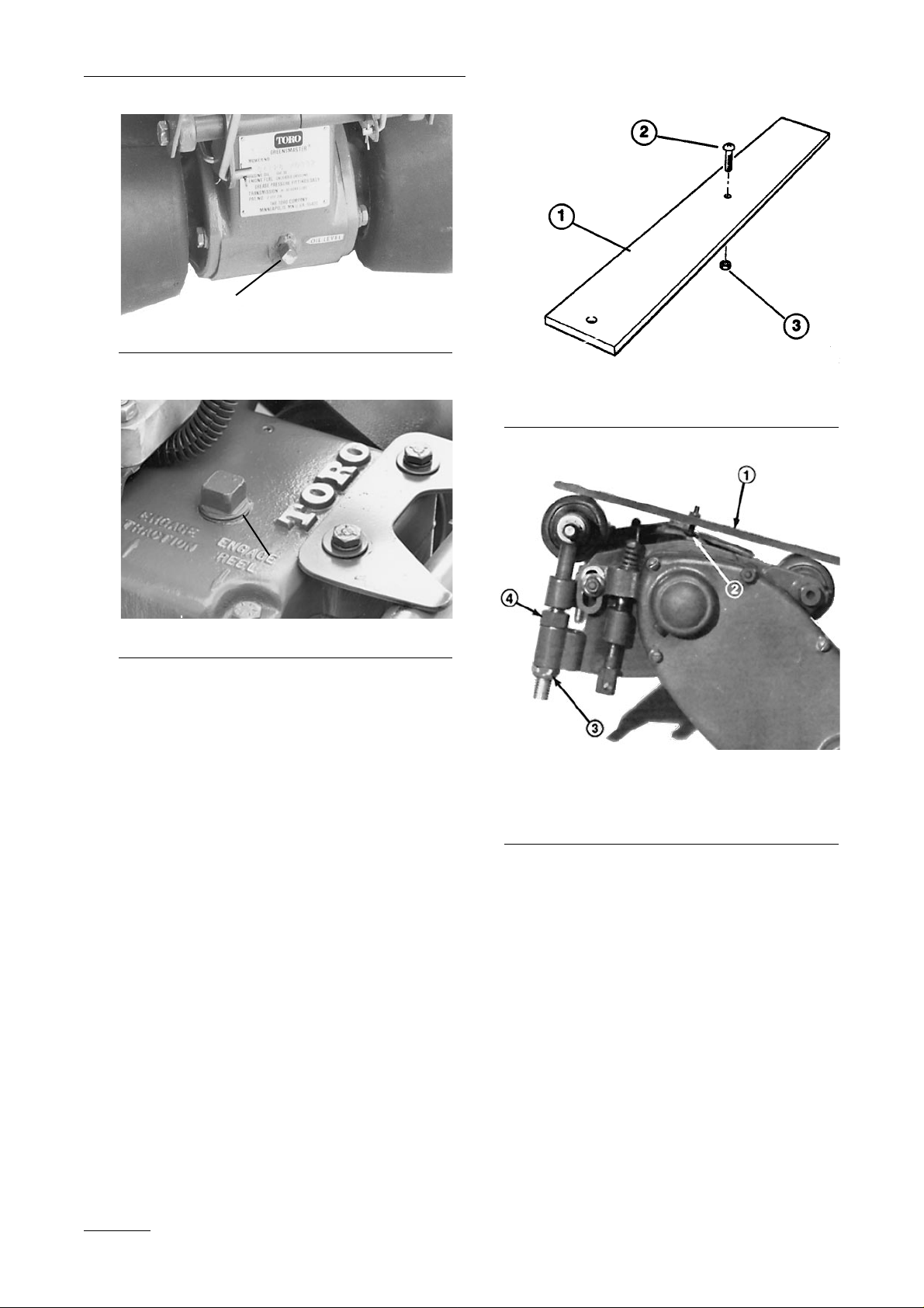
Figure 3
1. Plug
Figure 4
1. Transaxle oil fill plug
ADJUSTING HEIGHT OF CUT
You can select rollers, skids or bedknives suitable for
all types of greens turf grasses. For example, progressively lower heights of cut with the same gauge
setting may be obtained by selecting,, in the following order: the skid, full front roller, sectional roller
or the Wiehle roller. The micro-cut bedknife provides a height of cut to 1/16 (2 mm) inch, if desired.
1. Loosen the nut on the gauge bar and set the
adjusting screw to obtain the desired distance
between the bottom of the screw head and the
face of the bar (Fig. 5). Tighten the nut, making
sure adjustment is not altered.
2. Remove the cutting unit; refer to Removal and
Installation of the Cutting Unit.
3. Place the cutting unit upside down on a bench,
position the gauge bar on the end of the unit
with one end on the front support: skid, full
roller, sectional roller, etc., the other end on the
rear roller (Fig. 9).
Figure 5
1. Gauge bar
2. Height adjustment screw
3. Nut
Figure 6
1. Gauge bar against rollers
2. Screw head over cutting edge
3. Top nut
4. Adjustment nut
4. Loosen the top nut on the adjusting screws on
each side plate (Fig. 6) and turn the nut to raise
or lower the front roller or skid assembly.
Adjust to make contact with the outer end of the
gauge bar. When proper adjustment is obtained,
the screw head on the gauge bar will just pass
over the cutting edge of the bedknife. ASSURE
HEIGHT OF CUT IS EXACTLY IDENTICAL
AT BOTH ENDS OF THE BEDKNIFE.
5. Tighten the top nuts to secure roller adjustment
(Fig. 6). Turn the cutting unit over and place it
on a level surface (Fig. 7). Press down on each
end of the front and rear rollers (Fig. 7). Each
roller should contact a level surface completely
across the unit (Fig. 7). If the rollers do not
Before Operating
10
1
1
Page 11
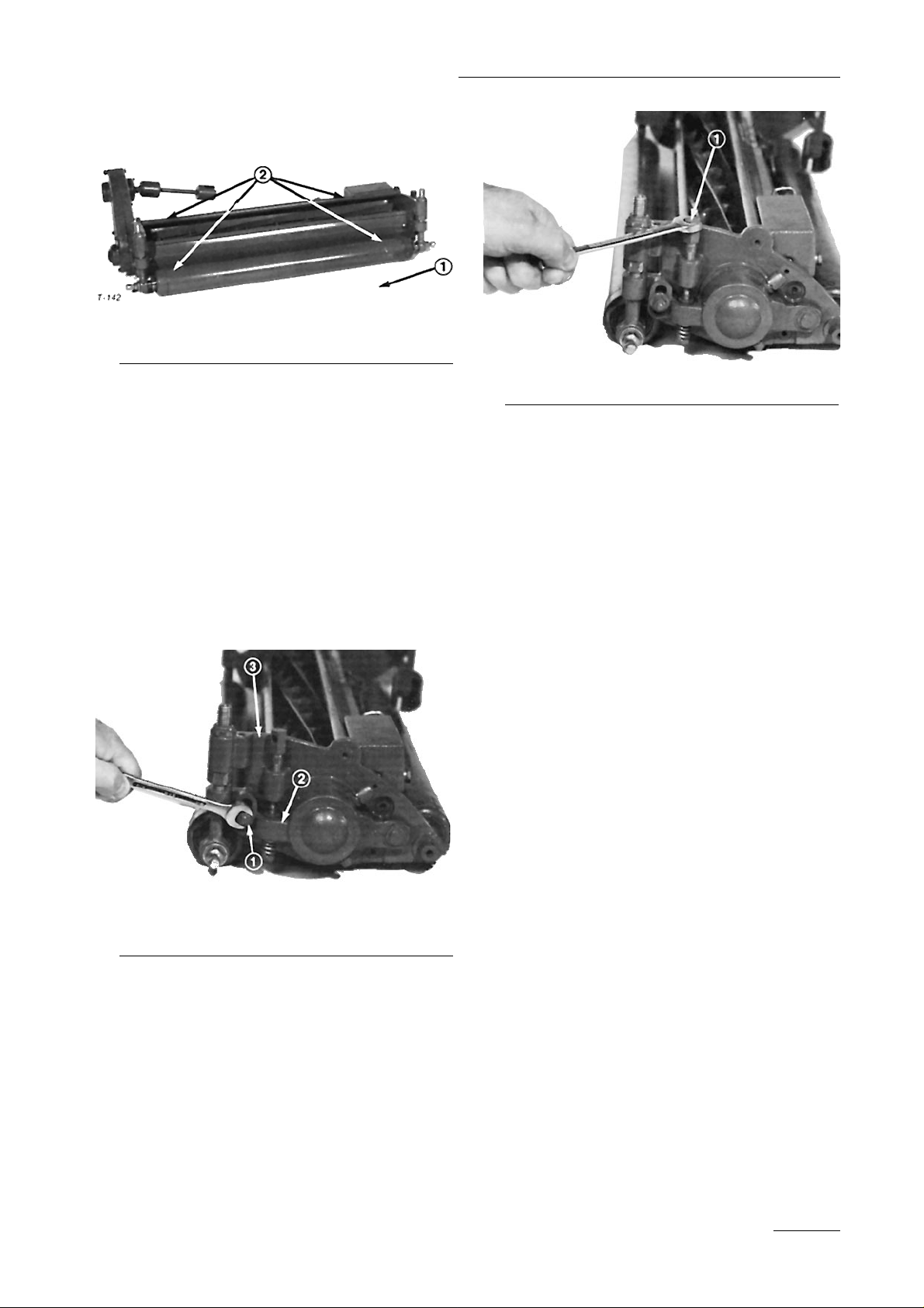
contact, repeat steps 3 and 4.
Figure 7
1. Level surface
2. Press down
REEL-TO-BEDKNIFE
ADJUSTMENT
1. Loosen the nuts securing the left and right reel
brackets to the side plates (Fig. 8).
2. Adjust reel-to-knife clearance with the adjusting
screws at each end of the unit (Fig. 9). NEVER
ALLOW THE BEDKNIFE TO BEAR HEAVILY AGAINST REEL.
Figure 8
1. Nut
2. Reel bracket
3. Side plate
Figure 9
1. Reel adjusting screw
3. Place a newspaper at right angles to the top face
of the bedknife against the front cutting edge
and rotate the reel blades against the paper. The
reel blades should cut the paper cleanly all
across the bedknife. If the paper is not cleanly
cut, the mower should be either backlapped or
resharpened; refer to Backlap Operation and
Reel and Bedknife Grinding.
4. Place a strip of newspaper flat on the top face
of the bedknife and adjust the reel down until
the reel blades pinch the paper equally all
across the bedknife.
5. Tighten the nuts to secure the adjustment.
ADJUST REAR ROLLER
SCRAPER
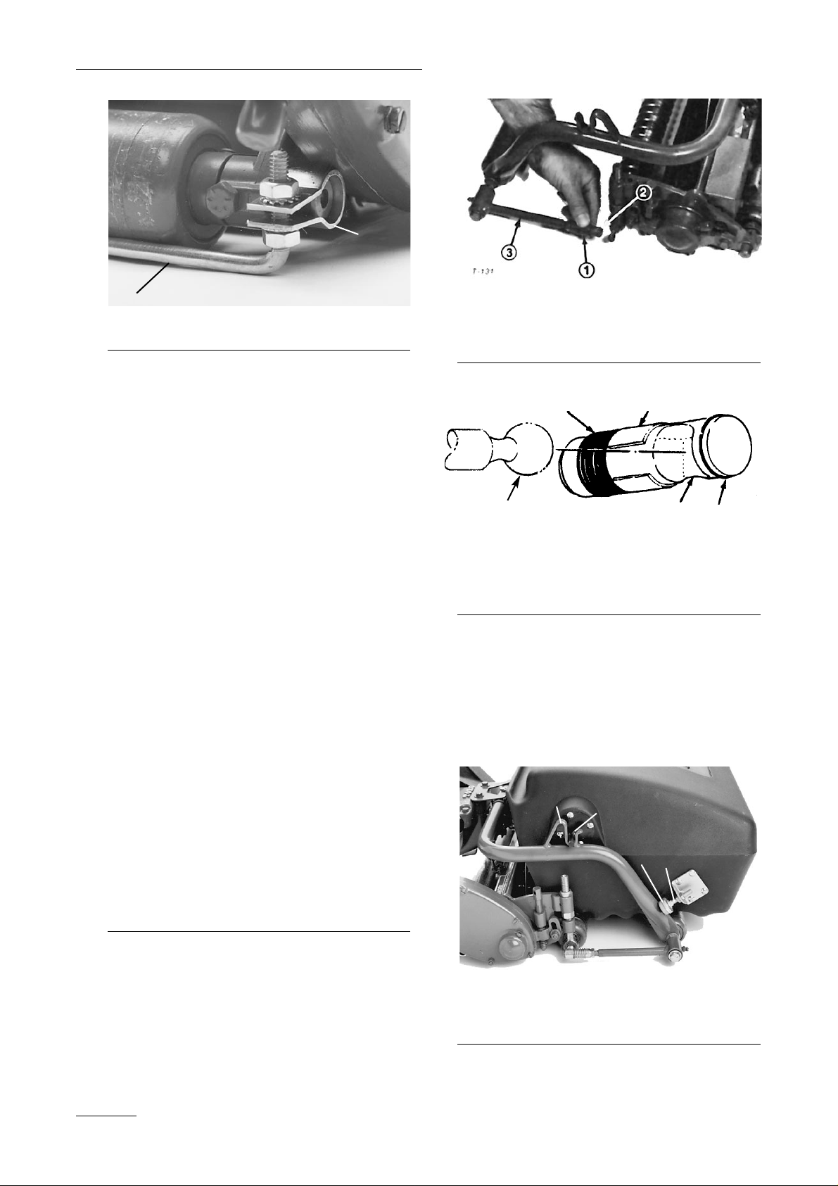
1. Adjust the scraper rod locknuts and brackets to
attain .06"–.10" (1.5– 2.5 mm) clearance
between the scraper rod and the roller surface.
The distance between the bottom of the rod and
the level surface should be the same height as
the height-of-cut setting.
2. Assure scraper rod is parallel to the roller and
level surface.
Note: Readjust the height of the scraper rod if
height-of cut is changed.
11
Before Operating
Page 12
Before Operating
12
Figure 10
1. Scraper rod
2. Bracket
CHECK CUTTING UNIT
ALIGNMENT
The cutting unit must be in alignment with the front
yoke roller so that the machine will track in a
straight line across the greens. Also, the driveshaft
must also be aligned with the transaxle shaft.
Alignment procedures:
1. Loosen the jam nut securing the ball sockets to
the pull arms on both sides of the yoke
(Fig. 11).
2. Slide back the sleeves on each ball joint and
rotate each pull arm upward off the ball studs.
3. Align the cutting unit with the roller and drive-
shaft with the transaxle shaft and lengthen or
shorten the pull rods by threading the ball socket on the rod (Fig. 11).
4. Align the ball sockets with the ball studs so the
hooded portion of the socket is at the top and
the open side is toward the stud (Fig. 12).
5. Slide the sleeve back on the ball joint and rotate the pull
arm down so the socket fits over the ball stud. Release the
sleeve so it slides forward over the stud and locks the
assemblies together. Tighten the jam nuts to secure the
sockets in position (Fig. 15).
Figure 11
1. Jam nut
2. Ball socket
3. Ball stud
Figure 12
1. Spring
2. Sleeve
3. Socket ball joint receiver
4. Retaining ring
4. Ball Stud
INSTALL THE GRASS CATCHER
1. Set the studs on the catcher pivots into the
brackets on the yoke and allow the catcher
adjusting screw to rest onto the yoke (Fig. 13).
Figure 13
1. Catcher pivot
2. Yoke bracket
3. Adjusting screw
4. Jam nut
1
1
1
5
2
3
4
1
2
3
4
Page 13
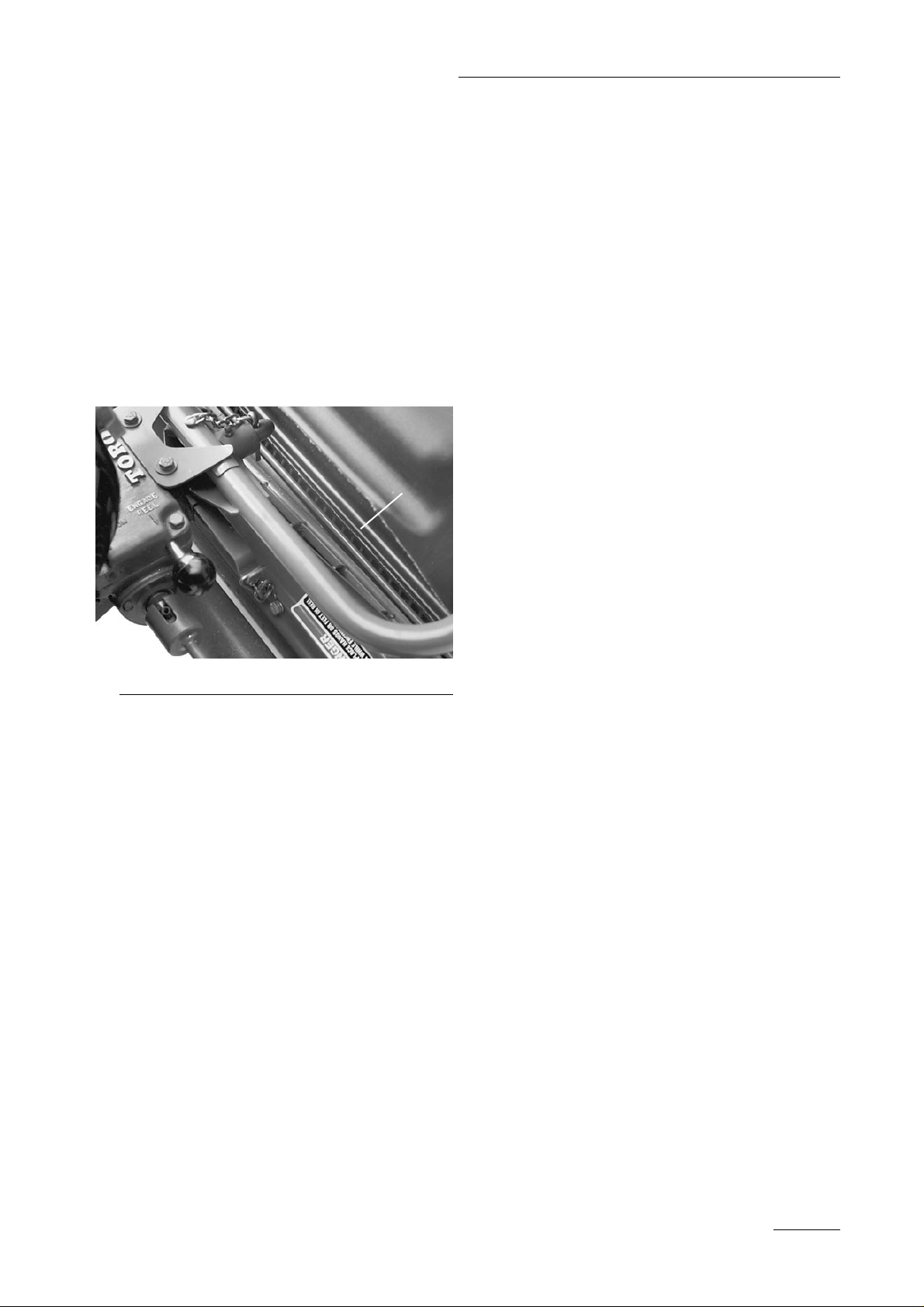
2. Measure the distance between the lip of the
catcher and the edge of the cutting unit shield.
There should be a clearance between the components of no more than 1/4 inch (6 mm) (Fig.
14). If not, adjust the catcher.
Note: The catcher should be lower in front to
assist clipping throw. Adjust the screw to lower
the catcher (Fig. 13). Make sure the catcher
clears the roller by at least 1/16 in. (1.6 mm).
3. Tighten the jam nuts on each side of the catcher
(Fig. 13), making sure the dimension is equal
on both sides of the unit.
Figure 14
1. 1/4 inch (6 mm) maximum
13
Before Operating
1
Page 14
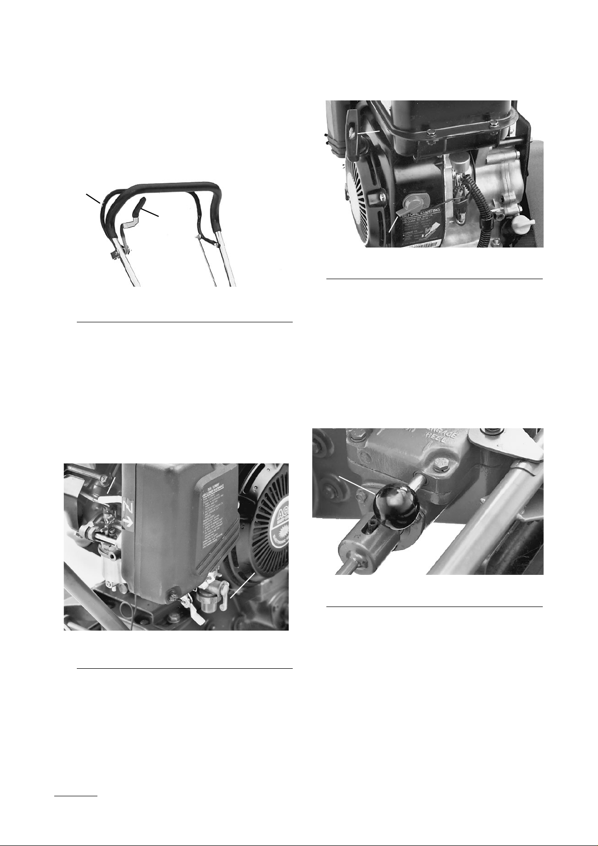
Throttle Control Lever (Fig. 15)—The throttle lever
connects to and operates the throttle linkage to the
carburetor. It has two positions: SLOW and FAST.
Engine speed can be varied between the two settings.
Figure 15
1. Throttle control lever
2. Clutch control bail
Clutch Control Bail (Fig. 15)—The clutch bail con-
trols traction and cutting unit drive. It has two positions: ENGAGE and DISENGAGE.
Choke Lever (Fig. 16)—Located at rear of engine.
It has two positions: RUN and CHOKE. Move the
lever to the CHOKE position when starting a cold
engine. After engine start,s move the lever to the
RUN position.
Figure 16
1. Fuel shut-off valve lever
2. Choke lever
Fuel Shut-off Valve (Fig. 16)—Located at the right
side of the engine, it has two positions: CLOSED
and OPEN. Move the valve lever to the CLOSED
position when storing the machine. Open the valve
before starting the engine.
Figure 17
1. Engine stop switch
2. Recoil starter
Engine Stop Switch (Fig. 17)—Located at the front
of the engine. Rotate to OFF to stop the engine.
Recoil Starter (Fig. 17)—Pull the recoil starter han-
dle to start the engine.
Reel Drive Control (Fig. 18)—Located at right side
transaxle, has two positions: ENGAGE and DISENGAGE. Pull out the knob to engage the reel drive
clutch. Push in the knob to disengage.
Figure 18
1. Reel drive control knob—Pull out to ENGAGE
14
Controls
2
1
2
2
1
1
1
Page 15

STARTING AND STOPPING
INSTRUCTIONS
Note: Make sure the wire is installed on the spark
plug.
1. Assure the traction clutch control bail (Fig. 15)
and the reel drive knob (Fig. 18) are in the
DISENGAGED position.
2. Open the fuel valve at the right side of the
engine (Fig. 16).
3. Turn the engine stop switch to ON (Fig. 17)
4. Only if necessary, move the choke lever (Fig.
16) to the CHOKE position before starting a
cold engine.
Note: A warm or hot engine does
not require any choking. To start a warm
engine, move the throttle control to the mid
throttle position.
5. Stand behind the machine and move the throttle
control lever (Fig. 15( to the mid throttle position. Pull the recoil starter handle out until positive engagement results. Pull the handle to
start the engine and allow the rope to recoil
slowly. If used, open the choke as the engine
warms up.
IMPORTANT: Do not pull the recoil rope to
its limit or let go of the starter handle when
the rope is pulled out because the rope may
break or the recoil assembly may be damaged.
6. To stop the engine during operation, release the
clutch bail to the DISENGAGE position, the
throttle control to SLOW (Fig. 15) and turn the
ON/OFF switch to OFF (Fig. 17).
7. Pull the wire off the spark plug to prevent the
possibility of accidental starting before storing
the machine.
8. Close the fuel valve before storing the machine
(Fig. 16).
TRANSPORT OPERATION
1. Disengage the clutch bail and start the engine.
2. Disengage the cutting unit drive (Fig. 18).
IMPORTANT: Excessive operating of the cut-
ting unit with the absence of any grass clippings (lubricant) can damage the cutting
unit.
3. Place the handle assembly in the uppermost
notch on the handle adjusting bar. Set the throttle control in SLOW, tip the front of the
machine up and slowly increase engine speed
while gradually engaging the clutch control bail
so the mower moves forward slowly.
4. Adjust the throttle to operate the mower at the
desired ground speed and transport the mower
to the desired destination.
BEFORE MOWING
Remove dew and worm casts from turf before mowing by whipping the turf with a bamboo pole or by
dragging a hose over the area. Be sure the
Greensmaster is carefully adjusted and is set evenly
on both sides of the reel. Improper mower adjustment is magnified many times over in the appearance of the clipped turf. Athree- to five-foot wide
(91 to 152 cm) "collar" should be mowed around the
area at a slightly higher cut than the putting green
area. This will provide sufficient space for turning
the Greensmaster without turning on the green area.
METHOD OF MOWING
The greens should be mowed in straight back-andforth direction across the green. Avoid circular
mowing or turning the mower on greens areas since
scuffing may occur. Turning the mower should be
done off the green proper by raising the cutting reel
(pushing the handle down) and turning on the large
rubber-covered traction drums.
The greens areas should not be mowed in the same
direction at any two successive mowings. Cutting in
different directions at each mowing will keep the
grass growing in an upright position, preventing
grain formation.
Mowing should be done at a normal walking pace.
Faster speed saves very little time and will result in
an inferior mowing job.
15
Operation
Page 16
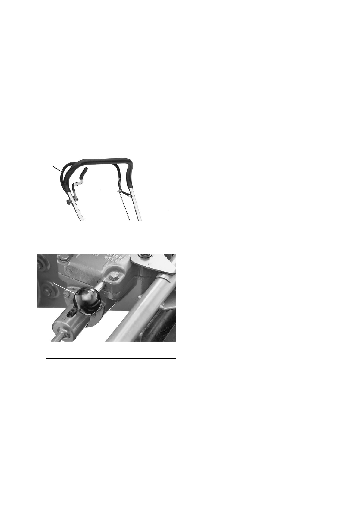
OPERATING CONTROLS
To operate the controls for mowing;
1. Start the engine, push down on the handle to
elevate the cutting unit, raise the traction clutch
bail the handle and transport the machine onto
the collar of the green.
2. Release the traction clutch bail (Fig. 19) to the
DISENGAGE position and pull the reel drive
control knob on the transaxle out fully to
ENGAGE the reel (Fig. 20).
Figure 19
1. Traction clutch control bail
Figure 20
1. Reel drive control knob—Pull out to ENGAGE
3. Raise the clutch control bail to the handle,
increase the throttle speed until the unit is traveling at the desired ground speed, drive the
mower out onto the greens area, drop the front
of the mower down and begin mowing.
AFTER MOWING
1. Drive off the green, release the clutch control
bail to DISENGAGE, stop the engine and push
the reel drive control knob fully in to DISENGAGE.
2. Empty the grass catcher of clippings, install the
grass catcher and begin transport operation;
refer to Transport Operation.
Operating
16
1
1
Page 17

DAILY MAINTENANCE
CHECKLIST
✓ Fuel level
✓ Engine oil level
✓ Air filter pre-cleaner
✓ Clean engine cooling fins
✓ Unusual engine noises
✓ Unusual operating noises
✓ Reel-to-bedknife adjustment
✓ Height-of-cut adjustment
✓ Lubricate control linkage
✓ Lubricate all grease fittings
1
✓ Touch-up damaged paint
1 = Immediately after every washing, regardless of interval listed.
17
Maintenance
Maintenance Procedure Maintenance Interval & Service
✝Initial break in at 10 hours
‡Initial break in at 25 hours
Adjust the reel drive chain
Clean the combustion chamber
Replace the spark plug
Adjust valves and torque the head bolts
Check the spark plug
Service the air cleaner filter
‡Change the engine oil filter
✝Adjust the traction drive belts
Clean the fuel filter and bowl
Check the transmission oil level
Service the air filter foam element
Check for loose fasteners
Lubricate all grease fittings
Every
200 hours
Every
100 hours
Every 50
hours
Every 25
hours
Minimum Recommended Maintenance Intervals
Recommendations:
Adjust the reel drive chain annually.
Page 18
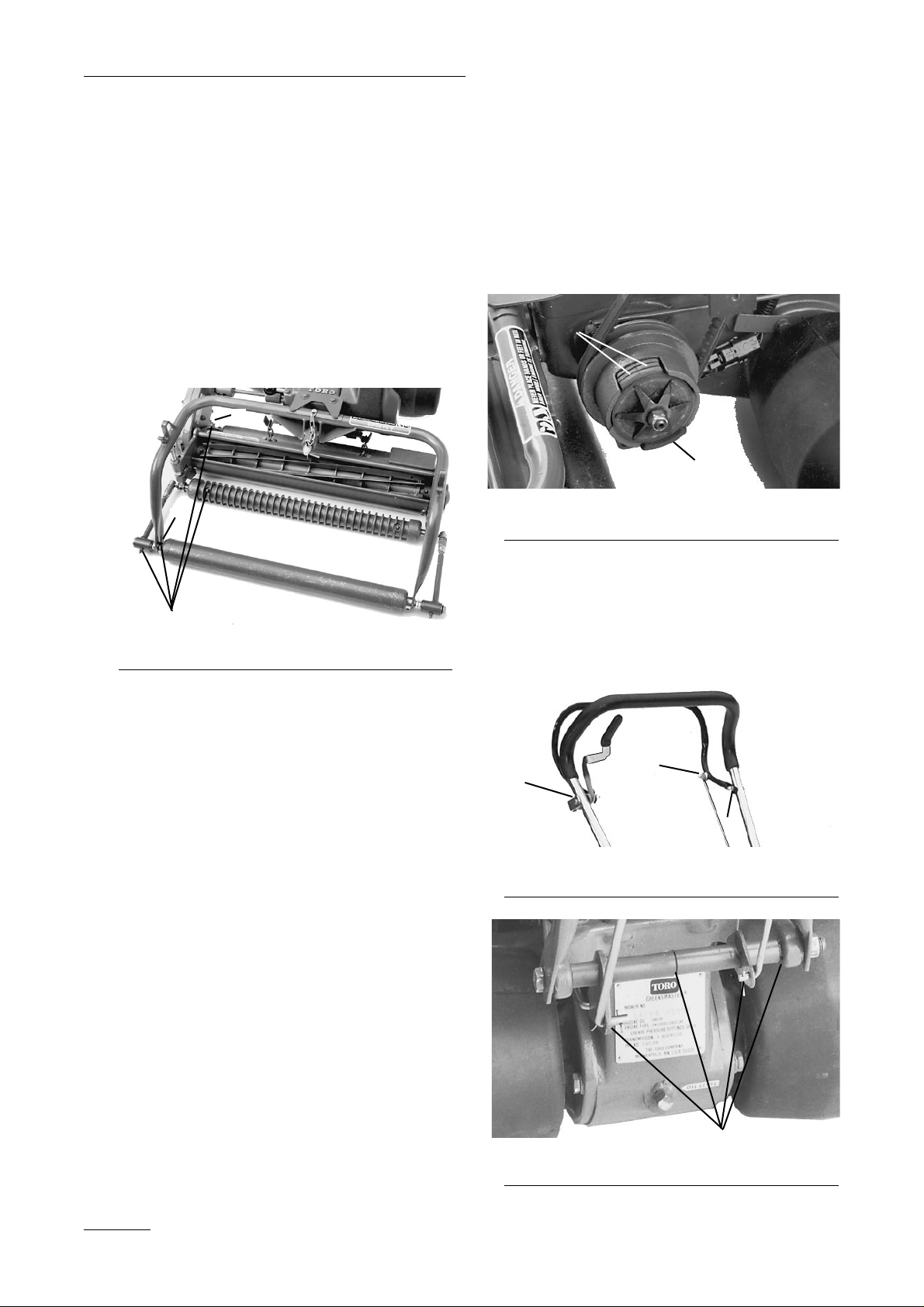
LUBRICATION
GREASE FITTINGS
The grease fittings on the mower should be greased
at least every 25 hours. Lubricate using a No. 2
multi-purpose lithium base grease. Ahand operated
grease gun is recommended for best results.
1. Wipe each grease fitting with a clean cloth.
2. Apply grease to the points shown in Figure 21
Figure 21
1. Grease points
IMPORTANT: Do not apply too much pres-
sure or grease seals will be permanently
damaged.
3. Wipe excess grease away.
GREASING THE TRACTION CLUTCH
1. At the end of each season’s cutting, remove the
traction clutch assembly and clean and re-pack
the cam and roller assembly with No. 5 multipurpose (wheel) bearing grease (Fig. 22). Take
extreme care to make sure that grease is kept
off the clutch friction discs (Fig. 22).
Figure 22
1. Clutch assembly
2. Clutch friction discs
LINKAGE PIVOT POINTS
Oil all pivot points of control linkages weekly with
SAE 30 engine oil (Fig. 23, 24).
Figure 23
1. Oil points
Figure 24
1. Oil points
Maintenance
18
1
1
1
1
2
Page 19
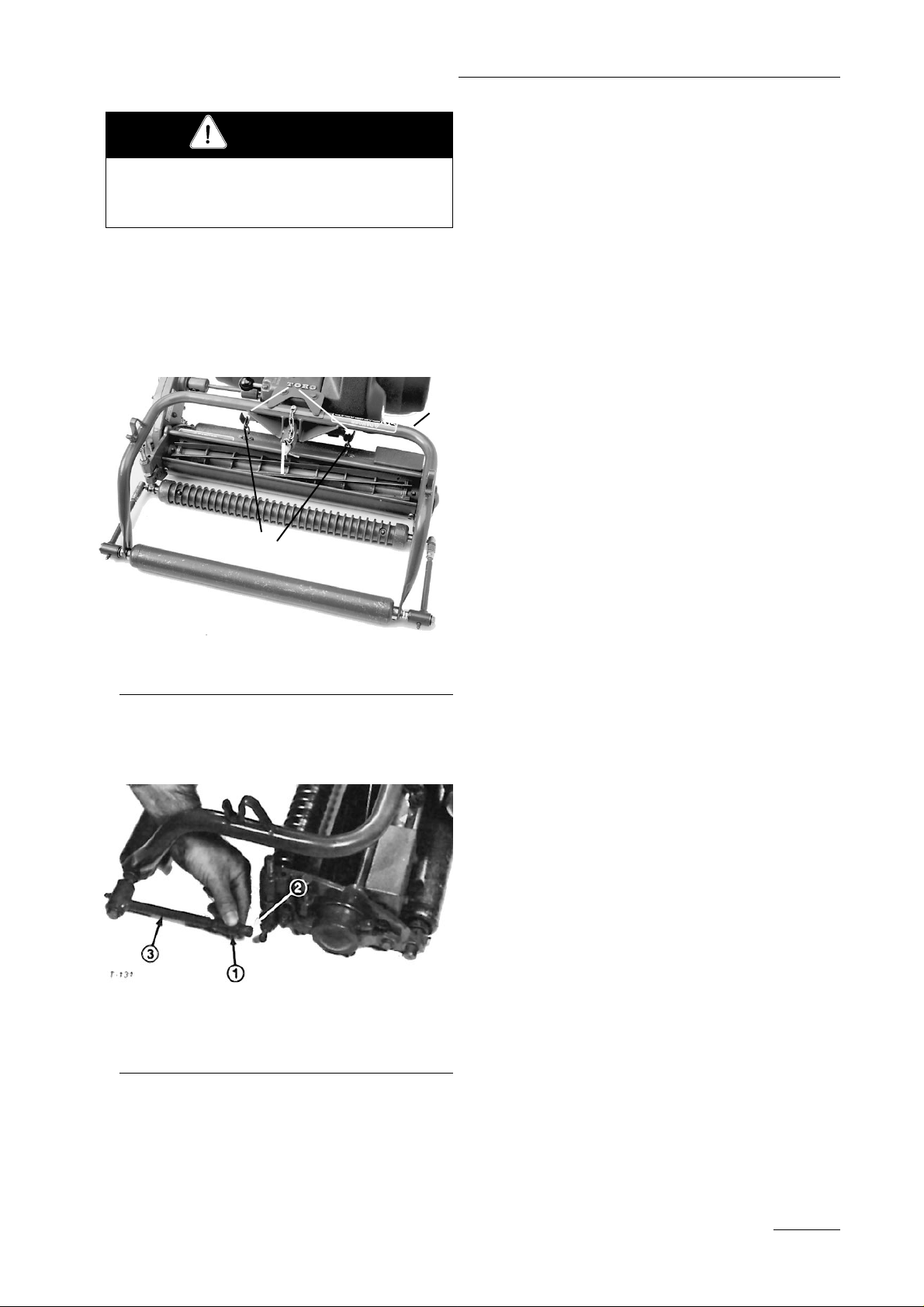
19
Maintenance
REMO VAL AND INSTALLATION
OF CUTTING UNIT
1. Remove the catcher and unhook the two chains
from the support hooks (Fig. 25).
Figure 25
1. Chains 3. Cotter pin
2. Support hooks 4. Yoke pivot
2. Slide the sleeves back on pull arm ball joints
and lift the pull arm sockets straight up off the
ball studs (Fig. 26).
Figure 26
1. Sleeve
2. Pull arm socket
3. Ball stud
3. Grasp the cutting unit chain case and pull the
cutting unit and drive shaft out to the right,
away from the traction unit.
Note: Right and left sides are determined from
behind the handle.
To install the cutting unit:
1. Slide the cutting unit under the yoke from the
right side, line the drive shaft up with the
transaxle shaft and install the drive shaft.
2. Install the chains onto the support hooks
(Fig. 25).
3. Align the pull arms with the ball studs, slide the
sleeves back on the sockets and drop the arm
sockets down on the ball studs (Fig. 26).
4. Make sure the cutting unit is aligned with the
yoke roller and the drive shaft with the
transaxle shaft. If there is misalignment, refer
to Check Cutting Unit Alignment.
REMOVING THE YOKE
ASSEMBLY
To remove the yoke:
1. Remove the catcher and unhook the chains from
the support hooks (Fig. 25).
2. Remove the cotter pin from the yoke pivot and
slide the yoke assembly off the pivot (Fig. 25).
3. Reverse the procedure to install the yoke.
CHANGING ENGINE OIL
1. Run the engine to warm the engine oil.
2. Stop engine, place a drain pan under the plug in
the crankcase on the handle side of the engine,
remove the oil drain plug and allow oil to drain
into the drain pan (Fig. 27).
3. Install the drain plug; remove the oil fill plug
(Fig. 27), assure the engine is level and fill the
crankcase with fresh clean oil; refer to the
Engine Operator's Manual for oil requirements.
Disconnect spark plug wire before performing
any of the maintenance procedures on your
mower.
CAUTION
1
4
2
3
Page 20
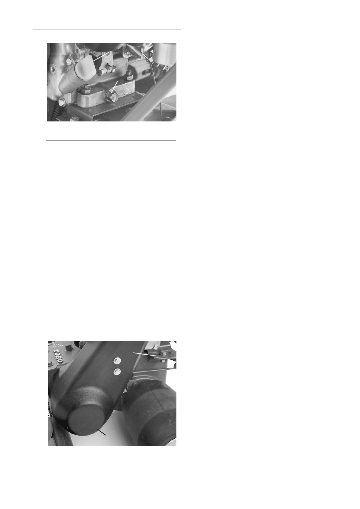
Maintenance
20
Figure 27
1. Oil fill plug
2. Oil drain plug
TRACTION DRIVE BELT
ADJUSTMENT
The belt should be tight enough so the traction
wheels will spin on a cement floor when the clutch
is engaged with the engine running. The belt should
be checked after the first eight hours of operation
and tightened if necessary. To adjust the belt:
1. Remove the belt cover from the left side of the
machine (Fig. 28).
2. Loosen the four engine hold-down screws.
3. Slide the engine rearward equally on both sides
until the belt is tight. Tighten the mounting fasteners and check adjustment by placing the unit
on a cement floor, starting the engine and
checking to see if the traction wheels spin when
the clutch is engaged.
4. Continue adjustment until tension is correct and
install the belt guard (Fig. 28).
Figure 28
1. Cover
2. Engine mounting fastener
BACKLAP OPERATION
Backlap when the reel blades and bedknife edge are
slightly rounded and do not cut the grass cleanly
with a light reel-to-bedknife adjustment. Also backlap after a reel and bedknife have been reground to
assure a perfect match between reel and bedknife
cutting edge.
Backlapping will not correct nicked or severely
rounded reel blades or uneven bedknife wear.
Correct these conditions by repairing, replacing or
re-grinding the components.
1. Using a fine-tooth file, remove high spots from
the reel blades. If a blade is bent, straighten it
by placing a hammer on one side of the blade
and tapping on the opposite side.
2. Make the reel-to-bedknife adjustment to obtain
a light contact; refer to Reel to Bedknife
Adjustment.
3. Connect a lapping machine to the cutting unit
with an extension coupler and socket.
4. Use a good grade of medium grit (80) commer-
cial lapping compound with a water soluble carrier to assure the compound will be easily
washed away after the backlapping operation.
Dry lapping compound should be mixed with
liquid detergent until the material is free flowing.
Note: Paste-type, pre-mixed lapping compound
is also sold in some areas. This is generally
used in its original composition and therefore is
not free flowing.
5. Operate the lapping machine so the reel turns in
a reverse direction for about three minutes;
apply the lapping solution continuously with a
paintbrush across the full width of the reel.
6. Again,, lightly adjust the bedknife and reel.
Then, lap for approximately two additional minutes. Apply lapping solution continuously.
Wash off all lapping solution.
7. Using newspaper, check for sharpness along the
entire length of each reel blade. If the newspaper cannot be cut cleanly along the entire length
of each blade, grinding or re-grinding is neces-
1
2
1
2
Page 21

sary; refer to Reel and Bedknife Grinding.
Note: For a better cutting edge, run a file across
the front face of the bedknife when the lapping
operation is completed. This will remove any
burr or rough edge that may have built up on
the cutting edge.
REEL AND BEDKNIFE
GRINDING
Refer to the TORO GUIDE TO REEL AND
ROTARY MOWER SHARPENING. Copies are
available from your local TORO distributor.
CLEANING THE MOWER
Wash the cutting unit, transaxle, and grass catcher
after each day's use. Chemicals in the turf may cause
premature deterioration to certain components if not
washed daily.
IMPORTANT. Do not direct "high-pressure" water at
oil seals, bearings, electrical connectors/switches, hot
engine, etc.; contamination of these parts could
cause premature wear.
STORAGE
1. Drain gasoline from the fuel tank. Start the
engine and let it run at slow speed until it stops
because all the gasoline is used.
2. Drain the oil from the crankcase: refer to the
Engine Operator's Manual. However, do not fill
the crankcase with oil at this time.
3. Remove grass clippings, dirt and grime from
the external parts of the mower housing and
engine. Also clean the engine cooling system.
4. Clean carbon from the internal parts of the
engine and re-assemble the engine.
5. Pull the wire off the spark plug and clean
around the plug so dirt cannot fall into the
cylinder when the plug is removed. Remove
the plug from the cylinder head and pour two
tablespoons (25 ml) of engine oil into the spark
plug hole. Pull the recoil starter handle slowly
to distribute oil on the inside of the cylinder.
Reinstall the spark plug. If a torque wrench is
not used, tighten the plug firmly. DO NOT
INSTALL THE WIRE ON THE SPARK PLUG.
6. Remove the belt cover over the left side of the
machine. Inspect the belt for excessive wear or
damage., Repair or replace as necessary.
Assure the belt is in the disengaged position.
7. Check the condition of the reel blades and bed-
knife and repair and sharpen them as necessary;
refer to Reel And Bedknife Grinding.
8. Lubricate the mower: refer to Lubrication.
9. Clean the air cleaner.
10. Check and tighten all capscrews, screws, bolts,
nuts and mating parts, If any part is damaged,
repair or replace it.
11. "Touch up" all rusted or chipped paint surfaces.
Make sure to sand affected area before painting.
Note: TORO Re-Kote "touch-up" paint is available
from an authorized Toro service dealer or distributor.
The spray paint dries in minutes to a glossy, factoryfinish.
12. Fill the crankcase with oil: refer to Engine
Operator's Manual.
13. Store the mower in a clean, dry place. Cover the
mower to protect it and keep it clean.
IDENTIFICATION AND
ORDERING
The mower has two identification numbers: a model
number and a serial number. The two numbers are
stamped into a plate located at the rear of the
transaxle case. In any correspondence concerning
the mower, supply the model and serial numbers to
assure that correct information and replacement parts
are obtained.
21
Maintenance
Be careful when lapping the reel because contact with the reel or other moving parts can
result in personal injury.
CAUTION
Page 22

To order replacement parts from an authorized
TORO distributor, supply the following information:
1. Model and serial number of the mower.
2. Part number, description and quantity of part(s)
desired.
Note: Do not order by reference number if a parts
catalog is being used; use the PART NUMBER.
Maintenance
22
Page 23

Page 24

 Loading...