

Page 1
PART NO. 03124SL (Rev. C)
Service Manual
(Models 41229 and 41235)
Workman
Preface
The purpose of this publication is to provide the service
technician with information for troubleshooting, testing,
and repair of major systems and components on the
Workman 200 Spray System (Models 41229 and
41235).
REFER TO THE OPERATOR’S MANUAL FOR OPERATING, MAINTENANCE, AND ADJUSTMENT
INSTRUCTIONS. Keep the Operator’s Manual, Installation Instructions and Parts Catalog for your machine
with this Service Manual. Replacement Operator’s
Manuals and Parts Catalogs are available on the internet at www.Toro.com.
The T oroCompany reserves the right to change product
specifications or this publication without notice.
R
200 Spray System
This safety symbol means DANGER, WARNING,
or CAUTION, PERSONAL SAFETY INSTRUCTION. When you see this symbol, carefully read
the instructions that follow. Failure to obey the
instructions may result in personal injury.
NOTE: A NOTE will give general information about the
correct operation, maintenance, service, testing, or repair of the machine.
IMPORTANT: The IMPORTANT notice will give important instructions which must be followed to prevent damage to systems or components on the
machine.
E The Toro Company -- 2003, 2005, 2011, 2014
Page 2

This page is intentionally blank.
Workman 200 Spray System
Page 3

Table Of Contents
Chapter 1 -- Safety and Product Records
Safety Instructions 1 -- 2..........................
Safety and Instruction Decals 1 -- 3................
Product Records 1 -- 3...........................
Chapter 2 -- Electrical System
Electrical Schematic and Electrical Harness and Con-
nector Drawings 2 -- 2..........................
Special Tools 2 -- 3..............................
Component Testing 2 -- 4.........................
Chapter 3 -- Spray System
Specifications 3 -- 2..............................
General Information 3 -- 3........................
Spray System Flow Diagram 3 -- 4.................
Spray System Operation 3 -- 5....................
Troubleshooting 3 -- 6............................
Service and Repairs 3 -- 8........................
Chapter 3.1 -- Sonic Boom System (Optional Kit)
General Information 3.1 -- 2......................
Special Tools 3.1 -- 3............................
Electrical Schematic 3.1 -- 4......................
Sonic Boom System Operation 3.1 -- 6.............
Troubleshooting 3.1 -- 16.........................
Service and Repairs 3.1 -- 22.....................
Chapter 3.2 -- Ultra Sonic Boom System (Optional
Kit)
Safety andElectrical
System
Spray
System
System
Sonic Boom
Product Records
General Information 3.2 -- 2......................
Special Tools 3.2 -- 3............................
Electrical Schematic 3.2 -- 4......................
Sonic Boom System Operation 3.2 -- 6.............
Troubleshooting 3.2 -- 17.........................
Service and Repairs 3.2 -- 26.....................
Chapter 4 -- Electrical Diagrams
Electrical Schematics 4 -- 3.......................
Wire Harness Drawings 4 -- 6.....................
Ultra Sonic
Boom System
Electrical
Diagrams
Workman 200 Spray System
Rev. C
Page 4

This page is intentionally blank.
Workman 200 Spray System
Page 5

Safety and Product Records
Table of Contents
SAFETY INSTRUCTIONS . . . . . . . . . . . . . . . . . . . . . . 2
Before Operating . . . . . . . . . . . . . . . . . . . . . . . . . . . . 2
While Operating . . . . . . . . . . . . . . . . . . . . . . . . . . . . . 2
Maintenance and Service . . . . . . . . . . . . . . . . . . . . 3
SAFETY AND INSTRUCTION DECALS . . . . . . . . . . 3
PRODUCT RECORDS . . . . . . . . . . . . . . . . . . . . . . . . . 3
Chapter 1
Safety and
Product Records
Workman 200 Spray System Page 1 – 1 Safety and Product Records
Page 6

Safety Instructions
The Workman 200 Spray System is designed and
tested to offer safe service when operated and maintained properly . Although hazard control and accident
prevention are partially dependent upon the design and
configuration of the machine, these factors are also dependent upon the awareness, concern, and proper
training of the personnel involved in the operation, transport, maintenance, and storage of the machine. Improper use or maintenance of the machine can result in injury
or death. To reduce the potential for injury or death,
comply with the following safety instructions.
Before Op erating
WARNING
To reduce the potential for injury or death,comply with the following safety instructions.
1. Read and understand the contents of the Operator’s
Manual before starting and operating the machine. Become familiar with the controls and know how to stop the
machine and engine quickly. A replacement Operator’s
Manual is available on the Internet at www.Toro.com.
While Operating
1. Sit on the seat when starting and operating the machine.
2. Before starting the engine:
A. Engage the parking brake.
B. Make sure drive system is in the NEUTRAL position and the pump switch is OFF.
3. Do not run engine in a confined area without adequate ventilation. Exhaust fumes are hazardous and
could possibly be deadly.
4. Do not touch engine, radiator, muffler or exhaust
pipe while engine is running or soon after it is stopped.
These areas could be hot enough to cause burns.
2. Keep all shields, safety devices, and decals in place.
If a shield, safety device, or decal is defective, illegible
or damaged, repair or replace it before operating the
machine. Also tighten any loose nuts, bolts or screws to
ensure machine is in safe operating condition.
5. Before getting off the seat:
A. Ensure that drive system is in the NEUTRAL
position.
B. Set parking brake.
C. Turn pump switch OFF.
D. Stop engine and remove key from ignition switch.
E. Do not park on slopes unless wheels are chocked
or blocked.
6. Follow spray chemical manufacturer ’s recommendations for handling precautions, protective equipment,
and mixing proportions.
Rev. B
Workman 200 Spray SystemPage 1 -- 2Safety and Product Records
Page 7

Maintenance and Service
1. Before servicing or making adjustments, turn PTO
off, put shift lever in neutral, stop engine, set parking
brake, and remove key from the switch.
2. Prior to servicing sprayer components, determine
what chemical(s) have been used in the sprayer. Follow
precautions and recommendations printed on chemical
container labels or Material Safety Data Sheets when
servicing sprayer components. Use appropriate protec
tive equipment: protective clothing, chemical resistant
gloves, and eye protection.
3. Make sure machine is in safe operating condition by
keeping all nuts, bolts and screws tight.
4. Never store the machine or fuel container inside
where there is an open flame, such as near a water heat
er or furnace.
5. If major repairs are ever needed or assistance is desired, contact an Authorized Toro Distributor.
6. If engine must be running to perform maintenance or
an adjustment, keep clothing, hands, feet, and other
parts of the body away from moving parts. Keep by
standers away.
-
-
-
7. Disconnect battery before servicing the machine.
Disconnect negative (–) battery cable first and positive
(+) cable last. If battery voltage is required for troubleshooting or test procedures, temporarily connect the
battery. Reconnect positive (+) cable first and negative
(–) cable last.
8. Battery acid is poisonous and can cause burns.
Avoid contact with skin, eyes, and clothing. Protect your
face, eyes, and clothing when working with a battery.
9. Battery gases can explode. Keep cigarettes, sparks,
and flames away from the battery.
10.To assure optimum performance and continued
safety of the machine, use genuine Toro replacement
parts and accessories. Replacement parts and acces
sories made by other manufacturers may result in nonconformance with safety standards, and the warranty
may be voided.
-
Safety and
Product Records
Safety and Instruction Decals
Numerous safety and instruction decals are affixed to
the Workman 200 Spray System. If any decal becomes
illegible or damaged, install a new decal. Part numbers
are listed in your Parts Catalog. Order replacement decals from your Authorized Toro Distributor.
Product Records
Insert Operator’s Manual, Installation Instructions and
Parts Catalog for your Workman 200 Spray System at
the end of this Chapter. Refer to Operator’s Manual for
recommended maintenance intervals. Additionally, in
sert Installation Instructions, Operator’s Manuals, and
Parts Catalogs for other accessories (e.g. Foam Mark
ing Kit, Hose Reel Kit) that have been installed on your
Workman vehicle at the end of this Chapter.
-
-
Workman 200 Spray System Page 1 – 3 Safety and Product Records
Page 8

This page is intentionally blank.
Safety and Product Records Page 1 – 4 Workman 200 Spray System
Page 9

Table of Contents
ELECTRICAL SCHEMATIC and ELECTRICAL
HARNESS and CONNECTOR DRAWINGS 2.....
SPECIAL TOOLS 3.............................
COMPONENT TESTING 4.......................
Master Boom Switch 4.........................
Rate Control and Boom Actuator Switches 5......
Supervisor Key Switch 6.......................
Boom Control and Monitor Power Switches 7.....
Hold and Boom Actuator (Serial Numbers
Above 260000000) Relays 8..................
Traction Speed Sensor 9.......................
Chapter 2
Electrical System
System
Electrical
Workman 200 Spray System Page 2 -- 1 Electrical System
Rev. B
Page 10

Electrical Schematic and Electrical Harness and
Connector Drawings
The electrical schematic and other electrical drawings
for the Workman 200 Spray System are located in Chap
ter 4 – Electrical Diagrams.
-
Electrical System
Page 2 – 2
Workman 200 Spray System
Page 11
Special Tools
Multimeter
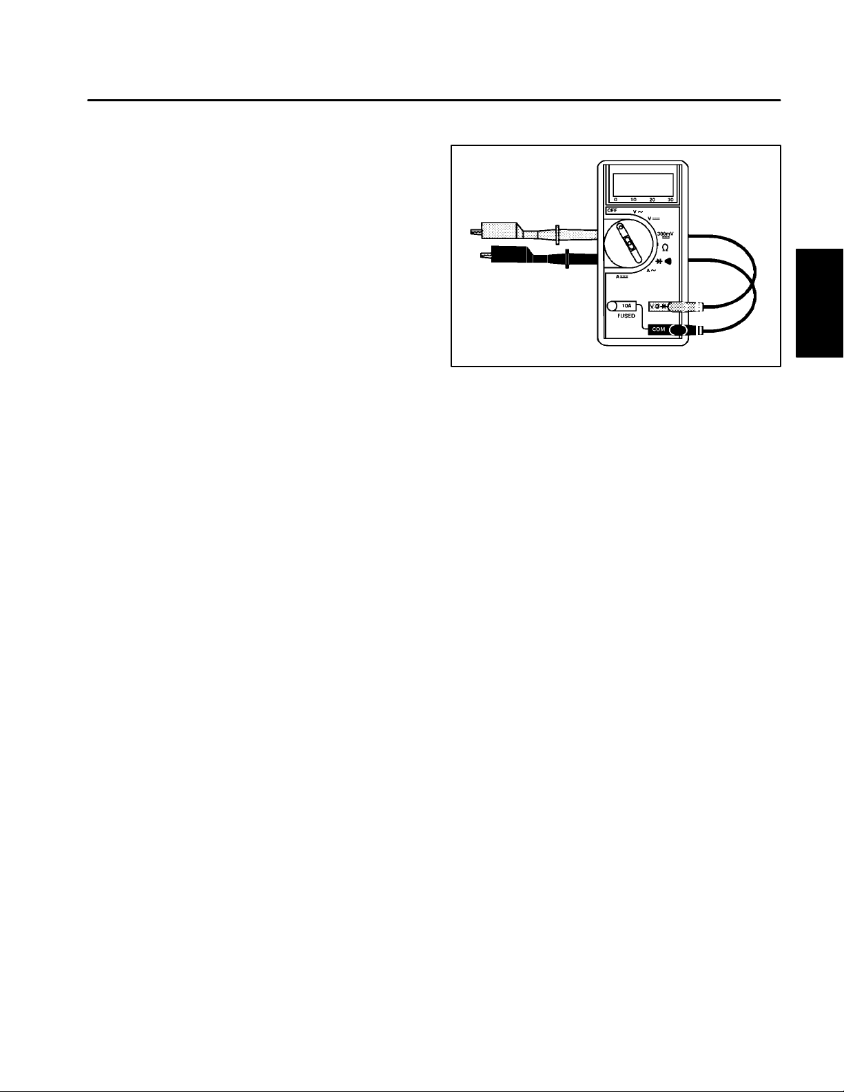
The multimeter can test electrical components and circuits for current, resistance, or voltage.
NOTE: Toro recommends the use of a DIGITAL Volt–
Ohm–Amp multimeter when testing electrical circuits.
The high impedance (internal resistance) of a digital me
ter in the voltage mode will make sure that excess current is not allowed through the meter. This excess
current can cause damage to circuits not designed to
carry it.
-
Figure 1
System
Electrical
Workman 200 Spray System
Page 2 – 3
Electrical System
Page 12
Component Testing
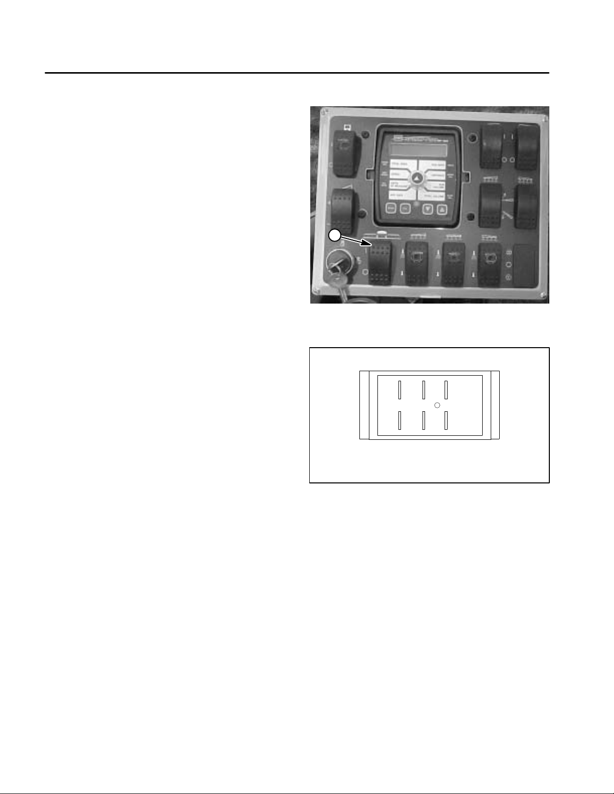
Master Boom Switch
The master boom switch is located on the spray control
enclosure faceplate (Fig. 2).
Testing
1. Remove spray control enclosure faceplate, locate
master boom switch and unplug wire harness connector
from switch.
2. The switch terminals are marked as shown in Figure
3. In the ON position, continuity should exist between
terminals 2 and 3 and also between terminals 5 and 6.
In the OFF position, continuity should exist between ter
minals 1 and 2 and also between terminals 4 and 5.
3. Reconnect the harness connectors to the switch after testing. Install console panel to machine.
1
-
Figure 2
1. Master boom switch
4 5 6
1 2 3
BACK OF SWITCH
Figure 3
Electrical System
Page 2 – 4
Workman 200 Spray System
Page 13
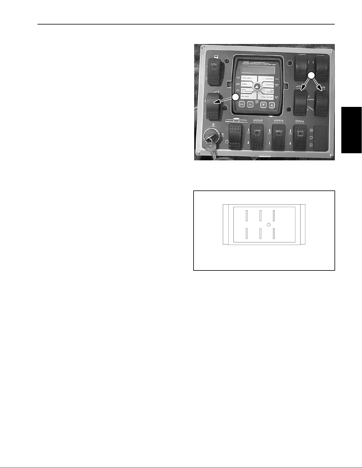
Rate Control and Boom Actuator Switches
The rate control (increase/decrease) switch is located
on the spray control enclosure faceplate (Fig. 4).
On machines equipped with the electric boom lift, this is
the same switch that is used to operate the boom actuators.
2
Testing
1. Remove spray control enclosure faceplate, locate
switch to be tested and unplug wire harness connector
from switch.
2. The switch terminals are marked as shown in Figure
5. In the INCREASE or boom raise position, continuity
should exist between terminals 2 and 3 and also between terminals 5 and 6. In the neutral, center position,
there should be no continuity between any switch terminals. In the DECREASE or boom lower position, continuity should exist between terminals 2 and 1 and also
between terminals 5 and 4.
3. Reconnect the harness connector to the switch after
testing. Install console panel to machine.
1
Figure 4
1. Rate control switch
2. Boom actuator switch
56
1243
BACK OF SWITCH
System
Electrical
Figure 5
Workman 200 Spray System Page 2 -- 5 Electrical System
Rev. B
Page 14
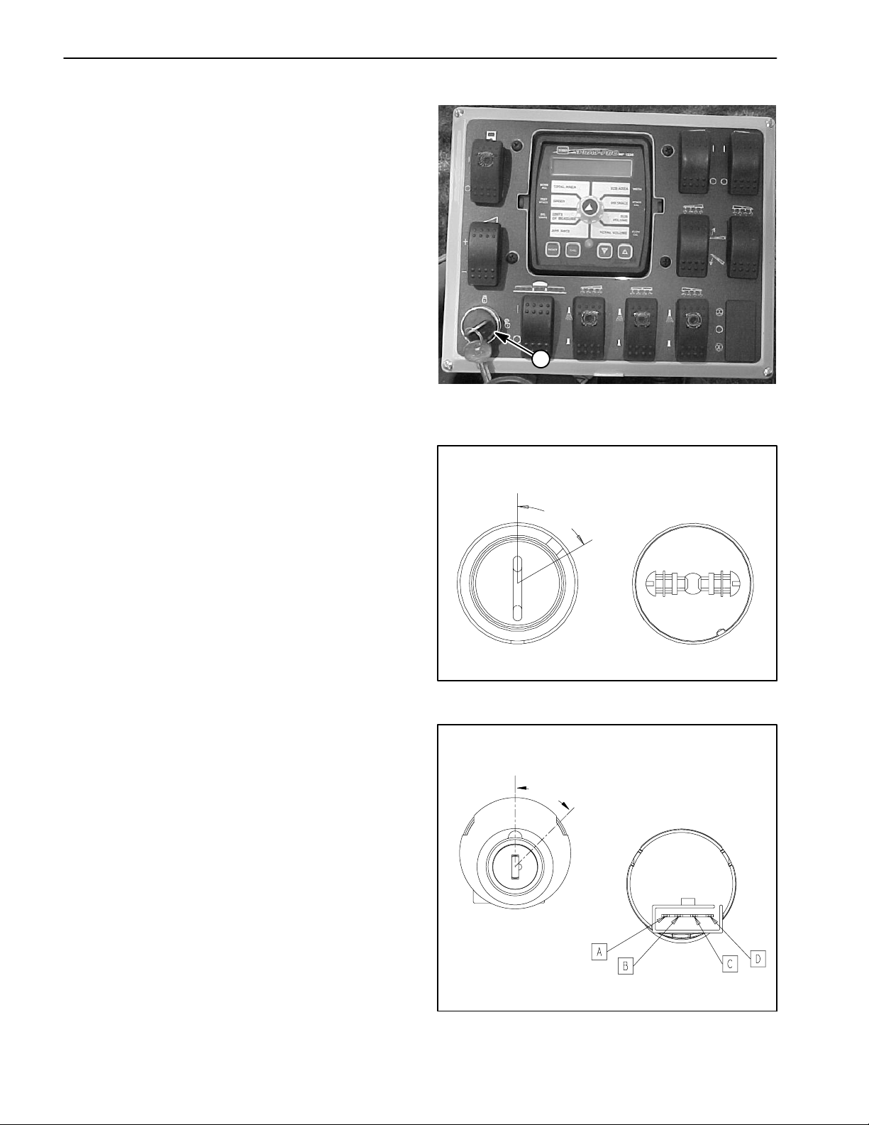
Supervisor Key Switch
The supervisor key switch (rate lockout) is located on
the spray control enclosure faceplate (Fig. 6). When the
supervisor key switch is in the OFF (locked) position, the
application rate switch is disabled.
The supervisor key switch used on sprayers with serial
numbers below 270000000 is shown in Figure 7. The
key switch used on s prayers with serial numbers above
270000000 is shown in Figure 8.
Testing
1. Remove spray control enclosure faceplate, locate
supervisor k ey switch and removewire harness connectors from switch.
2. Test switch for continuity as follows:
A. For sprayers with serial numbers below
270000000 (Fig. 7), when the key is in the ON position, continuity should exist between the two switch
terminals. In the OFF position, there should be no
continuity between the switch terminals.
B. For sprayers with serial numbers above
270000000 (Fig. 8), when the key is in the ON position, continuity should exist between switch terminals A and D. In the OFF position, there should be no
continuity between switch terminals A and D. Switch
terminals B and C are not used on the Workman 200
sprayer.
1
Figure 6
1. Supervisor key switch
SERIAL NUMBER BELOW 270000000
OFF
o
60
ON
3. Reconnect the harness connectors to the switch after testing. Install console panel to machine.
FRONTOFSWITCH
BACK OF SWITCH
Figure 7
SERIAL NUMBER ABOVE 270000000
OFF (LOCKED)
o
45
ON (UNLOCKED)
FRONTOFSWITCH
BACK OF SWITCH
Figure 8
Rev. B
Workman 200 Spray SystemPage 2 -- 6Electrical System
Page 15
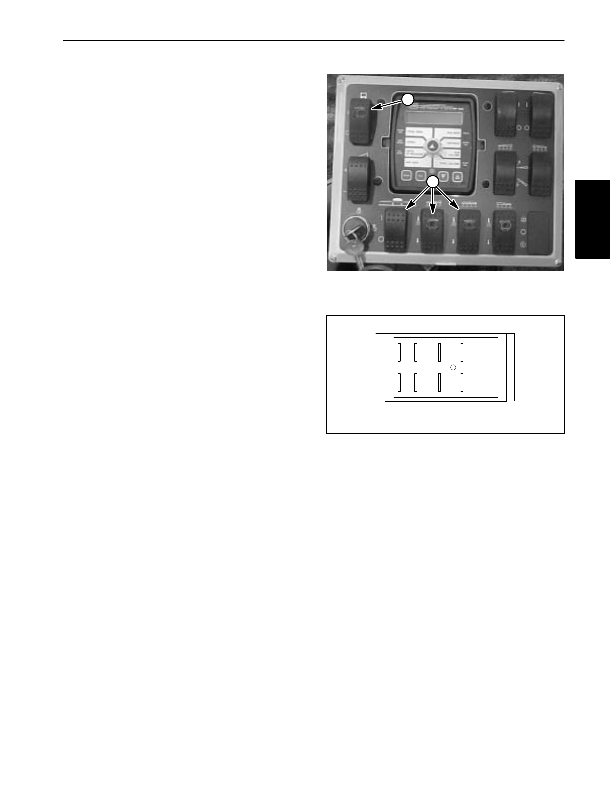
Boom Control and Monitor Power Switches
The three boom control (on/off) and monitor power
switches are located on the spray control enclosure
faceplate (Fig. 8).
Testing
1. Remove spray control enclosure faceplate, locate
boom control switch and unplug wire harness connector
from switch.
2. The switch terminals are marked as shown in Figure
9. In the ON position, continuity should exist between
terminals 2 and 3 and also between terminals 5 and 6.
In the OFF position, continuity should exist between ter
minals 1 and 2 and also between terminals 4 and 5.
3. Terminals 7 (–) and 8 (+) are used for the indicator
light in the switch. The light should be illuminated when
the switch is in the ON position.
4. Reconnect the harness connector to the switch after
testing. Install console panel to machine.
-
2
1
Figure 8
1. Boom control switch 2. Monitor power switch
7 4 5 6
System
Electrical
8 1 2 3
BACK OF SWITCH
Figure 9
Workman 200 Spray System
Page 2 – 7
Electrical System
Page 16
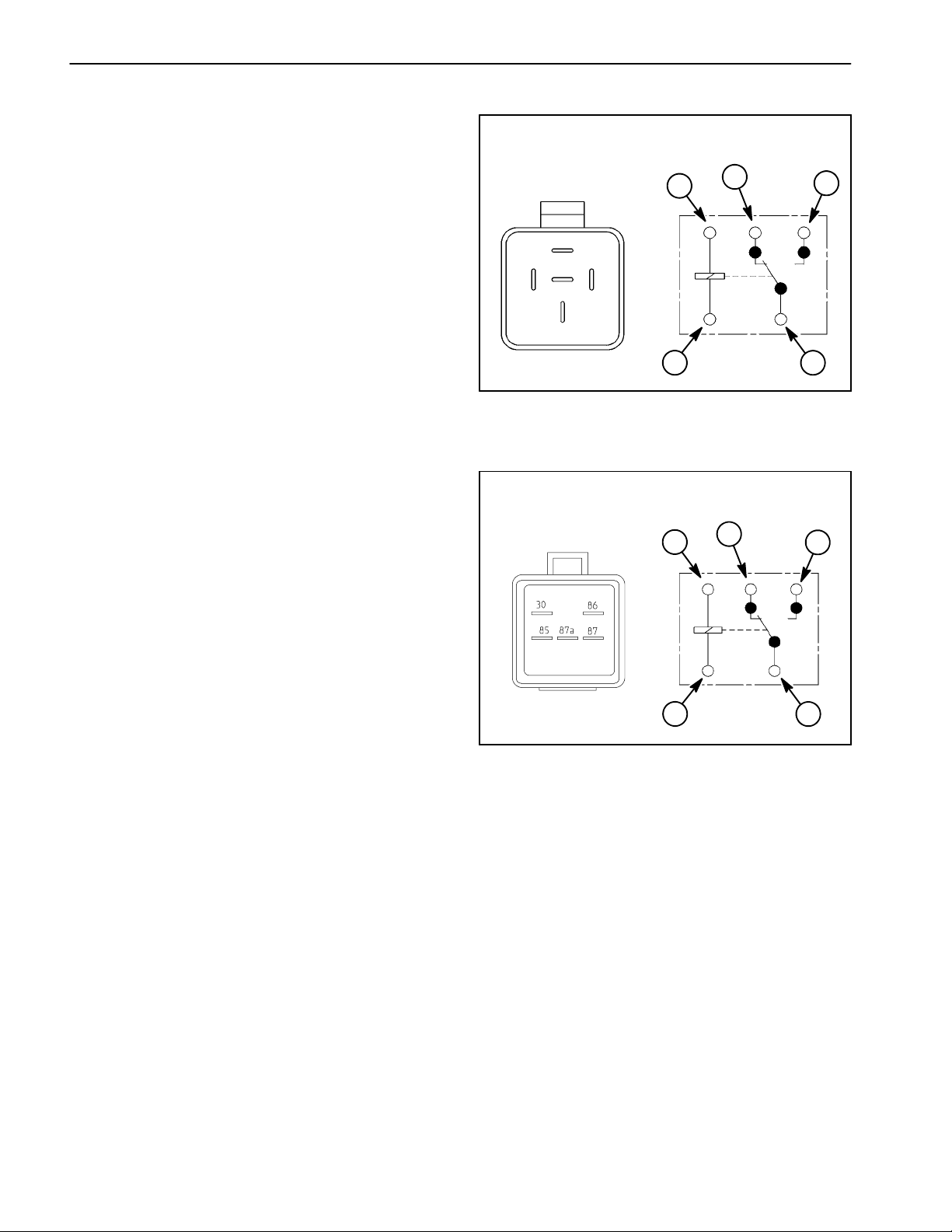
Hold and Boom Actuator (Serial Numbers Above 260000000) Relays
Workman sprayers with serial numbers below
260000000 use a single relay for the sprayer hold function. Sprayers with serial numbers above 260000000
use the hold relay and four (4) additional relays for the
boom actuators. The hold and boom actuator relays are
located in the spray control enclosure.The relays can be
identified by a tag at the relay wire harness connector.
SERIAL NUMBER BELOW 260000000
87
1
3
868587A 87
4
The relay used on sprayers with serial numbers below
260000000 (Fig. 11) has a different terminal layout than
relays used on sprayers with serial numbers above
260000000 (Fig. 12). Relay operation and circuit logic is
the same regardless of serial number.
Testing
1. Remove spray control enclosure faceplate, locate
relay that is to be tested and unplug wire harness connector from relay.
2. Connect multimeter (ohms setting) leads to relay terminals 30 and 87. Ground terminal 86 and apply +12
VDC to terminal 85. The relay should make and break
continuity between terminals 30 and 87 as +12 VDC is
applied and removed from terminal 85.
3. Disconnect voltage from terminal 85 and multimeter
lead from terminal 87.
4. Connect multimeter (ohms setting) leads to relay terminals 30 and 87A. Apply +12 VDC to terminal 85. The
relay should make and break continuity between terminals 30 and 87A as +12 VDC is applied and removed
from terminal 85.
87A
86
85
30
1
Figure 11
1. Coil terminal
2. Common terminal
3. Normally closed term.
4. Normally open term.
SERIAL NUMBER ABOVE 260000000
1
868587A 87
1
30
2
3
30
4
2
5. Disconnect voltage and multimeter leads from the
relay terminals. Reconnect relay to machine wire harness and install spray control enclosure faceplate.
1. Coil terminal
2. Common terminal
Rev. B
Figure 12
3. Normally closed term.
4. Normally open term.
Workman 200 Spray SystemPage 2 -- 8Electrical System
Page 17
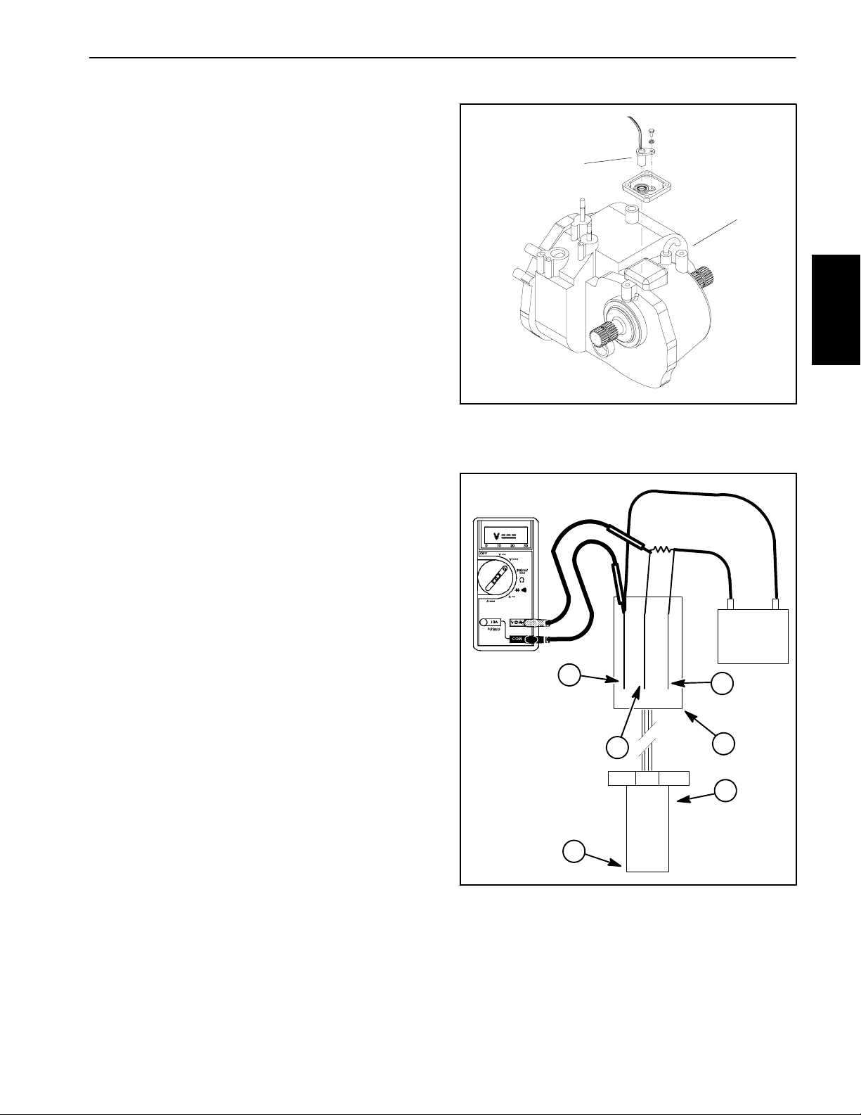
Traction Speed Sensor
The traction speed sensor is attached to the upper
transaxle cover (Fig. 13). It uses a magnetically based,
Hall Effect integrated circuit. As the differential in the
transaxle turns, the sensor accurately senses the movement of the differential ring gear teeth passing by the
sensor. The red striped connector wire is the positive
lead, the black wire is the ground lead, and the gray
striped wire is the signal output.
Testing
6. Locate traction speed sensor on the transaxle assembly. Disconnect the wire harness connector from the
traction speed sensor.
7. Remove cap screw and lock washer that secure
speed sensor to transaxle. Remove speed sensor from
transaxle.
2
1
System
Electrical
8. Connect positive multimeter test lead to the sensor
connector gray striped wire terminal and the negative
multimeter lead to the connector black wire terminal
(Fig. 14). Set multimeter to ohms setting.
IMPORTANT: Incorrect jumper wire connections
during testing can damage the sensor.
9. Using a +12 VDC battery, a multimeter, a 1K ohm resistor and appropriate jumper wires, connect the battery
and multimeter to the speed sensor using Figure 14 as
a guide.
10.Set multimeter to DC volts setting.
11. The multimeter should display very low voltage when
a metal object is held near the sensor tip. The multimeter
should display battery voltage when the metal object is
moved away from the sensor tip.
12.After testing is complete, remove jumper wires, resistor and multimeter leads from sensor connector.
13.Replace speed sensor if necessary.
14.After testing is complete, remove jumper wires and
multimeter leads from sensor connector. Reinstall
speed sensor into transaxle and secure with cap screw
and lock washer. Reconnect speed sensor to wire harness.
Figure 13
1. Transaxle assembly 2. Traction speed sensor
1K ohm
resistor
+
12 VDC
6
4
BAC
5
3
1
2
Figure 14
1. Speed sensor
2. Sensor tip
3. Sensor connector
4. Red striped wire
5. Gray striped wire
6. Black wire
--
Workman 200 Spray System Page 2 -- 9 Electrical System
Rev. B
Page 18

This page is intentionally blank.
Electrical System
Page 2 – 10
Workman 200 Spray System
Page 19

Table of Contents
Chapter 3
Spray System
SPECIFICATIONS 2.............................
GENERAL INFORMATION 3.....................
Precautions Concerning Chemicals Used in
Spray System 3.............................
Precautions for Removing or Adjusting Spray
System Components 3.......................
O--Ring Seal Kit 3.............................
SPRAY SYSTEM FLOW DIAGRAM 4..............
SPRAY SYSTEM OPERATION 5..................
TROUBLESHOOTING 6.........................
SERVICE AND REPAIRS 8......................
Suction Dampener 8..........................
Pressure Dampener 9.........................
Spray Pump 10...............................
Spray Pump Service 12........................
Agitation Control Valve 16......................
Agitation Nozzles (Tank Mounted) 18............
Pressure Relief Valve (Tank Mounted) 20.........
Spray Control (Serial Numbers Below
290999999) 22..............................
Spray Control (Serial Numbers Above
310000000) 23.1............................
Flowmeter (Serial Numbers Below 290999999) 24.
Flowmeter (Serial Numbers Above 310000000)25.1
Rate Control Motor (Serial Numbers Below
290999999) 26..............................
Regulating Valve Assembly (Serial Numbers
Above 310000000) 27.1.....................
Boom Valve Motor (Serial Numbers Below
290999999) 28..............................
Boom Valve Manifold Assembly (Serial Numbers
Above 310000000) 31.1.....................
Boom Bypass 32..............................
Tank Suction 34..............................
Tank Drain 36................................
Turret Bodies 38..............................
Turret Body Service 39........................
Boom Frame Breakaway Pivot Assembly
(Machines with Serial Numbers Below
260000000) 40..............................
Boom Hinge (Machines with Serial Numbers
Above 260000000) 42.......................
Boom Actuator (Optional) (Machines with
Serial Numbers Below 260000000) 44.........
Boom Actuator Service (Machines with Serial
Numbers Below 260000000) 46...............
Boom Actuator (Machines with Serial Numbers
Above 260000000) 48.......................
Boom Actuator Service (Machines with Serial
Numbers Above 260000000) 50...............
Spray
System
Workman 200 Spray System Page 3 -- 1 Spray System
Rev. B
Page 20

Specifications
Item Description
Spray Pump Diaphragm Pump, 29 GPM
Spray Pressure Relief Valve Poppet Style, 220 PSI Maximum
Sprayer Tank 200 Gallon (757 Liter), Polyethylene
Suction Strainer 50 Mesh, Stainless Steel, Tank Mounted
(30 Mesh and 90 Mesh Optional)
Spray System
Page 3 – 2
Workman 200 Spray System
Page 21
General Information
Precautions Concerning Chemicals Used in Spray System
Chemicals can injure persons, animals, plants, soil, or
other property. To eliminate environmental damage and
personal injury:
1. Select the proper chemical for the job.
2. Carefully read the directions printed on the chemical
manufacturer’s labels before handling chemicals. Instructions on chemical manufacturer’s container labels
regarding mixing proportions should be read and strictly
followed.
3. Keep spray material away from skin. If spray material
comes in contact with a person, wash it off immediately
in accordance with manufacturer’s recommendations
(container labels and Material Safety Data Sheets).
4. Always wear protective clothing, chemical resistant
gloves, eye protection, and other personal protective
equipment as recommended by the chemical manufacturer.
5. Properly dispose of chemical containers, unused
chemicals, and chemical solution.
Precautions for Removing or Adjusting Spray System Components
1. Stop the vehicle and set the parking brake.
2. Shut off the vehicle’s engine and remove the key
from the ignition switch.
3. Disengage all power and wait until all moving parts
have stopped.
4. Remove chemicals from pump, hoses, and other
spray components. Thoroughly neutralize and rinse
spray system before loosening or removing any spray
system component(s).
5. Make sure line pressure is relieved before loosening
any system component.
Spray
System
O--Ring Seal Kit (Serial Numbers Below 310000000)
Part Number: 106 --4846
The O--Ring Seal Kit includes an assortment of O--rings
used for sealing the spray c ontrol valves on Workman
sprayers with serial numbers below 310000000. It is
recommended that O--rings be replaced every two (2)
years or whenever a valve is loosened.
SPRAYER
O--RING SEAL KIT
PART NO. 106--4846
Figure 1
Workman 200 Spray System Page 3 -- 3 Spray System
Rev. B
Page 22
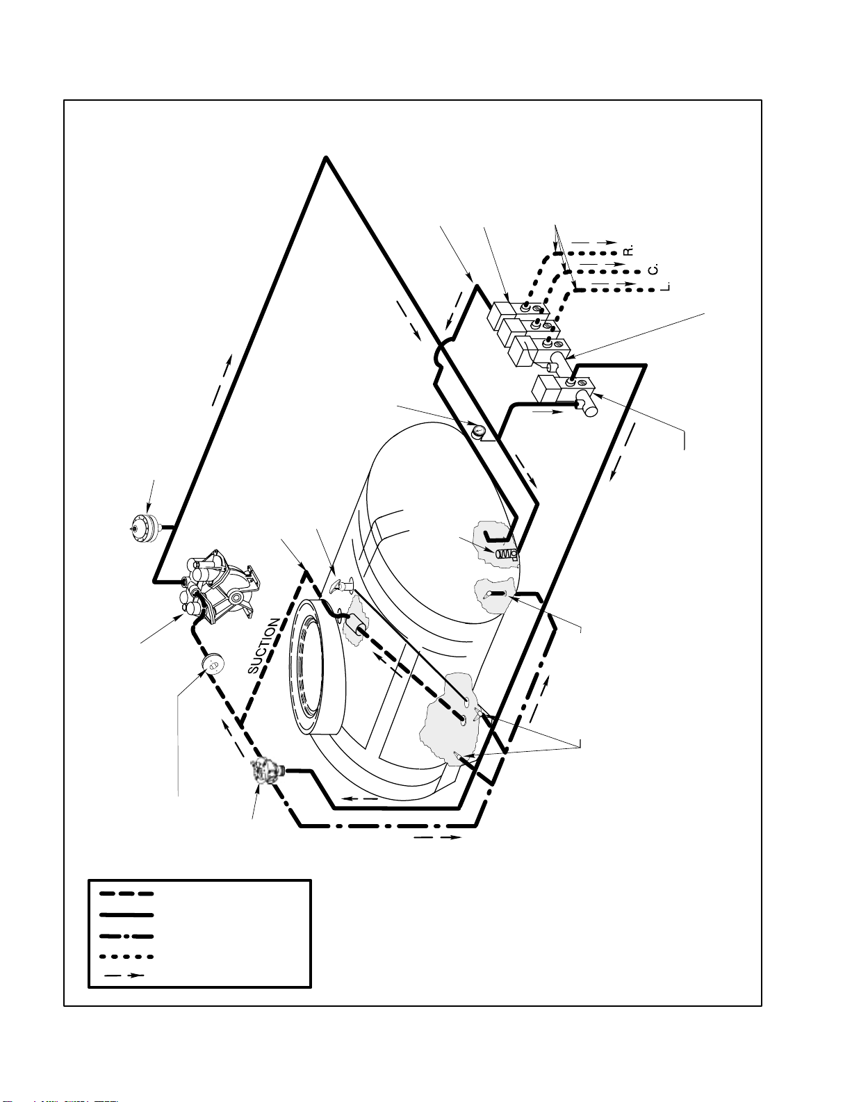
Spray System Flow Diagram
PRESSURE
PRESSURE DAMPENER
& SCREEN
TOP MOUNTED SUCTION
TOP MOUNTED TANK
DRAIN VALVE
BOOM BY–PASS
PRESSURE
GAUGE
PRESSURE
RELIEF
BOOM CONTROL
VALVES
VALVE
BOOM SUPPLY
PRESSURE
FLOWMETER
PRESSURE CONTROL
VALVE
DIAPHRAGM PUMP
CONNECTED TO PTO
Spray System
SUCTION
DAMPENER
SUCTION
PRESSURE
AGITATION
BOOM SUPPLY
FLOW DIRECTION
CONTROL
AGITATION
VALVE
TANK
AGITATION
Page 3 – 4
AGITATORS (4)
Workman 200 Spray System
Spray System Flow Diagram
Workman 200 Spray System
Page 23

Spray System Operation
The Workman 200 Spray System uses a positive displacement diaphragm pump to move spray solution
from the spray tank to the boom nozzles. The spray
pump is self–priming and has a dry crankcase. The
pump is driven by the transaxle PTO kit output shaft at
a speed that is proportional to the ground speed of the
vehicle. It should be noted that pump rotation will stop
whenever the vehicle clutch pedal is depressed.
The downward stroke of the pumps’ connecting rods
and diaphragms create suction to allow fluid to be drawn
from the spray tank to the pump through the suction
tube, suction strainer, hoses, and connectors. A suction
dampener placed in the suction line dampens suction
pulses to smooth suction flow. Suction valves positioned
in the pump valve chamber prevent fluid from being
pumped back into the suction line when the connecting
rods change direction. Leaks in the suction line will
cause system problems and often will be indicated by er
ratic suction line jumping and pump noise.
Once to the pump, the fluid is pushed by the upward
stroke of the pumps’ connecting rods and diaphragms
to the pressure side of the spray system through hoses,
connectors, control valves, and spray nozzles. A pres
sure dampener at the pump outlet smooths system
pressure pulsation. Pressure valves positioned in the
pump head prevent fluid from being drawn back into the
pump. Maximum pressure in the system is limited by a
pressure relief valve located in the tank. A pressure
gauge indicates system pressure.
-
-
The spray system is controlled electrically and consists
of a rate control valve and three boom control valves. A
manually adjustable boom bypass valve exists in each
of the boom control valves to prevent system pressure
changes when a boom section is shut off. Flow in excess
of control valve settings is directed back to the spray
tank.
An inline flowmeter in the pressure side of the system directly before the boom control valves measures flow to
the spray booms. The Spray Pro Monitor displays infor
mation regarding application rate based on input from
the flowmeter and the ground speed sensor in the trans
axle.
Flow for tank agitation comes from flow that is bypassed
by the rate control valve. A manual agitation control
valve directs flow to four agitation nozzles in the spray
tank.
-
-
Spray
System
Workman 200 Spray System
Page 3 – 5
Spray System
Page 24

Troubleshooting
Problem Possible Cause
Spray system leaks fluid. Fitting(s), hose(s), or tube(s) are loose or damaged.
O--ring(s) or seal(s) are missing or damaged.
Spray tank drain valve is leaking.
Fluid leaking from bottom of spray
pump.
Excessive suction hose vibration. Suction screen in tank is plugged.
Spray pressure is low. Suction line is restricted.
Faulty diaphragm(s) in spray pump.
Spray pump suction line has an air leak.
Suction tube in spray tank has air leak.
Suction line is restricted.
Suction dampener diaphragm is damaged.
Suction screen in tank is plugged.
Spray nozzles worn or damaged.
Pressure line or component is loose or leaking.
Engine speed is low.
Pressure relief valve in tank is stuck.
Spray pump is damaged.
Single spray boom nozzle leaks
when boom is turned off.
Nozzles on one spray boom leak
when boom is switched off.
Spray pump doesn’t rotate. Vehicle clutch pedal is depressed.
Diaphragm in turret body is leaking or damaged.
Diaphragm in turret body is leaking or damaged.
Boom valve motor for affected boom not seating.
Key on spray pump shaft is sheared.
Auxiliary PTO not engaged or faulty.
Auxiliary PTO output shaft damaged.
PTO drive shaft damaged or missing.
Workman 200 Spray SystemPage 3 -- 6Spray System
Page 25

Erratic spray operation from booms. Clogged strainer.
Damaged suction dampener.
Damaged pressure dampener.
Console boom switch(es) dirty, corroded, or damaged.
Rate control motor worn or sticking.
Boom valve motor seat loose or damaged.
Boom valve motor actuating cam worn or sticking.
No spray output from one spray
Hoses on boom are pinched or kinked.
boom.
Boom valve motor for affected boom not opening.
Console boom switch dirty, corroded, or damaged.
Check for 12 volts at affected boom valve motor in both directions
(on and off).
Low spray rate from one nozzle. Clogged or damaged spray nozzle(s).
Spray nozzles are different sizes.
Boom valve motor for affected boom not seating.
Spray
System
Workman 200 Spray System Page 3 -- 7 Spray System
Page 26
Service and Repairs
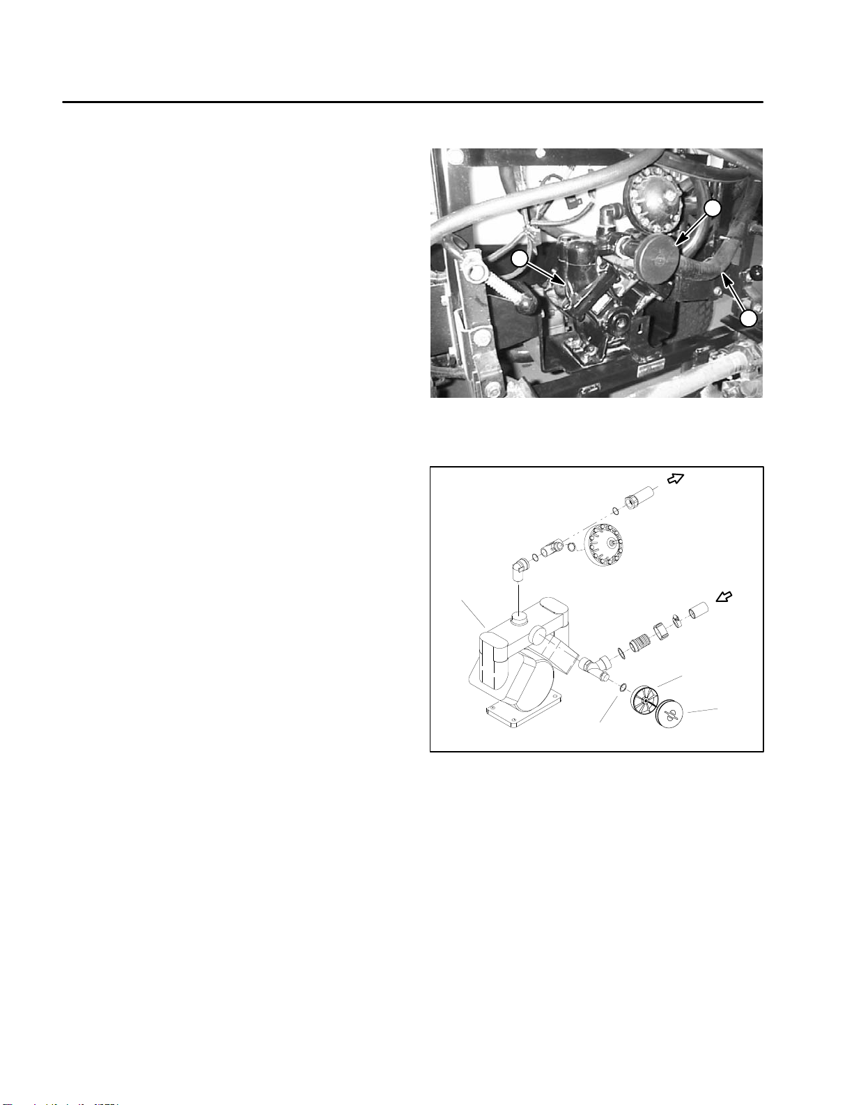
Suction Dampener
The suction dampener is mounted to the suction line at
the spray pump (Fig. 2) and is used to dampen suction
pulses and smooth suction flow. During pump operation,
the suction dampener diaphragm will move.
IMPORTANT: Make sure to neutralize and remove
chemicals from pump and hoses before loosening
and removing spray system components.
A damaged suction dampener diaphragm will allow a
suction leak and will cause improper pump operation. If
the diaphragm is damaged, remove diaphragm from
dampener housing and replace it (Fig. 3).
1
1. Spray pump
2. Suction dampener
2
3
Figure 2
3. Suction hose
1
1. Spray pump
2. O–ring
3
4
2
Figure 3
3. Dampener housing
4. Diaphragm
Spray System
Page 3 – 8
Workman 200 Spray System
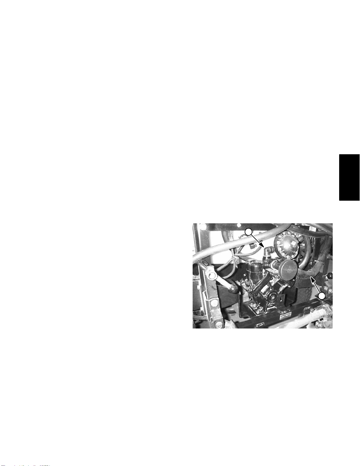
Page 27
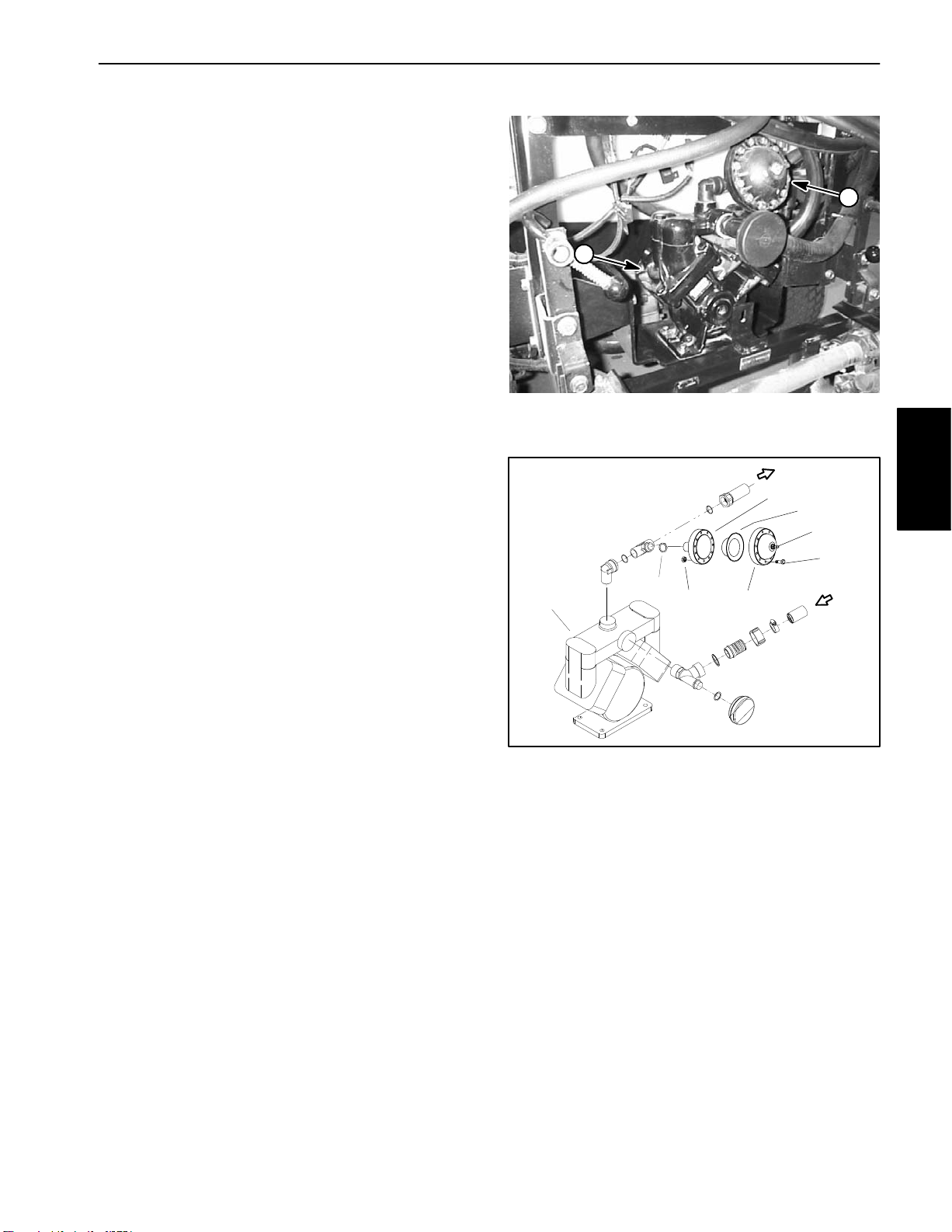
Pressure Dampener
The pressure dampener is mounted to the pressure line
at the spray pump (Fig. 4) and is used to smooth system
pressure pulsation. Adjust air pressure on the pressure
dampener from 12 to 15 PSI (.82 to 1.03 bar).
IMPORTANT: Any fluid in the pressure dampener
will include spray system chemicals so take necessary precautions when working with the dampener.
Use appropriate protective equipment: protective
clothing, chemical resistant gloves, and eye protection.
If fluid is present when pressure in the dampener is
checked, the diaphragm in the pressure dampener is
damaged and should be replaced.
2
1
Dampener Service (Fig. 5)
IMPORTANT: Make sure to neutralize and remove
chemicals from pump and hoses before loosening
and removing spray system components.
1. Loosen and remove cap screws and nuts that secure
diaphragm between housings.
2. Remove diaphragm from dampener.
3. Replace diaphragm and reassemble dampener.
Figure 4
1. Spray pump 2. Pressure dampener
4
5
8
7
1
2
3
6
Figure 5
1. Spray pump
2. O–ring
3. Hex nut (12 used)
4. Rear housing
5. Diaphragm
6. Front housing
7. Cap screw (12 used)
8. Air valve
Spray
System
Workman 200 Spray System
Page 3 – 9
Spray System
Page 28
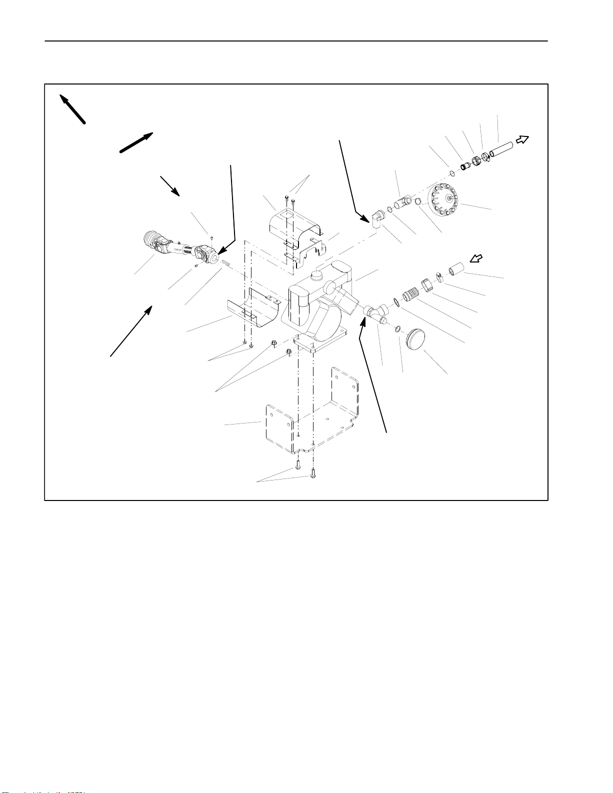
Spray Pump
p
FRONT
RIGHT
Loctite #242
Loctite #242
17
16
15
13
16
Anti–seize
Lubricant
18
19
13
Apply thread sealant
12
14
22
11
10
9
8
7
4
6
5
3
2
1
28
27
26
25
24
5
23
1. Spray pump assembly
2. Elbow (pressure)
3. Gasket
4. Pressure tee fitting
5. O–ring
6. Pressure dampener
7. O–ring
8. Hosebarb
9. Nut
10. Hose clam
20
21
Figure 6
11. Pressure hose
12. Flange head screw (4 used)
13. Pump drive shroud
14. Shroud bracket
15. Square key
16. Set screw
17. PTO driveshaft
18. Flange nut (4 used)
19. Flange nut (4 used)
Apply thread sealant
20. Pump mount bracket
21. Flange head screw (4 used)
22. Suction tee fitting
23. Suction dampener
24. Gasket
25. Hosebarb
26. Nut
27. Hose clamp
28. Suction hose
Spray System
Page 3 – 10
Workman 200 Spray System
Page 29
Removal (Fig. 6)
IMPORTANT: Make sure to neutralize and remove
chemicals from pump and hoses before loosening
and removing spray system components.
1. Park machine on a level surface, stop engine, engage parking brake, and remove key from the ignition
switch.
2. Loosen hose clamp that secures suction hose (item
28) to hosebarb (item 25). Pull suction hose from hose
-
barb.
3. Loosen hose clamp that secures pressure hose
(item 11) to hosebarb (item 8). Pull pressure hose from
hosebarb.
4. Remove PTO driveshaft (item 17) from output shaft
of transaxle PTO assembly.
5. Remove four (4) flange head screws and flange nuts
that secure pump assembly to pump mount bracket.
3. Install elbow (pressure), pressure tee fitting, and
pressure dampener to pump outlet. Orientate elbow to
-
ward right side of machine (Fig. 7).
4. Remove set screws (item 16) from PTO driveshaft.
Clean threads of set screws and set screw threads in dri
-
veshaft.
5. Apply anti–seize lubricant to pump shaft. Position
square key in pump shaft and slide PTO driveshaft fully
onto pump shaft.
6. Apply Loctite #242 (or equivalent) to threads of set
screws. Install set screws into PTO drive shaft to secure
PTO shaft to pump shaft.
7. Position pump drive shrouds (item 13) to shroud
bracket (item 14). Install four (4) flange head screws and
flange nuts to secure shrouds to bracket.
8. Position pump on pump mount bracket. Install flange
head screws and flange nuts to pump and mount brack
-
et. Secure pump to mount bracket.
6. Remove pump assembly (with PTO driveshaft and
drive shrouds attached) from machine.
7. Remove four (4) flange head screws and flange nuts
that secure pump drive shrouds (item 13) to shroud
bracket (item 14). Remove pump drive shrouds.
8. Loosen two (2) set screws (item 16) that secure PTO
drive shaft to pump shaft. Separate PTO drive shaft from
pump. Locate and remove key from pump shaft.
9. As needed, remove pressure and suction components from pump using Figure 6 as a guide. Discard any
removed o–rings and gaskets.
Installation (Fig. 6)
NOTE: Coat all o–rings with vegetable oil before instal-
lation to reduce the chance of damage during assembly.
1. Apply thread sealant to threads of pressure tee fitting, elbow (pressure), and suction tee fitting. Position
new o–rings and gaskets on suction and pressure fit
-
tings that were removed during disassembly.
2. Install suction tee fitting and suction dampener to
pump inlet. Orientate tee toward right side of machine
(Fig. 7).
9. Attach PTO driveshaft to output shaft of transaxle
PTO assembly.
10.Install pressure and suction hoses to correct barb fittings. Secure hoses with hose clamps.
1
2
Figure 7
1. Elbow (pressure) 2. Suction hose
Spray
System
Workman 200 Spray System
Page 3 – 11
Spray System
Page 30
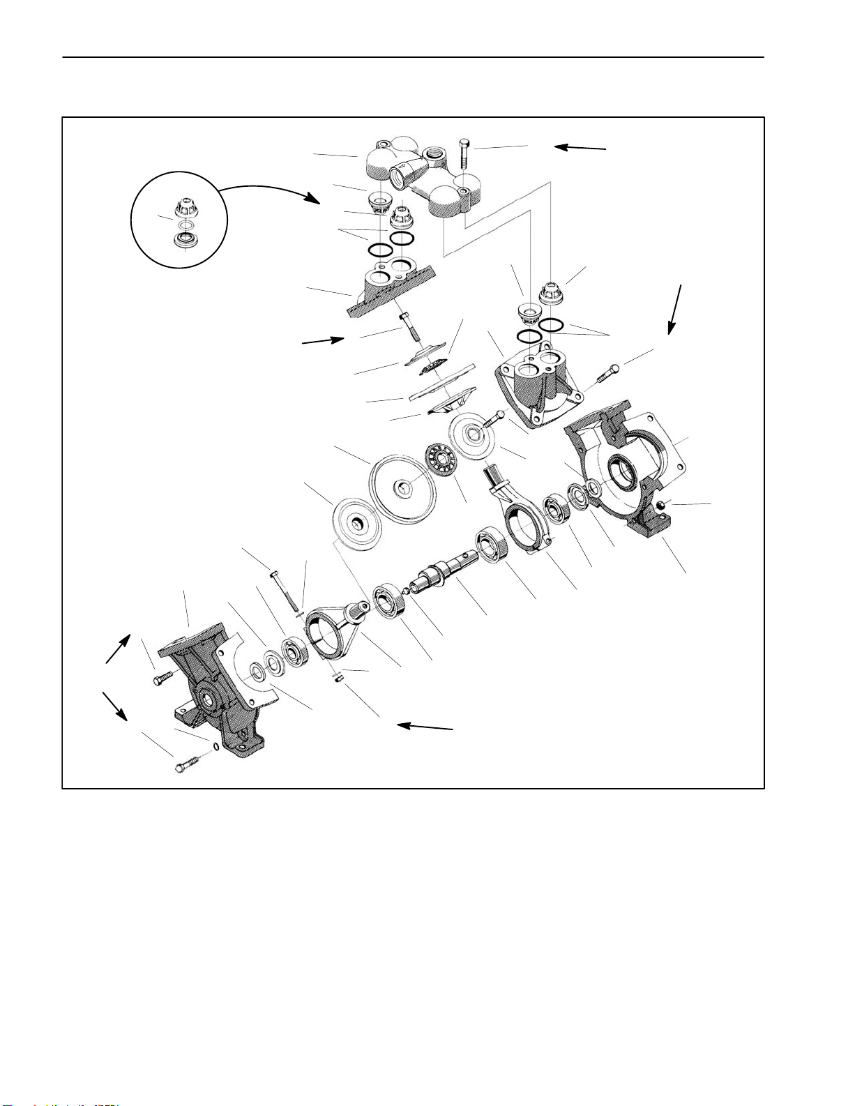
Spray Pump Service
15
28
14
13
11
60 ft–lb
(81 N–m)
12
1
2
25
3
4
9
4
5
6
7
8
7
8
9
10
23
22
26
2
5
18
6
21
20
25
12
60 ft–lb
(81 N–m)
3
13
55 ft–lb
(75 N–m)
16
24
14
32 ft–lb
(43 N–m)
27
17
1. Valve chamber
2. Valve (inlet position)
3. O–ring
4. Diaphragm cover
5. Hex bolt
6. Washer
7. Diaphragm
8. Diaphragm back disc
9. Nylon washer
10. Lock washer
Spray System
20
21
25 ft–lb
(34 N–m)
18
10
19
Figure 8
11. Hex bolt
12. Ball bearing (crankshaft)
13. Dust plate
14. Pump casing
15. Hex bolt (30 mm long) (3 used)
16. Hex bolt (4 used per cover)
17. Hex bolt (55 mm long) (2 used)
18. Felt seal
19. Hex nut
Page 3 – 12
20. Connecting rod
21. Ball bearing (connecting rod)
22. Grease fitting
23. Crankshaft
24. Hex nut (5 used)
25. Valve (outlet position)
26. Hex bolt (2 used)
27. Washer (2 used)
28. Poly o–ring
Workman 200 Spray System
Page 31

Disassembly (Fig. 8)
IMPORTANT: Make sure to remove and neutralize
chemicals from pump before disassembly. Wear
protective clothing, chemical resistant gloves, and
eye protection during pump repair.
NOTE: Many pump components can be easily re-
versed. During disassembly, make note of component
position (e.g. crankshaft, valve chamber) to assure cor
-
rect assembly.
1. Remove two (2) hex bolts that retain valve chamber
to pump. Separate valve chamber from pump.
2. Remove inlet and outlet valves and o–rings from
each diaphragm cover. Note orientation of valves. Dis
card valves and o–rings. Clean valve and o–ring seats
in the valve chambers and diaphragm covers.
3. Remove hex bolts that secure diaphragm covers to
pump. Remove diaphragm covers.
D. Position dust plate and felt seal on both ends of
crankshaft.
IMPORTANT: If connecting rod position is incorrect, pump will not operate properly.
E. Slide crankshaft assembly into pump casing. The
rear connecting rod should be positioned to the left
side and the connecting rod closest to you to the right
side (Fig. 9).
2. Place second pump casing onto assembly. Pump
casing surfaces should mate together.
3. Install three (3) shorter (30 mm) bolts and two (2) longer (55 mm) bolts with washers into pump casing assembly (Fig. 10). Thread hex nuts onto bolts but do not
fully tighten. Check that crankshaft turns freely.
4. Remove hex bolt, washer, nylon washer, diaphragm,
and diaphragm back disc from each connecting rod.
Discard diaphragms.
5. Remove five (5) hex bolts and nuts that secure pump
casing halves together. Note location of two (2) longer
hex bolts with washers. Carefully separate pump casing
halves.
6. Clean grease from bottom of housing and check condition of bearings on crankshaft. If bearings require replacement, remove and disassemble crankshaft:
A. Remove crankshaft assembly from pump casing.
B. Slide felt seal and dust plate from both ends of
crankshaft.
C. Loosen hex bolt and hex nut that secure connecting rods to crankshaft. Slide connecting rods from
crankshaft. Press ball bearings from crankshaft.
Assembly (Fig. 8)
1. If disassembled, reassemble crankshaft.
A. Hand pack new bearings with #2 general purpose
lithium base grease.
2
Figure 9
1. Closest connecting rod (to right side)
2. Rear connecting rod (to left side)
1
1
2
2
Spray
System
1
1
B. Pressing on bearing inner race, install two connecting rod and two crankshaft ball bearings onto
crankshaft.
C. Slide connecting rods onto connecting rod bearings. Offsets of the connecting rods should face each
other. Install hex bolt, flat washers, and hex nut to
each connecting rod. Torque hex nuts to 25 ft–lb (34
N–m) to secure connecting rods to crankshaft.
Workman 200 Spray System
1. Hex bolt (30 mm long) 2. Hex bolt (55 mm long)
Page 3 – 13
Figure 10
Spray System
Page 32

4. Place diaphragm back disc and new diaphragm onto
each connecting rod. The connecting rods should ex
tend above the diaphragms when correctly installed
(Fig. 11). Position nylon washer and washer on each
connecting rod and then thread hex bolt into connecting
rod. Torque bolt to 60 ft–lb (81 N–m).
5. Make sure that pump casings align and then secure
pump casing assembly by torquing five (5) bolts to 32 ft–
lb (43 N–m).
6. Secure diaphragm covers to pump using hex bolts (4
per cover). Torque bolts to 55 ft–lb (75 N–m).
7. Place new o–rings and valves into diaphragm cover
openings (Fig. 12). Inlet valves should be installed with
the spring down into the cover and should be on the
same side of the pump as the crankshaft grease fitting.
Outlet valves should be installed with the spring up and
away from cover and should be on the same side of the
pump as the crankshaft extension.
8. Place valve chamber over valves noting orientation
of chamber inlet and outlet. Secure valve chamber with
two (2) hex bolts. Torque bolts 60 ft–lb (81 N–m).
2
1
Figure 11
1. Diaphragm 2. Connecting rod
1
3
2
2
Figure 12
1. Inlet (suction) 3. Outlet valve
2. Inlet valve
Spray System
Page 3 – 14
Workman 200 Spray System
Page 33

This page is intentionally blank.
Spray
System
Workman 200 Spray System
Page 3 – 15
Spray System
Page 34

Agitation Control Valve
FRONT
8
A
RIGHT
4
1
4
2
7
3
6
5
A
8
1. Agitation control valve
2. Fork
3. Hosebarb/hose (to agitation nozzles)
Spray System
Figure 13
4. O–ring
5. O–ring
6. Hosebarb/hose (from spray control)
Page 3 – 16
NOTE: ARROWS SHOW FLUID
FLOW DIRECTION
7. Connector
8. Pump suction hose
Workman 200 Spray System
Page 35

Removal (Fig. 13)
IMPORTANT: Make sure to remove and neutralize
chemicals from spray components before disas
sembly. Wear protective clothing, chemical resistant gloves, and eye protection during repair.
1. Park machine on a level surface, stop engine, engage parking brake, and remove key from the ignition
switch.
4
-
3
1
2. Label disconnected hoses for proper installation after repairs are completed.
3. Remove agitation control valve using Figures 13 and
14 as guides.
4. Disassemble agitation valve as required (Fig 15).
Installation (Fig. 13)
NOTE: Coat all o–rings with vegetable oil before instal-
lation to reduce the chance of damage during assembly.
1. Assemble agitation control valve (Fig 15). Align arrow on valve handle with large hole in valve ball during
assembly (Fig. 16).
2. Install agitation valve using Figures 13 and 14 as
guides.
3. Check spray system for leaks.
2
Figure 14
1. Agitation control valve 3. Suction hose (from tank)
2. Control bypass hose 4. Suction hose (to pump)
10
12
13
15
14
3
2
4
7
5
16
9
11
7
4
8
3
6
5
2
1
Figure 15
1. Valve housing
2. Ball seat
3. O–ring
4. O–ring
5. Washer (8 used)
6. Cap screw (4 used)
7. End cover
8. Screw (4 used)
9. Screw
10. Button
11. Valve handle
12. Disc
13. O–ring
14. Spindle
15. Valve ball
16. Lock nut (4 used)
Spray
System
Workman 200 Spray System
1. Valve handle arrow 2. Valve ball large hole
Page 3 – 17
2
1
Figure 16
Spray System
Page 36

Agitation Nozzles (Tank mounted)
FRONT
11
19
RIGHT
6
C
17
18
16
20
4
8
7
11
22
10
7
8
11
4
9
16
B
15
C
2
12
11
10
9
12
7
13
14
A
4
8
6
4
6
B
23
A
5
1
2
3
21
1. Agitation supply
2. Tee fitting
3. Hosebarb/hose
4. O–ring
5. Connector
6. Bulkhead nut
7. Gasket
8. Bulkhead fitting
Figure 17
9. Hosebarb
10. Agitation nozzle
11. Nut
12. Fork (12 used)
13. Hosebarb/hose
14. Hosebarb/hose
15. Hosebarb/hose
16. Agitation nozzle
NOTE: ARROWS SHOW FLUID
FLOW DIRECTION
17. Hosebarb/hose
18. Tee fitting
19. Nipple
20. Adapter
21. O–ring
22. Elbow
23. Hosebarb/hose
Spray System
Page 3 – 18
Workman 200 Spray System
Page 37

Disassembly (Fig. 17)
Assembly (Fig. 17)
IMPORTANT: Make sure to remove and neutralize
chemicals from tank and other components before
disassembly. Wear protective clothing, chemical re
sistant gloves, and eye protection during repair.
1. Park machine on a level surface, stop engine, engage parking brake, and remove key from the ignition
switch.
2. Drain spray tank (see Operator’s Manual).
3. Label hoses for proper installation after repairs are
completed.
4. Remove agitation nozzles as required using Figure
17 as a guide. Discard all removed o–rings and gaskets.
NOTE: Coat all o–rings with vegetable oil before installation to reduce the chance of damage during assembly.
-
1. Install agitation nozzles using Figure 17 as a guide.
Replace all removed o–rings and gaskets.
2. Check spray system for leaks.
Spray
System
Workman 200 Spray System
Page 3 – 19
Spray System
Page 38

Pressure Relief Valve (Tank Mounted)
FRONT
RIGHT
1. Hosebarb/hose
2. Ringnut
3. Pressure relief valve
Figure 18
4. Gasket
5. Hosebarb/hose
6. O–ring
5
6
A
8
7
3
4
A
NOTE: ARROWS SHOW FLUID
1
2
FLOW DIRECTION
7. Fork
8. Hosebarb/hose (from spray pump)
Spray System
Page 3 – 20
Workman 200 Spray System
Page 39

Removal (Fig. 18)
IMPORTANT: Make sure to remove and neutralize
chemicals from tank and other components before
disassembly. Wear protective clothing, chemical re
sistant gloves, and eye protection during repair.
-
1. Park machine on a level surface, stop engine, engage parking brake, and remove key from the ignition
switch.
2. Drain spray tank (see Operator’s Manual).
3. Label disconnected hoses for proper installation after repairs are completed.
4. Remove pressure relief valve from spray tank using
Figure 18 and 19 as guides. Discard all removed o–rings
and gaskets.
5. Disassemble pressure relief valve using Figure 20
as a guide.
Assembly (Fig. 18)
NOTE: Coat all o–rings with vegetable oil before instal-
lation to reduce the chance of damage during assembly.
1. Assemble and install pressure relief valve using Figure 18, 19 and 20 as guides. Replace all removed o–
rings and gaskets.
2. Check spray system for leaks.
2
3
1
Figure 19
1. Hose to pressure relief 3. Control supply hose
2. Hose from spray pump
4
3
2
1
5
Spray
System
Figure 20
1. Nut 4. Cone
2. Seat 5. Relief valve housing
3. Spring
Workman 200 Spray System
Page 3 – 21
Spray System
Page 40

Spray Control (Serial Numbers Below 290999999)
FRONT
71 in--lb
(8 N--m)
1
RIGHT
2
NOTE: ARROWS SHOW FLUID
FLOW DIRECTION
21
22
23
10
41
5
26
7
7
71 in--lb
(8 N--m)
3
1
29
28
10
30
13
7
29
19
25
40
20
39
7
24
29
30
17
18
16
15
14
11
8
7
7
12
6
5
4
3
10
9
31
29
29
7
32
33
12
Figure 21
1. Nut
2. Threaded rod
3. Washer
4. Bushing
5. O--ring
6. Cap
7. O--ring
8. Tee piece
9. Hose: control supply (1”)
10. Hose clamp
11. Fork
12. Screw
13. Control valve bracket
14. Rate control valve housing
15. Rate control motor
16. Screw (4 used)
17. Screw
18. O--ring
19. Lock washer
20. Handgrip
21. Flowmeter assembly
22. Flowmeter housing
23. Hose: control bypass (1”)
24. Hosebarb
25. O--ring
26. End cap
27. Hose: boom bypass (1”)
28. Hosebarb
IMPORTANT: Rate control and boom valve motors
may have a fuse for circuit protection. Make sure
that correct fuse is installed in the in--line fuse holder located in the motor harness.
32
35
34
32
36
38
35
12
32
32
32
34
37
29. Fork
30. Joiner
31. LH boom valve motor/manifold
32. O--ring
33. End cap
34. Joiner
35. Boom valve bracket
36. O--ring (3 used)
37. Hosebarb: boom supply (3 used)
38. Nut (3 used)
39. Coupler (pressure gauge)
40. Center boom valve motor/manifold
41. RH boom valve motor/manifold
27
Rev. B
Workman 200 Spray SystemPage 3 -- 22Spray System
Page 41

IMPORTANT: Make sure to remove and neutralize
chemicals from spray components before disas
sembly. Wear protective clothing, chemical resistant gloves, and eye protection during repair.
-
1
3
4
5
Removal (Fig. 21)
1. Park machine on a level surface, stop engine, engage parking brake, and remove key from the ignition
switch.
2. Label hoses for proper installation after repairs are
completed. Loosen hose clamps and disconnect hoses
from spray control.
3. Unplug electrical connectors from rate control motor,
flowmeter, and three (3) boom valve motors from ma
chine electrical harness.
4. Remove pressure gauge tube from coupler on back
of flowmeter housing (Fig. 23).
5. Remove three (3) flange head screws that secure
spray control assembly to valve mounting bar. Remove
spray control assembly from machine.
6. Remove spray control components as required using Figure 21 as a guide. Discard all removed o–rings
and gaskets.
Assembly (Fig. 21)
NOTE: Coat all o–rings with vegetable oil before instal-
lation to reduce the chance of damage during assembly.
2
6
-
1. Rate control motor 4. Center boom valve motor
2. Flowmeter 5. RH boom valve motor
3. LH boom valve motor 6. Valve mounting bar
2
3
Figure 22
1
Spray
System
1. Install spray control components using Figure 21 as
a guide. Replace all removed o–rings and gaskets.
2. Before installing rod (Item 2) into assembly, thread
nut (item 1) fully onto rod end that has fewer threads.
Make sure that o–ring (Item 3) is not damaged during
installation over rod. To secure assembly, torque nut 71
in–lb (8 N–m).
3. Position spray control assembly to valve mounting
bar and secure with three (3) flange head screws.
4. Install hoses to correct locations on spray control assembly. Secure hoses with hose clamps.
5. Install pressure gauge tube to coupler on back of
flowmeter housing (Fig. 23).
6. Plug electrical connectors from rate control motor,
flowmeter, and three (3) boom valve motors to machine
electrical harness.
7. Operate spray system and check for leaks.
Figure 23
1. Flowmeter 3. Coupler
2. Pressure gauge tube
Workman 200 Spray System
Page 3 – 23
Spray System
Page 42

Spray Control (Serial Numbers Above 310000000)
1
FRONT
RIGHT
2
10
9
11
5
8
6
7
5
6
13
4
17
19
18
8
16
3
12
20
12
13
14
15
NOTE: ARROWS SHOW FLUID
FLOW DIRECTION
1. Flange nut (2 used)
2. Flange nut (8 used)
3. Flange head screw (2 used)
4. Valve mount
5. Flange head screw (8 used)
6. Gasket (2 used)
7. Flowmeter
Figure 23.1
8. Clamp (2 used)
9. Boom valve manifold
10. Pressure gauge tube
11. Coupler (pressure gauge)
12. Hose clamp (3 used)
13. Hose clamp (3 used)
14. Hose: boom bypass
15. Hose: RH boom supply
16. Hose: center boom supply
17. Hose: LH boom supply
18. Regulating valve assembly
19. Hose: control bypass
20. Hose: control supply
Page 3 -- 23.1 Workman 200 Spray SystemSpray System
Rev. B
Page 43

Disassembly (Fig. 23.1)
IMPORTANT: Make sure to remove and neutralize
chemicals from tank and spray components before
disassembly. Wear protective clothing, chemical resistant gloves, and eye protection during repair.
1. Park machine on a level surface, stop engine, engage parking brake, and remove key from the ignition
switch.
2. Label all spray control assembly hoses for proper
installation after repairs are completed. Loosen hose
clamps and disconnect hoses from spray control.
3. Label all wire harness leads for assembly purposes.
Disconnect wire harness connectors from regulating
valve, flowmeter and three (3) boom valve motors.
4. Remove pressure gauge tube (item 10) from coupler
on pressure gauge port on right side of boom valve manifold assembly.
3. Using labels placed during disassembly, install
hoses to correct locations on spray control assembly.
Secure hoses with hose clamps.
4. Install pressure gauge tube (item 10) to coupler on
pressure gauge port on right side of boom valve manifold assembly.
5. Using labels placed during disassembly, secure wire
harness connectors to regulating valve, flowmeter and
three (3) boom valve motors.
6. Operate spray system and check for leaks. Repair all
leaks before returning the sprayer to service.
3
2
1
5. Support spray control assembly to prevent it from falling.
6. Remove eight (8) flange head screws, flat washers
and flange nuts that secure spray control assembly to
valve mount. Remove spray control assembly from machine.
IMPORTANT: Before removing flowmeter from
spray control assembly, note direction of arrow on
top of flowmeter (Fig. 23.3). The arrow should point
toward boom valve manifold assembly.
7. Separate spray control assembly as required using
Figure 23.1 as a guide. Discard all removed gaskets.
Assembly (Fig. 23.1)
NOTE: Coat all gaskets and o--rings with vegetable oil
before installation to reduce the chance of damage during assembly.
1. Assemble spray control using Figure 23.1 as a
guide. Replace all removed gaskets. Make sure that arrow on flowmeter body points toward boom valve manifold assembly (Fig. 23.3).
2. Position spray control assembly to valve mounting
bar and secure with eight (8) flange head screws, flat
washers and flange nuts.
Figure 23.2
1. Boom valve manifold
2. Flowmeter
NOTE ARROW
DIRECTION
FROM
REGULATING
VALV E
Figure 23.3
3. Regulating valve
TO BOOM
VALV E
MANIFOLD
Spray
System
Page 3 -- 23.2Workman 200 Spray System Spray System
Rev. B
Page 44

Flowmeter (Serial Numbers Below 290999999)
1
71 in--lb
(8 N--m)
FRONT
RIGHT
10
24
22
20
23
17
28
19
25
71 in--lb
(8 N--m)
57
3
1
21
18
14
11
8
7
6
2
7
12
13
5
4
3
9
10
26
15
7
16
27
1. Nut
2. Threaded rod
3. Washer
4. Bushing
5. O--ring
6. Cover
7. O--ring
8. Tee piece
9. Hose: control supply (1”)
10. Hose clamp
Figure 24
11. Fork
12. Screw
13. Control valve bracket
14. Rate control motor/housing
15. O--ring
16. Hosebarb
17. Hose: control bypass (1”)
18. Coupler (pressure gauge)
19. Flowmeter housing
NOTE: ARROWS SHOW FLUID
FLOW DIRECTION
20. O--ring
21. Flowmeter rotor shaft
22. Flowmeter rotor
23. Flow sensor
24. Nut
25. End cap
26. LH boom control motor
27. Center boom control motor
28. RH boom control motor
Rev. B
Workman 200 Spray SystemPage 3 -- 24Spray System
Page 45

Removal and Inspection (Fig. 24)
IMPORTANT: Make sure to remove and neutralize
chemicals from spray components before disas
sembly. Wear protective clothing, chemical resistant gloves, and eye protection during repair.
1. Park machine on a level surface, stop engine, engage parking brake, and remove key from the ignition
switch.
2. Loosen and remove nut that secures flow sensor to
flowmeter housing. Carefully remove flow sensor from
housing.
-
1
2
3. Inspect for worn rotor shaft and/or bushings. Make
sure that rotor magnets are not missing or damaged.
4. Clean rotor, rotor shaft, and flowmeter sensor if required (see Operator’s Manual).
5. With the flow sensor harness connected to the machine and the ignition key in the ON position, slowly spin
the flowmeter rotor. The flowmeter LED should illumi
nate as a rotor magnet passes the flow sensor and
should go out as the next magnet passes the sensor.
NOTE: When using a magnet to check the flowmeter,
make sure to alternately use both north and south poles
of the magnet.
6. If the flowmeter LED does not flash, remove rotor
and rotor shaft from sensor. With the flowmeter harness
connected to the machine and the ignition key in the ON
position, slowly pass alternate poles of a magnet past
the flow sensor. If the flowmeter LED flashes as the
magnet poles pass the sensor, replace the rotor and ro
tor shaft. If the flowmeter LED does not flash as the magnet poles pass the sensor, replace the flow sensor.
7. If necessary, remove flowmeter housing using Figures 24 and 26 as guides (also see Spray Control) in this
section). Discard all removed o–rings and gaskets.
Figure 25
1. Rotor shaft 2. Rotor
1
3
2
4
5
Figure 26
1. Rate control motor 4. Center boom valve motor
2. Flowmeter 5. RH boom valve motor
3. LH boom valve motor
Spray
System
Assembly (Fig. 24)
NOTE: Coat all o–rings with vegetable oil before instal-
lation to reduce the chance of damage during assembly.
NOTE: When installing flow sensor into housing, make
sure to align locating pin on sensor flange with hole in
housing.
1. Reassemble flowmeter using Figures 24 and 26 as
guides. Replace all removed o–rings and gaskets.
2. Operate spray system and check for leaks.
Workman 200 Spray System
Page 3 – 25
Spray System
Page 46

Flowmeter (Serial Numbers Above 310000000)
7
9
NOTCH
8
5
NOTE ARROW
DIRECTION
1
NOTCH
5
4
1. Flowmeter body
2. Rotor/magnet assembly
3. Upstream hub with bearing
2
3
6
THREAD
SEALANT
Figure 26.1
4. Downstream hub
5. Retaining ring (2 used)
6. Turbine stud with bearing
7. Sensor assembly
8. Cable clamp
9. Screw
Page 3 -- 25.1 Workman 200 Spray SystemSpray System
Rev. B
Page 47

Removal and Inspection (Fig. 26.1)
IMPORTANT: Make sure to remove and neutralize
chemicals from spray components before disassembly. Wear protective clothing, chemical resistant gloves, and eye protection during repair.
1. Remove spray control assembly from machine and
separate flowmeter from spray control (see Spray Control Assembly (Serial Numbers Above 310000000) Removal in this section).
2. Disassemble flowmeter as required using Figures
26.1 and 26.3 as guides.
3. Clean rotor (item 2), both hubs (items 3 and 4) and
flowmeter body to remove any metal filings, spray
chemicals or other materials.
3
Figure 26.2
1. Boom valve manifold
2. Flowmeter
2
3. Regulating valve
1
Assembly (Fig. 26.1)
1. Assemble flowmeter using Figures 26.1 and 26.3 as
guides. Check the following items during flowmeter assembly.
A. If turbine stud (item 6) was removed from upstream hub, apply thread sealant to threads of stud
before installation.
B. Check that rotor spins freely with very little drag. If
necessary, loosen the turbine stud 1/16 of a turn and
check rotor drag. Continue the process of loosening
stud until rotor spins freely.
C. When installing hubs (items 3 and 4) into housing, make sure to align locating notch on each hub
with boss in housing bore.
D. If sensor (item 7) was removed from flowmeter
body, thread sensor into housing so that it lightly bottoms in the housing. Secure sensor in position by
tightening jam nut.
E. Make sure that retaining rings are fully seated in
grooves of flowmeter housing.
6
5
2
1. Flowmeter body
2. Retaining ring
3. Upstream hub
Figure 26.3
4. Rotor
5. Downstream hub
6. Sensor
1
Spray
System
3
2
4
2. Attach flowmeter assembly to spray control and then
install spray control assembly to machine (see Spray
Control Assembly (Serial Numbers Above 310000000)
Installation in this section).
Page 3 -- 25.2Workman 200 Spray System Spray System
Rev. B
Page 48

Rate Control Motor (Serial Numbers Below 290999999)
1
12
13
3
1
5
8
11
2
4
6
7
9
14
Figure 27
1. Phillips head screw (5 used)
2. Lock washer
3. Hand grip
4. O--ring
5. Phillips head screw (4 used)
6. Rate control motor assembly
7. Gasket
8. Phillips head screw (4 used)
9. Rate valve spindle section
10. Rate control valve housing
The rate control motor allows the operator to vary the
spray application rate. The pressure increase/decrease
switch on the spray console energizes the rate control
motor which adjusts the valve opening and allows some
flow to bypass the spray booms.
NOTE: The rate control motor affects flow to all spray
booms. Therefore, a problem with the rate control motor
will affect all booms and nozzles.
Disassembly and Inspection (Fig. 27)
IMPORTANT: Make sure to remove and neutralize
chemicals from spray components before disassembly. Wear protective clothing, chemical resistant gloves, and eye protection during repair.
10
11. O - -ring
12. Cone
13. Control valve
14. Seal
1. To remove the rate control motor:
A. Adjust the rate control to maximum to allow the
rate control motor spring to relax. This can be done
with either the increase/decrease switch on the
spray console or by rotating the hand grip on the motor fully in a clockwise direction.
B. Unplug rate control motor electrical connector
from machine electrical harness.
C. Loosen four (4) phillips head screws (item 5)
evenly to allow removal of the rate control motor.
D. The inside of motor housing should be free of excessive moisture, corrosion, and dirt.
Rev. B
Workman 200 Spray SystemPage 3 -- 26Spray System
Page 49

2. Remove four (4) phillips head screws (item 8) that
secure spindle section to housing. Remove spindle sec
tion.
3. Locate, remove, and discard o–ring (item 11) and
seal (item 14).
4. Remove valve (item 13) and inspect for wear and/or
damage. Replace if needed.
5. If needed, the spindle shaft can be removed by removing lock nut that secures cone (item 12) to shaft.
NOTE: Many individual components for the rate control
motor and spindle section are not available separately.
If individual components are worn or damaged, assem
blies must be replaced. Refer to Parts Catalog.
6. If necessary, remove rate control valve housing from
machine (see Spray Control in this section).
Assembly (Fig. 27)
NOTE: Coat all o–rings with vegetable oil before instal-
lation to reduce the chance of damage during assembly.
-
1
3
2
4
5
-
Figure 28
1. Rate control motor 4. Center boom valve motor
2. Flowmeter 5. RH boom valve motor
3. LH boom valve motor
Spray
System
1. If removed, install rate control valve housing to machine (see Spray Control in this section).
2. If spindle shaft was removed, assemble by reversing
disassembly process. Make sure that spindle shaft sup
port aligns with notches in housing during assembly. Secure spindle assembly with lock nut.
3. Align control valve with tabs in spindle section and
install control valve. Rotate spindle to fully retract control
valve.
4. Install new o–ring (item 11) and seal (item 14) to
spindle section.
5. Position spindle section to rate control valve housing. Secure spindle section with four (4) phillips head
screws (item 8).
6. To ease assembly of the motor, rotate spindle shaft
so the post is about 1/2” (13 mm) from the spindle sec
tion housing. Align slot in motor with post in spindle and
install motor.
7. Secure motor to assembly by evenly tightening four
(4) phillips head screws (item 5).
-
-
Workman 200 Spray System
Page 3 – 27
Spray System
Page 50

Regulating Valve Assembly (Serial Numbers Above 310000000)
10
1
12
11
7
5
4
7
3
10
9
12
6
14
11
9
Figure 28.1
1. Regulating valve motor
2. Hose barb
3. Flange
4. Adaptor
5. Flynut
6. Elbow fitting
7. Mounting bracket (2 used)
8. Fork
9. Washer (4 used)
10. Cap screw (4 used)
The regulating valve allows the operator to vary the
spray application rate. The pressure increase/decrease
switch on the spray console energizes the regulating
valve motor which adjusts the valve opening and allows
some flow to bypass the spray booms.
NOTE: The r egulating valve affects flow to all spray
booms. Therefore, a problem with the regulating valve
will affect all booms and nozzles.
Removal and Inspection (Fig. 28.1)
IMPORTANT: Make sure to remove and neutralize
chemicals from spray components before disassembly. Wear protective clothing, chemical resistant gloves, and eye protection during repair.
1. Remove spray control assembly from machine and
separate regulating valve assembly from spray control
(see Spray Control Assembly (Serial Numbers Above
310000000) Removal in this section).
13
8
2
11. Lock nut (4 used)
12. O--ring (2 used)
13. O--ring
14. O--ring
2. Disassemble regulating valve assembly as needed
using Figure 28.1 as a guide. Discard all removed O-rings and gaskets.
NOTE: There are limited replacement parts available
for regulating valve motor assembly. Check your parts
catalog for parts that are available.
3. To remove valve motor cover from regulating valve
motor (Fig. 28.3):
A. Loosen three (3) screws that secure valve motor
cover to valve motor assembly.
B. Carefully lift and rotate cover from valve motor.
C. Unplug wire connections and remove cover.
D. Make sure that screws that secure valve motor
are tight.
Page 3 -- 27.1 Workman 200 Spray SystemSpray System
Rev. B
Page 51

Assembly (Fig. 28.1)
1. To install valve motor cover to regulating valve motor
(Fig. 28.3):
A. Connect cover wires to motor wires. Make sure
that cover wire c olor is the same as the motor wire
color when connecting wires.
B. Carefully rotate cover onto valve motor taking
care to not damage wires.
C. Tighten screws to secure cover to valve motor.
3
2
1
NOTE: Coat all O--rings with vegetable oil before instal-
lation to reduce the chance of damage during assembly.
2. Assemble regulating valve assembly using Figure
28.1 as a guide.
3. Attach regulating valve assembly to spray control
and then install spray control assembly to machine (see
Spray Control Assembly (Serial Numbers Above
310000000) Installation in this section).
Piston Valve Service (Fig. 28.4)
1. Remove hosebarb from bottom of valve motor to allow access to piston valve.
2. Make sure that valve is closed. If valve is not closed,
spring above piston valve will be under compression
and may damage valve motor or piston valve during disassembly. End of piston valve will extend into bottom of
valve motor housing when valve is closed. If necessary,
reconnect motor to machine wire harness and close
valve before removing piston valve.
3. Use 3mm allen wrench to loosen and remove piston
valve assembly from valve motor. Locate and retrieve
spring from above piston valve.
Figure 28.2
1. Boom valve manifold
2. Flowmeter
3
2
Figure 28.3
1. Valve motor assembly
2. Valve motor cover
3. Wire connector
3. Regulating valve
5
3
1
4. Socket screw (4 used)
5. Phillips screw (2 used)
Spray
System
4
4. Inspect seals on piston valve assembly.O--ring in top
groove of piston valve assembly is available separately.
If lower two (2) seals in piston valve are worn or damaged, replace piston valve assembly. The piston valve
is not designed to be disassembled.
5. Apply silicone grease to seals on piston valve assembly.
6. Position spring into valve motor housing. Use 3mm
allen wrench to secure piston valve assembly to valve
motor.
7. Secure hosebarb to bottom of valve motor.
Page 3 -- 27.2Workman 200 Spray System Spray System
1
Figure 28.4
1. Valve motor assembly
2. Piston valve assembly
3. Valve seal
Rev. B
5
4
3
2
4. Spring
5. Valve motor cover
Page 52

Boom Valve Motor (Serial Numbers Below 290999999)
12
9
10
18
24
27
16
20
26
22
14
29
32
33
70 in--lb
(8 N--m)
28
30
31
1
4
5
7
2
3
6
4
8
11
13
15
17
19
21
23
25
Figure 29
1. Housing cover
2. Cover seal
3. Boom valve motor
4. Phillips head screw (5 used)
5. O--ring
6. Lock washer
7. Hand grip
8. Roller
9. Roller pin
10. Spindle
11. Spr in g
12. Spring seat
13. O--ring
14. Spindle housing
15. Phillips head screw (4 used)
16. O--ring
17. O--ring
18. Flat washer
19. Seat outer o-- ring
20. Seat
21. Seat inner o-- ring
22. Seat base
The Workman 200 Sprayer (serial numbers below
290999999) uses three boom valve motor assemblies
to control the spray booms. Each boom valve motor assembly includes a motor section (Fig. 29, Items 1
through 7), a spindle section (Fig. 29, Items 8 through
27), and a manifold assembly (Fig. 29, Items 28 through
33).
Disassembly and Inspection (Fig. 29)
IMPORTANT: Make sure to remove and neutralize
chemicals from spray components before disassembly. Wear protective clothing, chemical resistant gloves, and eye protection during repair.
1. Remove spray control from machine. Separate
spray control components to allow boom valve motor
disassembly (see Spray Control in this section).
23. Flat washer
24. Spring
25. Flat washer
26. Cone
27. Screw
28. Boom valve manifold housing
29. Fork
30. O--ring
31. Balancing valve
32. Roll pin
33. Balancing valve knob
2. To remove the motor and spindle section assembly
from the manifold assembly:
A. Remove the fork (item 29) that secures the motor
and spindle sections to the manifold assembly.
B. Lift the motor and spindle section assembly from
the manifold.
3. To allow easier separation of the motor and spindle
sections, make sure that boom valve motor is in the
closed position (green indicator is recessed into the
spindle housing). Remove four phillips head screws
(item 15) and separate spindle section from motor section.
Rev. B
Workman 200 Spray SystemPage 3 -- 28Spray System
Page 53

4. Remove rear housing cover from boom valve motor
to inspect motor components.
A. Cam should be tight on shaft. Cam surface
should be free of wear and/or scoring.
1
3
4
5
B. The inside of motor housing should be free of excessive moisture, corrosion, and dirt.
C. The cam bearing surface in the housing cover
should be inspected for excessive wear.
5. Inspect and disassemble spindle section (Fig. 31).
A. Inspect spindle roller surface for wear or scoring.
Check that spindle roller rotates freely on roller pin.
Replace roller and/or pin as required.
B. The spindle can be disassembled by removing
the screw at the bottom of the spindle shaft. Take
note of washer, spring, seat, and o–ring locations as
spindle is removed.
C. Inspect the cone located at the bottom of the
spindle. The cone should be free of nicks or worn
spots. A damaged cone will allow flow to the boom
bypass rather than to the spray boom.
D. The seat o–rings allow the spindle to shut off flow
to the spray boom. If boom nozzles leak when the
boom is shut off, the seat and seat o–rings should be
inspected carefully.
2
Figure 30
1. Rate control motor 4. Center boom valve motor
2. Flowmeter 5. RH boom valve motor
3. LH boom valve motor
1
3
Spray
System
6. If leakage occurs from balancing valve knob at bottom of boom valve manifold (Fig. 32):
A. Carefully remove roll pin that secures balancing
valve to knob.
B. Remove knob from manifold. Remove and discard o–ring.
C. Inspect seating surfaces of manifold and balancing valve. Clean or replace components as needed.
Assembly (Fig. 29)
NOTE: Coat all o–rings with vegetable oil before instal-
lation to reduce the chance of damage during assembly.
1. Replace all removed o–rings.
2. If boom valve manifold was disassembled (Fig. 32):
A. Install o–ring, balancing valve, and knob to manifold.
B. Secure balancing valve to knob by carefully
installing roll pin.
2
Figure 31
1. Spindle roller 3. Seat
2. Cone
1
4
3
2
Figure 32
1. Boom valve manifold 3. Balancing valve knob
2. Balancing valve 4. Roll pin
Workman 200 Spray System
Page 3 – 29
Spray System
Page 54

3. Assemble spindle section by reversing disassembly
process. Align green indicator tab on spindle to slot in
spindle housing. Install screw into bottom of spindle to
secure assembly. Torque screw 70 in–lb (8 N–m).
4. Position spindle section on motor section so that
green indicator on spindle section is opposite the motor
hand grip. Secure spindle section to motor section with
four phillips head screws (item 15).
5. Replace rear housing to boom valve motor.
6. Position the motor and spindle section assembly to
the manifold assembly. The motor hand grip and boom
supply hosebarb on manifold should be on the same
side of the assembly. Install the fork (item 29) to secure
the motor and spindle sections to the manifold.
7. Assemble spray control assembly. Install spray control to machine (see Spray Control in this section).
8. Operate spray system and check for leaks.
Spray System
Page 3 – 30
Workman 200 Spray System
Page 55

This page is intentionally blank.
Spray
System
Workman 200 Spray System
Page 3 – 31
Spray System
Page 56

Boom Valve Manifold Assembly (Serial Numbers Above 310000000)
NOTE: ARROWS SHOW FLUID
FLOW DIRECTION
1
7
12
18
4
18
16
13
1
1
9
12
12
11
14
2
11
3
7
16
10
12
15
13
8
17
5
6
Figure 32.1
1. Boom valve motor (3 used)
2. Hose barb (3 used)
3. Pressure gauge port
4. Flange
5. Flynut
6. Elbow fitting
7. Mounting bracket (2 used)
8. Balancing valve assembly
9. Flange
10. Fork (3 used)
11. Fork(6used)
12. O--ring (4 used)
13. O--ring (4 used)
The sprayer system for serial numbers above
310000000 uses three (3) boom valve motor assemblies to control the spray booms. Each boom valve motor assembly includes a motor section and a balancing
valve assembly.
The boom control switches on the operator spray console are used to energize the boom valve motors and
open the boom valves. The open boom valvesallow system flow to reach the appropriate boom section (right,
center or left).
Disassembly (Fig. 32.1)
IMPORTANT: Make sure to remove and neutralize
chemicals from spray components before disassembly. Wear protective clothing, chemical resistant gloves, and eye protection during repair.
19
14. O--ring (3 used)
15. Balancing valve assembly (2 used)
16. Washer (4 used)
17. Cap screw (4 used)
18. Lock nut (4 used)
19. Cap
1. Remove spray control assembly from machine and
separate boom valve manifold assembly from spray
control (see Spray Control Assembly (Serial Numbers
Above 310000000) Removal in this section).
2. Disassemble boom valve manifold assembly as
needed using Figure 32.1 as a guide. Discard all removed O--rings and gaskets.
NOTE: There are limited replacement parts available
for boom valve motor assembly. Check your parts catalog for parts that are available.
3. To remove cover from boom valve (Fig. 32.3):
A. Loosen three (3) screws that secure valve motor
cover to valve motor assembly.
B. Carefully lift and rotate cover from valve motor.
Page 3 -- 31.1 Workman 200 Spray SystemSpray System
Rev. B
Page 57

C. Unplug wire connections and remove cover.
D. Make sure that screws that secure valve motor
are tight.
Assembly (Fig. 32.1)
1. To install cover to boom valve motor (Fig. 32.3):
A. Connect cover wires to motor wires. Make sure
that cover wire c olor is the same as the motor wire
color when connecting wires.
3
2
1
B. Carefully rotate cover onto valve motor taking
care to not damage wires.
C. Tighten screws to secure cover to valve motor.
NOTE: Coat all O--rings with vegetable oil before installation to reduce the chance of damage during assembly.
2. Assemble boom valve manifold assembly using Figure 32.1 as a guide.
3. Attach boom valve manifold assembly to spray control and then install spray control assembly to machine
(see Spray Control Assembly (Serial Numbers Above
310000000) Installation in this section).
Piston Valve Service (Fig. 32.4)
1. Remove hosebarb from bottom of valve motor to allow access to piston valve.
2. Make sure that valve is closed. If valve is not closed,
spring above piston valve will be under compression
and may damage valve motor or piston valve during disassembly. End of piston valve will extend into bottom of
valve motor housing when valve is closed. If necessary,
reconnect motor to machine wire harness and close
valve before removing piston valve.
3. Use 3mm allen wrench to loosen and remove piston
valve assembly from valve motor. Locate and retrieve
spring from above piston valve.
Figure 32.2
1. Boom valve manifold
2. Flowmeter
3
2
Figure 32.3
1. Valve motor assembly
2. Valve motor cover
3. Wire connector
3. Regulating valve
5
3
1
4. Socket screw (4 used)
5. Phillips screw (2 used)
5
Spray
System
4
4. Inspect seals on piston valve assembly.O--ring in top
groove of piston valve assembly is available separately.
If lower two (2) seals in piston valve are worn or damaged, replace piston valve assembly. The piston valve
is not designed to be disassembled.
5. Apply silicone grease to seals on piston valve assembly.
6. Position spring into valve motor housing. Use 3mm
allen wrench to secure piston valve assembly to valve
motor.
7. Secure hosebarb to bottom of valve motor.
Page 3 -- 31.2Workman 200 Spray System Spray System
1
Figure 32.4
1. Valve motor assembly
2. Piston valve assembly
3. Valve seal
Rev. B
4
3
2
4. Spring
5. Valve motor cover
Page 58

Boom Bypass
FRONT
RIGHT
1
2
3
4
6
5
7
A
5
8
A
1. Boom bypass elbow
2. O–ring
3. Bulkhead fitting
Figure 33
4. Gasket
5. Fork
6. Bulkhead nut
NOTE: ARROW SHOWS FLUID
FLOW DIRECTION
7. Hosebarb/hose
8. Hosebarb/hose
Spray System
Page 3 – 32
Workman 200 Spray System
Page 59

Disassembly (Fig. 33)
IMPORTANT: Make sure to remove and neutralize
chemicals from tank and spray components before
disassembly. Wear protective clothing, chemical re
sistant gloves, and eye protection during repair.
1. Park machine on a level surface, stop engine, engage parking brake, and remove key from the ignition
switch.
2. Drain spray tank (see Operator’s Manual).
3. Disassemble boom bypass using Figures 33 and 34
as guides. Discard all removed o–rings and gaskets.
-
2
1
Assembly (Fig. 33)
NOTE: Coat all o–rings with vegetable oil before instal-
lation to reduce the chance of damage during assembly.
1. Assemble boom bypass using Figures 33 and 34as
guides. Replace all removed o–rings and gaskets.
2. Check spray tank for leaks.
Figure 34
1. Boom bypass elbow 2. Tank suction tube
Spray
System
Workman 200 Spray System
Page 3 – 33
Spray System
Page 60

Tank Suction
1
FRONT
RIGHT
16
2
3
5
7
10
12
17
18
4
6
8
9
11
13
14
15
1. Suction hosebarb
2. O–ring
3. Screen vane
4. Suction screen
5. Fork
6. Filter housing
Spray System
Figure 35
7. Expansion pin
8. Bulkhead gasket
9. Bulkhead nut
10. O–ring
11. Hosebarb
12. Hose clamp
Page 3 – 34
NOTE: ARROW SHOWS FLUID
FLOW DIRECTION
13. Suction hose
14. Suction tube
15. Suction tube foot
16. Spray tank
17. Hose clamp
18. Suction hose (1 1/2”)
Workman 200 Spray System
Page 61

NOTE: If suction tube in tank develops an air leak, spray
performance will diminish when tank level reaches the
leak.
Removal (Fig. 35)
IMPORTANT: Make sure to remove and neutralize
chemicals from tank and spray components before
disassembly. Wear protective clothing, chemical re
sistant gloves, and eye protection during repair.
1. Park machine on a level surface, stop engine, engage parking brake, and remove key from the ignition
switch.
2. Remove suction strainer from spray tank (see Operator’s Manual).
3. Raise tank lid and remove strainer basket to gain access to suction tube inside spray tank (Fig. 36).
4. Remove suction tube assembly from spray tank and
disassemble tube using Figure 35 as a guide. Discard
all removed o–rings and gaskets.
Assembly (Fig. 35)
3
-
2
1
Figure 36
1. Suction strainer 3. Tank lid
2. Tank drain
Spray
1
System
NOTE: Coat all o–rings with vegetable oil before instal-
lation to reduce the chance of damage during assembly.
1. Assemble and install suction tube assembly using
Figure 35 as a guide. Replace all removed o–rings and
gaskets.
2. Check spray tank for leaks.
2
Figure 37
1. Tank suction tube 2. Tank drain
Workman 200 Spray System
Page 3 – 35
Spray System
Page 62

Tank Drain
1
2
3
4
5
6
FRONT
11
RIGHT
7
8
9
10
1. Drain handle
2. Nut
3. O–ring
4. Bulkhead
Figure 38
5. Gasket
6. Ringnut
7. Chain
8. Drain assembly
9. Hose clamp
10. Drain hose
11. Spray tank
Spray System
Page 3 – 36
Workman 200 Spray System
Page 63

Disassembly (Fig. 38)
IMPORTANT: Make sure to remove and neutralize
chemicals from tank and spray components before
disassembly. Wear protective clothing, chemical resistant gloves, and eye protection during repair.
1. Park machine on a level surface, stop engine, engage parking brake, and remove key from the ignition
switch.
2. Drain spray tank (see Operator’s Manual).
3
1
3. Raise tank lid and remove strainer basket to gain access to chain (item 7) that connects drain handle (item
1) to plunger in drain assembly (item 8). Disconnect
chain from drain handle.
4. If necessary, remove drain handle and bulkhead using Figure 38 as a guide.
5. If necessary, remove drain assembly from tank:
A. Loosen hose clamp and slide drain hose from
drain assembly hosebarb.
B. Remove fork from drain assembly to allow hosebarb to be removed from drain assembly.
C. Remove bulkhead nut that secures drain assembly to spray tank.
D. Lift drain assembly from bottom of tank.
6. Disassemble drain assembly using Figure 40 as a
guide.
7. Discard all removed o–rings and gaskets.
1. Tank drain
2. Suction strainer
1
3
6
8
Figure 39
3. Tank lid
2
2
Spray
4
5
7
9
11
System
Assembly (Fig. 38)
NOTE: Coat all o–rings with vegetable oil before instal-
lation to reduce the chance of damage during assembly.
1. Assemble drain tube using Figures 38 and 40 as
guides. Replace all removed o–rings and gaskets.
2. Hosebarb of drain assembly should be orientated toward the rear of the spray tank. Make sure that clearance exists between drain assembly and sprayer frame.
3. Check spray tank for leaks.
Workman 200 Spray System
Page 3 – 37
10
1. Adapter
2. Plunger holder
3. Spring
4. Drain plunger
5. O–ring
6. Drain seat
7. O–ring
12
13
Figure 40
8. Drain bulkhead
9. Fork
10. Gasket
11. Bulkhead nut
12. O–ring
13. Hosebarb
Spray System
Page 64

Turret Bodies
6
7
3
8
3
9
3
5
1. Turret body (w/90o elbow)
o
2. 90
elbow (1 used)
3. Screw
4
4
2
LEFT
BOOM
SUPPLY
1
4
4
CENTER
BOOM
SUPPLY
5
4
RIGHT
BOOM
SUPPLY
1
4
4
5
4
5
Figure 41
4. Turret body (w/double hose barb)
5. Turret body (w/single hose barb)
6. Single hose barb (3 used)
7. Double hose barb (7 used)
8. Turret body clamp
9. Hose barb (for 90
o
elbow)
Removal (Fig. 41)
IMPORTANT: Make sure to remove and neutralize
chemicals from spray components before disassembly. Wear protective clothing, chemical resistant gloves, and eye protection during repair.
1. Park machine on a level surface, stop engine, engage parking brake, and remove key from the ignition
switch.
2. Loosen hose clamp(s) and remove supply hose(s)
from turret body.
3. Remove screw that secures turret body clamp to
spray boom. Separate clamp halves and remove turret
body from machine.
Spray System
Page 3 – 38
Installation (Fig. 41)
NOTE: The type of hose barb on turret body deter-
mines turret location on spray boom. Refer to Figure 41
for turret position on booms.
1. Position turret body clamp halves to spray boom and
turret body. Slide clamp halves together. Position turret
so that spray nozzle and nozzle fan slot are parallel to
ground. Tighten clamp screw to secure turret body.
2. Install supply hose(s) to turret body. Tighten hose
clamp(s).
Workman 200 Spray System
Page 65

Turret Body Service
Disassembly (Fig. 42)
1. Pull e–clip from body and slide plug with o–ring from
body.
2. Disassemble turret body using Figure 42 as a guide.
3. Discard all removed seals, gaskets, o–rings, and diaphragms.
Assembly (Fig. 42)
NOTE: Coat all o–rings with vegetable oil before instal-
lation to reduce the chance of damage during assembly.
1. Replace all removed seals, gaskets, o–rings, and diaphragms.
2. Assemble turret body using Figure 42 as a guide.
A. The turret (item 8) end with slightly larger bore
and detent grooves needs to be orientated toward
detent posts on body (item 4) (Fig. 43).
B. Make sure to align notch on plug (item 10) with
groove in body (item 4) as plug is installed.
C. Install e–clip (item 5) into body to secure assembly.
18
17
16
15
1. Upper clamp
2. O–ring
3. Pivot pin
4. Body
5. E–clip
6. Gasket (3 used)
7. Dust cap (2 used)
8. Turret
9. O–ring
1
2
4
14
Figure 42
3
13
12
10. Plug
11. Nozzle
12. Nozzle cap
13. O–ring
14. Seal
15. Screw
16. End cap
17. Diaphragm
18. Hose barb
5
6
7
8
9
10
6
11
Spray
System
1
3
2
2
Figure 43
1. Body 3. Detent groove
2. Detent post
Workman 200 Spray System
Page 3 – 39
Spray System
Page 66

Boom Frame Breakaway Pivot Assembly (Serial Numbers Below 260000000)
6
7
5
4
16
18
8
9
10
15
6
14
11
3
2
1
10
11
12
13
17
1. Hinge
2. Breakaway pivot
3. Spring
4. Washer
5. Roll pin
6. Hex nut
7. Support bracket
19
20
12
Figure 44
8. Carriage screw
9. Flat washer
10. Cotter pin
11. Clevis pin
12. Clevis pin
13. Main boom frame
14. Breakaway pivot assembly
Rev. A
15. Cap screw
16. Boom support
17. Boom extension pipe
18. Lock nut (4 used per side)
19. Flat washer (4 used per side)
20. Cap screw (4 used per side)
Workman 200 Spray SystemPage 3 -- 40Spray System
Page 67

Disassembly (Fig. 44)
1. Park machine on a level surface, lower booms, stop
engine, engage parking brake, and remove key from the
ignition switch.
2. Support boom to prevent it from falling. Remove cap
screw and hex nut that secure boom support to break
away assembly.
3. Remove hex nut, flat washer, and carriage screw
that secure support bracket to breakaway pivot. Slide
support bracket from breakaway assembly.
CAUTION
Spring in breakaway pivot is under tension. To
prevent possible personal injury, compress
spring before removing roll pin. Wear eye
protection when removing roll pin.
2
3
-
1
4
Figure 45
1. Breakaway pivot 3. Boom support
2. Support bracket 4. Boom extension pipe
4. Compress spring in breakaway assembly slightly.
Drive roll pin from hinge (Fig. 46). Remove flat washer
and spring from assembly.
5. Complete disassembly as required using Figures 44
and 45 as guides.
Assembly (Fig. 44)
1. Assemble breakaway pivot using Figures 44 and 45
as guides.
2. Lubricate grease fitting on breakaway pivot after assembly is complete (see Operator’s Manual).
1
2
Figure 46
1. Roll pin 2. Spring
Spray
System
Workman 200 Spray System
Page 3 – 41
Spray System
Page 68

Boom Hinge (Serial Numbers Above 260000000)
14
13
15
12
16
17
11
10
9
8
18
8
19
9
FRONT
10
20
3
1
2
7
6
4
RIGHT
5
Figure 47
1. Hinge (2 used per boom)
2. Rubber boot (2 used per hinge)
3. Backing plate (4 used per hinge)
4. Flange nut (4 used per hinge)
5. Boom (RH shown)
6. Tee fitting
7. Flange hd screw (4 used per hinge)
8. Lock nut
9. Cap screw
10. Flat washer
11. Pivot bracket
12. Bushing (2 used per pivot bracket)
13. Flange head screw
14. Pivot pin
Disassembly (Fig. 47)
IMPORTANT: Make sure to remove and neutralize
chemicals from spray components before disassembly. Wear protective clothing, chemical resistant gloves, and eye protection during repair.
1. Park machine on a level surface, lower spray booms,
stop engine, engage parking brake and remove key
from the ignition switch.
2. Loosen hose clamp and remove supply hose from
tee fitting (item 6) on spray boom.
3. Support spray boom to prevent it from falling.
15. Flange nut
16. Boom frame
17. Tube (2 used per boom)
18. Spring retainer (2 used per boom)
19. Breakaway spring (2 used per boom)
20. Grease fitting (2 used per hinge)
4. Loosen two (2) cap screws (item 9) and lock nuts
(item 8) to allow breakaway springs (item 18) to fully extend.
5. Complete disassembly as required using Figure 47
as a guide. If pivot bracket (item 11) is to be removed
from machine, disconnect boom actuator (not shown)
from pivot bracket (see Boom Actuator Removal (Machines with Serial Numbers Above 260000000) in this
section).
6. Clean all removed components. If pivot bracket was
removed, inspect bushings and pivot pin for damage or
wear.
Rev. A
Workman 200 Spray SystemPage 3 -- 42Spray System
Page 69

Assembly (Fig. 47)
1. If pivot bracket (item 11) was removed from machine,
lightly lubricate bushings (item 12) with motor oil before
assembly. Connect boom actuator (not shown) to pivot
bracket (see Boom Actuator Installation (Machines with
Serial Numbers Above 260000000) in this section).
2. Make sure that hinges (item 1) are securely fastened
to pivot bracket (item 11) and boom (item 5). The boom
hinge uses four (4) backing plates between the boom
and flange nuts.
3. Position boom hinge to pivot bracket hinge. Make
sure that rubber boots (item 2) are placed at hinge junc
tions and that rib on boots are toward the top of the boom
(Fig. 48).
4. Insert two (2) cap screws (item 9) through flat washers (item 10) and hinges. Place tube (item 17), breakaway spring (item 19), spring retainer (item 18) and lock
nut (item 8) on each cap screw. Make sure that shoulder
on spring retainer fits into breakaway spring.
5. Tighten lock nuts so there is 1.560” (39.6 mm) between the face of the spring retainer and the hinge casting (Fig. 49).
2
UP
1
Figure 48
1. Rubber boot 2. Rib
-
1.560”
(39.6 mm)
Spray
System
6. Connect supply hose to tee fitting on spray boom and
secure with hose clamp.
7. Lubricate grease fittings on boom hinge (see Operator’s Manual).
Figure 49
Workman 200 Spray System
Page 3 – 43
Rev. A
Spray System
Page 70

Boom Actuator (Optional) (Serial Numbers Below 260000000)
5
5
1
2
3
4
1
2
FRONT
RIGHT
3
Figure 50
1. Cotter pin
2. Clevis pin
3. Boom actuator
4. Wire harness
Removal (Fig. 50)
1. Park machine on a level surface, lower booms, stop
engine, engage parking brake, and remove key from the
ignition switch.
2. Label actuator electrical leads to ease reassembly.
Unplug boom actuator connector wires from machine
harness.
3. Support boom to prevent it from falling. Remove cotter pins and clevis pins that attach boom actuator to center and side boom.
4. Pull boom actuator from machine.
5. Adjustable clevis
Installation (Fig. 50)
1. Position boom actuator to clevis attachment points
on center and side booms.
2. Install clevis pins and cotter pins to secure actuator
to boom assembly.
3. Plug actuator connector wires into machine harness.
Make sure that operator switches engage correct actuator.
A. Left side actuator connector has orange and blue
wires.
B. Right side actuator connector has yellow and
green wires.
Rev. A
Workman 200 Spray SystemPage 3 -- 44Spray System
Page 71

Adjustment
1. Loosen end nut that secures adjustable clevis to
boom frame (Fig. 51). Position jam nut as close as pos
sible to adjustable clevis. Tighten end nut to secure clevis.
2. Fully raise side boom with the boom actuator. The
boom actuator should fully extend and ratchet.
3. With the boom actuator at full extension, the breakaway pivot gusset should just touch the center boom
frame slot (Fig. 52).
2
3
1
4
4. If needed, loosen end nut that secures adjustable
clevis and readjust jam nut on clevis to allow correct
boom actuator extension. Tighten end nut to secure clevis adjustment.
Figure 51
1. Boom actuator 3. Jam nut
2. Adjustable clevis 4. End nut
1
2
Figure 52
1. Breakaway pivot gusset 3. Boom actuator
2. Boom frame slot
Spray
System
3
Workman 200 Spray System
Page 3 – 45
Spray System
Page 72

Boom Actuator Service (Serial Numbers Below 260000000)
20
20 in--lb
(2.3 N--m)
1
70 in--lb
(7.9 N--m)
6
4
18
15 16
12
11
9
10
7
5
3
2
14
19
17
70 in--lb
(7.9 N--m)
13
8
3
1. Screw
2. Rear housing
3. Washer
4. Woodruff key
5. Clutch
6. Thin washer
7. Intermediate gear
8. Thick washer
Figure 53
9. Hex nut (2 used)
10. Motor gear
11. Housing gasket
12. Front housing
13. Cover tube gasket
14. Motor seal
15. Motor assembly
16. Ball screw and brake assembly
17. Washer head screw (4 used)
18. Cover tube
19. O--ring
20. O--ring
Rev. A
Workman 200 Spray SystemPage 3 -- 46Spray System
Page 73

Disassembly (Fig. 53)
Assembly (Fig. 53)
1. Remove four (4) washer head screws that secure
cover tube. Remove one (1) screw (item 1) that retains
rear housing. Slide rear housing and housing gasket
from assembly.
2. Slide thin washer, intermediate gear, and thick washer from front housing support pin.
3. In order, remove washer, clutch, woodruff key, and
second washer from ball screw shaft.
4. Pull cover tube from front housing. Remove cover
tube gasket.
5. Loosen and remove two (2) hex nuts that secure motor to front housing. Slide motor, motor gear, and motor
seal from front housing.
6. Remove ball screw and brake assembly from front
housing.
7. Clean actuator components. Replace worn or damaged parts.
8. Discard and replace all removed gaskets and o–
rings.
1. Position ball screw and brake assembly to front
housing. Take care to not disturb brake components.
2. Slide motor, motor gear, and motor seal to front
housing. Secure motor with two (2) hex nuts. Torque
nuts to 70 in–lb (7.9 N–m).
3. Install new o–rings into rear of cover tube. Slide cover tube gasket and cover tube over ball screw.
4. Place washer on ball screw shaft. Position woodruff
key and then slide clutch and second washer onto shaft.
5. Place thick washer, intermediate gear, and thin
washer onto front housing support pin. Make sure that
intermediate gear engages both motor gear and clutch.
6. Position housing gasket to front housing. Slide rear
housing over gears.
7. Secure rear housing:
A. Thread one (1) screw (item 1) through rear housing and into front housing.
B. Install four (4) washer head screws through cover
tube.
Spray
System
C. Torque screw (item 1) to 20 in–lb (2.3 N–m).
Torque four washer head screws to 70 in–lb (7.9
N–m).
Workman 200 Spray System
Page 3 – 47
Spray System
Page 74

Boom Actuator (Serial Numbers Above 260000000)
1
12
11
10
9
8
7
6
2
4
3
1. Boom actuator (2 used)
2. Carriage screw (4 used)
3. Boom frame
4. Washer plate
5
Figure 54
5. Lock nut (4 used)
6. Flange nut (2 used)
7. Flange head screw (2 used)
8. Pivot pin (2 used)
Rev. A
9. Clevis strap (2 used)
10. Boom pivot bracket
11. Clevis pin (2 used)
12. Cotter pin (2 used)
Workman 200 Spray SystemPage 3 -- 48Spray System
Page 75

Removal (Fig. 54)
Installation (Fig. 54)
1. Park machine on a level surface, place spray booms
in the transport (raised) position, stop engine, engage
parking brake and remove key from the ignition switch.
2. Disconnect boom actuator from machine wire harness.
3. Remove pivot pin (item 8) that secures actuator to
clevis strap (item 9) on boom frame.
4. Remove cotter pin (item 11) from clevis pin (item 12).
Support boom actuator and slide clevis pin from boom
pivot bracket. Remove actuator from machine.
1. Position boom actuator to boom frame and boom
pivot bracket.
2. Secure actuator to boom pivot bracket with clevis pin
and cotter pin.
3. Secure actuator to clevis strap on boom frame with
pivot pin.
4. Connect boom actuator to machine wire harness.
Spray
System
Workman 200 Spray System
Page 3 – 49
Rev. A
Spray System
Page 76

Boom Actuator Service (Serial Numbers Above 260000000)
IMPORTANT: Do not dismantle, repair or modify the
boom actuator. Internal components are not available for the actuator. If an actuator is damaged or
worn, replace actuator.
CAUTION
During and after operation, the actuator may be
very hot. To avoid possible burns, allow the actuator to cool before working on it.
Actuator Circuit Protection
Each boom actuator is protected internally by a thermal
circuit breaker.In case of actuator overheating, the thermal breaker will trip, causing the actuator to cease functioning. Once the actuator cools to appropriate
operating temperature, the actuator thermal breaker will
reset to allow actuator operation to resume.
A separate 30 amp thermal breaker also protects each
boom actuator circuit. These thermal breakers are located at the machine fuse panel and will prevent circuit
operation if overloaded. The thermal breakers reset automatically.
Actuator Freeplay Inspection
Actuator Air Bleeding
If actuator freeplay is excessive, air bleeding of the actuator should be performed using the following procedure:
1. Thoroughly clean the exterior of the actuator to prevent contaminates from entering the actuator.
2. Make sure that the actuator cylinder is fully retracted.
IMPORTANT: To prevent actuator damage, use vise
with protective jaws when clamping actuator.
3. Place the actuator in a vise making sure that actuator
is clamped in the area identified in Figure 55. Use just
enough clamping force to hold the housing securely.
Make sure that the reservoir plug is orientated up.
CAUTION
The actuator reservoir is pressurized. If the reservoir plug is removed too quickly, oil under
pressure can be ejected from the actuator.
4. Slowly loosen and remove the reservoir plug at the
top of the reservoir.
Over time, actuator operation may be affected by air
captured in the reservoir oil. An excessive amount of air
in the actuator oil will allow excessive actuator freeplay.
Excessive freeplay will allow spray boom bouncing
when driving over severe terrain.
Measure actuator freeplay using the following procedure:
1. Move the vehicle to an open area and lower thespray
booms to the spray position.
2. Lift up on the boom at the last triangular gusset with
a 25 pound (11.4 kg) force. Support boom in that position.
3. Using a non--permanent felt tipped marker, mark the
cylinder rod at the outside of the cylinder seal.
4. Release the spray boom and allow it to return to the
spray (fully lowered) position.
5. Determine the actuator freeplay by measuring the
distance from the mark on the cylinder rod to the cylinder
seal. The freeplay should be less than 0.100” (2.5 mm).
If excessive freeplay is found, bleed air from actuator.
5. Using a light through the plug hole, confirm that the
reservoir oil is clear. If the oil appears milky, air is entrained in the reservoir oil. Keep the actuator vertical
with the plug removed for approximately 15 minutes to
allow the air to separate from the oil.
6. When oil appears clear, use a 12 volt DC power supply to power the actuator and extend the cylinder completely.
IMPORTANT: To ensure proper reservoir pressure,
make sure that cylinder is extended before installing reservoir plug.
7. Install the reservoir plug and torque from 45 to 60 in-lb (5.1 to 6.8 N--m).
8. If reservoir oil was milky, use power supply to contract and extend the actuator cylinder 3 times. Repeat
steps 2 through 7 until oil is clear.
9. When actuator oil is clear and plug has been
installed, use power supply to fully contract the actuator
cylinder. Remove actuator from vise and install on machine.
Rev. A
Workman 200 Spray SystemPage 3 -- 50Spray System
Page 77

Actuator Oil Level
Under normal conditions, actuator oil level should remain constant. If any oil is spilled from the reservoir during air bleeding, the oil level in the actuator should be
checked and adjusted.
1. Thoroughly clean the exterior of the actuator to prevent contaminates from entering the actuator.
2. Make sure that the actuator cylinder is fully retracted.
IMPORTANT: To prevent actuator damage, use vise
with protective jaws when clamping actuator.
RESERVOIR
PLUG
RESERVOIR
VISE
CLAMPING
AREA
UP
CYLINDER
3. Place the actuator in a vise making sure that actuator
is clamped in the area identified in Figure 55. Use just
enough clamping force to hold the housing securely.
Make sure that the reservoir plug is orientated up.
CAUTION
The actuator reservoir is pressurized. If the reservoir plug is removed too quickly, oil under
pressure can be ejected from the actuator.
4. Slowly loosen and remove the reservoir plug at the
top of the reservoir.
5. Using a light through the plug hole, confirm that the
reservoir oil is clear. If the oil appears milky, perform ac
tuator air bleeding procedure.
6. Use a clean rod to identify the level of oil in reservoir.
Distance from plug fitting to oil level should be .984” (25
mm). If necessary, add ISO VG 32 mineral oil to actuator
reservoir to adjust oil level.
ELECTRIC
MOTOR
DOWN
Figure 55
Spray
System
0.984”
(25 mm)
-
7. When oil level is correct, use a 12 volt DC power supply to power the actuator and extend the cylinder completely.
IMPORTANT: To ensure proper reservoir pressure,
make sure that cylinder is extended before instal
ling reservoir plug.
8. Install the reservoir plug and torque from 45 to 60 in–
lb (5.1 to 6.8 N–m).
Actuator Disposal
If actuator disposal is necessary, remove hydraulic oil
from actuator before disposal.
1. Open actuator reservoir (see Steps 1 through 4 in
Actuator Air Bleeding).
2. Drain oil from actuator.
Workman 200 Spray System
Page 3 – 51
Figure 56
-
Rev. A
Spray System
Page 78

This page is intentionally blank.
Spray System
Page 3 – 52
Workman 200 Spray System
Page 79

Table of Contents
Chapter 3.1
Sonic Boom System
GENERAL INFORMATION 2.....................
Installation Instructions 2......................
Precautions Concerning Chemicals Used in
Spray System 2.............................
Precautions for Removing or Adjusting Spray
System Components 2.......................
SPECIAL TOOLS 3.............................
ELECTRICAL SCHEMATIC 4....................
SONIC BOOM SYSTEM OPERATION 6...........
Sprayer Operation on Level Turf 6..............
Turf Depression Encountered 8.................
Rise in Turf Encountered 10....................
Boom Level Changed by Operator During
Automatic Operation 12......................
Manual Boom Operation 14....................
TROUBLESHOOTING 16........................
Sonic Boom Light 16..........................
Sonic Boom Calibration 16.....................
Diagnostic Display 17.........................
Troubleshooting Chart 20......................
SERVICE AND REPAIRS 22.....................
Sonic Mode Switch 22.........................
Relays 23....................................
Electronic Control Unit (ECU) 24................
Sonic Sensor 25..............................
System
Sonic Boom
Workman 200 Spray System Page 3.1 -- 1 Sonic Boom System (Optional Kit)
Rev. C
Page 80

General Information
Installation Instructions
The Sonic Boom Kit Installation Instructions provides information regarding the installation, operation and general maintenance for your Sonic Boom System. Refer to
that publication for additional information when servicing the machine.
Precautions Concerning Chemicals Used in Spray System
Chemicals can injure persons, animals, plants, soil and
other property. To eliminate environmental damage and
personal injury:
1. Select the proper chemical for the job.
2. Carefully read the directions printed on the chemical
manufacturer’s labels before handling chemicals. Instructions on chemical manufacturer’s container labels
regarding mixing proportions should be read and strictly
followed.
3. Keep spray material away from skin. If spray material
comes in contact with a person, wash it off immediately
in accordance with manufacturer’s recommendations
(refer to container labels and Material Safety Data
Sheets).
4. Always wear protective clothing, chemical resistant
gloves, eye protection and other personal protective
equipment as recommended by the chemical manufacturer.
5. Properly dispose of chemical containers, unused
chemicals and chemical solution.
Precautions for Removing or Adjusting Spray System Components
1. Park vehicle on a level surface and apply the parking
brake.
2. Shut off the vehicle’s engine and remove the key
from the ignition switch.
3. Disengage all power and wait until all moving parts
have stopped.
4. Remove chemicals from pump, hoses and other
spray components. Thoroughly neutralize and rinse
spray system before loosening or removing any spray
system component(s).
5. Make sure spray system pressure is relieved before
loosening any system component.
Rev. B
Workman 200 Spray SystemPage 3.1 -- 2Sonic Boom System (Optional Kit)
Page 81

Special Tools
Diagnostic Display
The Diagnostic Display (Fig. 1) can be connected to the
Sonic Boom wire harness communication connector to
verify correct electrical functions of the Sonic Boom System. Electronic control unit (ECU) inputs and outputs for
the Sonic Boom System can be checked using the Diagnostic Display.
Toro Part Number for Diagnostic Display: 85--4750
Toro Part Number for Overlay (English): 94--8604
IMPORTANT: The Diagnostic Display must not be
left connected to the machine. It is not designed to
withstand the environment of the machine’s every
day use. When use of Diagnostic Display is completed, disconnect it from the machine and reconnect loopback connector to wire harness
communication connector. Machine will not operate without loopback connector installed on wire
harness. Store Diagnostic Display in a dry, secure,
indoor location and not on machine.
Figure 1
Figure 2
Workman 200 Spray System Page 3.1 -- 3 Sonic Boom System (Optional Kit)
Rev. B
Page 82

Electrical Schematic
ACTUATOR
LEFT BOOM
RIGHT BOOM
ACTUATOR
Rev. B
RIGHT BOOM
ACTUATOR SWITCH
LEFT BOOM
ACTUATOR SWITCH
Sonic Boom System
Workman 200 Spray SystemPage 3.1 -- 4Sonic Boom System (Optional Kit)
Page 83

This page is intentionally blank.
Workman 200 Spray System Page 3.1 -- 5 Sonic Boom System (Optional Kit)
Rev. B
Page 84

Sonic Boom System Operation
ACTUATOR
LEFT BOOM
(STATIONARY)
RIGHT BOOM
ACTUATOR
(STATIONARY)
(NOT ENERGIZ ED)
(NOT ENERGIZ ED)
(NOT ENERGIZ ED)
(NOT ENERGIZ ED)
(IN AUTO POSITION)
Rev. B
RIGHT BOOM
ACTUATOR SWITCH
Workman 200 Spray SystemPage 3.1 -- 6Sonic Boom System (Optional Kit)
LEFT BOOM
ACTUATOR SWITCH
Power Current
Sonic Boom System
Sprayer Operation on Level Turf
Sonic Mode Switch in Automatic
Control Current
Indicator Light Current
Page 85

Sprayer Operation on Level Turf
During sprayer operation with the sonic boom switch in
the automatic position (sonic boom light is illuminated),
the boom mounted sonic boom sensors continually
send impulse signals and then receive echos as the signals bounce off the turf. The electronic control unit
(ECU) determines the sensor distance from the ground
based on the elapsed time between the sensor signal
generation and the received echo. As long as the sensor
height remains the same as the calibrated height, the
spray boom will remain at a fixed height from the ground
for spraying accuracy.
On level turf, the boom sensors continually send signals
and receive echoes that determine that the booms sections are at the calibrated height. Thus, there is no need
to change boom height. The boom actuators will not be
energized and the boom sections remain at the correct,
level position.
CONSISTENT BOOM HEIGHT
SO ACTUATOR MOVEMENT
IS NOT NECESSARY
LEVEL GROUND
Figure 3
Workman 200 Spray System Page 3.1 -- 7 Sonic Boom System (Optional Kit)
Rev. B
Page 86

LEFT BOOM
ACTUATOR
(EXTENDING)
RIGHT BOOM
ACTUATOR
(STATIONARY)
(NOT ENERGIZED)
(ENERGIZED)
(NOT ENERGIZ ED)
(NOT ENERGIZ ED)
(IN AUTO POSITION)
Rev. B
RIGHT BOOM
ACTUATOR SWITCH
Workman 200 Spray SystemPage 3.1 -- 8Sonic Boom System (Optional Kit)
LEFT BOOM
ACTUATOR SWITCH
Power Current
Sonic Boom System
Downward Slope in Turf Encountered (Left Boom Shown)
Sonic Mode Switch in Automatic
Control Current
Indicator Light Current
Page 87

Downward Slope in Turf Encountered
During sprayer operation with the sonic boom switch in
the automatic position (sonic boom light is illuminated),
the boom mounted sonic boom sensors continually
send impulse signals and then receive echos as the signals bounce off the turf. The electronic control unit
(ECU) determines the sensor distance from the ground
based on the elapsed time between the sensor signal
generation and the received echo. As long as the sensor
height remains the same as the calibrated height, the
spray boom section will remain at a fixed distance from
the ground for spraying accuracy.
When a spray boom section encounters a downward
slope in the turf, the time necessary for the sensor to receive the signal echo is longer than the calibrated timeframe. This change in time causes the ECU to energize
the appropriate power switch relay. The energized relay
provides a current path to the boom actuator causing the
actuator to extend and the boom section to lower. This
maintains the boom height at the calibrated distance
from the ground. Once the boom section is lowered to
the calibrated distance, the elapsed time between the
sensor signal generation and the received echo returns
to the correct timeframe and the boom stops lowering.
The boom sensor target distance is initiated during initial
sonic boom calibration and is typically set at twenty (20)
inches. When in automatic mode, the booms will not
move if the target distance change is three (3) inches or
less (inner dead band). Once the target distance exceeds five (5) inches (outer dead band), the ECU will energize the appropriate power switch relay. The
energized relay will lead to a change in boom actuator
length and ultimately a change in boom height.
A HIGHER BOOM HEIGHT IS DETECTED
SO ACTUATOR EXTENDS TO LOWER BOOM SECTION
SLOPE
Figure 4
Workman 200 Spray System Page 3.1 -- 9 Sonic Boom System (Optional Kit)
Rev. B
Page 88

LEFT BOOM
ACTUATOR
(STATIONARY)
RIGHT BOOM
ACTUATOR
(RETRACTING)
(NOT ENERGIZ ED)
(NOT ENERGIZ ED)
(ENERGIZED)
(ENERGIZED)
(IN AUTO POSITION)
RIGHT BOOM
ACTUATOR SWITCH
Rev. B
LEFT BOOM
ACTUATOR SWITCH
Power Current
Control Current
Indicator Light Current
Sonic Boom System
Rise in Turf Encountered (Right Boom Shown)
Sonic Mode Switch in Automatic
Workman 200 Spray SystemPage 3.1 -- 10Sonic Boom System (Optional Kit)
Page 89

Rise in Turf Encountered
During sprayer operation with the sonic boom switch in
the automatic position (sonic boom light is illuminated),
the boom mounted sonic boom sensors continually
send impulse signals and then receive echos as the signals bounce off the turf. The electronic control unit
(ECU) determines the sensor distance from the ground
based on the time between the sensor signal generation
and the received echo. As long as the sensor height remains the same as the calibrated height, the spray
boom section will remain at a fixed distance from the
ground for spraying accuracy.
When a spray boom section encounters a rise in the turf,
the time necessary for the sensor to receive the signal
echo is shorter than the calibrated timeframe. This
change in time causes the ECU to energize the appropriate power switch relay and H--bridge relays.
These energized relays provide a current path to the
boom actuator causing the actuator to retract and the
boom section to raise. This maintains the boom height
at the calibrated distance from the ground. Once the
boom section is raised to the calibrated distance, the
elapsed time between the sensor signal generation and
the received echo returns to the correct timeframe and
the boom stops raising.
The boom sensor target distance is initiated during initial
sonic boom calibration and is typically set at twenty (20)
inches. When in automatic mode, the booms will not
move if the target distance change is three (3) inches or
less (inner dead band). Once the target distance exceeds five (5) inches (outer dead band), the ECU will energize the appropriate power switch relay. The
energized relay will lead to a change in boom actuator
length and ultimately a change in boom height.
A LOWER BOOM HEIGHT IS DETECTED
SO ACTUATOR RETRACTS TO RAISE BOOM SECTION
RISE
Figure 5
Workman 200 Spray System Page 3.1 -- 11 Sonic Boom System (Optional Kit)
Rev. B
Page 90

LEFT BOOM
ACTUATOR
(RETRACTING)
RIGHT BOOM
ACTUATOR
(STATIONARY)
(ENERGIZED)
(ENERGIZED)
(NOT ENERGIZ ED)
(NOT ENERGIZ ED)
(IN AUTO POSITION)
RIGHT BOOM
ACTUATOR SWITCH
Rev. B
LEFT BOOM
ACTUATOR SWITCH
(PRESSED TO RAISE)
Power Current
Control Current
Indicator Light Current
Sonic Boom System
Boom Level Changed by Operator (Raise Left Boom Shown)
Sonic Mode Switch in Automatic
Workman 200 Spray SystemPage 3.1 -- 12Sonic Boom System (Optional Kit)
Page 91

Boom Level Changed by Operator During Automatic Operation
During sprayer operation with the sonic boom switch in
the automatic position (sonic boom light is illuminated),
the boom mounted sonic boom sensors continually
send impulse signals and then receive echos as the signals bounce off the turf. The electronic control unit
(ECU) determines the sensor distance from the ground
based on the time between the sensor signal generation
and the received echo. As long as the sensor height remains the same as the calibrated height, the spray
boom will remain at a fixed distance from the ground for
spraying accuracy.
If the sprayer operator should press a boom actuator
switch while in automatic operation, the ECU energizes
the necessary power switch relay and H--bridge relays
to raise or lower the appropriate boom. The energized
relay(s) provides a current path to the requested boom
actuator to raise or lower the boom. The boom actuator
will stay energized as long as the operator keeps the
boom actuator switch pressed. The sonic boom light will
flash as long as the boom actuator switch is pressed.
If a boom is raised by the operator while the Sonic Boom
System is in automatic operation, the boom will remain
in the raised position until it is lowered halfway with the
boom actuator switch to re--engage automatic sonic
boom operation. If one boom is moved by the operator,
the other boom continues to function automatically.
Workman 200 Spray System Page 3.1 -- 13 Sonic Boom System (Optional Kit)
Rev. B
Page 92

LEFT BOOM
ACTUATOR
(STATIONARY)
RIGHT BOOM
ACTUATOR
(EXTENDING)
(NOT ENERGIZ ED)
(NOT ENERGIZ ED)
(NOT ENERGIZ ED)
(ENERGIZED)
(IN MANUAL POSITION)
Rev. B
RIGHT BOOM
ACTUATOR SWITCH
(PRESSED TO LOWER)
LEFT BOOM
ACTUATOR SWITCH
Power Current
Sonic Boom System
Manual Boom Operation (Lower Right Boom Shown)
Sonic Mode Switch in Manual
Control Current
Indicator Light Current
Workman 200 Spray SystemPage 3.1 -- 14Sonic Boom System (Optional Kit)
Page 93

Manual Boom Operation
During sprayer operation with the sonic boom switch in
the manual position, the spray booms will remain in position unless the operator presses a boom actuator
switch. When the sonic boom switch is in the manual
position, the sonic boom light should be illuminated. The
operator will control the boom position with the boom actuator switches.
Raise Boom
When a boom actuator switch is pressed to raise a boom
section, the electronic control unit (ECU) energizes the
power switch relay and both H--bridge relays for the requested boom section. The energized relays provide a
current path to the boom actuator causing the actuator
to retract which will raise the boom section. The boom
will continue to rise until the operator releases the boom
actuator switch.
Lower Boom
When a boom actuator switch is pressed to lower a
boom section, the electronic control unit (ECU) energizes the power switch relay for the requested boom
section. The energized relay provides a current path to
the boom actuator causing the actuator to extend which
will lower the boom section. The boom will continue to
lower until the operator releases the boom actuator
switch.
Workman 200 Spray System Page 3.1 -- 15 Sonic Boom System (Optional Kit)
Rev. B
Page 94

Troubleshooting
For effective troubleshooting and repairs, there must be
a good understanding of the electrical circuits and components used on the Sonic Boom System (see Sonic
Boom System Operation in this chapter).
Sonic Boom Light
The Sonic Boom System is designed to automatically
adjust the sprayer boom height if changes in the turf surface are detected. The sonic boom light should be
illuminated whenever the vehicle ignition switch is ON
and the sonic boom switch is in either the automatic or
manual position.
The sonic boom light flashing quickly indicates that the
Sonic Boom System is in the calibration mode. This
mode allows the spray booms to be adjusted for the desired boom height. The calibration mode lasts for twenty
(20) seconds after which the boom light should quit
flashing.
NOTE: A sequence of switch movements is necessary
to engage the calibration mode. Refer to the Sonic
Boom Kit Installation Instructions for this sequence.
NOTE: When troubleshooting an electrical problem on
your Sonic Boom System, refer to information regarding
the sonic boom light in this section. Also, use the Diagnostic Display (see Special Tools in this chapter) to test
electronic control unit (ECU) inputs and outputs.
2
1
The sonic boom light flashing slowly indicates that a system error has been encountered. If the boom light is
flashing slowly, lower the affected boom(s) with the
boom actuator switch(es) to clear the error. If the error
continues, there may be an issue with the Sonic Boom
System electronic control unit (ECU). If this occurs, see
Diagnostic Display and Troubleshooting Chart in this
section.
Sonic Boom Calibration
The Sonic Boom sensor calibration process is critical to
the correct operation of the Sonic Boom System. The
calibration process establishes the sensor target distance between the boom and the turf surface. Typically,
this distance is approximately twenty (20) inches. Steps
needed for proper calibration are identified in the Sonic
Boom Kit Installation Instructions.
Figure 6
1. Spray control console 2. Sonic boom light
While calibrating the Sonic Boom sensors, it is best to
perform the calibration process on turf. A shiny surface
(e.g. cement shop floor) can skew sensor signals. Also,
ensure the calibration area is free of buildings, trees, underground plumbing and other machines that could interfere with sensor signals.
Rev. B
Workman 200 Spray SystemPage 3.1 -- 16Sonic Boom System (Optional Kit)
Page 95

Diagnostic Display
The Sonic Boom System is equipped with an electronic
control unit (ECU) which controls machine sonic boom
electrical functions. The ECU monitors various input
switches (e.g. boom actuator switches, sonic boom sensors) and energizes outputs to actuate relays for appropriate machine functions.
For the ECU to control the machine as desired, each of
the inputs (switches and sensors) and outputs (relays)
must be connected and functioning properly.
The Diagnostic Display (see Special Tools in this chapter) is a tool to help the technician verify correct electrical
functions of the machine.
IMPORTANT: The Diagnostic Display must not be
left connected to the machine. It is not designed to
withstand the environment of the machine’s every
day use. When use of the Diagnostic Display is completed, disconnect it from the machine and reconnect loopback connector to harness connector. The
machine will not operate without the loopback connector installed on the harness. Store the Diagnostic Display in a dry, secure, indoor location and not
on machine.
Verify Diagnostic Display Input Functions
1. Park vehicle on a level surface, stop the engine and
apply the parking brake.
CAUTION
When testing ECU inputs with the Diagnostic
Display, boom actuators may be energized causing the spray booms to move. Be cautious of potential sprayer component movement while verifying inputs with the Diagnostic Display.
6. The Diagnostic Display will illuminate the LED
associated with each of the inputs when that input switch
is closed. Individually, change each of the switches from
open to closed (e.g. toggle sonic mode switch), and note
that the appropriate LED on the Diagnostic Display will
illuminate when the corresponding switch is closed. Repeat on each switch that is possible to be changed by
hand (see Inputs and LED Operation chart on following
page).
7. If appropriate LED does not toggle on and off when
switch state is changed, check all wiring and connections to that switch and/or test switch. Replace any defective switches and repair any damaged wiring.
8. After input functions testing is complete, disconnect
the Diagnostic Display connector from the harness connector and plug loopback connector into wire harness.
2. Locate Sonic Boom wire harness communication
port and loopback connector under the vehicle dash
panel. Carefully unplug loopback connector from harness connector.
3. Connect the Diagnostic Display connector to the
wire harness connector. Make sure correct overlay decal is positioned on the Diagnostic Display (Fig. 7).
4. Turn the vehicle ignition switch to the ON position,
but do not start vehicle.
NOTE: The red text on the Diagnostic Display overlay
decal refers to input switches and the green text refers
to ECU outputs.
5. Make sure that the “INPUTS DISPLAYED” LED, on
lower right column of the Diagnostic Display, is illuminated. If “OUTPUTS DISPLAYED” LED is illuminated,
press the toggle button on the Diagnostic Display to
change to “INPUTS DISPLAYED” LED.
System
Electrical
Figure 7
Workman 200 Spray System Page 3.1 -- 17 Sonic Boom System (Optional Kit)
Rev. B
Page 96

Diagnostic Display
Inputs
Diagnostic Display
LED Operation
AUTO MODE Sonic mode switch in auto position: LED ON
Sonic mode switch not in auto position: LED OFF
L RAISE Left boom actuator switch in raise position: LED ON
Left boom actuator switch not in raise position: LED OFF
LLOWER Left boom actuator switch in lower position: LED ON
Left boom actuator switch not in lower position: LED OFF
R RAISE Right boom actuator switch in raise position: LED ON
Right boom actuator switch not in raise position: LED OFF
RLOWER Right boom actuator switch in lower position: LED ON
Right boom actuator switch not in lower position: LED OFF
LNOSNSRDATA ECU has detected an invalid reading from left sensor: LED ON
Left sensor operating normally: LED OFF
L NOT TRACKING Left boom not tracking to target within 5 seconds: LED ON
Left sensor operating normally: LED OFF
RNOSNSRDATA ECU has detected an invalid reading from right sensor: LED ON
Right sensor operating normally: LED OFF
R NOT TRACKING Right boom not tracking to target within 5 seconds: LED ON
Right sensor operating normally: LED OFF
L -- SNSR FEEDBACK ECU receiving signal from left sensor: LED ON
ECU not receiving signal from left sensor: LED OFF
R -- SNSR FEEDBACK ECU receiving signal from right sensor: LED ON
ECU not receiving signal from right sensor: LED OFF
NOTE: When the vehicle ignition switch is in the OFF
position, all Diagnostic Display LED’s should be OFF.
NOTE: Initial calibration of the Sonic Boom sensors is
required for proper operation of ECU inputs. Refer to
your Sonic Boom Kit Installation Instructions for information on initial sensor calibration.
NOTE: Right and left side Sonic Boom sensors are
identical so they can be exchanged to assist in troubleshooting. If a problem follows the exchanged sensor,an
electrical problem likely exists with the sensor. If the
problem remains unchanged, something other than the
sensor is the problem source (e.g. switch, circuit wiring).
Rev. B
Workman 200 Spray SystemPage 3.1 -- 18Sonic Boom System (Optional Kit)
Page 97

Verify Diagnostic Display Output Functions
The Diagnostic Display also has the ability to detect
which output solenoids or relays are energized by the
electronic control unit (ECU). This is a quick way to determine which electrical component is malfunctioning.
NOTE: It may be necessary to toggle between “INPUTS DISPLAYED” and “OUTPUTS DISPLAYED”several times to perform the following step. To change from
inputs to outputs, press toggle button once. This may be
done as often as required. Do not press and hold
toggle button.
NOTE: An open output (e.g. an unplugged connector or
a broken wire) cannot be detected with the Diagnostic
Display.
1. Park vehicle on a level surface, stop the engine and
engage the parking brake.
2. Locate Sonic Boom System wire harness and loopback connector under the vehicle dash panel. Carefully
unplug loopback connector from harness connector.
3. Connect the Diagnostic Display connector to the harness connector.Make sure correct overlay decal is positioned on the Diagnostic Display (see Special Tools in
this chapter).
4. Turn the ignition switch to the ON position.
NOTE: The red text on the Diagnostic Display overlay
decal refers to input switches and the green text refers
to ECU outputs.
5. Make sure that the “OUTPUTS DISPLAYED” LED,
on lower right column of the Diagnostic Display,is illuminated. If “INPUTS DISPLAYED” LED is illuminated,
press the toggle button on the Diagnostic Display to
change the LED to “OUTPUTS DISPLAYED”.
6. Attempt to operate the desired function of the machine. The appropriate output LED’s should illuminate
on the Diagnostic Display to indicate that the ECU is
turning on that function. The outputs can be checked
with the vehicle ignition switch in the ON position and the
engine not running.
A. If the correct output LED’s do not illuminate, verify
that the required input switches are in the necessary
positions to allow that function to occur.
B. If the output LED’s are on as specified, but the
booms do not function properly, suspect a failed
electrical component, an open in the tested circuit or
a non-electrical problem (e.g. binding of the boom
hinge). Repair as necessary.
C. If each input switch is in the correct position and
functioning correctly, but the output LED’s are not
correctly illuminated, this indicates an ECU problem.
If this occurs, contact your Toro Distributor for assistance.
7. After output functions testing is complete, disconnect the Diagnostic Display connector from the harness
connector and plug loopback connector into wire harness.
Diagnostic Display
Outputs
Diagnostic Display
LED Operation
L BOOM -- RAISE Left boom is rising: LED ON
Left boom is stationary: LED OFF
R BOOM -- RAISE Right boom is rising: LED ON
Right boom is stationary: LED OFF
POWER ON/ERROR Power to ECU: LED ON
No power to ECU: LED OFF
System error: LED flashing slowly
L BOOM MOTOR ECU output exists to energize left power switch relay: LED ON
No ECU output to left power switch relay: LED OFF
R BOOM MOTOR ECU output exists to energize right power switch relay: LED ON
No ECU output to right power switch relay: LED OFF
Workman 200 Spray System Page 3.1 -- 19 Sonic Boom System (Optional Kit)
Rev. B
Page 98

Troubleshooting Chart
The chart that follows contains suggestions that can be
used to assist in diagnosing Sonic Boom System performance issues. These suggestions are not all--inclusive.
Also, consider that there may be more than one cause
for a machine problem.
Problem Possible Cause
Sonic boom light is not illuminated. Sonic mode switch is in the OFF position.
5 amp or 10 amp fuse in sonic boom fuse block is faulty.
Electrical power from vehicle is not available (all sonic boom functions are affected).
Sonic boom light or circuit wiring is faulty.
Sonic mode switch or circuit wiring is faulty.
LED on one of the sonic boom sensors is not illuminated.
LED on both of the sonic boom sensors is not illuminated.
Sonic boom sensor or circuit wiring is faulty.
Sonic mode switch is in the OFF position.
5 amp fuse in sonic boom fuse block is faulty.
NOTE: When troubleshooting an electrical problem on
your Sonic Boom System, refer to information regarding
the sonic boom light in this section. Also, use the Diagnostic Display (see Special Tools in this chapter) to test
electronic control unit (ECU) inputs and outputs.
One of the boom actuators will not
retract.
Neither of the boom actuators will
retract.
Sonic mode switch or circuit wiring is faulty.
30 amp auto resetting fuse for affected boom actuator is faulty.
Power switch relay or circuit wiring for affected boom actuator is
faulty.
One or both of the H--bridge relays or circuit wiring for the affected
boom actuator is faulty.
Boom actuator switch or circuit wiring for affected boom actuator is
faulty.
Affected boom actuator or circuit wiring is faulty.
Loop back connector is unplugged from wire harness connector.
5 amp or 10 amp fuse in sonic boom fuse block is faulty.
Electrical power from vehicle is not available (all sonic boom functions are affected).
Both of the boom actuator 30 amp auto resetting fuses are faulty.
ECU or circuit wiring is faulty.
Rev. B
Workman 200 Spray SystemPage 3.1 -- 20Sonic Boom System (Optional Kit)
Page 99

Problem Possible Cause
One of the boom actuators will not
extend.
Neither of the boom actuators will
extend.
One of the booms does not automatically follow ground irregularities.
Boom can be controlled with boom
actuator switch.
30 amp auto resetting fuse for affected boom actuator is faulty.
Power switch relay or circuit wiring for affected boom actuator is
faulty.
Boom actuator switch or circuit wiring for affected boom actuator is
faulty.
Affected boom actuator or circuit wiring is faulty.
Loop back connector is unplugged from wire harness connector.
5 amp or 10 amp fuse in sonic boom fuse block is faulty.
Electrical power from vehicle is not available (all sonic boom functions are affected).
30 amp auto resetting fuse is faulty in both boom actuators.
ECU or circuit wiring is faulty.
On affected boom, the sonic boom sensor cover is on sensor or is
hanging in sensor path.
On affected boom, the sensor filter is dirty or damaged.
Calibration of the Sonic Boom sensors is incorrect.
Neither boom automatically follows
ground irregularities. Booms can be
controlled with boom actuator
switches.
On affected boom, the sonic sensor angle needs adjustment.
Sonic sensor or circuit wiring for affected boom is faulty.
ECU or circuit wiring is faulty.
Sonic mode switch is not in the AUTO position.
Sonic boom sensor covers are on both sensors or are hanging in
sensor path.
The filters on both sensors are dirty or damaged.
Calibration of the Sonic Boom sensors is incorrect.
The sonic sensor angle on both booms need adjustment.
Both sonic sensors or circuit wiring are faulty.
ECU or circuit wiring is faulty.
Workman 200 Spray System Page 3.1 -- 21 Sonic Boom System (Optional Kit)
Rev. B
Page 100

Service and Repairs
Sonic Mode Switch
The sonic mode switch is used as an input for the ECU
to activate the Sonic Boom System. This switch has
three (3) positions: automatic, manual and off.The sonic
mode switch is located on the console.
If the sonic mode switch is in the automatic position, the
sonic sensors will be activated to allow automatic movement of the boom. The tips of the booms will remain at
a constant distance from the ground. The boom
switches can be used to raise/lower the booms when the
sonic mode switch is in the automatic position.
If the sonic mode switch is in the manual position, the
sonic sensors are disabled. The boom switches are
used to raise/lower the booms w hen the sonic mode
switch is in the manual position.
If the sonic mode switch is in the OFF position, the
booms will remain in position. The boom actuators will
not be energized regardless of sonic boom sensor activity or change in boom switch position.
Testing
1. Before disconnecting the sonic mode switch for testing, the switch and its circuit wiring should be tested as
a ECU input with the Diagnostic Display (see Diagnostic
Display in the Troubleshooting section of this chapter).
If the Diagnostic Display verifies that the sonic mode
switch and circuit wiring are functioning correctly, no further switch testing is necessary. If, however, the Display
determines that the sonic mode switch and circuit wiring
are not functioning correctly, proceed with test.
6. If the sonic mode switch tests correctly and circuit
problem still exists, check wire harness (see Electrical
Schematic and Wire Harness Drawings in this chapter).
7. After testing is completed, connect wire harness
connector to the sonic mode switch.
2
1
Figure 8
1. Spray control console 2. Sonic mode switch
2. Park vehicle on a level surface, stop engine, engage
parking brake and remove key from ignition switch.
3. Disassemble console to gain access to sonic mode
switch.
4. Disconnect harness electrical connector from the
sonic mode switch.
5. The switch terminals are marked as shown in Figure
9. The circuit logic of the sonic mode switch is shown in
the chart to the right. With the use of a multimeter (ohms
setting), the switch functions may be tested to determine
whether continuity exists between the various terminals
for each switch position. Verify continuity between
switch terminals. Replace switch if testing identifies a
faulty switch.
BACK OF SWITCH
Figure 9
SWITCH
POSITION
AUTOMATIC 2+3
OFF NONE ALL
MANUAL 2+1
Rev. B
CLOSED
CIRCUITS
5+6
5+4
Workman 200 Spray SystemPage 3.1 -- 22Sonic Boom System (Optional Kit)
OPEN
CIRCUITS
2+1
5+4
2+3
5+6
 Loading...