

Page 1
FormNo.3365-118RevB
g013107
Multi-Pro
ModelNo.41198—SerialNo.310000001andUp
®
1250TurfSprayer
ToregisteryourproductordownloadanOperator'sManualorPartsCatalogatnocharge,gotowww.Toro.com.OriginalInstructions(EN)
Page 2
TheMulti-Pro®turfsprayerisadedicatedturfspray
G001788
1
applicationvehicleandisintendedtobeusedby
professional,hiredoperatorsincommercialapplications.
Itisprimarilydesignedforsprayingonwell-maintained
lawnsinparks,golfcourses,sportselds,andon
commercialgrounds.
ThisproductcomplieswithallrelevantEuropean
directives,fordetailspleaseseetheseparateproduct
specicDeclarationofConformity(DOC)sheet.
WARNING
CALIFORNIA
Proposition65Warning
Theengineexhaustfromthisproduct
containschemicalsknowntotheStateof
Californiatocausecancer,birthdefects,
orotherreproductiveharm.
Important:Thisengineisnotequippedwitha
sparkarrestermufer.ItisaviolationofCalifornia
PublicResourceCodeSection4442touseoroperate
theengineonanyforest-covered,brush-covered,or
grass-coveredland.Otherstatesorfederalareas
mayhavesimilarlaws.
ThissparkignitionsystemcomplieswithCanadian
ICES-002.
Theenclosed
Engine Owner’ s Man ual
issupplied
forinformationregardingtheUSEnvironmental
ProtectionAgency(EPA)andtheCalifornia
EmissionControlRegulationofemissionsystems,
maintenance,andwarranty.Replacementsmaybe
orderedthroughtheenginemanufacturer.
Introduction
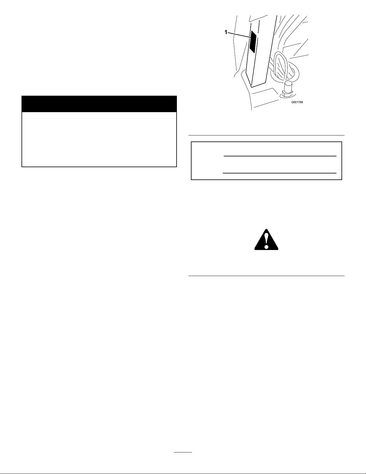
Figure1
1.Locationofthemodelandserialnumbers
ModelNo.
SerialNo.
Thismanualidentiespotentialhazardsandhas
safetymessagesidentiedbythesafetyalertsymbol
(Figure2),whichsignalsahazardthatmaycauseserious
injuryordeathifyoudonotfollowtherecommended
precautions.
Figure2
1.Safetyalertsymbol.
Thismanualusestwootherwordstohighlight
information.Importantcallsattentiontospecial
mechanicalinformationandNoteemphasizesgeneral
informationworthyofspecialattention.
Readthismanualcarefullytolearnhowtooperateand
maintainyourproductproperly.Theinformationinthis
manualcanhelpyouandothersavoidinjuryandproduct
damage.AlthoughTorodesignsandproducessafe
products,youareresponsibleforoperatingtheproduct
properlyandsafely.YoumaycontactTorodirectlyat
www.T oro.comforproductandaccessoryinformation,
helpndingadealer,ortoregisteryourproduct.
Wheneveryouneedservice,genuineToroparts,or
additionalinformation,contactanAuthorizedService
DealerorToroCustomerServiceandhavethemodel
andserialnumbersofyourproductready.Figure1
illustratesthelocationofthemodelandserialnumbers
ontheproduct.
©2011—TheT oro®Company
8111LyndaleAvenueSouth
Bloomington,MN55420
Contents
Introduction.................................................................2
Safety...........................................................................4
SafeOperatingPractices.......................................4
ChemicalSafety....................................................4
BeforeOperating.................................................5
WhileOperating...................................................5
Maintenance.........................................................7
SoundPower........................................................7
SoundPressure.....................................................7
Hand-ArmVibration............................................7
WholeBodyVibration..........................................7
SafetyandInstructionalDecals.............................8
Contactusatwww.T oro.com.
2
PrintedintheUSA.
AllRightsReserved
Page 3

Setup..........................................................................13
1InstallingtheAnti-siphonFill
Receptacle......................................................13
2InstallingtheSprayProMonitor.......................14
3CheckingtheBoomHingeSprings...................15
4AdjustingtheBoomstoLevel..........................16
5CompletingtheSetup:Learningmoreabout
yourproduct...................................................16
ProductOverview......................................................17
Controls.............................................................18
Specications.....................................................24
Operation...................................................................25
ThinkSafetyFirst...............................................25
BeforeDrivingtheSprayerfortheFirst
Time..............................................................25
Pre-StartingChecks............................................26
DrivingtheSprayer.............................................27
NewSprayerBreak-In........................................27
OperatingtheSprayer.........................................28
FillingtheFreshWaterTank...............................28
FillingtheSprayTank.........................................29
OperatingtheBooms.........................................29
Spraying.............................................................30
SprayingTips.....................................................30
CleaningtheSprayer...........................................30
CalibratingtheSprayProMonitor.......................33
CalibratingtheBoomBypassValves....................35
Pump.................................................................35
TransportingtheSprayer....................................36
TowingtheSprayer.............................................36
Maintenance...............................................................37
RecommendedMaintenanceSchedule(s)................37
DailyMaintenanceChecklist...............................38
NotationforAreasofConcern...........................39
PremaintenanceProcedures....................................40
JackingtheSprayer.............................................40
Lubrication.............................................................41
GreasingtheSprayer...........................................41
GreasingtheBoomHinges.................................42
GreasingtheActuatorRodBearings...................42
EngineMaintenance...............................................44
CheckingtheAirIntakeScreen...........................44
ServicingtheAirCleaner....................................44
ServicingtheEngineOil.....................................45
ChangingtheSparkPlugs...................................46
FuelSystemMaintenance.......................................47
ReplacingtheFuelFilter.....................................47
DrainingtheFuelTank.......................................47
ElectricalSystemMaintenance................................48
Fuses..................................................................48
ServicingtheBattery...........................................48
DriveSystemMaintenance.....................................51
InspectingtheWheels/Tires...............................51
AdjustingtheFrontWheelT oe-In.......................51
BrakeMaintenance.................................................52
CheckingtheBrakeFluid....................................52
InspectingtheBrakes.........................................52
AdjustingtheParkingBrake................................52
BeltMaintenance....................................................53
ServicingtheDriveBelt......................................53
AdjustingtheSteeringPumpBelt........................53
HydraulicSystemMaintenance...............................54
CheckingtheTransaxle/HydraulicFluid.............54
ChangingTransaxle/HydraulicFluid..................54
ReplacingtheHydraulicFilter............................55
SpraySystemMaintenance......................................55
InspectingtheHoses..........................................55
PumpMaintenance.............................................55
AdjustingtheBoomActuator.............................56
EmergencyManualOperationoftheBoom
Actuators.......................................................57
InspectingtheNylonPivotBushings...................57
Cleaning.................................................................58
CleaningtheFlowmeter......................................58
CleaningtheSuctionStrainer..............................58
Storage.......................................................................59
Troubleshooting.........................................................61
Schematics.................................................................65
3
Page 4

Safety
ChemicalSafety
Improperuseormaintenancebytheoperatororowner
canresultininjury.Toreducethepotentialforinjury,
complywiththesesafetyinstructionsandalwayspay
attentiontothesafetyalertsymbol,whichmeans
CAUTION,WARNING,orDANGER—personal
safetyinstruction.Failuretocomplywiththeinstruction
mayresultinpersonalinjuryordeath.
Supervisors,operators,andservicepersonsshouldbe
familiarwiththefollowingstandardsandpublications:
(Thematerialmaybeobtainedfromtheaddressshown).
•FlammableandCombustibleLiquidsCode:
ANSI/NFPA30
•NationalFireProtectionAssociation:
ANSI/NFPA#505;PoweredIndustrialTrucks
NationalFirePreventionAssociation
BarrymarchParkQuincy,Massachusetts
02269U .S.A.
•SAEJ2258LightUtilityV ehicles
SocietyofAutomotiveEngineers
SAEWorldHeadquarters400CommonwealthDrive
Warrendale,P A15096-0001
•ANSI/UL558;InternalCombustion
EnginePoweredIndustrialTrucks
AmericanNationalStandardsInstitute,Inc.
1430BroadwayNewYork,NewYork10018U.S.A.
orUnderwritersLaboratories333PngstenRoad
Northbrook,Illinois60062U.S.A.
SafeOperatingPractices
WARNING
Thesprayerisanoff-highwayvehicleonlyandis
notdesigned,equipped,ormanufacturedforuseon
publicstreets,roads,orhighways.
Supervisor’sResponsibilities
•Makesurethatoperatorsarethoroughlytrainedand
familiarwiththeOperator’sManual,EngineManual,
andalllabelsonthesprayer.
•Establishyourownspecialproceduresandwork
rulesforunusualoperatingconditions(e.g.slopes
toosteepforsprayeroperation).
WARNING
Chemical substances used in the spray system may
be hazardous and to xic to y ou, bystander s, animals,
plants, soils or other pr oper ty .
•Carefullyreadandfollowthechemical
warninglabelsandMaterialSafetyData
Sheets(MSDS)forallchemicalsusedand
protectyourselfaccordingtothechemical
manufacturer’srecommendations.Forexample,
useappropriatePersonalProtectiveEquipment
(PPE)includingfaceandeyeprotection,gloves,
orotherequipmenttoguardagainstpersonal
contactwiththechemical.
•Keepinmindthattheremaybemorethanone
chemicalusedandinformationoneachshould
beassessed.
R efuse to operate or w or k on the spray er if this
•
inf or mation is not a v aila ble!
•Beforeworkingonaspraysystemmakesurethe
systemhasbeentriplerinsedandneutralized
accordingtotherecommendationsofthe
chemicalmanufacturer(s).
•Verifythereisanadequatesupplyofcleanwater
andsoapnearby,andimmediatelywashoffany
chemicalsthatcontactyou.
•Obtainpropertrainingbeforeusingorhandling
chemicals.
•Usethecorrectchemicalforthejob.
•Followthechemicalmanufacturer’sinstructionsfor
thesafeapplicationofthechemical.
•Handlechemicalsinawellventilatedarea.
•Weargogglesandotherprotectiveequipmentas
instructedbythechemicalmanufacturer.Ensure
thataslittleskinaspossibleisexposedwhileusing
chemicals.
•Havecleanwateravailableespeciallywhenllingthe
spraytank.
•Donoteat,drink,orsmokewhileworkingwith
chemicals.
•Alwayswashyourhandsandotherexposedareasas
soonaspossibleafternishingthework.
•Properlydisposeofunusedchemicalsand
chemicalcontainersasinstructedbythechemical
manufacturerandyourlocalcodes.
•Chemicalsandfumesinthetanksaredangerous;
neverenterthetankorplaceyourheadoverorin
theopening.
4
Page 5

BeforeOperating
•Operatethemachineonlyafterreadingand
understandingthecontentsofthismanual.
•Neverallowchildrentooperatethesprayer.
•Neverallowotheradultstooperatethesprayer
withoutrstreadingandunderstandingtheOperator’ s
Manual.Onlytrainedandauthorizedpersonsshould
operatethissprayer.Makesurethatalloperators
arephysicallyandmentallycapableofoperatingthe
sprayer.
•Thissprayerisdesignedtocarryonlyyou,the
operator.Nevercarryanypassengersonthesprayer.
•Neveroperatethesprayerwhenundertheinuence
ofdrugsoralcohol.Evenprescriptiondrugsand
coldmedicinescancausedrowsiness.
•Donotdrivethesprayerwhenyouaretired.Besure
totakeoccasionalbreaks.Itisveryimportantthat
youstayalertatalltimes.
•Becomefamiliarwiththecontrolsandknowhowto
stoptheenginequickly.
•Keepallshields,safetydevices,anddecalsinplace.
Ifashield,safetydevice,ordecalismalfunctioning,
illegible,ordamaged,repairorreplaceitbefore
operatingthemachine.
•Alwayswearsubstantialshoes.Donotoperate
themachinewhilewearingsandals,tennisshoes,
orsneakers.Donotwearloosettingclothingor
jewelrywhichcouldgetcaughtinmovingpartsand
causepersonalinjury.
•Wearingsafetyglasses,safetyshoes,longpants,anda
helmetisadvisableandrequiredbysomelocalsafety
andinsuranceregulations.
•Avoiddrivingwhenitisdark,especiallyinunfamiliar
areas.Ifyoumustdrivewhenitisdark,besure
todrivecautiously ,usetheheadlights,andeven
consideraddingadditionallights.
•Beextremelycarefulwhenoperatingaroundpeople.
Alwaysbeawareofwherebystandersmightbeand
keepthemawayfromtheworkarea.
•Beforeoperatingthesprayer,alwayscheckthe
designatedareasofthesprayerthatarestatedin
thePre-StartingChecksintheOperationsection.
Ifthemachinedoesnotfunctioncorrectlyoris
damagedinanyway,donotusethesprayer.Make
surethattheproblemiscorrectedbeforethesprayer
orattachmentisoperated.
•Ensurethatalluidlineconnectorsaretightandall
hosesareingoodconditionbeforeapplyingpressure
tothesystem.
•Sincegasolineishighlyammable,handleitcarefully.
–Useanapprovedgasolinecontainer.
–Donotremovethecapfromthefueltankwhen
theengineishotorrunning.
–Donotsmokewhilehandlinggasoline.
–Fillthefueltankoutdoors,andllittoabout
1inch(25mm)belowthetopofthetank(the
bottomofthellerneck).Donotoverllit.
–Wipeupanyspilledgasoline.
WhileOperating
WARNING
Engineexhaustcontainscarbonmonoxide,which
isanodorless,deadlypoisonthatcankillyou.
Donotrunengineindoorsorinanenclosedarea.
•Theoperatorshouldremainseatedwheneverthe
sprayerisinmotion.Theoperatorshouldkeepboth
handsonthesteeringwheelwheneverpossible.
Keepyourarmsandlegswithinthesprayerbody
atalltimes.
•Alwayswatchoutforandavoidlowoverhangssuch
astreelimbs,doorjambs,andoverheadwalkways.
Makesurethereisenoughroomoverheadtoeasily
clearthesprayerandyourhead.
•Failuretooperatethesprayersafelymayresultinan
accident,tipoverofthesprayer,andseriousinjury
ordeath.Drivecarefully.Topreventtippingorloss
ofcontrol:
–Useextremecaution,reducespeed,andmaintain
asafedistancearoundsandtraps,ditches,creeks,
ramps,unfamiliarareas,oranyareasthathave
abruptchangesingroundconditionsorelevation.
–Watchforholesorotherhiddenhazards.
–Useextracautionwhenoperatingthesprayeron
wetsurfaces,inadverseweatherconditions,at
higherspeeds,orwithafullload.Stoppingtime
anddistancewillincreasewithafullload.
–Avoidsuddenstopsandstarts.Donotgofrom
reversetoforwardorforwardtoreversewithout
rstcomingtoacompletestop.
–Slowdownbeforeturning.Donotattempt
sharpturnsorabruptmaneuversorotherunsafe
drivingactionsthatmaycausealossofsprayer
control.
–Beforebackingup,looktotherearandensure
thatnooneisbehindyou.Backupslowly.
–Watchoutfortrafcwhenyouarenearor
crossingroads.Alwaysyieldtherightofway
5
Page 6

topedestriansandothervehicles.Thissprayer
isnotdesignedforuseonstreetsorhighways.
Alwayssignalyourturnsorstopearlyenough
sothatotherpeopleknowwhatyouplantodo.
Obeyalltrafcrulesandregulations.
–Theelectricalandexhaustsystemsofthesprayer
canproducesparkscapableofignitingexplosive
materials.Neveroperatethesprayerinornear
anareawherethereisdustorfumesintheair
whichareexplosive.
–Ifyouareeverunsureaboutsafeoperation,stop
workandaskyoursupervisor.
•Donottouchtheengineormuferwhiletheengine
isrunningorsoonafterithasstopped.Theseareas
maybehotenoughtocauseburns.
•Ifthemachineevervibratesabnormally,stop
immediately,waitforallmotiontostop,andinspect
thesprayerfordamage.Repairalldamagebefore
resumingoperation.
•Beforegettingoffoftheseat:
1.Stopthemovementofthemachine.
2.PlacetherangeselectorinNeutralandsetthe
parkingbrake.
3.TurntheignitionkeytoOff.
4.Removetheignitionkey.
Important:Donotparkthemachineonan
incline.
•Lightningcancausesevereinjuryordeath.If
lightningisseenorthunderisheardinthearea,do
notoperatethemachine;seekshelter.
Braking
•Slowdownbeforeyouapproachanobstacle.This
givesyouextratimetostoporturnaway.Hittingan
obstaclecandamagethesprayeranditscontents.
Moreimportant,itcaninjureyou.
•GrossVehicleWeight(GVW)hasamajorimpacton
yourabilitytostopand/orturn.Heavyloadsand
attachmentsmakeasprayerhardertostoporturn.
Theheaviertheload,thelongerittakestostop.
•Turfandpavementaremuchmoreslipperywhen
theyarewet.Itcantake2to4timesaslongtostop
onwetsurfacesasondrysurfaces.Ifyoudrive
throughstandingwaterdeepenoughtogetthe
brakeswet,theywillnotworkwelluntiltheyare
dry.Afterdrivingthroughwater,youshouldtestthe
brakestomakesuretheyworkproperly.Iftheydo
not,driveslowlywhileputtinglightpressureonthe
brakepedal.Thiswilldrythebrakesout.
OperatingonHillsandRoughTerrain
Operatingthesprayeronahillmaycausetippingor
rollingofthesprayer,ortheenginemaystallandyou
couldloseheadwayonthehill.Thiscouldresultin
personalinjury.
•Donotacceleratequicklyorslamonthebrakes
whenbackingdownahill,especiallywithaload.
•Neverdriveacrossasteephill;alwaysdrivestraight
upordownorgoaroundthehill.
•Iftheenginestallsoryoubegintoloseheadway
whileclimbingahill,graduallyapplythebrakesand
slowlybackstraightdownthehill.
•Turningwhiletravelingupordownhillscanbe
dangerous.Ifyouhavetoturnwhileonahill,do
itslowlyandcautiously.Nevermakesharporfast
turns.
•Heavyloadsaffectstability.Reducetheweightofthe
loadandyourspeedwhenoperatingonhills.
•Avoidstoppingonhills,especiallywithaload.
Stoppingwhilegoingdownahillwilltakelonger
thanstoppingonlevelground.Ifthesprayermust
bestopped,avoidsuddenspeedchanges,whichmay
initiatetippingorrollingofthesprayer.Donotslam
onthebrakeswhenrollingbackward,asthismay
causethesprayertooverturn.
•TheToroCompanystronglyrecommendsinstalling
theoptionalROPSKitwhenoperatingonhilly
terrain.IfyouinstallaROPS,alwaysweartheseat
beltwhendrivingthesprayer.
•Reducespeedandloadwhenoperatingonrough
terrain,unevenground,andnearcurbs,holes,and
othersuddenchangesinterrain.Loadsmayshift,
causingthesprayertobecomeunstable.
WARNING
Suddenchangesinterrainmaycauseabrupt
steeringwheelmovement,possiblyresultingin
handandarminjuries.
•Reduceyourspeedwhenoperatingonroughterrain
andnearcurbs.
•Gripthesteeringwheellooselyaroundtheperimeter.
Keepyourhandsclearofthesteeringwheelspokes.
Loading
Theweightofthecargocanchangethesprayercenter
ofgravityandsprayerhandling.Toavoidlossofcontrol
andpersonalinjury,followtheseguidelines:
6
Page 7

•Reducetheweightoftheloadwhenoperating
onhillsandroughterraintoavoidtippingor
overturningofthesprayer.
•Liquidloadscanshift.Thisshiftinghappensmost
oftenwhileturning,goingupordownhills,suddenly
changingspeeds,orwhiledrivingoverrough
surfaces.Shiftingloadscancausethesprayertotip
over.
•Whenoperatingwithaheavyload,reduceyour
speedandallowforsufcientbrakingdistance.Do
notsuddenlyapplythebrakes.Useextracautionon
slopes.
•Beawarethatheavyloadsincreaseyourstopping
distanceandreduceyourabilitytoturnquickly
withouttippingover.
accessories.Replacementpartsandaccessoriesmade
byothermanufacturerscouldbedangerous.Altering
thissprayerinanymannerthatmayaffectsprayer
operation,performance,durability,oritsuse,may
resultininjuryordeath.Suchusecouldvoidthe
productwarranty.
SoundPower
Thisunithasaguaranteedsoundpowerlevelofof96
dBA,whichincludesanUncertaintyValue(K)of1dBA.
Soundpowerlevelwasdeterminedaccordingtothe
proceduresoutlinedinISO11094.
SoundPressure
Maintenance
•Onlypermitqualiedandauthorizedpersonnelto
maintain,repair,adjust,orinspectthesprayer.
•Beforeservicingormakingadjustmentstothe
machine,stoptheengine,settheparkingbrake,
andremovethekeyfromtheignitiontoprevent
someonefromaccidentallystartingtheengine.
•Tomakesurethattheentiremachineisingood
condition,keepallnuts,bolts,andscrewsproperly
tightened.
•Toreducethepotentialforre,keeptheengine
areafreeofexcessivegrease,grass,leaves,and
accumulationofdirt.
•Neveruseanopenametocheckthelevelor
leakageoffuelorbatteryelectrolyte.
•Iftheenginemustberunningtoperforma
maintenanceadjustment,keepyourhands,feet,
clothing,andanypartsofyourbodyawayfromthe
engineandanymovingparts.Keepeveryoneaway.
•Donotuseopenpansoffuelorammablecleaning
uidswhencleaningparts.
•Donotadjustthegroundspeedgovernor.To
ensuresafetyandaccuracy,haveanAuthorizedToro
Distributorcheckthegroundspeed.
•Keepyourbodyandhandsawayfrompinhole
leaksornozzlesthatejecthighpressureuid.Use
cardboardorpapertondleaks.Fluidescaping
underpressurecanpenetrateskinandcauseinjury
requiringsurgerywithinafewhoursbyaqualied
surgeonorgangrenemayresult.
•Ifmajorrepairsareeverneededorassistanceis
required,contactanAuthorizedToroDistributor.
•Tobesureofoptimumperformanceandsafety,
alwayspurchasegenuineTororeplacementpartsand
Thisunithasasoundpressurelevelattheoperator’s
earof83dBA,whichincludesanUncertaintyValue(K)
of1dBA.
Soundpressurelevelwasdeterminedaccordingtothe
proceduresoutlinedinENISO11201.
Hand-ArmVibration
Measuredvibrationlevelforrighthand=1.00m/s
Measuredvibrationlevelforlefthand=0.90m/s
UncertaintyValue(K)=0.5m/s
Measuredvaluesweredeterminedaccordingtothe
proceduresoutlinedinEN1032.
2
WholeBodyVibration
Measuredvibrationlevel=0.2m/s
UncertaintyValue(K)=0.5m/s
Measuredvaluesweredeterminedaccordingtothe
proceduresoutlinedinEN1032.
2
2
2
2
7
Page 8
SafetyandInstructionalDecals
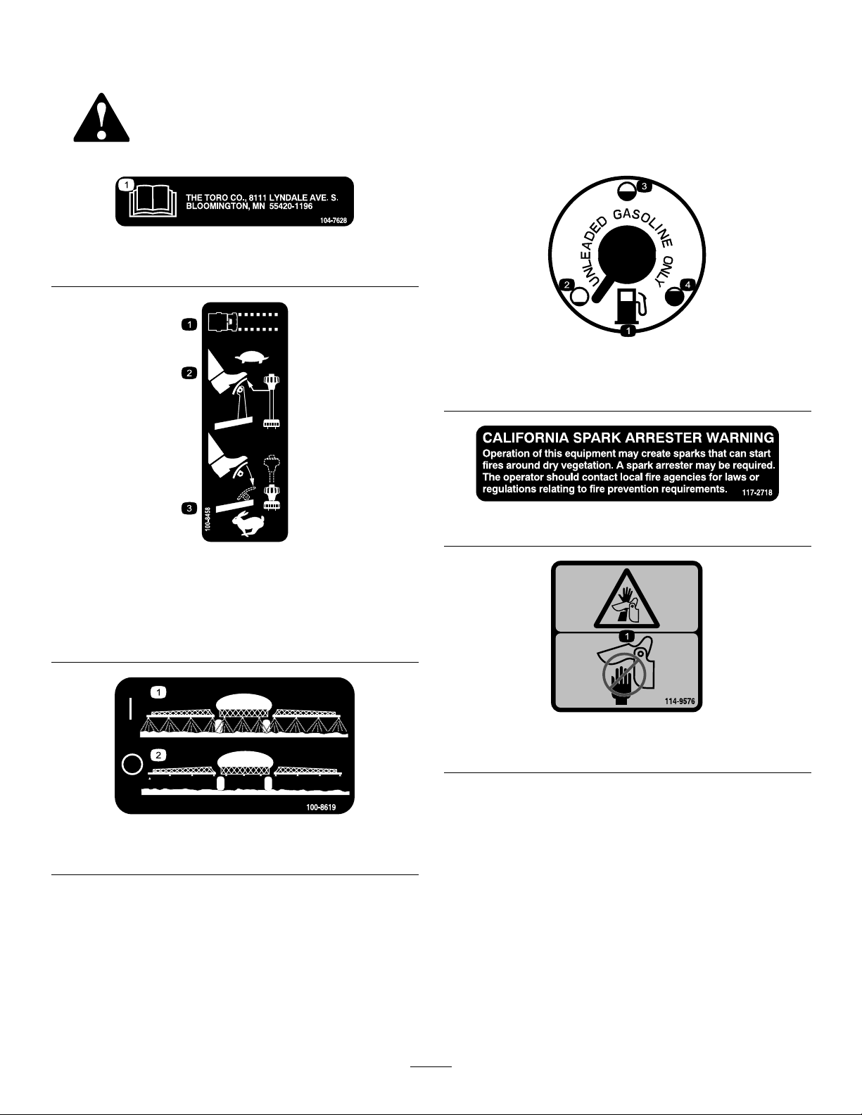
Safetydecalsandinstructionsareeasilyvisibletotheoperatorandarelocatednearanyareaof
potentialdanger.Replaceanydecalthatisdamagedorlost.
104-7628
1.ReadtheOperator’sManual.
100-8386
1.Fuel
2.Empty4.Full
3.Half-full
100-8458
1.Machinespeed
2.Tosetthemachinetoaslowspeed,reducepressureonthe
acceleratorandpulluponthespeedlimiter.
3.Tosetthemachinetoafastspeed,presstheaccelerator
pedalandpushdownonthespeedlimiter.
100-8619
1.Sprayon2.Sprayoff
117–2718
114-9576
1.Pinchpoint,hand—keephandawayfromhinge.
8
Page 9
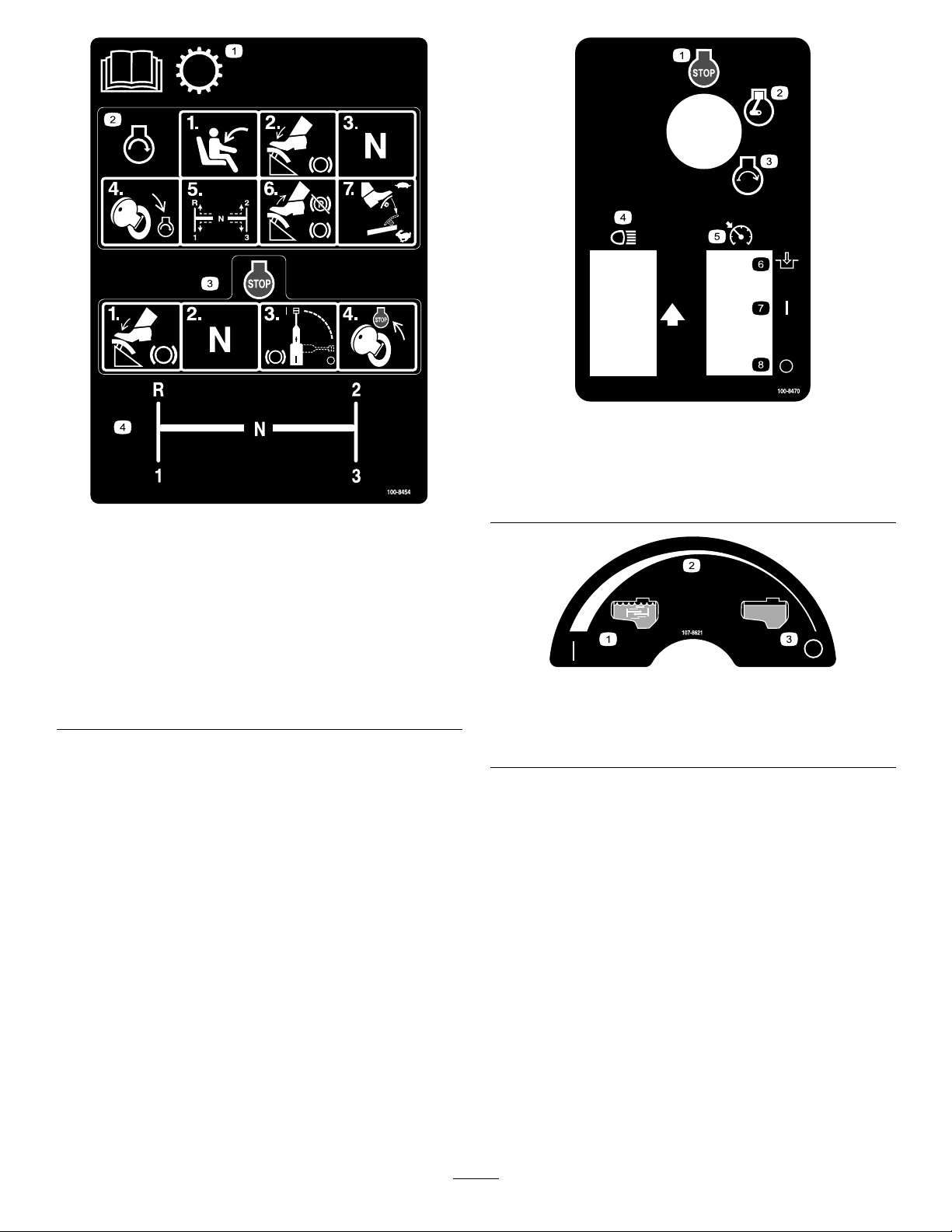
100-8454
1.ReadtheOperator’sManualforinformationonthe
transmission.
2.Tostarttheengine,sitontheoperator’sseat,pressthe
brake,settherangeselectortoNeutral,turntheignition
keytoEngine-start,settherangeselectortothedesired
gear,releasethebrakeandparkingbrake,andpressthe
acceleratorpedaltothedesiredspeed.
3.Tostoptheengine,pressthebrake,settherangeselector
toNeutral,settheparkingbrake,andturntheignitionkey
toEngine-stop.
4.Rangeselectorgearpattern
100-8470
1.Engine—stop5.Neutralenginespeedlock
2.Engine—run6.Engage
3.Engine—start
4.Headlights
7.On
8.Off
107-8621
1.Agitationon
2.Continuousvariable
setting
3.Agitationoff
9
Page 10
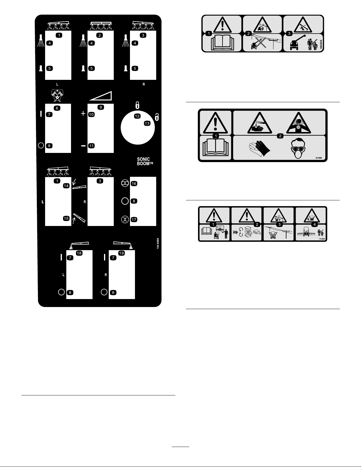
106-5016
1.Warning—readtheOperator’sManual.
2.Electricshockhazard,overheadpowerlines—stayaway
fromoverheadpowerlines.
3.Crushinghazard,boom—keepbystandersasafedistance
fromthemachine.
93-0688
1.Warning—readtheOperator’sManual.
2.Causticliquid/chemicalburnandtoxicgasinhalation
hazards—wearhand,skin,eye,andrespiratoryprotection.
100-8489
1.Leftboom
2.Centerboom
3.Rightboom13.Unlocked
4.Sprayon
5.Sprayoff
6.Pump16.Automatic
7.On
8.Off18.Leftboomfoammarker
9.Continuousvariable
setting,spraypressure
10.Increase
11.Decrease
12.Locked
14.Lowertheboom.
15.Raisetheboom.
17.Manual
19.Rightboomfoammarker
110-5240
1.Warning—readtheOperator’sManualandreceivetraining
beforeoperating.
2.Warning—stayawayfrommovingparts,donotoperate
withcoversremoved.
3.Electricshockhazard,overheadpowerlines—stayaway
fromoverheadpowerlines.
4.Crushinghazard,boom—keepbystandersasafedistance
fromthemachine.
10
Page 11

110-5143
1.Warning—readtheOperator’sManual.
2.TippingHazard—driveslowlyoverroughterrainandwhen
turning.
3.Fallingandarm/leginjuryhazards—donotcarrypassengers
andkeeparmsandlegsinsideofthevehicleatalltimes.
4.Tostoptheengine,pressthebrake,movetherange
selectortoNeutral,settheparkingbrake,releasethebrake
pedal,turntheignitionkeytoEngine-stop,andremovethe
key.
106-5051
1.Warning—readtheOperator’sManual;usefresh,clean
waterforrst-aidwashing.
108-3307
107-8640
1.Warning—readtheOperator’sManual;usefresh,clean
waterforrinsingthetank.
106-1355
1.Warning—donotenterthetank.
1.Totalarea8.Width
2.Boomselect9.Distance
3.Speed10.Speedcalibration
4.Unitsofmeasure11.Subvolume
5.Selectunits
6.Applicationrate13.Flowmetercalibration
7.Subarea
11
108-3309
12.Totalvolume
Page 12
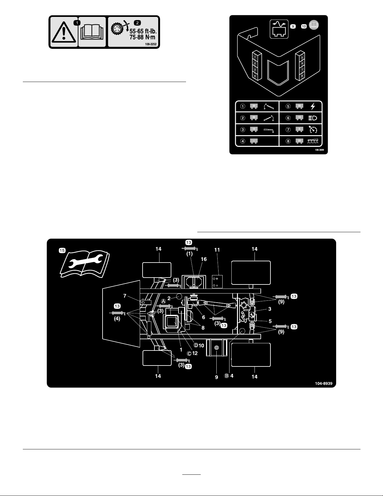
1.Warning—readthe
Operator’sManual.
108-3252
2.Torquelugnutsto55-65
ft-lb(75-88N·m).
108-3699
1.30ampfuse,leftboom
actuator
2.30ampfuse,rightboom
actuator
3.15ampfuse,foammarker8.20ampfuse,spraysystem
4.Empty9.Fusepanel
5.30ampfuse,power10.ReadtheOperator’s
6.10ampfuse,headlights
7.5ampfuse,cruisecontrol
Manualformore
information.
104-8939
1.Engineoillevel(dipstick)
2.Engineoillter6.Gearboxuidlevel10.Fuellter
3.Transaxle/hydraulicuid
level(dipstick)
4.Transaxlehydrauliclter
5.Hydraulicstrainer9.Fuel,unleadedonly
7.Brakeuid
8.Belts,steeringanddrive12.Aircleaner16.Pump
11.Battery15.Readtheinstructions
12
13.Grease
14.Tirepressure
beforeservicingor
performingmaintenance.
Page 13

Setup
LooseParts
Usethechartbelowtoverifythatallpartshavebeenshipped.
ProcedureDescription
1
2
3
4
5
90degreetting
Quickcoupler
Hoseadapter1
Fillreceptaclebracket1
Flange-headbolt,5/16x3/4inch
Anti-siphonhose1
SprayProMonitor
SprayProDecal
Bracket1
Flange-headbolt,3/4inch
Flangenut,1/4inch
Knob2
Washer2
Carriagebolt
Nopartsrequired
Nopartsrequired
Ignitionkey1
Operator’sManual
EngineOperator’sManual
PartsCatalog
OperatorTrainingMaterial
RegistrationCard
Pre-deliveryInspectionSheet
Qty.
Use
1
1
Installtheanti-siphonllreceptacle.
1
1
1
2
2
2
–
–
1
1
1
1
1
1
InstalltheSpray-Promonitor.
Checktheboomhingesprings.
Adjusttheboomstolevel.
Readthemanualsandviewthetraining
materialbeforeoperatingthemachine.
Note:Determinetheleftandrightsidesofthemachine
fromthenormaloperatingposition.
13
Page 14

1
InstallingtheAnti-siphonFill
Receptacle
Partsneededforthisprocedure:
1
90degreetting
1
Quickcoupler
1Hoseadapter
1Fillreceptaclebracket
1
Flange-headbolt,5/16x3/4inch
1Anti-siphonhose
4.Locktheadapterintoplacebyswingingthelevers
towardtheadapterandthensecurethemwiththe
hairpincotters(Figure3).
5.Installtheanti-siphonhosethroughthelarge
openingonthebracketandontothebarbedendof
the90degreeelbowtting(
Important:Donotlengthenthehosetoallow
contactwiththetankuids.
Figure3).
2
InstallingtheSprayPro
Monitor
Procedure
1.Placethellreceptaclebracketoverthethreaded
holeinthetankandsecureitwithaange-headbolt
(5/16x3/4inch)(Figure3).
Figure3
1.Fillreceptaclebracket
2.Threadedholeinthetank6.Hoseadapter
3.Flangebolt,5/16x3/4inch
4.90degreeelbowtting
5.Quickcoupler
7.Anti-siphonhose
Partsneededforthisprocedure:
1
SprayProMonitor
1
SprayProDecal
1Bracket
2
Flange-headbolt,3/4inch
2
Flangenut,1/4inch
2Knob
2Washer
2
Carriagebolt
Procedure
1.InstalltheSprayProDecaltothemonitor(Figure4).
2.Placethethreadedendofthe90degreeelbowtting
throughthebracketandthreadthequickcoupler
ontoit,securingittothebracket(Figure3).
Note:Installthettingwiththeopenendpointing
towardthelargeopeninginthebracketandtoward
thetankopeningsothewaterwillarcintothetank
whenyoullit.
3.Installthehoseadapterintothequickcoupler
(
Figure3).
Figure4
1.Spraypromonitor3.Decal,Lowerhalf
2.Decal,Upperhalf
Note:Besuretoorientthedecalasshownin
Figure20.
2.Installthemonitorbracketonthedash(
using2ange-headbolts(1/4x3/4inch)and2
angenuts(1/4inch).
14
Figure5)
Page 15

Figure5
1.SprayPromonitor
2.Bracket4.Knob
3.Looselyinstallthe2carriagebolts,rubber
washers,andknobsonthebracketasillustratedin
FigureFigure5andFigure6.
3.Flange-headbolts,
1/4x3/4inch
1.Connectorsfromthe
sprayer
3
Figure7
2.Connectorsfromthe
monitor
Note:Installthecarriageboltsandrubberwashers
insideofthebracketandtheknobsontheoutside.
Figure6
1.Carriagebolt
2.Rubberwasher4.Bracket
4.Removethelargegrommetfromtheholeinthedash
andthreadthecablesonthemonitorthroughthe
grommetandthedash.
5.Installthegrommetintothedash.
6.InstalltheSprayPromonitoroverthecarriagebolt
heads(Figure5)andtightentheknobstosecureit.
7.ConnecttheSprayProwireconnectorstothewire
connectorslocatedunderthedash(Figure7).
3.Knob
CheckingtheBoomHinge
Springs
NoPartsRequired
Procedure
Important:Operatingthespraysystemwith
theboomhingespringsundertheincorrect
compressioncoulddamagetheboomassembly .
Measurethespringsandusethejamnutto
compressthespringsto1.56inchesifnecessary.
Thesprayerisshippedwiththeboomextensionsswung
forwardtofacilitatepackagingofthemachine.The
springsarenotfullytightenedatthetimeofmanufacture
toallowtheboomstobeinthispositionfortransit.
Beforeoperatingthemachine,thespringsmustbe
adjustedtothecorrectcompression.
1.Ifnecessary,removethepackingcomponentsthat
securetherightandleftextensionboomsduring
shipping.
2.Supporttheboomswhiletheyareextendedtothe
sprayposition.
3.Attheboomhinge,measurethecompressionofthe
upperandlowerspringswhiletheboomsareintheir
extendedposition(
A.Allspringsmustbecompresseduntilthey
measure1.56inches.
Figure8).
15
Page 16
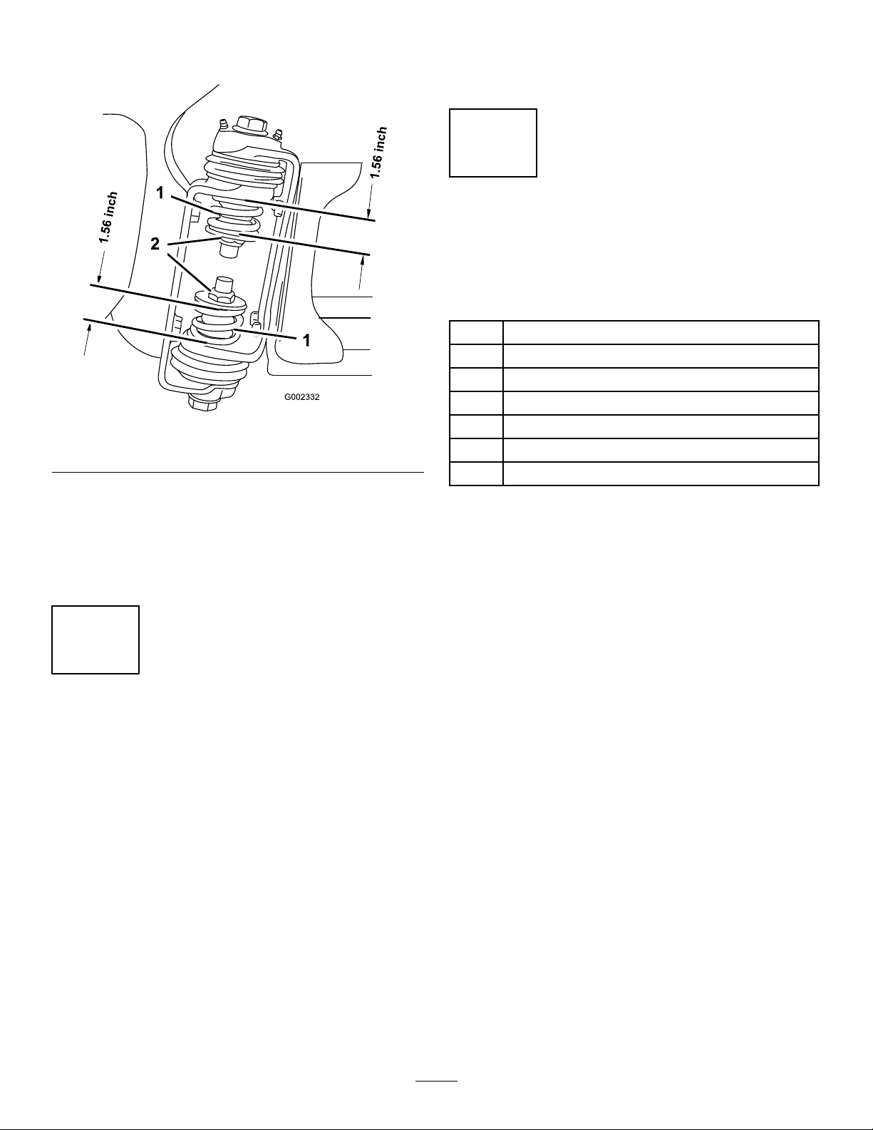
B.Usethejamnuttocompressanyspringthat
measuregreaterthan1.56inches.
Figure8
1.Boomhingespring2.Jamnut
4.Repeattheprocedureforeachspringonbothboom
hinges.
5.Movetheboomsintothetransport“X”position.
SeeOperatingtheBoomsintheOperationsection
formoreinformation.
Note:Thebumpermayexperiencesomecompression
overtime.Iftheboomsdropbelowlevel,usethis
proceduretoreadjustthebumperpositionneeded.
5
CompletingtheSetup:
Learningmoreaboutyour
product.
Partsneededforthisprocedure:
1Ignitionkey
1
Operator’sManual
1
EngineOperator’sManual
1
PartsCatalog
1
OperatorTrainingMaterial
1
RegistrationCard
1
Pre-deliveryInspectionSheet
Procedure
1.Readthemanuals.
2.ViewtheOperatortrainingmaterial.
4
AdjustingtheBoomstoLevel
NoPartsRequired
Procedure
1.Attheoperator’ sposition,turntheignitionkeyto
Ontoenergizethesystem.
2.Movetheboomsintopositionsothattheyarelevel
withtheground.
3.Removethekeyandexittheoperator’sposition.
4.Atthehinge,adjustthepositionofthebumpersso
theboomcannotmovepastlevelwiththeground.
Takecaretomakesurethebumperislevel.
5.Tightentheboltandnuttolockthebumpersintothe
adjustedposition.T orquethefastenersto135-165
ft-lbs(183-223N-m).
3.CompletetheregistrationcardandreturntoToro.
4.Storethedocumentationinasafeplace.
16
Page 17
ProductOverview
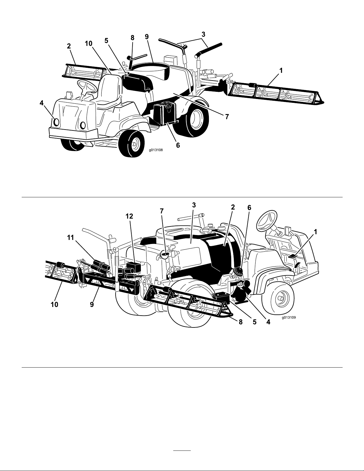
g013108
g013109
Figure9
1.Leftboom
2.Rightboom5.Freshwatertank
3.Boomtransportcable6.Fueltank9.Tanklid
4.Headlight
7.Chemicaltank10.Operator’sposition
8.Anti-SiphonReceptacle
Figure10
1.Pedals4.Pump7.Agitationcontrolvalve
2.Rinsetank5.Battery8.Rightboom11.Boomcontrolcylinder
3.Chemicaltank
6.Pumppressuredampener
17
9.Centerboom
10.Leftboom
12.Valvecluster
Page 18
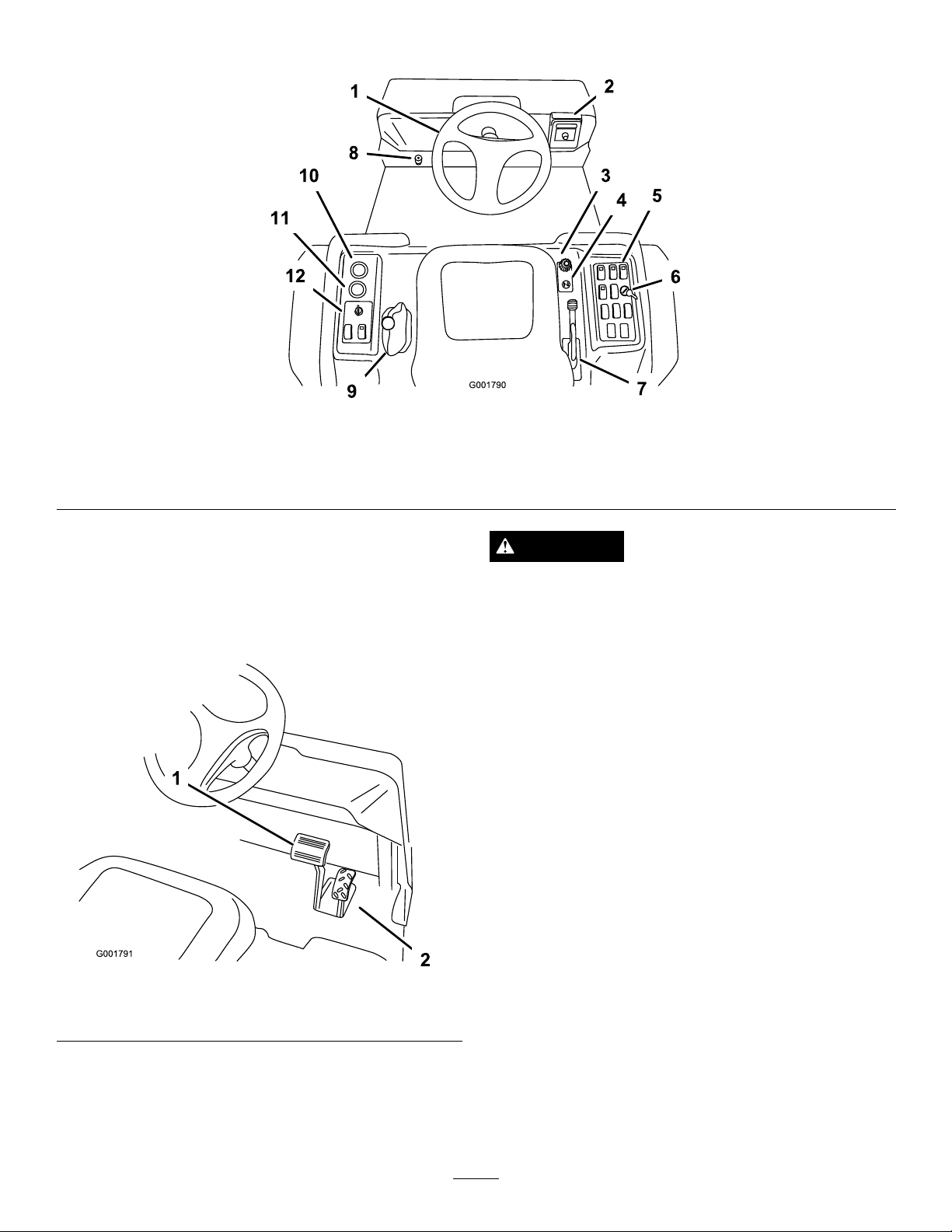
Controls
Figure11
1.Steeringwheel4.Choke
2.Spray-Promonitor5.Sprayercontrols8.Masterboomfootswitch
3.Speedlimiter
6.Ratelockoutswitch
7.Parkingbrake10.Voltmeter
9.RangeSelector
11.Hourmeter
12.Vehiclecontrols
AcceleratorPedal
Theacceleratorpedal(Figure12)givesyoutheabilityto
varygroundspeedofthesprayer.Pressingthepedal
increasesgroundspeed.Releasingthepedalwillslow
thesprayerandtheenginewillidle.
Figure12
1.Brakepedal2.Acceleratorpedal
CAUTION
Brakescanbecomewornorcanbeadjusted
incorrectlyresultinginpersonalinjury .
Ifbrakepedaltravelstowithin1inch(2.5cm)ofthe
sprayeroorboard,thebrakesmustbeadjusted
orrepaired.
ParkingBrake
Theparkingbrakeisalargelevertotherightoftheseat.
(Figure13).Engagetheparkingbrakewheneveryou
planonleavingtheseattopreventaccidentalmovement
ofthesprayer.Toengagetheparkingbrake,pullupand
backonthelever.Todisengage,pushitforwardand
down.Ifthesprayerisparkedonasteepgrade,apply
theparkingbrakeandplaceblocksatthedownhillside
ofthewheels.
BrakePedal
Usethebrakepedaltostoporslowthesprayer
(Figure12).
18
Page 19
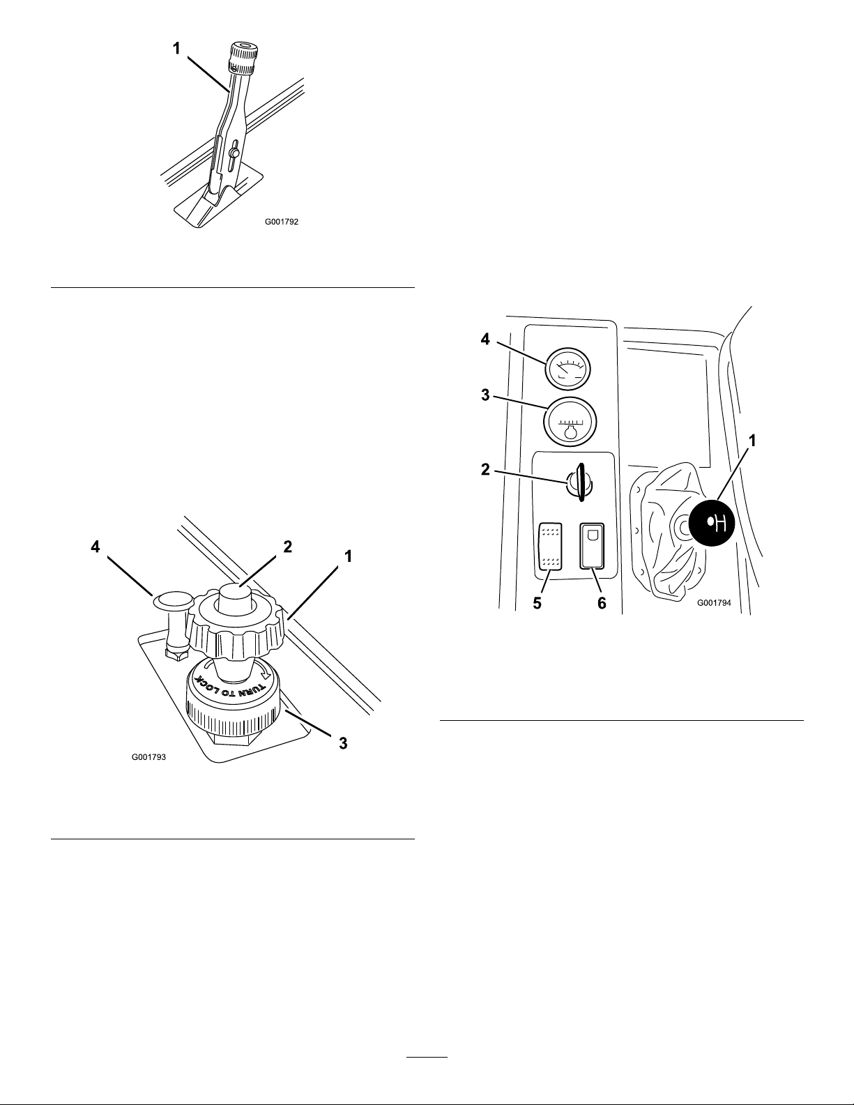
Figure13
1.Parkingbrakelever
SpeedLimiter
Thespeedlimiterisalargeknoblocatedtotherightof
theseat(Figure14).Itallowsyoutosetthemaximum
downwardtraveloftheacceleratorpedal,thereby
limitingthemaximumrpmoftheengine.Thisindirectly
limitsthespeedofthesprayer.
RangeSelector
Therangeselector,locatedtotheleftoftheseat,has
5positions:3forwardspeeds,Neutral,andReverse
Figure15).Theenginewillstartonlywhentherange
(
selectorisintheNeutralposition.Youmustalsofully
pressthebrakewiththesprayerstoppedtochange
ranges.
Important:Donotshiftoutoforchangeranges
whilethevehicleismoving.Attemptingtochange
rangeswhilethevehicleismovingcandamagethe
transmission.Onlystoppingthesprayercompletely,
andfullyengagingthebrakewillsafelydisengage
thelockingpinandallowtherangestobechanged.
Note:Thevehiclecontrolstheapplicationratebased
onyourspeedandyoudonotneedtokeepaconstant
speedtoapplyataconstantrate.
Figure14
1.Speedlimiterknob
2.Speedlimiterbutton4.Chokecontrol
3.Lockingring
ChokeControl
Figure15
1.RangeSelector
2.Ignitionswitch5.Headlightswitch
3.Hourmeter6.Neutralenginespeedlock
4.Voltmeter
switch
IgnitionSwitch
Theignitionswitch(Figure15),usedtostartandstop
theengine,has3positions:Stop,Run,andStart.Rotate
thekeyclockwisetotheStartpositiontostarttheengine
andreleaseittotheRunpositionwhenstarted.Rotate
thekeytotheStoppositiontostoptheengine.
Thechokecontrolisasmallknobtotherightofthe
seat.(Figure14).Tostartacoldengine,pullthechoke
controlup.Aftertheenginestarts,regulatethechoketo
keeptheenginerunningsmoothly.Assoonaspossible,
pushthecontroldowntotheOffposition.Awarm
enginerequireslittleornochoking.
HourMeter
Thehourmeter(Figure15)indicatesthetotalnumber
ofhourstheenginehasrun.Thehourmeterstartsto
functionwheneverthekeyisturnedtotheRunposition.
19
Page 20
Voltmeter
BoomSwitches
Thevoltmeter(Figure15)indicatesthelevelofcharge
inthebattery.Whenthebatteryisfullycharged,the
voltmeterwillreadinthecenterofthedialwhenthe
keyisintheRunpositionwiththeengineoff.When
theengineisrunningthevoltmeterneedleshouldbe
totheright.
HeadlightSwitch
Toggletheswitchtooperatetheheadlights(Figure15).
Pushitforwardtoturnthelightsonandrearwardto
turnthemoff.
NeutralEngineSpeedLockSwitch
WhentherangeselectorisintheNeutralposition,you
canusetheacceleratorpedaltospeeduptheengine,
thenpushthisswitchforwardtosettheengineatthat
speed.Thisisnecessarytorunthechemicalagitation
whilestationaryoroperatingattachmentssuchasthe
handsprayer(
Important:Therangeselectormustbeinthe
neutralpositionfortheswitchtowork.
Figure15).
Theboomswitchesarelocatedatthefrontofthe
controlpaneltotherightoftheseat(
Figure17).Toggle
eachswitchforwardtoturnthecorrespondingboom
sectiononandrearwardtoturnthemoff.Whenthe
switchisturnedon,alightontheswitchilluminates.
Theseswitcheswillonlyaffectthespraysystemwhen
themasterboomswitchison.
FuelGauge
Thefuelgaugeislocatedontopofthefueltank,on
therightsideofthemachineandshowstheamountof
fuelinthetank.
MasterBoomSwitch
Themasterboomswitchislocatedontheoorboard
ofthemachinecabandtotheleftoftheoperator.It
allowsyoutostartorstopthesprayoperation.Press
theswitchwithyourfoottoenableordisablethespray
system(
SprayPromonitorscreenreads“Hold."
Figure16).Whenthemasterswitchisoff,the
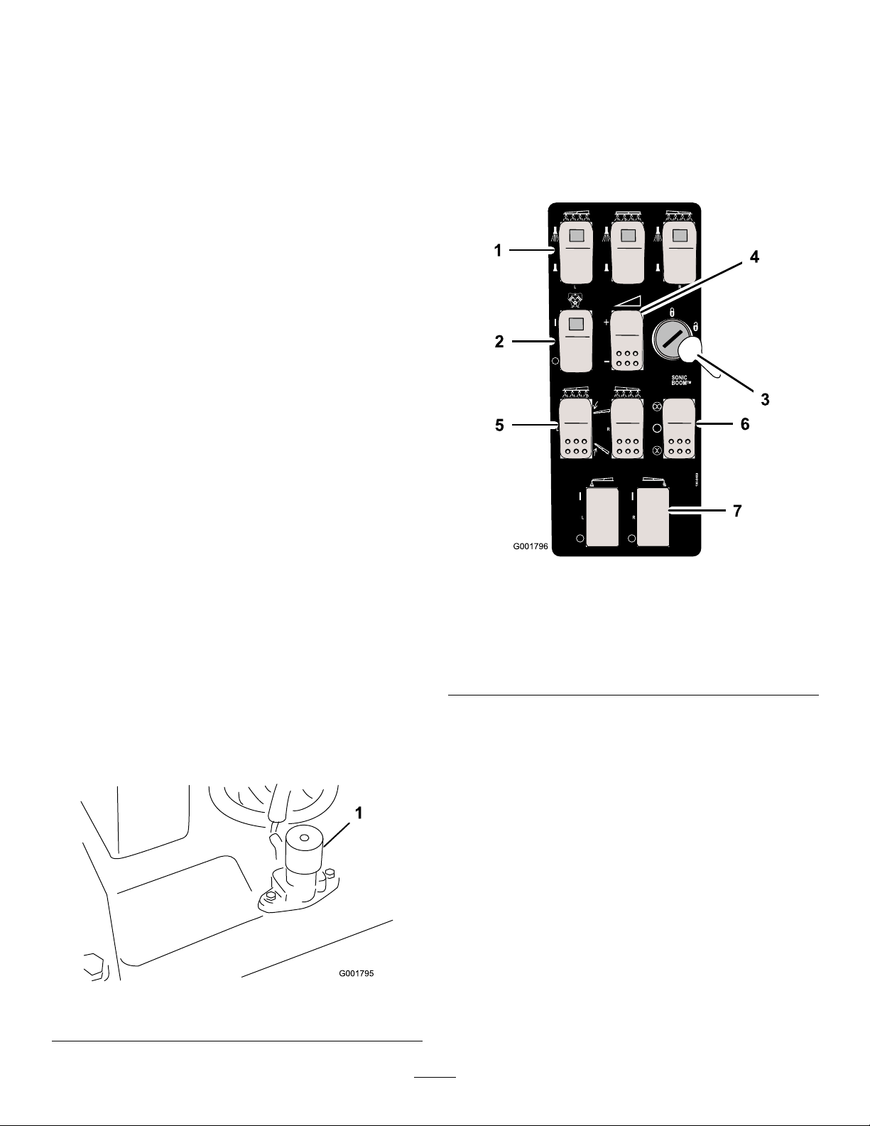
Figure17
1.Boomswitches,left,right
andcenter
2.Pumpswitch
3.Ratelockoutkey
4.Applicationrateswitch
5.Boomliftswitch,leftand
right
6.Sonicboomswitch
7.Foammarkerswitch,left
andright
PumpSwitch
Thepumpswitchislocatedonthecontrolpaneltothe
rightoftheseat(Figure17).T ogglethisswitchforward
torunthepumporrearwardtostopthepump.
Important:Onlyengagethepumpswitchwhen
theengineisatlowidletoavoiddamagingthe
pumpdrive.
ApplicationRateSwitch
1.Masterboomswitch
Figure16
Theapplicationrateswitchislocatedonthecontrol
paneltotherightoftheseat(Figure17).Pressandhold
theswitchforwardtoincreasethespraysystempressure,
orpressandholditrearwardtodecreasepressure.
20
Page 21
RateLockoutKeySwitch
G0131 13
1 2
3
Theratelockoutkeyswitchislocatedonthecontrol
paneltotherightoftheseat(
Figure17).Turnthekey
counterclockwisetothelockedpositiontodisablethe
applicationrateswitch,therebykeepinganyonefrom
accidentallychangingtheapplicationrate.Turnthe
keyclockwisetotheunlockedpositiontoenablethe
applicationrateswitch.
Important:Donotattempttomovetherange
selectorwhiletheratelockoutkeyisengaged.
Forcingtheselectorwhilemovingwilldamage
lockoutkeycomponents.
BoomLift
Theboomliftswitchesareusedtoraisetheleftand
rightboomrespectively .
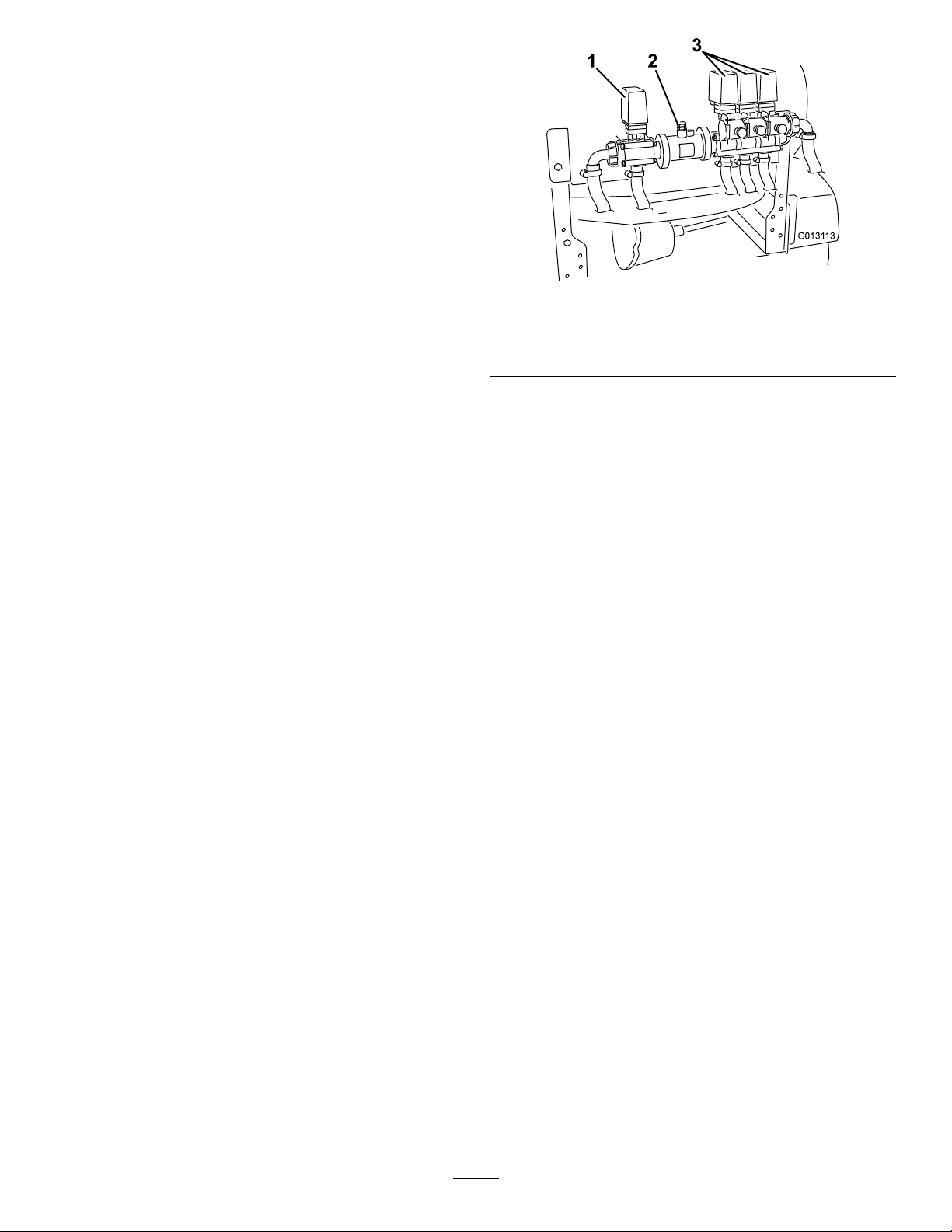
1.Regulating(ratecontrol)
valve
2.Flowmeter
Flowmeter
Figure18
3.Boomvalves
SonicBoom(Optional)
TheSonicBoomswitchisarockerswitchusedto
operatetheSonicBoom.Toggleswitchforwardfor
automatic,rearwardformanualandcenterforOff.
FoamMarkerSwitchLocations
(Optional)
Ifyouinstalltheelectricboomlift,sonicboom,and
foammarkerkit,youwilladdswitchestothecontrol
panelforcontrollingtheiroperation.Thesprayercomes
withplasticplugsintheselocations.
Regulating(RateControl)Valve
Thisvalve,locatedbehindthetank(Figure18),controls
theamountofuidthatisroutedtotheboomsby
directinguidowtotheboomsorthebypasshose
totheagitationvalve.
Theowmetermeasurestheowrateoftheuidfor
usebytheSprayPro™system(Figure18).
BoomValves
Thesevalvesturnthethreeboomsonoroff(Figure18).
Ifyoudonothaveaboominstalledordonotwant
aboomtobeabletobeturnedon,youcanmanually
operateeachvalvebydisconnectingthewireconnector
inthevalve,thenrotatetheknobonthevalveclockwise
toturnthevalveofforcounterclockwisetoturniton.
BoomBypassValves
Theboombypassvalvesredirecttheuidowfora
boomtothetankwhenyouturnofftheboomsection.
Youcanadjustthesevalvestoensurethattheboom
pressureremainsconstantnomatterhowmanybooms
areon.RefertoCalibratingtheBoomBypassValves,
intheOperationsection.
AgitationControlValve
Thisvalveislocatedontherightsideofthetank
(Figure19).Turntheknobonthevalvetothe9o’clock
positiontoturnonthetankagitationandtothe3
o’clockpositiontoturnoffthetankagitation.
21
Page 22
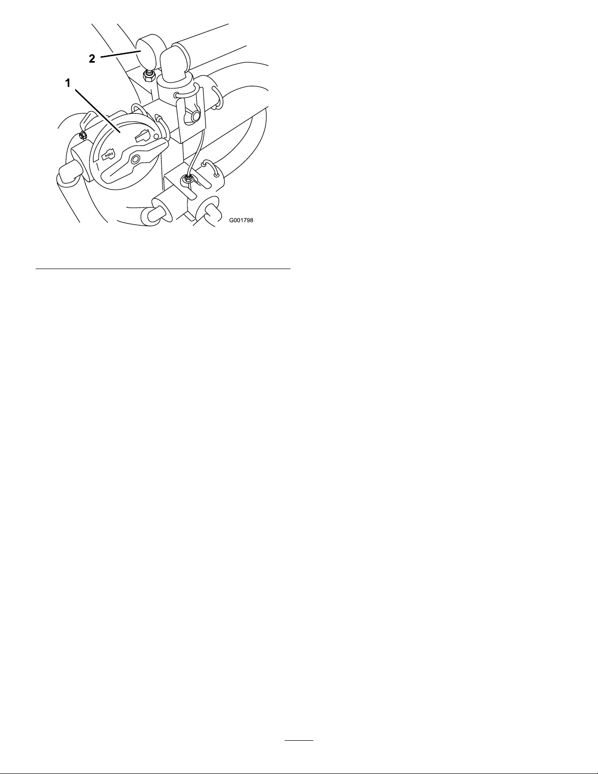
PressureGauge
Thepressuregaugeislocatedtotherightofthetank
Figure19).Thisgaugeshowsthepressureoftheuid
(
inthesysteminpsiandkPa.Usethegaugetoadjustthe
by-passvalveswheneveryouchangenozzles.
Anti-siphonFillReceptacle
Tothefrontofthetankcoverisahosereceptaclewitha
threadedtting,a90degreebarbedtting,andashort
hosewhichyoucandirecttowardthetankopening.This
receptacleallowsyoutoconnectawaterhosetoitand
llthetankwithwaterwithoutcontaminatingthehose
withthechemicalsinthetank.
Figure19
1.Agitationcontrolvalve2.Pressuregauge
Note:Foragitationtowork,thepumpmustbeon
andtheenginemustberunningaboveanidle.Ifyou
stopthesprayerandneedagitationon,placetherange
selectorintheNeutralposition,settheparkingbrake,
presstheacceleratorpedaltotheoor,turnthepump
OnandturntheneutralenginespeedlockOn.
Important:Donotlengthenthehosetoallow
contactwiththetankuids.
22
Page 23
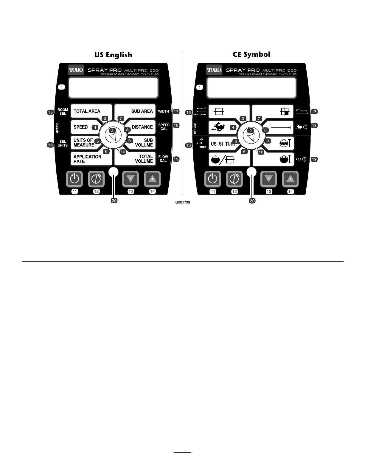
SprayPro™Monitor
TheSprayPromonitordisplaysandmonitorsvarious
systemperformancedatasuchasvehiclespeedand
applicationrates.Itdoesnotcontroltheapplicationrate.
ThemonitorhasanLCDscreenthatdisplaysthedata
youselect,aselectiondial,and4buttonsforcalibrating
themonitor(Figure20).
Figure20
1.LCDscreen
2.Selectiondial7.SubArea12.Calibrate,calibrationbutton
3.Totalarea8.Distance13.Decrease,calibration
4.Speed9.Subvolume
5.Unitsofmeasure
MonitorDisplaySelectionDial
UsethedialtosettheLCDscreendisplaytothe
following:
•Totalarea
Displaysthetotalacres(US),hectares(SI),orsqfeet
(TURF)thatyouhavecoveredsinceyoulastpressed
theResetcalibrationbuttonforthissetting.
•Speed
Displaysthegroundspeedinmilesperhour(ifthe
UnitsofMeasureissettoUSorTURF)orkilometers
perhour(iftheUnitsofMeasureissettoSI).
•UnitsofMeasure
Displaysthecurrentmeasurementunitselectionas
follows:
–US(UnitedStatesmeasuringsystem)
–SI(metricsystem)
–TURF(asUSbutthevolumesareinUSgallons
per1000sqftinsteadofUSgallonsperacre)
6.Applicationrate11.Reset,calibrationbutton
button
14.Increase,calibrationbutton19.Flowmetercalibration
10.Totalvolume15.Boomselection20.LED
•ApplicationRate
DisplaystheapplicationrateinUSgallonsperacre
(US),litersprehectare(SI),orUSgallonsper1000
sqft(TURF).
•SubArea
Displaysthetotalacres(US),hectares(SI),orsqfeet
(TURF)thatyouhavecoveredsinceyoulastpressed
theResetcalibrationbuttonforthissetting,without
affectingtheTotalAreadisplay.Ifyoupressthe
Resetcalibrationbutton,theSubVolumeresets.
•Distance
Displaysthedistanceyouhavetraveledinfeet(US
andTURF)ormeters(SI)sinceyoulastpressedthe
Resetcalibrationbuttonforthissetting.
•SubV olume
DisplaysthetotalvolumeinUSgallons(USand
TURF)orliters(SI)thatyouhaveappliedsinceyou
lastpressedtheResetcalibrationbuttonforthis
16.Selectunits
17.Width
18.Speedcalibration
23
Page 24
setting,withoutaffectingtheTotalVolumedisplay.
IfyoupresstheResetcalibrationbutton,theSub
Arearesets.
•TotalVolume
DisplaysthetotalvolumeinUSgallons(USand
TURF)orliters(SI)thatyouhaveappliedsinceyou
lastpressedtheResetcalibrationbuttonforthis
setting.
CalibrationButtons
Themonitorhasthefollowingbuttons:
•Reset
ResetstheTotalVolume,SubVolume,Distance,
TotalArea,andSubAreadisplaysettingsto0.
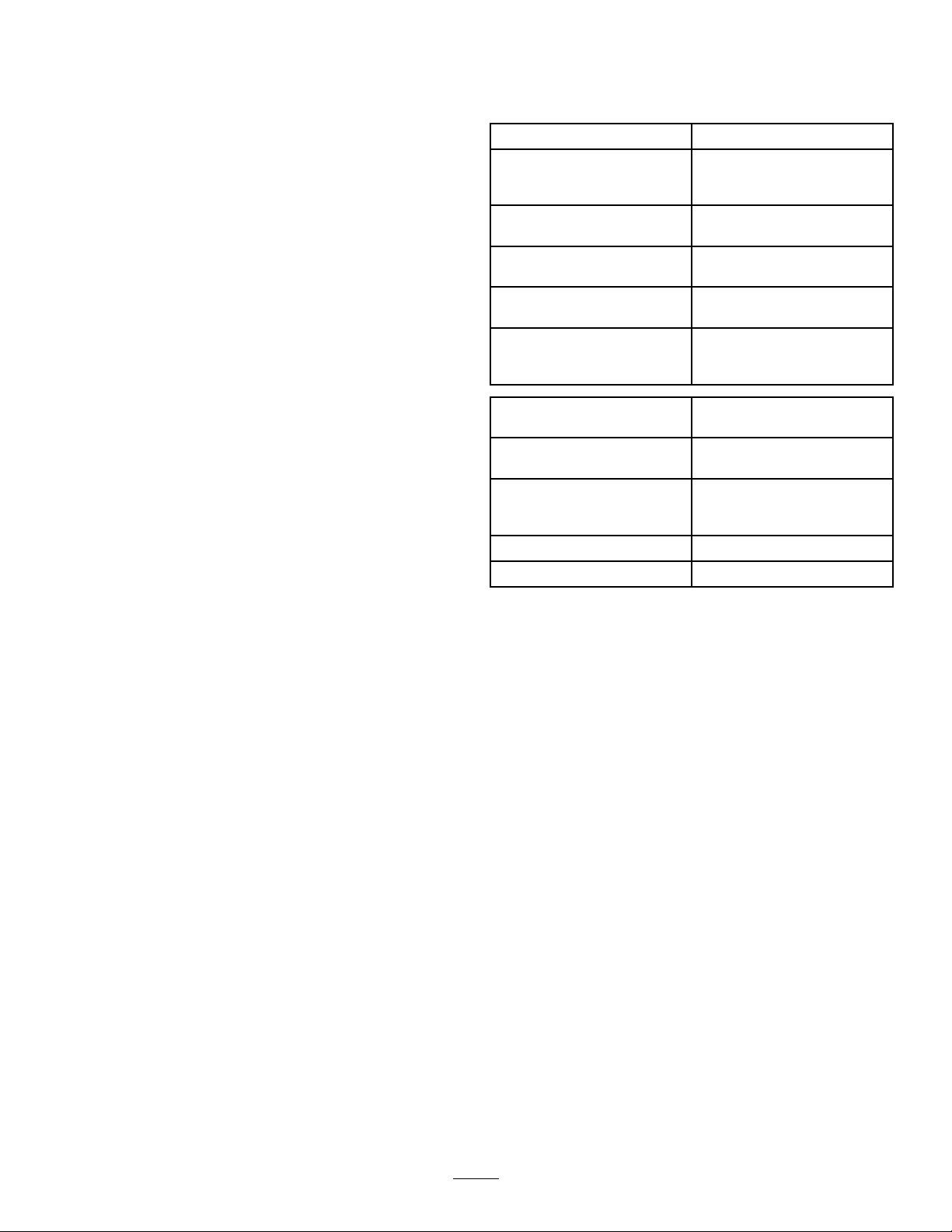
Specications
Note:Specicationsanddesignaresubjecttochange
withoutnotice.
Baseweight
Weightwithstandardspray
system,empty,without
operator
Weightwithstandardspray
system,full,withoutoperator
Maximumgrossvehicleweight
(GVW)(onlevelground)
Tankcapacity(includestheCE
5%overow)
Overallwidthwithstandard
spraysystemboomsstoredin
theXposition
2,061lb(934kg)
2,061lb(934kg)
3,661lb(1,660kg)
4,163lb(1,888kg)
175USgallons(662L)
69inches(175cm)
•Calibrate
Usedtoenterandexitthecalibrationmode.
•Decrease
Reducesvaluesdisplayedonthescreenduring
calibration.
•Increase
Increasesvaluesdisplayedonthescreenduring
calibration.
CalibrationSettings
•BoomWidth
•UnitsofMeasure
•Speed/Distance
•Flowmeter
Overalllengthwithstandard
spraysystem
Overallheightwithstandard
spraysystem
Overallheightwithstandard
spraysystemtothetopofthe
boomsstoredintheXposition
Groundclearance4.5inches(11.4cm)
Wheelbase
133inches(337cm)
52inches(132cm)
91inches(231cm)
62inches(157cm)
OptionalEquipment
TheToroCompanyhasoptionalequipmentand
accessoriesthatyoucanpurchaseseparatelyandinstall
onyoursprayer.ContactyourAuthorizedService
Dealerforacompletelistofoptionalequipmentthatis
currentlyavailableforyoursprayer.
24
Page 25
Operation
Note:Determinetheleftandrightsidesofthe
machinefromthenormaloperatingposition.
ChecktheTirePressure
Checkthetirepressureevery8hoursordailytoensure
properlevels.Fillthetiresto18psi(124kPa).Also,
checkthetiresforwearordamage.
ThinkSafetyFirst
Pleasecarefullyreadallofthesafetyinstructionsand
decalsinthesafetysection.Knowingthisinformation
couldhelpyouorbystandersavoidinjury.
BeforeDrivingtheSprayerfor
theFirstTime
ChecktheEngineOil
Theengineisshippedwithoilinthecrankcase;
however,thelevelofoilmustbecheckedbeforeyou
rststarttheengineandafteryouhaverunit.
1.Positionthemachineonalevelsurface.
2.Removethedipstickandwipeitwithacleanrag
Figure21).Insertthedipstickintothetubeand
(
makesureitisseatedfully.Removethedipstickand
checktheoillevel.
AddFuel
DANGER
Incertainconditions,gasolineisextremely
ammableandhighlyexplosive.Areorexplosion
fromgasolinecanburnyouandothersandcan
damageproperty.
•Fillthefueltankoutdoors,inanopenarea,
whentheengineiscold.Wipeupanygasoline
thatspills.
•Neverllthefueltankinsideanenclosedtrailer.
•Donotllthefueltankcompletelyfull.Add
gasolinetothefueltankuntilthelevelis1/4to
1/2inch(6to13mm)belowthebottomofthe
llerneck.Thisemptyspaceinthetankallows
gasolinetoexpand.
•Neversmokewhenhandlinggasoline,andstay
awayfromanopenameorwheregasoline
fumesmaybeignitedbyaspark.
•Storegasolineinanapprovedcontainerand
keepitoutofthereachofchildren.Neverbuy
morethana30-daysupplyofgasoline.
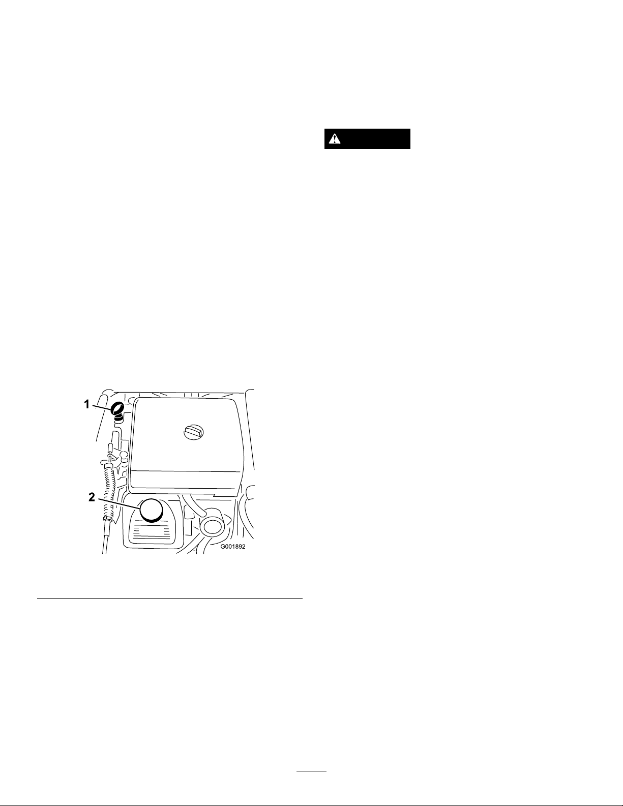
Figure21
1.Dipstick2.Fillercap
3.Iftheoillevelislow ,removethellercapfrom
thevalvecover(Figure21)andpouroilintothe
openinguntiltheoillevelisuptotheFullmark
onthedipstick;refertoServicingEngineOil,the
EngineMaintenancesection,fortheproperoiltype
andviscosity.Addtheoilslowlyandcheckthelevel
oftenduringthisprocess.Donotoverll.
4.Installthedipstickrmlyinplace.
•Donotoperatewithoutentireexhaustsystem
inplaceandinproperworkingcondition.
25
Page 26
DANGER
g0131 14
1
2
Incertainconditionsduringfueling,static
electricitycanbereleasedcausingasparkwhich
canignitethegasolinevapors.Areorexplosion
fromgasolinecanburnyouandothersandcan
damageproperty.
•Alwaysplacegasolinecontainersontheground
awayfromyourvehiclebeforelling.
•Donotllgasolinecontainersinsideavehicle
oronatruckortrailerbedbecauseinterior
carpetsorplastictruckbedlinersmayinsulate
thecontainerandslowthelossofanystatic
charge.
•Whenpractical,removegas-powered
equipmentfromthetruckortrailerandrefuel
theequipmentwithitswheelsontheground.
•Ifthisisnotpossible,thenrefuelsuch
equipmentonatruckortrailerfromaportable
container,ratherthanfromagasolinedispenser
nozzle.
•Ifagasolinedispensernozzlemustbeused,
keepthenozzleincontactwiththerimofthe
fueltankorcontaineropeningatalltimesuntil
fuelingiscomplete.
RecommendedGasoline
Usefresh,clean,unleadedregulargasolinesuitablefor
automotiveuse(87pumpoctaneminimum).Leaded
gasolinemaybeusedifunleadedregularisnotavailable.
Important:Neverusegasolinecontaining
methanol,gasolinecontainingmorethan10%
ethanol,gasolineadditives,orwhitegasbecause
enginefuelsystemdamagecouldresult.
FillingtheFuelTank
Thefueltankcapacityisapproximately5USgallons
(19L).
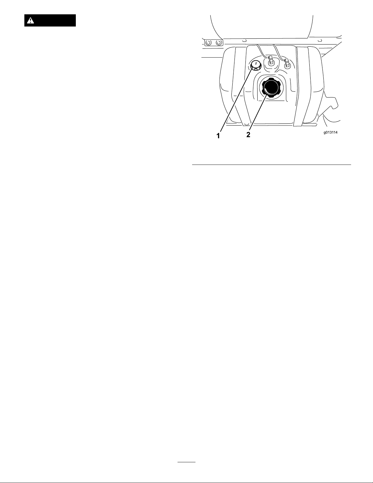
Note:Thefueltankcapcontainsagaugewhichshows
thefuellevel;checkitfrequently.
1.Shuttheengineoffandsettheparkingbrake.
2.Cleantheareaaroundthefueltankcap(
Figure22).
Figure22
1.Fuelgauge2.Fueltankcap
3.Removethefueltankcap.
4.Fillthetanktoaboutoneinchbelowthetopofthe
tank,(bottomofthellerneck).Thisspaceinthe
tankallowsgasolinetoexpand.Donotoverll.
5.Installthefueltankcapsecurely.
6.Wipeupanyfuelthatmayhavespilled.
Pre-StartingChecks
Checkthefollowingitemseachtimeyoubeginusing
thesprayerfortheday:
•Checkthetirepressure.
Note:Thesetiresaredifferentthancartires;they
requirelesspressuretominimizeturfcompaction
anddamage.
•Checkalluidlevelsandaddtheappropriate
amountofspecieduids,ifanyarefoundtobe
low .
•Checkthebrakepedaloperation.
•Checktoseethatthelightsareworking.
•Turnthesteeringwheeltotheleftandrightto
checksteeringresponse.
•Checkforoilleaks,looseparts,andanyother
noticeablemalfunctions.Makesuretheengineisoff
andallmovingpartshavestoppedbeforechecking
foroilleaks,looseparts,andothermalfunctions.
Ifanyoftheaboveitemsarenotcorrect,notifyyour
mechanicorcheckwithyoursupervisorbeforetaking
thesprayeroutfortheday.Yoursupervisormaywant
youtocheckotheritemsonadailybasis,soaskwhat
yourresponsibilitiesare.
26
Page 27

DrivingtheSprayer
StartingtheEngine
1.SitintheOperator’sseat,insertthekeyintothe
ignitionswitch,androtatethekeyclockwisetothe
Runposition.
2.Pressthebrakeandmovetherangeselectortothe
Neutralposition.
3.EnsurethatthepumpswitchisintheOffposition.
4.Iftheengineiscold,pullthechokeknobup.
Important:Donotusethechokeiftheengine
iswarm.
Figure23
1.Speedlimiterknob
2.Speedlimiterbutton4.Chokecontrol
3.Lockingring
5.TurnthekeytotheStartpositionuntiltheengine
starts.
Important:DonotholdthekeyintheStart
positionformorethan10seconds.Iftheengine
hasnotstartedafter10seconds,wait1minute
beforetryingagain.Donotattempttopushor
towthesprayertostarttheengine.
6.Oncetheenginestarts,pushthechokeknobdown
slowly.
Driving
1.Pressthebrakepedal.
2.Pushtheparkingbrakeleverforwardtoreleaseit.
3.Movetherangeselectorintothedesiredrange.
4.Presstheacceleratorpedaltodriveorpressthe
braketostop.
Note:Stoppingdistancemayvarydependingon
thesprayerloadandspeed.
3.Tonetunethesetting,turntheknobinoroutas
needed.
4.Onceyouhaveitset,youcanlockitatthatsetting
byturningthelockingringatthebaseofthespeed
limiterclockwiseuntilitstops(Figure23).To
releasethislock,turnthelockingringcounter
clockwiseuntilitisloose.
5.Toreleasethespeedlimiter,pressthebuttononthe
knobandloweritasfaraspossible.
StoppingtheEngine
1.Pressthebraketostopthesprayer.
2.Pulltheparkingbrakeleverupandbacktosetit.
3.MovetherangeselectoroutofgearintotheNeutral
position.
4.TurntheignitionkeytotheStopposition.
5.Removethekeyfromtheswitchtoprevent
accidentalstarting.
SettingtheSpeedLimiter
1.Pressdownontheacceleratorpedaltoobtainthe
desiredspeed.
2.Pressthebuttonontopofthespeedlimiter
knobandpulluponituntilyoufeelittouch
theacceleratorpedal,thenreleasethebutton
(Figure23).
NewSprayerBreak-In
Toprovideproperperformanceandlongsprayerlife,
followtheseguidelinesfortherst100operatinghours:
•Checktheuidandengineoillevelsregularly
andbealertforindicationsofoverheatinginany
componentofthesprayer.
•Afterstartingacoldengine,letitwarmupforabout
15secondsbeforeaccelerating.
•Avoidhardbrakingsituationsfortherstseveral
hoursofnewsprayerbreak-inoperation.New
brakeliningsmaynotbeatoptimumperformance
untilseveralhoursofusehascausedthebrakesto
becomeburnished(broken-in).
•Avoidracingtheengine.
27
Page 28

•Varythesprayerspeedduringoperation.Avoidfast
startsandquickstops.
•RefertotheMaintenancesectionforanyspecial
lowhourchecks.
AdjustingtheBoomstoLevel
Thefollowingprocedurecanbeusedtoadjustthe
hardstopsonthecenterboomtokeeptheleftandright
boomsatlevel.
1.Attheoperator’sposition,turntheignitionkeyto
Ontoenergizethesystem.
2.Movetheboomsintopositionsothattheyarelevel
withtheground.
3.Removethekeyandexittheoperator’sposition.
4.Atthehinge,adjustthepositionofthebumpersso
theboomcannotmovepastlevelwiththeground.
Takecaretomakesurethebumperislevel.
TheMulti-ProSprayerhasbeenspecicallydesignedto
havehighdurabilityinordertogiveitthelongsprayer
lifeyouneed.Differentmaterialshavebeenchosenfor
specicreasonsatdifferentlocationsonyoursprayerto
meetthisgoal.Unfortunatelythereisnosinglematerial
whichisperfectforallforeseeableapplications.
Somechemicalsaremoreaggressivethanothers
andeachchemicalinteractsdifferentlywithvarious
materials.Someconsistencies(e.g.wettablepowders,
charcoal)aremoreabrasiveandleadtohigherthan
normalwearrates.Ifachemicalisavailableina
formulationthatwouldprovideincreasedlifetothe
sprayer,usethisalternativeformulation.
Asalways,remembertocleanyoursprayerthoroughly
afterallapplications.Thiswilldothemosttoensure
yoursprayerhasalongandtroublefreelife.
FillingtheFreshWaterTank
5.Tightentheboltandnuttolockthebumpersinto
theadjustedposition.Torquethefastenersto
135-165ft-lbs(183-223N-m).
Note:Thebumpermayexperiencesomecompression
overtime.Iftheboomsdropbelowlevel,usethis
proceduretoreadjustthebumperpositionneeded.
OperatingtheSprayer
TooperatetheMulti-ProSprayerrstllthespraytank,
thenapplythesolutiontotheworkarea,andnally
cleanthetank.Itisimportantthatyoucompleteall
threeofthesestepsinsuccessiontoavoiddamagingthe
sprayer.Forexample,donotmixandaddchemicalsin
thespraytankatnightandthensprayinthemorning.
Thiswouldleadtoseparationofthechemicalsand
possibledamagetothesprayercomponents.
CAUTION
Chemicalsarehazardousandcancausepersonal
injury.
Alwaysllthefreshwatertankwithcleanwaterbefore
handlingormixinganychemicals.
Thefreshwatertankislocatedatthefront,leftside
ofthechemicaltank(Figure24).Itsuppliesasource
offreshwaterforyoutowashchemicalsoffofyour
skin,eyes,orothersurfacesinthecaseofaccidental
exposure.
•Readthedirectionsonthechemicallabels
beforehandlingthechemicalsandfollow
allmanufacturerrecommendationsand
precautions.
•Keepchemicalsawayfromyourskin.
Shouldcontactoccur,washtheaffectedarea
thoroughlywithsoapandcleanwater.
•Weargogglesandanyotherprotective
equipmentrecommendedbythechemical
manufacturer.
28
Page 29
Toopenthefreshwatertankspigot,turntheleveron
G001897
1
2
thespigot.
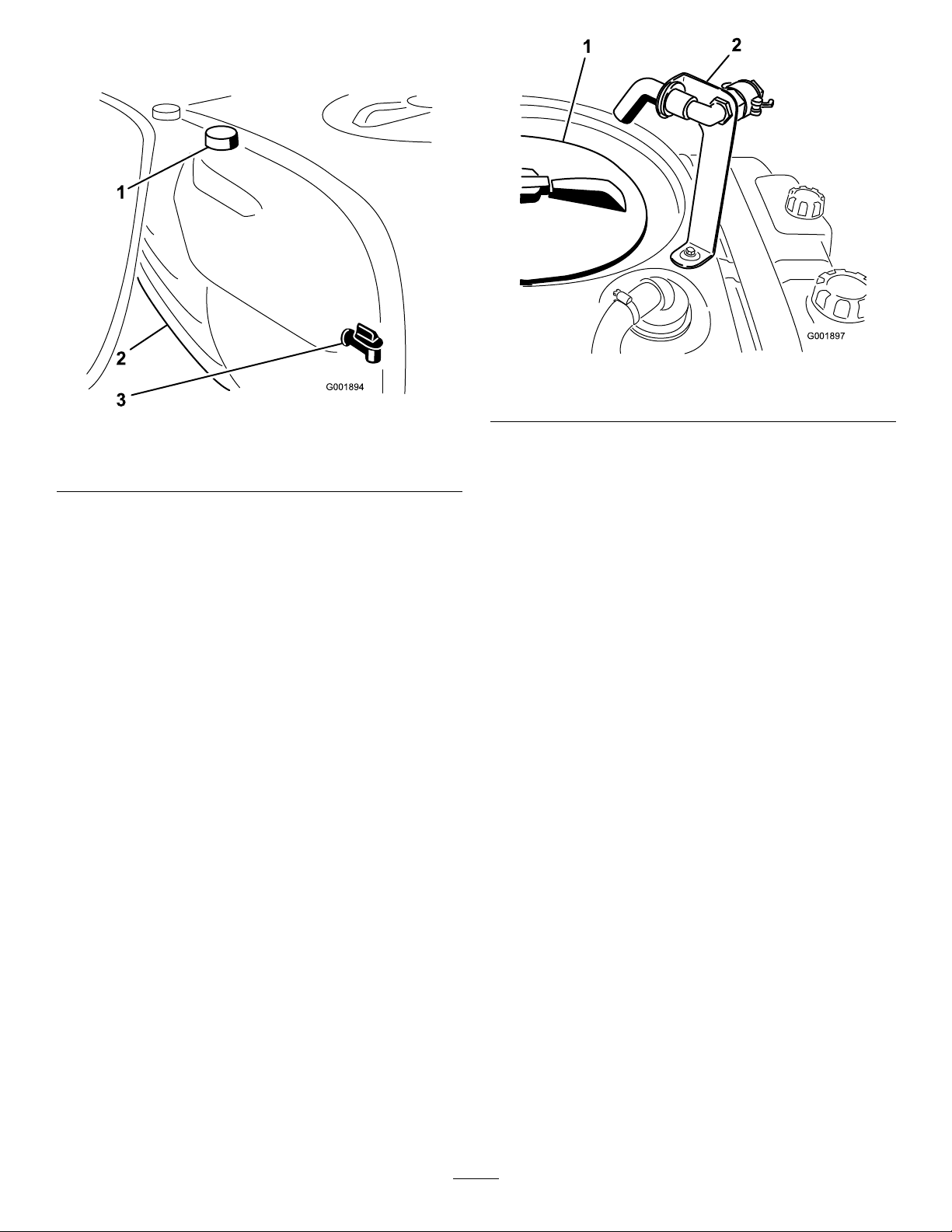
Figure24
1.Freshwatertank
2.Fillercap
3.Spigot
Figure25
1.Tankcover
2.Anti-siphonllreceptacle
5.Add3/4oftherequiredwatertothespraytank
usingtheanti-siphonllreceptacle.
FillingtheSprayTank
Important:Ensurethatthechemicalsyouwill
beusingarecompatibleforusewithViton(see
themanufacturer’slabel;itshouldindicateifit
isnotcompatible).Usingachemicalthatisnot
compatiblewithVitonwilldegradetheO-ringsin
thesprayer,causingleaks.
Important:Verifythattheproperapplicationrate
hasbeensetpriortollingthetankwithchemicals.
1.Stopthesprayeronalevelsurface,movetherange
selectortotheNeutralposition,stoptheengine,
andsettheparkingbrake.
2.Ensurethatthetankdrainvalveisclosed.
3.Determinetheamountofwaterneededtomixthe
amountofchemicalyouneedasprescribedbythe
chemicalmanufacturer.
4.Openthetankcoveronthespraytank.
Thetankcoverislocatedinthecenterofthetopof
thetank(
Figure25).Toopenit,turnthefronthalf
ofthecovercounterclockwiseandswingitopen.
Youcanremovethestrainerinsideforcleaning.T o
sealthetank,closethecoverandrotatethefront
halfclockwise.
Important:Alwaysusefreshcleanwaterin
thespraytank.Donotpourconcentrateinto
anemptytank.
6.SetthepumpswitchtotheOnposition.
7.Starttheengine,presstheacceleratorpedaltothe
oor,andsettheneutralenginespeedlocktothe
Onposition.
8.SetthemasterboomswitchtotheOffposition.
TheSprayPromonitorwilldisplay“HOLD”.
9.Turntheagitationcontrolvalvetothe9o’clock
positiontostartagitationinthetank.
10.Addtheproperamountofchemicalconcentrateto
thetank,asdirectedbythechemicalmanufacturer.
Important:Ifyouareusingawettablepowder,
mixthepowderwithasmallamountofwaterto
formaslurrybeforeaddingittothetank
11.Addtheremainingwatertothetank.
OperatingtheBooms
Theboomliftswitchesonthesprayercontrolpanel
allowsyoutomovetheboomsbetweentransport
positionandspraypositionwithoutleavingthe
Operator’sseat.Itisrecommendedtochangeboom
positionswhilethemachineisstationary.
Tochangetheboomposition:
1.Stopthesprayeronlevelground.
29
Page 30

2.Usetheboomliftswitchestolowerbooms.W ait
untiltheboomsreachthefull,extendedspray
position.
3.Whentheboomsneedtoberetracted,stopthe
sprayeronlevelground.
4.Usetheboomliftswitchestoraisethebooms.Raise
theboomsuntiltheyhavemovedcompletelyinto
boomtransportcradleformingthe“X”transport
positionandtheboomcylindersarefullyretracted.
Important:T opreventdamagetotheboom
actuatorcylinder,makesuretheactuatorsare
fullyretractedbeforetransport.
TheBoomTransportCradle
Thesprayerisequippedwithaboomtransportcradle
thathasauniquesafetyfeature.Intheeventof
accidentalboomcontactwithalowoverheadobject
whileinthetransportposition,theboom(s)canbe
pushedoutofthetransportcradles.Ifthisoccurs,the
boomswillcometorestinanearhorizontalposition
totherearofthevehicle.Whiletheboomswillnot
bedamagedduetothismovement,theyshouldbe
immediatelyputbackintothetransportcradle.
Important:Theboomscanbedamagedby
transportingtheminanypositionotherthanthe
“X”transportpositionusingtheboomtransport
cradle.
3.Settheindividualboomswitches,asneeded,tothe
Onpositions.
4.Drivetothelocationwhereyouwillbespraying.
5.TurntheSprayProselectiondialtotheApplication
Ratepositionandusetheapplicationrateswitchto
achievethedesiredrate.Todothis:
A.EnsurethepumpisOn.
B.Withthebrakepressed,selectthedesiredgear
rangethenbegindrivingatmaximumspeed.
C.Verifythemonitordisplaysthecorrect
applicationrate.Ifneeded,manipulatethe
applicationrateswitchuntilthemonitordisplays
thedesiredapplicationrate.
D.Returntothelocationwheresprayingisto
begin.
6.SetthemasterboomswitchtotheOnpositionto
beginspraying.
Note:Whenthetankisnearlyempty,theagitation
maycausefoaminginthetank.Inthiscase,
turntheagitationcontrolvalvetothe3o’clock
positiontoturnitoff.Alternatively,youcanusean
anti-foamingagentinthetank(ifcompatiblewith
thechemicalyouareusing).
7.Whennishedspraying,setthemasterboomswitch
totheOffpositiontoturnoffallbooms,thenset
thepumpswitchtotheOffposition.
Toputtheboomsbackintothetransportcradle,
lowertheboom(s)tothesprayposition,andthenraise
theboom(s)backintothetransportposition.Make
suretheboomcylindersarefullyretractedtoprevent
actuatorroddamage.
Spraying
Important:Inordertoensurethatyoursolution
remainswellmixed,usetheagitationfeature
wheneveryouhavesolutioninthetank.For
agitationtowork,thepumpmustbeonandthe
enginemustberunningaboveanidle.Ifyoustop
thevehicleandneedagitationon,placetherange
selectorintheNeutralposition,settheparking
brake,presstheacceleratorpedaltotheoor,turn
onthepump,andturntheneutralenginespeed
lockOn.
Note:Thisprocedureassumesthatthepumpison
fromtheFillingtheSprayTankprocedure.
1.Lowertheboomsintoposition.
SprayingTips
•Donotoverlapareasthatyouhavepreviously
sprayed.
•Watchforpluggednozzles.Replaceallwornor
damagednozzles.
•Usethemasterboomswitchtostopthesprayow
beforestoppingthesprayer.Oncestopped,place
therangeselectorinneutralandusetheneutral
enginespeedlocktoholdtheenginespeedupto
keeptheagitationrunning.
•Youwillobtainbetterresultsifthesprayeris
movingwhenyouturntheboomson.
•Watchforchangesintheapplicationratethatmay
indicatethatyourspeedhaschangedbeyondthe
rangeofthenozzlesorthereisaproblemwiththe
spraysystem.
CleaningtheSprayer
2.SetthemasterboomswitchtotheOffposition.
TheSprayPromonitorwilldisplay“HOLD”.
Important:Youmustalwaysemptyandcleanthe
sprayerimmediatelyaftereachuse.Failuretodo
30
Page 31
somaycausethechemicalstodryorthickeninthe
g0131 10
1
2
lines,cloggingthepumpandothercomponents.
Cleanthespraysystemaftereachsprayingsession.To
properlycleanthespraysystem:
•Usethreeseparaterinses.
•Useaminimumof50gallonsforeachrinse.
•Usethecleanersandneutralizersasrecommended
bythechemicalmanufacturers.
•Usepurecleanwater(nocleanersorneutralizers)
forthelastrinse.
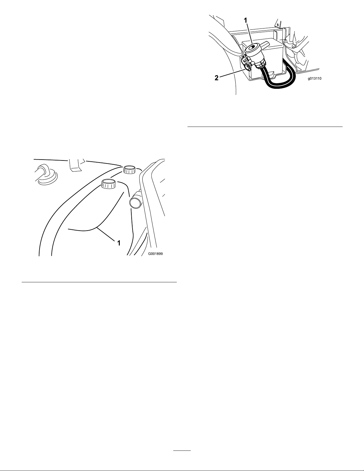
Therinsetankislocatedatthefront,rightsideofthe
chemicaltank(
Figure26).Ifyouinstalltheoptional
RinseKit,youcanllthistankwithfreshwaterand
automaticallyrinsethemaintank,boomsupplylines
andnozzles.
Figure26
1.Rinsetank(forusewiththeoptionalrinsekit,106-4842)
Figure27
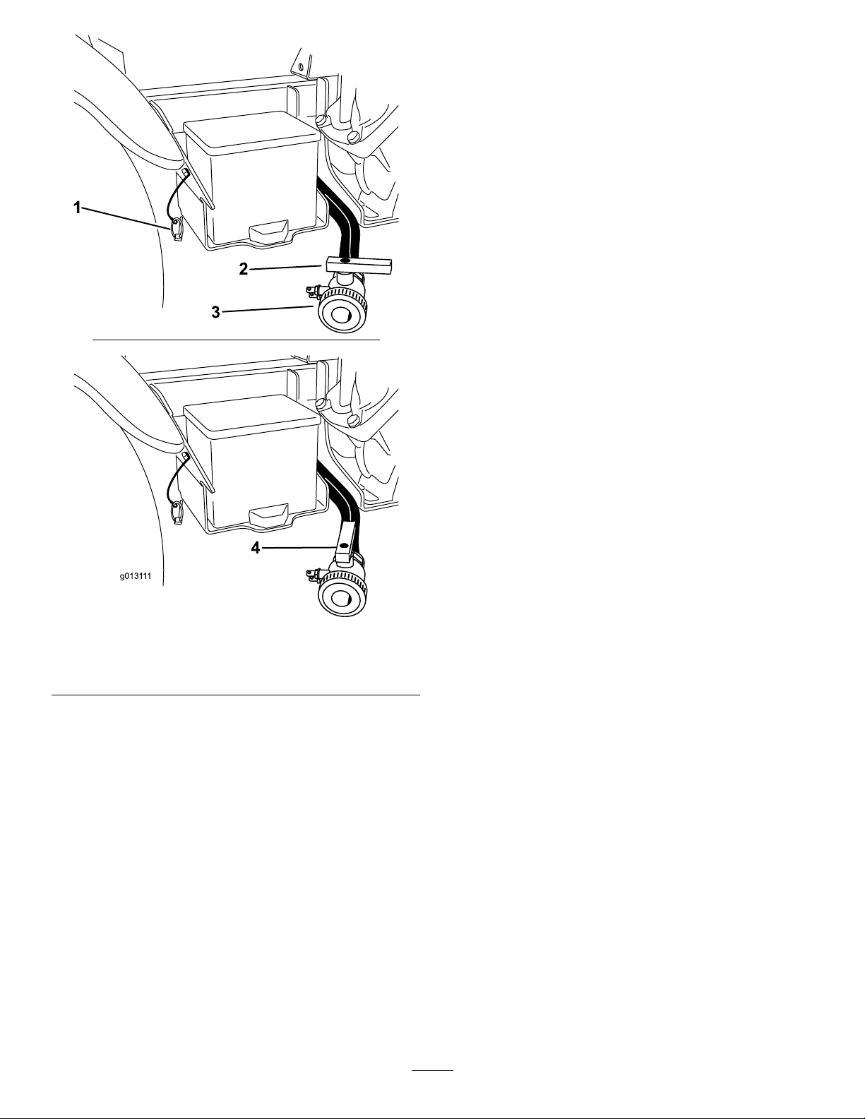
1.Tankdrain
2.Lynchpin
A.Removethelynchpinonthebracketsecuring
thedrainvalvetothemachineandletthevalve
restontheground.
B.Openthevalvetodrainanyunusedmaterial
fromthetankanddisposeofitaccordingto
localcodesandthematerialmanufacturer’s
instructions(
Figure28).Thisallowsanyresidual
materialinthelinetodrain.
1.Stopthesprayer,settheparkingbrake,placethe
rangeselectorintheNeutralposition,andturnoff
theengine.Thetankwilldraintoleftsideofthe
machine.
2.Locatethetankdrainvalveontherightsideofthe
machine(
Figure27).Thevalveisonthefender
bracketnexttothebattery.
31
Page 32
g0131 11
1
2
3
4
8.SetthepumpswitchtotheOnpositionandusethe
applicationrateswitchtoincreasethepressureto
ahighsetting.
9.Setthemasterboomswitchandboomcontrol
switchestotheOnpositionstobeginspraying.
10.Allowallofthewaterinthetanktosprayout
thoughthenozzles.
11.Checkthenozzlestoensurethattheyareall
sprayingcorrectly .
12.SetthemasterboomswitchtotheOffposition,
setthepumpswitchtotheOffposition,andstop
theengine.
13.Repeatsteps4through12atleast2moretimesto
ensurethatthespraysystemisfullycleaned.Onthe
lastcycle,runthelastfewgallonsofwaterthrough
thedrainvalvetoclearthedraintubing.
14.Cleanthestrainer;refertoCleaningtheSuction
StrainerintheCleaningsection.
Important:Ifyouusedwettablepowder
chemicals,cleanthestraineraftereachtank.
15.Usingagardenhose,sprayofftheoutsideofthe
sprayerwithcleanwater.
16.Removethenozzlesandcleanthembyhand.
Replacedamagedorwornnozzles.
Figure28
1.Lynchpin3.T ankdrain
2.Valveclosed4.V alveopen
3.Whenthetankhasdrainedcompletely,closethe
drainvalveandinstallthevalvetobracketwiththe
lynchpinremovedpreviously(Figure28).
4.Fillthetankwithatleast50USgallons(190L)of
cleanfreshwaterandclosethecover.
Note:Youcanuseacleaning/neutralizingagentin
thewaterasneeded.Onthenalrinse,useonly
clean,clearwater.
5.Starttheengine.
6.WiththerangeselectorintheNeutralposition,
presstheacceleratorpedaltotheoorandsetthe
neutralenginespeedlockswitchtotheOnposition.
7.EnsurethattheagitationcontrolvalveisintheOn
position.
32
Page 33
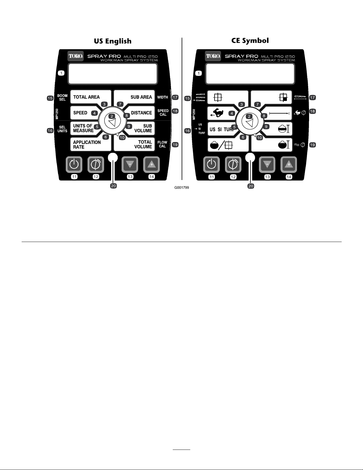
CalibratingtheSprayPro
Monitor
Figure29
1.LCDscreen
2.Selectiondial7.SubArea12.Calibrate,calibrationbutton
3.Totalarea8.Distance13.Decrease,calibrationbutton
4.Speed9.Subvolume
5.Unitsofmeasure
TheSprayPromonitorhasacalibrationmodethat
allowsyoutochangevarioussettingstocustomizethe
displayandcalibratethemonitortoyourneeds.You
cancalibrateorchangethefollowingsettings:
•BoomWidth
•UnitsofMeasure
6.Applicationrate11.Reset,calibrationbutton
14.Increase,calibrationbutton19.Flowmetercalibration
10.Totalvolume15.Boomselection20.LED
3.PressandholdtheCalibratebuttonuntilthe
monitordisplays“CALHOLD”andtheredlight
onthemonitorilluminates.
4.TurntheselectiondialtotheBoomSelect(orT otal
Area)position.
5.UsetheIncreaseorDecreasecalibrationbuttons
toselecttheboomforwhichyouwishtochange
•Speed
•Flowmeter
thewidth,where1istheleftboom,2isthecenter
boom,and3istherightboom.
6.TurntheselectiondialtotheWidth(orSubArea)
SettingtheBoomWidth
position.
7.UsetheIncreaseorDecreasecalibrationbuttonsto
Thedefaultsettingsfortheboomwidthsare80inches
(2.03m)fortherightandleftboomsand60(1.524m)
forthecenterboom.Thisisbasedon4nozzleson
therightandleftboomsand3onthecenterboomall
spaced20inches(50.8cm)apart.Ifyouchangethe
spacingofthenozzles,youshouldchangetheboom
widthtoreectyourchangesasfollows:
changetheboomwidthasneeded.
8.Repeatsteps4through7fortheotherboomsas
needed.
9.PresstheCalibratebuttonuntiltheredlightturns
off.Youcanalsoexitthecalibrationmodeby
drivingthesprayer.
16.Selectunits
17.Width
18.Speedcalibration
1.Stopthesprayerandsettheparkingbrake.
2.SetthemasterboomswitchtotheOffposition.
Themonitordisplays“HOLD”.
SettingtheUnitsofMeasure
ThedefaultsettingfortheunitsofmeasureisUS.You
canalsochangetheunitstoSI(metric)orTURF .
33
Page 34

1.Stopthesprayerandsettheparkingbrake.
2.SetthemasterboomswitchtotheOffposition.
Themonitordisplays“HOLD”.
3.PressandholdtheCalibratebuttonuntilthe
monitordisplays“CALHOLD”andtheredlight
onthemonitorilluminates.
4.TurntheselectiondialtotheSelectUnits(orUnits
ofMeasure)position.
5.UsetheIncreaseorDecreasecalibrationbuttonsto
selectdesiredunitsofmeasure.
6.PresstheCalibratebuttonuntiltheredlightturns
off.Youcanalsoexitcalibrationmodebydriving
thesprayer.
Thedisplaywillalternatebetweenthetotalvolume
reading(“HOLD”shown)andtheowcalibration
value(“CALHOLD”shown).
10.Whenthetotalvolumevalueisdisplayed,usethe
IncreaseorDecreasecalibrationbuttonstochange
ittotheamountofwateryouputinthetank.
11.Whenthedisplaybeginsalternatingagain,the
owcalibrationvaluewillhavechanged;writethis
numberdownandsaveit.Thisisthecalibration
valueforyoursprayer.
12.PresstheCalibratebuttonuntiltheredlightturns
off.Youcanalsoexitcalibrationmodebydriving
thesprayer.
CalibratingtheFlowmeter
Note:Performthiscalibrationprocedureeachtime
nozzlesarechangedtoensurethegreatestaccuracy.
TheSprayPromonitorcomesapproximatelycalibrated
fortheowmeter.Completethefollowingprocedure
tonetunetheowmetercalibration:
1.Settheparkingbrake.
2.Fillthesprayertankwithaknownquantityofwater,
atleast100USgallons(380L).
Note:Donotrelyonthemarksonthesideofthe
tankformeasuringthewaterforthisprocedure.
Theyareapproximatemeasurements,butnot
accurateenoughforthiscalibration.
3.SetthepumpswitchtotheOnpositiontostart
thepump.
4.Setallthreeboomswitchesandthemasterboom
switchtotheOnposition.Runtheboomsonly
untiltheairispurgedfromtheline,thenturnthem
offusingthemasterboomswitch.
5.TurntheselectiondialtotheTotalVolumeposition.
6.PressandholdtheResetcalibrationbuttonuntil
thedisplayreads“0”.
7.SetthemasterboomswitchtotheOnpositionand
runtheboomsuntilallthewaterisoutofthetank,
thenstopthemusingthemasterboomswitch.
8.Comparethevolumedisplayedonthemonitorto
thevolumeofwateryouputintothetank.
•Ifthevolumesarethesame,youdonotneedto
calibratethemonitoranyfurther.
•Ifthevaluesaredifferent,continuewiththerest
ofthisprocedure.
9.WiththeselectiondialsettotheTotalVolume
position,pressandholdtheCalibratebuttonuntil
themonitordisplays“CALHOLD”andthered
lightonthemonitorilluminates.
CalibratingtheSpeedSensor
TheSprayProcomesapproximatelycalibratedforthe
speedsensor.Completethefollowingproceduretone
tunethespeedsensorcalibration:
1.Checkandllalltires;refertoCheckingTire
PressureintheDriveSystemMaintenancesection.
2.Fillthefreshwatertank.
3.Fillthesprayertankhalf-fullofwater.
4.Selectastraight,attrackofgroundthatissimilar
toyourturfconditions.
Note:Usingaroadorotherpavedsurfacecould
causeaninaccuratereadingwhenyoulaterdrive
thesprayeronturf.
5.Measure500feet(150m),markingboththestart
andendpoints.
6.Positionthesprayeratthestartingpoint.
7.Setthepumpandthemasterboomswitchesto
theOffposition.Themonitorshoulddisplay
“HOLD”.
8.TurntheselectiondialtotheDistanceposition.
9.PressandholdtheResetcalibrationbuttonuntil
thedisplayreads“0”.
10.Pressthemasterboomswitchtostartthedistance
trackingwiththemonitor.Drivethemachinefrom
thestartpointyoumarkedtothe500feet(150m)
endpoint.
11.Stopattheendpoint,setthemasterboomswitch
totheOffpositiontostopthemonitor.
12.Lookatthedistancedisplayedonthemonitor.
•Ifitreads“500feet(150m)”,youdonotneed
tocalibratethemonitoranyfurther.
•Ifitdoesnotread“500feet(150m)”,continue
withtherestofthisprocedure.
13.Settheparkingbrake.
34
Page 35
14.WiththeselectiondialsettotheDistanceposition,
G012935
1
pressandholdtheCalibratebuttonuntilthe
monitordisplays“CALHOLD”andtheredlight
onthemonitorilluminates.
Thedisplaywillalternatebetweenthedistancevalue
(“HOLD”shown)andthespeedcalibrationvalue
(“CALHOLD”shown).
15.Whenthedistancevalueisdisplayed,usethe
IncreaseorDecreasecalibrationbuttonstochange
itto500feet(150m).
16.Whenthedisplaybeginsalternatingagain,the
speedcalibrationvaluewillhavechanged;writethis
numberdownandsaveit.Thisisthecalibration
valueforyoursprayer.
17.PresstheCalibratebuttonuntiltheredlightturns
off.Youcanalsoexitcalibrationmodebydriving
thesprayer.
ResettinganOFLCondition
Ifthemonitorreads“OFL”,itindicatesthatyouhave
exceededthemonitorscreendimensions.Pressand
holdtheResetcalibrationbuttontosetthedisplayto0.
forthenozzlesyouinstalledonthebooms(typically
40psi/2.75bar).
10.Recordthereadingonthepressuregauge.
11.Turnoffoneoftheboomsusingtheappropriate
boomswitch.
12.Adjusttheboombypassvalve(Figure30)onthe
boomcontrolvalvefortheboomyouturnedoff
untilthepressurereadingonthegaugeisthesame
asitwasinstep
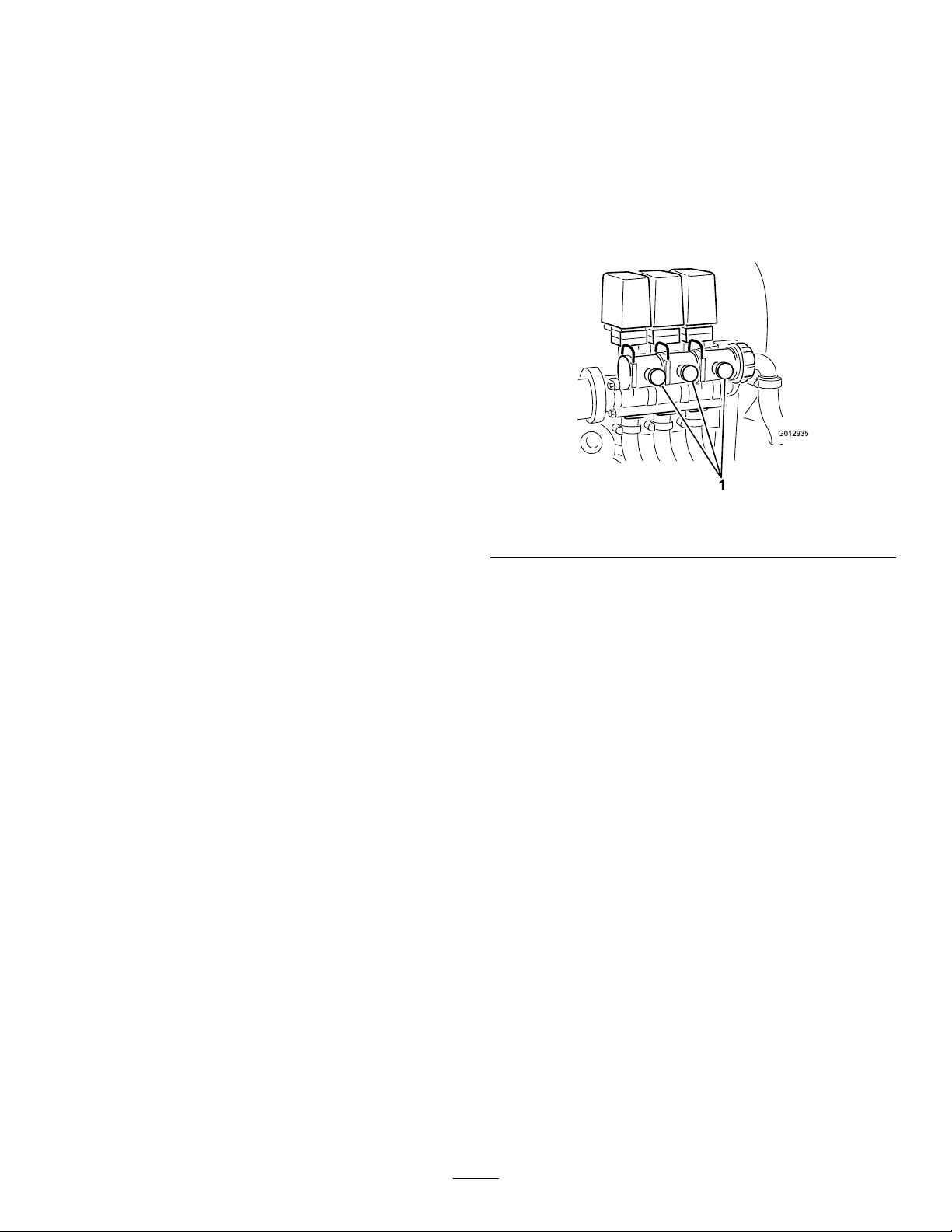
1.Boombypassvalves
9.
Figure30
CalibratingtheBoomBypass
Valves
Beforeusingthesprayerforthersttimeorifthe
nozzlesarechanged,adjusttheboombypassvalvesso
thatthepressureandapplicationrateremainsthesame
forallboomswhenyouturnoneormoreboomsoff.
Note:Theboombypassvalvesmustbecalibrated
eachtimethenozzlesarechanged.
Selectanopenatareatoperformthisprocedure.
1.Fillthespraytankwithcleanwater.
2.Puttheextensionboomsdown,ifinstalled.
3.Settheparkingbrakeandstarttheengine.
4.SetthedialontheSprayPromonitortoApplication
Rate.
5.PlacetherangeselectorintheNeutralposition.
6.Presstheacceleratortotheoorandsettheneutral
enginespeedlockswitchtotheOnposition.
7.SetthepumpswitchtotheOnpositiontostart
thepump.
13.Turntheboomonandofftoverifythepressure
doesnotchange.
14.Repeatsteps11through13fortheotherbooms.
15.Drivethesprayeratthedesiredspeedwhilespraying
andturneachboomoffindividually.Thepressure
onthegaugeshouldnotchange.
Pump
Thepumpislocatednearthefrontofthetankonthe
rightside(
Figure31).
8.Setallthreeboomswitchesandthemasterboom
switchtotheOnposition.
9.Usetheapplicationrateswitchtoadjustthepressure
asreadonthepressuregaugeuntilitisintherange
35
Page 36
G010597
1.Tiedownpoints
Figure33
Figure31
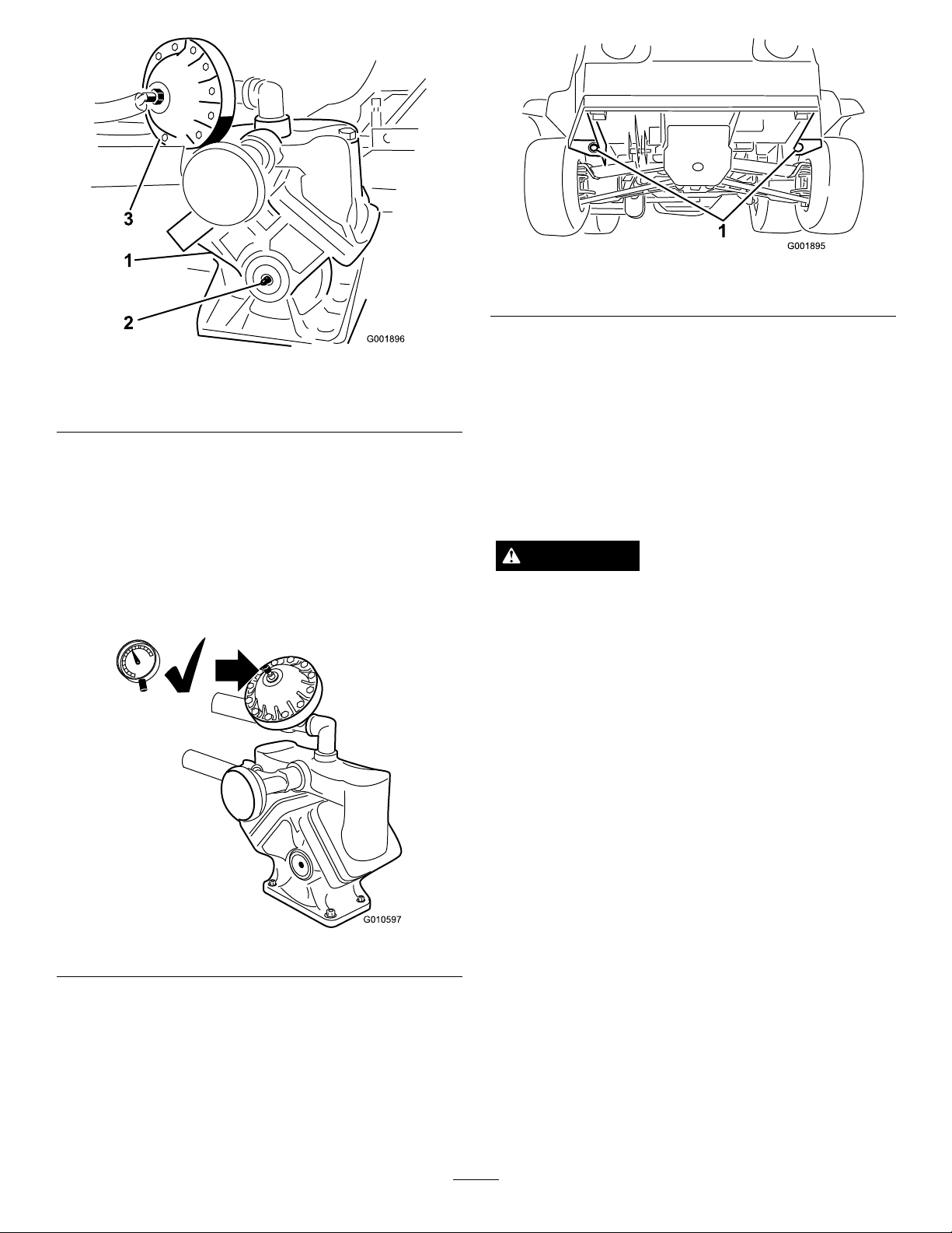
1.Pump3.Pressuredampener
2.Greasetting
AdjustingtheAirPressurein
Dampener
Theairpressureinthedampeneronthepumpissetat
15psi(1bar)bythemanufacturer.Therecommended
pressureinthedampeneris1/3ofthespraying
pressure.Ifusingaspraypressuregreaterthan45psi
(3.1bar)adjustthedampeneraccordingly.
Thereartie-downpointsaretwosteelloopsunderthe
backoftheframejustinfrontoftheadjustableboom
frame.
TowingtheSprayer
Incaseofanemergency,thesprayercanbetowedfor
ashortdistance.However,wedonotrecommendthis
asastandardprocedure.
WARNING
Towingatexcessivespeedscouldcausealossof
steeringcontrol,resultinginpersonalinjury .
Nevertowthesprayerfasterthan5mph(8kph).
Towingthesprayerisatwopersonjob.Ifthemachine
mustbemovedaconsiderabledistance,transportiton
atruckortrailer;refertoTransportingtheSprayer.
1.Afxatowlinetotheframe.
2.PuttherangeselectorintheNeutralpositionand
releasetheparkingbrake.
Figure32
TransportingtheSprayer
Formovingthesprayerlongdistances,useatrailer.
Securethesprayertothetrailer.Figure33illustrates
thefronttie-downpoints.
3.Towthesprayeratlessthan5mph(8kph).
36
Page 37

Maintenance
Note:Determinetheleftandrightsidesofthemachinefromthenormaloperatingposition.
RecommendedMaintenanceSchedule(s)
MaintenanceService
Interval
Aftertherst8hours
Aftertherst50hours
Beforeeachuseordaily
Every25hours
Every50hours
Every100hours
MaintenanceProcedure
•T orquethewheellugnuts.
•Checkthedrivebelt.
•Checkthesteeringpumpbelttension.
•Replacethehydrauliclter.
•Changetheengineoil.
•Checkpumpdampenerpressure.
•Checktheenginerotatingscreen.
•Checktheengineoil.
•Checkthetirepressure.
•Checkpumpdampenerpressure.
•Cleanthesuctionstrainer.(moreoftenwhenusingwetablepowders)
•Cleanandoilthefoamaircleaner(moreoftenindusty,dirtyconditions).
•Lubricatethepump.
•Checkthebatterycableconnections.
•Checkthebatteryelectrolytelevel.
•Lubricateallgreasettings.
•Lubricatetheboomhinges.
•Cleantheenginerotatingscreen(moreoftenindusty,dirtyconditions).
•Replacethepaperaircleanerelement(moreoftenindusty,dirtyconditions).
•Changetheengineoil,includingsyntheticoil(moreoftenwhenoperatingunder
heavyloadorinhightemperature).
•Replacetheengineoillter.
•Replacethefuellter.
•T orquethewheellugnuts.
•Inspecttheconditionandwearofthetires.
•Checkfrontwheeltoe-in.
•Inspectthebrakes.
•Checkthesteeringpumpbelttension.
Every200hours
Every400hours
•Changethesparkplugs.
•Checktheparkingbrake.
•Checkthedrivebelt.
•Checkthetransaxle/hydraulicuid.
•Inspectallhosesandconnectionsfordamageandproperattachment.
•Cleantheowmeter.(Moreoftenwhenusingwettablepowders)
•Greasetheactuatorrodbearings.
•Completeallyearlymaintenanceprocedurespeciedintheengineoperator’s
manual.
•Inspectthefuellines.
•Drainandcleanthefueltank.
•Inspectthepumpdiaphragmandreplaceifnecessary.(seeanAuthorizedToro
ServiceDistributor)
•Inspectthepressuredampenerbladderandreplaceifnecessary.(seeanAuthorized
ToroServiceDistributor)
•Inspectthepumpcheckvalvesandreplaceifnecessary.(seeanAuthorizedToro
ServiceDistributor)
•Changethepumpdrivegearboxuid.
•Checkboomactuatorhydraulicoilforairbubbles.
37
Page 38
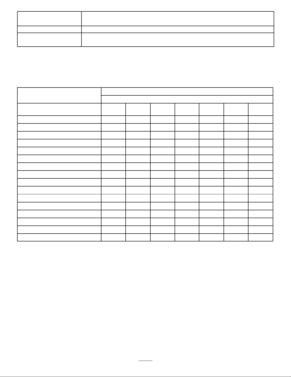
MaintenanceService
Interval
MaintenanceProcedure
•Inspectthecenterboomnylonpivotbushings.
Every800hours
•Changethetransaxle/hydraulicuidandcleanstrainer.
•Replacethehydrauliclter.
Important:Refertoyourengine
DailyMaintenanceChecklist
Duplicatethispageforroutineuse.
Checkthebrakeandparkingbrake
operation.
Checkthegearshift/neutraloperation.
Checkthefuellevel.
Checktheengineoillevel.
Checkthetransaxleoillevel.
Inspecttheairlter.
Inspecttheenginecoolingns.
Checkanyunusualenginenoises.
Checkanyunusualoperatingnoises.
Checkthetirepressure.
Checkforuidleaks.
Checktheinstrumentoperation.
Checktheacceleratoroperation.
Cleanthesuctionstrainer.
Checktoe-in.
Lubricateallgreasettings.
Touchupanddamagedpaint.
1
Operator’ s Man ual
Fortheweekof: MaintenanceCheckItem
Mon.Tues.Wed.Thurs.Fri.
foradditionalmaintenanceprocedures.
Sat.Sun.
1
Immediatelyaftereverywashing,regardlessoftheintervallisted
38
Page 39
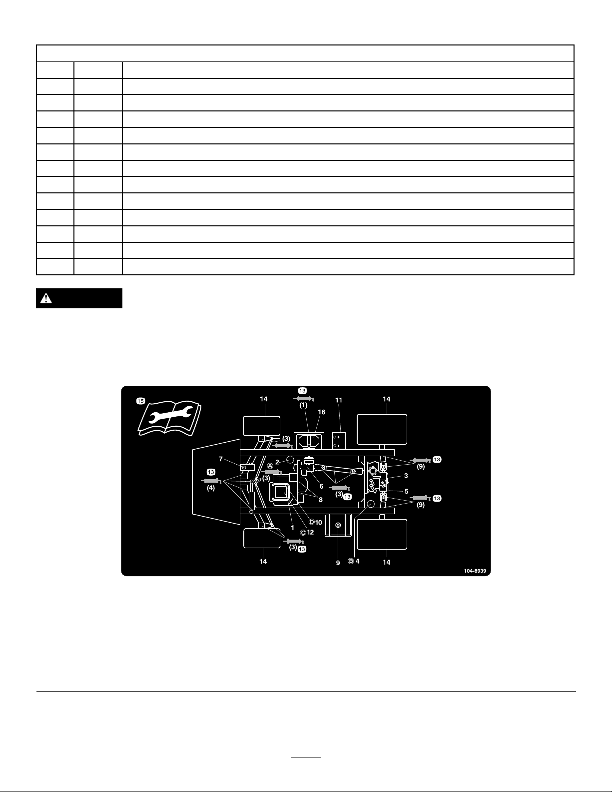
NotationforAreasofConcern
Inspectionperformedby:
ItemDate
1
2
3
4
5
6
7
8
9
10
11
12
CAUTION
Ifyouleavethekeyintheignitionswitch,someonecouldaccidentlystarttheengineandseriouslyinjure
youorotherbystanders.
Information
Removethekeyfromtheignitionanddisconnectthewire(s)fromthesparkplug(s)beforeyoudoany
maintenance.Setthewire(s)asidesothatitdoesnotaccidentallycontactthesparkplug(s).
Figure34
Servicelocations
1.Engineoillevel(dipstick)
2.Engineoillter6.Gearboxuidlevel10.Fuellter
3.Transaxle/hydraulicuid
level(dipstick)
4.Transaxlehydrauliclter
5.Hydraulicstrainer9.Fuel,unleadedonly
7.Brakeuid
8.Belts,steeringanddrive12.Aircleaner16.Pump
11.Battery15.Readtheinstructions
13.Grease
14.Tirepressure
beforeservicingor
performingmaintenance.
39
Page 40
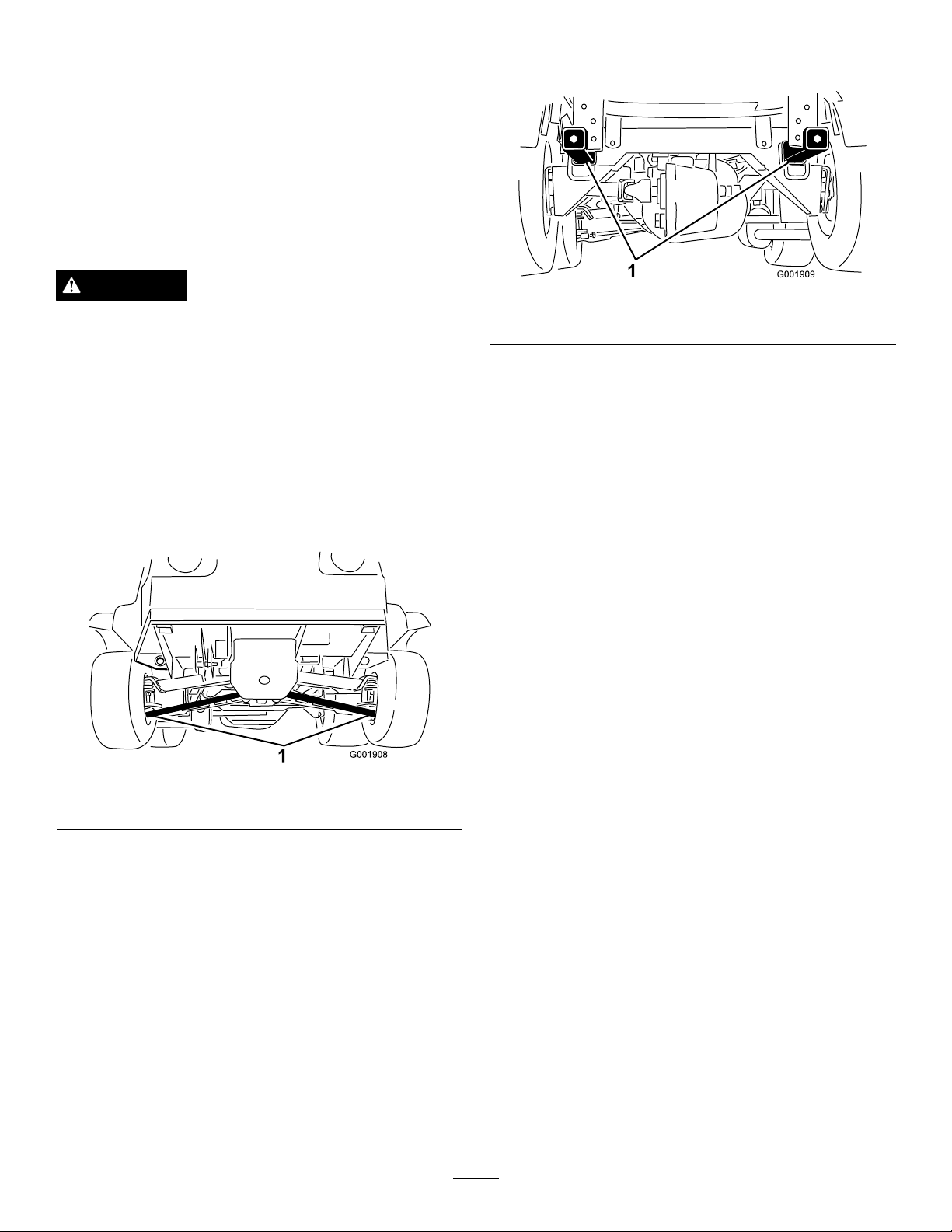
Premaintenance
Procedures
JackingtheSprayer
Whenevertheengineisrunforroutinemaintenance
and/orenginediagnostics,therearwheelsofthesprayer
shouldbe1inch(25mm)offofthegroundwiththe
rearaxlesupportedonjackstands.
Thejackingpointattherearofthesprayerisontherear
framesupport,betweentheanglewelds(Figure36).
DANGER
Asprayeronajackmaybeunstableandslipoffof
thejack,injuringanyonebeneathit.
•Donotstarttheenginewhilethesprayerisona
jack.
•Alwaysremovethekeyfromtheignitionbefore
gettingoffofthesprayer.
•Blockthetireswhenthesprayerisonajack.
Thejackingpointatthefrontofthesprayerisunderthe
A-arms(Figure35)
Figure36
1.Rearjackingpoints
1.Frontjackingpoints
Figure35
40
Page 41
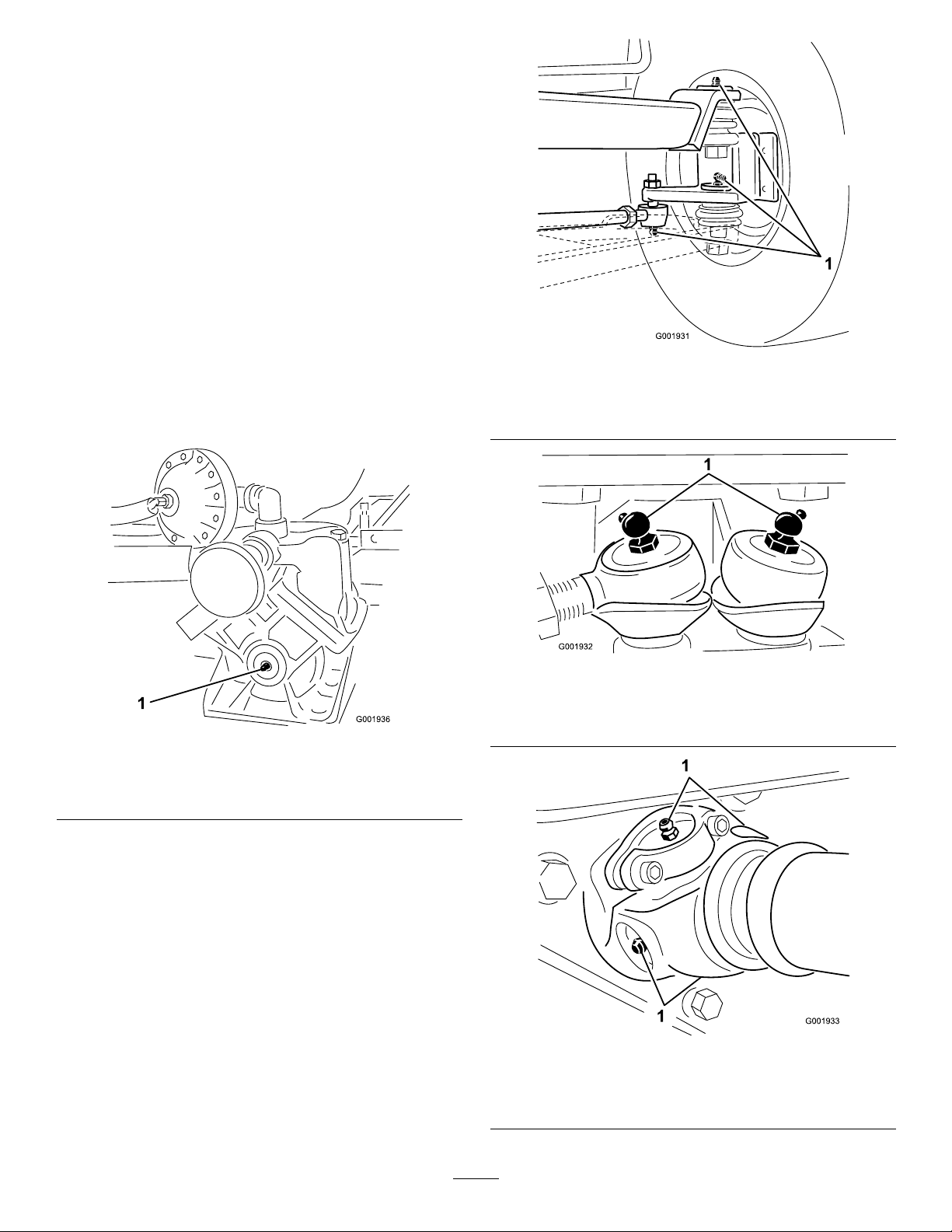
Lubrication
GreasingtheSprayer
ServiceInterval:Every50hours—Lubricatethepump.
Every100hours/Yearly(whichever
comesrst)—Lubricateallgrease
ttings.
GreaseType:No.2GeneralPurposeLithiumBase
Grease
1.Wipethegreasettingcleansothatforeignmatter
cannotbeforcedintothebearingorbushing.
2.Pumpgreaseintothebearingorbushing.
3.Wipeoffexcessgrease.
Thegreasettingspositionsareillustratedbythe
following:
1.Greasepoint
Figure38throughFigure43.
Figure37
Pump(Donotovergrease)
Figure38
Atthewheels,threeoneachside
1.Greasepoint
Figure39
Steeringrods
1.Greasepoint
41
Figure40
Pumpdrive,four,oneeachside
1.Greasepoint
Page 42
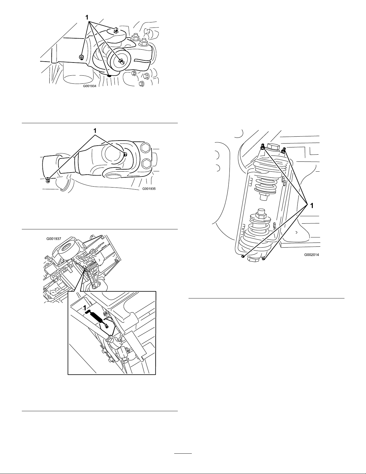
Figure41
Driveaxelatengine,ve,oneeachsideandslipjoint
GreasingtheBoomHinges
ServiceInterval:Every100hours
Important:Iftheboomhingeiswashedwith
water,allwateranddebrismustbeclearedfromthe
hingeassemblyandfreshgreasemustbeapplied.
GreaseType:No.2general-purposelithiumbase
grease.
1.Wipethegreasettingscleansothatforeignmatter
cannotbeforcedintothebearingorbushing.
1.Greasepoint
1.Greasepoint
2.Pumpgreaseintothebearingorbushingateach
tting
Figure42
Driveaxelattransmission
Figure44.
Figure44
Rightboom
1.Greasepoint
Figure43
Steeringpivotabovesteeringrods
1.Greasetting
3.Wipeoffexcessgrease.
4.Repeattheprocedureforeachboompivot.
GreasingtheActuatorRod
Bearings
ServiceInterval:Every400hours/Yearly(whichever
comesrst)
GreaseType:No.2general-purposelithiumbase
grease.
1.Extendtheboomstothesprayposition.
2.Removethecotterpinfromthepivotpin(Figure45).
42
Page 43
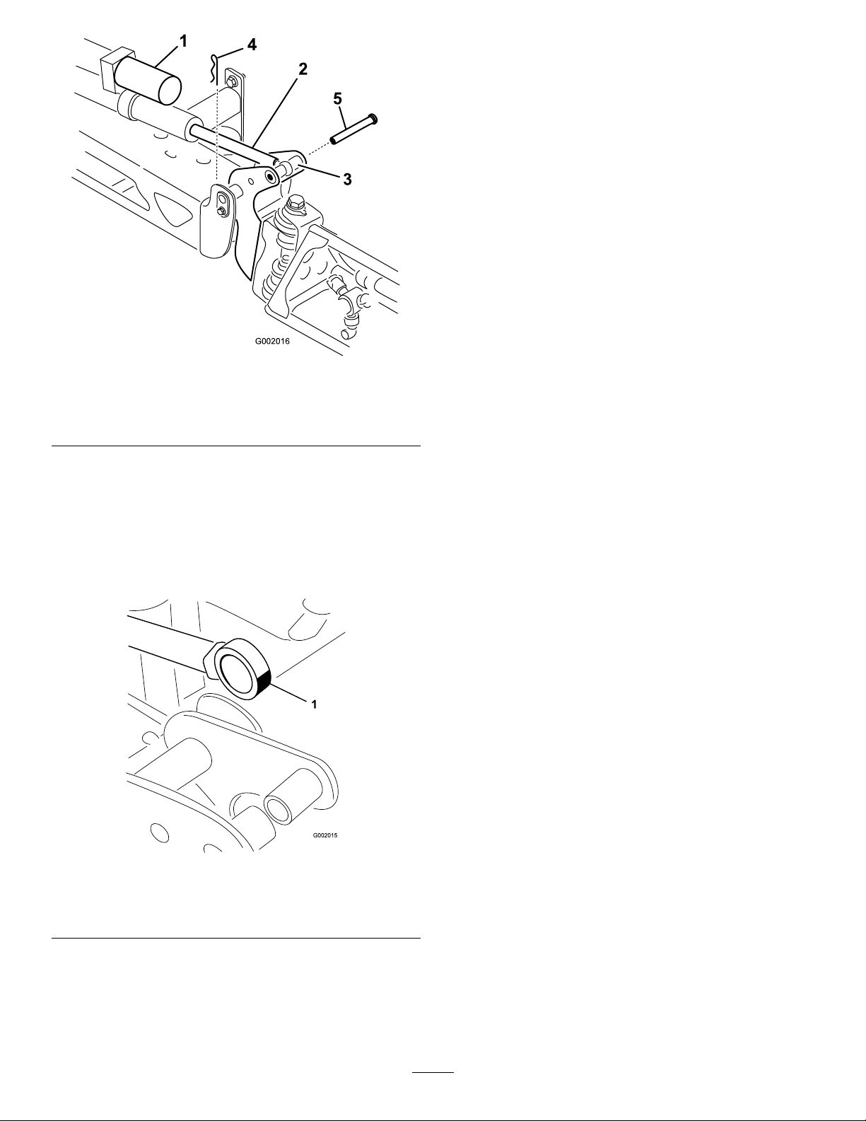
G002016
1
4
2
3
5
Figure45
1.Actuator
2.Actuatorrod5.Pin
3.Boompivotpinhousing
7.Withthepininplace,releasetheboomandsecure
thepinwiththecotterremovedpreviously.
8.Repeattheprocedureforeachactuatorrodbearing.
4.Cotter
3.Liftupontheboomandremovethepin(Figure45).
Slowlylowertheboomtotheground.
4.Inspectthepinforanydamage,replaceifnecessary.
5.Manipulatetheactuatorrodbearingendandapply
greaseintothebearing(
Figure46).Wipeoffexcess
grease.
Figure46
Rightboom
1.Greasebearing
6.Raisetheboomtoalignthepivotwiththeactuator
rod.Whileholdingtheboom,insertthepinthrough
bothboompivotandactuatorrod(Figure45).
43
Page 44
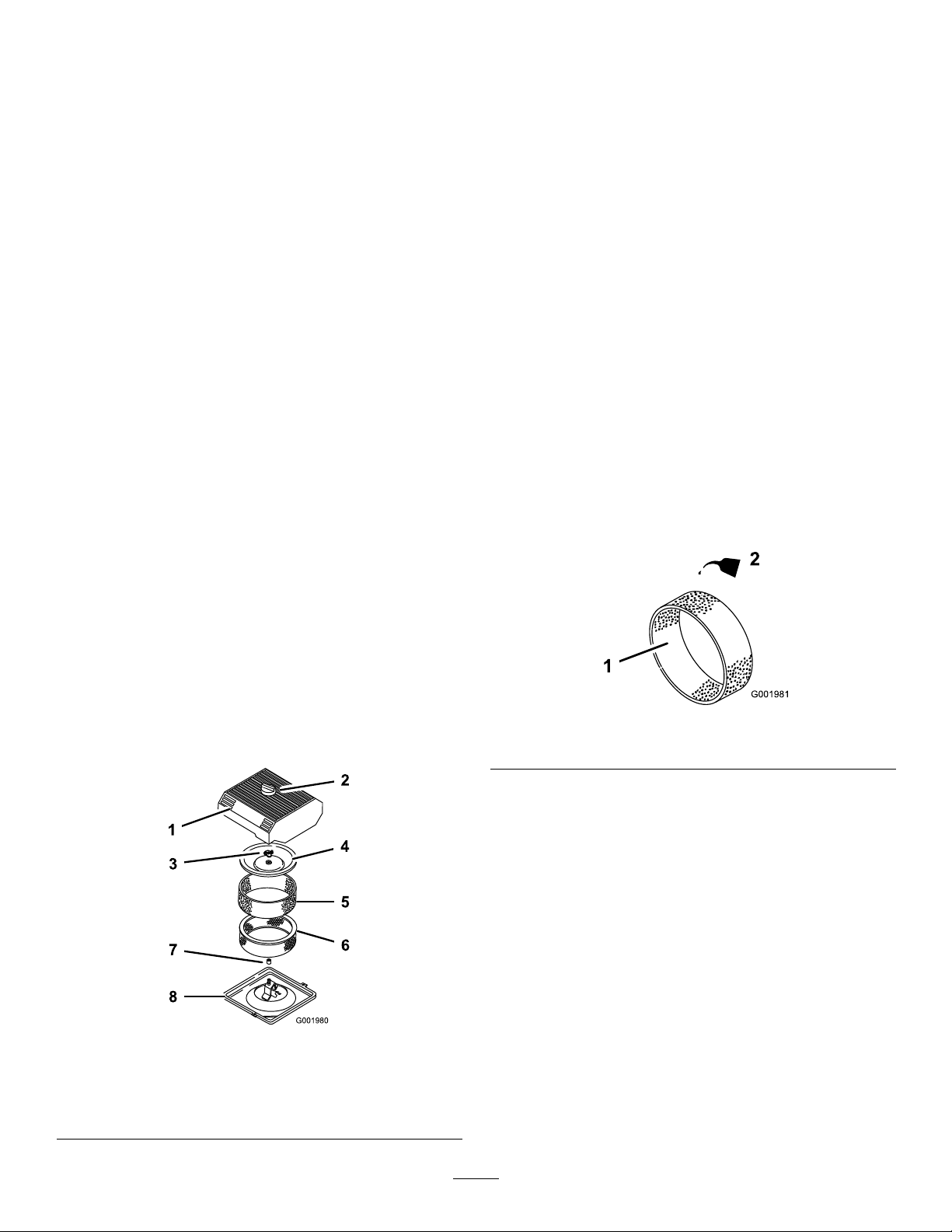
EngineMaintenance
4.Loosentheknobontheaircleanercoverandremove
thecover(Figure47).
CheckingtheAirIntakeScreen
ServiceInterval:Beforeeachuseordaily—Checkthe
enginerotatingscreen.
Every100hours—Cleantheengine
rotatingscreen(moreoftenindusty,
dirtyconditions).
Checkandcleanasnecessarytheairintakescreenonthe
frontoftheenginebeforeeachuseordaily.
ServicingtheAirCleaner
FoamElement:Cleanandoilafterevery25operating
hours,oryearly,whicheveroccursrst.
PaperElement:Replaceafterevery100operating
hoursoryearly ,whicheveroccursrst.
Note:Servicetheaircleanermorefrequently(every
fewhours)ifoperatingconditionsareextremelydusty
ordirty.
5.Carefullyslidethefoamelementoffthepaper
element(
Figure47).
6.Unscrewthecovernutandremovethecoverand
paperelement(Figure47).
CleaningtheFoamElement
ServiceInterval:Every25hours/Yearly(whichever
comesrst)—Cleanandoilthefoam
aircleaner(moreoftenindusty,dirty
conditions).
1.Washthefoamelementinliquidsoapandwarm
water.
2.Whentheelementisclean,rinseitthoroughly.
3.Drytheelementbysqueezingitinacleancloth.
4.Putoneortwoouncesofoilontheelement
Figure48).
(
Important:Replacethefoamelementifitis
tornorworn.
RemovingtheFoamandPaper
Elements
1.Settheparkingbrake,stopthepump,stopthe
engine,andremovetheignitionkey .
2.Releasethelatchonthebackoftheseatandliftthe
seatforward.
3.Cleanaroundtheaircleanertopreventdirt
fromgettingintotheengineandcausingdamage
(Figure47).
Figure47
1.Aircleanercover5.Foamelement
2.Knob6.Paperelement
3.Covernut
4.Cover
7.Rubberseal
8.Aircleanerbase
Figure48
1.Foamelement
2.Oil
5.Squeezetheelementtodistributetheoil.
CheckingthePaperElement
ServiceInterval:Every100hours/Yearly(whichever
comesrst)—Replacethepaperair
cleanerelement(moreoftenindusty,
dirtyconditions).
Inspectthepaperelementfortears,anoilylm,damage
totherubberseal,excessivedirt,orotherdamage
(Figure49).Ifanyoftheseconditionsexit,replacethe
lter.
Important:Donotcleanthepaperelementwith
pressurizedairorliquids,suchassolvent,gas,or
kerosene.
44
Page 45
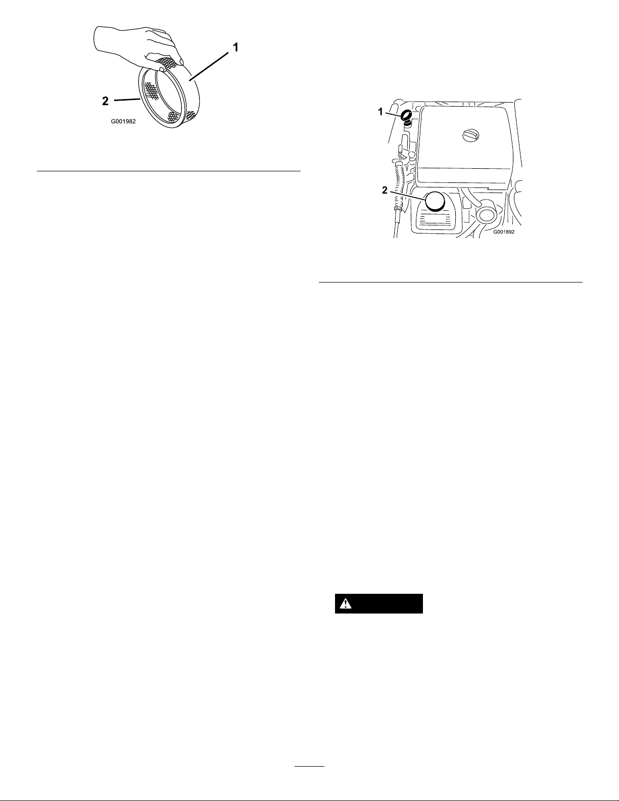
Figure49
1.Paperelement2.Rubberseal
Important:Topreventenginedamage,always
operatetheenginewiththecompletefoamand
paperaircleanerassemblyinstalled.
1.Positionthemachineonalevelsurface.
2.Removethedipstickandwipeitwithacleanrag
(
Figure50).Insertthedipstickintothetubeand
makesureitisseatedfully.Removethedipstickand
checktheoillevel.
InstallingtheFoamandPaperElements
1.Carefullyslidethefoamelementontothepaperair
cleanerelement(Figure47).
2.Slidetheaircleanerassemblyandcoverontothe
longrod.
3.Installthecovernutnger-tightagainstthecover
(
Figure47).
Note:Ensurethattherubbersealisatagainstthe
aircleanerbaseandcover.
4.Installtheaircleanercoverandknob(Figure47).
5.Closeandlatchtheseat.
ServicingtheEngineOil
CrankcaseCapacityis2.1qt(2.0l)withthelter.
Usehigh-qualityengineoilthatmeetsthefollowing
specications:
•APIclassicationLevelrequired:SJ,JK,SL,or
higher.
•Preferredoil:SAE10W30(above0degreesF)
•Alternateoil:SAE5W30(below32degreesF)
ToroPremiumEngineOilisavailablefromyour
distributorineither10W30or5W30viscosity.Seethe
PartsCatalogforpartnumbers.
ChecktheEngineOil
ServiceInterval:Beforeeachuseordaily
Every400hours/Yearly(whichever
comesrst)
Theengineisshippedwithoilinthecrankcase;however,
thelevelofoilmustbecheckedbeforeyourststartthe
engineandafteryouhaverunit.
Figure50
1.Dipstick2.Fillercap
3.Iftheoillevelislow,removethellercapfrom
thevalvecover(Figure50)andpouroilintothe
openinguntiltheoillevelisuptotheFullmarkon
thedipstick.Addtheoilslowlyandcheckthelevel
oftenduringthisprocess.Donotoverll.
4.Installthedipstickrmlyinplace.
ChangingtheEngineOil
ServiceInterval:Aftertherst50hours—Changethe
engineoil.
Every100hours—Changetheengine
oil,includingsyntheticoil(more
oftenwhenoperatingunderheavy
loadorinhightemperature).
1.Starttheengineandletitrunforveminutes.This
warmstheoilsoitdrainsbetter.
2.Settheparkingbrake,stopthepump,stopthe
engine,andremovetheignitionkey .
3.Releasethelatchonthebackoftheseatandliftthe
seatforward.
CAUTION
Componentsundertheseatwillbehotifthe
sprayerhasbeenrunning.Ifyoutouchhot
componentsyoumaybeburned.
Allowthesprayertocoolbeforeperforming
maintenanceortouchingcomponentsunder
thehood.
4.Placeapanbelowtheoildrain.
5.Removethedrainplug(
Figure51).
45
Page 46
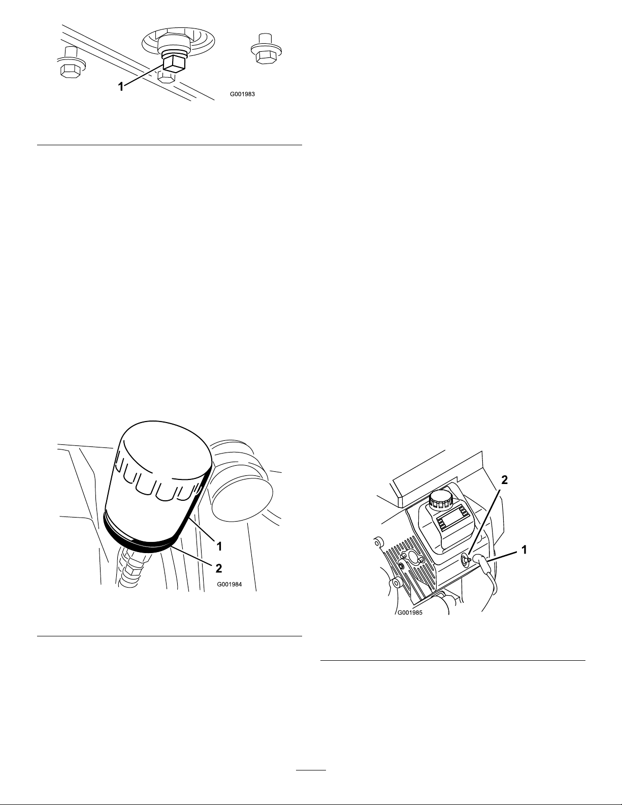
6.Fillthecrankcasewiththecorrecttypeofnewoil;
refertoChangingtheEngineOil,steps8through10.
7.Disposeoftheusedoillteratacertiedrecycling
center.
Figure51
1.Oildrainplug
6.Whentheoilhasdrainedcompletely,replacethe
drainplugandtorqueitto10ft-lb(13.6N-m).
7.Disposeoftheusedoilatacertiedrecyclingcenter.
8.Slowlypourapproximately80%ofthespecied
amountofoilintotheoilllertube(Figure50).
9.Checktheoillevel.
10.Slowlyaddadditionaloiltobringtheoilleveltothe
fullmarkonthedipstick.
Important:Overllingthecrankcasewithoil
maycauseenginedamage.
ChangingtheEngineOilFilter
ServiceInterval:Every100hours
1.Draintheoilfromtheengine;refertoChangingthe
EngineOil.
2.Removetheoillter(Figure52).
ChangingtheSparkPlugs
ServiceInterval:Every200hours
Type:ChampionRC-12YC(orequivalent)
AirGap:0.030inch(0.76mm)
Makesuretheairgapbetweenthecenterandside
electrodesiscorrectbeforeinstallingthesparkplugs.
Useasparkplugwrenchforremovingandinstallingthe
sparkplugsandagappingtool/feelergaugetocheck
andadjusttheairgap.
RemovingtheSparkPlug
1.Settheparkingbrake,stopthepump,stopthe
engine,andremovetheignitionkey .
2.Releasethelatchonthebackoftheseatandliftthe
seatforward.
3.Pullthewiresoffthesparkplugs(Figure53).
4.Cleanaroundthesparkplugstopreventdirtfrom
fallingintotheengineandpotentiallycausing
damage.
Figure52
1.Oillter
2.Filteradapter
3.Wipethelteradaptergasketsurface.
4.Applyathincoatofnewoiltotherubbergasket
onthereplacementlter.
5.Installthereplacementoilltertothelteradapter.
Turntheoillterclockwiseuntiltherubbergasket
contactsthelteradapter,thentightenthelteran
additional1/2turn(
Figure52).
5.Removethesparkplugsandmetalwashers.
Figure53
1.Sparkplugwire2.Sparkplug
CheckingtheSparkPlugs
1.Lookatthecenterofthesparkplugs(Figure54).
Ifyouseealightbrownorgraycoatingonthe
insulator,theengineisoperatingproperly.Ablack
46
Page 47
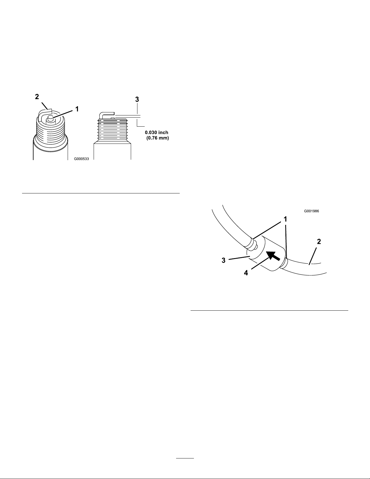
coatingontheinsulatorusuallymeanstheaircleaner
isdirty.
Important:Donotcleanthesparkplugs.
Alwaysreplaceasparkplugwhenithasablack
coating,wornelectrodes,anoilylm,orcracks.
2.Checkthegapbetweenthecenterandsideelectrodes
Figure54)andbendthesideelectrode,ifthegap
(
isnotcorrect.
Figure54
1.Centerelectrodeinsulator3.Airgap(nottoscale)
2.Sideelectrode
FuelSystem
Maintenance
ReplacingtheFuelFilter
ServiceInterval:Every100hours—Replacethefuel
lter.
Every400hours/Yearly(whichever
comesrst)—Inspectthefuellines.
1.Settheparkingbrake,stopthepump,stopthe
engine,andremovetheignitionkey .
2.Releasethelatchonthebackoftheseatandliftthe
seatforward.
3.Clampoffthehoseoneithersideofthefuellter
topreventgasfrompouringoutofthehoseswhen
youremovethelter.
4.Placeadrainpanunderthelter.
5.Squeezetheendsofthehoseclampstogetherand
slidethemawayfromthelter(
Figure55).
InstallingtheSparkPlugs
1.Installthesparkplugsandmetalwashers.
2.Tightenthesparkplugsto18to22ft-lb(24.4to
29.8N-m).
3.Pushthewiresontothesparkplugs(
4.Closeandlatchtheseat.
Figure53).
6.Removethelterfromthefuellines.
Figure55
1.Hoseclamp3.Filter
2.Fuelline4.Flowdirectionarrow
7.Installanewlterandmovethehoseclampsclose
tothelter.
Ensurethattheowdirectionarrowpointstoward
theengine.
DrainingtheFuelTank
ServiceInterval:Every400hours/Yearly(whichever
comesrst)
Drainandcleanthefueltankifthefuelsystembecomes
contaminatedorifyouplantostorethemachinefor
anextendedperiod.Usefresh,cleanfueltoushout
thetank.
1.Transferthefuelfromthetankintoanapprovedfuel
containerusingasiphonpump,orremovethetank
47
Page 48
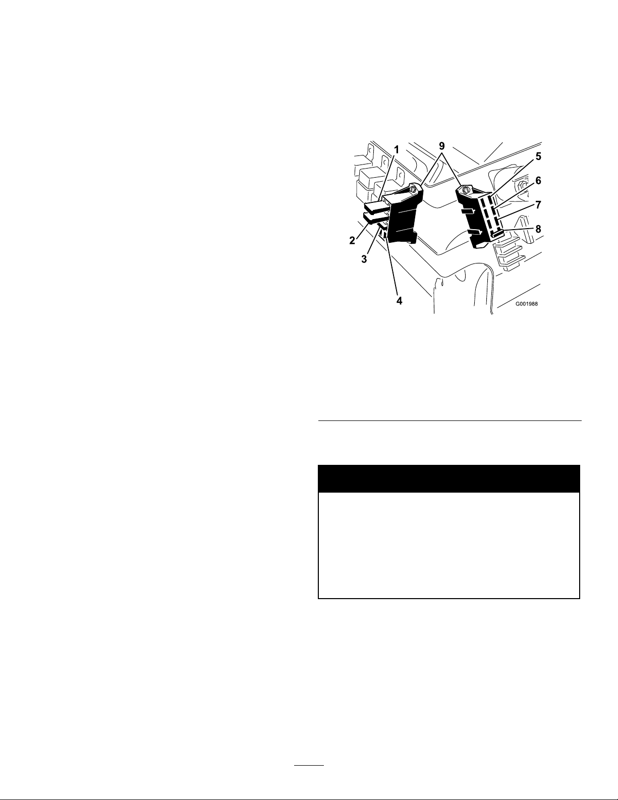
fromthemachineandpourthefueloutofthetank
llspoutintothefuelcontainer.
Note:Ifyouremovethefueltank,youwillneed
toremovethefuelandreturnhosesfromthetank
beforeremovingthetank.
ElectricalSystem
Maintenance
Fuses
2.Replacethefuellter;refertotheReplacingtheFuel
Filtersection.
3.Flushthetankwithfresh,cleanfuel,ifnecessary.
4.Installthetankifyouremoveditinstep1.
5.Fillthetankwithfresh,cleanfuel.
Thereare2fuseblocksand1emptyslotintheelectrical
system.Theyarelocatedbeneaththeseat(Figure56).
Figure56
1.Leftboomactuatorthermal
breaker
2.Rightboomactuator
thermalbreaker
3.Foammarker
4.Openslot
5.Power
6.Headlights
7.Cruisecontrol
8.Spraysystem
9.Fuseblocks
ServicingtheBattery
WARNING
CALIFORNIA
Proposition65Warning
Batteryposts,terminals,andrelated
accessoriescontainleadandleadcompounds,
chemicalsknowntotheStateofCalifornia
tocausecancerandreproductiveharm.
Washhandsafterhandling.
Important:Donotjumpstartthesprayer.
Alwayskeepthebatterycleanandfullycharged.Use
apapertoweltocleanthebatteryandbatterybox.If
thebatteryterminalsarecorroded,cleanthemwitha
solutionoffourpartswaterandonepartbakingsoda.
Applyalightcoatingofgreasetothebatteryterminals
topreventcorrosion.
Voltage:12voltwith280coldcrankingAmps@0
degreesF
48
Page 49
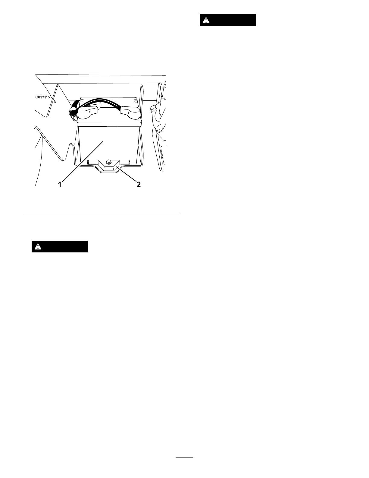
RemovingtheBattery
G0131 15
1
2
1.Positionthesprayeronalevelsurface,settheparking
brake,stopthepump,stoptheengine,andremove
theignitionkey.
2.Thebatteryislocatedontherighthandsideofthe
machinebehindthepump(
Figure57).
WARNING
Batteryterminalsormetaltoolscouldshort
againstmetalsprayercomponentscausing
sparks.Sparkscancausethebatterygassesto
explode,resultinginpersonalinjury .
•Whenremovingorinstallingthebattery,do
notallowthebatteryterminalstotouchany
metalpartsofthesprayer.
•Donotallowmetaltoolstoshortbetween
thebatteryterminalsandmetalpartsofthe
sprayer.
•Alwayskeepthebatterystrapinplaceto
protectandsecurethebattery .
4.Disconnectthepositive(red)cablefromthebattery
post.
Figure57
1.Battery2.Retainer
3.Disconnectthenegative(black)groundcablefrom
thebatterypost.
WARNING
Incorrectbatterycableroutingcoulddamage
thesprayerandcablescausingsparks.Sparks
cancausethebatterygassestoexplode,
resultinginpersonalinjury .
•Alwaysdisconnectthenegative(black)
batterycablebeforedisconnectingthe
positive(red)cable.
•Alwaysreconnectthepositive(red)battery
cablebeforereconnectingthenegative
(black)cable.
5.Removethebatteryretainerandfasteners(
Figure57).
6.Removethebattery.
InstallingtheBattery
ServiceInterval:Every50hours—Checkthebattery
cableconnections.
1.Setthebatteryonthebatteryboxsothatthebattery
postsaretowardthefrontofthesprayer.
2.Installthebatteryretainerandsecureitwiththe
fastenersyouremovedpreviously(Figure57).
Important:Alwayskeepthebatteryretainerin
placetoprotectandsecurethebattery.
3.Connectthepositive(red)cabletothepositive(+)
batterypostandthenegative(black)cabletothe
negative(-)batterypostusingtheboltsandwing
nuts.Slidetherubberbootoverthepositivebattery
post.
4.Installthebatterycoverandsecureitwiththe2
knobs(
Figure57).
CheckingtheElectrolyteLevel
ServiceInterval:Every50hours
Note:Whenthemachineisinstoragecheckthebattery
electrolytelevelevery30days.
1.Loosentheknobsonthesidesofthebatterybox
andremovethebatterycover(Figure57).
2.Removethellercaps.Iftheelectrolyteisnotup
tothellline,addtherequiredamountofdistilled
water;refertoAddingWatertotheBattery.
49
Page 50

DANGER
Batteryelectrolytecontainssulfuricacidwhich
isadeadlypoisonandcausessevereburns.
•Donotdrinkelectrolyteorallowittocontact
yourskin,eyesorclothing .Wearsafety
glassestoshieldyoureyesandrubbergloves
toprotectyourhands.
•Fillthebatterywherecleanwaterisalways
availableforushingtheskin.
AddingWatertotheBattery
Thebesttimetoadddistilledwatertothebatteryisjust
beforeyouoperatethemachine.Thisletsthewatermix
thoroughlywiththeelectrolytesolution.
1.Cleanthetopofthebatterywithapapertowel.
2.Removethellercapsfromthebatteryandslowly
lleachcellwithdistilledwateruntilthelevelisup
tothellline.Replacethellercaps.
Important:Donotoverllthebattery.
Electrolytewilloverowontootherpartsofthe
sprayerandseverecorrosionanddeterioration
willresult.
itontheshelforonthemachine.Leavethecables
disconnectedifitisstoredonthemachine.Storethe
batteryinacoolatmospheretoavoidquickdeterioration
ofthechargeinthebattery.Topreventthebatteryfrom
freezing,makesureitisfullycharged.
ChargingtheBattery
Important:Alwayskeepthebatteryfullycharged
(1.260specicgravity).Thisisespeciallyimportant
topreventbatterydamagewhenthetemperatureis
below32degreesF(0degreesC).
1.Removethebatteryfromthechassis;referto
RemovingtheBattery.
2.Checktheelectrolytelevel;refertoCheckingthe
ElectrolyteLevel.
3.Connecta3to4ampbatterychargertothebattery
posts.Chargethebatteryatarateof3to4amperes
for4to8hours(12volts).Donotoverchargethe
battery.
WARNING
Chargingthebatteryproducesgassesthatcan
explode.
Neversmokenearthebatteryandkeepsparks
andamesawayfrombattery.
4.Installthebatteryinthechassis;refertoInstalling
theBattery.
StoringtheBattery
Ifthemachinewillbestoredformorethan30days,
removethebatteryandchargeitfully.Eitherstore
50
Page 51
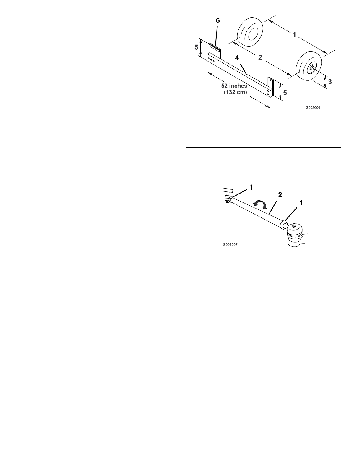
DriveSystem
Maintenance
InspectingtheWheels/Tires
ServiceInterval:Beforeeachuseordaily—Checkthe
tirepressure.
Aftertherst8hours—T orquethe
wheellugnuts.
Every100hours—Torquethewheel
lugnuts.
Every100hours—Inspectthe
conditionandwearofthetires.
Checkthetirepressureevery8hoursordailytoensure
properlevels.Fillthetiresto18psi(124kPa).Also,
checkthetiresforwearordamage.
Checkthewheelstoensurethattheyaremounted
securelyaftertherst8operatinghoursandthen
every100hoursthereafter.Torquethefrontbolts
to50-55ft-lb(68-74N-m)andtherearlugnutsto
40-60ft-lb(54-81N-m).
Figure58
1.Tirecenterline-back4.Fixture
2.Tirecenterline-front
3.Axlecenterline
5.Ifthemeasurementdoesnotfallwithinthespecied
range,loosenthejamnutsatbothendsofthetie
rods(Figure59).
5.Axlecenterlinedistance
6.6inches(15cm)ruler
Checkthetireconditionatleastevery100hours
ofoperation.Operatingaccidents,suchashitting
curbs,candamageatireorrimandalsodisruptwheel
alignment,soinspecttireconditionafteranaccident.
AdjustingtheFrontWheel
Toe-In
ServiceInterval:Every100hours/Yearly(whichever
comesrst)
Thetoe-inshouldbe0to1/4inch(0to6mm).
1.Fillthetankwithapproximately80USgallons
(303L)ofwater.
2.Checkandllalltires;refertoCheckingTire
Pressure.
3.Drivethesprayerbackandforthafewtimestorelax
theA-arms,thendriveitforwardatleast10ft(3m).
4.Measurethedistancebetweenbothofthefronttires
attheaxleheightatboththefrontandrearofthe
fronttires(Figure58).Axtureoralignmentgauge
isneededfortherearmeasurementofthefronttires
ataxleheight.Usethesamextureoralignment
gaugetoaccuratelymeasurethefrontofthefront
tiresataxleheight(Figure58).
Figure59
1.Jamnut2.Tierod
6.Rotatebothtierodstomovethefrontofthetire
inwardoroutward.
Note:Thetierodsshouldbethesamelengthwhen
youarenished.
7.Tightenthetierodjamnutswhentheadjustmentis
correct.
8.Ensurethatthereisfulltravelofthesteeringwheel
inbothdirections.
Thefrontofthetiresshouldbe0to1/4inch(0to
6mm)closerthanthebacksideofthefronttires.
51
Page 52
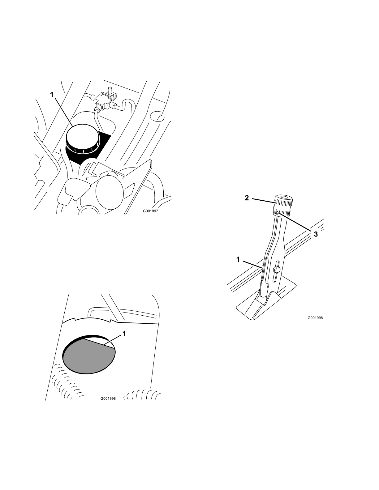
BrakeMaintenance
CheckingtheBrakeFluid
Thebrakeuidreservoirisshippedfromthefactory
lledwithDOT3brakeuid.Checkthelevelbefore
startingtheengineeachday .
InspectingtheBrakes
ServiceInterval:Every100hours
Thebrakesareacriticalsafetycomponentofthesprayer.
Inspectthemasfollows:
•Inspectthebrakeshoesforwearordamage.Ifthe
lining(brakepad)thicknessislessthan1/16inch
(1.6mm),replacethebrakeshoes.
•Inspectthebackingplateandothercomponents
forsignsofexcessivewearordeformation.If
anydeformationisfound,replacetheappropriate
components.
AdjustingtheParkingBrake
ServiceInterval:Every200hours—Checktheparking
brake.
1.Loosenthesetscrewsecuringtheknobtothe
parkingbrakelever(
Figure62).
Figure60
1.Brakeuidreservoir
1.Positionthesprayeronalevelsurface,settheparking
brake,stopthepump,stoptheengine,andremove
theignitionkey.
2.TheuidlevelshouldbeuptotheFulllineonthe
reservoir(Figure61).
Figure62
1.Parkingbrakelever
2.Knob
2.Rotatetheknobuntilaforceof35-45lbisrequired
toactuatelever.
3.Tightenthesetscrew.
3.Setscrew
Figure61
1.Fullline
3.Iftheuidlevelislow ,cleantheareaaroundthe
reservoircap,removethecap,andllthereservoir
totheproperlevel.Donotoverll.
52
Page 53
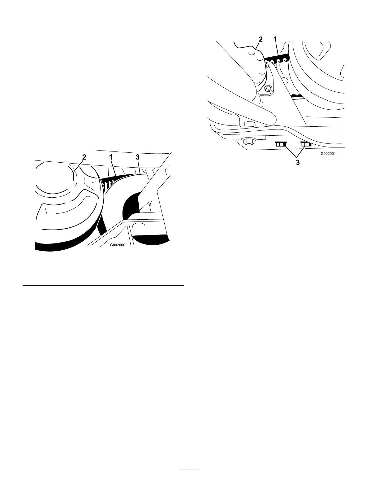
BeltMaintenance
ServicingtheDriveBelt
CheckingtheDriveBelt
ServiceInterval:Aftertherst8hours
Every200hours
1.Positionthesprayeronalevelsurface,setthe
parkingbrake,movetherangeselectortotheNeutral
position,stopthepump,stoptheengine,andremove
theignitionkey.
2.Rotateandinspectthedrivebeltforexcessivewear
ordamage.Replacethebeltifnecessary.
2.Loosenthesteeringpumpmountingbolts
(Figure64).
Figure64
1.Steeringpumpbelt3.Steeringpumpmounting
bolts
2.Steeringpump
Figure63
1.Drivebelt
2.Primaryclutch
3.Secondaryclutch
ReplacingtheDriveBelt
1.Rotateandroutethebeltoverthesecondaryclutch
(Figure63).
2.Removethebeltfromtheprimaryclutch.
3.Placethenewbeltovertheprimaryclutch.
4.Rotateandinstallitoverthesecondaryclutch.
AdjustingtheSteeringPump
Belt
3.Movethepumpuntilthebeltexes1/4inch(5mm)
with5lb.offorce(22N)thentightenthemounting
bolts,startingwiththeboltclosesttotheengine
crankshaft.
ServiceInterval:Aftertherst8hours
Every100hours
Thebeltshouldex1/4inch(5mm)when5lbofforce
(22N)isappliedmidwayonthetopspan.
1.Parkthemachineonalevelsurface,settheparking
brake,turntheignitionoff,andremovethekey.
53
Page 54
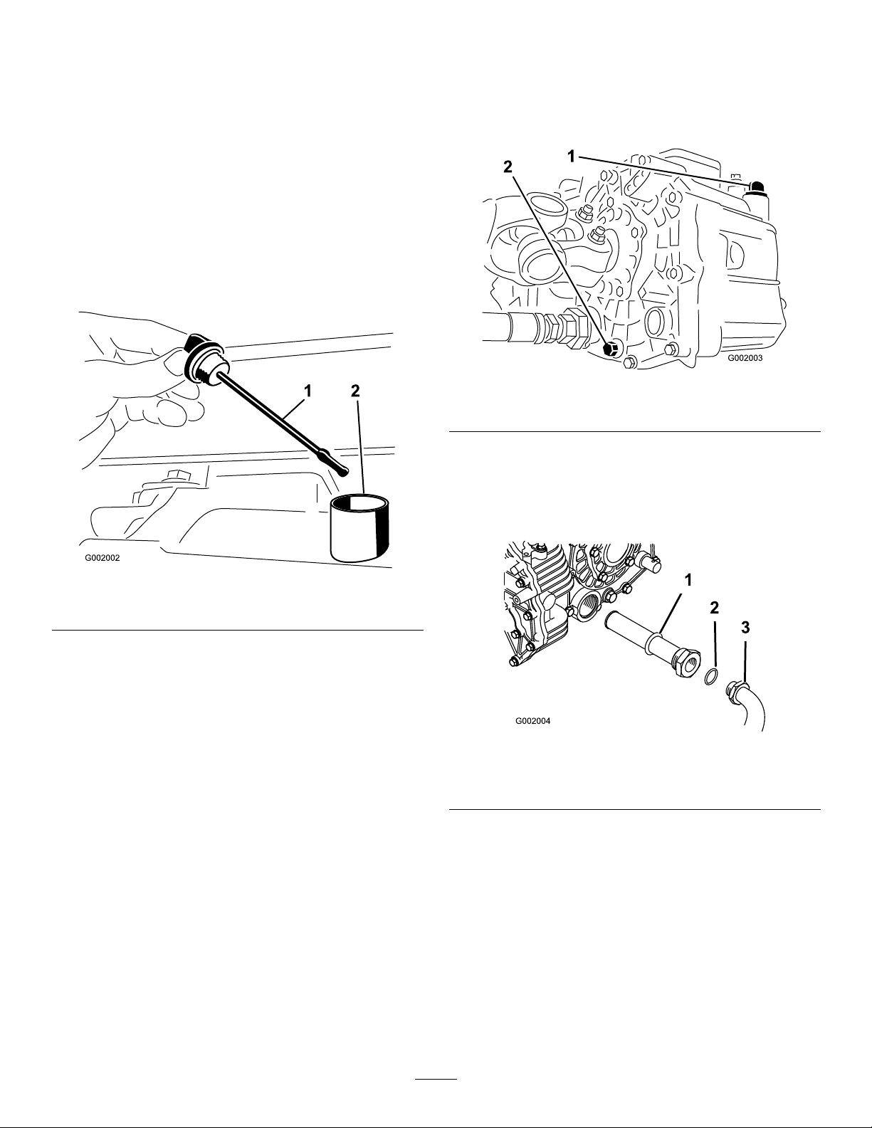
HydraulicSystem
Maintenance
Checkingthe
Transaxle/HydraulicFluid
ServiceInterval:Every200hours
1.Positionthesprayeronalevelsurface,settheparking
brake,stopthepump,stoptheengine,andremove
theignitionkey.
2.Removethetransaxledipstickandwipeitwitha
cleanrag(Figure65).
2.Placeadrainpanunderthedrainplugofthe
reservoir.
3.Removethedrainplugfromthesideofthereservoir
andletthehydraulicuidowintothedrainpan
(Figure66).
Figure66
1.Hydraulicdipstick2.Drainplug
4.Notetheorientationofthehydraulichoseand90
degreesttingconnectedtothestrainer.
Figure65
1.Dipstick2.Fillhole
Important:Beverycarefulnottogetdirtor
othercontaminantsintotheopeningwhen
checkingthetransmissionoil.
3.Insertthedipstickintothetubeandmakesureitis
seatedfully.Removethedipstickandchecktheoil
level.
4.Thetransaxleuidlevelshouldbeatthetopof
theatportionofthedipstick.Ifitisnot,ll
thereservoirwiththeappropriateuid;referto
ChangingtheTransaxle/HydraulicFluid.
5.Installthedipstickrmlyinplace.
ChangingTransaxle/Hydraulic
5.Removethehydraulichoseand90degreestting
(Figure67).
Figure67
1.Hydraulicstrainer
2.O-ring
6.Removethestrainerandcleanitbybackushing
itwithacleandegreaser.
7.Allowthestrainertoairdry.
8.Installthestrainerwhentheoilisdraining.
3.90degreestting
Fluid
ServiceInterval:Every800hours/Yearly(whichever
comesrst)
1.Positionthesprayeronalevelsurface,settheparking
brake,stopthepump,stoptheengine,andremove
theignitionkey.
9.Installthehydraulichoseand90degreesttingto
thestrainer.
10.Installandtightenthedrainplug.
11.Fillthereservoirwithapproximately7.5qt.of
DexronIIlATF .
54
Page 55
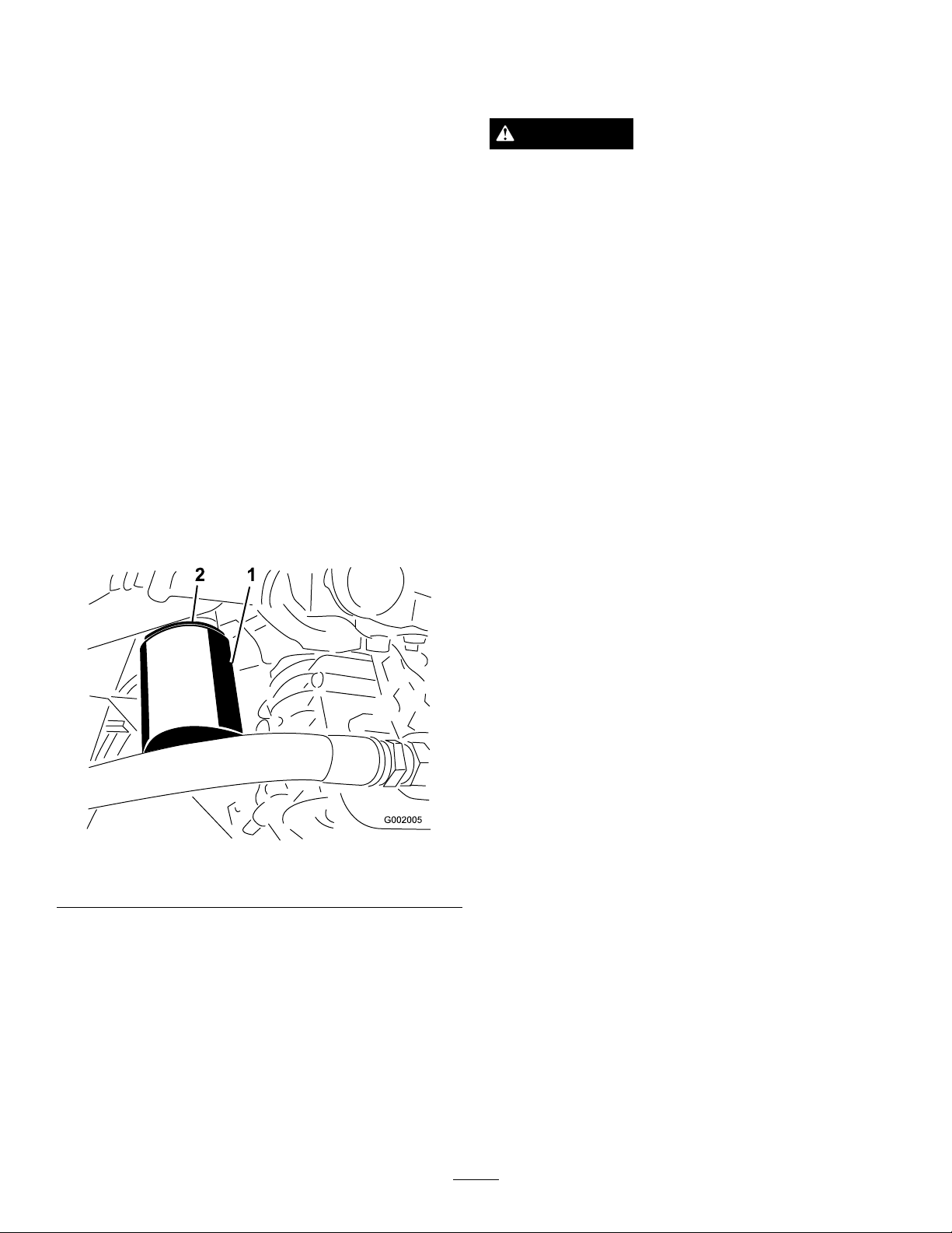
Important:Useonlythehydraulicuids
specied.Otheruidscouldcausesystem
damage.
12.Starttheengineanddrivethesprayertollthe
hydraulicsystem.Rechecktheoillevelandreplenish
it,ifrequired.
ReplacingtheHydraulicFilter
ServiceInterval:Aftertherst8hours
Every800hours/Yearly(whichever
comesrst)
UsetheTororeplacementlter(PartNo.54-0110).
Important:Useofanyotherltermayvoidthe
warrantyonsomecomponents.
1.Positionthesprayeronalevelsurface,settheparking
brake,stopthepump,stoptheengine,andremove
theignitionkey.
2.Cleantheareaaroundtheltermountingarea.
3.Placeadrainpanunderthelter.
4.Removethelter(
Figure68).
SpraySystem
Maintenance
WARNING
Chemical substances used in the spray system may
be hazardous and to xic to y ou, bystander s, animals,
plants, soils or other pr oper ty .
•Carefullyreadandfollowthechemical
warninglabelsandMaterialSafetyData
Sheets(MSDS)forallchemicalsusedand
protectyourselfaccordingtothechemical
manufacturer’srecommendations.Forexample,
useappropriatePersonalProtectiveEquipment
(PPE)includingfaceandeyeprotection,gloves,
orotherequipmenttoguardagainstpersonal
contactwiththechemical.
•Keepinmindthattheremaybemorethanone
chemicalusedandinformationoneachshould
beassessed.
R efuse to operate or w or k on the spray er if this
•
inf or mation is not a v aila ble!
•Beforeworkingonaspraysystemmakesurethe
systemhasbeentriplerinsedandneutralized
accordingtotherecommendationsofthe
chemicalmanufacturer(s).
•Verifythereisanadequatesupplyofcleanwater
andsoapnearby,andimmediatelywashoffany
chemicalsthatcontactyou.
Figure68
1.Hydrauliclter2.Gasket
5.Lubricatethenewltergasket.
6.Ensurethattheltermountingareaisclean.
7.Screwthelteronuntilthegasketcontactsthe
mountingplate,thentightenthelterone-halfturn.
8.Starttheengineandletitrunforabouttwominutes
topurgeairfromthesystem.Stoptheengineand
checkthehydraulicoillevelandforleaks.
InspectingtheHoses
ServiceInterval:Every200hours—Inspectallhoses
andconnectionsfordamageand
properattachment.
Examineeachhoseinthespraysystemforcracks,
leaksorotherdamage.Atthesametime,inspectthe
connectionsandttingsforsimilardamage.Replaceany
hosesandttingsifdamaged.
PumpMaintenance
InspectingthePump
ServiceInterval:Every400hours/Yearly(whichever
comesrst)—Inspectthepump
diaphragmandreplaceifnecessary.
(seeanAuthorizedToroService
Distributor)
Every400hours/Yearly(whichever
comesrst)—Inspectthepressure
dampenerbladderandreplaceif
55
Page 56
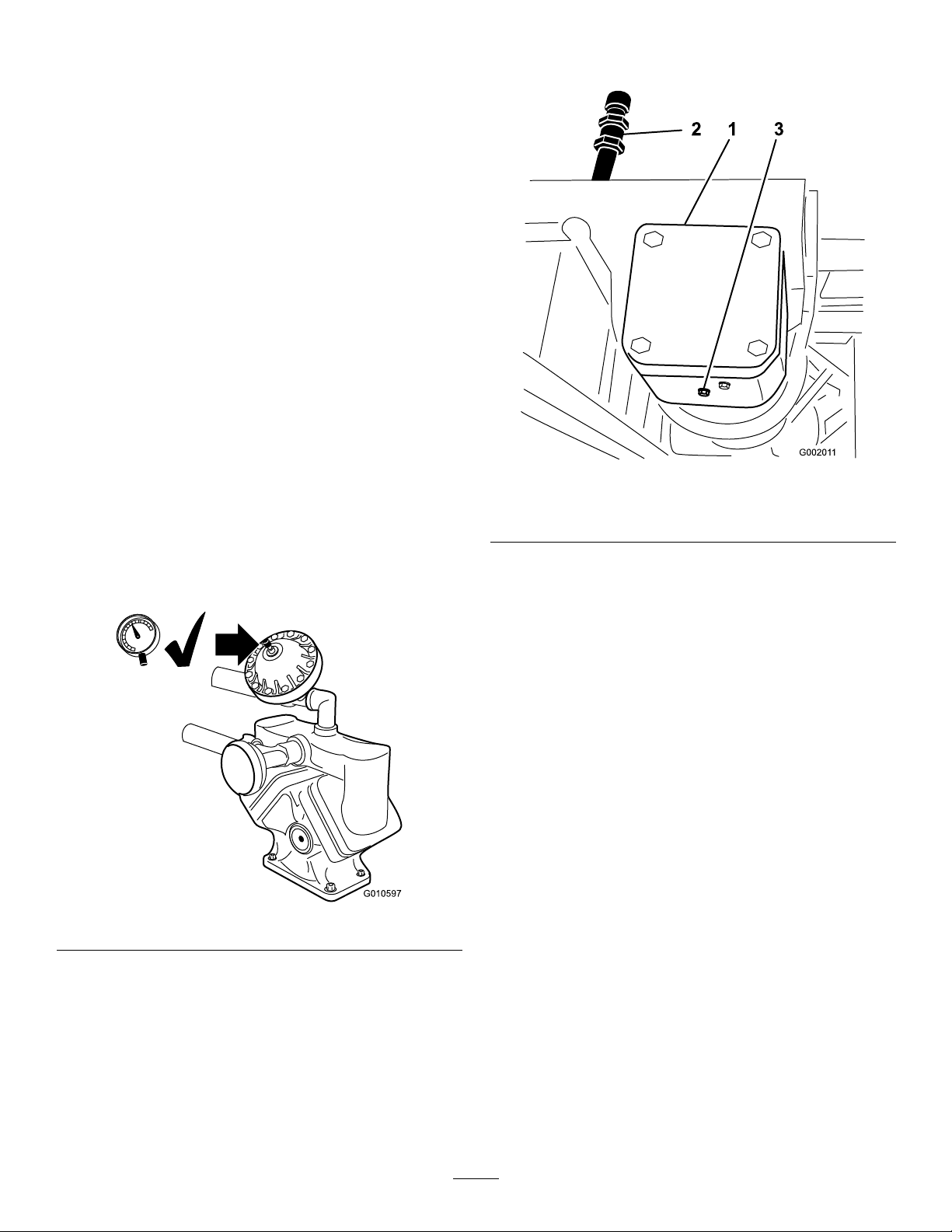
necessary.(seeanAuthorizedToro
G010597
ServiceDistributor)
Every400hours/Yearly(whichever
comesrst)—Inspectthepump
checkvalvesandreplaceifnecessary.
(seeanAuthorizedToroService
Distributor)
Note:Thefollowingmachinecomponentsare
consideredpartssubjecttoconsumptionthroughuse
unlessfounddefectiveandarenotcoveredbythe
Warrantyassociatedwiththismachine.
HaveanAuthorizedToroServiceDistributorcheck
followinginternalpumpcomponentsfordamage:
•Pumpdiaphragm
•Pressuredampenerbladder
•Pumpcheckvalvesassemblies
Replaceanycomponentsifnecessary.
2.Placeapanunderthedrainplugonthepumpdrive
gearbox(Figure70).
AdjustingtheAirPressureinDampener
Theairpressureinthedampeneronthepumpissetat
15psi(1bar)bythemanufacturer.Therecommended
pressureinthedampeneris1/3ofthesprayingpressure.
Ifusingaspraypressuregreaterthan45psi(3.1bar)
adjustthedampeneraccordingly.
Figure69
Figure70
1.Pumpdrivegearbox3.Drainplug
2.Filltube
3.Removethellpluganddrainplug(Figure70),
allowingtheoiltodrainintothepan.
4.Installandtightenthedrainplugwhentheuid
stopsdraining.
5.Addapproximately1quart(1L)ofMobilSHC634
SyntheticLubricanttothelltube.
Important:UseonlyMobilSHC634Synthetic
Lubricantorequivalentsyntheticuidinthe
gearbox.Non-syntheticoilsmaybreakdown
causingdamagetothepumpgearbox.
6.Installthellplug.
AdjustingtheBoomActuator
ServiceInterval:Every400hours—Checkboom
actuatorhydraulicoilforairbubbles.
ChangingthePumpDriveGearbox
Fluid
ServiceInterval:Every400hours/Yearly(whichever
comesrst)
1.Positionthesprayeronalevelsurface,settheparking
brake,stopthepump,stoptheengine,andremove
theignitionkey.
1.Positionthesprayeronalevelsurface,lowerthe
boomsintothesprayposition.
2.Settheparkingbrake,stopthepump,stopthe
engine,andremovetheignitionkey
3.Attempttolifttheboombyapplyingamoderate
amountofpressure(justenoughtolifttheboom
manually)whileobservingtheactuatorrod.Ifthe
actuatorrodexhibitsmovementrefertobelow.
4.Repeattheprocedurefortheopposingboom.
56
Page 57
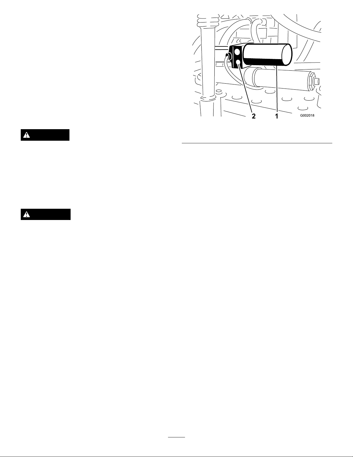
Iftheactuatorrodexhibitsanaxialmovement(travels
intooroutofthecylinder)greaterthan0.085-0.100inch
(2.16-2.54mm),youmaywishtobleedtheairfromthe
hydraulicoil.
RefertotheServiceManualforinstructionsonhowto
bleedairfromtheactuatorsorcontactanAuthorized
ToroServiceDistributor.
EmergencyManualOperation
oftheBoomActuators
Note:Determinetheleftandrightsidesofthemachine
fromthenormaloperatingposition.
DANGER
Useofthemanualreliefvalvemaycausetheboom
tomovesuddenlyandcauseinjurytoyouorothers.
•Takecautionandadjustthemanualreliefvalve
slowly.
•Ensurethesurroundingareaisclearandnoone
isinsidetheoperatingrangeoftheboom.
CAUTION
Adjustingthemanualreliefvalvewithelectrical
powerpresentcouldcausetheactuatoroperate
irregularlyandcauseinjurytoyouorothers.
Figure71
1.Actuator,rightboom
Note:Duetotheopposingorientationofactuators
inrespecttoeachotherthemanualreliefvalveison
theforwardfaceoftheleftboomactuatorandthe
rearfaceoftherightboomactuator.
2.Useahexagonalwrenchtoloosenthemanualrelief
valvenomorethan2-3turns.Thecylindershould
startstrokingmanuallyorbyexternalpressureatthis
time.
3.Oncetheoriginalpositionoftheactuatoris
recovered,closethemanualreliefvalve.T orquethe
valveto1.1-2.1ft-lb(1.5-2.9N-m).
2.Manualreliefvalve
Do not
powerisbeingsuppliedtotheactuator.
Incaseofanemergencysuchthattheboommustbe
movedandno12VDCpowersourceisavailable,the
manualreliefvalvecanbeusedtorelievepressurewithin
theactuatorandallowtheboomstobemovedmanually.
Important:Themanualvalvemustnotbeloosened
morethan4turns.Turningthevalvemorethan4
turnsmaycausethevalvetocomeoffcompletely
allowinghydraulicoiltospillout.
1.Locatethemanualreliefvalveontheactuatorfor
usethemanualreliefvalvewhileelectrical
eachboom.Themanualreliefvalveisthesmaller
valveandisonlyononesideoftheactuatorbody
Figure71).
(
InspectingtheNylonPivot
Bushings
ServiceInterval:Every400hours/Yearly(whichever
comesrst)
1.Positionthesprayeronalevelsurface,settheparking
brake,stopthepump,stoptheengine,andremove
theignitionkey.
2.Extendtheboomstothespraypositionandsupport
theboomsusingstandsorstrapsfromalift.
3.Withtheweightoftheboomsupported,remove
theboltandnutsecuringthepivotpintotheboom
assembly(
Figure72).Removethepivotpin.
57
Page 58
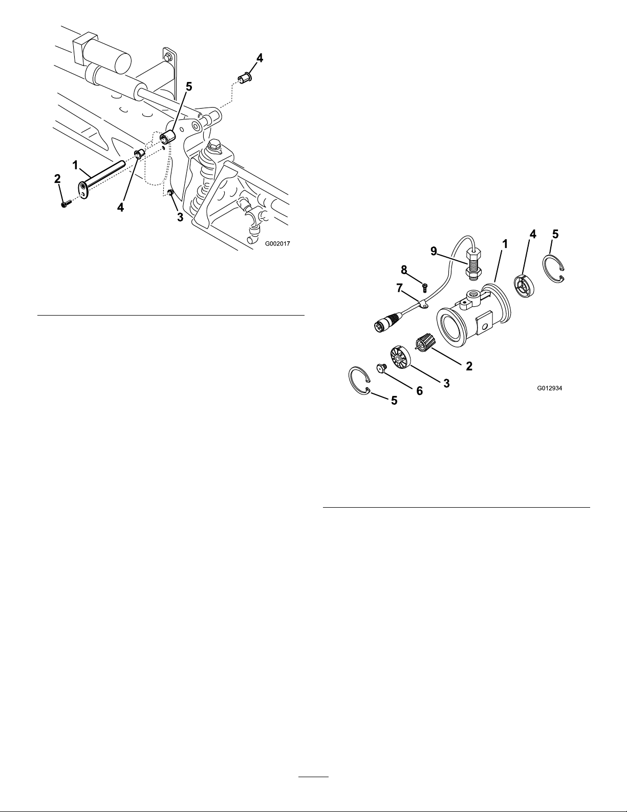
G002017
2
3
1
4
4
5
Figure72
G012934
8
7
9
1
4 5
2
3
6
5
1.Pivotpin4.Nylonbushing
2.Bolt5.Pivotbracket
3.Nut
4.Removetheboomandpivotbracketassemblyfrom
thecenterframetoaccessthenylonbushings.
Cleaning
CleaningtheFlowmeter
ServiceInterval:Every200hours/Yearly(whichever
comesrst)(Moreoftenwhenusing
wettablepowders)
1.Thoroughlyrinseanddraintheentirespraying
system.
2.Removetheowmeterfromthesprayerandush
itwithcleanwater.
3.Removetheretainerringontheupstreamside
Figure73).
(
5.Removeandinspectthenylonbushingsfromthe
frontandbacksidesofthepivotbracket(
Figure72).
Replaceanydamagedbushings.
6.Placeasmallamountofoilonthenylonbushings
andinstallthemintopivotbracket.
7.Installtheboomandpivotbracketassemblyintothe
centerframe,aligningtheopenings(
Figure72).
8.Installthepivotpinandsecureitwiththeboltand
nutremovedpreviously.
Repeattheprocedureforeachboom.
Figure73
1.Modiedangedbody
2.Rotor/magnetassembly7.Cableclamp
3.Hub/bearingassembly
4.Hubassembly(with
keywayup)
5.Retainingring10.Flow-reducingsleeve
6.Turbinestudassembly
8.Threadscrew
9.Sensorassembly
4.Cleantheturbineandtheturbinehubtoremove
metallingsandanywettablepowders.
5.Inspecttheturbinebladesforwear.
Note:Holdtheturbineinyourhandandspinit.
Itshouldspinfreelywithverylittledrag.Ifitdoes
not,replaceit.
6.Assembletheowmeter.
7.Usealowpressure(5psior50kPa)airjettoensure
thattheturbinespinsfreely .Ifitdoesnot,loosen
thehexstudonthebottomoftheturbinehubby
1/16ofaturnuntiltheturbinespinsfreely.
CleaningtheSuctionStrainer
ServiceInterval:Beforeeachuseordaily(moreoften
whenusingwetablepowders)
58
Page 59
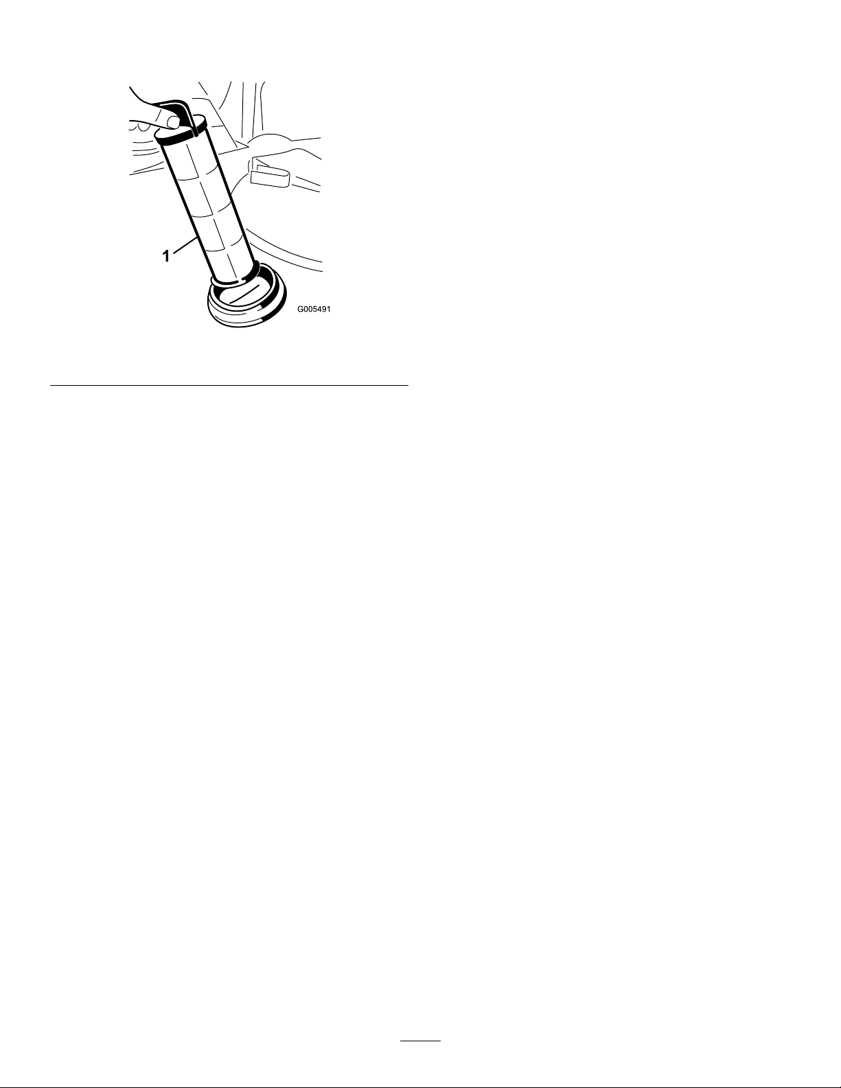
1.Removetheretainerfromtheredttingattachedto
thelargehoseonthetopofthetank.
Figure74
1.Suctionstrainer
2.Disconnectthehosefromthetank.
3.Pullthestraineroutofthehole.
4.Cleanthestrainerwithcleanrunningwater.
5.Replacethestrainer,seatingitfullyintothehole.
6.Connectthehosetothetopofthetankandsecure
itwiththeretainer.
Storage
1.Positionthesprayeronalevelsurface,settheparking
brake,stopthepump,stoptheengine,andremove
theignitionkey.
2.Cleandirtandgrimefromtheentiremachine,
includingtheoutsideoftheengine’scylinderhead
nsandblowerhousing.
Important:Youcanwashthemachinewith
milddetergentandwater.Donotusehigh
pressurewatertowashthemachine.Pressure
washingmaydamagetheelectricalsystemor
washawaynecessarygreaseatfrictionpoints.
Avoidexcessiveuseofwater,especiallynearthe
controlpanel,lights,engine,andthebattery.
3.Cleanthespraysystem;refertotheCleaningthe
SprayersectioninOperation.
4.Addarustinhibiting,non-alcoholbased,RV
antifreezesolutiontothesystemandrunthepump
forafewminutestocirculateitthroughthesystem,
thendrainthespraysystemascompletelyaspossible.
5.Usetheboomliftswitchestoraisethebooms.Raise
theboomsuntiltheyhavemovedcompletelyinto
boomtransportcradleformingthe“X”transport
positionandtheboomcylindersarefullyretracted.
Makesuretheboomcylindersarefullyretractedto
preventactuatorroddamage.
6.Inspectthebrakes;refertoInspectingtheBrakesin
theBrakeMaintenancesection.
7.Servicetheaircleaner;refertoServicingtheAir
CleanerintheEngineMaintenancesection.
8.Greasethesprayer;refertotheLubricationsection.
9.Changethecrankcaseoil;refertoServicingEngine
OilintheEngineMaintenancesection.
10.Checkthetirepressure;refertoCheckingtheTire
PressureintheDriveSystemMaintenancesection.
11.Forstorageover30days,preparethefuelsystem
asfollows:
A.Addapetroleumbasedstabilizer/conditionerto
fuelinthetank.
Followmixinginstructionsfromstabilizer
manufacturer.(1oz.pergallon).Donotusean
alcoholbasedstabilizer(ethanolormethanol).
Note:Afuelstabilizer/conditionerismost
effectivewhenmixedwithfreshgasolineand
usedatalltimes.
B.Runtheenginetodistributeconditionedfuel
throughthefuelsystem(5minutes).
59
Page 60

C.Stoptheengine,allowittocool,anddrainthe
fueltank.
21.Storethemachineinaclean,drygarageorstorage
area.
D.Restarttheengineandrunituntilitstops.
E.Choketheengine.
F.Startandruntheengineuntilitwillnotstart
again.
G.Disposeoffuelproperly.Recycleasperlocal
codes.
Important:Donotstore
stabilizer/conditionedgasolineover90
days
12.Removethesparkplugsandchecktheircondition;
refertoChangingSparkPlugsintheEngine
Maintenancesection.
13.Withthesparkplugsremovedfromtheengine,pour
twotablespoonsofengineoilintothesparkplug
hole.
14.Usetheelectricstartertocranktheengineand
distributetheoilinsidethecylinder.
15.Installthesparkplugsandtightentorecommended
torque;refertoChangingSparkPlugsintheEngine
Maintenancesection.
22.Removetheignitionkeyandputitinasafeplaceout
ofthereachofchildren.
23.Coverthemachinetoprotectitandkeepitclean.
Note:Donotinstallthewireonthesparkplug(s).
16.Removethebatteryfromthechassis,checkthe
electrolytelevel,andchargeitfully;refertoServicing
theBatteryintheElectricalSystemMaintenance
section.
Note:Donotconnectthebatterycablestothe
batterypostsduringstorage.
Important:Thebatterymustbefullycharged
topreventitfromfreezingandbeingdamaged
attemperaturesbelow32degreesF(0degreesC).
Afullychargedbatterymaintainsitschargefor
about50daysattemperatureslowerthan40
degreesF(4degreesC).Ifthetemperatureswill
beabove40degreesF(4degreesC),checkthe
waterlevelinthebatteryandchargeitevery30
days.
17.Checkandtightenallbolts,nuts,andscrews.Repair
orreplaceanypartthatisdamaged.
18.Checktheconditionofallsprayhoses,replacingany
thataredamagedorworn.
19.Tightenallhosettings.
20.Paintallscratchedorbaremetalsurfaces.
PaintisavailablefromyourAuthorizedService
Dealer.
60
Page 61

Troubleshooting
TroubleshootingtheEngineandVehicle
Problem
Thestarterdoesnotcrank.
Theenginecranks,butwillnotstart.
Theenginestarts,butdoesnotkeep
running.
PossibleCauseCorrectiveAction
1.Therangeselectorisinagearother
thanNeutral.
2.Theelectricalconnectionsarecorroded
orloose.
3.Afuseisblownorloose.3.Correctorreplacefuse.
4.Thebatteryisdischarged.
5.Thesafetyinterlocksystemis
malfunctioning.
6.Abrokenstarterorstartersolenoid.
7.Seizedinternalenginecomponents.7.ContactyourAuthorizedService
1.Thefueltankisempty.1.Fillwithfreshfuel.
2.Dirt,water,orstalefuelisinthefuel
system.
3.Cloggedfuelline.3.Cleanorreplace.
4.Thesparkplugleadisdisconnected.4.Reconnectthesparkplug.
5.Asparkplugisdamagedordirty .5.Replacethesparkplug.
6.Thekillrelayisnotenergized.
7.Theignitionisbroken.
1.Thefueltankventisrestricted.1.Replacethefuelcap.
2.Dirtorwaterinthefuelsystem.2.Drainandushthefuelsystem;add
3.Thefuellterisclogged.3.Replacethefuellter.
4.Afuseisblownorloose.4.Correctorreplacefuse.
5.Thefuelpumpisbroken.5.ContactyourAuthorizedService
6.Thecarburetorisbroken.
7.Loosewiresorpoorconnections.
8.Thecylinderheadgasketisbroken.
1.Pressthebrakepedalandmovethe
rangeselectortotheNeutralposition.
2.Checktheelectricalconnectionsfor
goodcontact.
4.Chargeorreplacethebattery .
5.ContactyourAuthorizedService
Dealer.
6.ContactyourAuthorizedService
Dealer.
Dealer.
2.Drainandushthefuelsystem;add
freshfuel.
6.ContactyourAuthorizedService
Dealer.
7.ContactyourAuthorizedService
Dealer.
freshfuel.
Dealer.
6.ContactyourAuthorizedService
Dealer.
7.Checkandtightenwireconnections.
8.ContactyourAuthorizedService
Dealer.
Theengineruns,butknocksormisses.
1.Dirt,water,orstalefuelisinthefuel
system.
2.Asparkplugleadisloose.2.Reconnectthesparkpluglead.
3.Asparkplugisbroken.3.Replacethesparkplug.
4.Loosewiresorpoorconnections.
5.Engineoverheating.
1.Drainandushthefuelsystem;add
freshfuel.
4.Checkandtightenwireconnections.
5.SeeEngineOverheats.
61
Page 62

Problem
PossibleCauseCorrectiveAction
Theenginewillnotidle.
Theengineoverheats.
Theenginelosespower.
1.Thefueltankventisrestricted.1.Replacethefuelcap.
2.Dirt,water,orstalefuelisinthefuel
system.
3.Asparkplugisdamagedorbroken.3.Replacethesparkplug.
4.Carburetoridlepassagesareplugged.4.ContactyourAuthorizedService
5.Theidlespeedadjustingscrewis
incorrectlyset.
6.Thefuelpumpisbroken.6.ContactyourAuthorizedService
7.Lowcompression.
8.Theaircleanerelementisdirty.
1.Thecrankcaseoillevelisincorrect.
2.Excessiveloading.2.Reduceload;uselowergroundspeed.
3.Theairintakescreensaredirty.
4.Thecoolingnsandairpassages
undertheengineblowerhousing
and/ortherotatingairintakescreenare
plugged.
5.Thefuelmixtureislean.5.ContactyourAuthorizedService
1.Thecrankcaseoillevelisincorrect.
2.Theaircleanerelementisdirty.
3.Dirt,water,orstalefuelisinthefuel
system.
4.Theengineisoverheated.
5.Asparkplugisdamagedordirty .5.Replacethesparkplug.
6.Theventholeinthefueltankvent
ttingisplugged.
7.Lowcompression.
2.Drainandushthefuelsystem;add
freshfuel.
Dealer.
5.ContactyourAuthorizedService
Dealer.
Dealer.
7.ContactyourAuthorizedService
Dealer.
8.Cleanorreplace.
1.Fillordraintothefullmark.
3.Cleanwitheveryuse.
4.Cleanwitheveryuse.
Dealer.
1.Fillordraintothefullmark.
2.Cleanorreplace.
3.Drainandushthefuelsystem;add
freshfuel.
4.SeeEngineOverheats.
6.Replacethefuelcap.
7.ContactyourAuthorizedService
Dealer.
Themachinewillnotoperateorissluggish
ineitherdirectionbecausetheengine
bogsdownorstalls.
Themachinewillnotoperateineither
direction.
1.Theenginemountingboltsareloose.1.Tightentheenginemountingbolts. Abnormalvibrationornoise.
2.Thereisaproblemwiththeengine.
1.Theparkingbrakeisset.1.Releasetheparkingbrake.
1.TherangeselectorisintheNeutral
position.
2.Theparkingbrakewasnotreleasedor
theparkingbrakeisnotreleasing.
3.Thetransmissionisbroken.
4.Thecontrollinkageneedsadjustment
orreplacement.
5.Thedriveshaftorwheelhubkeyhas
beendamaged.
2.ContactyourAuthorizedService
Dealer.
1.Pressthebrakeandshifttherange
selectorintoagear.
2.Releasetheparkingbrakeorcheckthe
linkage.
3.ContactyourAuthorizedService
Dealer.
4.ContactyourAuthorizedService
Dealer.
5.ContactyourAuthorizedService
Dealer.
62
Page 63

TroubleshootingtheSpraySystem
Problem
Aboomsectiondoesnotspray.
Aboomsectiondoesnotturnoff.
Aboomvalveisleaking
Apressuredropoccurswhenyouturnon
aboom.
PossibleCauseCorrectiveAction
1.Theelectricalconnectionontheboom
valveisdirtyordisconnected.
2.Blownfuse2.Checkthefusesandreplacethemas
3.Pinchedhose3.Repairorreplacethehose.
4.Aboomby-passvalveisimproperly
adjusted.
5.Damagedboomvalve
6.Damagedelectricalsystem
1.Thevalveisdamaged.
1.AnO-ringisdeteriorated.1.Stopthespraysystemandpumpand
1.Theboombypassvalveisimproperly
adjusted.
2.Thereisanobstructionintheboom
valvebody.
3.Anozzlelterisdamagedorclogged.
1.Turnthevalveoffmanually .Disconnect
theelectricalconnectoronthevalve
andcleanallleads,thenreconnectit.
necessary.
4.Adjusttheboomby-passvalves.
5.ContactyourAuthorizedService
Dealer.
6.ContactyourAuthorizedService
Dealer.
1.Stopthespraysystemandpump
andturnoffthesprayer.Removethe
retainerfromundertheboomvalveand
pulloutthemotorandstem.Inspect
allpartsandreplaceanythatappear
damaged.
turnoffthesprayer.Disassemblethe
valveandreplacetheO-rings.
1.Adjusttheboombypassvalve.
2.Removetheinletandoutletconnections
totheboomvalveandremoveany
obstructions.
3.Removeandinspectallnozzles.
Boomactuatorisnotoperatingproperly.
1.Athermalbreakerinthefuseblock
2.Athermalbreakerintheboomactuator
TroubleshootingtheSprayProMonitor
Problem
1.Themonitorcableislooseor
2.Themonitororcableisdamaged.
TheSpeedisalways0orerratic.
TheAreaisinaccurate.
1.Themonitorcableisloose.
2.Thespeedsensorisnotcalibrated
3.Thespeedsensorisdamaged.
1.Thesprayerwidthisnotcorrectly
2.Thespeedsensorisnotcalibrated
3.Thespeedsensorisdamaged.
responsibleforpoweringtheactuator
hastrippedduetooverheating.
responsibleforpoweringtheactuator
hastrippedormalfunctioned.
PossibleCauseCorrectiveAction
disconnected.
correctly.
entered.
correctly.
1.Waitforthesystemtocooldownbefore
resumingoperation.Ifthethermal
breakerstriprepeatedly,contactyour
AuthorizedServiceDealer.
2.ContactyourAuthorizedService
Dealer.
1.Connectthemonitorcable. Themonitordoesnotfunction.
2.ContactyourAuthorizedService
Dealer.
1.Connectthemonitorcable.
2.Calibratethespeedsensor.
3.ContactyourAuthorizedService
Dealer.
1.CheckandsettheappropriateWidthin
thecalibrationmode.
2.Calibratethespeedsensor.
3.ContactyourAuthorizedService
Dealer.
63
Page 64

Problem
PossibleCauseCorrectiveAction
TheDistanceisinaccurate.
ThemonitordoesnotdisplayApplication
RateorT otalVolume.
TheT otalVolumeisinaccurate.
Themonitordisplays6553.5wheninthe
ApplicationRatesetting.
Themonitoriserraticinoperation.1.Atwo-wayradioistooclosetothe
Thedisplayedmeasurementsdonotmake
sense.
Themonitorreads“OFL.”
1.Thespeedsensorisnotcalibrated
correctly.
2.Thespeedsensorisdamaged.
1.Themonitorcableisloose.
2.Theowmeterisdirtyorclogged.2.Cleantheowmeter.
3.Theowmeterisnotcalibrated
correctly.
4.Theowmeterisdamaged.4.ContactyourAuthorizedService
1.Theowmeterisdirtyorclogged.1.Cleantheowmeter.
2.Theowmeterisnotcalibrated
correctly.
3.Theowmeterisdamaged.3.ContactyourAuthorizedService
1.Themonitorisnotreceivingdatafrom
thespeedsensor.
monitororitscables.
1.TheUnitsofMeasurementissettoa
systemotherthanwhatyouexpect.
1.Thedatahasexceededthemaximum
allowed.
1.Calibratethespeedsensor.
2.ContactyourAuthorizedService
Dealer.
1.Connectthemonitorcable.
3.Calibratetheowmeter.
Dealer.
2.Calibratetheowmeter.
Dealer.
1.ContactyourAuthorizedService
Dealer.
1.Keeptwo-wayradiosawayfromthe
monitoranditscables.
1.ChecktheUnitsofMeasurementto
ensurethatitissetcorrectly.
1.Pressandholdthe[Reset]buttonto
clearthemonitor.
64
Page 65
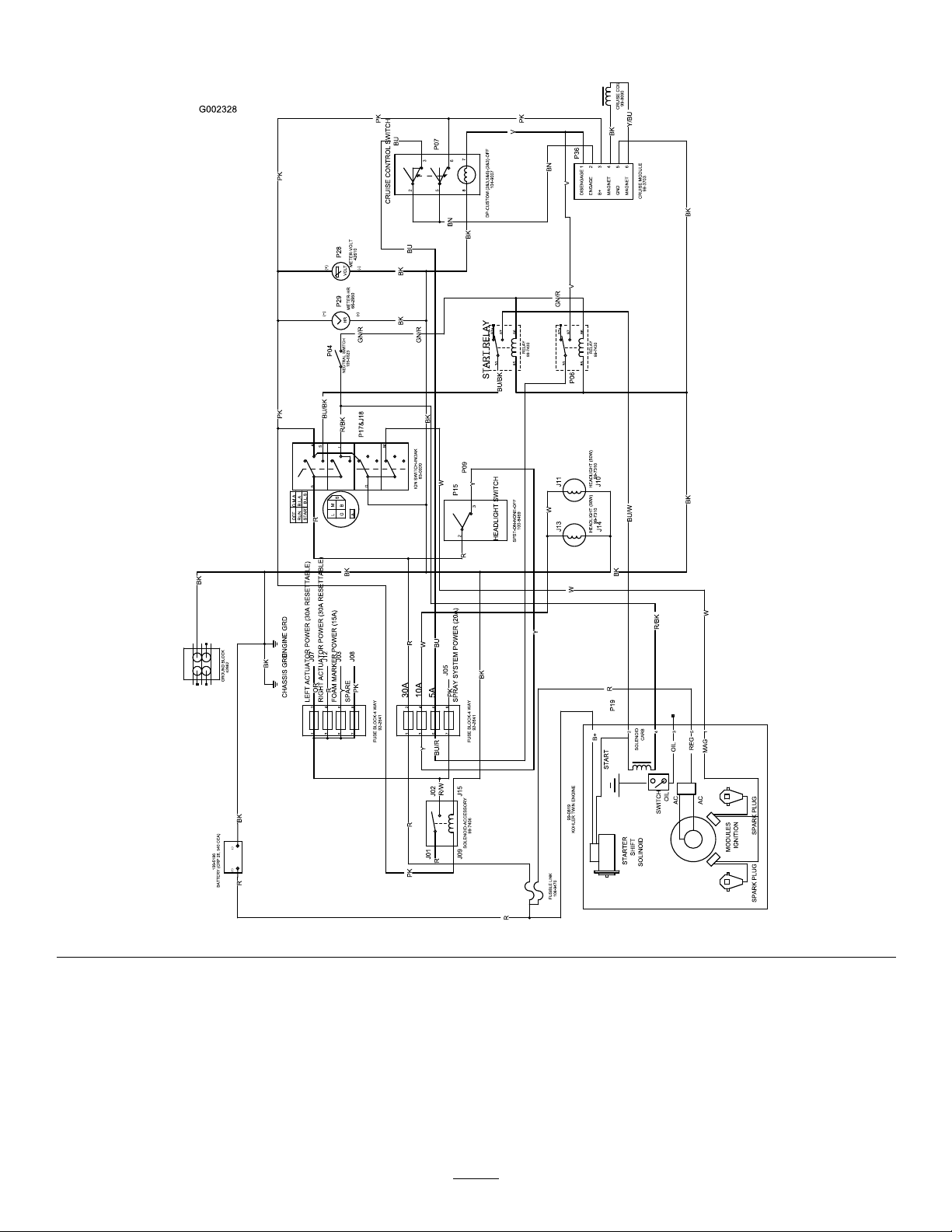
Schematics
Electrical,vehicle(Rev.B)
65
Page 66
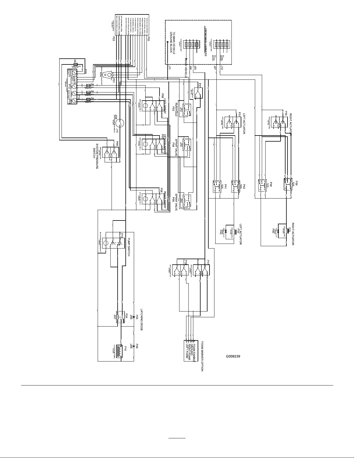
Electrical,spraysystem(Rev.A)
66
Page 67
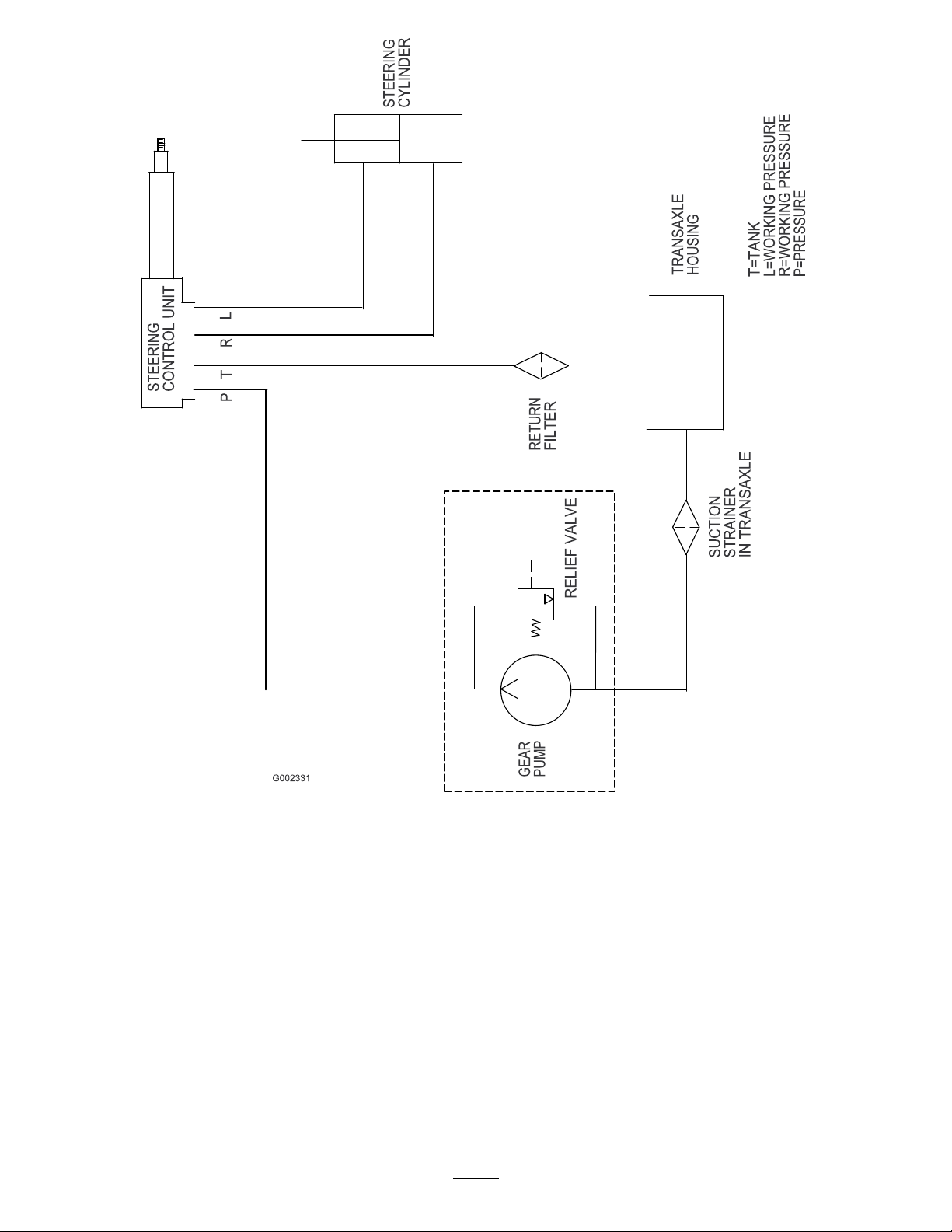
Hydraulic(Rev.A)
67
Page 68
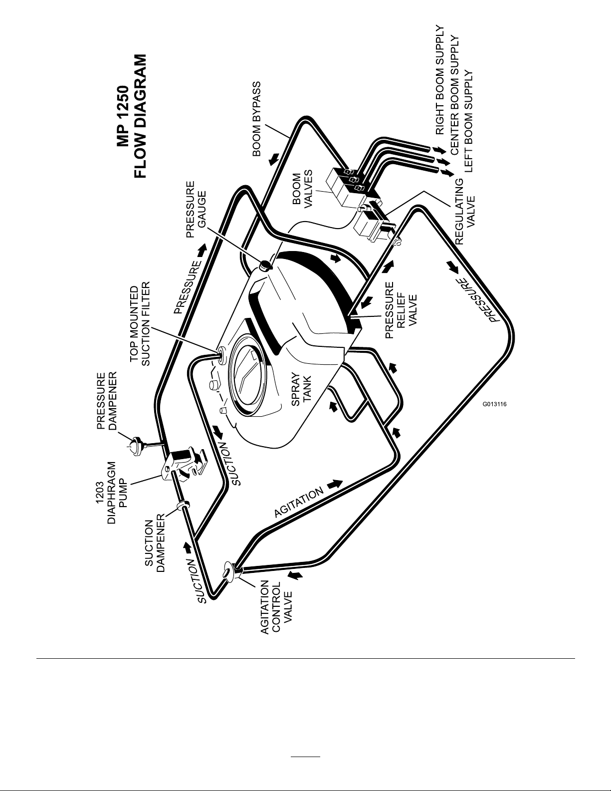
G0131 16
PRESSURE
PRESSURE
RELIEF
VALVE
REGULATING
VALVE
LEFT
BOOM SUPPL Y
CENTER BOOM SUPPL Y
RIGHT BOOM SUPPL Y
BOOM
VALVES
BOOM BYPASS
PRESSURE
GAUGE
PRESSURE
TOP MOUNTED
SUCTION FILTER
PRESSURE
DAMPENER
1203
DIAPHRAGM
PUMP
SUCTION
DAMPENER
SUCTION
SUCTION
AGITATION
CONTROL
VALVE
SPRA Y
TANK
AGITATION
MP 1250
FLOW DIAGRAM
FlowDiagram(Rev.A)
68
Page 69

Notes:
69
Page 70

Notes:
70
Page 71

Notes:
71
Page 72

TheT oroTotalCoverageGuarantee
ALimitedWarranty
ConditionsandProductsCovered
TheT oro
toanagreementbetweenthem,jointlywarrantyourT oroCommercial
product(“Product”)tobefreefromdefectsinmaterialsorworkmanship
fortwoyearsor1500operationalhours*,whicheveroccursrst.This
warrantyisapplicabletoallproductswiththeexceptionofAerators
(refertoseparatewarrantystatementsfortheseproducts).Wherea
warrantableconditionexists,wewillrepairtheProductatnocosttoyou
includingdiagnostics,labor ,parts,andtransportation.Thiswarranty
beginsonthedatetheProductisdeliveredtotheoriginalretailpurchaser.
*Productequippedwithanhourmeter.
®
Companyanditsafliate,T oroWarrantyCompany,pursuant
InstructionsforObtainingWarrantyService
YouareresponsiblefornotifyingtheCommercialProductsDistributoror
AuthorizedCommercialProductsDealerfromwhomyoupurchasedthe
Productassoonasyoubelieveawarrantableconditionexists.Ifyouneed
helplocatingaCommercialProductsDistributororAuthorizedDealer,or
ifyouhavequestionsregardingyourwarrantyrightsorresponsibilities,
youmaycontactusat:
CommercialProductsServiceDepartment
ToroWarrantyCompany
811 1L yndaleAvenueSouth
Bloomington,MN55420-1 196
E-mail:[email protected]
OwnerResponsibilities
AstheProductowner,youareresponsibleforrequiredmaintenance
andadjustmentsstatedinyourOperator’sManual.Failuretoperform
requiredmaintenanceandadjustmentscanbegroundsfordisallowinga
warrantyclaim.
ItemsandConditionsNotCovered
Notallproductfailuresormalfunctionsthatoccurduringthewarranty
periodaredefectsinmaterialsorworkmanship.Thiswarrantydoesnot
coverthefollowing:
•Productfailureswhichresultfromtheuseofnon-T ororeplacement
parts,orfrominstallationanduseofadd-on,ormodiednon-Toro
brandedaccessoriesandproducts.Aseparatewarrantymaybe
providedbythemanufactureroftheseitems.
•Productfailureswhichresultfromfailuretoperformrecommended
maintenanceand/oradjustments.Failuretoproperlymaintainyour
ToroproductpertheRecommendedMaintenancelistedinthe
Operator’sManualcanresultinclaimsforwarrantybeingdenied.
•ProductfailureswhichresultfromoperatingtheProductinan
abusive,negligentorrecklessmanner.
•Partssubjecttoconsumptionthroughuseunlessfoundtobe
defective.Examplesofpartswhichareconsumed,orusedup,during
normalProductoperationinclude,butarenotlimitedto,brakes
padsandlinings,clutchlinings,blades,reels,bedknives,tines,
sparkplugs,castorwheels,tires,lters,belts,andcertainsprayer
componentssuchasdiaphragms,nozzles,andcheckvalves,etc.
•Failurescausedbyoutsideinuence.Itemsconsideredtobeoutside
inuenceinclude,butarenotlimitedto,weather ,storagepractices,
contamination,useofunapprovedcoolants,lubricants,additives,
fertilizers,water,orchemicals,etc.
•Normalnoise,vibration,wearandtear,anddeterioration.
•Normal“wearandtear”includes,butisnotlimitedto,damageto
seatsduetowearorabrasion,wornpaintedsurfaces,scratched
decalsorwindows,etc.
Parts
Partsscheduledforreplacementasrequiredmaintenancearewarranted
fortheperiodoftimeuptothescheduledreplacementtimeforthatpart.
Partsreplacedunderthiswarrantyarecoveredforthedurationofthe
originalproductwarrantyandbecomethepropertyofT oro.T orowill
makethenaldecisionwhethertorepairanyexistingpartorassemblyor
replaceit.T oromayuseremanufacturedpartsforwarrantyrepairs.
NoteRegardingDeepCycleBatteryWarranty:
Deepcyclebatterieshaveaspeciedtotalnumberofkilowatt-hoursthey
candeliverduringtheirlifetime.Operating,recharging,andmaintenance
techniquescanextendorreducetotalbatterylife.Asthebatteriesinthis
productareconsumed,theamountofusefulworkbetweencharging
intervalswillslowlydecreaseuntilthebatteryiscompletelywornout.
Replacementofwornoutbatteries,duetonormalconsumption,isthe
responsibilityoftheproductowner.Batteryreplacementmayberequired
duringthenormalproductwarrantyperiodatowner’sexpense.
MaintenanceisatOwner’sExpense
Enginetune-up,lubricationcleaningandpolishing,replacementof
ItemsandConditionsNotCoveredlters,coolant,andcompleting
RecommendedMaintenancearesomeofthenormalservicesT oro
productsrequirethatareattheowner’sexpense.
GeneralConditions
RepairbyanAuthorizedT oroDistributororDealerisyoursoleremedy
underthiswarranty .
NeitherTheT oroCompanynorT oroWarrantyCompanyisliablefor
indirect,incidentalorconsequentialdamagesinconnectionwiththe
useoftheT oroProductscoveredbythiswarranty,includingany
costorexpenseofprovidingsubstituteequipmentorserviceduring
reasonableperiodsofmalfunctionornon-usependingcompletion
ofrepairsunderthiswarranty.ExceptfortheEmissionswarranty
referencedbelow,ifapplicable,thereisnootherexpresswarranty.
Allimpliedwarrantiesofmerchantabilityandtnessforusearelimitedto
thedurationofthisexpresswarranty .Somestatesdonotallowexclusions
ofincidentalorconsequentialdamages,orlimitationsonhowlongan
impliedwarrantylasts,sotheaboveexclusionsandlimitationsmaynot
applytoyou.
Thiswarrantygivesyouspeciclegalrights,andyoumayalsohaveother
rightswhichvaryfromstatetostate.
Noteregardingenginewarranty:
TheEmissionsControlSystemonyourProductmaybecoveredby
aseparatewarrantymeetingrequirementsestablishedbytheU.S.
EnvironmentalProtectionAgency(EP A)and/ortheCaliforniaAir
ResourcesBoard(CARB).Thehourlimitationssetforthabovedonot
applytotheEmissionsControlSystemWarranty .RefertotheEngine
EmissionControlWarrantyStatementprintedinyourOperator’sManual
orcontainedintheenginemanufacturer’sdocumentationfordetails
CountriesOtherthantheUnitedStatesorCanada
CustomerswhohavepurchasedT oroproductsexportedfromtheUnitedStatesorCanadashouldcontacttheirT oroDistributor(Dealer)toobtain
guaranteepoliciesforyourcountry ,province,orstate.IfforanyreasonyouaredissatisedwithyourDistributor’sserviceorhavedifcultyobtaining
guaranteeinformation,contacttheToroimporter .Ifallotherremediesfail,youmaycontactusatT oroWarrantyCompany.
374-0253RevA
 Loading...