


FormNo.3393-823RevE
MultiPro
ModelNo.41188—SerialNo.315000001andUp
®
1750TurfSprayer
Registeratwww.T oro.com.
OriginalInstructions(EN)
*3393-823*E
TheMultiProturfsprayerisadedicatedturfspray
applicationvehicleandisintendedtobeused
byprofessional,hiredoperatorsincommercial
applications.Itisprimarilydesignedforsprayingon
well-maintainedlawnsinparks,golfcourses,sports
elds,andoncommercialgrounds.
ThisproductcomplieswithallrelevantEuropean
directives;fordetails,pleaseseetheseparateproduct
specicDeclarationofConformity(DOC)sheet.
Important:Thisengineisnotequippedwith
asparkarrestermufer.Itisaviolationof
CaliforniaPublicResourceCodeSection4442to
useoroperatetheengineonanyforest-covered,
brush-covered,orgrass-coveredland.Other
statesorfederalareasmayhavesimilarlaws.
ThissparkignitionsystemcomplieswithCanadian
ICES-002.
TheenclosedEngineOwner'sManualis
suppliedforinformationregardingtheUS
EnvironmentalProtectionAgency(EPA)and
theCaliforniaEmissionControlRegulationof
emissionsystems,maintenance,andwarranty.
Replacementsmaybeorderedthroughtheengine
manufacturer.
Introduction
Readthismanualcarefullytolearnhowtooperate
andmaintainyourproductproperly.Theinformation
inthismanualcanhelpyouandothersavoidinjury
andproductdamage.AlthoughT orodesignsand
producessafeproducts,youareresponsiblefor
operatingtheproductproperlyandsafely .
YoumaycontactTorodirectlyatwww.Toro.com
forproductsafetyandoperationtrainingmaterials,
accessoryinformation,helpndingadealer,orto
registeryourproduct.
Wheneveryouneedservice,genuineToroparts,or
additionalinformation,contactanAuthorizedService
DealerorToroCustomerServiceandhavethemodel
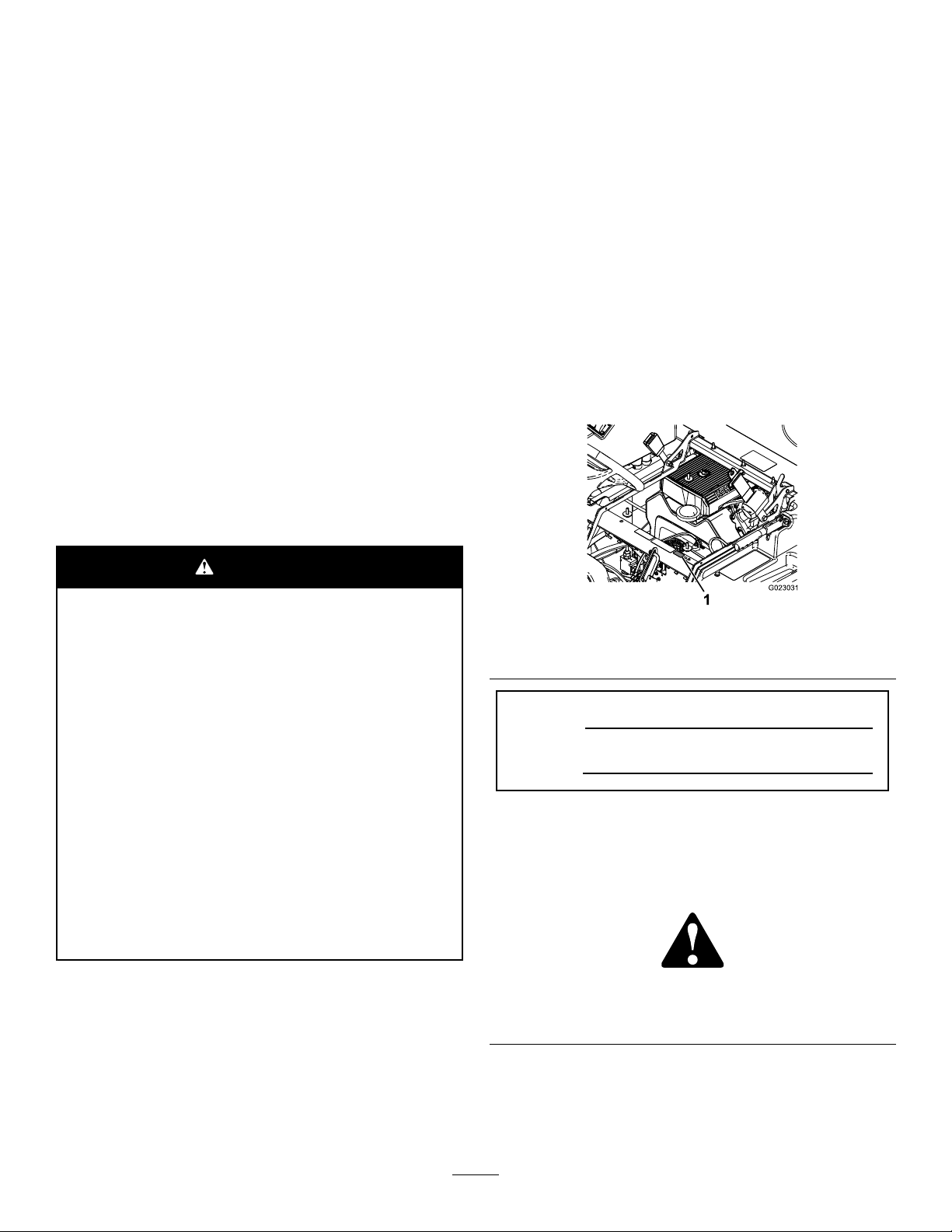
andserialnumbersofyourproductready.Figure1
illustratesthelocationofthemodelandserialnumbers
ontheproduct.
WARNING
CALIFORNIA
Proposition65Warning
Theengineexhaustfromthisproduct
containschemicalsknowntotheStateof
Californiatocausecancer,birthdefects,
orotherreproductiveharm.
Batteryposts,terminals,andrelated
accessoriescontainleadandlead
compounds,chemicalsknownto
theStateofCaliforniatocause
cancerandreproductiveharm.Wash
handsafterhandling.
Useofthisproductmaycauseexposure
tochemicalsknowntotheStateof
Californiatocausecancer,birthdefects,
orotherreproductiveharm.
g023031
Figure1
1.Locationofthemodelandserialnumbers
ModelNo.
SerialNo.
Thismanualidentiespotentialhazardsandhas
safetymessagesidentiedbythesafetyalertsymbol
(Figure2),whichsignalsahazardthatmaycause
seriousinjuryordeathifyoudonotfollowthe
recommendedprecautions.
g000502
Figure2
1.Safetyalertsymbol.
©2019—TheToro®Company
8111LyndaleAvenueSouth
Bloomington,MN55420
Thismanualuses2wordstohighlightinformation.
Importantcallsattentiontospecialmechanical
informationandNoteemphasizesgeneralinformation
worthyofspecialattention.
2
Contactusatwww.Toro.com.
PrintedintheUSA.
AllRightsReserved

Contents
Safety.......................................................................4
SafeOperatingPractices....................................4
ChemicalSafety.................................................5
WhileOperating..................................................6
Maintenance.......................................................7
SoundPower......................................................8
SoundPressure..................................................8
Hand-ArmVibration............................................8
WholeBodyVibration.........................................8
SafetyandInstructionalDecals..........................9
Setup......................................................................15
1InstallingtheAnti-siphonFill
Receptacle....................................................15
2CheckingtheBoomHingeSprings.................15
3LearningMoreaboutYourProduct.................16
ProductOverview...................................................17
Controls...........................................................19
Specications..................................................22
Attachments/Accessories.................................22
Operation................................................................23
SafetyFirst.......................................................23
PreparingtoDrivetheSprayerfortheFirst
Time..............................................................23
PerformingthePre-StartingChecks.................24
DrivingtheSprayer...........................................25
BreakinginaNewSprayer...............................25
AdjustingtheBoomstoLevel............................26
OperatingtheSprayer......................................27
FillingtheFreshWaterTank..............................27
FillingtheSprayTank........................................27
OperatingtheBooms........................................28
Spraying...........................................................28
SprayingTips....................................................28
CleaningtheSprayer........................................29
UsingtheInfoCenterLCDDisplay....................30
CalibratingtheSprayerFlow.............................32
CalibratingtheSprayerSpeed..........................33
CalibratingtheBoom-SectionBypass
Valves...........................................................33
AgitationBypassValveKnobPosition...............34
CalibratingtheAgitationBypassValve..............34
AdjustingtheMasterBoomBypass
Valve.............................................................35
LocatingthePump............................................35
TowingtheSprayer...........................................35
TransportingtheSprayer..................................35
Maintenance...........................................................36
RecommendedMaintenanceSchedule(s)...........36
DailyMaintenanceChecklist.............................37
NotationforAreasofConcern...........................38
Pre-MaintenanceProcedures..............................39
JackingUptheSprayer.....................................39
Lubrication..........................................................39
GreasingtheSprayer........................................39
GreasingtheBoomHinges...............................39
EngineMaintenance...........................................40
CheckingtheAirIntakeScreen.........................40
ServicingtheAirCleaner..................................40
ServicingtheEngineOil....................................41
ChangingtheSparkPlugs................................43
FuelSystemMaintenance...................................44
ReplacingtheFuelFilter...................................44
DrainingtheFuelT ank......................................44
ElectricalSystemMaintenance...........................45
LocatingtheFuses...........................................45
ServicingtheBattery.........................................45
DriveSystemMaintenance..................................47
InspectingtheWheelsandTires.......................47
AdjustingtheFrontWheelToe-in......................47
BrakeMaintenance.............................................48
CheckingtheBrakeFluid..................................48
InspectingtheBrakes.......................................48
AdjustingtheParkingBrake..............................48
HydraulicSystemMaintenance...........................49
CheckingtheTransaxle/Hydraulic
Fluid..............................................................49
ChangingTransaxle/HydraulicFluid.................49
ReplacingtheHydraulicFilter..........................50
SpraySystemMaintenance.................................50
InspectingtheHoses........................................50
ChangingthePressureFilter............................51
InspectingthePump.........................................51
InspectingtheNylonPivotBushings.................51
SprayerFlowDiagram......................................53
Cleaning..............................................................54
CleaningtheFlowmeter....................................54
CleaningtheSuctionStrainer...........................54
CleaningtheSprayerV alves.............................55
Storage...................................................................64
Troubleshooting......................................................66
3

Safety
equipment,operatorcontrols,andsafetysigns.
•Becomefamiliarwiththesafeoperationofthe
Improperuseormaintenancebytheoperatoror
ownercanresultininjury.Toreducethepotential
forinjury,complywiththesesafetyinstructionsand
alwayspayattentiontothesafetyalertsymbol,which
meansCaution,Warning,orDanger—“personalsafety
instruction.”Failuretocomplywiththeinstructionmay
resultinpersonalinjuryordeath.
ThemachinemeetstherequirementsofSAEJ2258.
SafeOperatingPractices
Important:Themachineisdesignedprimarily
asanoff-roadvehicleandisnotintendedfor
extensiveuseonpublicroads.Whenusing
themachineonpublicroads,followalltrafc
regulationsanduseanyadditionalaccessories
thatmayberequiredbylaw,suchaslights,turn
signals,slowmovingvehicle(SMV)sign,and
othersasrequired.
TheMulti-Pro1750TurfSprayerwasdesigned
andtestedtooffersafeservicewhenoperatedand
maintainedproperly.Althoughhazardcontroland
accidentpreventionpartiallyaredependentuponthe
designandcongurationofthemachine,thesefactors
arealsodependentupontheawareness,concern,
andpropertrainingofthepersonnelinvolvedinthe
operation,maintenanceandstorageofthemachine.
Improperuseormaintenanceofthemachinecan
resultininjuryordeath.
NotalloftheattachmentsthatadapttotheMulti-Pro
1750TurfSprayerarecoveredinthismanual.See
thespecicOperator’sManualprovidedwitheach
attachmentforadditionalsafetyinstructions.Read
thesemanuals.
Toreducethepotentialforinjuryordeath,complywith
thefollowingsafetyinstructions:
Supervisor'sResponsibilities
•Makesurethatoperatorsarethoroughlytrained
andfamiliarwiththeOperator'sManual,Engine
Manual,andalllabelsonthesprayer.
•Establishyourownspecialproceduresandwork
rulesforunusualoperatingconditions(e.g.slopes
toosteepforsprayeroperation).
Training
•ReadtheOperator'sManualandothertraining
materialbeforeoperatingthemachine.
•Alloperatorsandmechanicsshouldbetrained.
Theownerisresponsiblefortrainingtheusers.
•Neverallowuntrainedpeopletooperateorservice
theequipment.
Note:Localregulationsmayrestricttheageof
theoperator.
•Theowner/usercanpreventandisresponsible
foraccidentsorinjuriesoccurringtohimselfor
herself,otherpeople,ordamagetoproperty.
BeforeOperating
•Operatethemachineonlyafterreadingand
understandingthecontentsofthismanual.
•Neverallowchildrentooperatethesprayer.
•Neverallowotheradultstooperatethesprayer
withoutrstreadingandunderstandingthe
Operator'sManual.Onlytrainedandauthorized
personsshouldoperatethissprayer.Makesure
thatalloperatorsarephysicallyandmentally
capableofoperatingthesprayer.
•Thissprayerisdesignedtocarryonlyyou,the
operator.Nevercarryanypassengersonthe
sprayer.
•Neveroperatethesprayerwhenunderthe
inuenceofdrugsoralcohol.Evenprescription
drugsandcoldmedicinescancausedrowsiness.
•Donotdrivethesprayerwhenyouaretired.Be
suretotakeoccasionalbreaks.Itisveryimportant
thatyoustayalertatalltimes.
•Becomefamiliarwiththecontrolsandknowhow
tostoptheenginequickly .
•Keepallshields,safetydevices,anddecals
inplace.Ifashield,safetydevice,ordecalis
malfunctioning,illegible,ordamaged,repairor
replaceitbeforeoperatingthemachine.
•Wearappropriateclothing;includingahardhat,
safetyglasses,longpants,safetyshoes,rubber
boots,gloves,andhearingprotection.Donotwear
loosettingclothingorjewelrywhichcouldget
caughtinmovingpartsandcausepersonalinjury.
Note:Wearingsafetyglasses,safetyshoes,long
pants,andahelmetisadvisableandrequiredby
somelocalsafetyandinsuranceregulations.
Note:Iftheoperator(s)ormechanic(s)cannot
readthemanuallanguage,itistheowner's
responsibilitytoexplainthismaterialtothem.
4

CAUTION
Thismachineproducessoundlevelsin
excessof85dBAattheoperator’searand
cancausehearinglossthroughextended
periodsofexposure.
Wearhearingprotectionwhenoperating
thismachine.
ChemicalSafety
WARNING
•Chemicalsubstancesusedinthesprayer
systemmaybehazardousandtoxicto
you,bystanders,animals,plants,soilsor
otherproperty.
•Avoiddrivingwhenitisdark,especiallyin
unfamiliarareas.Ifyoumustdrivewhenitisdark,
besuretodrivecautiously ,usetheheadlights,and
evenconsideraddingadditionallights.
•Beextremelycarefulwhenoperatingaround
people.Alwaysbeawareofwherebystanders
mightbeandkeepthemawayfromtheworkarea.
•Beforeoperatingthesprayer,alwayscheckthe
designatedareasofthesprayerthatarestatedin
thePre-StartingChecksintheOperationsection.
Ifthemachinedoesnotfunctioncorrectlyoris
damagedinanyway ,donotusethesprayer.
Makesurethattheproblemiscorrectedbeforethe
sprayerorattachmentisoperated.
•Makesuretheoperator’sareaiscleanandfree
fromchemicalresidueanddebrisbuildup.
•Ensurethatalluidlineconnectorsaretightand
allhosesareingoodconditionbeforeapplying
pressuretothesystem.
•Sincefuelishighlyammable,handleitcarefully.
–Useanapprovedfuelcontainer.
–Donotremovethecapfromthefueltankwhen
theengineishotorrunning.Allowtheengine
tocoolbeforefuelingthemachine.
–Donotsmokewhilehandlinggasoline.
–Fillthefueltankofthemachineoutdoors.
–Fillthefueltankofthemachinetoabout25mm
(1inch)belowthetopofthetank(thebottom
ofthellerneck).Donotoverllthefueltank.
–Wipeupanyspilledfuel.
•Carefullyreadandfollowthechemical
warninglabelsandMaterialSafetyData
Sheets(MSDS)forallchemicalsusedand
protectyourselfaccordingtothechemical
manufacturer'srecommendations.Ensure
thataslittleskinaspossibleisexposed
whileusingchemicals.Useappropriate
PersonalProtectiveEquipment(PPE)
toguardagainstpersonalcontactwith
chemicals,suchas:
–safetyglasses,goggles,and/orface
shield
–respiratororltermask
–chemicalresistantgloves
–rubberbootsorothersubstantial
footwear
–hearingprotection
–cleanchangeofclothes,soap,and
disposabletowels,tobekepton-hand,
intheeventofachemicalspill.
Important:Keepinmindthattheremaybemore
thanonechemicalused,andinformationoneach
chemicalshouldbeassessed.
Refusetooperateorworkonthesprayerifthis
informationisnotavailable!
Beforeworkingonasprayersystem,make
surethatthesystemhasbeentriplerinsedand
neutralizedaccordingtotherecommendationsof
thechemicalmanufacturer(s)andallofthevalves
havebeencycled3times.
Verifythereisanadequatesupplyofcleanwater
andsoapnearby,andimmediatelywashoffany
chemicalsthatcontactyou.
•Obtainpropertrainingbeforeusingorhandling
chemicals.
•Usethecorrectchemicalforthejob.
•Followthechemicalmanufacturer'sinstructionsfor
thesafeapplicationofthechemical.Donotexceed
recommendedsystemapplicationpressure.
•Donotll,calibrate,orcleantheunitwhenpeople,
especiallychildren,orpetsareinthearea.
•Handlechemicalsinawellventilatedarea.
5

•Havecleanwateravailableespeciallywhenlling
thespraytank.
•Donoteat,drink,orsmokewhileworkingwith
chemicals.
•Donotcleanspraynozzlesbyblowingthrough
themorplacinginmouth.
•Alwayswashyourhandsandotherexposedareas
assoonaspossibleafteryounishworkingwith
chemicals.
•Keepchemicalsintheiroriginalpackagesand
storedinasafelocation.
•Properlydisposeofunusedchemicalsand
chemicalcontainersasinstructedbythechemical
manufacturerandyourlocalcodes.
•Chemicalsandfumesaredangerous;neverenter
thetankorplaceyourheadoverorintheopening
ofatank.
•Followalllocal,state,andfederalregulationsfor
spreadingorsprayingchemicals.
WhileOperating
WARNING
Engineexhaustcontainscarbonmonoxide,
whichisanodorless,deadlypoisonthatcan
killyou.
Donotrunengineindoorsorinanenclosed
area.
•Theoperatorshouldremainseatedwhenever
thesprayerisinmotion.Theoperatorshould
keepbothhandsonthesteeringwheelwhenever
possible.Keepyourarmsandlegswithinthe
sprayerbodyatalltimes.
•Failuretooperatethesprayersafelymayresultin
anaccident,tipoverofthesprayer,andserious
injuryordeath.Drivecarefully.T opreventtipping
orlossofcontrol:
–Useextremecaution,reducespeed,and
maintainasafedistancearoundsandtraps,
ditches,creeks,ramps,unfamiliarareas,or
anyareasthathaveabruptchangesinground
conditionsorelevation.
–Watchforholesorotherhiddenhazards.
–Useextracautionwhenoperatingthesprayer
onwetsurfaces,inadverseweatherconditions,
athigherspeeds,orwithafullload.Stopping
timeanddistancewillincreasewithafullload.
–Avoidsuddenstopsandstarts.Donotgo
fromreversetoforwardorforwardtoreverse
withoutrstcomingtoacompletestop.
–Slowdownbeforeturning.Donotattempt
sharpturnsorabruptmaneuversorother
unsafedrivingactionsthatmaycausealoss
ofsprayercontrol.
–Beforebackingup,looktotherearandensure
thatnooneisbehindyou.Backupslowly.
–Watchoutfortrafcwhenyouarenearor
crossingroads.Alwaysyieldtherightofwayto
pedestriansandothervehicles.Thissprayeris
notdesignedforuseonstreetsorhighways.
Alwayssignalyourturnsorstopearlyenough
sothatotherpeopleknowwhatyouplantodo.
Obeyalltrafcrulesandregulations.
–Theelectricalandexhaustsystemsofthe
sprayercanproducesparkscapableofigniting
explosivematerials.Neveroperatethesprayer
inornearanareawherethereisdustorfumes
intheairwhichareexplosive.
–Ifyouareeverunsureaboutsafeoperation,
stopworkandaskyoursupervisor.
•Donottouchtheengineormuferwhiletheengine
isrunningorsoonafterithasstopped.These
areasmaybehotenoughtocauseburns.
•Ifthemachineevervibratesabnormally ,stop
immediately,waitforallmotiontostop,andinspect
thesprayerfordamage.Repairalldamagebefore
resumingoperation.
•Beforegettingoffoftheseat:
1.Stopthemovementofthemachine.
2.PlacetherangeselectorinNeutralandset
theparkingbrake.
3.TurntheignitionkeytoOff.
4.Removetheignitionkey .
Important:Donotparkthemachineon
anincline.
•Lightningcancausesevereinjuryordeath.If
lightningisseenorthunderisheardinthearea,do
notoperatethemachine;seekshelter.
Braking
•Slowdownbeforeyouapproachanobstacle.
Thisgivesyouextratimetostoporturnaway.
Hittinganobstaclecandamagethesprayerand
itscontents.Moreimportant,itcaninjureyou.
•GrossVehicleWeight(GVW)hasamajorimpact
onyourabilitytostopand/orturn.Heavyloadsand
attachmentsmakeasprayerhardertostoporturn.
Theheaviertheload,thelongerittakestostop.
•Turfandpavementaremuchmoreslipperywhen
theyarewet.Itcantake2to4timesaslongto
stoponwetsurfacesasondrysurfaces.Ifyou
drivethroughstandingwaterdeepenoughtoget
thebrakeswet,theywillnotworkwelluntiltheyare
dry.Afterdrivingthroughwater,youshouldtest
thebrakestomakesuretheyworkproperly .Ifthey
6

donot,driveslowlywhileputtinglightpressureon
thebrakepedal.Thiswilldrythebrakesout.
ROPSSafety
WARNING
Suddenchangesinterrainmaycause
abruptsteeringwheelmovement,possibly
resultinginhandandarminjuries.
Note:ForeachmachinecoveredinthisOperator’s
Manual,acabinstalledbyT oroisaROPS.
•DonotremovetheROPSfromthemachine.
•Fastentheseatbeltandensurethatyoucan
releaseitquicklyinanemergency.Alwayswear
yourseatbeltwhentherollbarisuporona
machinewithacabinstalledbyToro.
•Checkcarefullyforoverheadobstructionsanddo
notcontactthem.
•KeeptheROPSinsafeoperatingconditionby
thoroughlyinspectingitperiodicallyfordamage
andkeepingallthemountingfastenerstight.
•ReplaceanydamagedROPScomponent.Donot
repairoralterit.
OperatingonHillsandRough
Terrain
Operatingthesprayeronahillmaycausetippingor
rollingofthesprayer,ortheenginemaystallandyou
couldloseheadwayonthehill.Thiscouldresultin
personalinjury.
•Donotacceleratequicklyorslamonthebrakes
whenbackingdownahill,especiallywithaload.
•Neverdriveacrossasteephill;alwaysdrive
straightupordownorgoaroundthehill.
•Reduceyourspeedwhenoperatingonrough
terrainandnearcurbs.
•Gripthesteeringwheellooselyaroundthe
perimeter.Keepyourhandsclearofthesteering
wheelspokes.
Loading
Theweightofthecargocanchangethesprayer
centerofgravityandsprayerhandling.T oavoidloss
ofcontrolandpersonalinjury,followtheseguidelines:
•Reducetheweightoftheloadwhenoperating
onhillsandroughterraintoavoidtippingor
overturningofthesprayer.
•Liquidloadscanshift.Thisshiftinghappens
mostoftenwhileturning,goingupordownhills,
suddenlychangingspeeds,orwhiledrivingover
roughsurfaces.Shiftingloadscancausethe
sprayertotipover.
•Whenoperatingwithaheavyload,reduceyour
speedandallowforsufcientbrakingdistance.Do
notsuddenlyapplythebrakes.Useextracaution
onslopes.
•Beawarethatheavyloadsincreaseyourstopping
distanceandreduceyourabilitytoturnquickly
withouttippingover.
•Iftheenginestallsoryoubegintoloseheadway
whileclimbingahill,graduallyapplythebrakes
andslowlybackstraightdownthehill.
•Turningwhiletravelingupordownhillscanbe
dangerous.Ifyouhavetoturnwhileonahill,doit
slowlyandcautiously.Nevermakesharporfast
turns.
•Heavyloadsaffectstability.Reducetheweightof
theloadandyourspeedwhenoperatingonhills.
•Avoidstoppingonhills,especiallywithaload.
Stoppingwhilegoingdownahillwilltakelonger
thanstoppingonlevelground.Ifthesprayermust
bestopped,avoidsuddenspeedchanges,which
mayinitiatetippingorrollingofthesprayer.Donot
slamonthebrakeswhenrollingbackward,asthis
maycausethesprayertooverturn.
•Reducespeedandloadwhenoperatingonrough
terrain,unevenground,andnearcurbs,holes,and
othersuddenchangesinterrain.Loadsmayshift,
causingthesprayertobecomeunstable.
Maintenance
•Onlypermitqualiedandauthorizedpersonnelto
maintain,repair,adjust,orinspectthesprayer.
•Beforeservicingormakingadjustmentstothe
machine,stoptheengine,settheparkingbrake,
andremovethekeyfromtheignitiontoprevent
someonefromaccidentallystartingtheengine.
•Tomakesurethattheentiremachineisingood
condition,keepallnuts,bolts,andscrewsproperly
tightened.
•Toreducethepotentialforre,keeptheengine
areafreeofexcessivegrease,grass,leaves,and
accumulationofdirt.
•Neveruseanopenametocheckthelevelor
leakageoffuelorbatteryelectrolyte.
•Iftheenginemustberunningtoperforma
maintenanceadjustment,keepyourhands,feet,
clothing,andanypartsofyourbodyawayfrom
7

theengineandanymovingparts.Keepeveryone
away.
•Donotuseopenpansoffuelorammable
cleaninguidswhencleaningparts.
•Donotadjustthegroundspeedgovernor.To
ensuresafetyandaccuracy,haveanAuthorized
ToroDistributorcheckthegroundspeed.
•Keepyourbodyandhandsawayfrompinhole
leaksornozzlesthatejecthighpressureuid.Use
cardboardorpapertondleaks.Fluidescaping
underpressurecanpenetrateskinandcause
injuryrequiringsurgerywithinafewhoursbya
qualiedsurgeon;otherwise,gangrenemayresult.
•Ifmajorrepairsareeverneededorassistanceis
required,contactanAuthorizedToroDistributor.
•Tobesureofoptimumperformanceandsafety,
alwayspurchasegenuineT ororeplacement
partsandaccessories.Replacementpartsand
accessoriesmadebyothermanufacturerscould
bedangerous.Alteringthissprayerinanymanner
thatmayaffectsprayeroperation,performance,
durability,oritsuse,mayresultininjuryordeath.
Suchusecouldvoidtheproductwarranty.
WholeBodyVibration
Measuredvibrationlevel=0.58m/s
UncertaintyValue(K)=0.29m/s
Measuredvaluesweredeterminedaccordingtothe
proceduresoutlinedinEN1032.
2
2
SoundPower
Thisunithasaguaranteedsoundpowerlevelofof
98dBA,whichincludesanUncertaintyValue(K)of
1dBA.
Soundpowerlevelwasdeterminedaccordingtothe
proceduresoutlinedinISO1 1094.
SoundPressure
Thisunithasasoundpressurelevelattheoperator’s
earof86dBA,whichincludesanUncertaintyValue
(K)of1dBA.
Soundpressurelevelwasdeterminedaccordingto
theproceduresoutlinedinENISO1 1201.
Hand-ArmVibration
Measuredvibrationlevelforrighthand=3.00m/s
Measuredvibrationlevelforlefthand=3.20m/s
UncertaintyValue(K)=1.6m/s
2
2
2
Measuredvaluesweredeterminedaccordingtothe
proceduresoutlinedinENISO20643.
8
SafetyandInstructionalDecals
Safetydecalsandinstructionsareeasilyvisibletotheoperatorandarelocatednearanyarea
ofpotentialdanger.Replaceanydecalthatisdamagedorlost.
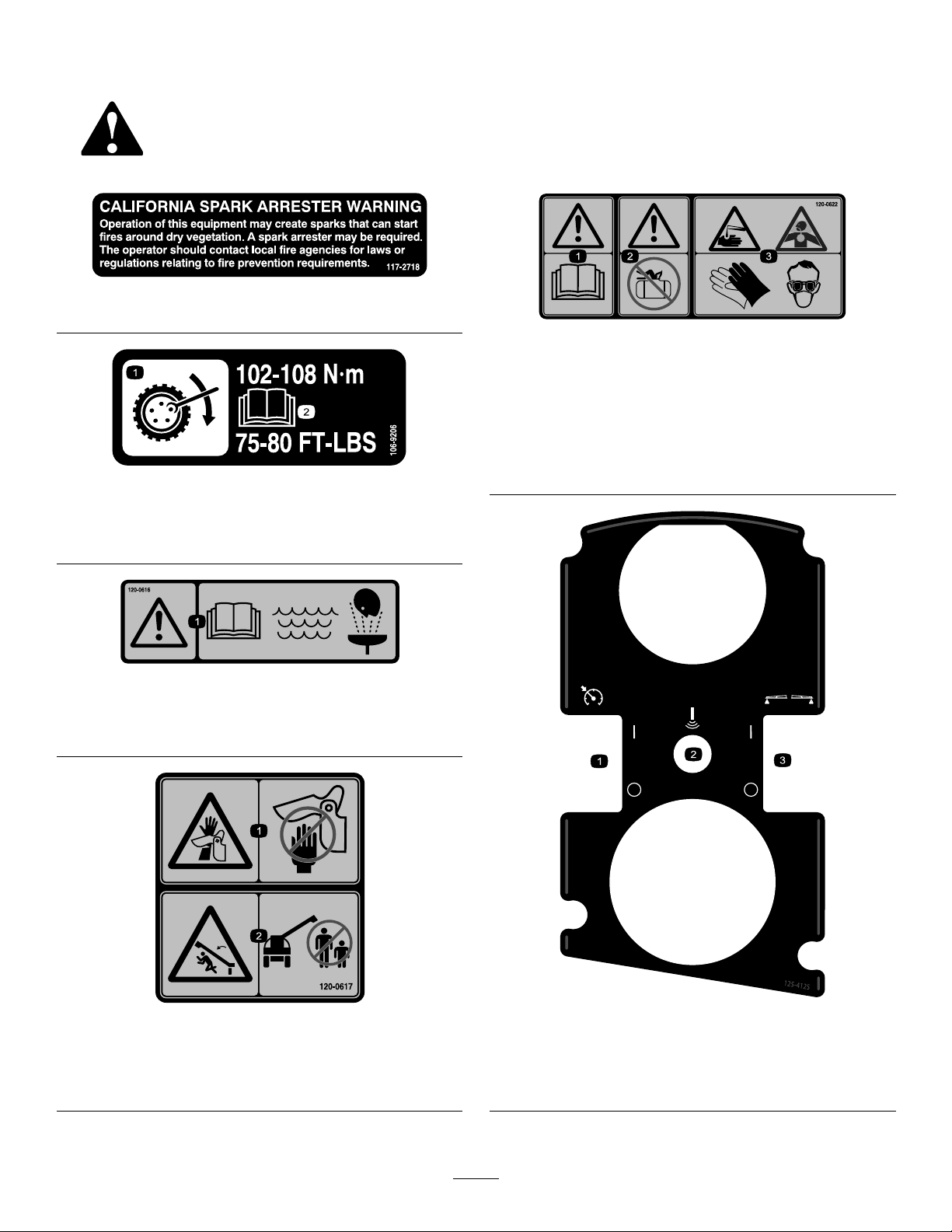
117–2718
decal117-2718
decal120-0622
120–0622
106-9206
1.Wheeltorquespecications
2.ReadtheOperator'sManual.
120–0616
1.Warning—readtheOperator’sManual;usefresh,clean
waterforrst-aidwashing.
1.Warning—readthe
Operator’sManual.
3.Chemicalburnhazard;
toxicgasinhalation
hazard—wearhandand
skinprotection;weareye
andrespiratoryprotection.
2.Warning—donotenterthe
decal106-9206
decal120-0616
sprayertank.
1.Severinghazardofhand,
pinchingpoint—keep
awayfromactuatedjoints.
decal120-0617
120–0617
2.Crushinghazard—keep
bystandersawayfromthe
machine.
1.Turnthethrottle
lock/speedlockon/off
2.Sonicboom(optional)
125–4125
3.Turnthefoammakers
on/off(optional)
decal125-4125
9

decal130-8293
130-8293
1.Sprayeroff
2.Sprayeron
5.Increasespeed
6.Decreasespeed
3.Engineon7.Agitationon
4.Engineoff8.Agitationoff
125–4128
1.Raise/lowerleftboom
2.Raise/lowerrightboom
3.Engine—start
4.Engine—run
5.Engine—stop
decal125-6694
125–6694
1.Tiedownlocation
decal125-4128
1.Leftboom
2.Centerboom
decal125-8113
125–8113
decal125-4129
125–4129
3.Rightboom
1.Gearselection5.Automatic(optional)
2.Lockdifferentiallock6.Manual(optional)
3.Unlockdifferentiallock
7.Rewindhosereel
4.Toggleheadlightson/off
(optional)
10
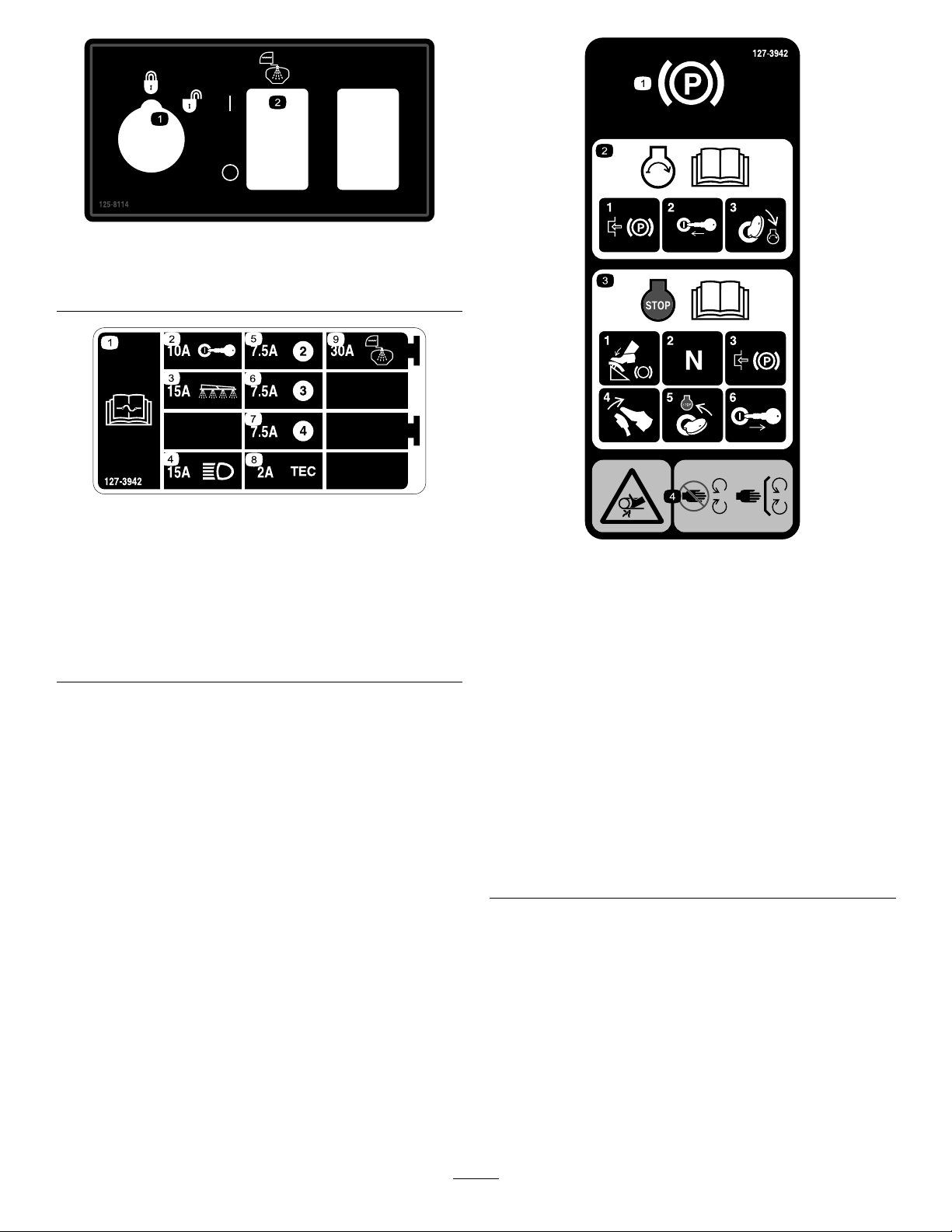
125–8114
decal125-8114
1.Ratelockout
locked/unlocked
127–3942
1.ReadtheOperator’s
Manualforinformationon
fuses.
2.10A—Ignition7.7.5A
3.15A—Sprayerboom8.2A—TEC
4.15A—Headlights
5.7.5A
2.Togglerinsepumpon/off
decal127-3942
6.7.5A
9.30A—Rinsetank
1.Parkingbrake
2.Forinformationonstarting
theengine,readthe
Operator’sManual—1)
Engagetheparkingbrake;
2)Insertthekeyintothe
ignition;3)Turnthekeyto
theenginerunposition.
decal127-3935
127–3935
3.Forinformationon
stoppingtheengine,read
theOperator’sManual—1)
Pressdownonthebrake
pedal;2)Setthegearto
neutral;3)Engagethe
parkingbrake;4)Release
thebrakepedal;5)Turn
theignitionkeytothe
enginestopposition;6)
Removethekeyfromthe
ignition.
4.Entanglementhazard,
belt—keepawayfrom
movingparts;keepall
guardsandshieldsin
place.
11

decal127-3937
127–3937
1.Warning—donotstep.3.Entanglementhazard,
belt—keepawayfrom
movingparts;keepall
guardsandshieldsin
place.
2.Warning—keepawayfrom
hotsurfaces.
1.Warning—readthe
Operator’sManual;always
wearaseatbeltwhen
operatingthemachine;do
nottipthemachine.
2.Fallinghazard—donot
carrypassengersonthe
sprayertank.
decal127-3939
127–3939
3.Cutting/dismemberment
hazard—keeparmsand
legsinsidethevehicleat
alltimes.
4.Warning—donotdrill,
weld,oraltertheROPS
system.
12

1.ReadtheOperator’sManual.
decal127-3938
127–3938
decal127-3941
127–3941
1.Warning—donotoperatethemachinewithoutpropertraining;
readtheOperator’sManual.
2.Warning—keepbystandersawaywhenoperatingthe
machine.
3.Warning—keepawayfrommovingparts;keepallguardsand
shieldsinplace.
4.Electricalshockhazard,overheadpowerlines—checkthe
areaforoverheadpowerlinesbeforeoperatingthemachine
inthearea.
5.Warning—Engagetheparkingbrake,stoptheengine,and
removethekeyfromtheignitionbeforeleavingthemachine.
6.Tippinghazard—Moveslowlywhenthesprayertankisfull;
moveslowlywhendrivingoverroughterrain;donotturnat
highspeed;turnslowly;driveslowlywhendrivingacrossor
upslopes.
13

127-6976
1.Decrease2.Increase
decal127-6976
decal127-6982
127-6982
127-6979
1.Bypass-returnow3.Agitationow
2.Flow
1.Bypass-returnow
decal127-6979
2.Boomspray
decal127-6984
127-6984
1.Flow
2.Tank-returnow
1.Bypass-returnow
2.Flow
decal127-6981
127-6981
3.Boomspray
14
Setup
Note:Determinetheleftandrightsidesofthe
machinefromthenormaloperatingposition.
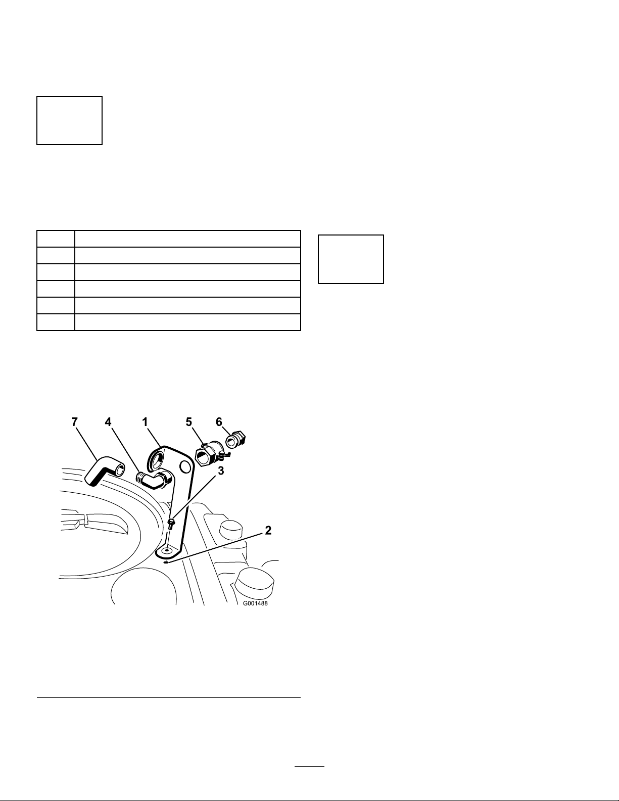
1
Note:Installthettingwiththeopenend
pointingtowardthelargeopeninginthebracket
andtowardthetankopeningsothewaterwill
arcintothetankwhenyoullit.
3.Installthehoseadapterintothequickcoupler
(Figure3).
4.Locktheadapterintoplacebyswingingthe
leverstowardtheadapterandthensecurethem
withthehairpincotters(Figure3).
InstallingtheAnti-siphon
FillReceptacle
Partsneededforthisprocedure:
1
90°tting
1
Quickcoupler
1Hoseadapter
1Fillreceptaclebracket
1
Flange-headbolt,5/16x3/4inch
1Anti-siphonhose
Procedure
1.Placethellreceptaclebracketoverthe
threadedholeinthetankandsecureitwitha
ange-headbolt(5/16x3/4inch)(Figure3).
5.Installtheanti-siphonhosethroughthelarge
openingonthebracketandontothebarbedend
ofthe90°elbowtting(Figure3).
Important:Donotlengthenthehoseto
allowcontactwiththetankuids.
2
CheckingtheBoomHinge
Springs
NoPartsRequired
Procedure
Important:Operatingthespraysystemwith
theboomhingespringsundertheincorrect
compressioncoulddamagetheboomassembly.
Measurethespringsandusethejamnutto
compressthespringsto4cm(1–1/2inches)if
necessary.
Figure3
1.Fillreceptaclebracket
2.Threadedholeinthetank6.Hoseadapter
3.Flangebolt,5/16x3/4inch
4.90°elbowtting
2.Placethethreadedendofthe90°elbowtting
throughthebracketandthreadthequickcoupler
ontoit,securingittothebracket(Figure3).
5.Quickcoupler
7.Anti-siphonhose
Thesprayerisshippedwiththeboomextensions
swungforwardtofacilitatepackagingofthemachine.
Thespringsarenotfullytightenedatthetimeof
manufacturetoallowtheboomstobeinthisposition
fortransit.Beforeoperatingthemachine,thesprings
mustbeadjustedtothecorrectcompression.
1.Ifnecessary,removethepackingcomponents
thatsecuretherightandleftextensionbooms
duringshipping.
g001488
2.Supporttheboomswhiletheyareextendedto
thesprayposition.
3.Attheboomhinge,measurethecompressionof
theupperandlowerspringswhilethebooms
areintheirextendedposition(Figure4).
A.Allspringsmustbecompresseduntilthey
measure4cm(1–1/2inches).
B.Usethejamnuttocompressanyspringthat
measuregreaterthan4cm(1–1/2inches).
15

Figure4
1.Boomhingespring2.Jamnut
4.Repeattheprocedureforeachspringonboth
boomhinges.
5.Movetheboomsintothetransport“X”position.
SeeUsingtheBoomTransportCradle(page28)
formoreinformation.
3
LearningMoreaboutYour
Product
Partsneededforthisprocedure:
1Ignitionkey
1
Operator'sManual
1
EngineOperator'sManual
1
PartsCatalog
1
Operatortrainingmaterial
g002332
1Registrationcard
1
Pre-deliveryInspectionSheet
Procedure
1.Readthemanuals.
2.Viewtheoperatortrainingmaterial.
3.Completetheregistrationcardandreturnitto
Toro.
4.Storethedocumentationinasafeplace.
16

ProductOverview
Figure5
1.ROPSbar4.Valvemanifolds
2.Anti-siphonreceptacle5.Rightboom8.Agitationthrottlevalve11.Fueltank
3.Chemicaltanklid6.Centerboom9.Pressurelter
7.Boomcontrolcylinder
17
10.Leftboom
12.Parkingbrake
g028639

Figure6
1.Rightboom4.Freshwatertank
2.Boomtransportcradle
3.Leftboom
5.Operator’sseat
g028072
18
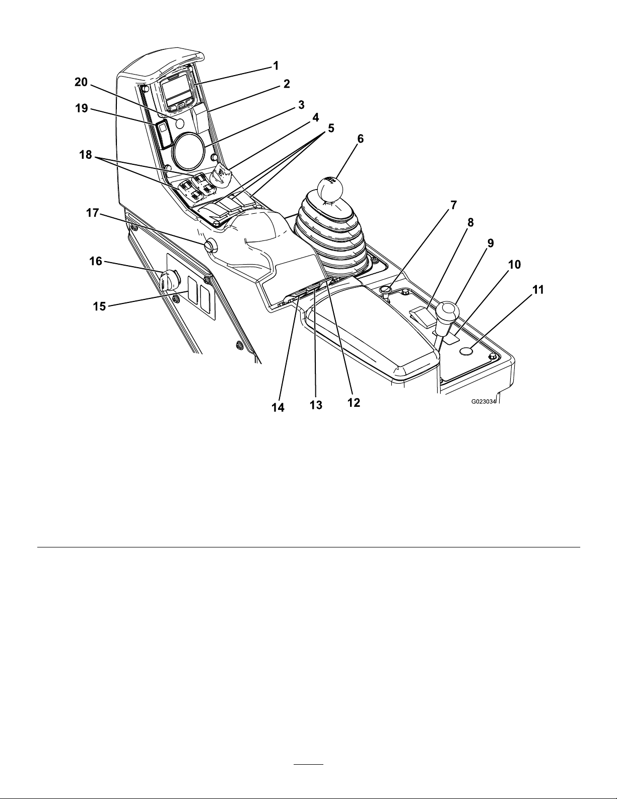
Controls
1.InfoCenter
2.Foammarkerswitch
(optional)
3.Pressuregauge8.Headlightswitch
4.Engineswitch
5.Boom-Sectionswitches10.Sonicboomswitch
6.Rangeselector11.Hosereelrewindbutton
7.Choke
9.Differentiallock
(optional)
Figure7
(optional)
12.Agitationswitch17.Masterboomswitch
13.Spraypressureswitch18.Boomliftswitches
14.Pumpswitch
15.Rinsetankswitch(optional)20.Sonicboomindicator
16.Supervisor(ratelockout)
19.Throttle/speedlockswitch
g023034
switch
(optional)
19
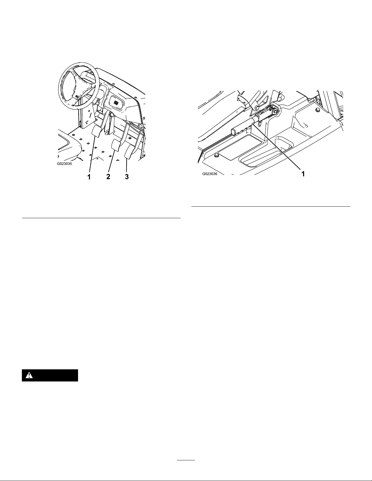
AcceleratorPedal
ParkingBrake
Theacceleratorpedal(Figure8)givesyoutheability
tovarythegroundspeedofthesprayer.Pressingthe
pedalincreasesgroundspeed.Releasingthepedal
willslowthesprayerandtheenginewillidle.
Figure8
1.Clutchpedal
2.Brakepedal
3.Acceleratorpedal
Theparkingbrakeisalargelevertotheleftofthe
seat(Figure9).Engagetheparkingbrakewhenever
youplanonleavingtheseattopreventaccidental
movementofthesprayer.T oengagetheparking
brake,pullupandbackonthelever.Todisengage,
pushitforwardanddown.Ifthesprayerisparked
onasteepgrade,applytheparkingbrakeandplace
blocksatthedownhillsideofthewheels.
g023035
1.Parkingbrakelever
Figure9
g023036
ClutchPedal
Theclutchpedal(Figure8)mustbefullypressedto
disengageclutchwhenstartingtheengineorshifting
transmissiongears.Releasethepedalsmoothlywhen
thetransmissionisingeartopreventunnecessary
wearonthetransmissionandotherrelatedparts.
Important:Donotridetheclutchpedalduring
operation.Theclutchpedalmustbefullyoutor
theclutchwillslipcausingheatandwear.Never
holdthevehiclestoppedonahillusingtheclutch
pedal.Damagetotheclutchmayoccur.
BrakePedal
Usethebrakepedaltostoporslowthesprayer
(Figure8).
CAUTION
Brakescanbecomewornorcanbeadjusted
incorrectlyresultinginpersonalinjury.
ChokeControl
Thechokecontrolisasmallknobbehindtherange
selector(Figure7).T ostartacoldengine,pullthe
chokecontrolup.Aftertheenginestarts,regulatethe
choketokeeptheenginerunningsmoothly.Assoon
aspossible,pushthecontroldowntotheOffposition.
Awarmenginerequireslittleornochoking.
RangeSelector
Therangeselector(Figure7)has5positions:3
forwardspeeds,Neutral,andReverse.Theengine
willstartonlywhentherangeselectorisintheNeutral
position.
IgnitionSwitch
Theignitionswitch(Figure7),usedtostartandstop
theengine,has3positions:Stop,Run,andStart.
RotatethekeyclockwisetotheStartpositiontostart
theengineandreleaseittotheRunpositionwhen
started.RotatethekeytotheStoppositiontostop
theengine.
Ifbrakepedaltravelstowithin2.5cm(1inch)
ofthesprayeroorboard,adjustorrepairthe
brakes.
HeadlightSwitch
Toggletheswitchtooperatetheheadlights(Figure
7).Pushitforwardtoturnthelightsonandrearward
toturnthemoff.
20

Throttle/SpeedLockSwitch
WhentherangeselectorisintheNeutralposition,you
canusetheacceleratorpedaltospeeduptheengine,
thenpushtheswitchbelowtheInfoCenterforwardto
settheengineatthatspeed.Thisisnecessarytorun
thechemicalagitationwhilestationaryoroperating
attachmentssuchasthehandsprayer(Figure7).
Important:Therangeselectormustbeinthe
Neutralpositionandtheparkingbrakemustbe
setfortheswitchtowork.
FuelGauge
Thefuelgaugeislocatedontopofthefueltank,on
theleftsideofthemachine,andshowstheamountof
fuelinthetank.
MasterBoomSwitch
Themasterboomswitch(Figure7)islocatedonthe
sideoftheconsoleandtotherightoftheoperator.It
allowsyoutostartorstopthesprayoperation.Press
theswitchtoenableordisablethespraysystem.
accidentallychangingtheapplicationrate.Turnthe
keyclockwisetotheunlockedpositiontoenablethe
applicationrateswitch.
BoomLift
Theboomliftswitchesarelocatedonthecontrol
panelandareusedtoraisetheleftandrightboom
respectively.
HourMeter
Thehourmeterindicatesthetotalnumberofhours
theenginehasrun.Thisnumberisdisplayedonthe
rstscreenoftheInfoCenter.Thehourmeterstarts
tofunctionwheneverthekeyisturnedtotheRun
position.
SonicBoom(Optional)
TheSonicBoomswitchisarockerswitchusedto
operatetheSonicBoom.Toggletheswitchforward
forautomatic,rearwardformanualandcenterforOff.
FoamMarkerSwitchLocations
Boom-SectionSwitches
Theboomswitchesarelocatedonthecontrolpanel
(Figure7).Toggleeachswitchforwardtoturnthe
correspondingboomsectiononandrearwardtoturn
themoff.Whentheswitchisturnedon,alightonthe
switchilluminates.Theseswitcheswillonlyaffectthe
spraysystemwhenthemasterboomswitchison.
PumpSwitch
Thepumpswitchislocatedonthecontrolpaneltothe
rightoftheseat(Figure7).Togglethisswitchforward
torunthepumporrearwardtostopthepump.
Important:Thepumpswitchwillonlyengage
whentheengineisatlowidletoavoiddamaging
thepumpdrive.
ApplicationRateSwitch
Theapplicationrateswitchislocatedonthecontrol
paneltotherightoftheseat(Figure7).Pressand
holdtheswitchforwardtoincreasethespraysystem
pressure,orpressandholditrearwardtodecrease
thepressure.
Supervisor(RateLockout)Switch
Thesupervisorswitchislocatedonthecontrolpanel
totherightoftheseat(Figure7).Turnthekey
counterclockwisetothelockedpositiontodisablethe
applicationrateswitch,therebykeepinganyonefrom
(Optional)
IfyouinstalltheFoamMarkerkit,youwilladdswitches
tothecontrolpanelforcontrollingtheiroperation.The
sprayercomeswithplasticplugsintheselocations.
Regulating(RateControl)Valve
Thisvalve,locatedbehindthetank(Figure9),controls
theamountofuidthatisroutedtotheboomsorthe
ratereturntothetank.
Figure10
1.Regulating(ratecontrol)
valve
2.Agitationvalve5.Boom-sectionvalves
3.Masterboomvalve
4.Flowmeter
g028051
21

MasterBoomValve
Themasterboomvalve(Figure10)isusedtostopthe
owtotheowmeterandboomvalves.
Specications
Note:Specicationsanddesignaresubjectto
changewithoutnotice.
Flowmeter
Theowmetermeasurestheowrateoftheuidfor
usebytheInfoCentersystem(Figure10).
Boom-SectionValves
Thesevalvesturnthethreeboomsectionsonoroff
(Figure10).
Boom-SectionBypassValve
Theboombypassredirectstheuidowforaboom
sectiontothetankwhenyouturnofftheboomsection.
Youcanadjusttheboombypasstoensurethatthe
boompressureremainsconstantnomatterhowmany
boomssectionsareon.RefertoCalibratingthe
Boom-SectionBypassV alves(page33).
AgitationValve
Thisvalveislocatedontherearofthetank(Figure
10).Whenagitationison,theowisdirectedthrough
theagitationnozzlesinthetank.Whenagitationisoff,
theowisdirectedthroughthepumpsuction.
PressureGauge
Thepressuregaugeislocatedonthecontrolpanel
(Figure7).Thisgaugeshowsthepressureoftheuid
inthesysteminpsiandkPa.
Weightwithstandardspray
system,empty,without
operator
Weightwithstandardspray
system,full,withoutoperator
Maximumgrossvehicleweight
(GVW)(onlevelground)
Overalllengthwithstandard
spraysystem
Overallheightwithstandard
spraysystem
Overallheightwithstandard
spraysystemtothetopofthe
boomsstoredintheXposition
Overallwidthwithstandard
spraysystemboomsstoredin
theXposition
Groundclearance14cm(5.5inches)
Wheelbase
Tankcapacity(includesthe
CE5%overow)
953kg(2,100lb)
1,678kg(3,700lb)
1,814kg(4,000lb)
343cm(135inches)
191cm(75inches)
246cm(97inches)
178cm(70inches)
155cm(61inches)
662L(175USgallons)
Attachments/Accessories
AselectionofT oroapprovedattachmentsand
accessoriesisavailableforusewiththemachineto
enhanceandexpanditscapabilities.Contactyour
AuthorizedServiceDealerorDistributororgoto
www.T oro.comforalistofallapprovedattachments
andaccessories.
InfoCenterLCDDisplay
TheInfoCenterLCDdisplayshowsinformationabout
yourmachineandbatterypack,suchasthecurrent
batterycharge,thespeed,diagnosticsinformation,
andmore(Figure7).
Formoreinformation,refertoUsingtheInfoCenter
LCDDisplay(page30).
22
Operation
Note:Determinetheleftandrightsidesofthe
machinefromthenormaloperatingposition.
CheckingtheTirePressure
Checkthetirepressureevery8hoursordailyto
ensureproperlevels.Fillthetiresto138kPa(20psi).
Also,checkthetiresforwearordamage.
SafetyFirst
Pleasecarefullyreadallofthesafetyinstructionsand
decalsinthesafetysection.Knowingthisinformation
couldhelpyouorbystandersavoidinjury.
PreparingtoDrivethe
SprayerfortheFirstTime
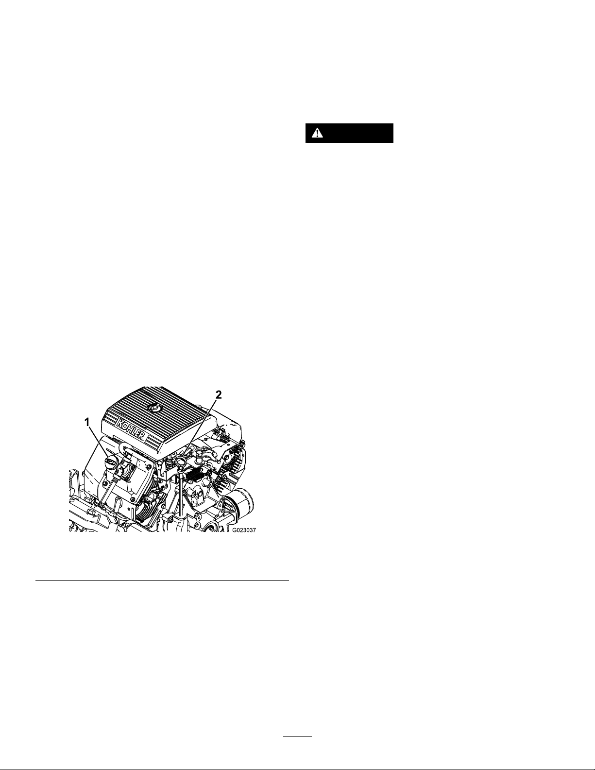
CheckingtheEngineOil
Theengineisshippedwithoilinthecrankcase;
however,thelevelofoilmustbecheckedbeforeyou
rststarttheengineandafteryouhaverunit.
1.Positionthemachineonalevelsurface.
2.Removethedipstickandwipeitwithacleanrag
(Figure11).
3.Insertthedipstickintothetubeandmakesureit
isseatedfully .Removethedipstickandcheck
theoillevel.
AddingFuel
DANGER
Incertainconditions,gasolineisextremely
ammableandhighlyexplosive.Areor
explosionfromgasolinecanburnyouand
othersandcandamageproperty.
•Fillthefueltankoutdoors,inanopenarea,
whentheengineiscold.Wipeupany
gasolinethatspills.
•Neverllthefueltankinsideanenclosed
trailer.
•Donotllthefueltankcompletelyfull.Add
gasolinetothefueltankuntilthelevelis6
to13mm(1/4to1/2inch)belowthebottom
ofthellerneck.Thisemptyspaceinthe
tankallowsgasolinetoexpand.
•Neversmokewhenhandlinggasoline,and
stayawayfromanopenameorwhere
gasolinefumesmaybeignitedbyaspark.
Figure11
1.Fillercap2.Dipstick
4.Iftheoillevelislow,removethellercapfrom
thevalvecover(Figure11)andpouroilintothe
openinguntiltheoillevelisuptotheFullmark
onthedipstick;refertoChangingtheEngineOil
(page42)fortheproperoiltypeandviscosity .
Addtheoilslowlyandchecktheleveloften
duringthisprocess.Donotoverll.
•Storegasolineinanapprovedcontainer
andkeepitoutofthereachofchildren.
Neverbuymorethana30-daysupplyof
gasoline.
•Donotoperatewithoutentireexhaust
systeminplaceandinproperworking
condition.
g023037
5.Installthedipstickrmlyinplace.
23

DANGER
Incertainconditionsduringfueling,static
electricitycanbereleasedcausingaspark
whichcanignitethegasolinevapors.Are
orexplosionfromgasolinecanburnyouand
othersandcandamageproperty.
•Alwaysplacegasolinecontainersonthe
groundawayfromyourvehiclebefore
lling.
•Donotllgasolinecontainersinsidea
vehicleoronatruckortrailerbedbecause
interiorcarpetsorplastictruckbedliners
mayinsulatethecontainerandslowthe
lossofanystaticcharge.
•Whenpractical,removegas-powered
equipmentfromthetruckortrailerand
refueltheequipmentwithitswheelsonthe
ground.
•Ifthisisnotpossible,thenrefuelsuch
equipmentonatruckortrailerfroma
portablecontainer,ratherthanfroma
gasolinedispensernozzle.
•Ifagasolinedispensernozzlemustbe
used,keepthenozzleincontactwiththe
rimofthefueltankorcontaineropeningat
alltimesuntilfuelingiscomplete.
RecommendedFuel
•Forbestresults,useonlyclean,fresh(lessthan
30daysold),unleadedgasolinewithanoctane
ratingof87orhigher((R+M)/2ratingmethod).
•ETHANOL:Gasolinewithupto10%ethanol
(gasohol)or15%MTBE(methyltertiarybutyl
ether)byvolumeisacceptable.EthanolandMTBE
arenotthesame.Gasolinewith15%ethanol
(E15)byvolumeisnotapprovedforuse.Never
usegasolinethatcontainsmorethan10%ethanol
byvolume,suchasE15(contains15%ethanol),
E20(contains20%ethanol),orE85(containsup
to85%ethanol).Usingunapprovedgasoline
maycauseperformanceproblemsand/orengine
damagewhichmaynotbecoveredunderwarranty
•Donotusegasolinecontainingmethanol.
•Donotstorefueleitherinthefueltankorfuel
containersoverthewinterunlessafuelstabilizer
isused.
•Donotaddoiltogasoline.
FillingtheFuelTank
Thefueltankcapacityisapproximately19L(5US
gallons).
Note:Thefueltankcapcontainsagaugewhich
showsthefuellevel;checkitfrequently.
1.Shuttheengineoffandsettheparkingbrake.
2.Cleantheareaaroundthefuel-tankcap(Figure
12).
g023038
Figure12
1.Fuel-tankcap2.Fuelgauge
3.Removethefueltankcap.
4.Fillthetanktoaboutoneinchbelowthetopof
thetank,(bottomofthellerneck).Thisspace
inthetankallowsgasolinetoexpand.Donot
overll.
5.Installthefuel-tankcapsecurely.
6.Wipeupanyfuelthatmayhavespilled.
PerformingthePre-Starting
Checks
Checkthefollowingitemseachtimeyoubeginusing
thesprayerfortheday:
•Checkthetirepressure.
Note:Thesetiresaredifferentthancartires;they
requirelesspressuretominimizeturfcompaction
anddamage.
•Checkalluidlevelsandaddtheappropriate
amountofspecieduids,ifanyarefoundtobe
low.
•Checkthebrakepedaloperation.
•Checktoseethatthelightsareworking.
•Turnthesteeringwheeltotheleftandrightto
checksteeringresponse.
•Checkforoilleaks,looseparts,andanyother
noticeablemalfunctions.Makesurethatthe
engineisoffandallmovingpartshavestopped
beforecheckingforoilleaks,looseparts,and
othermalfunctions.
Ifanyoftheaboveitemsarenotcorrect,notifyyour
mechanicorcheckwithyoursupervisorbeforetaking
thesprayeroutfortheday.Yoursupervisormaywant
youtocheckotheritemsonadailybasis,soaskwhat
yourresponsibilitiesare.
24

DrivingtheSprayer
StartingtheEngine
1.Sitintheoperator'sseat,insertthekeyintothe
ignitionswitch,androtatethekeyclockwiseto
theRunposition.
Note:LeavingtheignitionswitchintheOn
positionforlongperiodsoftimewithoutrunning
theenginewilldischargethebattery .
Important:Donotattempttopushortow
thevehicletogetitstarted.Damagetothe
drivetraincouldresult.
2.Presstheclutchandmovetherangeselector
totheNeutralposition.
3.EnsurethatthepumpswitchisintheOff
position.
4.Iftheengineiscold,pullthechokeknobup.
Important:Donotusethechokeifthe
engineiswarm.
5.TurnthekeytotheStartpositionuntiltheengine
starts.
Important:DonotholdthekeyintheStart
positionformorethan10seconds.Ifthe
enginehasnotstartedafter10seconds,wait
1minutebeforetryingagain.Donotattempt
topushortowthesprayertostarttheengine.
6.Oncetheenginestarts,pushthechokeknob
downslowly.
Driving
1.Releasetheparkingbrake.
2.Fullypresstheclutchpedal.
3.Movethegearshiftleverto1stgear.
4.Releasetheclutchpedalsmoothlywhile
pressingtheacceleratorpedal.
5.Whenthevehiclegainsenoughspeed,remove
yourfootfromtheacceleratorpedal,fullypress
theclutchpedal,movethegearshiftlevertothe
nextgearandreleasetheclutchpedalwhile
pressingtheacceleratorpedal.Repeatthe
procedureuntilthedesiredspeedisattained.
Important:Alwaysstopthevehiclebefore
shiftingfromaforwardgeartoreverseor
fromreversetoaforwardgear.
Note:Avoidlongperiodsofengineidling.
SettingtheThrottleLock
Note:Theparkingbrakeandspraypumpmustbeon
andtherangeselectorinneutraltosetthethrottle
lock.
1.Pressdownontheacceleratorpedaltoobtain
thedesiredenginerpm.
2.Togglethethrottlelockswitchonthecontrol
paneltotheOnposition.
3.Toreleasethethrottlelock,toggletheswitch
totheOffposition,orpressthebrakeorclutch
pedal.
SettingtheSpeedLock
Note:Beforesettingthespeedlock,theoperator
mustbesittingintheoperator’sseatwiththeparking
brakeoff,thepumpon,andtherangeselectoringear.
1.Pressdownontheacceleratorpedaltoobtain
thedesiredenginespeed.
2.Togglethespeedlockswitchonthecontrol
paneltotheOnposition.
3.Toreleasethespeedlock,toggletheswitchto
theOffposition,orpressthebrakeorclutch
pedal.
StoppingtheEngine
1.Presstheclutchandapplythebraketostopthe
sprayer.
2.Pulltheparkingbrakeleverupandbacktosetit.
3.Movetherangeselectoroutofgearintothe
Neutralposition.
4.TurntheignitionkeytotheStopposition.
5.Removethekeyfromtheswitchtoprevent
accidentalstarting.
Usethechartbelowtodeterminetheground
speedofanemptyvehicleat3400rpm.
Gear
166.4:15.63.5
238.1:19.86.1
319.6:119.211.9
R80.7:14.72.9
Ratio
Speed
(km/h)
BreakinginaNewSprayer
Toprovideproperperformanceandlongsprayerlife,
Speed(mph)
followtheseguidelinesfortherst100operating
hours:
•Checktheuidandengineoillevelsregularly
andbealertforindicationsofoverheatinginany
componentofthesprayer.
•Afterstartingacoldengine,letitwarmupforabout
15secondsbeforeaccelerating.
25
•Tooptimizethebrakesystem,burnish(breakin)
thebrakesasfollows:
3.Liftupontheboomandremovethepin(Figure
13),andslowlylowertheboomtotheground.
1.Load454L(120USgallons)ofwaterinto
thetank.
2.Movethemachinetoandopen-levelarea.
3.Drivethemachineatfullspeed.
4.Applythebrakesrapidly .
Note:Stopthemachineinastraightline
withoutlockingupthetires.
5.Wait1minutetoallowthebrakestocool.
6.Repeatsteps3through5an9additional
times.
•Avoidracingtheengine.
•Varythesprayerspeedduringoperation.Avoid
faststartsandquickstops.
•RefertotheMaintenance(page36)foranyspecial
low-hourchecks.
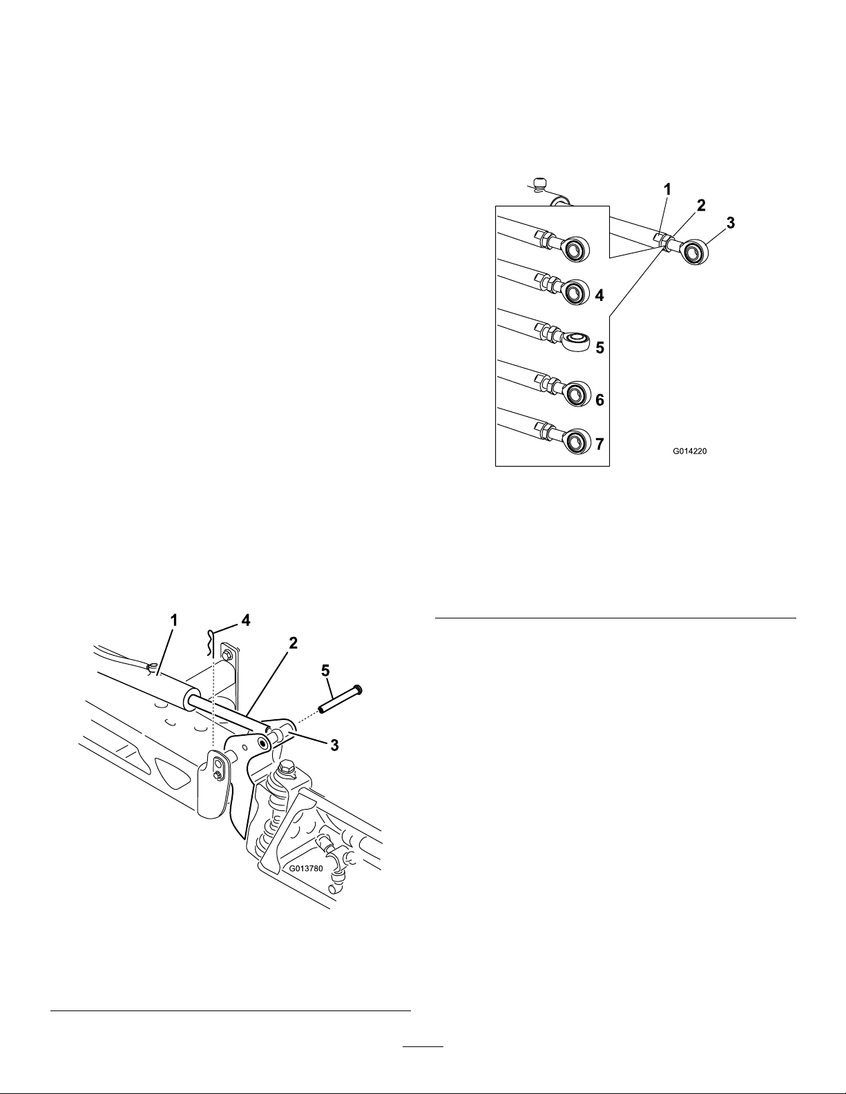
AdjustingtheBoomsto
Level
Thefollowingprocedurecanbeusedtoadjustthe
actuatorsonthecenterboomtokeeptheleftand
rightboomsatlevel.
1.Extendtheboomstothesprayposition.
2.Removethecotterpinfromthepivotpin(Figure
13).
4.Inspectthepinforanydamage,andreplaceit
ifnecessary.
5.Useawrenchontheatsidesoftheactuatorrod
toimmobilizeit,thenloosenthejamnuttoallow
theeyeletrodtobemanipulated(Figure14).
Figure14
1.Flatontheactuatorrod5.Eyeletadjusted
2.Jamnut
3.Eyelet7.Jamnuttightenedtolock
4.Jamnutloosened
6.Eyeletpositionfor
assembly
newposition
g014220
Figure13
1.Actuator
2.Actuatorrod5.Pin
3.Boompivotpinhousing
6.Turntheeyeletrodintheactuatorrodtoshorten
orlengthentheextendedactuatortothedesired
position(Figure14).
Note:Theeyeletrodmustbeturnedinhalfor
completerevolutionstoallowthereassembly
oftherodtotheboom.
7.Oncethedesiredpositionhasbeenachieved,
tightenthejamnuttosecuretheactuatorand
eyeletrod.
8.Raisetheboomtoalignthepivotwiththe
actuatorrod.Whileholdingtheboom,insertthe
pinthroughbothboompivotandactuatorrod
(Figure13).
9.Withthepininplace,releasetheboomand
g013780
4.Cotter
securethepinwiththecotterpreviously
removed.
10.Repeatthisprocedureforeachactuatorrod
bearing,ifnecessary.
26

OperatingtheSprayer
FillingtheSprayTank
TooperatetheMultiProSprayer,rstllthespray
tank,thenapplythesolutiontotheworkarea,and
nallycleanthetank.Itisimportantthatyoucomplete
all3ofthesestepsinsuccessiontoavoiddamaging
thesprayer.Forexample,donotmixandadd
chemicalsinthespraytankatnightandthenspray
inthemorning.Thiswouldleadtoseparationofthe
chemicalsandtopossibledamagetothesprayer
components.
CAUTION
Chemicalsarehazardousandcancause
personalinjury.
•Readthedirectionsonthechemicallabels
beforehandlingthechemicals,andfollow
allmanufacturerrecommendationsand
precautions.
•Keepchemicalsawayfromyourskin.
Shouldcontactoccur,washtheaffected
areathoroughlywithsoapandcleanwater.
•Weargogglesandanyotherprotective
equipmentrecommendedbythechemical
manufacturer.
TheMultiProSprayerhasbeenspecicallydesigned
tohavehighdurabilityinordertogiveitthelong
sprayerlifeyouneed.Differentmaterialshavebeen
chosenforspecicreasonsatdifferentlocationson
yoursprayertomeetthisgoal.Unfortunately,thereis
nosinglematerialwhichisperfectforallforeseeable
applications.
Somechemicalsaremoreaggressivethanothers,
andeachchemicalinteractsdifferentlywithvarious
materials.Someconsistencies(e.g.wettable
powders,charcoal)aremoreabrasiveandlead
tohigher-than-normalwearrates.Ifachemicalis
availableinaformulationthatwouldprovideincreased
lifetothesprayer,usethisalternativeformulation.
Asalways,remembertocleanyoursprayerthoroughly
afterallapplications.Thiswilldothemosttoensure
thatyoursprayerhasalongandtrouble-freelife.
FillingtheFreshWaterTank
Alwaysllthefreshwatertankwithcleanwaterbefore
handlingormixinganychemicals.
Thefreshwatertankislocatedontheleftsideofthe
ROPSbar.Itsuppliesasourceoffreshwaterforyou
towashchemicalsoffofyourskin,eyes,orother
surfacesinthecaseofaccidentalexposure.
InstalltheChemicalPre-MixKitforoptimalmixingand
exteriortankcleanliness.
Important:Ensurethatthechemicalsyouwill
beusingarecompatibleforusewithViton(see
themanufacturer'slabel;itshouldindicateifit
isnotcompatible).Usingachemicalthatisnot
compatiblewithVitonwilldegradetheO-ringsin
thesprayer,causingleaks.
Important:Verifythattheproperapplication
ratehasbeensetpriortollingthetankwith
chemicals.
1.Stopthesprayeronalevelsurface,movethe
rangeselectortotheNeutralposition,stopthe
engine,andsettheparkingbrake.
2.Ensurethatthetankdrainvalveisclosed.
3.Determinetheamountofwaterneededtomix
theamountofchemicalyouneedasprescribed
bythechemicalmanufacturer.
4.Openthetankcoveronthespraytank.
Note:Thetankcoverislocatedinthecenterof
thetopofthetank.Toopenit,turnthefronthalf
ofthecovercounterclockwiseandswingitopen.
Youcanremovethestrainerinsideforcleaning.
Tosealthetank,closethecoverandrotatethe
fronthalfclockwise.
5.Add3/4oftherequiredwatertothespraytank
usingtheanti-siphonllreceptacle.
Important:Alwaysusefreshcleanwaterin
thespraytank.Donotpourconcentrateinto
anemptytank.
6.Starttheengineandsetthepumpswitchtothe
Onposition.
7.Presstheacceleratorpedaltotheoorandset
thethrottlelocktotheOnposition.
8.SetthemasterboomswitchtotheOffposition.
9.TurntheagitationvalvetotheOnposition.
10.Addtheproperamountofchemicalconcentrate
tothetankasdirectedbythechemical
manufacturer.
Important:Ifyouareusingawettable
powderwithoutfullagitation,mixthepowder
withasmallamountofwatertoformaslurry
beforeaddingittothetank.
11.Addtheremainingwatertothetank.
Toopenthefreshwatertankspigot,turntheleveron
thespigot.
27

OperatingtheBooms
Theboomliftswitchesonthesprayercontrolpanel
allowsyoutomovetheboomsbetweentransport
positionandspraypositionwithoutleavingthe
operator'sseat.Itisrecommendedtochangeboom
positionswhilethemachineisstationary .
ChangingtheBoomPosition
1.Stopthesprayeronlevelground.
2.Usetheboomliftswitchestolowerthebooms.
Note:Waituntiltheboomsreachthefull,
extendedsprayposition.
3.Whentheboomsneedtoberetracted,stopthe
sprayeronlevelground.
4.Usetheboomliftswitchestoraisethebooms,
untiltheyhavemovedcompletelyintoboom
transportcradleformingthe“X”transport
positionandtheboomcylindersarefully
retracted.
andneedagitationon:settheparkingbrake,turn
thepumpOn,presstheacceleratorpedaltooor,
andswitchthethrottlelocktotheOnposition.
Note:Thisprocedureassumesthatthepumpison
fromtheFillingtheSprayT ank(page27)procedure.
1.Lowertheboomsintoposition.
2.WiththemasterboomswitchintheOffposition,
setthe3boomswitchestotheOnposition.
3.Drivetothelocationwhereyouwillbespraying.
4.SetthemasterboomswitchtotheOnposition
tobeginspraying.
Note:TheInfoCenterwillshowtheboomswith
thesprayon.
Note:Whenthetankisnearlyempty,the
agitationmaycausefoaminginthetank.
Topreventthis,turntheagitationvalveoff.
Alternatively,youcanuseananti-foamingagent
inthetank.
5.Usetherateswitchtoadjustandsetatarget.
Important:T opreventdamagetothe
boomactuatorcylinder,makesurethatthe
actuatorsarefullyretractedbeforetransport.
UsingtheBoomTransportCradle
Thesprayerisequippedwithaboomtransportcradle
thathasauniquesafetyfeature.Intheeventof
accidentalboomcontactwithalowoverheadobject
whileinthetransportposition,theboom(s)canbe
pushedoutofthetransportcradles.Ifthisoccurs,the
boomswillcometorestinanearhorizontalposition
totherearofthevehicle.Whiletheboomswillnot
bedamagedduetothismovement,theyshouldbe
immediatelyputbackintothetransportcradle.
Important:Theboomscanbedamagedby
transportingtheminanypositionotherthanthe
“X”transportpositionusingtheboomtransport
cradle.
Toputtheboomsbackintothetransportcradle,lower
theboom(s)tothesprayposition,andthenraisethe
boom(s)backintothetransportposition.Makesure
thattheboomcylindersarefullyretractedtoprevent
actuatorroddamage.
6.Whennishedspraying,setthemasterboom
switchtotheOffpositiontoturnoffallbooms,
thensetthepumpswitchtotheOffposition.
SprayingTips
•Donotoverlapareasthatyouhavepreviously
sprayed.
•Watchforpluggednozzles.Replaceallwornor
damagednozzles.
•Usethemasterboomswitchtostopthesprayow
beforestoppingthesprayer.Oncestopped,place
therangeselectorintheNeutralpositionanduse
theneutralenginespeedlocktoholdtheengine
speeduptokeeptheagitationrunning.
•Youwillobtainbetterresultsifthesprayeris
movingwhenyouturntheboomson.
•Watchforchangesintheapplicationratethatmay
indicatethatyourspeedhaschangedbeyondthe
rangeofthenozzlesorthereisaproblemwiththe
spraysystem.
Spraying
Important:Toensurethatyoursolutionremains
wellmixed,usetheagitationfeaturewhenever
youhaveasolutioninthetank.Foragitationto
work,thepumpmustbeonandtheenginemust
berunningaboveanidle.Ifyoustopthevehicle
28
CleaningtheSprayer
Important:Youmustalwaysemptyandclean
thesprayerimmediatelyaftereachuse.Failure
todosomaycausethechemicalstodryor
thickeninthelines,cloggingthepumpandother
components.
Note:InstalltheTankCleanRinseKitforoptimal
tankcleaning.
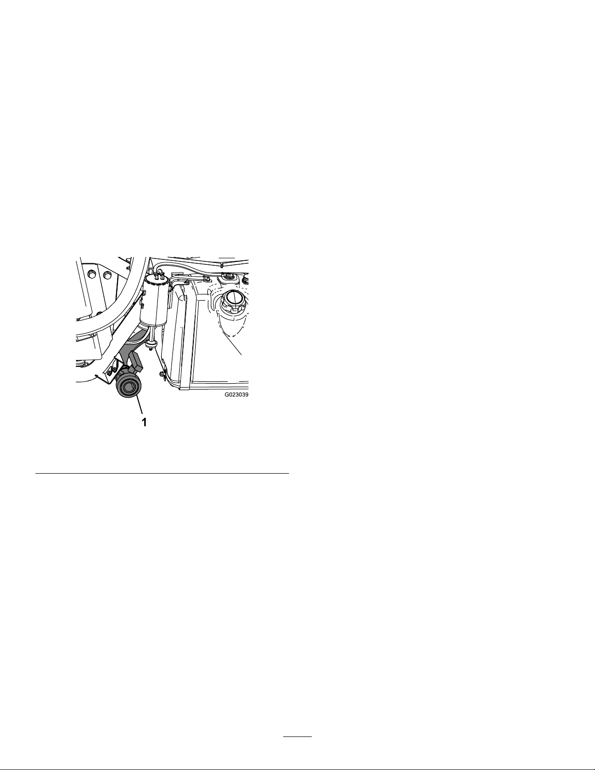
1.Stopthesprayer,settheparkingbrake,place
therangeselectorintheNeutralposition,and
turnofftheengine.Thetankwilldraintotheleft
sideofthemachine.
2.Locatethetankdrainvalveontheleftsideof
themachine(Figure15).
Note:Thevalveisbehindtheleftfender
bracketnexttothefueltank.
7.Starttheengine.
8.SetthepumpswitchtotheOnpositionand
usetheapplicationrateswitchtoincreasethe
pressuretoahighsetting.
9.WiththerangeselectorintheNeutralposition,
presstheacceleratorpedaltotheoorand
togglethethrottlelockswitchtotheOnposition.
10.EnsurethattheagitationvalveisintheOn
position.
11.Setthemasterboomswitchandboomcontrol
switchestotheOnpositiontobeginspraying.
12.Allowallofthewaterinthetanktosprayout
thoughthenozzles.
13.Checkthenozzlestoensurethattheyareall
sprayingcorrectly.
14.SetthemasterboomswitchtotheOffposition,
setthepumpswitchtotheOffposition,andstop
theengine.
15.Repeatsteps6through14atleast2moretimes
toensurethatthespraysystemisfullycleaned.
Figure15
1.Tankdrain
3.Removethevalvefromthebracket,andletthe
valverestontheground.
4.Openthevalvetodrainanyunusedmaterial
fromthetankanddisposeofitaccordingto
localcodesandthematerialmanufacturer's
instructions(Figure15).
Note:Thisallowsanyresidualmaterialinthe
linetodrain.
16.Onthelastcycle,runthelastfewgallonsof
waterthroughthedrainvalvetoclearthedrain
tubing.
17.Cleanthestrainer;refertoCleaningtheSuction
Strainer(page54).
Important:Ifyouusedwettablepowder
chemicals,cleanthestraineraftereachtank.
18.Usingagardenhose,sprayofftheoutsideofthe
g023039
sprayerwithcleanwater.
19.Removethenozzlesandcleanthembyhand.
Note:Replacedamagedorwornnozzles.
5.Whenthetankhasdrainedcompletely,closethe
drainvalveandinstallthevalveontothebracket
(Figure15).
6.Rinsetheinsideofthetankwithatleast22L
(6USgallons)ofcleanfreshwaterandclose
thecover.
Note:Y oucanuseacleaning/neutralizing
agentinthewaterasneeded.Onthenalrinse,
useonlyclean,clearwater.
29
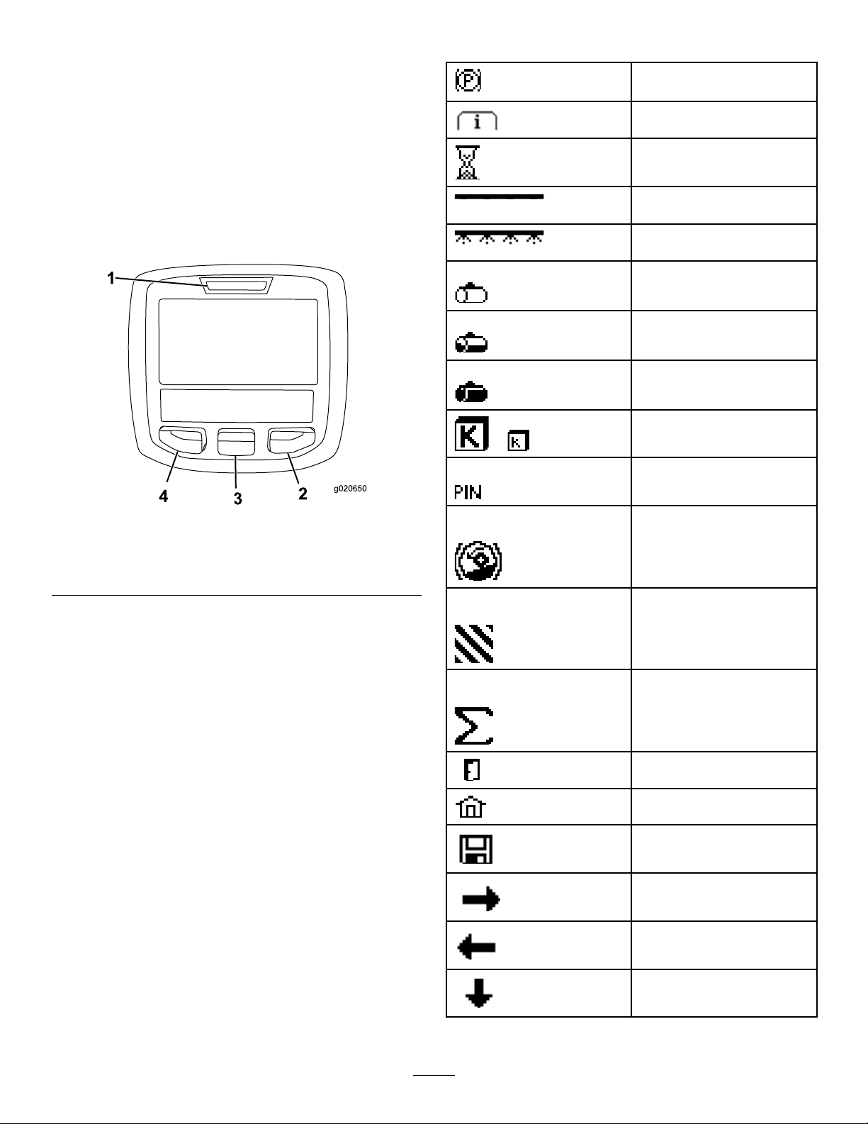
UsingtheInfoCenterLCD
Display
InfoCenterIconDescriptions
Parkingbrakeactive
TheInfoCenterLCDdisplayshowsinformationabout
yourmachine,suchastheoperatingstatus,various
diagnostics,andotherinformationaboutthemachine
(Figure16).Thereisasplashscreenandmain
informationscreenontheInfoCenter.Youcanswitch
betweenthesplashscreenandmaininformation
screenatanytimebypressinganyoftheInfoCenter
buttonsandthenselectingtheappropriatedirectional
arrow.
Figure16
Informationicon
Hourmeter
MasterboomOn/Boom
sectionOff
MasterboomOn/Boom
sectionOn
Emptyspraytank
Spraytankathalf
Fullspraytank
TURFunits(1,000square
or
g020650
feet)
CorrectPINcodeentered
Hill-assist
1.Indicatorlight3.Middlebutton
2.Rightbutton
4.Leftbutton
•Leftbutton,Menuaccess/Backbutton—pressthis
buttontoaccesstheInfoCentermenus.Youcan
alsouseittobackoutofanymenuthatyouare
currentlyusing.
•Middlebutton—usethisbuttontoscrolldown
menus.
•Rightbutton—usethisbuttontoopenamenu
wherearightarrowindicatedadditionalcontent.
Note:Thepurposeofeachbuttonmaychange
dependingonwhatisrequiredatthetime.Each
buttonwillhaveanicondisplayingitscurrentfunction.
Areasprayed
Volumesprayed
Exitmenu
Gotothehomescreen
Savevalue
Next
Previous
Scrolldown
30
Enter
UsingtheMenus
Increase
Decrease
Adjusttankvolume
Throttlelockisactive
Homescreen
Inactivescreen
Activescreen
Activehomescreen
Clearactivearea
Clearallareas
Changethenextvalueinthe
list
Adjustdigit
CheckPINentry/Calibration
verication
Selectthenextareafor
accumulation
ToaccesstheInfoCentermenusystem,pressthe
menuaccessbuttonwhileatthemainscreen.This
willbringyoutothemainmenu.Refertothefollowing
tablesforasynopsisoftheoptionsavailablefrom
themenus:
Calibration
MenuItemDescription
TestSpeedThismenusetsthetestspeedforcalibration.
Flow
Calibration
Speed
Calibration
SettingsMenu
MenuItemDescription
LowTankAlertThismenusetsthelowtankvolumealert.
UnitsThismenuchangestheunitsusedbythe
LanguageThismenuchangesthelanguageusedon
LCDBacklight
LCDContrast
Protected
Menus
ServiceMenu
MenuItemDescription
Faults
Hours
Thismenucalibratestheowmeter.
Thismenucalibratesthespeedsensor.
InfoCenter.ThemenuchoicesareEnglish,
SI(Metric),andTurf.
theInfoCenter.
Thismenuincreasesordecreasesthe
brightnessoftheLCDdisplay.
Thismenuchangesthecontrastbetweenthe
darkandlightareasoftheLCDdisplay.
Thismenugrantsaccesstoprotectedmenus.
Thismenudisplaysthemostrecentfaults
andlastclearedfault.
Thismenuliststhetotalnumberofhoursfor
keyon,machinerun,andpumpon.Italso
liststheserviceduehourandservicereset.
Tanklevellow
DiagnosticsMenu
MenuItemDescription
PumpsThismenuaccessesthepumpinputs,
momentaryrinse,andtimerinseoptions.
BoomsThismenuaccessestheboominputs,
qualiers,andoutputs.
ThrottleLockThismenuaccessesthethrottlelockinputs,
quantiers,andoutputs.
EngineRunThismenuaccessestheengineruninputs
andoutputs.
31

AboutMenu
MenuItemDescription
Model
SerialNumberThismenuliststheserialnumberofthe
S/WRev.Thismenuliststherevisionnumberofthe
Thismenuliststhemodelnumberofthe
machine.
machine.
machinesoftware.
Note:Ifyouinadvertentlychangethelanguage
orcontrasttoasettingwhereyoucannolonger
understandorviewthedisplay,contactyour
AuthorizedT oroDistributorforassistanceinresetting
thedisplay.
CalibratingtheSprayer
Flow
Operatorsuppliedequipment:Stopwatchcapable
ofmeasuring±1/10secondandacontainergraduated
in50ml(1-oz)increments.
Note:Beforeusingthesprayerforthersttime,if
youchangethenozzles,orasneeded,calibratethe
sprayerow,speed,andboombypass.
1.Fillthespraytankwithcleanwater.
Note:Ensurethatthereisenoughwaterinthe
tanktocompletethecalibration.
2.Settheparkingbrakeandturntheengineon.
3.SetthepumpswitchtotheOnposition,andturn
ontheagitation.
4.Pressdownontheacceleratorpedaluntilyou
reachthemaximumenginespeed,andtoggle
thethrottlelockswitchtotheOnposition.
5.Setall3boomswitchesandthemasterboom
switchtotheOnposition.
6.Turnthesupervisor(ratelockout)switchtothe
Unlockposition.
7.Preparetoperformacatchtestusingthe
graduatedcontainer.
8.Startat40psi(2.75bar)andusetheapplication
rateswitchtoadjustthespraypressuresoa
catchtestyieldstheamountslistedinthetable
below.
Note:Repeatthetest3timesandusethe
average.
NozzleColor
Yellow1896.4
Red37812.8
Brown47316.0
Gray
White
Blue94632.0
Green
Milliliters
collectedin15
seconds
56719.2
757
1,41948.0
Ouncescollected
in15seconds
25.6
9.Oncethecatchtesthasyieldedtheamounts
listedinthetableabove,setthesupervisorrate
lockoutswitchtotheLockposition.
10.Turnoffthemasterboomswitch.
11.OntheInfoCenter,navigatetotheCalibration
menuandselectFlowCalibrationasfollows:
Note:SelectingtheHomeScreeniconatany
timewillcancelcalibrations.
A.Pressthecenterbuttonoftheinfocenter
twicetoaccessthemenus.
B.Enterthecalibrationmenubypressingthe
RHbuttonontheinfocenter.
C.SelectFlowCalbyhighlightingFlowCal
andpresstheRHbuttonontheInfoCenter.
D.Inthenextscreen,entertheknownquantity
ofwaterthatwillbesprayedoutofthe
boomsforthecalibrationprocedure;referto
thechartbelow.
E.Oncetheknownquantityhasbeenentered
presstheRHbuttonontheinfocenter.
12.Usingtheplus(+)andminus(-)symbols,enter
theowvolumeaccordingtothetablebelow.
NozzleColor
Yellow4211
Red8322
Brown10628
Gray
White16744
Blue208
Green
Liters
12533
31483
USGallons
55
13.Turnonthemasterboomswitchfor5minutes.
32

Note:Asthemachinesprays,theinfocenter
willdisplaythequantityofuidit'scounting.
14.Aftertheveminutedurationofsprayingclick
thecheckmarkbypressingthecenterbutton
ontheinfocenter.
Note:Itisacceptableifthegallonsdisplayed
duringthecalibrationprocessdonotmatch
theknownquantityofwaterenteredintothe
InfoCenter.
15.After5minutes,turnoffthemasterboomswitch
andselectthecheckmarkontheInfoCenter.
Note:Calibrationisnowcomplete.
Calibratingthe
Boom-SectionBypass
Valves
Note:Beforeusingthesprayerforthersttime,if
youchangethenozzles,orasneeded,calibratethe
sprayerow,speed,andboombypass.
Selectanopenatareatoperformthisprocedure.
1.Fillthespraytankhalfwaywithcleanwater.
2.Lowerthesprayerbooms.
3.MovetherangeselectortotheNeutralposition,
andsettheparkingbrake.
CalibratingtheSprayer
Speed
Note:Beforeusingthesprayerforthersttime,if
youchangethenozzles,orasneeded,calibratethe
sprayerow,speed,andboombypass.
1.Fillthetankwithfreshwater.
2.Onanopen,atarea,markoffadistance
between45–152m(150–500ft).
Note:Tororecommendsmarkingoff152m
(500ft)formoreaccurateresults.
3.Starttheengineanddrivetothestartofthe
marked-offdistance.
Note:Alignthecenterofthefronttireswiththe
startinglineforthemostaccuratemeasurement.
4.OntheInfoCenter,navigatetotheCalibration
menuandselectSpeedCalibration.
Note:SelectingtheHomeScreeniconatany
timewillcancelcalibrations.
5.SelecttheNextarrow(→)ontheInfoCenter.
6.Usingtheplus(+)andminus(-)symbols,enter
themarked-offdistanceintotheInfoCenter.
7.Shiftthemachineintorstgearanddrivethe
markeddistanceinastraightlineatfullthrottle.
8.Stopthemachineatthemarked-offdistance
andselectthecheckmarkontheInfoCenter.
Note:Slowdownandrolltoastoptoalignthe
centerofthefronttireswiththenishline,for
themostaccuratemeasurement.
Note:Calibrationisnowcomplete.
4.Setthe3boomswitchestotheOnposition,but
leavethemasterboomswitchoff.
5.SetthepumpswitchtotheOnposition,andturn
ontheagitation.
6.Pressdownontheacceleratorpedaluntilyou
reachthemaximumenginespeed,andtoggle
thethrottlelockswitchtotheOnposition.
7.OntheInfoCenter,navigatetotheCalibration
menuandselectT estSpeed.
Note:SelectingtheHomeScreeniconatany
timewillcancelcalibrations.
8.Usingtheplus(+)andminus(-)symbols,enter
atestspeedof5.6Km/h(3.5mph),thenselect
theHomeicon.
9.Turnthesupervisor(ratelockout)switchto
theUnlockposition,andturnthemasterboom
switchon.
10.Usingtheapplicationrateswitch,adjustthe
applicationrateaccordingtothetablebelow.
NozzleApplicationRateT able
NozzleColorSI(Metric)
Yellow
Red
Brown
Gray478L/ha
White
Blue
Green1,190L/ha
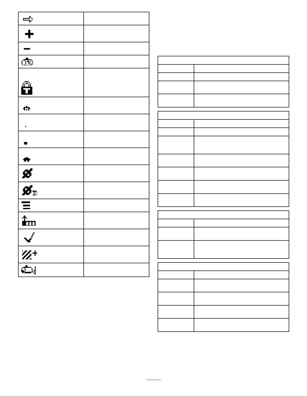
11.Turnofftheleftboomandadjusttheboom
bypassknob(Figure17)untilthepressure
readingisatthepreviouslyadjustedlevel
(typically40psior2.75bar).
159L/ha
319L/ha
394L/ha
637L/ha
796L/ha
English
17gpa0.39gpk
34gpa0.78gpk
42gpa0.96gpk
51gpa1.17gpk
68gpa1.56gpk
85gpa1.95gpk
127gpa2.91gpk
Turf
Note:Thenumberedindicatorsonthebypass
knobandneedleareforreferenceonly.
33
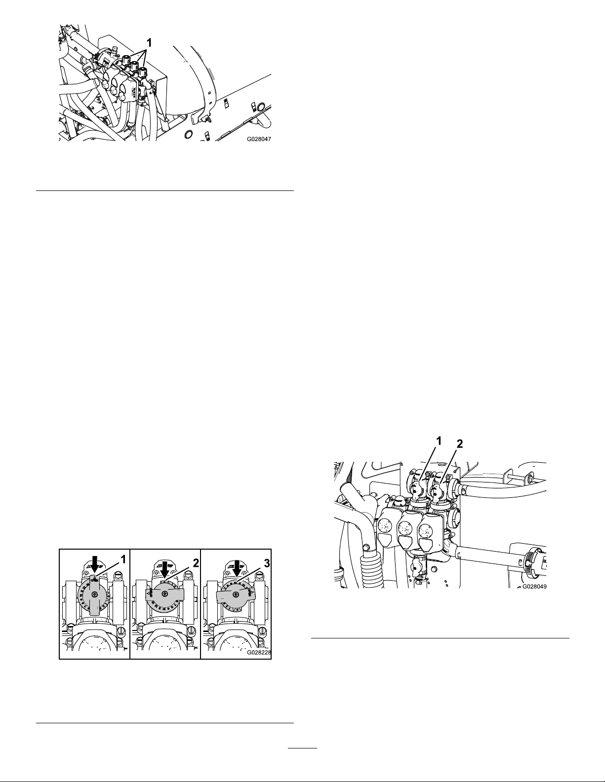
Figure17
1.Boom-sectionbypassadjustmentknobs
CalibratingtheAgitation
BypassValve
ServiceInterval:Y early
Selectanopenatareatoperformthisprocedure.
1.Fillthespraytankwithcleanwater.
2.Verifytheagitationcontrolvalveisopen.Ifithas
g028047
beenadjusted,openitcompletelyatthistime.
3.Settheparkingbrakeandstarttheengine.
4.SettherangeselectortoNeutral.
12.Turnontheleftboomandturnofftherightboom.
13.Adjusttherightboombypassknob(Figure17)
untilthepressurereadingisatthepreviously
adjustedlevel(typically40psior2.75bar).
14.Turnontherightboomandturnoffthecenter
boom.
15.Adjustthecenterboombypassknob(Figure17)
untilthepressurereadingisatthepreviously
adjustedlevel(typically40psior2.75bar).
16.Turnalltheboomsoff.
17.Turnthepumpoff.
Note:Calibrationisnowcomplete.
AgitationBypassValve
KnobPosition
•TheagitationbypassvalveisinthefullOpen
positionasshowninAofFigure18.
•TheagitationbypassvalveisintheClose(0)
positionasshowninBofFigure18.
5.SetthepumpswitchtotheOnposition.
6.Presstheacceleratorpedaltoachievemaximum
enginespeedandsetthethrottlelock.
7.Setthe3boom-sectionvalvestotheOffposition.
8.SetthemasterboomswitchtotheOnposition.
9.SetthesystempressuretoMaximum.
10.PresstheagitationswitchtotheOffpositionand
readthepressuregauge.
•Ifthereadingremainsat6.9bar(100psi)the
agitationbypassvalveisproperlycalibrated.
•Ifthepressuregaugereadsdifferently
continuetothenextstep.
11.Adjusttheagitationbypassvalve(Figure19)
onthebacksideoftheagitationvalveuntilthe
pressurereadingonthegaugeis6.9bar(100
psi).
•Theagitationbypassvalveisinanintermediate
(adjustedrelativetothepressuregaugeforthe
sprayersystem)positionasshowninCofFigure
18
Figure18
1.Open
2.Closed(0)
3.Intermediateposition
g028049
Figure19
1.Agitationbypassvalve2.Masterboombypass
12.PressthepumpswitchtotheOffposition,shift
g028228
34
thethrottlelevertotheIdleposition,andturn
theignitionswitchOff.
AdjustingtheMasterBoom
WARNING
BypassValve
Note:Adjustingthemasterboombypassvalve
reducesorincreasestheamountofowsenttothe
agitationnozzlesinthetankwhenthemasterboom
switchissettotheOffposition.
1.Fillthesprayertank1/2fullwithcleanwater.
2.Movethemachinetoanopenlevelsurface.
3.Settheparkingbrake.
4.SettherangeselectortotheNeutralposition.
5.SetthepumpswitchtotheOnposition.
6.SettheagitationswitchtotheOnposition.
7.SetthemasterboomswitchtotheOffposition.
8.Increasetheenginespeedtofullthrottleandset
thethrottlelocktotheOnposition.
9.Adjustthemasterboombypasshandleto
controltheamountofagitationoccurringinthe
tank(Figure19).
10.Reducethethrottlespeedtoidle.
11.Settheagitationswitchandpumpswitchtothe
Offposition.
Towingatexcessivespeedscouldcausea
lossofsteeringcontrol,resultinginpersonal
injury.
Nevertowthesprayerfasterthan8km/h
(5mph).
Towingthesprayerisa2–personjob.Ifthemachine
mustbemovedaconsiderabledistance,transportit
onatruckortrailer;refertoTransportingtheSprayer
(page35).
1.Attachatowlinetotheframe.
2.PuttherangeselectorintheNeutralposition
andreleasetheparkingbrake.
3.Towthesprayeratlessthan8km/h(5mph).
TransportingtheSprayer
Formovingthesprayerlongdistances,useatrailer.
Securethesprayertothetrailer.Also,makesurethat
theboomsaretieddownandsecure.Thereis1metal
looponthefrontoftheframeand2loopsontherear
oftheframe(Figure21).
12.Shutoffthemachine.
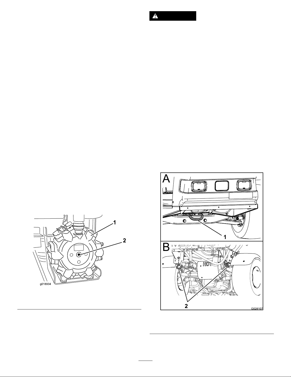
LocatingthePump
Thepumpislocatedundertheseat(Figure20).
Figure20
1.Pump
2.Greasetting
g018934
g028107
Figure21
TowingtheSprayer
Incaseofanemergency ,thesprayercanbetowed
forashortdistance.However,wedonotrecommend
thisasastandardprocedure.
1.Fronttie-downpoint2.Reartie-downpoints
35

Maintenance
Note:LookingforanElectricalSchematicorHydraulicSchematicforyourmachine?Downloadafreecopy
oftheschematicbyvisitingwww.T oro.comandsearchingforyourmachinefromtheManualslinkonthe
homepage.
Foradditionalinformationaboutthesprayersystem,refertoFigure44inSprayerFlowDiagram(page53).
Note:Determinetheleftandrightsidesofthemachinefromthenormaloperatingposition.
RecommendedMaintenanceSchedule(s)
MaintenanceService
Interval
Aftertherst8hours
Aftertherst50hours
Beforeeachuseordaily
Every50hours
Every100hours
MaintenanceProcedure
•T orquethewheellugnuts.
•Replacethehydrauliclter.
•Changetheengineoil.
•Checktheenginerotatingscreen.
•Checktheengineoil.
•Checkthetirepressure.
•Cleanthesuctionstrainer(moreoftenwhenusingwetablepowders).
•Lubricatethepump.
•Cleanandoiltheaircleanerfoamelement(moreoftenindusty,dirtyconditions).
•Checkthebatterycableconnections.
•Checkthebatteryelectrolytelevel.
•Lubricateallgreasettings.
•Lubricatetheboomhinges.
•Cleantheenginerotatingscreen(moreoftenindusty,dirtyconditions).
•Changetheengineoil(moreoftenwhenoperatingunderheavyloadorinhigh
temperature).
•Replacetheengineoillter.
•Replacethefuellter.
•T orquethewheellugnuts.
•Inspecttheconditionandwearofthetires.
•Checkfrontwheeltoe-in.
•Inspectthebrakes.
•Replacetheaircleanerpaperelement(moreoftenindusty,dirtyconditions).
•Changethesparkplugs.
Every200hours
Every400hours
Every800hours
Yearly
•Checktheparkingbrake.
•Checkthetransaxle/hydraulicuid.
•Inspectallhosesandconnectionsfordamageandproperattachment.
•Cleantheowmeter(moreoftenwhenusingwettablepowders).
•Completeallyearlymaintenanceprocedurespeciedintheengineoperator's
manual.
•Inspectthefuellines.
•Drainandcleanthefueltank.
•Changethepressurelter.
•Inspectthepumpdiaphragmsandreplaceifnecessary(seeanAuthorizedT oro
ServiceDistributor).
•Inspectthepumpcheckvalvesandreplaceifnecessary(seeanAuthorizedToro
ServiceDistributor).
•Inspectthecenterboomnylonpivotbushings.
•Changethetransaxle/hydraulicuidandcleanstrainer.
•Replacethehydrauliclter.
•Calibratetheagitationbypassvalve.
Important:Refertoyourengineowner'smanualforadditionalmaintenanceprocedures.
36

DailyMaintenanceChecklist
Duplicatethispageforroutineuse.
Checkthebrakeandparkingbrake
operation.
Checkthegearshift/neutraloperation.
Checkthefuellevel.
Checktheengineoillevel.
Checkthetransaxleoillevel.
Inspecttheairlter.
Inspecttheenginecoolingns.
Checkanyunusualenginenoises.
Checkanyunusualoperatingnoises.
Checkthetirepressure.
Checkforuidleaks.
Checktheinstrumentoperation.
Checktheacceleratoroperation.
Cleanthesuctionstrainer.
Checktoe-in.
Lubricateallgreasettings.
Touchupanddamagedpaint.
1
Fortheweekof: MaintenanceCheckItem
Mon.Tues.Wed.Thurs.Fri.
Sat.Sun.
1
Immediatelyaftereverywashing,regardlessoftheintervallisted
37
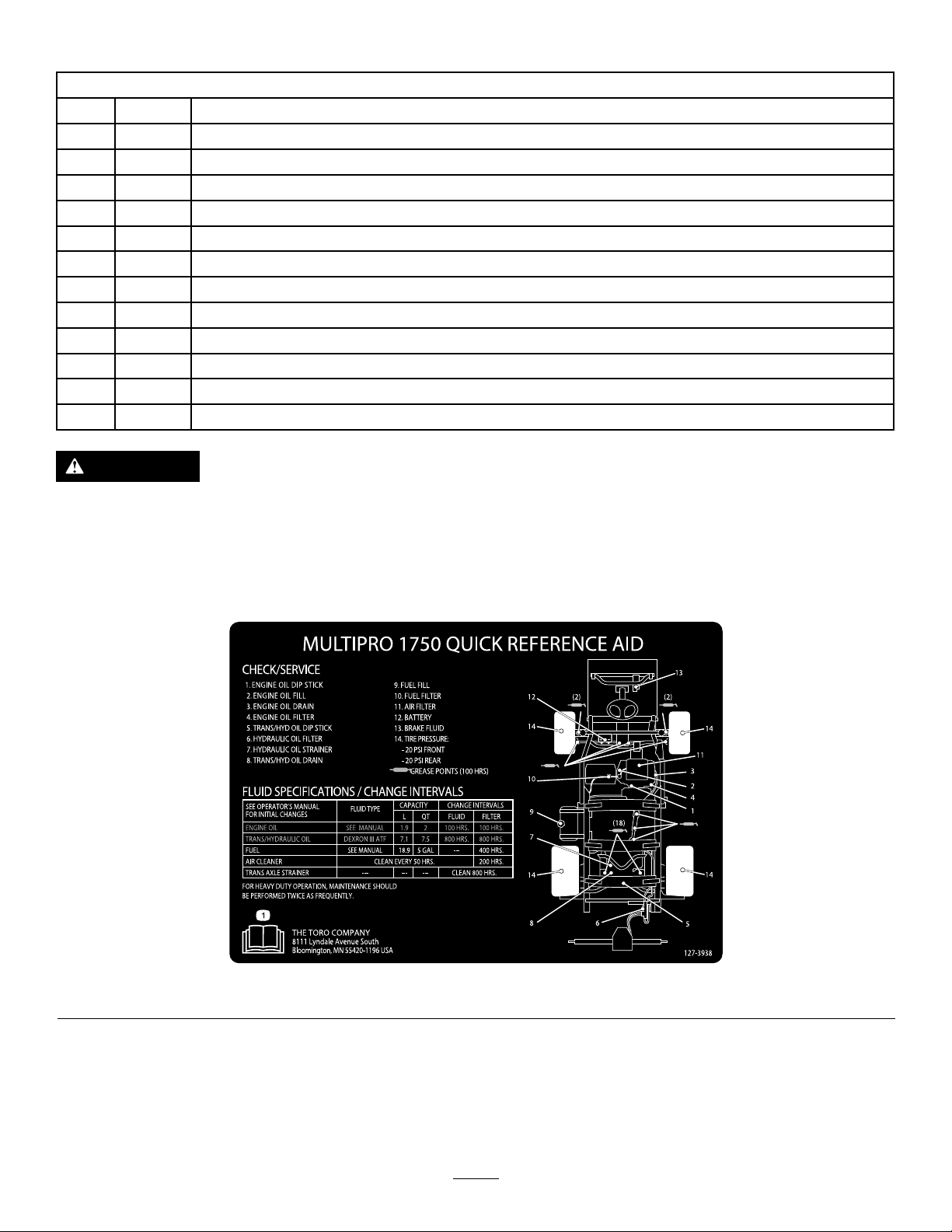
NotationforAreasofConcern
Inspectionperformedby:
ItemDate
1
2
3
4
5
6
7
8
9
10
11
12
CAUTION
Ifyouleavethekeyintheignitionswitch,someonecouldaccidentlystarttheengineand
seriouslyinjureyouorotherbystanders.
Information
Removethekeyfromtheignitionanddisconnectthewire(s)fromthesparkplug(s)before
youdoanymaintenance.Setthewire(s)asidesothatitdoesnotaccidentallycontactthe
sparkplug(s).
Figure22
decal127-3938
38
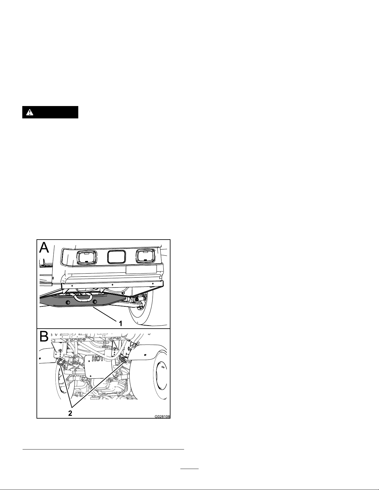
Pre-Maintenance
Lubrication
Procedures
GreasingtheSprayer
JackingUptheSprayer
Whenevertheengineisrunforroutinemaintenance
and/orenginediagnostics,therearwheelsofthe
sprayershouldbe2.5cm(1inch)offoftheground
withtherearaxlesupportedonjackstands.
DANGER
Asprayeronajackmaybeunstableandslip
offofthejack,injuringanyonebeneathit.
•Donotstarttheenginewhilethesprayer
isonajack.
•Alwaysremovethekeyfromtheignition
beforegettingoffofthesprayer.
•Blockthetireswhenthesprayerisona
jack.
Thejackingpointatthefrontofthesprayerisunder
thefrontcrossbar.Thejackingpointattherearofthe
sprayerisontherearframesupport,behindtherear
tiedowns(Figure23).
ServiceInterval:Every50hours—Lubricatethe
pump.
Every100hours/Y early(whichevercomes
rst)—Lubricateallgreasettings.
GreaseType:No.2general-purpose,lithium-based
grease
1.Wipethegreasettingcleansothatforeign
mattercannotbeforcedintothebearingor
bushing.
2.Pumpgreaseintothebearingorbushing.
3.Wipeoffexcessgrease.
SeeFigure22forthelocationofallofthegrease
points.
GreasingtheBoomHinges
ServiceInterval:Every100hours
Important:Iftheboomhingeiswashedwith
water,allwateranddebrismustbeclearedfrom
thehingeassemblyandfreshgreasemustbe
applied.
Figure23
GreaseType:No.2general-purpose,lithium-based
grease
1.Wipethegreasettingscleansothatforeign
mattercannotbeforcedintothebearingor
bushing.
2.Pumpgreaseintothebearingorbushingat
eachttingFigure24.
g028108
1.Frontjackingpoint2.Reartiedowns
39

Figure24
1.Greasetting
3.Wipeoffexcessgrease.
4.Repeattheprocedureforeachboompivot.
EngineMaintenance
CheckingtheAirIntake
Screen
ServiceInterval:Beforeeachuseordaily—Check
theenginerotatingscreen.
Every100hours—Cleantheenginerotating
screen(moreoftenindusty,dirtyconditions).
Checkandcleanasnecessarytheairintakescreen
onthefrontoftheenginebeforeeachuseordaily.
ServicingtheAirCleaner
ServiceInterval:Every50hours/Yearly(whichever
g002014
Every200hours/Yearly(whichevercomesrst)
(moreoftenindusty,dirtyconditions).
RemovingtheFoamandPaper
Elements
1.Settheparkingbrake,stopthepump,stopthe
engine,andremovetheignitionkey.
2.Releasethelatchonthebackoftheseatandlift
theseatforward.
3.Cleanaroundtheaircleanertopreventdirtfrom
gettingintotheengineandcausingdamage
(Figure25).
comesrst)(moreoftenindusty,
dirtyconditions).
Figure25
1.Aircleanercover5.Foamelement
2.Knob6.Paperelement
3.Covernut
4.Cover
4.Loosentheknobontheaircleanercoverand
removethecover(Figure25).
40
7.Rubberseal
8.Aircleanerbase
g001980
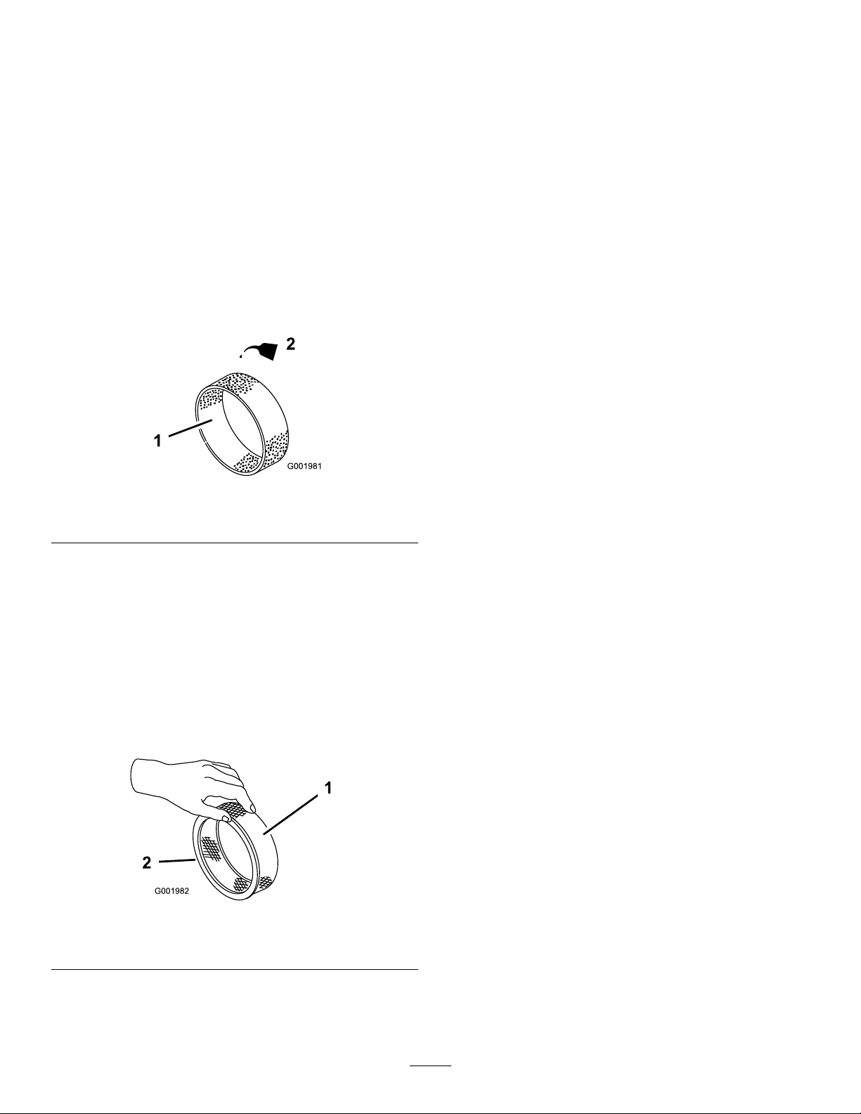
5.Carefullyslidethefoamelementoffthepaper
element(Figure25).
6.Unscrewthecovernutandremovethecover
andpaperelement(Figure25).
InstallingtheFoamandPaper
Elements
1.Carefullyslidethefoamelementontothepaper
aircleanerelement(Figure25).
CleaningtheFoamElement
1.Washthefoamelementinliquidsoapandwarm
water.
2.Whentheelementisclean,rinseitthoroughly.
3.Drytheelementbysqueezingitinacleancloth.
4.Put1or2ouncesofoilontheelement(Figure
26).
Important:Replacethefoamelementifit
istornorworn.
Figure26
1.Foamelement
2.Oil
2.Slidetheaircleanerassemblyandcoveronto
thelongrod.
3.Installthecovernutnger-tightagainstthecover
(Figure25).
Note:Ensurethattherubbersealisatagainst
theaircleanerbaseandcover.
4.Installtheaircleanercoverandknob(Figure
25).
5.Closeandlatchtheseat.
ServicingtheEngineOil
CrankcaseCapacityis2.0L(2.1qt)withthelter.
Usehigh-qualityengineoilthatmeetsthefollowing
specications:
•APIclassicationLevelrequired:SJ,JK,SL,or
g001981
higher.
•Preferredoil:SAE10W30(above0°F)
•Alternateoil:SAE5W30(below32°F)
5.Squeezetheelementtodistributetheoil.
CheckingthePaperElement
Inspectthepaperelementfortears,anoilylm,
damagetotherubberseal,excessivedirt,orother
damage(Figure27).Ifanyoftheseconditionsexit,
replacethelter.
Important:Donotcleanthepaperelementwith
pressurizedairorliquids,suchassolvent,gas,
orkerosene.
Figure27
1.Paperelement2.Rubberseal
ToroPremiumEngineOilisavailablefromyour
distributorineither10W30or5W30viscosity.Seethe
PartsCatalogforpartnumbers.
CheckingtheEngineOil
ServiceInterval:Beforeeachuseordaily
Every400hours/Yearly(whichevercomesrst)
Theengineisshippedwithoilinthecrankcase;
however,thelevelofoilmustbecheckedbeforeyou
rststarttheengineandafteryouhaverunit.
1.Positionthemachineonalevelsurface.
2.Removethedipstickandwipeitwithacleanrag
(Figure28).Insertthedipstickintothetubeand
makesureitisseatedfully.Removethedipstick
andchecktheoillevel.
g001982
Important:Topreventenginedamage,always
operatetheenginewiththecompletefoamand
paperaircleanerassemblyinstalled.
41

Figure28
1.Fillercap2.Dipstick
3.Iftheoillevelislow,removethellercapfrom
thevalvecover(Figure28)andpouroilintothe
openinguntiltheoillevelisuptotheFullmark
onthedipstick.Addtheoilslowlyandcheckthe
leveloftenduringthisprocess.Donotoverll.
4.Installthedipstickrmlyinplace.
ChangingtheEngineOil
ServiceInterval:Aftertherst50hours—Change
theengineoil.
Every100hours—Changetheengineoil(more
oftenwhenoperatingunderheavyloadorin
hightemperature).
1.Starttheengineandletitrunforveminutes.
Thiswarmstheoilsoitdrainsbetter.
g023037
g023045
Figure29
1.Oillter2.Oildrainplug
6.Whentheoilhasdrainedcompletely,replacethe
drainplugandtorqueitto13.6N-m(10ft-lb).
7.Disposeoftheusedoilatacertiedrecycling
center.
8.Slowlypourapproximately80%ofthespecied
amountofoilintotheoilllertube(Figure28).
9.Checktheoillevel.
10.Slowlyaddadditionaloiltobringtheoillevelto
thefullmarkonthedipstick.
Important:Overllingthecrankcasewithoil
maycauseenginedamage.
2.Settheparkingbrake,stopthepump,stopthe
engine,andremovetheignitionkey.
3.Releasethelatchonthebackoftheseatandlift
theseatforward.
CAUTION
Componentsundertheseatwillbehot
ifthesprayerhasbeenrunning.Ifyou
touchhotcomponentsyoumaybe
burned.
Allowthesprayertocoolbefore
performingmaintenanceortouching
componentsunderthehood.
4.Placeapanbelowtheoildrain.
5.Removethedrainplug(Figure29).
ChangingtheEngineOilFilter
ServiceInterval:Every100hours
1.Draintheoilfromtheengine;refertoChanging
theEngineOil(page42).
2.Removetheoillter(Figure29).
3.Wipethelteradaptergasketsurface.
4.Applyathincoatofnewoiltotherubbergasket
onthereplacementlter.
5.Installthereplacementoilltertothelter
adapter.Turntheoillterclockwiseuntilthe
rubbergasketcontactsthelteradapter,then
tightenthelteranadditional1/2turn(Figure
29).
6.Fillthecrankcasewiththecorrecttypeofnew
oil;refertoChangingtheEngineOil(page42),
steps8through10.
7.Disposeoftheusedoillteratacertied
recyclingcenter.
42
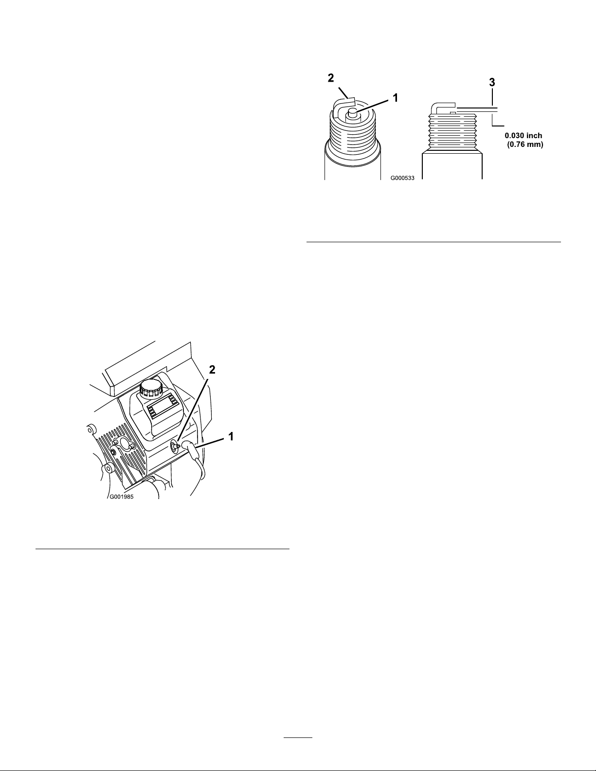
ChangingtheSparkPlugs
ServiceInterval:Every200hours
Type:ChampionRC-12YC(orequivalent)
AirGap:0.76mm(0.030inch)
Makesurethattheairgapbetweenthecenterand
sideelectrodesiscorrectbeforeinstallingthespark
plugs.Useasparkplugwrenchforremovingand
installingthesparkplugsandagappingtool/feeler
gaugetocheckandadjusttheairgap.
2.Checkthegapbetweenthecenterandside
electrodes(Figure31)andbendtheside
electrode,ifthegapisnotcorrect.
RemovingtheSparkPlug
1.Settheparkingbrake,stopthepump,stopthe
engine,andremovetheignitionkey.
2.Releasethelatchonthebackoftheseatandlift
theseatforward.
3.Pullthewiresoffthesparkplugs(Figure30).
4.Cleanaroundthesparkplugstopreventdirt
fromfallingintotheengineandpotentially
causingdamage.
5.Removethesparkplugsandmetalwashers.
g000533
Figure31
1.Centerelectrodeinsulator3.Airgap(nottoscale)
2.Sideelectrode
InstallingtheSparkPlugs
1.Installthesparkplugsandmetalwashers.
2.Tightenthesparkplugsto24.4to29.8N-m(18
to22ft-lb).
3.Pushthewiresontothesparkplugs(Figure30).
4.Closeandlatchtheseat.
Figure30
1.Sparkplugwire2.Sparkplug
CheckingtheSparkPlugs
1.Lookatthecenterofthesparkplugs(Figure31).
Ifyouseealightbrownorgraycoatingonthe
insulator,theengineisoperatingproperly.A
blackcoatingontheinsulatorusuallymeansthe
aircleanerisdirty.
Important:Donotcleanthesparkplugs.
Alwaysreplaceasparkplugwhenithasa
blackcoating,wornelectrodes,anoilylm,
orcracks.
g001985
43

FuelSystem
DrainingtheFuelTank
Maintenance
ReplacingtheFuelFilter
ServiceInterval:Every100hours—Replacethefuel
lter.
Every400hours/Y early(whichevercomes
rst)—Inspectthefuellines.
1.Settheparkingbrake,stopthepump,stopthe
engine,andremovetheignitionkey.
2.Releasethelatchonthebackoftheseatandlift
theseatforward.
3.Clampoffthehoseoneithersideofthefuellter
topreventgasfrompouringoutofthehoses
whenyouremovethelter.
4.Placeadrainpanunderthelter.
5.Squeezetheendsofthehoseclampstogether
andslidethemawayfromthelter(Figure32).
6.Removethelterfromthefuellines.
ServiceInterval:Every400hours/Yearly(whichever
comesrst)
Drainandcleanthefueltankifthefuelsystem
becomescontaminatedorifyouplantostorethe
machineforanextendedperiod.Usefresh,cleanfuel
toushoutthetank.
1.Transferthefuelfromthetankintoanapproved
fuelcontainerusingasiphonpump,orremove
thetankfromthemachineandpourthefuelout
ofthetankllspoutintothefuelcontainer.
Note:Ifyouremovethefueltank,youwillneed
toremovethefuelandreturnhosesfromthe
tankbeforeremovingthetank.
2.Replacethefuellter;refertoReplacingthe
FuelFilter(page44).
3.Flushthetankwithfresh,cleanfuel,ifnecessary.
4.Installthetankifyouremovedit.
5.Fillthetankwithfresh,cleanfuel.
Figure32
1.Hoseclamp3.Filter
2.Fuelline4.Flowdirectionarrow
7.Installanewlterandmovethehoseclamps
closetothelter.
Ensurethattheowdirectionarrowpoints
towardtheengine.
g001986
44

ElectricalSystem
Maintenance
LocatingtheFuses
Thereare2fuseblocksand1emptyslotinthe
electricalsystem.Theyarelocatedbeneaththeseat
(Figure33).
Figure33
1.Battery2.Fuseblocks
ServicingtheBattery
Important:Donotjumpstartthesprayer.
Alwayskeepthebatterycleanandfullycharged.Use
apapertoweltocleanthebatteryandbatterybox.If
thebatteryterminalsarecorroded,cleanthemwitha
solutionoffourpartswaterandonepartbakingsoda.
Applyalightcoatingofgreasetothebatteryterminals
topreventcorrosion.
Voltage:12voltwith280coldcrankingAmpsat0°F
WARNING
Incorrectbatterycableroutingcould
damagethesprayerandcablescausing
sparks.Sparkscancausethebattery
gassestoexplode,resultinginpersonal
injury.
•Alwaysdisconnectthenegative
(black)batterycablebefore
disconnectingthepositive(red)
cable.
•Alwaysreconnectthepositive(red)
batterycablebeforereconnectingthe
negative(black)cable.
WARNING
Batteryterminalsormetaltoolscould
shortagainstmetalsprayercomponents
causingsparks.Sparkscancausethe
g023046
batterygassestoexplode,resultingin
personalinjury.
•Whenremovingorinstallingthe
battery,donotallowthebattery
terminalstotouchanymetalpartsof
thesprayer.
•Donotallowmetaltoolstoshort
betweenthebatteryterminalsand
metalpartsofthesprayer.
•Alwayskeepthebatterystrapinplace
toprotectandsecurethebattery .
4.Disconnectthepositive(red)cablefromthe
batterypost.
5.Removethebatteryretainerandfasteners
(Figure33).
6.Removethebattery.
RemovingtheBattery
1.Positionthesprayeronalevelsurface,setthe
parkingbrake,stopthepump,stoptheengine,
andremovetheignitionkey.
2.Thebatteryislocatedontherighthandsideof
themachinebehindthepump(Figure33).
3.Disconnectthenegative(black)groundcable
fromthebatterypost.
InstallingtheBattery
ServiceInterval:Every50hours—Checkthebattery
cableconnections.
1.Setthebatteryonthebatteryboxsothatthe
batterypostsaretowardthefrontofthesprayer.
2.Installthebatteryretainerandsecureitwiththe
fastenersyouremovedpreviously(Figure33).
Important:Alwayskeepthebatteryretainer
inplacetoprotectandsecurethebattery.
3.Connectthepositive(red)cabletothepositive
(+)batterypostandthenegative(black)cable
tothenegative(-)batterypostusingthebolts
andwingnuts.Slidetherubberbootoverthe
positivebatterypost.
45

4.Installthebatterycoverandsecureitwiththe2
knobs(Figure33).
CheckingtheElectrolyteLevel
ServiceInterval:Every50hours
Note:Whenthemachineisinstoragecheckthe
batteryelectrolytelevelevery30days.
1.Loosentheknobsonthesidesofthebatterybox
andremovethebatterycover(Figure33).
2.Removethellercaps.Iftheelectrolyteisnot
uptothellline,addtherequiredamountof
distilledwater;refertoAddingWatertothe
Battery(page46).
importanttopreventbatterydamagewhenthe
temperatureisbelow0°C(32°F).
1.Removethebatteryfromthechassis;referto
RemovingtheBattery(page45).
2.Checktheelectrolytelevel;refertoChecking
theElectrolyteLevel(page46).
3.Connecta3to4ampbatterychargertothe
batteryposts.Chargethebatteryatarateof3
to4amperesfor4to8hours(12volts).
Important:Donotoverchargethebattery.
4.Installthebatteryinthechassis;referto
InstallingtheBattery(page45).
DANGER
Batteryelectrolytecontainssulfuricacid
whichisadeadlypoisonandcauses
severeburns.
•Donotdrinkelectrolyteorallowitto
contactyourskin,eyesorclothing.
Wearsafetyglassestoshieldyour
eyesandrubberglovestoprotect
yourhands.
•Fillthebatterywherecleanwateris
alwaysavailableforushingtheskin.
AddingWatertotheBattery
Thebesttimetoadddistilledwatertothebatteryis
justbeforeyouoperatethemachine.Thisletsthe
watermixthoroughlywiththeelectrolytesolution.
1.Cleanthetopofthebatterywithapapertowel.
2.Removethellercapsfromthebatteryand
slowlylleachcellwithdistilledwateruntilthe
levelisuptothellline.Replacethellercaps.
StoringtheBattery
Ifthemachinewillbestoredformorethan30days,
removethebatteryandchargeitfully.Eitherstore
itontheshelforonthemachine.Leavethecables
disconnectedifitisstoredonthemachine.Store
thebatteryinacoolatmospheretoavoidquick
deteriorationofthechargeinthebattery.T oprevent
thebatteryfromfreezing,makesureitisfullycharged.
Important:Donotoverllthebattery.
Electrolytewilloverowontootherparts
ofthesprayerandseverecorrosionand
deteriorationwillresult.
ChargingtheBattery
WARNING
Chargingthebatteryproducesgassesthat
canexplode.
Neversmokenearthebatteryandkeepsparks
andamesawayfrombattery .
Important:Alwayskeepthebatteryfullycharged
(1.260specicgravity).Thisisespecially
46

DriveSystem
Maintenance
InspectingtheWheelsand
Tires
ServiceInterval:Beforeeachuseordaily—Check
thetirepressure.
Aftertherst8hours—T orquethewheellug
nuts.
Every100hours—Torquethewheellugnuts.
Every100hours—Inspecttheconditionand
wearofthetires.
Checkthetirepressureevery8hoursordailyto
ensureproperlevels.Fillthetiresto138kPa(20psi).
Also,checkthetiresforwearordamage.
Checkthewheelstoensurethattheyaremounted
securelyaftertherst8operatinghoursandthen
every100hoursthereafter.T orquethefrontandrear
lugnutsto102-108N-m(75-80ft-lb).
Figure34
1.Tirecenterline-back4.Fixture
2.Tirecenterline-front
3.Axlecenterline
5.Ifthemeasurementdoesnotfallwithinthe
speciedrange,loosenthejamnutsatboth
endsofthetierods(Figure35).
5.Axlecenterlinedistance
6.15cm(6inches)ruler
g002006
Checkthetireconditionatleastevery100hours
ofoperation.Operatingaccidents,suchashitting
curbs,candamageatireorrimandalsodisrupt
wheelalignment,soinspectthetireconditionafter
anaccident.
AdjustingtheFrontWheel
Toe-in
ServiceInterval:Every100hours/Yearly(whichever
comesrst)
Thetoe-inshouldbe0to6mm(0to1/4inch).
1.Fillthetankwithapproximately331L
(87.5USgallons)ofwater.
2.Checkandllalltires;refertoCheckingtheTire
Pressure(page23).
3.Drivethesprayerbackandforthafewtimesto
relaxtheA-arms,thendriveitforwardatleast
3m(10ft).
4.Measurethedistancebetweenbothofthefront
tiresattheaxleheightatboththefrontandrear
ofthefronttires(Figure34).
g002007
Figure35
1.Jamnut2.Tierod
6.Rotatebothtierodstomovethefrontofthetire
inwardoroutward.
Note:Thetierodsshouldbethesamelength
whenyouarenished.
7.Tightenthetierodjamnutswhentheadjustment
iscorrect.
8.Ensurethatthereisfulltravelofthesteering
wheelinbothdirections.
Note:Axtureoralignmentgaugeisneeded
fortherearmeasurementofthefronttiresat
axleheight.Usethesamextureoralignment
gaugetoaccuratelymeasurethefrontofthe
fronttiresataxleheight(Figure34).
Thefrontofthetiresshouldbe0to6mm(0to
1/4inch)closerthanthebacksideofthefront
tires.
47

BrakeMaintenance
AdjustingtheParking
Brake
CheckingtheBrakeFluid
Thebrakeuidreservoirisshippedfromthefactory
lledwithDOT3brakeuid.Checkthelevelbefore
startingtheengineeachday.
Figure36
1.Brakeuidreservoir
1.Positionthesprayeronalevelsurface,setthe
parkingbrake,stopthepump,stoptheengine,
andremovetheignitionkey.
ServiceInterval:Every200hours—Checkthe
parkingbrake.
1.Removetheplasticgrip.
2.Loosenthesetscrewsecuringtheknobtothe
parkingbrakelever(Figure37).
g023036
g023047
1.Parkingbrakelever
3.Rotatetheknobuntilaforceof18-23kg(40-50
lb)isrequiredtoactuatelever.
4.Tightenthesetscrew.
Figure37
2.TheuidlevelshouldbeuptotheFulllineon
thereservoir.
3.Iftheuidlevelislow,cleantheareaaround
thereservoircap,removethecap,andllthe
reservoirtotheproperlevel.Donotoverll.
InspectingtheBrakes
ServiceInterval:Every100hours
Thebrakesareacriticalsafetycomponentofthe
sprayer.Inspectthemasfollows:
•Inspectthebrakeshoesforwearordamage.Ifthe
lining(brakepad)thicknessislessthan1.6mm
(1/16inch),replacethebrakeshoes.
•Inspectthebackingplateandothercomponents
forsignsofexcessivewearordeformation.If
anydeformationisfound,replacetheappropriate
components.
48
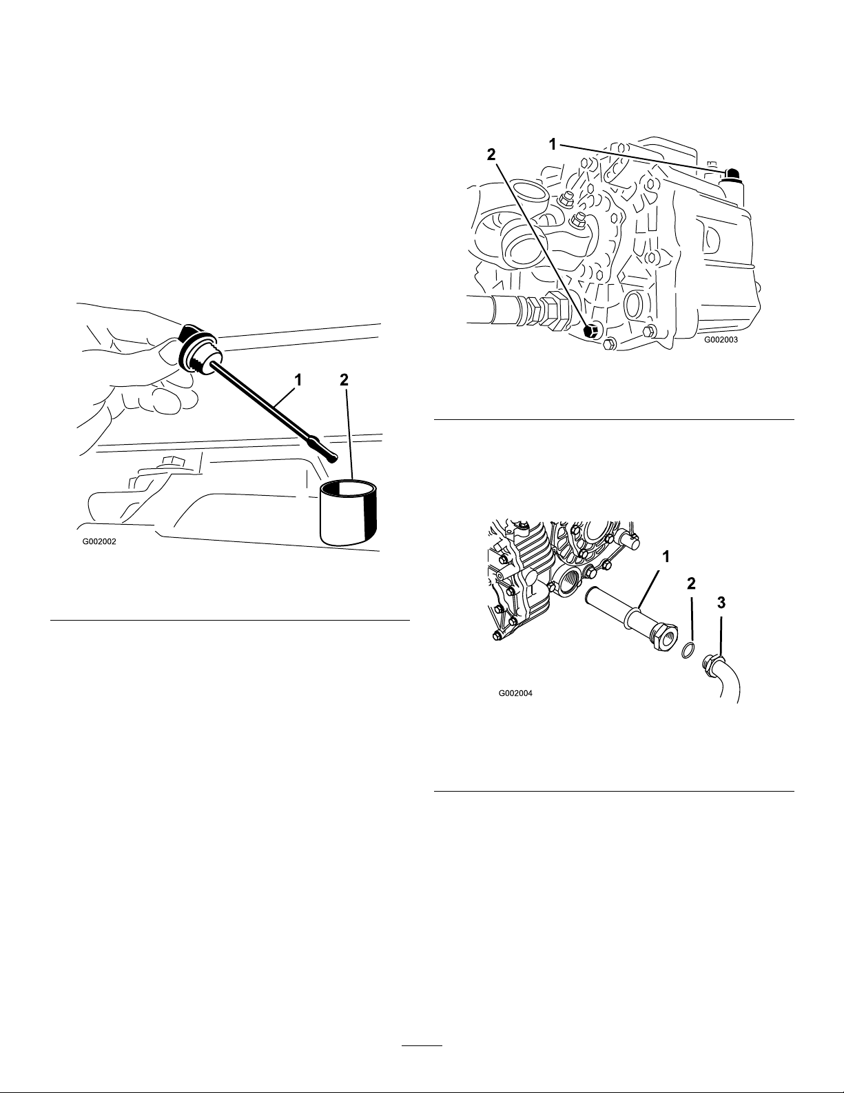
HydraulicSystem
2.Placeadrainpanunderthedrainplugofthe
reservoir.
Maintenance
Checkingthe
Transaxle/HydraulicFluid
ServiceInterval:Every200hours
1.Positionthesprayeronalevelsurface,setthe
parkingbrake,stopthepump,stoptheengine,
andremovetheignitionkey.
2.Removethetransaxledipstickandwipeitwitha
cleanrag(Figure38).
3.Removethedrainplugfromthesideofthe
reservoir,andletthehydraulicuidowintothe
drainpan(Figure39).
g002003
Figure39
1.Hydraulicdipstick2.Drainplug
4.Notetheorientationofthehydraulichoseand
90°ttingconnectedtothestrainer.
5.Removethehydraulichoseand90°tting
(Figure40).
Figure38
1.Dipstick2.Fillhole
Important:Beverycarefulnottogetdirtor
othercontaminantsintotheopeningwhen
checkingthetransmissionoil.
3.Insertthedipstickintothetubeandmakesure
thatitisseatedfully .Removethedipstickand
checktheoillevel.
4.Thetransaxleuidlevelshouldbeatthetop
oftheatportionofthedipstick.Ifitisnot,ll
thereservoirwiththeappropriateuid;referto
ChangingTransaxle/HydraulicFluid(page49).
5.Installthedipstickrmlyinplace.
Changing
Transaxle/HydraulicFluid
ServiceInterval:Every800hours/Yearly(whichever
comesrst)
1.Positionthesprayeronalevelsurface,setthe
parkingbrake,stopthepump,stoptheengine,
andremovetheignitionkey.
g002002
g002004
Figure40
1.Hydraulicstrainer
2.O-ring
6.Removethestrainerandcleanitbyback
ushingitwithacleandegreaser.
7.Allowthestrainertoairdry.
8.Installthestrainerwhentheoilisdraining.
9.Installthehydraulichoseand90°ttingtothe
strainer.
10.Installandtightenthedrainplug.
11.Fillthereservoirwithapproximately7L(7.5qt)
ofDexronIIlATF.
3.90°tting
49
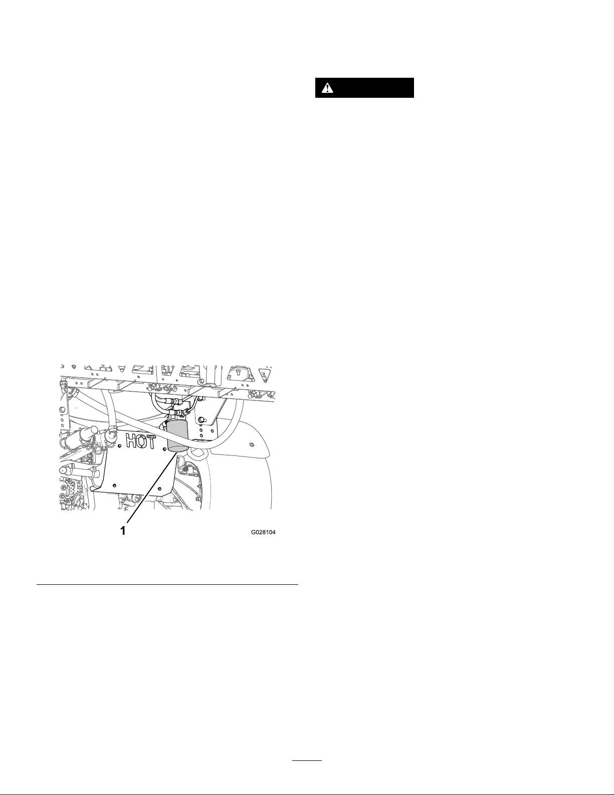
Important:Useonlythehydraulicuids
specied.Otheruidscouldcausesystem
damage.
12.Starttheengineanddrivethesprayertollthe
hydraulicsystem.
13.Checktheoillevelandreplenishit,ifrequired.
ReplacingtheHydraulic
Filter
ServiceInterval:Aftertherst8hours
Every800hours/Yearly(whichevercomesrst)
UsetheTororeplacementlter(PartNo.54-0110).
Important:Useofanyotherltermayvoidthe
warrantyonsomecomponents.
1.Positionthesprayeronalevelsurface,setthe
parkingbrake,stopthepump,stoptheengine,
andremovetheignitionkey.
2.Cleantheareaaroundtheltermountingarea.
3.Placeadrainpanunderthelter.
SpraySystem
Maintenance
WARNING
Chemicalsubstancesusedinthespray
systemmaybehazardousandtoxictoyou,
bystanders,animals,plants,soilsorother
property.
•Carefullyreadandfollowthechemical
warninglabelsandMaterialSafetyData
Sheets(MSDS)forallchemicalsusedand
protectyourselfaccordingtothechemical
manufacturer'srecommendations.For
example,useappropriatePersonal
ProtectiveEquipment(PPE),including
faceandeyeprotection,gloves,orother
equipmenttoguardagainstpersonal
contactwithchemicals.
•Keepinmindthattheremaybemorethan
onechemicalusedandinformationon
eachshouldbeassessed.
4.Removethelter(Figure41).
Figure41
1.Hydrauliclter
5.Lubricatethenewltergasket.
6.Ensurethattheltermountingareaisclean.
7.Screwthelteronuntilthegasketcontactsthe
mountingplate,thentightenthelterone-half
turn.
•Refusetooperateorworkonthesprayerif
thisinformationisnotavailable!
•Beforeworkingonaspraysystemmake
surethatthesystemhasbeentriple
rinsedandneutralizedaccordingto
therecommendationsofthechemical
manufacturer(s)andallofthevalveshave
beencycled3times.
•Verifythatthereisanadequatesupply
ofcleanwaterandsoapnearby,and
immediatelywashoffanychemicalsthat
contactyou.
g028104
InspectingtheHoses
ServiceInterval:Every200hours—Inspectallhoses
andconnectionsfordamageand
properattachment.
Examineeachhoseinthespraysystemforcracks,
leaksorotherdamage.Atthesametime,inspectthe
connectionsandttingsforsimilardamage.Replace
anyhosesandttingsifdamaged.
8.Starttheengineandletitrunforabout2minutes
topurgeairfromthesystem.
9.Stoptheengineandcheckthehydraulicoillevel
andforleaks.
50
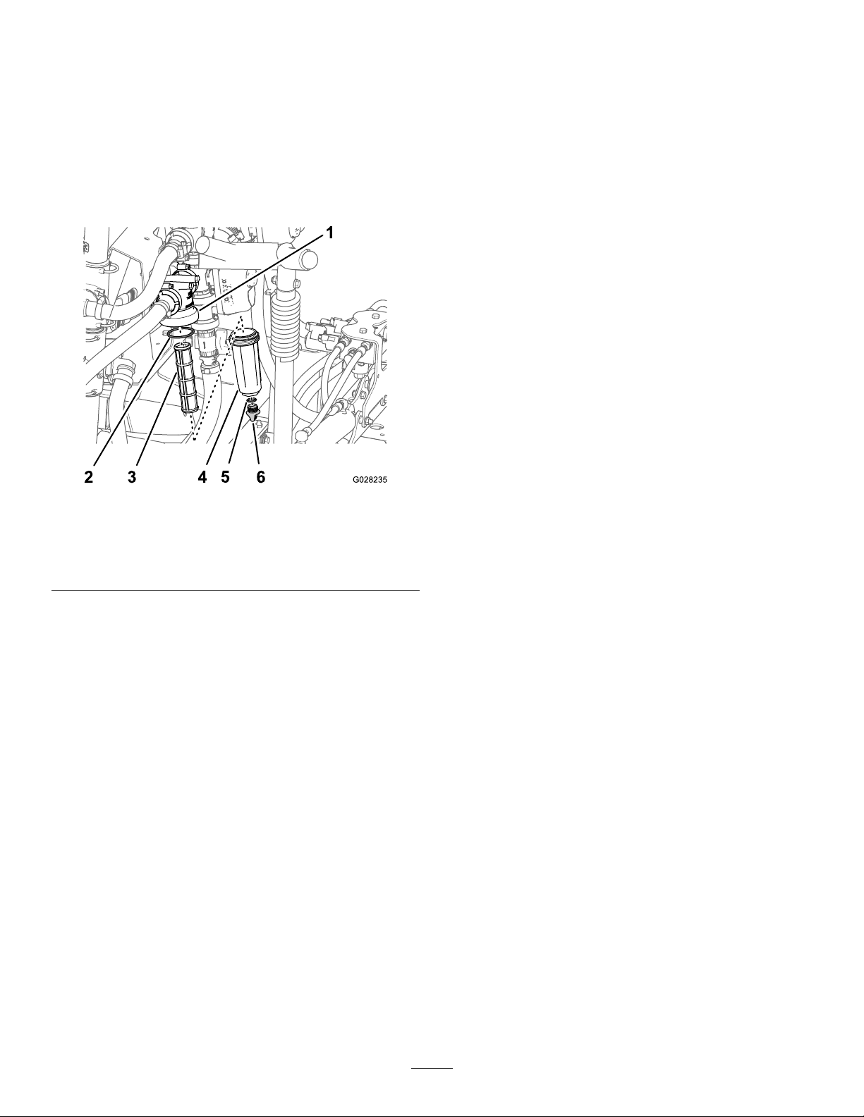
ChangingthePressure
Filter
9.Installtheplugintothebowlhandtight(Figure
42).
ServiceInterval:Every400hours
1.Movethemachinetoalevelsurface,shutoffthe
sprayerpump,shutofftheengine,andremove
thekeyfromthestarterswitch.
2.Alignadrainpanunderthepressurelter
(Figure42).
Figure42
InspectingthePump
ServiceInterval:Every400hours/Yearly(whichever
comesrst)—Inspectthepump
diaphragmsandreplaceif
necessary(seeanAuthorized
ToroServiceDistributor).
Every400hours/Y early(whichevercomes
rst)—Inspectthepumpcheckvalvesand
replaceifnecessary(seeanAuthorizedT oro
ServiceDistributor).
Note:Thefollowingmachinecomponentsare
consideredpartssubjecttoconsumptionthroughuse
unlessfounddefectiveandarenotcoveredbythe
warrantyassociatedwiththismachine.
HaveanAuthorizedT oroServiceDistributorcheck
followinginternalpumpcomponentsfordamage:
•Pumpdiaphragms
•Pumpcheckvalvesassemblies
g028235
Replaceanycomponents,ifnecessary.
1.Filterhead4.Bowl
2.O-ring(bowl)5.O-ring(drainplug)
3.Filterelement6.Drainplug
3.Rotatethedrainplugcounterclockwiseand
removeitfromthebowlofthepressurelter
(Figure42).
Note:Allowthebowltodraincompletely.
4.Rotatethebowlcounterclockwiseandremoveit
lterhead(Figure42).
5.Removetheoldpressurelterelement(Figure
42).
Note:Discardtheoldlter.
6.ChecktheO-ringforthedrainplug(located
insidethebowl)andtheO-ringforbowl(located
insidethelterhead)fordamageandwear
(Figure42).
Note:ReplaceanydamagedorwornO-rings
fortheplug,bowl,orboth.
7.Installthenewpressurelterelementintothe
lterhead(Figure42).
InspectingtheNylonPivot
Bushings
ServiceInterval:Every400hours/Yearly(whichever
comesrst)
1.Positionthesprayeronalevelsurface,setthe
parkingbrake,stopthepump,stoptheengine,
andremovetheignitionkey.
2.Extendtheboomstothespraypositionand
supporttheboomsusingstandsorstrapsfrom
alift.
3.Withtheweightoftheboomsupported,remove
theboltandnutsecuringthepivotpintothe
boomassembly(Figure43).
Note:Ensurethatthelterelementisrmly
seatedintothelterhead.
8.Installthebowlontothelterheadhandtight
(Figure42).
51

Figure43
1.Nylonbushing3.Bolt
2.Pivotpin
4.Removethepivotpin.
5.Removetheboomandpivotbracketassembly
fromthecenterframetoaccessthenylon
bushings.
6.Removeandinspectthenylonbushingsfrom
thefrontandbacksidesofthepivotbracket
(Figure43).
Note:Replaceanydamagedbushings.
7.Placeasmallamountofoilonthenylon
bushingsandinstallthemintopivotbracket.
8.Installtheboomandpivotbracketassemblyinto
thecenterframe,aligningtheopenings(Figure
43).
9.Installthepivotpinandsecureitwiththebolt
andnutremovedpreviously .
g022367
10.Repeattheprocedureforeachboom.
52

SprayerFlowDiagram
Figure44
g028078
53
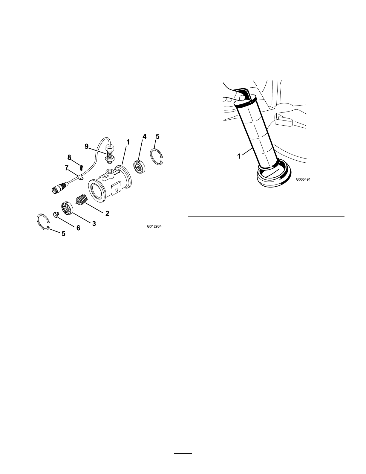
Cleaning
CleaningtheSuction
Strainer
CleaningtheFlowmeter
ServiceInterval:Every200hours/Yearly(whichever
comesrst)(moreoftenwhenusing
wettablepowders).
1.Thoroughlyrinseanddraintheentirespraying
system.
2.Removetheowmeterfromthesprayer,and
ushitwithcleanwater.
3.Removetheretainerringontheupstreamside
(Figure45).
ServiceInterval:Beforeeachuseordaily(more
oftenwhenusingwetablepowders).
1.Removetheretainerfromtheredttingattached
tothelargehoseonthetopofthetank.
g005491
Figure46
1.Suctionstrainer
Figure45
1.Modiedangedbody
2.Rotor/magnetassembly7.Cableclamp
3.Hub/bearingassembly
4.Hubassembly(with
keywayup)
5.Retainingring
4.Cleantheturbineandtheturbinehubtoremove
metallingsandanywettablepowders.
5.Inspecttheturbinebladesforwear.
6.Turbinestudassembly
8.Threadscrew
9.Sensorassembly
Note:Holdtheturbineinyourhandandspin
it.Itshouldspinfreelywithverylittledrag.Ifit
doesnot,replaceit.
6.Assembletheowmeter.
7.Usealow-pressureairjet(50kPaor5psi)to
ensurethattheturbinespinsfreely .Ifitdoes
not,loosenthehexstudonthebottomofthe
turbinehubby1/16ofaturnuntiltheturbine
spinsfreely.
2.Disconnectthehosefromthetank.
g012934
3.Pullthestraineroutofthehole.
4.Cleanthestrainerwithcleanrunningwater.
5.Replacethestrainer,seatingitfullyintothehole.
6.Connectthehosetothetopofthetankand
secureitwiththeretainer.
54
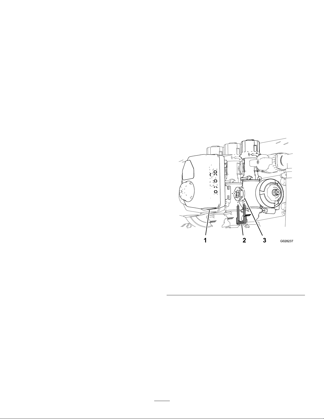
CleaningtheSprayer
Valves
•Tocleantheratecontrolvalve,refertothe
followingsections:
1.RemovingtheValveActuator(page55)
2.RemovingtheRateControlManifoldValve
(page56)
3.CleaningtheManifoldValve(page59)
4.AssemblingtheManifoldValve(page60)
RemovingtheValveActuator
1.Positionthesprayeronalevelsurface,setthe
parkingbrake,stopthepump,stoptheengine,
andremovethekeyfromthestarterswitch.
2.Removethe3-pinconnectorofthevalve
actuatorfromthe3socketelectricalconnector
ofthesprayerharness.
3.Removetheretainerthatsecurestheaactuator
tothemanifoldvalvefortheratecontrol,
agitation,masterboom,orboomsectionvalve
(Figure47).
5.InstallingtheRateControlManifoldV alve
(page61)
6.InstallingtheValveActuator(page64)
•Tocleantheagitationvalve;refertothefollowing
sections:
1.RemovingtheValveActuator(page55)
2.RemovingtheAgitationManifoldValve
(page56)
3.CleaningtheManifoldValve(page59)
4.AssemblingtheManifoldValve(page60)
5.InstallingtheAgitationManifoldValve(page
62)
6.InstallingtheValveActuator(page64)
•Tocleanthemasterboomvalve,refertothe
followingsections:
1.RemovingtheValveActuator(page55)
2.RemovingtheMasterBoomManifoldValve
(page57)
3.CleaningtheManifoldValve(page59)
4.AssemblingtheManifoldValve(page60)
Note:Squeezethe2legsoftheretainer
togetherwhilepushingitdown.
Note:Retaintheactuatorandretainerfor
installationinInstallingtheValveActuator(page
64).
g028237
Figure47
SectionValveActuatorshown(theagitationvalveactuator
issimilar)
5.InstallingtheMasterBoomManifoldValve
(page63)
6.InstallingtheValveActuator(page64)
•Tocleanthe3sectionvalves;refertothefollowing
sections:
1.RemovingtheValveActuator(page55)
2.RemovingtheSectionManifoldValve(page
58)
3.CleaningtheManifoldValve(page59)
4.AssemblingtheManifoldValve(page60)
5.InstallingtheSectionManifoldValve(page
63)
6.InstallingtheValveActuator(page64)
1.Valveactuator(section
valveshown)
2.Retainer
4.Removetheactuatorfromthemanifoldvalve.
55
3.Stemport
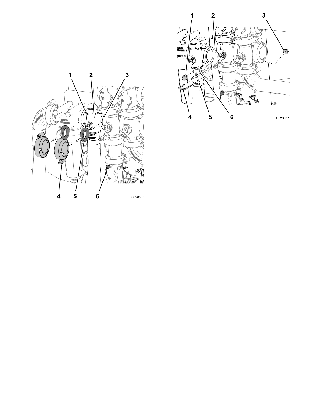
RemovingtheRateControl
ManifoldValve
1.Removeclampsandgasketsthatsecurethe
manifoldfortheratecontrolvalve(Figure48).
Note:Retaintheclamp(s)andgasket(s)for
installationinRemovingtheRateControl
ManifoldValve(page56).
Figure49
1.Flanged-headbolt4.Retainer
2.Valvemount
3.Flangedlocknut
5.Socket(outlettting)
6.Manifoldvalveassembly
3.Removethe2anged-headboltsand2anged
locknutsthatsecurestheratecontrolvalveto
thevalvemountandremovethevalvemanifold
fromthemachine(Figure49).
g028537
Figure48
1.Flange(pressurelter
head)
2.Manifold(ratecontrol
valve)
3.Flange(agitationvalve)6.3-pinconnector(valve
4.Clamp
5.Gasket
actuator—ratecontrol
valve)
2.Removetheretainerthatsecuretheoutlettting
tothemanifoldfortheratecontrolvalve(Figure
49).
g028536
Note:Ifnecessary ,loosenedthemounting
hardwareforthepressurelterheadtoease
removaloftheratecontrolvalve..
RemovingtheAgitationManifold
Valve
1.Removeclampsandgasketsthatsecurethe
manifoldfortheagitationvalve(Figure50)to
theagitationbypassvalve,ratecontrolvalve,
masterboomvalve,andadaptertting(agitation
throttlevalve).
Note:Retaintheclamp(s)andgasket(s)for
installationinInstallingtheAgitationManifold
Valve(page62).
56
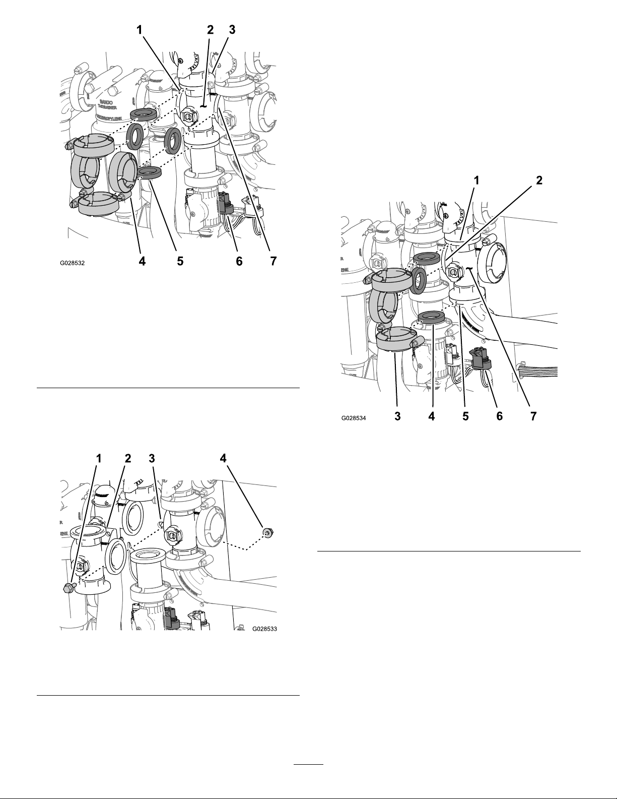
Figure50
RemovingtheMasterBoom
ManifoldValve
1.Removeclampsandgasketsthatsecurethe
manifoldforthemasterboomvalve(Figure52)
tothemasterboombypassvalve,agitation
valve,and90°angedelbow(attheendofthe
hosefortheowmeter).
Note:Retaintheclamp(s)andgasket(s)for
installationinInstallingtheMasterBoom
ManifoldValve(page63).
g028532
1.Flange(pressurelter
head)
2.Manifold(agitationvalve)6.3-pinconnector(valve
3.Flange(bypass
valve—agitationvalve)
4.Clamp
5.Gasket
actuator—agitationvalve)
7.Flange(masterboom
valve)
2.Removetheanged-headboltandanged
locknutthatsecurestheagitationvalvetothe
valvemountandremovethevalvemanifoldfrom
themachine(Figure51).
Figure52
1.Flange(bypass—master
boomvalve)
2.Flange(agitationvalve)6.3-pinconnector(valve
3.Clamp7.Manifold(masterboom
4.Gasket
5.90°angedelbow
actuator—masterboom
valve)
valve)
2.Removetheanged-headboltandanged
locknutthatsecuresthemasterboomvalveto
thevalvemountandremovethevalvemanifold
fromthemachine(Figure53).
g028534
Figure51
1.Flanged-headbolt3.Valvemount
2.Manifold(agitationvalve)
4.Flangedlocknut
g028533
57
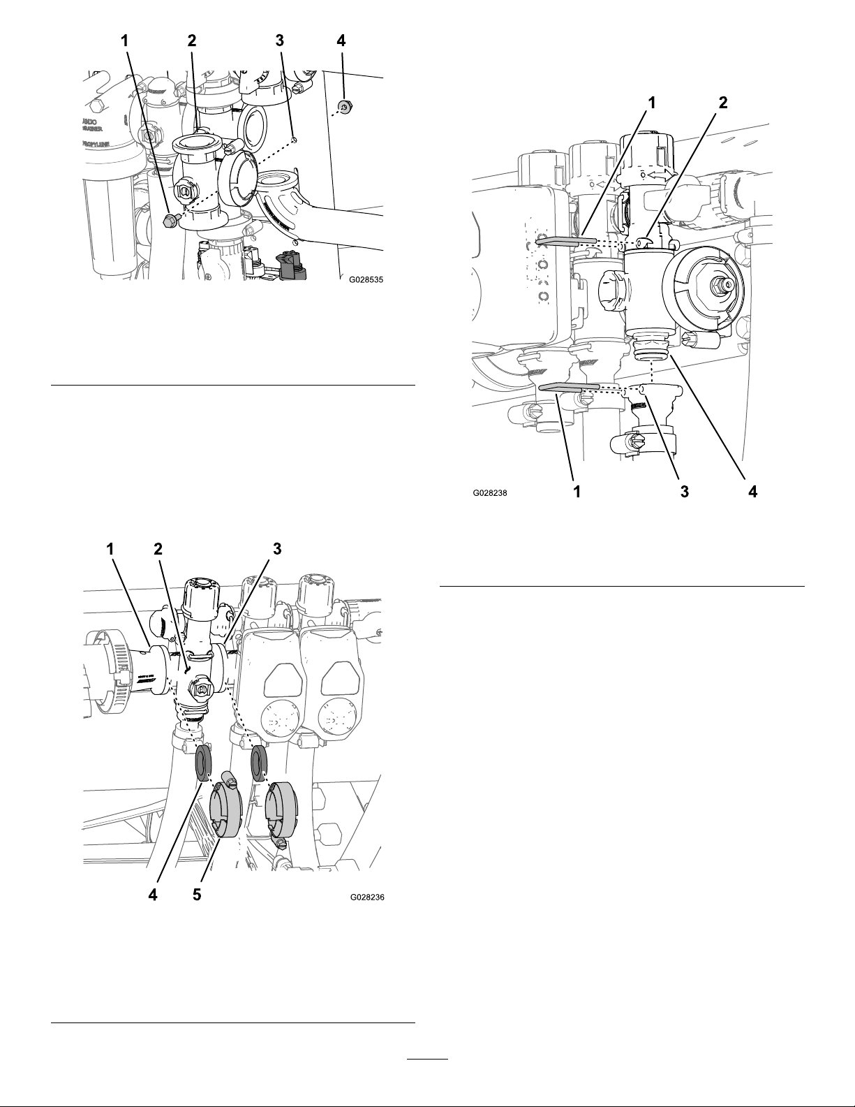
Figure53
1.Flanged-headbolt3.Valvemount
2.Manifold(masterboom
valve)
RemovingtheSectionManifold
2.Removetheretainersthatsecuretheoutlet
ttingtothesectionvalvemanifoldandthevalve
manifoldtothebypasstting(Figure55).
g028535
4.Flangedlocknut
Valve
1.Removeclampsandgasketsthatsecurethe
manifoldforthesectionvalve(Figure54)tothe
adjacentsectionvalve(ifleftsectionvalve,and
thereducercoupling).
Figure55
1.Retainer
2.Socket(bypasstting)4.Manifoldvalveassembly
3.Socket(outlettting)
3.Fortheleftorrightboomsectionvalves,remove
theanged-headboltsandangedlocknutsthat
securesthesectionvalve(s)tothevalvemount
andremovethevalvemanifold(s)fromthe
machine;forthecentersectionvalve,remove
thesectionvalvemanifoldfromthemachine
(Figure56).
g028238
Figure54
1.Flange(reducercoupling)4.Gasket
2.Manifold(sectionvalve)
3.Flange(adjacentsection
valve)
g028236
5.Flangeclamp
58
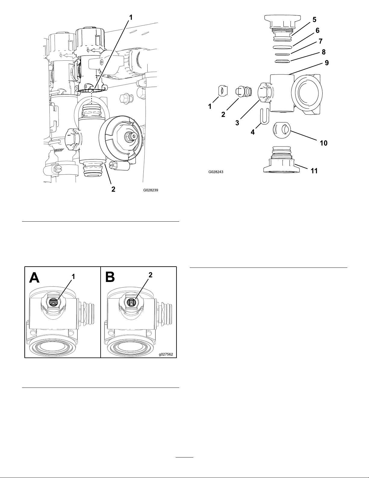
Figure56
1.Bypasstting2.Sectionvalvemanifold
CleaningtheManifoldValve
1.Positionthevalvestemsothatitisintheclosed
position(BofFigure57).
g028243
Figure58
g028239
1.Stemretainer7.BackseatingO-ring(0.676
2.Valvestem8.V alveseatring
3.Stemport9.Mainfoldbody
4.Stemcaptureretainer
5.Endcaptting11.Endcapttingassembly
6.EndcapsealO-ring(0.796
inch/0.139inch)
AgitationValveManifold
inch/0.07inch)
10.Ballvalve
Figure57
1.Valveopen2.Valveclosed
2.Removethe2endcapttingassemblyfrom
eachendofthemanifoldbody(Figure58and
Figure59).
g027562
59

Figure59
SectionValveManifold
1.Valvestemseat
2.Valvestemassembly
3.Stemport
4.Stemretainer10.Mainfoldbody
5.OutletttingO-ring(0.737
inch/0.103inch)
6.Endcaptting12.Endcapttingassembly
7.EndcapO-ring(0.796inch
/0.139inch)
8.BackseatingO-ring(0.676
inch/0.07inch)
9.Ballseat
11.Ballvalve
AssemblingtheManifoldValve
1.ChecktheconditionoftheoutletttingO-rings
(sectionvalvemanifoldonly),endcapO-rings,
backseatingO-rings,ballseatfordamageor
wear(Figure58andFigure59).
Note:ReplaceanydamagedorwornO-rings
orseats.
2.Applygreasetothevalvestemandinsertitinto
thevalvestemseat(Figure58andFigure59).
3.Installthevalvestemandseatintothemanifold
andsecurethestemandseatwiththestem
retainer(Figure58andFigure59).
4.EnsurethatthebackseatingO-ringandtheball
seatarealignedandseatedintotheendcap
tting(Figure58andFigure59)
5.Installtheendcapttingassemblyontothe
manifoldbodyuntiltheangeoftheendcap
ttingtouchesthemanifoldbody(Figure58
andFigure59),thenturntheendcapttingan
g028240
additional1/8to1/4turn;torquethettingto225
to282N-cm(20to25in-lbs).
Note:Usecautionsoasnottodamagetheend
ofthetting.
6.Inserttheballintothevalvebody(Figure60).
Note:Thevalvestemshouldtinsidetheball
driveslot.Ifthevalvestemdoesnott,adjust
thepositionoftheball(Figure60).
3.Turnthevalvestemsothattheballisinthe
openposition(AofFigure57).
Note:Thevalvestemwillbeparallelwiththe
valveowandtheballwillslideout.
4.Removethestemretainerfromtheslotsinthe
stemportinthemanifold(Figure58andFigure
59).
5.Removethestemretainerandvalvestemseat
fromthemanifold(Figure58andFigure59).
6.Reachintothemanifoldbodyandremovethe
valvestemassembly(Figure58andFigure59).
7.Cleantheinsideofthemanifoldandexterior
oftheballvalve,valvestemassembly,stem
capture,andendttings.
g027565
Figure60
7.Turnthevalvestemassemblysothatthevalve
isclosed(BofFigure57)
8.Repeatsteps4and5fortheotherendcaptting
assembly.
60

InstallingtheRateControl
ManifoldValve
1.Aligna1gasketbetweentheangesoftherate
controlvalvemanifoldandthepressurelter
head(AofFigure61).
Note:Ifneeded,loosenthemountinghardware
forthepressurelterheadasneededtoprovide
clearance.
4.Assembletheratecontrolvalvemanifold,
gasket,andagitationvalvemanifoldwitha
clamptightenedhandtight(AofFigure61).
5.Assembletheratecontrolvalvetothevalve
mountwiththe2anged-headboltsand2
angedlocknuts(AofFigure61)thatyou
removedinstep3ofRemovingtheRateControl
ManifoldV alve(page56)andtorquethenutand
boltto1017to1243N-cm(90to110in-lb).
6.Assembletheoutletttingontothelowerendcap
ttingofthemanifoldvalve(BofFigure61).
7.Securetheendcapttingtotheoutletttingby
insertingaretainerintothesocketoftheoutlet
tting(BofFigure61).
8.Ifyouloosenedthemountinghardwareforthe
pressurelterhead,tightenthenutandboltto
1978to2542N-cm(175to225in-lb).
Figure61
1.Locknut
2.Valvemount
3.Flange
(agitation
valve)
4.Flanged-head
bolt
5.Gasket9.Manifoldvalve
6.Clamp10.Socket(outlet
7.Flange
(pressurelter
head)
8.Flange(rate
controlvalve)
assembly
tting)
11.Retainer
2.Assembletheratecontrolvalvemanifold,
gasket,andpressurelterheadwithaclamp
tightenedhandtight(AofFigure61).
3.Aligna1gasketbetweentheangesoftherate
controlvalveandtheagitationvalvemanifold(A
ofFigure61)
g028538
61
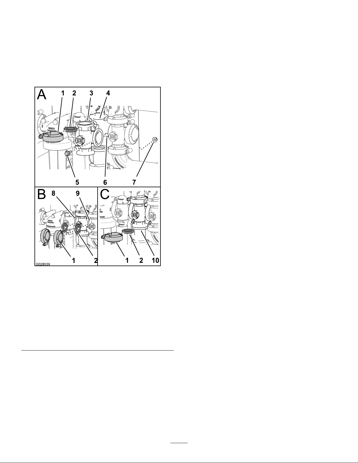
InstallingtheAgitationManifold
Valve
1.Aligntheangeoftheagitationvalvemanifold,
1gasket,andtheangeoftheagitationbypass
valve(AofFigure62).
Note:Ifneeded,loosenthemountinghardware
forthemasterboomvalveasneededtoprovide
clearance.
5.Aligna1gasketbetweentheangesofthe
agitationvalvemanifoldandthemasterboom
valve(BofFigure62).
6.Assembletheagitationvalvemanifold,gasket,
andmasterboomvalvewithaclamptightened
handtight(BofFigure62).
7.Aligna1gasketbetweentheangesofthe
agitationvalvemanifoldandtheadaptertting
fortheagitationthrottlevalve(CofFigure62).
8.Assembletheagitationvalvemanifold,gasket,
andadapterttingwithaclamptightenedhand
tight(CofFigure62).
9.Assembletheagitationvalvetothevalvemount
withtheanged-headboltandangedlocknut
thatyouremovedinstep2ofRemovingthe
AgitationManifoldValve(page56)andtorque
thenutandboltto1017to1243N-cm(90to
110in-lb).
10.Ifyouloosenedthemountinghardwareforthe
masterboomvalve,tightenthenutandboltto
1978to2542N-cm(175to225in-lb).
Figure62
1.Flangeclamp6.Valvemount
2.Gasket
3.Manifold(agitationvalve)8.Flange(ratecontrolvalve)
4.Flange
(manifold—agitation
bypassvalve)
5.Flanged-headbolt
7.Flangedlocknut
9.Flange(masterboom
valve)
10.Flange(adapter
tting—agitationthrottle
valve)
2.Assembletheagitationbypassvalve,gasket,
andagitationvalvemanifoldwithaclamp
tightenedhandtight(AofFigure62).
3.Aligna1gasketbetweentheangesoftherate
controlvalveandtheagitationvalvemanifold
(BofFigure62).
4.Assembletheratecontrolvalve,gasket,and
agitationvalvemanifoldwithaclamptightened
handtight(BofFigure62).
g028539
62
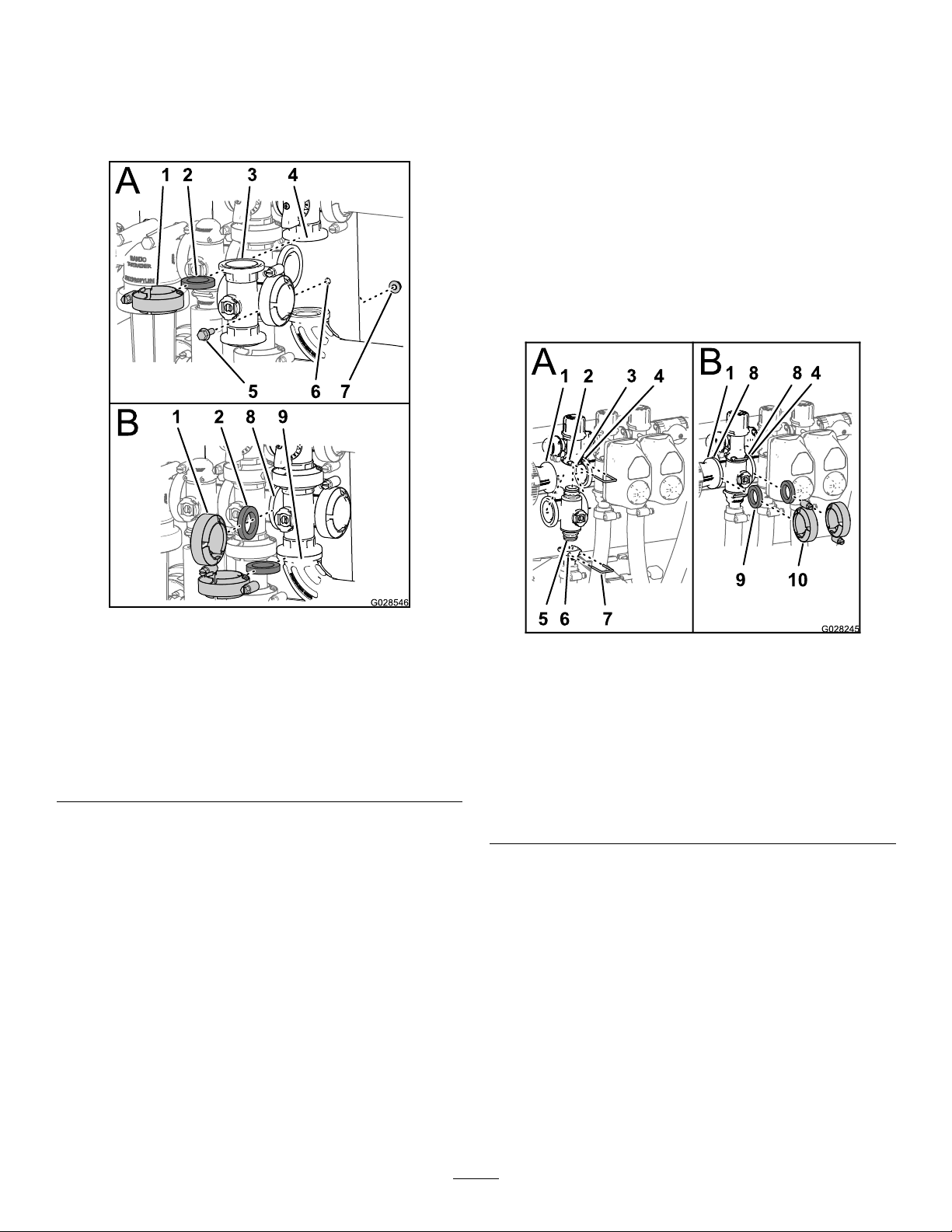
InstallingtheMasterBoom
ManifoldValve
1.Aligntheangeofthemasterboomvalve
manifold,1gasket,andtheangeofthemaster
boombypassvalve(AofFigure63).
7.Assembletheagitationvalvetothevalvemount
withtheanged-headboltandangedlocknut
thatyouremovedinstep2ofInstallingthe
MasterBoomManifoldValve(page63)and
torquethenutandboltto1017to1243N-cm
(90to110in-lb).
InstallingtheSectionManifold
Valve
1.Inserttheupperendcapttingofthemanifold
valveintothebypasstting(AofFigure64).
Note:Ifneeded,loosenthemountinghardware
forthebypassttingasneededtoprovide
clearance.
Figure63
1.Flangeclamp6.Valvemount
2.Gasket
3.Manifold(masterboom
valve)
4.Flange(bypass—master
boomvalve)
5.Flanged-headbolt
7.Flangedlocknut
8.Flange(agitationvalve)
9.90°angedelbow
2.Assemblethemasterboomvalvemanifold,
gasket,andmasterboombypassvalvewitha
clamptightenedhandtight(AofFigure63).
3.Aligntheangeofthemasterboomvalve
manifold,1gasket,andtheagitationvalve
manifold(BofFigure63).
4.Assemblethemasterboomvalvemanifold,
gasket,andagitationvalvemanifoldwitha
clamptightenedhandtight(BofFigure63)
5.Aligntheangeofthemasterboomvalve
manifold,1gasket,andthe90°angedelbow
(attheendofthehosefortheowmeter;refer
toBofFigure63).
6.Assemblethemasterboomvalvemanifold,
gasket,and90°angedelbowwithaclamp
tightenedhandtight(BofFigure63).
g028546
g028245
Figure64
1.Flange(reducercoupling)6.Socket(outlettting)
2.Socket(bypasstting)
3.Bypasstting8.Flange(manifold—section
4.Flange(adjacent
manifold—agitationvalve)
5.Endcaptting(manifold
valveassembly)
7.Retainer
valve)
9.Gasket
10.Flangeclamp
2.Securetheendcapttingtothebypassttingby
insertingaretainerintothesocketofthebypass
tting(AofFigure64).
3.Assembletheoutletttingontothelowerendcap
ttingofthemanifoldvalve(AofFigure64).
4.Securetheendcapttingtotheoutletttingby
insertingaretainerintothesocketoftheoutlet
tting(AofFigure64)
5.Aligna1gasketbetweentheangesofthe
reducercouplingandthesectionvalvemanifold
(BofFigure64).
6.Assemblethereducercoupling,gasket,and
sectionvalvemanifoldwithaclamptightened
handtight(BofFigure64).
63

7.Ifinstallingthe2leftmostsectionvalves,aligna
1gasketbetweentheangesofthe2adjacent
sectionvalvemanifolds(BofFigure64).
8.Assembletheand2adjacentsectionvalve
manifoldsandgasketwithaclamptightened
handtight(BofFigure64).
9.Fortheleftorrightboomsectionvalves,
assemblethevalvestothevalvemountwith
theanged-headboltandangedlocknutthat
youremovedinstep3ofRemovingtheSection
ManifoldValve(page58)andtorquethenuts
andboltsto1017to1243N-cm(90to110in-lb).
10.Ifyouloosenedthemountinghardwareforthe
bypasstting,tightenthenutandboltto1017to
1243N-cm(90to110in-lb).
InstallingtheValveActuator
1.Aligntheactuatortothemanifoldvalveand
(Figure47).
2.Securetheactuatorandvalvewiththeretainer
thatyouremovedinstep3ofRemovingthe
ValveActuator(page55).
3.Connectthe3-pinconnectorofthevalve
actuatorharnesstothe3-socketconnectorof
thewiringharnessofthesprayer
Storage
1.Positionthesprayeronalevelsurface,setthe
parkingbrake,stopthepump,stoptheengine,
andremovetheignitionkey.
2.Cleandirtandgrimefromtheentiremachine,
includingtheoutsideoftheenginecylinderhead
nsandblowerhousing.
Important:Youcanwashthemachine
withmilddetergentandwater.Donotuse
high-pressurewatertowashthemachine.
Pressurewashingmaydamagetheelectrical
systemorwashawaynecessarygreaseat
frictionpoints.Avoidexcessiveuseofwater,
especiallynearthecontrolpanel,lights,
engine,andthebattery.
3.Cleanthespraysystem;refertotheCleaning
theSprayer(page29).
4.Cleanthepistonsinthevalveassembly;referto
CleaningtheSprayerValves(page55).
5.Conditionthesprayersystemasfollows:
A.Drainthefreshwatertank.
B.Drainthespraysystemascompletelyas
possible.
C.Preparerustinhibiting,non-alcohol
based,RVantifreezesolutionperthe
manufacturer'sinstructions.
D.AddtheRVantifreezesolutiontothefresh
watertankandthesprayertank.
E.Runthesprayerpumpforafewminutes
tocirculatetheRVantifreezethroughout
thesprayersystemandanyinstalledspray
accessories.
F.Drainthefreshwatertankandspraysystem
ascompletelyaspossible.
6.Usetheboomliftswitchestoraisethebooms.
Raisetheboomsuntiltheyhavemoved
completelyintoboomtransportcradleforming
the“X”transportpositionandtheboomcylinders
arefullyretracted.Makesuretheboom
cylindersarefullyretractedtopreventactuator
roddamage.
7.Inspectthebrakes;refertoInspectingthe
Brakes(page48).
8.Servicetheaircleaner;refertoServicingtheAir
Cleaner(page40).
9.Greasethesprayer;refertotheLubrication
(page39).
10.Changethecrankcaseoil;refertoChangingthe
EngineOil(page42).
11.Checkthetirepressure;refertoCheckingthe
TirePressure(page23).
64

12.Forstorageover30days,preparethefuel
systemasfollows:
18.Checkandtightenallbolts,nuts,andscrews.
Repairorreplaceanypartthatisdamaged.
A.Addapetroleumbased
stabilizer/conditionertofuelinthe
tank.
Followmixinginstructionsfromstabilizer
manufacturer.Donotuseanalcoholbased
stabilizer(ethanolormethanol).
Note:Afuelstabilizer/conditionerismost
effectivewhenmixedwithfreshgasoline
andusedatalltimes.
B.Runtheenginetodistributeconditionedfuel
throughthefuelsystem(5minutes).
C.Stoptheengine,allowittocool,anddrain
thefueltank.
D.Restarttheengineandrunituntilitstops.
E.Choketheengine.
F.Startandruntheengineuntilitwillnotstart
again.
G.Disposeoffuelproperly.Recycleasper
localcodes.
Important:Donotstore
stabilizer/conditionedgasolineover90
days
19.Checktheconditionofallsprayhoses,replacing
anythataredamagedorworn.
20.Tightenallhosettings.
21.Paintallscratchedorbaremetalsurfaces.Paint
isavailablefromyourAuthorizedServiceDealer.
22.Storethemachineinaclean,drygarageor
storagearea.
23.Removetheignitionkeyandputitinasafe
placeoutofthereachofchildren.
24.Coverthemachinetoprotectitandkeepitclean.
13.Removethesparkplugsandchecktheir
condition;refertoRemovingtheSparkPlug
(page43).
14.Withthesparkplugsremovedfromtheengine,
pourtwotablespoonsofengineoilintothespark
plughole.
15.Usetheelectricstartertocranktheengineand
distributetheoilinsidethecylinder.
16.Installthesparkplugsandtightento
recommendedtorque;refertoInstallingthe
SparkPlugs(page43).
Note:Donotinstallthewireonthespark
plug(s).
17.Removethebatteryfromthechassis,check
theelectrolytelevel,andchargeitfully;referto
ServicingtheBattery(page45).
Note:Donotconnectthebatterycablestothe
batterypostsduringstorage.
Important:Thebatterymustbefully
chargedtopreventitfromfreezingandbeing
damagedattemperaturesbelow0°C(32°F).
Afullychargedbatterymaintainsitscharge
forabout50daysattemperatureslowerthan
4°C(40°F).Ifthetemperatureswillbeabove
4°C(40°F),checkthewaterlevelinthe
batteryandchargeitevery30days.
65

Troubleshooting
TroubleshootingtheEngineandVehicle
Problem
Thestarterdoesnotcrank.
Theenginecranks,butwillnotstart.
Theenginestarts,butdoesnotkeep
running.
PossibleCauseCorrectiveAction
1.Therangeselectorisinagearother
thanNeutral.
2.Theelectricalconnectionsare
corrodedorloose.
3.Afuseisblownorloose.3.Correctorreplacefuse.
4.Thebatteryisdischarged.
5.Thesafetyinterlocksystemis
malfunctioning.
6.Astarterorstartersolenoidisbroken.
7.Theinternalenginecomponentshave
seized.
1.Thefueltankisempty.1.Fillthetankwithfreshfuel.
2.Dirt,water,orstalefuelisinthefuel
system.
3.Thefuellineisclogged.3.Cleanorreplacethefuelsystem.
4.Thesparkplugleadisdisconnected.4.Reconnectthesparkplug.
5.Asparkplugisdamagedordirty .5.Replacethesparkplug.
6.Thekillrelayisnotenergized.
7.Theignitionisbroken.
1.Thefueltankventisrestricted.1.Replacethefuelcap.
2.Dirtorwaterisinthefuelsystem.
3.Thefuellterisclogged.3.Replacethefuellter.
4.Afuseisblownorloose.4.Correctorreplacethefuse.
5.Thefuelpumpisbroken.
6.Thecarburetorisbroken.
7.Thereareloosewiresorpoor
connections.
8.Thecylinderheadgasketisbroken.
1.Pressthebrakepedalandmovethe
rangeselectortotheNeutralposition.
2.Checktheelectricalconnectionsfor
goodcontact.
4.Chargeorreplacethebattery.
5.ContactyourAuthorizedService
Dealer.
6.ContactyourAuthorizedService
Dealer.
7.ContactyourAuthorizedService
Dealer.
2.Drainandushthefuelsystem;add
freshfuel.
6.ContactyourAuthorizedService
Dealer.
7.ContactyourAuthorizedService
Dealer.
2.Drainandushthefuelsystem;add
freshfuel.
5.ContactyourAuthorizedService
Dealer.
6.ContactyourAuthorizedService
Dealer.
7.Checkandtightenwireconnections.
8.ContactyourAuthorizedService
Dealer.
Theengineruns,butknocksormisses.
1.Dirt,water,orstalefuelisinthefuel
system.
2.Asparkplugleadisloose.2.Reconnectthesparkpluglead.
3.Asparkplugisbroken.3.Replacethesparkplug.
4.Thereareloosewiresorpoor
connections.
5.Theengineisoverheating.
1.Drainandushthefuelsystem;add
freshfuel.
4.Checkandtightenwireconnections.
5.
See“Theengineoverheats”below.
66

Problem
PossibleCauseCorrectiveAction
Theenginewillnotidle.
Theengineoverheats.
Theenginelosespower.
1.Thefueltankventisrestricted.1.Replacethefuelcap.
2.Dirt,water,orstalefuelisinthefuel
system.
3.Asparkplugisdamagedorbroken.3.Replacethesparkplug.
4.Carburetoridlepassagesareplugged.4.ContactyourAuthorizedService
5.Theidlespeedadjustingscrewis
incorrectlyset.
6.Thefuelpumpisbroken.6.ContactyourAuthorizedService
7.Thereislowcompression.
8.Theaircleanerelementisdirty .
1.Thecrankcaseoillevelisincorrect.
2.Thereisexcessiveloading.2.Reducetheload;uselowerground
3.Theairintakescreensaredirty .
4.Thecoolingnsandairpassages
undertheengineblowerhousing
and/ortherotatingairintakescreen
areplugged.
5.Thefuelmixtureislean.5.ContactyourAuthorizedService
1.Thecrankcaseoillevelisincorrect.
2.Theaircleanerelementisdirty .
3.Dirt,water,orstalefuelisinthefuel
system.
4.Theengineisoverheated.
5.Asparkplugisdamagedordirty .5.Replacethesparkplug.
6.Theventholeinthefueltankvent
ttingisplugged.
7.Thereislowcompression.
2.Drainandushthefuelsystem;add
freshfuel.
Dealer.
5.ContactyourAuthorizedService
Dealer.
Dealer.
7.ContactyourAuthorizedService
Dealer.
8.Cleanorreplacetheelement.
1.Fillordraintothefullmark.
speed.
3.Cleanwitheveryuse.
4.Cleanwitheveryuse.
Dealer.
1.Fillordraintothefullmark.
2.Cleanorreplace.
3.Drainandushthefuelsystem;add
freshfuel.
4.SeeEngineOverheats.
6.Replacethefuelcap.
7.ContactyourAuthorizedService
Dealer.
Themachinewillnotoperateorissluggish
ineitherdirectionbecausetheengine
bogsdownorstalls.
Themachinewillnotoperateineither
direction.
1.Theenginemountingboltsareloose.1.Tightentheenginemountingbolts. Thereisabnormalvibrationornoise.
2.Thereisaproblemwiththeengine.
1.Theparkingbrakeisset.1.Releasetheparkingbrake.
1.TherangeselectorisintheNeutral
position.
2.Theparkingbrakewasnotreleasedor
theparkingbrakeisnotreleasing.
3.Thetransmissionisbroken.
4.Thecontrollinkageneedsadjustment
orreplacement.
5.Thedriveshaftorwheelhubkeyhas
beendamaged.
2.ContactyourAuthorizedService
Dealer.
1.Pressthebrakeandshifttherange
selectorintoagear.
2.Releasetheparkingbrakeorcheck
thelinkage.
3.
ContactyourAuthorizedService
Dealer.
4.ContactyourAuthorizedService
Dealer.
5.ContactyourAuthorizedService
Dealer.
67

TroubleshootingtheSpraySystem
Problem
Aboomsectiondoesnotspray.
Aboomsectiondoesnotturnoff.
Aboomvalveisleaking.1.Asealiswornordamaged.1.Disassemblethevalveandreplace
Apressuredropoccurswhenyouturnon
aboom.
1.Theelectricalconnectionontheboom
valveisdirtyordisconnected.
2.Thereisablownfuse.2.Checkthefusesandreplacethemas
3.Thereisapinchedhose.3.Repairorreplacethehose.
4.Aboom-sectionbypassisimproperly
adjusted.
5.Therearedamagedboomvalve.
6.Theelectricalsystemisdamaged.
1.Theboom-sectionvalveisdamaged.1.Disassembletheboom-sectionvalve;
1.Theboombypassisimproperly
adjusted.
2.Thereisanobstructionintheboom
valvebody .
3.Anozzlelterisdamagedorclogged.
PossibleCauseCorrectiveAction
1.Turnthevalveoffmanually .Disconnect
theelectricalconnectoronthevalve
andcleanallleads,thenreconnectit.
necessary.
4.Adjusttheboom-sectionbypass.
5.ContactyourAuthorizedService
Dealer.
6.ContactyourAuthorizedService
Dealer.
refertothesectionCleaningthe
SprayerValves.Inspectalloftheparts
andreplaceanythataredamaged.
thesealsusingtheValveRepair
Kit;contactyourAuthorizedService
Dealer.
1.Adjusttheboombypass.
2.Removetheinletandoutlet
connectionstotheboomvalve
andremoveanyobstructions.
3.Removeandinspectallnozzles.
68

Notes:

Notes:

InternationalDistributorList
Distributor:
AgrolancKft
BalamaPrimaEngineeringEquip.HongKong85221552163
B-RayCorporation
CascoSalesCompany
CeresS.A.CostaRica
CSSCTurfEquipment(pvt)Ltd.SriLanka
CyrilJohnston&Co.
CyrilJohnston&Co.RepublicofIreland
EquiverMexico525553995444ParklandProductsLtd.NewZealand6433493760
FemcoS.A.Guatemala
ForGarderOU
G.Y .K.CompanyLtd.
GeomechanikiofAthensGreece
GolfinternationalTurizm
GuandongGoldenStarChina
HakoGroundandGardenSweden
HakoGroundandGarden
HayterLimited(U.K.)
HydroturfInt.CoDubai
HydroturfEgyptLLC
IrrimacPortugal351212388260T oroEuropeNVBelgium3214562960
IrrigationProductsInt'lPvtLtd.India0091442449
JeanHeybroekb.v.Netherlands31306394611VictusEmakPoland48618238369
Country:
Hungary3627539640
Korea82325512076
PuertoRico7877888383
NorthernIreland442890813121
Estonia3723846060
Japan81726325861
Turkey902163365993Riversa
Norway4722907760
UnitedKingdom441279723444
UnitedArabEmirates97143479479T-MarktLogisticsLtd.Hungary3626525500
Egypt2025194308ToroAustraliaAustralia61395807355
PhoneNumber:Distributor:
5062391138
94112746100
442890813121
5024423277
30109350054
862087651338
4635100000
4387
Country:
MaquiverS.A.Colombia
MaruyamaMfg.Co.Inc.
Mountelda.s.CzechRepublic
Mountelda.s.Slovakia
MunditolS.A.
NormaGarden
OslingerTurfEquipmentSA
OyHakoGroundandGarden
Ab
Perfetto
PratoverdeSRL.
Prochaska&Cie
RTCohen2004Ltd.
LelyTurfcare
SolvertS.A.S.
SpyprosStavrinidesLimitedCyprus
SurgeSystemsIndiaLimited
ValtechMorocco21253766
Japan81332522285
Argentina541 14821
Russia74954116120
Ecuador59342396970
Finland35898700733
Poland48618208416
Italy390499128
Austria4312785100
Israel97298617979
Spain
Denmark4566109200
France331308177
India911292299901
Phone
Number:
5712364079
420255704
220
420255704
220
9999
128
34952837500
00
35722434131
3636
EuropeanPrivacyNotice
TheInformationT oroCollects
ToroWarrantyCompany(Toro)respectsyourprivacy.Inordertoprocessyourwarrantyclaimandcontactyouintheeventofaproductrecall,weaskyou
tosharecertainpersonalinformationwithus,eitherdirectlyorthroughyourlocalTorocompanyordealer.
TheT orowarrantysystemishostedonserverslocatedwithintheUnitedStateswhereprivacylawmaynotprovidethesameprotectionasapplies
inyourcountry.
BYSHARINGYOURPERSONALINFORMATIONWITHUS,YOUARECONSENTINGTOTHEPROCESSINGOFYOURPERSONALINFORMA TION
ASDESCRIBEDINTHISPRIV ACYNOTICE.
TheWayT oroUsesInformation
Toromayuseyourpersonalinformationtoprocesswarrantyclaims,tocontactyouintheeventofaproductrecallandforanyotherpurposewhichwetell
youabout.ToromayshareyourinformationwithToro'safliates,dealersorotherbusinesspartnersinconnectionwithanyoftheseactivities.Wewillnot
sellyourpersonalinformationtoanyothercompany.Wereservetherighttodisclosepersonalinformationinordertocomplywithapplicablelawsand
withrequestsbytheappropriateauthorities,tooperateoursystemsproperlyorforourownprotectionorthatofotherusers.
RetentionofyourPersonalInformation
Wewillkeepyourpersonalinformationaslongasweneeditforthepurposesforwhichitwasoriginallycollectedorforotherlegitimatepurposes
(suchasregulatorycompliance),orasrequiredbyapplicablelaw .
Toro'sCommitmenttoSecurityofYourPersonalInformation
Wetakereasonableprecautionsinordertoprotectthesecurityofyourpersonalinformation.Wealsotakestepstomaintaintheaccuracyandcurrent
statusofpersonalinformation.
AccessandCorrectionofyourPersonalInformation
Ifyouwouldliketorevieworcorrectyourpersonalinformation,pleasecontactusbyemailatlegal@toro.com.
AustralianConsumerLaw
AustraliancustomerswillnddetailsrelatingtotheAustralianConsumerLaweitherinsidetheboxoratyourlocalT oroDealer.
374-0269RevH

ToroGeneralCommercialProductWarranty
ATwo-YearLimitedWarranty
ConditionsandProductsCovered
TheToroCompanyanditsafliate,T oroWarrantyCompany ,pursuant
toanagreementbetweenthem,jointlywarrantyourT oroCommercial
product(“Product”)tobefreefromdefectsinmaterialsorworkmanship
fortwoyearsor1500operationalhours*,whicheveroccursrst.This
warrantyisapplicabletoallproductswiththeexceptionofAerators
(refertoseparatewarrantystatementsfortheseproducts).Wherea
warrantableconditionexists,wewillrepairtheProductatnocosttoyou
includingdiagnostics,labor,parts,andtransportation.Thiswarranty
beginsonthedatetheProductisdeliveredtotheoriginalretailpurchaser.
*Productequippedwithanhourmeter.
InstructionsforObtainingWarrantyService
YouareresponsiblefornotifyingtheCommercialProductsDistributoror
AuthorizedCommercialProductsDealerfromwhomyoupurchasedthe
Productassoonasyoubelieveawarrantableconditionexists.Ifyouneed
helplocatingaCommercialProductsDistributororAuthorizedDealer,or
ifyouhavequestionsregardingyourwarrantyrightsorresponsibilities,
youmaycontactusat:
ToroCommercialProductsServiceDepartment
ToroWarrantyCompany
811 1LyndaleAvenueSouth
Bloomington,MN55420-1196
952–888–8801or800–952–2740
E-mail:commercial.warranty@toro.com
OwnerResponsibilities
AstheProductowner,youareresponsibleforrequiredmaintenanceand
adjustmentsstatedinyourOperator'sManual.Failuretoperformrequired
maintenanceandadjustmentscanbegroundsfordisallowingawarranty
claim.
ItemsandConditionsNotCovered
Notallproductfailuresormalfunctionsthatoccurduringthewarranty
periodaredefectsinmaterialsorworkmanship.Thiswarrantydoesnot
coverthefollowing:
•Productfailureswhichresultfromtheuseofnon-Tororeplacement
parts,orfrominstallationanduseofadd-on,ormodiednon-Toro
brandedaccessoriesandproducts.Aseparatewarrantymaybe
providedbythemanufactureroftheseitems.
•Productfailureswhichresultfromfailuretoperformrecommended
maintenanceand/oradjustments.Failuretoproperlymaintainyour
ToroproductpertheRecommendedMaintenancelistedinthe
Operator’sManualcanresultinclaimsforwarrantybeingdenied.
•ProductfailureswhichresultfromoperatingtheProductinanabusive,
negligent,orrecklessmanner.
•Partssubjecttoconsumptionthroughuseunlessfoundtobedefective.
Examplesofpartswhichareconsumed,orusedup,duringnormal
Productoperationinclude,butarenotlimitedto,brakepadsand
linings,clutchlinings,blades,reels,rollersandbearings(sealedor
greasable),bedknives,sparkplugs,castorwheelsandbearings,tires,
lters,belts,andcertainsprayercomponentssuchasdiaphragms,
nozzles,andcheckvalves,etc.
•Failurescausedbyoutsideinuence.Conditionsconsideredtobe
outsideinuenceinclude,butarenotlimitedto,weather,storage
practices,contamination,useofunapprovedfuels,coolants,lubricants,
additives,fertilizers,water,orchemicals,etc.
•Failureorperformanceissuesduetotheuseoffuels(e.g.gasoline,
diesel,orbiodiesel)thatdonotconformtotheirrespectiveindustry
standards.
•Normalnoise,vibration,wearandtear,anddeterioration.
•Normal“wearandtear”includes,butisnotlimitedto,damagetoseats
duetowearorabrasion,wornpaintedsurfaces,scratcheddecalsor
windows,etc.
Parts
Partsscheduledforreplacementasrequiredmaintenancearewarranted
fortheperiodoftimeuptothescheduledreplacementtimeforthatpart.
Partsreplacedunderthiswarrantyarecoveredforthedurationofthe
originalproductwarrantyandbecomethepropertyofT oro.T orowillmake
thenaldecisionwhethertorepairanyexistingpartorassemblyorreplace
it.T oromayuseremanufacturedpartsforwarrantyrepairs.
DeepCycleandLithium-IonBatteryWarranty:
DeepcycleandLithium-Ionbatterieshaveaspeciedtotalnumberof
kilowatt-hourstheycandeliverduringtheirlifetime.Operating,recharging,
andmaintenancetechniquescanextendorreducetotalbatterylife.Asthe
batteriesinthisproductareconsumed,theamountofusefulworkbetween
chargingintervalswillslowlydecreaseuntilthebatteryiscompletelyworn
out.Replacementofwornoutbatteries,duetonormalconsumption,
istheresponsibilityoftheproductowner.Batteryreplacementmaybe
requiredduringthenormalproductwarrantyperiodatowner’sexpense.
Note:(Lithium-Ionbatteryonly):ALithium-Ionbatteryhasapartonly
proratedwarrantybeginningyear3throughyear5basedonthetime
inserviceandkilowatthoursused.RefertotheOperator'sManualfor
additionalinformation.
MaintenanceisatOwner’sExpense
Enginetune-up,lubrication,cleaningandpolishing,replacementoflters,
coolant,andcompletingrecommendedmaintenancearesomeofthe
normalservicesT oroproductsrequirethatareattheowner’sexpense.
GeneralConditions
RepairbyanAuthorizedToroDistributororDealerisyoursoleremedy
underthiswarranty.
NeitherTheToroCompanynorToroWarrantyCompanyisliablefor
indirect,incidentalorconsequentialdamagesinconnectionwiththe
useoftheToroProductscoveredbythiswarranty,includingany
costorexpenseofprovidingsubstituteequipmentorserviceduring
reasonableperiodsofmalfunctionornon-usependingcompletion
ofrepairsunderthiswarranty.ExceptfortheEmissionswarranty
referencedbelow,ifapplicable,thereisnootherexpresswarranty.All
impliedwarrantiesofmerchantabilityandtnessforusearelimitedto
thedurationofthisexpresswarranty.
Somestatesdonotallowexclusionsofincidentalorconsequential
damages,orlimitationsonhowlonganimpliedwarrantylasts,sotheabove
exclusionsandlimitationsmaynotapplytoyou.Thiswarrantygivesyou
speciclegalrights,andyoumayalsohaveotherrightswhichvaryfrom
statetostate.
Noteregardingenginewarranty:
TheEmissionsControlSystemonyourProductmaybecoveredby
aseparatewarrantymeetingrequirementsestablishedbytheU.S.
EnvironmentalProtectionAgency(EPA)and/ortheCaliforniaAirResources
Board(CARB).Thehourlimitationssetforthabovedonotapplytothe
EmissionsControlSystemWarranty.RefertotheEngineEmissionControl
WarrantyStatementsuppliedwithyourproductorcontainedintheengine
manufacturer’sdocumentationfordetails
CountriesOtherthantheUnitedStatesorCanada
CustomerswhohavepurchasedT oroproductsexportedfromtheUnitedStatesorCanadashouldcontacttheirT oroDistributor(Dealer)toobtain
guaranteepoliciesforyourcountry ,province,orstate.IfforanyreasonyouaredissatisedwithyourDistributor'sserviceorhavedifcultyobtaining
guaranteeinformation,contacttheT oroimporter.
374-0253RevC
 Loading...