

Page 1
Form No. 3356-699 Rev B
Multi-Pro 1250 Turf Sprayer
Model No. 41177 —Serial No. 270000001 and Up
Register your product at www.Toro.com Original Instructions (EN)
Page 2

Warning
G001788
1
CALIFORNIA
Pr oposition 65 W ar ning
T he engine exhaust fr om this pr oduct
contains chemicals kno wn to the State of
Calif or nia to cause cancer , bir th defects, or
other r epr oducti v e har m.
Important: T his engine is not equipped
with a spar k ar r ester muf fler . It is a
violation of Calif or nia Public R esource Code
Section 4442 to use or operate the engine
on an y f or est-co v er ed, br ush-co v er ed, or
g rass-co v er ed land. Other states or federal
ar eas may ha v e similar la ws.
T his spark ignition system complies with Canadian
ICES-002
Figure 1
1. Location of the model and serial numbers
T he enclosed Engine Owner’ s Man ual is
Model No.
supplied f or inf or mation r egarding the US
En vir onmental Pr otection Agency (EP A) and
Serial No.
the Calif or nia Emission Contr ol R egulation of
emission systems, maintenance, and w ar ranty .
R eplacements may be order ed thr ough the
engine man uf actur er .
T his man ual identifies potential hazards and has
safety messag es identified b y the safety aler t
symbol ( Figure 2 ), whic h signals a hazard that ma y
cause serious injur y or death if y ou do not follo w
the recommended precautions .
Introduction
R ead this man ual carefully to lear n ho w to
operate and maintain y our product properly . T he
infor mation in this man ual can help y ou and
others a v oid injur y and product damag e . Although
1. Safety alert symbol.
T oro designs and produces safe products , y ou are
responsible for operating the product properly
and safely . Y ou ma y contact T oro directly
at www .T oro .com for product and accessor y
infor mation, help finding a dealer , or to register
T his man ual uses tw o other w ords to highlight
infor mation. Impor tant calls attention to special
mec hanical infor mation and Note emphasizes
g eneral infor mation w or th y of special attention.
y our product.
W henev er y ou need ser vice , g en uine T oro par ts ,
or additional infor mation, contact an A uthorized
Ser vice Dealer or T oro Customer Ser vice and ha v e
the model and serial n umbers of y our product
ready . Figure 1 illustrates the location of the model
and serial n umbers on the product.
Contents
Introduction . . . . . . . . . . . . . . . . . . . . . . . . . . . . . . . . . . . . . . . . . . . . . . . . . . . . . . . 2
Safety . . . . . . . . . . . . . . . . . . . . . . . . . . . . . . . . . . . . . . . . . . . . . . . . . . . . . . . . . . . . . . . . . . 4
Safe Operating Practices . . . . . . . . . . . . . . . . . . . . . . 4
Chemical Safety . . . . . . . . . . . . . . . . . . . . . . . . . . . . . . . . . . . 4
Before Operating . . . . . . . . . . . . . . . . . . . . . . . . . . . . . . . . . 5
W hile Operating . . . . . . . . . . . . . . . . . . . . . . . . . . . . . . . . . . 5
Maintenance . . . . . . . . . . . . . . . . . . . . . . . . . . . . . . . . . . . . . . . . 7
Sound Pressure . . . . . . . . . . . . . . . . . . . . . . . . . . . . . . . . . . . . 8
Figure 2
© 2007—The Toro® Company
8111 Lyndale Avenue South
Bloomington, MN 55420
Contact us at www.Toro.com.
2
Printed in the USA.
All Rights Reserved
Page 3

Vibration . . . . . . . . . . . . . . . . . . . . . . . . . . . . . . . . . . . . . . . . . . . . . 8
Safety and Instr uctional Decals . . . . . . . . . . . . 8
Setup . . . . . . . . . . . . . . . . . . . . . . . . . . . . . . . . . . . . . . . . . . . . . . . . . . . . . . . . . . . . . . . . 13
1 Installing the Anti-siphon Fill
R ece ptacle . . . . . . . . . . . . . . . . . . . . . . . . . 13
2 Installing the Spra y Pro
Monitor . . . . . . . . . . . . . . . . . . . . . . . . . . . . . 14
3 Chec king the Boom Hing e
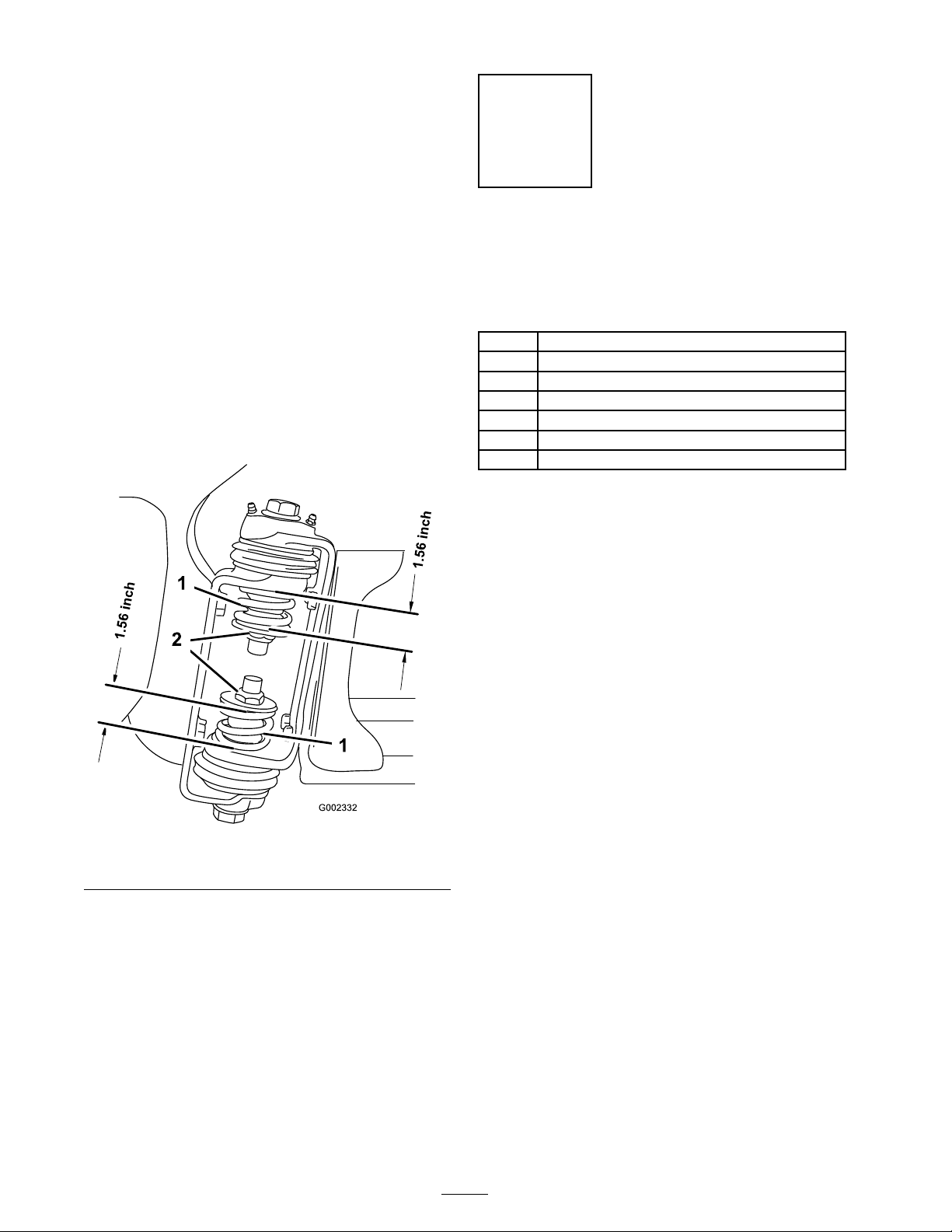
Springs . . . . . . . . . . . . . . . . . . . . . . . . . . . . . . 15
4 Completing the Setup: Lear ning
more about y our
product. . . . . . . . . . . . . . . . . . . . . . . . . . . . . 16
Product Ov er view . . . . . . . . . . . . . . . . . . . . . . . . . . . . . . . . . . . . . . . . . . . . . 17
Controls . . . . . . . . . . . . . . . . . . . . . . . . . . . . . . . . . . . . . . . . . . . 18
Specifications . . . . . . . . . . . . . . . . . . . . . . . . . . . . . . . . . . . 24
Operation . . . . . . . . . . . . . . . . . . . . . . . . . . . . . . . . . . . . . . . . . . . . . . . . . . . . . . . . . . 25
T hink Safety First . . . . . . . . . . . . . . . . . . . . . . . . . . . . . . 25
Before Dri ving the Spra yer for the
First Time . . . . . . . . . . . . . . . . . . . . . . . . . . 25
Pre-Star ting Chec ks . . . . . . . . . . . . . . . . . . . . . . . . . . . 26
Dri ving the Spra yer . . . . . . . . . . . . . . . . . . . . . . . . . . . . 27
New Spra yer Break-In . . . . . . . . . . . . . . . . . . . . . . . 27
Operating the Spra yer . . . . . . . . . . . . . . . . . . . . . . . . 28
Filling the F resh W ater T ank . . . . . . . . . . . . . . . 28
Filling the Spra y T ank . . . . . . . . . . . . . . . . . . . . . . . . 28
Operating the Booms . . . . . . . . . . . . . . . . . . . . . . . . 29
Spra ying . . . . . . . . . . . . . . . . . . . . . . . . . . . . . . . . . . . . . . . . . . . . 30
Spra ying Tips . . . . . . . . . . . . . . . . . . . . . . . . . . . . . . . . . . . . . 30
Cleaning the Spra yer . . . . . . . . . . . . . . . . . . . . . . . . . . 30
Calibrating the Spra y Pro
Monitor . . . . . . . . . . . . . . . . . . . . . . . . . . . . . 33
Calibrating the Boom Bypass
V alv es . . . . . . . . . . . . . . . . . . . . . . . . . . . . . . . . 35
Pump . . . . . . . . . . . . . . . . . . . . . . . . . . . . . . . . . . . . . . . . . . . . . . . . 36
T ranspor ting the Spra yer . . . . . . . . . . . . . . . . . . . . 36
T o wing the Spra yer . . . . . . . . . . . . . . . . . . . . . . . . . . . . 36
Maintenance . . . . . . . . . . . . . . . . . . . . . . . . . . . . . . . . . . . . . . . . . . . . . . . . . . . . . . 38
R ecommended Maintenance
Sc hedule(s) . . . . . . . . . . . . . . . . . . . . . . . . . . . . . . . 38
Daily Maintenance Chec klist . . . . . . . . . . . . . . 40
Notation for Areas of
Concer n . . . . . . . . . . . . . . . . . . . . . . . . . . . . 40
Premaintenance Procedures . . . . . . . . . . . . . . . . . . . . . . . 41
J ac king the Spra yer . . . . . . . . . . . . . . . . . . . . . . . . . . . . . 41
Lubrication . . . . . . . . . . . . . . . . . . . . . . . . . . . . . . . . . . . . . . . . . . . . . . . . 42
Greasing the Spra yer . . . . . . . . . . . . . . . . . . . . . . . . . . 42
Greasing the Boom Hing es . . . . . . . . . . . . . . . . 43
Greasing the Actuator R od
Bearings . . . . . . . . . . . . . . . . . . . . . . . . . . . . 44
Engine Maintenance . . . . . . . . . . . . . . . . . . . . . . . . . . . . . . . . . . 45
Chec king the Air Intak e
Screen . . . . . . . . . . . . . . . . . . . . . . . . . . . . . . . 45
Ser vicing the Air Cleaner . . . . . . . . . . . . . . . . . . . 45
Ser vicing the Engine Oil . . . . . . . . . . . . . . . . . . . . 46
Changing the Spark Plugs . . . . . . . . . . . . . . . . . . . 47
Fuel System Maintenance . . . . . . . . . . . . . . . . . . . . . . . . . . 48
R e placing the Fuel Filter . . . . . . . . . . . . . . . . . . . . 48
Electrical System Maintenance . . . . . . . . . . . . . . . . . . . 49
R e placing the Fuses . . . . . . . . . . . . . . . . . . . . . . . . . . . 49
Ser vicing the Batter y . . . . . . . . . . . . . . . . . . . . . . . . . . 49
Dri v e System Maintenance . . . . . . . . . . . . . . . . . . . . . . . . . 51
Maintaining the Primar y Dri v e
Clutc h . . . . . . . . . . . . . . . . . . . . . . . . . . . . . . . 51
Inspecting the W heels/Tires . . . . . . . . . . . . . . 52
Adjusting the F ront W heel
T oe-In . . . . . . . . . . . . . . . . . . . . . . . . . . . . . . . 52
Brak e Maintenance . . . . . . . . . . . . . . . . . . . . . . . . . . . . . . . . . . . . 53
Chec king the Brak e Fluid . . . . . . . . . . . . . . . . . . . 53
Inspecting the Brak es . . . . . . . . . . . . . . . . . . . . . . . . . 53
Adjusting the P arking Brak e . . . . . . . . . . . . . . . 53
Belt Maintenance . . . . . . . . . . . . . . . . . . . . . . . . . . . . . . . . . . . . . . . 54
Ser vicing the Dri v e Belt . . . . . . . . . . . . . . . . . . . . . 54
Adjusting the Steering Pump
Belt . . . . . . . . . . . . . . . . . . . . . . . . . . . . . . . . . . . 54
Hy draulic System Maintenance . . . . . . . . . . . . . . . . . . 55
Chec king the T ransaxle/Hy draulic
Fluid . . . . . . . . . . . . . . . . . . . . . . . . . . . . . . . . . 55
Changing T ransaxle/Hy draulic
Fluid . . . . . . . . . . . . . . . . . . . . . . . . . . . . . . . . . 55
R e placing the Hy draulic Filter . . . . . . . . . . . . 56
Spra y System Maintenance . . . . . . . . . . . . . . . . . . . . . . . . . 57
Inspecting the Hoses . . . . . . . . . . . . . . . . . . . . . . . . . 57
Pump Maintenance . . . . . . . . . . . . . . . . . . . . . . . . . . . . 57
Adjusting the Boom Actuator . . . . . . . . . . . . 57
Emerg ency Man ual Operation
of the Boom
Actuators . . . . . . . . . . . . . . . . . . . . . . . . . . 58
Inspecting the Nylon Pi v ot
Bushings . . . . . . . . . . . . . . . . . . . . . . . . . . . 58
Cleaning . . . . . . . . . . . . . . . . . . . . . . . . . . . . . . . . . . . . . . . . . . . . . . . . . . . . 59
Cleaning the Flo wmeter . . . . . . . . . . . . . . . . . . . . . 59
Cleaning the Suction Strainer . . . . . . . . . . . . . 59
Storag e . . . . . . . . . . . . . . . . . . . . . . . . . . . . . . . . . . . . . . . . . . . . . . . . . . . . . . . . . . . . . . 61
T roubleshooting . . . . . . . . . . . . . . . . . . . . . . . . . . . . . . . . . . . . . . . . . . . . . . . . 63
Sc hematics . . . . . . . . . . . . . . . . . . . . . . . . . . . . . . . . . . . . . . . . . . . . . . . . . . . . . . . . 69
3
Page 4

Safety
Improper use or maintenance b y the operator or
o wner can result in injur y . T o reduce the potential
for injur y , comply with these safety instr uctions
and alw a ys pa y attention to the safety aler t
symbol, whic h means CA UTION , W ARNING , or
D ANGER—personal safety instr uction. F ailure to
comply with the instr uction ma y result in personal
injur y or death.
Super visors , operators , and ser vice persons should
be familiar with the follo wing standards and
publications: (T he material ma y be obtained from
the address sho wn).
• Flammable and Combustible Liquids Code:
ANSI/NFP A 30
• National Fire Protection Association:
ANSI/NFP A #505; P o w ered Industrial T r uc ks
National Fire Prev ention Association
Bar r ymarc h P ark
Quincy , Massac husetts 02269
U .S .A.
• SAE 2258 Light Utility V ehicles
Society of A utomoti v e Engineers
SAE W orld Headquar ters
400 Commonw ealth Dri v e
W ar rendale , P A 15096-0001
• ANSI/UL 558; Inter nal Combustion
Engine P o w ered Industrial T r uc ks
American National Standards Institute , Inc .
1430 Broadw a y New Y ork,
New Y ork 10018 U .S .A.
or
Underwriters Laboratories
333 Pfingsten R oad
Nor thbrook, Illinois 60062
U .S .A.
Safe Operating Practices
Supervisor’s Responsibilities
• Mak e sure that operators are thoroughly
trained and familiar with the Operator’ s Manual ,
Engine Man ual, and all labels on the spra yer .
• Establish y our o wn special procedures and
w ork r ules for un usual operating conditions
(e .g . slopes too stee p for spra yer operation).
Chemical Safety
Chemicals ar e hazardous and can injur e
y ou, bystander s, animals, plants, soils, or
other pr oper ty .
• Car efull y r ead and f ollo w the chemical
man uf actur er’ s instr uctions f or the safe
pr eparation, use, and disposal of the
chemical.
• K eep chemicals of f of y our or bystander’ s
skin. If contact should occur , w ash it
of f immediatel y with clean w ater and
detergent.
• W ear go g g les and other pr otecti v e
equipment as instr ucted by the chemical
man uf actur er .
• Obtain proper training before using or
handling c hemicals .
• Use the cor rect c hemical for the job .
• F ollo w the c hemical man ufacturer’ s
instr uctions for the safe application of the
c hemical.
• Handle c hemicals in a w ell v entilated area.
• W ear g og gles and other protecti v e equipment
as instr ucted b y the c hemical man ufacturer .
Ensure that as little skin as possible is exposed
while using c hemicals .
T he spray er is an of f-highw ay v ehicle
onl y and is not designed, equipped, or
man uf actur ed f or use on public str eets,
r oads, or highw ays.
• Ha v e clean w ater a v ailable especially when
filling the spra y tank.
• Do not eat, drink, or smok e while w orking
with c hemicals .
• Alw a ys w ash y our hands and other exposed
areas as soon as possible after finishing the
w ork.
4
Page 5
• Properly dispose of un used c hemicals and
c hemical containers as instr ucted b y the
c hemical man ufacturer and y our local codes .
• Chemicals and fumes in the tanks are
dang erous; nev er enter the tank or place y our
head o v er or in the opening .
Before Operating
• Operate the mac hine only after reading and
understanding the contents of this man ual.
• Nev er allo w c hildren to operate the spra yer .
Any one who operates the spra yer should ha v e
a motor v ehicle license .
• Nev er allo w other adults to operate the spra yer
without first reading and understanding the
Operator’ s Manual . Only trained and authorized
persons should operate this spra yer . Mak e sure
that all operators are ph ysically and mentally
capable of operating the spra yer .
• T his spra yer is designed to car r y onl y y ou , the
operator . Nev er car r y any passeng ers on the
spra yer .
• Nev er operate the spra yer when under
the influence of dr ugs or alcohol. Ev en
prescription dr ugs and cold medicines can
cause dro wsiness .
• Be extremely careful when operating around
people . Alw a ys be a w are of where b ystanders
might be and k ee p them a w a y from the w ork
area.
• Before operating the spra yer , alw a ys c hec k the
designated areas of the spra yer that are stated
in the Pre-Star ting Chec ks in the Operation
section. If the mac hine does not function
cor rectly or is damag ed in any w a y , do not use
the spra yer . Mak e sure that the problem is
cor rected before the spra yer or attac hment is
operated.
• Ensure that all fluid line connectors are tight
and all hoses are in g ood condition before
applying pressure to the system.
• Since g asoline is highly flammable , handle it
carefully .
– Use an appro v ed g asoline container .
– Do not remo v e the cap from the fuel tank
when the engine is hot or r unning .
– Do not smok e while handling g asoline .
– Fill the fuel tank outdoors , and fill it to
about 1 inc h (25 mm) belo w the top of the
tank (the bottom of the filler nec k). Do
not o v erfill it.
• Do not dri v e the spra yer when y ou are tired.
Be sure to tak e occasional breaks . It is v er y
impor tant that y ou sta y aler t at all times .
• Become familiar with the controls and kno w
ho w to stop the engine quic kly .
• K ee p all shields , safety devices , and decals in
place . If a shield, safety device , or decal is
malfunctioning, illegible , or damag ed, re pair or
re place it before operating the mac hine .
• Alw a ys w ear substantial shoes . Do not operate
the mac hine while w earing sandals , tennis
shoes , or sneak ers . Do not w ear loose fitting
clothing or jew elr y whic h could g et caught in
mo ving par ts and cause personal injur y .
• W earing safety glasses , safety shoes , long pants ,
and a helmet is advisable and required b y some
local safety and insurance regulations .
• A v oid dri ving when it is dark, especially in
unfamiliar areas . If y ou m ust dri v e when it
is dark, be sure to dri v e cautiously , use the
headlights , and ev en consider adding additional
lights .
– Wipe up any spilled g asoline .
While Operating
Engine exhaust contains carbon mono xide,
which is an odor less, deadl y poison that can
kill y ou.
Do not r un engine indoor s or in an enclosed
ar ea.
• T he operator should remain seated whenev er
the spra yer is in motion. T he operator
should k ee p both hands on the steering wheel
whenev er possible . K ee p y our ar ms and legs
within the spra yer body at all times .
• Alw a ys w atc h out for and a v oid lo w o v erhangs
suc h as tree limbs , door jambs , and o v erhead
w alkw a ys . Mak e sure there is enough room
o v er head to easily clear the spra yer and y our
head.
5
Page 6

• F ailure to operate the spra yer safely ma y result
in an accident, tip o v er of the spra yer , and
serious injur y or death. Dri v e carefully . T o
prev ent tipping or loss of control:
– Use extreme caution, reduce speed, and
maintain a safe distance around sand traps ,
ditc hes , creeks , ramps , unfamiliar areas ,
or any areas that ha v e abr upt c hang es in
g round conditions or elev ation.
– W atc h for holes or other hidden hazards .
– Use extra caution when operating the
spra yer on w et surfaces , in adv erse w eather
conditions , at higher speeds , or with a
full load. Stopping time and distance will
increase with a full load.
– A v oid sudden stops and star ts . Do not
g o from rev erse to forw ard or forw ard to
rev erse without first coming to a complete
stop .
– Slo w do wn before tur ning . Do not attempt
shar p tur ns or abr upt maneuv ers or other
unsafe dri ving actions that ma y cause a loss
of spra yer control.
– Before bac king up , look to the rear and
ensure that no one is behind y ou. Bac k up
slo wly .
– W atc h out for traffic when y ou are near or
crossing roads . Alw a ys yield the right of
w a y to pedestrians and other v ehicles . T his
spra yer is not designed for use on streets or
highw a ys . Alw a ys signal y our tur ns or stop
early enough so that other people kno w
what y ou plan to do . Obey all traffic r ules
and regulations .
– T he electrical and exhaust systems of the
spra yer can produce sparks capable of
igniting explosi v e materials . Nev er operate
the spra yer in or near an area where there is
dust or fumes in the air whic h are explosi v e .
– If y ou are ev er unsure about safe operation,
stop w or k and ask y our super visor .
• Do not touc h the engine or m uffler while the
engine is r unning or soon after it has stopped.
T hese areas ma y be hot enough to cause bur ns .
• If the mac hine ev er vibrates abnor mally , stop
immediately , w ait for all motion to stop , and
inspect the spra yer for damag e . R e pair all
damag e before resuming operation.
• Before g etting off of the seat:
1. Stop the mo v ement of the mac hine .
2. Place the rang e selector in Neutral and set
the parking brak e .
3. T ur n the ignition k ey to Off .
4. R emo v e the ignition k ey .
Note: If the spra yer is stopped on an
incline , bloc k the wheels after g etting off
the spra yer .
Braking
• Slo w do wn before y ou approac h an obstacle .
T his gi v es y ou extra time to stop or tur n a w a y .
Hitting an obstacle can damag e the spra yer and
its contents . More impor tant, it can injure y ou.
• Gross V ehicle W eight (GVW) has a major
impact on y our ability to stop and/or tur n.
Hea vy loads and attac hments mak e a spra yer
harder to stop or tur n. T he hea vier the load,
the long er it tak es to stop .
• T urf and pa v ement are m uc h more slipper y
when they are w et. It can tak e 2 to 4 times
as long to stop on w et surfaces as on dr y
surfaces . If y ou dri v e through standing w ater
dee p enough to g et the brak es w et, they will
not w ork w ell until they are dr y . After dri ving
through w ater , y ou should test the brak es to
mak e sure they w ork properly . If they do not,
dri v e slo wly while putting light pressure on the
brak e pedal. T his will dr y the brak es out.
Operating on Hills and Rough Terrain
Operating the spra yer on a hill ma y cause tipping
or rolling of the spra yer , or the engine ma y stall
and y ou could lose headw a y on the hill. T his could
result in personal injur y .
• Do not accelerate quic kly or slam on the brak es
when bac king do wn a hill, especially with a
load.
• Nev er dri v e across a stee p hill; alw a ys dri v e
straight up or do wn or g o around the hill.
• If the engine stalls or y ou begin to lose headw a y
while climbing a hill, g radually apply the brak es
and slo wly bac k straight do wn the hill.
• T ur ning while tra v eling up or do wn hills can
be dang erous . If y ou ha v e to tur n while on a
hill, do it slo wly and cautiously . Nev er mak e
shar p or fast tur ns .
6
Page 7

• Hea vy loads affect stability . R educe the w eight
of the load and y our speed when operating on
hills .
• A v oid stopping on hills , especially with a load.
Stopping while g oing do wn a hill will tak e
long er than stopping on lev el g round. If the
spra yer m ust be stopped, a v oid sudden speed
c hang es , whic h ma y initiate tipping or rolling
of the spra yer . Do not slam on the brak es
when rolling bac kw ard, as this ma y cause the
spra yer to o v er tur n.
• T he T oro Company strongly recommends
installing the optional R OPS Kit when
operating on hilly ter rain. If y ou install a
R OPS , alw a ys w ear the seat belt when dri ving
the spra yer .
Do not suddenly apply the brak es . Use extra
caution on slopes .
• Be a w are that hea vy loads increase y our
stopping distance and reduce y our ability to
tur n quic kly without tipping o v er .
Maintenance
• Only per mit qualified and authorized personnel
to maintain, re pair , adjust, or inspect the
spra yer .
• Before ser vicing or making adjustments to
the mac hine , stop the engine , set the parking
brak e , and remo v e the k ey from the ignition
to prev ent someone from accidentally star ting
the engine .
• R educe speed and load when operating on
rough ter rain, unev en g round, and near curbs ,
holes , and other sudden c hang es in ter rain.
Loads ma y shift, causing the spra yer to become
unstable .
Sudden changes in ter rain may cause
a br upt steering wheel mo v ement,
possibl y r esulting in hand and ar m
injuries.
• R educe y our speed when operating on rough
ter rain and near curbs .
• Grip the steering wheel loosely around the
perimeter . K ee p y our hands clear of the
steering wheel spok es .
Loading
T he w eight of the carg o can c hang e the spra yer
center of g ra vity and spra yer handling . T o a v oid
loss of control and personal injur y , follo w these
guidelines:
• R educe the w eight of the load when operating
on hills and rough ter rain to a v oid tipping or
o v er tur ning of the spra yer .
• Liquid loads can shift. T his shifting happens
most often while tur ning, g oing up or do wn
hills , suddenly c hanging speeds , or while
dri ving o v er rough surfaces . Shifting loads can
cause the spra yer to tip o v er .
• W hen operating with a hea vy load, reduce y our
speed and allo w for sufficient braking distance .
• T o mak e sure that the entire mac hine is in
g ood condition, k ee p all n uts , bolts , and screws
properly tightened.
• T o reduce the potential for fire , k ee p the engine
area free of ex cessi v e g rease , g rass , lea v es , and
accum ulation of dir t.
• Nev er use an open flame to c hec k the lev el or
leakag e of fuel or batter y electrolyte .
• If the engine m ust be r unning to perfor m a
maintenance adjustment, k ee p y our hands ,
feet, clothing, and any par ts of y our body a w a y
from the engine and any mo ving par ts . K ee p
ev er y one a w a y .
• Do not use open pans of fuel or flammable
cleaning fluids when cleaning par ts .
• Do not adjust the g round speed g o v er nor . T o
ensure safety and accuracy , ha v e an A uthorized
T oro Distributor c hec k the g round speed.
• K ee p y our body and hands a w a y from pin
hole leaks or nozzles that eject high pressure
fluid. Use cardboard or paper to find leaks .
Fluid escaping under pressure can penetrate
skin and cause injur y requiring surg er y within a
few hours b y a qualified surg eon or g ang rene
ma y result.
• If major re pairs are ev er needed or assistance
is required, contact an A uthorized T oro
Distributor .
• T o be sure of optim um perfor mance and safety ,
alw a ys purc hase g en uine T oro re placement
par ts and accessories . R e placement par ts and
accessories made b y other man ufacturers
7
Page 8
could be dang erous . Altering this spra yer in
any manner that ma y affect spra yer operation,
perfor mance , durability , or its use , ma y result
in injur y or death. Suc h use could v oid the
product w ar ranty .
Sound Pressure
T his unit has a maxim um sound pressure lev el
at the operator’ s ear of 82 dB A, based on
measurements of identical mac hines per EN
11094.
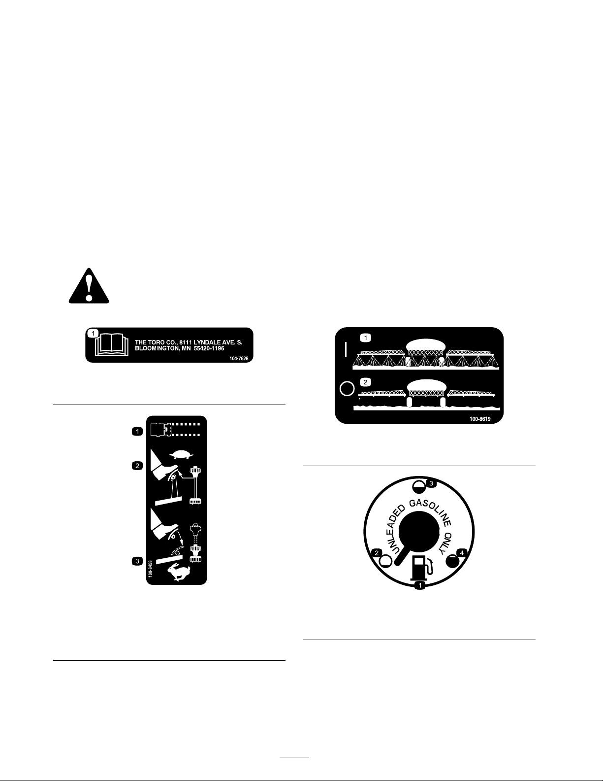
Safety and Instructional Decals
Safety decals and instr uctions are easily visible to the operator and are located near any
area of potential dang er . R e place any decal that is damag ed or lost.
Vibration
T his unit does not ex ceed a hand/ar m vibration
lev el of 2.5 m/s
identical mac hines per EN 1033.
T his unit does not ex ceed a whole body vibration
lev el of 0.5 m/s
identical mac hines per EN 1032.
2
, based on measurements of
2
, based on measurements of
104-7628
1. Read the Operator’s Manual.
100-8458
1. Machine speed
2. To set the machine to a slow speed, reduce pressure on the
accelerator and pull up on the speed limiter.
3. To set the machine to a fast speed, press the accelerator
pedal and push down on the speed limiter.
100-8619
1. Spray on
100-8386
1. Fuel 3. Half-full
2. Empty
2. Spray off
4. Full
8
Page 9
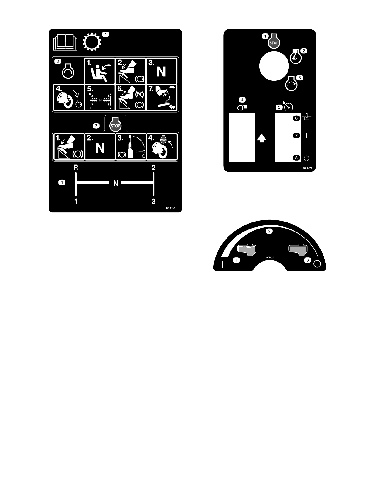
100-8454
1. Read the Operator’s Manual for information on the
transmission.
2. To start the engine, sit on the operator’s seat, press the
brake, set the range selector to Neutral, turn the ignition
key to Engine-start, set the range selector to the desired
gear, release the brake and parking brake, and press the
accelerator pedal to the desired speed.
3. To stop the engine, press the brake, set the range selector
to Neutral, set the brake, and turn the ignition key to
Engine-stop.
4. Range selector gear pattern
100-8470
1. Engine—stop
2. Engine—run
3. Engine—start
4. Headlights 8. Off
107-8621
1. Agitation on
2. Continuous variable setting
5. Neutral engine speed lock
6. Engage
7. On
3. Agitation off
9
Page 10
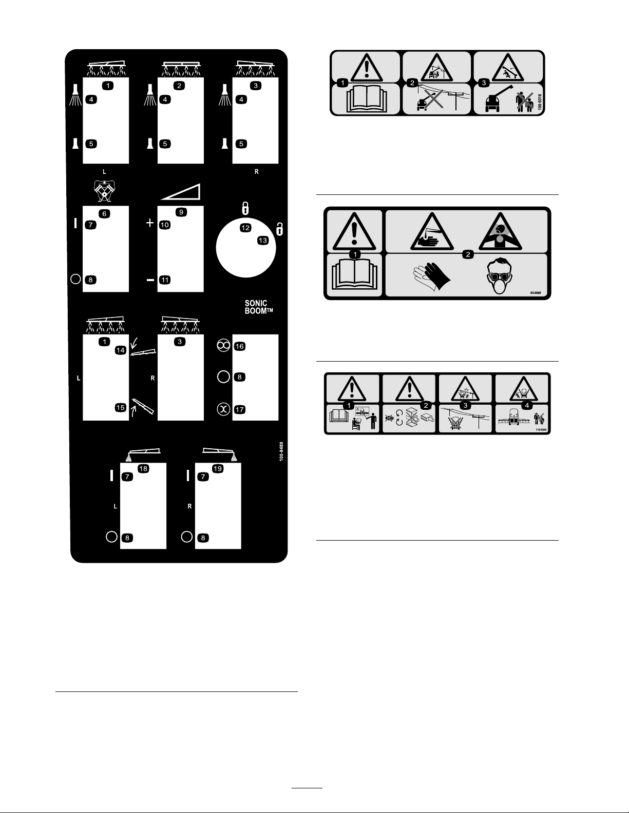
106-5016
1. Warning—read the Operator’s Manual .
2. Electric shock hazard, overhead power lines—stay away from
overhead power lines.
3. Crushing hazard, boom—keep bystanders a safe distance
from the machine.
93-0688
1. Warning—read the Operator’s Manual .
2. Caustic liquid/chemical burn and toxic gas inhalation
hazards—wear hand, skin, eye, and respiratory protection.
100-8489
1. Left boom
2. Center boom 12. Locked
3. Right boom 13. Unlocked
4. Spray on
5. Spray off 15. Raise the boom.
6. Pump
7. On
8. Off 18. Left boom foam marker
9. Continuous variable
setting, spray pressure
10. Increase
11. Decrease
14. Lower the boom.
16. Automatic
17. Manual
19. Right boom foam marker
110-5240
1. Warning—read the Operator’s Manual and receive training
before operating.
2. Warning—stay away from moving parts, do not operate
with covers removed.
3. Electric shock hazard, overhead power lines—stay away from
overhead power lines.
4. Crushing hazard, boom—keep bystanders a safe distance
from the machine.
10
Page 11

110-5143
1. Warning—read the Operator’s Manual .
2. Tipping Hazard—drive slowly over rough terrain and when
turning.
3. Falling and arm/leg injury hazards—do not carry passengers
and keep arms and legs inside of the vehicle at all times.
4. To stop the engine, press the brake, move the range selector
to Neutral, set the parking brake, release the brake pedal,
turn the ignition key to Engine-stop, and remove the key.
107-8640
1. Warning—read the Operator’s Manual ; use fresh, clean water
for rinsing the tank.
106-5051
1. Warning—read the Operator’s Manual ; use fresh, clean water
for rst-aid washing.
108-3307
1. Warning—do not enter the tank.
108-3309
1. Total area 8. Width
2. Boom select
106-1355
3. Speed 10. Speed calibration
4. Units of measure 11. Sub volume
5. Select units 12. Total volume
6. Application rate 13. Flowmeter calibration
7. Sub area
9. Distance
11
Page 12
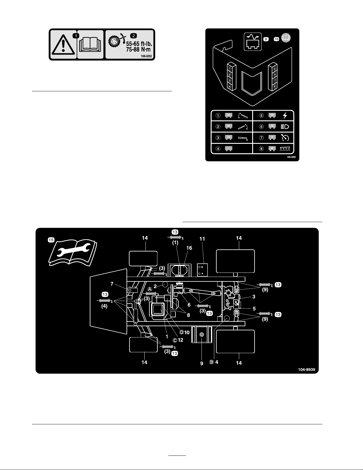
1. Warning—read the
Operator’s Manual .
108-3252
2. Torque lug nuts to 55-65
ft-lb (75-88 N·m).
108-3699
1. 3o amp fuse, left boom
actuator
2. 3o amp fuse, right boom
actuator
3. 15 amp fuse, foam marker 8. 20 amp fuse, spray system
4. Empty
5. 30 amp fuse, power
6. 10 amp fuse, headlights
7. 5 amp fuse, cruise control
9. Fuse panel
10. Read the Operator’s Manual
for more information.
104-8939
1. Engine oil level (dipstick)
2. Engine oil lter 6. Gear box uid level 10. Fuel lter
3. Transaxle/hydraulic uid
level (dipstick)
4. Transaxle hydraulic lter 8. Belts, steering and drive 12. Air cleaner
5. Hydraulic strainer 9. Fuel, unleaded only
7. Brake uid
11. Battery
12
13. Grease
14. Tire pressure
15. Read the instructions before
servicing or performing
maintenance.
16. Pump
Page 13

Setup
Loose Parts
Use the chart below to verify that all parts have been shipped.
Step
90 degree tting
Quick coupler
Hose adapter
1
2
3
4
Fill receptacle bracket
Flange-head bolt, 5/16 x 3/4 inch
Anti-siphon hose
Spray Pro Monitor
Spray Pro Decal
Bracket
Flange-head bolt, 3/4 inch
Flange nut, 1/4 inch
Knob
Washer
Carriage bolt
No parts required
Ignition key
Operator’s Manual
Engine Operator’s Manual
Parts Catalog
Operator Training Material
Registration Card
Pre-delivery Inspection Sheet
Description
Qty.
1
1
1
1
1
1
1
1
1
2
2
2
2
2
–
1
1
1
1
1
1
1
Install the anti-siphon ll receptacle.
Install the Spray-Pro monitor.
Check the boom hinge springs.
Read the manuals and view the
training material before operating
the machine.
Use
Note: Deter mine the left and right sides of the
mac hine from the nor mal operating position.
13
Page 14
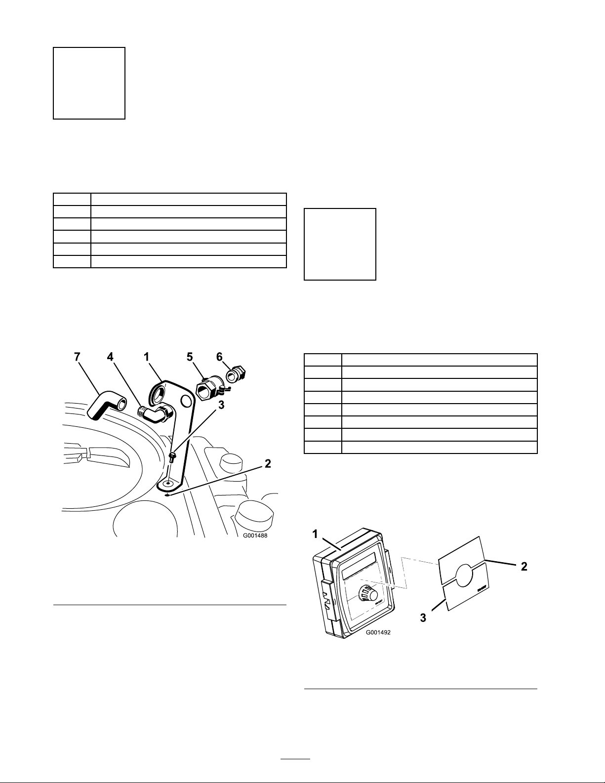
Step
3. Install the hose adapter into the quic k coupler
( Figure 3 ).
4. Loc k the adapter into place b y swinging the
1
lev ers to w ard the adapter and then secure them
with the hair pin cotters ( Figure 3 ).
Installing the Anti-siphon
Fill Receptacle
Parts needed for this step:
1
90 degree tting
1
Quick coupler
1
Hose adapter
1
Fill receptacle bracket
1
Flange-head bolt, 5/16 x 3/4 inch
1
Anti-siphon hose
Procedure
1. Place the fill rece ptacle brac k et o v er the
threaded hole in the tank and secure it with a
flang e-head bolt (5/16 x 3/4 inc h) ( Figure 3 ).
5. Install the anti-siphon hose through the larg e
opening on the brac k et and onto the barbed
end of the 90 deg ree elbo w fitting ( Figure 3 ).
Important: Do not lengthen the hose to
allo w contact with the tank fluids.
Step
2
Installing the Spray Pro
Monitor
Parts needed for this step:
1
Spray Pro Monitor
1
Spray Pro Decal
1
Bracket
2
Flange-head bolt, 3/4 inch
2
Flange nut, 1/4 inch
2
Knob
2
Washer
2
Carriage bolt
Figure 3
1. Fill receptacle bracket 5. Quick coupler
2. Threaded hole in the tank 6. Hose adapter
3. Flange bolt, 5/16 x 3/4 inch 7. Anti-siphon hose
4. 90 degree elbow tting
2. Place the threaded end of the 90 deg ree elbo w
fitting through the brac k et and thread the
quic k coupler onto it, securing it to the brac k et
( Figure 3 ).
Note: Install the fitting with the open end
pointing to w ard the larg e opening in the
brac k et and to w ard the tank opening so the
w ater will arc into the tank when y ou fill it.
Procedure
1. Install the Spra y Pro Decal to the monitor
( Figure 4 ).
Figure 4
1. Spray pro monitor
2. Decal, Upper half
3. Decal, Lower half
Note: Be sure to orient the decal as sho wn
in Figure 20 .
14
Page 15
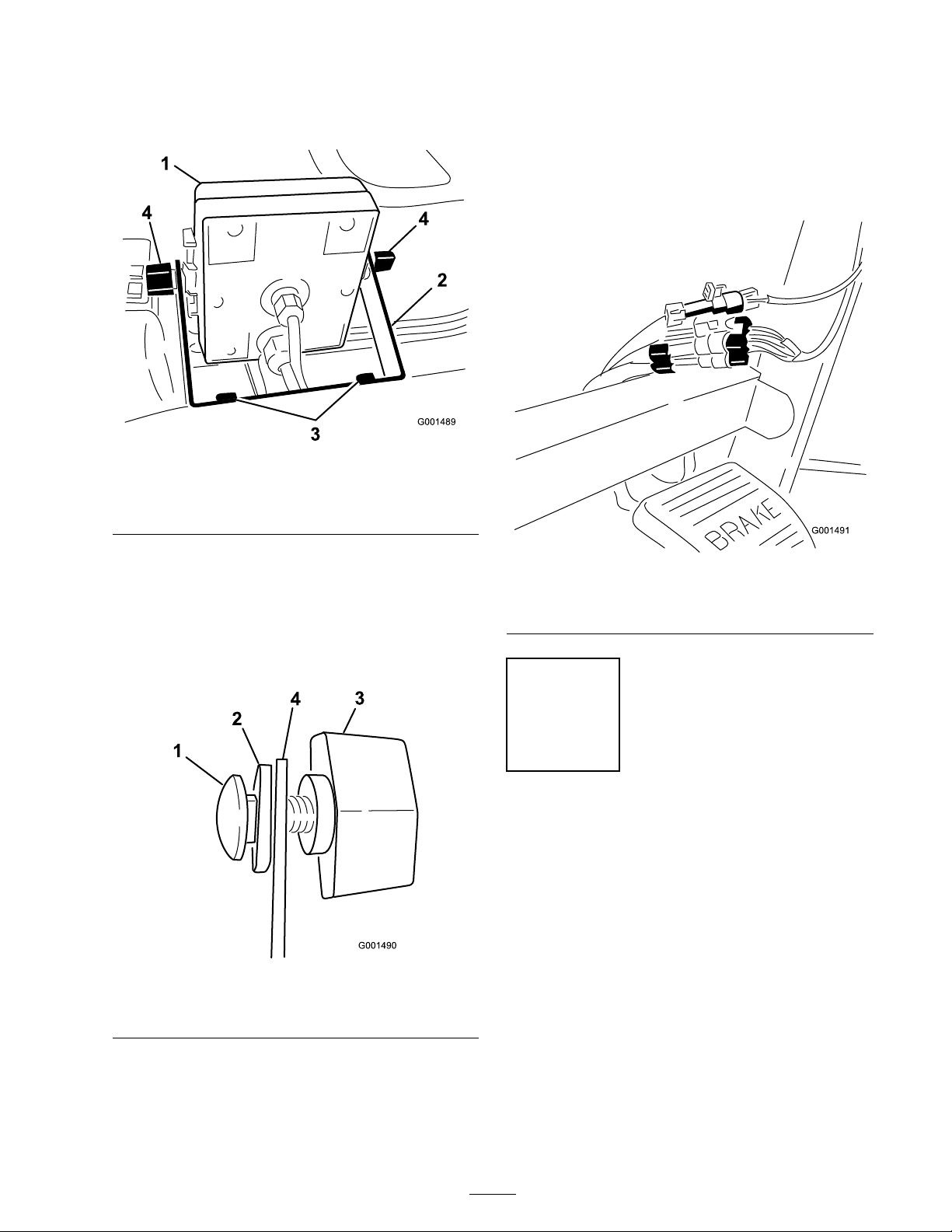
2. Install the monitor brac k et on the dash
( Figure 5 ) using 2 flang e-head bolts
(1/4 x 3/4 inc h) and 2 flang e n uts (1/4 inc h).
Figure 5
1. Spray Pro monitor
2. Bracket 4. Knob
3. Flange-head bolts,
1/4 x 3/4 inch
6. Install the Spra y Pro monitor o v er the car riag e
bolt heads ( Figure 5 ) and tighten the knobs to
secure it.
7. Connect the Spra y Pro wire connectors to
the wire connectors located under the dash
( Figure 7 ).
3. Loosely install the 2 car riag e bolts , r ubber
w ashers , and knobs on the brac k et as illustrated
in Figure Figure 5 and Figure 6 .
Note: Install the car riag e bolts and r ubber
w ashers inside of the brac k et and the knobs
on the outside .
Figure 6
1. Carriage bolt 3. Knob
2. Rubber washer 4. Bracket
4. R emo v e the larg e g rommet from the hole in
the dash and thread the cables on the monitor
through the g rommet and the dash.
5. Install the g rommet into the dash.
Figure 7
1. Connectors from the
sprayer
2. Connectors from the
monitor
Step
3
Checking the Boom Hinge
Springs
No Parts Required
Procedure
Important: Operating the spray system
with the boom hinge springs under the
incor r ect compr ession could dama ge the
boom assembl y . Measur e the springs and use
the jam n ut to compr ess the springs to 1.56
inches if necessar y .
T he spra yer is shipped with the boom extensions
swung forw ard to facilitate pac kaging of the
mac hine . T he springs are not fully tightened at
15
Page 16
the time of man ufacture to allo w the booms to
be in this position for transit. Before operating
the mac hine , the springs m ust be adjusted to the
cor rect compression.
1. If necessar y , remo v e the pac king components
that secure the right and left extension booms
during shipping .
2. Suppor t the booms while they are extended
to the spra y position.
Step
4
Completing the Setup:
Learning more about your
product.
3. At the boom hing e , measure the compression
of the upper and lo w er springs while the booms
are in their extended position ( Figure 8 ).
A. All springs m ust be compressed until they
measure 1.56 inc hes .
B . Use the jam n ut to compress any spring
that measure g reater than 1.56 inc hes .
Parts needed for this step:
1
Ignition key
1
Operator’s Manual
1
Engine Operator’s Manual
1
Parts Catalog
1
Operator Training Material
1
Registration Card
1
Pre-delivery Inspection Sheet
Procedure
1. R ead the man uals .
2. View the Operator training material.
3. Complete the registration card and retur n to
T oro .
4. Store the documentation in a safe place .
Figure 8
1. Boom hinge spring
2. Jam nut
4. R e peat the procedure for eac h spring on both
boom hing es .
5. Mo v e the booms into the transpor t “X”
position. See Operating the Booms in
Operation , pag e 25 for more infor mation.
16
Page 17
Product Overview
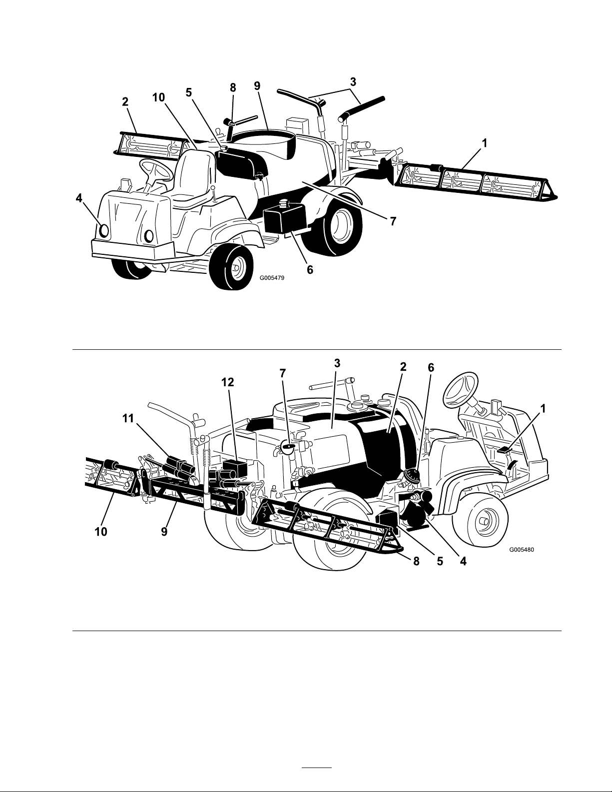
Figure 9
1. Left boom 4. Headlight 7. Chemical tank
2. Right boom 5. Fresh water tank 8. Anti-Siphon Receptacle
3. Boom transport cable 6. Gas tank 9. Tank lid
10. Operator’s position
Figure 10
1. Pedals
2. Rinse tank
3. Chemical tank 6. Pump pressure dampener 9. Center boom 12. Valve cluster
4. Pump
5. Battery
7. Agitation control valve 10. Left boom
8. Right boom 11. Boom control cylinder
17
Page 18
Controls
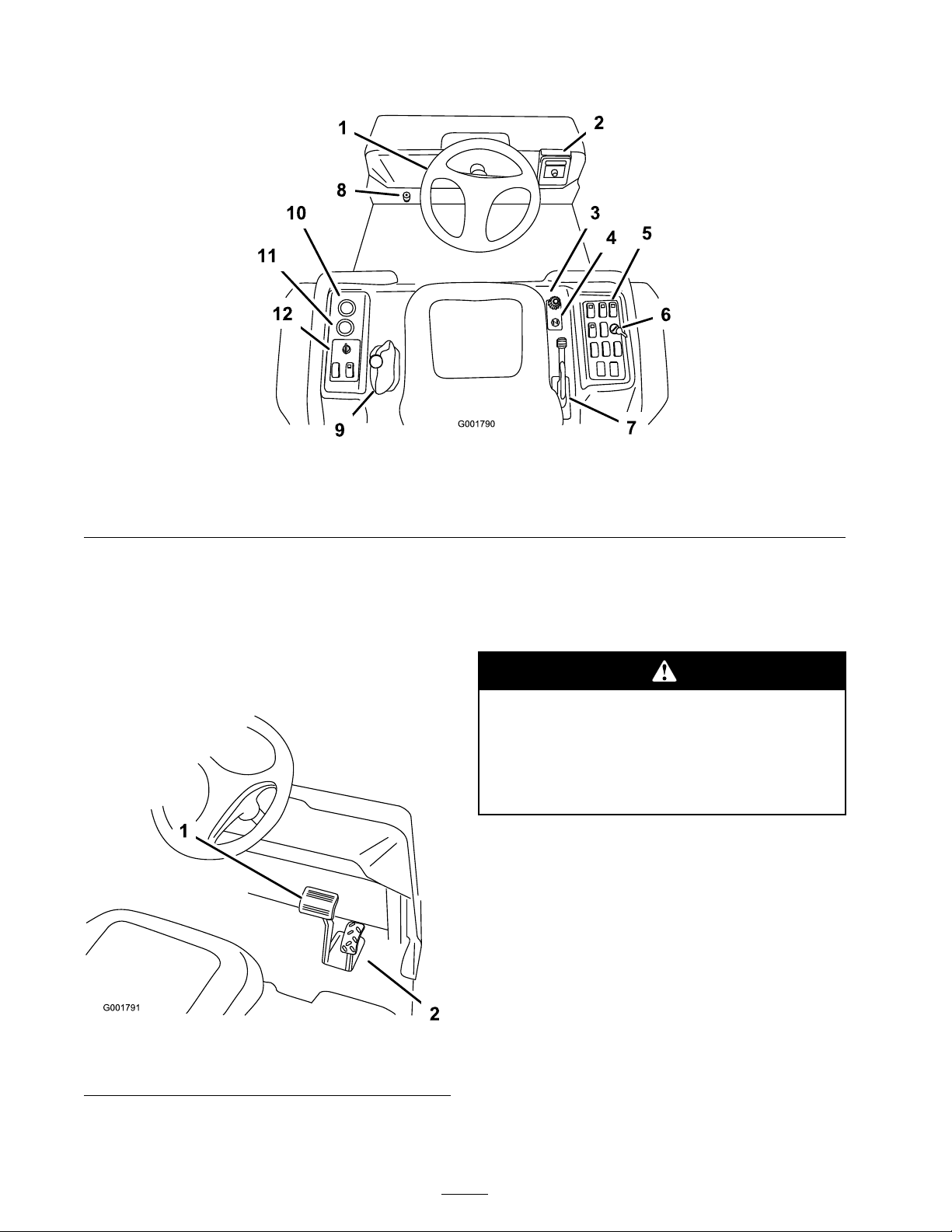
Figure 11
1. Steering wheel 4. Choke 7. Parking brake 10. Voltmeter
2. Spray-Pro monitor
3. Speed limiter 6. Rate lockout switch 9. Range Selector 12. Vehicle controls
5. Sprayer controls 8. Master boom foot switch
11. Hour meter
Accelerator Pedal
T he accelerator pedal ( Figure 12 ) gi v es y ou
the ability to v ar y g round speed of the spra yer .
Pressing the pedal increases g round speed.
R eleasing the pedal will slo w the spra yer and the
engine will idle .
Figure 12
1. Brake pedal 2. Accelerator pedal
Brake Pedal
Use the brak e pedal to stop or slo w the spra yer
( Figure 12 ).
Brak es can become w or n or can be adjusted
incor r ectl y r esulting in per sonal injur y .
If brak e pedal tra v els to within 1 inch
(2.5 cm) of the spray er floor board, the
brak es must be adjusted or r epair ed.
Parking Brake
T he parking brak e is a larg e lev er to the right of
the seat. ( Figure 13 ). Eng ag e the parking brak e
whenev er y ou plan on lea ving the seat to prev ent
accidental mo v ement of the spra yer . T o eng ag e
the parking brak e , pull up and bac k on the lev er .
T o diseng ag e , push it forw ard and do wn. If the
spra yer is park ed on a stee p g rade , apply the
parking brak e and place bloc ks at the do wnhill
side of the wheels .
18
Page 19
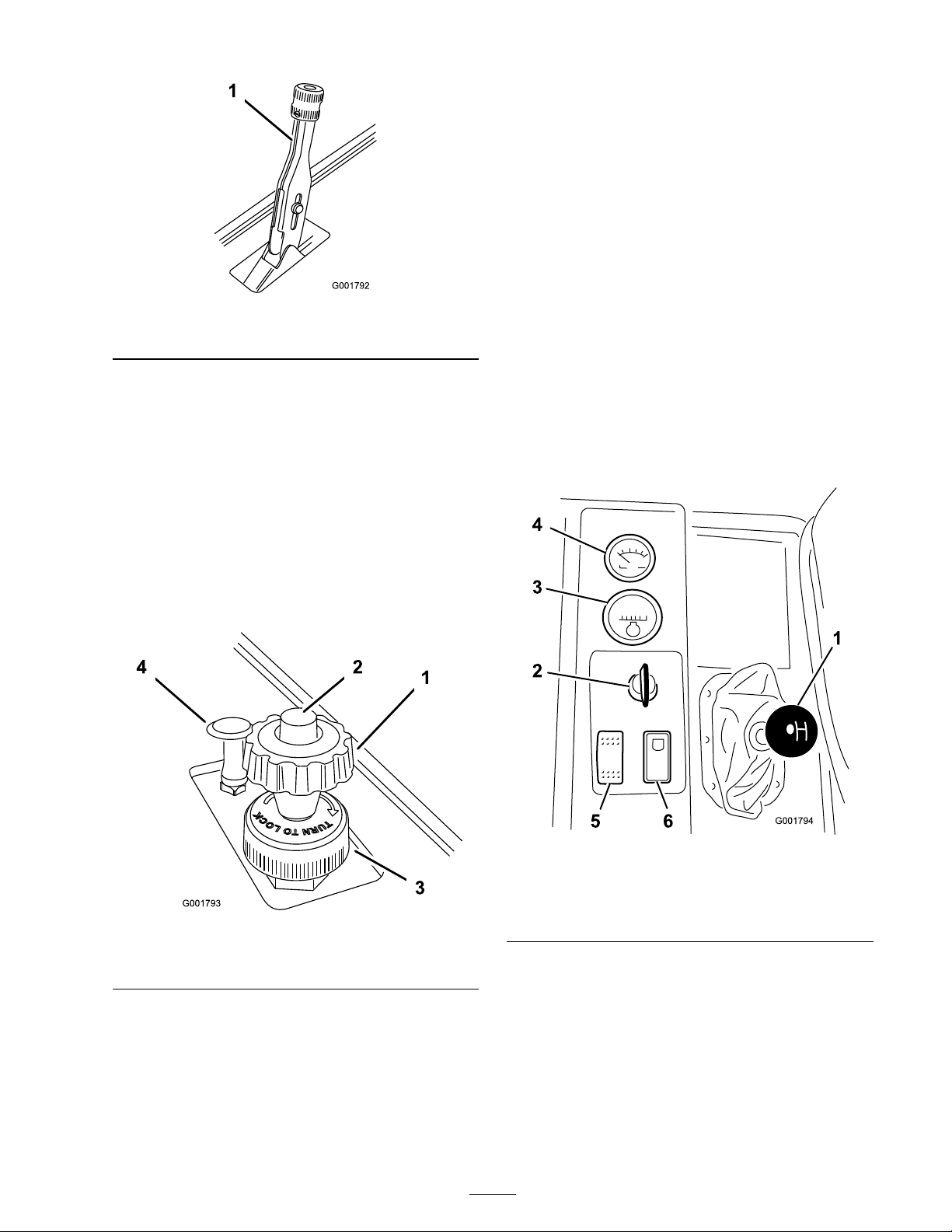
Figure 13
1. Parking brake lever
Speed Limiter
T he speed limiter is a larg e knob located to the
right of the seat ( Figure 14 ). It allo ws y ou to set
the maxim um do wnw ard tra v el of the accelerator
pedal, thereb y limiting the maxim um r pm of the
engine . T his indirectly limits the speed of the
spra yer .
smoothly . As soon as possible , push the control
do wn to the Off position. A w ar m engine requires
little or no c hoking .
Range Selector
T he rang e selector , located to the left of the seat,
has 5 positions: 3 forw ard speeds , Neutral, and
R ev erse ( Figure 15 ). T he engine will star t only
when the rang e selector is in the Neutral position.
Y ou m ust also fully press the brak e with the
spra yer stopped to c hang e rang es .
Important: Do not shift out of or change
ranges while the v ehicle is mo ving . Attempting
to change ranges while the v ehicle is mo ving
can dama ge the transmission. Onl y stopping
the spray er completel y , and full y enga ging the
brak e will safel y disenga ge the locking pin
and allo w the ranges to be changed.
Note: T he v ehicle controls the application rate
based on y our speed and y ou do not need to k ee p
a constant speed to apply at a constant rate .
Figure 14
1. Speed limiter knob 3. Locking ring
2. Speed limiter button 4. Choke control
Choke Control
T he c hok e control is a small knob to the right
of the seat. ( Figure 14 ). T o star t a cold engine ,
pull the c hok e control up . After the engine star ts ,
regulate the c hok e to k ee p the engine r unning
Figure 15
1. Range Selector 4. Voltmeter
2. Ignition switch 5. Headlight switch
3. Hour meter
6. Neutral engine speed lock
switch
Ignition Switch
T he ignition switc h ( Figure 15 ), used to star t
and stop the engine , has 3 positions: Stop , R un,
and Star t. R otate the k ey cloc kwise to the Star t
position to star t the engine and release it to the
R un position when star ted. R otate the k ey to the
Stop position to stop the engine .
19
Page 20
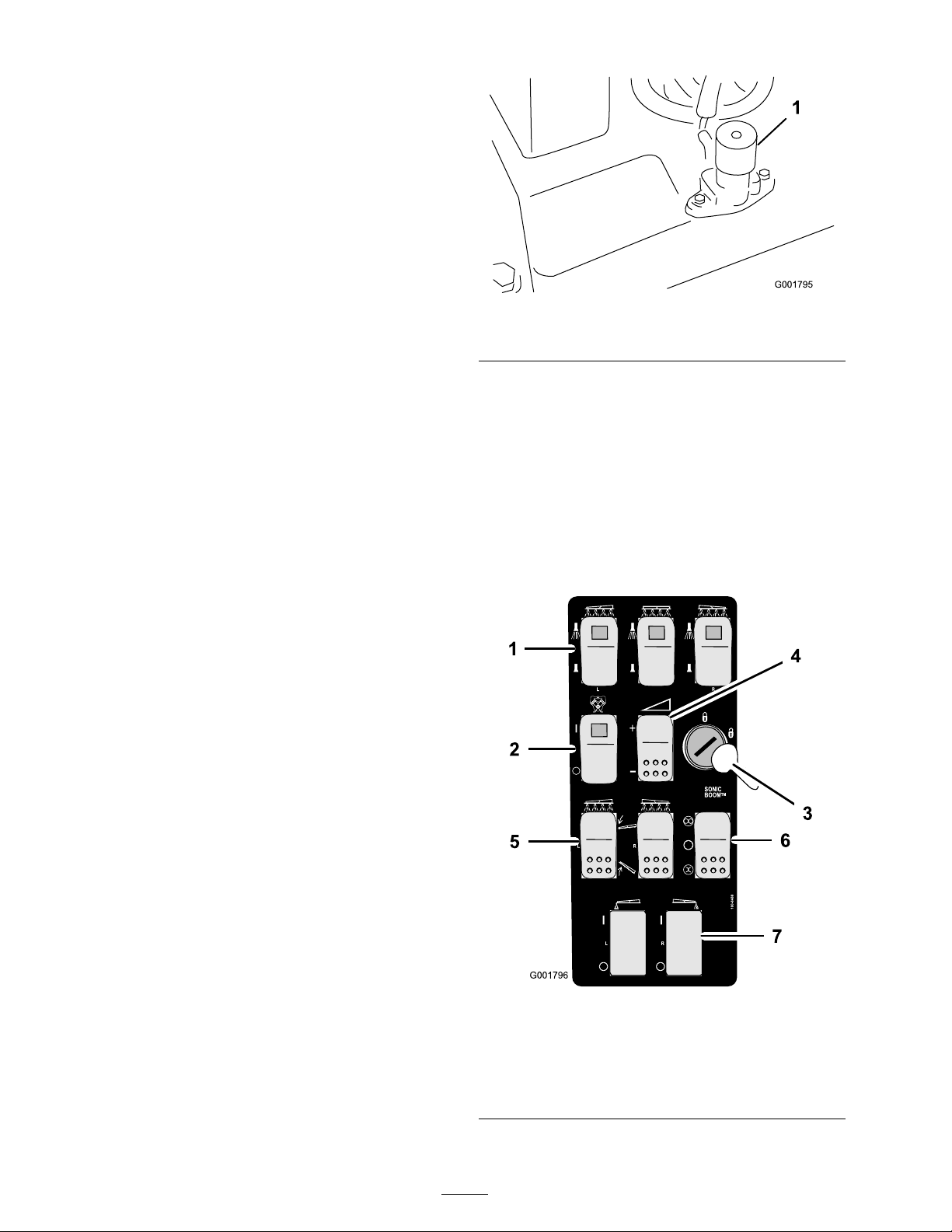
Hour Meter
T he hour meter ( Figure 15 ) indicates the total
n umber of hours the engine has r un. T he hour
meter star ts to function whenev er the k ey is tur ned
to the R un position.
Voltmeter
T he v oltmeter ( Figure 15 ) indicates the lev el of
c harg e in the batter y . W hen the batter y is fully
c harg ed, the v oltmeter will read in the center of
the dial when the k ey is in the R un position with
the engine off . W hen the engine is r unning the
v oltmeter needle should be to the right.
Figure 16
1. Master boom switch
Headlight Switch
T og gle the switc h to operate the headlights
( Figure 15 ). Push it forw ard to tur n the lights on
and rearw ard to tur n them off .
Neutral Engine Speed Lock Switch
W hen the rang e selector is in the Neutral position,
y ou can use the accelerator pedal to speed up the
engine , then push this switc h forw ard to set the
engine at that speed. T his is necessar y to r un the
c hemical agitation while stationar y or operating
attac hments suc h as the hand spra yer ( Figure 15 ).
Important: T he range selector must be in
the neutral position f or the s witch to w or k.
Fuel Gauge
T he fuel g aug e is located on top of the fuel tank,
on the right side of the mac hine and sho ws the
amount of fuel in the tank.
Boom Switches
T he boom switc hes are located at the front
of the control panel to the right of the seat
( Figure 17 ). T og gle eac h switc h forw ard to tur n
the cor responding boom section on and rearw ard
to tur n them off . W hen the switc h is tur ned on,
a light on the switc h illuminates . T hese switc hes
will only affect the spra y system when the master
boom switc h is on.
Master Boom Switch
T he master boom switc h is located on the floor
board of the mac hine cab and to the left of the
operator . It allo ws y ou to star t or stop the spra y
operation. Press the switc h with y our foot to
enable or disable the spra y system ( Figure 16 ).
W hen the master switc h is off , the Spra y Pro
monitor screen reads “Hold."
Figure 17
1. Boom switches, left, right
and center
2. Pump switch 6. Sonic boom switch
3. Rate lockout key 7. Foam marker switch, left
4. Application rate switch
20
5. Boom lift switch, left and
right
and right
Page 21
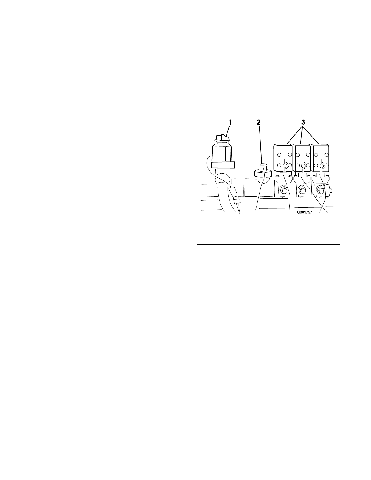
Pump Switch
Rate Control Valve
T he pump switc h is located on the control panel
to the right of the seat ( Figure 17 ). T og gle this
switc h forw ard to r un the pump or rearw ard to
stop the pump .
Important: Onl y enga ge the pump s witch
when the engine is at lo w idle to a v oid
dama ging the pump dri v e.
Application Rate Switch
T he application rate switc h is located on the
control panel to the right of the seat Figure 17 ).
Press and hold the switc h forw ard to increase
the spra y system pressure , or press and hold it
rearw ard to decrease pressure .
Rate Lockout Key Switch
T he rate loc k out k ey switc h is located on the
control panel to the right of the seat ( Figure 17 ).
T ur n the k ey countercloc kwise to the loc k ed
position to disable the application rate switc h,
thereb y k ee ping any one from accidentally c hanging
the application rate . T ur n the k ey cloc kwise to the
unloc k ed position to enable the application rate
switc h.
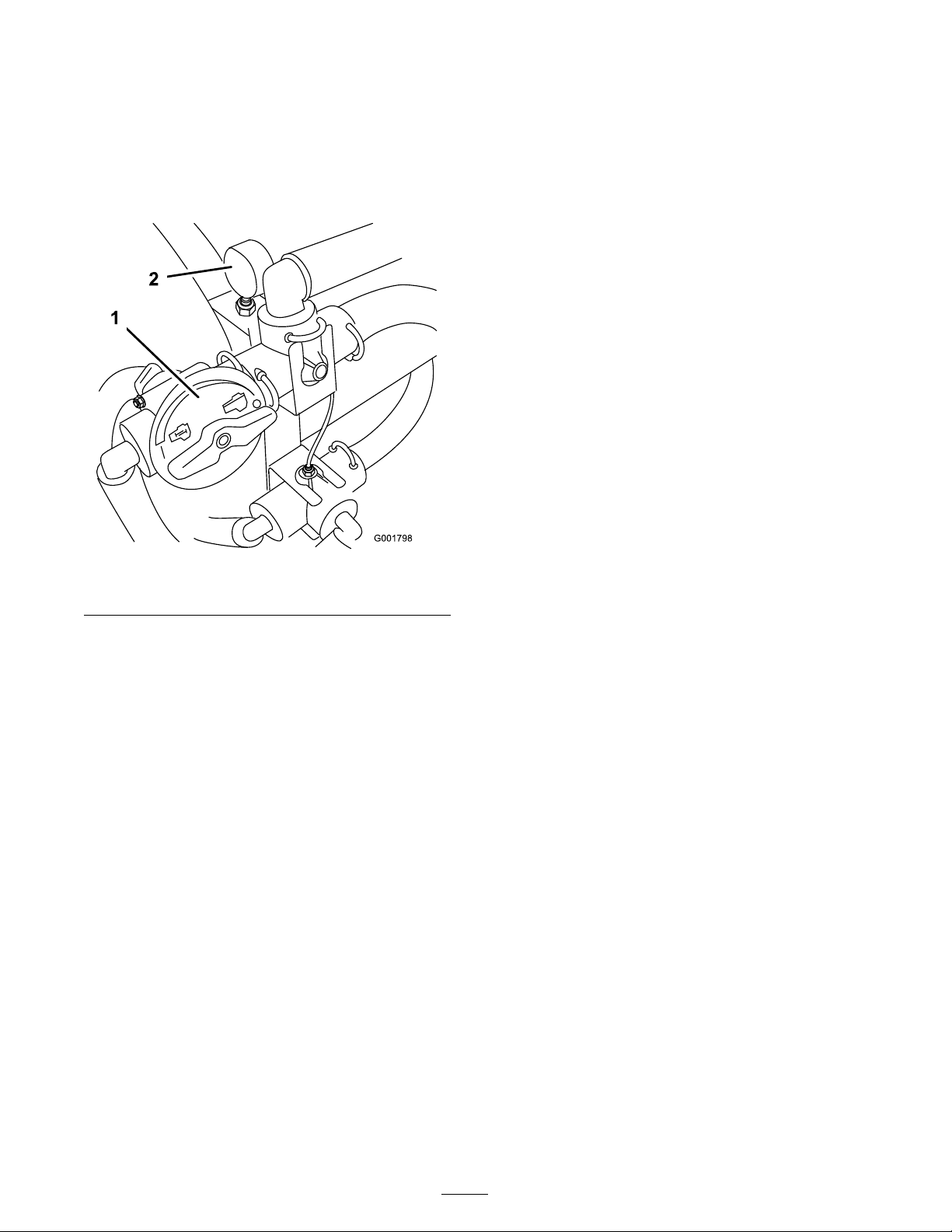
T his v alv e , located behind the tank ( Figure 18 ),
controls the amount of fluid that is routed to the
booms b y directing fluid flo w to the booms or
the b ypass hose to the tank. Y ou can control this
v alv e in tw o w a ys: the application rate switc h or
man ually . T o control it man ually , y ou need to
disconnect the wire connector on the v alv e , then
y ou can rotate the knob on top of the v alv e to
man ually obtain the desired pressure .
Figure 18
1. Rate control valve 3. Boom valves
2. Flowmeter
Important: Do not attempt to mo v e the
range selector while the rate lock out k ey is
enga ged. F orcing the selector while mo ving
will dama ge lock out k ey components.
Boom Lift
T he boom lift switc hes are used to raise the left
and right boom respecti v ely .
Sonic Boom (Optional)
T he Sonic Boom switc h is a roc k er switc h used to
operate the Sonic Boom. T og gle switc h forw ard
for automatic , rearw ard for man ual and center for
Off .
Foam Marker Switch Locations
(Optional)
If y ou install the electric boom lift, sonic boom,
and foam mark er kit, y ou will add switc hes to the
control panel for controlling their operation. T he
spra yer comes with plastic plugs in these locations .
Flowmeter
T he flo wmeter measures the flo w rate of the fluid
for use b y the Spra y Pro™ system ( Figure 18 ).
Boom Valves
T hese v alv es tur n the three booms on or off
( Figure 18 ). If y ou do not ha v e a boom installed
or do not w ant a boom to be able to be tur ned
on, y ou can man ually operate eac h v alv e b y
disconnecting the wire connector in the v alv e , then
rotate the knob on the v alv e cloc kwise to tur n the
v alv e off or countercloc kwise to tur n it on.
Boom Bypass Valves
T he boom b ypass v alv es redirect the fluid flo w for
a boom to the tank when y ou tur n off the boom
section. Y ou can adjust these v alv es to ensure that
the boom pressure remains constant no matter
ho w many booms are on. R efer to Calibrating the
Boom Bypass V alv es , in the Operation section.
21
Page 22
Agitation Control Valve
Pressure Gauge
T his v alv e is located on the right side of the tank
( Figure 19 ). T ur n the knob on the v alv e to the
9 o’cloc k position to tur n on the tank agitation
and to the 3 o’cloc k position to tur n off the tank
agitation.
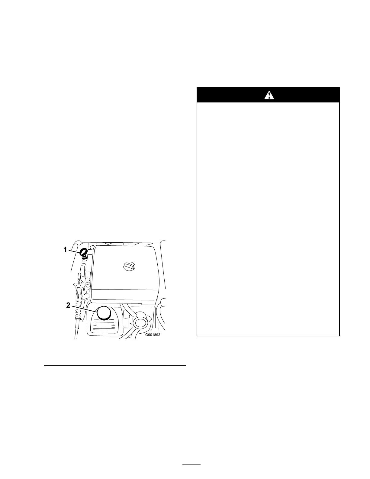
Figure 19
1. Agitation control valve
2. Pressure gauge
T he pressure g aug e is located to the right of the
tank ( Figure 19 ). T his g aug e sho ws the pressure
of the fluid in the system in psi and kP a. Use the
g aug e to adjust the b y-pass v alv es whenev er y ou
c hang e nozzles .
Anti-siphon Fill Receptacle
T o the front of the tank co v er is a hose rece ptacle
with a threaded fitting, a 90 deg ree barbed fitting,
and a shor t hose whic h y ou can direct to w ard
the tank opening . T his rece ptacle allo ws y ou to
connect a w ater hose to it and fill the tank with
w ater without contaminating the hose with the
c hemicals in the tank.
Important: Do not lengthen the hose to
allo w contact with the tank fluids.
Note: F or agitation to w ork, the pump m ust
be on and the engine m ust be r unning abo v e an
idle . If y ou stop the spra yer and need agitation on,
place the rang e selector in the Neutral position, set
the parking brak e , press the accelerator pedal to
the floor , tur n the pump On and tur n the neutral
engine speed loc k On.
22
Page 23

Spray Pro™ Monitor
T he Spra y Pro monitor displa ys and monitors
v arious system perfor mance data suc h as v ehicle
speed and application rates . It does not control
the application rate .
T he monitor has an LCD screen that displa ys the
data y ou select, a selection dial, and 4 buttons for
calibrating the monitor ( Figure 20 ).
Figure 20
1. LCD screen
2. Selection dial
3. Total area 8. Sub Area 13. Decrease, calibration button 18. Speed calibration
4. Speed 9. Sub volume 14. Increase, calibration button 19. Flowmeter calibration
5. Units of measure 10. Total volume 15. Boom selection
Monitor Display Selection Dial
Use the dial to set the LCD screen displa y to the
follo wing:
• T otal ar ea
Displa ys the total acres (US), hectares (SI), or
sq feet (TURF) that y ou ha v e co v ered since
y ou last pressed the R eset calibration button
for this setting .
• Speed
Displa ys the g round speed in miles per hour (if
the Units of Measure is set to US or TURF) or
kilometers per hour (if the Units of Measure
is set to SI).
• Units of Measur e
Displa ys the cur rent measurement unit
selection as follo ws:
6. Application rate 11. Reset, calibration button 16. Select units
7. Distance
12. Calibrate, calibration button 17. Width
20. LED
– SI (metric system)
– TURF (as US but the v olumes are in US
g allons per 1000 sq ft instead of US g allons
per acre)
• Application R ate
Displa ys the application rate in US g allons per
acre (US), liters pre hectare (SI), or US g allons
per 1000 sq ft (TURF).
• Sub Ar ea
Displa ys the total acres (US), hectares (SI), or
sq feet (TURF) that y ou ha v e co v ered since
y ou last pressed the R eset calibration button
for this setting, without affecting the T otal
Area displa y . If y ou press the R eset calibration
button, the Sub V olume resets .
• Distance
– US (United States measuring system)
23
Page 24

Displa ys the distance y ou ha v e tra v eled in feet
(US and TURF) or meters (SI) since y ou last
pressed the R eset calibration button for this
setting .
• Sub V olume
Displa ys the total v olume in US g allons (US
and TURF) or liters (SI) that y ou ha v e applied
since y ou last pressed the R eset calibration
button for this setting, without affecting the
T otal V olume displa y . If y ou press the R eset
calibration button, the Sub Area resets .
• T otal V olume
Displa ys the total v olume in US g allons (US
and TURF) or liters (SI) that y ou ha v e applied
since y ou last pressed the R eset calibration
button for this setting .
Calibration Buttons
T he monitor has the follo wing buttons:
• R eset
R esets the T otal V olume , Sub V olume ,
Distance , T otal Area, and Sub Area displa y
settings to 0.
• Calibrate
Used to enter and exit the calibration mode .
• Decr ease
R educes v alues displa yed on the screen during
calibration.
• Incr ease
Increases v alues displa yed on the screen during
calibration.
Calibration Settings
Specications
Note: Specifications and design are subject to
c hang e without notice .
Base weight
Weight with standard
spray system, empty,
without operator
Weight with standard
spray system, full, without
operator
Maximum gross
vehicle weight (GVW)
(on level ground)
Tank capacity (includes
the CE 5% overow)
Overall width with
standard spray system
booms stored in the X
position
Overall length with
standard spray system
Overall height with
standard spray system
Overall height with
standard spray system
to the top of the booms
stored in the X position
Ground clearance
Wheel base
Optional Equipment
T he T oro Company has optional equipment and
accessories that y ou can purc hase se parately and
install on y our spra yer . Contact y our A uthorized
Ser vice Dealer for a complete list of optional
equipment that is cur rently a v ailable for y our
spra yer .
2,061 lb (934 kg)
2,061 lb (934 kg)
3,661 lb (1,660 kg)
4,163 lb (1,888 kg)
175 US gallons (662 L)
69 inches (175 cm)
133 inches (337 cm)
52 inches (132 cm)
91 inches (231 cm)
4.5 inches (11.4 cm)
62 inches (157 cm)
• Boom Width
• Units of Measure
• Speed/Distance
• Flo wmeter
24
Page 25
Operation
Note: Deter mine the left and right sides of the
mac hine from the nor mal operating position.
Check the Tire Pressure
Chec k the tire pressure ev er y 8 hours or daily
to ensure proper lev els . Fill the tires to 18 psi
(124 kP a). Also , c hec k the tires for w ear or damag e .
Think Safety First
Please carefully read all of the safety instr uctions
and decals in the safety section. Kno wing this
infor mation could help y ou or b ystanders a v oid
injur y .
Before Driving the Sprayer
for the First Time
Check the Engine Oil
T he engine is shipped with oil in the crankcase;
ho w ev er , the lev el of oil m ust be c hec k ed before
y ou first star t the engine and after y ou ha v e r un it.
1. P osition the mac hine on a lev el surface .
2. R emo v e the dipstic k and wipe it with a clean
rag ( Figure 21 ). Inser t the dipstic k into the
tube and mak e sure it is seated fully . R emo v e
the dipstic k and c hec k the oil lev el.
Add Fuel
In cer tain conditions, gasoline is extr emel y
flamma ble and highl y explosi v e. A fir e or
explosion fr om gasoline can bur n y ou and
other s and can dama ge pr oper ty .
• Fill the fuel tank outdoor s, in an open
ar ea, when the engine is cold. W ipe up
an y gasoline that spills.
• Nev er fill the fuel tank inside an enclosed
trailer .
• Do not fill the fuel tank completel y full.
Add gasoline to the fuel tank until the
lev el is 1/4 to 1/2 inch (6 to 13 mm)
belo w the bottom of the filler neck. T his
empty space in the tank allo ws gasoline
to expand.
• Nev er smok e when handling gasoline,
and stay a w ay fr om an open flame or
wher e gasoline fumes may be ignited by
a spar k.
Figure 21
1. Dipstick 2. Filler cap
3. If the oil lev el is lo w , remo v e the filler cap
from the v alv e co v er ( Figure 21 ) and pour oil
into the opening until the oil lev el is up to the
Full mark on the dipstic k; refer to Ser vicing
Engine Oil, Engine Maintenance , pag e 45 , for
the proper oil type and viscosity . Add the oil
slo wly and c hec k the lev el often during this
process . Do not o v erfill.
4. Install the dipstic k fir mly in place .
• Stor e gasoline in an appr o v ed container
and k eep it out of the r each of childr en.
Nev er buy mor e than a 30-day suppl y of
gasoline.
• Do not operate without entir e exhaust
system in place and in pr oper w or king
condition.
25
Page 26
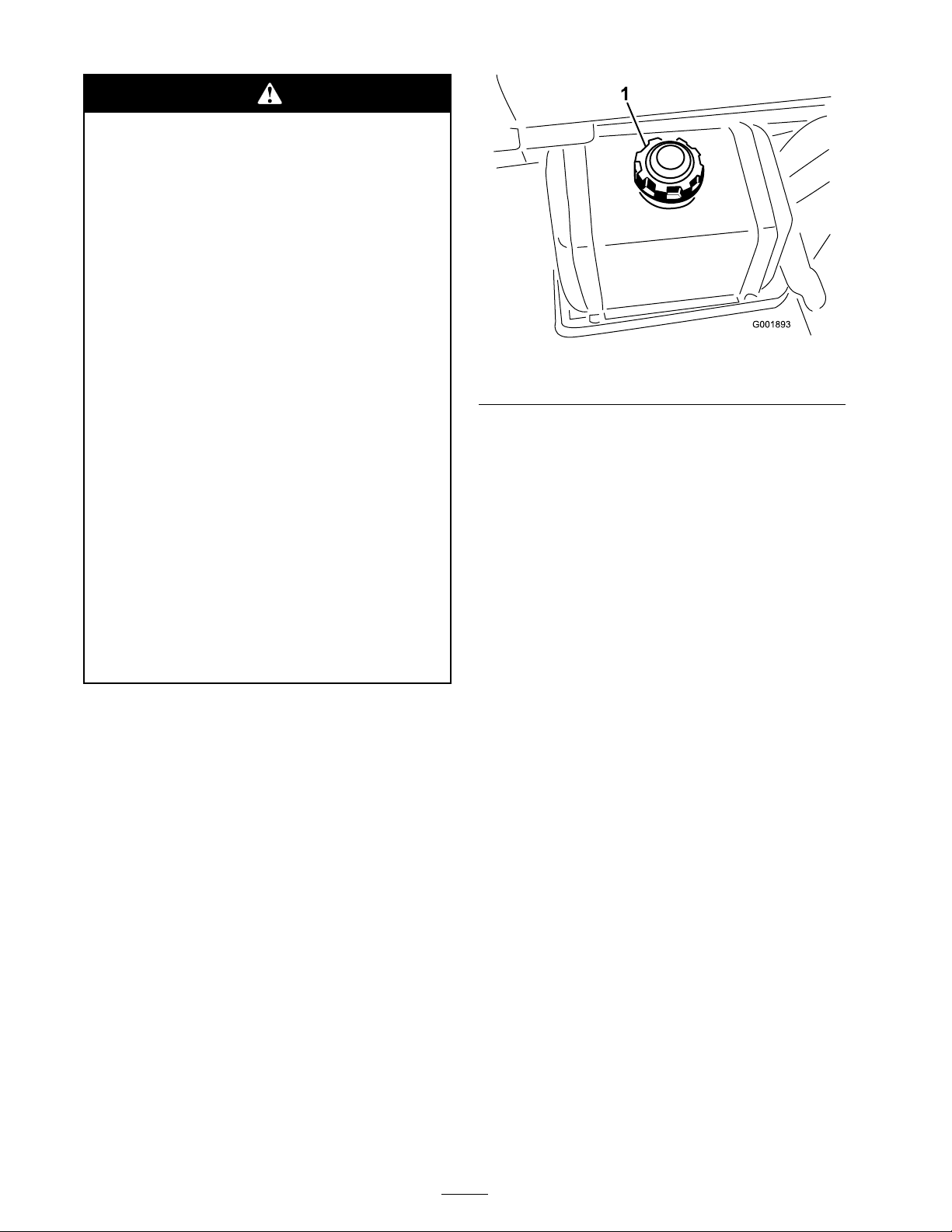
In cer tain conditions during fueling , static
electricity can be r eleased causing a spar k
which can ignite the gasoline v apor s. A fir e
or explosion fr om gasoline can bur n y ou and
other s and can dama ge pr oper ty .
• Al w ays place gasoline container s on the
g r ound a w ay fr om y our v ehicle bef or e
filling .
• Do not fill gasoline container s inside
a v ehicle or on a tr uck or trailer bed
because interior car pets or plastic tr uck
bed liner s may insulate the container and
slo w the loss of an y static charge.
Figure 22
1. Fuel tank cap
• W hen practical, r emo v e gas-po w er ed
equipment fr om the tr uck or trailer and
r efuel the equipment with its wheels on
the g r ound.
• If this is not possible, then r efuel such
equipment on a tr uck or trailer fr om a
por ta ble container , rather than fr om a
gasoline dispenser nozzle.
• If a gasoline dispenser nozzle must be
used, k eep the nozzle in contact with the
rim of the fuel tank or container opening
at all times until fueling is complete.
R ecommended Gasoline
Use fresh, clean, unleaded regular g asoline suitable
for automoti v e use (87 pump octane minim um).
Leaded g asoline ma y be used if unleaded regular is
not a v ailable .
Important: Nev er use gasoline containing
methanol, gasoline containing mor e than
10% ethanol, gasoline additi v es, or white gas
because engine fuel system dama ge could
r esult.
3. R emo v e the fuel tank cap .
4. Fill the tank to about one inc h belo w the top
of the tank, (bottom of the filler nec k). T his
space in the tank allo ws g asoline to expand.
Do not o v erfill.
5. Install the fuel tank cap securely .
6. Wipe up any fuel that ma y ha v e spilled.
Pre-Starting Checks
Chec k the follo wing items eac h time y ou begin
using the spra yer for the da y:
• Chec k the tire pressure .
Note: T hese tires are different than car tires;
they require less pressure to minimize turf
compaction and damag e .
• Chec k all fluid lev els and add the appropriate
amount of specified fluids , if any are found to
be lo w .
• Chec k the brak e pedal operation.
• Chec k to see that the lights are w orking .
Filling the Fuel T ank
T he fuel tank capacity is appro ximately 6 US
g allons (21 L).
Note: T he fuel tank cap contains a g aug e whic h
sho ws the fuel lev el; c hec k it frequently .
1. Shut the engine off and set the parking brak e .
2. Clean the area around the fuel tank cap
( Figure 22 ).
• T ur n the steering wheel to the left and right to
c hec k steering response .
• Chec k for oil leaks , loose par ts , and any other
noticeable malfunctions . Mak e sure the engine
is off and all mo ving par ts ha v e stopped before
c hec king for oil leaks , loose par ts , and other
malfunctions .
If any of the abo v e items are not cor rect, notify
y our mec hanic or c hec k with y our super visor
26
Page 27

before taking the spra yer out for the da y . Y our
super visor ma y w ant y ou to c hec k other items on
a daily basis , so ask what y our responsibilities are .
Driving the Sprayer
Starting the Engine
1. Sit in the Operator’ s seat, inser t the k ey into the
ignition switc h, and rotate the k ey cloc kwise to
the R un position.
2. Press the brak e and mo v e the rang e selector to
the Neutral position.
3. Ensure that the pump switc h is in the Off
position.
4. If the engine is cold, pull the c hok e knob up .
Figure 23
1. Speed limiter knob 3. Locking ring
2. Speed limiter button 4. Choke control
3. T o fine tune the setting, tur n the knob in or
out as needed.
Important: Do not use the chok e if the
engine is w ar m.
5. T ur n the k ey to the Star t position until the
engine star ts .
Important: Do not hold the k ey in the
Star t position f or mor e than 10 seconds. If
the engine has not star ted after 10 seconds,
w ait 1 min ute bef or e tr ying a gain. Do not
attempt to push or to w the spray er to star t
the engine.
6. Once the engine star ts , push the c hok e knob
do wn slo wly .
Driving
1. Press the brak e pedal.
2. Push the parking brak e lev er forw ard to release
it.
3. Mo v e the rang e selector into the desired rang e .
4. Press the accelerator pedal to dri v e or press
the brak e to stop .
Note: Stopping distance ma y v ar y de pending
on the spra yer load and speed.
Setting the Speed Limiter
1. Press do wn on the accelerator pedal to obtain
the desired speed.
2. Press the button on top of the speed limiter
knob and pull up on it until y ou feel it touc h
the accelerator pedal, then release the button
( Figure 23 ).
4. Once y ou ha v e it set, y ou can loc k it at that
setting b y tur ning the loc king ring at the base
of the speed limiter cloc kwise until it stops
( Figure 23 ). T o release this loc k, tur n the
loc king ring counter cloc kwise until it is loose .
5. T o release the speed limiter , press the button
on the knob and lo w er it as far as possible .
Stopping the Engine
1. Press the brak e to stop the spra yer .
2. Pull the parking brak e lev er up and bac k to
set it.
3. Mo v e the rang e selector out of g ear into the
Neutral position.
4. T ur n the ignition k ey to the Stop position.
5. R emo v e the k ey from the switc h to prev ent
accidental star ting .
New Sprayer Break-In
T o pro vide proper perfor mance and long
spra yer life , follo w these guidelines for the first
100 operating hours:
• Chec k the fluid and engine oil lev els regularly
and be aler t for indications of o v erheating in
any component of the spra yer .
• After star ting a cold engine , let it w ar m up for
about 15 seconds before accelerating .
• A v oid hard braking situations for the first
sev eral hours of new spra yer break-in
operation. New brak e linings ma y not be at
27
Page 28
optim um perfor mance until sev eral hours of
use has caused the brak es to become bur nished
(brok en-in).
is a v ailable in a for m ulation that w ould pro vide
increased life to the spra yer , use this alter nati v e
for m ulation.
• A v oid racing the engine .
• V ar y the spra yer speed during operation. A v oid
fast star ts and quic k stops .
• R efer to the Maintenance section for any
special lo w hour c hec ks .
Operating the Sprayer
T o operate the Multi-Pro Spra yer first fill the spra y
tank, then apply the solution to the w ork area,
and finally clean the tank. It is impor tant that y ou
complete all three of these ste ps in succession to
a v oid damaging the spra yer . F or example , do not
mix and add c hemicals in the spra y tank at night
and then spra y in the mor ning . T his w ould lead to
se paration of the c hemicals and possible damag e
to the spra yer components .
Chemicals ar e hazardous and can cause
per sonal injur y .
As alw a ys , remember to clean y our spra yer
thoroughly after all applications . T his will do the
most to ensure y our spra yer has a long and trouble
free life .
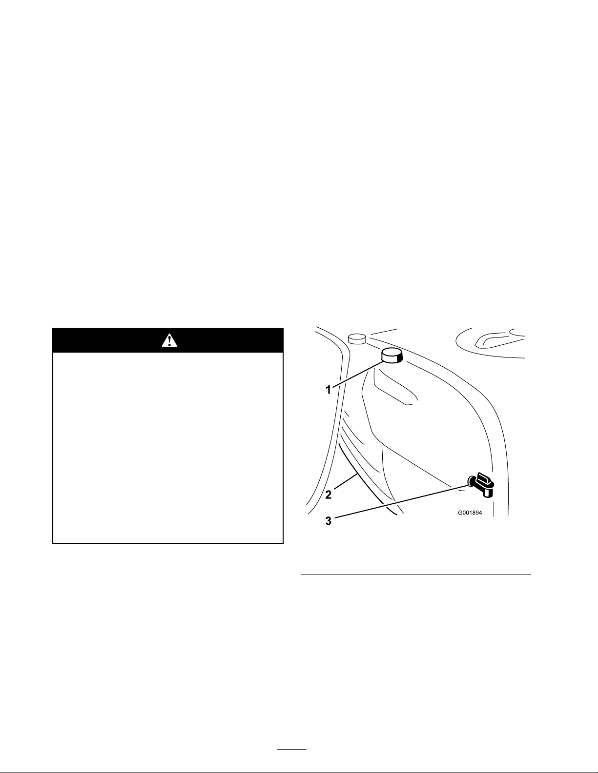
Filling the Fresh Water Tank
Alw a ys fill the fresh w ater tank with clean w ater
before handling or mixing any c hemicals .
T he fresh w ater tank is located at the front, left
side of the tank ( Figure 24 ). It supplies a source
of fresh w ater for y ou to w ash c hemicals off of
y our skin, eyes , or other surfaces in the case of
accidental exposure .
T o open the fresh w ater tank spig ot, tur n the lev er
on the spig ot.
• R ead the dir ections on the chemical
la bels bef or e handling the chemicals
and f ollo w all man uf actur er
r ecommendations and pr ecautions.
• K eep chemicals a w ay fr om y our skin.
Should contact occur , w ash the af fected
ar ea thor oughl y with soap and clean
w ater .
• W ear go g g les and an y other pr otecti v e
equipment r ecommended by the
chemical man uf actur er .
T he Multi-Pro Spra yer has been specifically
designed to ha v e high durability in order to gi v e it
the long spra yer life y ou need. Different materials
ha v e been c hosen for specific reasons at different
locations on y our spra yer to meet this g oal.
Unfor tunately there is no single material whic h is
perfect for all foreseeable applications .
Some c hemicals are more ag g ressi v e than others
and eac h c hemical interacts differently with v arious
materials . Some consistencies (e .g . w ettable
po w ders , c harcoal) are more abrasi v e and lead
to higher than nor mal w ear rates . If a c hemical
Figure 24
1. Fresh water tank
2. Filler cap
3. Spigot
Filling the Spray Tank
Important: Ensur e that the chemicals y ou
will be using ar e compatible f or use with
V iton (see the man uf actur er’ s la bel; it should
indicate if it is not compatible). Using a
chemical that is not compatible with V iton will
deg rade the O-rings in the spray er , causing
leaks.
28
Page 29
Important: V erify that the pr oper
G001897
1
2
application rate has been set prior to filling the
tank with chemicals.
1. Stop the spra yer on a lev el surface , mo v e the
rang e selector to the Neutral position, stop the
engine , and set the parking brak e .
2. Ensure that the tank drain v alv e is closed.
3. Deter mine the amount of w ater needed to mix
the amount of c hemical y ou need as prescribed
b y the c hemical man ufacturer .
4. Open the tank co v er on the spra y tank.
9. T ur n the agitation control v alv e to the 9 o’cloc k
position to star t agitation in the tank.
10. Add the proper amount of c hemical
concentrate to the tank, as directed b y the
c hemical man ufacturer .
Important: If y ou ar e using a w etta ble
po w der , mix the po w der with a small
amount of w ater to f or m a slur r y bef or e
adding it to the tank
11. Add the remaining w ater to the tank.
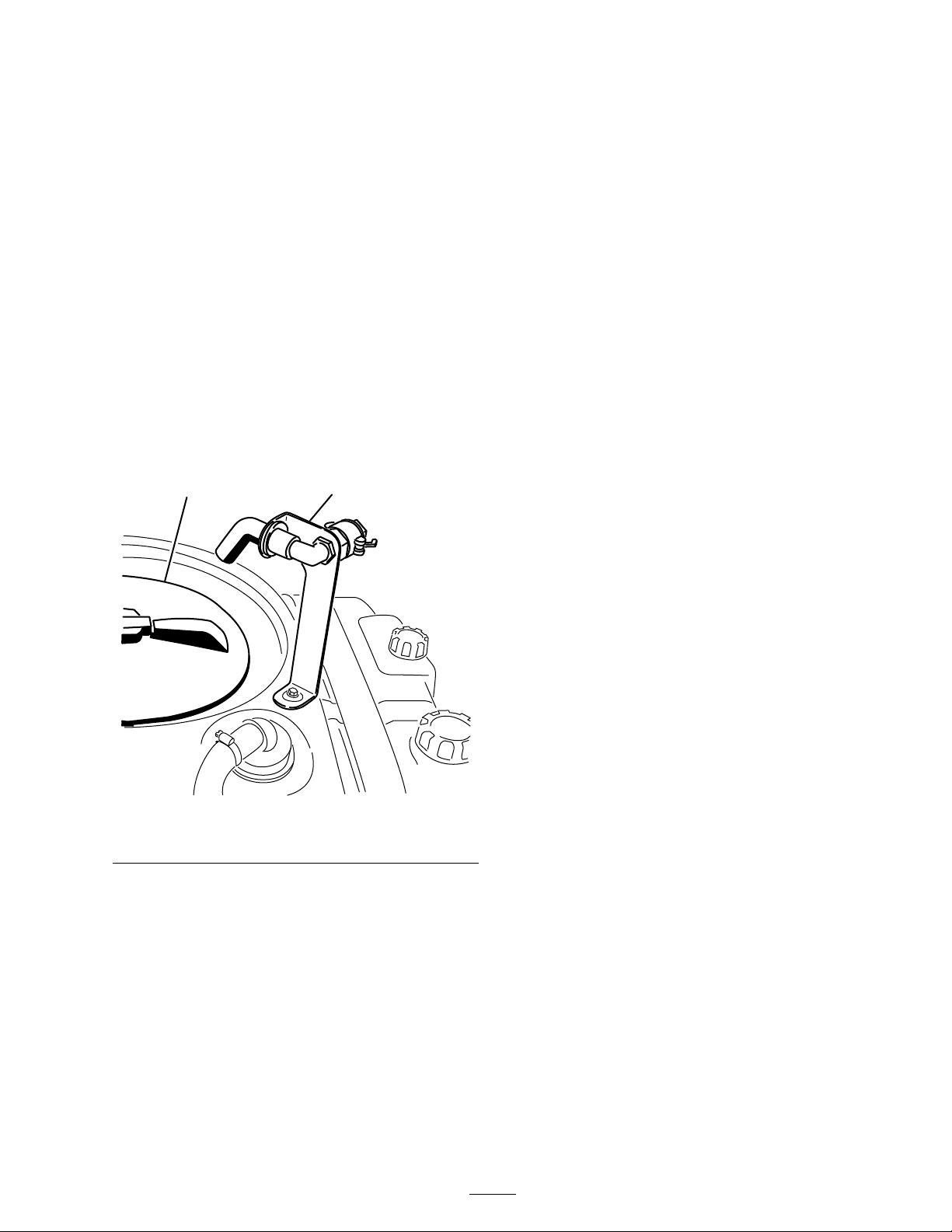
T he tank co v er is located in the center of the
top of the tank ( Figure 25 ). T o open it, tur n
the front half of the co v er countercloc kwise
and swing it open. Y ou can remo v e the strainer
inside for cleaning . T o seal the tank, close the
co v er and rotate the front half cloc kwise .
Operating the Booms
T he boom lift switc hes on the spra yer control
panel allo ws y ou to mo v e the booms betw een
transpor t position and spra y position without
lea ving the Operator’ s seat. It is recommended
to c hang e boom positions while the mac hine is
stationar y .
T o c hang e the boom position:
1. Stop the spra yer on lev el g round.
2. Use the boom lift switc hes to lo w er booms .
W ait until the booms reac h the full, extended
spra y position.
3. W hen the booms need to be retracted, stop the
spra yer on lev el g round.
4. Use the boom lift switc hes to raise the booms .
Raise the booms until they ha v e mo v ed
completely into boom transpor t cradle for ming
the “X” transpor t position and the boom
cylinders are fully retracted.
Figure 25
1. Tank cover 2. Anti-siphon ll receptacle
Important: T o pr ev ent dama ge to
the boom actuator cylinder , mak e sur e
the actuator s ar e full y r etracted bef or e
5. Add 3/4 of the required w ater to the spra y
tank using the anti-siphon fill rece ptacle .
transpor t.
The Boom Transport Cradle
Important: Al w ays use fr esh clean w ater
in the spray tank. Do not pour concentrate
into an empty tank.
6. Star t the engine , press the accelerator pedal to
the floor , and set the neutral engine speed loc k
to the On position.
7. Set the pump switc h to the On position.
8. Set the master boom switc h to the Off position.
T he spra yer is equipped with a boom transpor t
cradle that has a unique safety feature . In the ev ent
of accidental boom contact with a lo w o v erhead
object while in the transpor t position, the boom(s)
can be pushed out of the transpor t cradles . If
this occurs , the booms will come to rest in a near
horizontal position to the rear of the v ehicle .
W hile the booms will not be damag ed due to this
T he Spra y Pro monitor will displa y “HOLD”.
29
Page 30

mo v ement, they should be immediately put bac k
into the transpor t cradle .
D . R etur n to the location where spra ying is
to begin.
Important: T he booms can be dama ged by
transpor ting them in an y position other than
the “X” transpor t position using the boom
transpor t cradle.
T o put the booms bac k into the transpor t cradle ,
lo w er the boom(s) to the spra y position, and then
raise the boom(s) bac k into the transpor t position.
Mak e sure the boom cylinders are fully retracted
to prev ent actuator rod damag e .
Spraying
Important: In order to ensur e that y our
solution r emains w ell mix ed, use the a gitation
featur e whenev er y ou ha v e solution in the
tank. F or a gitation to w or k, the pump must
be on and the engine must be r unning a bo v e
an idle. If y ou stop the v ehicle and need
a gitation on, place the range selector in the
Neutral position, set the par king brak e, pr ess
the accelerator pedal to the floor , tur n on the
pump , and tur n the neutral engine speed lock
On.
Note: T his procedure assumes that the pump is
on from the Filling the Spra y T ank procedure .
1. Lo w er the booms into position.
2. Set the master boom switc h to the Off position.
T he Spra y Pro monitor will displa y “HOLD”.
3. Set the indi vidual boom switc hes , as needed, to
the On positions .
6. Set the master boom switc h to the On position
to begin spra ying .
Note: W hen the tank is nearly empty , the
agitation ma y cause foaming in the tank. In
this case , tur n the agitation control v alv e to the
3 o’cloc k position to tur n it off . Alter nati v ely ,
y ou can use an anti-foaming ag ent in the tank
(if compatible with the c hemical y ou are using).
7. W hen finished spra ying, set the master boom
switc h to the Off position to tur n off all
booms , then set the pump switc h to the Off
position.
Spraying Tips
• Do not o v erlap areas that y ou ha v e previously
spra yed.
• W atc h for plug g ed nozzles . R e place all w or n
or damag ed nozzles .
• Use the master boom switc h to stop the
spra y flo w before stopping the spra yer . Once
stopped, place the rang e selector in neutral and
use the neutral engine speed loc k to hold the
engine speed up to k ee p the agitation r unning .
• Y ou will obtain better results if the spra yer is
mo ving when y ou tur n the booms on.
• W atc h for c hang es in the application rate that
ma y indicate that y our speed has c hang ed
bey ond the rang e of the nozzles or there is a
problem with the spra y system.
4. Dri v e to the location where y ou will be
spra ying .
5. T ur n the Spra y Pro selection dial to the
Application Rate position and use the
application rate switc h to ac hiev e the desired
rate . T o do this:
A. Ensure the pump is On.
B . With the brak e pressed, select the desired
g ear rang e then begin dri ving at maxim um
speed.
C . V erify the monitor displa ys the cor rect
application rate . If needed, manipulate the
application rate switc h until the monitor
displa ys the desired application rate .
Cleaning the Sprayer
Important: Y ou must al w ays empty and
clean the spray er immediatel y after each use.
F ailur e to do so may cause the chemicals to
dr y or thick en in the lines, clo g ging the pump
and other components.
T he rinse tank is located at the front, right side
of the tank ( Figure 26 ). If y ou install the optional
Rinse Kit, y ou can fill this tank with fresh w ater
and automatically rinse the main tank, boom
supply lines and nozzles .
30
Page 31
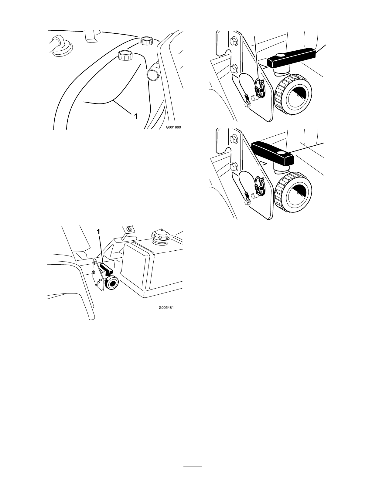
Figure 26
G005482
2
3
1
1. Rinse tank (for use with the optional rinse kit, 106-4842)
1. Stop the spra yer , set the parking brak e , place
the rang e selector in the Neutral position, and
tur n off the engine . T he tank will drain to left
side of the mac hine .
2. Locate the tank drain v alv e on the left side of
the mac hine ( Figure 27 ). T he v alv e is on the
frame in front of the fuel tank.
Figure 28
1. Valve open 3. Valve closed
2. Lynch pin
3. W hen the tank has drained completely , install
the v alv e to frame with the lync h pin remo v ed
previously and close the drain v alv e ( Figure 28 ).
Figure 27
1. Tank drain handle
Open the v alv e to drain any un used material
from the tank and dispose of it according to
local codes and the material man ufacturer’ s
instr uctions ( Figure 28 ). After draining,
remo v e the lync h pin on the brac k et securing
the drain v alv e to the mac hine and let the v alv e
rest on the g round . T his allo ws any residual
material in the line to drain.
4. Fill the tank with at least 50 US g allons (190 L)
of clean fresh w ater and close the co v er .
Note: Y ou can use a cleaning/neutralizing
ag ent in the w ater as needed. On the final
rinse , use only clean, clear w ater .
5. Star t the engine .
6. With the rang e selector in the Neutral position,
press the accelerator pedal to the floor and set
the neutral engine speed loc k switc h to the On
position.
7. Ensure that the agitation control v alv e is in the
On position.
8. Set the pump switc h to the On position and
use the application rate switc h to increase the
pressure to a high setting .
9. Set the master boom switc h and boom control
switc hes to the On positions to begin spra ying .
31
Page 32

10. Allo w all of the w ater in the tank to spra y out
though the nozzles .
11. Chec k the nozzles to ensure that they are all
spra ying cor rectly .
12. Set the master boom switc h to the Off
position, set the pump switc h to the Off
position, and stop the engine .
13. R e peat ste ps 4 through 12 at least 2 more times
to ensure that the spra y system is fully cleaned.
On the last cycle , r un the last few g allons of
w ater through the drain v alv e to clear the drain
tubing .
14. Clean the strainer; refer to Cleaning the Suction
Strainer in Cleaning , pag e 59 .
Important: If y ou used w etta ble po w der
chemicals, clean the strainer after each
tank.
15. Using a g arden hose , spra y off the outside of
the spra yer with clean w ater .
16. R emo v e the nozzles and clean them b y hand.
R e place damag ed or w or n nozzles .
32
Page 33
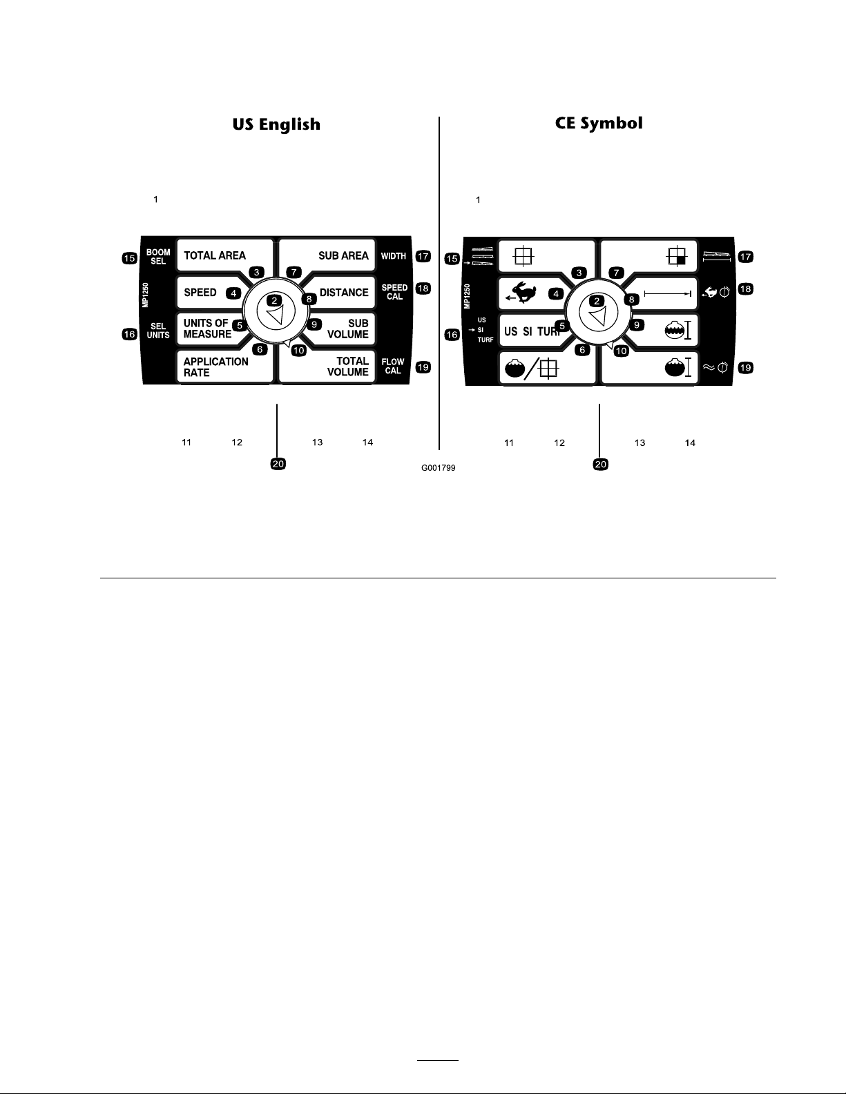
Calibrating the Spray Pro
Monitor
Figure 29
1. LCD screen
2. Selection dial
3. Total area 8. Sub Area 13. Decrease, calibration button 18. Speed calibration
4. Speed 9. Sub volume 14. Increase, calibration button 19. Flowmeter calibration
5. Units of measure 10. Total volume 15. Boom selection
T he Spra y Pro monitor has a calibration mode that
allo ws y ou to c hang e v arious settings to customize
the displa y and calibrate the monitor to y our needs .
Y ou can calibrate or c hang e the follo wing settings:
• Boom Width
• Units of Measure
• Speed
• Flo wmeter
6. Application rate 11. Reset, calibration button 16. Select units
7. Distance
12. Calibrate, calibration button 17. Width
20. LED
3. Press and hold the Calibrate button until the
monitor displa ys “CAL HOLD” and the red
light on the monitor illuminates .
4. T ur n the selection dial to the T otal Area
position.
5. Use the Increase or Decrease calibration
buttons to select the boom for whic h y ou wish
to c hang e the width, where 1 is the left boom,
2 is the center boom, and 3 is the right boom.
Setting the Boom Width
T he default settings for the boom widths are 80
inc hes (2.03 m) for the right and left booms and
60 (1.524 m) for the center boom. T his is based
6. T ur n the selection dial to the Sub Area
position.
7. Use the Increase or Decrease calibration
buttons to c hang e the boom width as needed.
on 4 nozzles on the right and left booms and 3 on
the center boom all spaced 20 inc hes (50.8 cm)
apar t. If y ou c hang e the spacing of the nozzles ,
y ou should c hang e the boom width to reflect y our
c hang es as follo ws:
1. Stop the spra yer and set the parking brak e .
8. R e peat ste ps 4 through 7 for the other booms
as needed.
9. Press the Calibrate button until the red light
tur ns off . Y ou can also exit the calibration
mode b y dri ving the spra yer .
2. Set the master boom switc h to the Off
position. T he monitor displa ys “HOLD”.
33
Page 34

Setting the Units of Measure
T he default setting for the units of measure is
US . Y ou can also c hang e the units to SI (metric)
or TURF .
1. Stop the spra yer and set the parking brak e .
2. Set the master boom switc h to the Off
position. T he monitor displa ys “HOLD”.
3. Press and hold the Calibrate button until the
monitor displa ys “CAL HOLD” and the red
light on the monitor illuminates .
4. T ur n the selection dial to the Units of Measure
position.
5. Use the Increase or Decrease calibration
buttons to select desired units of measure .
6. Press the Calibrate button until the red light
tur ns off . Y ou can also exit calibration mode
b y dri ving the spra yer .
Calibrating the Flowmeter
T he Spra y Pro monitor comes appro ximately
calibrated for the flo wmeter . Complete the
follo wing procedure to fine tune the flo wmeter
calibration:
1. Set the parking brak e .
8. Compare the v olume displa yed on the monitor
to the v olume of w ater y ou put into the tank.
• If the v olumes are the same , y ou do not
need to calibrate the monitor any fur ther .
• If the v alues are different, contin ue with
the rest of this procedure .
9. With the selection dial set to the T otal V olume
position, press and hold the Calibrate button
until the monitor displa ys “CAL HOLD” and
the red light on the monitor illuminates .
T he displa y will alter nate betw een the total
v olume reading (“HOLD” sho wn) and the
flo w calibration v alue (“CAL HOLD” sho wn).
10. W hen the total v olume v alue is displa yed, use
the Increase or Decrease calibration buttons
to c hang e it to the amount of w ater y ou put
in the tank.
11. W hen the displa y begins alter nating ag ain, the
flo w calibration v alue will ha v e c hang ed; write
this n umber do wn and sa v e it. T his is the
calibration v alue for y our spra yer .
12. Press the Calibrate button until the red light
tur ns off . Y ou can also exit calibration mode
b y dri ving the spra yer .
2. Fill the spra yer tank with a kno wn quantity of
w ater , at least 100 US g allons (380 L).
Note: Do not rely on the marks on the
side of the tank for measuring the w ater
for this procedure . T hey are appro ximate
measurements , but not accurate enough for
this calibration.
3. Set the pump switc h to the On position to
star t the pump .
4. Set all three boom switc hes and the master
boom switc h to the On position. R un the
booms only until the air is purg ed from the
line , then tur n them off using the master boom
switc h.
5. T ur n the selection dial to the T otal V olume
position.
6. Press and hold the R eset calibration button
until the displa y reads “0”.
7. Set the master boom switc h to the On position
and r un the booms until all the w ater is out
of the tank, then stop them using the master
boom switc h.
Calibrating the Speed Sensor
T he Spra y Pro comes appro ximately calibrated
for the speed sensor . Complete the follo wing
procedure to fine tune the speed sensor calibration:
1. Chec k and fill all tires; refer to Chec king
Tire Pressure in Dri v e System Maintenance ,
pag e 51 .
2. Fill the fresh w ater tank.
3. Fill the spra yer tank half-full of w ater .
4. Select a straight, flat trac k of g round that is
similar to y our turf conditions .
Note: Using a road or other pa v ed surface
could cause an inaccurate reading when y ou
later dri v e the spra yer on turf .
5. Measure 500 feet (150 m), marking both the
star t and end points .
6. P osition the spra yer at the star ting point.
7. Set the pump and the master boom switc hes to
the Off position. T he monitor should displa y
“HOLD”.
34
Page 35

8. T ur n the selection dial to the Distance position.
9. Press and hold the R eset calibration button
until the displa y reads “0”.
10. W hen y ou reac h the star t point, press the
master boom switc h to star t the distance
trac king with the monitor . Dri v e the mac hine
from the star t point y ou mark ed to the 500 feet
(150 m) end point.
v alv es so that the pressure and application rate
remains the same for all booms when y ou tur n one
or more booms off .
Note: T he boom b ypass v alv es m ust be
calibrated eac h time the nozzles are c hang ed.
Select an open flat area to perfor m this procedure .
1. Fill the spra y tank with clean w ater .
11. W hen y ou reac h the end point, set the master
boom switc h to the Off position to stop the
monitor .
12. Look at the distance displa yed on the monitor .
• If it reads “500 feet (150 m)”, y ou do not
need to calibrate the monitor any fur ther .
• If it does not read “500 feet (150 m)”,
contin ue with the rest of this procedure .
13. Set the parking brak e .
14. With the selection dial set to the Distance
position, press and hold the Calibrate button
until the monitor displa ys “CAL HOLD” and
the red light on the monitor illuminates .
T he displa y will alter nate betw een the distance
v alue (“HOLD” sho wn) and the speed
calibration v alue (“CAL HOLD” sho wn).
15. W hen the distance v alue is displa yed, use the
Increase or Decrease calibration buttons to
c hang e it to 500 feet (150 m).
16. W hen the displa y begins alter nating ag ain,
the speed calibration v alue will ha v e c hang ed;
write this n umber do wn and sa v e it. T his is the
calibration v alue for y our spra yer .
17. Press the Calibrate button until the red light
tur ns off . Y ou can also exit calibration mode
b y dri ving the spra yer .
2. Put the extension booms do wn, if installed.
3. Set the parking brak e and star t the engine .
4. Set the dial on the Spra y Pro monitor to
Application Rate .
5. Place the rang e selector in the Neutral position.
6. Press the accelerator to the floor and set the
neutral engine speed loc k switc h to the On
position.
7. Set the pump switc h to the On position to
star t the pump .
8. Set all three boom switc hes and the master
boom switc h to the On position.
9. Use the application rate switc h to adjust the
pressure as read on the pressure g aug e until it
is in the rang e for the nozzles y ou installed on
the booms (typically 40 psi/2.75 bar).
10. R ecord the reading on the pressure g aug e .
11. T ur n off one of the booms using the
appropriate boom switc h.
12. Adjust the boom b ypass v alv e ( Figure 30 )
under the boom control v alv e for the boom
y ou tur ned off until the pressure reading on
the g aug e is the same as it w as in ste p 9 .
Resetting an OFL Condition
If the monitor reads “OFL ”, it indicates that y ou
ha v e ex ceeded the monitor screen dimensions .
Press and hold the R eset calibration button to set
the displa y to 0.
Calibrating the Boom Bypass
Valves
Before using the spra yer for the first time or if
the nozzles are c hang ed, adjust the boom b ypass
35
Page 36
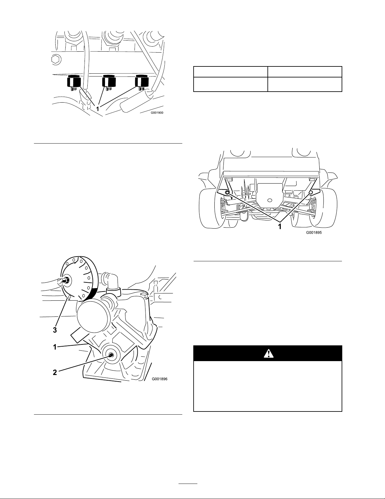
recommended for nozzle spra y pressures betw een
20 psi (1.3 bar) and 45 psi (3 bar). If different
nozzle pressures are required, set pressure
dampener at pressures indicated.
Figure 30
1. Boom bypass valves
13. T ur n the boom on and off to v erify the
pressure does not c hang e .
14. R e peat ste ps 11 through 13 for the other
booms .
15. Dri v e the spra yer at the desired speed while
spra ying and tur n eac h boom off indi vidually .
T he pressure on the g aug e should not c hang e .
Pump
T he pump is located near the front of the tank on
the right side ( Figure 31 ).
Nozzle
40 psi/2.7 bar 12–14 psi/0.8–0.9 bar
Dampener
Transporting the Sprayer
F or mo ving the spra yer long distances , use a
trailer . Secure the spra yer to the trailer . Figure 32
illustrates the front tie-do wn points .
Figure 32
1. Tie down points
Figure 31
1. Pump
2. Grease tting
3. Pressure dampener
Adjusting the Air Pressure in
Dampener
T he air pressure in the dampener on the pump is
set at 15 psi (1 bar) b y the man ufacturer . T his is
T he rear tie-do wn points are tw o steel loops under
the bac k of the frame just in front of the adjustable
boom frame .
Towing the Sprayer
In case of an emerg ency , the spra yer can be
to w ed for a shor t distance . Ho w ev er , w e do not
recommend this as a standard procedure .
T o wing at ex cessi v e speeds could cause a
loss of steering contr ol, r esulting in per sonal
injur y .
Nev er to w the spray er f aster than 5 mph
(8 kph).
T o wing the spra yer is a tw o person job . If
the mac hine m ust be mo v ed a considerable
distance , transpor t it on a tr uc k or trailer; refer to
T ranspor ting the Spra yer .
1. Affix a to w line to the frame .
36
Page 37

2. Put the rang e selector in the Neutral position
and release the parking brak e .
3. T o w the spra yer at less than 5 mph (8 kph).
37
Page 38
Maintenance
Note: Deter mine the left and right sides of the mac hine from the nor mal operating position.
Recommended Maintenance Schedule(s)
Maintenance Service
Interval
After the rst 8 operating
hours
After the rst 50
operating hours
Before each use or daily
Every 25 hours
Every 50 hours
Every 100 hours
Maintenance Procedure
• Torque the wheel lug nuts.
• Check the drive belt tension.
• Check the steering pump belt.
• Replace the hydraulic lter.
• Change the engine oil.
• Check the engine oil.
• Check the tire pressure.
• Clean the suction strainer (more often when using wetable powders).
• Clean and oil the foam air cleaner (more often in dusty, dirty conditions).
• Lubricate the pump.
• Check the battery cable connections.
• Check the battery electrolyte level.
• Lubricate the grease ttings.
• Lubricate the boom hinges.
• Clean the engine rotating screen (more often in dusty, dirty conditions).
• Replace the paper air cleaner element (more often in dusty, dirty
conditions).
• Change the engine oil, including synthetic oil (more often when operating
under heavy load or in high temperature).
• Replace the engine oil lter.
• Replace the fuel lter.
• Check the operation of the Neutral gear shift position.
• Inspect the condition and wear of the tires.
• Torque the wheel lug nuts.
• Check front wheel toe-in.
• Inspect the brakes.
• Check the steering pump belt.
Every 200 hours
• Change the spark plugs.
• Check the shift cables.
• Check the parking brake.
• Check the drive belt.
• Check the transaxle/hydraulic uid.
• Inspect all hoses and connections for damage and proper attachment.
38
Page 39

Maintenance Service
Every 400 hours
Interval
Maintenance Procedure
• Grease the actuator rod bearings.
• Complete all yearly maintenance procedure specied in the engine
operator’s manual.
• Inspect the fuel lines.
• Clean and lubricate the primary drive clutch.
• Inspect the pump diaphragm and replace if necessary (see an Authorized
Toro Service Distributor).
• Inspect the pressure dampener bladder and replace if necessary (see an
Authorized Toro Service Distributor).
• Inspect the pump check valves and replace if necessary (see an Authorized
Toro Service Distributor).
• Change the pump drive gearbox uid.
• Check boom actuator hydraulic oil for air bubbles.
• Inspect the nylon pivot bushings.
• Inspect the O-rings in the valve assemblies and replace them if necessary.
Every 800 hours
Yearly
• Change the transaxle/hydraulic uid.
• Replace the hydraulic lter.
• Grease the actuator rod bearings.
• Complete all yearly maintenance procedure specied in the engine
operator’s manual.
• Inspect the fuel lines.
• Clean and lubricate the primary drive clutch.
• Change the transaxle/hydraulic uid.
• Replace the hydraulic lter.
• Inspect the pump diaphragm and replace if necessary (see an Authorized
Toro Service Distributor).
• Inspect the pressure dampener bladder and replace if necessary (see an
Authorized Toro Service Distributor).
• Inspect the pump check valves and replace if necessary (see an Authorized
Toro Service Distributor).
• Change the pump drive gearbox uid.
• Inspect the nylon pivot bushings.
• Inspect the O-rings in the valve assemblies and replace them if necessary.
Important: R efer to y our engine Operator’ s Man ual f or additional maintenance pr ocedur es.
39
Page 40
Daily Maintenance Checklist
Duplicate this page for routine use.
Maintenance Check Item
Check the brake and parking brake
operation.
Check the gear shift/neutral
operation.
Check the fuel level.
Check the engine oil level.
Check the transaxle oil level.
Inspect the air lter.
Inspect the engine cooling ns.
Check any unusual engine noises.
Check any unusual operating noises.
Check the tire pressure.
Check for uid leaks.
Check the instrument operation.
Check the accelerator operation.
Clean the suction strainer.
Check toe-in.
Lubricate all grease ttings.
Touch up and damaged paint.
For the week of:
Mon. Tues.
1
Wed. Thurs.
Fri.
Sat. Sun.
1
Immediately after every washing, regardless of the interval listed
Notation for Areas of Concern
Inspection performed by:
Item Date
1
2
3
4
5
6
7
8
9
10
11
12
Information
40
Page 41
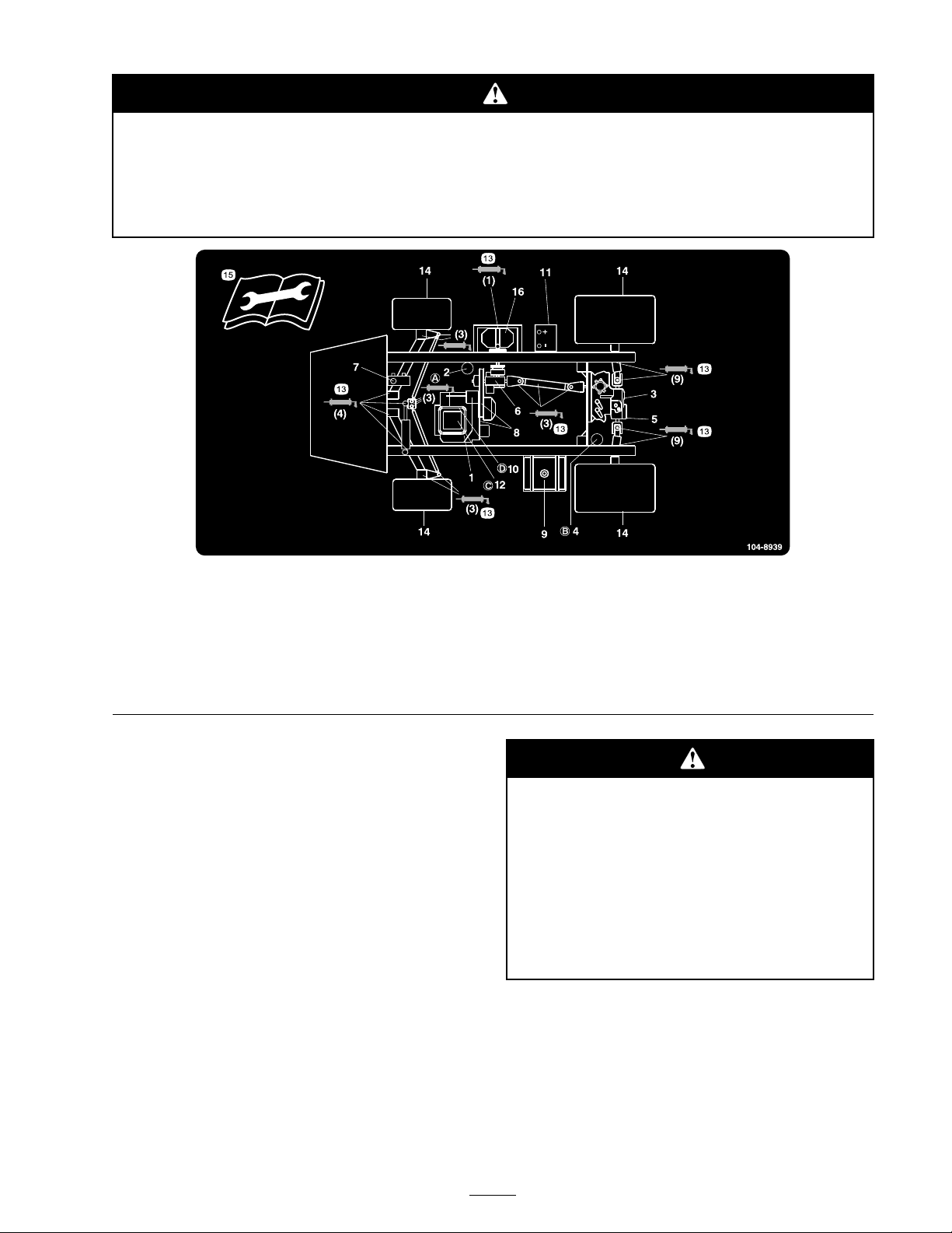
If y ou lea v e the k ey in the ignition s witch, someone could accidentl y star t the engine and
seriousl y injur e y ou or other bystander s.
R emo v e the k ey fr om the ignition and disconnect the wir e(s) fr om the spar k plug(s) bef or e
y ou do an y maintenance. Set the wir e(s) aside so that it does not accidentall y contact the
spar k plug(s).
Figure 33
Service locations
1. Engine oil level (dipstick)
2. Engine oil lter 6. Gear box uid level 10. Fuel lter
3. Transaxle/hydraulic uid
level (dipstick)
4. Transaxle hydraulic lter 8. Belts, steering and drive 12. Air cleaner
5. Hydraulic strainer 9. Fuel, unleaded only
7. Brake uid
11. Battery
Premaintenance
Procedures
Jacking the Sprayer
W henev er the engine is r un for routine
maintenance and/or engine diagnostics , the rear
wheels of the spra yer should be 1 inc h (25 mm)
off of the g round with the rear axle suppor ted on
jac k stands .
13. Grease
14. Tire pressure
15. Read the instructions before
servicing or performing
maintenance.
16. Pump
A spray er on a jack may be unsta ble and slip
of f of the jack, injuring an y one beneath it.
• Do not star t the engine while the spray er
is on a jack.
• Al w ays r emo v e the k ey fr om the ignition
bef or e getting of f of the spray er .
• Block the tir es when the spray er is on a
jack.
T he jac king point at the front of the spra yer is
under the A-ar ms ( Figure 34 )
41
Page 42
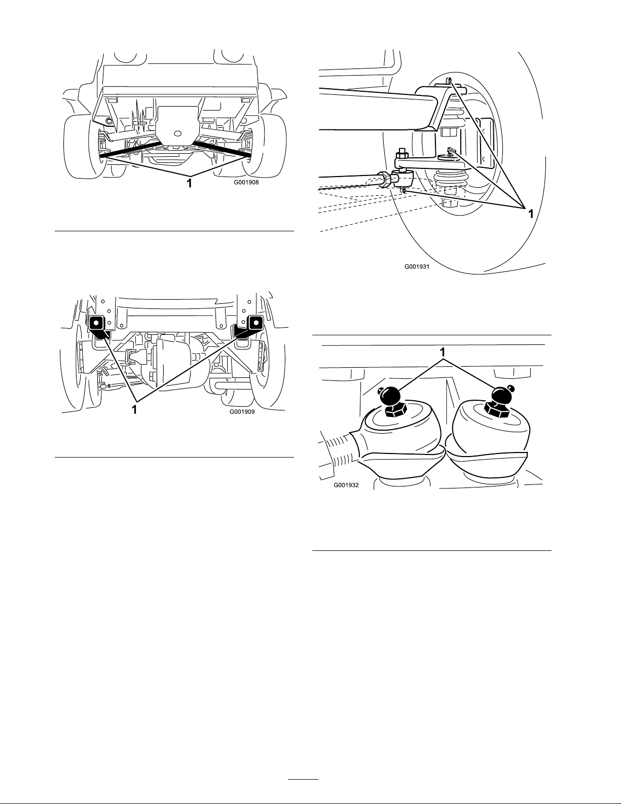
Figure 34
1. Front jacking points
T he jac king point at the rear of the spra yer is on
the rear frame suppor t, betw een the angle w elds
( Figure 35 ).
Figure 35
1. Rear jacking points
Figure 36
At the wheels, three on each side
1. Grease point
Lubrication
Greasing the Sprayer
Lubricate all bearings and bushings after ev er y
100 hours or once a year , whic hev er occurs first.
Grease T ype: No . 2 General Pur pose Lithium
Base Grease
1. Wipe the g rease fitting clean so that foreign
matter cannot be forced into the bearing or
bushing .
2. Pump g rease into the bearing or bushing .
3. Wipe off ex cess g rease .
T he g rease fittings positions are illustrated b y
the follo wing: Figure 36 through Figure 42 .
Figure 37
Steering rods
1. Grease point
42
Page 43
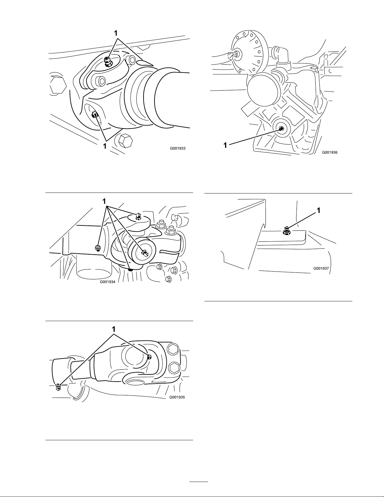
Figure 38
Pump drive, four, one each side
1. Grease point
Figure 39
Drive axel at engine, ve, one each side and slip joint
1. Grease point
Figure 41
Pump (Do not over grease)
1. Grease point
Figure 42
1. Grease point
Greasing the Boom Hinges
Important: If the boom hinge is w ashed
with w ater , all w ater and de bris must be
clear ed fr om the hinge assembl y and fr esh
g r ease must be applied.
1. Grease point
Grease T ype: No . 2 g eneral-pur pose lithium base
g rease .
1. Wipe the g rease fittings clean so that foreign
matter cannot be forced into the bearing or
Figure 40
Drive axel at transmission
bushing .
2. Pump g rease into the bearing or bushing at
eac h fitting Figure 43 .
43
Page 44
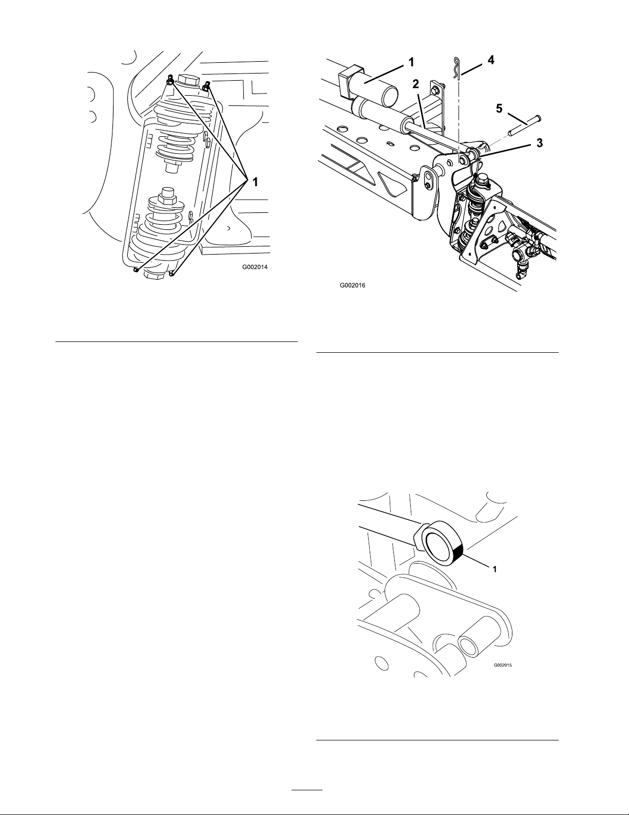
Figure 43
Right boom
1. Grease tting
3. Wipe off ex cess g rease .
4. R e peat the procedure for eac h boom pi v ot.
Greasing the Actuator Rod
Bearings
Figure 44
1. Actuator
2. Actuator rod
3. Boom pivot pin housing
4. Cotter
5. Pin
3. Lift up on the boom and remo v e the pin
( Figure 44 ). Slo wly lo w er the boom to the
g round.
4. Inspect the pin for any damag e , re place if
necessar y .
Grease the bearing end of the both boom actuator
rods at 400 hours and/or yearly .
Grease T ype: No . 2 g eneral-pur pose lithium base
g rease .
1. Extend the booms to the spra y position.
2. R emo v e the cotter pin from the pi v ot pin
( Figure 44 ).
5. Manipulate the actuator rod bearing end and
apply g rease into the bearing ( Figure 45 ). Wipe
off ex cess g rease .
Figure 45
Right boom
1. Grease bearing
44
Page 45
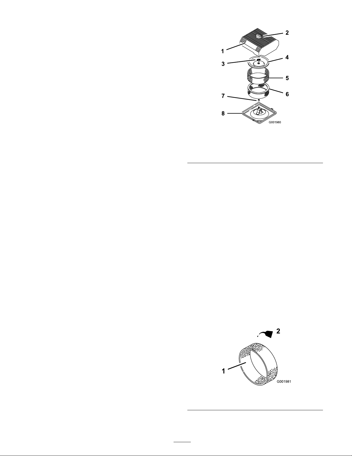
6. Raise the boom to align the pi v ot with the
actuator rod. W hile holding the boom, inser t
the pin through both boom pi v ot and actuator
rod ( Figure 44 ).
7. With the pin in place , release the boom
and secure the pin with the cotter remo v ed
previously .
8. R e peat the procedure for eac h actuator rod
bearing .
Engine Maintenance
Checking the Air Intake
Screen
Chec k and clean as necessar y the air intak e screen
on the front of the engine ev er y 8 operating hours .
Figure 46
1. Air cleaner cover 5. Foam element
2. Knob 6. Paper element
3. Cover nut
4. Cover
7. Rubber seal
8. Air cleaner base
4. Loosen the knob on the air cleaner co v er and
remo v e the co v er ( Figure 46 ).
Servicing the Air Cleaner
F oam Element: Clean and oil after ev er y 25
operating hours , or yearly , whic hev er occurs first.
P aper Element: R e place after ev er y 100 operating
hours or yearly , whic hev er occurs first.
Note: Ser vice the air cleaner more frequently
(ev er y few hours) if operating conditions are
extremely dusty or sandy .
Removing the Foam and Paper
Elements
1. Set the parking brak e , stop the pump , stop the
engine , and remo v e the ignition k ey .
2. R elease the latc h on the bac k of the seat and
lift the seat forw ard.
3. Clean around the air cleaner to prev ent dir t
from g etting into the engine and causing
damag e ( Figure 46 ).
5. Carefully slide the foam element off the paper
element ( Figure 46 ).
6. Unscrew the co v er n ut and remo v e the co v er
and paper element ( Figure 46 ).
Cleaning the Foam Element
1. W ash the foam element in liquid soap and
w ar m w ater .
2. W hen the element is clean, rinse it thoroughly .
3. Dr y the element b y squeezing it in a clean
cloth.
4. Put one or tw o ounces of oil on the element
( Figure 47 ).
Important: R eplace the f oam element
if it is tor n or w or n.
Figure 47
1. Foam element 2. Oil
5. Squeeze the element to distribute the oil.
45
Page 46
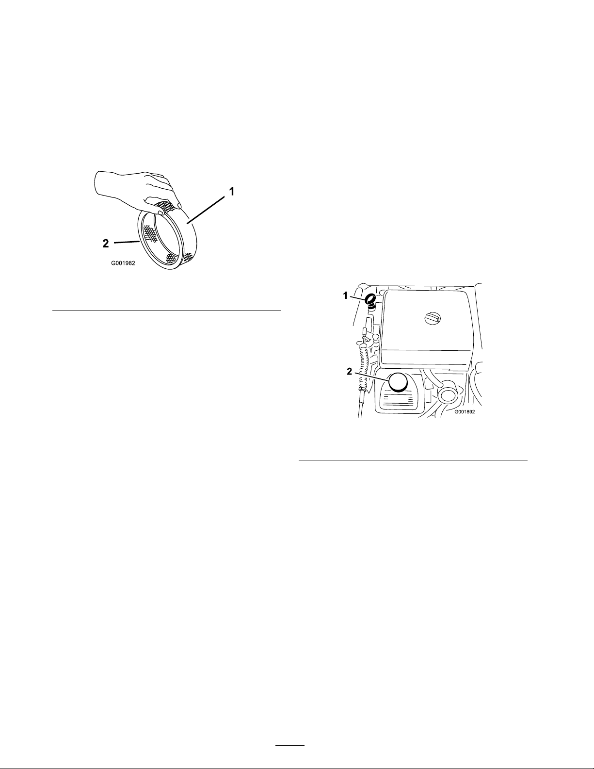
Checking the Paper Element
• Prefer red oil: SAE 10W30 (abo v e 0° F)
Inspect the paper element for tears , an oily film,
damag e to the r ubber seal, ex cessi v e dir t, or other
damag e ( Figure 48 ). If any of these conditions
exit, re place the filter .
Important: Do not clean the paper element
with pr essuriz ed air or liquids, such as solv ent,
gas, or k er osene.
Figure 48
1. Paper element 2. Rubber seal
Important: T o pr ev ent engine dama ge,
al w ays operate the engine with the complete
f oam and paper air cleaner assembl y installed.
• Alter nate oil: SAE 5W30 (belo w 32° F)
T oro Premium Engine Oil is a v ailable from y our
distributor in either 15W40 or 10W30 viscosity .
See the P ar ts Catalo g for par t n umbers .
Check the Engine Oil
T he engine is shipped with oil in the crankcase;
ho w ev er , the lev el of oil m ust be c hec k ed before
y ou first star t the engine and after y ou ha v e r un it.
1. P osition the mac hine on a lev el surface .
2. R emo v e the dipstic k and wipe it with a clean
rag ( Figure 49 ). Inser t the dipstic k into the
tube and mak e sure it is seated fully . R emo v e
the dipstic k and c hec k the oil lev el.
Installing the Foam and Paper
Elements
1. Carefully slide the foam element onto the
paper air cleaner element ( Figure 46 ).
2. Slide the air cleaner assembly and co v er onto
the long rod.
3. Install the co v er n ut fing er -tight ag ainst the
co v er ( Figure 46 ).
Note: Ensure that the r ubber seal is flat
ag ainst the air cleaner base and co v er .
4. Install the air cleaner co v er and knob
( Figure 46 ).
5. Close and latc h the seat.
Servicing the Engine Oil
Chang e the engine oil and oil filter after ev er y 100
operating hours .
Crankcase Capacity is 2.1 qt (2.0 l) with the filter .
Use high-quality engine oil that meets the follo wing
specifications:
• API classification Lev el required: SJ , JK, SL,
or higher .
Figure 49
1. Dipstick 2. Filler cap
3. If the oil lev el is lo w , remo v e the filler cap from
the v alv e co v er ( Figure 49 ) and pour oil into
the opening until the oil lev el is up to the Full
mark on the dipstic k. Add the oil slo wly and
c hec k the lev el often during this process . Do
not o v erfill.
4. Install the dipstic k fir mly in place .
Changing the Engine Oil
1. Star t the engine and let it r un for fiv e min utes .
T his w ar ms the oil so it drains better .
2. Set the parking brak e , stop the pump , stop the
engine , and remo v e the ignition k ey .
3. R elease the latc h on the bac k of the seat and
lift the seat forw ard.
46
Page 47
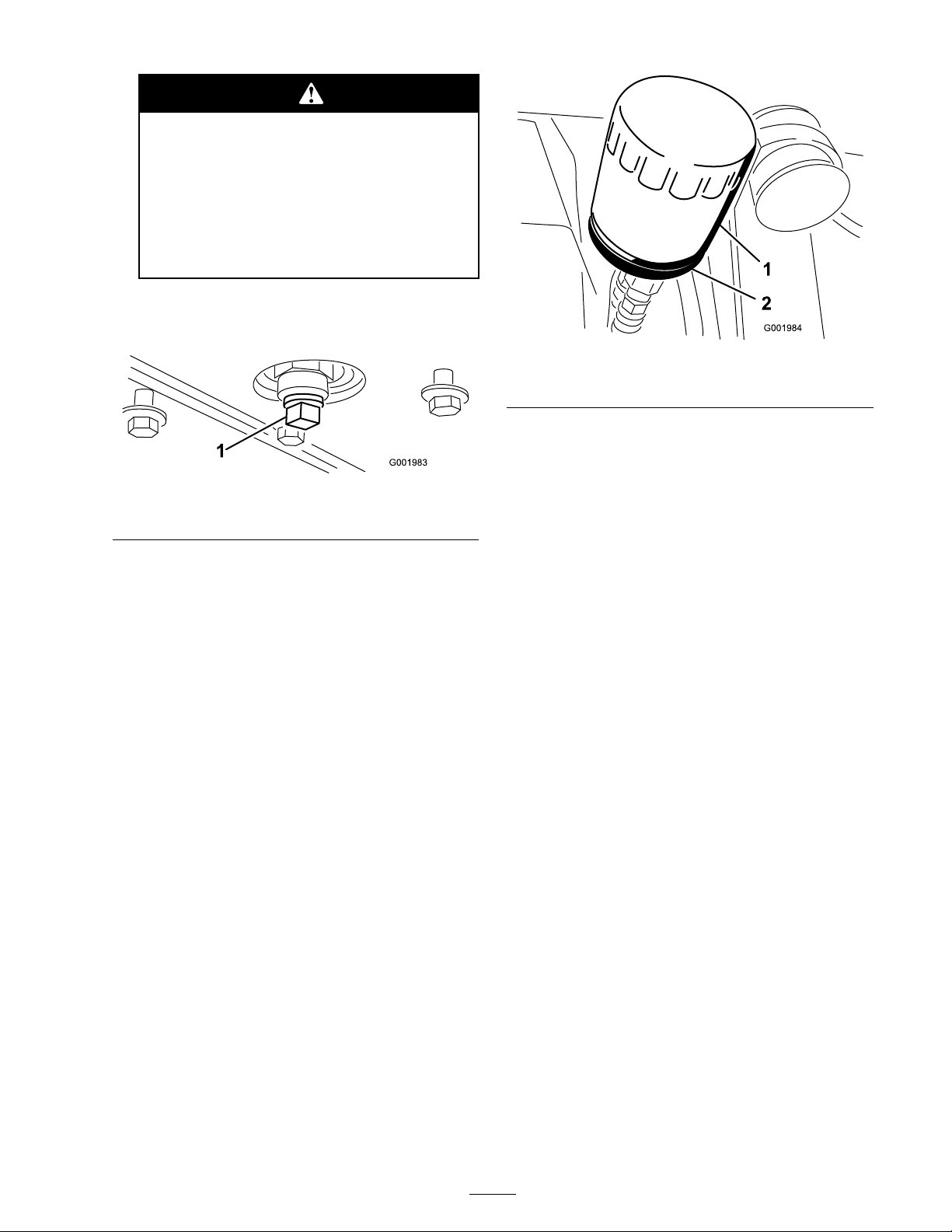
Components under the seat will be
hot if the spray er has been r unning . If
y ou touch hot components y ou may be
bur ned.
Allo w the spray er to cool bef or e
perf or ming maintenance or touching
components under the hood.
4. Place a pan belo w the oil drain.
5. R emo v e the drain plug ( Figure 50 ).
Figure 50
1. Oil drain plug
6. W hen the oil has drained completely , re place
the drain plug and tor que it to 10 ft-lb (13.6
N ⋅ m).
7. Dispose of the used oil at a cer tified recycling
center .
8. Slo wly pour appro ximately 80% of the
specified amount of oil into the oil filler tube
( Figure 49 ).
Figure 51
1. Oil lter 2. Filter adapter
3. Wipe the filter adapter g ask et surface .
4. Apply a thin coat of new oil to the r ubber
g ask et on the re placement filter .
5. Install the re placement oil filter to the filter
adapter . T ur n the oil filter cloc kwise until
the r ubber g ask et contacts the filter adapter ,
then tighten the filter an additional 1/2 tur n
( Figure 51 ).
6. Fill the crankcase with the cor rect type of new
oil; refer to Changing the Engine Oil, ste ps 8
through 10 .
7. Dispose of the used oil filter at a cer tified
recycling center .
9. Chec k the oil lev el.
10. Slo wly add additional oil to bring the oil lev el
to the full mark on the dipstic k.
Important: Ov erfilling the crankcase
with oil may cause engine dama ge.
Changing the Engine Oil Filter
1. Drain the oil from the engine; refer to
Changing the Engine Oil.
2. R emo v e the oil filter ( Figure 51 ).
Changing the Spark Plugs
Chang e the spark plugs after ev er y 200 operating
hours . Mak e sure the air g ap betw een the center
and side electrodes is cor rect before installing the
spark plugs . Use a spark plug wrenc h for remo ving
and installing the spark plugs and a g apping
tool/feeler g aug e to c hec k and adjust the air g ap .
T ype: Champion R C-12Y C (or equi v alent) Air
Gap: 0.030 inc h (0.76 mm)
Removing the Spark Plug
1. Set the parking brak e , stop the pump , stop the
engine , and remo v e the ignition k ey .
2. R elease the latc h on the bac k of the seat and
lift the seat forw ard.
3. Pull the wires off the spark plugs ( Figure 52 ).
47
Page 48
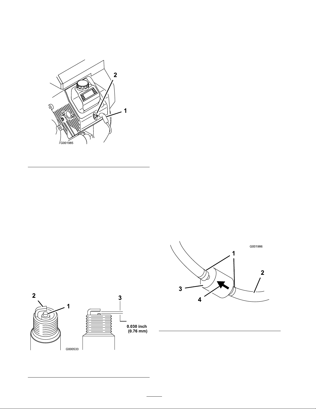
4. Clean around the spark plugs to prev ent dir t
from falling into the engine and potentially
causing damag e .
5. R emo v e the spark plugs and metal w ashers .
Figure 52
1. Spark plug wire 2. Spark plug
Checking the Spark Plugs
1. Look at the center of the spark plugs
( Figure 53 ).
If y ou see a light bro wn or g ra y coating on the
insulator , the engine is operating properly . A
blac k coating on the insulator usually means
the air cleaner is dir ty .
Important: Do not clean the spar k
plugs. Al w ays r eplace a spar k plug when it
has a black coating , w or n electr odes, an
oil y film, or cracks.
Installing the Spark Plugs
1. Install the spark plugs and metal w ashers .
2. Tighten the spark plugs to 18 to 22 ft-lb (24.4
to 29.8 N ⋅ m).
3. Push the wires onto the spark plugs ( Figure 52 ).
4. Close and latc h the seat.
Fuel System
Maintenance
Replacing the Fuel Filter
R e place the fuel filter after ev er y 100 operating
hours .
1. Set the parking brak e , stop the pump , stop the
engine , and remo v e the ignition k ey .
2. R elease the latc h on the bac k of the seat and
lift the seat forw ard.
3. Clamp off the hose on either side of the fuel
filter to prev ent g as from pouring out of the
hoses when y ou remo v e the filter .
4. Place a drain pan under the filter .
5. Squeeze the ends of the hose clamps tog ether
and slide them a w a y from the filter ( Figure 54 ).
6. R emo v e the filter from the fuel lines .
2. Chec k the g ap betw een the center and side
electrodes ( Figure 53 ) and bend the side
electrode , if the g ap is not cor rect.
Figure 53
1. Center electrode insulator
2. Side electrode
3. Air gap (not to scale)
Figure 54
1. Hose clamp 3. Filter
2. Fuel line 4. Flow direction arrow
7. Install a new filter and mo v e the hose clamps
close to the filter .
Ensure that the flo w direction ar ro w points
to w ard the engine .
48
Page 49
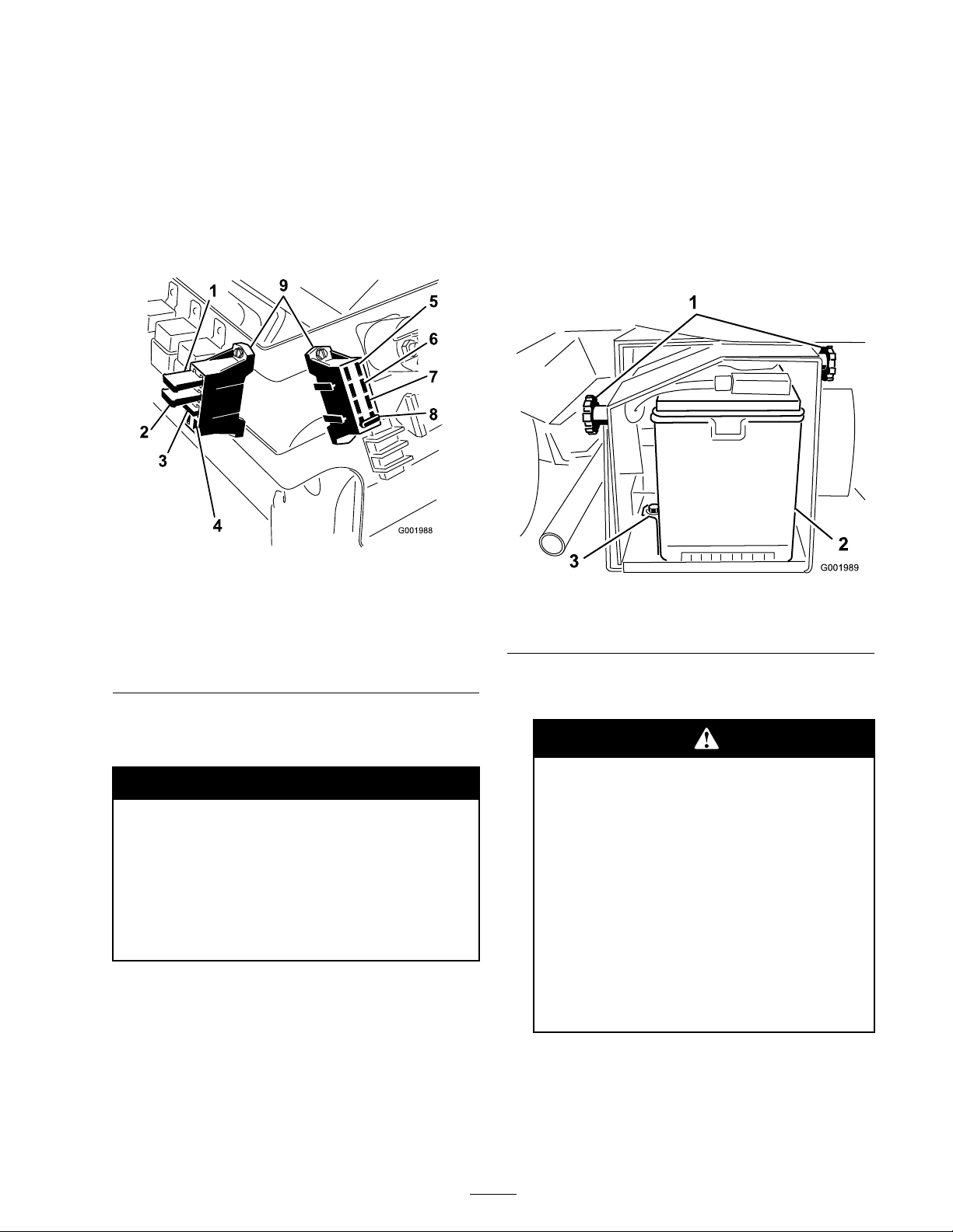
Electrical System
Maintenance
V oltag e: 12 v olt with 280 cold cranking Amps @
0° F
Removing the Battery
Replacing the Fuses
T here are 2 fuse bloc ks and 1 empty slot in the
electrical system. T hey are located beneath the
seat ( Figure 55 ).
Figure 55
1. Left boom actuator thermal
breaker
2. Right boom actuator
thermal breaker
3. Foam marker
4. Open slot 9. Fuse blocks
5. Power
6. Headlights
7. Cruise control
8. Spray system
1. P osition the spra yer on a lev el surface , set the
parking brak e , stop the pump , stop the engine ,
and remo v e the ignition k ey .
2. Loosen the knobs on the sides of the batter y
bo x and remo v e the batter y co v er ( Figure 56 ).
Figure 56
1. Knobs
2. Battery
3. Retainer
3. Disconnect the neg ati v e (blac k) g round cable
from the batter y post.
Servicing the Battery
Warning
CALIFORNIA
Pr oposition 65 W ar ning
Batter y posts, ter minals, and r elated
accessories contain lead and lead
compounds, chemicals kno wn to the State of
Calif or nia to cause cancer and r epr oducti v e
har m. W ash hands after handling .
Important: Do not jump star t the spray er .
Alw a ys k ee p the batter y clean and fully c harg ed.
Use a paper to w el to clean the batter y and batter y
bo x. If the batter y ter minals are cor roded, clean
them with a solution of four par ts w ater and one
par t baking soda. Apply a light coating of g rease
to the batter y ter minals to prev ent cor rosion.
Incor r ect batter y ca ble r outing could
dama ge the spray er and ca bles causing
spar ks. Spar ks can cause the batter y
gasses to explode, r esulting in per sonal
injur y .
• Al w ays disconnect the negati v e
(black) batter y ca ble bef or e
disconnecting the positi v e (r ed)
ca ble.
• Al w ays r econnect the positi v e (r ed)
batter y ca ble bef or e r econnecting the
negati v e (black) ca ble.
49
Page 50

Batter y ter minals or metal tools could
shor t a gainst metal spray er components
causing spar ks. Spar ks can cause the
batter y gasses to explode, r esulting in
per sonal injur y .
• W hen r emo ving or installing the
batter y , do not allo w the batter y
ter minals to touch an y metal par ts of
the spray er .
• Do not allo w metal tools to shor t
betw een the batter y ter minals and
metal par ts of the spray er .
• Al w ays k eep the batter y strap in place
to pr otect and secur e the batter y .
4. Disconnect the positi v e (red) cable from the
batter y post.
5. R emo v e the batter y retainer and fasteners
( Figure 56 ).
6. R emo v e the batter y .
Installing the Battery
1. Set the batter y on the batter y bo x so that
the batter y posts are to w ard the front of the
spra yer .
2. Install the batter y retainer and secure it with the
fasteners y ou remo v ed previously ( Figure 56 ).
distilled w ater; refer to Adding W ater to the
Batter y .
Batter y electr ol yte contains sulfuric acid
which is a deadl y poison and causes
sev er e bur ns.
• Do not drink electr ol yte or allo w it to
contact y our skin, ey es or clothing .
W ear safety g lasses to shield y our
ey es and r ub ber g lo v es to pr otect y our
hands.
• Fill the batter y wher e clean w ater is
al w ays a v aila ble f or flushing the skin.
Adding Water to the Battery
T he best time to add distilled w ater to the batter y is
just before y ou operate the mac hine . T his lets the
w ater mix thoroughly with the electrolyte solution.
1. Clean the top of the batter y with a paper to w el.
2. R emo v e the filler caps from the batter y and
slo wly fill eac h cell with distilled w ater until the
lev el is up to the fill line . R e place the filler caps .
Important: Do not o v erfill the batter y .
Electr ol yte will o v erflo w onto other par ts
of the spray er and sev er e cor r osion and
deterioration will r esult.
Important: Al w ays k eep the batter y
r etainer in place to pr otect and secur e the
batter y .
3. Connect the positi v e (red) cable to the positi v e
(+) batter y post and the neg ati v e (blac k) cable
to the neg ati v e (-) batter y post using the bolts
and wing n uts . Slide the r ubber boot o v er the
positi v e batter y post.
4. Install the batter y co v er and secure it with the
2 knobs ( Figure 56 ).
Checking the Electrolyte Level
Chec k the electrolyte lev el ev er y 50 operating
hours or , if the mac hine is in storag e , ev er y 30 da ys .
1. Loosen the knobs on the sides of the batter y
bo x and remo v e the batter y co v er ( Figure 56 ).
2. R emo v e the filler caps . If the electrolyte is not
up to the fill line , add the required amount of
Charging the Battery
Important: Al w ays k eep the batter y
full y charged (1.260 specific g ra vity). T his
is especiall y impor tant to pr ev ent batter y
dama ge when the temperatur e is belo w 32° F
(0° C).
1. R emo v e the batter y from the c hassis; refer to
R emo ving the Batter y .
2. Chec k the electrolyte lev el; refer to Chec king
the Electrolyte Lev el.
3. Connect a 3 to 4 amp batter y c harg er to the
batter y posts . Charg e the batter y at a rate of 3
to 4 amperes for 4 to 8 hours (12 v olts). Do
not o v erc harg e the batter y .
50
Page 51
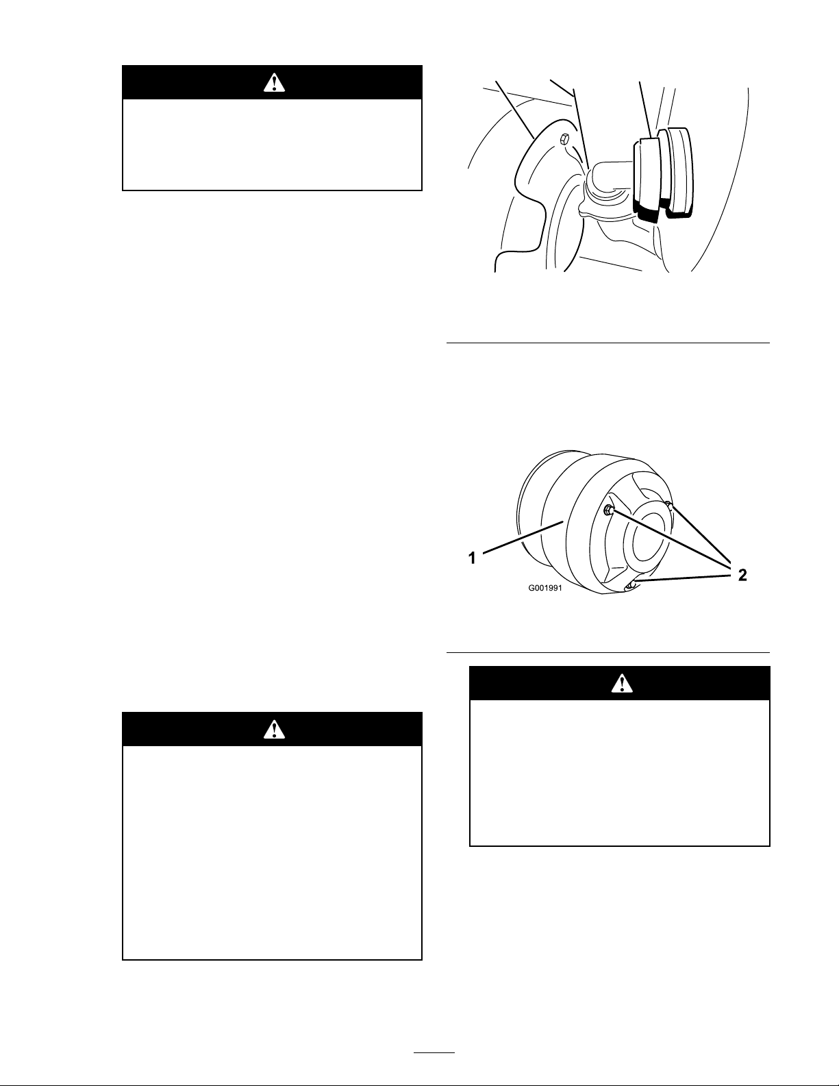
Charging the batter y pr oduces gasses
G001990
132
that can explode.
Nev er smok e near the batter y and k eep
spar ks and flames a w ay fr om batter y .
4. Install the batter y in the c hassis; refer to
Installing the Batter y .
Storing the Battery
If the mac hine will be stored for more than
30 da ys , remo v e the batter y and c harg e it fully .
Either store it on the shelf or on the mac hine .
Lea v e the cables disconnected if it is stored on the
mac hine . Store the batter y in a cool atmosphere
to a v oid quic k deterioration of the c harg e in the
batter y . T o prev ent the batter y from freezing,
mak e sure it is fully c harg ed.
Drive System
Maintenance
Figure 57
1. Clutch cover 3. Heat shield
2. Hose
4. R emo v e the 3 bolts securing the co v er to the
clutc h and remo v e the co v er ( Figure 58 ).
Note: Y ou ma y need to push the heat shield
( Figure 57 ) bac k as y ou remo v e the co v er .
Maintaining the Primary
Drive Clutch
After ev er y 400 operating hours or yearly , clean
and lubricate the clutc h as follo ws:
1. Stop the engine , remo v e the k ey , and set the
parking brak e .
2. Raise the front end of the spra yer and suppor t
it on jac k stands .
A spray er on a jack may be unsta ble
and slip of f of the jack, injuring an y one
beneath it.
• Do not star t the engine while the
spray er is on a jack.
• Al w ays r emo v e the k ey fr om the
ignition bef or e getting of f of the
spray er .
• Block the tir es when the spray er is on
a jack.
Figure 58
1. Cover
2. Bolts
T he dust in the clutch will become
airbor ne and could dama ge y our ey es or
y ou could inhale it causing br eathing
dif ficulties.
W ear safety go g g les and a dust mask
or other ey e and r espirator y pr otection
when perf or ming this pr ocedur e.
5. Lubricate the mo ving par ts in the areas circled
in Figure 59 using T oro Dr y Lubricant Spra y ,
a v ailable through y our A uthorized T oro Dealer
or Distributor .
3. Disconnect the hose located on the lo w er -front
face of the tank ( Figure 57 ).
51
Page 52
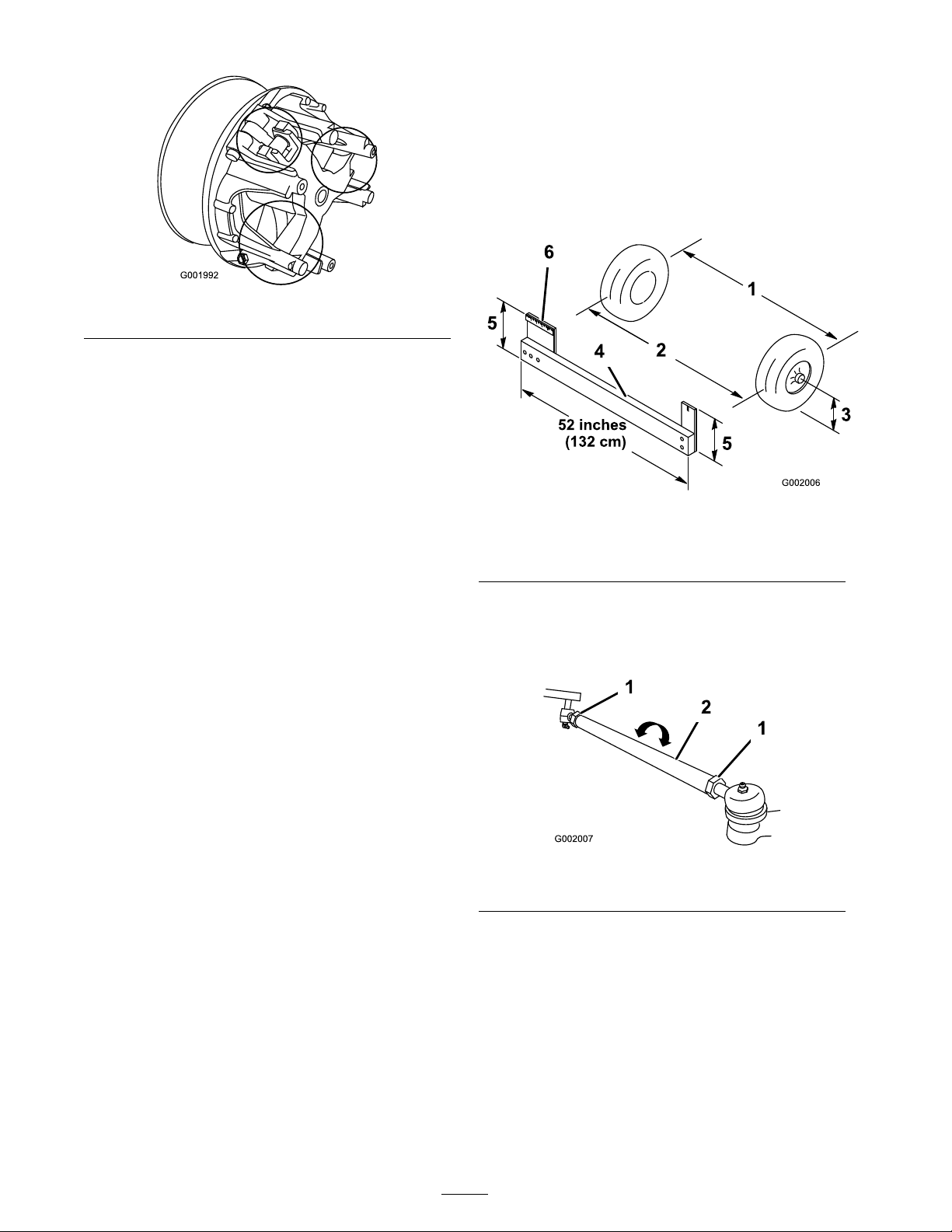
Figure 59
6. Install the clutc h co v er and secure it with the 3
bolts remo v ed previously .
7. Connect the hose on the front of the tank
( Figure 57 ).
Inspecting the Wheels/Tires
Chec k the wheels to ensure that they are mounted
securely after the first 8 operating hours and then
ev er y 100 hours thereafter . T or que the front bolts
to 50-55 ft-lb (68-74 N ⋅ m) and the rear lug n uts to
40-60 ft-lb (54-81 N ⋅ m).
Chec k the tire condition at least ev er y 100 hours
of operation. Operating accidents , suc h as hitting
curbs , can damag e a tire or rim and also disr upt
wheel alignment, so inspect tire condition after an
accident.
measurement of the front tires at axle height.
Use the same fixture or alignment g aug e to
accurately measure the front of the front tires
at axle height ( Figure 60 ).
T he front of the tires should be 0 to 1/4 inc h
(0 to 6 mm) closer than the bac k side of the
front tires .
Figure 60
1. Tire center line-back
2. Tire center line-front 5. Axle center line distance
3. Axle center line
4. Fixture
6. 6 inches (15 cm) ruler
5. If the measurement does not fall within the
specified rang e , loosen the jam n uts at both
ends of the tie rods ( Figure 61 ).
Adjusting the Front Wheel
Toe-In
Chec k the front wheel toe-in after ev er y
100 operating hours , or ann ually , whic hev er occurs
first. T he toe-in should be 0 to 1/4 inc h (0 to
6 mm).
1. Fill the tank with appro ximately 80 US g allons
(303 L) of w ater .
2. Chec k and fill all tires; refer to Chec king Tire
Pressure .
3. Dri v e the spra yer bac k and for th a few times
to relax the A-ar ms , then dri v e it forw ard at
least 10 ft (3 m).
4. Measure the distance betw een both of the
front tires at the axle height at both the front
and rear of the front tires ( Figure 60 ). A fixture
or alignment g aug e is needed for the rear
Figure 61
1. Jam nut
2. Tie rod
6. R otate both tie rods to mo v e the front of the
tire inw ard or outw ard.
Note: T he tie rods should be the same length
when y ou are finished.
7. Tighten the tie rod jam n uts when the
adjustment is cor rect.
8. Ensure that there is full tra v el of the steering
wheel in both directions .
52
Page 53
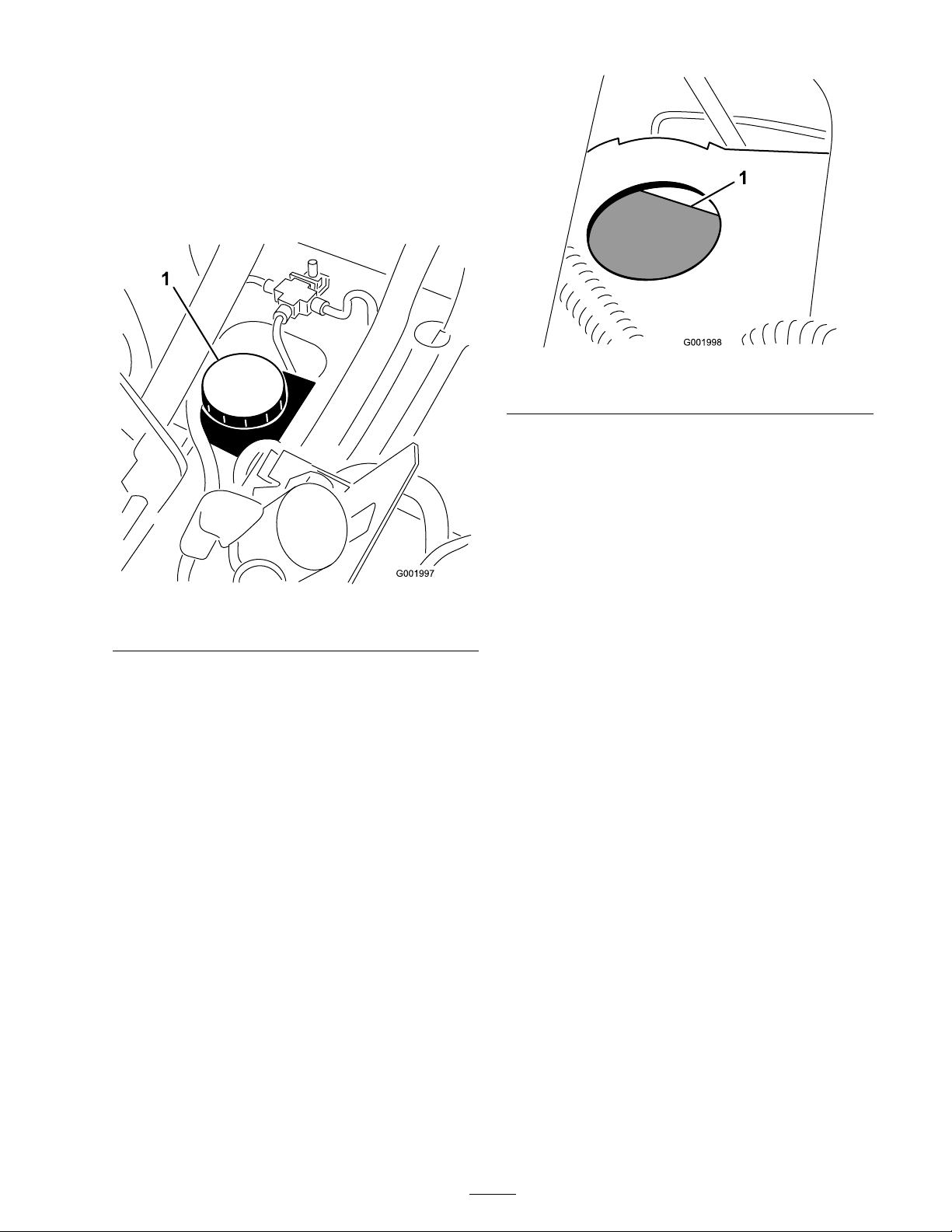
Brake Maintenance
Checking the Brake Fluid
T he brak e fluid reser v oir is shipped from the
factor y filled with DOT 3 brak e fluid. Chec k the
lev el before star ting the engine eac h da y .
Figure 63
1. Full line
3. If the fluid lev el is lo w , clean the area around
the reser v oir cap , remo v e the cap , and fill the
reser v oir to the proper lev el. Do not o v erfill.
Inspecting the Brakes
Figure 62
1. Brake uid reservoir
1. P osition the spra yer on a lev el surface , set the
parking brak e , stop the pump , stop the engine ,
and remo v e the ignition k ey .
2. T he fluid lev el should be up to the Full line on
the reser v oir ( Figure 63 ).
T he brak es are a critical safety component of the
spra yer . Inspect them as follo ws ev er y 100 hours:
• Inspect the brak e shoes for w ear or damag e .
If the lining (brak e pad) thic kness is less than
1/16 inc h (1.6 mm), re place the brak e shoes .
• Inspect the bac king plate and other
components for signs of ex cessi v e w ear or
defor mation. If any defor mation is found,
re place the appropriate components .
Adjusting the Parking Brake
Chec k the parking brak e adjustment ev er y 200
hours .
1. Loosen the set screw securing the knob to the
parking brak e lev er ( Figure 64 ).
53
Page 54
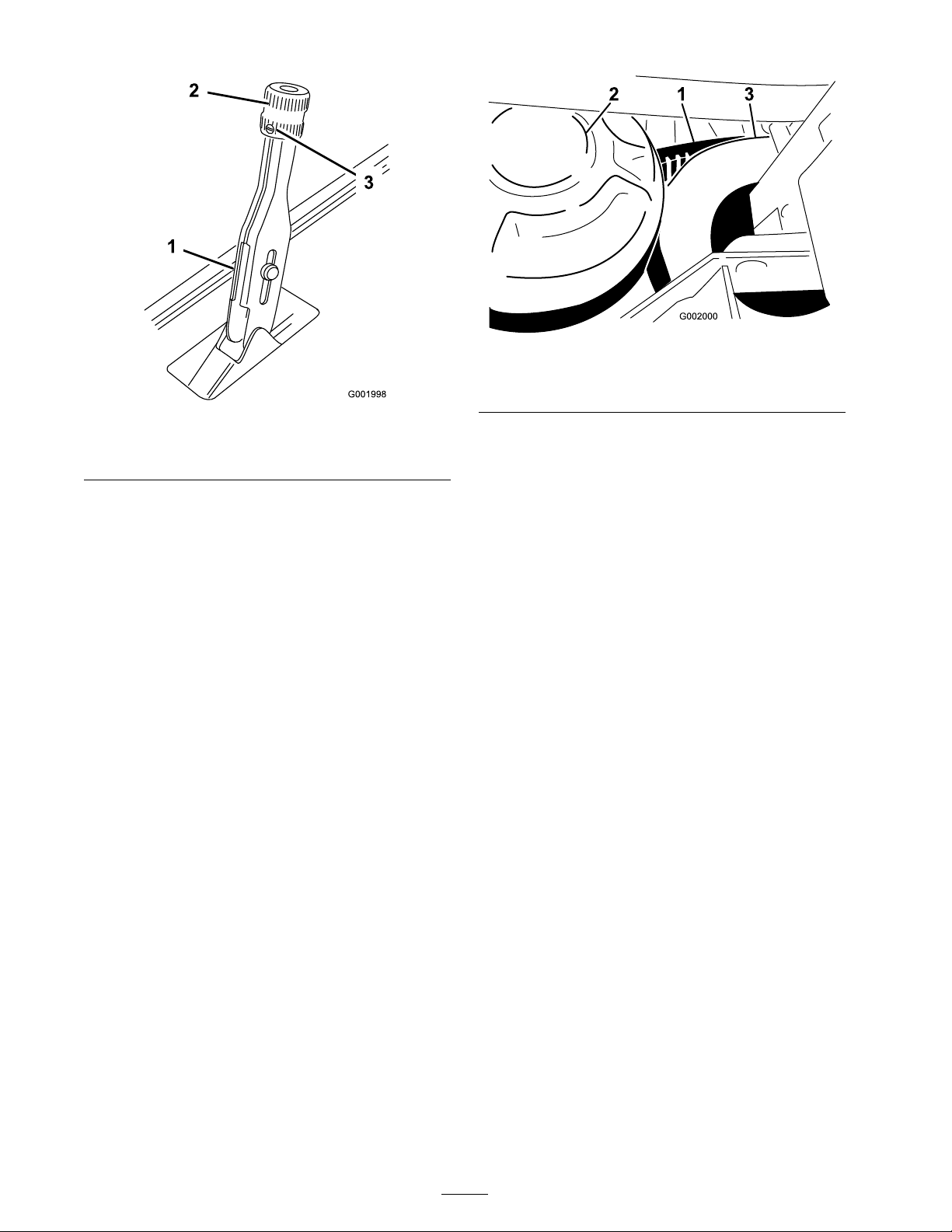
Figure 64
1. Parking brake lever
2. Knob
3. Set screw
2. R otate the knob until a force of 35-45 lb is
required to actuate lev er .
3. Tighten the set screw .
Belt Maintenance
Servicing the Drive Belt
Figure 65
1. Drive belt 3. Secondary clutch
2. Primary clutch
Replacing the Drive Belt
1. R otate and route the belt o v er the secondar y
clutc h ( Figure 65 ).
2. R emo v e the belt from the primar y clutc h.
3. Place the new belt o v er the primar y clutc h.
4. R otate and install it o v er the secondar y clutc h.
Adjusting the Steering
Pump Belt
Checking the Drive Belt
Chec k the condition of the dri v e belt after the first
da y of operation and ev er y 200 operating hours
thereafter .
1. P osition the spra yer on a lev el surface , set
the parking brak e , mo v e the rang e selector to
the Neutral position, stop the pump , stop the
engine , and remo v e the ignition k ey .
2. R otate and inspect the dri v e belt for ex cessi v e
w ear or damag e . R e place the belt if necessar y .
Chec k the tension of the steering pump belt after
the first da y of operation and ev er y 100 operating
hours thereafter . T he belt should flex 1/4 inc h (5
mm) when 5 lb of force (22 N) is applied midw a y
on the top span.
1. P ark the mac hine on a lev el surface , set the
parking brak e , tur n the ignition off , and
remo v e the k ey .
2. Loosen the steering pump mounting bolts
( Figure 66 ).
54
Page 55
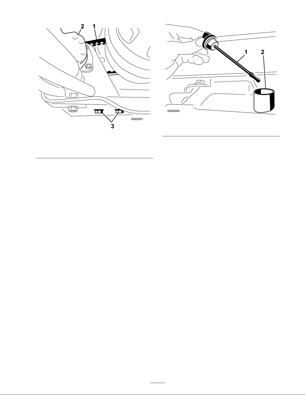
Figure 66
1. Steering pump belt
2. Steering pump
3. Mo v e the pump until the belt flex es 1/4 inc h (5
mm) with 5 lb . of force (22 N) then tighten the
mounting bolts , star ting with the bolt closest
to the engine crankshaft.
3. Steering pump mounting
bolts
Hydraulic System
Maintenance
Figure 67
1. Dipstick 2. Fill hole
Important: Be v er y car eful not to get
dir t or other contaminants into the opening
when checking the transmission oil.
3. Inser t the dipstic k into the tube and mak e
sure it is seated fully . R emo v e the dipstic k and
c hec k the oil lev el.
4. T he transaxle fluid lev el should be at the top of
the flat por tion of the dipstic k. If it is not, fill
the reser v oir with the appropriate fluid; refer
to Changing the T ransaxle/Hy draulic Fluid.
5. Install the dipstic k fir mly in place .
Checking the
Transaxle/Hydraulic Fluid
1. P osition the spra yer on a lev el surface , set the
parking brak e , stop the pump , stop the engine ,
and remo v e the ignition k ey .
2. R emo v e the transaxle dipstic k and wipe it with
a clean rag ( Figure 67 ).
Changing
Transaxle/Hydraulic
Fluid
Chang e transaxle/h y draulic fluid, filter and clean
strainer ev er y 800 hours .
1. P osition the spra yer on a lev el surface , set the
parking brak e , stop the pump , stop the engine ,
and remo v e the ignition k ey .
2. Place a drain pan under the drain plug of the
reser v oir .
3. R emo v e the drain plug from the side of the
reser v oir and let the h y draulic fluid flo w into
the drain pan ( Figure 68 ).
55
Page 56
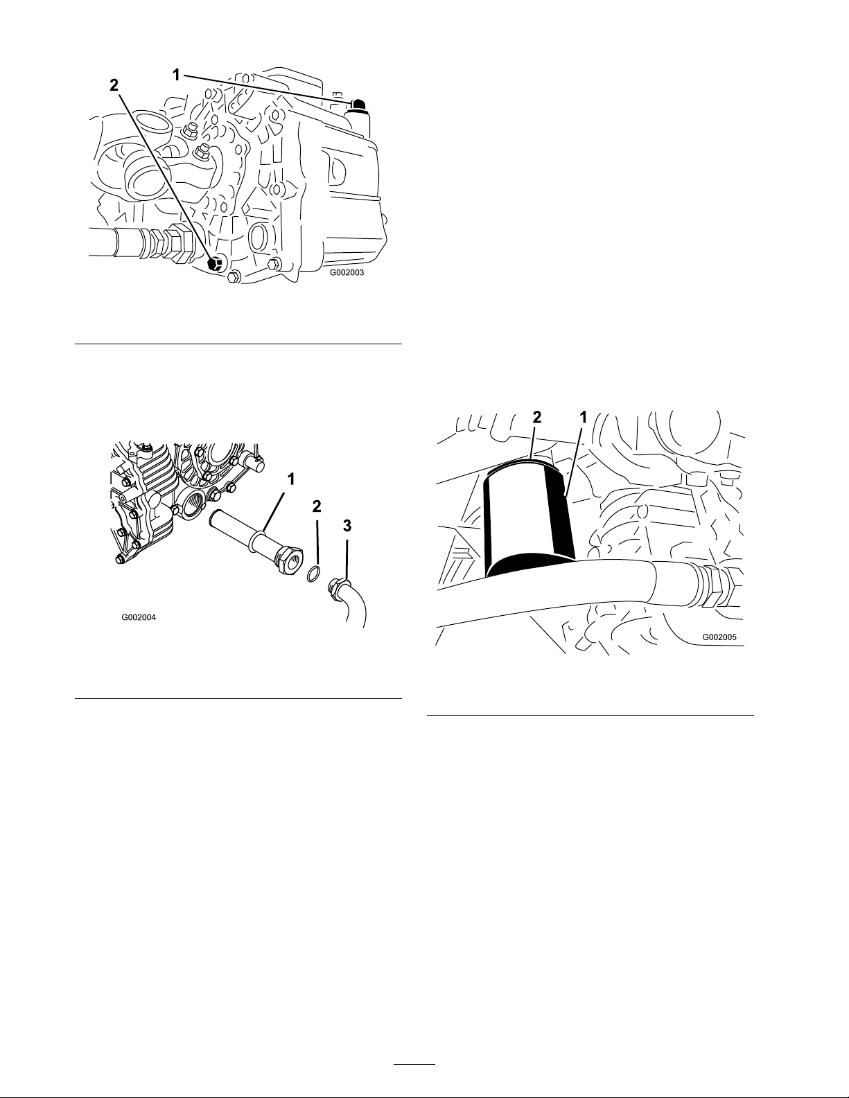
Figure 68
1. Hydraulic dipstick 2. Drain plug
Replacing the Hydraulic
Filter
Initially , re place the h y draulic filter after 8 operating
hours , thereafter , re place filter ev er y 800 hours .
Use the T oro re placement filter (P ar t No .
54-0110).
Important: Use of an y other filter may v oid
the w ar ranty on some components.
1. P osition the spra yer on a lev el surface , set the
parking brak e , stop the pump , stop the engine ,
and remo v e the ignition k ey .
2. Clean the area around the filter mounting area.
4. Note the orientation of the h y draulic hose and
90° fitting connected to the strainer .
5. R emo v e the h y draulic hose and 90° fitting
( Figure 69 ).
Figure 69
1. Hydraulic strainer
2. O-ring
3. 90° tting
6. R emo v e the strainer and clean it b y bac k
flushing it with a clean deg reaser .
7. Allo w the strainer to air dr y .
8. Install the strainer when the oil is draining .
9. Install the h y draulic hose and 90° fitting to the
strainer .
10. Install and tighten the drain plug .
11. Fill the reser v oir with appro ximately 7.5 qt. of
Dexron IIl A TF .
Important: Use onl y the h y draulic fluids
specified. Other fluids could cause system
dama ge.
12. Star t the engine and dri v e the spra yer to fill
the h y draulic system. R ec hec k the oil lev el and
re plenish it, if required.
3. Place a drain pan under the filter .
4. R emo v e the filter ( Figure 70 ).
Figure 70
1. Hydraulic lter 2. Gasket
5. Lubricate the new filter g ask et.
6. Ensure that the filter mounting area is clean.
7. Screw the filter on until the g ask et contacts the
mounting plate , then tighten the filter one-half
tur n.
8. Star t the engine and let it r un for about tw o
min utes to purg e air from the system. Stop the
engine and c hec k the h y draulic oil lev el and for
leaks .
56
Page 57
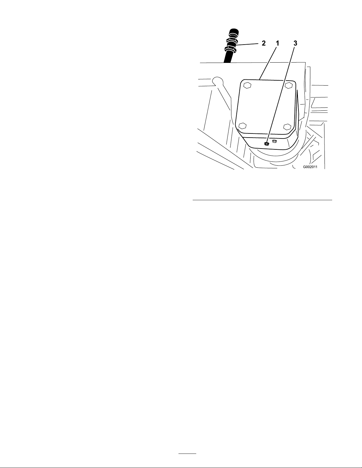
Spray System
Maintenance
Inspecting the Hoses
Ev er y 200 hours , examine eac h hose in the spra y
system for crac ks , leaks or other damag e . At the
same time , inspect the connections and fittings for
similar damag e . R e place any hoses and fittings if
damag ed.
Pump Maintenance
Inspecting the Pump
Ev er y 400 hours and/or yearly , ha v e an A uthorized
T oro Ser vice Distributor c hec k follo wing inter nal
pump components for damag e:
• Pump diaphragm
• Pressure dampener bladder
• Pump c hec k v alv es assemblies
R e place any components if necessar y .
Changing the Pump Drive Gearbox
Fluid
Chang e the pump dri v e g earbo x ev er y 400 hours .
1. P osition the spra yer on a lev el surface , set the
parking brak e , stop the pump , stop the engine ,
and remo v e the ignition k ey .
2. Place a pan under the drain plug on the pump
dri v e g ear bo x ( Figure 71 ).
Figure 71
1. Pump drive gearbox 3. Drain plug
2. Fill tube
3. R emo v e the fill plug and drain plug ( Figure 71 ),
allo wing the oil to drain into the pan.
4. Install and tighten the drain plug when the
fluid stops draining .
5. Add appro ximately 1 quar t (1 L) of Mobil SHC
634 Synthetic Lubricant to the fill tube .
Important: Use onl y Mobil SHC 634
Synthetic Lubricant or equi v alent synthetic
fluid in the gear bo x. Non-synthetic oils
may br eak do wn causing dama ge to the
pump gearbo x.
6. Install the fill plug .
Adjusting the Boom
Actuator
Inspect the actuator h y draulic oil for air bubbles
ev er y 400 hours .
1. P osition the spra yer on a lev el surface , lo w er
the booms into the spra y position.
2. Set the parking brak e , stop the pump , stop the
engine , and remo v e the ignition k ey
3. Attempt to lift the boom b y applying a
moderate amount of pressure (just enough
to lift the boom man ually) while obser ving
57
Page 58
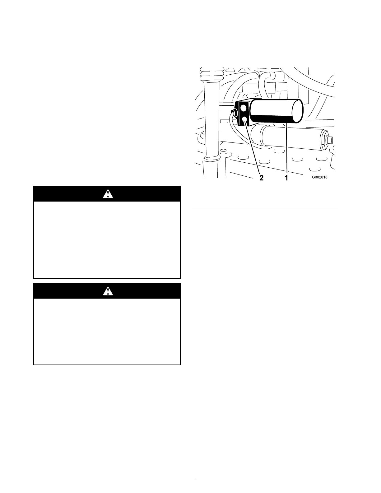
the actuator rod. If the actuator rod exhibits
mo v ement refer to belo w .
4. R e peat the procedure for the opposing boom.
If the actuator rod exhibits an axial mo v ement
(tra v els into or out of the cylinder) g reater than
0.085-0.100 inc h (2.16-2.54 mm), y ou ma y wish to
bleed the air from the h y draulic oil.
R efer to the Ser vice Manual for instr uctions on
ho w to bleed air from the actuators or contact an
A uthorized T oro Ser vice Distributor .
Emergency Manual
Operation of the Boom
Actuators
Note: Deter mine the left and right sides of the
mac hine from the nor mal operating position.
Use of the man ual r elief v alv e may cause the
boom to mo v e suddenl y and cause injur y to
y ou or other s.
• T ak e caution and adjust the man ual r elief
v alv e slo wl y .
• Ensur e the sur r ounding ar ea is clear and
no one is inside the operating range of
the boom.
1. Locate the man ual relief v alv e on the actuator
for eac h boom. T he man ual relief v alv e is the
smaller v alv e and is only on one side of the
actuator body ( Figure 72 ).
Figure 72
1. Actuator, right boom 2. Manual relief valve
Note: Due to the opposing orientation of
actuators in respect to eac h other the man ual
relief v alv e is on the forw ard face of the left
boom actuator and the rear face of the right
boom actuator .
2. Use a hexag onal wrenc h to loosen the man ual
relief v alv e no mor e than 2-3 tur ns . T he
cylinder should star t stroking man ually or b y
exter nal pressure at this time .
Adjusting the man ual r elief v alv e with
electrical po w er pr esent could cause the
actuator operate ir r egular l y and cause injur y
to y ou or other s.
Do not use the man ual r elief v alv e while
electrical po w er is being supplied to the
actuator .
In case of an emerg ency suc h that the boom
m ust be mo v ed and no 12V DC po w er source is
a v ailable , the man ual relief v alv e can be used to
reliev e pressure within the actuator and allo w the
booms to be mo v ed man ually .
Important: T he man ual v alv e must not be
loosened mor e than 4 tur ns. T ur ning the v alv e
mor e than 4 tur ns may cause the v alv e to come
of f completel y allo wing h y draulic oil to spill
out.
3. Once the original position of the actuator
is reco v ered, close the man ual relief v alv e .
T or que the v alv e to 1.1-2.1 ft-lb (1.5-2.9 N ⋅ m).
Inspecting the Nylon Pivot
Bushings
Inspect the nylon pi v ot bushings in the center
boom ev er y 400 hours and/or yearly for damag e .
1. P osition the spra yer on a lev el surface , set the
parking brak e , stop the pump , stop the engine ,
and remo v e the ignition k ey .
2. Extend the booms to the spra y position and
suppor t the booms using stands or straps from
a lift.
3. With the w eight of the boom suppor ted,
remo v e the bolt and n ut securing the pi v ot pin
to the boom assembly ( Figure 73 ). R emo v e the
pi v ot pin.
58
Page 59
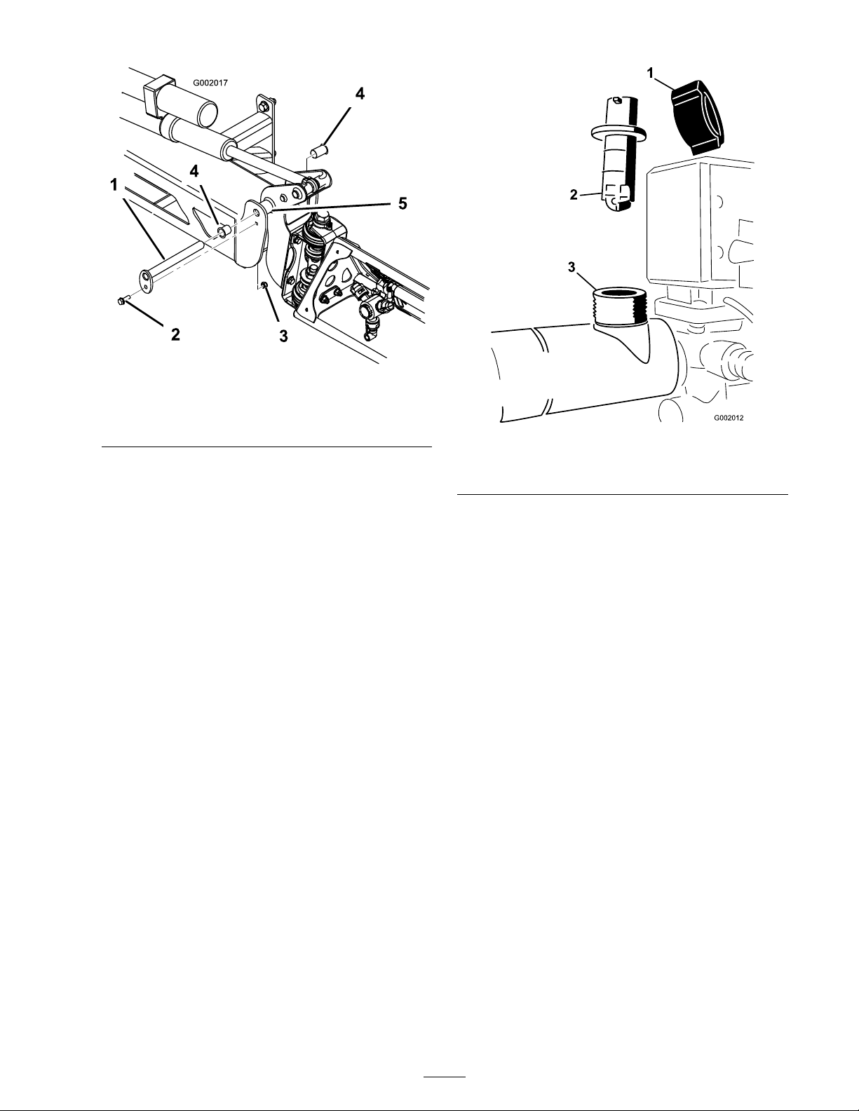
Figure 73
1. Pivot pin
2. Bolt 5. Pivot bracket
3. Nut
4. Nylon bushing
4. R emo v e the boom and pi v ot brac k et assembly
from the center frame to access the nylon
bushings .
5. R emo v e and inspect the nylon bushings from
the front and bac k sides of the pi v ot brac k et
( Figure 73 ). R e place any damag ed bushings .
6. Place a small amount of oil on the nylon
bushings and install them into pi v ot brac k et.
7. Install the boom and pi v ot brac k et assembly
into the center frame , aligning the openings
( Figure 73 ).
8. Install the pi v ot pin and secure it with the bolt
and n ut remo v ed previously .
R e peat the procedure for eac h boom.
Cleaning
Cleaning the Flowmeter
Occasionally , the flo wmeter ma y need to be
cleaned to remo v e an obstr uction.
Figure 74
1. Retaining cap
2. Paddle wheel assembly
3. Flowmeter body
3. Carefully pull the paddle wheel assembly from
the body .
4. Use w ar m w ater , a soft-bristled br ush, and
a mild deterg ent as necessar y to clean the
flo wmeter body and paddle wheel. R emo v e
any small metallic debris .
Important: Do not use solv ents or fuel
to clean the flo wmeter .
5. Install the paddle wheel assembly into the
flo wmeter body .
Important: T he paddle wheel assembl y
will onl y fit into the body one w ay , in a
detent slot on the side of the body . Do not
f orce the paddle wheel assembl y into the
body in an y other orientation.
6. Install the retaining cap .
7. Connect the wire to the flo wmeter .
Cleaning the Suction
Note: Mak e sure the pump is off when
perfor ming this procedure .
1. Disconnect the flo wmeter wire from wiring
har ness .
2. R emo v e the retaining cap from the flo wmeter
body ( Figure 74 ).
Strainer
Clean the suction strainer daily . If y ou are using
w etable po w ders , clean it after ev er y tank.
1. R emo v e the retainer from the red fitting
attac hed to the larg e hose on the top of the
tank.
59
Page 60
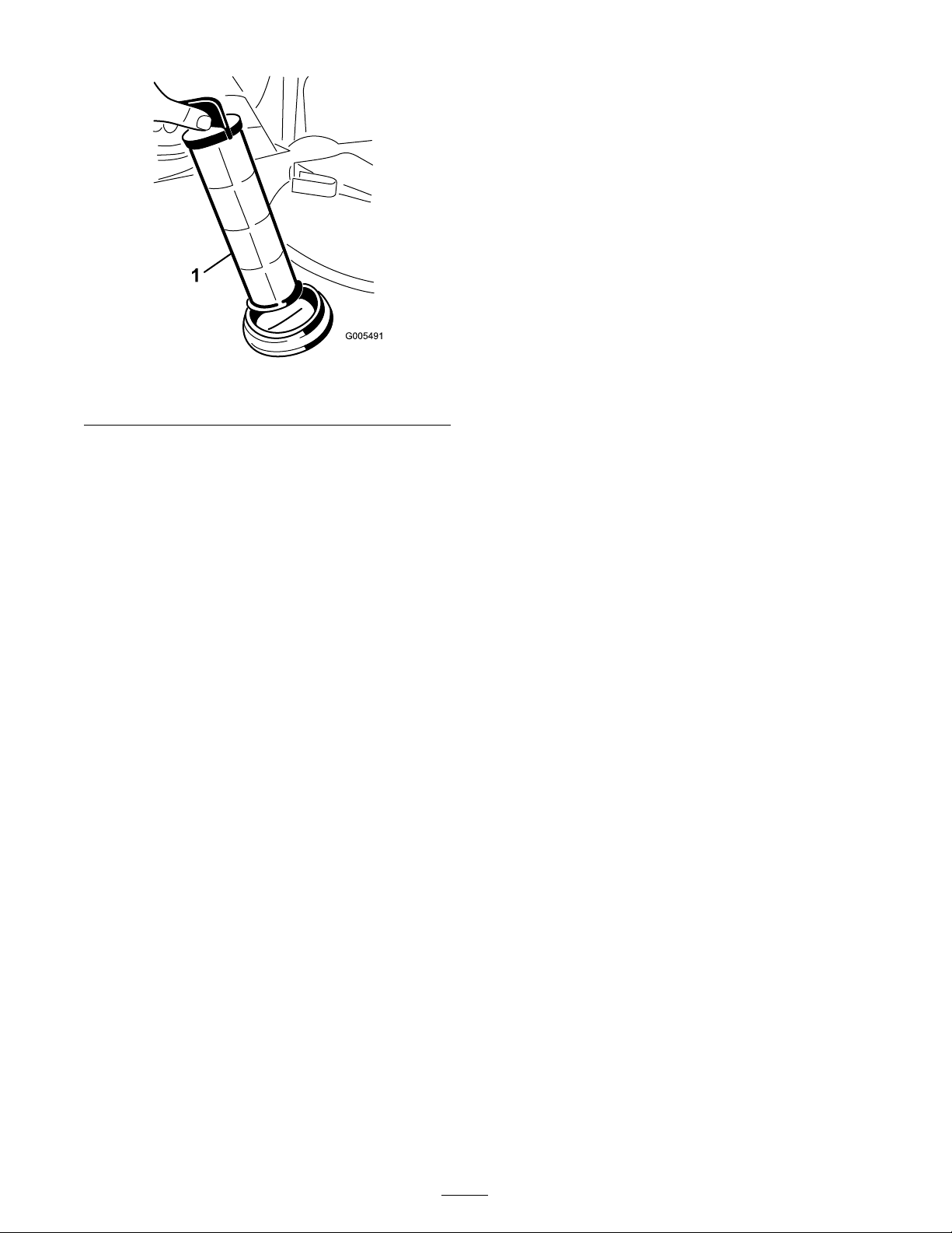
Figure 75
1. Suction strainer
2. Disconnect the hose from the tank.
3. Pull the strainer out of the hole .
4. Clean the strainer with clean r unning w ater .
5. R e place the strainer , seating it fully into the
hole .
6. Connect the hose to the top of the tank and
secure it with the retainer .
60
Page 61

Storage
1. P osition the spra yer on a lev el surface , set the
parking brak e , stop the pump , stop the engine ,
and remo v e the ignition k ey .
2. Clean dir t and g rime from the entire mac hine ,
including the outside of the engine’ s cylinder
head fins and blo w er housing .
Important: Y ou can w ash the machine
with mild detergent and w ater . Do not use
high pr essur e w ater to w ash the machine.
Pr essur e w ashing may dama ge the
electrical system or w ash a w ay necessar y
g r ease at friction points. A v oid ex cessi v e
use of w ater , especiall y near the contr ol
panel, lights, engine, and the batter y .
3. Clean the spra y system; refer to Cleaning ,
pag e 59 .
4. Add a r ust inhibiting, non-alcohol based, R V
antifreeze solution to the system and r un the
pump for a few min utes to circulate it through
the system, then drain the spra y system as
completely as possible .
5. Use the boom lift switc hes to raise the booms .
Raise the booms until they ha v e mo v ed
completely into boom transpor t cradle for ming
the “X” transpor t position and the boom
cylinders are fully retracted. Mak e sure the
boom cylinders are fully retracted to prev ent
actuator rod damag e .
6. Inspect the brak es; refer to Inspecting the
Brak es in Brak e Maintenance , pag e 53 .
7. Ser vice the air cleaner; refer to Ser vicing the
Air Cleaner in Engine Maintenance , pag e 45 .
8. Grease the spra yer; refer to Lubrication ,
pag e 42 .
9. Chang e the crankcase oil; refer to Ser vicing
Engine Oil in Engine Maintenance , pag e 45 .
10. Chec k the tire pressure; refer to Chec king the
Tire Pressure in Dri v e System Maintenance ,
pag e 51 .
11. F or storag e o v er 30 da ys , pre pare the fuel
system as follo ws:
A. Add a petroleum based
stabilizer/conditioner to fuel in the
tank.
F ollo w mixing instr uctions from stabilizer
man ufacturer . (1 oz. per g allon). Do not
use an alcohol based stabilizer (ethanol or
methanol).
Note: A fuel stabilizer/conditioner is
most effecti v e when mix ed with fresh
g asoline and used at all times .
B . R un the engine to distribute conditioned
fuel through the fuel system (5 min utes).
C . Stop the engine , allo w it to cool, and drain
the fuel tank.
D . R estar t the engine and r un it until it stops .
E. Chok e the engine .
F . Star t and r un the engine until it will not
star t ag ain.
G . Dispose of fuel properly . R ecycle as per
local codes .
Important: Do not stor e
sta biliz er/conditioned gasoline
o v er 90 days
12. R emo v e the spark plugs and c hec k their
condition; refer to Changing Spark Plugs in
Engine Maintenance , pag e 45 .
13. With the spark plugs remo v ed from the engine ,
pour tw o tablespoons of engine oil into the
spark plug hole .
14. Use the electric star ter to crank the engine and
distribute the oil inside the cylinder .
15. Install the spark plugs and tighten to
recommended tor que; refer to Changing Spark
Plugs in Engine Maintenance , pag e 45 .
Note: Do not install the wire on the spark
plug(s).
16. R emo v e the batter y from the c hassis ,
c hec k the electrolyte lev el, and c harg e
it fully; refer to Ser vicing the Batter y in
Electrical System Maintenance , pag e 49 .
Note: Do not connect the batter y cables to
the batter y posts during storag e .
Important: T he batter y must be full y
charged to pr ev ent it fr om fr eezing and
being dama ged at temperatur es belo w 32°F
(0°C). A full y charged batter y maintains its
charge f or a bout 50 days at temperatur es
lo w er than 40°F (4°C). If the temperatur es
will be a bo v e 40°F (4°C), check the w ater
lev el in the batter y and charge it ev er y 30
days.
61
Page 62

17. Chec k and tighten all bolts , n uts , and screws .
R e pair or re place any par t that is damag ed.
18. Chec k the condition of all spra y hoses ,
re placing any that are damag ed or w or n.
19. Tighten all hose fittings .
20. P aint all scratc hed or bare metal surfaces .
P aint is a v ailable from y our A uthorized Ser vice
Dealer .
21. Store the mac hine in a clean, dr y g arag e or
storag e area.
22. R emo v e the ignition k ey and put it in a safe
place out of the reac h of c hildren.
23. Co v er the mac hine to protect it and k ee p it
clean.
62
Page 63

Troubleshooting
Troubleshooting the Engine and Vehicle
Problem
The starter does not crank.
The engine cranks, but will
not start.
Possible Cause Corrective Action
1. The range selector is in a
gear other than Neutral.
2. The electrical
connections are
corroded or loose.
3. A fuse is blown or loose. 3. Correct or replace fuse.
4. The battery is
discharged.
5. The safety
interlock system is
malfunctioning.
6. A broken starter or starter
solenoid.
7. Seized internal engine
components.
1. The fuel tank is empty. 1. Fill with fresh fuel.
2. Dirt, water, or stale fuel
is in the fuel system.
3. Clogged fuel line. 3. Clean or replace.
4. The spark plug lead is
disconnected.
5. A spark plug is damaged
or dirty.
6. The kill relay is not
energized.
7. The ignition is broken. 7. Contact your Authorized
1. Press the brake pedal and
move the range selector
to the Neutral position.
2. Check the electrical
connections for good
contact.
4. Charge or replace the
battery.
5. Contact your Authorized
Service Dealer.
6. Contact your Authorized
Service Dealer.
7. Contact your Authorized
Service Dealer.
2. Drain and ush the fuel
system; add fresh fuel.
4. Reconnect the spark
plug.
5. Replace the spark plug.
6. Contact your Authorized
Service Dealer.
Service Dealer.
63
Page 64

Problem
Possible Cause Corrective Action
The engine starts, but does
not keep running.
The engine runs, but knocks
or misses.
1. The fuel tank vent is
1. Replace the fuel cap.
restricted.
2. Dirt or water in the fuel
system.
2. Drain and ush the fuel
system; add fresh fuel.
3. The fuel lter is clogged. 3. Replace the fuel lter.
4. A fuse is blown or loose. 4. Correct or replace fuse.
5. The fuel pump is broken. 5. Contact your Authorized
Service Dealer.
6. The carburetor is broken. 6. Contact your Authorized
Service Dealer.
7. Loose wires or poor
connections.
8. The cylinder head gasket
is broken.
1. Dirt, water, or stale fuel
is in the fuel system.
2. A spark plug lead is
loose.
7. Check and tighten wire
connections.
8. Contact your Authorized
Service Dealer.
1. Drain and ush the fuel
system; add fresh fuel.
2. Reconnect the spark
plug lead.
3. A spark plug is broken. 3. Replace the spark plug.
4. Loose wires or poor
connections.
4. Check and tighten wire
connections.
5. Engine overheating. 5. See Engine Overheats.
The engine will not idle.
1. The fuel tank vent is
1. Replace the fuel cap.
restricted.
2. Dirt, water, or stale fuel
is in the fuel system.
3. A spark plug is damaged
2. Drain and ush the fuel
system; add fresh fuel.
3. Replace the spark plug.
or broken.
4. Carburetor idle passages
are plugged.
5. The idle speed adjusting
screw is incorrectly set.
4. Contact your Authorized
Service Dealer.
5. Contact your Authorized
Service Dealer.
6. The fuel pump is broken. 6. Contact your Authorized
Service Dealer.
7. Low compression.
7. Contact your Authorized
Service Dealer.
8. The air cleaner element
8. Clean or replace.
is dirty.
64
Page 65

Problem
Possible Cause Corrective Action
The engine overheats.
The engine loses power.
1. The crankcase oil level is
incorrect.
1. Fill or drain to the full
mark.
2. Excessive loading. 2. Reduce load; use lower
ground speed.
3. The air intake screens are
3. Clean with every use.
dirty.
4. The cooling ns and
4. Clean with every use.
air passages under the
engine blower housing
and/or the rotating
air intake screen are
plugged.
5. The fuel mixture is lean. 5. Contact your Authorized
Service Dealer.
1. The crankcase oil level is
incorrect.
2. The air cleaner element
1. Fill or drain to the full
mark.
2. Clean or replace.
is dirty.
3. Dirt, water, or stale fuel
is in the fuel system.
4. The engine is
3. Drain and ush the fuel
system; add fresh fuel.
4. See Engine Overheats.
overheated.
5. A spark plug is damaged
5. Replace the spark plug.
or dirty.
6. The vent hole in the
6. Replace the fuel cap.
fuel tank vent tting is
plugged.
7. Low compression.
7. Contact your Authorized
Service Dealer.
Abnormal vibration or noise.
The machine will not
operate or is sluggish in
either direction because the
engine bogs down or stalls.
1. The engine mounting
bolts are loose.
2. There is a problem with
the engine.
1. Tighten the engine
mounting bolts.
2. Contact your Authorized
Service Dealer.
1. The parking brake is set. 1. Release the parking
brake.
65
Page 66

Problem
Possible Cause Corrective Action
The machine will not
operate in either direction.
Troubleshooting the Spray System
Problem
A boom section does not
spray.
1. The range selector is in
the Neutral position.
2. The parking brake was
not released or the
parking brake is not
releasing.
3. The transmission is
broken.
4. The control linkage
needs adjustment or
replacement.
5. The drive shaft or wheel
hub key has been
damaged.
Possible Cause Corrective Action
1. The electrical connection
on the boom valve is
dirty or disconnected.
1. Press the brake and shift
the range selector into a
gear.
2. Release the parking brake
or check the linkage.
3. Contact your Authorized
Service Dealer.
4. Contact your Authorized
Service Dealer.
5. Contact your Authorized
Service Dealer.
1. Turn the valve off
manually. Disconnect
the electrical connector
on the valve and clean all
leads, then reconnect it.
A boom section does not
turn off.
2. Blown fuse 2. Check the fuses and
replace them as
necessary.
3. Pinched hose 3. Repair or replace the
hose.
4. A boom by-pass valve is
improperly adjusted.
5. Damaged boom valve 5. Contact your Authorized
6. Damaged electrical
system
1. The valve is damaged. 1. Stop the spray system
4. Adjust the boom by-pass
valves.
Service Dealer.
6. Contact your Authorized
Service Dealer.
and pump and turn off
the sprayer. Remove
the retainer from under
the boom valve and pull
out the motor and stem.
Inspect all parts and
replace any that appear
damaged.
66
Page 67

Problem
A boom valve is leaking 1. An O-ring is deteriorated. 1. Stop the spray system
Possible Cause Corrective Action
and pump and turn off
the sprayer. Disassemble
the valve and replace the
O-rings.
A pressure drop occurs
when you turn on a boom.
Boom actuator is not
operating properly.
1. The boom bypass valve
is improperly adjusted.
2. There is an obstruction
in the boom valve body.
3. A nozzle lter is damaged
or clogged.
1. A thermal breaker in the
fuse block responsible for
powering the actuator
has tripped due to
overheating.
2. A thermal breaker in
the boom actuator
responsible for powering
the actuator has tripped
or malfunctioned.
1. Adjust the boom bypass
valve.
2. Remove the inlet and
outlet connections to the
boom valve and remove
any obstructions.
3. Remove and inspect all
nozzles.
1. Wait for the system
to cool down before
resuming operation.
If the thermal breaker
trip repeatedly, contact
your Authorized Service
Dealer.
2. Contact your Authorized
Service Dealer.
Troubleshooting the Spray Pro Monitor
Problem
The monitor does not
function.
The Speed is always 0 or
erratic.
1. The monitor cable is
2. The monitor or cable is
1. The monitor cable is
2. The speed sensor is not
3. The speed sensor is
Possible Cause Corrective Action
1. Connect the monitor
loose or disconnected.
2. Contact your Authorized
damaged.
1. Connect the monitor
loose.
2. Calibrate the speed
calibrated correctly.
3. Contact your Authorized
damaged.
cable.
Service Dealer.
cable.
sensor.
Service Dealer.
67
Page 68

Problem
Possible Cause Corrective Action
The Area is inaccurate.
The Distance is inaccurate.
The monitor does not
display Application Rate or
Total Volume.
1. The sprayer width is not
correctly entered.
2. The speed sensor is not
calibrated correctly.
3. The speed sensor is
damaged.
1. The speed sensor is not
calibrated correctly.
2. The speed sensor is
damaged.
1. The monitor cable is
loose.
2. The ow meter is dirty or
clogged.
3. The ow meter is not
calibrated correctly.
4. The ow meter is
damaged.
1. Check and set the
appropriate Width in
the calibration mode.
2. Calibrate the speed
sensor.
3. Contact your Authorized
Service Dealer.
1. Calibrate the speed
sensor.
2. Contact your Authorized
Service Dealer.
1. Connect the monitor
cable.
2. Clean the ow meter.
3. Calibrate the ow meter.
4. Contact your Authorized
Service Dealer.
The Total Volume is
inaccurate.
The monitor displays 6553.5
when in the Application Rate
setting.
The monitor is erratic in
operation.
The displayed
measurements do not
make sense.
The monitor reads “OFL.”
1. The ow meter is dirty or
clogged.
2. The ow meter is not
calibrated correctly.
3. The ow meter is
damaged.
1. The monitor is not
receiving data from the
speed sensor.
1. A two-way radio is too
close to the monitor or
its cables.
1. The Units of
Measurement is set
to a system other than
what you expect.
1. The data has exceeded
the maximum allowed.
1. Clean the ow meter.
2. Calibrate the ow meter.
3. Contact your Authorized
Service Dealer.
1. Contact your Authorized
Service Dealer.
1. Keep two-way radios
away from the monitor
and its cables.
1. Check the Units of
Measurement to ensure
that it is set correctly.
1. Press and hold the
[Reset] button to clear
the monitor.
68
Page 69
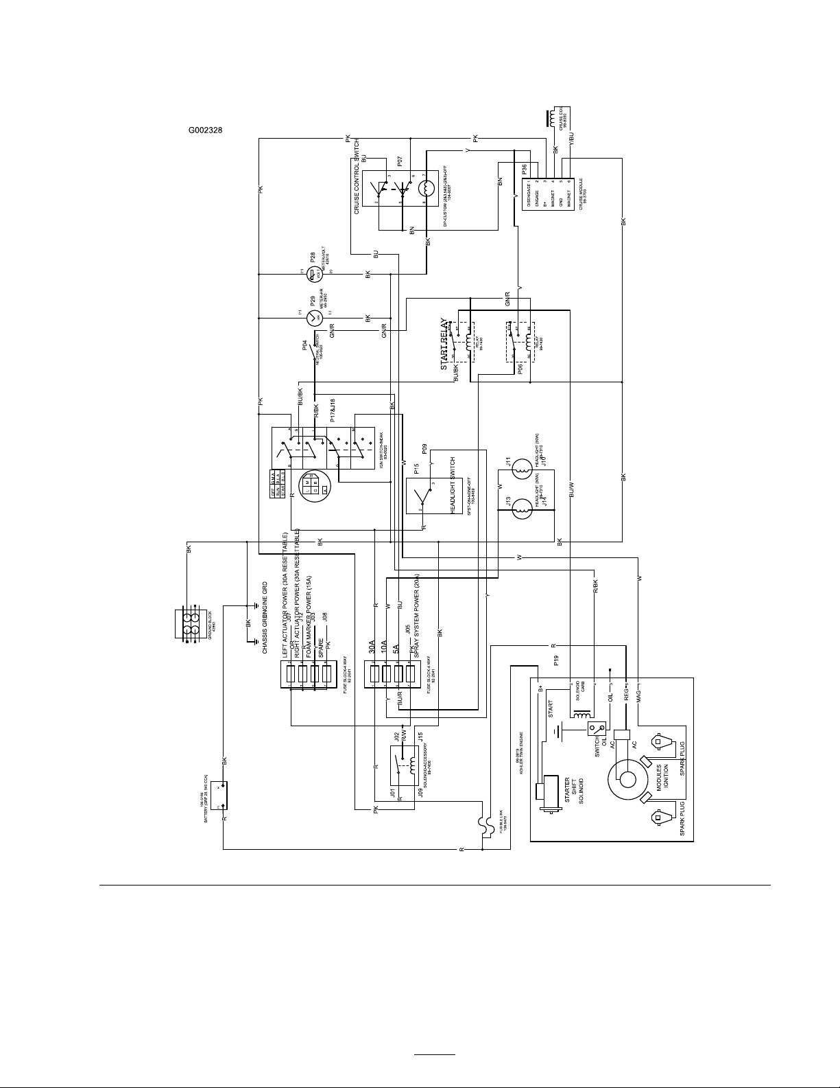
Schematics
Electrical, vehicle (Rev. B)
69
Page 70
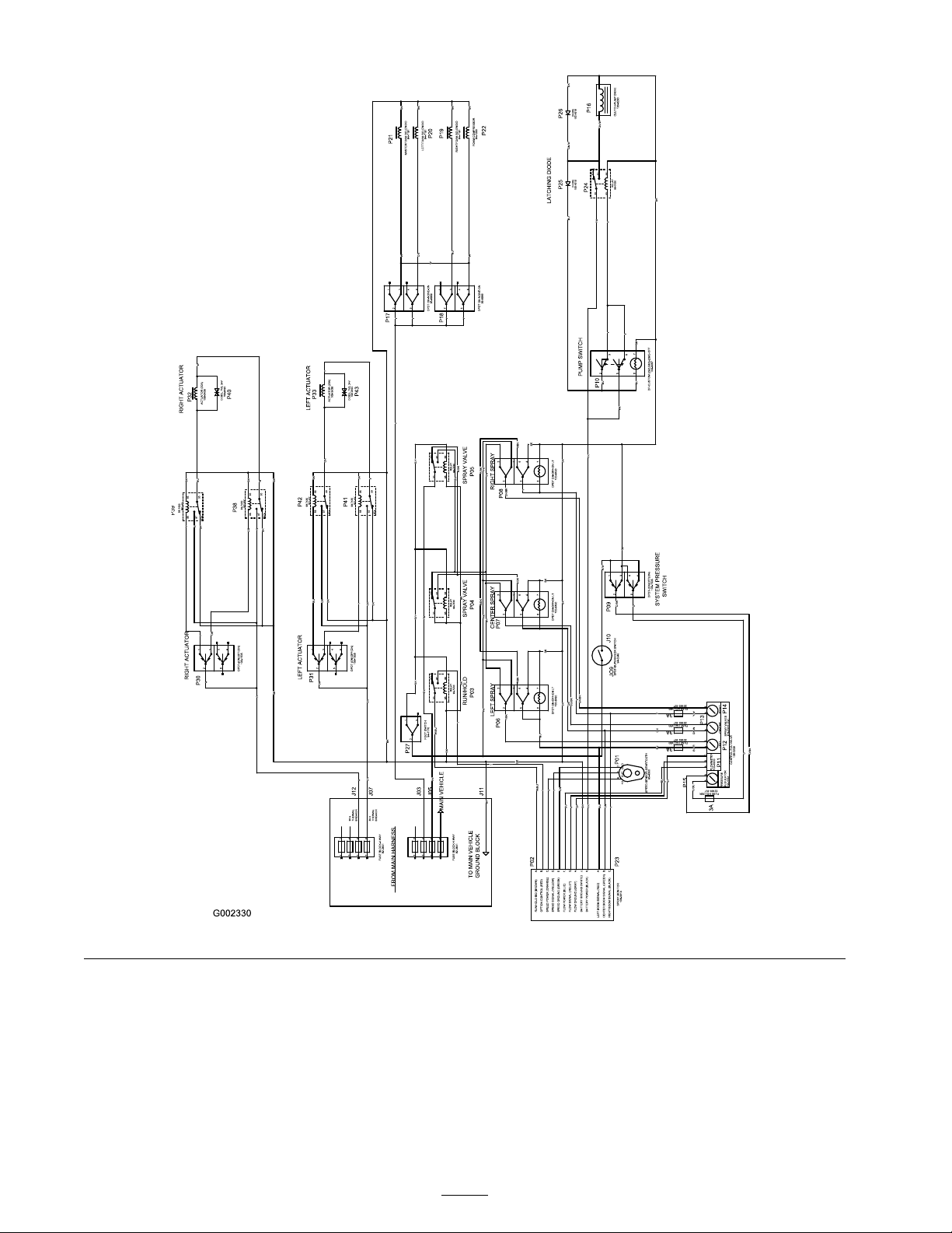
Electrical, spray system (Rev. A)
70
Page 71
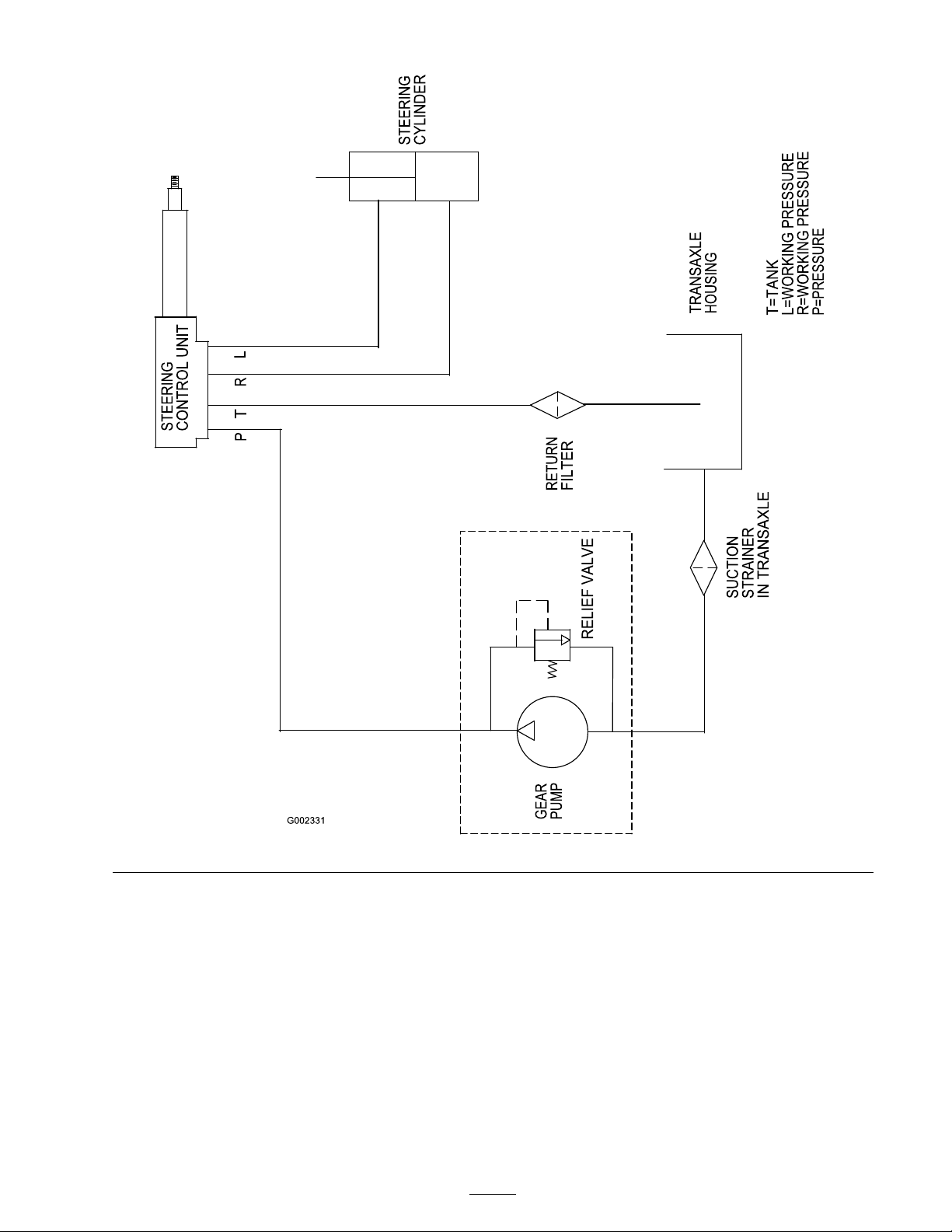
Hydraulic (Rev. A)
71
Page 72
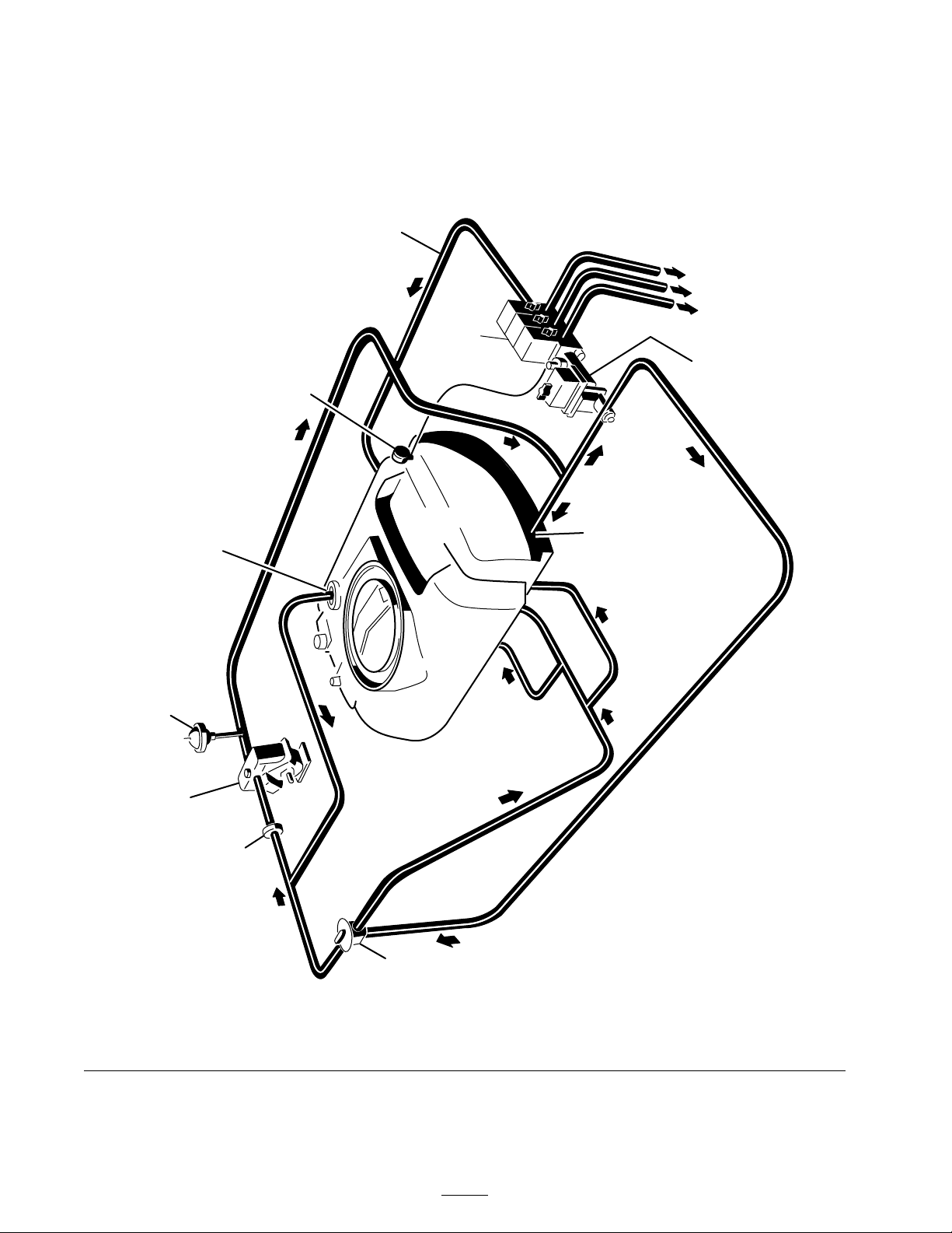
G005405
PRESSURE
PRESSURE
RELIEF
VALVE
PRESSURE
CONTROL
VALVE
LEFT BOOMSUPPLY
CENTERBOOMSUPPL
Y
RIGHT BOOMSUPPLY
BOOM
VALVES
BOOMBYPASS
PRESSURE
GAUGE
PRESSURE
TOP MOUNTED
SUCTIONFILTER
PRESSURE
DAMPENER
1203
DIAPHRAGM
PUMP
SUCTION
DAMPENER
SUCTION
SUCTION
AGIT
ATION
CONTROL
VALVE
SPRAY
TANK
AGITATION
MP 1250
FLOWDIAGRAM
Flow Diagram (Rev. A)
72
Page 73

Page 74

Page 75

Evaporative Emission Control Warranty Statement
California Evaporative Emission Control Warranty Statement
Your Warranty Rights and Obligations
Introduction
The California Air Resources Board and The Toro® Company are pleased to explain the evaporative emission control system’s warranty
on your 2007 model year equipment. In California, new equipment that use small off-road engines must be designed, built, and
equipped to meet the State’s stringent anti-smog standards. The Toro® Company must warrant the evaporative emission control
system on your equipment for two years provided there has been no abuse, neglect or improper maintenance of your equipment.
Your evaporative emission control system may include parts such as: fuel lines, fuel line ttings, and clamps.
Manufacturer’s Warranty Coverage:
This evaporative emission control system is warranted for two years. If any evaporative emission-related part on your equipment is
defective, the part will be repaired or replaced by The Toro® Company.
Owner’s Warranty Responsibilities:
• As the equipment owner, you are responsible for performance of the required maintenance listed in your Operator’s Manual.
The Toro® Company recommends that you retain all receipts covering maintenance on your equipment, but The Toro® Company
cannot deny warranty solely for the lack of receipts.
• As the equipment owner, you should however be aware that The Toro® Company may deny you warranty coverage if your emission
warranty parts have failed due to abuse, neglect, or improper maintenance or unapproved modications.
• You are responsible for presenting your equipment to an Authorized Service Dealer as soon as the problem exists. The warranty
repairs should be completed in a reasonable amount of time, not to exceed 30 days. If you have a question regarding your warranty
coverage, you should contact The Toro® Company at 1-952–948–4027 or call us toll free at the number listed in your Toro
Warranty statement.
Defects Warranty Requirements:
1. The warranty period begins on the date the engine or equipment is delivered to an ultimate purchaser.
2. General Evaporative Emissions Warranty Coverage. The emission warranty parts must be warranted to the ultimate purchaser and
any subsequent owner that the evaporative emission control system when installed was:
A. Designed, built, and equipped so as to conform with all applicable regulations; and
B. Free from defects in materials and workmanship that causes the failure of a warranted part for a period of two years.
3. The warranty on evaporative emissions-related parts will be interpreted as follows:
A. Any warranted part that is not scheduled for replacement as required maintenance in the written instructions must be
warranted for the warranty period of two years. If any such part fails during the period of warranty coverage, it must be
repaired or replaced by The Toro® Company. Any such part repaired or replaced under the warranty must be warranted for a
time not less than the remaining warranty period.
B. Any warranted part that is scheduled only for regular inspection in the written instructions must be warranted for the warranty
period of two years. A statement in such written instructions to the effect of “repair or replace as necessary” will not reduce
the period of warranty coverage. Any such part repaired or replaced under warranty must be warranted for a time not less
than the remaining warranty period.
C. Any warranted part that is scheduled for replacement as required maintenance in the written instructions must be warranted
for the period of time prior to the rst scheduled replacement point for that part. If the part fails prior to the rst scheduled
replacement, the part must be repaired or replaced by The Toro® Company. Any such part repaired or replaced under
warranty must be warranted for a time not less than the remainder of the period prior to the rst scheduled replacement point
for the part.
D. Repair or replacement of any warranted part under the warranty provisions of this article must be performed at no charge to
the owner at an Authorized Service Dealer.
E. Notwithstanding the provisions of subsection (D) above, warranty services or repairs must be provided at an Authorized
Service Dealer.
F. The owner must not be charged for diagnostic labor that leads to the determination that a warranted part is in fact defective,
provided that such diagnostic work is performed at an Authorized Service Dealer.
G. Throughout the evaporative emission control system’s two year warranty period, The Toro® Company must maintain a supply
of warranted parts sufcient to meet the expected demand for such parts.
H. Manufacturer approved replacement parts must be used in the performance of any warranty maintenance or repairs and must
be provided without charge to the owner. Such use will not reduce the warranty obligations of The Toro® Company.
I. The use of any add-on or modied parts will be grounds for disallowing a warranty claim made in accordance with this
article. The Toro® Company will not be liable under this Article to warrant failures of warranted parts caused by the use of an
add-on or modied part.
J. The Toro® Company shall provide any documents that describe the warranty procedures or policies within ve working
days of request by the Air Resources Board.
The following lists includes the parts covered under this warranty:
• Fuel Lines
• Fuel Line Fittings
• Clamps
Emission Warranty Parts List:
374-0092 Rev B
Page 76

The Toro General Commercial Products Warranty
A Two-Year Limited Warranty
Conditions and Products Covered
The Toro® Company and its afliate, Toro Warranty Company,
pursuant to an agreement between them, jointly warrant your
Toro Commercial Product (“Product") to be free from defects
in materials or workmanship for two years or 1500 operational
hours*, whichever occurs rst. Where a warrantable condition
exists, we will repair the Product at no cost to you including
diagnosis, labor, parts, and transportation. This warranty
begins on the date the Product is delivered to the original retail
purchaser.
P r o d u c t e q u i p p e d w i t h h o u r m e t e r
Instructions for Obtaining Warranty Service
You are responsible for notifying the Commercial Products
Distributor or Authorized Commercial Products Dealer from
whom you purchased the Product as soon as you believe a
warrantable condition exists.
If you need help locating a Commercial Products Distributor
or Authorized Dealer, or if you have questions regarding your
warranty rights or responsibilities, you may contact us at:
Toro Commercial Products Service Department
Toro Warranty Company
8111 Lyndale Avenue South
Bloomington, MN 55420-1196
952-888-8801 or 800-982-2740
E-mail: [email protected]
Owner Responsibilities
As the Product owner, you are responsible for required
maintenance and adjustments stated in your operator’s manual.
Failure to perform required maintenance and adjustments can be
grounds for disallowing a warranty claim.
Items and Conditions Not Covered
Not all product failures or malfunctions that occur during the
warranty period are defects in materials or workmanship. This
express warranty does not cover the following:
• Product failures which result from the use of non-Toro
replacement parts, or from installation and use of add-on,
modied, or unapproved accessories
• Product failures which result from failure to perform required
maintenance and/or adjustments
• Product failures which result from operating the Product in
an abusive, negligent or reckless manner
• Parts subject to consumption through use unless found to be
defective. Examples of parts which are consumed, or used
up, during normal Product operation include, but are not
limited to, blades, reels, bedknives, tines, spark plugs, castor
wheels, tires, lters, belts, and certain sprayer components
such as diaphragms, nozzles, and check valves, etc.
• Failures caused by outside inuence. Items considered to be
outside inuence include, but are not limited to, weather,
storage practices, contamination, use of unapproved
coolants, lubricants, additives, or chemicals, etc.
• Normal “wear and tear" items. Normal “wear and tear"
includes, but is not limited to, damage to seats due to wear
or abrasion, worn painted surfaces, scratched decals or
windows, etc.
Parts
Parts scheduled for replacement as required maintenance are
warranted for the period of time up to the scheduled replacement
time for that part.
Parts replaced under this warranty become the property of
Toro. Toro will make the nal decision whether to repair any
existing part or assembly or replace it. Toro may use factory
remanufactured parts rather than new parts for some warranty
repairs.
General Conditions
Repair by an Authorized Toro Distributor or Dealer is your sole
remedy under this warranty.
Neither The Toro® Company nor Toro Warranty Company
is liable for indirect, incidental or consequential
damages in connection with the use of the Toro
Products covered by this warranty, including any cost or
expense of providing substitute equipment or service
during reasonable periods of malfunction or non-use
pending completion of repairs under this warranty.
Except for the Emissions warranty referenced below,
if applicable, there is no other express warranty. All
implied warranties of merchantability and tness for
use are limited to the duration of this express warranty.
Some states do not allow exclusions of incidental or consequential
damages, or limitations on how long an implied warranty lasts,
so the above exclusions and limitations may not apply to you.
This warranty gives you specic legal rights, and you may also
have other rights which vary from state to state.
Note regarding engine warranty: The Emissions Control System
on your Product may be covered by a separate warranty meeting
requirements established by the U.S. Environmental Protection
Agency (EPA) and/or the California Air Resources Board (CARB).
The hour limitations set forth above do not apply to the Emissions
Control System Warranty. Refer to the Engine Emission Control
Warranty Statement printed in your operator’s manual or
contained in the engine manufacturer’s documentation for
details.
Countries Other than the United States or Canada
Customers who have purchased Toro products exported from the United States or Canada should contact their Toro Distributor
(Dealer) to obtain guarantee policies for your country, province, or state. If for any reason you are dissatised with your Distributor’s
service or have difculty obtaining guarantee information, contact the Toro importer. If all other remedies fail, you may contact us
at Toro Warranty Company.
374-0031 Rev C
 Loading...