

Toro 41177 Multi-Pro 1250, 41179, Multi-Pro 1250, 41178, Multi-Pro 1200 Operator's Manual

Form No. 3356-699 Rev B
Multi-Pro 1250 Turf Sprayer
Model No. 41177 —Serial No. 270000001 and Up
Register your product at www.Toro.com Original Instructions (EN)

Warning
G001788
1
CALIFORNIA
Pr oposition 65 W ar ning
T he engine exhaust fr om this pr oduct
contains chemicals kno wn to the State of
Calif or nia to cause cancer , bir th defects, or
other r epr oducti v e har m.
Important: T his engine is not equipped
with a spar k ar r ester muf fler . It is a
violation of Calif or nia Public R esource Code
Section 4442 to use or operate the engine
on an y f or est-co v er ed, br ush-co v er ed, or
g rass-co v er ed land. Other states or federal
ar eas may ha v e similar la ws.
T his spark ignition system complies with Canadian
ICES-002
Figure 1
1. Location of the model and serial numbers
T he enclosed Engine Owner’ s Man ual is
Model No.
supplied f or inf or mation r egarding the US
En vir onmental Pr otection Agency (EP A) and
Serial No.
the Calif or nia Emission Contr ol R egulation of
emission systems, maintenance, and w ar ranty .
R eplacements may be order ed thr ough the
engine man uf actur er .
T his man ual identifies potential hazards and has
safety messag es identified b y the safety aler t
symbol ( Figure 2 ), whic h signals a hazard that ma y
cause serious injur y or death if y ou do not follo w
the recommended precautions .
Introduction
R ead this man ual carefully to lear n ho w to
operate and maintain y our product properly . T he
infor mation in this man ual can help y ou and
others a v oid injur y and product damag e . Although
1. Safety alert symbol.
T oro designs and produces safe products , y ou are
responsible for operating the product properly
and safely . Y ou ma y contact T oro directly
at www .T oro .com for product and accessor y
infor mation, help finding a dealer , or to register
T his man ual uses tw o other w ords to highlight
infor mation. Impor tant calls attention to special
mec hanical infor mation and Note emphasizes
g eneral infor mation w or th y of special attention.
y our product.
W henev er y ou need ser vice , g en uine T oro par ts ,
or additional infor mation, contact an A uthorized
Ser vice Dealer or T oro Customer Ser vice and ha v e
the model and serial n umbers of y our product
ready . Figure 1 illustrates the location of the model
and serial n umbers on the product.
Contents
Introduction . . . . . . . . . . . . . . . . . . . . . . . . . . . . . . . . . . . . . . . . . . . . . . . . . . . . . . . 2
Safety . . . . . . . . . . . . . . . . . . . . . . . . . . . . . . . . . . . . . . . . . . . . . . . . . . . . . . . . . . . . . . . . . . 4
Safe Operating Practices . . . . . . . . . . . . . . . . . . . . . . 4
Chemical Safety . . . . . . . . . . . . . . . . . . . . . . . . . . . . . . . . . . . 4
Before Operating . . . . . . . . . . . . . . . . . . . . . . . . . . . . . . . . . 5
W hile Operating . . . . . . . . . . . . . . . . . . . . . . . . . . . . . . . . . . 5
Maintenance . . . . . . . . . . . . . . . . . . . . . . . . . . . . . . . . . . . . . . . . 7
Sound Pressure . . . . . . . . . . . . . . . . . . . . . . . . . . . . . . . . . . . . 8
Figure 2
© 2007—The Toro® Company
8111 Lyndale Avenue South
Bloomington, MN 55420
Contact us at www.Toro.com.
2
Printed in the USA.
All Rights Reserved

Vibration . . . . . . . . . . . . . . . . . . . . . . . . . . . . . . . . . . . . . . . . . . . . . 8
Safety and Instr uctional Decals . . . . . . . . . . . . 8
Setup . . . . . . . . . . . . . . . . . . . . . . . . . . . . . . . . . . . . . . . . . . . . . . . . . . . . . . . . . . . . . . . . 13
1 Installing the Anti-siphon Fill
R ece ptacle . . . . . . . . . . . . . . . . . . . . . . . . . 13
2 Installing the Spra y Pro
Monitor . . . . . . . . . . . . . . . . . . . . . . . . . . . . . 14
3 Chec king the Boom Hing e
Springs . . . . . . . . . . . . . . . . . . . . . . . . . . . . . . 15
4 Completing the Setup: Lear ning
more about y our
product. . . . . . . . . . . . . . . . . . . . . . . . . . . . . 16
Product Ov er view . . . . . . . . . . . . . . . . . . . . . . . . . . . . . . . . . . . . . . . . . . . . . 17
Controls . . . . . . . . . . . . . . . . . . . . . . . . . . . . . . . . . . . . . . . . . . . 18
Specifications . . . . . . . . . . . . . . . . . . . . . . . . . . . . . . . . . . . 24
Operation . . . . . . . . . . . . . . . . . . . . . . . . . . . . . . . . . . . . . . . . . . . . . . . . . . . . . . . . . . 25
T hink Safety First . . . . . . . . . . . . . . . . . . . . . . . . . . . . . . 25
Before Dri ving the Spra yer for the
First Time . . . . . . . . . . . . . . . . . . . . . . . . . . 25
Pre-Star ting Chec ks . . . . . . . . . . . . . . . . . . . . . . . . . . . 26
Dri ving the Spra yer . . . . . . . . . . . . . . . . . . . . . . . . . . . . 27
New Spra yer Break-In . . . . . . . . . . . . . . . . . . . . . . . 27
Operating the Spra yer . . . . . . . . . . . . . . . . . . . . . . . . 28
Filling the F resh W ater T ank . . . . . . . . . . . . . . . 28
Filling the Spra y T ank . . . . . . . . . . . . . . . . . . . . . . . . 28
Operating the Booms . . . . . . . . . . . . . . . . . . . . . . . . 29
Spra ying . . . . . . . . . . . . . . . . . . . . . . . . . . . . . . . . . . . . . . . . . . . . 30
Spra ying Tips . . . . . . . . . . . . . . . . . . . . . . . . . . . . . . . . . . . . . 30
Cleaning the Spra yer . . . . . . . . . . . . . . . . . . . . . . . . . . 30
Calibrating the Spra y Pro
Monitor . . . . . . . . . . . . . . . . . . . . . . . . . . . . . 33
Calibrating the Boom Bypass
V alv es . . . . . . . . . . . . . . . . . . . . . . . . . . . . . . . . 35
Pump . . . . . . . . . . . . . . . . . . . . . . . . . . . . . . . . . . . . . . . . . . . . . . . . 36
T ranspor ting the Spra yer . . . . . . . . . . . . . . . . . . . . 36
T o wing the Spra yer . . . . . . . . . . . . . . . . . . . . . . . . . . . . 36
Maintenance . . . . . . . . . . . . . . . . . . . . . . . . . . . . . . . . . . . . . . . . . . . . . . . . . . . . . . 38
R ecommended Maintenance
Sc hedule(s) . . . . . . . . . . . . . . . . . . . . . . . . . . . . . . . 38
Daily Maintenance Chec klist . . . . . . . . . . . . . . 40
Notation for Areas of
Concer n . . . . . . . . . . . . . . . . . . . . . . . . . . . . 40
Premaintenance Procedures . . . . . . . . . . . . . . . . . . . . . . . 41
J ac king the Spra yer . . . . . . . . . . . . . . . . . . . . . . . . . . . . . 41
Lubrication . . . . . . . . . . . . . . . . . . . . . . . . . . . . . . . . . . . . . . . . . . . . . . . . 42
Greasing the Spra yer . . . . . . . . . . . . . . . . . . . . . . . . . . 42
Greasing the Boom Hing es . . . . . . . . . . . . . . . . 43
Greasing the Actuator R od
Bearings . . . . . . . . . . . . . . . . . . . . . . . . . . . . 44
Engine Maintenance . . . . . . . . . . . . . . . . . . . . . . . . . . . . . . . . . . 45
Chec king the Air Intak e
Screen . . . . . . . . . . . . . . . . . . . . . . . . . . . . . . . 45
Ser vicing the Air Cleaner . . . . . . . . . . . . . . . . . . . 45
Ser vicing the Engine Oil . . . . . . . . . . . . . . . . . . . . 46
Changing the Spark Plugs . . . . . . . . . . . . . . . . . . . 47
Fuel System Maintenance . . . . . . . . . . . . . . . . . . . . . . . . . . 48
R e placing the Fuel Filter . . . . . . . . . . . . . . . . . . . . 48
Electrical System Maintenance . . . . . . . . . . . . . . . . . . . 49
R e placing the Fuses . . . . . . . . . . . . . . . . . . . . . . . . . . . 49
Ser vicing the Batter y . . . . . . . . . . . . . . . . . . . . . . . . . . 49
Dri v e System Maintenance . . . . . . . . . . . . . . . . . . . . . . . . . 51
Maintaining the Primar y Dri v e
Clutc h . . . . . . . . . . . . . . . . . . . . . . . . . . . . . . . 51
Inspecting the W heels/Tires . . . . . . . . . . . . . . 52
Adjusting the F ront W heel
T oe-In . . . . . . . . . . . . . . . . . . . . . . . . . . . . . . . 52
Brak e Maintenance . . . . . . . . . . . . . . . . . . . . . . . . . . . . . . . . . . . . 53
Chec king the Brak e Fluid . . . . . . . . . . . . . . . . . . . 53
Inspecting the Brak es . . . . . . . . . . . . . . . . . . . . . . . . . 53
Adjusting the P arking Brak e . . . . . . . . . . . . . . . 53
Belt Maintenance . . . . . . . . . . . . . . . . . . . . . . . . . . . . . . . . . . . . . . . 54
Ser vicing the Dri v e Belt . . . . . . . . . . . . . . . . . . . . . 54
Adjusting the Steering Pump
Belt . . . . . . . . . . . . . . . . . . . . . . . . . . . . . . . . . . . 54
Hy draulic System Maintenance . . . . . . . . . . . . . . . . . . 55
Chec king the T ransaxle/Hy draulic
Fluid . . . . . . . . . . . . . . . . . . . . . . . . . . . . . . . . . 55
Changing T ransaxle/Hy draulic
Fluid . . . . . . . . . . . . . . . . . . . . . . . . . . . . . . . . . 55
R e placing the Hy draulic Filter . . . . . . . . . . . . 56
Spra y System Maintenance . . . . . . . . . . . . . . . . . . . . . . . . . 57
Inspecting the Hoses . . . . . . . . . . . . . . . . . . . . . . . . . 57
Pump Maintenance . . . . . . . . . . . . . . . . . . . . . . . . . . . . 57
Adjusting the Boom Actuator . . . . . . . . . . . . 57
Emerg ency Man ual Operation
of the Boom
Actuators . . . . . . . . . . . . . . . . . . . . . . . . . . 58
Inspecting the Nylon Pi v ot
Bushings . . . . . . . . . . . . . . . . . . . . . . . . . . . 58
Cleaning . . . . . . . . . . . . . . . . . . . . . . . . . . . . . . . . . . . . . . . . . . . . . . . . . . . . 59
Cleaning the Flo wmeter . . . . . . . . . . . . . . . . . . . . . 59
Cleaning the Suction Strainer . . . . . . . . . . . . . 59
Storag e . . . . . . . . . . . . . . . . . . . . . . . . . . . . . . . . . . . . . . . . . . . . . . . . . . . . . . . . . . . . . . 61
T roubleshooting . . . . . . . . . . . . . . . . . . . . . . . . . . . . . . . . . . . . . . . . . . . . . . . . 63
Sc hematics . . . . . . . . . . . . . . . . . . . . . . . . . . . . . . . . . . . . . . . . . . . . . . . . . . . . . . . . 69
3

Safety
Improper use or maintenance b y the operator or
o wner can result in injur y . T o reduce the potential
for injur y , comply with these safety instr uctions
and alw a ys pa y attention to the safety aler t
symbol, whic h means CA UTION , W ARNING , or
D ANGER—personal safety instr uction. F ailure to
comply with the instr uction ma y result in personal
injur y or death.
Super visors , operators , and ser vice persons should
be familiar with the follo wing standards and
publications: (T he material ma y be obtained from
the address sho wn).
• Flammable and Combustible Liquids Code:
ANSI/NFP A 30
• National Fire Protection Association:
ANSI/NFP A #505; P o w ered Industrial T r uc ks
National Fire Prev ention Association
Bar r ymarc h P ark
Quincy , Massac husetts 02269
U .S .A.
• SAE 2258 Light Utility V ehicles
Society of A utomoti v e Engineers
SAE W orld Headquar ters
400 Commonw ealth Dri v e
W ar rendale , P A 15096-0001
• ANSI/UL 558; Inter nal Combustion
Engine P o w ered Industrial T r uc ks
American National Standards Institute , Inc .
1430 Broadw a y New Y ork,
New Y ork 10018 U .S .A.
or
Underwriters Laboratories
333 Pfingsten R oad
Nor thbrook, Illinois 60062
U .S .A.
Safe Operating Practices
Supervisor’s Responsibilities
• Mak e sure that operators are thoroughly
trained and familiar with the Operator’ s Manual ,
Engine Man ual, and all labels on the spra yer .
• Establish y our o wn special procedures and
w ork r ules for un usual operating conditions
(e .g . slopes too stee p for spra yer operation).
Chemical Safety
Chemicals ar e hazardous and can injur e
y ou, bystander s, animals, plants, soils, or
other pr oper ty .
• Car efull y r ead and f ollo w the chemical
man uf actur er’ s instr uctions f or the safe
pr eparation, use, and disposal of the
chemical.
• K eep chemicals of f of y our or bystander’ s
skin. If contact should occur , w ash it
of f immediatel y with clean w ater and
detergent.
• W ear go g g les and other pr otecti v e
equipment as instr ucted by the chemical
man uf actur er .
• Obtain proper training before using or
handling c hemicals .
• Use the cor rect c hemical for the job .
• F ollo w the c hemical man ufacturer’ s
instr uctions for the safe application of the
c hemical.
• Handle c hemicals in a w ell v entilated area.
• W ear g og gles and other protecti v e equipment
as instr ucted b y the c hemical man ufacturer .
Ensure that as little skin as possible is exposed
while using c hemicals .
T he spray er is an of f-highw ay v ehicle
onl y and is not designed, equipped, or
man uf actur ed f or use on public str eets,
r oads, or highw ays.
• Ha v e clean w ater a v ailable especially when
filling the spra y tank.
• Do not eat, drink, or smok e while w orking
with c hemicals .
• Alw a ys w ash y our hands and other exposed
areas as soon as possible after finishing the
w ork.
4

• Properly dispose of un used c hemicals and
c hemical containers as instr ucted b y the
c hemical man ufacturer and y our local codes .
• Chemicals and fumes in the tanks are
dang erous; nev er enter the tank or place y our
head o v er or in the opening .
Before Operating
• Operate the mac hine only after reading and
understanding the contents of this man ual.
• Nev er allo w c hildren to operate the spra yer .
Any one who operates the spra yer should ha v e
a motor v ehicle license .
• Nev er allo w other adults to operate the spra yer
without first reading and understanding the
Operator’ s Manual . Only trained and authorized
persons should operate this spra yer . Mak e sure
that all operators are ph ysically and mentally
capable of operating the spra yer .
• T his spra yer is designed to car r y onl y y ou , the
operator . Nev er car r y any passeng ers on the
spra yer .
• Nev er operate the spra yer when under
the influence of dr ugs or alcohol. Ev en
prescription dr ugs and cold medicines can
cause dro wsiness .
• Be extremely careful when operating around
people . Alw a ys be a w are of where b ystanders
might be and k ee p them a w a y from the w ork
area.
• Before operating the spra yer , alw a ys c hec k the
designated areas of the spra yer that are stated
in the Pre-Star ting Chec ks in the Operation
section. If the mac hine does not function
cor rectly or is damag ed in any w a y , do not use
the spra yer . Mak e sure that the problem is
cor rected before the spra yer or attac hment is
operated.
• Ensure that all fluid line connectors are tight
and all hoses are in g ood condition before
applying pressure to the system.
• Since g asoline is highly flammable , handle it
carefully .
– Use an appro v ed g asoline container .
– Do not remo v e the cap from the fuel tank
when the engine is hot or r unning .
– Do not smok e while handling g asoline .
– Fill the fuel tank outdoors , and fill it to
about 1 inc h (25 mm) belo w the top of the
tank (the bottom of the filler nec k). Do
not o v erfill it.
• Do not dri v e the spra yer when y ou are tired.
Be sure to tak e occasional breaks . It is v er y
impor tant that y ou sta y aler t at all times .
• Become familiar with the controls and kno w
ho w to stop the engine quic kly .
• K ee p all shields , safety devices , and decals in
place . If a shield, safety device , or decal is
malfunctioning, illegible , or damag ed, re pair or
re place it before operating the mac hine .
• Alw a ys w ear substantial shoes . Do not operate
the mac hine while w earing sandals , tennis
shoes , or sneak ers . Do not w ear loose fitting
clothing or jew elr y whic h could g et caught in
mo ving par ts and cause personal injur y .
• W earing safety glasses , safety shoes , long pants ,
and a helmet is advisable and required b y some
local safety and insurance regulations .
• A v oid dri ving when it is dark, especially in
unfamiliar areas . If y ou m ust dri v e when it
is dark, be sure to dri v e cautiously , use the
headlights , and ev en consider adding additional
lights .
– Wipe up any spilled g asoline .
While Operating
Engine exhaust contains carbon mono xide,
which is an odor less, deadl y poison that can
kill y ou.
Do not r un engine indoor s or in an enclosed
ar ea.
• T he operator should remain seated whenev er
the spra yer is in motion. T he operator
should k ee p both hands on the steering wheel
whenev er possible . K ee p y our ar ms and legs
within the spra yer body at all times .
• Alw a ys w atc h out for and a v oid lo w o v erhangs
suc h as tree limbs , door jambs , and o v erhead
w alkw a ys . Mak e sure there is enough room
o v er head to easily clear the spra yer and y our
head.
5

• F ailure to operate the spra yer safely ma y result
in an accident, tip o v er of the spra yer , and
serious injur y or death. Dri v e carefully . T o
prev ent tipping or loss of control:
– Use extreme caution, reduce speed, and
maintain a safe distance around sand traps ,
ditc hes , creeks , ramps , unfamiliar areas ,
or any areas that ha v e abr upt c hang es in
g round conditions or elev ation.
– W atc h for holes or other hidden hazards .
– Use extra caution when operating the
spra yer on w et surfaces , in adv erse w eather
conditions , at higher speeds , or with a
full load. Stopping time and distance will
increase with a full load.
– A v oid sudden stops and star ts . Do not
g o from rev erse to forw ard or forw ard to
rev erse without first coming to a complete
stop .
– Slo w do wn before tur ning . Do not attempt
shar p tur ns or abr upt maneuv ers or other
unsafe dri ving actions that ma y cause a loss
of spra yer control.
– Before bac king up , look to the rear and
ensure that no one is behind y ou. Bac k up
slo wly .
– W atc h out for traffic when y ou are near or
crossing roads . Alw a ys yield the right of
w a y to pedestrians and other v ehicles . T his
spra yer is not designed for use on streets or
highw a ys . Alw a ys signal y our tur ns or stop
early enough so that other people kno w
what y ou plan to do . Obey all traffic r ules
and regulations .
– T he electrical and exhaust systems of the
spra yer can produce sparks capable of
igniting explosi v e materials . Nev er operate
the spra yer in or near an area where there is
dust or fumes in the air whic h are explosi v e .
– If y ou are ev er unsure about safe operation,
stop w or k and ask y our super visor .
• Do not touc h the engine or m uffler while the
engine is r unning or soon after it has stopped.
T hese areas ma y be hot enough to cause bur ns .
• If the mac hine ev er vibrates abnor mally , stop
immediately , w ait for all motion to stop , and
inspect the spra yer for damag e . R e pair all
damag e before resuming operation.
• Before g etting off of the seat:
1. Stop the mo v ement of the mac hine .
2. Place the rang e selector in Neutral and set
the parking brak e .
3. T ur n the ignition k ey to Off .
4. R emo v e the ignition k ey .
Note: If the spra yer is stopped on an
incline , bloc k the wheels after g etting off
the spra yer .
Braking
• Slo w do wn before y ou approac h an obstacle .
T his gi v es y ou extra time to stop or tur n a w a y .
Hitting an obstacle can damag e the spra yer and
its contents . More impor tant, it can injure y ou.
• Gross V ehicle W eight (GVW) has a major
impact on y our ability to stop and/or tur n.
Hea vy loads and attac hments mak e a spra yer
harder to stop or tur n. T he hea vier the load,
the long er it tak es to stop .
• T urf and pa v ement are m uc h more slipper y
when they are w et. It can tak e 2 to 4 times
as long to stop on w et surfaces as on dr y
surfaces . If y ou dri v e through standing w ater
dee p enough to g et the brak es w et, they will
not w ork w ell until they are dr y . After dri ving
through w ater , y ou should test the brak es to
mak e sure they w ork properly . If they do not,
dri v e slo wly while putting light pressure on the
brak e pedal. T his will dr y the brak es out.
Operating on Hills and Rough Terrain
Operating the spra yer on a hill ma y cause tipping
or rolling of the spra yer , or the engine ma y stall
and y ou could lose headw a y on the hill. T his could
result in personal injur y .
• Do not accelerate quic kly or slam on the brak es
when bac king do wn a hill, especially with a
load.
• Nev er dri v e across a stee p hill; alw a ys dri v e
straight up or do wn or g o around the hill.
• If the engine stalls or y ou begin to lose headw a y
while climbing a hill, g radually apply the brak es
and slo wly bac k straight do wn the hill.
• T ur ning while tra v eling up or do wn hills can
be dang erous . If y ou ha v e to tur n while on a
hill, do it slo wly and cautiously . Nev er mak e
shar p or fast tur ns .
6

• Hea vy loads affect stability . R educe the w eight
of the load and y our speed when operating on
hills .
• A v oid stopping on hills , especially with a load.
Stopping while g oing do wn a hill will tak e
long er than stopping on lev el g round. If the
spra yer m ust be stopped, a v oid sudden speed
c hang es , whic h ma y initiate tipping or rolling
of the spra yer . Do not slam on the brak es
when rolling bac kw ard, as this ma y cause the
spra yer to o v er tur n.
• T he T oro Company strongly recommends
installing the optional R OPS Kit when
operating on hilly ter rain. If y ou install a
R OPS , alw a ys w ear the seat belt when dri ving
the spra yer .
Do not suddenly apply the brak es . Use extra
caution on slopes .
• Be a w are that hea vy loads increase y our
stopping distance and reduce y our ability to
tur n quic kly without tipping o v er .
Maintenance
• Only per mit qualified and authorized personnel
to maintain, re pair , adjust, or inspect the
spra yer .
• Before ser vicing or making adjustments to
the mac hine , stop the engine , set the parking
brak e , and remo v e the k ey from the ignition
to prev ent someone from accidentally star ting
the engine .
• R educe speed and load when operating on
rough ter rain, unev en g round, and near curbs ,
holes , and other sudden c hang es in ter rain.
Loads ma y shift, causing the spra yer to become
unstable .
Sudden changes in ter rain may cause
a br upt steering wheel mo v ement,
possibl y r esulting in hand and ar m
injuries.
• R educe y our speed when operating on rough
ter rain and near curbs .
• Grip the steering wheel loosely around the
perimeter . K ee p y our hands clear of the
steering wheel spok es .
Loading
T he w eight of the carg o can c hang e the spra yer
center of g ra vity and spra yer handling . T o a v oid
loss of control and personal injur y , follo w these
guidelines:
• R educe the w eight of the load when operating
on hills and rough ter rain to a v oid tipping or
o v er tur ning of the spra yer .
• Liquid loads can shift. T his shifting happens
most often while tur ning, g oing up or do wn
hills , suddenly c hanging speeds , or while
dri ving o v er rough surfaces . Shifting loads can
cause the spra yer to tip o v er .
• W hen operating with a hea vy load, reduce y our
speed and allo w for sufficient braking distance .
• T o mak e sure that the entire mac hine is in
g ood condition, k ee p all n uts , bolts , and screws
properly tightened.
• T o reduce the potential for fire , k ee p the engine
area free of ex cessi v e g rease , g rass , lea v es , and
accum ulation of dir t.
• Nev er use an open flame to c hec k the lev el or
leakag e of fuel or batter y electrolyte .
• If the engine m ust be r unning to perfor m a
maintenance adjustment, k ee p y our hands ,
feet, clothing, and any par ts of y our body a w a y
from the engine and any mo ving par ts . K ee p
ev er y one a w a y .
• Do not use open pans of fuel or flammable
cleaning fluids when cleaning par ts .
• Do not adjust the g round speed g o v er nor . T o
ensure safety and accuracy , ha v e an A uthorized
T oro Distributor c hec k the g round speed.
• K ee p y our body and hands a w a y from pin
hole leaks or nozzles that eject high pressure
fluid. Use cardboard or paper to find leaks .
Fluid escaping under pressure can penetrate
skin and cause injur y requiring surg er y within a
few hours b y a qualified surg eon or g ang rene
ma y result.
• If major re pairs are ev er needed or assistance
is required, contact an A uthorized T oro
Distributor .
• T o be sure of optim um perfor mance and safety ,
alw a ys purc hase g en uine T oro re placement
par ts and accessories . R e placement par ts and
accessories made b y other man ufacturers
7
could be dang erous . Altering this spra yer in
any manner that ma y affect spra yer operation,
perfor mance , durability , or its use , ma y result
in injur y or death. Suc h use could v oid the
product w ar ranty .
Sound Pressure
T his unit has a maxim um sound pressure lev el
at the operator’ s ear of 82 dB A, based on
measurements of identical mac hines per EN
11094.
Safety and Instructional Decals
Safety decals and instr uctions are easily visible to the operator and are located near any
area of potential dang er . R e place any decal that is damag ed or lost.
Vibration
T his unit does not ex ceed a hand/ar m vibration
lev el of 2.5 m/s
identical mac hines per EN 1033.
T his unit does not ex ceed a whole body vibration
lev el of 0.5 m/s
identical mac hines per EN 1032.
2
, based on measurements of
2
, based on measurements of
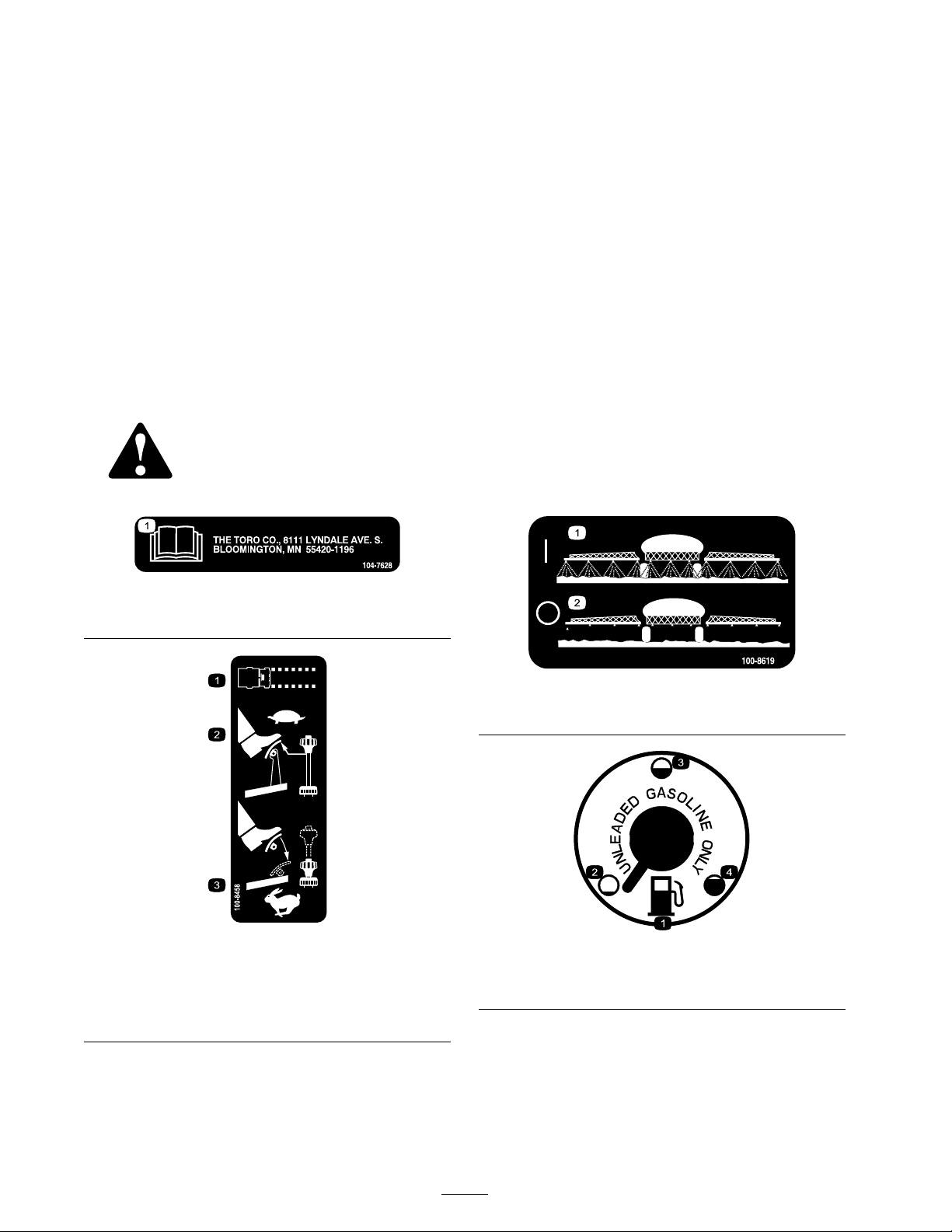
104-7628
1. Read the Operator’s Manual.
100-8458
1. Machine speed
2. To set the machine to a slow speed, reduce pressure on the
accelerator and pull up on the speed limiter.
3. To set the machine to a fast speed, press the accelerator
pedal and push down on the speed limiter.
100-8619
1. Spray on
100-8386
1. Fuel 3. Half-full
2. Empty
2. Spray off
4. Full
8
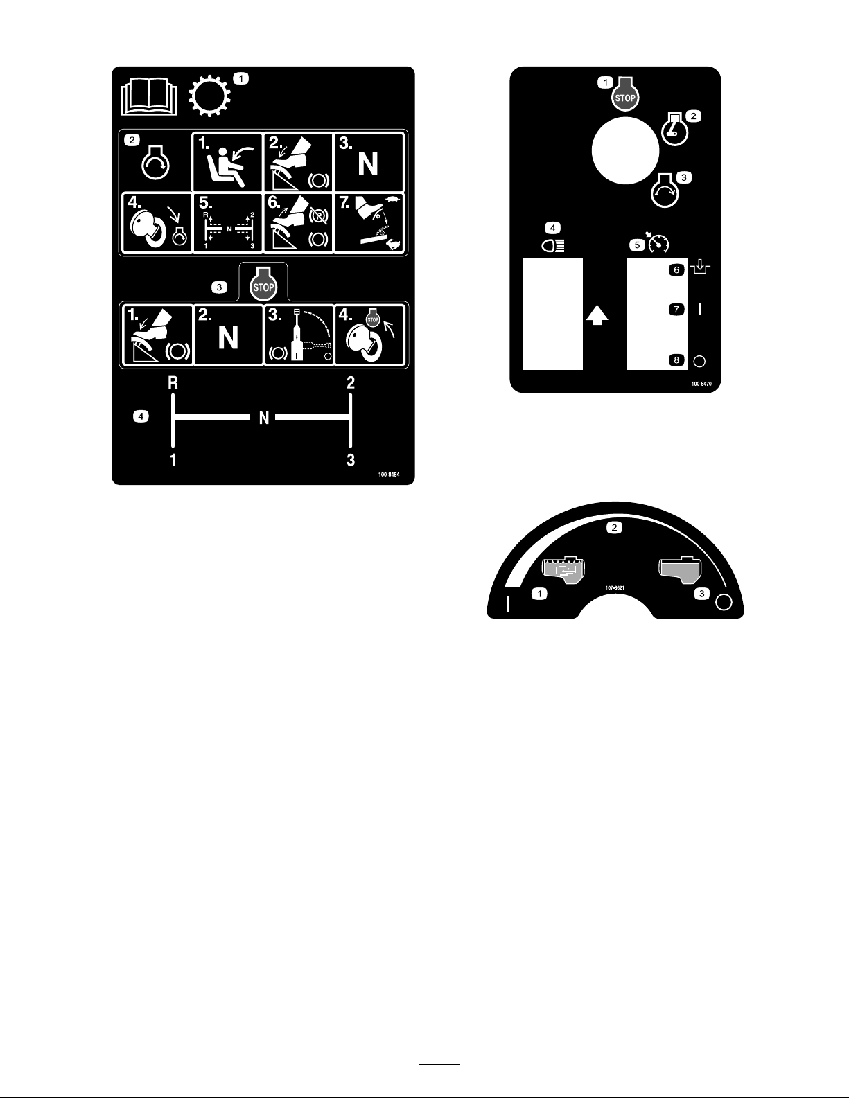
100-8454
1. Read the Operator’s Manual for information on the
transmission.
2. To start the engine, sit on the operator’s seat, press the
brake, set the range selector to Neutral, turn the ignition
key to Engine-start, set the range selector to the desired
gear, release the brake and parking brake, and press the
accelerator pedal to the desired speed.
3. To stop the engine, press the brake, set the range selector
to Neutral, set the brake, and turn the ignition key to
Engine-stop.
4. Range selector gear pattern
100-8470
1. Engine—stop
2. Engine—run
3. Engine—start
4. Headlights 8. Off
107-8621
1. Agitation on
2. Continuous variable setting
5. Neutral engine speed lock
6. Engage
7. On
3. Agitation off
9
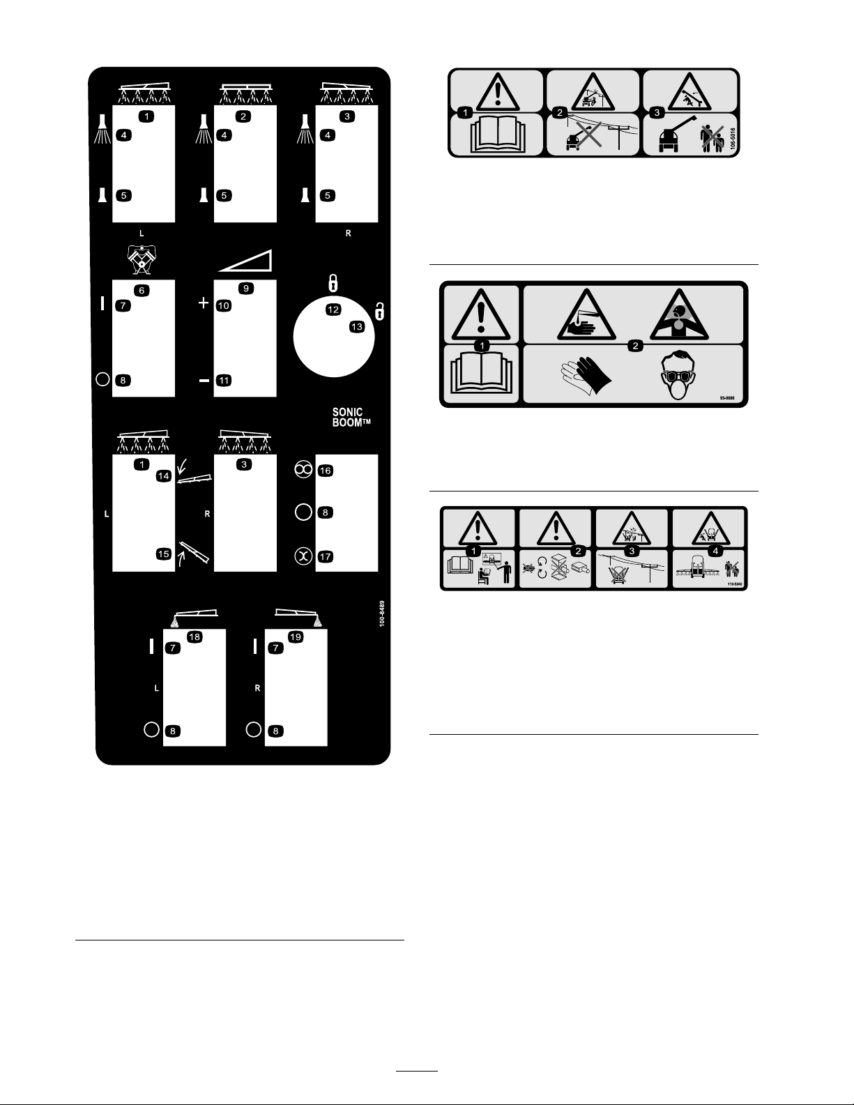
106-5016
1. Warning—read the Operator’s Manual .
2. Electric shock hazard, overhead power lines—stay away from
overhead power lines.
3. Crushing hazard, boom—keep bystanders a safe distance
from the machine.
93-0688
1. Warning—read the Operator’s Manual .
2. Caustic liquid/chemical burn and toxic gas inhalation
hazards—wear hand, skin, eye, and respiratory protection.
100-8489
1. Left boom
2. Center boom 12. Locked
3. Right boom 13. Unlocked
4. Spray on
5. Spray off 15. Raise the boom.
6. Pump
7. On
8. Off 18. Left boom foam marker
9. Continuous variable
setting, spray pressure
10. Increase
11. Decrease
14. Lower the boom.
16. Automatic
17. Manual
19. Right boom foam marker
110-5240
1. Warning—read the Operator’s Manual and receive training
before operating.
2. Warning—stay away from moving parts, do not operate
with covers removed.
3. Electric shock hazard, overhead power lines—stay away from
overhead power lines.
4. Crushing hazard, boom—keep bystanders a safe distance
from the machine.
10

110-5143
1. Warning—read the Operator’s Manual .
2. Tipping Hazard—drive slowly over rough terrain and when
turning.
3. Falling and arm/leg injury hazards—do not carry passengers
and keep arms and legs inside of the vehicle at all times.
4. To stop the engine, press the brake, move the range selector
to Neutral, set the parking brake, release the brake pedal,
turn the ignition key to Engine-stop, and remove the key.
107-8640
1. Warning—read the Operator’s Manual ; use fresh, clean water
for rinsing the tank.
106-5051
1. Warning—read the Operator’s Manual ; use fresh, clean water
for rst-aid washing.
108-3307
1. Warning—do not enter the tank.
108-3309
1. Total area 8. Width
2. Boom select
106-1355
3. Speed 10. Speed calibration
4. Units of measure 11. Sub volume
5. Select units 12. Total volume
6. Application rate 13. Flowmeter calibration
7. Sub area
9. Distance
11
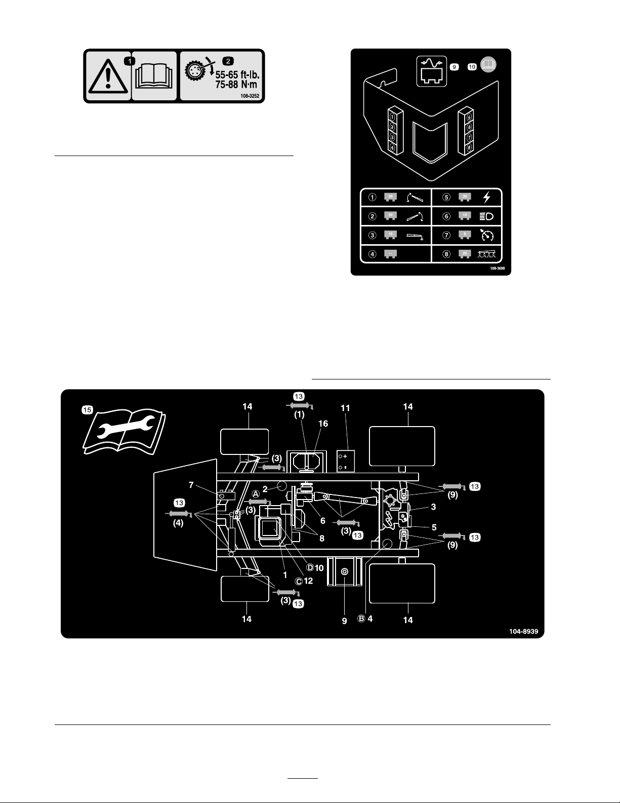
1. Warning—read the
Operator’s Manual .
108-3252
2. Torque lug nuts to 55-65
ft-lb (75-88 N·m).
108-3699
1. 3o amp fuse, left boom
actuator
2. 3o amp fuse, right boom
actuator
3. 15 amp fuse, foam marker 8. 20 amp fuse, spray system
4. Empty
5. 30 amp fuse, power
6. 10 amp fuse, headlights
7. 5 amp fuse, cruise control
9. Fuse panel
10. Read the Operator’s Manual
for more information.
104-8939
1. Engine oil level (dipstick)
2. Engine oil lter 6. Gear box uid level 10. Fuel lter
3. Transaxle/hydraulic uid
level (dipstick)
4. Transaxle hydraulic lter 8. Belts, steering and drive 12. Air cleaner
5. Hydraulic strainer 9. Fuel, unleaded only
7. Brake uid
11. Battery
12
13. Grease
14. Tire pressure
15. Read the instructions before
servicing or performing
maintenance.
16. Pump

Setup
Loose Parts
Use the chart below to verify that all parts have been shipped.
Step
90 degree tting
Quick coupler
Hose adapter
1
2
3
4
Fill receptacle bracket
Flange-head bolt, 5/16 x 3/4 inch
Anti-siphon hose
Spray Pro Monitor
Spray Pro Decal
Bracket
Flange-head bolt, 3/4 inch
Flange nut, 1/4 inch
Knob
Washer
Carriage bolt
No parts required
Ignition key
Operator’s Manual
Engine Operator’s Manual
Parts Catalog
Operator Training Material
Registration Card
Pre-delivery Inspection Sheet
Description
Qty.
1
1
1
1
1
1
1
1
1
2
2
2
2
2
–
1
1
1
1
1
1
1
Install the anti-siphon ll receptacle.
Install the Spray-Pro monitor.
Check the boom hinge springs.
Read the manuals and view the
training material before operating
the machine.
Use
Note: Deter mine the left and right sides of the
mac hine from the nor mal operating position.
13
Step
3. Install the hose adapter into the quic k coupler
( Figure 3 ).
4. Loc k the adapter into place b y swinging the
1
lev ers to w ard the adapter and then secure them
with the hair pin cotters ( Figure 3 ).
Installing the Anti-siphon
Fill Receptacle
Parts needed for this step:
1
90 degree tting
1
Quick coupler
1
Hose adapter
1
Fill receptacle bracket
1
Flange-head bolt, 5/16 x 3/4 inch
1
Anti-siphon hose
Procedure
1. Place the fill rece ptacle brac k et o v er the
threaded hole in the tank and secure it with a
flang e-head bolt (5/16 x 3/4 inc h) ( Figure 3 ).
5. Install the anti-siphon hose through the larg e
opening on the brac k et and onto the barbed
end of the 90 deg ree elbo w fitting ( Figure 3 ).
Important: Do not lengthen the hose to
allo w contact with the tank fluids.
Step
2
Installing the Spray Pro
Monitor
Parts needed for this step:
1
Spray Pro Monitor
1
Spray Pro Decal
1
Bracket
2
Flange-head bolt, 3/4 inch
2
Flange nut, 1/4 inch
2
Knob
2
Washer
2
Carriage bolt
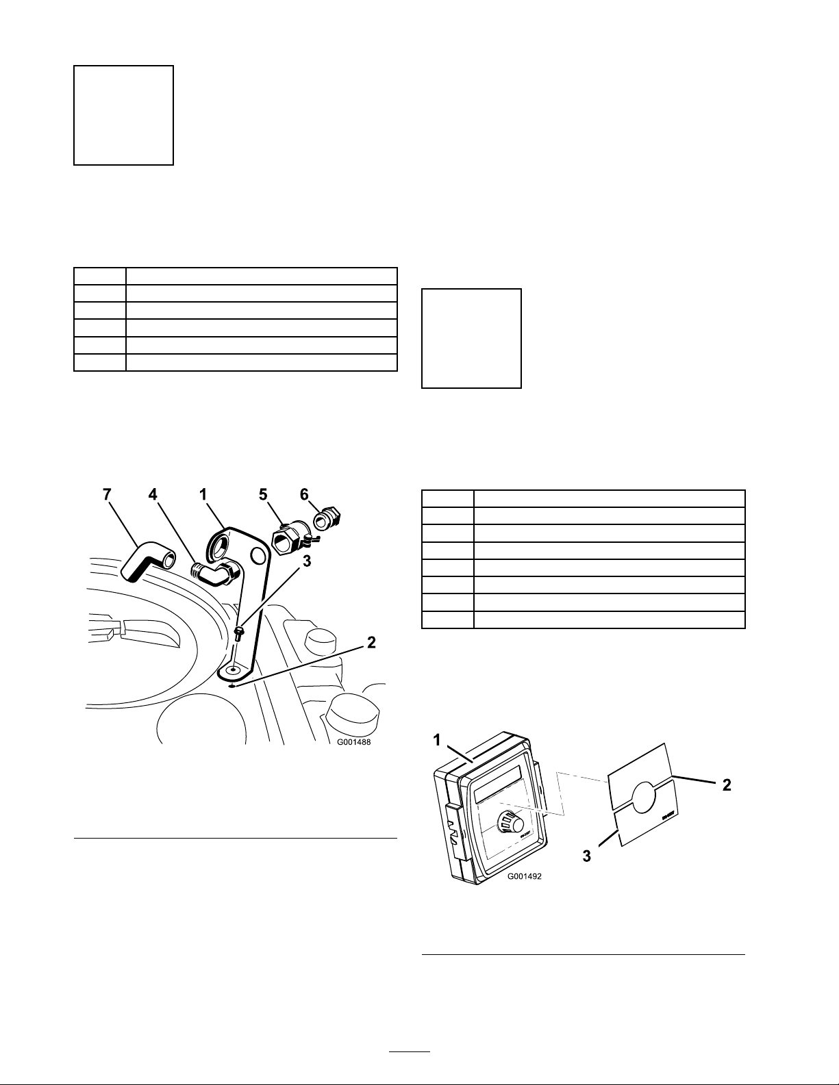
Figure 3
1. Fill receptacle bracket 5. Quick coupler
2. Threaded hole in the tank 6. Hose adapter
3. Flange bolt, 5/16 x 3/4 inch 7. Anti-siphon hose
4. 90 degree elbow tting
2. Place the threaded end of the 90 deg ree elbo w
fitting through the brac k et and thread the
quic k coupler onto it, securing it to the brac k et
( Figure 3 ).
Note: Install the fitting with the open end
pointing to w ard the larg e opening in the
brac k et and to w ard the tank opening so the
w ater will arc into the tank when y ou fill it.
Procedure
1. Install the Spra y Pro Decal to the monitor
( Figure 4 ).
Figure 4
1. Spray pro monitor
2. Decal, Upper half
3. Decal, Lower half
Note: Be sure to orient the decal as sho wn
in Figure 20 .
14
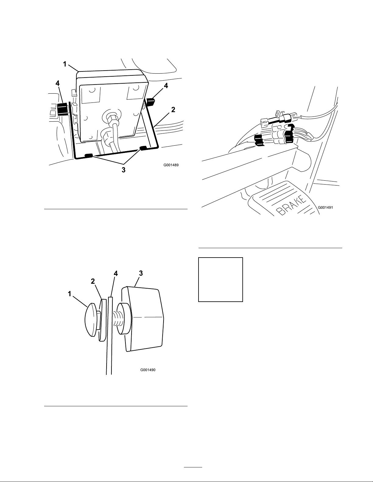
2. Install the monitor brac k et on the dash
( Figure 5 ) using 2 flang e-head bolts
(1/4 x 3/4 inc h) and 2 flang e n uts (1/4 inc h).
Figure 5
1. Spray Pro monitor
2. Bracket 4. Knob
3. Flange-head bolts,
1/4 x 3/4 inch
6. Install the Spra y Pro monitor o v er the car riag e
bolt heads ( Figure 5 ) and tighten the knobs to
secure it.
7. Connect the Spra y Pro wire connectors to
the wire connectors located under the dash
( Figure 7 ).
3. Loosely install the 2 car riag e bolts , r ubber
w ashers , and knobs on the brac k et as illustrated
in Figure Figure 5 and Figure 6 .
Note: Install the car riag e bolts and r ubber
w ashers inside of the brac k et and the knobs
on the outside .
Figure 6
1. Carriage bolt 3. Knob
2. Rubber washer 4. Bracket
4. R emo v e the larg e g rommet from the hole in
the dash and thread the cables on the monitor
through the g rommet and the dash.
5. Install the g rommet into the dash.
Figure 7
1. Connectors from the
sprayer
2. Connectors from the
monitor
Step
3
Checking the Boom Hinge
Springs
No Parts Required
Procedure
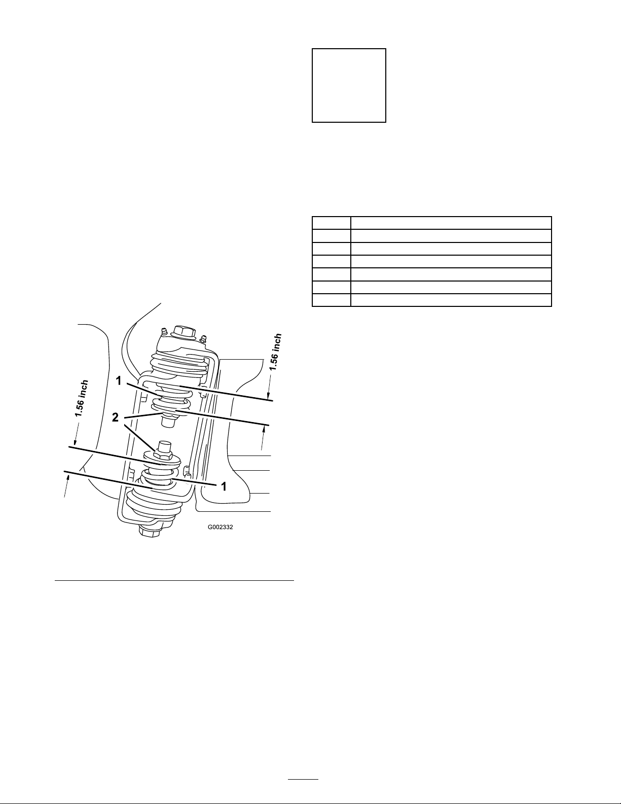
Important: Operating the spray system
with the boom hinge springs under the
incor r ect compr ession could dama ge the
boom assembl y . Measur e the springs and use
the jam n ut to compr ess the springs to 1.56
inches if necessar y .
T he spra yer is shipped with the boom extensions
swung forw ard to facilitate pac kaging of the
mac hine . T he springs are not fully tightened at
15
the time of man ufacture to allo w the booms to
be in this position for transit. Before operating
the mac hine , the springs m ust be adjusted to the
cor rect compression.
1. If necessar y , remo v e the pac king components
that secure the right and left extension booms
during shipping .
2. Suppor t the booms while they are extended
to the spra y position.
Step
4
Completing the Setup:
Learning more about your
product.
3. At the boom hing e , measure the compression
of the upper and lo w er springs while the booms
are in their extended position ( Figure 8 ).
A. All springs m ust be compressed until they
measure 1.56 inc hes .
B . Use the jam n ut to compress any spring
that measure g reater than 1.56 inc hes .
Parts needed for this step:
1
Ignition key
1
Operator’s Manual
1
Engine Operator’s Manual
1
Parts Catalog
1
Operator Training Material
1
Registration Card
1
Pre-delivery Inspection Sheet
Procedure
1. R ead the man uals .
2. View the Operator training material.
3. Complete the registration card and retur n to
T oro .
4. Store the documentation in a safe place .
Figure 8
1. Boom hinge spring
2. Jam nut
4. R e peat the procedure for eac h spring on both
boom hing es .
5. Mo v e the booms into the transpor t “X”
position. See Operating the Booms in
Operation , pag e 25 for more infor mation.
16
Product Overview
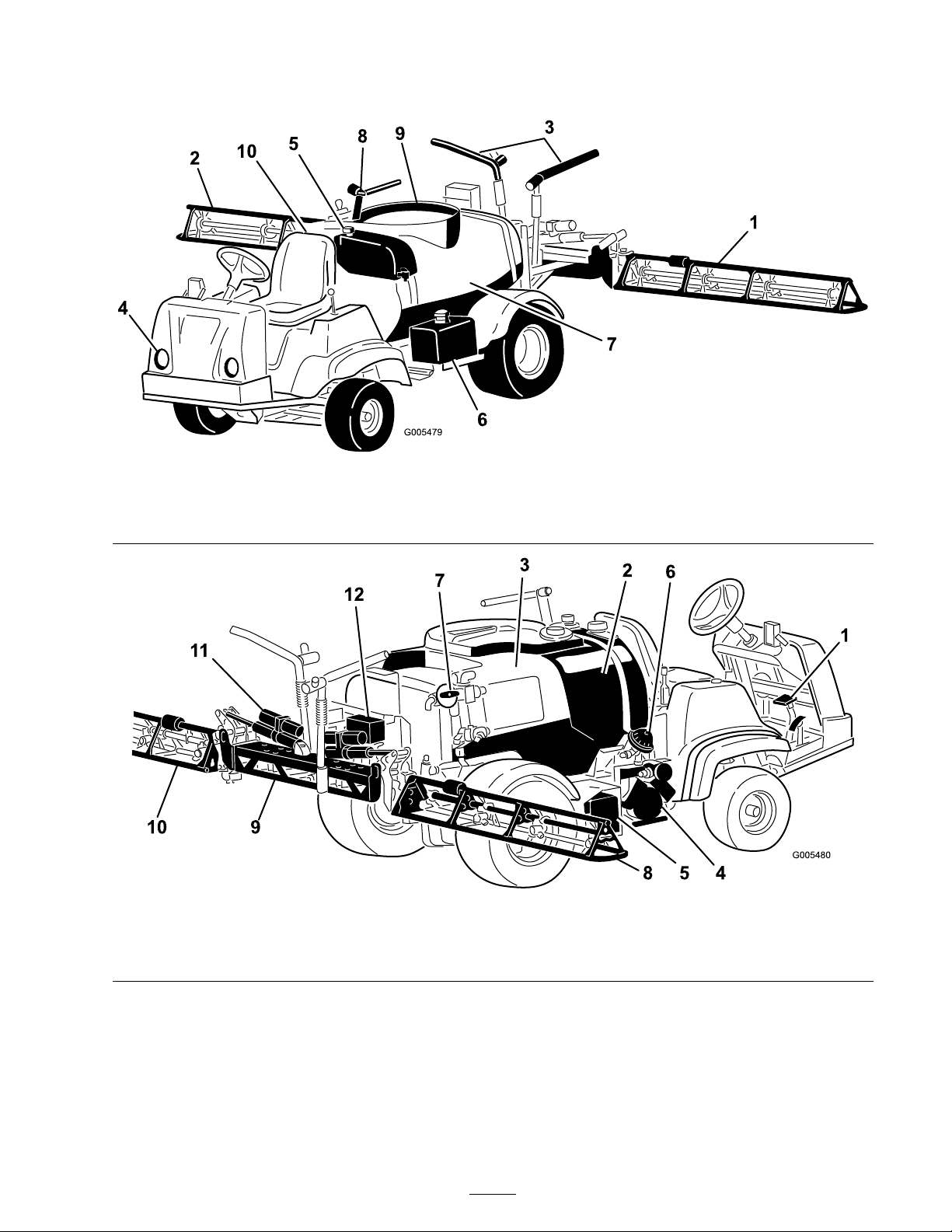
Figure 9
1. Left boom 4. Headlight 7. Chemical tank
2. Right boom 5. Fresh water tank 8. Anti-Siphon Receptacle
3. Boom transport cable 6. Gas tank 9. Tank lid
10. Operator’s position
Figure 10
1. Pedals
2. Rinse tank
3. Chemical tank 6. Pump pressure dampener 9. Center boom 12. Valve cluster
4. Pump
5. Battery
7. Agitation control valve 10. Left boom
8. Right boom 11. Boom control cylinder
17
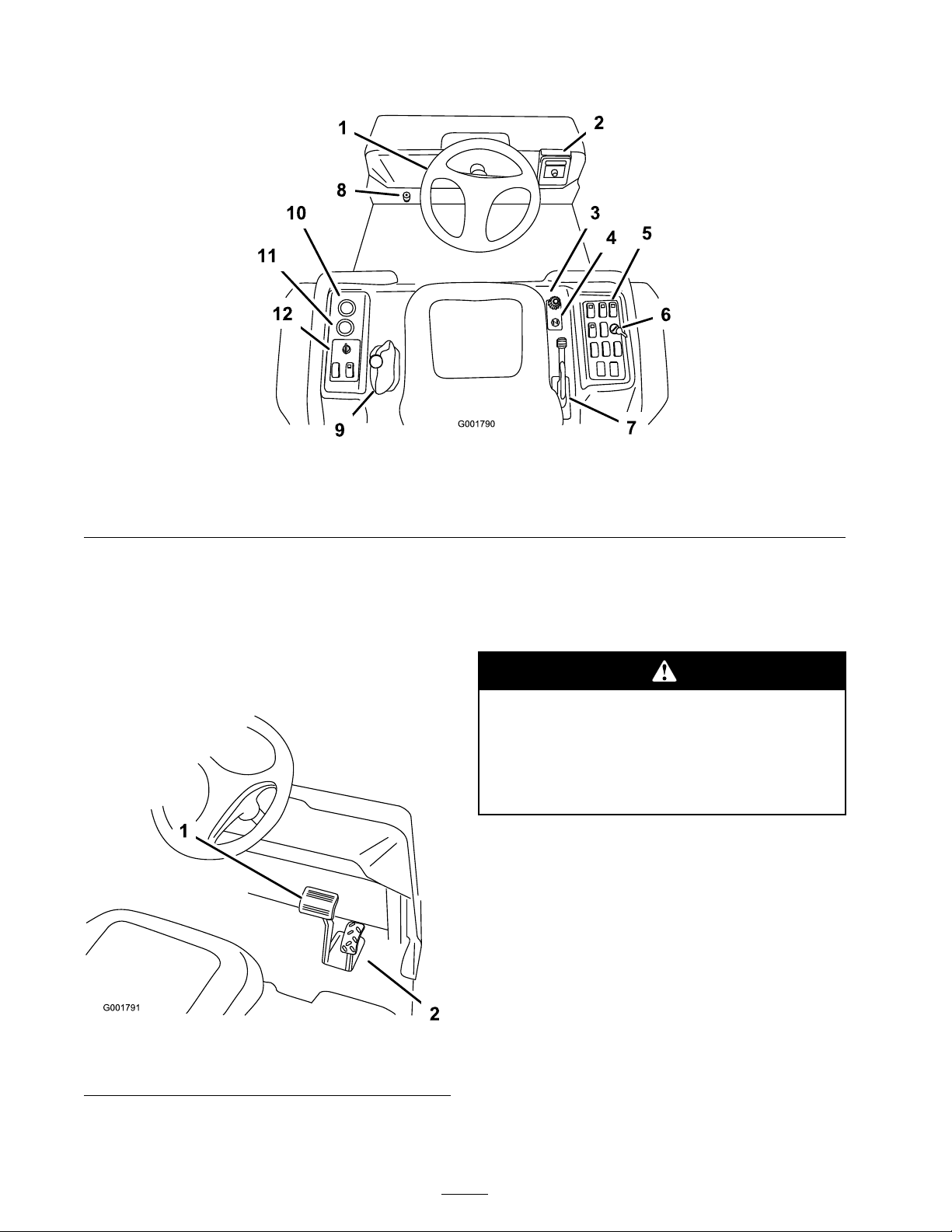
Controls
Figure 11
1. Steering wheel 4. Choke 7. Parking brake 10. Voltmeter
2. Spray-Pro monitor
3. Speed limiter 6. Rate lockout switch 9. Range Selector 12. Vehicle controls
5. Sprayer controls 8. Master boom foot switch
11. Hour meter
Accelerator Pedal
T he accelerator pedal ( Figure 12 ) gi v es y ou
the ability to v ar y g round speed of the spra yer .
Pressing the pedal increases g round speed.
R eleasing the pedal will slo w the spra yer and the
engine will idle .
Figure 12
1. Brake pedal 2. Accelerator pedal
Brake Pedal
Use the brak e pedal to stop or slo w the spra yer
( Figure 12 ).
Brak es can become w or n or can be adjusted
incor r ectl y r esulting in per sonal injur y .
If brak e pedal tra v els to within 1 inch
(2.5 cm) of the spray er floor board, the
brak es must be adjusted or r epair ed.
Parking Brake
T he parking brak e is a larg e lev er to the right of
the seat. ( Figure 13 ). Eng ag e the parking brak e
whenev er y ou plan on lea ving the seat to prev ent
accidental mo v ement of the spra yer . T o eng ag e
the parking brak e , pull up and bac k on the lev er .
T o diseng ag e , push it forw ard and do wn. If the
spra yer is park ed on a stee p g rade , apply the
parking brak e and place bloc ks at the do wnhill
side of the wheels .
18
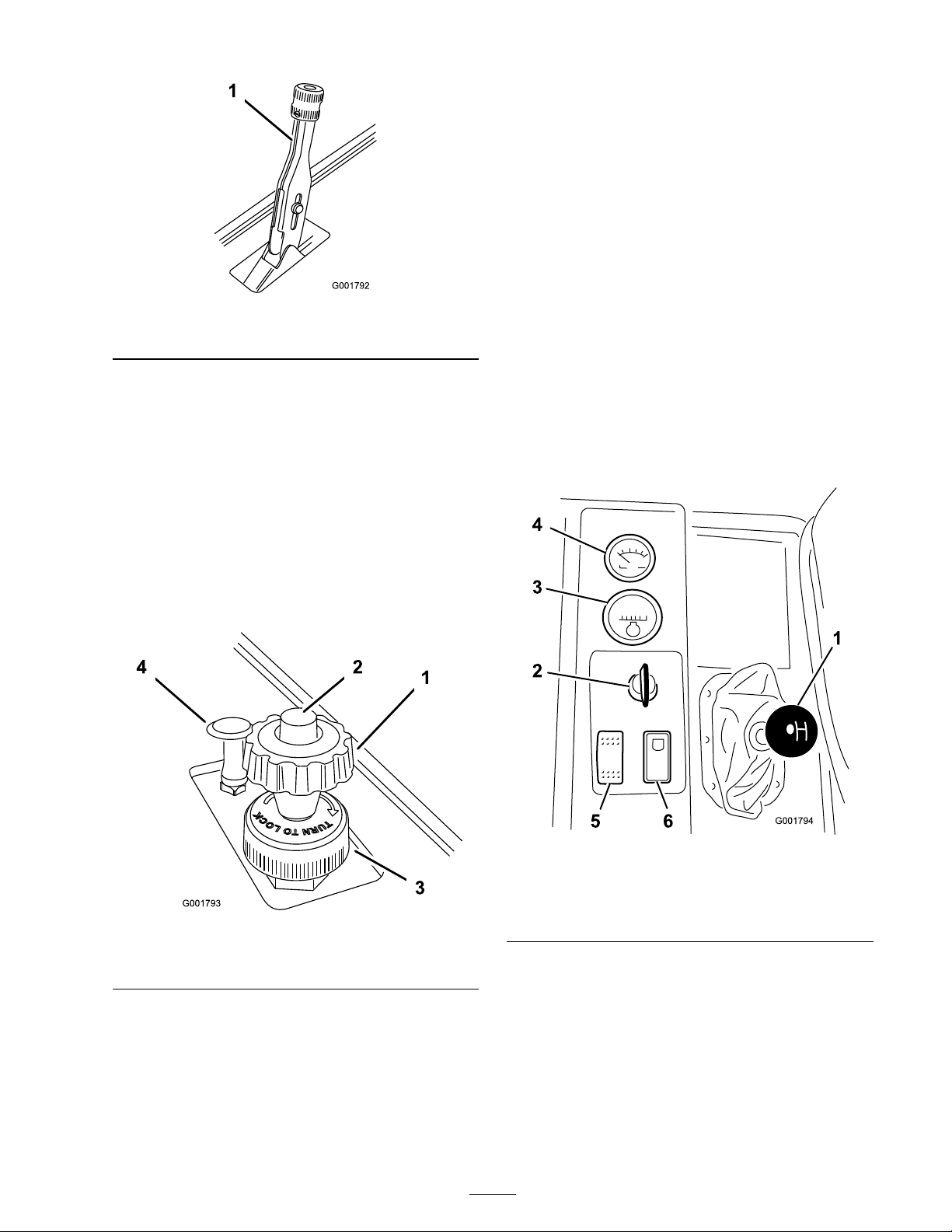
Figure 13
1. Parking brake lever
Speed Limiter
T he speed limiter is a larg e knob located to the
right of the seat ( Figure 14 ). It allo ws y ou to set
the maxim um do wnw ard tra v el of the accelerator
pedal, thereb y limiting the maxim um r pm of the
engine . T his indirectly limits the speed of the
spra yer .
smoothly . As soon as possible , push the control
do wn to the Off position. A w ar m engine requires
little or no c hoking .
Range Selector
T he rang e selector , located to the left of the seat,
has 5 positions: 3 forw ard speeds , Neutral, and
R ev erse ( Figure 15 ). T he engine will star t only
when the rang e selector is in the Neutral position.
Y ou m ust also fully press the brak e with the
spra yer stopped to c hang e rang es .
Important: Do not shift out of or change
ranges while the v ehicle is mo ving . Attempting
to change ranges while the v ehicle is mo ving
can dama ge the transmission. Onl y stopping
the spray er completel y , and full y enga ging the
brak e will safel y disenga ge the locking pin
and allo w the ranges to be changed.
Note: T he v ehicle controls the application rate
based on y our speed and y ou do not need to k ee p
a constant speed to apply at a constant rate .
Figure 14
1. Speed limiter knob 3. Locking ring
2. Speed limiter button 4. Choke control
Choke Control
T he c hok e control is a small knob to the right
of the seat. ( Figure 14 ). T o star t a cold engine ,
pull the c hok e control up . After the engine star ts ,
regulate the c hok e to k ee p the engine r unning
Figure 15
1. Range Selector 4. Voltmeter
2. Ignition switch 5. Headlight switch
3. Hour meter
6. Neutral engine speed lock
switch
Ignition Switch
T he ignition switc h ( Figure 15 ), used to star t
and stop the engine , has 3 positions: Stop , R un,
and Star t. R otate the k ey cloc kwise to the Star t
position to star t the engine and release it to the
R un position when star ted. R otate the k ey to the
Stop position to stop the engine .
19
Hour Meter
T he hour meter ( Figure 15 ) indicates the total
n umber of hours the engine has r un. T he hour
meter star ts to function whenev er the k ey is tur ned
to the R un position.
Voltmeter
T he v oltmeter ( Figure 15 ) indicates the lev el of
c harg e in the batter y . W hen the batter y is fully
c harg ed, the v oltmeter will read in the center of
the dial when the k ey is in the R un position with
the engine off . W hen the engine is r unning the
v oltmeter needle should be to the right.
Figure 16
1. Master boom switch
Headlight Switch
T og gle the switc h to operate the headlights
( Figure 15 ). Push it forw ard to tur n the lights on
and rearw ard to tur n them off .
Neutral Engine Speed Lock Switch
W hen the rang e selector is in the Neutral position,
y ou can use the accelerator pedal to speed up the
engine , then push this switc h forw ard to set the
engine at that speed. T his is necessar y to r un the
c hemical agitation while stationar y or operating
attac hments suc h as the hand spra yer ( Figure 15 ).
Important: T he range selector must be in
the neutral position f or the s witch to w or k.
Fuel Gauge
T he fuel g aug e is located on top of the fuel tank,
on the right side of the mac hine and sho ws the
amount of fuel in the tank.
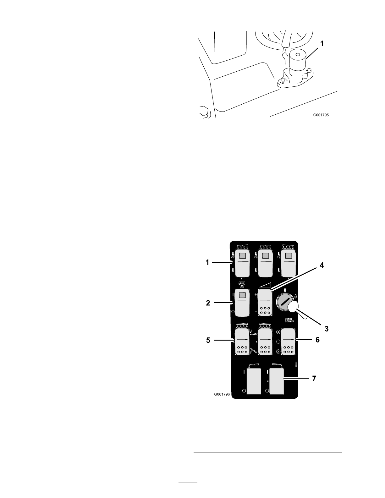
Boom Switches
T he boom switc hes are located at the front
of the control panel to the right of the seat
( Figure 17 ). T og gle eac h switc h forw ard to tur n
the cor responding boom section on and rearw ard
to tur n them off . W hen the switc h is tur ned on,
a light on the switc h illuminates . T hese switc hes
will only affect the spra y system when the master
boom switc h is on.
Master Boom Switch
T he master boom switc h is located on the floor
board of the mac hine cab and to the left of the
operator . It allo ws y ou to star t or stop the spra y
operation. Press the switc h with y our foot to
enable or disable the spra y system ( Figure 16 ).
W hen the master switc h is off , the Spra y Pro
monitor screen reads “Hold."
Figure 17
1. Boom switches, left, right
and center
2. Pump switch 6. Sonic boom switch
3. Rate lockout key 7. Foam marker switch, left
4. Application rate switch
20
5. Boom lift switch, left and
right
and right

Pump Switch
Rate Control Valve
T he pump switc h is located on the control panel
to the right of the seat ( Figure 17 ). T og gle this
switc h forw ard to r un the pump or rearw ard to
stop the pump .
Important: Onl y enga ge the pump s witch
when the engine is at lo w idle to a v oid
dama ging the pump dri v e.
Application Rate Switch
T he application rate switc h is located on the
control panel to the right of the seat Figure 17 ).
Press and hold the switc h forw ard to increase
the spra y system pressure , or press and hold it
rearw ard to decrease pressure .
Rate Lockout Key Switch
T he rate loc k out k ey switc h is located on the
control panel to the right of the seat ( Figure 17 ).
T ur n the k ey countercloc kwise to the loc k ed
position to disable the application rate switc h,
thereb y k ee ping any one from accidentally c hanging
the application rate . T ur n the k ey cloc kwise to the
unloc k ed position to enable the application rate
switc h.
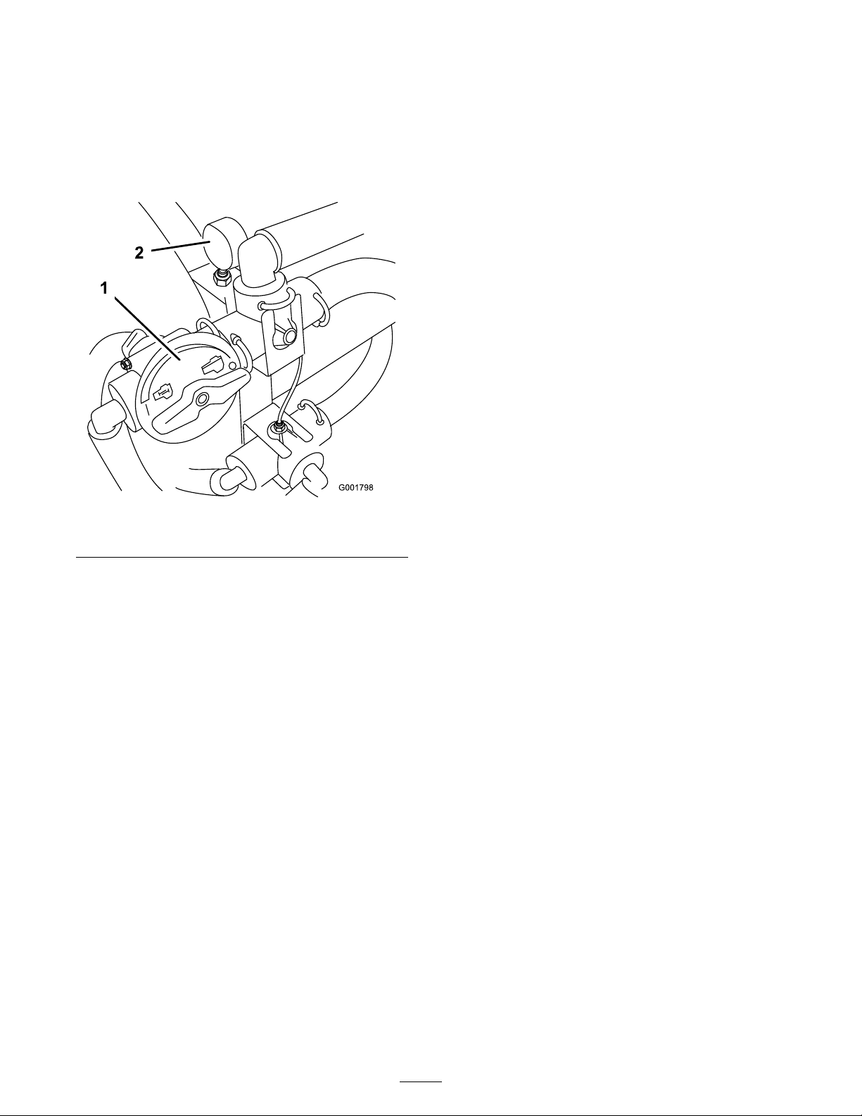
T his v alv e , located behind the tank ( Figure 18 ),
controls the amount of fluid that is routed to the
booms b y directing fluid flo w to the booms or
the b ypass hose to the tank. Y ou can control this
v alv e in tw o w a ys: the application rate switc h or
man ually . T o control it man ually , y ou need to
disconnect the wire connector on the v alv e , then
y ou can rotate the knob on top of the v alv e to
man ually obtain the desired pressure .
Figure 18
1. Rate control valve 3. Boom valves
2. Flowmeter
Important: Do not attempt to mo v e the
range selector while the rate lock out k ey is
enga ged. F orcing the selector while mo ving
will dama ge lock out k ey components.
Boom Lift
T he boom lift switc hes are used to raise the left
and right boom respecti v ely .
Sonic Boom (Optional)
T he Sonic Boom switc h is a roc k er switc h used to
operate the Sonic Boom. T og gle switc h forw ard
for automatic , rearw ard for man ual and center for
Off .
Foam Marker Switch Locations
(Optional)
If y ou install the electric boom lift, sonic boom,
and foam mark er kit, y ou will add switc hes to the
control panel for controlling their operation. T he
spra yer comes with plastic plugs in these locations .
Flowmeter
T he flo wmeter measures the flo w rate of the fluid
for use b y the Spra y Pro™ system ( Figure 18 ).
Boom Valves
T hese v alv es tur n the three booms on or off
( Figure 18 ). If y ou do not ha v e a boom installed
or do not w ant a boom to be able to be tur ned
on, y ou can man ually operate eac h v alv e b y
disconnecting the wire connector in the v alv e , then
rotate the knob on the v alv e cloc kwise to tur n the
v alv e off or countercloc kwise to tur n it on.
Boom Bypass Valves
T he boom b ypass v alv es redirect the fluid flo w for
a boom to the tank when y ou tur n off the boom
section. Y ou can adjust these v alv es to ensure that
the boom pressure remains constant no matter
ho w many booms are on. R efer to Calibrating the
Boom Bypass V alv es , in the Operation section.
21
Agitation Control Valve
Pressure Gauge
T his v alv e is located on the right side of the tank
( Figure 19 ). T ur n the knob on the v alv e to the
9 o’cloc k position to tur n on the tank agitation
and to the 3 o’cloc k position to tur n off the tank
agitation.
Figure 19
1. Agitation control valve
2. Pressure gauge
T he pressure g aug e is located to the right of the
tank ( Figure 19 ). T his g aug e sho ws the pressure
of the fluid in the system in psi and kP a. Use the
g aug e to adjust the b y-pass v alv es whenev er y ou
c hang e nozzles .
Anti-siphon Fill Receptacle
T o the front of the tank co v er is a hose rece ptacle
with a threaded fitting, a 90 deg ree barbed fitting,
and a shor t hose whic h y ou can direct to w ard
the tank opening . T his rece ptacle allo ws y ou to
connect a w ater hose to it and fill the tank with
w ater without contaminating the hose with the
c hemicals in the tank.
Important: Do not lengthen the hose to
allo w contact with the tank fluids.
Note: F or agitation to w ork, the pump m ust
be on and the engine m ust be r unning abo v e an
idle . If y ou stop the spra yer and need agitation on,
place the rang e selector in the Neutral position, set
the parking brak e , press the accelerator pedal to
the floor , tur n the pump On and tur n the neutral
engine speed loc k On.
22

Spray Pro™ Monitor
T he Spra y Pro monitor displa ys and monitors
v arious system perfor mance data suc h as v ehicle
speed and application rates . It does not control
the application rate .
T he monitor has an LCD screen that displa ys the
data y ou select, a selection dial, and 4 buttons for
calibrating the monitor ( Figure 20 ).
Figure 20
1. LCD screen
2. Selection dial
3. Total area 8. Sub Area 13. Decrease, calibration button 18. Speed calibration
4. Speed 9. Sub volume 14. Increase, calibration button 19. Flowmeter calibration
5. Units of measure 10. Total volume 15. Boom selection
Monitor Display Selection Dial
Use the dial to set the LCD screen displa y to the
follo wing:
• T otal ar ea
Displa ys the total acres (US), hectares (SI), or
sq feet (TURF) that y ou ha v e co v ered since
y ou last pressed the R eset calibration button
for this setting .
• Speed
Displa ys the g round speed in miles per hour (if
the Units of Measure is set to US or TURF) or
kilometers per hour (if the Units of Measure
is set to SI).
• Units of Measur e
Displa ys the cur rent measurement unit
selection as follo ws:
6. Application rate 11. Reset, calibration button 16. Select units
7. Distance
12. Calibrate, calibration button 17. Width
20. LED
– SI (metric system)
– TURF (as US but the v olumes are in US
g allons per 1000 sq ft instead of US g allons
per acre)
• Application R ate
Displa ys the application rate in US g allons per
acre (US), liters pre hectare (SI), or US g allons
per 1000 sq ft (TURF).
• Sub Ar ea
Displa ys the total acres (US), hectares (SI), or
sq feet (TURF) that y ou ha v e co v ered since
y ou last pressed the R eset calibration button
for this setting, without affecting the T otal
Area displa y . If y ou press the R eset calibration
button, the Sub V olume resets .
• Distance
– US (United States measuring system)
23
 Loading...