

Toro 41198 Multi-Pro 1250, Multi-Pro 1250, 41177, 41179 Operator's Manual
FormNo.3365-118RevB
g013107
Multi-Pro
ModelNo.41198—SerialNo.310000001andUp
®
1250TurfSprayer
ToregisteryourproductordownloadanOperator'sManualorPartsCatalogatnocharge,gotowww.Toro.com.OriginalInstructions(EN)
TheMulti-Pro®turfsprayerisadedicatedturfspray
G001788
1
applicationvehicleandisintendedtobeusedby
professional,hiredoperatorsincommercialapplications.
Itisprimarilydesignedforsprayingonwell-maintained
lawnsinparks,golfcourses,sportselds,andon
commercialgrounds.
ThisproductcomplieswithallrelevantEuropean
directives,fordetailspleaseseetheseparateproduct
specicDeclarationofConformity(DOC)sheet.
WARNING
CALIFORNIA
Proposition65Warning
Theengineexhaustfromthisproduct
containschemicalsknowntotheStateof
Californiatocausecancer,birthdefects,
orotherreproductiveharm.
Important:Thisengineisnotequippedwitha
sparkarrestermufer.ItisaviolationofCalifornia
PublicResourceCodeSection4442touseoroperate
theengineonanyforest-covered,brush-covered,or
grass-coveredland.Otherstatesorfederalareas
mayhavesimilarlaws.
ThissparkignitionsystemcomplieswithCanadian
ICES-002.
Theenclosed
Engine Owner’ s Man ual
issupplied
forinformationregardingtheUSEnvironmental
ProtectionAgency(EPA)andtheCalifornia
EmissionControlRegulationofemissionsystems,
maintenance,andwarranty.Replacementsmaybe
orderedthroughtheenginemanufacturer.
Introduction
Figure1
1.Locationofthemodelandserialnumbers
ModelNo.
SerialNo.
Thismanualidentiespotentialhazardsandhas
safetymessagesidentiedbythesafetyalertsymbol
(Figure2),whichsignalsahazardthatmaycauseserious
injuryordeathifyoudonotfollowtherecommended
precautions.
Figure2
1.Safetyalertsymbol.
Thismanualusestwootherwordstohighlight
information.Importantcallsattentiontospecial
mechanicalinformationandNoteemphasizesgeneral
informationworthyofspecialattention.
Readthismanualcarefullytolearnhowtooperateand
maintainyourproductproperly.Theinformationinthis
manualcanhelpyouandothersavoidinjuryandproduct
damage.AlthoughTorodesignsandproducessafe
products,youareresponsibleforoperatingtheproduct
properlyandsafely.YoumaycontactTorodirectlyat
www.T oro.comforproductandaccessoryinformation,
helpndingadealer,ortoregisteryourproduct.
Wheneveryouneedservice,genuineToroparts,or
additionalinformation,contactanAuthorizedService
DealerorToroCustomerServiceandhavethemodel
andserialnumbersofyourproductready.Figure1
illustratesthelocationofthemodelandserialnumbers
ontheproduct.
©2011—TheT oro®Company
8111LyndaleAvenueSouth
Bloomington,MN55420
Contents
Introduction.................................................................2
Safety...........................................................................4
SafeOperatingPractices.......................................4
ChemicalSafety....................................................4
BeforeOperating.................................................5
WhileOperating...................................................5
Maintenance.........................................................7
SoundPower........................................................7
SoundPressure.....................................................7
Hand-ArmVibration............................................7
WholeBodyVibration..........................................7
SafetyandInstructionalDecals.............................8
Contactusatwww.T oro.com.
2
PrintedintheUSA.
AllRightsReserved

Setup..........................................................................13
1InstallingtheAnti-siphonFill
Receptacle......................................................13
2InstallingtheSprayProMonitor.......................14
3CheckingtheBoomHingeSprings...................15
4AdjustingtheBoomstoLevel..........................16
5CompletingtheSetup:Learningmoreabout
yourproduct...................................................16
ProductOverview......................................................17
Controls.............................................................18
Specications.....................................................24
Operation...................................................................25
ThinkSafetyFirst...............................................25
BeforeDrivingtheSprayerfortheFirst
Time..............................................................25
Pre-StartingChecks............................................26
DrivingtheSprayer.............................................27
NewSprayerBreak-In........................................27
OperatingtheSprayer.........................................28
FillingtheFreshWaterTank...............................28
FillingtheSprayTank.........................................29
OperatingtheBooms.........................................29
Spraying.............................................................30
SprayingTips.....................................................30
CleaningtheSprayer...........................................30
CalibratingtheSprayProMonitor.......................33
CalibratingtheBoomBypassValves....................35
Pump.................................................................35
TransportingtheSprayer....................................36
TowingtheSprayer.............................................36
Maintenance...............................................................37
RecommendedMaintenanceSchedule(s)................37
DailyMaintenanceChecklist...............................38
NotationforAreasofConcern...........................39
PremaintenanceProcedures....................................40
JackingtheSprayer.............................................40
Lubrication.............................................................41
GreasingtheSprayer...........................................41
GreasingtheBoomHinges.................................42
GreasingtheActuatorRodBearings...................42
EngineMaintenance...............................................44
CheckingtheAirIntakeScreen...........................44
ServicingtheAirCleaner....................................44
ServicingtheEngineOil.....................................45
ChangingtheSparkPlugs...................................46
FuelSystemMaintenance.......................................47
ReplacingtheFuelFilter.....................................47
DrainingtheFuelTank.......................................47
ElectricalSystemMaintenance................................48
Fuses..................................................................48
ServicingtheBattery...........................................48
DriveSystemMaintenance.....................................51
InspectingtheWheels/Tires...............................51
AdjustingtheFrontWheelT oe-In.......................51
BrakeMaintenance.................................................52
CheckingtheBrakeFluid....................................52
InspectingtheBrakes.........................................52
AdjustingtheParkingBrake................................52
BeltMaintenance....................................................53
ServicingtheDriveBelt......................................53
AdjustingtheSteeringPumpBelt........................53
HydraulicSystemMaintenance...............................54
CheckingtheTransaxle/HydraulicFluid.............54
ChangingTransaxle/HydraulicFluid..................54
ReplacingtheHydraulicFilter............................55
SpraySystemMaintenance......................................55
InspectingtheHoses..........................................55
PumpMaintenance.............................................55
AdjustingtheBoomActuator.............................56
EmergencyManualOperationoftheBoom
Actuators.......................................................57
InspectingtheNylonPivotBushings...................57
Cleaning.................................................................58
CleaningtheFlowmeter......................................58
CleaningtheSuctionStrainer..............................58
Storage.......................................................................59
Troubleshooting.........................................................61
Schematics.................................................................65
3

Safety
ChemicalSafety
Improperuseormaintenancebytheoperatororowner
canresultininjury.Toreducethepotentialforinjury,
complywiththesesafetyinstructionsandalwayspay
attentiontothesafetyalertsymbol,whichmeans
CAUTION,WARNING,orDANGER—personal
safetyinstruction.Failuretocomplywiththeinstruction
mayresultinpersonalinjuryordeath.
Supervisors,operators,andservicepersonsshouldbe
familiarwiththefollowingstandardsandpublications:
(Thematerialmaybeobtainedfromtheaddressshown).
•FlammableandCombustibleLiquidsCode:
ANSI/NFPA30
•NationalFireProtectionAssociation:
ANSI/NFPA#505;PoweredIndustrialTrucks
NationalFirePreventionAssociation
BarrymarchParkQuincy,Massachusetts
02269U .S.A.
•SAEJ2258LightUtilityV ehicles
SocietyofAutomotiveEngineers
SAEWorldHeadquarters400CommonwealthDrive
Warrendale,P A15096-0001
•ANSI/UL558;InternalCombustion
EnginePoweredIndustrialTrucks
AmericanNationalStandardsInstitute,Inc.
1430BroadwayNewYork,NewYork10018U.S.A.
orUnderwritersLaboratories333PngstenRoad
Northbrook,Illinois60062U.S.A.
SafeOperatingPractices
WARNING
Thesprayerisanoff-highwayvehicleonlyandis
notdesigned,equipped,ormanufacturedforuseon
publicstreets,roads,orhighways.
Supervisor’sResponsibilities
•Makesurethatoperatorsarethoroughlytrainedand
familiarwiththeOperator’sManual,EngineManual,
andalllabelsonthesprayer.
•Establishyourownspecialproceduresandwork
rulesforunusualoperatingconditions(e.g.slopes
toosteepforsprayeroperation).
WARNING
Chemical substances used in the spray system may
be hazardous and to xic to y ou, bystander s, animals,
plants, soils or other pr oper ty .
•Carefullyreadandfollowthechemical
warninglabelsandMaterialSafetyData
Sheets(MSDS)forallchemicalsusedand
protectyourselfaccordingtothechemical
manufacturer’srecommendations.Forexample,
useappropriatePersonalProtectiveEquipment
(PPE)includingfaceandeyeprotection,gloves,
orotherequipmenttoguardagainstpersonal
contactwiththechemical.
•Keepinmindthattheremaybemorethanone
chemicalusedandinformationoneachshould
beassessed.
R efuse to operate or w or k on the spray er if this
•
inf or mation is not a v aila ble!
•Beforeworkingonaspraysystemmakesurethe
systemhasbeentriplerinsedandneutralized
accordingtotherecommendationsofthe
chemicalmanufacturer(s).
•Verifythereisanadequatesupplyofcleanwater
andsoapnearby,andimmediatelywashoffany
chemicalsthatcontactyou.
•Obtainpropertrainingbeforeusingorhandling
chemicals.
•Usethecorrectchemicalforthejob.
•Followthechemicalmanufacturer’sinstructionsfor
thesafeapplicationofthechemical.
•Handlechemicalsinawellventilatedarea.
•Weargogglesandotherprotectiveequipmentas
instructedbythechemicalmanufacturer.Ensure
thataslittleskinaspossibleisexposedwhileusing
chemicals.
•Havecleanwateravailableespeciallywhenllingthe
spraytank.
•Donoteat,drink,orsmokewhileworkingwith
chemicals.
•Alwayswashyourhandsandotherexposedareasas
soonaspossibleafternishingthework.
•Properlydisposeofunusedchemicalsand
chemicalcontainersasinstructedbythechemical
manufacturerandyourlocalcodes.
•Chemicalsandfumesinthetanksaredangerous;
neverenterthetankorplaceyourheadoverorin
theopening.
4

BeforeOperating
•Operatethemachineonlyafterreadingand
understandingthecontentsofthismanual.
•Neverallowchildrentooperatethesprayer.
•Neverallowotheradultstooperatethesprayer
withoutrstreadingandunderstandingtheOperator’ s
Manual.Onlytrainedandauthorizedpersonsshould
operatethissprayer.Makesurethatalloperators
arephysicallyandmentallycapableofoperatingthe
sprayer.
•Thissprayerisdesignedtocarryonlyyou,the
operator.Nevercarryanypassengersonthesprayer.
•Neveroperatethesprayerwhenundertheinuence
ofdrugsoralcohol.Evenprescriptiondrugsand
coldmedicinescancausedrowsiness.
•Donotdrivethesprayerwhenyouaretired.Besure
totakeoccasionalbreaks.Itisveryimportantthat
youstayalertatalltimes.
•Becomefamiliarwiththecontrolsandknowhowto
stoptheenginequickly.
•Keepallshields,safetydevices,anddecalsinplace.
Ifashield,safetydevice,ordecalismalfunctioning,
illegible,ordamaged,repairorreplaceitbefore
operatingthemachine.
•Alwayswearsubstantialshoes.Donotoperate
themachinewhilewearingsandals,tennisshoes,
orsneakers.Donotwearloosettingclothingor
jewelrywhichcouldgetcaughtinmovingpartsand
causepersonalinjury.
•Wearingsafetyglasses,safetyshoes,longpants,anda
helmetisadvisableandrequiredbysomelocalsafety
andinsuranceregulations.
•Avoiddrivingwhenitisdark,especiallyinunfamiliar
areas.Ifyoumustdrivewhenitisdark,besure
todrivecautiously ,usetheheadlights,andeven
consideraddingadditionallights.
•Beextremelycarefulwhenoperatingaroundpeople.
Alwaysbeawareofwherebystandersmightbeand
keepthemawayfromtheworkarea.
•Beforeoperatingthesprayer,alwayscheckthe
designatedareasofthesprayerthatarestatedin
thePre-StartingChecksintheOperationsection.
Ifthemachinedoesnotfunctioncorrectlyoris
damagedinanyway,donotusethesprayer.Make
surethattheproblemiscorrectedbeforethesprayer
orattachmentisoperated.
•Ensurethatalluidlineconnectorsaretightandall
hosesareingoodconditionbeforeapplyingpressure
tothesystem.
•Sincegasolineishighlyammable,handleitcarefully.
–Useanapprovedgasolinecontainer.
–Donotremovethecapfromthefueltankwhen
theengineishotorrunning.
–Donotsmokewhilehandlinggasoline.
–Fillthefueltankoutdoors,andllittoabout
1inch(25mm)belowthetopofthetank(the
bottomofthellerneck).Donotoverllit.
–Wipeupanyspilledgasoline.
WhileOperating
WARNING
Engineexhaustcontainscarbonmonoxide,which
isanodorless,deadlypoisonthatcankillyou.
Donotrunengineindoorsorinanenclosedarea.
•Theoperatorshouldremainseatedwheneverthe
sprayerisinmotion.Theoperatorshouldkeepboth
handsonthesteeringwheelwheneverpossible.
Keepyourarmsandlegswithinthesprayerbody
atalltimes.
•Alwayswatchoutforandavoidlowoverhangssuch
astreelimbs,doorjambs,andoverheadwalkways.
Makesurethereisenoughroomoverheadtoeasily
clearthesprayerandyourhead.
•Failuretooperatethesprayersafelymayresultinan
accident,tipoverofthesprayer,andseriousinjury
ordeath.Drivecarefully.Topreventtippingorloss
ofcontrol:
–Useextremecaution,reducespeed,andmaintain
asafedistancearoundsandtraps,ditches,creeks,
ramps,unfamiliarareas,oranyareasthathave
abruptchangesingroundconditionsorelevation.
–Watchforholesorotherhiddenhazards.
–Useextracautionwhenoperatingthesprayeron
wetsurfaces,inadverseweatherconditions,at
higherspeeds,orwithafullload.Stoppingtime
anddistancewillincreasewithafullload.
–Avoidsuddenstopsandstarts.Donotgofrom
reversetoforwardorforwardtoreversewithout
rstcomingtoacompletestop.
–Slowdownbeforeturning.Donotattempt
sharpturnsorabruptmaneuversorotherunsafe
drivingactionsthatmaycausealossofsprayer
control.
–Beforebackingup,looktotherearandensure
thatnooneisbehindyou.Backupslowly.
–Watchoutfortrafcwhenyouarenearor
crossingroads.Alwaysyieldtherightofway
5

topedestriansandothervehicles.Thissprayer
isnotdesignedforuseonstreetsorhighways.
Alwayssignalyourturnsorstopearlyenough
sothatotherpeopleknowwhatyouplantodo.
Obeyalltrafcrulesandregulations.
–Theelectricalandexhaustsystemsofthesprayer
canproducesparkscapableofignitingexplosive
materials.Neveroperatethesprayerinornear
anareawherethereisdustorfumesintheair
whichareexplosive.
–Ifyouareeverunsureaboutsafeoperation,stop
workandaskyoursupervisor.
•Donottouchtheengineormuferwhiletheengine
isrunningorsoonafterithasstopped.Theseareas
maybehotenoughtocauseburns.
•Ifthemachineevervibratesabnormally,stop
immediately,waitforallmotiontostop,andinspect
thesprayerfordamage.Repairalldamagebefore
resumingoperation.
•Beforegettingoffoftheseat:
1.Stopthemovementofthemachine.
2.PlacetherangeselectorinNeutralandsetthe
parkingbrake.
3.TurntheignitionkeytoOff.
4.Removetheignitionkey.
Important:Donotparkthemachineonan
incline.
•Lightningcancausesevereinjuryordeath.If
lightningisseenorthunderisheardinthearea,do
notoperatethemachine;seekshelter.
Braking
•Slowdownbeforeyouapproachanobstacle.This
givesyouextratimetostoporturnaway.Hittingan
obstaclecandamagethesprayeranditscontents.
Moreimportant,itcaninjureyou.
•GrossVehicleWeight(GVW)hasamajorimpacton
yourabilitytostopand/orturn.Heavyloadsand
attachmentsmakeasprayerhardertostoporturn.
Theheaviertheload,thelongerittakestostop.
•Turfandpavementaremuchmoreslipperywhen
theyarewet.Itcantake2to4timesaslongtostop
onwetsurfacesasondrysurfaces.Ifyoudrive
throughstandingwaterdeepenoughtogetthe
brakeswet,theywillnotworkwelluntiltheyare
dry.Afterdrivingthroughwater,youshouldtestthe
brakestomakesuretheyworkproperly.Iftheydo
not,driveslowlywhileputtinglightpressureonthe
brakepedal.Thiswilldrythebrakesout.
OperatingonHillsandRoughTerrain
Operatingthesprayeronahillmaycausetippingor
rollingofthesprayer,ortheenginemaystallandyou
couldloseheadwayonthehill.Thiscouldresultin
personalinjury.
•Donotacceleratequicklyorslamonthebrakes
whenbackingdownahill,especiallywithaload.
•Neverdriveacrossasteephill;alwaysdrivestraight
upordownorgoaroundthehill.
•Iftheenginestallsoryoubegintoloseheadway
whileclimbingahill,graduallyapplythebrakesand
slowlybackstraightdownthehill.
•Turningwhiletravelingupordownhillscanbe
dangerous.Ifyouhavetoturnwhileonahill,do
itslowlyandcautiously.Nevermakesharporfast
turns.
•Heavyloadsaffectstability.Reducetheweightofthe
loadandyourspeedwhenoperatingonhills.
•Avoidstoppingonhills,especiallywithaload.
Stoppingwhilegoingdownahillwilltakelonger
thanstoppingonlevelground.Ifthesprayermust
bestopped,avoidsuddenspeedchanges,whichmay
initiatetippingorrollingofthesprayer.Donotslam
onthebrakeswhenrollingbackward,asthismay
causethesprayertooverturn.
•TheToroCompanystronglyrecommendsinstalling
theoptionalROPSKitwhenoperatingonhilly
terrain.IfyouinstallaROPS,alwaysweartheseat
beltwhendrivingthesprayer.
•Reducespeedandloadwhenoperatingonrough
terrain,unevenground,andnearcurbs,holes,and
othersuddenchangesinterrain.Loadsmayshift,
causingthesprayertobecomeunstable.
WARNING
Suddenchangesinterrainmaycauseabrupt
steeringwheelmovement,possiblyresultingin
handandarminjuries.
•Reduceyourspeedwhenoperatingonroughterrain
andnearcurbs.
•Gripthesteeringwheellooselyaroundtheperimeter.
Keepyourhandsclearofthesteeringwheelspokes.
Loading
Theweightofthecargocanchangethesprayercenter
ofgravityandsprayerhandling.Toavoidlossofcontrol
andpersonalinjury,followtheseguidelines:
6

•Reducetheweightoftheloadwhenoperating
onhillsandroughterraintoavoidtippingor
overturningofthesprayer.
•Liquidloadscanshift.Thisshiftinghappensmost
oftenwhileturning,goingupordownhills,suddenly
changingspeeds,orwhiledrivingoverrough
surfaces.Shiftingloadscancausethesprayertotip
over.
•Whenoperatingwithaheavyload,reduceyour
speedandallowforsufcientbrakingdistance.Do
notsuddenlyapplythebrakes.Useextracautionon
slopes.
•Beawarethatheavyloadsincreaseyourstopping
distanceandreduceyourabilitytoturnquickly
withouttippingover.
accessories.Replacementpartsandaccessoriesmade
byothermanufacturerscouldbedangerous.Altering
thissprayerinanymannerthatmayaffectsprayer
operation,performance,durability,oritsuse,may
resultininjuryordeath.Suchusecouldvoidthe
productwarranty.
SoundPower
Thisunithasaguaranteedsoundpowerlevelofof96
dBA,whichincludesanUncertaintyValue(K)of1dBA.
Soundpowerlevelwasdeterminedaccordingtothe
proceduresoutlinedinISO11094.
SoundPressure
Maintenance
•Onlypermitqualiedandauthorizedpersonnelto
maintain,repair,adjust,orinspectthesprayer.
•Beforeservicingormakingadjustmentstothe
machine,stoptheengine,settheparkingbrake,
andremovethekeyfromtheignitiontoprevent
someonefromaccidentallystartingtheengine.
•Tomakesurethattheentiremachineisingood
condition,keepallnuts,bolts,andscrewsproperly
tightened.
•Toreducethepotentialforre,keeptheengine
areafreeofexcessivegrease,grass,leaves,and
accumulationofdirt.
•Neveruseanopenametocheckthelevelor
leakageoffuelorbatteryelectrolyte.
•Iftheenginemustberunningtoperforma
maintenanceadjustment,keepyourhands,feet,
clothing,andanypartsofyourbodyawayfromthe
engineandanymovingparts.Keepeveryoneaway.
•Donotuseopenpansoffuelorammablecleaning
uidswhencleaningparts.
•Donotadjustthegroundspeedgovernor.To
ensuresafetyandaccuracy,haveanAuthorizedToro
Distributorcheckthegroundspeed.
•Keepyourbodyandhandsawayfrompinhole
leaksornozzlesthatejecthighpressureuid.Use
cardboardorpapertondleaks.Fluidescaping
underpressurecanpenetrateskinandcauseinjury
requiringsurgerywithinafewhoursbyaqualied
surgeonorgangrenemayresult.
•Ifmajorrepairsareeverneededorassistanceis
required,contactanAuthorizedToroDistributor.
•Tobesureofoptimumperformanceandsafety,
alwayspurchasegenuineTororeplacementpartsand
Thisunithasasoundpressurelevelattheoperator’s
earof83dBA,whichincludesanUncertaintyValue(K)
of1dBA.
Soundpressurelevelwasdeterminedaccordingtothe
proceduresoutlinedinENISO11201.
Hand-ArmVibration
Measuredvibrationlevelforrighthand=1.00m/s
Measuredvibrationlevelforlefthand=0.90m/s
UncertaintyValue(K)=0.5m/s
Measuredvaluesweredeterminedaccordingtothe
proceduresoutlinedinEN1032.
2
WholeBodyVibration
Measuredvibrationlevel=0.2m/s
UncertaintyValue(K)=0.5m/s
Measuredvaluesweredeterminedaccordingtothe
proceduresoutlinedinEN1032.
2
2
2
2
7
SafetyandInstructionalDecals
Safetydecalsandinstructionsareeasilyvisibletotheoperatorandarelocatednearanyareaof
potentialdanger.Replaceanydecalthatisdamagedorlost.
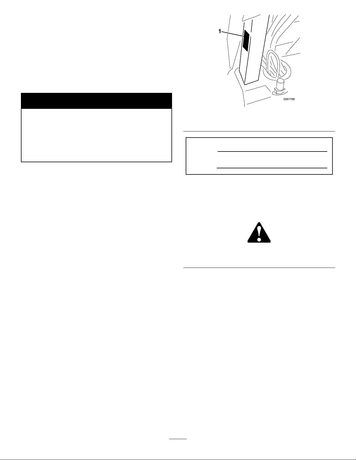
104-7628
1.ReadtheOperator’sManual.
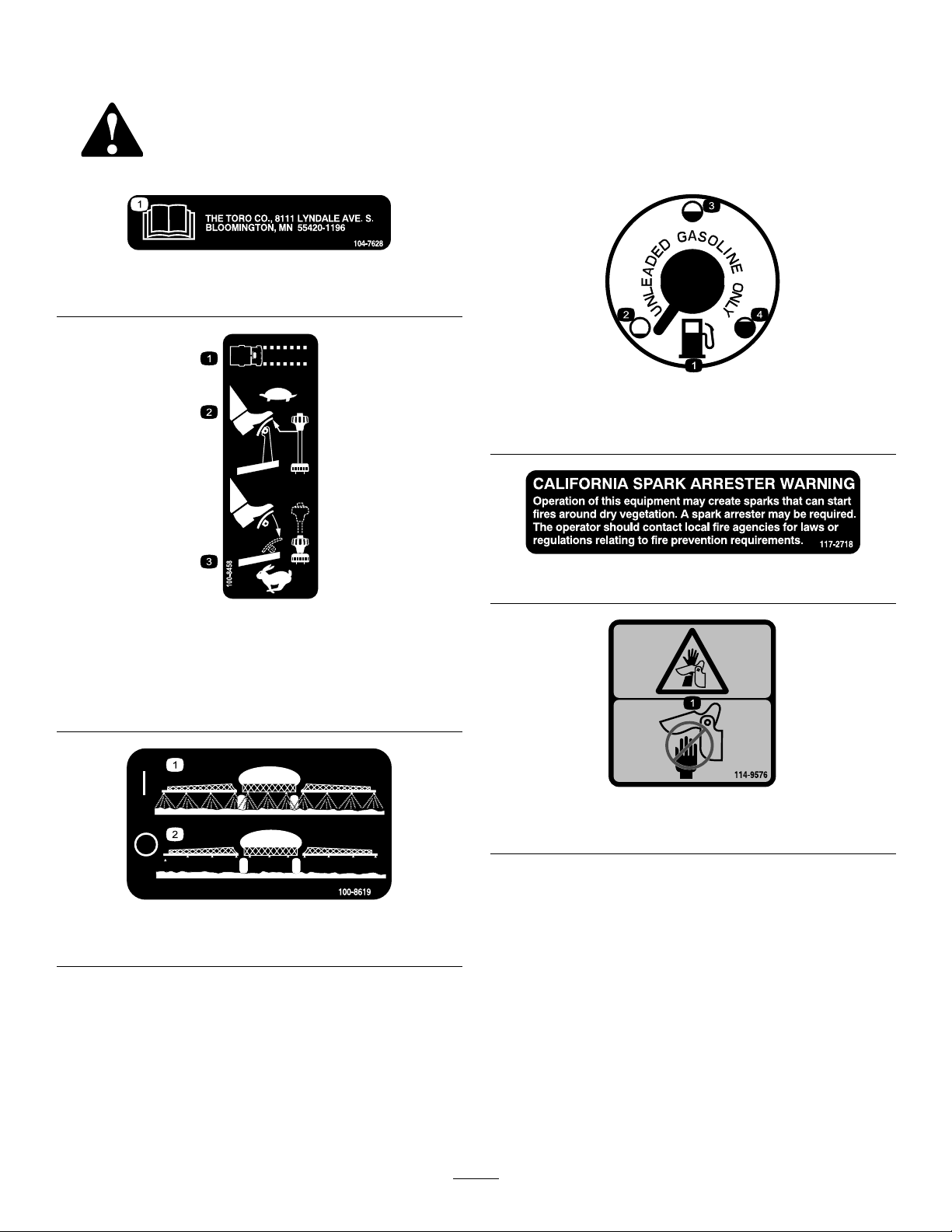
100-8386
1.Fuel
2.Empty4.Full
3.Half-full
100-8458
1.Machinespeed
2.Tosetthemachinetoaslowspeed,reducepressureonthe
acceleratorandpulluponthespeedlimiter.
3.Tosetthemachinetoafastspeed,presstheaccelerator
pedalandpushdownonthespeedlimiter.
100-8619
1.Sprayon2.Sprayoff
117–2718
114-9576
1.Pinchpoint,hand—keephandawayfromhinge.
8
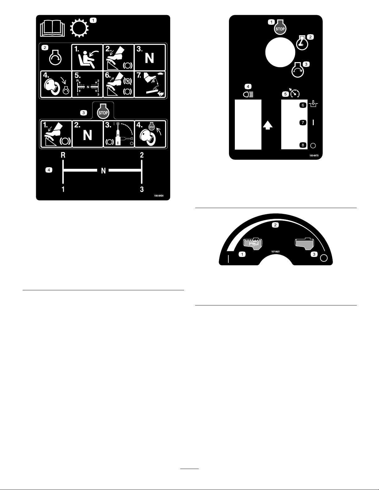
100-8454
1.ReadtheOperator’sManualforinformationonthe
transmission.
2.Tostarttheengine,sitontheoperator’sseat,pressthe
brake,settherangeselectortoNeutral,turntheignition
keytoEngine-start,settherangeselectortothedesired
gear,releasethebrakeandparkingbrake,andpressthe
acceleratorpedaltothedesiredspeed.
3.Tostoptheengine,pressthebrake,settherangeselector
toNeutral,settheparkingbrake,andturntheignitionkey
toEngine-stop.
4.Rangeselectorgearpattern
100-8470
1.Engine—stop5.Neutralenginespeedlock
2.Engine—run6.Engage
3.Engine—start
4.Headlights
7.On
8.Off
107-8621
1.Agitationon
2.Continuousvariable
setting
3.Agitationoff
9
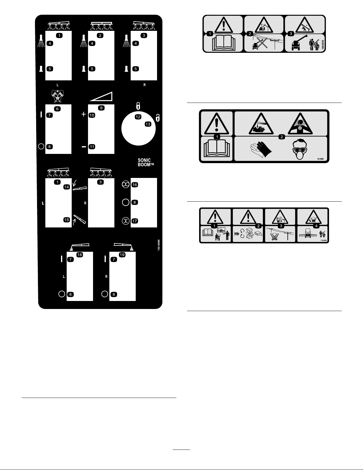
106-5016
1.Warning—readtheOperator’sManual.
2.Electricshockhazard,overheadpowerlines—stayaway
fromoverheadpowerlines.
3.Crushinghazard,boom—keepbystandersasafedistance
fromthemachine.
93-0688
1.Warning—readtheOperator’sManual.
2.Causticliquid/chemicalburnandtoxicgasinhalation
hazards—wearhand,skin,eye,andrespiratoryprotection.
100-8489
1.Leftboom
2.Centerboom
3.Rightboom13.Unlocked
4.Sprayon
5.Sprayoff
6.Pump16.Automatic
7.On
8.Off18.Leftboomfoammarker
9.Continuousvariable
setting,spraypressure
10.Increase
11.Decrease
12.Locked
14.Lowertheboom.
15.Raisetheboom.
17.Manual
19.Rightboomfoammarker
110-5240
1.Warning—readtheOperator’sManualandreceivetraining
beforeoperating.
2.Warning—stayawayfrommovingparts,donotoperate
withcoversremoved.
3.Electricshockhazard,overheadpowerlines—stayaway
fromoverheadpowerlines.
4.Crushinghazard,boom—keepbystandersasafedistance
fromthemachine.
10

110-5143
1.Warning—readtheOperator’sManual.
2.TippingHazard—driveslowlyoverroughterrainandwhen
turning.
3.Fallingandarm/leginjuryhazards—donotcarrypassengers
andkeeparmsandlegsinsideofthevehicleatalltimes.
4.Tostoptheengine,pressthebrake,movetherange
selectortoNeutral,settheparkingbrake,releasethebrake
pedal,turntheignitionkeytoEngine-stop,andremovethe
key.
106-5051
1.Warning—readtheOperator’sManual;usefresh,clean
waterforrst-aidwashing.
108-3307
107-8640
1.Warning—readtheOperator’sManual;usefresh,clean
waterforrinsingthetank.
106-1355
1.Warning—donotenterthetank.
1.Totalarea8.Width
2.Boomselect9.Distance
3.Speed10.Speedcalibration
4.Unitsofmeasure11.Subvolume
5.Selectunits
6.Applicationrate13.Flowmetercalibration
7.Subarea
11
108-3309
12.Totalvolume
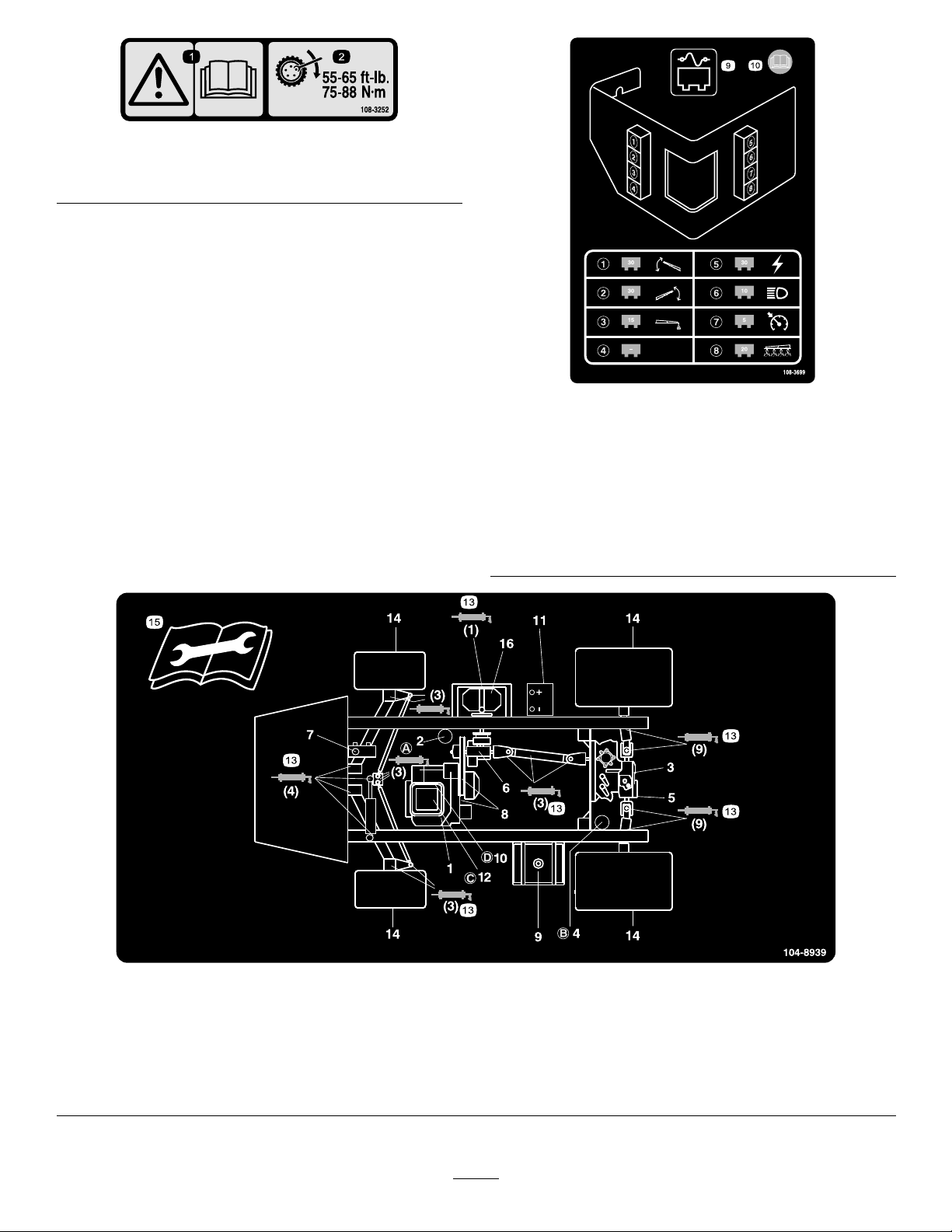
1.Warning—readthe
Operator’sManual.
108-3252
2.Torquelugnutsto55-65
ft-lb(75-88N·m).
108-3699
1.30ampfuse,leftboom
actuator
2.30ampfuse,rightboom
actuator
3.15ampfuse,foammarker8.20ampfuse,spraysystem
4.Empty9.Fusepanel
5.30ampfuse,power10.ReadtheOperator’s
6.10ampfuse,headlights
7.5ampfuse,cruisecontrol
Manualformore
information.
104-8939
1.Engineoillevel(dipstick)
2.Engineoillter6.Gearboxuidlevel10.Fuellter
3.Transaxle/hydraulicuid
level(dipstick)
4.Transaxlehydrauliclter
5.Hydraulicstrainer9.Fuel,unleadedonly
7.Brakeuid
8.Belts,steeringanddrive12.Aircleaner16.Pump
11.Battery15.Readtheinstructions
12
13.Grease
14.Tirepressure
beforeservicingor
performingmaintenance.

Setup
LooseParts
Usethechartbelowtoverifythatallpartshavebeenshipped.
ProcedureDescription
1
2
3
4
5
90degreetting
Quickcoupler
Hoseadapter1
Fillreceptaclebracket1
Flange-headbolt,5/16x3/4inch
Anti-siphonhose1
SprayProMonitor
SprayProDecal
Bracket1
Flange-headbolt,3/4inch
Flangenut,1/4inch
Knob2
Washer2
Carriagebolt
Nopartsrequired
Nopartsrequired
Ignitionkey1
Operator’sManual
EngineOperator’sManual
PartsCatalog
OperatorTrainingMaterial
RegistrationCard
Pre-deliveryInspectionSheet
Qty.
Use
1
1
Installtheanti-siphonllreceptacle.
1
1
1
2
2
2
–
–
1
1
1
1
1
1
InstalltheSpray-Promonitor.
Checktheboomhingesprings.
Adjusttheboomstolevel.
Readthemanualsandviewthetraining
materialbeforeoperatingthemachine.
Note:Determinetheleftandrightsidesofthemachine
fromthenormaloperatingposition.
13

1
InstallingtheAnti-siphonFill
Receptacle
Partsneededforthisprocedure:
1
90degreetting
1
Quickcoupler
1Hoseadapter
1Fillreceptaclebracket
1
Flange-headbolt,5/16x3/4inch
1Anti-siphonhose
4.Locktheadapterintoplacebyswingingthelevers
towardtheadapterandthensecurethemwiththe
hairpincotters(Figure3).
5.Installtheanti-siphonhosethroughthelarge
openingonthebracketandontothebarbedendof
the90degreeelbowtting(
Important:Donotlengthenthehosetoallow
contactwiththetankuids.
Figure3).
2
InstallingtheSprayPro
Monitor
Procedure
1.Placethellreceptaclebracketoverthethreaded
holeinthetankandsecureitwithaange-headbolt
(5/16x3/4inch)(Figure3).
Figure3
1.Fillreceptaclebracket
2.Threadedholeinthetank6.Hoseadapter
3.Flangebolt,5/16x3/4inch
4.90degreeelbowtting
5.Quickcoupler
7.Anti-siphonhose
Partsneededforthisprocedure:
1
SprayProMonitor
1
SprayProDecal
1Bracket
2
Flange-headbolt,3/4inch
2
Flangenut,1/4inch
2Knob
2Washer
2
Carriagebolt
Procedure
1.InstalltheSprayProDecaltothemonitor(Figure4).
2.Placethethreadedendofthe90degreeelbowtting
throughthebracketandthreadthequickcoupler
ontoit,securingittothebracket(Figure3).
Note:Installthettingwiththeopenendpointing
towardthelargeopeninginthebracketandtoward
thetankopeningsothewaterwillarcintothetank
whenyoullit.
3.Installthehoseadapterintothequickcoupler
(
Figure3).
Figure4
1.Spraypromonitor3.Decal,Lowerhalf
2.Decal,Upperhalf
Note:Besuretoorientthedecalasshownin
Figure20.
2.Installthemonitorbracketonthedash(
using2ange-headbolts(1/4x3/4inch)and2
angenuts(1/4inch).
14
Figure5)

Figure5
1.SprayPromonitor
2.Bracket4.Knob
3.Looselyinstallthe2carriagebolts,rubber
washers,andknobsonthebracketasillustratedin
FigureFigure5andFigure6.
3.Flange-headbolts,
1/4x3/4inch
1.Connectorsfromthe
sprayer
3
Figure7
2.Connectorsfromthe
monitor
Note:Installthecarriageboltsandrubberwashers
insideofthebracketandtheknobsontheoutside.
Figure6
1.Carriagebolt
2.Rubberwasher4.Bracket
4.Removethelargegrommetfromtheholeinthedash
andthreadthecablesonthemonitorthroughthe
grommetandthedash.
5.Installthegrommetintothedash.
6.InstalltheSprayPromonitoroverthecarriagebolt
heads(Figure5)andtightentheknobstosecureit.
7.ConnecttheSprayProwireconnectorstothewire
connectorslocatedunderthedash(Figure7).
3.Knob
CheckingtheBoomHinge
Springs
NoPartsRequired
Procedure
Important:Operatingthespraysystemwith
theboomhingespringsundertheincorrect
compressioncoulddamagetheboomassembly .
Measurethespringsandusethejamnutto
compressthespringsto1.56inchesifnecessary.
Thesprayerisshippedwiththeboomextensionsswung
forwardtofacilitatepackagingofthemachine.The
springsarenotfullytightenedatthetimeofmanufacture
toallowtheboomstobeinthispositionfortransit.
Beforeoperatingthemachine,thespringsmustbe
adjustedtothecorrectcompression.
1.Ifnecessary,removethepackingcomponentsthat
securetherightandleftextensionboomsduring
shipping.
2.Supporttheboomswhiletheyareextendedtothe
sprayposition.
3.Attheboomhinge,measurethecompressionofthe
upperandlowerspringswhiletheboomsareintheir
extendedposition(
A.Allspringsmustbecompresseduntilthey
measure1.56inches.
Figure8).
15
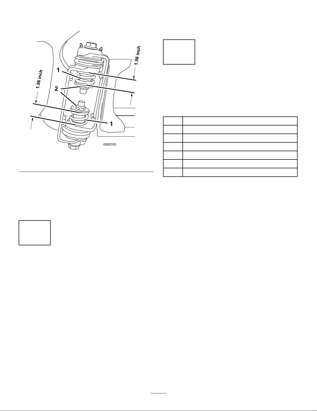
B.Usethejamnuttocompressanyspringthat
measuregreaterthan1.56inches.
Figure8
1.Boomhingespring2.Jamnut
4.Repeattheprocedureforeachspringonbothboom
hinges.
5.Movetheboomsintothetransport“X”position.
SeeOperatingtheBoomsintheOperationsection
formoreinformation.
Note:Thebumpermayexperiencesomecompression
overtime.Iftheboomsdropbelowlevel,usethis
proceduretoreadjustthebumperpositionneeded.
5
CompletingtheSetup:
Learningmoreaboutyour
product.
Partsneededforthisprocedure:
1Ignitionkey
1
Operator’sManual
1
EngineOperator’sManual
1
PartsCatalog
1
OperatorTrainingMaterial
1
RegistrationCard
1
Pre-deliveryInspectionSheet
Procedure
1.Readthemanuals.
2.ViewtheOperatortrainingmaterial.
4
AdjustingtheBoomstoLevel
NoPartsRequired
Procedure
1.Attheoperator’ sposition,turntheignitionkeyto
Ontoenergizethesystem.
2.Movetheboomsintopositionsothattheyarelevel
withtheground.
3.Removethekeyandexittheoperator’sposition.
4.Atthehinge,adjustthepositionofthebumpersso
theboomcannotmovepastlevelwiththeground.
Takecaretomakesurethebumperislevel.
5.Tightentheboltandnuttolockthebumpersintothe
adjustedposition.T orquethefastenersto135-165
ft-lbs(183-223N-m).
3.CompletetheregistrationcardandreturntoToro.
4.Storethedocumentationinasafeplace.
16
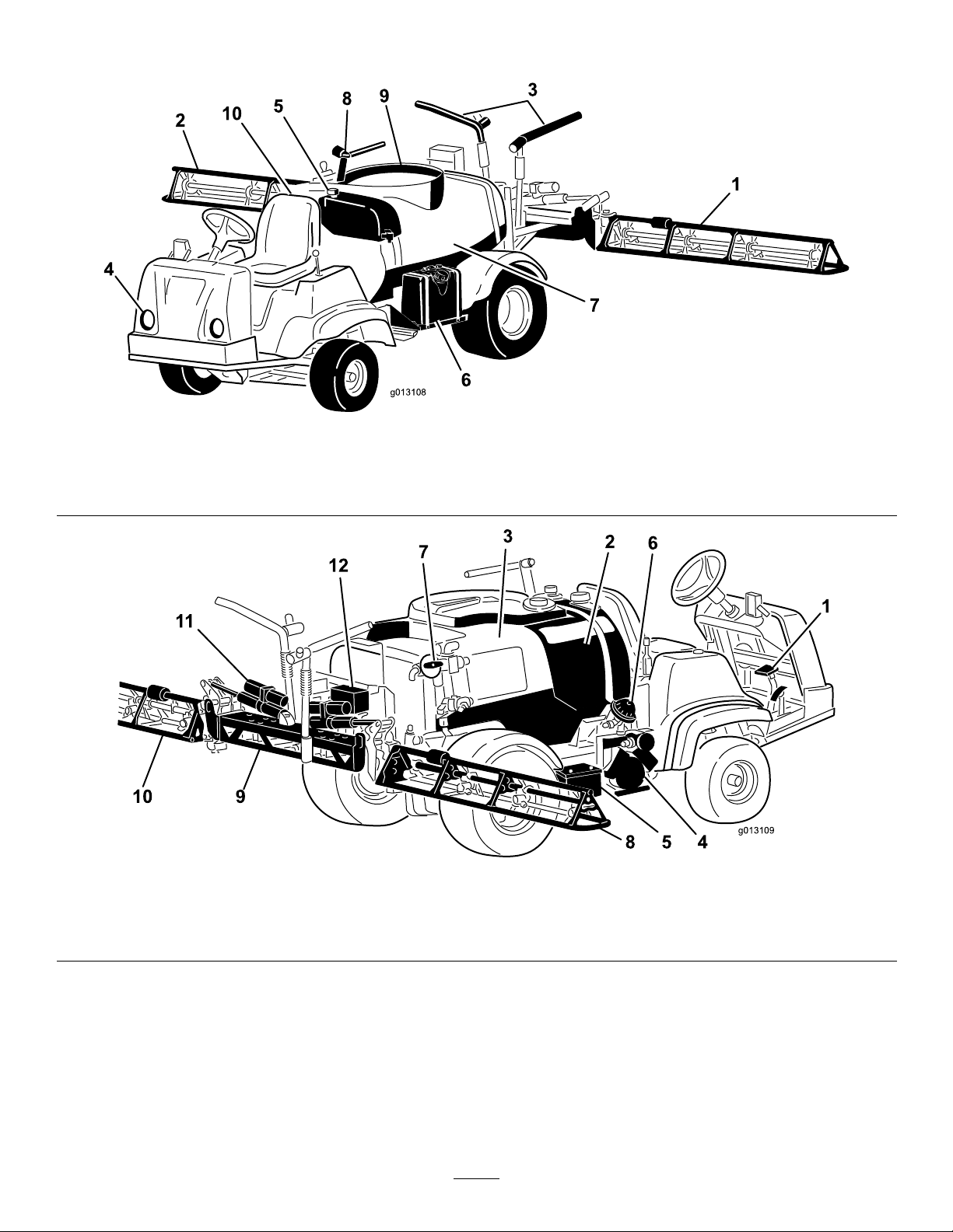
ProductOverview
g013108
g013109
Figure9
1.Leftboom
2.Rightboom5.Freshwatertank
3.Boomtransportcable6.Fueltank9.Tanklid
4.Headlight
7.Chemicaltank10.Operator’sposition
8.Anti-SiphonReceptacle
Figure10
1.Pedals4.Pump7.Agitationcontrolvalve
2.Rinsetank5.Battery8.Rightboom11.Boomcontrolcylinder
3.Chemicaltank
6.Pumppressuredampener
17
9.Centerboom
10.Leftboom
12.Valvecluster
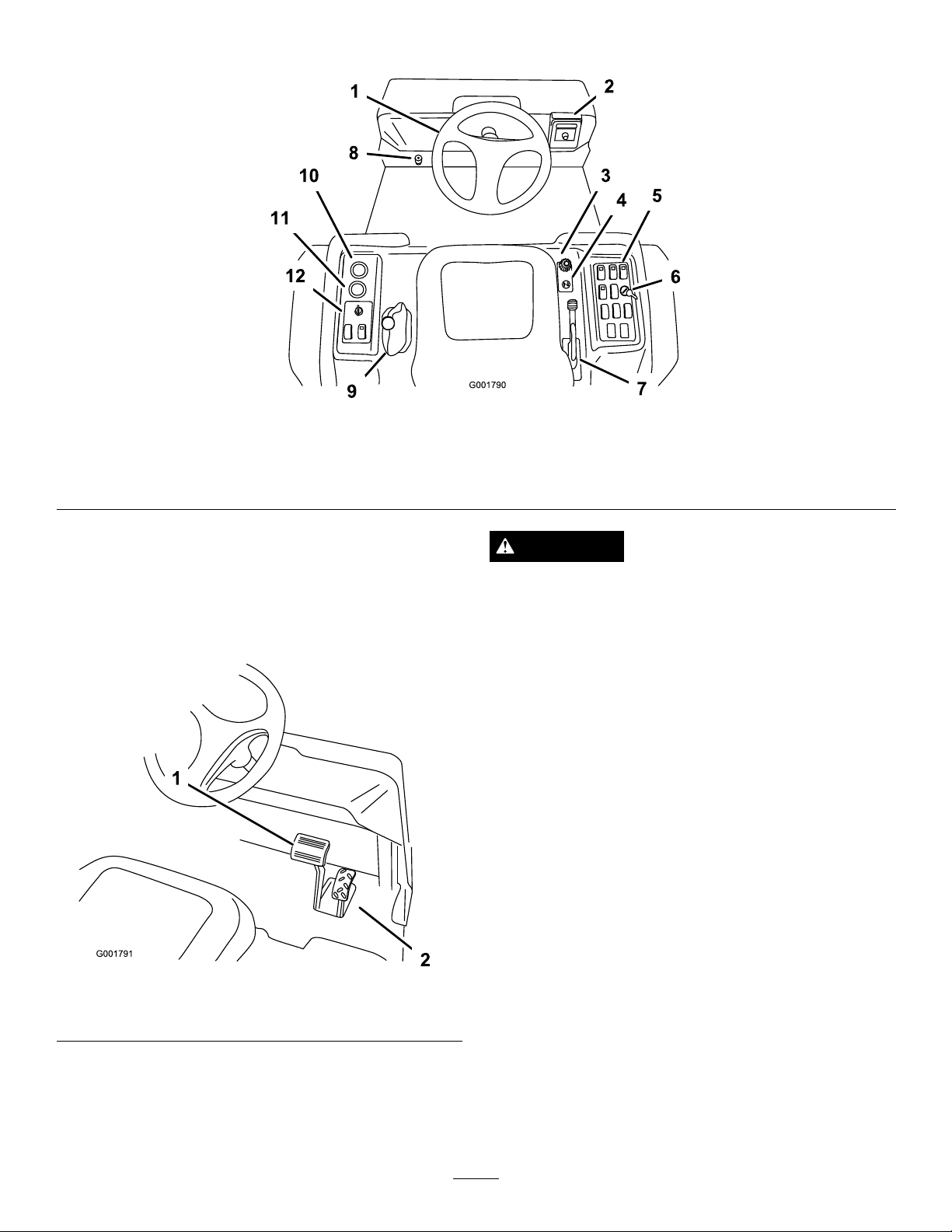
Controls
Figure11
1.Steeringwheel4.Choke
2.Spray-Promonitor5.Sprayercontrols8.Masterboomfootswitch
3.Speedlimiter
6.Ratelockoutswitch
7.Parkingbrake10.Voltmeter
9.RangeSelector
11.Hourmeter
12.Vehiclecontrols
AcceleratorPedal
Theacceleratorpedal(Figure12)givesyoutheabilityto
varygroundspeedofthesprayer.Pressingthepedal
increasesgroundspeed.Releasingthepedalwillslow
thesprayerandtheenginewillidle.
Figure12
1.Brakepedal2.Acceleratorpedal
CAUTION
Brakescanbecomewornorcanbeadjusted
incorrectlyresultinginpersonalinjury .
Ifbrakepedaltravelstowithin1inch(2.5cm)ofthe
sprayeroorboard,thebrakesmustbeadjusted
orrepaired.
ParkingBrake
Theparkingbrakeisalargelevertotherightoftheseat.
(Figure13).Engagetheparkingbrakewheneveryou
planonleavingtheseattopreventaccidentalmovement
ofthesprayer.Toengagetheparkingbrake,pullupand
backonthelever.Todisengage,pushitforwardand
down.Ifthesprayerisparkedonasteepgrade,apply
theparkingbrakeandplaceblocksatthedownhillside
ofthewheels.
BrakePedal
Usethebrakepedaltostoporslowthesprayer
(Figure12).
18
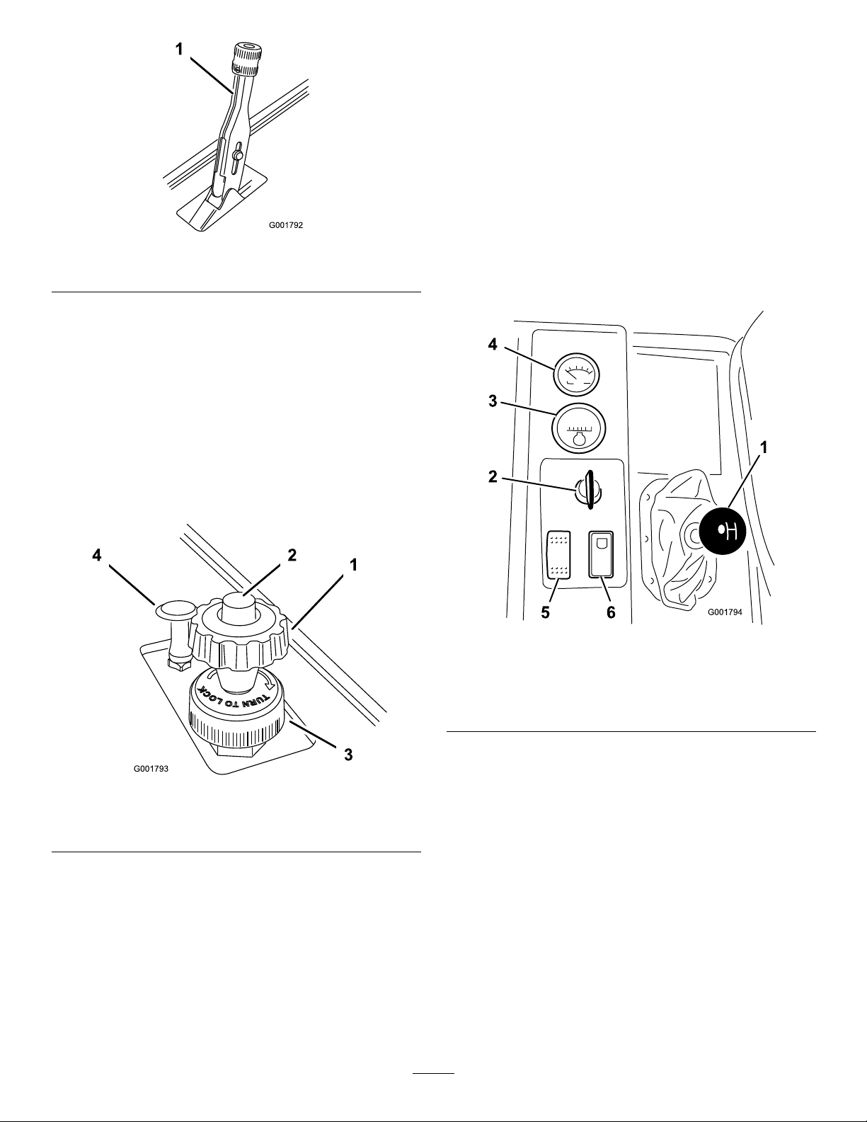
Figure13
1.Parkingbrakelever
SpeedLimiter
Thespeedlimiterisalargeknoblocatedtotherightof
theseat(Figure14).Itallowsyoutosetthemaximum
downwardtraveloftheacceleratorpedal,thereby
limitingthemaximumrpmoftheengine.Thisindirectly
limitsthespeedofthesprayer.
RangeSelector
Therangeselector,locatedtotheleftoftheseat,has
5positions:3forwardspeeds,Neutral,andReverse
Figure15).Theenginewillstartonlywhentherange
(
selectorisintheNeutralposition.Youmustalsofully
pressthebrakewiththesprayerstoppedtochange
ranges.
Important:Donotshiftoutoforchangeranges
whilethevehicleismoving.Attemptingtochange
rangeswhilethevehicleismovingcandamagethe
transmission.Onlystoppingthesprayercompletely,
andfullyengagingthebrakewillsafelydisengage
thelockingpinandallowtherangestobechanged.
Note:Thevehiclecontrolstheapplicationratebased
onyourspeedandyoudonotneedtokeepaconstant
speedtoapplyataconstantrate.
Figure14
1.Speedlimiterknob
2.Speedlimiterbutton4.Chokecontrol
3.Lockingring
ChokeControl
Figure15
1.RangeSelector
2.Ignitionswitch5.Headlightswitch
3.Hourmeter6.Neutralenginespeedlock
4.Voltmeter
switch
IgnitionSwitch
Theignitionswitch(Figure15),usedtostartandstop
theengine,has3positions:Stop,Run,andStart.Rotate
thekeyclockwisetotheStartpositiontostarttheengine
andreleaseittotheRunpositionwhenstarted.Rotate
thekeytotheStoppositiontostoptheengine.
Thechokecontrolisasmallknobtotherightofthe
seat.(Figure14).Tostartacoldengine,pullthechoke
controlup.Aftertheenginestarts,regulatethechoketo
keeptheenginerunningsmoothly.Assoonaspossible,
pushthecontroldowntotheOffposition.Awarm
enginerequireslittleornochoking.
HourMeter
Thehourmeter(Figure15)indicatesthetotalnumber
ofhourstheenginehasrun.Thehourmeterstartsto
functionwheneverthekeyisturnedtotheRunposition.
19
Voltmeter
BoomSwitches
Thevoltmeter(Figure15)indicatesthelevelofcharge
inthebattery.Whenthebatteryisfullycharged,the
voltmeterwillreadinthecenterofthedialwhenthe
keyisintheRunpositionwiththeengineoff.When
theengineisrunningthevoltmeterneedleshouldbe
totheright.
HeadlightSwitch
Toggletheswitchtooperatetheheadlights(Figure15).
Pushitforwardtoturnthelightsonandrearwardto
turnthemoff.
NeutralEngineSpeedLockSwitch
WhentherangeselectorisintheNeutralposition,you
canusetheacceleratorpedaltospeeduptheengine,
thenpushthisswitchforwardtosettheengineatthat
speed.Thisisnecessarytorunthechemicalagitation
whilestationaryoroperatingattachmentssuchasthe
handsprayer(
Important:Therangeselectormustbeinthe
neutralpositionfortheswitchtowork.
Figure15).
Theboomswitchesarelocatedatthefrontofthe
controlpaneltotherightoftheseat(
Figure17).Toggle
eachswitchforwardtoturnthecorrespondingboom
sectiononandrearwardtoturnthemoff.Whenthe
switchisturnedon,alightontheswitchilluminates.
Theseswitcheswillonlyaffectthespraysystemwhen
themasterboomswitchison.
FuelGauge
Thefuelgaugeislocatedontopofthefueltank,on
therightsideofthemachineandshowstheamountof
fuelinthetank.
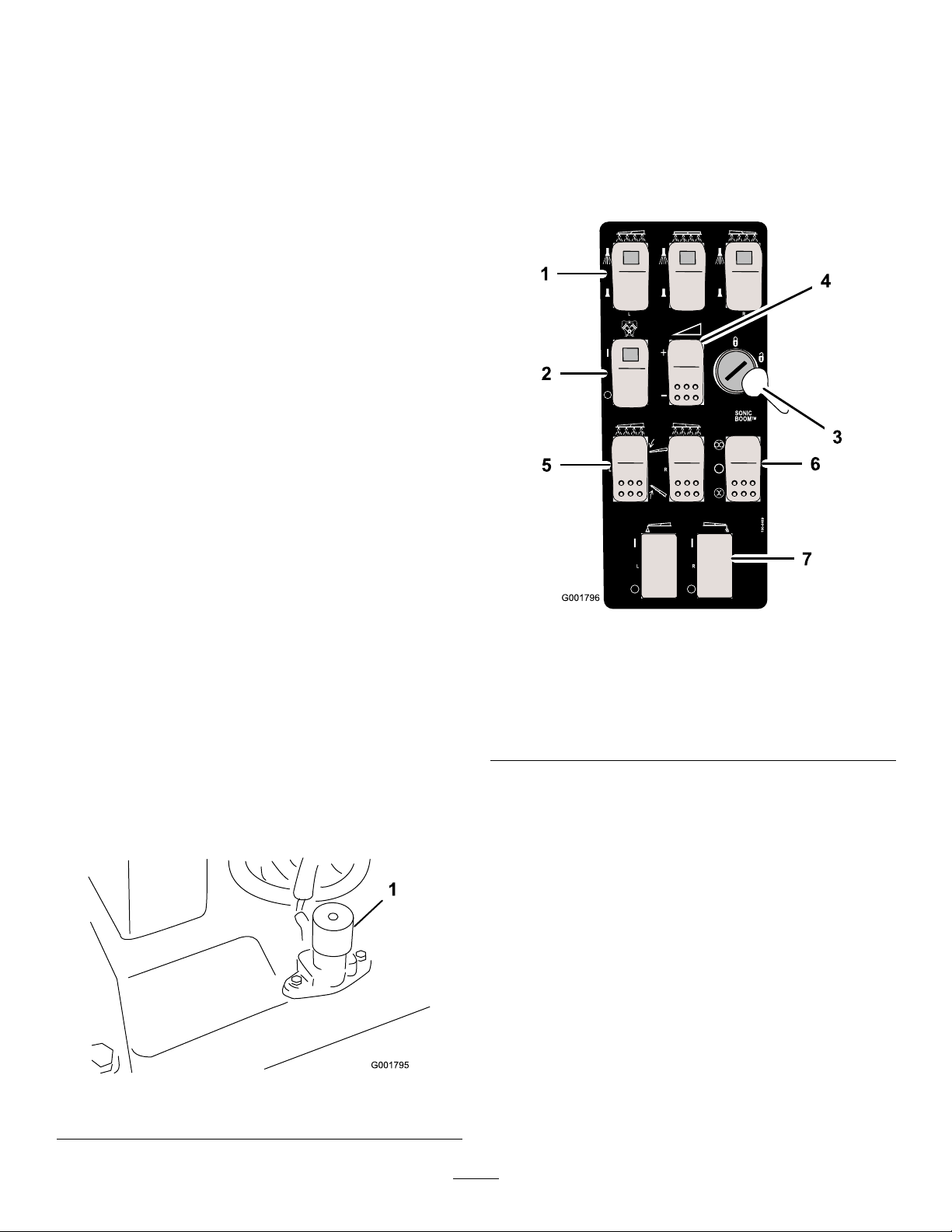
MasterBoomSwitch
Themasterboomswitchislocatedontheoorboard
ofthemachinecabandtotheleftoftheoperator.It
allowsyoutostartorstopthesprayoperation.Press
theswitchwithyourfoottoenableordisablethespray
system(
SprayPromonitorscreenreads“Hold."
Figure16).Whenthemasterswitchisoff,the
Figure17
1.Boomswitches,left,right
andcenter
2.Pumpswitch
3.Ratelockoutkey
4.Applicationrateswitch
5.Boomliftswitch,leftand
right
6.Sonicboomswitch
7.Foammarkerswitch,left
andright
PumpSwitch
Thepumpswitchislocatedonthecontrolpaneltothe
rightoftheseat(Figure17).T ogglethisswitchforward
torunthepumporrearwardtostopthepump.
Important:Onlyengagethepumpswitchwhen
theengineisatlowidletoavoiddamagingthe
pumpdrive.
ApplicationRateSwitch
1.Masterboomswitch
Figure16
Theapplicationrateswitchislocatedonthecontrol
paneltotherightoftheseat(Figure17).Pressandhold
theswitchforwardtoincreasethespraysystempressure,
orpressandholditrearwardtodecreasepressure.
20

RateLockoutKeySwitch
G0131 13
1 2
3
Theratelockoutkeyswitchislocatedonthecontrol
paneltotherightoftheseat(
Figure17).Turnthekey
counterclockwisetothelockedpositiontodisablethe
applicationrateswitch,therebykeepinganyonefrom
accidentallychangingtheapplicationrate.Turnthe
keyclockwisetotheunlockedpositiontoenablethe
applicationrateswitch.
Important:Donotattempttomovetherange
selectorwhiletheratelockoutkeyisengaged.
Forcingtheselectorwhilemovingwilldamage
lockoutkeycomponents.
BoomLift
Theboomliftswitchesareusedtoraisetheleftand
rightboomrespectively .
1.Regulating(ratecontrol)
valve
2.Flowmeter
Flowmeter
Figure18
3.Boomvalves
SonicBoom(Optional)
TheSonicBoomswitchisarockerswitchusedto
operatetheSonicBoom.Toggleswitchforwardfor
automatic,rearwardformanualandcenterforOff.
FoamMarkerSwitchLocations
(Optional)
Ifyouinstalltheelectricboomlift,sonicboom,and
foammarkerkit,youwilladdswitchestothecontrol
panelforcontrollingtheiroperation.Thesprayercomes
withplasticplugsintheselocations.
Regulating(RateControl)Valve
Thisvalve,locatedbehindthetank(Figure18),controls
theamountofuidthatisroutedtotheboomsby
directinguidowtotheboomsorthebypasshose
totheagitationvalve.
Theowmetermeasurestheowrateoftheuidfor
usebytheSprayPro™system(Figure18).
BoomValves
Thesevalvesturnthethreeboomsonoroff(Figure18).
Ifyoudonothaveaboominstalledordonotwant
aboomtobeabletobeturnedon,youcanmanually
operateeachvalvebydisconnectingthewireconnector
inthevalve,thenrotatetheknobonthevalveclockwise
toturnthevalveofforcounterclockwisetoturniton.
BoomBypassValves
Theboombypassvalvesredirecttheuidowfora
boomtothetankwhenyouturnofftheboomsection.
Youcanadjustthesevalvestoensurethattheboom
pressureremainsconstantnomatterhowmanybooms
areon.RefertoCalibratingtheBoomBypassValves,
intheOperationsection.
AgitationControlValve
Thisvalveislocatedontherightsideofthetank
(Figure19).Turntheknobonthevalvetothe9o’clock
positiontoturnonthetankagitationandtothe3
o’clockpositiontoturnoffthetankagitation.
21
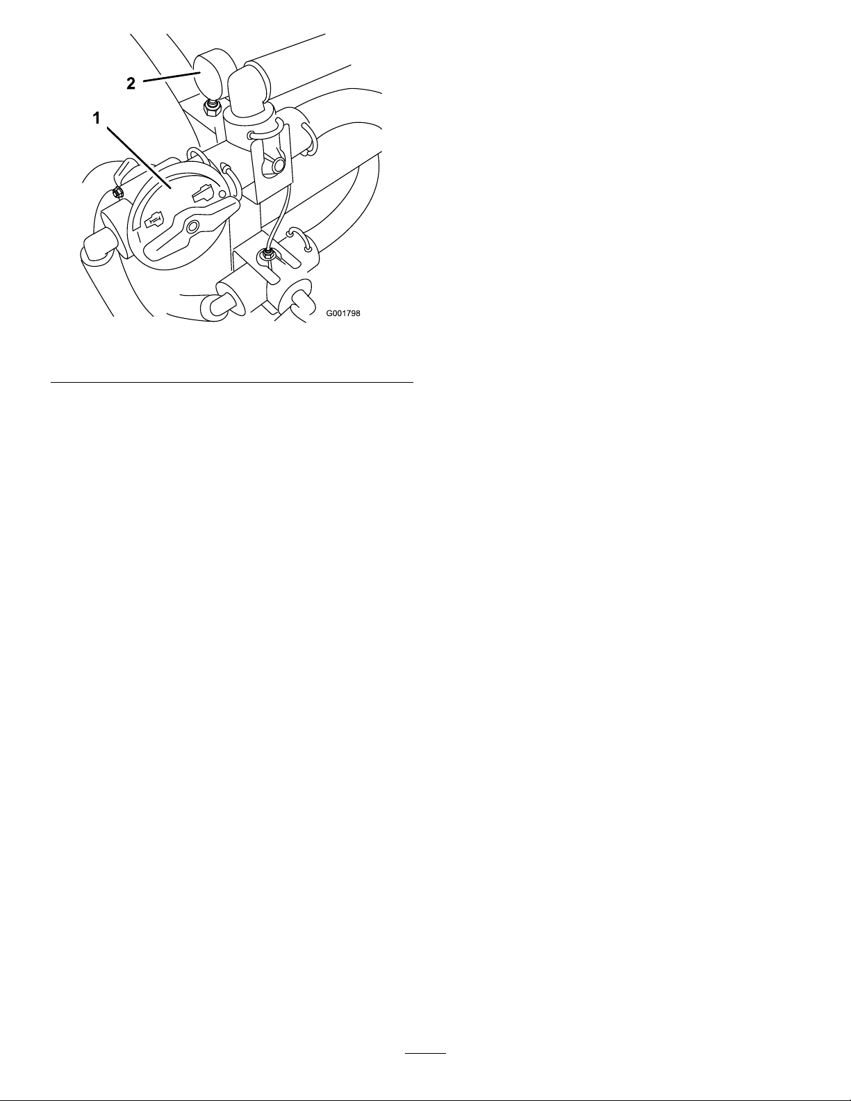
PressureGauge
Thepressuregaugeislocatedtotherightofthetank
Figure19).Thisgaugeshowsthepressureoftheuid
(
inthesysteminpsiandkPa.Usethegaugetoadjustthe
by-passvalveswheneveryouchangenozzles.
Anti-siphonFillReceptacle
Tothefrontofthetankcoverisahosereceptaclewitha
threadedtting,a90degreebarbedtting,andashort
hosewhichyoucandirecttowardthetankopening.This
receptacleallowsyoutoconnectawaterhosetoitand
llthetankwithwaterwithoutcontaminatingthehose
withthechemicalsinthetank.
Figure19
1.Agitationcontrolvalve2.Pressuregauge
Note:Foragitationtowork,thepumpmustbeon
andtheenginemustberunningaboveanidle.Ifyou
stopthesprayerandneedagitationon,placetherange
selectorintheNeutralposition,settheparkingbrake,
presstheacceleratorpedaltotheoor,turnthepump
OnandturntheneutralenginespeedlockOn.
Important:Donotlengthenthehosetoallow
contactwiththetankuids.
22
 Loading...