

Toro 41086, Multi-Pro 5700-D, Multi-Pro 5600 Operator's Manual

ProControlSpraySystem
FormNo.3365-343RevA
Multi-Pro
ModelNo.41086—SerialNo.310000001andUp
®
5600and5700-DTurfSprayer
ToregisteryourproductordownloadanOperator'sManualorPartsCatalogatnocharge,gotowww.T oro.com.OriginalInstructions(EN)
Thisattachmentcontrolsthesprayfunctionsofaturf
G013320
1
sprayerbasedoncalculationfromuserinputandis
intendedtobeusedbyprofessional,hiredoperatorsin
commercialapplications.Itisprimarilydesignedfor
sprayinggolfcourseapplications,parks,sportselds,
andoncommercialgrounds.Itisdesignedtoonlybe
usedinconjunctionwithmachinesdesignatedbythe
manufacturer.
ThisproductcomplieswithallrelevantEuropean
directives,fordetailspleaseseetheseparateproduct
specicDeclarationofConformity(DOC)sheet.
Figure2
1.Safetyalertsymbol.
Thismanualusestwootherwordstohighlight
information.Importantcallsattentiontospecial
mechanicalinformationandNoteemphasizesgeneral
informationworthyofspecialattention.
Introduction
Readthismanualcarefullytolearnhowtooperateand
maintainyourproductproperly.Theinformationinthis
manualcanhelpyouandothersavoidinjuryandproduct
damage.AlthoughTorodesignsandproducessafe
products,youareresponsibleforoperatingtheproduct
properlyandsafely.YoumaycontactTorodirectlyat
www.Toro.comforproductandaccessoryinformation,
helpndingadealer,ortoregisteryourproduct.
Wheneveryouneedservice,genuineToroparts,or
additionalinformation,contactanAuthorizedService
DealerorToroCustomerServiceandhavethemodel
andserialnumbersofyourproductready.
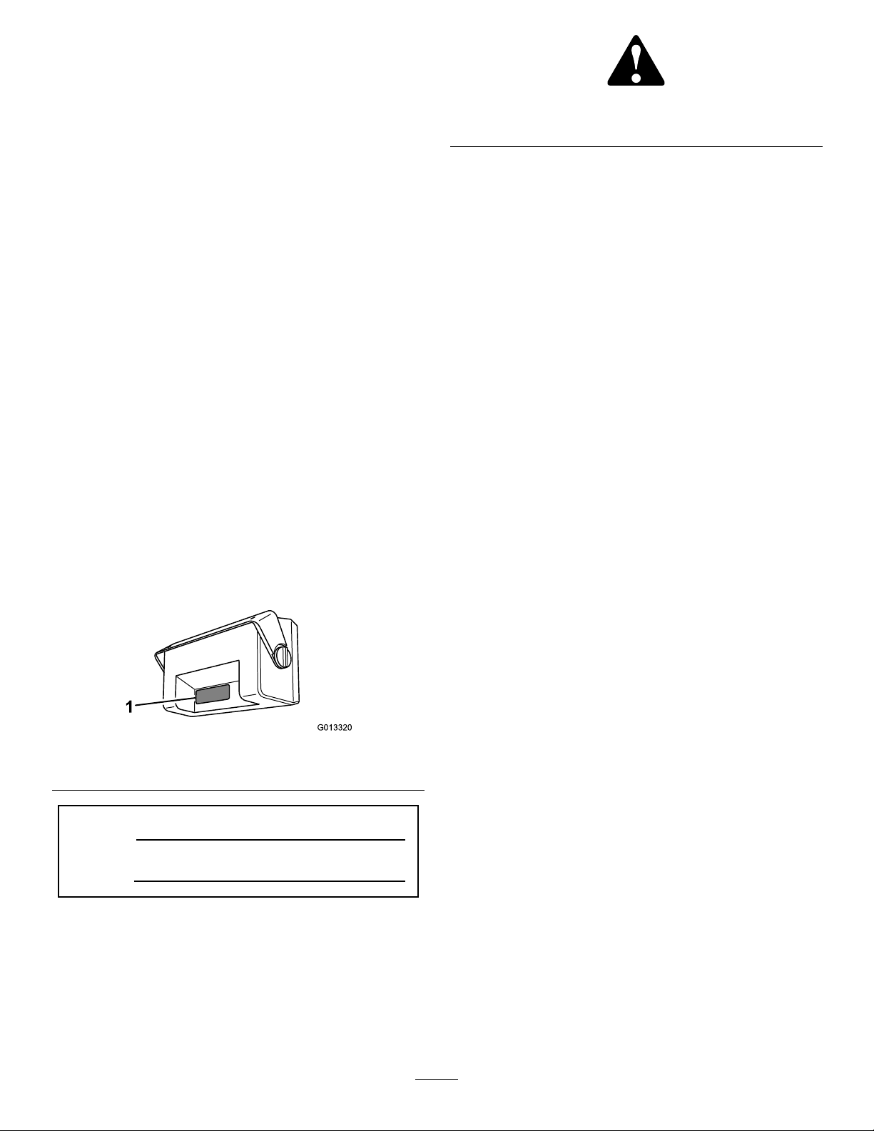
illustratesthelocationofthemodelandserialnumbers
ontheproduct.
Figure1
1.Locationofthemodelandserialnumbers
ModelNo.
SerialNo.
Figure1
Contents
Introduction.................................................................2
Safety...........................................................................3
Setup............................................................................4
InstallingtheProControlForModelYear2009
andOlderonly..................................................5
InstallingtheProControlForModelYear2010
andNeweronly.................................................6
ProductOverview........................................................9
Controls...............................................................9
Operation...................................................................11
InitiallyProgrammingtheConsole
Computer.......................................................11
ProgrammingtheConsoleComputer..................12
Self-TestingtheConsoleComputer.....................14
ActivatingtheDataLock....................................14
ChangingtheDataLock.....................................14
EnteringtheModeSequencewiththeData
LockActivated...............................................15
SettingthePowerDownDelayTime...................15
UsingtheConsoleComputerAlarm...................15
SettingtheLowLimitFlowSetPointandLow
LimitAlarm...................................................15
SettingUptheSystem.........................................15
InitiallyField-testingtheSystem..........................16
Maintenance...............................................................17
RecommendedMaintenanceSchedule(s)................17
CleaningtheFlowmeter......................................17
CalibratingtheFlowmeter..................................17
TestingtheFlowmeterCable...............................18
Troubleshooting.........................................................19
Thismanualidentiespotentialhazardsandhas
safetymessagesidentiedbythesafetyalertsymbol
(Figure2),whichsignalsahazardthatmaycauseserious
injuryordeathifyoudonotfollowtherecommended
precautions.
©2010—TheToro®Company
8111LyndaleAvenueSouth
Bloomington,MN55420
2
Contactusatwww.Toro.com.
PrintedintheUSA.
AllRightsReserved

Safety
Readandunderstandthecontentsofthismanual
beforeoperatingtheconsolecomputer.
•KeepthisdocumentwiththeOperator’sManualfor
theMultiPro
•Itisveryimportantthatallwhooperatethis
equipmenthavereadyaccesstotheseinstructions
atalltimes.
•Readtheseinstructionsandtheinstructionsinthe
Operator’sManualfortheMultiPro®5600or
5700-DTurfSprayercarefully .Befamiliarwiththe
controlsandtheproperuseoftheequipment.
•Neverallowchildrenorpeopleunfamiliarwiththese
instructionstousethecontrols.
•Neverspraywhilepeople,especiallychildren,orpets
arenearby.
•Chemicalscaninjurepeople,animals,plants,soils,
orotherproperty.Toavoidpersonalinjuryand
environmentaldamage:
®
5600or5700-DTurfSprayer.
–Selecttheproperchemicalsforthejob.
–Followthemanufacturer’sinstructionsonthe
chemicalcontainerlabels.Applyandhandle
chemicalsasrecommended.
–Handleandapplythechemicalswithcare.
–W earallnecessaryprotectiveequipment.
–Handlechemicalsinwell-ventilatedareas.
–Neversmokewhenhandlingchemicals.
–Properlydisposeofunusedchemicalsand
containers.
•Keepinmindthattheoperatororuserisresponsible
foraccidentsorhazardsoccurringtootherpeopleor
fordamagetoproperty.
3

Setup
LooseParts
Usethechartbelowtoverifythatallpartshavebeenshipped.
Description
Grommet,large
Carriagebolt(5/16x3/4inch)
Locknut(5/16inch)
Computerconsoleassembly
HandKnob2
Pivotbracket(2009andolderonly)
Hosebarbtting,90degree
Hose,long1
Hoseclamp
Screw,angehead(1/4x3/4inch)
Locknut(1/4inch)
Flowmeter1
Gasket
Flowmeterbarbtting,straight
Hoseclamp,wormscrew2
Hose,short1
Boomvalvecaps3
Plug1
O-ring,large
Grommet,large
Mountingbracket(2010andneweronly)
Carriagebolt(5/16x3/4inch)
Locknut(5/16inch)
Computerconsoleassembly
HandKnob2
Pivotbracket(2010andneweronly)
Hosebarbtting,90degree
Hose(49inlength)
Hoseclamp
Screw,angehead(1/4x3/4inch)
Locknut(1/4inch)
Flowmeter1
Gasket
Flowmeterbarbtting,straight
Hoseclamp,wormscrew2
Hose,(53inlength)
Boomvalvecaps3
Plug1
O-ring,large
Qty.
Use
1
2
2
1
1
1
5
2
2
2
2
1
1
1
4
4
1
1
1
1
5
2
2
2
2
1
1
InstalltheProControl(formodelyear2009andolderonly).
InstalltheProControl(formodelyear2010andnewer
only).
Note:Determinetheleftandrightsidesofthemachinefromthenormaloperatingposition.
Note:Duplicationsinthepartslististodistinguishneededpartsforthedifferentinstallationproceduresasthey
pertaintochangesinthemachinefrommodelyeartomodelyear.Usethepartslistforthemodelyearofthe
machinetargetedforinstallation.Surpluspartsmayremain.
4
CAUTION
G013301
3
4
5
2
4
1
4
5
G013302
2
6
1 6
3
4
5
50 in. (1.3 m)
27 in. (69 cm) 15 in. (38 cm)
To boom valves
To pump
G013303
1 2
Manychemicalsarehazardousandcancause
personalinjuryorenvironmentaldamageifyou
applythemimproperly.
Ensurethatsprayerhoseconnectionsaresecure
beforeoperatingthespraysystem.
7.Securethecablestotheconsolecomputerby
rotatingthelockingrings.
8.Attachtheconsolecomputertothemounting
bracketandsecureitwiththe2mountingknobs
Figure3).
(
MountingtheFlowmeter
InstallingtheProControl
ForModelYear2009andOlder
only.
InstallingtheConsoleComputer
1.Removetheknockoutpluginthedashboardand
insertthelargegrommet(
Figure3).
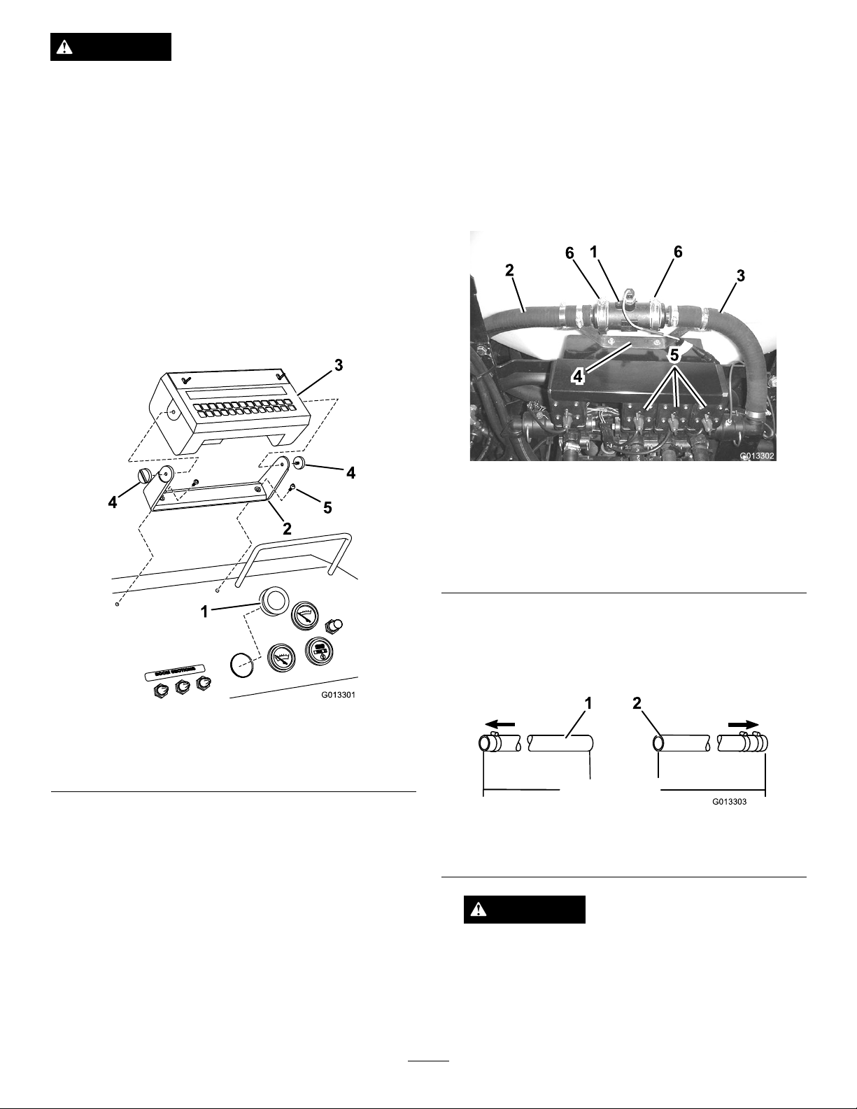
1.Disconnecttheboomsupplyhosettingfromthe
boomvalveassembly(Figure4).
Figure4
1.Flowmeter4.Flowmetermounting
2.Boomsupplyhose(longer
section)
3.Boomsupplyhose(shorter
section)
bracket
5.Boomvalveassembly
6.Wormgearscrewclamp
Figure3
1.Largegrommet4.Mountingknobs
2.Mountingbracket
3.Consolecomputer
5.Flangeheadscrew(2)
2.Removethemountingbracketfromtheconsole
computerandsecurethemountingbrackettothe
dashboardwith2angeheadscrews(
3.Cuttheplastictiethatsecurestheconsolecomputer
wiringharnessunderthedashboard.
4.Removethe2protectivecapsfromthecableends.
5.Inserttheconsolecontrolcableandspeedsensor
Figure3).
cablefromunderthedashboardthroughthehole
withthelargegrommet.
6.Plugthecablesintotheirproperreceptaclesinthe
rearoftheconsolecomputer.
2.Disconnecttheboomsupplyhosettingfromthe
teelocatedbehindtheboomvalveassembly .
3.Measure,mark,andcutthesupplyhoseasshown
inFigure5.
Figure5
1.Longersupplyhose
section
2.Shortersupplyhose
section
CAUTION
Manychemicalsarehazardousandcancause
personalinjuryorenvironmentaldamageifyou
applythemimproperly.
Ensurethatsprayerhoseconnectionsaresecure
beforeoperatingthespraysystem.
5
4.Installabarbedttingintotheendofthelonger
G013319
1
2
3
4
5
6
7
8
9
10
supplyhosesectionandsecureitwithahoseclamp
nexttothettingbody.
Important:Applyliquidsoaptothebarbed
ttingtolubricateit.Youmustinstallthe
hoseallthewayontothebarb.Donotuse
petroleum-basedlubricantssuchasgreaseor
oilbecausetheycandamagethehoseand
contaminatethesystem.
5.Attachthettingontheendofthelongersupply
hosesectiontothetee.
6.Attachthettingontheendoftheshortersupply
hosesectiontotheboomvalveassembly.
7.Attachtheowmeterbrackettotherearoftheboom
valvemountingbracketusing2angeheadscrews
(1/4in.)andangenuts.
8.Assemblethegasketsandbarbedttingsonthe
hosestotheowmeterusing2wormscrewclamps
Figure4).
Important:Notethedirectionoftheowon
thesideoftheowmeterandensurethatthe
owmeterisinstalledproperly(Figure4).
InstallingtheProControl
ForModelYear2010and
Neweronly.
InstallingtheConsoleComputer
1.Locateandremovetheknockoutpluginthe
dashboard.Installthelargegrommetintothe
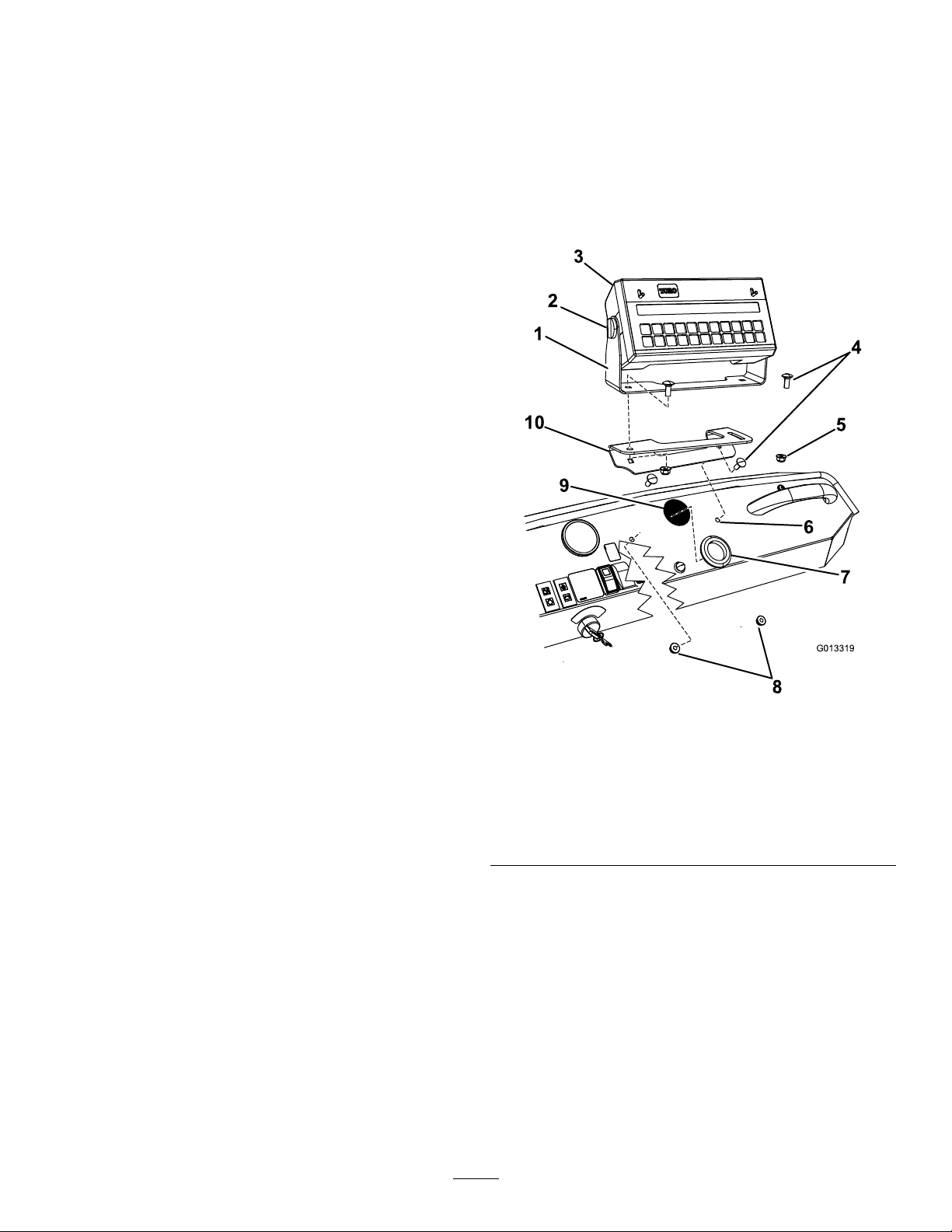
openinginthedash(Figure6).
9.Securetheowmetertothehoseswith2-inchworm
screwclamps.
10.Securethesupplyhosestotheowmetermounting
bracketwith2hoseclamps(
Figure4).
11.Installabarbedttingintotheendoftheshorter
supplyhosesectionandsecureitwithahoseclamp
nexttothettingbody.
12.Connecttheplugfromtheowmetertoitsmate
pluginthewiringharness.
ClosingtheBoomValves
Thissystemisdesignedtoworkwithadiaphragmpump
andmustoperatewiththeboombypassvalvesclosed.
Important:Beforeoperatingthespraysystemwith
theconsolecomputer,closeallbypassesonyour
boomvalvesbyturningintheredadjustmentknob
atthebottomoftheboomvalvesclockwiseasfar
aspossible.
Figure6
1.Pivotbracket(2010and
neweronly)
2.Handknob7.Largegrommet
3.Consolecomputer8.Locknut(5/16inch)
4.Carriagebolt(5/16x3/4
inch)
5.Locknut(5/16inch)
2.Locatethemountingbracketwiththecurvedslotin
6.Mountingholein
dashboard,existing
9.Knockedoutholeindash
10.Mountingbracket
looseparts.Installthebrackettothedashboardand
secureitwithtwocarriagebolts(5/16x3/4inch)
andtwolocknuts(5/16inch)asshownin
Figure6.
3.Locatetheround,multi-pinconsolecomputer
connectorsonthemainharnesssecuredtotheright
framememberunderthedashboard.
4.Cuttheplastictiethatsecurestheconsolecomputer
wiringtotheframeunderthedashboard.Remove
the2protectivecapsfromthecableends.
5.Routetheconsolecomputercablesfromunderthe
dashboardthroughtheholewiththelargegrommet.
6
 Loading...