

Page 1

PART NO. 12189SL
Service Manual
(Models 04043 and 04042)
Greensmaster
Preface
The purpose of this publication is to providetheservice
technician with information for troubleshooting, testing
and repairing assemblies and components on the
Greensmaster eFlex 1800 (Model 04043) and eFlex
2100 (Model 04042).
REFER TO THE OPERATOR’SMANUALFOROPERATING, MAINTENANCE AND ADJUSTMENT
INSTRUCTIONS.Spaceisprovided inChapter 2of this
booktoinserttheOperator’sManualandPartsCatalogs
for your machine. Replacement Operator’s Manuals
and Parts Catalogs are available on the internet at
www.toro.com
TheToroCompanyreserves therighttochange product
specifications or this publication without notice.
R
eFlex 1800/2100
This safety symbol means DANGER, WARNING
or CAUTION, PERSONAL SAFETY INSTRUCTION. When you see this symbol, carefully read
the instructions that follow. Failure to obey the
instructions may result in personal injury.
NOTE: A NOTE will givegeneral information aboutthe
correct operation, maintenance, service, testing or repair of the machine.
IMPORTANT: The IMPORTANT notice will give important in structions which must be followed to prevent damage to systems or components on the
machine.
E The Toro Company -- 2012
Page 2

This page is intentionally blank.
Greensmaster eFlex 1800/2100
Page 3

Table Of Contents
Chapter 1 -- Safety
General Safety Instructions 1 -- 2..................
Safety and Instruction Decals 1 -- 4................
Chapter 2 -- Product Records and Maintenance
Product Records 2 -- 1...........................
Maintenance 2 -- 1...............................
Equivalents and Conversions 2 -- 2................
Torque Specifications 2 -- 3.......................
Chapter 3 -- Traction and Reel Drive System
Specifications 3 -- 2..............................
General Information 3 -- 3........................
Special Tools 3 -- 6..............................
Adjustments 3 -- 8...............................
Service and Repairs 3 -- 11.......................
Chapter 4 -- Electrical System
General Information 4 -- 2........................
Electrical System Operation 4 -- 4.................
Lithium Battery Pack Charger Operation 4 -- 6......
Special Tools 4 -- 10.............................
Troubleshooting 4 -- 12...........................
InfoCenter Display 4 -- 16.........................
Adjustments 4 -- 22..............................
Component Testing 4 -- 26........................
Service and Repairs 4 -- 44.......................
Chapter 5 -- Chassis a nd Controls
Specifications 5 -- 2..............................
General Information 5 -- 3........................
Service and Repairs 5 -- 4........................
Chapter 6 -- Cutting Unit
Specifications 6 -- 3..............................
General Information 6 -- 4........................
Special Tools 6 -- 6..............................
Factors That Affect Quality Of Cut 6 -- 8............
Adjustments 6 -- 10..............................
Service and Repairs 6 -- 11.......................
Chapter 7 -- Groomer
Specifications 7 -- 2..............................
General Information 7 -- 3........................
Troubleshooting 7 -- 4............................
Adjustments 7 -- 6...............................
Service and Repairs 7 -- 7........................
Chapter 8 -- Foldout Drawings
Electrical Schematic 8 -- 3........................
Wire Harness Drawings 8 -- 4.....................
SafetyProduct Records
and Maintenance
Drive System
Traction and Reel
System
Electrical
Controls
Chassis andCutting Unit
Greensmaster eFlex 1800/2100
GroomerFoldout
Drawings
Page 4

This page is intentionally blank.
Greensmaster eFlex 1800/2100
Page 5

Table of Contents
GENERAL SAFETY INSTRUCTIONS 2............
Before Operating 2............................
While Operating 3............................
Maintenance and Service 3....................
Battery Pack Connection 4.....................
SAFETY AND INSTRUCTION DECALS 4..........
Chapter 1
Safety
Safety
Greensmaster eFlex 1800/2100 Page 1 -- 1 Safety
Page 6

General Safety Instructions
Greensmaster eFlex 1800 and eFlex 2100 machines
havebeen tested andcertified byTORO forcompliance
with existing safety standards and specifications. Although hazardcontrol and accidentprevention are partially dependent upon the design and configuration of
themachine, thesefactorsarealso dependentuponthe
awareness, concern and proper training of the personnel involved in the operation, transport, maintenance
and storage of the machine. Improper use or maintenanceof themachine canresult ininjury ordeath. To reduce the potential for injury or death, comply with the
following safety instructions.
WARNING
Toreduce thepotentialfor injury ordeath,comply with the following safety instructions.
Before Operating
WARNING
The eFlex battery pack contains high voltage
which could burn or electrocute you.
Never attempt to open the battery pack.
Do not place anything in the connector on
the battery pack other than the wire
harness connector that came with the
product.
Use extreme care when handling a battery
pack with a cracked case.
Only use the charger designed for the
battery pack.
1. Operatethemachineonlyafter reviewingandunderstandingthe contentsofthe Operator’sManual andOperator Training DVD.A replacement Operator’sManual
is available on the internet at www.toro.com
2. Never allowchildrento operatethe machineor allow
adults to operate it without proper instructions.
3. Become familiar with the controls and know how to
stop the machine and electric motor quickly.
4. Keep all shields, safety devices and decals in place.
Ifashield, safetydeviceor decalismalfunctioning,illegibleordamaged,repairorreplace it beforeoperating the
machine.
5. Always wear substantial shoes. Do not operate machine whilewearing sandals, tennis shoes or sneakers.
Donotwear loosefittingclothingwhich couldgetcaught
in moving parts and cause personal injury.
.
6. Wearing safety glasses, safety shoes, long pants,
ear protection and a hard hat is advisable and required
by some local safety and insurance regulations.
7. Ensure work area is clear of objects which might be
picked up and thrown by the cutting reel.
8. Keep everyone, especially children and pets, away
from the areas of operation.
9. The safety interlock switches are for the operator’s
protection;donotdisconnectthem. Check theoperation
oftheswitchesdailyto assuretheinterlocksystemis operating. If a switch isdefective, replace itbefore operating the machine. See Component Testing in Chapter 4
-- Electrical System.
Greensmaster eFlex 1800/2100Page 1 -- 2Safety
Page 7

While Operating
1. Always stand behind the handle when starting and
operating the machine.
2. To begin machine operation:
A. Make sure that themachine wire harness iscon-
nected to the battery pack
B. Verify that the control lever on handle is in NEU-
TRAL position for both traction and reel drives.
C. Move key switch to START position until the I nfo
Center display lights up, then release switch to the
RUN position.
3. Before leaving t he operator’s positionof the mower:
A. Stop the machine on level ground.
B. Disengage both the traction and reel drives with
the control lever and set the parking brake.
C. Move key switch to OFF position and wait for all
machine motion to stop.
4. Beforeemptyingbasketof clippings,disengage traction and reel drives, set the parking brake, move key
switchtoOFFpositionand wait forelectricmotortostop.
Waitfor allmachinemotiontostop beforeremovingbasket.
5. If thecutting unitstrikes asolid objector vibratesabnormally, stop machine operation immediately. Disengage the traction/mow lever, turn key switch to OFF
position, wait for all machine motion to stop. Then, disconnect battery pack (see Battery Pack Connection in
thissection)and inspect cuttingunitfordamage. Adamaged reel or bedknife must be repaired or replaced before operation is commenced.
6. Whenever machine is left unattended, be sure electricmotor is stopped,cuttingunit reelisnot spinningand
key switch is in the OFF position. Remove key from
switch.
Safety
Maintenance and Service
1. TheTraction Unit andCutting UnitOperator’s Manu-
alsprovide information regardingtheoperation,general
maintenance and maintenance intervals for your
Greensmaster machine. Refer to these publications for
additional information when servicing the machine.
2. Before servicing or making adjustments to the ma-
chine, set the parking brake, move key switch to OFF
positionandwaitforall machinemotiontostop.Remove
key from the ignition switch. Disconnect battery pack
(seeBattery PackConnection inthis section)to prevent
unintentional machine operation.
3. To make sure entire machine is in good condition,
keepallnuts, bolts, screwsandbeltsproperly tightened.
4. To reduce potential fire hazard, keep the battery
pack, electrical connectors, cutting unit and drive components free of debris.
5. Wear heavy gloves and use caution when checking
or servicing the cutting unit.
6. Ifthe electricmotormust berunningtoperformmain-
tenanceormakeanadjustment,keephands,feet,clothing and all parts of the body away from the cutting unit
and all moving parts. Keep bystanders away.
7. Before installing,removing or workingon the cutting
unit,disconnectthebatterypack(seeBatteryPackConnectionin thissection)to preventunintentionalmachine
operation.
8. Do not open or alter the battery pack in any way.
Openingthebatterypack may exposeyoutodangerous
electrical voltage. The warranty will be voided if you attempttoopen the batterypack.Withtheexception ofthe
battery pack fuse, fuse cover and labels, there are no
consumer serviceable parts on or in the battery pack.
9. If there ever is a need to ship the battery pack from
your eFlexmachine, you will needspecial packaging to
comply with shipping regulations. Refer to the Operator’s Manual for additional battery shipping information.
10.If major repairs are ever needed or assistance is required, contact your Authorized TORO Distributor.
11.At the time of manufacture, the machine conformed
to all applicable safety standards. To assure optimum
performance and continued safety certification of the
machine, use genuine Toro replacement parts and accessories. Replacement parts and accessories made
by othermanufacturers may result innon-conformance
with safety standards and the warranty may be voided.
Greensmaster eFlex 1800/2100 Page 1 -- 3 Safety
Page 8
Battery Pack Connection
CAUTION
Before servicing the machine, disconnect the
the machine fromthe battery pack. This will prevent unexpected machine operation.
To prevent unexpected machine operation during service, disconnect the machine from the battery pack as
thefirst stepinany repair(Fig.1). Oncethe battery pack
hasbeendisconnected,the electrical systemonthemachinecanbesafelyworked on.Takecare during repairs,
however, to not allow tools or vehicle components to
complete the battery circuit that was opened with the
cable removal.
Connect the machine wire harness to the battery pack
as the last step in any repair.
WARNING
The eFlex battery pack contains high voltage
which could burn or electrocute you.
Never attempt to open the battery pack.
Do not place anything in the connector on
the battery pack other than the wire
harness connector that came with the
product.
Use extreme care when handling a battery
pack with a cracked case.
Only use the charger designed for the
battery pack.
3
1. Battery pack
2. Battery connector
1
2
Figure 1
3. Machine connector
Safety and Instruction Decals
Safety decals and instructions are easily visible to the
operatorand are locatednear any areaof potentialdanger. Replace any decal that is damaged or lost. Decal
part numbersare listed in yourParts Catalog. Orderreplacementdecals fromyour AuthorizedTORODistributor.
Greensmaster eFlex 1800/2100Page 1 -- 4Safety
Page 9

Product Records and Maintenance
Table of Contents
PRODUCT RECORDS 1.........................
MAINTENANCE 1..............................
EQUIVALENTS AND CONVERSIONS 2...........
Decimal and Millimeter Equivalents 2............
U.S. to Metric Conversions 2...................
TORQUE SPECIFICATIONS 3...................
Fastener Identification 3.......................
Standard Torque for Dry, Zinc Plated and Steel
Fasteners (Inch Series Fasteners) 4...........
Standard Torque for Dry, Zinc Plated and Steel
Fasteners (Metric Fasteners) 5...............
Other Torque Specifications 6..................
Conversion Factors 6.........................
Product Records
Chapter 2
Product Records
and Maintenance
Insert Operator’s Manual and Parts Catalog for your
Greensmaster eFlex 1800 or eFlex 2100 at the end of
this section. Additionally, if any optional equipment or
accessorieshave beeninstalled toyour machine,insert
the Installation Instructions, Operator’s Manuals and
PartsCatalogs forthose options at the endof thischapter.
Maintenance
Maintenanceproceduresand recommendedserviceintervals for the Greensmaster eFlex 1800 and eFlex
2100arecoveredintheOperator’sManual.Refertothat
publicationwhen p erforming regularequipmentmaintenance.
Greensmaster eFlex 1800/2100 Page 2 -- 1 Product Records and Maintenance
Page 10
Equivalents and Conversions
0.09375
Greensmaster eFlex 1800/2100Page 2 -- 2Product Records and Maintenance
Page 11

Torque Specifications
Recommended fastener torque values are listed in the
following tables. For criticalapplications, asdetermined
byToro,eitherthe recommendedtorqueora torquethat
is uniqueto the application isclearly identified andspecified in this Service Manual.
These Torque Specifications for the installation and
tightening of fasteners shall applyto all fastenerswhich
do nothave aspecific requirementidentified inthis Service Manual. The following factors shall be considered
when applying torque: cleanliness of the fastener, use
of a thread sealant (e.g. Loctite), degree of lubrication
on the fastener, presence of a prevailing torquefeature
(e.g. Nylock nut), hardness of the surface underneath
thefastener’shead orsimilarconditionwhich affectsthe
installation.
Fastener Identification
Asnotedin the followingtables,torquevaluesshould b e
reduced by 25% for lubricated fasteners to achieve
the similar stress as a dry fastener. Torque values may
also have to be reduced when the fastener is threaded
into aluminum or brass. The specific torque value
should be determined based on the aluminum or brass
material strength, fastener size, length of thread engagement, etc.
The standard method of verifying torque shall be performed by marking a line on the fastener (head or nut)
and mating part, then back off fastener 1/4 of a turn.
Measurethe torquerequired to tightenthe fasteneruntil
thelinesmatchup.
Product Records
and Maintenance
Grade1 Grade5 Grade8
Inch Series Bolts and Screws
Class 8.8 Class 10.9
Metric Bolts and Screws
Greensmaster eFlex 1800/2100 Page 2 -- 3 Product Records and Maintenance
Page 12

Standard Torque for Dry, Zinc Plated and Steel Fasteners (Inch Series Fasteners)
Grade 1, 5 &
Thread Size
#6--32UNC
#6--40UNF 17 + 2 192 + 23 25 + 3 282 + 34
#8--32UNC
#8--36UNF 31 + 4 350 + 45 43 + 5 486 + 56
#10--24UNC
#10--32UNF 48 + 5 542 + 56 68 + 7 768 + 79
1/4 -- 20 UNC 48 + 7 53 + 7 599 + 79 100 + 10 1130+ 113 140 + 15 1582 + 169
1/4 -- 28 UNF 53 + 7 65 + 10 734 + 113 115 + 12 1299 + 136 160 + 17 1808 + 192
5/16 -- 18 UNC 115 + 15 105 + 15 1186 + 169 200 + 25 2 260+ 282 300 + 30 3390 + 339
5/16 -- 24 UNF 138 + 17 128 + 17 1446 + 192 225 + 25 2542 + 282 325 + 33 3672 + 373
3/8 -- 16 UNC 16 + 2 16 + 2 22 + 3 30 + 3 41 + 4 43 + 5 58 + 7
8withThin
Height Nuts
in--lb in--lb N--cm in--lb N--cm in--lb N--cm
10 + 2 13 + 2 147 + 23
13 + 2 25 + 5 282 + 30
18 + 2 30 + 5 339 + 56
ft--lb ft--lb N--m ft--lb N--m ft--lb N--m
SAE Grade 1 Bolts, Screws, Studs &
Sems with Regular Height Nuts
(SAE J995 Grade 2 or Stronger Nuts)
SAE Grade 5 Bolts, Screws, Studs &
Sems with Regular Height Nuts
(SAE J995 Grade 2 or Stronger Nuts)
15 + 2 169 + 23 23 + 3 262 + 34
29 + 3 328 + 34 41 + 5 463 + 56
42 + 5 475 + 56 60 + 6 678 + 68
SAE Grade 8 Bolts, Screws, Studs &
Sems with Regular Height Nuts
(SAE J995 Grade 5 or Stronger Nuts)
3/8 -- 24 UNF 17 + 2 18+ 2 24 + 3 35 + 4 47 + 5 50 + 6 68 + 8
7/16 -- 14 UNC 27 + 3 27 + 3 37 + 4 50 + 5 68 + 7 70 + 7 95 + 9
7/16 -- 20 UNF 29 + 3 29 + 3 39 + 4 55 + 6 75 + 8 77 + 8 104 + 11
1/2 -- 13 UNC 30 + 3 48 + 7 65 + 9 75 + 8 102 + 11 105 + 11 142 + 15
1/2 -- 20 UNF 32 + 4 53 + 7 72 + 9 85 + 9 115 + 12 120 + 12 163 + 16
5/8 -- 11 UNC 65 + 10 88 + 12 119 + 16 150 + 15 203 + 20 210 + 21 285 + 28
5/8 -- 18 UNF 75 + 10 95+ 15 129 + 20 170 + 18 230 + 24 240 + 24 325 + 33
3/4 -- 10 UNC 93 + 12 140 + 20 190 + 27 265 + 27 359+ 37 375+ 38 508+ 52
3/4 -- 16 UNF 115 + 15 165 + 25 224 + 34 300 + 30 407+ 41 420 + 43 569 + 58
7/8 -- 9 UNC 140 + 20 225 + 25 305 + 34 430 + 45 583 + 61 600 + 60 813 + 81
7/8 -- 14 UNF 155 + 25 260 + 30 353 + 41 475 + 48 644 + 65 667 + 66 904 + 89
NOTE: Torque values may have to be reduced when
installing fasteners into threaded aluminum or brass.
The specific torque value should be determined based
on the fastener size, the aluminum or base material
strength, length of thread engagement, etc.
NOTE: The nominal torque values listed above for
Grade 5 and8 fasteners are based on 75% of the minimum proof load specifiedin SAEJ429. The tolerance is
approximately +
10% of the nominal torque value. Thin
height nuts include jam nuts.
NOTE: Reduce torque values listed in the table above
by 25% for lubricated fasteners. Lubricated fasteners
are defined as threads coated with a lubricant such as
engine oil or thread sealant such as Loctite.
Greensmaster eFlex 1800/2100Page 2 -- 4Product Records and Maintenance
Page 13
Standard To rque for Dry, Zinc Plated and Steel Fasteners (Metric Fasteners)
Class 8.8 Bolts, Screws and Studs with
Thread Size
M5 X 0.8 57 + 6in--lb 644 + 68 N--cm 78 + 8in--lb 881 + 90 N--cm
M6 X 1.0 96 + 10 in--lb 1085 + 113 N- -cm 133 + 14 in--lb 1503 + 158 N--cm
M8 X 1.25 19 + 2ft--lb 26 + 3N--m 28 + 3ft--lb 38 + 4N--m
M10 X 1.5 38 + 4ft--lb 52 + 5N--m 54 + 6ft--lb 73 + 8N--m
M12 X 1.75 66 + 7ft--lb 90 + 10 N--m 93+ 10 ft--lb 126 + 14 N--m
M16 X 2.0 166+ 17 ft--lb 225 + 23 N--m 229 + 23 ft--lb 310 + 31 N--m
M20 X 2.5 325 + 33 ft--lb 440 + 45 N-- m 450 + 46 ft--lb 610 + 62 N--m
NOTE: Torque values may have to be reduced when
installing fasteners into threaded aluminum or brass.
The specific torque value should be determined based
on the fastener size, the aluminum or base material
strength, length of thread engagement, etc.
NOTE: Reduce torque values listed in the table above
by 25% for lubricated fasteners. Lubricated fasteners
are defined as threads coated with a lubricant such as
engine oil or thread sealant such as Loctite.
Regular Height Nuts
(Class 8 or Stronger Nuts)
NOTE: The nominal torque values listed above are
based on 75% of the minimum proof load specified in
SAEJ1199.The toleranceisapproximately+
nominal torque value.
Class 10.9 Bolts, Screws and Studs with
Regular Height Nuts
(Class 10 or Stronger Nuts)
10%ofthe
Product Records
and Maintenance
Greensmaster eFlex 1800/2100 Page 2 -- 5 Product Records and Maintenance
Page 14

Other Torque Specifications
SAE Grade 8 Steel Set Screws
Recommended Torque
Thread Size
Square Head Hex Socket
1/4 -- 20 UNC 140 + 20 in--lb 73 + 12 in--lb
5/16 -- 18 UNC 215 + 35 in--lb 145 + 20 in--lb
3/8 -- 16 UNC 35 + 10 ft--lb 18 + 3ft--lb
1/2 -- 13 UNC 75 + 15 ft--lb 50 + 10 ft--lb
Thread Cutting Screws
(Zinc Plated Steel)
Type 1, Type 23 or Type F
Thread Size Baseline Torque*
No. 6 -- 32 UNC 20 + 5in--lb
Wheel Bolts and Lug Nuts
Thread Size
7/16 -- 20 UNF
Grade 5
1/2 -- 20 UNF
Grade 5
M12 X 1.25
Class 8.8
M12 X 1.5
Class 8.8
** For steel wheels and non--lubricated fasteners.
Thread Cutting Screws
(Zinc Plated Steel)
Thread
Size
No. 6 18 20 20 + 5in--lb
Threads per Inch
Type A Type B
Recommended Torque**
65 + 10 ft--lb 88 + 14 N--m
80 + 10 ft--lb 108 + 14 N--m
80 + 10 ft--lb 108 + 14 N--m
80 + 10 ft--lb 108 + 14 N--m
Baseline Torque*
No. 8 -- 32 UNC 30 + 5in--lb
No. 10 -- 24 UNC 38 + 7in--lb
1/4 -- 20 UNC 85 + 15 in--lb
5/16 -- 18 UNC 110 + 20 in--lb
3/8 -- 16 UNC 200 + 100 in--lb
Conversion Factors
in--lb X 11.2985 = N--cm N--cm X 0.08851 = in--lb
ft--lb X 1.3558 = N--m N--m X 0.7376 = ft--lb
No. 8 15 18 30 + 5in--lb
No. 10 12 16 38 + 7in--lb
No. 12 11 14 85 + 15 in--lb
*Holesize, materialstrength, materialthickness &finish
must be considered when determining specific torque
values. All torque values are based on non--lubricated
fasteners.
Greensmaster eFlex 1800/2100Page 2 -- 6Product Records and Maintenance
Page 15

Traction and Reel Drive System
Table of Contents
SPECIFICATIONS 2............................
GENERAL INFORMATION 3.....................
Operator’s Manuals 3.........................
Battery Pack Connection 3.....................
Disengaging Drum Drive From Transmission 4...
Transmission Belt Tensioner 5..................
SPECIAL TOOLS 6.............................
ADJUSTMENTS 8..............................
Cutting Unit Clip Adjustment 8..................
Reel Clutch Adjustment 9......................
SERVICE AND REPAIRS 11......................
Reel Drive Belt 11.............................
Reel Drive Assembly 12.......................
Reel Drive Bearing Housing 14.................
Drum Drive Belt 16............................
Drum Drive Idler Assembly 18..................
Traction Drums 20............................
Differential Assembly 24.......................
Differential Assembly Service 26................
Transmission Drive Belt 28.....................
Transmission Idler System 30..................
Transmission Reel Drive System 32.............
Removing Seized Reel Clutch Shaft From
Transmission 35............................
Transmission Drive System 36..................
Transmission Drum Drive System 38............
Transmission 40..............................
Chapter 3
Drive System
Traction and Reel
Greensmaster eFlex 1800/2100 Traction and Reel Drive SystemPage 3 -- 1
Page 16

Specifications
Item Description
Transmission Permanent Magnet DC Motor Directly Coupled to
Traction Drive Transmission to Traction Drive uses Multi--Ribbed Poly--V Belt
Differential Spur Gear Planetary Differential
Traction Brake Band Style (at differential shaft drive)
Traction Drum Dual Cast Aluminum, 7.5 inch (19 cm) Diameter
Cutting Reel Drive Transmission Reel Clutch Shaft to Telescoping Drive Shaft
Final Reel Drive has Three (3) Pulleys with Positive Drive Belt
First Stage of a Multi--Ribbed Poly--V Belt Drive
Belt Tension Maintained by Spring Loaded Idler Pulley
Belt Tension Maintained by Spring Loaded Idler Pulley
Two Beam Style Couplers Used in Reel Drive System
Pulley Configuration Allows Six (6) Clip Adjustments
Greensmaster eFlex 1800/2100Traction and Reel Drive System Page 3 -- 2
Page 17

General Information
Operator’s Manuals
The Traction Unit and Cutting Unit Operator’s Manuals
provide information regarding the operation, general
maintenance and maintenance intervals for your
Greensmaster machine. Refer to these Operator’s
Manuals for additional information when servicing the
machine.
Battery Pack Connection
CAUTION
Before servicing the machine, disconnect the
the machine from the battery pack. This will prevent unexpected machine operation.
To prevent unexpected machine operation during service, disconnect the machine from the battery pack as
thefirst step inany repair (Fig.1). Once thebatterypack
hasbeendisconnected,the electrical systemonthemachinecanbesafelyworked on.Takecare duringrepairs,
however, to not allow tools or vehicle components to
complete the battery circuit that was opened with the
cable removal.
Connect the machine wire harness to the battery pack
as the last step in any repair.
WARNING
The eFlex battery pack contains high voltage
which could burn or electrocute you.
Never attempt to open the battery pack.
Do not place anything in t he connector on
the battery pack other than the wire
harness connector that came with the
product.
Use extreme care when handling a battery
pack with a cracked case.
Only use the charger designed for the
battery pack.
3
1. Battery pack
2. Battery connector
Drive System
Traction and Reel
1
2
Figure 1
3. Machine connector
Greensmaster eFlex 1800/2100 Traction and Reel Drive SystemPage 3 -- 3
Page 18

Disengaging Drum Drive From Transmission
The tractiondrum is driven bya multi--ribbed belt thatis
tensionedwith aspring loaded idlerassembly.To disengage the traction drum drive from the transmission, follow the following procedure:
1. Parkmachineonlevelsurface.Turnkeyswitchtothe
OFF position and remove key from the switch. Disconnect the battery pack (see Battery Pack Connection in
this section).
2. Locate the traction engage/disengage lever next to
the RH drive housing drum (Fig. 2).
CAUTION
Becarefulwhen rotating thetractionengage/disengagelever.The lever isspring loaded andmay
cause personal injury. Push lever from the front
when removing belt tension to prevent unexpected movement of the lever.
3. Rotate traction engage/disengage lever toward the
rear of the machine to the disengaged position to remove tension from the drum drive belt.
4. To engage the drum drive, rotate traction engage/
disengage leverto the engaged position by rotatingthe
lever toward the front of the machine.
1
2
Figure 2
1. Traction lever (engaged) 2. RH handle clamp
5. Connectthebatterypack (seeBattery PackConnection in this section).
Greensmaster eFlex 1800/2100Traction and Reel Drive System Page 3 -- 4
Page 19

Transmission Belt Tensioner
The transmission pulleys are driven by a multi--ribbed
belt that is tensioned with a spring loaded idler assembly.Ifthe transmission belttensionneedstobe engaged
or disengaged, follow the following procedure:
1. Parkmachineonlevelsurface.Turnkeyswitchtothe
OFF position and remove key from the switch. Disconnect the battery pack (see Battery Pack Connection in
this section).
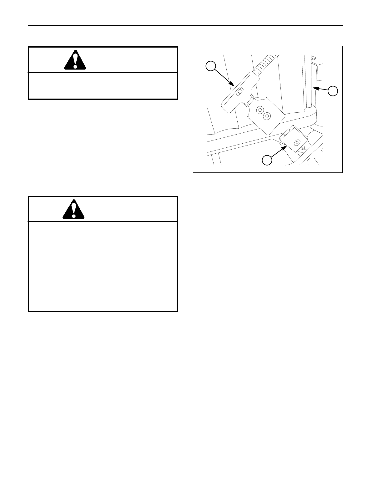
2. Locate the transmissionengage/disengage shaft on
the inside of the transmission next to the battery pack
(Fig. 3).
2
1
CAUTION
Be careful when rotating the transmission engage/disengage lever. The lever is spring loaded
and may cause personal injury.
3. To disengage the spring loaded idler from thetransmission drive belt, use a 3/8” wrench to rotate the engage/disengage shaft 1/4 turn clockwise.
4. To engage the idler into the transmission drive belt,
use a3/8” wrenchto rotate theengage/disengage shaft
1/4 turn counter--clockwise. The transmission belt is
properlytensionedwhenthealignmentmarksontheengage/disengage shaft and the transmission cover are
aligned (Fig. 4).
5. Connectthebatterypack (seeBattery PackConnection in this section).
Figure 3
1. Transmission
2. Engage/disengage shaft
3
Figure 4
1. Engage/disengage shaft
2. Alignment mark
3
3. Battery pack
1
2
3. Cover alignment mark
Drive System
Traction and Reel
Greensmaster eFlex 1800/2100 Traction and Reel Drive SystemPage 3 -- 5
Page 20
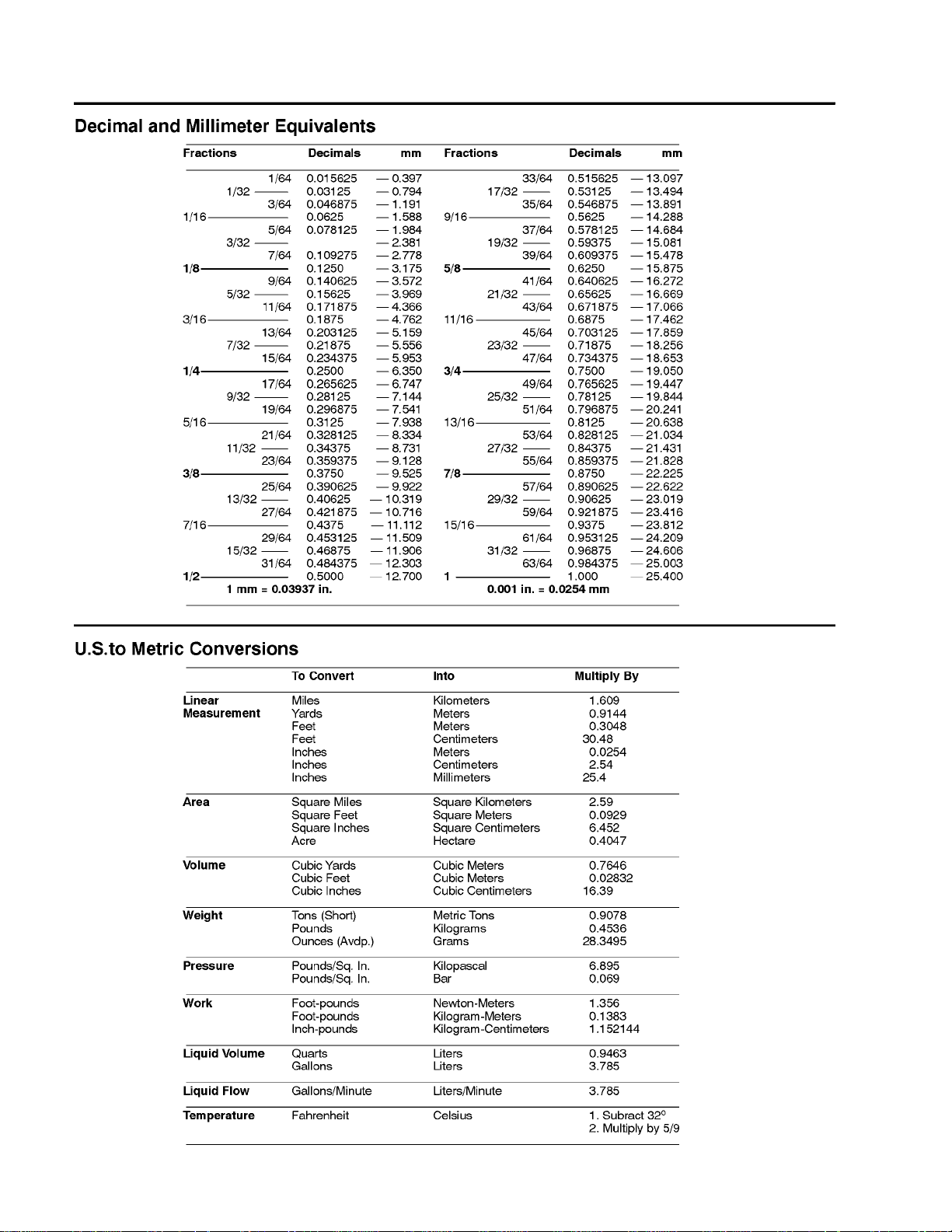
Special Tools
Modified Socket for Reel Clutch Bearing Collar
The modified socket is used to remove and install the
reel clutch bearing collar when servicing the transmission reel clutch shaft (Fig. 5). Refer to Transmission
ReelDrive Systeminthe ServiceandRepairs sectionof
this chapter for complete information on servicing the
reel clutch shaft assembly.
Socket Modification
1. Make sure that socket (9/16” or 15mm) to be modified fits over the reel clutch shaft bearing collar.
2. Drill a hole or grind slots in socket walls to allow a
5/32” pin to extend through socket. A modified socket
with ground slots is shown in Figure 6.
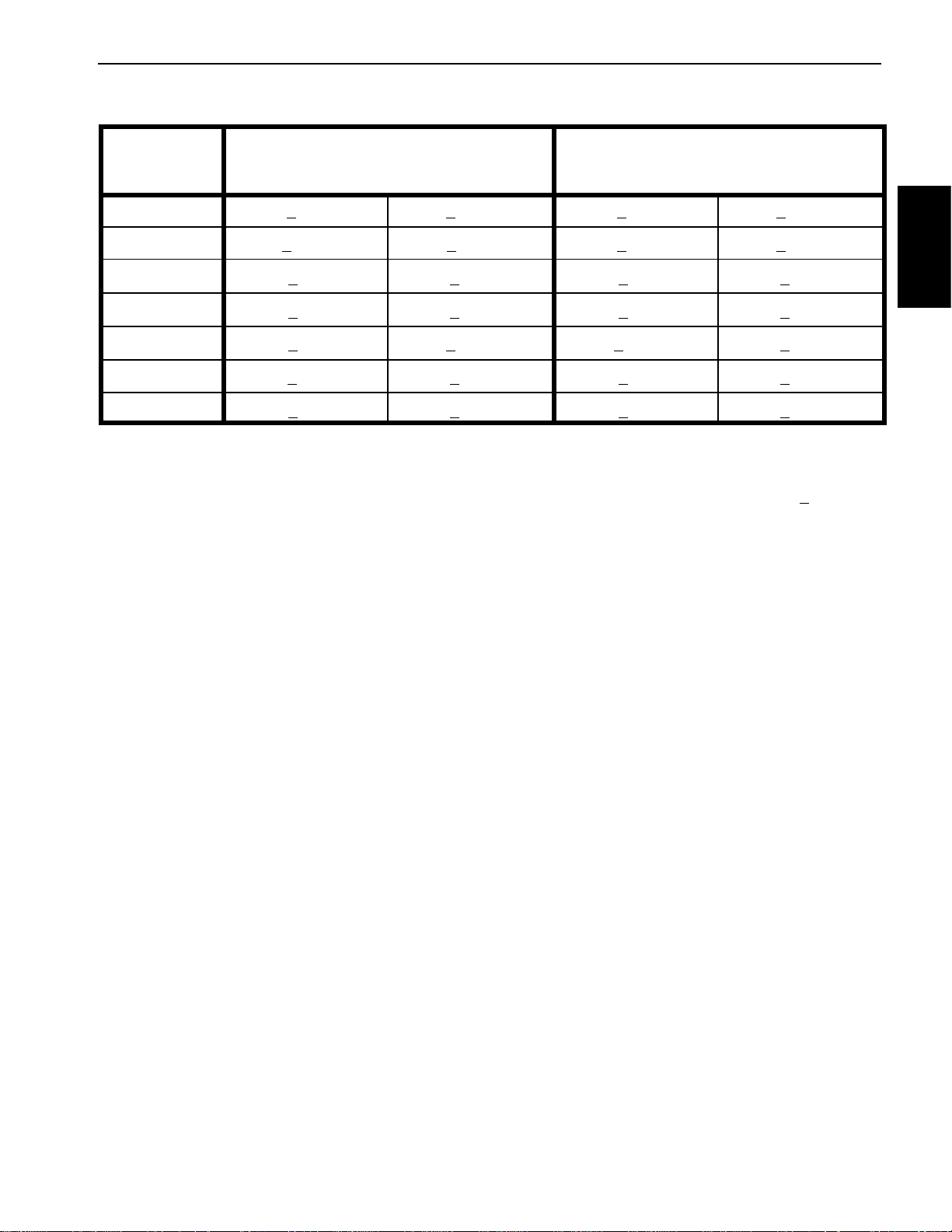
Modified Socket Use ( Fig. 7)
IMPORTANT: To prevent damage, avoid using ex-
cessive clamping pressure on the reel clutch shaft
assembly.
1. Bearing collar
2. Reel clutch shaft
123
Figure 5
3. Hub flat location
1. Use flats on reel drive hub to carefully secure reel
clutchshaft assemblyin avise. Usea visewith softjaws
to prevent damage to clutch shaft assembly components.
2. Slide modified socket over bearing collar.
3. Align modified socket so that 5/32” pin can be inserted through socket and hole in bearing collar.
4. Use modifiedsocket andsocket wrenchto loosenor
tighten bearing collar.
1. Modified socket
2. Reel clutch shaft assy
Figure 6
1
3
2
Figure 7
3. Pin
Greensmaster eFlex 1800/2100Traction and Reel Drive System Page 3 -- 6
Page 21
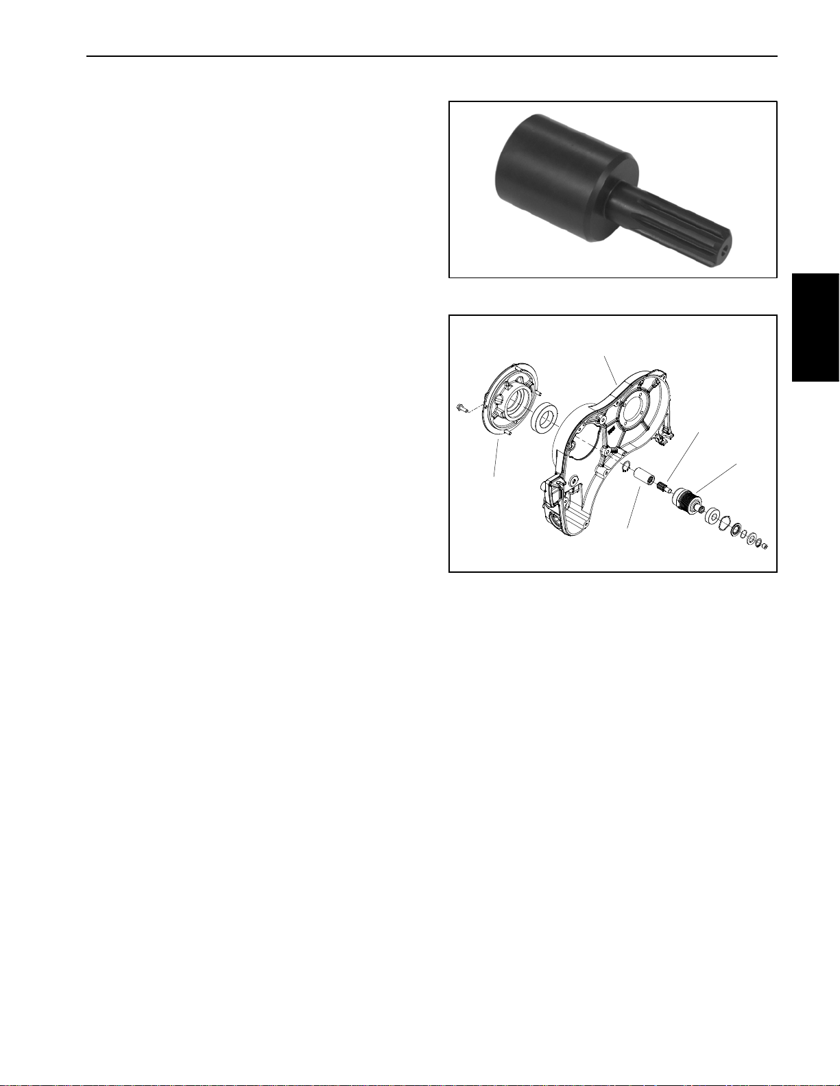
Spline Insert Tool
Usesplineinserttooltoremoveorinstalldrivesplineinto
transmission driven pulley. Referto Transmission Drive
System inthe Service andRepairs section ofthis chapter for complete information on servicing the transmission drive system.
Toro Part Number: TOR4112
Figure 8
2
Drive System
Traction and Reel
4
5
1
1. Motor adapter
2. Transmission housing
3. Splined coupler
3
Figure 9
4. Drive spline
5. Driven pulley
Greensmaster eFlex 1800/2100 Traction and Reel Drive SystemPage 3 -- 7
Page 22

Adjustments
Cutting Unit Clip Adjustment
Cuttingunitclipadjustment on theeFlex1800and eFlex
2100 can bechanged by installing the cutting unit drive
pulleysto the appropriatelocations onthe reel driveassembly.Clip frequencypulley locationsfor 11 bladeand
14 blade cutting units are shown in Figure 11 below.
To adjust clip frequency, follow the following s teps:
1. Parkmachineonlevelsurface.Turnkeyswitchtothe
OFF position and remove key from the switch. Disconnect the battery pack (see Battery Pack Connection in
the General Information section of this chapter).
2. Removereeldrive coverandreel drivebeltfromside
ofcuttingunit (seeReelDriveBelt intheServiceand Repairs section of this chapter).
3. Loosen two(2)set screwsfrom drivepulleys thatare
to be removed. Slide pulleys from shafts.
4. Apply antiseize lubricant to top of woodruff keys.Arrange pulleys on reel drive assembly as needed for desired clip frequency (Fig. 11).
5. Secure all pulleys with two (2) set screws. To rque
screws from 60 to 65 in--lb (6.8 to 7.3 N--m).
2
1. Reel drive cover
2. Reel drive belt
3. Pulley
Antiseize
Lubricant
5
Figure 10
60 to 65 in--lb
(6.8 to 7.3 N--m)
4
3
4. Set screw
5. Woodruff key
1
6. Install reel drive belt and reel drive cover to cutting
unit(see Reel DriveBeltin theServiceand Repairssection of this chapter).
7. Connectthebatterypack (seeBattery PackConnection in the General Information section of this chapter).
POSITIONBLADES
A11 14 B C
0.147 0.115
0.153 0.120
0.160 0.126
CLIP
0.174 0.137
0.182 0.143
0.190 0.149
22
22
24
25
24
25
24 25
25 24
22 25
22 24
25 22
24 22
B
C
A
SET SCREW
60 -- 65 IN LBS
22 TOOTH PULLEY IS ALUMINUM COLOR
24 TOOTH PULLEY IS BLACK COLOR
25 TOOTH PULLEY IS RED COLOR
Figure 11
Greensmaster eFlex 1800/2100Traction and Reel Drive System Page 3 -- 8
Page 23

Reel Clutch Adjustment
To adjust the reel clutch, follow the following steps:
1. Parkmachineonlevelsurface.Turnkeyswitchtothe
OFF position and remove key from the switch. Disconnect the battery pack (see Battery Pack Connection in
the General Information section of this chapter).
2. Remove rubber plugfrom front oftransmission toallow viewing of reel drive clutch components (Fig. 12).
3. Releaseclutch cablespringtension byremovingreel
clutch cable from casting slot of transmission:
6
5
4
A. Loosen upper jam nut that secures reel cable to
casting slot of transmission.
B. Lift cable free from casting slot of transmission.
4. Loosen jam nut that secures set screw position in
reel clutch lever (Fig. 12).
5. Apply light upward pressure against the reel clutch
lever.
6. Backoutsetscrew inreel clutchlever untilreelclutch
hubcauses thetips ofthe reeldrive hubteeth tocontact
the mating reel clutch pulley.
7. While maintaining light pressure on reel clutchlever,
rotate set screw clockwise until a gap of 0.040” to
0.060”(1.0to1.5mm)isattainedbetweenthereeldrive
hub and reel clutch hub.
8. Tighten jam nut to secure adjustment. Make sure
that set screw does not rotate while tightening jam nut.
9. Install rubber plug into front of transmission.
10.Install reel cable to casting slot of transmission and
confirmthatcablespring lengthis properlyset(seeReel
Clutch Cable Replacement in Chapter 5 -- Chassis and
Controls).
7
3
0.040” to 0.060”
(1.0 to 1.5 mm)
1. Reel drive hub tooth
2. Reel drive hub
3. Reel clutch hub
4. Reel clutch lever
1
Drive System
Traction and Reel
12
Light Upward
Pressure
Figure 12
5. Set screw
6. Jam nut
7. Gap location
11.Connect thebattery pack(seeBatteryPackConnection in the General Information section of this chapter).
Greensmaster eFlex 1800/2100 Traction and Reel Drive SystemPage 3 -- 9
2
1. Reel clutch lever
2. Reel clutch hub
4
3
Figure 13
3. Reel drive hub
4. Reel clutch pulley
Page 24

This page is intentionally blank.
Greensmaster eFlex 1800/2100Traction and Reel Drive System Page 3 -- 10
Page 25

Service and Repairs
Reel Drive Belt
EFlex machinesuse apositive drive belton the leftside
of the machine to operate the cutting unit.
Removal
1. Parkmachineonlevelsurface.Turnkeyswitchtothe
OFF position and remove key from the switch. Disconnect the battery pack (see Battery Pack Connection in
the General Information section of this chapter).
2. Remove reel drive cover to expose reel drive belt
(Fig. 14).
3. Loosen the bearing housing mounting nut (Fig. 15).
4. Using a 5/8” (16mm) wrench, rotate the bearing
housing to release tension on reel drive belt (Fig. 15).
5. Remove reel drive belt from the pulleys.
2
Figure 14
1. Reel drive cover 2. Flange head screw
1
Drive System
Traction and Reel
Installation
1. Makesurethat thebattery packisdisconnected(see
Battery Pack Connection in the General Information
section of this chapter).
2. Using a 5/8” (16mm) wrench, rotate and hold the
bearing housingto allow reel drive belt installation (Fig.
15).
3. Place a new drive belt onto the pulleys.
4. Release bearing housing to apply tension to reel
drivebelt. Makesure thatbearing housing rotatesfreely
which will allow accurate belt tension.
5. Rotate reel drive at least one (1) full turn to ensure
that drive belt is properly tensioned.
6. Tighten the bearing housing mounting nut (Fig. 15).
7. Install reel drive cover to machine and secure with
flange head screw (Fig. 14).
8. Connectthebatterypack (seeBattery PackConnection in the General Information section of this chapter).
1. Reel drive belt
2. Bearing housing nut
3
Figure 15
3. Compression spring
4. Bearing housing
4
2
1
Greensmaster eFlex 1800/2100 Traction and Reel Drive SystemPage 3 -- 11
Page 26

Reel Drive Assembly
27
20
Antiseize
Lubricant
12
22
Antiseize
3
16
Lubricant
21
60 to 65 in--lb
2
(6.8 to 7.3 N--m)
17
18
24
25
22
4
23
10
14
26
6
9
1
23
19
24
7
22
28
RIGHT
FRONT
Antiseize
Lubricant
Figure 16
1. Reel drive housing
2. O--ring
3. Carriage screw
4. Washer head screw
5. Flange head screw (2 used)
6. Hex nut (2 used)
7. Reel drive shaft
8. Reel pulley (22 tooth) (aluminum)
9. O--ring
10. Reel idler shaft
11. Reel pulley (24 tooth) (black)
12. Bearing housing assembly
13. Cover plug
14. Reel pulley (25 tooth) (red)
15. Belt
16. Compression spring
17. Hardened washer
18. Hex nut
19. Reel drive cover
NOTE: Cutting unit clip adjustment on the eFlex 1800
and eFlex 2100 is adjusted by installing the cutting unit
drivepulleys(items8,11and14)tothe appropriate locations on the reel drive assembly (see Cutting Unit Clip
Adjustment in the Adjustments section of this chapter).
5
11
8
15
13
20. Shoulder bolt
21. Spring pin
22. Woodruff key (3 used)
23. Set screw (2 used per pulley)
24. Ball bearing (2 used)
25. Spacer
26. Push nut
27. Cutting unit
28. Flange head screw
Greensmaster eFlex 1800/2100Traction and Reel Drive System Page 3 -- 12
Page 27

Reel Drive Assembly Removal (Fig. 16)
1. Parkmachineonlevelsurface.Turnkeyswitchtothe
OFF position and remove key from the switch. Disconnect the battery pack (see Battery Pack Connection in
the General Information section of this chapter).
2. Slide the telescoping coupler off the cutting unit hex
shaft (Fig. 17).
3. Removereeldrive belt (seeReelDriveBeltReplacement in this section).
4. Loosen two (2) set screws (item 23) that secure reel
pulley (item 8) to reel drive shaft (item 7). Slide pulley
from drive shaft. Locateand retrieve woodruff key (item
22) from shaft.
5. Remove washer head screw (item 4) that secures
reel drive housing to cutting unit side plate.
NOTE: Hex nuts (item6) haveadhesive appliedduring
cutting unit production. The nuts should remain in cutting unit side plate during reel drive housing removal.
6. Remove two (2) flange headscrews (item5) thatsecure reel drive housing to cutting unit side plate.
3. Position reel drive assembly to cutting unit. Make
sure that spring pin (item 21) and compression spring
(item16) arepositionedbetween reeldrive housingand
bearing housing assembly.
4. Secure reeldrive assembly with two (2)flange head
screws (item 5) and washer head screw (item 4).
5. Install woodruff key(item 22) to reel driveshaft (item
7). Apply antiseize lubricant to top of key.
6. Slide reel pulley (item 8) onto reel drive shaft until it
contacts shoulder on shaft. Secure reel pulley with two
(2) set screws (item 23). Torque set screws from 60 to
65 in--lb (6.8 to 7.3 N--m).
7. Install reel drive belt (see Reel Drive Belt Replacement in this section). Make sure that reel drive cover is
securedtohousingafterbeltinstallation.
8. Slide the telescoping coupler onto the cutting unit
hex shaft (Fig. 17).
9. Connectthebatterypack (seeBatteryPackConnection in the General Information section of this chapter).
Drive System
Traction and Reel
7. Remove reel drive assembly from cutting unit.
8. Remove components from reel drive housing as
necessary using Figure 16 as a guide.
A. If idlershaft bearings(item24) are toberemoved,
use press to remove bearings and bearing spacer
from shaft. Discard bearings after removal.
NOTE: See Reel Drive Bearing Housing in this section
for disassembly and assembly information of bearing
housing assembly (item 12).
NOTE: Reel pulleys (items 8,11and 14) can beidentified by color and number of teeth. Pulley location can
vary based on desired cutting unit clip frequency (see
Cutting UnitClip Adjustment inthe Adjustments section
of this chapter).
Reel Drive Assembly Installation (Fig. 16)
1. Install allremoved components to reeldrive housing
using Figure 16 as a guide.
A. If bearings (item 24) were removed from idler
shaft, use press to install bearings and bearing
spacer onto shaft.
1
2
Figure 17
1. Telescoping coupler 2. Cutting unit hex shaft
2. Apply light coating of grease on reel drive housing
O--rings (items 2 and 9).
Greensmaster eFlex 1800/2100 Traction and Reel Drive SystemPage 3 -- 13
Page 28

Reel Drive Bearing Housing
11
10
8
6
13
12
1. Retaining ring
2. Reel input shaft
3. Bearing (2 used)
4. Bearing spacer
5. Wave washer
9
7
Figure 18
6. Flocked bearing shield
7. Wave spring
8. Flat washer
9. Retaining ring
5
3
2
1
4
10. Bearing housing
11. Spring pin (2 used)
12. Flex coupling
13. Reel hex shaft
Greensmaster eFlex 1800/2100Traction and Reel Drive System Page 3 -- 14
Page 29

Disassembly (Fig. 18)
Assembly (Fig. 18)
1. Parkmachineonlevelsurface.Turnkeyswitchtothe
OFF position and remove key from the switch. Disconnect the battery pack (see Battery Pack Connection in
the General Information section of this chapter).
2. Remove reel drive bearing housing from reel drive
housing (see Reel Drive Assembly in this section).
3. Removeretainingring(item 1)from bearinghousing.
4. Slide reel input shaft assembly from bearing housing. Remove wave washer (item 5) from bearing housing.
IMPORTANT: When removing flexcoupler (item 12)
from reel input shaft (item 2), do not mar outer surface of coupler (e.g. grasping with pliers or mounting in vise) as coupler may be damaged and fail
prematurely.
5. Supportflex coupler(item12) to preventitfrombeing
damaged during spring pin removal. Push spring pin
fromflex couplerandreel inputshaft.Slide couplerfrom
shaft and discard spring pin.
6. Remove retaining r ing (item 9) from shaft. Then remove flat washer (item 8), wave spring (item 7) and
flocked bearing shield (item 6) from shaft. Note orientation of flocked shield for assembly purposes.
7. Press bearingsand bearingspacerfromshaft ifnecessary. Discard bearings if removed.
8. Clean all bearing housing components.
1. Ifbearingswereremovedfromreelinputshaft, install
new bearings onto shaft. Press first bearing fully onto
shaft. Position spacer on shaft and then press second
bearing onto shaft.
2. Install flocked bearing shield (item 6), wave spring
(item 7) and then flat washer (item 8) onto reel input
shaft. Secure components to shaft with retaining ring
(item 9). It may be necessary to drive the retaining ring
onto theinput shaft with atubular tool and mallet.Make
sure that retaining ring is fully seated into shaft groove
after installation.
3. Place wave washer (item 5) into bearing housing.
4. Fillcavitybetween bearingswithMobilHighTemperature XHP--222 grease (or equivalent).
5. Installreel inputshaftassembly into bearinghousing
andsecurewithretainingring(item1).
IMPORTANT: When installing flex coupler (item 12)
onto reel input shaft (item 2), do not mar outer surface of coupler (e.g. grasping with pliers or mount ing in vise) as coupler may be damaged and fail
prematurely.
6. Slide flex coupler onto reel input shaft, supportcoupler to prevent it from being damaged during spring pin
installation. Installnew spring pin into coupler to secure
it to shaft.
7. Install reel drive bearing housing to reel drive housing (see Reel Drive Assembly in this section).
Drive System
Traction and Reel
8. Connectthebatterypack (seeBatteryPackConnection in the General Information section of this chapter).
Greensmaster eFlex 1800/2100 Traction and Reel Drive SystemPage 3 -- 15
Page 30

Drum Drive Belt
12
See text for
tightening
procedure
2
11
9
6
14
13
4
8
7
5
3
10
15 to 17 ft--lb
(21to23N--m)
18
17
16
15
1
2
Figure 19
1. Drum drive cover
2. Washer head screw (7 used)
3. Gasket
4. Wave washer
5. Gear assembly
6. Retaining ring
7. Brake band
8. Brake mount pin
9. Extension spring
10. Drum drive belt
11. Brake clevis pin
12. Drum drive housing
The drum drive system on eFlex 1800 and eFlex 2100
machines uses a multi--ribbed poly--V drive belt on the
right side of the traction drum.
Removal (Fig. 19)
1. Parkmachineonlevelsurface.Turnkeyswitchtothe
OFF position and remove key from the switch. Disconnect the battery pack (see Battery Pack Connection in
the General Information section of this chapter).
2. Remove transport wheelsif attached (see Transport
Wheelsin the Serviceand Repairs s ection of Chapter6
-- Chassis and Controls).
13. Retaining ring
14. Idler pulley assembly
15. Shoulder screw
16. Idler arm assembly
17. Washer head screw (4 used)
18. Drive pulley (from transmission)
3. Rotatetractionengage/disengagelever tothedisengaged position to remove tension from the drum drive
belt(Fig. 20) (seeDisengagingDrum DriveFromTransmission inthe General Information sectionof this chapter).
4. Remove seven (7) washer head screws that secure
the drum drive cover.Removecover to exposethe traction drive belt.
5. Remove and discard gasket (item 3) from between
cover and housing.
Greensmaster eFlex 1800/2100Traction and Reel Drive System Page 3 -- 16
Page 31

6. Remove retaining ring (item 6) that secures brake
band to brake clevis pin. Slide brake band from brake
clevis and brake mount pins and remove band from
drum drive housing.
7. Carefully remove one end of extension spring (item
9) from anchor point and rotate spring away from drive
belt.
8. Pivot the idler pulley away from the drum drive belt
to loosen belt tension (Fig. 21).
9. Remove drum drive belt from drive pulley and then
from differential pulley.
Installation (Fig. 19)
1. Makesurethat thebattery packisdisconnected(see
Battery Pack Connection in the General Information
section of this chapter).
2. Placedrumdrivebeltontodifferentialpulleyandthen
fit beltto drive pulley. Make sure thatbelt is onrear side
of idler pulley.
3. Carefully install removed end of extension spring
(item 9) to anchor point.
4. Install brake band over brake surface of differential
pulley. Slide ends of brake band onto brake clevis and
brakemountpins. Secure brakebandtobrake clevispin
with retaining ring (item 6).
1
2
Figure 20
1. Traction lever (engaged) 2. RH handle clamp
Drive System
Traction and Reel
2
3
1
5. Make surethat wave washer (item 4) is pressed into
bore of drum drive cover.
6. Position new gasket (item 3) to housing surface.
7. Slide drum drive cover onto drum drive assembly.
8. Install seven(7) washer head screws to securecover to housing. Tighten screws as follows:
A. F irst, using an alternating crossing pattern,
torque all screws from 15 to 40 in--lb (1.7 to 4.5
N--m).
B. Again using an alternating crossing pattern,
torque all screws from 85 to 95 in--lb (9.6 to 10.7
N--m).
9. Rotate traction engage/disengage lever to the engaged position to tension the drum drive b elt (Fig. 20).
10.Install transport wheels if they were attached (see
Transport Wheels in the Service and Repairs section of
Chapter 6 -- Chassis and Controls).
11.Connect thebattery pack(seeBatteryPackConnection in the General Information section of this chapter).
5
1. Traction drive belt
2. Drive pulley
3. Idler pulley
4
Figure 21
4. Differential pulley
5. Brake band
Greensmaster eFlex 1800/2100 Traction and Reel Drive SystemPage 3 -- 17
Page 32

Drum Drive Idler Assembly
12
See text for
tightening
procedure
2
11
9
6
14
13
4
8
7
5
3
10
15 to 17 ft--lb
(21to23N--m)
18
17
16
15
1
2
Figure 22
1. Drum drive cover
2. Washer head screw (7 used)
3. Gasket
4. Wave washer
5. Gear assembly
6. Retaining ring
7. Brake band
8. Brake mount pin
9. Extension spring
10. Drum drive belt
11. Brake clevis pin
12. Drum drive housing
Removal
1. Parkmachineonlevelsurface.Turnkeyswitchtothe
OFF position and remove key from the switch. Disconnect the battery pack (see Battery Pack Connection in
the General Information section of this chapter).
2. Remove transport wheelsif attached (see Transport
Wheelsin the Serviceand Repairs s ection of Chapter6
-- Chassis and Controls).
3. Rotatetractionengage/disengageleverto the disengaged position to remove tension from the drum drive
belt (see Disengaging Drum Drive From Transmission
in the General Information section of this chapter).
13. Retaining ring
14. Idler pulley assembly
15. Shoulder screw
16. Idler arm assembly
17. Washer head screw (4 used)
18. Drive pulley (from transmission)
4. Remove seven (7) washer head screws that secure
thedrumdrive cover.Removecover toexposethe drum
drive system.
5. Remove and discard gasket (item 3) from between
cover and housing.
6. Carefully remove the end of the extension spring
(item9)fromidlerarm.
7. Remove shoulder screw (item 15) that secures the
idler arm assembly to the drum drive housing. Remove
idler arm assembly from housing.
Greensmaster eFlex 1800/2100Traction and Reel Drive System Page 3 -- 18
Page 33

8. Disassemble idler arm assembly as needed (Fig.
23). Replaceworn or damaged bearings and bushings.
A. Remove flange bushings from idler bracket.
B. Remove retaining ring from idler bracket. Slide
idler pulley from bracket shaft. Press ball bearings
from idler pulley.
2
3
Installation
1. If idler arm assembly was disassembled (Fig. 23):
A. Press new flange bushings into idler bracket.
B. Pressnewballbearingsfully intoidler pulleymak-
ingsure toapply pressuretoouter bearingrace only.
Slide pulley assembly onto idlerbracket and secure
with retaining ring.
2. Position idler arm assembly to drum drive housing
andsecurewith shoulderscrew (item15).Torqueshoulderscrewfrom15to17ft--lb(21to23 N--m).Checkthat
idler arm assembly can pivot freely after tightening
shoulder screw.
3. Carefully secure the end of the extension spring
(item 9) to idler arm.
4. Make surethat wave washer (item 4) is pressed into
bore of drum drive cover.
5. Position new gasket (item 3) to housing surface.
6. Slide drum drive cover onto drum drive assembly.
5
Figure 23
1. Flange bushing (2 used)
2. Idler bracket
3. Ball bearing (2 used)
1
4
4. Idler pulley
5. Retaining ring
Drive System
Traction and Reel
7. Install seven(7) washer head screws to securecov-
er to housing. Tighten screws as follows:
A. F irst, using an alternating crossing pattern,
torque all screws from 15 to 40 in--lb (1.7 to 4.5
N--m).
B. Again using an alternating crossing pattern,
torque all screws from 85 to 95 in--lb (9.6 to 10.7
N--m).
8. Rotate traction engage/disengage lever to the en-
gagedpositiontotensionthedrumdrive belt(see Disengaging Drum Drive From Transmission in the General
Information section of this chapter).
9. Install transport wheels if they were attached (see
Transport Wheels in the Service and Repairs section of
Chapter 6 -- Chassis and Controls).
10.Connectthe batterypack(seeBatteryPackConnec-
tion in the General Information section of this chapter).
Greensmaster eFlex 1800/2100 Traction and Reel Drive SystemPage 3 -- 19
Page 34

Traction Drums
9
Antiseize
7
Lubricant
6
RIGHT
FRONT
10
11
140 to 160 ft--lb
(190 to 216 N--m)
75 to 90 ft--lb
(102 to 122 N--m)
12
29
17
6
8
17
13
14
70 to 80 ft--lb
(95 to 108 N--m)
27
28
15
30
5
3
4
3
1
18
2
3
22
21
20
3
19
26
22
14
23
24
16
25
Figure 24
1. Drum drive housing
2. Straight bushing
3. Flange bushing (4 used)
4. Brake lever
5. Traction lever
6. Square key (2 used)
7. Drum shaft
8. Long spur gear
9. Differential assembly
10. RH traction drum
11. Jam nut
12. Grease seal
13. LH traction drum
14. Ball bearing (2 used)
15. Bearing nut
16. LH hex shaft
17. Straight bushing (2 used)
18. Dowel pin (2 used)
19. Cap screw
20. Flat washer
Traction Drum Removal (Fig. 24)
1. Parkmachineonlevelsurface.Turnkeyswitchtothe
OFF position and remove key from the switch. Disconnect the battery pack (see Battery Pack Connection in
the General Information section of this chapter).
2. If installed, remove transport wheels (see Transport
Wheelsin the Serviceand Repairs s ection of Chapter6
-- Chassis and Controls).
21. Traction engage lever
22. Retaining ring (2 used)
23. Brake lever
24. Retaining ring
25. LH side plate
26. Washer head screw
27. Lock collar
28. Pin
29. Thrust washer
30. O--ring
3. Remove handle assembly from machine (see Handle Assembly in the Service and Repairs section of
Chapter 6 -- Chassis and Controls).
4. Supportbothsidesof machine framewithjackstands
or suitable blocking to prevent the machine from moving.
Greensmaster eFlex 1800/2100Traction and Reel Drive System Page 3 -- 20
Page 35

5. Separate LHside plate (item25) from machine(Fig.
25):
1
A. Remove flange nut, hardened washer and carriagescrew(items3,4and6inFig.25)thatsecure
LH side plate to rear frame.
B. Remove three (3) flange screws and hardened
washers (items 8 and 4 in Fig. 25) that secure LH
side plate to frame.
C. Slide LH side plate from supporting bearing and
remove from machine.
6. Insertbar stockorother suitable toolthroughspokes
of LH traction drum to keep drum from turning.
7. WhileretainingLHdrum,loosenandremovebearing
nut (item 15) from traction drum assembly. The ball
bearing(item14)ispressedontothebearingnutsoitwill
be removed with the nut.
8. SlideLH tractiondrum(item 13)fromdrum shaft.Lo-
cate and retrieve square key from shaft.
9. If necessary, carefullyremove grease seal (item 12)
from LH traction drum taking care to not damage bore
of drum. Discard removed seal.
2
3
4
1. Kickstand
2. Rear frame
3. Flange nut
4. Hardened washer
5. Frame
6. Carriage screw
5
Figure 25
11
10
6
7
4
8
7. LH side plate
8. Flange screw (3 used)
9. Counterweight
10. Offset handle clamp
11. Handle clamp
9
Drive System
Traction and Reel
10.If necessary, removeLH hex shaft (item 16) and ball
bearing (item 14) from bearing nut.
1 1.Insertbar stockor othersuitabletool throughspokes
of RH traction drum to keep drum from turning.
12.Remove O--ring (item 30),pin (item 28)and lock col-
lar (item 27) from drum shaft.
13.While retaining remainingdrum, loosen andremove
jam nut (item 11) from long spur gear.
14.Remove RH traction drum (item 10) from machine.
Locate and retrieve square key from spur gear.
NOTE: If removal of the drum shaft (item 7), long spur
gear (item 8) or differential assembly (Item 9) is necessary, see Differential Assembly in this section.
Traction Drum Installation (Fig. 24)
1. Make sure that drum shaft (item 7), long spur gear
(item 8) and differential assembly (Item 9) are installed
to drum drive housing (refer to Differential Assembly in
4. Align slot in RH traction drum (item 10) with key on
long spur gear and slide traction drum onto gear.
this section).
5. Insert barstock orother suitabletool throughspokes
2. Install LH hex shaft (item 16) and ball bearing (item
of RH traction drum to keep drum from turning.
14)to bearingnut (item 15) if they were removed. Press
bearing fullyonto bearing nut.Torque hexshaft from 70
to 80 ft--lb (95 to 108 N--m).
6. Install jam nut (item 11) onto threads of long spur
gear to secure RH traction drum. Torque jam nut from
140 to 160 ft--lb (190 to 216 N--m).
3. Place square key (item 6) into slot of long spurgear
(item 8). Apply antiseize lubricant to top surface of key.
Greensmaster eFlex 1800/2100 Traction and Reel Drive SystemPage 3 -- 21
1
2
0.470” to 0.530”
(12.0 to 13.4 mm)
Figure 26
1. LH traction drum 2. Grease seal
Page 36

7. Slide lock collar (item 27) onto drum shaft. Align
holesin collarand shaftand theninstallpin (item28).Fit
O--ring (item 30) to slot in collar.
13.Secure LH side plate(item 25) to machine (Fig.25):
A. Slide LH side plate onto supporting bearing.
8. If grease seal (item 12) was removed from LH traction drum, installnew grease seal into drum. Makesure
that seal lip is orientated toward center of drum. Press
sealinto drumbore sothat sealis recessedfrom 0.470”
to0.530”(12.0to13.4mm)fromedgeofdrum(Fig.26).
9. Placesquare key(item 6) intoslot ofdrum shaft.Apply antiseize lubricant to top surface of key.
10.Align slot in LH traction drum (item 13) with key on
drum shaft and carefully slide traction drum onto shaft
taking care to not damage grease seal in drum.
11.Insert barstock orothersuitable t ool throughspokes
of LH traction drum to keep drum from turning.
12.Make sure thatball bearing (item14)is pressedonto
the bearing nut (item 15). While retaining LH drum, secure drum to traction drum assembly with bearing nut
(item 15). Torque bearing nut from 75 to 90 ft--lb (102
to 122 N--m).
B. Secure LH side plate to frame with three (3)
flange screws and hardened washers.
C. Secure LH side plate to rear frame with carriage
screw, hardened washer and flange nut.
14.Install handle assemblyto machine (see Handle As-
sembly in the Service and Repairs sectionof Chapter 6
-- ChassisandControls).Makesure thatallcableadjust-
ments are correct.
15.Install transport wheels if necessary (see Transport
Wheels in the Serviceand Repairs sectionof Chapter6
-- Chassis and Controls).
16.Connectthe battery pack(seeBatteryPackConnec-
tion in the General Information section of this chapter).
Greensmaster eFlex 1800/2100Traction and Reel Drive System Page 3 -- 22
Page 37

This page is intentionally blank.
Drive System
Traction and Reel
Greensmaster eFlex 1800/2100 Traction and Reel Drive SystemPage 3 -- 23
Page 38

Differential Assembly
9
31
Antiseize
7
Lubricant
6
RIGHT
FRONT
10
11
140 to 160 ft--lb
(190 to 216 N--m)
75 to 90 ft--lb
(102 to 122 N--m)
12
29
17
6
8
17
13
14
70 to 80 ft--lb
(95 to 108 N--m)
27
28
15
30
5
3
4
3
1
18
2
3
22
21
20
3
19
26
14
22
23
24
Loctite #242
16
25
Figure 27
1. Drum drive housing
2. Straight bushing
3. Flange bushing (4 used)
4. Brake lever
5. Traction lever
6. Square key (2 used)
7. Drum shaft
8. Long spur gear
9. Differential assembly
10. RH traction drum
11. Jam nut
12. Grease seal
13. LH traction drum
14. Ball bearing (2 used)
15. Bearing nut
16. LH hex shaft (LH threads)
17. Straight bushing (2 used)
18. Dowel pin (2 used)
19. Cap screw
20. Flat washer
21. Traction engage lever
Disassembly (Fig. 27)
1. Parkmachineonlevelsurface.Turnkeyswitchtothe
OFF position and remove key from the switch. Disconnect the battery pack (see Battery Pack Connection in
the General Information section of this chapter).
22. Retaining ring (2 used)
23. Brake lever
24. Retaining ring
25. LH side plate
26. Washer head screw
27. Lock collar
28. Pin
29. Thrust washer
30. O--ring
31. Spur gear assembly
2. Remove traction drums from machine (see Traction
Drums in this section).
3. Slide spurgear assembly from differentialassembly
in drum drive housing (Fig. 28).
Greensmaster eFlex 1800/2100Traction and Reel Drive System Page 3 -- 24
Page 39

4. If necessary,disassemble spur gear assembly (Fig.
29).
A. The hex shaft has left hand threads. The shaft
also has thread locking compound on threads.
B. Press ball bearing and flange bushing from spur
gear as needed.
IMPORTANT: As drum shaft(item 7)and differential
assembly (item 9) are removed, make sure to retrieve and note location of thrust washer (item 29)
for assembly purposes.
4. Place thrust washer (item 29) onto drum shaft (item
7). Insert drum shaft into differential assembly. Make
surethatdrumshaftproperlyengagesdifferentialgears.
5. Install traction drums to machine (see Traction
Drums in this section).
6. Installdrum drive beltfrom machine(seeDrumDrive
Belt in this section).
7. Connectthebatterypack (seeBatteryPackConnection in the General Information section of this chapter).
5. Pushdrum shaft(item 7)out ofdifferential assembly.
Makesuretolocateand retrievethrustwasher(item29).
6. Slide differentialassembly from long spurgear (item
8) and drum drive housing (item 1).
NOTE: For differentialserviceprocedure, seeDifferential Assembly Service in this section.
7. If necessary, slide longspur gear (item 8) from drum
drive housing. Straight bushings (item 17) in long spur
gear should be inspected for wear or damage and replaced if needed.
8. Ballbearing (item14) thatsupports longspur gearis
pressed into drum drive housing. Make sure that bearing is in good condition and is pressed fully to shoulder
of housing.
Assembly (Fig. 27)
1. If long spur gear (item 8) was removed from drum
drive housing,slide gear into ballbearing in drivehousing.
2. If spur gear assembly (Fig. 29) was taken apart, as-
semble as necessary:
1
Drive System
Traction and Reel
2
Figure 28
1. Drum drive housing 2. Spur gear assembly
1
70 to 80 ft--lb
(95 to 108 N--m)
4
A. Press new ball bearing fully onto spur gear if removed.
B. Press new flange bushing into spur gear if removed.
C. If the hex shaft was removed from the spur gear,
apply Loctite #242 (or equivalent) to threads of hex
shaft. Install hex shaft (left hand threads) into spur
gearandtorquefrom 70to80 ft--lb (95to108N--m).
3. Make sure that differential housing cavity is packed
20% to 30% full of high temperature Mobil XHP--222
grease (or equivalent). Slide differential assembly into
drum drive housing (item 1) and onto long spur gear
(item8). Makesure thatspur gearproperlyengages differential gears.
Greensmaster eFlex 1800/2100 Traction and Reel Drive SystemPage 3 -- 25
3
1. Spur gear
2. Ball bearing
2
Figure 29
3. Hex shaft (LH threads)
4. Flange bushing
Page 40

Differential Assembly Service
99 to 121 in--lb
(11.2 to 13.6 N--m)
5
3
1
5
4
6
6
7
8
3
6
2
Figure 30
1. Housing
2. Cover
3. Ball bearing (2 used)
4. Pin (6 used)
5. Dual spur gear (6 used)
6. Spacer (9 used)
Disassembly (Fig. 30)
1. Remove differential assembly from machine (see
Differential Assembly in this section).
2. Remove six(6) socket headscrews that securecovertohousing.Notealignmentof indexmarks onhousing
and cover for assembly purposes (Fig. 31).
3. Placedifferential assemblyonworkbenchso thatthe
differential is resting onthe cover withhousing orientated up.
4
7. Spur gear (3 used)
8. Socket head screw (6 used)
6. Slide each pin with gears and spacers from cover.
Notelocation of gearsandspacers oneachof thesix(6)
pins.
7. If necessary, remove ball bearings from cover and
housing. There are two (2) holes in thecover and housing that allow use of a pin punch to remove bearings.
Discard removed bearings.
Inspection (Fig. 30)
1. Clean all differential components.
4. Lift housing from differentialassembly leaving internalcomponents positionedon cover.Forassemblypurposes, note that index mark on housing is aligned with
a pin that has one (1) gear (Fig. 32).
5. Note locations of projections on inside of cover for
assemblypurposes. Theprojections needto be aligned
with the pins that have one (1) gear (Fig. 33).
2. Inspect all differential gears carefully looking for
chipped teeth, wear or other damage. Because gear
tooth damage is rarely isolated to one gear, replace
gears as a complete set if internal damage is found.
3. Inspect gear pins (item 4) for scoring or wear.
4. Replace all worn or damaged differential assembly
components.
Greensmaster eFlex 1800/2100Traction and Reel Drive System Page 3 -- 26
Page 41

Assembly (Fig. 30)
1. If ball bearing was removed from either cover or
housing,press newballbearing intobearing bore.Make
sure that bearing is fully pressed to shoulder of bore.
2. Place cover (with bearing installed) on workbench.
3. Slide each pin with gears and spacers into cover.
Makesurethatprojectionsoninsideofcover are aligned
with the pins that have one (1) gear (Fig. 33).
4. Positionhousingontoassembly makingsure thatpin
with one (1) gear is positioned next to index mark on
housing (Fig. 32). Also, align index marks on housing
and cover during assembly (Fig. 31).
5. After housing is installed, use one of the spur gears
(see Differential Assembly in this section) to rotate differential gears making sure that they rotate freely without binding. If binding is noted, identify and correct
cause before securing the cover.
6. Secure cover to housing with six (6) socket head
screws. Torque screws from 99 to 121 in--lb (11.2 to
13.6 N--m).
7. Pack differential housing cavity 20% to 30% full of
high temperature Mobil XHP --222 grease (or equivalent).
2
1
Figure 31
1. Cover index mark 2. Housing index mark
1
3
2
2
Drive System
Traction and Reel
8. Install differential assembly to machine (see Differ-
ential Assembly in this section).
3
2
1. Housing index mark
2. Pin with 2 gears
2
3
2
Figure 32
3. Pin with 1 gear
3
3
1
2
3
Greensmaster eFlex 1800/2100 Traction and Reel Drive SystemPage 3 -- 27
1. Projection on cover
2. Pin with 2 gears
Figure 33
3. Pin with 1 gear
Page 42

Transmission Drive Belt
1
See text for
tightening
4
procedure
6
5
2
RIGHT
3
FRONT
1. Transmission assembly
2. Transmission belt
3. Gasket
4. Wave washer (2 used)
5. Transmission cover
6. Washer head screw (7 used)
Transmission removal from the machine is not necessary to service the transmission drive belt. The transmission drive belt can be replaced by removing the
battery packfrom the frame, removing thetransmission
cover and then removing the drive belt.
Drive Belt Removal (Fig. 34)
1. Parkmachineonlevelsurface.Turnkeyswitchtothe
OFF position and remove key from the switch. Disconnect the battery pack (see Battery Pack Connection in
the General Information section of this chapter).
2. Remove battery pack from machine (see Battery
Pack in the Service and Repairs section of Chapter 4 -Electrical System).
7
8
4
Figure 34
7. Drive shaft wire
8. Telescoping coupler
IMPORTANT: During disassembly, make sure that
tension is released from transmission belt before
removing transmission cover.
4. Remove tensionon transmission beltby rotatingthe
engage/disengage shaft clockwise (see Transmission
BeltTensioner inthe GeneralInformation sectionof this
chapter).
5. Remove seven (7) washer head screws that secure
transmission cover to transmission. Carefully remove
cover from transmission. Remove and discard gasket
(item 3).
6. Make sure that wave washers (item 4) remain in
bearing bores of transmission cover.
3. Usetips ofneedle nosepliersto spreadends ofdrive
shaft wire (item 7) in telescoping coupler (item 8). With
wireendsspread, slidecouplerfrom t ransmission shaft.
7. Note transmission belt routing for assembly purposes (Fig. 35).
Greensmaster eFlex 1800/2100Traction and Reel Drive System Page 3 -- 28
Page 43

8. Remove transmission belt from drive and idler pul-
leys in transmission.
9. Check conditionof all pulleys and idlercomponents.
10.Clean inside of transmission before installing new
belt.
2
4
5
1
Drive Belt Installation (Fig. 34)
IMPORTANT: During assembly, make sure that
transmissioncover isinstalled withfasteners properly torqued before applying tension to transmission belt.
1. Install new transmission belt onto pulleys in trans-
mission. Make sure that belt is correctly routed around
drive and idler pulleys (Fig. 35).
2. Make sure that wave washers (item 4) are pressed
into bearing bores of transmission cover. Also, make
surethat two(2)dowel pinsarepressed intoboresinthe
transmission housing.
3. Positionnew gasketto transmissionassembly.Align
gasket to two (2) dowel pins in transmission housing.
4. Installtransmissioncover.If n ecessary,usea rubber
mallet at dowel locations(Fig. 36)to seatcover totransmission.
5. Install seven(7) washer head screws to securecov-
er to transmission. Tighten screws as follows:
6
Figure 35
1. Engage/disengage shaft
2. Drive pulley
3. Reel clutch pulley
2
1
4
3
Drive System
Traction and Reel
4. Idler pulley
5. Drum drive pulley
6. Idler pulley
A. F irst, using an alternating crossing pattern,
torque all screws from 15 to 40 in--lb (1.7 to 4.5
N--m).
B. Again using an alternating crossing pattern,
torque all screws from 85 to 95 in--lb (9.6 to 10.7
N--m).
6. Applytension totransmission beltby rotating theen-
gage/disengage shaft counter--clockwise ( see Transmission Belt Tensioner in the General Information
section of this chapter).
7. Slide telescoping coupleronto transmission shaft so
thatdrive shaftwire engages hexshaft ontransmission.
Make sure that telescopingcoupler isproperly attached
to cutting unit hex shaft.
8. Install battery pack to machine (see Battery Pack in
theServiceand RepairssectionofChapter 4-- Electrical
System).
9. Connectthebatterypack (seeBattery PackConnec-
tion in the General Information section of this chapter).
2
Figure 36
1. Transmission cover 2. Dowel location
Greensmaster eFlex 1800/2100 Traction and Reel Drive SystemPage 3 -- 29
Page 44

Transmission Idler System
4
2
5
7
13
15 to 17 ft--lb
(21 to 23 N--m)
7
10
12
14
11
10
6
3
9
8
1
RIGHT
FRONT
1. Transmission cover
2. Engage/disengage shaft
3. Transmission belt
4. Extension spring
5. Main drive idler
6. Driven pulley (drum drive)
7. Flange bushing (4 used)
8. Cap screw (2 used)
9. Idler pulley bushing (2 used)
10. Ball bearing (6 used)
Transmission removal from the machine is not necessaryto servicethe transmissionidler system.Transmissionidlercomponentscanbe accessed byremovingthe
battery packfrom the frame, removing thetransmission
cover and then removing the drive belt.
Figure 37
11. Idler pulley (2 used)
12. Idler pulley
13. Shoulder screw
14. Retaining ring
Greensmaster eFlex 1800/2100Traction and Reel Drive System Page 3 -- 30
Page 45

Disassembly (Fig. 37)
1. Parkmachineonlevelsurface.Turnkeyswitchtothe
OFF position and remove key from the switch. Disconnect the battery pack (see Battery Pack Connection in
the General Information section of this chapter).
2. Remove transmission drive belt (see Transmission
Drive Belt in this section).
3. Disassemble idler system as required using Figure
37as a guide.Discardball bearingsif theyare removed
from idler pulleys.
4
1
3
4. Checkbushings (items7 and9) forwear or damage.
Replace bushings if necessary. Bushings for engage/
disengage shaft (item 2) are pressed into the transmission housing and cover.
Assembly (Fig. 37)
1. Assemble idler system as required using Figure 37
as a guide. Ball bearings that support idler pulleys are
pressed into the pulleys.
A. If bearings were removed from idler pulleys,
press new bearings fully to shoulder of idlerpulleys.
B. If extension spring (item 4) was removed, make
sure that ends of spring are orientated as shown in
Fig. 38.
C. If main drive idler (item 5) was removed, secure
idler to transmission housing with shoulder screw
(item13). Torque shoulderscrew from 15 to17 ft--lb
(21to23N--m).
D. After securing idler components to transmission
housing, make sure that all idler pulleys rotate
smoothly.
2
Figure 38
1. Engage/disengage shaft
2. Main drive idler
3. Extensionspring
4
5
Drive System
Traction and Reel
4. Idler pulley
5. Transmission belt
2. Install transmission drive belt and all machine com-
ponents removed for idler system service (see Transmission Drive Belt in this section).
3. Connectthebatterypack (seeBattery PackConnec-
tion in the General Information section of this chapter).
Greensmaster eFlex 1800/2100 Traction and Reel Drive SystemPage 3 -- 31
Page 46

Transmission Reel Drive System
10
5
8
9
7
RIGHT
FRONT
1
Indicator
Mark
11
16
8
28
6
13
14
9
15
17
18
Loctite #242
23 to 27 ft--lb
(32to36N--m)
15
19
22
20
Loctite #242
21
12
25
27
2
3
23
24
26
4
1. Transmission housing
2. Flex coupler
3. Hex shaft
4. Spring pin (2 used)
5. Retaining ring
6. Plug
7. Retaining ring (reel clutch cable)
8. Flange bushing (2 used)
9. Flange bushing (2 used)
10. Reel clutch lever
11. Reel brake ring
12. Ball bearing
13. Retaining ring
14. Reel brake disc
15. Clutch pivot pin (2 used)
16. Reel clutch fork
17. Reel clutch hub
18. Reel drive hub
19. Clutch shaft
Transmission removal from the machine is not necessary to service the transmission reel drive system.
Transmission reel drive components can be accessed
by removing the battery pack from the frame, removing
thetransmissioncover andthenremoving the drivebelt.
Reel Clutch Shaft Removal (Fig. 39)
1. Parkmachineonlevelsurface.Turnkeyswitchtothe
OFF position and remove key from the switch. Disconnect the battery pack (see Battery Pack Connection in
the General Information section of this chapter).
2. Disconnect reel clutch cable fromtransmission (see
Reel ClutchCable Replacement in the Service and Repairs section of Chapter 6 -- Chassis and Controls).
Figure 39
20. Spacer
21. Ball bearing (2 used)
22. Reel clutch pulley
23. Bearing collar
24. Flocked bearing shield
25. Wave spring
26. Flat washer
27. Retaining ring
28. Ball bearing
3. Remove transmission drive belt (see Transmission
Drive Belt in this section).
4. Remove retaining ring (item 5) that secures reel
clutchlever (item10) in transmissionhousing. Slide reel
clutch lever from housing. Note missing tooth in spline
areaof leverwhich isused foralignment withreel clutch
fork (item 16).
5. Pull reel clutch shaft assembly from transmission
housing. NOTE: If ball bearing (item 28) on reel clutch
shaft assembly is seized in housing, refer to Removing
SeizedReelClutchShaftFromTransmissioninthissection for removal procedure.
Greensmaster eFlex 1800/2100Traction and Reel Drive System Page 3 -- 32
Page 47

6. Inspect flangebushings andreel brake ringfor wear
or damage (Fig. 40). Replace bushings and brake ring
if necessary.
Reel Clutch Shaft Disassembly (Fig. 39)
NOTE: The following procedure covers complete dis-
assembly of reel clutch shaft assembly. Depending on
service needs of machine, it may not be necessary to
perform every step of this procedure.
IMPORTANT: When removing flex coupler (item 2)
from clutch shaft, do not mar outer surface of coupler (e.g. grasping with pliers or mounting in vise)
as coupler may be damaged and fail prematurely.
1. Support flex coupler (item 2)to prevent it from being
damaged during spring pin removal. Push spring pin
fromflex coupler andbearingcollar (item23).Slide couplerwith hexshaft (item3) fromcollar.Discard removed
spring pin.
2. Press ball bearing (item 28) from end of reel clutch
shaft. Discard removed bearing.
3. Carefully remove retaining ring (item 13) that se-
cures reel brake disc (item 14) to reel drive hub (item
18).Takecareto notdamagebrakedisc frictionmaterial
when removing retaining ring.
1
3
3
4
1. Transmission housing
2. Flange bushing
Figure 40
3. Flange bushing
4. Reel brake ring
2
2
Drive System
Traction and Reel
21345678
4. Removereel brakedisc(item 14)from reeldrivehub
noting orientation of disc for assembly purposes. Friction material sideof disc needs to be positionedtoward
the reel brake ring (item 11) which is pressed into the
transmission housing.
5. Slide reel clutch hub (item 17) and reel clutch fork
(item 16) assembly from reel drive hub (item 18). Note
correctorientationofindicatormarkonforkforassembly
purposes.If necessary, removepivot pins(item 15)and
separate fork from hub.
6. Use modifiedsocket (see SpecialToolsin this chap-
ter)to remove bearing collar assemblyfrom clutchshaft
(Fig. 41).
IMPORTANT: To prevent damage, avoid using excessive clamping pressure on the reel clutch shaft
assembly.
A. Use flatson reeldrivehub tocarefully securereel
clutch shaft assembly in a vise. Use a vise with soft
jaws to prevent damage to clutch shaft assembly
components.
B. Slide modified socket over bearing collar. Align
modified socket so that 5/32” pin can be inserted
through socket and hole in bearing collar.
Figure 41
1. Retaining ring
2. Flat washer
3. Wave spring
4. Flocked bearing seal
5. Ball bearing
6. Bearing collar
7. Reel clutch shaft
8. Hub flat location
7. Remove retaining ring (item 27), flat washer (item
26), wave spring (item 25) and flocked bearing shield
(item24) frombearing collar.Note orientationof flocked
shield for assembly purposes.
8. Press bearing (item 12) from bearing collar.Discard
removed bearing.
9. Slide reel clutch pulley assembly and reel drive hub
from clutch shaft.
10.If necessary, remove ball bearings and spacer from
pulley. Discard removed bearings.
Reel Clutch Shaft Assembly (Fig. 39)
1. Ifball bearingswere removedfrom reelclutch pulley,
press newinner bearing fullyto bottom ofbore in pulley.
Installspacer into pulleyandthen pressnewouter bearing into pulley until it contacts spacer.
C. Use modified socket and socket wrench to remove bearing collar assembly from clutch shaft.
2. If bearing was removed from bearing collar, press
new bearing fully onto collar.
Greensmaster eFlex 1800/2100 Traction and Reel Drive SystemPage 3 -- 33
Page 48

3. Slide reel clutch pulley assembly and reel drive hub
onto clutch shaft.
10.Press new ball bearing (item 28) fully to shoulder of
reel clutch shaft.
4. Use modifiedsocket (see SpecialToolsin this chapter) to install bearing collar assembly onto clutch shaft
(Fig. 41).
IMPORTANT: To prevent damage, avoid using excessive clamping pressure on the reel clutch shaft
assembly.
A. Use flatsonreel drivehubto carefullysecurereel
clutch shaft assembly in a vise. Use a vise with soft
jaws to prevent damage to clutch shaft assembly
components.
B. Use modified socket, 5/32” p in and socket
wrench to install bearing collar assembly to clutch
shaft.Torque bearingcollar from 23to27ft--lb (32 to
36 N--m).
5. Install flocked bearing shield (item 24) (flocked side
orientated toward bearing location), wave spring (item
25), flat washer (item 26) and retaining r ing (item 27)
onto bearing collar.
6. If reel clutch fork (item 16) was separated from reel
clutch hub (item 17), clutch pivot pins (item 15) should
eitherbe replaced(newpins havepatchlock onthreads)
or have Loctite #242 (or equivalent) applied to threads
beforeinstallation. Secure forkto clutch hubwith two(2)
pivot pins.
7. Slide reel clutch hub (item 17) and reel clutch fork
(item 16) assembly onto reel drive hub (item 18). Make
sure thatindicator mark onfork is toward therear of the
transmission.
8. Install reel brake disc (item 14) onto reel drive hub.
Friction material side of disc needs to be positioned toward the reel brake ring (item 11)which is pressed into
the transmission housing.
IMPORTANT: When installing flex coupler (item 2)
onto shaft, do not mar outersurface of coupler (e.g.
grasping with pliers or mounting i n vise) ascoupler
may be damaged and fail prematurely.
11.Slide flex coupler onto bearing collar (item 23), sup port coupler to prevent it from being damaged during
springpin installation. Installnew springpin into coupler
to secure coupler to collar.
Reel Clutch Shaft Installation (Fig. 39)
1. Before inserting reel clutch assembly into transmission housing, thoroughlyclean reel brake ring (item 11)
that is pressed into housing.
2. Slide reel clutch shaft assembly into transmission
housing.
3. Align missingtooth in spline area of reel clutch lever
(item 10) with reel clutch fork (item 16). Insert lever
through housing and fork. Secure lever with retaining
ring (item 5).
4. Install transmission drive belt and all machine components removed for reel drive system service (see
Transmission Drive Belt in this section).
5. Check r eel clutch adjustment (see Reel Clutch Adjustmentin theAdjustmentssectionof thischapter).Adjust as needed.
6. Connect reel clutch cable to transmission (see Reel
Clutch Cable Replacement in the Service and Repairs
sectionofChapter6-- ChassisandControls).Makesure
that clutch cable is properly adjusted.
7. Connectthebatterypack (see BatteryPack Connection in the General Information section of this chapter).
9. Carefully secure reel brake disc (item 14) to reel
drive hub (item 18) with retaining ring (item 13). Take
care to not damage brake disc friction material when
installing retaining ring.
Greensmaster eFlex 1800/2100Traction and Reel Drive System Page 3 -- 34
Page 49

Removing Seized Reel Clutch Shaft From Transmission
If reel clutch shaft assembly cannot be easily removed
from transmission housing due to bearing seizure, the
following procedure can be followed toremove the reel
clutch shaft assembly.
1. Make sure that transmission drive belt and reel
clutch lever are removed from housing (see Transmission Drive Belt and TransmissionReel Drive System in
this section).
1
3
2
2. Carefully drill two (2) No. 7 (0.201” diameter) holes
in the transmission housing using the dimples in the
housing ascenters for theholes (Fig. 43).Holes should
be drilled completely through the housing allowing external access to the ball bearing on the reel shaft.
3. Use a 3/16” punch through the drilled holes to care-
fully drive the bearing and reel clutch shaft from the
transmission housing.
IMPORTANT: Ball bearing will be damaged during
this procedure. Remove ball bearing from reel
clutch shaft and discard bearing after shaft has
been removed from ho using (see Transmission
ReelDriveSystemin thissectionforbearingremoval information).
4. Clean and inspect bearing bore in housing. If dam-
ageis severein housing,replace transmissionhousing.
5. Use a 1/4”--20 UNC tap to install threads in the two
(2) holes drilled in the transmission housing.
6. Install two (2) 1/4”--20 cap screws with flat washers
into tapped holes in the transmission housing. Cap
screwsno longerthan 3/8”in length should beused. After screw installation, make sure that the ends of the
screws DO NOT extend into the ball bearing bore in the
housing.
Figure 42
1. Reel clutch shaft
2. Ball bearing
3. Housing bearing bore
2
2
Figure 43
1. Transmission housing 2. Housing dimple
Drive System
Traction and Reel
1
7. Service the reel clutch shaft assembly as needed
(see Transmission Reel Drive System in this section).
Make sure that new ball bearing is installed on reel
clutch shaft.
8. Install reel clutch shaft assembly into transmission
housing andassemble transmission(see Transmission
Reel Drive System in this section).
Greensmaster eFlex 1800/2100 Traction and Reel Drive SystemPage 3 -- 35
Page 50

Transmission Drive System
15
18
See text for
tightening
procedure
RIGHT
FRONT
17
2
21 to 25 ft--lb
(29to33N--m)
4
1
16
Loctite #242
5
9
10
12
6
7
8
3
11
13
14
1. Motor adapter
2. Washer head screw (4 used)
3. Wave washer
4. Ball bearing
5. Retaining ring
6. Splined coupler
7. Drive spline
8. Driven pulley
9. Ball bearing
10. Flocked bearing shield
11. Wave spring
12. Flat washer
Transmission removal from the machine is not necessary to service the transmission drive system shown in
Figure 44. Transmission drive components can be accessedbyremoving thebatterypackfrom theframe,removing the electric motor from the transmission,
removingthetransmission coverand thenremovingthe
drive belt.
Disassembly (Fig. 44)
1. Parkmachineonlevelsurface.Turnkeyswitchtothe
OFF position and remove key from the switch. Disconnect the battery pack (see Battery Pack Connection in
the General Information section of this chapter).
Figure 44
13. Retaining ring
14. Set screw
15. Electric motor assembly
16. Transmission housing
17. Flange head screw (2 used)
18. O--ring
2. Remove electric motor from machine (see Electric
Motor in the Service and Repairs section of Chapter 4
-- Electrical System).
3. Remove transmission drive belt (see Transmission
Drive Belt in this section). Make sure that wave washer
(item 3) remains in bearing bore of transmission cover.
4. Slide driven pulley assembly ( including bearings)
from motor adapter.
5. If necessary, remove four (4) washer head screws
(item 2) that secure motoradapter (item 1) to transmission housing and remove adapter from housing.
Greensmaster eFlex 1800/2100Traction and Reel Drive System Page 3 -- 36
Page 51

6. As necessary, remove components from driven
pulley (item 8):
D. Install set screw (item 14) into end of pulley and
tighten against drive spline.
A. Remove retainingring(item13), flat washer(item
12),wavespring (item11)and flocked bearingshield
(item 10) from driven pulley. Note orientation of
flocked shield for assembly purposes.
B. Press bearings (items 4 and 9) from pulley. Discard removed bearings.
C. Remove retaining ring (item 5) and slide splined
coupler (item 6) from pulley. Clean splined coupler
and inspect coupler for wear or damage.
D. Inspectthedrivespline (item7)thatis attachedto
drivenpulley.Drive splineshould befree ofbending,
distortion or other damage.
7. Ifdrivespline(item7)needstobe removed fromdriv-
en pulley, use the following procedure:
IMPORTANT: Avoid using excessive clamping
pressure on the driven pulley flats to prevent damage to pulley.
A. Use flats on driven pulley to carefully secure
pulleyinavise.Useavisewithsoftjawstoprevent
pulley damage.
E. Secure coupler (item 6) in driven pulley with retaining ring (item 5).
2. Install all removed components onto driven pulley
(item 8).
A. If bearings (items 4 and 9) were removed from
driven pulley, press new bearings onto pulley.
B. As required, install flocked bearing shield (item
10)(flockedsideorientatedtowardbearinglocation),
wave spring (item 11) and flat washer (item 12) onto
drivenpulley.Securecomponentswith retainingring
(item 13).
3. If motor adapter (item 1) was removed from transmissionhousing,secureadapter tohousingwith four(4)
washerheadscrews (item2).Tightenscrewsasfollows:
A. First, using an alternating crossing pattern,
torque all screws from 15 to 40 in--lb (1.7 to 4.5
N--m).
B. Again using an alternating crossing pattern,
torque all screws from 85 to 95 in--lb (9.6 to 10.7
N--m).
Drive System
Traction and Reel
B. Remove set screw (item 14) from end of pulley.
C. Slide coupler (item 6) onto drive spline and use
splineinserttool(seeSpecialToolsinthis chapter)to
remove drive spline from driven pulley.
Assembly (Fig. 44)
1. If drive spline (item 7) was removed from driven
pulley, secure drive spline to pulley:
IMPORTANT: Avoid using excessive clamping
pressure on the driven pulley flats to prevent damage to pulley.
A. Use flats on driven pulley to carefully secure
pulleyinavise.Useavisewithsoftjawstoprevent
pulley damage.
B. Drive spline should either bereplaced (newdrive
spline has patchlock on threads) or have Loctite
#242(or equivalent)appliedto threadsbeforeinstallation.
C. Slide coupler (item 6) onto drive spline and use
splineinserttool(seeSpecialToolsinthis chapter)to
secure drive spline into driven pulley.
4. Slide driven pulley assembly (including bearings)
into motor adapter.
5. Install transmission drive belt and all machine components removed for reel drive system service (see
Transmission Drive Belt in this section).
6. Fill internal spline area of splined coupler (item 6)
withhigh temperatureMobilXHP--222 grease(orequivalent).
7. Install electric motor to transmission (see Electric
Motor in the Service and Repairs section of Chapter 4
-- Electrical System).
8. Connectthebatterypack (seeBatteryPackConnection in the General Information section of this chapter).
Greensmaster eFlex 1800/2100 Traction and Reel Drive SystemPage 3 -- 37
Page 52

Transmission Drum Drive System
Antiseize
Lubricant
4
9
RIGHT
FRONT
3
8
7
3
2
12
5
13
1
See text for
tightening
procedure
10
6
11
5
12
1. Transmission housing
2. Extension housing
3. Ball bearing (2 used)
4. Driven pulley (traction drum drive)
5. Hardened washer (2 used)
6. Driven pulley
7. Spacer
8. Wave washer
9. Woodruff key
Transmission removal from the machine is not necessary to service the transmission drum drive system
shown in Figure 45. Transmission drum drive components can be accessed by removing the battery pack
from the frame, removing the transmission cover and
then removing the drive belt.
Disassembly (Fig. 45)
1. Parkmachineonlevelsurface.Turnkeyswitchtothe
OFF position and remove key from the switch. Disconnect the battery pack (see Battery Pack Connection in
the General Information section of this chapter).
2. Remove transmission drive belt (see Transmission
Drive Belt in this section).
Figure 45
10. Washer head screw (4 used)
11. Flange nut
12. Flange head screw (2 used)
13. Cap screw
3. Remove flange head screw (item 12) and hardened
washer (item 5) that secure driven pulley (item 6) to
shaft.Slide pulleyfrom shaft.Locate andretrieve woodruff key (item 9).
4. Remove drum drive belt from machine (see Drum
Drive Belt in this section).
5. Slide traction drum drive driven pulley (item 4) from
extension housing.
6. If necessary, remove ball bearings (item 3), spacer
(item7) andwave washer(item 8)from extensionhousing.
Greensmaster eFlex 1800/2100Traction and Reel Drive System Page 3 -- 38
Page 53

7. If it is necessary to remove extension housing (item
2):
3. Slide shaft of traction drum drive driven pulley (item
4) through extension housing bearings and spacer.
A. Loosen fasteners (items 12, 11 and 13) that secure transmission housing to machine frame.
B. Remove four(4)washer head screwsthatsecure
extension housing to transmission housing.
C. Removefour (4) washerheadscrewsthat secure
extension housing to RH drum drive housing (Fig.
46).
D. Carefullyshift positionof transmissionhousingto
allow removal of the extension housing.
Assembly (Fig. 45)
1. If extension housing was removed:
A. Position the extension housing between trans-
mission housing and RH drum drive housing.
B. Align extension housing with RH drum drive
housing. Install four (4) washer head screws finger
tight to hold extension housing in position.
C. Position transmission housing to the extension
housing. Install four (4) washer head screws finger
tight to hold extension housing in position.
4. Apply antiseize lubricant to pulley surface of drum
drive driven pulley (item 4).
5. Install woodruffkey (item 9) in shaft and slide driven
pulley (item 6) onto shaft. Secure pulley (item 6) with
hardened washer (item 5) and flange head screw (item
12).
6. Install drum drive belt to machine (see Drum Drive
Belt in this section).
7. Install transmission drive belt and all machine components removed for drum drive system service (see
Transmission Drive Belt in this section).
8. Connectthebatterypack (seeBatteryPackConnection in the General Information section of this chapter).
1
2
Drive System
Traction and Reel
D. Secure extension housing to transmission housing and RH drum drive housing with washer head
screws.First, t orque allwasherhead screwsfrom15
to40in-- lb (1.7to 4.5N--m).Then,usinganalternating crossingpattern, torque allscrews from 85to 95
in--lb (9.6 to 10.7 N-- m).
E. Secure transmission housing to machine frame
by tightening fasteners (items 12, 11 and 13). If fasteners were removed, make sure that washer (item
5) is below frame tube.
2. Ifremoved, slidewave washer(item 8),spacer (item
7) and ball bearings (item 3) into extension housing.
Figure 46
1. RH drum drive housing
2. Extension housing assy
3. Screw (4 used)
3
4
See text for
5
4. Idler arm assembly
5. Idler pulley assembly
tightening
procedure
Greensmaster eFlex 1800/2100 Traction and Reel Drive SystemPage 3 -- 39
Page 54

T ransmission
17
15
See text for
tightening
procedure
14
13
10
9
8
11
12
16
8
6
1
2
3
1. Transmission assembly
2. Flange head screw
3. O--ring
4. Flange head screw (2 used)
5. Electric motor assembly
6. Drum drive belt
7. Brake band
8. Washer head screw (11 used)
9. Drum drive cover
10. Gasket
11. Retaining ring
12. Extension spring
Transmission removal from the machine is not necessary in order to service internal transmission components. Transmission components can be accessed by
removingthe batterypack fromthe frame,removing the
transmissioncover and then removing thetransmission
drive belt. If transmission removal is desired, proceed
with the following steps. Once the transmission has
beenremovedfromthemachine,serviceproceduresfor
internal transmission components are described earlier
in this section.
7
5
21 to 25 ft--lb
(29to33N--m)
4
RIGHT
FRONT
Figure 47
13. Cap screw
14. Hardened washer
15. RH drum drive housing
16. Flange head screw
17. Extension housing
Transmission Removal
1. Parkmachineonlevelsurface.Turnkeyswitchtothe
OFF position and remove key from the switch. Disconnect the battery pack (see Battery Pack Connection in
the General Information section of this chapter).
2. Disconnect reel clutchcable from transmission (see
Reel ClutchCable Replacement in theService and Repairs section of Chapter 6 -- Chassis and Controls).
3. Slide the telescoping coupleroff the cutting unit hex
shaft (Fig. 48).
Greensmaster eFlex 1800/2100Traction and Reel Drive System Page 3 -- 40
Page 55

4. Remove RH drum drive cover and drive belt from
machine (see Drum Drive Belt in this section).
4. Once all fasteners have been installed, fully tighten
fasteners in the following order:
5. Remove electric motor from machine (see Electric
Motor in the Service and Repairs section of Chapter 4
-- Electrical System).
6. Remove battery pack from machine (see Battery
Pack in the Service and Repairs section of Chapter 4 -Electrical System).
7. Remove four (4) washer head screws (item 8) that
secure extension housing (item 17) to RH drum housing.
8. Support transmission to prevent it from falling.
9. Remove fasteners that secure transmission to ma-
chine frame.
A. F lange head screw (item 2) that secures front of
transmission to frame.
B. Cap screw (item 13), hardenedwasher (item 14)
and flange head screw (item 16) that secure rear of
transmission to frame.
10.Carefully move transmission assembly toward left
side of machine until extension housing is clear of RH
drum housing. Lift transmission from machine.
11.To disassemble transmission, refer to Transmission
Drive Belt, Transmission Idler System, Transmission
Reel Drive System, Transmission Drive System and
Transmission Drum Drive System in this section.
A. Four (4) washer head screws (item 8). First,
torque all screws from 15 to 40 in--lb (1.7 to 4.5
N--m). Then, using an alternating crossing pattern,
torquescrewsfrom85 to95in--lb(9.6 to 10.7N--m).
B. Cap screw (item 13) and flange head nut (item
16) that secure rear of transmission to frame.
C. Flange head screw (item 2) that secures front of
transmission to frame.
5. Install battery pack to machine (see Battery Pack in
theServiceandRepairssectionofChapter 4--Electrical
System).
6. Install electric motor to transmission (see Electric
Motor in the Service and Repairs section of Chapter 4
-- Electrical System).
7. Install drum drive belt and RH drum drive cover to
machine (see Drum Drive Belt in this section).
8. Slide the telescoping coupler onto the cutting unit
hex shaft (Fig. 48).
9. Connect reel clutch cable to transmission (see Reel
Clutch Cable Replacement in the Service and Repairs
section of Chapter 6 -- Chassis and Controls).
10.Connectthe batterypack (seeBatteryPackConnection in the General Information section of this chapter).
Drive System
Traction and Reel
Transmission Installation
1. Makesure thatall internaltransmission components
arecorrectly installed beforetransmission is installedto
machine frame.
2. Carefully install transmission assembly toward right
side of machine so that extension housing is inserted
into RH drum housing.
3. Align transmission mounting holes with frame and
RH drumhousing. Install andfinger tighten fastenersto
secure transmission to machine.
A. Four (4)washer headscrews(item 8)thatsecure
extension housing (item 17) to RH drum housing.
B. Cap screw (item 13), hardenedwasher (item 14)
and flange head screw (item 16) that secure rear of
transmission to frame. Make sure that washer (item
14) is below frame tube.
C. Flange head screw (item 2) that secures front of
transmission to frame.
1
2
Figure 48
1. Telescoping coupler 2. Cutting unit hex shaft
Greensmaster eFlex 1800/2100 Traction and Reel Drive SystemPage 3 -- 41
Page 56

This page is intentionally blank.
Greensmaster eFlex 1800/2100Traction and Reel Drive System Page 3 -- 42
Page 57

Table of Contents
Chapter 4
Electrical System
GENERAL INFORMATION 2.....................
Operator’s Manuals 2.........................
Electrical Drawings 2..........................
Toro Electronic Controller (TEC) 2..............
CAN--bus Communications 3...................
Lithium Battery Pack Connection 3..............
ELECTRICAL SYSTEM OPERATION 4............
LITHIUM BATTERYPACK CHARGER
OPERATION 6................................
Startup 7....................................
Ramp Up 7..................................
Charging 7...................................
Cell Balance 8................................
Standby 8...................................
Hibernate 9..................................
Charger Fault Codes 9........................
SPECIAL TOOLS 10............................
TROUBLESHOOTING 12........................
InfoCenter Does Not Start Up 12................
Traction Circuit Is Inoperative 13................
Cutting Reel Circuit Is Inoperative 13............
Machine Is Inoperative and InfoCenter Power
Light Indicates That a Fault Has Occurred 14...
EZ Turn System is Not Working 14..............
Machine Operates But InfoCenter Display is
Not Working 14.............................
INFOCENTER DISPLAY 16......................
Main Information Screen 16....................
Operator Advisories 17........................
Main Menu Screen 18.........................
Faults Screen 18.............................
Service Screen 19............................
Diagnostics Screen 20.........................
About Screen 21..............................
Settings Screen 21............................
ADJUSTMENTS 22.............................
Parking Brake Latch Switch 22.................
Traction Switch 23............................
Reel Engage Switch 24........................
COMPONENT TESTING 26......................
Fuse Block 27................................
Lithium Battery Pack Fuse 28..................
Key Switch 29................................
Parking Brake Latch Switch 30.................
Traction Switch 32............................
Reel Engage Switch 34........................
EZ Turn Switch 36............................
EZ Turn Sensor 37............................
Speed Control Potentiometer 38................
Main Contactor 40............................
Toro Electronic Controller 42...................
CAN--bus Termination Resistor 43..............
SERVICE AND REPAIRS 44.
Electric Motor 44..............................
Electric Motor Service 46......................
Lithium Battery Pack 48.......................
Lithium Battery Pack Charger 51................
....................
System
Electrical
Greensmaster eFlex 1800/2100 Page 4 -- 1 Electrical System
Page 58

General Information
The Greensmaster eFlex uses a 53 volt DC (nominal)
electrical system that is an isolated circuit. The vehicle
frame is not used for any ground connections.
Operator’s Manuals
TheTractionUnitandLithiumBatteryPack ChargerOperator’s Manuals provide information regarding the operation, general maintenance and maintenance
intervals for your Greensmaster machine and charger.
Refer to these Operator ’s Manuals for additional information when servicing the machine.
Electrical Drawings
The electricalschematic and wire harness drawingsfor
Greensmaster eFlex 1800 and 2100 machines are located in Chapter 8 -- Foldout Drawings.
Toro Electronic Controller (TEC)
After performing any repair on machine electrical components,makesure thatwiringis routedandsecured so
as to prevent abrasion or contact with moving machine
parts.
Greensmaster eFlex 1800 and 2100 machines use a
Toro Electronic Controller (TEC) to manage machine
electrical functions. The controller is microprocessor
controlledthat senses thecondition of various switches
(inputs) anddirects electrical powerto control appropriate machine functions (outputs) based on the inputs.
The status of inputs to the controller as well as outputs
fromthe controllercanbe monitored withthe InfoCenter
displayontheconsole.Ifaproblemexiststhatcouldprevent normal operation, the InfoCenter display will display an operator advisory or fault code to assist in
identifying the problem. The TEC controller is attached
tothemachineunderthepowercentercoverlocatedbehind the battery pack.
3
3
1. TEC controller
2. Battery pack
1
2
Figure 1
3. TEC harness connector
Greensmaster eFlex 1800/2100Page 4 -- 2Electrical System
Page 59

CAN--bus Communications
The TEC controller communicates with other electrical
components(lithium batterypack,electric motorandInfoCenter display) on a CAN--bus communication system. The CAN--bus system reduces the number of
electricalcomponentsand connections usedonthemachineandallowsthe numberofwiresinthe wireharness
to be reduced.
CAN identifies the Controller Area Network that is used
on the Greensmaster. Two (2) twisted wires form the
bus. These wires provide the data p athways between
machine components. The engineering term for these
two (2) wires are CAN--high and CAN--low.At the ends
of thetwisted pair ofbus wires are120 ohm termination
resistors.
Lithium Battery Pack Connection
CAUTION
Before servicing the machine, disconnect the
the machine from the lithium battery pack. This
will prevent unexpected machine operation.
Each of the components t hat is controlled by the CAN-buslinkonlyneedsfour(4)wirestooperateandcommunicate to the system: CAN--high, CAN--low, B+ (power)
and ground.
IMPORTANT: The termination r esistors at the ends
of the bus wires are required for proper electrical
system operation.
3
1
System
Electrical
To prevent unexpected machine operation during service, disconnect the machine from the lithium battery
packas thefirst stepinany repair(Fig.2). Oncethe battery pack has been disconnected, the electrical system
onthe machinecan besafelyworked on.Takecare duringrepairs,however,tonotallowtoolsorvehiclecomponents to complete the battery circuit that was opened
with the cable removal.
Connect the machine wire harness to the battery pack
as the last step in any repair.
WARNING
The eFlex lithium battery pack contains high
voltage which could burn or electrocute you.
Never attempt to open the battery pack.
Do not place anything in t he connector on
the battery pack other than the wire
harness connector that came with the
product.
Use extreme care when handling a battery
pack with a cracked case.
Only use the charger designed for the
battery pack.
1. Lithium battery pack
2. Battery connector
2
Figure 2
3. Machine connector
Greensmaster eFlex 1800/2100 Page 4 -- 3 Electrical System
Page 60

Electrical System Operation
Greensmaster eFlex machines utilize a 53 VDC (nominal)lithium ionbatterypack tosupplyelectrical powerto
the Toro electronic controller (TEC), an electric motor
and a main contactor. Circuitprotection for this 53 VDC
(nominal) system includes two (2) fuses that reside in
the wireharness fuse block and a single fuse inthe battery pack.
The battery pack allows a single component to be attached to the machine as the electrical power supply.
This pack provides a nominal 53 volt (42V to 64V @
100% state of charge), 35 Amp --hour supply and includes an integrated battery management system. The
batterymanagement system usesCAN communication
with the TEC controller and battery charger.
AToroElectronic Controller (TEC)is usedon eFlex machines to manage machine electrical functions. The
controller is microprocessor controlled that senses the
conditionofvariousswitches(inputs)and directselectricalpower to controlappropriatemachine functions(outputs) based on the inputs.
The electricmotor used onthe eFlex isa 48 VDC,1200
watt, brushless,permanent magnetDC motor.The motorhas its ownintegralcontroller andhelicalgear reduction. The machine TEC controller provides motor
direction withcommunication via the CAN--bus system.
Themotorprovidespower for thetraction drum andcutting unit when engaged by the operator.
Themaincontactorexistsintheelectricalsystem toconnectthebattery packtotheelectricmotor.TheTEC controller determines when the main contactor should be
engaged.
Control for the components in the electrical system is
handled by integral controllers in the battery pack and
electric motor along with direction from the machine
TEC controller via the CAN--bus system.
TheInfoCenterDisplay provides information forthe machineoperatorduringmachineoperation,provideselectrical system diagnostic a ssistance for technicians and
allows inputs for adjustable machine settings. The status of TEC controller inputs and outputs can be monitored with the InfoCenter display.
The 53 VDC (nominal) system is an isolated system so
thevehicleframe isnotusedforany groundconnections
on the eFlexmachine. A set of connectors are included
onthemachinewhichcanbeusedtodisconnectthemachine wireharness from the batterypack to preventunexpected machine operation when performing service.
Battery Charging
The eFlex lithium ion battery pack requires regular
charging that is provided by the lithium battery pack
charger(includedwith themachine).The outputvoltage
andcurrentof thechargerare controlled withCAN communication with the battery management system. Battery storage wake--up, maintenance features and long
term storage discharge function are provided by the
charger to improveoverall battery life. It is strongly recommendedthat thechargerbe connectedto thebattery
pack whenever the machine is not in use.
Start Process
When the key switch is rotated to the START position,
the machine electrical system goes through a wake--up
process. The contactor in the battery pack should click
as it is energized followed by the main contactor being
energized (audible click). Both the TEC controller and
the electric motor controller will be initialized. Once the
InfoCenter Display comes on--line, the key switch can
bereleased totheRUN positionandthe machinewillbe
ready for operation.
Run Process
Pushing the traction engagement lever forward is used
to close the traction switch. This closed switch is used
as an input by the TEC controller which communicates
to the electric motor to engage. Motor rotation speed
andthustraction speedisdeterminedby thespeedcontrolsetting thatis adjustedby the operator.Actualmotor
speedis monitoredby theTEC andmotor controllers so
that as traction load changes (e.g. moving up or down
an incline) the motor can compensate as needed.
Engaging the cutting reel with the engagement lever
closes both the traction and reel engage switches. The
electric motor will be engaged with control of motor
speed handled by theTEC and motor controllers based
on operator speed setting and load on the machine.
The EZ turn feature of an eFlex machine is available
when the the cutting reel is engaged and the EZ turn
switch on the console is in the ON position. When turningthemachinewithEZturnengaged,theground
speed will be reduced as the cutting unit is raised from
theground.Speed willincreaseasthe cuttingunitis lowered back to the turf after turning has been completed.
The EZ turn featureis not activewhen themachine is in
transport position.
NOTE: Information about individual electrical components in the electrical system is includedin the Component Testing section of this chapter.
Greensmaster eFlex 1800/2100Page 4 -- 4Electrical System
Page 61

This page is intentionally blank.
System
Electrical
Greensmaster eFlex 1800/2100 Page 4 -- 5 Electrical System
Page 62

Lithium Battery Pack Charger Operation
The lithium battery pack charger (Fig. 3) is used to
charge the nominal 53 volt (42V to 64V @ 100% state
of charge) 35Ah Lithium battery pack that is used to
power the eFlex. The charger communicates via CAN
with the battery management system (BMS) located
within the lithium battery pack. The charger shall respond to the CAN messaging issued by the BMS which
will communicate, among other things, the immediate
voltageand currentneeds ofthebatterypack. Thecharger is intended to be used indoors only and can be left
connected to the target battery pack indefinitely.
Power input to the charger is provided by an AC power
supply cord. Power supply for the charger can be either
110/120 VAC or 220/240 VAC. The output cord from
chargerto batterypack includesa positivecable,a negativecable, a wake up wireand CAN--bus cables.Make
sure thatthe correct powersupply and outputcords are
used for the lithium battery pack charger.
Thecharger isequipped withthree (3)LED’s toindicate
the charger is ON, the battery is CHARGING and the
battery is READY (fully charged). Additionally, the LCD
messagedisplay on thecharger canbe usedto monitor
the charging process.
2
1. Power supply cord
2. Output cord
3. Fuse tray
4. Input power socket
5. Power switch
5
4
3
1
Figure 3
6
7
CHARGING
READY
ON
8
9
6. LCD message display
7. On LED
8. Charging LED
9. Ready LED
NOTE: Refer toyour eFlexOperator’sManualandLith-
ium Battery Pack Charger Operator’s Manual for additional information about the eFlex battery charger.
NOTE: It is strongly recommended that the chargerbe
connectedto thebattery pack,plugged intoa wall outlet
and turned ON whenever the machine is not in use.
The batterypack charging operation is fully automated.
Whenregular chargingoccurs toready thebattery pack
for in season mowing, battery charging states include
startup, ramp up, charging, cell balance and standby.
When the battery pack is in storage, the charger also
provides a hibernate state. The LCD message display
on the front ofthe charger will identify the present state
of the charger.
Thechargerwillautomaticallyshutdown(exitanyactive
state and return to the startup state) if the output cord
from the charger to the batterypack is un--plugged or if
the AC power to the charger is interrupted (e.g. circuit
breaker tripped).
The charger states are described on the following
pages.
Greensmaster eFlex 1800/2100Page 4 -- 6Electrical System
Page 63

Startup
Whenthe batterychargerpowerswitch isinitially turned
on,the chargermakessurethat thechargerbus voltage
isat zero volts.If necessary,the chargerdischarges the
busas astepin thestartup process. Thisis typicalinthe
event that the charger power is cycled OFF and then
back ON.
STARTUP
MESSAGE
SCREENS
TORO Li+ CHARGER
1
Discharge Caps, Wait
XX.XV XX.X% X.XA
Once the bus voltage is correct for startup, the charger
will wake the battery pack. Thebattery pack runs some
internal diagnostics, and if all is OK, the battery main
contactorcloses. The chargerwill thensend asignal on
the CAN--bus to stay connected to the battery pack. If
batterypackinternaldiagnosticsdeterminethatall isnot
OK, the battery pack will send a fault message.
During startup, the battery voltage, state of charge (as
percent of fully charged) and amperage will be displayed in the LCD message display.
Ramp Up
Once the battery pack contactor is closed, the charger
detects the voltage level of the battery pack. The chargerbusisthenpre--chargedtomatchthebatteryvoltage
tobe surethatthere isnot a voltagedifferentialbetween
the charger and battery pack.
During rampup, the batteryvoltage, state ofcharge (as
percentof fullycharged) andcharging amperage willbe
displayed in the LCD message display.
1. Bus discharge
2. Battery pack wake
RAMP UP
MESSAGE
SCREEN
2
3
TORO Li+ CHARGER
Startup
WakeAsserted
XX.XV XX.X% X.XA
TORO Li+ CHARGER
Battery Accepted
XX.XV XX.X% X.XA
Figure 4
3. Battery connected
TORO Li+ CHARGER
State 2, Ramp Up
XX.XV XX.X% X.XA
Figure 5
System
Electrical
Charging
Thelithiumbatterypackwillcommunicateto the charger
thepropervoltageandcurrentlevelsrequiredforbattery
charging. The charger will make its output at the given
voltagelevel andset the currentlimit asindicated bythe
pack.
Duringcharging, thebatteryvoltage, stateof charge(as
percentof fullycharged) andcharging amperage willbe
displayed in the LCD message display.
Greensmaster eFlex 1800/2100 Page 4 -- 7 Electrical System
CHARGING
MESSAGE
SCREEN
TORO Li+ CHARGER
State 3, CHARGING
XX.XV XX.X% X.XA
Figure 6
Page 64

Cell Balance
Once the pack has charged to 100% state of charge
(SOC), the battery pack will determine if cell balancing
is needed. If necessary, it will equalize the individual
cellsinthebatterypack.Thechargerwillcease to output
current and voltage, and will presenta high impedance
connection at the high voltage terminal of the battery. If
cell balancing is not needed, the charger will progress
to the standby mode.
CELL BALANCE
MESSAGE
SCREEN
TORO Li+ CHARGER
State 4, Cell Balance
Ok To Use Battery
XX.XV XX.X% X.XA
Once the battery pack accomplishes cell balancing to
the required level, it will send a CAN message to the
charger to commence charging again (at the voltage
and current limits indicated via CAN). The pack and
chargerwill gothrough thiscycle 2to 3times untileither
the battery pack is satisfied with the results of the cell
equalization or 18 hours has passed. At this point in
time, the pack will change to ”Charge Done” state, and
the charger shall respond by shutting down the battery
pack. If the pack fails to terminate the balancing or
charging within 19 hours from start of charge, the charger shall terminatethe charge. In either case, the charger shall shutthe pack down and switch to theStandby
state.
During cell balancing, the battery voltage, state of
charge (as percent of fully charged) and amperage will
be displayed in the LCD message display.
Standby
The charger stays in standby mode from completion of
charge until 24 hours from start of charge has passed.
While in standby, the charger LCD message display is
heldin thebrightlylit mode.Oncethe 24timeperiod has
elapsed, the charger will go into it’s lowest power consumption mode of Hibernate.
During standby, the battery state of charge (as percent
of fully charged) will be displayed in the LCD message
display.Typically,SOC fora fullycharged batterywill be
from 98% to 100%.
ST ANDBY
MESSAGE
SCREEN
Figure 7
TORO Li+ CHARGER
State 5, STANDBY
BATTERY READY
SOC: XX.X%
Figure 8
Greensmaster eFlex 1800/2100Page 4 -- 8Electrical System
Page 65

Hibernate
The hibernate state of the charger isa very low AC current drawcharger mode. This state starts automatically
24 hours after the start of the latest charge operation.
While inhibernate, the onlything the chargeris doing is
monitoringtime,anddisplayingthe statusofthecharger
with theLCD message display ata dimmed brightness.
216 hours (nine days) after hibernate begins, the charger will power back up and wake up the battery pack.
There are 2 sub--states within hibernate, assuming hibernate has not been interrupted, that prepare and
maintain the battery pack during long term storage.
Upon waking up from hibernate mode, the pack and
charger will establish CAN communications to determine system status. If all is OK, the charger will initiate
a discharge of the battery pack. The goal of this discharge is to reduce the pack SOC from 100% to 40%
within30 days.This dischargeis donebecausethe lithium battery pack capacity can be permanently reduced
if stored at too high of SOC for too long. When the battery pack reaches 40% SOC, it will indicate thatthe discharge is completed by changing it’s state to
”STORAGE”. The charger will then go back into hibernate mode.
To return the battery packto 100% state of charge after
hibernation, disconnect battery charger from battery
and connect battery to eFlex machine. Turn key switch
to START and allow full start up process of machine.
Then,turn switchtoOFF andallowfull shutdownof machine.Finally,reconnectbatterypack tocharger toallow
battery pack to receive full charge.
HIBERNATE
MESSAGE
1
TORO Li+ CHARGER
State 6, HIBERNATE
SCREENS
WAKE after HIBERNATE
2
XX.XV XX.X% X.XA
Figure 9
1. During hibernate mode 2. Wake from hibernate
System
Electrical
Every ten (10) days thereafter, the charger will power
back up and monitor the battery pack’s status. If the
pack reaches too low of SOC (30%)the pack will berechargedto40%SOC.
Charger Fault Codes
During thebattery pack charging operation, thecharger
mayidentifyaproblem witheitherthechargeror thebattery pack. If a fault is determined, the fault will be displayed in the charger LCD message display. The LCD
message will identify either a charger or pack fault, a
faultidentificationcodeandafaultcodedescription(Fig.
10).
Shouldthere be chargingoperation issues dueto afault
with the charger or battery pack, a first step to remedy
the issue would be to turn the battery charger power
switch to OFF, disconnect charger output cordfrom the
battery pack, disconnect charger power cord from the
outlet and wait for a minute to allow complete charger
and battery shutdown. Then, correctlyconnect the battery pack charger and restart the charging operation to
seeif operationhas returnedto normal.Some faultswill
be reset during the restart and will then allow normal
charger operation. If a fault continues to occur, make
sure to record the fault information and contact your
Toro Distributor for assistance.
FAULT
MESSAGE
SCREENS
1
2
TORO Li+ CHARGER
STANDARD MODE
CHARGER FAULT 10
OUTOFRANGELOGV
TORO Li+ CHARGER
STANDARD MODE
PACK FAULT 21
OVER TEMP FLT
Figure 10
1. Charger fault display 2. Battery fault display
Greensmaster eFlex 1800/2100 Page 4 -- 9 Electrical System
Page 66

Special Tools
Order special tools from your Toro Distributor. Some
tools may also be available from a local supplier.
Multimeter
The multimeter can test electrical components and circuits for current, resistance or voltage.
NOTE: Toro recommends the use of a DIGITAL Volt-Ohm--Amp multimeter when testing electrical circuits.
Thehighimpedance(internalresistance)ofadigitalmeter in the voltage mode will make sure that excess current is not allowed through the meter. This excess
current can cause damage to circuits not designed to
carry it.
Figure 11
Skin--Over Grease
Specialnon--conductive greasewhich formsa lightprotective skin to help waterproof electrical switches and
contacts.
Toro Part Number: TOR50547
Dielectric Gel
Dielectric gel should be used to prevent corrosion of
connectionterminals.To ensure completecoatingof terminals, liberally apply gel to both component and wire
harness connector, plug connector to component, unplug connector, reapply gel to bothsurfaces and reconnect harness connector to component. Connectors
should be thoroughly packed with gel for effective results.
Figure 12
Toro Part Number: 107--0342
Figure 13
Greensmaster eFlex 1800/2100Page 4 -- 10Electrical System
Page 67

Electric Motor Rotor Tool Set
Therotor toolset forthe electricmotor isrequired to remove and install the rotor from the motor housing. The
tool set includes base plate, threaded shaft and handle
(Fig. 14).
Toro Part Number: TOR6028
NOTE: For electric motor service procedures, see
Electric Motor Service in the Service and Repairs section of this chapter.
Rotor Removal
1. Remove gearbox cover and output gear from motor
assembly(see ElectricMotorServicein theServiceand
Repairs section of this chapter).
2. Remove screws that secure motor cover. Do not remove cover from motor assembly.
1
1. Base plate
2. Threaded shaft
2
3
Figure 14
3. Handle
3. Securetool setbase plateto motor housingwith four
(4) of the cover screws.
4. Install threaded shaft into base plate.
IMPORTANT: The rotor magnets are very powerful
andcan cause theroto r toshiftpositionvery rapidly
duringremoval.Becautious during rotorremovalto
prevent component damage or personal injury.
5. Turnthreaded shaft withhandle to remove rotor and
motor cover from motor housing. Support rotor to prevent it from falling from housing during removal.
6. Leave threaded shaft installed in same position in
base plate for rotor installation purposes.
Rotor Installation
1. Securetool setbase plateto motor housingwith four
(4) of the cover screws.
2. Make sure that threaded shaft is installed into base
plate so that the end of the threadedshaft prevents the
rotor body from entering the motor housing.
10
1. Screw (6 used)
2. Motor cover
3. O--ring
4. O--ring
5. Wavewasher
5
7
9
Figure 15
4
3
6
8
6. Bearing
7. Rotor
8. Bearing
9. O--ring
10. Housing assembly
1
System
Electrical
2
IMPORTANT: The rotor magnets are very powerful
andcan cause theroto r toshiftpositionvery rapidly
during installation. Be cautious during rotor installationtoprevent component damageorpersonalinjury.
3. While guidingrotor into motorhousing, slowly rotate
threadedshafttoallowtherotortobedrawnintothe
housing. Once rotor is fully installed into housing, remove tool set from motor housing.
Greensmaster eFlex 1800/2100 Page 4 -- 11 Electrical System
Page 68

Troubleshooting
CAUTION
The interlock switches must not be by--passed, they
must be connected forproper electricaltroubleshooting
and safety.
Remove all jewelry, especially rings and
watches, before doing any electrical testing or
troubleshooting.
Foreffective troubleshootingand repairs,there mustbe
a goodunderstanding ofthe electricalcircuits and components used on this machine (see Wiring Schematic
and Wire Harness Drawing sections of this chapter).
NOTE: Check InfoCenter display for possible operator
advisoriesor faultswheneverdiagnosingmachine electrical problems.
InfoCenter Does Not Start Up
Possible Causes Correction
Key switch was not rotated to the START position.
The lithium battery pack is disconnected from the
machine wire harness.
The lithium battery pack is discharged.
MachineF1--1(30amp)orF1--2(3amp)fuseisfaulty.
The lithium battery pack fuse is faulty.
Turn key switch to START and wait for InfoCenter to
start.
Connect the battery pack to the machine wire harness.
Charge the battery pack.
Check fuses and replace if faulty.
Check battery pack fuse and replace fuse if faulty.
Theignitionswitchisfaulty.
The main contactor is faulty.
Wire harness connections or wires are loose or
damaged.
The lithium battery pack is faulty (battery charger
should be used to identify a battery pack fault).
TEC controller is faulty.
Check ignition switch and circuit wires. Repair as
necessary.
Check main contactor and circuit wires. Repair as
necessary.
Check electrical connections. Repair wire harness as
necessary.
Replace the battery pack.
Replace TEC controller.
Greensmaster eFlex 1800/2100Page 4 -- 12Electrical System
Page 69

Traction Circuit Is Inoperative
NOTE: The parking brakelatch has tobe released, the
operator presence control has to be engaged and the
speed control has to be above the zero speed position
before the traction circuit will operate.
Possible Causes
Traction switch is not adjusted c orrectly or is faulty.
Speed control potentiometer is faulty.
Parking brake latch switch is not adjusted correctly or
is faulty.
Wire harness connections or wires are loose or
damaged.
A problem exists with the traction or reel drive system.
Electric motor is faulty (NOTE: Fault should be
displayed on InfoCenter if electric motor is faulty).
Correction
Use InfoCenter Diagnostics screen to check traction
switch operation. Adjust or replace traction switch if
necessary.
Use InfoCenter Diagnostics screen to check speed
control potentiometer operation. Check and repair
speed control potentiometer and circuit wires if
necessary.
Use InfoCenter Diagnostics screen to check parking
brake latch switch operation. Adjust or replace parking
brake latch switch if necessary.
Check electrical connections. Repair wire harness as
necessary.
Refer to Chapter 3 -- Traction and Reel Drive System.
Use InfoCenter Faults and Diagnostics screens to
check reel circuit operation. Check electric motor and
circuit wires. Repair as necessary.
System
Electrical
Cutting Reel Circuit Is Inoperative
Possible Causes Correction
Reel engage switch is not adjusted or is faulty.
Wire harness connections or wires are loose or
damaged.
Electric motor is faulty (NOTE: Fault should be
displayed on InfoCenter if electric motor is faulty).
Use InfoCenter Diagnostics screen to check reel
engage switch operation. Adjust or replace reel
engage switch if necessary.
Check electrical connections. Repair wiring as needed.
Check electric motor and circuit wires. Repair as
necessary.
Greensmaster eFlex 1800/2100 Page 4 -- 13 Electrical System
Page 70

Machine Is Inoperative and InfoCenter Power Light Indicates That a Fault Has Occurred
Possible Causes Correction
System fault has been detected by controller.
An electrical fault occurred that can be reset by the
controller.
EZ Turn System is Not Working
NOTE: TheEZturnswitchhastobeON,themowcir-
cuit has to be engagedand the cutting unit needs to be
raised before the EZ turn system will operate.
Possible Causes
EZ turn circuit wire harness connections or wires are
loose or damaged.
EZ turn switch on control panel is faulty.
EZ turn sensor on the cutting unit roll frame is not
adjusted correctly or is faulty.
Cutting unit pitch arms are binding on side plate
bushings.
Use Faults Screen information in the InfoCenter
section of this chapter to help identify source of
problem.
Attempt to restart the machine to see if machine
operation has returned to normal. If fault still remains,
use Faults Screen information in the InfoCenter section
of this chapter to help identify source of problem.
Correction
Check electrical connections. Repair wiring as needed.
Use InfoCenter Diagnostics screen to check EZ turn
switch operation. Replace EZ turn switch if necessary.
Use InfoCenter Diagnostics screen to check EZ turn
sensor operation. Adjust or replace EZ turn sensor if
necessary (see Operator’s Manual for EZ turn sensor
adjustment).
Clean pitch arms and bushings.
MachineOperatesButInfoCenter Display is Not Working
Possible Causes Correction
Wire harness connections or wires to InfoCenter
Display are loose or damaged.
The InfoCenter Display is faulty.
Check electrical connections. Repair wiring as needed.
Replace InfoCenter Display.
Greensmaster eFlex 1800/2100Page 4 -- 14Electrical System
Page 71

This page is intentionally blank.
System
Electrical
Greensmaster eFlex 1800/2100 Page 4 -- 15 Electrical System
Page 72

InfoCenter Display
The Greensmaster eFlex InfoCenter Display is a LCD
device that is located on the handle console. The InfoCenter provides information for the machine operator
during machine operation, provides electrical system
diagnostic assistance for technicians and allows inputs
for adjustable machine settings.
Main Information Screen
The InfoCentermain informationscreen (Fig. 16) is displayed when the key switch is in either the RUN or
START position. When the key switch is initially turned
tothe STARTposition, thepower lighton thescreen will
illuminate. During normal machine operation, this
screen displays the battery charge indicator and the
speed control setting.
Ifanelectricalmachinefaultoccurs,theInfoCenterpower light will blink to notify the operator and a descriptive
message will be displayed. Also, the fault log indicator
on the InfoCenter screen will be displayed to notify the
operator that recent machine faults have occurred. AccessingthefaultlogisdescribedbelowinFaultsScreen.
Powerfor the InfoCenterisavailablewhen energizedby
the TEC controller (key switch is in the START or RUN
position).ACAN--bussystem involvingthe TECcontroller,the electricmotor controller,the lithium batterypack
and the InfoCenter is used to provide necessary machine communication for InfoCenter operation.
2
1
3
4
5
6
7
The mainmenu and additional informationscreens can
be accessed from the InfoCenter main information
screenby pressingand releasingthe menu/back button
(left button) on the display. Once to the Main Menu
screen (Fig. 17), navigation to the menu items can occur. Information on the main menu and menu item
screens is included below.
1. Power light
2. Battery indicator
3. Fault log indicator
4. Speed control setting
1
Main Menu
Faults
2
Service
Diagnostics
5
3
5
1. Main menu
2. Menu items
3. Move to menu items
Figure 16
5. Menu/back button
6. Down button
7. Right button
3
Figure 17
4. Choose menu item
5. Back button
4
4
Greensmaster eFlex 1800/2100Page 4 -- 16Electrical System
Page 73

Operator Advisories
Operator advisories are automatically displayed by the
InfoCenter whena machine function requires additional
action (Fig. 18). An advisory will not be logged into the
fault log.
InfoCenter advisories include the following:
System Shutdown (#201): This advisory notifies the
operatorthatthemachineisshuttingdown.Becausethe
shutdownprocess takessome time,this advisoryis displayedso thatanoperator isaware oftheshutdown and
machine operationis not available.The shutdown advisorywill bedisplayed afterthe keyswitch is turnedOFF.
Low Battery Shutdown (#202): If the battery state of
charge is too low for continued machine operation, the
low battery shutdown advisory will notify the operator
that the machine will automatically shutdown. Battery
charging is necessary before returning the machine to
normal operation.
EnergySavingModeActive (#203): If thebatterystate
of charge is too low for normal machine operation, the
energy saving mode activeadvisory will notifythe operatorthatthemachineis operatingwith reducedfunctionality (cutting unit disengaged and reduced traction
speed). Battery charging is necessary before returning
the machine to normal operation.
Energy Saving Mode Warning (#204): If the battery
state ofcharge is toolow for normal machineoperation,
the energysaving mode warningadvisory will notify the
operator that the machine will start operating with reduced functionality (cutting unit disengaged and reduced traction speed) in approximately 30 seconds.
Battery charging is necessary before returning the machine to normal operation.
Motor Current Limit (#207): This advisory notifies the
operator that the electric motor is already running at
maximumcurrentand cannotdeliverany additionalper formance.For example,the motor current limit advisory
would be displayed if the speed control was increased
whenthe motor wasalreadyproviding maximumperformance.
Brake On (#209): The brake on advisory will notify the
operator that the parking brake latch is engaged when
attempting to engage the traction drive system.
High Power Consumption Run Time Reduced
(#210): The high power consumption identifies that
electric motor draw is excessive and willreduce the run
time of the machine. Excessive cutting unit bedknife
contact or accessory use may generate this advisory.
Motor Disabled (#212): The motor disabled advisory
willidentify that electricmotor operationwasstopped by
the controller. A fault should have been generated that
will provide additional information as to cause of the issue.
Disengage Traction (#213): This advisory notifies the
operatorthat the tractionlever isengaged andneeds to
bereleasedbeforeoperationcan becontinued.Thedisengagetractionadvisorywillbedisplayedif the machine
is turned on with the traction lever already engaged.
1
Advisory #209
Brake On
System
Electrical
BatteryCurrentLimit(#205):This advisory notifiesthe
2
operator that the electric motor drive current has been
loweredby thelithium batterypack controller. The operatormay noticelower machineperformance. For example, the Battery Current Limit advisory would be
displayed if the battery pack temperature is excessive.
UseHandbrake (#206): Thisadvisorynotifies theoper-
1. Advisory identification 2. Advisory name
Figure 18
ator thatthe electric motorregenerative brakingcurrent
has been lowered by the lithium battery pack controller
which will affect the motor braking system. In this
instance, the operator may have to use the handbrake
to slow the machine. The Use Handbrake advisory
wouldbedisplayed,forexample,ifthemowerwitha fully
charged battery was going down a long hill during operation.
Greensmaster eFlex 1800/2100 Page 4 -- 17 Electrical System
Page 74

Main Menu Screen
The main menu screen can be accessed from the InfoCentermain information screenby pressingand releasing the menu/back button ( left button) on the display.
Once to the main menu screen ( Fig. 19), navigation to
thefive (5)different menuitems canoccur.Pressingthe
movetomenu itembutton(centerbutton) allowsadifferent menu item to be highlighted. Selection of the highlighted item is completed by pressing the choose item
button (right button).
The main menu items include faults, service, diagnostics, about and settings. These menu items are described below.
To return to the main information screen from the main
menu screen, press the back button (left button).
Faults Screen
1
Main Menu
Faults
2
Service
Diagnostics
5
3
5
1. Main menu
2. Menu items
3. Move to menu items
4
4
3
Figure 19
4. Choose menu item
5. Back button
The faults screen (Fig. 20) will list all machine electrical
faults that have occurred since the faults were last
cleared fromthe InfoCenter.The faults will beidentified
by a number and when the fault occurred. Faults that
might occuron the eFlexmachine are listed in the chart
on the next page.
The InfoCenterfault log canbe cleared byselecting the
clearsystem faultsmenu item.The clearedfaultswill be
removed from the InfoCenter but will be retained in the
TEC controller memory.
If a fault occurs during machine use, there may be a
change in machine functionalitydue tothe fault. Should
there be machine operationissues due to a fault, a first
step to remedy the issue would be to move the traction
leverto the NEUTRAL position, turnthe keyswitch OFF
and allow all machine functions to stop. Then, attempt
to restart the machine to see if operation has returned
to normal. Some faults will be reset during the restart
and will then allow normal function. If a fault continues
tooccur,furthersystemevaluationand possiblecomponent repair or replacement will be necessary.
To return to the main menu screen from the faults
screen, press the back button (left button).
1
Faults
2
#11
Clear System Faults
5
3
5
1. Fault menu
2. Fault items
3. Move to menu items
-- 3 2 . 6 A g o
3
Figure 20
4. Choose menu item
5. Back button
4
Greensmaster eFlex 1800/2100Page 4 -- 18Electrical System
Page 75

Fault Identification
#1 Internal TEC controller fault
#2 12V DC supply fault
#3 5V DC supply fault
#4 Lithium battery pack bus fault
#5 CAN--bus communication fault
#6 Motorovercurrentfault
#7 Motor over temperature fault
#8 Motor overspeed fault
#9 Internal electric motor fault
#10 Electricmotor stalledduringoperation
#11 Software incompatible
#12 Key switch stuck in ON position
#13 Internal lithium battery pack fault
Service Screen
Fault Description
The servicescreen (Fig. 21) contains machineinformation including runtime (hours that key switch has been
intheONposition),mowtime(hoursthatcuttingreelhas
been engaged), poweruse (power deliveryby batteryin
watts),battery charge(percent ofbatterycapacity), battery current (amps delivered by battery), battery volts
(batterypotentialinvolts)andenergy(totalenergydelivered bybattery over itsentire life inwatt--hours). Values
listed for service menu items cannot be changed.
To return to the main menu screen from the service
screen, press the back button (left button).
1
Service
Runtime:
2
Mow Time:
Power Use:
5
3
5
1. Service menu
2. Service items
3. Move to menu items
3
Figure 21
4. Choose menu item
5. Back button
132.4 Hours
83.8 Hours
29 Watts
System
Electrical
4
Greensmaster eFlex 1800/2100 Page 4 -- 19 Electrical System
Page 76

Diagnostics Screen
The diagnostics screen (Fig. 22)lists the various states
of machine electrical components. The diagnostics
screen should be used to check operation of machine
switches and controls.
IMPORTANT: When using the diagnostics screen,
make sureto have machine on kickstand to prevent
unexpected machine movement as switches and
controls are moved.
NOTE: Some of the component states may have de-
scription available when using the diagnostics screen.
If an arrow icon is shown on the screen, pressing the
choose menu item button will display the description if
available.
The diagnostics screen includes the following:
D Key On identifies that the key switch is in the RUN
position.
D Key Start indicates that the key switch is in the
STARTposition ornot.NOTE:Thekeystart positioncan
be verified in the diagnostics screen by rotating the
switch to the START position. The motor will re--initialize.
electric motor speed. Rotating the speed wheel should
change the setting. Voltage for throttle settings should
rangefrom0.35to 4.80 VDCdepending onspeed wheel
location.
D Target RPM lists the desired electric motor RPM
based on the speed control setting.Rotating the speed
wheel should change the setting.
D Motor RPMidentifiesthe actualelectric motor RPM.
ThemotorRPM shouldbe veryclosetothe TargetRPM.
D 12V Supplyindicates thesupplied voltageavailable
forthe12 VDCcircuits(InfoCenter,EZ turnsensor).The
12V Supplyshould typically be slightlyhigher than 12.0
VDC.
D 5V Supply indicates the supplied voltage available
for the 5 VDC circuit (speed control). The 5V Supply
should typically be slightly higher than 5.0 VDC.
D CAN bus identifies whether the machine commu-
nication bus status is normal or not.
To return to the mainmenu screen from thediagnostics
screen, press the back button (left button).
D PBrake Latch identifies that the parkingbrake latch
is engaged or not.
D EZ Turn indicates whether the EZ turn operation is
ONor OFF.NOTE: TheEZ turnswitch andEZ turnsensor are in series so both switch and sensor have to be
ON (switchON with the cuttingunit raised for a turn) for
the diagnosticsscreen to identifythe EZTurn operation
as beingON. If either theswitch is OFF or the sensor is
OFF (cutting unit lowered to the ground), the EZ Turn
operation will be OFF.
D Traction identifies that the tractionlever is engaged
or not engaged.
D Reel Enableindicateswhether thecuttingreel isen-
gaged or not engaged.
D Throttle identifies the throttle control setting (in
volts) that is used by the TEC controller to determine
1
Diagnostics
Key On:
2
Key Start:
PBrake Latch:
5
3
5
1. Diagnostics menu
2. Diagnostics items
3. Move to menu items
ON
OFF
ON
4
3
Figure 22
4. Choose menu item
5. Back button
Greensmaster eFlex 1800/2100Page 4 -- 20Electrical System
Page 77

About Screen
Theabout screen(Fig.23) identifiesthemachinemodel
number,serialnumberandTECcontrollersoftwarerevision.
To return to the main menu screen from the about
screen, press the back button (left button).
1
About
Model:
2
SN:
S/W Rev:
04042
312000101
A
5
3
Settings Screen
The settings screen (Fig. 24) identifies the InfoCenter
language and units (English or Metric). The settings
screen also allows the operator to customize the backlight (brightness)and contrast settingsfor the InfoCenter display.
If eitherthe backlightor contrast itemsare selected,the
center button (--) or right button (+) can be used to
change the display settings.
To return to the main menu screen from the settings
screen, press the back button (left button).
5
1. About menu
2. About items
3. Move to menu items
1
Settings
Language:
2
Units:
LCD Backlight:
5
3
5
3
Figure 23
4. Choose menu item
5. Back button
3
English
English
40%
+/--
4
System
Electrical
4
Figure 24
1. Settings menu
2. Settings items
3. Move to menu items
4. Change menu item
5. Back button
Greensmaster eFlex 1800/2100 Page 4 -- 21 Electrical System
Page 78

Adjustments
Parking Brake Latch Switch
The parking brake latch switch is a normally open proximityswitch.Theswitchisattachedtothehandleassembly switch mount bracket (Fig. 25).
When theparking brake latch isnot applied, the latchis
positionednear thetargetend oftheparking brakelatch
switch so the switch is closed. The parking brake latch
ismoved awayfrom theswitch whenthe latchis applied
causing the switch to be in its normally open state.
ParkingBrakeLatchSwitchAdjustment
1. Park machineon level surface and place traction lever in the NEUTRAL position. Turn key switch to the
OFF position and remove key from the switch.
2. Disconnect the battery pack (see Lithium Battery
Pack Connection in the General Information section of
this chapter).
3. Remove console cover from handle to allowaccess
to parking brake latch switch (Fig. 26).
4. Raise the parking brake lever and e ngage the parking brake latch.
Figure 25
1. Service brake lever
2. Park brake latch switch
1
3
2
3. Parking brake latch
2
5. With the parking brake latch engaged, there should
befrom 0.000” to0.090” (0.0to 2.2mm) clearance between the latchand the parking brakelatch switch (Fig.
25).
6. If clearance is incorrect, loosen brake latch switch
mounting fasteners, adjust clearance and tighten fasteners.Recheck clearancebetweenlever andswitchafter tighteningfasteners. The parkingbrake latch should
rotate freely past the switch.
7. When brake latch switch adjustment is completed,
install console cover to handle.
8. Connect the battery pack (see Lithium Battery Pack
Connection in the General Information section of this
chapter).
3
6
RIGHT
FRONT
Figure 26
1. Park brake latch switch
2. Switch panel
3. Lower handle
4. Screw (2 used)
1
4
5
7
5. Lock nut (2 used)
6. Console cover
7. Screw (4 used)
Greensmaster eFlex 1800/2100Page 4 -- 22Electrical System
Page 79

Traction Switch
The traction switch isa normally open proximity switch.
The switch is attached to the handle assembly switch
mount bracket (Fig. 27).
Whenthetractionengagementleveris notengaged,the
head of the cap screwin the traction lever is positioned
away from the target end of the traction switch so the
switch is in its normal open state. The head of the cap
screwin thetractionengagementlever ismovedtoward
the switch target when the traction lever is engaged
causing the switch to close.
Traction Switch Adjustment
1. Park machineon level surface andplace traction lever in the NEUTRAL position. Turn key switch to the
OFF position and remove key from the switch.
2. Disconnect the battery pack (see Lithium Battery
Pack Connection in the General Information section of
this chapter).
3. Remove console cover from handle to allow access
to traction switch (Fig. 28).
1
3
1. Engagement lever
2. Traction switch
2
Figure 27
3. Cap screw head
System
Electrical
4. Move the traction engagement lever forward to the
engaged position.
5. With the traction engagement lever in the engaged
position, there should be from 0.030” to 0.120” (0.8 to
3.0 mm) clearance between the head of the cap screw
in the traction lever and the traction switch (Fig. 27).
NOTE: With traction lever pushed fully forward against
its rotation stop, the head of the cap screw should not
deflect the traction switch more than 0.030” (0.8 mm).
The traction lever will rotate back slightly once latched.
At that point, the required clearance (0.030” to 0.120”)
should be maintained.
6. If clearance is incorrect, loosen traction switch
mounting fasteners, adjust clearance and tighten fasteners. Recheck clearance between screw head and
switch after tightening fasteners. The screw head must
not contact the switch.
7. When traction switch adjustment is completed,
install console cover to handle.
8. Connect the battery pack (see Lithium Battery Pack
Connection in the General Information section of this
chapter).
2
8
5
1
4
RIGHT
FRONT
Figure 28
1. Traction switch
2. Engagement lever assy
3. Lower handle
4. Screw (2 used)
3
6
7
5. Lock nut (2 used)
6. Console cover
7. Screw (4 used)
8. Switch mount bracket
Greensmaster eFlex 1800/2100 Page 4 -- 23 Electrical System
Page 80

Reel Engage Switch
The reel engage switch is a normally open proximity
switch. The switch is attached to the handle assembly
switch mount bracket (Fig. 29).
Whenthe cuttingreelis notengaged, the tabon thecutting reel engagement lever is positionedaway from the
target end of the reel engage switch so the switch remainsopen. Thetab ontheengagement leveris moved
nexttotheswitch whenthecuttingreelisengaged causing the switch to close.
Reel Engage Switch Adjustment
1. Park machineon level surface and place traction lever in the NEUTRAL position. Turn key switch to the
OFF position and remove key from the switch.
2. Disconnect the battery pack (see Lithium Battery
Pack Connection in the General Information section of
this chapter).
3. Remove console cover from handle to allowaccess
to reel engage switch (Fig. 30).
1
3
2
1. Engagement lever
2. Reel engage switch
Figure 29
3. Lever tab
4. Move the engagement lever forward to the cutting
reel engagement position.
5. With the engagement lever in the cutting reel drive
engagement position, there should be from 0.030” to
0.090” (0.8 to 2.2 mm) clearance between the tab on
the cutting reel engagement lever and the reel engage
switch (Fig. 29).
6. If clearance is incorrect, loosen reel engage switch
mounting fasteners, adjust clearance and tighten fasteners. Recheck clearance between lever tab and
switch after tightening fasteners. The tab on the cutting
reel engagement lever must not contact the switch.
7. When reel engage switch adjustment is completed,
install console cover to handle.
8. Connect the battery pack (see Lithium Battery Pack
Connection in the General Information section of this
chapter).
2
8
4
1
5
RIGHT
FRONT
Figure 30
1. Reel engage switch
2. Engagement lever assy
3. Lower handle
4. Screw (2 used)
3
6
7
5. Lock nut (2 used)
6. Console cover
7. Screw (4 used)
8. Switch mount bracket
Greensmaster eFlex 1800/2100Page 4 -- 24Electrical System
Page 81

This page is intentionally blank.
System
Electrical
Greensmaster eFlex 1800/2100 Page 4 -- 25 Electrical System
Page 82

Component Testing
Whenever possible,check component circuit operation
withthe InfoCenterDisplayon theconsole.With thekey
switchin theRUN position,use theInfoCenter Diagnostics menu to make sure that the component state
changesas the componentis toggled.This quick check
identifiesthatthecomponentandcircuitwiringareworking as designed. If the InfoCenter o peration suggests
thata componentcircuitis notfunctioningcorrectly,proceed to the appropriate component testing procedure
found in this section. If the test procedure identifies no
problem with the component, carefully inspect the wire
harness and connectors for problems.
The Greensmaster eFlex uses a 53 volt DC (nominal)
electrical system that is an isolated circuit. The vehicle
frame is not used for any ground connections.
For accurate resistance and/or continuity checks, electricallydisconnect the component being testedfrom the
circuit(e.g.unplug the ON/OFFswitchconnectorbefore
doing a continuity check on switch). Individual components shouldbe electrically isolated (e.g. disconnectall
leads or remove from circuit) from the circuit when
tested.
CAUTION
When testing a machine electrical component
for continuity with a multimeter (ohms setting),
makesurethatcomponentisdisconnectedfrom
machine wire harness to prevent current flow
through the component.
CAUTION
Remove all jewelry, especially rings and
watches, before doing any electrical troubleshooting or testing. Disconnect the lithium batterypack toopen thebattery circuitbeforeworking on the electrical system.
Greensmaster eFlex 1800/2100Page 4 -- 26Electrical System
Page 83

Fuse Block
The fuse block on Greensmaster eFlex machines is attached to the machine under the power center cover
(Fig. 31).
Fuse Access
3
3
1. Park machineon level surface andplace traction lever in the NEUTRAL position. Turn key switch to the
OFF position and remove key from the switch. Disconnect the battery pack (see Lithium Battery Pack Connection in the General Information section of this
chapter).
2. Remove two (2) screws that secure rear of power
center cover to machine (Fig. 31). Then, loosen upper
two (2) screws on cover. Remove cover from machine.
Fuse Identification and Function
UseFigure32to identify eachindividualfuseanditscorrect amperage. Fuses for Greensmaster eFlex machines have the following function:
Fuse F1--1 (30 Amp): Protects main power supply
circuits.
FuseF1--2(3Amp):Protects logicpowersupplycircuits.
Fuse F1--3 (3 Amp): Protects optional LED work
light circuit.
Fuse F1--4: This fuse block position is open.
Fuse Testing
1
2
1. Power center cover
2. Rear screw (2 used)
1
2
3
4
2
Figure 31
3. Upper screw (2 used)
System
Electrical
1. Access the fuse block as described above.
2. Carefullyremovefusefromthe fuseblockfortesting.
Figure 32
3. Fuseshouldhave continuitybetweenfuseterminals.
1. Fuse F1--1 (30 amp)
2. Fuse F1--2 (3 amp)
3. Fuse F3--1 (3 amp)
4. Fuse F4--1 (open)
IMPORTANT: The eFlex uses special fuses that are
rated for 80 volts. If fuse replacement is necessary,
make sure to use fuses as identified in your eFlex
Parts Catalog. DO NOT use regular automotive
fuses in your eFlex.
4. Carefully install functional fuse into fuse holder.
5. Afterfuse serviceis completed,securepower center
cover to machine with four (4) screws.
6. Connect the battery pack (see Lithium Battery Pack
Connection in the General Information section of this
chapter).
Greensmaster eFlex 1800/2100 Page 4 -- 27 Electrical System
Page 84

Lithium Battery Pack Fuse
The lithium battery pack that provides electrical power
for eFlex machines includes a fuse for battery circuit
protection. Removal of the fuse cover on the bottom of
thebatterypack isrequiredtoaccess thefuseinthebattery pack (Fig. 33).
IMPORTANT: Do not open the l ithium battery pack.
With the exception of the battery pack fuse, fuse
cover and labels, there are no consumer serviceable parts on or in the battery pack. If you open the
battery pack, you will void thewarranty.The battery
pack is protected by tamper--alerting devices.
Fuse Access
1. Park machineon level surface and place traction lever in the NEUTRAL position. Turn key switch to the
OFF position and remove key from the switch. Disconnect the battery pack (see Lithium Battery Pack Connection in the General Information section of this
chapter).
2. Raise and support battery pack to allow access to
fuse cover (see LithiumBattery Pack inthe Service and
Repairs section of this chapter).
3. Remove eight (8) screws and lock washers that secure fuse cover to bottom of battery pack (Fig. 34). Remove cover.
4. After fuse service is completed:
4. Carefully install functional fuse into fuse holder.
5. Install fuse cover and connect battery pack as described above.
1
2
3
Figure 33
1. Lithium battery pack
2. Fuse cover
4
5
3. Screw (8 used)
2
3
A. Secure fuse cover to bottom of battery pack with
eight (8) screws and lock washers (Fig. 34). Torque
screws 3in--lb(0.34N--m).
B. Lower and secure batte ry pack to machine (see
LithiumBattery Packinthe ServiceandRepairs section of this chapter).
C. Connect the battery pack (see Lithium Battery
Pack Connectionin the General Information section
of this chapter).
Fuse Testing
1. Access the battery pack fuse as described above.
2. Carefully remove fuse from the battery pack fuse
holder for testing.
3. Fuseshouldhave continuitybetween fuseterminals.
IMPORTANT: The fuse used in the lithium battery
packis averyfast acting58volt fuse.If battery pack
fuse replacement is necessary, make sure to use
fuse as identified in your eFlex Parts Catalog.
1. Screw (8 used)
2. Lock washer (8 used)
3. Cover
1
3in--lb
(0.34 N--m)
Figure 34
4. Lithium battery pack
5. Fuse
Greensmaster eFlex 1800/2100Page 4 -- 28Electrical System
Page 85

Key Switch
The key switch allows machine operation to be turned
on andoff. The key switch has three (3) positions:OFF,
RUNand START.This switchis oneofseveral inputsfor
the TEC controller and is located on the console on the
handle (Fig. 35).
Check key switch operation with the InfoCenter on the
console.With thekey switchin the RUNposition, theInfoCenter should allow the information screen to be displayed. With the InfoCenter in the Diagnostics menu,
choose Key Start and make sure that the switch state
changes as the key switch is moved to START and is
then released. If the InfoCenter operation suggests a
faulty key switch, proceed to key switch testing below.
NOTE: If the eFlex machine is sitting idle for five (5)
minuteswith the keyswitchin theRUNposition, themachine will shut off.
4
RIGHT
2
3
1
5
NOTE: A faulty key switch may cause a #12fault to be
generated and displayed on the InfoCenter.Refer to InfoCenterDisplayinthischapterfor informationonfaults.
Key Switch Testing
1. Park machineon level surface andplace traction le-
ver in the NEUTRAL position. Turn key switch to the
OFF position and remove key from the switch. Disconnect the battery pack (see Lithium Battery Pack Connection in the General Information section of this
chapter).
2. Remove console cover from handle to allow access
to key switch (Fig. 35).
3. Disconnect wire harness electrical connector from
the key switch.
4. With the use of a multimeter (ohms setting), the
switch functions may be tested to determine whether
continuityexists betweenthe various terminals for each
switch position. The switch terminals are marked as
shown in Figure 36. The circuitry of the on/off switch is
shown in the chart in Figure 37. Verify continuity between switch terminals.
5. Replace key switch if necessary.
6. When switch testing is complete, connect wire har-
ness electrical connector to the key switch. Install console cover to handle.
FRONT
Figure 35
1. Key switch
2. Switch panel
3. Lower handle
RUN
OFF
45
o
45
o
START
FRONT VIEW
Figure 36
SWITCH
POSITION
OFF NONE
RUN B+C+F, D+E
STAR T A+B+C
Figure 37
4. Console cover
5. Screw (4 used)
A
B
C
REAR VIEW
CIRCUITS
System
Electrical
F
E
D
7. Connect the battery pack (see Lithium Battery Pack
Connection in the General Information section of this
chapter).
Greensmaster eFlex 1800/2100 Page 4 -- 29 Electrical System
Page 86

Parking Brake Latch Switch
3
2
1
4
6
RIGHT
FRONT
Figure 38
1. Parking brake latch switch
2. Switch panel
3. Lower handle
4. Washer head screw (2 used)
5. Lock nut (2 used)
The parking brake latch switch is a normally open proximity switch. This switch is one of several inputs for the
TEC controller. Theswitch is attached to the handle assembly switch mount bracket (Fig. 39).
When the parking brake latch is released, the latch is
positionednear thetargetend oftheparking brakelatch
switch so the switch is closed. The parking brake latch
is moved away from the switch when the latch is engaged causing the switch to be in its normally open state.
5
7
6. Console cover
7. Washer head screw (4 used)
Check Parking Brake Latch Switch Operation
Check parking brake latch switch operation with the InfoCenteron theconsole.With thekeyswitch inthe RUN
position and the InfoCenter in the Diagnostics menu,
choose P Brake Latch and make sure that the switch
statechangesastheparkingbrakelatchis engagedand
released. Further parking brake latch switch testing is
necessaryonlyifthe switchstatedoesnotchange when
using the InfoCenter.
Greensmaster eFlex 1800/2100Page 4 -- 30Electrical System
Page 87

ParkingBrakeLatchSwitchTesting
1. Park machineon level surface andplace traction le-
ver in the NEUTRAL position. Turn key switch to the
OFF position and remove key from the switch. Disconnect the battery pack (see Lithium Battery Pack Connection in the General Information section of this
chapter).
2. Remove console cover from handle to allow access
toparkingbrakelatchswitch(Fig.38).
3. Disconnect parking brake latch switch connector
from the machine wire harness.
4. Check the continuity of the parking brake latch
switchbyconnectingamultimeter(ohmssetting) across
the switch connector terminals.
5. With the parking brake released, there should be
continuity (zero ohms) across the switch terminals.
6. Verify that the switch opens (infinite ohms) as the
parking brake latch is engaged.
Figure 39
1. Service brake lever
2. Park brake latch switch
1
3
2
3. Parking brake latch
7. Replace parking brake latch switch if necessary.
ParkingBrakeLatchSwitchRemoval/Installation
1. Disconnectparkingbrakelatchswitchfromthema-
chinewireharness.
2. Remove washer head screws and lock nuts that
mount switch to switch panel on handle (Fig. 38). Remove switch from machine.
NOTE: For proper parking brake latch switch operation, thescrews and lock nutsused to securethe switch
are stainless steel. If these fasteners are replaced,
make sure to use correct fasteners.
3. Position switch to switch panel and secure with
screws and lock nuts (Fig. 38).
4. Adjust brake latch switch (see Parking Brake Latch
Switch in the Adjustments section of this chapter).
5. Connect switch to machine wire harness. Secure
console cover to handle.
6. Connect the battery pack (see Lithium Battery Pack
Connection in the General Information section of this
chapter).
System
Electrical
Greensmaster eFlex 1800/2100 Page 4 -- 31 Electrical System
Page 88

Traction Switch
2
8
3
6
5
1
4
RIGHT
FRONT
Figure 40
1. Traction switch
2. Engagement lever assembly
3. Lower handle
4. Washer head screw (2 used)
5. Lock nut (2 used)
6. Consolecover
The tractionswitch is a normally open proximityswitch.
This switch isone of several inputs for the TEC controller.Theswitchisattachedtothehandleassemblyswitch
mount bracket (Fig. 41).
Whenthetractionengagementleverisnot engaged,the
head of the cap screwin the traction lever is positioned
away from the target end of the traction switch so the
switch is in its normal open state. The head of the cap
screwin thetractionengagement leverismovedtoward
the switch target when the traction lever is engaged
causing the switch to close.
7
7. Washer head screw (4 used)
8. Switch mount bracket
CheckTractionSwitchOperation
Check traction switch operation with the InfoCenter on
theconsole.With the keyswitchin the RUNpositionand
the InfoCenter in the Diagnostics menu, choose Tractionand make surethat theswitch statechanges asthe
traction lever is applied and released. Further traction
switch testing is necessary only if the switch state does
not change when using the InfoCenter.
Greensmaster eFlex 1800/2100Page 4 -- 32Electrical System
Page 89

Traction Switch Testing
1. Park machineon level surface andplace traction le-
ver in the NEUTRAL position. Turn key switch to the
OFF position and remove key from the switch. Disconnect the battery pack (see Lithium Battery Pack Connection in the General Information section of this
chapter).
2. Remove console cover from handle to allow access
to traction switch (Fig. 40). Disconnect traction switch
connector from the machine wire harness.
3. Check the continuity of the traction switch by con-
necting a multimeter (ohms setting) across the switch
connector terminals.
4. With the traction lever in the NEUTRAL position,
there should not becontinuity (infiniteohms) across the
switch terminals.
5. Verifythat theswitch closes(zero ohms)as thetrac-
tion lever is engaged.
6. Replace traction switch if necessary.
Traction Switch Removal/Installation
1
3
1. Engagement lever
2. Traction switch
2
Figure 41
3. Cap screw head
System
Electrical
1. Disconnect traction switch from the machine wire
harness.
2. Remove screws and lock nuts that mount switch to
switch mount bracket on handle (Fig. 40). Remove
switch from machine.
NOTE: For propertraction switchoperation,the screws
and lock nuts used to secure the interlock switch are
stainless steel. If these fasteners are replaced, make
sure to use correct fasteners.
3. Position traction switch toswitch bracketand secure
with screws and lock nuts (Fig. 40).
4. Adjust tractionswitch (seeTractionSwitch inthe Ad-
justments section of this chapter). Make sure that lock
nuts are securely tightened after adjustment.
5. Connect switch to machine wire harness. Secure
console cover to handle.
6. Connect the battery pack (see Lithium Battery Pack
Connection in the General Information section of this
chapter).
Greensmaster eFlex 1800/2100 Page 4 -- 33 Electrical System
Page 90

Reel Engage Switch
1
4
2
8
3
6
5
RIGHT
FRONT
Figure 42
1. Reel engage switch
2. Engagement lever assembly
3. Lower handle
4. Washer head screw (2 used)
5. Lock nut (2 used)
6. Consolecover
The reel engage switch is a normally open proximity
switch. This switch is one of several inputs for the TEC
controller. The switch is attached to the handle assembly switch mount bracket (Fig. 43).
Whenthe cuttingreelis notengaged, the tabon thecutting reel engagement lever is positionedaway from the
target end of the reel engage switch so the switch remains open. The tab on the reel lever is moved next to
the switchwhen the cutting reel isengaged causing the
switch to close.
7
7. Washer head screw (4 used)
8. Switch mount bracket
CheckTractionSwitchOperation
Reel engage switch operation can be checked with the
InfoCenter on the console. With the key switch in the
RUN position and the InfoCenter in the Diagnostics
menu, choose Reel Enable and make sure that the
switch statechanges as thecutting reelis engaged and
released.Further reelengageswitch testingisnecessary only if the switch state does not change when using
the InfoCenter.
Greensmaster eFlex 1800/2100Page 4 -- 34Electrical System
Page 91

Reel Engage Switch Testing
1. Park machineon level surface andplace traction le-
ver in the NEUTRAL position. Turn key switch to the
OFF position and remove key from the switch. Disconnect the battery pack (see Lithium Battery Pack Connection in the General Information section of this
chapter).
2. Remove console cover from handle to allow access
to reel engage switch(Fig. 42). Disconnect reel engage
switch connector from the machine wire harness.
3. Check the continuity of the reel engage switch by
connecting a multimeter (ohms setting) across the
switch connector terminals.
4. With the cuttingreel drivenot engaged,there should
notbe continuity(infinite ohms)across theswitch terminals.
5. Verifythat the switch closes (zero ohms) as the cut-
ting reel drive is engaged.
6. Replace switch if necessary.
Reel Engage Switch Removal/Installation
1
3
2
1. Engagement lever
2. Reel engage switch
Figure 43
3. Reel lever tab
System
Electrical
1. Disconnect reel engage switch from the machine
wire harness.
2. Remove screws and lock nuts that mount switch to
switch panel on handle (Fig. 42). Remove switch from
machine.
NOTE: For proper reel engage switch operation, the
screws and lock nuts used to secure the reel engage
switch are stainless steel. If these fasteners are replaced, make sure to use correct fasteners.
3. Position switch to switch panel and secure with
screws and lock nuts (Fig. 42).
4. Connect the battery pack (see Lithium Battery Pack
Connection in the General Information section of this
chapter).
Greensmaster eFlex 1800/2100 Page 4 -- 35 Electrical System
Page 92

EZ Turn Switch
TheEZturnswitchallowstheEZturnfeaturetobe
turnedon andoff.This switch isone of severalinputsfor
theTECcontroller.TheEZturnswitchislocatedonthe
control panel (Fig. 44).
NOTE: TheEZturnfunctionisonlyactivewhenthemachine is being operated with the cutting unit engaged.
Also,the EZturnswitch andEZturn sensorarein series
sobothswitch andsensorhaveto be ONforthe EZ Turn
function being ON. If either the switch or the sensor is
OFF,theEZTurnfunctionwillbeOFF.
RIGHT
FRONT
3
2
1
EZ turn switch operation can be checked with the InfoCenter on the console. With the key switch in the RUN
position and the InfoCenter in the Diagnostics menu,
choose EZ Turn and make sure that the switch state
changesas the switchis toggledbetween ONand OFF.
Further EZ turn switch testing is necessary only if the
switch state does notchange when using the InfoCenter.
Switch Testing
1. Park machineon level surface and place traction lever in the NEUTRAL position. Turn key switch to the
OFF position and remove key from the switch. Disconnect the battery pack (see Lithium Battery Pack Connection in the General Information section of this
chapter).
2. Remove console cover from handle to allowaccess
to EZ turn switch (Fig. 44). Disconnect EZ turn switch
connector from the machine wire harness.
3. The EZ turn switch terminals are marked as shown
in Figure 45. The circuitry of the switch is shown in Figure 46. With the use of a multimeter (ohms setting), the
switch functions may be tested to determine whether
continuity existsbetween the variousterminals foreach
switch position. Verify continuity between switch terminals.
4. Replace EZ turn switch if necessary.
5. Connect switch to machine wire harness. Secure
console cover to handle.
4
Figure 44
1. EZ turn switch
2. Switch panel
3. Lower handle
4. Console cover
5. Screw (4 used)
56
1243
Figure 45
SWITCH
POSITION
NORMAL
CIRCUITS
OFF 1+2 4+5
ON 2+3 5+6
Figure 46
5
OTHER
CIRCUITS
6. Connect the battery pack (see Lithium Battery Pack
Connection in the General Information section of this
chapter).
Greensmaster eFlex 1800/2100Page 4 -- 36Electrical System
Page 93

EZ Turn Sensor
The EZturn sensor isa normally openproximity sensor
that mounts toa bracket mounted to the cutting unit roll
frame(Fig.47). Thesensing platefor thesensor isa targetplateattached to thetopof thecuttingunitassembly.
TheTECcontroller monitors theoperationoftheEZ turn
sensor.
Whenthe traction unitis supportedon thetraction drum
withthecuttingunit supportedby bothfrontandrearrollerson levelground, thetarget endof theEZ turnsensor
is positioned away from the target plate on the cutting
unitso the sensor is open.The EZturn sensoris moved
toward the cutting unit target platewhen the cutting unit
is raised for turning, causing the sensor to close.
NOTE: The EZ turn sensor LED should be illuminated
whenever the machine is operational (key switch in the
RUN position) and the cutting unit is raised.
NOTE: TheEZturnfunctionisonlyactivewhenthemachine is being operated with the cutting unit engaged.
Also,the EZturnswitch andEZturn sensorarein series
sobothswitch a nd sensorhavetobe ONfortheEZ Turn
function to be ON. If either the switch or the sensor is
OFF, the EZ Turn function will be OFF.
C. TurnkeyswitchtotheSTARTpositiontowakeup
the machine and then turn key switch to the RUN
position.
D. Connect multimeter common ( --) test probe to
harness connector terminal C (black wire) and secondtest probetoharness connectorterminalA (pink
wire) (Fig. 48). Verify with the multimeter that harness connector has 12 VDC circuit voltage present.
E. If sensor connector has circuit voltage present
and sensor LED did not function, replace EZ turn
sensor. Adjust sensor after installation (refer to Operator’s Manual).
5. After EZturn sensortesting iscomplete, plugsensor
connector into machine wire harness.
6. Connect the battery pack (see LithiumBattery Pack
Connection in the General Information section of this
chapter).
4
1
System
Electrical
NOTE: Information on EZturn sensor adjustmentis included in the eFlex Operator’s Manual.
Sensor Testing
1. Park machineon level surface andplace traction le-
ver in the NEUTRAL position.
2. Turnkeyswitchtothe STARTposition towake upthe
machine and then turn key switch to the RUN position.
3. Check LED on cable end of EZ turn sensor:
A. Thesensor LEDshouldnot beilluminatedwhen
the cutting unit is being supported by both front and
rear rollers on level ground.
B. Thesensor LED shouldbe illuminatedwhen the
cutting unit is raised (handle pushed down).
4. If the EZ turn sensor LED did not function correctly:
A. Make sure that EZ turn sensor is properly adjusted (see Operator’s Manual). If necessary, adjust
sensor and return to step 4 above.
B. Make surekeyswitchisOFFand then disconnect
the EZ turn sensor connector fromthe machine wire
harness.
3
2
Figure 47
1. EZ turn sensor
2. Target plate
3. Cutting unit roll frame
4. Sensor LED location
5. 1.5” block under roller
WIRE HARNESS CONNECTOR FOR SENSOR
A
PINK wire atA
ORANGE wire at B
BLACK wire at C
C
B
5
Figure 48
Greensmaster eFlex 1800/2100 Page 4 -- 37 Electrical System
Page 94

Speed Control Potentiometer
9
10
7
8
6
5
4
3
1
2
RIGHT
FRONT
Figure 49
1. Potentiometer
2. Cap screw (2 used)
3. Spacer (2 used)
4. Speed wheel
5. Seal
6. Throttle bracket
7. Spacer (2 used)
8. Clutch disc
The speed control potentiometer controls the e lectric
motor speed which determines traction and cutting reel
speed. The TEC controller uses the potentiometer settingasaninputtodeterminethenecessarysignaloutput
for themotor controller for correctelectric motor speed.
The speed control potentiometer is attached to the
speed control assembly on the handle (Fig. 49).
11
12
9. Spring
10. Lock nut (2 used)
11. Console cover
12. Washer head screw (4 used)
Speed Control Potentiometer Operation
Speed controlpotentiometer operation can bechecked
withtheInfoCenter.Withthe keyswitchin theRUNpositionandtheInfoCenter intheDiagnosticsmenu,choose
Throttle and make sure that the displayed voltage
changes as the speed wheel is rotated. Further potentiometer testing is necessary only if the displayed voltage does not change when using the InfoCenter.
Greensmaster eFlex 1800/2100Page 4 -- 38Electrical System
Page 95

Testing
1. Park machineon level surface andplace traction le-
ver in the NEUTRAL position. Turn key switch to the
OFF position and remove key from the switch. Disconnect the battery pack (see Lithium Battery Pack Connection in the General Information section of this
chapter).
2. Remove console cover from handle to allow access
to speed control potentiometer.
3. Disconnect machine wire harness connector from
the potentiometer. Remove potentiometer from machine using Figure 49 as a guide.
NOTE: Prior to taking small resistance readings with a
digital multimeter, short the meter test leads together.
The meter will display a smallresistance value (usually
0.5 ohms or less). This resistance is due to the internal
resistanceof themeter andtest leads.Subtract thisvaluefrom from themeasured valueof thecomponent you
are testing.
4. Using a multimeter, measure resistances between
potentiometer terminals as follows (Fig. 50):
A. Verify thatresistance between terminals B andC
is approximately 5000 ohms. Record measured resistance.
B. Measure resistance between terminals A and C
and then measure resistance between terminals A
andB. Recordtheseresistances. Thetotal ofthe two
measured resistances should be approximately
5000 ohms.
C. Rotate thereel speed potentiometer to othersettings and repeat step B above. The total of the two
resistances should consistently be approximately
5000 ohms.
1. Terminal A
2. Terminal B
1
2
3
Figure 50
3. Terminal C
System
Electrical
D. If measured resistances are incorrect, replace
speed control potentiometer.
5. After testing is completed, secure potentiometer to
machine using Figure 49 as a guide. Secure wire harness connectorto potentiometer.Secure console cover
to handle.
6. Connect the battery pack (see Lithium Battery Pack
Connection in the General Information section of this
chapter).
Greensmaster eFlex 1800/2100 Page 4 -- 39 Electrical System
Page 96

Main Contactor
Greensmaster eFlex machines use the main contactor
to connect the lithium battery pack and the electric motor. The contactor is energized by the TEC controller.
Thecontactorisattachedto themachine underthe power center cover ( Fig. 51).
2
1
5
NOTE: When the key switch is turned to the START
position,thecontactor insidethebattery packwillbe energizedfollowedshortly bythe maincontactorbeing energized. There should be an audible click as each of
these contactors are energized.
NOTE: A faulty main contactormay cause a #4 faultto
be generatedand displayed on the InfoCenter.Refer to
InfoCenter Display in this chapter for information on
faults.
Main Contactor Testing
1. Park machineon level surface and place traction lever in the NEUTRAL position. Turn key switch to the
OFF position and remove key from the switch. Disconnect the battery pack (see Lithium Battery Pack Connection in the General Information section of this
chapter).
2. Remove two (2) screws that secure rear of power
center cover to machine (Fig. 51). Then, loosen upper
two (2) screws on cover. Carefully remove cover from
machine.
3. Make sure that battery pack is disconnected. Use a
multimeter to measure resistance across the contactor
postsasfollows(Fig.52):
8
1. Power center cover
2. Screw (4 used)
3. Rear base
4. Contactor
5. Flange nut (2 used)
1
4
6
9
7
3
Figure 51
6. Flat washer (2 used)
7. Lock nut (2 used)
8. Flat washer (2 used)
9. Lock nut (2 used)
2
1
A. Resistanceacross themain contactposts should
be infinite ohms.
B. Resistance across the coil posts should be
approximately 195 ohms.
4. The machine wire harness connector for work lights
canbeusedtoaccessagroundconnectionformain
contactor voltage testing:
A. Locate thewire harnessconnectorfor worklights
located on left side of upper handle. The connector
willbe identifiedwith a tagand willhave apink and a
black wire attached to the connector.
B. Remove plug or work light harness connector (if
machine is equipped with optional work lights) from
machine wire harness work light connector.
C. The machine wire harness work light connector
leadingtotheharnessblackwirewillbe used forcontactor voltage testing.
2
WIRING
2
DIAGRAM
1
Figure 52
1. Main contact post 2. Coil post
Greensmaster eFlex 1800/2100Page 4 -- 40Electrical System
2
1
Page 97

5. Use a multimeter to measure voltage across the
main contactor posts as follows:
2
1
A. Position rubber boots away from main contactor
posts to allow access to posts with multimeter
probes (Fig. 53).
B. Connect m ultimeter common (--) test probe to
ground connector in work light connector (step 4
above).
C. Make sure that traction lever is in the NEUTRAL
position.Temporarilyconnect battery pack(seeLithium Battery Pack Connection in the General Information section of this chapter).
D. TurnkeyswitchtotheSTARTpositiontowakeup
the machine and then turn key switch to the RUN
position. The main contactor should click as it is energized.
E. Using the second multimeter test probe, verify
thatall four (4)posts onmain contactor havesystem
voltage (42V to 64V @ 100% state of charge) present (Fig. 53). If one (1) or more posts DO NOT have
system voltage present, the contactor is faulty. I f
none of the posts have voltage present, make sure
that common(--) test probeis still connectedto work
light connector and if so, look for electrical issues at
other machine components as the contactor is not
being energized correctly.
3
4
3
1. Main contactor
2. Rubberboot
Figure 53
3. Main contact post
4. Coil post
4
2
System
Electrical
F. TurnkeyswitchtotheOFFposition.Themain
contactor should click as it is de--energized.
G. Disconnect the batterypack (see LithiumBattery
Pack Connection in the General Information section
of this chapter).
6. If testing determines that main contactor is faulty,
make sure that battery pack is disconnected and then
replace main contactor.
7. When main contactor testing is complete, install
power center cover to machine (Fig. 51).
8. Connect the battery pack (see Lithium Battery Pack
Connection in the General Information section of this
chapter).
Greensmaster eFlex 1800/2100 Page 4 -- 41 Electrical System
Page 98

Toro Electronic Controller
Greensmaster eFlex machines use a Toro Electronic
Controller (TEC) to monitor the condition of various
switches(inputs) andthendirect electricalpower output
toallow certainmachinefunctions. Thecontrollerisalso
connected to the CAN--bus system for communications
with the electric motor andbattery controllers. TheTEC
controller is attached to the machine under the power
center cover (Fig. 54).
Inputs from the key switch, parking brake latch switch,
traction switch, reel engage switch, EZ turn switch, EZ
turn sensor, speed control potentiometer and lithium
batterypack statusareall monitoredbythe TECcontroller.
1
2
TEC controller current output to the electric motor precharge circuit, main contactor, 12 VDC outputs (InfoCenterdisplay,EZ turnsensor andoptional hourmeter)
and 5 VDC output (speed control potentiometer) are
controlled based on the inputs received by the controller.
The diagram in Figure 55 depicts the connection terminalfunctionsof theTECcontroller.Two(2)wire harness
connectorsattach to thecontroller with e ach of theconnectors including twelve (12) pins. The connector pins
are listed in the diagram.
The InfoCenter display should be used for checking inputs andoutputs of thecontroller usedon your Greensmaster (see InfoCenter Display section in thischapter).
TheInfoCenterdisplay canalsobeusedtoidentifyfaults
and operator advisories that indicate operation issues
with the machine.
Because of the solid statecircuitry builtinto the controller, there is no method to test it directly. The controller
may be damaged if an attempt ismade to test it with an
electrical test device, such as a digital multimeter.
Figure 54
1. TEC controller 2. Lithium battery pack
IGNITION
SWITCH
INPUTS
OUTPUTS
DIGITAL
INPUTS
(OPEN/
CLOSED)
IGNITION
SWITCH
INPUT
ANALOG
INPUT
(VARIABLE)
CAN BUS
GROUND
Figure 55
Greensmaster eFlex 1800/2100Page 4 -- 42Electrical System
Page 99

CAN--bus Termination Resistor
Systemcommunication betweenelectrical components
on Greensmaster eFlex machines is accomplished on
a CAN--bus communication system. Two (2) specially
designed, twisted cables form the bus for the networks
used on the eFlex. These wires provide the data pathways betweenmachine components.At the ends of the
twistedpairofbuscablesare120ohm terminationresistors.
The resistors plug intothe wire harness in the following
areas:
Termination
Resistor
B
C
A
A. On themainwireharnessnearthe InfoCenter under the handle console cover.
B. On the battery wire harness near the lithium battery pack connection.
NOTE: Refer to theElectricalSchematic and WireHarnessDrawingsinChapter8 -- FoldoutDrawingsforadditional information on termination resistor locations and
wire connections.
IMPORTANT: The termination resistors at the ends
of the bus cables are required for proper electrical
system operation.
Resistor Test
The termination resistors (Fig. 56) can be individually
tested using a digital multimeter (ohms setting). There
should be 120 ohms resistance between terminals A
and B. Terminal C is not used on Greensmaster eFlex
machines.
Figure 56
System
Electrical
Greensmaster eFlex 1800/2100 Page 4 -- 43 Electrical System
Page 100

Service and Repairs
Electric Motor
4
1
6
5
3
2
21 to 25 ft--lb
(29to33N--m)
Figure 57
1. Electric motor assembly
2. Flange head screw (2 used)
3. O--ring
4. Transmission housing
5. Rear frame
NOTE: A faulty electric motor assembly may cause a
#5, #6, #7,#8 or #9 fault to begenerated and displayed
onthe InfoCenterdisplay.Refer toInfoCenter Displayin
this chapter for information on faults.
7
6. LH side plate
7. Frame
FRONT
RIGHT
Greensmaster eFlex 1800/2100Page 4 -- 44Electrical System
 Loading...