

Page 1

Part No. 10176SL (Rev. A)
Service Manual
(Models 30448 and 30446)
Groundsmaster
Preface
The purpose of this publication is to provide the service
technician with information for troubleshooting, testing
and repair of major systems and components on the
Groundsmaster 4000--D (Model 30448) and 4010--D
(Model 30446).
REFER TOTHEOPERATOR’SMANUALFOROPERATING, MAINTENANCE AND ADJUSTMENT
INSTRUCTIONS. For reference, insert a copy of the
Operator’sManualandParts Catalog for your machine
into Chapter 2 of this service manual. Additional copies
of the Operator’s Manual and Parts Catalog are available on the internet at www.Toro.com.
TheToroCompany reservestheright tochange product
specifications or this publication without notice.
R
4000--D & 4010--D
This safety symbol means DANGER, WARNING,
or CAUTION, PERSONAL SAFETY INSTRUCTION. When you see this symbol, carefully read
the instructions that follow. Failure to obey the
instructions may result in personal injury.
NOTE: ANOTE willgivegeneral informationabout the
correct operation, maintenance, service, testing or repair of the machine.
IMPORTANT: The IMPORTANT notice will give importantinstructionswhichmustbefollowed to prevent damage to systems or components on the
machine.
Groundsmaster4000--D
E The Toro Company -- 2010, 2012
Groundsmaster4010--D
Page 2

This page is intentionally blank.
Groundsmaster 4000--D/4010--D
Page 3

Table Of Contents
Chapter 1 -- Safety
General Safety Instructions 1 -- 2..................
Jacking Instructions 1 -- 5.........................
Safety and Instruction Decals 1 -- 6................
Chapter 2 -- Product Records and Maintenance
Product Records 2 -- 1...........................
Maintenance 2 -- 1...............................
Equivalents and Conversions 2 -- 2................
Torque Specifications 2 -- 3.......................
Chapter 3 -- Kubota Diesel Engine
General Information 3 -- 2........................
Specifications 3 -- 3..............................
Service and Repairs 3 -- 4........................
KUBOTA WORKSHOP MANUAL, DIESEL ENGINE,
V2403--M--T--E3B SERIES
Chapter 4 -- Hydraulic System
Specifications 4 -- 2..............................
General Information 4 -- 3........................
Hydraulic Schematic 4 -- 9........................
Hydraulic Flow Diagrams 4 -- 10...................
Special Tools 4 -- 26.............................
Troubleshooting 4 -- 30...........................
Testing 4 - - 36...................................
Adjustments 4 -- 70..............................
Service and Repairs 4 -- 72.......................
EATON MODEL 72400 SERVO CONTROLLED PIS-
TON PUMP REPAIRINFORMATION
EATONMODEL 74318 and 74348 PISTONMOTORS:
FIXED DISPLACEMENT, VALVE PLATE DESIGN
REPAIR INFORMATION
Chapter 5 -- Electrical System
General Information 5 -- 2........................
Special Tools 5 -- 3..............................
Troubleshooting 5 -- 6............................
Adjustments 5 -- 17..............................
Electrical System Quick Checks 5 -- 18.............
Component Testing 5 -- 20........................
Service and Repairs 5 -- 47.......................
Chapter 6 -- Axles, Planetaries and Brakes
Specifications 6 -- 2..............................
General Information 6 -- 3........................
Service and Repairs 6 -- 4........................
Chapter 7 -- Chassis
General Information 7 -- 1........................
Service and Repairs 7 -- 2........................
Chapter 8 -- Cutting Decks
Specifications 8 -- 2..............................
General Information 8 -- 3........................
Troubleshooting 8 -- 4............................
Service and Repairs 8 -- 6........................
SafetyProduct Records
and Maintenance
Kubota
Diesel Engine
System
Hydraulic
System
Electrical
Groundsmaster 4000--D/4010--D
Axles, Planetaries
Chassis
Cutting
and Brakes
Decks
Page 4

This page is intentionally blank.
Groundsmaster 4000--D/4010--D
Page 5

Table Of Contents (Continued)
Chapter 9 -- Operator Cab
General Information 9 -- 2........................
Service and Repairs 9 -- 3........................
SANDEN SD COMPRESSOR SERVICE GUIDE
Chapter 10 -- Foldout Drawings
Hydraulic Schematic 10 -- 3.......................
Electrical Schematics 10 -- 4......................
Wire Harness Drawings 10 -- 9....................
Cab
OperatorFoldout
Drawings
Groundsmaster 4000--D/4010--D
Page 6

This page is intentionally blank.
Groundsmaster 4000--D/4010--D
Page 7

Chapter 1
Safety
Table of Contents
GENERAL SAFETY INSTRUCTIONS 2............
Before Operating 2............................
While Operating 3.............................
Maintenance and Service 4....................
JACKING INSTRUCTIONS 5.....................
SAFETY AND INSTRUCTION DECALS 6..........
Safety
Groundsmaster 4000--D/4010--D Page 1 -- 1 Safety
Page 8

General Safety Instructions
TheGroundsmaster4000-Dand4010--Daretestedand
certified by Toro for compliance with existing safety
standards and specifications. Although hazard control
and accident prevention partially are dependent upon
the design and configuration of the machine, these factors are also dependent upon the awareness, concern
and proper training of the personnel involved in the operation, transport, maintenance and storage of the machine.Improper use or maintenance ofthemachinecan
resultin injury or death. Toreducethepotentialforinjury
or death, comply with the following safety instructions.
Before Operating
WARNING
To reduce the potential for injury or death,
comply with the following safety instructions.
1. Review and understand the contents of the Operator’s Manual and Operator’s DVD before starting and
operatingthe vehicle. Become familiar with the controls
and know how to stop the vehicle and engine quickly.
AdditionalcopiesoftheOperator’sManualareavailable
on the internet at www.Toro.com.
2. Keep all shields, safety devices and decals in place.
Ifa shield, safety device or decal isdefective,illegibleor
damaged, repair or replace it before operating the machine.Also tighten anyloosenuts,bolts or screws toensure machine is in safe operating condition.
3. Assure interlock switches are adjusted correctly so
engine cannot be started unless traction pedal is in
NEUTRAL and cutting decks are DISENGAGED.
4. Since diesel fuel is highly flammable, handle it carefully:
A. Use an approved fuel container.
B. Donotremovefuel tank capwhileengine ishotor
running.
C. Do not smoke while handling fuel.
D. Fillfueltankoutdoors and onlytowithinan inch of
the top of the tank, not the filler neck. Do not overfill.
E. Wipe up any spilled fuel.
Groundsmaster 4000--D/4010--DPage 1 -- 2Safety
Page 9

While Operating
1. Sit on the seat when starting and operating the machine.
2. Before starting the engine:
A. Apply the parking brake.
B. Make sure traction pedal is in neutral and the
PTO switch is OFF (disengaged).
C. Afterengineis started,releaseparking brakeand
keepfootofftraction pedal. Machine must not move.
If movement is evident, the traction pedal linkage is
adjusted incorrectly; therefore, shut engine off and
adjust until machine does not move when traction
pedal is released.
3. Do not run engine in a confined area without adequate ventilation. Exhaust fumes are hazardous and
could possibly be deadly.
4. Do not touch engine, muffler or exhaust pipe while
engineisrunningorsoonafteritisstopped.Theseareas
could be hot enough to cause burns.
5. Before getting off the seat:
A. Ensure that traction pedal is in neutral.
B. Apply the parking brake.
Safety
C. Disengage cutting decks and wait for blades to
stop.
D. Stop engine and remove key from switch.
E. Toro recommends that anytime the machine is
parked(shortor long term), the cutting decksshould
be lowered to the ground. This relieves hydraulic
pressurefrom the lift circuit and eliminates the risk of
the cutting decks unexpectedly lowering to the
ground.
F. Do notpark ons lopes unlesswheelsarechocked
or blocked.
Groundsmaster 4000--D/4010--D Page 1 -- 3 Safety
Page 10

Maintenance and Service
1. Before servicing or making adjustments, lower
decks, stop engine, apply parking brake and remove
key from the ignition switch.
2. Make sure machine is in safe operating condition by
keeping all nuts, bolts and screws tight.
3. Never store the machine or fuel container inside
wherethereisanopenflame,suchasnearawaterheater or furnace.
4. Make sure all hydraulic connectors are tight and all
hydraulic hoses and lines are in good condition before
applying pressure to the system.
5. Keepbodyandhandsawayfrompinholeleaksinhydrauliclinesthateject high pressure hydraulic fluid. Use
cardboard or paper to find hydraulic leaks. Hydraulic
fluid escaping under pressure can penetrate skin and
cause injury. Fluid accidentally injected into the skin
mustbe surgically removed within a few hours by a doctor familiar with this form of injury or gangrene may result.
6. Before disconnecting or performing any work on the
hydraulic system, all pressure in system must be relievedbyloweringcutting decks to the ground andstopping engine.
7. If major repairs areever needed orassistance is desired, contact an Authorized Toro Distributor.
8. To reduce potential fire hazard, keep engine area
free of excessive grease, grass, leaves and dirt. Clean
protective screen on machine frequently.
9. Ifenginemust be running to perform maintenanceor
an adjustment, keep hands, feet, clothing and other
parts of the body away from cutting decks and other
moving parts. Keep bystanders away.
10.Do not overspeed the engine by changing governor
setting.Toassuresafety andaccuracy,checkmaximum
engine speed.
12.Disconnect battery before servicing the machine.
Disconnect negative cable first and positive cable last.
If battery voltage is required for troubleshooting or test
procedures,temporarilyconnectthebattery.Reconnect
positive cable first and negative cable last.
13.Battery acid is poisonous and can cause burns.
Avoidcontact with skin, eyes and clothing. Protect your
face, eyes and clothing when working with a battery.
14.Battery gases can explode. Keep cigarettes, sparks
and flames away from the battery.
15.At the time of manufacture, the machine conformed
tothesafety standards for riding mowers. Toassure optimumperformance and continuedsafetycertificationof
the machine, use genuine Toro replacement parts and
accessories.Replacementparts andaccessoriesmade
by other manufacturers may result in non-conformance
with the safety standards and the warranty may be
voided.
16.When changing attachments, tires or performing
other service, use correct blocks, hoists and jacks.
Make sure machine is parked on a solid level surface
suchasaconcrete floor.Priortoraising themachine,remove any attachments that may interfere with the safe
and proper raising of the machine. Always chock or
block wheels. Use appropriate jack stands to support
the raised machine. If the machine is not properly supported by jack stands, the machine may move or fall,
whichmay resultinpersonal injury(seeJacking Instructions in this chapter).
17.When welding on machine, disconnect all battery
cables to prevent damage to machine electronic equipment. Disconnect negative battery cable first and positivecablelast.Also,disconnectwire harness connector
fromboth of the TEC controllers and disconnect the terminal connector from the alternator. Attach welder
ground cable no more than two (2) feet (0.61 meters)
from the welding location.
11.Shut engine off before checking or adding oil to the
crankcase.
Groundsmaster 4000--D/4010--DPage 1 -- 4Safety
Page 11

Jacking Instructions
CAUTION
When changing attachments, tires or performing other service, use correct jacks and supports. Make sure machine is parked on a solid,
level surface such as a concrete floor. Prior to
raising machine, remove any attachments that
may interfere with the safe and proper raising of
themachine.Always chockorblockwheels.Use
jackstands to support the raised machine.If the
machine is not properly supported by jack
stands, the machine may move or fall, which
may result in personal injury.
Jacking the Front End (Fig. 1)
1. Set parking brake and chock both rear tires to prevent the machine from moving.
2. Positionjack securely under the frame,justtotheinside of the front tire. Jack front wheel off the ground.
2
1. Front jacking point 2. Front tire
1
Figure 1
1
Safety
2
3. Once the machine is raised, position jack stand under the frame as close to the wheel as possible to support the machine.
Jacking the Rear End (Fig. 2)
1. Place jack securely under the center of rear axle.
2. Chock both front tires. Jack rear of machine off the
ground.
3. Once the machine is raised, use jack stands under
the axle to support the machine.
2
1. Rear axle jacking point 2. Rear tire
1
Figure 2
2
Groundsmaster 4000--D/4010--D Page 1 -- 5 Safety
Page 12

Safety and Instruction Decals
Numerous safety and instruction decals are affixed to
your Groundsmaster machine. If any decal becomes illegibleor damaged,installanew decal.Decalpartnumbers are listed in your Parts Catalog.
Groundsmaster 4000--D/4010--DPage 1 -- 6Safety
Page 13

Product Records and Maintenance
Table of Contents
PRODUCT RECORDS 1.........................
MAINTENANCE 1...............................
EQUIVALENTS AND CONVERSIONS 2...........
Decimal and Millimeter Equivalents 2............
U.S. to Metric Conversions 2...................
TORQUE SPECIFICATIONS 3....................
Fastener Identification 3.......................
Using a Torque Wrench with an Offset Wrench 3..
Standard Torque for Dry, Zinc Plated and
Steel Fasteners (Inch Series) 4...............
Standard Torque for Dry, Zinc Plated and
Steel Fasteners (Metric) 5....................
Other Torque Specifications 6..................
Conversion Factors 6..........................
Chapter 2
Product Records
and Maintenance
Product Records
Insert Operator’s Manuals and Parts Catalogs for your
Groundsmaster at the end of this chapter. Additionally,
if any optional equipment or accessories have been
installedto your machine, insert the Installation Instructions, Operator’s Manuals and Parts Catalogs for those
options at the end of this chapter.
Maintenance
Maintenanceprocedures andrecommendedservice intervalsforyourGroundsmasterarecoveredintheOperator’sManual.Refertothatpublicationwhenperforming
regular equipment maintenance.
Groundsmaster 4000--D/4010--D Page 2 -- 1 Product Records and Maintenance
Page 14

Equivalents and Conversions
0.09375
Groundsmaster 4000--D/4010--DPage 2 -- 2Product Records and Maintenance
Page 15

Torque Specifications
Recommended fastener torque values are listed in the
followingtables.Forcriticalapplications,as determined
byToro,eitherthe recommended torque or atorquethat
is unique to the application is clearly identified and specified in this Service Manual.
These Torque Specifications for the installation and
tightening of fasteners shall apply toall fasteners which
donot have a specificrequirement identified in this Service Manual. The following factors shall be considered
when applying torque: cleanliness of the fastener, use
of a thread sealant (e.g. Loctite), degree of lubrication
on the fastener,presence of a prevailing torque feature
(e.g. Nylock nut), hardness of the surface underneath
thefastener’sheadorsimilarcondition whichaffectsthe
installation.
Fastener Identification
Asnoted inthefollowingtables,torquevaluesshouldbe
reduced by 25% for lubricated fasteners to achieve
the similar stress as a dry fastener.Torque values may
also have to be reduced when the fastener is threaded
into aluminum or brass. The specific torque value
should be determined based on the aluminum or brass
material strength, fastener size, length of thread engagement, etc.
The standard method of verifying torque shall be performed by marking a line on the fastener (head or nut)
and mating part, then back off fastener 1/4 of a turn.
Measurethe torque required to tighten the fastener until
the lines match up.
Product Records
and Maintenance
Grade 1 Grade 5 Grade 8
Inch Series Bolts and Screws
Figure 1
Using a Torque Wrench with an Offset Wrench
Useofanoffsetwrench(e.g.crowfootwrench)willaffect
torquewrench calibration due to theeffectivechangeof
torquewrench length. When using a torque wrench with
an offset wrench, multiply the listed torque recommendation by the calculated torque conversion factor (Fig.
3) to determine proper tightening torque. Tightening
torque when using a torque wrench with an offset
wrench will be lower than the listed torque recommendation.
Example: The measured effective length of the torque
wrench (distance from the center of the handle to the
center of the square drive) is 18”.
Themeasuredeffectivelengthofthetorquewrenchwith
the offset wrench installed (distance from the center of
the handle to the center of the offset wrench) is 19”.
Class 8.8 Class 10.9
Metric Bolts and Screws
Figure 2
If the listed torque recommendation for a fastener is
from 76 to 94 ft--lb, the proper torque when using this
torque wrench with an offset wrench would be from 72
to 89 ft--lb.
(effective length of
torque wrench)
A
B
(effective length of torque
wrench + offset wrench)
TORQUE CONVERSION FACTOR = A / B
Torque wrenchOffset wrench
The calculated torque conversion factor for this torque
wrenchwiththisoffsetwrenchwouldbe 18 / 19 = 0.947.
Groundsmaster 4000--D/4010--D Page 2 -- 3 Product Records and Maintenance
Figure 3
Page 16

Standard Torque for Dry, Zinc Plated and Steel Fasteners (Inch Series)
Thread Size
# 6 -- 32 UNC
# 6 -- 40 UNF
# 8 -- 32 UNC
# 8 -- 36 UNF
#10--24UNC
#10--32UNF
1/4 -- 20 UNC 48 + 7 53 + 7 599 + 79 100 + 10 1130+ 113 140 + 15 1582+ 169
1/4 -- 28 UNF 53 + 7 65 + 10 734 + 113 115 + 12 1299 + 136 160+ 17 1808 + 192
5/16 -- 18 UNC 115 + 15 105 + 15 1186 + 169 200 + 25 2260+ 282 300+ 30 3390 + 339
5/16 -- 24 UNF 138 + 17 128 + 17 1446 + 192 225 + 25 2542+ 282 325 + 33 3672 + 373
3/8 -- 16 UNC 16 + 2 16 + 2 22 + 3 30 + 3 41 + 4 43 + 5 58 + 7
Grade 1, 5 &
8withThin
Height Nuts
in--lb in--lb N--cm in--lb N--cm in--lb N--cm
10 + 2 13 + 2 147 + 23
13 + 2 25 + 5 282 + 30
18 + 2 30 + 5 339 + 56
ft--lb ft--lb N--m ft--lb N--m ft--lb N--m
SAE Grade 1 Bolts, Screws, Studs &
Sems with Regular Height Nuts
(SAE J995 Grade 2 or Stronger Nuts)
SAE Grade 5 Bolts, Screws, Studs &
Sems with Regular Height Nuts
(SAE J995 Grade 2 or Stronger Nuts)
15 + 2 169 + 23 23 + 3 262 + 34
17 + 2 192 + 23 25 + 3 282 + 34
29 + 3 328 + 34 41 + 5 463 + 56
31 + 4 350 + 45 43 + 5 486 + 56
42 + 5 475 + 56 60 + 6 678 + 68
48 + 5 542 + 56 68 + 7 768 + 79
SAE Grade 8 Bolts, Screws, Studs &
Sems with Regular Height Nuts
(SAE J995 Grade 5 or Stronger Nuts)
3/8 -- 24 UNF 17 + 2 18 + 2 24 + 3 35 + 4 47 + 5 50 + 6 68 + 8
7/16 -- 14 UNC 27 + 3 27 + 3 37 + 4 50 + 5 68 + 7 70 + 7 95 + 9
7/16 -- 20 UNF 29 + 3 29 + 3 39 + 4 55 + 6 75 + 8 77 + 8 104 + 11
1/2 -- 13 UNC 30 + 3 48 + 7 65 + 9 75 + 8 102 + 11 105 + 11 142 + 15
1/2 -- 20 UNF 32 + 4 53 + 7 72 + 9 85 + 9 115 + 12 120 + 12 163 + 16
5/8 -- 11 UNC 65 + 10 88 + 12 119 + 16 150 + 15 203 + 20 210 + 21 285 + 28
5/8 -- 18 UNF 75 + 10 95 + 15 129 + 20 170 + 18 230 + 24 240 + 24 325 + 33
3/4 -- 10 UNC 93 + 12 140 + 20 190 + 27 265 + 27 359 + 37 375 + 38 508 + 52
3/4 -- 16 UNF 115 + 15 165 + 25 224 + 34 300 + 30 407 + 41 420 + 43 569 + 58
7/8 -- 9 UNC 140 + 20 225+ 25 305 + 34 430 + 45 583 + 61 600 + 60 813 + 81
7/8 -- 14 UNF 155 + 25 260 + 30 353 + 41 475 + 48 644 + 65 667 + 66 904 + 89
NOTE: Reduce torque values listed in the table above
by 25% for lubricated fasteners. Lubricated fasteners
are defined as threads coated with a lubricant such as
engine oil or thread sealant such as Loctite.
NOTE: The nominal torque values listed above for
Grade 5 and 8 fasteners are based on 75% of the minimumproof load specified in SAE J429. The tolerance is
approximately +
10% of the nominal torque value. Thin
height nuts include jam nuts.
NOTE: Torque values may have to be reduced when
installing fasteners into threaded aluminum or brass.
The specific torque value should be determined based
on the fastener size, the aluminum or base material
strength, length of thread engagement, etc.
Groundsmaster 4000--D/4010--DPage 2 -- 4Product Records and Maintenance
Page 17

Standard Torque for Dry, Zinc Plated and Steel Fasteners (Metric Series)
Class 8.8 Bolts, Screws and Studs with
Thread Size Regular Height Nuts
(Class 8 or Stronger Nuts)
Class 10.9 Bolts, Screws and Studs with
Regular Height Nuts
(Class 10 or Stronger Nuts)
M5 X 0.8 57 + 6in--lb 644 + 68 N--cm 78 + 8in--lb 881 + 90 N--cm
M6 X 1.0 96 + 10 in--lb 1085 + 113 N- -cm 133 + 14 in--lb 1503 + 158 N--cm
M8 X 1.25 19 + 2ft--lb 26 + 3N--m 28 + 3ft--lb 38 + 4N--m
M10 X 1.5 38 + 4ft--lb 52 + 5N--m 54 + 6ft--lb 73 + 8N--m
M12 X 1.75 66 + 7ft--lb 90 + 10 N--m 93 + 10 ft--lb 126 + 14 N--m
M16 X 2.0 166 + 17 ft--lb 225 + 23 N--m 229 + 23 ft--lb 310 + 31 N--m
M20 X 2.5 325 + 33 ft--lb 440 + 45 N--m 450 + 46 ft--lb 610 + 62 N--m
NOTE: Reduce torque values listed in the table above
by 25% for lubricated fasteners. Lubricated fasteners
are defined as threads coated with a lubricant such as
engine oil or thread sealant such as Loctite.
NOTE: The nominal torque values listed above are
based on 75% of the minimum proof load specified in
SAEJ1199.Thetoleranceisapproximately+
nominal torque value.
NOTE: Torque values may have to be reduced when
installing fasteners into threaded aluminum or brass.
The specific torque value should be determined based
on the fastener size, the aluminum or base material
strength, length of thread engagement, etc.
10%ofthe
Product Records
and Maintenance
Groundsmaster 4000--D/4010--D Page 2 -- 5 Product Records and Maintenance
Page 18

Other Torque Specifications
*
SAE Grade 8 Steel Set Screws
Recommended Torque
Thread Size
Square Head Hex Socket
1/4 -- 20 UNC 140 + 20 in--lb 73 + 12 in--lb
5/16 -- 18 UNC 215 + 35 in--lb 145 + 20 in--lb
3/8 -- 16 UNC 35 + 10 ft--lb 18 + 3ft--lb
1/2 -- 13 UNC 75 + 15 ft--lb 50 + 10 ft--lb
Thread Cutting Screws
(Zinc Plated Steel)
Type 1, Type 23 or Type F
Thread Size Baseline Torque*
No. 6 -- 32 UNC 20 + 5in--lb
Wheel Bolts and Lug Nuts
Thread Size
7/16 -- 20 UNF
Grade 5
1/2 -- 20 UNF
Grade 5
M12 X 1.25
Class 8.8
M12 X 1.5
Class 8.8
** For steel wheels and non--lubricated fasteners.
Thread Cutting Screws
(Zinc Plated Steel)
Thread
Size
No. 6 18 20 20 + 5in--lb
Threads per Inch
Type A Type B
Recommended Torque**
65 + 10 ft--lb 88 + 14 N--m
80 + 10 ft--lb 108 + 14 N--m
80 + 10 ft--lb 108 + 14 N--m
80 + 10 ft--lb 108 + 14 N--m
Baseline Torque
No. 8 -- 32 UNC 30 + 5in--lb
No. 10 -- 24 UNC 38 + 7in--lb
1/4 -- 20 UNC 85 + 15 in--lb
5/16 -- 18 UNC 110 + 20 in--lb
3/8 -- 16 UNC 200 + 100 in--lb
Conversion Factors
in--lb X 11.2985 = N--cm N--cm X 0.08851 = in--lb
ft--lb X 1.3558 = N--m N--m X 0.7376 = ft--lb
No. 8 15 18 30 + 5in--lb
No. 10 12 16 38 + 7in--lb
No. 12 11 14 85 + 15 in--lb
*Holesize,materialstrength,materialthicknessandfinish must be considered when determining specific
torquevalues. Alltorquevalues arebasedonnon--lubricated fasteners.
Groundsmaster 4000--D/4010--DPage 2 -- 6Product Records and Maintenance
Page 19

Table of Contents
SPECIFICATIONS 2.............................
GENERAL INFORMATION 3.....................
Operator’s Manual 3..........................
Stopping the Engine 3.........................
SERVICE AND REPAIRS 4......................
Air Filter System 4............................
Exhaust System 6............................
Fuel System 8................................
Check Fuel Lines and Connections 9...........
Empty and Clean Fuel Tank 9.................
Fuel Tank Removal 9........................
Fuel Tank Installation 9.......................
Radiator 10..................................
Engine 12....................................
Engine Removal 13..........................
Engine Installation 15........................
Spring Coupler 18.............................
KUBOTA WORKSHOP MANUAL, DIESEL ENGINE,
03--M--E3B SERIES
Chapter 3
Kubota Diesel Engine
Kubota
Diesel Engine
Groundsmaster 4000--D/4010--D Page 3 -- 1 Kubota Diesel Engine
Page 20

Specifications
Item Description
Make / Designation Kubota Model V2403--M--T--E3B: 4--Cycle, 4 Cylinder,
Bore 3.43 in (87.0 mm)
Stroke 4.031 in (102.4 mm)
Total Displacement 148.5 in3(2434 cc)
Firing Order 1 (closest to gear case end) -- 3 -- 4 (closest to flywheel end) -- 2
Combustion Chamber Spherical Type (E--TVCS)
Compression Ratio 23.0:1
Direction of Rotation Counterclockwise (viewed from flywheel)
Fuel Diesel or Biodiesel (up to B20) Fuel with Low or
Fuel Capacity 19 U.S. gallons (72 liters)
Fuel Injection Pump Denso PFR 4M Type Mini Pump
Injection Nozzle Denso OPD Mini Nozzle
Water Cooled, Turbocharged, Diesel Engine
Ultra Low Sulfur Content
Governor Centrifugal Mechanical
Low Idle (no load) 1425 + 50 RPM
High Idle (no load) 2870 + 50/--120 RPM
Engine Oil API CH--4, CI--4 or higher
Engine Oil Viscosity See Operator’s Manual
Crankcase Oil Capacity 10 U.S. quarts (9.5 liters) with Filter
Oil Pump Trochoid Type
Coolant Capacity
Groundsmaster 4000--D 13 U.S. quarts (12.3 liters)
Groundsmaster 4010--D 17 U.S. quarts (16.1 liters)
Starter 12 VDC, 2.0 kW
Alternator/Regulator 12 VDC
Groundsmaster 4000--D 40 amp
Groundsmaster 4010--D 90 amp
Engine Dry Weight 419 U.S. pounds (190 kg)
Groundsmaster 4000--D/4010--DPage 3 -- 2Kubota Diesel Engine
Page 21

General Information
ThisChapter gives informationaboutspecificationsand
repair of the diesel engine used in Groundsmaster
4000--D and 4010--D machines.
Generalmaintenance procedures are described inyour
Operator’sManual.Informationonenginetroubleshooting,testing, disassembly and reassemblyis identifiedin
the Kubota Workshop Manual, Diesel Engine,
03--M--E3B that is included at the end of this section.
Most repairs and adjustments require tools which are
commonly available in many service shops. Special
Operator’s Manual
The Operator’s Manual provides information regarding
the operation, general maintenance and maintenance
intervalsfor yourGroundsmastermachine.Refer tothat
publicationfor additional informationwhenservicingthe
machine.
Stopping the Engine
tools are described in the Kubota Workshop Manual,
Diesel Engine, 03--M--E3B. The use of some specialized test equipment is explained. However, the cost of
the test equipment and the specialized nature of some
repairs may dictate that the work be done at an engine
repair facility.
Service and repair parts for Kubota engines are supplied through your Authorized Toro Distributor. If no
partslistisavailable,bepreparedtoprovideyourdistributor with the Toro model and serial number of your machine.
Kubota
Diesel Engine
IMPORTANT: Before stopping the engine after
mowing or full load operation, cool the turbo-charger by allowing the engine to run at low idle speed
for five (5) minutes. Failure to do so may lead to turbo-charger trouble.
Groundsmaster 4000--D/4010--D Page 3 -- 3 Kubota Diesel Engine
Page 22

Service and Repairs
Air Filter System
RIGHT
7
FRONT
11
10
18
1. Air cleaner hose
2. Hose clamp
3. Air cleaner assembly
4. Indicator
5. Air cleaner strap
6. Lock nut (2 used)
Figure 1
7. Hose clamp
8. Air cleaner hose
9. Hose clamp
10. Cap screw (2 used)
11. Flat washer (4 used)
12. Spring (2 used)
11
5
1
9
12 to 15 in--lb
(1.4 to 1.6 N--m)
12
6
13
14
4
15
8
2
16
17
3
13. Flat washer (2 used)
14. Cap screw (2 used)
15. Adapter
16. Lock nut (2 used)
17. Flat washer (2 used)
18. Overflow bracket
VACUATOR
DIRECTION
Groundsmaster 4000--D/4010--DPage 3 -- 4Kubota Diesel Engine
Page 23

Removal (Fig. 1)
1. Park machine on a level surface, lower cutting
decks, stop engine, apply parking brake and remove
key from the ignition switch.
2. Raise and support hood.
3. Remove air cleaner components as needed using
Figure 1 as a guide.
Installation (Fig. 1)
IMPORTANT: Any leaks in the air filter system will
causeserious engine damage.Make surethat allair
cleaner components are in good condition and are
properly secured during assembly.
1. Assemble air cleaner system using Figure 1 as a
guide.
A. Ifservice indicator (item 4) and adapter (item 15)
wereremovedfromaircleanerhousing,applythread
sealant to adapter threads before installing adapter
and indicator to housing. Install adapter so that
groovesinadapter hexandadapterfilter elementare
installed toward serviceindicator (Fig. 3). Torqueindicator from 12 to 15 in--lb (1.4 to 1.6 N--m).
4
5
1. Air cleaner housing
2. Safety filter element
3. Air filter element
2
Figure 2
3
4. Air cleaner cover
5. Vacuator valve
3
1
2
Kubota
Diesel Engine
B. When securing air cleaner in air cleaner strap,
tighten cap screws (item 14) only enough to prevent
air cleaner from rotating in strap.
2. Wheninstallingair cleaner hose (item 1) betweenair
cleaner and turbo--charger (Fig. 4):
A. Make sure that hose does not contact engine
valve cover. To ensure clearance, move and/or rotate air cleaner body in air cleaner strap.
B. Position hose to allow maximum clearance between air cleaner hose and muffler bracket.
3. Lower and secure hood.
1
1. Air cleaner assembly
2. Service indicator
4
3
1. Air cleaner hose
2. Muffler bracket
Figure 3
3. Adapter
1
2
Figure 4
3. Air cleaner strap
4. Air cleaner slots
Groundsmaster 4000--D/4010--D Page 3 -- 5 Kubota Diesel Engine
Page 24

Exhaust System
16 to 22 ft--lb
(21to29N--m)
RIGHT
FRONT
16 to 22 ft--lb
(21to29N--m)
3
7
8
14
4
5
7
8
9
6
13
8
10
16 to 22 ft--lb
(21to29N--m)
11
12
1
16 to 22 ft--lb
(21to29N--m)
11
2
15
16
13 ft--lb
(17.6 N--m)
8
6
1. Muffler
2. Muffler bracket
3. Exhaust pipe
4. Flange head screw (4 used)
5. Exhaust gasket
6. Lock nut (2 used)
Figure 5
7. Cap screw (2 used)
8. Flat washer (4 used)
9. Spacer (2 used)
10. Rubber hanger
11. Flange nut (4 used)
12. Flange head screw (2 used)
13. Engine mount
14. Muffler clamp
15. Exhaust mount
16. Flange head screw (2 used)
Groundsmaster 4000--D/4010--DPage 3 -- 6Kubota Diesel Engine
Page 25

Removal (Fig. 5)
CAUTION
The muffler and exhaust pipe may be hot. To
avoid possible burns, allow the engine and exhaust system to c ool before working on the muffler.
1. Park machine on a level surface, lower cutting
decks, stop engine, apply parking brake and remove
key from the ignition switch.
2. Raise and support hood.
3. Remove exhaust system components from the engine as necessary using Figure 5 as a guide.
Installation (Fig. 5)
IMPORTANT: If exhaust studs were removed from
engine cylinder head, thoroughly clean threads in
head and apply Loctite #277 (or equivalent) to stud
threads before installing studs into head.
NOTE: Make sure muffler flange and exhaust manifold
sealing surfaces are free of debris or damage that may
prevent a tight seal.
C
E
B
D
A
Figure 6
Kubota
Diesel Engine
1. Install new exhaust gasket if original gasket is damaged or torn.
IMPORTANT: Failure to follow the suggested muffler fastener sequencemay result in prematuremuffler failure.
2. Installexhaustsystemcomponentsto the engine using Figure 5 as a guide. Hand tighten exhaust system
fastenersand thentorqueinthesequence showninFig.
6 as follows:
A. Torque lock nuts used on rubber hanger cap
screws from 16 to 22 ft--lb (21 to 29 N--m).
B. Torque flange head screws that secure muffler
flange to engine from 16 to 22 ft--lb (21 to 29 N--m).
C. Torque flange nuts that secure muffler t o muffler
bracket from 16 to 22 ft--lb (21 to 29 N--m).
D. T orqueflangenuts that securemuffler bracketto
engine from 16 to 22 ft --lb (21 to 29 N-- m).
E. Torqueflange screws thatsecure exhaust m ount
to engine to 1 3 f t -- l b ( 1 7 . 6 N -- m ) .
3. Tailpipeshouldhaveequalclearancebetweenframe
and engine after installation.
4. Lower and secure hood.
Rev. AGroundsmaster 4000--D/4010--D Page 3 -- 7 Kubota Diesel Engine
Page 26

Fuel System
6
4
37
23
26
25
24
39
40
27
38
29
30
31
28
33
36
35
34
29
3
2
22
1
20
14
RIGHT
18
FRONT
1. Fuel tank
2. Fuel tank bracket
3. ROPS assembly
4. Washer head screw (3 used)
5. Tank support assembly
6. Insulated clip (3 used)
7. Flange nut (6 used)
8. Cap screw (4 used)
9. Flat washer (4 used)
10. Cap screw (4 used)
11. Carriage screw (2 used)
12. Washer (2 used)
13. Battery strap
14. Battery
17
21
16
15
19
7
12
11
13
60 to 80 in--lb
(7 to 9 N--m)
Figure 7
15. Retaining ring (2 used)
16. Battery cover
17. Flat washer (2 used)
18. Knob (2 used)
19. Battery plate
20. Negative cable
21. Positive cable
22. Carriage screw
23. Gasket
24. Bushing (3 used)
25. Stand pipe
26. Fuel sender
27. Lock washer (5 used)
32
5
7
8
9
10
135 to 165 ft--lb
(183 to 223 N--m)
28. Phillips head screw (5 used)
29. Vent hose
30. Hose clamp
31. Elbow fitting (2 used)
32. Fuel cap
33. Locking flange nut (2 used)
34. Speed nut (4 used)
35. Tank cover (2 used)
36. Phillips head screw (4 used)
37. Vent tube
38. Overflow hose
39. Hose clamp
40. Fuel supply hose
Groundsmaster 4000--D/4010--DPage 3 -- 8Kubota Diesel Engine
Page 27

Fuel Tank Installation (Fig. 7)
DANGER
Becausedieselfuel ishighly flammable,use caution when storing or handling it. Do not smoke
while filling the fuel tank. Do not fill fuel tank
while engine is running, hot or when machine is
in an enclosed area. Always fill fuel tank outside
and wipe up any spilled diesel fuel before starting the engine. Store fuel in a clean, safety--approved container and keep cap in place. Use diesel fuel for the engine only; not for any other
purpose.
Check Fuel Lines and Connections
Checkfuel lines and connectionsperiodicallyasrecommendedinthe Operator’sManual.Check lines for deterioration, damage, leaking or loose connections.
Replace hoses, clamps and connections as necessary.
Empty and Clean Fuel Tank
Empty and clean the fuel tank periodically as recommended in the Operator’s Manual. Also, empty and
clean the fuel tank if the fuel system becomes contaminated or if the machine is to be stored for an extended
period.
To clean fuel tank, flush tank out with clean diesel fuel.
Make sure tank is free of contaminates and debris.
Fuel Tank Removal (Fig. 7)
1. Park machine on a level surface, lower cutting
decks, stop engine, apply parking brake and remove
key from the ignition switch.
2. Raise and support operator seat and hood.
1. Install fuel tank using Figure 7 as a guide.
A. Torque two(2)flange nuts(item7) thatsecurethe
fuel tank to the frame from 60 to 80 in--lb (7 to 9
N--m).
2. Install two (2) tank covers to ROPS assembly.
3. Connect fuel supply hose to the standpipe and vent
andoverflow hoses to theelbow fittings (Fig. 8). Secure
hoses with clamps.
4. Connect wire harness connections to the fuel send-
er.
A. Connect white wire to the center terminal and
black wire to any of the screws that secure the fuel
sender to the fuel tank.
B. Apply skin--overgrease to the wire terminal connections.
Kubota
Diesel Engine
CAUTION
Connecting battery cables to the wrong battery
post could result in personal injury and/or damage to the electrical system.
5. Positionbatteryinmachine.Connectpositivebattery
cable first and then negative battery cable. Install battery strap and cover.
6. Lower and secure operator seat and hood.
7. Fill fuel tank.
3. Remove battery cover and strap. Disconnect negative battery cable first and then positive battery cable.
Remove battery from machine.
4. Useafueltransferpump toremove fuel from the fuel
tank and into a suitable container.
5. Disconnect wire harness connections from the fuel
sender (item 26).
6. Disconnect fuel supply hose from standpipe and
ventandoverflowhoses fromelbowfittingsintop oftank
(Fig. 8).
7. Remove phillips head screws that secure two (2)
tank covers (item 35) to ROPS assembly.Remove tank
covers.
8. Remove fuel tank using Figure 7 as a guide.
Groundsmaster 4000--D/4010--D Page 3 -- 9 Kubota Diesel Engine
1
1. Fuel supply hose
2. Vent hose
4
Figure 8
3. Overflow hose
4. Fuel sender
3
2
Page 28

Radiator
61
32
13
RIGHT
FRONT
14
35
34
48
38
20
19
28
22
23
24
25
21
49
25
26
45
54
12
27
7
46
18
16
28
51
53
17
62
1
52
9
50
8
6
41
30
59
4
5
55
37
56
11
29
58
49
10
60
57
42
43
15
41
44
45
47
2
31
33
28
58
3
1. Radiator cap
2. Foam strip (2 used)
3. Foam strip (2 used)
4. Lower radiator hose
5. Upper radiator hose
6. Clamp (4 used)
7. Lower radiator shroud
8. Temperature sender
9. Radiator
10. Hose clamp (3 used)
11. Hose(2used)
12. Screw (4 used)
13. Rubber grommet
14. Flange nut (4 used)
15. Retaining ring (2 used)
16. Knob (2 used)
17. Bulb seal
18. Top radiator support
19. Retaining ring (2 used)
20. Oil cooler bracket
21. Oil cooler
3639
40
Figure 9
22. Carriage screw (2 used)
o
23. 90
hydraulic fitting (2 used)
24. Cap screw (6 used)
25. Lock washer (6 used)
26. Oil cooler mount plate (2 used)
27. Upper radiator shroud
28. Flange nut (10 used)
29. Foam plug (2 used)
30. Lock nut (6 used)
31. Foam strip
32. Base bracket
33. Flange head screw (6 used)
34. Bulb seal (2 used)
35. Grommet (2 used)
36. Cover
37. Flange head screw (4 used)
38. Plate (2 used)
39. Flat washer (2 used)
40. Knob (2 used)
41. Cap screw (6 used)
42. Cable tie
43. Coolant reservoir
44. Tank bracket
45. Flat washer (10 used)
46. Foam pad
47. Cap screw (7 used)
48. Foam seal
49. Cap screw (3 used)
50. LH radiator support
51. RH radiator support
52. Flange nut (6 used)
53. Cap screw (6 used)
54. Fan motor bracket
55. Grommet (2 used)
56. Grommet
57. Harness clip
58. R--clamp (2 used)
59. Foam pad
60. Reservoir cap
61. Air cleaner hose
62. Plug
Groundsmaster 4000--D/4010--DPage 3 -- 10Kubota Diesel Engine
Page 29

Removal (Fig. 9)
Installation (Fig. 9)
1. Park machine on a level surface, lower cutting
decks, stop engine, apply parking brake and remove
key from the ignition switch.
2. Open and support hood.
CAUTION
Do not open radiator cap or drain coolant if the
radiator or engine is hot. Pressurized, hot coolant can escape and cause burns.
Ethylene--glycol antifreeze is poisonous. Dispose of coolant properly or store it in a properly
labeled container away from children and pets.
3. Drain radiator into a suitable container using the radiator drain. The radiator drain hose is located near the
engine oil filter.
4. Disconnect upper and lower radiator hoses from the
radiator.
5. Remove air cleaner hose (item 61).
6. Disconnect reservoir hose from the vent tube near
the radiator cap.
1. Remove all plugs placed during the removal procedure.
2. Carefully position radiator to the support frame. Secure radiator to the support frame with cap screws and
flange nuts.
3. Iftemperaturesender(item8)wasremovedfromradiator,install new O--ring on sender and thread sender
into radiator. Torque sender from 9to11ft--lb(12.3to
14.9 N--m). Reconnect wire harness connector to sender.
4. Positionlower radiator shroud andfanmotorbracket
assembly to the radiator.
5. Secure fan motor bracket to radiator with six (6)
flangehead screws and flangenuts.Positionbracketas
far as possible from radiator to maximize distance between radiator and fan motor location.
6. Position upper radiator shroud to lower radiator
shroud to radiator. Secure shrouds with removed fasteners.
7. Attach radiator shroud assembly to the radiator with
cap screws and flat washers. Make sure that clearance
between shroud and cooling fan is at least 0.180” (4.6
mm) at all points.
Kubota
Diesel Engine
7. Detach upper radiator shroud from the radiator and
lower radiator shroud. Remove upper shroud from machine.
8. Removefastenersthatsecurelower radiator shroud
to radiator.
9. Remove six (6) flange head screws and flange nuts
that secure fan motor bracket to radiator.
10.Position lowerradiatorshroudand fan motorbracket
assembly away from radiator.
11.Disconnect wire harness connector from temperature sender (item 8).
12.Removecapscrewsand flangenutssecuringthe radiator to the support frame. Carefully pull radiator from
the machine.
13.Plug all radiator and hose openings to prevent contamination.
8. Connect reservoir hose to the vent tube near the radiator cap.
9. Connectupper andlowerradiator hosestothe radiator.
10.Reinstall air cleaner hose (item 61).
11.Make sure radiator drain is closed. Fill radiator with
coolant.
12.Close and secure hood.
Groundsmaster 4000--D/4010--D Page 3 -- 11 Kubota Diesel Engine
Page 30

Engine
21
23
22
RIGHT
FRONT
25
24
28
27
13
12
26
1
2
3
4
5
6
11
7
13
20
19
28 to 32 ft--lb
(38to43N--m)
1. Engine
2. Cap screw (4 used)
3. LH engine mount
4. Lock washer
5. Cap screw
6. Lock washer (5 used)
7. Cap screw (5 used)
8. Engine support (4 used)
9. Flange nut (12 used)
10. Rebound washer (4 used)
18
13
16
17
28 to 32 ft--lb
(38to43N--m)
11. Cap screw (8 used)
12. Spring coupler
13. Washer (14 used)
14. Cap screw (6 used)
15. Flywheel plate
16. Cap screw (4 used)
17. Cap screw (2 used)
18. Lock washer (2 used)
19. LH engine mount
14
15
Figure 10
29 to 33 ft--lb
(40to44N--m)
9
10
9
Loctite #242
20. Cap screw (4 used)
21. RH engine mount
22. Cap screw (PTO manifold)
23. Lock washer
24. Ground cable
25. Cap screw
26. Lock washer
27. RH engine mount
28. Ground harness
8
Groundsmaster 4000--D/4010--DPage 3 -- 12Kubota Diesel Engine
Page 31

Engine Removal (Fig. 10)
1. Park machine on a level surface, lower cutting
decks, stop engine, apply parking brake and remove
key from the ignition switch.
2. Remove battery from machine (see Battery Service
intheService andRepairs sectionof Chapter5 --Electrical System).
3. Raise and support hood.
CAUTION
Do not open radiator cap or drain coolant if the
radiator or engine is hot. Pressurized, hot coolant can escape and cause burns.
Ethylene--glycol antifreeze is poisonous. Dispose of coolant properly or store it in a properly
labeled container away from children and pets.
4. Drain coolant from the radiator into a suitable container (see Radiator Removal in this section). Disconnect upper and lower hoses from the radiator.
2
1
Figure 11
1. Alternator 2. Temperature sender
1
3
2
Kubota
Diesel Engine
CAUTION
The muffler and exhaust pipe may be hot. To
avoid possible burns, allow the exhaust system
to cool before working on or near the muffler.
5. Remove exhaust system from engine (see Exhaust
System Removal in this section).
6. Remove air cleaner systemfrom engine (see Air Filter System Removal in this section).
7. Note location of cable ties used to secure wire harness to the machine. Disconnect wires and/or electrical
connections from the following electrical components:
A. The temperature sender and alternator (Fig 11).
B. The glow plugs (Fig. 12).
C. The engine run solenoid.
D. Battery,frameandwireharness groundattheen-
gine block.
E. The electric starter and low oil pressure switch
(near electric starter).
1. Glow plug wire
2. Glow plug lead
5
3
1. Cable swivel
2. Cable stop
3. Throttle cable
4
Figure 12
3. Cylinder #4 glow plug
Figure 13
4. Cable clamp
5. Fuel supply hose
1
2
F. The air conditioning compressor (Groundsmaster 4010--D machines).
Groundsmaster 4000--D/4010--D Page 3 -- 13 Kubota Diesel Engine
Page 32

8. Disconnect fuel supply hose from injection pump
(Fig. 13).
9. Removethrottle cablefromengine (Figs.13and 14):
A. Removelock nut thatsecuresthrottlecableswiv-
el to speed control lever.
B. Loosen cable clamp and remove throttle cable
from under clamp.
C. Position throttle cable away from the engine.
IMPORTANT: Thehydraulic pump assembly can remain in machine during engine removal. Toprevent
pump from shifting or falling, make sure to support
pump assembly before mounting fasteners are removed.
14.Support hydraulic pump assembly. Remove fasteners that secure pump assembly to engine (see Pump
Assembly Removal in the Service and Repairs section
of Chapter 4 -- Hydraulic System).
10.Remove fasteners that secure the upper radiator
shroud to the lower shroud and radiator (see Radiator
Removal in this section). Position coolant reservoir and
bracket away from the radiator. Remove upper radiator
shroud from machine.
11.Remove cooling fan motor and fan assembly (Fig.
15).
A. To prevent contamination of hydraulic system,
thoroughly clean exterior of fan motor and fittings.
B. Disconnecthydraulic hoses fromcoolingfanmo-
tor.Putcaps orplugsonfittings and hosestoprevent
contamination. Label hydraulic lines for proper assembly.
C. Remove six ( 6) cap screws and flange nuts that
secure fan motor bracket to radiator.
D. Carefullyremovefanmotor,fan and motorbracket assembly from machine.
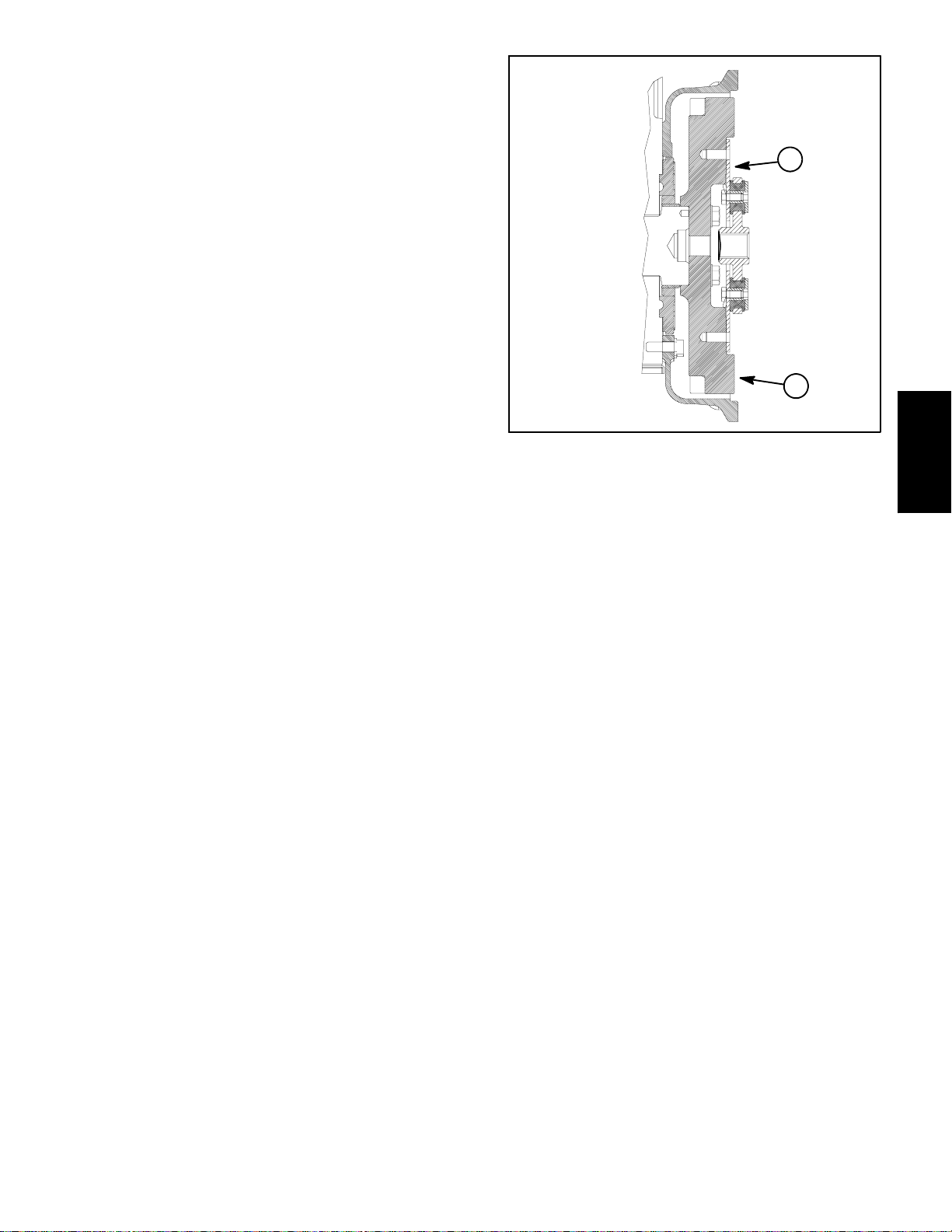
12.Remove transport cylinder assembly from engine
mount (Fig. 16). It is not necessary to remove the hydraulichose from thecylinder.Locateandremove cylinder spacer from between transport cylinder and engine
mount.
13.On Groundsmaster 4010--D machines:
1. Lock nut
2. Throttle cable
3. Cable support
4. Lock nut
5. Washer head screw
6. Cap screw (2 used)
4
Figure 14
7. Cable clamp
8. Spring washer (2 used)
9. Lock nut
10. Cable swivel
11. Cable stop
6
3
10
4
11
1
9
7
5
2
3
8
6
A. Removewindshield washer reservoir from reservoir mount on engine (Fig. 17). Position reservoir
away from engine. Do not remove reservoir mount
from engine.
B. Removeair conditioningcompressorfrombrackets (see Air Conditioning Compressor Removal in
theServiceandRepairssectionofChapter9 --Operator Cab). Position compressor away from engine
taking care to not damage compressor or hoses.
Support compressor to make sure it willnot fall during engine removal.
C. Disconnect coolant hose from fitting on engine
water flange.
1
1. Fan
2. Fan motor bracket
3. Fan motor
5
2
Figure 15
4. Cap screw (6 used)
5. Flange nut (6 used)
6. Radiator
Groundsmaster 4000--D/4010--DPage 3 -- 14Kubota Diesel Engine
Page 33

15.Make sure all cable ties securingthewiringharness,
fuellines or hydraulic hoses to the engine are removed.
16.Connect hoist or lift to the lift tabs on engine.
17.Remove flange nuts, rebound washers and cap
screws securing the engine mounts to the engine supports.
RIGHT
FRONT
12
11
10
13
3
14
1
CAUTION
One person should operate lift or hoist while
another person guides the engine out of the machine.
IMPORTANT: Make sure not to damage the engine,
fuel and hydraulic lines, electrical harness or other
components while removing the engine.
18.Carefully remove engine assembly from machine.
19.Ifnecessary,removeengine mountsfromthe engine
using Figure 10 as a guide.
Engine Installation (Fig. 10)
1. Make sure that all parts removed from the engine
duringmaintenance or rebuilding are installedtotheengine.
2. Ifremoved, installenginemounts totheengine using
Figure 10 as a guide.
3. Connect hoist or lift to the engine lift tabs.
CAUTION
9
15
16
Figure 16
1. Carriage screw (2 used)
2. Cylinder spacer
3. Transport cylinder
4. Lock nut (2 used)
5. Piston
6. Backup ring (2 used)
7. O--ring (2 used)
8. Retaining ring
6
3
7
6
7
8
9. Seal
10. O--ring
11. Fitting
12. O--ring
13. Hydraulic hose
14. RH engine mount
15. Jam nut
16. Cap screw
2
4
5
Kubota
Diesel Engine
2
1
4
5
One person should operate lift or hoist while
another person guides the engine into the machine.
IMPORTANT: Make sure not to damage the engine,
fuel and hydraulic lines, electrical harness or other
parts while installing the engine.
4. Carefully lower engine into the machine.
Figure 17
5. Align engine to the engine supports and hydraulic
pumpinputshaft.Secureenginetoenginesupportswith
cap screws, rebound washers and flange nuts.
1. Reservoir
2. Mount
3. Carriage screw (3 used)
4. Washer (3 used)
5. Nut (3 used)
6. Flange head screw
7. Exhaust mount
6. Secure hydraulic pump assembly to engine (see
Pump Assembly Installation in the Service and Repairs
section of Chapter 4 -- Hydraulic System).
Groundsmaster 4000--D/4010--D Page 3 -- 15 Kubota Diesel Engine
Page 34

7. Install fan motor and fan assembly (Fig. 15).
A. Carefullypositionfanmotor,fanand motorbrack-
et assembly to radiator.
13.Connect wires and/or electrical connections to the
following electrical components:
A. The temperature sender and alternator (Fig 11).
B. Secure fan motor bracket to radiator with six (6)
cap screws and flange nuts.
C. Remove caps and plugs placed in hoses and fittings during removal to prevent contamination.
D. Connect hydraulic hoses to cooling fan motor
(see Hydraulic Hose and Tube Installation in the
GeneralInformationsectionofChapter4 -- Hydraulic
System).
8. Positionupperradiator shroud and coolant reservoir
withbrackettotheradiator.Secureshroudandreservoir
bracket to the radiator and lower radiator bracket with
removedfasteners (seeRadiatorInstallationin this section).Make sure thatclearancebetweenshroud and fan
is at least 0.180” (4.6 mm) at all points.
9. Connectthrottlecabletoinjectorpump(Figs.13and
14):
A. Secure throttle cable swivel to speed control le-
ver with lock nut.
B. Place throttle cable under cable clamp.
C. Adjust throttle cable position in cable clamp so
that engine governor lever contacts the high speed
stop bolt at the same time that the throttle lever contacts the end of the slot in the control console.
D. Tighten cable clamp to secure throttle cable.
B. The glow plug (Fig. 12).
C. The engine run solenoid.
D. Battery,frameandwireharness groundtotheen-
gine block.
E. The starter and low oil pressure switch (near
starter).
F. The air conditioning compressor (Groundsmas-
ter 4010--D machines).
14.Install aircleanerassembly totheengine (seeAirFilter System Installation in this section).
15.Installexhaustsystemtomachine(seeExhaustSystem Installation in this section).
16.Connect coolant hosestotheradiator.Makesureradiator drain is shut. Fill radiator and reservoir with coolant.
17.Check position of wires, fuel lines, hydraulic hoses
andcables for proper clearance with rotating, high temperature and moving components.
18.Install battery tomachine (see Battery Service in the
Service and Repairs section of Chapter 5 -- Electrical
System). Make sure to connect positive battery cable
first and then negative battery cable. Secure battery to
machine with strap and cover.
10.Connect fuel line to the injection pump (Fig. 13).
11.Installtransportcylinder assembly to engineadapter
plate (Fig. 16). Make sure that cylinder spacer is positioned between transport cylinder and engine mount.
12.On Groundsmaster 4010--D machines:
A. Position windshield washer reservoir to bracket
onengine (Fig. 17). Secure with removed fasteners.
B. Install air conditioning compressor to brackets
(see Air Conditioning Compressor Installation in the
Serviceand Repairs section of Chapter9 -- Operator
Cab).Makesurethatdrivebeltisproperly tensioned.
C. Connect coolant hose to fitting on engine water
flange.
19.Check and adjust engine oil as needed.
20.Check and adjust hydraulic oil as needed.
21.Bleed fuel system.
22.Start engine and operate hydraulic controls to properlyfill hydraulic system(see Charge Hydraulic System
in the Service and Repairs section of Chapter 4 -- Hydraulic System).
23.Close and secure hood.
Groundsmaster 4000--D/4010--DPage 3 -- 16Kubota Diesel Engine
Page 35

This page is intentionally blank.
Kubota
Diesel Engine
Groundsmaster 4000--D/4010--D Page 3 -- 17 Kubota Diesel Engine
Page 36

Spring Coupler
RIGHT
FRONT
21
20
19
18
17
13
14
15
16
23
22
1. Spring coupler
2. Washer (14 used)
3. Cap screw (6 used)
4. Flywheel plate
5. Cap screw (4 used)
6. LH engine mount
7. Cap screw (2 used)
8. Carriage screw (2 used)
9. Cylinder spacer
10
12
11
1
2
3
4
Loctite #242
29 to 33 ft--lb
(40to44N--m)
2
9
24
5
25
6
8
7
Loctite #242
28 to 32 ft--lb
(38to43N--m)
Figure 18
10. Transport cylinder
11. Lock nut (2 used)
12. Cylinder piston
13. O--ring (2 used)
14. Backup ring (2 used)
15. Retaining ring
16. Seal
17. O--ring
18. Hydraulic fitting
19. O--ring
20. Hydraulic hose
21. RH engine mount
22. Cap screw
23. Jam nut
24. Lock washer (2 used)
25. Cap screw (2 used)
Groundsmaster 4000--D/4010--DPage 3 -- 18Kubota Diesel Engine
Page 37
Coupler Removal (Fig. 18)
NOTE: The hydraulic pump assembly needs to be re-
moved from engine before coupler can be removed.
1. Ifengineis in machine, support enginefrombelowto
prevent it from shifting. Remove the following:
A. Removehydraulicpumpassembly frommachine
(seePiston (Traction) Pump Removal in the Service
and Repairs section of Chapter 4 -- Hydraulic System).
B. Removetransportcylinderassemblyfromengine
mount. It is not necessary to remove the hydraulic
hose from the cylinder. Locate and remove cylinder
spacer from between transport cylinder and engine
mount.
2. Remove flywheel plate and spring coupler from engine using Figure 18 as a guide.
Coupler Installation (Fig. 18)
1. Position spring coupler to engine flywheel and align
mounting holes. Make sure that coupling hub is away
from engine flywheel (Fig. 19).
Engine Side Hydraulic
Pump Side
1
2
Figure 19
1. Coupler 2. Engine flywheel
Kubota
Diesel Engine
2. Apply Loctite #242 (or equivalent) to threads of cap
screws (item 3). Secure coupler to flywheel with six (6)
capscrews and washers. Torquecapscrewsin a crossing pattern from 29 to 33 ft--lb (40 to 44 N--m) .
3. Apply Loctite #242 (or equivalent) to threads of cap
screws (items 5 and 7) used to secure flywheel plate to
engine. Position flywheel plate to engine and engine
mounts. Secure flywheel plate and mounts with cap
screws (items 5 and 7) and washers using a crossing
pattern tightening procedure. Torque cap screws in a
crossing pattern from 28 to 32 ft--lb (38 to 43 N-- m).
4. If engine is in machine, install the following:
A. Install transport cylinder assembly to engine
mount. Make sure that cylinder spacer is placed between transport cylinder and engine mount. Check
transport cylinder adjustment (see Transport Cylinderin the ServiceandRepairssection of Chapter 4 -Hydraulic System).
B. Installhydraulic pump assembly tomachine(see
Piston (Traction) Pump Installation in the Service
and Repairs section of Chapter 4 -- Hydraulic System).
Groundsmaster 4000--D/4010--D Page 3 -- 19 Kubota Diesel Engine
Page 38

This page is intentionally blank.
Groundsmaster 4000--D/4010--DPage 3 -- 20Kubota Diesel Engine
Page 39

Table of Contents
Chapter 4
Hydraulic System
SPECIFICATIONS 2............................
GENERAL INFORMATION 3.....................
Operator’s Manual 3..........................
Check Hydraulic Fluid 3.......................
Towing Traction Unit 3.........................
Relieving Hydraulic System Pressure 4..........
Traction Circuit Component Failure 4............
Hydraulic Hoses 5............................
Hydraulic Hose and Tube Installation 6..........
Hydraulic Fitting Installation 7..................
HYDRAULIC SCHEMATIC 9.....................
HYDRAULIC FLOW DIAGRAMS 10...............
Traction Circuit: Low Speed (4WD) 10...........
Traction Circuit: Hi Speed (2WD) 12.............
Lower Cutting Deck 14........................
Raise Cutting Deck 16.........................
Mow 18......................................
Mow Circuit Cutting Deck Blade Braking 20......
Steering Circuit 22............................
Engine Cooling Fan Circuit 24..................
SPECIAL TOOLS 26............................
TROUBLESHOOTING 30........................
TESTING 36...................................
Traction Circuit Charge Pressure 38.............
Traction Circuit Relief Pressure 40..............
Counterbalance Pressure 42...................
Traction Circuit Reducing Valve (PR) Pressure 44.
Rear Traction Circuit (RV) Relief Pressure 46.....
Piston (Traction) Pump Flow 48.................
Cutting Deck Circuit Pressure 50................
PTO Relief Pressure 52........................
Cutting Deck Motor Case Drain Leakage 54......
Cutting Deck Gear Pump Flow 56...............
Lift/Lower Circuit Relief Pressure 58.............
Steering Circuit Relief Pressure 60..............
Steering Cylinder Internal Leakage 62...........
Steering and Lift/Lower Gear Pump Flow 64......
Engine Cooling Fan Circuit 66..................
Engine Cooling Fan Circuit Gear Pump Flow 68..
ADJUSTMENTS 70.............................
Traction Linkage Adjustment 70.................
SERVICE AND REPAIRS 72.....................
General Precautions for Removing and
Installing Hydraulic System Components 72....
Check Hydraulic Lines and Hoses 72............
Flush Hydraulic System 73.....................
Filtering Closed--Loop Traction Circuit 74........
Charge Hydraulic System 75...................
Hydraulic Reservoir 76........................
Hydraulic Oil Cooler 78........................
Gear Pump 80.....
Gear Pump Service 82........................
Traction Circuit 84............................
Transport Cylinder 85.........................
Piston (Traction) Pump 86.....................
Piston (Traction) Pump Service 88..............
Rear Axle Motor 90...........................
Front Wheel Motor 92.........................
Rear Axle and Front Wheel Motor Service 94.....
4WD Manifold 96.............................
4WD Manifold Service 98......................
Traction (Flow Divider) Manifold 100.............
Traction (Flow Divider) M anifold Service 102.....
Filter Manifold 104............................
Filter Manifold Service 106.....................
Steering and Engine Cooling Fan Circuits 108....
Steering Control Valve 110.....................
Steering Control Valve Service 112..............
Steering Cylinder 114.........................
Steering Cylinder Service 116..................
Engine Cooling Fan Motor 118..................
Engine Cooling Fan Motor Service 120..........
Fan Drive Manifold 124........................
Fan Drive Manifold Service 126.................
PTO Circuit 128...............................
Cutting Deck Motor 129........................
Cutting Deck Motor Service 130................
PTO Manifold 134.............................
PTO Manifold Service 136.....................
Cutting Deck Lift/Lower Circuit 138..............
Lift/Lower Manifold 140........................
Lift/Lower Manifold Service 142.................
Side Deck Lift Cylinder 144.....................
Front Deck Lift Cylinder 146....................
Lift Cylinder Service 148.......................
EA TON MODEL 72400 SERVO CONTROLLED
PISTON PUMP REPAIR INFORMATION
EATON MODEL 74318 and 74348 PISTON MOTORS:
FIXED DISPLACEMENT, VALVE PLATE DESIGN
REPAIR INFORMATION
.......
....................
System
Hydraulic
Rev. AGroundsmaster 4000--D/4010--D Hydraulic SystemPage 4 -- 1
Page 40

Specifications
Item Description
Piston (Traction) Pump Eaton Variable Displacement Piston Pump
Maximum Displacement (per revolution) 2.48 in
System Relief Pressure: Forward 4000 PSI (274 bar)
System Relief Pressure: Reverse 5000PSI (343 bar)
Charge Pressure 250 PSI (17 bar)
Front Wheel Motors Eaton Fixed Displacement Piston Motors
Displacement (per revolution) 2.48 in
Rear Axle Motor Eaton Fixed Displacement Piston Motor
Displacement (per revolution) 2.01 in
Gear Pump Casappa 4 Section, Positive Displacement Gear pump
Section P1/P2 Displacement (per revolution) 1.16 in
Section P3/P4 Displacement (per revolution) 0.56 in
Steering Control Valve Eaton Steering Unit, Series 5
Displacement (per revolution) 6.1 in
Steering Circuit Relief Pressure 1350 PSI (93 bar)
Lift/Lower Circuit Relief Pressure 1600 PSI (110bar)
Cutting Deck Motors Sauer Danfoss Gear Motor
Displacement (per revolution) 1.17 in
(Model 72400)
3
(40.6 cc)
(Model 74318)
3
(40.6 cc)
(Model 74315)
3
(32.9 cc)
3
(19.09 cc)
3
(9.16 cc)
3
(100 cc)
3
(19.2 cc)
PTO Circuit Relief Pressure
Front and Left Side 3000 PSI (207 bar)
Right Side 2000 PSI (137 bar)
Engine Cooling Fan Motor Casappa Gear Motor
Displacement (per revolution) 0.50 in
Engine Cooling Fan Circuit Relief Pressure 3000 PSI (207 bar)
Hydraulic Filters Spin--on Cartridge Type
In--line Suction Strainer 100 Mesh (In Reservoir)
Hydraulic Reservoir 8 U.S. Gallons (30.3 Liters)
Hydraulic Oil See Operator’s Manual
3
(8.3 cc)
Groundsmaster 4000--D/4010--DHydraulic System Page 4 -- 2
Page 41

General Information
Operator’s Manual
The Operator’s Manual provides information regarding
the operation, general maintenance and maintenance
intervalsfor yourGroundsmastermachine.Refer tothat
publicationfor additional informationwhenservicingthe
machine.
Check Hydraulic Fluid
TheGroundsmasterhydraulicsystemisdesignedtooperate on anti--wear hydraulic fluid. The hydraulic reservoir located beneath the operator seat holds
approximately 8 U.S. gallons (30.3 liters) of hydraulic
fluid. Check level of hydraulic fluid daily. See Operator’s Manual for fluid level checking procedure and oil
recommendations.
2
1
Towing Traction Unit
IMPORTANT: If towing limits are exceeded, severe
damage to the piston (traction) pump may occur.
If it becomes necessary to tow (or push) the machine,
tow (or push) in a forward direction only and at a
speedbelow 3 mph (5 kph). Thepiston(traction)pump
isequippedwith aby--passvalvethatneedstobeturned
o
(one quarter turn) for towing. Refer to your Opera-
90
tor’s Manual for additional towing instructions.
IMPORTANT: Do not turn by--pass valve when en gine is running.
Figure 1
1. Hydraulic reservoir cap 2. Operator seat
1
2
Figure 2
1. Bypass valve location 2. Operator seat
System
Hydraulic
Groundsmaster 4000--D/4010--D Hydraulic SystemPage 4 -- 3
Page 42

Relieving Hydraulic System Pressure
Beforedisconnectingor performing any work onthehydraulic system, all pressure in the hydraulic system
mustberelieved.Parkmachineonalevelsurface,make
sure that PTO switch is OFF, lower cutting decks fully,
stopengine and engage parking brake.Waitfor all moving parts to come to a complete stop.
To relieve hydraulic pressure in traction circuit, move
tractionpedal to both forward and reverse directions. To
relieve hydraulic pressure in steering circuit, rotate
steering wheel in both directions.
Traction Circuit Component Failure
The traction circuit on Groundsmaster 4000--D and
4010--Dmachines is a closedloop system that includes
the piston (traction) pump, two (2) front wheel motors
and the rear axle motor. If a component in the traction
circuit should fail, debris and contamination from the
failed component will circulate throughout the traction
circuit. This contamination can damage other components in the circuit so it must be removed to prevent
additional component failure.
The recommended method of removing traction circuit
contamination would be to temporarily install the Toro
high flow hydraulic filter (see Special Toolsin this chapter) into the circuit. This filter should be used when connecting hydraulic test gauges in order to test traction
circuitcomponentsorafter replacingafailedtractioncircuit component (e.g. traction (piston) pump or wheel
motor). The filter will ensure that contaminates are removedfromthe closedloopandthus,donotcauseadditional component damage.
To relieve hydraulic pressure in lift circuit, start engine
andfully lowerthecuttingdecks.Turnkeyswitch toOFF
and remove key from the ignition switch.
System pressure in mow circuit is relieved when the
PTO switch is disengaged.
Once the Toro high flow hydraulic filter kit has been
placedin the circuit, raise andsupport the machine with
all wheels off the ground. Then, operate the traction circuit to allow oil flow throughout the circuit.The filter will
remove contamination from the traction circuit during
operation. Because the Toro high flow filter is bi--directional,the tractioncircuitcan be operatedinboththe forward and reverse direction. The filter should be
removed from the machine after contamination has
been removed from the traction circuit. See Filtering
Closed--LoopTractionCircuitintheServiceandRepairs
section of this chapter for additional information on using the Toro high flow hydraulic filter.
Thealternative tousingthe Torohigh flowhydraulicfilter
kit after a traction circuit component failure would be to
disassemble, drain and thoroughly clean all components, tubes and hoses in the traction circuit. If any debris remains in the traction circuit and the machine is
operated,thedebriscancauseadditionalcircuitcomponent failure.
Groundsmaster 4000--D/4010--DHydraulic System Page 4 -- 4
Page 43

Hydraulic Hoses
Hydraulichoses are subject to extremeconditions such
aspressuredifferentialsduring operationandexposure
to weather, sun, chemicals, very warm storage conditionsormishandlingduring operationandmaintenance.
These conditions can cause hose damage and deterioration. Some hoses are more susceptible to these
conditions than others. Inspect all machine hydraulic
hoses frequently for signs of deterioration or damage:
WARNING
Beforedisconnectingorperformingany work on
hydraulic system, relieve all pressure in system
(seeRelievingHydraulicSystemPressure in this
section).
Hard, cracked, cut, abraded, charred, leaking or
otherwise damaged hose.
Kinked, crushed, flattened or twisted hose.
Blistered, soft, degraded or loose hose cover.
Cracked, damaged or badly corroded hose fittings.
When replacing a hydraulic hose, be sure that the hose
is straight (not twisted) before tightening the fittings.
This can be done by observing the imprint (layline) on
the hose. Use two wrenches when tightening a hose;
hold the hose straight with one wrench and tighten the
hose swivel nut onto the fitting with the second wrench
(see Hydraulic Hose and Tube Installation in this section). If the hose has an elbow at one end, tighten the
swivel nut on that end before tightening the nut on the
straight end of the hose.
For additional hydraulic hose information, refer to Toro
Service Training Book, Hydraulic Hose Servicing (Part
Number 94813SL).
Keepbodyand handsaway frompinholeleaksor
nozzles that eject hydraulic fluid under high
pressure. Use paper or cardboard, not hands, to
search for leaks. Hydraulic fluid escaping under
pressure can have sufficient force to penetrate
the skin and cause serious injury. If fluid is injected into the skin, it must be surgically removed within a few hours by a doctor familiar
withthis typeofinjury.Gangrenemayresult from
such an injury.
System
Hydraulic
Groundsmaster 4000--D/4010--D Hydraulic SystemPage 4 -- 5
Page 44

Hydraulic Hose and Tube Installation (O--Ring Face Seal Fitting)
1. Makesurethreadsandsealingsurfacesofthehose/
tube and the fitting are free of burrs, nicks, scratches or
any foreign material.
2. Asapreventativemeasureagainstleakage,itis recommended that the face seal O--ring be replaced any
time the connection is opened. Make sure the O--ringis
installedandproperly seatedinthefittinggroove.Lightly
lubricate the O--ring with clean hydraulic oil.
3. Place the hose/tube against the fitting body so that
theflatfaceofthehose/tube sleevefullycontactstheO-ring in the fitting.
4. Thread the swivel nut onto the fitting by hand. While
holding the hose/tube with a wrench, use a torque
wrench to tighten the swivel nut to the recommended
installation torque shown in Figure 5. This tightening
process will require the use of an offset wrench (e.g.
crowfoot wrench). Use of an offset wrench will affect
torque wrench calibration due to the effective length
change of the torque wrench. Tightening torque when
usingatorquewrenchwithanoffsetwrenchwillbelower
than the listed installation torque (see Using a Torque
Wrench with an Offset Wrench in the Torque Specificationssection of Chapter 2 -- Product Records and Maintenance).
C. Useasecondwrench totightenthenut tothecorrect Flats From Wrench Resistance (F.F.W.R.). The
markingsonthe nutandfittingbodywillverifythatthe
connection has been properly tightened.
Siz e F.F.W.R.
4 (1/4 in. nominal hose or tubing) 1/2 to 3/4
6 (3/8 in.) 1/2 to 3/4
8 (1/2 in.) 1/2 to 3/4
10 (5/8 in.) 1/2 to 3/4
12 (3/4 in.) 1/3 to 1/2
16 (1 in.) 1/3 to 1/2
Swivel Nut
Tube or Hose
O--ring
Fitting Body
Figure 3
5. If a torque wrench is not available or if space at the
swivelnut prevents use of a torquewrench,analternate
method of assembly is the Flats From Wrench Resist-
Mark Nut
and Fitting
Body
Final
Position
ance (F.F.W.R.) method (Fig. 2).
A. Usingawrench,tighten the swivelnutonto thefittinguntillightwrench resistanceisreached (approximately 30 in--lb).
B. Mark the swivel nut and fitting body. Hold the
hose/tube with a wrench to prevent it from turning.
AT WRENCH RESISTANCE
Extend Line
Figure 4
Fitting Dash Size Hose/Tube Side Thread Size Installation Torque
4 9/16 -- 18 18to22ft--lb(25to29N--m)
6 11/16 - - 16 27to33ft--lb(37to44N--m)
8 13/16 -- 16 37to47ft--lb(51to63N--m)
10 1--14 60 to 74 ft--lb (82 to 100 N--m)
12 13/16--12 85 to 105 ft--lb (116 to 142 N--m)
16 17/16--12 110 to 136 ft--lb (150 to 184 N--m)
Initial
Position
AFTER TIGHTENING
20 1 11/16 -- 12 140 to 172 ft--lb (190 to 233 N--m)
Figure 5
Groundsmaster 4000--D/4010--DHydraulic System Page 4 -- 6
Page 45

Hydraulic Fitting Installation (SAE Straight Thread O--Ring Fitting into Component Port)
Non--Adjustable Fitting (Fig. 6)
1. Make sure all threads and sealing surfaces of fitting
and component port are free of burrs, nicks, scratches
or any foreign material.
2. Asapreventativemeasureagainstleakage,itis recommended that the O--ring be replaced any time the
connection is opened.
3. Lightly lubricate the O--ring with clean hydraulic oil.
Fittingthreadsshouldbecleanwith nolubricantapplied.
IMPORTANT: Before installing fitting into port, determine port material. If fitting is to be installed into
an aluminum port, installation torque is reduced.
4. Install the fitting into the port. Then, use a torque
wrench and socket to tighten the fitting to the recommended installation torque shown in Figure 7.
NOTE: Useof an offset wrench (e.g. crowfoot wrench)
will affect torque wrench calibration due to the effective
length change of the torque wrench. Tightening torque
when using a torque wrench with an offset wrench will
be less than the recommended installation torque. See
Using a Torque Wrench with an Offset Wrench in the
Torque Specifications section of Chapter 2 -- Product
Recordsand Maintenancetodetermine necessary conversion information.
5. If a torque wrench is not available, or if space at the
portpreventsuseof atorquewrench, analternatemethod of assembly is the Flats From Finger Tight (F.F.F.T.)
method.
A. Install the fitting into the port and tighten it down
full length until finger tight.
B. If port material is steel, tighten the fitting to the
listed F.F.F.T. If port material is aluminum, tighten fitting to 60% of listed F.F.F.T.
Siz e F.F.F.T.
4 (1/4 in. nominal hose or tubing) 1.00 +
6(3/8in.) 1.50+
8(1/2in.) 1.50+
10 (5/8 in.) 1.50 +
12 (3/4 in.) 1.50 +
16 (1 in.) 1.50 +
Fitting
O--ring
0.25
0.25
0.25
0.25
0.25
0.25
Figure 6
System
Hydraulic
Fitting
Dash Size
Fitting Port Side
Thread Size
Installation Torque Into
Steel Port
Installation Torque Into
Aluminum Port
4 7/16 -- 20 15to19ft--lb(21to25N--m) 9to11ft--lb(13to15N--m)
5 1/2 -- 20 18to22ft--lb(25to29N--m) 11to15ft--lb(15to20N--m)
6 9/16 -- 18 34to42ft--lb(47to56N--m) 20to26ft--lb(28to35N--m)
8 3/4 -- 16 58to72ft--lb(79to97N--m) 35to43ft--lb(48to58N--m)
10 7/8 -- 14 99 to 121 ft--lb (135 to 164 N--m) 60 to 74 ft--lb (82 to 100 N--m)
12 11/16--12 134 to 164 ft--lb (182 to 222 N--m) 81 to 99 ft--lb (110 to 134 N--m)
14 13/16--12 160 to 196 ft--lb (217 to 265 N--m) 96 to 118 ft--lb (131 to 160 N--m)
16 15/16--12 202 to 248 ft--lb (274 to 336 N--m) 121 to 149 ft--lb (165 to 202 N--m)
20 15/8--12 247 to 303 ft--lb (335 to 410 N--m) 149 to 183 ft--lb (202 to 248 N--m)
Figure 7
Groundsmaster 4000--D/4010--D Hydraulic SystemPage 4 -- 7
Page 46

Adjustable Fitting (Fig. 8)
1. Make sure all threads and sealing surfaces of fitting
and component port are free of burrs, nicks, scratches
or any foreign material.
2. Asapreventativemeasureagainstleakage,itis recommended that the O--ring be replaced any time the
connection is opened.
3. Lightly lubricate the O--ring with clean hydraulic oil.
Fittingthreadsshouldbecleanwith nolubricantapplied.
4. Turnback the lock nut as far as possible. Make sure
the back up washer is not loose andis pushed up as far
as possible (Step 1 in Figure 9).
IMPORTANT: Before installing fitting into port, determine port material. If fitting is to be installed into
an aluminum port, installation torque is reduced.
Lock Nut
Back--up Washer
O--ring
Figure 8
5. Install the fitting into the port and tighten finger tight
until the washer contacts the face of the port (Step 2 in
Figure 9). Make sure that the fitting does not bottom in
the port during installation.
6. Toputthe fitting in the desired position, unscrew it by
the required amount to align fitting with incoming hose
or tube, but no more than one full turn (Step 3 in Figure
9).
7. Hold the fitting in the desired position with a wrench
and use a torque wrench to tighten the lock nut to the
recommended installation torque shown in Figure 7.
This tightening process will require the use of an offset
wrench (e.g. crowfoot wrench). Use of an offset wrench
will affect torque wrench calibration due to the effective
length change of the torque wrench. Tightening torque
when using a torque wrench with an offset wrench will
be lower than the listed installation torque (see Using a
Torque Wrench with an Offset Wrench in the Torque
Specifications section of Chapter 2 -- Product Records
and Maintenance).
8. If a torque wrench is not available, or if space at the
portpreventsuseof atorquewrench, analternatemethod of assembly is the Flats From Finger Tight (F.F.F.T.)
method. Hold the fitting in the desired position with a
wrench and, if port material is steel, tighten the lock nut
witha second wrench tothe listed F.F.F.T (Step 4 in Figure9).If port material is aluminum, tighten fittingto60%
of listed F.F.F.T.
Step 3Step 1
Step 2 Step 4
Figure 9
Siz e F.F.F.T.
4 (1/4 in. nominal hose or tubing) 1.00 +
6(3/8in.) 1.50+
8(1/2in.) 1.50+
10 (5/8 in.) 1.50 +
12 (3/4 in.) 1.50 +
16 (1 in.) 1.50 +
0.25
0.25
0.25
0.25
0.25
0.25
Groundsmaster 4000--D/4010--DHydraulic System Page 4 -- 8
Page 47

Hydraulic Schematic
4WD
MANIFOLD
MANIFOLD
TRACTION
FILTER
MANIFOLD
VALVE
BYPASS
S8
S9
.070
S6
.035
S5 S7
S4
S2 S3
RV2
S1
RV1
MANIFOLD
LIFT/LOWER
MANIFOLD
FAN DRIVE
TP1 P2
M1 M2 ST L
System
Hydraulic
MANIFOLD
FRONT PTO
NOTE: A larger hydraulic schematic is
included in Chapter 10: Foldout Drawings
LH PTO
MANIFOLD
RH PTO
MANIFOLD
Rev. AGroundsmaster 4000--D/4010--D Hydraulic SystemPage 4 -- 9
Page 48

Hydraulic Flow Diagrams
4WD
MANIFOLD
MANIFOLD
TRACTION
FILTER
MANIFOLD
VALVE
BYPASS
S8
S9
.035
.070
S5 S7
S6
S4
S2 S3
RV2
S1
RV1
MANIFOLD
LIFT/LOWER
MANIFOLD
FAN DRIVE
TP1 P2
M1 M2 ST L
Working Pressure
Low Pressure (Charge)
Traction Circuit: Low Speed (4WD) (Forward Shown)
Flow
Return or Suction
MANIFOLD
FRONT PTO
LH PTO
MANIFOLD
RH PTO
MANIFOLD
Rev. A Groundsmaster 4000--D/4010--DHydraulic System Page 4 -- 10
Page 49

Traction Circuit: Low Speed (4WD)
The traction circuit piston pump is a variable displacement pump that is directly coupled to the engine flywheel. Pushing the traction pedal engages a hydraulic
servo valve which controls the variable displacement
piston pump swash plate to create a flow of oil. This oil
isdirected tothefrontwheel andrearaxle motors.Operating pressure on the high pressure side of the closed
traction circuitloop is determined by the amountof load
developedatthefixed displacementwheel andaxlemotors. As the load increases, circuit pressure can increase to relief valve settings: 4000 PSI (274 bar) in
forward and 5000 PSI (343 bar) in reverse. If pressure
exceeds the relief setting, oil flows through the piston
pump relief valve to the low pressure side of the closed
loop traction circuit. The traction circuit provides operation in either Hi speed (2WD) or Low speed (4WD).
Traction circuit pressure (forward and reverse) can be
measured at test ports in hydraulic tubes. The forward
tractionport is on theleftside of themachineand the reverse traction port is on the right side of the machine.
The traction circuit pump and motors use a small
amount of hydraulic fluid for internal lubrication. Fluid is
designed to leak across traction pump and motor components into the case drain. This leakage results in the
lossof hydraulic fluid from the closedlooptractioncircuit
that must be replaced. The charge circuit is designedto
replace this traction circuit leakage.
The gear pump section that supplies oil to the steering
and lift/lower circuits also provides oil for the charge circuit. This gear pump is driven directly off the traction
pump. It provides a constant supply of charge oil to
make up for oil that is lost due to internal leakage in the
traction pump and motors.
Pump flow for the charge circuit is directed through the
oil filter and to t he low pressure side of the closed loop
traction circuit. A filter bypass valve allows charge oil
flow to the closed loop if the filter becomes plugged.
Chargepressureislimitedto250PSI(17bar)by a relief
valve located in the oil filter manifold. Charge pressure
canbemeasuredat the charge circuit pressure test port
on the oil filter manifold.
Forward Direction
Whenthe Hi/LowswitchisintheLow speed(4WD)positionandthetractionpedalispushedin theforwarddirection, oil from the piston pump passes through the
tractionmanifold.Oil flow from traction manifold portM1
drives the front wheel motors in the forward direction
and then returns to the piston pump. Oil flow from tractionmanifoldport M2 is routed tothe P1 port of the 4WD
manifoldwhereitisdirectedtothePD1cartridgeandout
ofthemanifoldtodrivetherearaxlemotorintheforward
direction.Oil returningfromtherearmotorre--entersthe
4WD manifold at the M2 port. Flow passes through the
PD2cartridge,throughthe CVcheckvalve, outmanifold
port P2 and back to the piston pump.
When going down a hill, the tractor becomes an over-running load that drives the wheel and axle motors. In
this condition, the rear axle motor could lock up as the
oil pumped from the motor increases pressure as it returns to the piston pump. To prevent rear wheel lock up,
an adjustable relief valve (RV) in the 4WD manifold reduces rear axle motor pressure created in down hill, dynamic braking conditions.
Reverse Direction
The traction circuit operates essentially the same in reverse Low speed (4WD) as it does in the forward direction. However, the flow through the circuit is reversed.
Oil flow from the piston pump is directed to the front
wheel motors and also to the 4WD manifold. The oil to
the front wheel motors drives them in the reverse direction and then returns to the piston pump through the
tractionmanifold. Theoilto the 4WDmanifoldentersthe
manifoldat portP2andflows through pressurereducing
valve(PR) which limits thedown stream pressure tothe
rear axle motor to 650 PSI (45 bar) so the rear wheels
will not scuff the turf during reverse operation. This reducedpressure flows throughthePD2cartridge and out
port M2 to the rear axle motor. Return oil from the rear
motor re--enters the 4WD manifold at port M1, flows
throughthePD1cartridge,exitsthemanifoldatportP1
and returns to the piston pump.
System
Hydraulic
Aflow divider is incorporated intothe traction circuit and
is located in the traction manifold. When in Low speed
(4WD), the operator can momentarily engage this flow
divider when low traction situations could lead to wheel
spin. Depressing the flow divider switch energizes the
solenoid valve in the traction manifold. This energized
solenoid valve causes traction pump hydraulic flow to
split between the front wheel motors (approximately
45%) and rear axle motor (approximately 55%) to reduce the chance that excessive circuit flow goes to a
spinning wheel.
Groundsmaster 4000--D/4010--D Hydraulic SystemPage 4 -- 11
Page 50

4WD
SHIFTED)
(PD1 ANDPD2
MANIFOLD
(EXTENDED)
(ENERGIZED)
MANIFOLD
TRACTION
FILTER
MANIFOLD
VALVE
BYPASS
S8
S9
.070
.035
S6
S5 S7
S4
S2 S3
RV2
S1
RV1
MANIFOLD
LIFT/LOWER
MANIFOLD
FAN DRIVE
TP1 P2
M1 M2 ST L
Working Pressure
Low Pressure (Charge)
Traction Circuit: Hi Speed (2WD) (Forward Shown)
Flow
Return or Suction
MANIFOLD
FRONT PTO
LH PTO
MANIFOLD
RH PTO
MANIFOLD
Rev. A Groundsmaster 4000-- D/4010--DHydraulic System Page 4 -- 12
Page 51

Traction Circuit: Hi Speed (2WD)
The traction circuit piston pump is a variable displacement pump that is directly coupled to the engine flywheel. Pushing the traction pedal engages a hydraulic
servo valve which controls the variable displacement
piston pump swash plate to create a flow of oil. This oil
isdirected tothefrontwheel andrearaxle motors.Operating pressure on the high pressure side of the closed
traction circuitloop is determined by the amountof load
developedatthefixed displacementwheel andaxlemotors. As the load increases, circuit pressure can increase to relief valve settings: 4000 PSI (274 bar) in
forward and 5000 PSI (343 bar) in reverse. If pressure
exceeds the relief setting, oil flows through the piston
pump relief valve to the low pressure side of the closed
loop traction circuit. The traction circuit provides operation in either Hi speed (2WD) or Low speed (4WD).
Traction circuit pressure (forward and reverse) can be
measured at test ports in hydraulic tubes. The forward
tractionport is on theleftside of themachineand the reverse traction port is on the right side of the machine.
The traction circuit pump and motors use a small
amount of hydraulic fluid for internal lubrication. Fluid is
designed to leak across traction pump and motor components into the case drain. This leakage results in the
lossof hydraulic fluid from the closedlooptractioncircuit
that must be replaced. The charge circuit is designedto
replace this traction circuit leakage.
Forward Direction
With the Hi/Low speed switch in the Hi speed position
(2WD),solenoid valve(SV)inthe4WD manifold is energized. The solenoid valve spool shifts to direct charge
pressure that shifts the PD1 and PD2 control valve
spools.TheshiftedPD1valvepreventspistonpumphydraulicflow from reaching the rear axlemotor.With flow
blocked to the rear axle motor, all traction pump flow is
directedtothe frontwheelmotorsto allowahighertransport speed in the forward direction.
Without flow to the rear axle motor, the rotating rear
wheels drive the axle m otor so it acts like a pump. Inlet
oilto the axle motor is provided by a check valve that allowscharge circuit oil into the rear axlemotor circuit. Oil
leaving the axle motor enters the 4WD manifold at port
M2 and is directed back to the axle motor through the
shiftedPD1 cartridge and manifold port M1. To allow for
rear wheel loop cooling when in forward transport operation, a small amount of oil exits through the shifted
PD1 and PD2 cartridges that returns to the reservoir.
This oil loss is replaced by charge circuit oil.
A transport cylinder is included in the traction circuit to
reduce traction control arm movement on the piston
pump when operating in Hi speed (2WD). This reduced
armmovement limits swash plate rotation to preventexcessive transport speed.
System
Hydraulic
The gear pump section that supplies oil to the steering
and lift/lower circuits also provides charge oil for the
traction circuit. This gear pump is driven directly off the
tractionpump.Itprovidesaconstantsupplyofcharge oil
to the traction circuit to make up for oil that is lost due to
internal leakage in the traction pump and motors.
Chargepumpflow is directed through theoilfilter and to
the low pressure side of the closed loop traction circuit.
A filter bypass valve allows charge oil flow to the closed
loopifthe filter becomes plugged. Charge pressure is limited to 250 PSI (17bar) by a relief valve located in the
oil filter manifold. Charge pressure can be measured at
the charge circuit pressure test port on the oil filter manifold.
Thetraction manifold flow divider cannot beengagedby
the operator during Hi speed (2WD) operation.
Reverse Direction
The traction circuit operates essentially the same in reverseHispeed(2WD)asitdoesintheforwarddirection.
However, the flow through the circuit is reversed. The
shifted solenoid valve (SV) and directional valves PD1
andPD2inthe4WD manifold prevent oil flow to the rear
axlemotor.Oil flow from the pistonpumpis therefore directed to only the front wheel motors. This oil drives the
front wheel motors in the reverse direction and then returnsto the piston pump.Oil circulation through the rear
axlemotorloop isthe sameas intheHispeed(2WD)forward direction.
Groundsmaster 4000--D/4010--D Hydraulic SystemPage 4 -- 13
Page 52

4WD
MANIFOLD
MANIFOLD
TRACTION
FILTER
MANIFOLD
VALVE
RETRACTING
BYPASS
S8
S9
.070
.035
S6
S5 S7
S4
S2 S3
RV2
S1
RV1
ENERGIZED
SOLENIDS S1, S3 AND S4
MANIFOLD
LIFT/LOWER
MANIFOLD
FAN DRIVE
TP1 P2
M1 M2 ST L
Working Pressure
Low Pressure (Charge)
Lower Cutting Deck (LH Deck Shown)
Flow
Return or Suction
MANIFOLD
FRONT PTO
LH PTO
MANIFOLD
RH PTO
MANIFOLD
Rev. A Groundsmaster 4000-- D/4010--DHydraulic System Page 4 -- 14
Page 53

Lower Cutting Deck
A four section gear pump is coupled to the piston (traction) pump. The third gear pump section supplies hydraulic flow to both the steering and lift/lower circuits.
Hydraulicflow from this pump section is delivered to the
two circuits through aproportional flow divider that is located in the fan drive manifold. This flow divider splits
pump flow approximately 50% for the steering circuit
and 50% for the lift/lower circuit.
Arelief valve (RV1) located inthe lift/lower manifold limits lift/lower circuit pressure to 1600 PSI (110 bar). An
adjustable valve (RV2) in the lift/lower manifold maintains back pressure (counterbalance) on the deck lift
cylinders to allow some of the cutting deck weight to be
transferred to the traction unit to improve traction.
Each of the cutting decks (center, right and left) can be
loweredindependentlywiththeuse ofthree(3)switches
on the armrest console. Pressing the front of a switch
provides an input f or the TEC--5001 controller to lower
acutting deck. The controller provideselectricaloutputs
to solenoids in the lift/lower manifold to allow appropriate manifold valve shift to cause a deck t o lower.
When the cutting decks are in a stationary position, all
solenoids in the lift/lower manifold are de--energized. In
this position, lift/lower circuit flow bypasses the lift cylindersand isdirectedthroughthe lift/lower manifold,oilf ilter and then to the traction charge circuit.
NOTE: To lower a cutting deck, the operatormust be in
the operator seat and the traction speed must be in the
Low speed (4WD) position.
Lower Center Cutting Deck
To lower the center cutting deck, the front of the center
console switch is depressed. The switch signal is an input to the TEC--5001controller which provides an electrical output to solenoid valve S6 in the lift/lower
manifold. Energized solenoid valve S6 shifts to allow a
passage for oil flow from the rod end of the center deck
lift cylinders. The weight of the cutting deck causes the
center deck lift cylinders to extend and lower the center
cutting deck. Oil from the extending cylinders flows
throughan orifice in the fitting at manifold port C2(.070)
tocontrol thedropspeedofthecuttingdeck.Flowisthen
directedthrough the shifted S6, valveRV2, out manifold
port CH, to the oil filter and is then availablefor the traction charge circuit.
Whenthe center deck switch is released, solenoid S6 is
de--energized and the lift cylinders and center cutting
deck are held in position.
Lower Right Cutting Deck
Tolowertherightwingdeck,thefrontoftherightconsole
switchis pushed asaninput to the TEC--5001 controller.
The controller provides an electrical output to solenoid
valvesS1,S8andS9in thelift/lowermanifold.Theenergized solenoid valves shift to allow a passage for circuit
oil flow to the rod end of the right deck lift cylinder.
ShiftedS1 prevents oil flowfrom bypassing the liftcylinders. Shifted S8 allows an oil path to the rod end of the
right lift cylinder to retract the lift cylinder and lower the
right cutting deck. Oil from the retracting cylinder flows
through the orifice in manifold port C6 (.063) to control
thedrop speed of the cutting deck. Flowis then directed
through shifted S9, valve RV2, out manifold port CH, to
the oil filter and then to the traction charge circuit.
When the deck switch is released, the manifold solenoids are de--energized and the lift cylinder and right
cutting deck are held in position.
Lower Left Cutting Deck
To lower the left wing deck, the front of the left console
switchis pushed asaninput to the TEC--5001 controller.
The controller provides an electrical output to solenoid
valvesS1,S3andS4in thelift/lowermanifold.Theenergized solenoid valves shift to allow a passage for circuit
oilflow to the rod end of the left decklift cylinder.Shifted
S1 prevents oil flow from bypassing the lift cylinders.
Shifted S3 allows an oil path to the rod end of the left lift
cylinder to retract the lift cylinder and lower the left cutting deck. Oil from the retracting cylinder flows through
the orifice in manifold port C4 (.063) to control the drop
speed of the cutting deck. Flow is then directed through
the shifted S4, valve RV2, out manifold port CH, to the
oil filter and then to the traction charge circuit.
When the deck switch is released, the manifold solenoids are de--energizedand the lift cylinder and left cutting deck are held in position.
Cutting Deck Float
Cutting deck float allows the fully lowered cutting decks
to follow ground surface contours. Lift/lower manifold
solenoid valves S4 (left deck), S6 (center deck) and S9
(right deck) are energized when the decks are fully lowered.Theseenergizedsolenoidsprovidean oilpassage
toand from the liftcylinders to allow cylinderand cutting
deck movement while mowing. Counterbalance pressure (RV2) will affect deck float operation.
NOTE: If a deck is already fully lowered when the ignition switch is moved from OFF to RUN, the deck will not
be in float until the appropriate deck lift/lower switch is
momentarily pressed to lower.
System
Hydraulic
Rev. AGroundsmaster 4000--D/4010--D Hydraulic SystemPage 4 -- 15
Page 54
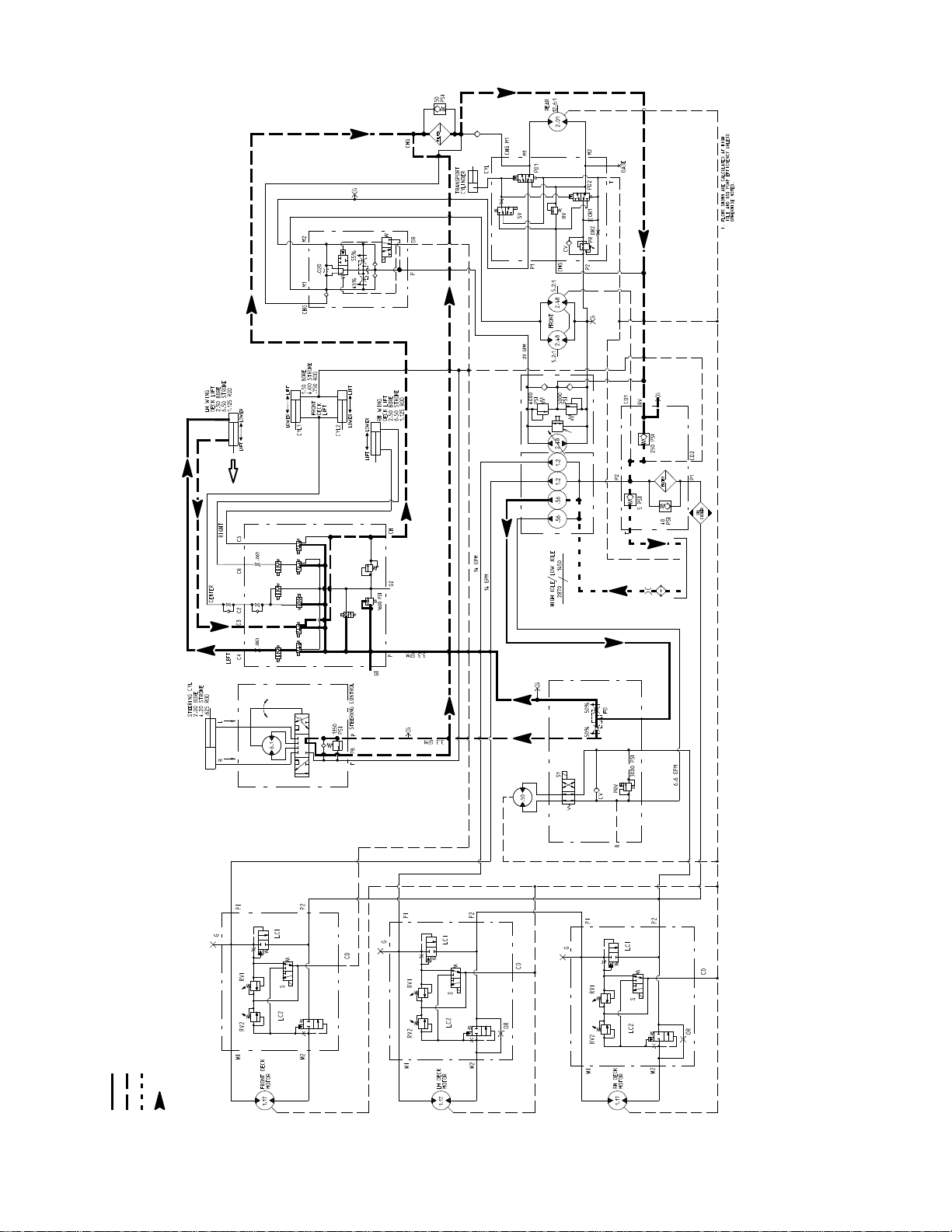
4WD
MANIFOLD
MANIFOLD
TRACTION
FILTER
MANIFOLD
VALVE
EXTENDING
BYPASS
S8
S9
.070
.035
S6
S5 S7
S4
S2 S3
RV2
S1
RV1
ENERGIZED
SOLENIDS S1AND S2
MANIFOLD
LIFT/LOWER
MANIFOLD
FAN DRIVE
TP1 P2
M1 M2 ST L
Working Pressure
Low Pressure (Charge)
Raise Cutting Deck (LH Deck Shown)
Flow
Return or Suction
MANIFOLD
FRONT PTO
LH PTO
MANIFOLD
RH PTO
MANIFOLD
Rev. A Groundsmaster 4000-- D/4010--DHydraulic System Page 4 -- 16
Page 55

Raise Cutting Deck
A four section gear pump is coupled to the piston (traction) pump. The third gear pump section supplies hydraulic flow to both the steering and lift/lower circuits.
Hydraulicflow from this pump section is delivered to the
two circuits through aproportional flow divider that is located in the fan drive manifold. This flow divider splits
pump flow approximately 50% for the steering circuit
and 50% for the lift/lower circuit.
Arelief valve (RV1) located inthe lift/lower manifold limits lift/lower circuit pressure to 1600 PSI (110 bar). An
adjustable valve (RV2) in the lift/lower manifold maintains back pressure (counterbalance) on the deck lift
cylinders to allow some of the cutting deck weight to be
transferred to the traction unit to improve traction.
Each of the cutting decks (center, right and left) can be
raised independently with the use of three (3) switches
on the armrest console. Pressing the rear of a switch
provides an input for the TEC--5001 controller to raise a
cutting deck. The controller provides electrical outputs
to solenoids in the lift/lower manifold to allow appropriatevalveshifttocauseadecktoraise.
When the cutting decks are in a stationary position, all
solenoids in the lift/lower manifold are de--energized. In
this position, lift/lower circuit flow bypasses the lift cylindersand isdirectedthroughthe lift/lower manifold,oilf ilter and is then available for the traction charge circuit.
NOTE: To raise a cutting deck, the operator must be in
the operator seat.
Raise Center Cutting Deck
To raise the center cutting deck, the rear of the center
console switch is depressed. The switch signal is an input to the TEC--5001controller which provides an electricaloutput tosolenoidvalvesS1 and S5 in the lift/lower
manifold. The energized solenoid valves shift to allow a
passage for circuit oil flow to the rod end of the center
deck lift cylinders. Shifted S1 prevents oil flow from bypassing the lift cylinders.Shifted S5 allowsan oil path to
therodend of the front lift cylinders causing theliftcylinders to retract and raise the center cutting deck. An orifice in manifold port C2 (.035) exists to control the raise
speed of the cutting deck. Oil from the barrel end of the
retracting cylinders returns to the hydraulic reservoir.
Raise Right Cutting Deck
To raise the right deck, the rear of the right console
switch is depressed as an input to the TEC-- 5001 controller.The controller provides an electrical output to solenoid valves S1 and S7 in the lift/lower manifold. The
energized solenoid valves shift to allow a passage for
circuitoil flow to the barrel end of the right deck lift cylinder. Shifted S1 prevents oil flow from bypassing the lift
cylinders. Shifted S7 allows an oil path through the orifice in manifold port C6 and to the barrel end of the right
lift cylinder to extend the lift cylinder and raise the right
cutting deck. Oil from the extending cylinder is directed
throughS8(de--energized),out manifold port CH, to the
oil filter and then to the traction charge circuit.
When the deck switch is released, the manifold solenoids are de--energized and the lift cylinder and right
cutting deck are held in position.
Raise Left Cutting Deck
To raise the left deck, the rear of the left console switch
is depressed as an input to the TEC--5001 controller.
The controller provides an electrical output to solenoid
valves S1 and S2 in the lift/lower manifold. The energized solenoid valves shift to allow a passage for circuit
oil flow to the barrel end of the left deck lift cylinder.
ShiftedS1 prevents oil flowfrom bypassing the liftcylinders. Shifted S2 allows an oil path through the orifice in
manifoldport C4 and to the barrel end of theleft liftcylinder to extend the lift cylinder and raise the left cutting
deck.Oilfrom the extending cylinder is directed through
S3 (de-- e nergized), out manifold port CH, to the oil filter
and then to the traction charge circuit.
When the deck switch is released, the manifold solenoids are de--energizedand the lift cylinder and left cutting deck are held in position.
System
Hydraulic
When the deck switch is released, the manifold solenoids are de--energized and the center deck lift cylinders and center cutting deck are held in position.
Rev. AGroundsmaster 4000--D/4010--D Hydraulic SystemPage 4 -- 17
Page 56

4WD
MANIFOLD
MANIFOLD
TRACTION
FILTER
MANIFOLD
VALVE
BYPASS
S8
S9
.070
.035
S6
S5 S7
S4
S2 S3
RV2
S1
RV1
MANIFOLD
LIFT/LOWER
MANIFOLD
FAN DRIVE
TP1 P2
M1 M2 ST L
Working Pressure
Low Pressure (Charge)
Mow (Front Deck Shown)
Flow
Return or Suction
MANIFOLD
FRONT PTO
LH PTO
MANIFOLD
RH PTO
MANIFOLD
Rev. A Groundsmaster 4000-- D/4010--DHydraulic System Page 4 -- 18
Page 57

Mow
A four section gear pump is coupled to the piston (traction)pump. Hydraulic flowforthemowcircuitis supplied
by two sections of the gear pump. The gear pump section closest to the piston (traction) pump supplies hydraulicflow to the side cuttingdecks, while thenext gear
pump section supplies the front cutting deck.
Each cutting deck is controlled by a hydraulic manifold
equipped with a solenoid control valve (S), bypass cartridge(LC1),brakecartridge(LC2)andtwo(2)reliefcartridges (RV1 and RV2). Circuit pressure can be
measured at port (G) of the hydraulic manifold for each
cutting deck.
NOTE: To engage the mow circuit, the operator must
be in the operator seat, the cutting deck(s)must be fully
loweredandthetractionspeedmustbeintheLow
speed (4WD) position.
PTO Not Engaged
WhenthePTOswitch is OFF or if the deck is raised with
thePTOswitch ON,thePTOmanifoldsolenoidvalve(S)
is not energized and the solenoid spool is in the neutral
position. This solenoid spool in neutral allows a small
amountofhydraulicflow toreturnto tankthroughamanifoldsensinglinewhichcauses a pressure increase that
shifts bypass cartridge LC1. The pump flow is routed
throughshiftedLC1andoutmanifoldportP2. Brakecartridge LC2 remains in the unshifted position to prevent
any return flow from the deck motor to keep the motor
from rotating.
Deck motor case drain leakage returns to the hydraulic
reservoir.
PTO Circuit Relief
Maximum mow circuit pressure is limited for each deck
by a relief valve (RV1) in the PTO manifold. The center
and leftdeck relief valves are setat 3000 PSI (207bar)
and the right deck relief valve is set at 2000 PSI (138
bar).
Relief valve (RV1) and bypass cartridge (LC1) work together as a two stage relief. When increased circuit resistance is met or if a cutting blade should strike an
object, the pressure increase is felt at the relief valve. If
the pressure should exceed the relief valve setting, the
reliefvalve will open,creatinga small amount of hydraulic flow to return to tank through a manifold sensing line.
This flow causes a pressure increase that shifts bypass
cartridgeLC1anddiverts circuitflowawayfromthe deck
motor to manifold port P2 (Fig. 10). When circuit pressure lowers, relief valve (RV1) closes which returns bypass cartridge LC1 back to its neutral position allowing
flow to return to the deck motor.
System
Hydraulic
PUMP FLOW
Return flow from the front and right PTO manifolds is
routedthroughtheoilcooler,oilfilterandthentothe gear
pump input. Return flow from the left PTO manifold provides supply for the right deck.
PTO Engaged
When the PTO switch is turned ON and the decks are
lowered, the PTO manifold solenoid valve (S) is energized by the TEC--5001controller. This shifted solenoid
valve prevents any sense line flow through the valve
whichallowsthebypasscartridgeLC1tobe initsneutral
position.Gear pump flow enteringthemanifoldisrouted
out manifoldport M1 and to the cutting deckmotor. The
return flow from the deck motor re--entersmanifold port
M2. The shifted solenoid valve (S) allows a small
amount of this return flow to return to tank through a
manifoldsensing line which causes a pressureincrease
that shifts brake cartridge LC2. Hydraulic flow is routed
through shifted LC2, out manifold port P2, through the
oil cooler and filter and then is routed to the gear pump
input. The deck motor continues to rotate as long as solenoid valve (S) is energized.
FRONT PTO
MANIFOLD
Figure 10
SOLENOIDS ENERGIZED
DECK MOTOR STALLED
RV1 SHIFTED
LC1 SHIFTED
RETURN
Groundsmaster 4000--D/4010--D Hydraulic SystemPage 4 -- 19
Page 58

Mow Circuit Cutting Deck Blade Braking
WhentheoperatorturnsthePTOswitchOFF orifadeck
is raised with the PTO switch ON, PTO manifold solenoidvalve(S)isde--energizedcausingbypass cartridge
(LC1) to shift (refer to information in Mow Circuit in this
section).This shifted cartridge allowsoilreturnoutmanifold port P2. At the same time, solenoid valve (S) in its
neutralpositionpreventsanysenseline flowthrough the
spool which causes the brake cartridge (LC2) to shift to
its neutral position blocking return flow from the deck
motor and slowing the cutting blades (Fig. 11).
Theinertiaoftherotating cuttingblades,however,effectively turns the deck motor into a pump causing an increasein pressure as the flow from the motor comesup
against the closed brake cartridge (LC2). When this
pressurebuilds to approximately 600 PSI (41 bar), relief
valve (RV2) opens which allows a small amount of hydraulic flow to return to tank through a manifold sensing
line (Fig. 12). This flow causes a pressure increase that
shifts brake cartridge (LC2) to once again allow oil flow
from the motor (Fig. 13). When return pressure drops
below 600 PSI (41 bar), relief valve (RV2) reseats and
causes LC2 to close again blocking return flow from the
deckmotortofurtherslowthecutting blades.Thisaction
ofthebrake relief valve opening and the brake cartridge
shifting occurs several times in a very short time frame
as the blades finally come to a stop. Once the blades
have stopped, brake cartridge LC2 remains in the neutral position to keep the deck motor from rotating.
PTO
MANIFOLD
PUMP FLOW
RETURN
Figure 11
PUMP FLOW
PTO
MANIFOLD
PTO
MANIFOLD
RETURN
Figure 12
PUMP FLOW
RETURN
Figure 13
Groundsmaster 4000--D/4010--DHydraulic System Page 4 -- 20
Page 59

This page is intentionally blank.
System
Hydraulic
Groundsmaster 4000--D/4010--D Hydraulic SystemPage 4 -- 21
Page 60

4WD
MANIFOLD
MANIFOLD
TRACTION
FILTER
MANIFOLD
VALVE
BYPASS
S8
S9
.035
.070
RETRACTING
S6
S5 S7
S4
S2 S3
RV2
S1
RV1
MANIFOLD
LIFT/LOWER
MANIFOLD
FAN DRIVE
TP1 P2
M1 M2 ST L
Working Pressure
Steering Circuit (Left Turn Shown)
Low Pressure (Charge)
Return or Suction
Flow
MANIFOLD
FRONT PTO
LH PTO
MANIFOLD
RH PTO
MANIFOLD
Rev. A Groundsmaster 4000-- D/4010--DHydraulic System Page 4 -- 22
Page 61

Steering Circuit
A four section gear pump is coupled to the piston (traction) pump. The third gear pump section supplies hydraulic flow to both the steering and lift/lower circuits.
Hydraulicflow from this pump section is delivered to the
two circuits through aproportional flow divider that is located in the fan drive manifold. This flow divider splits
pump flow approximately 50% for the steering circuit
and 50% for the lift/lower circuit.
Steering circuit pressure is limited to 1350 PSI (93 bar)
bya relief valvelocatedin the steeringcontrolvalve. Circuit pressure can be measured at a test port in the hydraulic supply tube.
With the steering wheel in the neutral position and the
engine running, flow entersthe steering control valve at
the P port and goes through the steering control spool
valve, by--passing the rotary meter (V1) and steering
cylinder. Flow leaves the control valve through the PB
port to the oil filter and traction charge circuit.
Left Turn
When a left turn is made with the engine running, the
turningofthesteeringwheelpositionsthespool valve so
thatflowgoesthroughthetop ofthespool.Flowentering
the steering control valveat the P port goes through the
spool and is routed to two places. First,most of the flow
throughthevalveisby--passedoutthePBportbackto
the oil filter and traction charge circuit. Second, the remainder of the flow is drawn through the rotary meter
(V1) and out the L port. Pressure retracts the steering
cylinder piston for a left turn. The rotary meter ensures
that the oil flow to the cylinder is proportional to the
amount of the turning on the steering wheel. Fluid leaving the cylinder flows back through the spool valve then
through the T port and to the hydraulic reservoir.
Thesteeringcontrolvalvereturns to the neutral position
when turning is completed.
Right Turn
When a right turn is made with the engine running, the
turningofthesteering wheelpositionsthespoolvalveso
that flow goes throughthe bottom of the spool. Flow entering the steering control valve at the P port goes
throughthe spool and is routed to two places. As in a left
turn,most of the flow throughthevalveisby--passedout
the PB port back to the oil filter and traction charge circuit. Also like a left turn, the remainder of the flow is
drawn through rotary meter (V1) but goes out port R.
Pressure extends the steeringcylinder piston fora right
turn.The rotarymeter ensures that the oil flow to the cylinder is proportional to the amount of the turning on the
steering wheel. Fluid leaving the cylinder flows back
through the spool valve then through the T port and to
the hydraulic reservoir.
Thesteeringcontrolvalvereturns to the neutral position
when turning is completed.
System
Hydraulic
STEERING CYLINDER
NO PISTON MOVEMENT
R
T
NEUTRAL POSITION
L
1350
PSI
PB
P
STEERING
CONTROL
STEERINGCYLINDER
PISTON MOVEMENT
R
T
LEFT TURN
L
1350
PSI
PB
P
STEERING
CONTROL
Figure 14
Groundsmaster 4000--D/4010--D Hydraulic SystemPage 4 -- 23
STEERING CYLINDER
PISTONMOVEMENT
R
T
RIGHT TURN
L
1350
PSI
PB
P
STEERING
CONTROL
Page 62

4WD
MANIFOLD
MANIFOLD
TRACTION
FILTER
MANIFOLD
VALVE
BYPASS
S8
S9
.035
.070
S6
S5 S7
S4
S2 S3
RV2
S1
RV1
MANIFOLD
LIFT/LOWER
MANIFOLD
FAN DRIVE
TP1 P2
M1 M2 ST L
Working Pressure
Low Pressure (Charge)
Engine Cooling Fan Circuit (Forward Direction Shown)
Flow
Return or Suction
MANIFOLD
FRONT PTO
LH PTO
MANIFOLD
RH PTO
MANIFOLD
Rev. A Groundsmaster 4000-- D/4010--DHydraulic System Page 4 -- 24
Page 63

Engine Cooling Fan Circuit
A four section gear pump is coupled to the piston (traction)pump. Thegearpump sectionfarthestfrom thepiston pump supplies hydraulic flow for the engine cooling
fan circuit (Fig. 15).
The fan drive manifold controls the operation of the hydraulic motor that drives the engine cooling fan in addition to including the flow divider for the steering and
lift/lower circuits. The fan drive manifold controls the
speedand direction of the fanmotor based on electrical
output from the TEC--5002 controller.
Oil flow from the gear pump to the cooling fan motor is
controlled by the proportional relief valve (PRV) in the
fan drive manifold. This valve adjusts fan circuit pressure and flow based on a PWM (Pulse Width Modulation)signalfromtheTEC--5002controller.Thecontroller
uses engine coolant and hydraulic oil temperatures as
inputstodeterminetheproperPWMsignalfor the(PRV)
valve. The fan circuit flow determines the speed of the
coolingfan motor and thus, the speed ofthecoolingfan.
If the fan motor is stalled for any reason, the manifold
proportionalreliefvalve(PRV) hasasecondary function
as a circuit relief to limit fan motor pressure to 3000 PSI
(207 bar).
When the engine is shut off, the over--running inertia
load of the fan blades keeps driving the fan motor and
turnsitintoapump.Thecheckvalve(CV)inthefandrive
manifold will open to keep the motor circuit full of oil so
the fan motor will not cavitate.
Forward Direction Fan Operation
Oilflowfromthe gearpumpis sentthroughthede--energizedfanmanifoldsolenoid valve(S1)torotate thecooling fan motor.Return flow from the motor re--entersthe
manifold (port M2), through the de--energized solenoid
valve(S1), outofthe manifold (portT)andthen isrouted
through the oil cooler and oil filter.
ing oil flow to return to the fan motor but in the reverse
direction causing the motor and cooling fan to run in reverse. The controller determines the length of time that
thefan should be run in reverse before fan rotation is returned to the forward direction.
2
1
Figure 15
1. Gear pump 2. Fan drive manifold
REVERSE DIRECTION SHOWN
TO RESERVOIR
TO STEERING
CIRCUIT
M1 M2 L
(ENERGIZED)
TO LIFT/LOWER
CIRCUIT
System
Hydraulic
Reverse Direction Fan Operation (Fig. 16)
TheTEC--5002controller can reversethecooling fan to
clean debris from the rear intake screen. If hydraulic oil
and/or engine coolant temperatures increase to an unsuitable level, a high PWM signal is sent to the (PRV)
valve to slow the cooling fan and direct pump oil flow to
the reservoir. The controller then energizes solenoid
valve(S1)in thefandrivemanifoldtoreversecoolingfan
motoroil flow so that themotorrunsinthereversedirection.AlowerPWMsignalis sent to the PRV valve allow-
Groundsmaster 4000--D/4010--D Hydraulic SystemPage 4 -- 25
P1 P2T
TO OIL COOLER
Figure 16
FAN DRIVE
MANIFOLD
FROM GEAR PUMP
Page 64

Special Tools
Order special tools from your Toro Distributor.
Hydraulic Pressure Test Kit
Use to take various pressure readings for diagnostic
tests. Quick disconnect fittings provided attach directly
to mating fittings on machine test ports without tools. A
high pressure hose is provided for remote readings. Kit
contains one each: 1000 PSI (70 bar), 5000 PSI (350
bar) and 10000 PSI (700 bar) gauges. Use gauges as
recommended in the Testing section of this chapter.
Toro Part Number: TOR47009
15 GPM Hydraulic Tester Kit (Pressure and Flow)
Figure 17
Use to test hydraulic circuits and components for flow
andpressurecapacitiesas recommendedinthe Testing
sectionofthischapter.Thistesterincludes thefollowing:
1. INLET H OSE: Hose connected from the system circuit to the inlet side of the hydraulic tester.
2. LOAD VALVE: A simulated working load is created
in the circuit by turning the valve to restrict flow.
3. PRESSURE GAUGE: Glycerine filled 0 to 5000 PSI
gauge to provide operating circuit pressure.
4. FLOW METER: This meter measures actual oil flow
in the operating circuit with a gauge rated from 1 to 15
GPM(5to55LPM).
5. OUTLET HOSE: A hose from the outlet side of the
hydraulictesterconnectsto thehydraulicsystem circuit.
6. FITTINGS:An assortment of hydraulicfittingsareincluded with this kit.
Toro Part Number: TOR214678
Figure 18
Groundsmaster 4000--D/4010--DHydraulic System Page 4 -- 26
Page 65

40 GPM Hydraulic Tester (Pressure and Flow)
Use to test hydraulic circuits and components for flow
andpressurecapacitiesas recommendedinthe Testing
sectionofthischapter.Thistesterincludes thefollowing:
1. LOAD VALVE: A simulated working load is created
in the circuit by turning the valve to restrict flow.
2. PRESSURE GAUGE: Glycerine filled 0 to 5000 PSI
gauge to provide operating circuit pressure.
3. FLOW METER: This meter measures actual oil flow
in the operating circuit with a gauge rated from 4 to 40
GPM (20 to 150 LPM).
Toro Part Number: AT40002
NOTE: Thistesterdoesnotincludehoses(seeHydrau-
lic Hose Kit TOR6007 below).
Hydraulic Hose Kit
Thiskitincludesfittingsandhosesneededtoconnect40
GPM hydraulic tester (AT40002) or high flow hydraulic
filterkit(TOR6011)tomachinehydraulic tractionsystem
components.
Toro Part Number: TOR6007
Figure 19
Figure 20
System
Hydraulic
Groundsmaster 4000--D/4010--D Hydraulic SystemPage 4 -- 27
Page 66
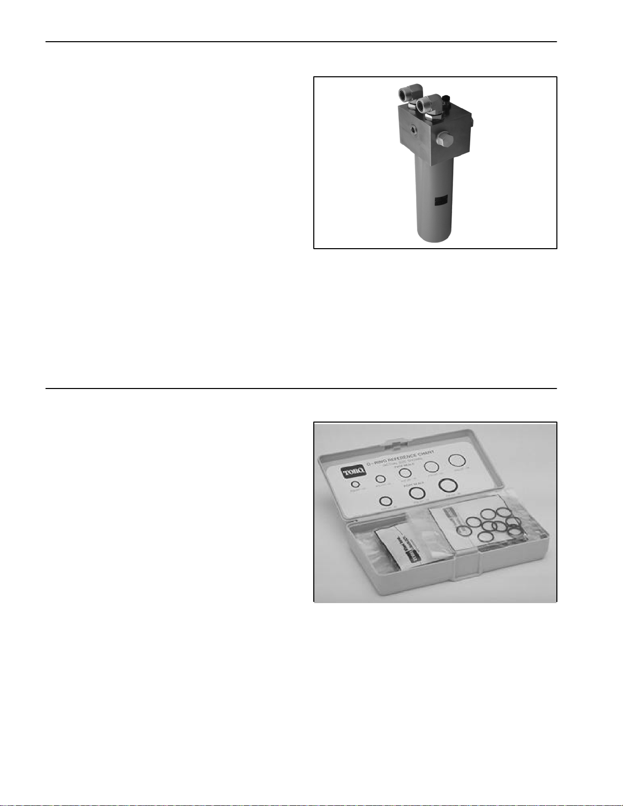
High Flow Hydraulic Filter Kit
The high flow hydraulic filter kit is designed with large
flow (40 GPM/150 LPM) and high pressure (5000
PSI/345 bar) capabilities. This kit provides for bi--directionalfiltration which prevents filtered debris from being
allowedback intothe circuit regardless of flow direction.
If a component failure occurs in the closed loop traction
circuit, contamination from the failed part will remain in
the circuit until removed. When connecting hydraulic
test gauges in order to test traction circuit components
orafterreplacing afailedtractioncircuitcomponent(e.g.
hydrostat or wheel motor), the high flow hydraulic filter
can be installed in the traction circuit. The filter will ensure that contaminates are removed from the closed
loopandthus,donotcause additional component damage.
Toro Part Number: TOR6011
NOTE: This kit does not include hoses (see Hydraulic
Hose Kit TOR6007 above).
NOTE: Replacementfilter element is Toro part number
TOR6012. Filter element cannister tightening torque is
25 ft--lb (34 N--m).
Figure 21
O --Ring Kit
The O--ring kit includes O--rings in a variety of sizes for
face seal and port seal hydraulic connections. It is recommended that O--rings be replaced whenever a hydraulic connection is loosened.
Toro Part Number: 117--2727
Figure 22
Groundsmaster 4000--D/4010--DHydraulic System Page 4 -- 28
Page 67

Hydraulic Test Fitting Kit
This kit includes avariety of O--ringFace Seal fittings to
enable you to connect test gauges into the system.
The kit includes: tee’s, unions, reducers, plugs, caps
and male test fittings.
Toro Part Number: TOR4079
Measuring Container
Use this container for doing hydraulic motor efficiency
testing(motors with case drain lines only).Measureefficiency of a hydraulic motor by restricting the outlet flow
from the motor and measuring leakage from the case
drainline while themotorispressurizedby the hydraulic
system.
The table in Figure 25 provides gallons per minute
(GPM)conversionformeasuredmilliliterorouncemotor
case drain leakage.
Toro Part Number: TOR4077
TORO TEST FITTING KIT (TOR4079)
Figure 23
System
Hydraulic
Figure 24
Figure 25
Groundsmaster 4000--D/4010--D Hydraulic SystemPage 4 -- 29
Page 68

Troubleshooting
The charts that follow contain suggestions that can be
used to assist in diagnosing hydraulic system performance issues. The suggestions are not all--inclusive.
Also, consider that there may be more than one cause
for a machine problem.
Review the hydraulic schematic and information on hydraulic system operation in the Hydraulic Flow Diagrams section of this Chapter. This information will be
useful during the hydraulic troubleshooting process.
Refer to the Testing section of this Chapter for precautions and specific hydraulic test procedures.
NOTE: When troubleshooting traction problems on
your Groundsmaster, if a problem exists in both Low
(4WD) and Hi (2WD) speeds, consider a faulty component that affects the entire traction circuit (e.g. charge
circuit, traction relief v alves, piston pump, front wheel
motors).Ifthe problem exists in Low (4WD) butnotinHi
(2WD), consider a problem in the 4WD traction system
(e.g. rear axle motor, 4WD manifold).
General Hydraulic System Problems
Problem Possible Cause
Hydraulic oil leaks from machine Fitting(s), hose(s) or tube(s) is (are) loose or damaged.
O--ring(s) or seal(s) is (are) missing or damaged.
Hydraulic system operates hot.
NOTE: An indication that the hy-
draulic system is operating at excessive temperatures would be frequent
reversing of the cooling fan and a
normal engine coolant temperature.
Engine RPM is too low.
Brakes are applied or sticking.
Hydraulic reservoir oil level is low.
Hydraulic oil is contaminated or the wrong type.
Piston pump by--pass valve is open or damaged.
Cooling system is not operating properly.
Charge pressure is low.
Traction circuit pressure is incorrect.
Pump(s) or motor(s) are damaged.
Hydraulic oil in reservoir foams. Hydraulic reservoir oil level is low.
Wrong type of oil is in the hydraulic system.
Air is leaking into a pump suction line.
Groundsmaster 4000--D/4010--DHydraulic System Page 4 -- 30
Page 69

Traction Circuit Problems
Problem Possible Cause
Machine operates in one direction
only.
Traction pedal is sluggish. Traction control linkage is stuck or binding.
Machine travels too far before stopping when the traction pedal is released.
Traction power is lost or machine will
not operate in either direction.
Traction control linkage is faulty.
Traction relief valve is faulty.
Charge pressure is low.
Piston (traction) pump servo control valve orifices are plugged or
damaged.
4WD manifold PD1 and PD2 pilot directional valves seals are leaking
or damaged.
Traction linkage is out of adjustment.
Traction pedal does not return to neutral position.
Charge pressure is low.
Piston (traction) pump servo control valve orifices are plugged or
damaged.
Hydraulic reservoir oil level is low.
Piston pump by--pass valve is open or damaged.
Charge pressure is low.
System
Hydraulic
Traction circuit pressure is low.
Front wheel motor couplers are damaged.
Four wheel drive will not engage.
NOTE: Low (4WD) will not engage
when the cutting decks are lowered.
Four wheel drive will not disengage. Electrical problem exists (see Chapter 5 -- Electrical System).
Electrical problem exists (see Chapter 5 -- Electrical System).
Solenoid valve (SV) in 4WD manifold is faulty.
Cartridge valve(s) in 4WD manifold is faulty.
Drive gear on rear axle motor or driven gear for rear axle is loose or
damaged.
Rear axle motor is damaged.
Solenoid valve (SV) in 4WD manifold is faulty.
Cartridge valve in 4WD manifold is damaged or sticking.
Groundsmaster 4000--D/4010--D Hydraulic SystemPage 4 -- 31
Page 70

Mow Circuit Problems
Problem Possible Cause
No cutting decks will operate.
NOTE: To engage the mow circuit,
the seat must be occupied, the cutting deck(s) must be fully lowered,
the traction speed must be in the
Low (4WD) position and the PTO
switch must be ON.
One cutting deck will not operate. Electrical problem exists (see Chapter 5 -- Electrical System).
All cutting decks operate slowly. Engine RPM is low.
Electrical problem exists (see Chapter 5 -- Electrical System).
Gear pump is damaged (NOTE: other hydraulic circuits impacted as
well).
System pressure to the affected deck is low.
Woodruff key on affected deck motor is damaged.
Solenoid valve (S) in PTO manifold for affected deck is faulty.
Cartridge valve in PTO manifold for affected deck is damaged or
sticking.
Deck motor or gear pump section is damaged.
NOTE: If appropriate, transfer a suspected damaged motor to
another cutting deck. If problem follows the motor, motor needs
repair or replacement.
Deck motor or gear pump sections are damaged.
Cutting deck stops under load. Relief valve in PTO manifold for affected deck is by--passing.
Deck motor has internal leakage (by-- passing oil).
Cutting deck gear pump section is worn or damaged.
Groundsmaster 4000--D/4010--DHydraulic System Page 4 -- 32
Page 71

Lift Circuit Problems
Problem Possible Cause
Cutting decks will not raise.
NOTE: Seat must be occupied in or-
der to raise cutting decks.
Cutting decks raise, but will not stay
up.
NOTE: Lift cylinders cannot provide
an absolutely perfect seal. The cutting deck will eventually lower if left
in the raised position during storage.
Cutting decks will not lower.
NOTE: To lower a cutting deck, the
seat must be occupied and the traction speed must be in the Low
(4WD) position.
Engine RPM is too low.
Hydraulic oil level in reservoir is low.
Solenoid valve (S1) in lift/lower manifold is faulty.
Electrical problem exists (see Chapter 5 -- Electrical System).
Lift arm pivots are binding.
Relief valve in lift/lower manifold is stuck.
Lift cylinder(s) is (are) damaged.
Gear pump section for lift circuit is inefficient (NOTE: steering circuit
impacted as well).
Lift circuit lines or fittings are leaking.
Lift cylinder is damaged.
Cartridge valve(s) in lift/lower manifold has damaged seals or is
faulty.
Lift arm pivots are binding.
Electrical problem exists (see Chapter 5 -- Electrical System).
Solenoid valve (S1) in lift/lower manifold is faulty.
Counterbalance pressure is excessive.
System
Hydraulic
Lift cylinder is damaged.
Groundsmaster 4000--D/4010--D Hydraulic SystemPage 4 -- 33
Page 72

Steering Circuit Problems
Problem Possible Cause
Steering inoperative or sluggish Steering components (e.g. tie rods, steering cylinder ends) are
worn or binding.
Steering cylinder is binding.
Oil level in hydraulic reservoir is low (NOTE: other hydraulic sys-
tems are affected as well).
Steering relief valve in steering control valve is stuck or damaged.
Steering cylinder leaks internally.
Steering control valve is worn or damaged.
Gear pump section is worn or damaged (NOTE: a worn or dam-
aged gear pump section will also affect the lift and traction (charge)
circuits).
Engine Cooling Fan Circuit Problems
Problem Possible Cause
Cooling fan runs only in forward direction (fan does not run in reverse
direction).
Cooling fan does not rotate. Fan motor is worn or damaged.
Cooling fan always rotates at slow
speed.
Cooling fan always rotates at fast
speed.
Fan control manifold solenoid cartridge valve (S1) is faulty.
Electrical problem exists that prevents fan control manifold solenoid
valve (S1) operation (see Chapter 5 -- Electrical System).
Gear pump section for engine cooling fan circuit is worn or damaged.
Fan control manifold cartridge valve seals are leaking.
Check valve in fan control manifold is not seating.
Fan control manifold proportional relief valve (PRV) is stuck open.
Hydraulic fan motor is worn or damaged.
Fan control manifold proportional relief valve (PRV) is faulty.
Electrical problem exists that prevents fan control manifold propor-
tional relief valve (PRV) operation (see Chapter 5 -- Electrical System).
Groundsmaster 4000--D/4010--DHydraulic System Page 4 -- 34
Page 73

This page is intentionally blank.
System
Hydraulic
Groundsmaster 4000--D/4010--D Hydraulic SystemPage 4 -- 35
Page 74
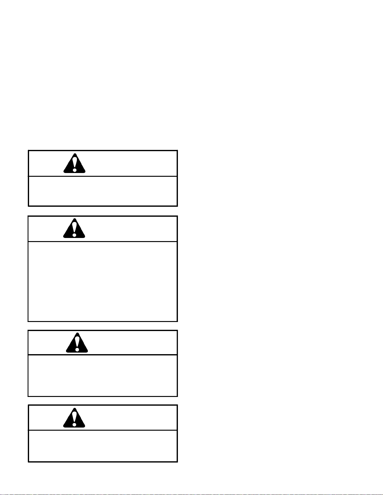
Testing
The most effective method for isolating problems in the
hydraulic system is by using hydraulic test equipment
suchaspressure gauges and flow metersin the circuits
during various operational checks (see the Special
Tools section in this Chapter).
Before Performing Hydraulic Tests
IMPORTANT: All obvious areas such as oil supply,
filter,binding linkages, loose fasteners or improper
adjustmentsmustbecheckedbeforeassuming that
ahydraulic componentis the sourceof theproblem.
Precautions for Hydraulic Testing
CAUTION
Failure to use gauges with recommended pressure (PSI/bar) rating as listed in test procedures
couldresult indamage to thegauge andpossible
personal injury from leaking hot oil.
1. Clean machine thoroughly before disconnecting or
disassemblingany hydraulic components. Always keep
in mind the need for cleanliness when working on hydraulic equipment. Contamination will cause excessive
wear of components.
2. Put metal caps or plugs on any hydraulic lines left
open or exposed during testing or removal of components.
3. Theenginemustbe ingoodoperatingcondition.Use
a phototac when performing a hydraulic test. Engine
speed can affect the accuracy of the tester readings.
Check actual speed of the pump when performing flow
testing.
4. When using the hydraulic tester with flow and pressure capabilities, the inlet and the outlet hoses must be
properly connected and not reversed to prevent damage to the hydraulic tester or components.
5. When using the hydraulic tester with flow and pressure capabilities, completely open flow control valve on
tester before starting the engine to minimize the possibility of damaging components.
WARNING
Keepbody and hands awayfrom pin hole leaksor
nozzlesthat eject hydraulic fluidunderhigh pressure. Do not use hands to search for leaks; use
paper or cardboard. Hydraulicfluid escaping under pressure can have sufficient force to penetrate the skin and cause serious injury. If fluid is
injected into the skin, it must be surgically removed within a few hours by a doctor familiar
withthistypeof injury.Gangrenemay result from
such an injury.
WARNING
Before disconnecting or performing any work
on the hydraulic system, all pressure in the system must be relieved. See Relieving Hydraulic
SystemPressureintheGeneralInformationsection in this chapter.
6. Install fittings finger tight and far enough to make
sure that they are not cross--threadedbefore tightening
them with a wrench.
7. Position tester hoses to prevent rotating machine
partsfrom contacting and damaging thehosesortester.
8. Check oil level in the hydraulic reservoir. After connecting test equipment, make sure tank is full.
9. Check control linkages for improper adjustment,
binding or broken parts.
10.After installing test gauges, run engine at low speed
and check for any hydraulic oil leaks.
11.All hydraulic tests should be made with thehydraulic
oil at normal operating temperature.
12.Before returningmachine to use, makesure that hydraulic reservoir has correct fluid level.
CAUTION
All testing should be performed by two (2)
people.One personshouldbe in theseat to operate the machine, and the second person should
read test instruments and record test results.
Groundsmaster 4000--D/4010--DHydraulic System Page 4 -- 36
Page 75

Which Hydraulic Tests Are Necessary?
Before beginning any hydraulic test, identify if the problemis related tothetractioncircuit, cutting(mow)circuit,
lift circuit, steering circuit or engine cooling fan circuit.
Once the faulty system has been identified, perform
tests that relate to that circuit.
1. If a traction circuit problem exists, consider performing one or more of the following tests: Traction Circuit
Charge Pressure, Traction Circuit Relief Pressure,
Counterbalance Pressure, Rear Traction Circuit (RV)
Relief Pressure, Traction Circuit Reducing Valve (PR)
Pressure and/or Piston (Traction) Pump Flow Tests.
IMPORTANT: Refer to Traction Circuit Component
Failure in the General Information section of this
chapterfor information regarding the importanceof
removing contamination from the traction circuit.
2. If a cutting (mow) circuit problem exists, consider
performing one or more of the following tests: Cutting
Deck Circuit Pressure, PTO Relief Pressure, Cutting
Deck Motor C ase Drain Leakage and/or Cutting Deck
Gear Pump Flow Tests.
3. If a lift circuit problem exists, consider performing
oneor more of thefollowing tests: Lift/Lower Circuit ReliefPressure and/or Steering and Lift/Lower Gear Pump
Flow Tests.
4. Ifa steering circuit problemexists,consider performing one or more of the following tests: Steering Circuit
Relief Pressure, Steering Cylinder Internal Leakage
and/or Steering and Lift/Lower Gear Pump Flow Tests.
5. Ifaenginecooling fan circuit problem exists, considerperforming one or moreof the following tests: Engine
Cooling Fan Circuit and/or Engine Cooling Fan Circuit
Gear Pump Flow Tests.
System
Hydraulic
Groundsmaster 4000--D/4010--D Hydraulic SystemPage 4 -- 37
Page 76

Traction Circuit Charge Pressure (Using Pressure Gauge)
FROM LIFT CONTROL
MANIFOLD
MANIFOLD
TRACTION
4WD
MANIFOLD
FROM FRONT DECK
CYLINDERS
FROM STEERING VALVEPORT PB
FROM STEERING VALVEPORT T
FROM FRONT PTO MANIFOLD
TO PTO (MOW) CIRCUIT
TO PTO (MOW) CIRCUIT
TO STEERING & LIFT CIRCUITS
TO COOLING FAN CIRCUIT
PRESSURE
GAUGE
FILTER
MANIFOLD
FROM PTO MANIFOLDS & FAN MOTOR
FROM PTO MANIFOLDS
Groundsmaster 4000--D/4010--DHydraulic System Page 4 -- 38
Page 77

ProcedureforTractionCircuitChargePressureTest
1. Make sure hydraulic oil is at normal operating temperature by operating the machine under load for
approximately ten (10) minutes. Make sure the hydraulic tank is full.
2. Park machine on a level surface with the cutting
decks lowered and off. Make sure engine is off and the
parking brake is applied.
3. Raise and support operator seat.
CAUTION
8. Next, with the pressure gauge still connected to the
charge pressure test port, take a gauge reading while
operating the machine in forward and reverse. Start the
engine and put throttle at high idle speed (2870 RPM).
Apply the brakes and push the traction pedal forward
while monitoring the pressure gauge. Repeat for reverse direction. Stop engine and record test results.
9. If charge pressure meets specifications under no
load conditions (step 5 above), but consistently drops
more than 15% when under traction load, the piston
(traction) pump and/or traction motor(s) should be suspected of wear and inefficiency. When the pump or motors are worn or damaged, the charge pump is not able
to keep up with internal leakage in the traction system
components.
Prevent personal injury and/or damage to equipment. Read all WARNINGS, CAUTIONS and Precautions for Hydraulic Testing at the beginning
of this section.
4. Connect a 1000 PSI (70 bar) pressure gauge onto
charge pressure test port on filter manifold (Fig. 26).
5. Start the engine and put throttle at high idle speed
(2870 RPM) with no load on the hydraulic system.
GAUGEREADINGTOBE200 to 300 PSI (13.8 to
20.6 bar).
6. Stop engine and record test results.
7. If there is no pressure or pressure is low, check for
restrictioninpumpintakeline.Also,inspectchargerelief
valve located in filter manifold (see Filter Manifold Service in the Service and Repairs section of this chapter).
A worn or damaged gear pump (P3) could also be considered (see Steering and Lift/Lower Gear Pump Flow
Test in this section).
NOTE: Ifgear pump (P3) is worn or damaged, charge,
steering and lift circuits will all be affected.
10.When testing is completed, disconnect pressure
gaugefromtestport.Lowerandsecureoperator’s seat.
1
2
Figure 26
1. Charge pressure port 2. Filter manifold
System
Hydraulic
Groundsmaster 4000--D/4010--D Hydraulic SystemPage 4 -- 39
Page 78

Traction Circuit Relief Pressure (Using Pressure Gauge)
FORWARD TRACTION CIRCUIT RELIEF PRESSURE TEST SHOWN
FROM LIFT CONTROL
MANIFOLD
PRESSURE
GAUGE
MANIFOLD
TRACTION
4WD
MANIFOLD
FROM FRONT DECK
CYLINDERS
FROM STEERING VALVEPORT PB
FROM STEERING VALVEPORT T
FROM FRONT PTO MANIFOLD
TO PTO (MOW) CIRCUIT
TO PTO (MOW) CIRCUIT
TO STEERING & LIFT CIRCUITS
TO COOLING FAN CIRCUIT
FILTER
MANIFOLD
FROM PTO MANIFOLDS
FROM PTO MANIFOLDS & FAN MOTOR
Groundsmaster 4000--D/4010--DHydraulic System Page 4 -- 40
Page 79

Procedure for Traction Circuit Relief Pressure Test
1. Make sure hydraulic oil is at normal operating temperature by operating the machine under load for
approximately ten (10) minutes. Make sure the hydraulic tank is full.
CAUTION
Movemachine toan openarea,away frompeople
and obstructions.
2. Drive machine to an open area,lower cutting decks,
turn the engine off and apply the parking brake.
CAUTION
Prevent personal injury and/or damage to equipment. Read all WARNINGS, CAUTIONS and Precautions for Hydraulic Testing at the beginning
of this section.
3. Connect a 10,000 PSI (700 bar) pressure gauge to
traction circuit test port for function to be checked (Fig.
27 or 28).
4. Start the engine and movethrottle to high idlespeed
(2870RPM).Releaseparkingbrake.Make sure that Hi/
Low speed switch is in the Hi speed (2WD) position.
2
1
Figure 27
1. Forward traction port 2. Left front wheel
2
1
Figure 28
1. Reverse traction port 2. Right front wheel
System
Hydraulic
5. Siton seat,applybrakesfully and slowlydepressthe
tractionpedal in the appropriatedirection(forwardorreverse). While pushing traction pedal, look at pressure
reading on gauge:
GAUGE READING TO BE:
Forward: 3750 to 4250 PSI (259 bar to 293 bar)
Reverse: 4750 to 5250 PSI (328 to 362 bar)
6. Release traction pedal and stopengine. Record test
results.
7. If traction pressure is too low, inspect traction pump
relief valves (Fig. 29). Clean or replace relief valves as
necessary. These cartridge type valves are factory set,
andare not adjustable. If relief valves are in good condition, traction pump or wheel motors should be suspected of wear and inefficiency.
NOTE: Seal leakage across pilot directional valves
PD1 and PD2 in 4WD manifold can cause low forward
tractionpressure withreversepressure meeting specifications.
8. When testing is completed, disconnect pressure
gauge from test port.
RIGHT
FRONT
1. Forward relief valve
2. Reverse relief valve
2
3
1
Figure 29
3. Traction pump
Groundsmaster 4000--D/4010--D Hydraulic SystemPage 4 -- 41
Page 80

Counterbalance Pressure (Using Pressure Gauge)
4WD
MANIFOLD
MANIFOLD
TRACTION
FILTER
MANIFOLD
S8
S9
S6
.035
.070
S5 S7
S2 S3
S4
RV2
S1
PRESSURE
RV1
LIFT
MANIFOLD
GAUGE
MANIFOLD
FAN DRIVE
FROM PTO MANIFOLDS
TO PTO (MOW) CIRCUIT
TO PTO (MOW) CIRCUIT
FROM DECK MOTORS
FROM FRONT PTO MANIFOLD
FROM RH PTO
MANIFOLD
CIRCUIT
FROM RH PTO
Rev. A Groundsmaster 4000-- D/4010--DHydraulic System Page 4 -- 42
Page 81

Procedure for Counterbalance Pressure Test
1. Make sure hydraulic oil is at normal operating temperature by operating the machine under load for
approximately ten (10) minutes. Make sure the hydraulic tank is full.
D. Tighten lock nut to secure adjustment. Check
counterbalance pressure and readjust as needed.
9. When testing is completed, disconnect pressure
gauge from manifold test port. Install controller cover.
2. Park machine on a level surface with the cutting
decks lowered and off. Make sure engine is off and the
parking brake is applied.
3. Remove controller cover to gain access to lift/lower
manifold (Fig. 30).
CAUTION
Prevent personal injury and/or damage to equipment. Read all WARNINGS, CAUTIONS and Precautions for Hydraulic Testing at the beginning
of this section.
4. Determine system charge pressure (see Traction
Circuit Charge Pressure Test in this section).
5. Connect a 1000 PSI (70 bar) pressure gauge to
counterbalance test port G2 on lift/lower manifold (Fig.
31).
6. Start the engine and put throttle at high idle speed
(2870RPM) with no loadonthesystem.Donotengage
the cutting decks.
1
RIGHT
FRONT
1. Controller cover
2. Screw (2 used)
Figure 30
3. Flat washer (2 used)
4. U--nut (2 used)
2
3
4
System
Hydraulic
GAUGE READING TO BE 220 PSI (15.2 bar) over
systemcharge pressure (e.g. if charge pressureis
250 PSI (17.2 bar), counterbalance pressure should
be 470 PSI (32.4 bar)).
7. Stop engine and record test results.
8. Adjustment of the counterbalance valve can be performed as follows:
NOTE: Do not remove the counterbalance valve from
the hydraulic manifold for adjustment.
A. Loosen lock nut on counterbalance valve (Fig.
31).
B. To increase pressure setting, turn the adjust-
ment screw on the valve in a clockwise direction. A
1/8turnonthescrewwillmakeameasurablechange
in counterbalance pressure.
C. To decrease pressure setting, turn the adjustmentscrew on the valve in a counterclockwisedirection. A 1/8 turn on the screw will make a measurable
change in counterbalance pressure.
2
1. Lift/lower manifold
2. Test port G2
3. Counterbalance valve
4
5
1
3
Figure 31
4. Lock nut
5. Adjusting screw
Groundsmaster 4000--D/4010--D Hydraulic SystemPage 4 -- 43
Page 82

Traction Circuit Reducing Valve (PR) Pressure (Using Pressure Gauge)
FROM LIFT CONTROL
MANIFOLD
FROM FRONT DECK
CYLINDERS
PRESSURE
GAUGE
4WD
MANIFOLD
MANIFOLD
TRACTION
FROM STEERING VALVEPORT PB
FROM STEERING VALVE PORT T
FROM FRONT PTO MANIFOLD
TO PTO (MOW) CIRCUIT
TO PTO (MOW) CIRCUIT
TO STEERING & LIFT CIRCUITS
TO COOLING FAN CIRCUIT
FILTER
MANIFOLD
FROM PTO MANIFOLDS
FROM PTO MANIFOLDS & FAN MOTOR
Rev. A Groundsmaster 4000--D/4010--DHydraulic System Page 4 -- 44
Page 83

Procedure for Traction Circuit Reducing Valve (PR)
Pressure Test
1. Make sure hydraulic oil is at normal operating temperature by operating the machine under load for
approximately ten (10) minutes. Make sure the hydraulic tank is full.
1
2. Park machine on a level surface with the cutting
decks lowered and off. Make sure engine is off and the
parking brake is applied.
CAUTION
Prevent personal injury and/or damage to equipment. Read all WARNINGS, CAUTIONS and Precautions for Hydraulic Testing at the beginning
of this section.
3. Connect a 1000 PSI (70 bar) pressure gauge to test
port on 4WD manifold under r adiator (Fig. 32).
4. Start the engine and put throttle at high idle speed
(2870 RPM). Make sure that Hi/Low speed switch is in
the Low speed (4WD) position.
5. Sitonseat,apply brakes fully andslowlydepressthe
traction pedal in the reverse direction. While pushing
traction pedal, look at pressure reading on gauge:
GAUGE READING TO BE approximately 650 PSI
(45 bar).
2
Figure 32
1. 4WD manifold 2. Pressure test port
1
2
Figure 33
1. 4WD manifold (front) 2. Reducing valve (PR)
System
Hydraulic
6. Stop engine and record test results.
7. Pressure reducing valve (PR) is locatedon the front
side of the 4WD manifold (Fig. 33). Adjustment of this
valve can be performed as follows:
NOTE: Do not remove the pressure reducing valve
from the hydraulic manifold for adjustment.
A. To increase pressure setting, remove cap on reducing valve and turn the adjustment socket on the
valveinaclockwisedirection.A1/8turnon the socket will make a measurable change in pressure setting.
B. Todecrease pressure setting, removecaponreducing valve and turn the adjustment socket on the
valve in a counterclockwise direction. A 1/8 turn on
the socket will make a measurable change in pressure setting.
C. Recheck reducing valve (PR) pressure setting
and readjust as needed.
8. When testing is completed, disconnect pressure
gauge from manifold test port.
1
2
Figure 34
1. Relief valve cap 2. Adjustment socket
Rev. AGroundsmaster 4000--D/4010--D Hydraulic SystemPage 4 -- 45
Page 84

Rear Traction Circuit (RV) Relief Pressure (Using Pressure Gauge)
FROM LIFT CONTROL
MANIFOLD
FROM FRONT DECK
CYLINDERS
PRESSURE
GAUGE
4WD
MANIFOLD
MANIFOLD
TRACTION
FROM STEERING VALVEPORT PB
FROM STEERING VALVE PORT T
FROM FRONT PTO MANIFOLD
TO PTO (MOW) CIRCUIT
TO PTO (MOW) CIRCUIT
TO STEERING & LIFT CIRCUITS
TO COOLING FAN CIRCUIT
FILTER
MANIFOLD
FROM PTO MANIFOLDS
FROM PTO MANIFOLDS & FAN MOTOR
Rev. A Groundsmaster 4000--D/4010--DHydraulic System Page 4 -- 46
Page 85

Procedurefor RearTractionCircuit(RV)ReliefPressure Test
B. Toincrease reliefpressuresetting,rotate adjustment socket in a clockwise direction.
1. Make sure hydraulic oil is at normal operating temperature by operating the machine under load for
approximately ten (10) minutes. Make sure the hydraulic tank is full.
2. Park machine on a level surface with the cutting
decks lowered and off. Make sure engine is off and the
parking brake is applied.
CAUTION
Prevent personal injury and/or damage to equipment. Read all WARNINGS, CAUTIONS and Precautions for Hydraulic Testing at the beginning
of this section.
3. Measure and record traction circuit pressure reducing valve (PR) pressure (see Traction Circuit Pressure
Reducing Valve (PR) Pressure Test in this section).
4. Connect a 1000 PSI (70 bar) pressure gauge to test
port on 4WD manifold under radiator. This is the same
pressuregaugepositionasusedtomeasuretraction circuit pressure reducing valve (PR) pressure.
5. Start the engine and put throttle at high idle speed
(2870RPM).Make sure that Hi/Low switch is in the Low
(4WD) position.
C. To decrease pressure setting, rotate adjustment
socket in a counterclockwise direction.
D. Recheck relief pressure and readjustas needed.
10.When testing is completed, disconnect pressure
gauge from manifold test port.
2
1
Figure 35
1. 4WD manifold (front) 2. Relief valve (RV)
1
System
Hydraulic
6. Operate the machine in Low speed (4WD) with the
cutting decks lowered. Drivedownaslopeinaforward
direction, decrease pressure on the traction pedal and
monitor the pressure gauge. Pressure should increase
until the relief valve lifts.
7. Stop engine and record test results.
8. Relief (RV) pressure should be approximately 750
PSI (52 bar) and at least 100 PSI (7 bar) higher than
the traction circuit pressure reducing valve (PR)
pressure(e.g.if the pressure reducingvalve (PR) pres-
sure is 650 PSI (45 bar), relief (RV) pressure should be
at least 750 (52 bar) but not much higher).
9. Relief valve (RV) is located on the front side of the
4WD manifold (Fig. 35). Adjustment of the relief valve
(RV)canbeperformedasfollows:
NOTE: Donot remove the relief valve from the hydraulic manifold for adjustment.
A. Remove cap on relief valve to locate the adjustment socket (Fig. 36). A 1/8 turn on the socket will
makeameasurablechangeinreliefpressure.
2
Figure 36
1. Relief valve cap 2. Adjustment socket
Rev. AGroundsmaster 4000--D/4010--D Hydraulic SystemPage 4 -- 47
Page 86

Piston (Traction) Pump Flow Test (Using Tester with Flow meter and Pressure Gauge)
FROM LIFT CONTROL
MANIFOLD
4WD
MANIFOLD
MANIFOLD
TRACTION
FROM FRONT DECK
CYLINDERS
FROM STEERING VALVEPORT PB
FROM STEERING VALVE PORT T
FROM FRONT PTO MANIFOLD
TO STEERING & LIFT CIRCUITS
TO COOLING FAN CIRCUIT
TO PTO (MOW) CIRCUIT
TO PTO (MOW) CIRCUIT
TESTER
FILTER
MANIFOLD
FROM PTO MANIFOLDS & FAN MOTOR
FROM PTO MANIFOLDS
Groundsmaster 4000--D/4010--DHydraulic System Page 4 -- 48
Page 87

Procedure for Piston (Traction) Pump Flow
This test measures piston(traction)pump output (flow).
During this test, pump load is created at the flow meter
using the adjustable load valve on the tester.
IMPORTANT: Traction circuit flow for the
Groundsmaster4000/4010 isapproximately 30GPM
(113.5LPM).Use 40 GPMHydraulicTester#AT40002
(pressure and flow) for this test (see Special Tools
in this chapter).
1. Make sure hydraulic oil is at normal operating temperature by operating the machine under load for
approximately ten (10) minutes. Make sure the hydraulic tank is full.
2. Park machine on a level surface with the cutting
decks raised and off. Latch wing decks in raised position. Make sure that the Hi/Low switch is in the Low
speed (4WD) position. Shut off engine.
Test
CAUTION
Prevent personal injury and/or damage to equipment. Read all WARNINGS, CAUTIONS and Precautions for Hydraulic Testing at the beginning
of this section.
3. Make sure that traction pedal is adjusted to the neutral position. Also, ensure that traction pump is at full
stroke when traction pedal is pushed into fully forward
position.
4. Raise and support machine so all wheels are off the
ground(seeJackingInstructionsinChapter1 -- Safety).
5. Thoroughly clean junction of hydraulic hose and left
side fitting on bottom of traction pump (forward port)
(Fig. 37). Disconnect hose from left side pump fitting.
7. Startengineandrunatidlespeed.Check for any hydraulic leakage from tester and hose connections. Correct any leaks before proceeding.
8. Move throttle so engine is running at high idle speed
(2870 RPM).
9. Slowly push traction pedal t o fully forward position.
Keep pedal fully depressed in the forward position.
10.Havesecondperson watch pressuregauge on tester carefully while slowly closing the flow control valve
until 1000 PSI (69 bar) is obtained. Verify with a phototac that the engine speed is still 2870 RPM.
NOTE: If engine speed drops below 2870 RPM, pump
flow will decrease.
11.Observe flow gauge. Flow indication should be
approximately 29 GPM (110 LPM).
12.Release traction pedal to the neutral position, open
flow control valve on tester and shut off engine. Record
test results.
13.If flow is less than 26 GPM (98 LPM), consider the
following:
A. The traction pump swash plate is not being rotated fully (e.g. Hi/Low switch is not in Low speed
(4WD), traction pedal linkage may need adjustment).
B. The hydrostat needs to be repaired or replaced
as necessary.
14.Make necessaryrepairs before performinganyadditional tests.
15.When testing is complete, disconnect tester and
hose kit from pump fitting and machine hydraulic hose.
Reconnect hose to pump fitting. Lower machine to
ground.
System
Hydraulic
6. Install tester with pressure gauge and flow meter in
series between traction pump fitting and disconnected
hosetoallowflowfromtractionpumptotester.Usehydraulichosekit (seeSpecial Toolsinthischapter)toconnect tester to machine. Make sure that fitting and hose
connectionsare properlytightened.Also, make surethe
flow control valve on tester is fully open.
CAUTION
Allwheels will beofftheground and rotatingduring this test. Make sure machine is supported so
itwill notmove and accidentallyfall topreventinjuring anyone near the machine.
Groundsmaster 4000--D/4010--D Hydraulic SystemPage 4 -- 49
RIGHT
1
FRONT
2
Figure 37
1. Piston (traction) pump 2. LH fitting (forward port)
Page 88

Cutting Deck Circuit Pressure (Using Pressure Gauge)
FRONT DECK CIRCUIT PRESSURE TEST SHOWN
TRACTION CIRCUIT FLOW
FROM FRONT WHEEL MOTORS
FROM 4WD MANIFOLD
CHARGE CIRCUIT
TRACTION CIRCUIT FLOW
FILTER
FROM REAR AXLE MOTOR
MANIFOLD
PRESSURE
GAUGE
FAN CIRCUIT
FROM COOLING
TO STEERING & LIFT CIRCUITS
TO COOLING FAN CIRCUIT
MANIFOLD
FRONT PTO
LH PTO
MANIFOLD
RH PTO
MANIFOLD
Groundsmaster 4000--D/4010--DHydraulic System Page 4 -- 50
Page 89

Procedure for Cutting Deck Circuit Pressure Test
1. Make sure hydraulic oil is at normal operating temperature by operating the machine under load for
approximately ten (10) minutes. Make sure the hydraulic tank is full.
2. Park machine on a level surface with the cutting
decks lowered and off. Make sure engine is off and the
parking brake is applied.
CAUTION
Prevent personal injury and/or damage to equipment. Read all WARNINGS, CAUTIONS and Precautions for Hydraulic Testing at the beginning
of this section.
3. Install 5000 PSI (350 bar) pressure gauge with hydraulic hose attached to manifold test port for the deck
to be tested (Figs. 38, 39 and 40).
1
Figure 38
1. Front deck circuit pressure test port
CAUTION
Cutting deck blades will rotate when lowered
with PTO switch in ON position. Keep away from
cutting decks during test to prevent personal injuryfrom rotating blades. Do notstandinfrontof
the machine.
4. Start engine and move throttle to high idle speed
(2870 RPM). Engage the cutting decks.
5. Watch pressure gauge carefully while mowing with
the machine.
6. Cutting d eck circuit pressure should be as follows
and will vary depending on mowing conditions:
LH Deck: 1000 to 3000 PSI (69 to 207 bar)
Front Deck: 1000 to 3000 PSI (69 to 207 bar)
RH Deck: 1000 to 2000 PSI (69 to 137 bar)
7. Disengagecuttingdecks. Shut offengineandrecord
test results.
8. When testing is completed, disconnect pressure
gauge with hose from manifold test port.
1
Figure 39
1. Right deck circuit pressure test port
1
Figure 40
1. Left deck circuit pressure test port
System
Hydraulic
Groundsmaster 4000--D/4010--D Hydraulic SystemPage 4 -- 51
Page 90

PTO Relief Pressure (Using Tester with Pressure Gauge and Flow Meter)
FRONT PTO RELIEF PRESSURE TEST SHOWN
FROM 4WD MANIFOLD
CHARGE CIRCUIT
FROM FRONT WHEEL MOTORS
TRACTION CIRCUITFLOW
TRACTION CIRCUIT FLOW
FROM REAR AXLE MOTOR
FILTER
MANIFOLD
TESTER
FAN CIRCUIT
FROM COOLING
TO STEERING & LIFT CIRCUITS
TO COOLING FAN CIRCUIT
MANIFOLD
FRONT PTO
LH PTO
MANIFOLD
RH PTO
MANIFOLD
Groundsmaster 4000--D/4010--DHydraulic System Page 4 -- 52
Page 91

Procedure for PTO Relief Pressure Test
1. Make sure hydraulic oil is at normal operating temperature by operating the machine under load for
approximately ten (10) minutes. Make sure the hydraulic tank is full.
2. Park machine on a level surface with the cutting
decks lowered and off. Make sure engine is off and the
parking brake is applied.
CAUTION
8. Fully open tester flow control valve and disengage
cutting decks. Shut off engine and record test results. If
specification is not met, adjust or clean relief valve in
deck manifold port (RV1). Adjust relief valve as follows:
NOTE: Do not remove relief valve from the hydraulic
manifold for adjustment.
A. Removecap on r elief valve with an allen wrench.
B. To increase pressure setting, turn the adjust-
ment screw on the valve in a clockwise direction. A
1/8turnonthe screwwill makeameasurablechange
in relief pressure.
Prevent personal injury and/or damage to equipment. Read all WARNINGS, CAUTIONS and Precautions for Hydraulic Testing at the beginning
of this section.
3. Locate deck manifold to be tested (Fig. 41). Disconnect hydraulic hose at deck manifold port (M1).
NOTE: Analternativeto using manifoldport (M1) would
betodisconnect the inlet hydraulichose to the deck motor.
4. Install tester (flow and pressure) in series with the
disconnectedhose and hydraulicmanifold port (M1)(or
motor inlet if hose was disconnected at deck motor).
Make sure the flow control valve on tester is fully open.
CAUTION
Cutting deck blades will rotate when lowered
with PTO switch in ON position. Keep away from
cutting decks during test to prevent personal injuryfrom rotating blades. Do notstandinfrontof
the machine.
C. To decrease pressure setting, turn the adjustmentscrew on thevalve in a counterclockwise direction. A 1/8 turn on the screw will make a measurable
change in relief pressure.
D. Reinstall and tighten cap to secure adjustment.
Recheck relief pressure and readjust as needed.
9. Disconnect tester from manifold and hose. Reconnect hydraulic hose that was disconnected for test procedure.
RIGHT
FRONT
1
3
2
System
Hydraulic
5. Start engine and move throttle to high idle speed
(2870 RPM). Engage the cutting decks.
6. Watchp ressure gauge carefully while slowly closing
the tester flow control valve to fully closed.
7. As the relief valve lifts, system pressure should be
approximately:
2900 to 3100 PSI (200 to 213 bar) for the front and
left decks
1900 to 2100 PSI (131 to 144 bar) for the right deck
Groundsmaster 4000--D/4010--D Hydraulic SystemPage 4 -- 53
1. Front PTO manifold
2. LH PTO manifold
FRONT PTO MANIFOLD SHOWN
2
3
1. PTO manifold
2. PTO relief valve (RV1)
Figure 41
3. RH PTO manifold
Figure 42
3. Relief valve cap
1
Page 92
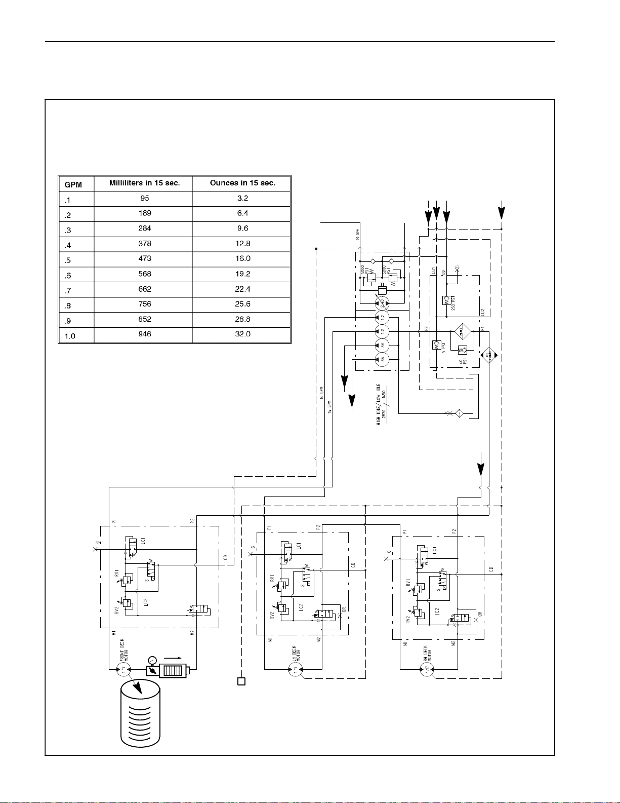
Cutting Deck Motor Case Drain Leakage (Using Tester with Pressure Gauge and Flow
Meter)
FRONT CUTTING DECK MOTOR
CASE DRAIN LEAKAGE TEST SHOWN
FROM 4WD MANIFOLD
CHARGE CIRCUIT
FROM FRONT WHEEL MOTORS
FROM REAR AXLE MOTOR
TRACTION CIRCUIT FLOW
TO STEERING & LIFT CIRCUITS
TO COOLING FAN CIRCUIT
TRACTION CIRCUIT FLOW
FILTER
MANIFOLD
FAN CIRCUIT
FROM COOLING
TESTER
MEASURING
CONTAINER
MANIFOLD
FRONT PTO
CAP
LH PTO
MANIFOLD
RH PTO
MANIFOLD
Groundsmaster 4000--D/4010--DHydraulic System Page 4 -- 54
Page 93

Procedure for Cutting Deck Motor Case Drain
Leakage Test
5. Sitonseatandstarttheengine.Movethrottletohigh
idle speed (2870 RPM). Move PTO switch to ON.
NOTE: Overa periodoftime,a deck motor can wearinternally. A worn motor may by--passoil to its case drain
causing the motor to be less efficient. Eventually,
enough oil loss will cause the deck motor to stall under
heavy cutting conditions. Continued operation with a
worn, inefficient motor can generate excessive heat,
causedamage to sealsandothercomponentsinthehydraulic system and affect quality of cut.
NOTE: Onemethodtofindafailingormalfunctioning
deck motor is to have another person observe the machine while mowing in dense turf. A bad motor will run
slower, produce fewer clippingsandmay cause a different appearance on the turf.
1. Make sure hydraulic oil is at normal operating temperature by operating the machine under load for
approximately ten (10) minutes. Make sure the hydraulic tank is full.
2. Park machine on a level surface with the cutting
decks lowered and off. Make sure engine is off and the
parking brake is applied.
6. While watching pressure gauge, slowly close flow
control valve on tester until a pressure of 1200 PSI (83
bar) is obtained.
NOTE: Use a graduated container, special tool
TOR4077, to measure case drain leakage (Fig. 44).
7. Have a second personcollect the flow from the case
drain line for 15 seconds, then move the PTO switch to
OFF and stopthe engine (Fig. 44). Record test results.
TEST RESULTS: Flow less than 22.4 ounces (662
ml) (0.7 GPM/2.6 LPM) of hydraulic fluid in 15 seconds.
8. If flow is more than 22.4 ounces (662 ml) (0.7
GPM/2.6LPM) in 15 seconds, the motor is worn or damaged and should be repaired or replaced.
9. After testing is completed, disconnect tester from
motorand hose. Reconnecthosetothedeckmotor.Remove cap from tee--fitting and reconnect case drain
hose.
CAUTION
Prevent personal injury and/or damage to equipment. Read all WARNINGS, CAUTIONS and Precautions for Hydraulic Testing at the beginning
of this section.
NOTE: The side deck motors are connected in series.
To isolate a faulty motor, both motors in the circuit may
havetobetestedbystarting with the left side motor first.
3. Disconnect hose from return of the motor to be
tested (Fig. 43). Install tester (flow and pressure) in serieswith the motor and disconnectedreturn hose. Make
sure the flow control valve on tester is fully open.
4. Disconnect themotor case drain hose (small diameterhose)where itconnects to hydraulic manifold tee--fitting(not at the motor). Put a steel cap on thefittingatthe
tee--fitting; leave the case drain hose open.
CAUTION
2
Figure 43
1. Deck motor (RH shown)
2. Return hose
3
1
3. Case drain hose
System
Hydraulic
Cutting deck blades will rotate when lowered
with PTO switch in ON position. Keep away from
cutting decks during test to prevent personal injuryfrom rotating blades. Do notstandinfrontof
the machine.
Groundsmaster 4000--D/4010--D Hydraulic SystemPage 4 -- 55
Figure 44
Page 94

Cutting Deck Gear Pump Flow (Using Tester with Pressure Gauge and Flow Meter)
FRONT DECK GEAR PUMP FLOW TEST SHOWN
FROM 4WD MANIFOLD
TRACTION CIRCUIT FLOW
TRACTION CIRCUIT FLOW
FROM FRONT WHEEL MOTORS
CHARGE CIRCUIT
FROM REAR AXLE MOTOR
FILTER
MANIFOLD
TESTER
FAN CIRCUIT
FROM COOLING
TO STEERING & LIFT CIRCUITS
TO COOLING FAN CIRCUIT
MANIFOLD
FRONT PTO
LH PTO
MANIFOLD
RH PTO
MANIFOLD
Groundsmaster 4000--D/4010--DHydraulic System Page 4 -- 56
Page 95

Procedure for Cutting Deck Gear Pump Flow Test
NOTE: Overaperiodof time,thegears andwearplates
in the pump can wear. A worn pump will by pass oil and
makethepumpless efficient.Eventually,enoughoilloss
willoccur to cause the cuttingdeckmotors to stall under
heavy cutting conditions. Continued operation with a
worn,inefficient pump can generateexcessive heatand
causedamage to the sealsandother components in the
hydraulic system.
7. Watchpressure gauge carefully while slowly closing
the flow control valve until 2000 PSI (138 bar) is obtained. Verifywith a phototac that the engine speed is
still 2870 RPM.
NOTE: If engine speed drops below 2870 RPM, pump
flow will decrease.
8. Flowindicationshouldbe approximately14GPM (53
LPM).
1. Make sure hydraulic oil is at normal operating temperature by operating the machine under load for
approximately ten (10) minutes. Make sure the hydraulic tank is full.
2. Park machine on a level surface with the cutting
decks lowered and off. Make sure engine is off and the
parking brake is applied.
CAUTION
Prevent personal injury and/or damage to equipment. Read all WARNINGS, CAUTIONS and Precautions for Hydraulic Testing at the beginning
of this section.
3. Locate deck manifold for gear pump section to be
tested. Disconnect hydraulic hose from fitting in deck
manifold port (P1) (Fig. 45).
4. Install tester (flow and pressure) in series with the
disconnected hose and hydraulic fitting in manifold port
(P1).
5. Make sure the flow control valve on tester is fully
open.
6. Start engine and move throttle to high idle speed
(2870 RPM). Do not engage the cutting decks.
9. Shut off engine and record test results.
10.If a pressure of 2000 PSI (138 bar) cannot be obtained or flow was less than 12 GPM (45 LPM),check
for restriction in the pump intake line. If line is not restricted, consider that gear pump section for cutting
deck circuit is worn or damaged.
11.After testing is completed, disconnect flow tester
fromhydraulic hose and manifold port.Reconnect hose
to the manifold.
RIGHT
FRONT
1
4
2
3
Figure 45
1. Front PTO manifold
2. Hyd. hose to front P1
3. LH PTO manifold
4. Hyd. hose to LH P1
System
Hydraulic
IMPORTANT: Do not fully restrict oil flow through
tester. In this test, the flow tester is positioned before the relief valve. Pump damage can occur if the
oil flow is fully restricted.
Groundsmaster 4000--D/4010--D Hydraulic SystemPage 4 -- 57
Page 96

Lift/Lower Circuit Relief Pressure (Using Pressure Gauge)
4WD
MANIFOLD
MANIFOLD
TRACTION
FILTER
MANIFOLD
S8
S9
S6
.035
.070
S5 S7
S4
S2 S3
RV2
S1
RV1
LIFT
MANIFOLD
GAUGE
PRESSURE
MANIFOLD
FAN DRIVE
FROM PTOMANIFOLDS
TO PTO (MOW) CIRCUIT
TO PTO (MOW) CIRCUIT
FROM DECK MOTORS
FROM FRONT PTO MANIFOLD
MANIFOLD
FROM RH PTO
CIRCUIT
FROM RH PTO
Rev. A Groundsmaster 4000-- D/4010--DHydraulic System Page 4 -- 58
Page 97

Procedure for Lift/Lower Circuit Relief Pressure
Test
NOTE: Before attempting to check or adjust lift/lower
circuit relief pressure, make sure that counterbalance
pressure is correctly adjusted (see Counterbalance
Pressure Test in this section).
1. Make sure hydraulic oil is at normal operating temperature by operating the machine under load for
approximately ten (10) minutes. Make sure the hydraulic tank is full.
B. Todecreasepressuresetting,removecap on reliefvalve andturntheadjustmentsocket on the valve
in a counterclockwise direction. A 1/8 turn on the
socket will make a measurable change in pressure
setting.
C. After relief valve adjustment, recheck pressure
setting and readjust as needed.
9. Ifrelief valveadjustmentdoes notchangerelief pressure, check for restriction in pump intake line, lift cylinder(s) internal leakage or gear pump damage.
2. Park machine on a level surface with the cutting
decks lowered and off. Make sure engine is off and the
parking brake is applied.
3. Remove controller cover to gain access to lift/lower
manifold (Fig. 46).
CAUTION
Prevent personal injury and/or damage to equipment. Read all WARNINGS, CAUTIONS and Precautions for Hydraulic Testing at the beginning
of this section.
4. Connect a 5,000 PSI (345 bar) pressure gauge to
test port G1 on lift/lower manifold (Fig. 47).
5. Sit on the seat and s tart the engine. Move throttle to
high idle speed (2870 RPM).
6. While sitting on the seat, depress the rear of one of
the lift switches to fully raise the cutting deck. Momentarilyholdtheswitch withthedeck fullyraisedwhile looking at the gauge.
GAUGE READING TO BE approximately 1600 PSI
(110 bar).
10.When testing is completed, disconnect pressure
gauge from test port. Install controller cover.
1
2
3
4
RIGHT
FRONT
Figure 46
1. Controller cover
2. Screw (2 used)
3. Flat washer (2 used)
4. U--nut (2 used)
System
Hydraulic
7. Release the lift switch,stoptheengineandrecord
test results.
8. Reliefvalve (RV1)islocated on thetopsideof the lift/
lowermanifold (Fig. 47). Adjustment of thisvalvecanbe
performed as follows:
NOTE: Donot remove the relief valve from the hydraulic manifold for adjustment.
A. To increase pressure setting, remove cap on reliefvalve andturntheadjustment socketonthevalve
in a clockwise direction. A 1/8 turn on the socket will
make a measurable change in pressure setting.
Groundsmaster 4000--D/4010--D Hydraulic SystemPage 4 -- 59
3
1. Lift/lower manifold
2. Test port G1
1
2
Figure 47
3. Relief valve RV1
Page 98

Steering Circuit Relief Pressure (Using Pressure Gauge)
4WD
MANIFOLD
MANIFOLD
TRACTION
FILTER
MANIFOLD
S8
S9
S6
.035
.070
S5 S7
S4
S2 S3
RV2
S1
RV1
LIFT
MANIFOLD
MANIFOLD
PRESSURE
GAUGE
FAN DRIVE
FROM PTOMANIFOLDS
TO PTO (MOW) CIRCUIT
TO PTO (MOW) CIRCUIT
FROM DECK MOTORS
FROM FRONT PTO MANIFOLD
FROM RH PTO
MANIFOLD
CIRCUIT
FROM RH PTO
Rev. A Groundsmaster 4000-- D/4010--DHydraulic System Page 4 -- 60
Page 99

Procedure for Steering Circuit Relief Pressure Test
1. Make sure hydraulic oil is at normal operating temperature by operating the machine under load for
approximately ten (10) minutes. Make sure the hydraulic tank is full.
2. Park machine on a level surface with the cutting
decks lowered and off. Make sure engine is off and the
parking brake is applied.
CAUTION
Prevent personal injury and/or damage to equipment. Read all WARNINGS, CAUTIONS and Precautions for Hydraulic Testing at the beginning
of this section.
3. Locate steering circuit pressure test port and connecta 5000PSI(350bar) pressuregaugeonto testport.
A. On Groundsmaster 4000--D machines, the test
port is located on the steering supply hydraulic tube
under the front of the machine (Fig. 48).
7. If pressure is incorrect, inspect steering relief valve
in steering control valve (see Steering Control Valve in
the Service and Repairs sectionof this chapter). If relief
valveis operatingproperlyand if lift/lower problemsalso
exist, flow divider in fan manifold and/or gear pump
(third section) should be suspected of wear and inefficiency.Ifsteeringwheel continuestoturnatend of cylinder travel (with lower than normal effort), steering
cylinder or steering control valve should be suspected
of wear or damage.
8. When testing is completed, disconnect pressure
gauge from test port.
1
B. On Groundsmaster 4010--D machines, the test
port is located on the steering supply hydraulic tube
under the operator seat (Fig. 49).
4. Starttheengine and move throttle tohighidleengine
speed (2870 RPM).
IMPORTANT: Hold steering wheel at full lock only
longenough to geta systemreliefpressurereading.
Holding the steering wheel against the stop for an
extended period can damage the steering control
valve.
5. Turn steering all the way in one direction and momentarily hold the steering wheel against resistance.
GAUGE READING TO BE 1300 to 1400 PSI (90 to
96 bar).
6. Stop the engine and record test results.
Figure 48
1. Steering circuit pressure test port (GM4000--D)
1
Figure 49
1. Steering circuit pressure test port (GM4010--D)
System
Hydraulic
Groundsmaster 4000--D/4010--D Hydraulic SystemPage 4 -- 61
Page 100

Steering Cylinder Internal Leakage
STEERING CYLINDER
R
L
CYLINDER FULLY
EXTENDED
LOOK FOR
LEAKAGE
STEEL CAP
STEERING WHEEL
TURNED FOR
RIGHT TURN
PB
1350
PSI
P
STEERING CONTROLT
Groundsmaster 4000--D/4010--DHydraulic System Page 4 -- 62
 Loading...