

Page 1
FormNo.3391-863RevA
G017540
CommercialWalk-BehindMower
FixedDeck,PistolGrip,HydroDrivewith
36inand48inTURBOFORCE
ModelNo.30934—SerialNo.315000001andUp
ModelNo.30938—SerialNo.315000001andUp
ModelNo.39934—SerialNo.315000001andUp
®
CuttingUnit
ModelNo.39938—SerialNo.315000001andUp
Registeratwww.T oro.com.
OriginalInstructions(EN)
*3391-863*A
Page 2
WARNING
Introduction
CALIFORNIA
Proposition65Warning
Thisproductcontainsachemicalorchemicals
knowntotheStateofCaliforniatocausecancer,
birthdefects,orreproductiveharm.
Theengineexhaustfromthisproduct
containschemicalsknowntotheStateof
Californiatocausecancer,birthdefects,
orotherreproductiveharm.
ThissparkignitionsystemcomplieswithCanadianICES-002.
Important:Thisengineisnotequippedwithaspark
arrestermufer.ItisaviolationofCaliforniaPublic
ResourceCodeSection4442touseoroperatetheengine
onanyforest-covered,brush-covered,orgrass-covered
land.Otherstatesorfederalareasmayhavesimilarlaws.
WARNING
Removingstandardoriginalequipmentpartsand
accessoriesmayalterthewarranty,traction,and
safetyofthemachine.FailuretouseoriginalToro
partscouldcauseseriousinjuryordeath.Making
unauthorizedchangestotheengine,fuelorventing
system,mayviolateEPAandCARBregulations.
Thisrotary-blade,lawnmowerisintendedtobeused
byresidentialhomeownersorprofessional,hired
operators.Itisdesignedprimarilyforcuttinggrasson
well-maintainedlawnsonresidentialorcommercial
properties.Itisnotdesignedforcuttingbrushorfor
agriculturaluses.
Readthisinformationcarefullytolearnhowtooperateand
maintainyourproductproperlyandtoavoidinjuryand
productdamage.Youareresponsibleforoperatingthe
productproperlyandsafely.
YoumaycontactTorodirectlyatwww .T oro.comforproduct
andaccessoryinformation,helpndingadealer,ortoregister
yourproduct.
Wheneveryouneedservice,genuineT oroparts,oradditional
information,contactanAuthorizedServiceDealerorToro
CustomerServiceandhavethemodelandserialnumbersof
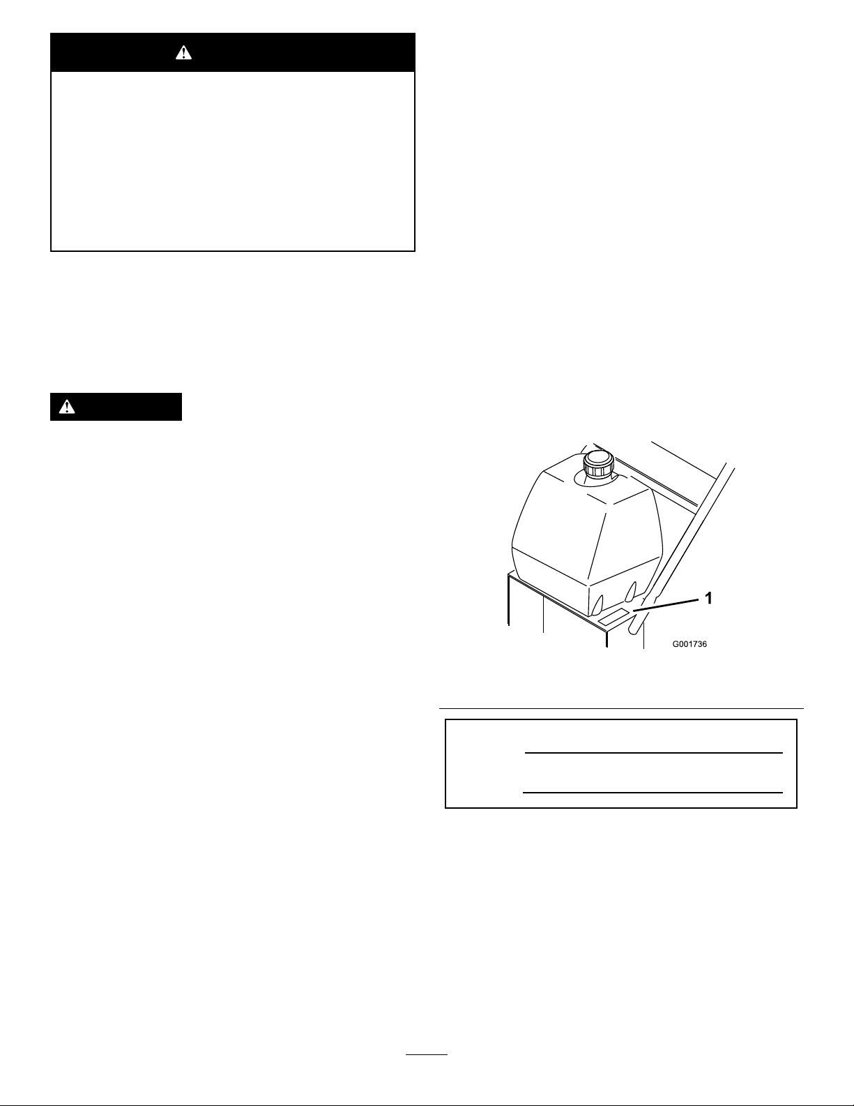
yourproductready.Figure1identiesthelocationofthe
modelandserialnumbersontheproduct.Writethenumbers
inthespaceprovided.
Replaceallpartsincluding,butnotlimitedto,tires,
belts,blades,andfuelsystemcomponentswith
originalToroparts.
Theenclosed
informationregardingtheUSEnvironmentalProtection
Agency(EPA)andtheCaliforniaEmissionControl
Regulationofemissionsystems,maintenance,and
warranty.Replacementsmaybeorderedthroughthe
enginemanufacturer.
Engine Owner's Man ual
issuppliedfor
Figure1
1.Modelandserialnumberlocation
ModelNo.
SerialNo.
©2014—TheToro®Company
8111LyndaleAvenueSouth
Bloomington,MN55420
Contactusatwww.Toro.com.
2
PrintedintheUSA
AllRightsReserved
Page 3

Thismanualidentiespotentialhazardsandhassafety
messagesidentiedbythesafetyalertsymbol(Figure2),
whichsignalsahazardthatmaycauseseriousinjuryordeath
ifyoudonotfollowtherecommendedprecautions.
Figure2
1.Safetyalertsymbol
Thismanualuses2wordstohighlightinformation.
Importantcallsattentiontospecialmechanicalinformation
andNoteemphasizesgeneralinformationworthyofspecial
attention.
Contents
Safety...........................................................................4
SafeOperatingPractices...........................................4
ToroMowerSafety..................................................6
SlopeIndicator.......................................................7
SafetyandInstructionalDecals.................................8
ProductOverview.........................................................13
Controls...............................................................13
Specications........................................................14
Attachments/Accessories........................................14
Operation....................................................................14
AddingFuel...........................................................14
CheckingtheEngine-OilLevel.................................15
PuttingSafetyFirst.................................................15
OperatingtheParkingBrake....................................16
StartingandStoppingtheEngine..............................16
OperatingtheNeutralLocks....................................17
OperatingtheMower-Blade-ControlKnob
(PTO)...............................................................18
TheSafety-InterlockSystem....................................18
DrivingtheMachineForwardandBackward..............19
BringingtheMachinetoNeutralPosition...................19
StoppingtheMachine.............................................19
PushingtheMachinebyHand..................................19
AdjustingtheFlowBafe........................................20
PositioningtheFlowBafe......................................20
TransportingtheMachine........................................21
SideDischargingorMulchingtheGrass.....................21
AdjustingtheHeight-of-Cut....................................21
AdjustingtheCasterPosition...................................22
AdjustingtheHandleHeight....................................23
Height-of-CutChart...............................................24
Maintenance.................................................................25
RecommendedMaintenanceSchedule(s)......................25
Lubrication...............................................................26
LubricatingtheMachine..........................................26
LubricatingtheCasterandWheelBearings.................26
GreasingtheMower-BeltIdler.................................26
GreasingthePumpControlandtheBell
Crank................................................................26
EngineMaintenance..................................................27
ServicingtheAirCleaner.........................................27
ServicingtheEngineOil..........................................27
ServicingtheSparkPlugs.........................................29
FuelSystemMaintenance...........................................30
ServicingtheFuelTank...........................................30
ServicingtheFuelFilter...........................................31
ServicingtheFuel-VentSystem................................31
DriveSystemMaintenance.........................................32
AdjustingtheSpeed-ControlLinkage........................32
AdjustingtheNeutralControlLinkages.....................32
AdjustingtheHydroControlLinkages.......................33
AdjustingtheControlRod.......................................35
AdjustingtheTracking...........................................36
AdjustingtheSpringAnchorLinks...........................36
CheckingtheTirePressure......................................37
CoolingSystemMaintenance......................................37
3
Page 4

CleaningtheAir-IntakeScreen.................................37
CleaningtheCoolingSystem....................................37
BrakeMaintenance....................................................38
ServicingtheBrake.................................................38
BeltMaintenance......................................................39
CheckingtheBelts..................................................39
ReplacingtheMowerBelt........................................39
AdjustingtheMowerBeltTension............................40
HydraulicSystemMaintenance....................................43
ServicingtheHydraulicSystem.................................43
MowerDeckMaintenance...........................................46
ServicingtheCuttingBlades.....................................46
AdjustingtheBladeBrake........................................48
ReplacingtheGrassDeector..................................48
Storage........................................................................49
CleaningandStorage..............................................49
Troubleshooting...........................................................51
Schematics...................................................................53
Safety
Note:Theadditionofattachmentsmadebyother
manufacturersthatdonotmeetAmericanNationalStandards
Institutecerticationwillcausenoncomplianceofthis
machine.
Improperlyusingormaintainingthemachinecanresult
ininjury.Toreducethepotentialforinjury,complywith
thesesafetyinstructionsandalwayspayattentiontothe
safetyalertsymbol,whichmeans
Danger
withtheinstructionmayresultinpersonalinjuryor
death.
Thisproductiscapableofamputatinghandsandfeetand
throwingobjects.Alwaysfollowallsafetyinstructionsto
avoidseriousinjuryordeath.
—personalsafetyinstruction.Failuretocomply
SafeOperatingPractices
ThefollowinginstructionsareadaptedfromANSI
B71.4-2012.
Caution, W ar ning ,
or
Training
•ReadtheOperator'sManualandothertrainingmaterial.If
theoperator(s)ormechanic(s)cannotreadorunderstand
theinformationitistheowner'sresponsibilitytoexplain
thismaterialtothem.
•Becomefamiliarwiththesafeoperationoftheequipment,
operatorcontrols,andsafetysigns.
•Alloperatorsandmechanicsshouldbetrained.The
ownerisresponsiblefortrainingtheusers.
•Neverletchildrenoruntrainedpeopleoperateorservice
theequipment.Localregulationsmayrestricttheageof
theoperator.
•Theowner/usercanpreventandisresponsiblefor
accidentsorinjuriesoccurringtopeopleordamageto
property.
Preparation
•Evaluatetheterraintodeterminewhataccessoriesand
attachmentsareneededtoproperlyandsafelyperform
thejob.Onlyuseaccessoriesandattachmentsapproved
bythemanufacturer.
•Wearappropriateclothingincludinghardhat,safety
glasses,andhearingprotection.Longhair,looseclothing,
orjewelrymaygettangledinmovingparts.
•Inspecttheareawheretheequipmentistobeusedand
removeallobjectssuchasrocks,toys,andwirewhichcan
bethrownbythemachine.
•Checkthatoperator'spresencecontrols,safetyswitches,
andshieldsareattachedandfunctioningproperly.Donot
operateunlesstheyarefunctioningproperly.
4
Page 5

Operation
•Lightningcancausesevereinjuryordeath.Iflightning
isseenorthunderisheardinthearea,donotoperate
themachine;seekshelter.
•Neverrunanengineinanenclosedarea.
•Onlyoperateingoodlight,keepingawayfromholesand
hiddenhazards.
•Besurealldrivesareinneutralandparkingbrakeis
engagedbeforestartingtheengine.Onlystarttheengine
fromtheoperator'sposition.
•Besureofyourfootingwhileusingthismachine,
especiallywhenbackingup.Walk;donotrun.Never
operateonwetgrass.Reducedfootingcouldcause
slipping.
•Slowdownanduseextracareonhillsides.Besureto
travelsidetosideonhillsides.Turfconditionscanaffect
thestabilityofthemachine.Usecautionwhileoperating
neardrop-offs.
•Slowdownandusecautionwhenmakingturnsandwhen
changingdirectionsonslopes.
•Neverraisedeckwiththebladesrunning.
•NeveroperatewiththePTOshieldorotherguardsnot
securelyinplace.Besureallinterlocksareattached,
adjustedproperly ,andfunctioningproperly.
•Neveroperatewiththedischargedeectorraised,
removedoraltered,unlessusingagrasscatcher.
•Donotchangetheenginegovernorsettingoroverspeed
theengine.
•Stoponlevelground,disengagedrives,engagethe
parkingbrake(ifprovided),andshutofftheenginebefore
leavingtheoperator'spositionforanyreason,including
emptyingthecatchersoruncloggingthechute.
•Stopequipmentandinspectbladesafterstrikingobjects
orifanabnormalvibrationoccurs.Makenecessary
repairsbeforeresumingoperations.
•Keephandsandfeetawayfromthecuttingunit.
•Lookbehindanddownbeforebackinguptobesureof
aclearpath.
•Nevercarrypassengersonthemachine.
•Keeppetsandbystandersaway .
•Slowdownandusecautionwhenmakingturnsand
crossingroadsandsidewalks.Stopbladesifnotmowing.
•Beawareofthemowerdischargedirectionanddonot
pointitatanyone.
•Donotoperatethemowerundertheinuenceofalcohol
ordrugs.
•Usecarewhenloadingorunloadingthemachineinto
orfromatrailerortruck.
•Usecarewhenapproachingblindcorners,shrubs,trees,
orotherobjectsthatmayobscurevision.
SafeHandlingofFuels
•Toavoidpersonalinjuryorpropertydamage,use
extremecareinhandlinggasoline.Gasolineisextremely
ammableandthevaporsareexplosive.
•Extinguishallcigarettes,cigars,pipes,andothersources
ofignition.
•Useonlyanapprovedfuelcontainer.
•Neverremovefuelcaporaddfuelwiththeengine
running.
•Allowenginetocoolbeforerefueling.
•Neverrefuelthemachineindoors.
•Neverstorethemachineorfuelcontainerwherethereis
anopename,spark,orpilotlightsuchasonawater
heateroronotherappliances.
•Neverllcontainersinsideavehicleoronatruckor
trailerbedwithaplasticliner.Alwaysplacecontainerson
thegroundawayfromyourvehiclebeforelling.
•Removeequipmentfromthetruckortrailerandrefuelit
ontheground.Ifthisisnotpossible,thenrefuelsuch
equipmentwithaportablecontainer,ratherthanfroma
fueldispensernozzle.
•Keepthenozzleincontactwiththerimofthefueltank
orcontaineropeningatalltimesuntilfuelingiscomplete.
•Donotuseanozzlelockopendevice.
•Iffuelisspilledonclothing,changeclothingimmediately.
•Neveroverllfueltank.Replacefuelcapandtighten
securely.
MaintenanceandStorage
•Disengagedrives,settheparkingbrake,stoptheengine
andremovethekeyordisconnectthespark-plugwire.
Waitforallmovementtostopbeforeadjusting,cleaning
orrepairingthemachine.
•Cleangrassanddebrisfromthecuttingunit,thedrives,
themufers,andtheenginetohelppreventres.Clean
upoilorfuelspillage.
•Lettheenginecoolbeforestoringanddonotstorenear
ame.
•Shutoffthefuelwhilestoringortransporting.Donot
storefuelnearamesordrainindoors.
•Parkthemachineonlevelground.Settheparkingbrake.
Neverallowuntrainedpersonneltoservicethemachine.
•Usejackstandstosupportcomponentswhenrequired.
•Carefullyreleasepressurefromcomponentswithstored
energy.
•Disconnectthebatteryorthespark-plugwirebefore
makinganyrepairs.Disconnectthenegativeterminal
rstandthepositivelast.Connectthepositiverstand
negativelast.
5
Page 6

•Usecarewhencheckingtheblades.Wraptheblade(s)or
weargloves,andusecautionwhenservicingthem.Only
replaceblades.Neverstraightenorweldthem.
•Keephandsandfeetawayfrommovingparts.Ifpossible,
donotmakeadjustmentswiththeenginerunning.
•Keepallpartsingoodworkingconditionandallhardware
tightened.Replaceallwornordamageddecals.
•Removeobstaclessuchasrocks,treelimbs,etc.fromthe
mowingarea.
•Watchforholes,rutsorbumps.Tallgrasscanhide
obstacles.
•Usecautionneardrop-offs,ditches,orembankments.
Themachinecouldsuddenlyturnoverifawheelgoes
overtheedgeofaclifforditch,orifanedgecavesin.
•Tobestprotectyourinvestmentandmaintainoptimal
performanceofyourToroequipment,countonT oro
genuineparts.Whenitcomestoreliability,T orodelivers
replacementpartsdesignedtotheexactengineering
specicationsofourequipment.Forpeaceofmind,insist
onTorogenuineparts.
Hauling
•Usecarewhenloadingorunloadingthemachineintoa
trailerortruck.
•Usefullwidthrampsforloadingmachineintotraileror
truck.
•Tiethemachinedownsecurelyusingstraps,chains,cable,
orropes.Bothfrontandrearstrapsshouldbedirected
downandoutwardfromthemachine.
ToroMowerSafety
ThefollowinglistcontainssafetyinformationspecictoToro
productsandothersafetyinformationyoumustknow.
Thisproductiscapableofamputatinghandsandfeetand
throwingobjects.Alwaysfollowallsafetyinstructionsto
avoidseriousinjuryordeath.
•Useextracarewithgrasscatchersorotherattachments.
Thesecanchangethestabilityofthemachine.
•Keepallmovementonslopesslowandgradual.Donot
makesuddenchangesinspeedordirection.
•Mowslopessidetoside.
•Donotmowslopesgreaterthan20degrees.
Service
•Neverstorethemachineorfuelcontainerinsidewhere
thereisanopename,suchasnearawaterheateror
furnace.
•Keepnutsandboltstight,especiallythebladeattachment
bolts.Keepequipmentingoodcondition.
•Nevertamperwithsafetydevices.Checksafetysystems
forproperoperationbeforeeachuse.
•Useonlygenuinereplacementpartstoensurethatoriginal
standardsaremaintained.
•Checkbrakeoperationfrequently.Adjustandserviceas
required.
Thisproductisdesignedforcuttingandrecyclinggrassor,
whenequippedwithagrassbagger,forcatchingcutgrass.
Anyuseforpurposesotherthanthesecouldprovedangerous
touserandbystanders.
GeneralOperation
•Besuretheareaisclearofotherpeoplebeforemowing.
Stopthemachineifanyoneentersthearea.
•Donottouchequipmentorattachmentpartswhichmay
behotfromoperation.Allowtocoolbeforeattempting
tomaintain,adjustorservice.
•UseonlyToroapprovedattachments.Warrantymaybe
voidedifusedwithunapprovedattachments.
•Checkcarefullyforoverheadclearances(i.e.branches,
doorways,electricalwires)beforeoperatingunderany
objectsanddonotcontactthem.
SlopeOperation
Allslopesandrampsrequireextracaution.Ifyoufeeluneasy
onaslope,donotmowit.
6
Page 7
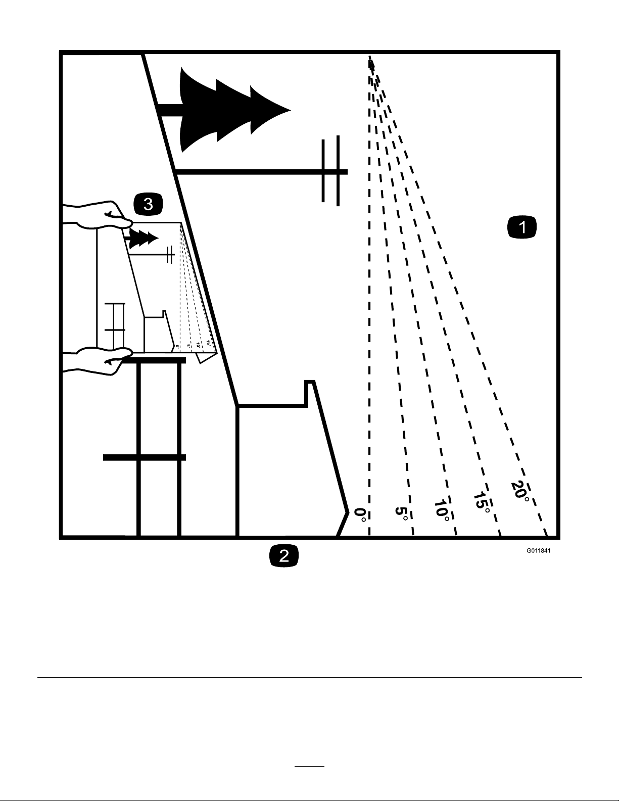
SlopeIndicator
G011841
Figure3
Thispagemaybecopiedforpersonaluse.
1.Themaximumslopeyoucansafelyoperatethemachineonis20degrees.Usetheslopecharttodeterminethedegreeofslope
ofhillsbeforeoperating.Donotoperatethismachineonaslopegreaterthan20degrees.Foldalongtheappropriateline
tomatchtherecommendedslope.
2.Alignthisedgewithaverticalsurface,atree,building,fencepole,etc.
3.Exampleofhowtocompareslopewithfoldededge.
7
Page 8
SafetyandInstructionalDecals
Safetydecalsandinstructionsareeasilyvisibletotheoperatorandarelocatednearanyareaofpotential
danger.Replaceanydecalthatisdamagedorlost.
Manufacturer'sMark
1.Indicatesthebladeisidentiedasapartfromtheoriginal
machinemanufacturer.
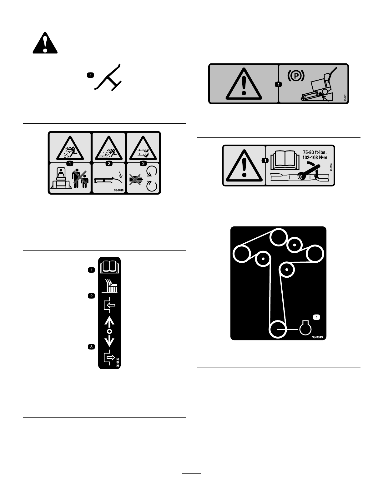
93-7010
1.Thrownobjecthazard—keepbystandersasafedistance
fromthemachine.
2.Thrownobjecthazard,mower—keepthedeectorinplace.
3.Cutting/dismembermentofhandorfoot—stayawayfrom
movingparts.
95-5852
1.Warning—engagetheparkingbrakeandchockorblockthe
wheelswhenparkingthemachineonaslope.
98-5130
1.Warning—readtheOperator'sManualforinstructionson
torquingthebladebolt/nutto102-106N⋅m(75-80ft-lb).
1.ReadtheOperator's
Manualforinstructionson
operatingthecuttingblade
2.Pushforwardtoengage
99-3943
1.Engine
95-5537
3.Pullbacktodisengage
8
Page 9
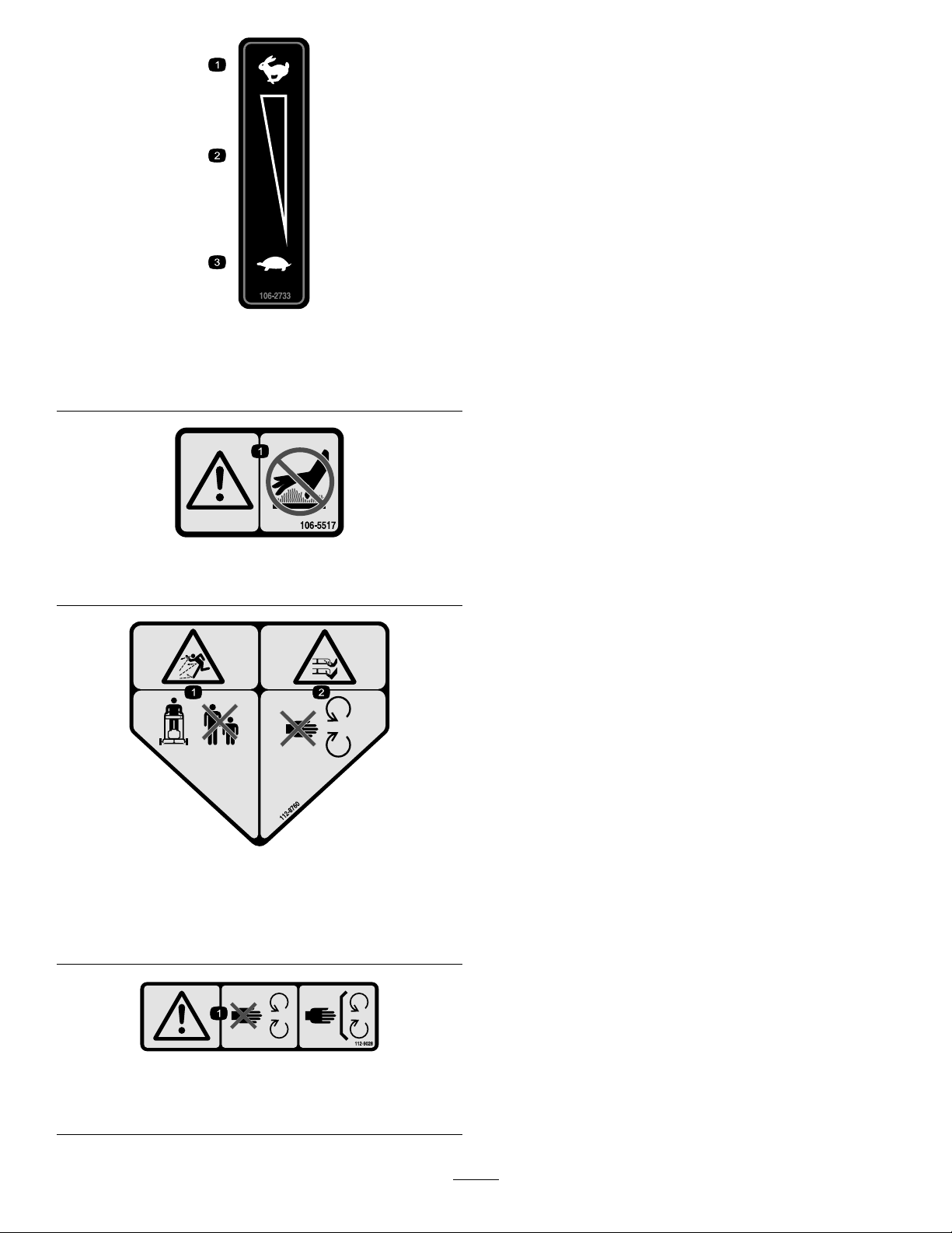
106-2733
1.Fast
2.Continuousvariable
setting
1.Warning—donottouchthehotsurface.
3.Slow
106-5517
112-8760
1.Thrownobjecthazard—keepbystandersasafedistance
fromthemachine.
2.Cutting/dismembermentofhandorfoot—stayawayfrom
movingparts.
112-9028
1.Warning—stayawayfrommovingparts;keepallguardsin
place.
9
Page 10
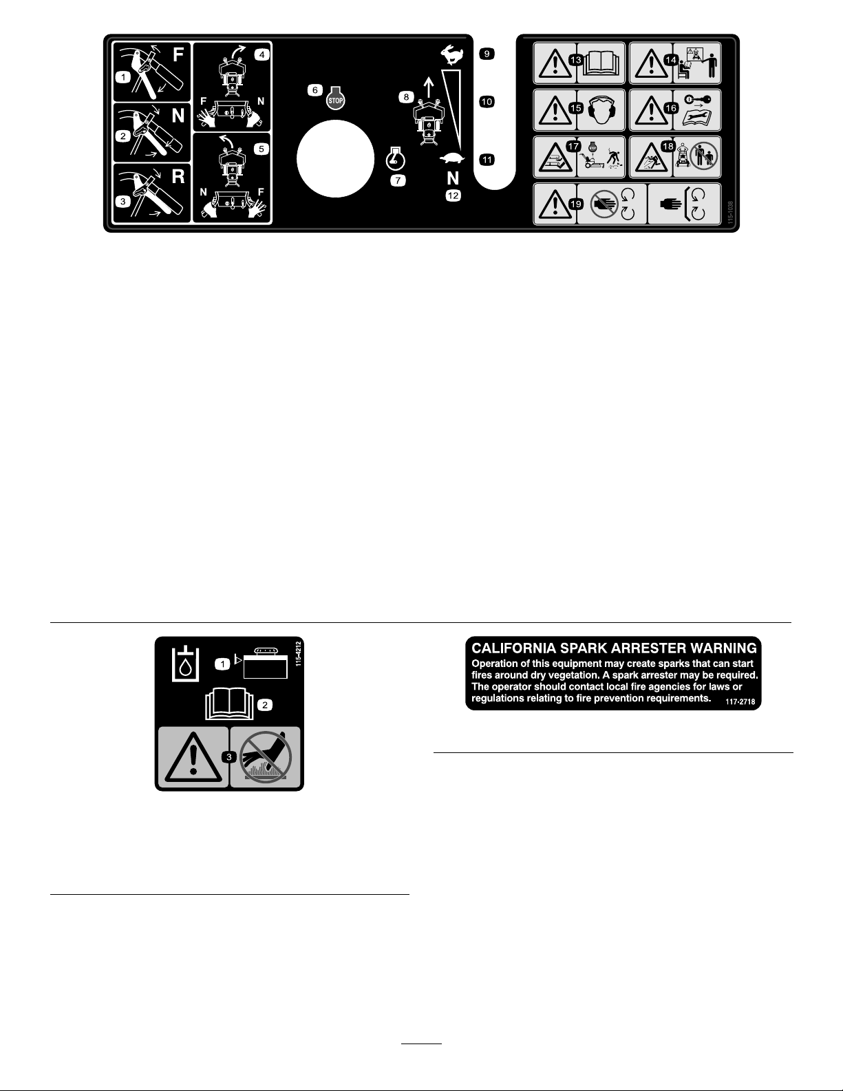
115-1038
1.Forward
2.Neutral
3.Reverse
4.Toturnrightmovethelefthandleverintotheforwardpositionwhiletherighthandleverisintheneutralposition.
5.Toturnleftmovetherighthandleverintotheforwardpositionwhilethelefthandleverisintheneutralposition.
6.Engine—stop
7.Engine—run
8.Groundspeed
9.Fast
10.Continuousvariablesetting
11.Slow
12.Neutral
13.Warning—readtheOperator'sManual.
14.Warning—donotoperatethismachineunlessyouaretrained.
15.Warning—wearhearingprotection.
16.Warning—removetheignitionkeybeforeperformingmaintenanceonthemachine.
17.Cutting/dismembermenthazardofhandorfoot,mowerblade—stoptheenginebeforeleavingtheoperatingposition.
18.Thrownobjecthazard—keepbystandersasafedistancefromthemachine.
19.Warning—stayawayfrommovingparts;keepallguardsinplace.
115-4212
1.Hydraulicoillevel3.Warning—donottouchthe
hotsurface.
2.ReadtheOperator's
Manual.
117-2718
10
Page 11
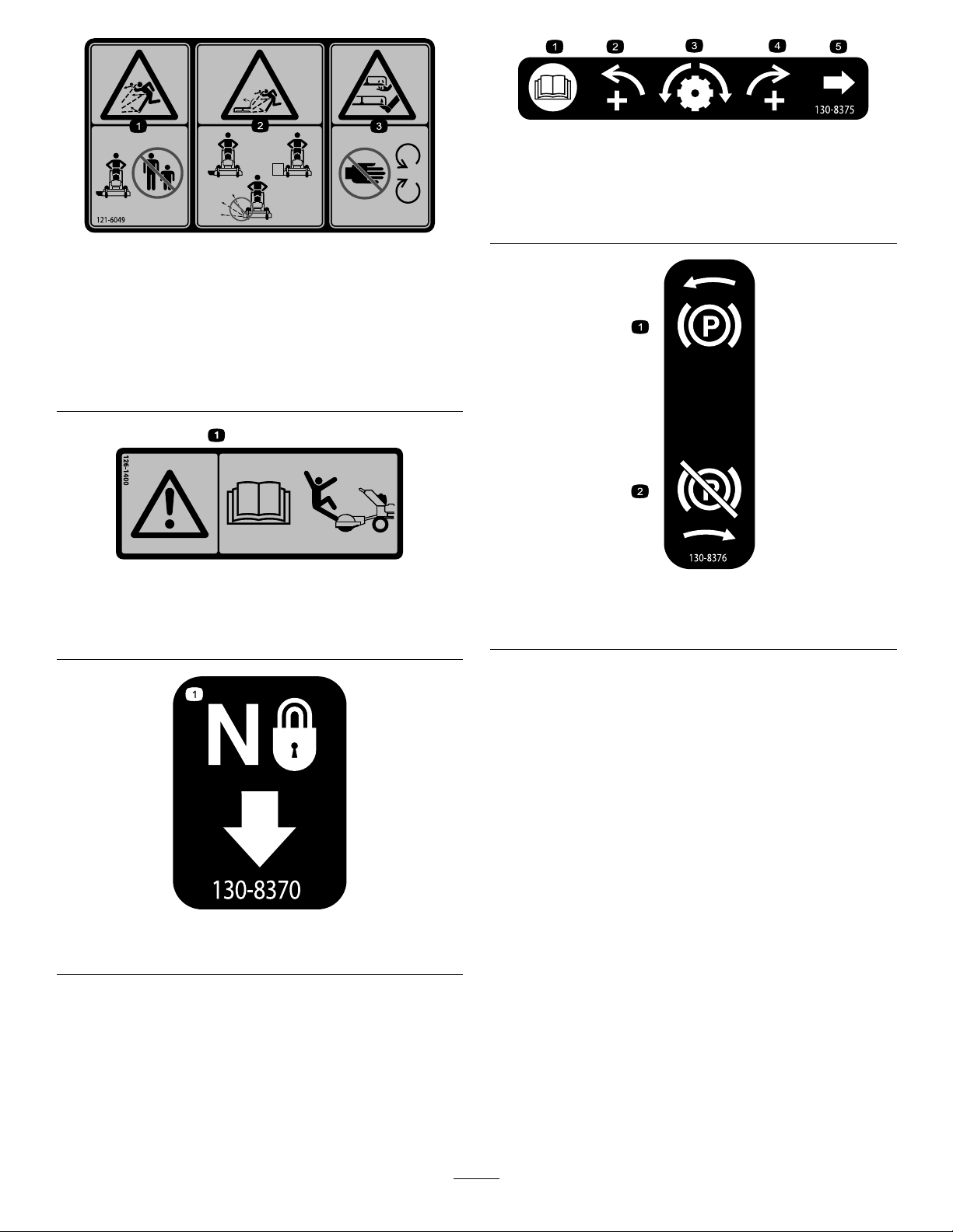
130-8375
121-6049
1.Thrownobject
hazard—keepbystanders
awayfromthemachine.
2.Thrownobjecthazard,
mower—donotoperate
themowerwithguardsor
shieldsremoved.
3.Cutting/dismemberment
hazardofhandorfoot,
mowerblade—keephands
awayfrommovingparts.
126-1400
1.Warning-ReadtheOperator’smanual.UseonlyTororiding
attachments.Useofotherridingattachmentsmaycreatea
hazardousconditionresultingininjury.
1.ReadtheOperator's
Manual.
2.Increaseleft
3.Trackingadjustment
4.Increaseright
5.Trackingadjustmentknob
130-8376
1.Engagetheparkingbrake.2.Disengagetheparking
brake.
1.Neutrallock
130-8370
11
Page 12

131-1180
1.ReadtheOperator's
Manual.
2.Short,lightgrass;dry
conditions;maximum
dispersion
3.Baggingsetting
4.Tall,densegrass;wet
conditions;maximum
groundspeed
12
Page 13
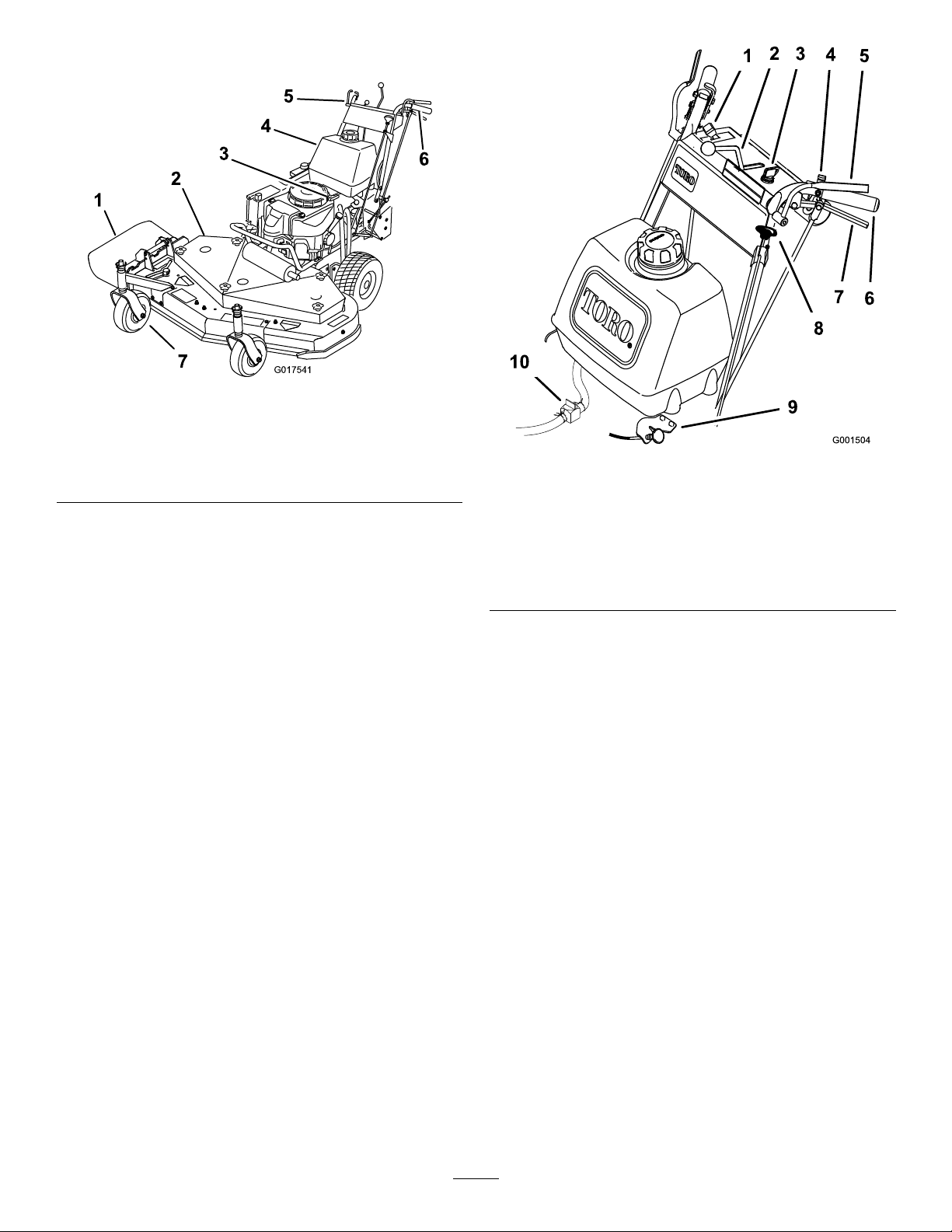
ProductOverview
G017541
Figure4
1.Sidedischarge5.Controls
2.Mowerdeck6.Handle
3.Recoil-starthandle
4.Gastank
Controls
Becomefamiliarwithallthecontrols(Figure5)beforeyou
starttheengineandoperatethemachine.
7.Casterwheel
Figure5
1.Throttlecontrol6.Handle
2.Speed-controllever
3.Ignitionswitch
4.Neutrallock
5.Operator-presence-control
levers(OPC)
7.Drivelever
8.Blade-controlknob(PTO)
9.Choke
10.Fuel-shutoffvalve
ThrottleControl
Thethrottlecontrolhas2positions:FastandSlow.
Operator-Presence-Control(OPC)
Levers
WhenyousqueezetheOPCleversagainstthehandles,
theOPCsystemsensesthattheoperatorisinthenormal
operatingposition.WhenyoureleasetheOPClevers,the
OPCsystemsensesthattheoperatorhasleftthenormal
operatingposition,andthesystemwillstoptheengineif
eitherthespeed-controlleverisnotintheNeutralpositionor
theblade-control(PTO)knobisengaged.
Blade-ControlKnob(PTO)
Theblade-controlknob(PTO)isusedtoengageand
disengagethedrivebelttodrivethemowerbladeswiththe
OPCleverspressedagainstthehandles.Pulltheknobupto
engagethebladesanddowntodisengagetheblades.
IgnitionSwitch
Thisswitchisusedinconjunctionwithrecoilstarterandhas
2positions:RunandOff.
Speed-ControlLever
Thismachinehasavariable-speedcontrolwithaNeutral
position.Thiscontrolshowfastthemachinetravelsforward.
DriveLevers
Releasethedriveleverstoengageforwardtractionoperation
andsqueezetheleversuntilanincreaseinforceisfeltto
gointoneutralpositionandcontinuetosqueezetogoin
reverse.Squeezetheright-sidedrivelevertoturnrightand
theleft-sidedrivelevertoturnleft.
NeutralLock
Squeezethedriveleversbackuntilanincreaseinforceisfelt,
andmovethelockstotherearforneutrallock.
Recoil-StartHandle
Pulltherecoil-starthandletostarttheengine(notshown
inFigure4).
13
Page 14

Fuel-ShutoffValve
Closethefuel-shutoffvalvewhentransportingorstoringthe
machine.
Operation
AddingFuel
Choke
Usethechoketostartacoldengine.
Specications
Note:Specicationsanddesignaresubjecttochange
withoutnotice.
36-inchmowers:
Widthwithdeectordown118.4cm(46.6inches)
Length
Height
Weight
48-inchmowers:
Widthwithdeectordown161.3cm(63-1/2inches)
Length
Height
Weight
203.2cm(80inches)
11 1.8cm(44inches)
241kg(532lb)
198.9cm(78-3/8inches)
11 1.8cm(44inches)
259kg(570lb)
•Forbestresults,useonlyclean,fresh(lessthan30days
old),unleadedgasolinewithanoctaneratingof87or
higher((R+M)/2ratingmethod).
•Ethanol:Gasolinewithupto10%ethanol(gasohol)
or15%MTBE(methyltertiarybutylether)byvolume
isacceptable.EthanolandMTBEarenotthesame.
Gasolinewith15%ethanol(E15)byvolumeisnot
approvedforuse.Neverusegasolinethatcontainsmore
than10%ethanolbyvolume,suchasE15(contains15%
ethanol),E20(contains20%ethanol),orE85(contains
85%ethanol).Usingunapprovedgasolinemaycause
performanceproblemsand/orenginedamagewhichmay
notbecoveredunderwarranty.
•Donotusegasolinecontainingmethanol.
•Donotstorefueleitherinthefueltankorfuelcontainers
overthewinterunlessafuelstabilizerisused.
•Donotaddoiltogasoline.
DANGER
Incertainconditions,gasolineisextremely
ammableandhighlyexplosive.Areorexplosion
fromgasolinecanburnyouandothersandcan
damageproperty.
Attachments/Accessories
AselectionofToroapprovedattachmentsandaccessoriesis
availableforusewiththemachinetoenhanceandexpand
itscapabilities.ContactyourAuthorizedServiceDealeror
Distributororgotowww .Toro.comforalistofallapproved
attachmentsandaccessories.
•Fillthefueltankoutdoors,inanopenarea,
whentheengineiscold.Wipeupanygasoline
thatspills.
•Neverllthefueltankinsideanenclosedtrailer.
•Donotllthefueltankcompletelyfull.Add
gasolinetothefueltankuntilthelevelis6to13
mm(1/4to1/2inch)belowthebottomofthe
llerneck.Thisemptyspaceinthetankallows
gasolinetoexpand.
•Neversmokewhenhandlinggasoline,andstay
awayfromanopenameorwheregasoline
fumesmaybeignitedbyaspark.
•Storegasolineinanapprovedcontainerand
keepitoutofthereachofchildren.Neverbuy
morethana30-daysupplyofgasoline.
•Donotoperatewithoutentireexhaustsystemin
placeandinproperworkingcondition.
14
Page 15

DANGER
Incertainconditionsduringfueling,static
electricitycanbereleasedcausingasparkwhich
canignitethegasolinevapors.Areorexplosion
fromgasolinecanburnyouandothersandcan
damageproperty.
•Alwaysplacegasolinecontainersontheground
awayfromyourvehiclebeforelling.
•Donotllgasolinecontainersinsideavehicleor
onatruckortrailerbedbecauseinteriorcarpets
orplastictruckbedlinersmayinsulatethe
containerandslowthelossofanystaticcharge.
UsingFuelStabilizer/Conditioner
Useafuelstabilizer/conditionerinthemachinetokeepthe
fuelfreshduringstorageof90daysorless.Ifyouarestoring
themachineforlonger,drainthefueltank;refertoDraining
theFuelTank(page30).
Important:Donotusefueladditivescontaining
methanolorethanol.
Addthecorrectamountoffuelstabilizer/conditionertothe
fuel,andfollowthedirectionsofthemanufacturer.
Note:Fuelstabilizer/conditionerismosteffectivewhen
mixedwithfreshgasoline.Tominimizethechanceofvarnish
depositsinthefuelsystem,usefuelstabilizeratalltimes.
•Whenpractical,removegas-poweredequipment
fromthetruckortrailerandrefueltheequipment
withitswheelsontheground.
•Ifthisisnotpossible,thenrefuelsuch
equipmentonatruckortrailerfromaportable
container,ratherthanfromagasolinedispenser
nozzle.
•Ifagasolinedispensernozzlemustbeused,
keepthenozzleincontactwiththerimofthe
fueltankorcontaineropeningatalltimesuntil
fuelingiscomplete.
WARNING
Gasolineisharmfulorfatalifswallowed.Long-term
exposuretovaporscancauseseriousinjuryand
illness.
•Avoidprolongedbreathingofvapors.
•Keepfaceawayfromnozzleandgastankor
conditionerbottleopening.
•Keepgasawayfromeyesandskin.
FillingtheFuelTank
1.Shuttheengineoffandsettheparkingbrake.
2.Cleanaroundthefuel-tankcapandremovethecap.
Addunleadedregulargasolinetothefueltank,untilthe
levelis6to13mm(1/4to1/2inch)belowthebottom
ofthellerneck.Thisspaceinthetankallowsgasoline
toexpand.Donotllthefueltankcompletelyfull.
3.Installthefuel-tankcapsecurely.Wipeupanygasoline
thatmayhavespilled.
CheckingtheEngine-OilLevel
Beforeyoustarttheengineandusethemachine,check
theoillevelintheenginecrankcase;refertoCheckingthe
Engine-OilLevel(page28).
PuttingSafetyFirst
Carefullyreadallthesafetyinstructionsanddecalsinthe
safetysection.Knowingthisinformationcouldhelpyouor
anybystandersavoidinjury.
Theuseofprotectiveequipmentforeyes,hearing,feetand
headisrecommended.
CAUTION
Thismachineproducessoundlevelsinexcessof
85dBAattheoperator'searandcancausehearing
lossthroughextendedperiodsofexposure.
Wearhearingprotectionwhenoperatingthis
machine.
Figure6
1.Warning—wearhearingprotection.
15
Page 16
OperatingtheParkingBrake
Alwayssettheparkingbrakewhenyoustopthemachineor
leaveitunattended.Beforeeachuse,checktheparkingbrake
forproperoperation.
Iftheparkingbrakedoesnotholdsecurely,adjustit.Referto
ServicingtheParkingBrake.
CAUTION
Childrenorbystandersmaybeinjuredifthey
moveorattempttooperatethemachinewhileitis
unattended.
Alwaysremovetheignitionkeyandsettheparking
brakewhenleavingthemachineunattended,even
ifjustforafewminutes.
SettingtheParkingBrake
Pulltheparking-brakeleverrearward(Figure7).
Figure7
1.Parking-brakelever(inthereleasedposition)
ReleasingtheParkingBrake
Pushtheparking-brakeleverforward.
StartingandStoppingthe Engine
StartingtheEngine
1.Connectthewirestothesparkplugs.
2.Openthefuelvalve.
Note:Acold-weatherstartingkithasbeen
incorporatedtoassistenginestartingincoldweather
orwhenthemachinehasnotbeenrunforaperiod
oftime.
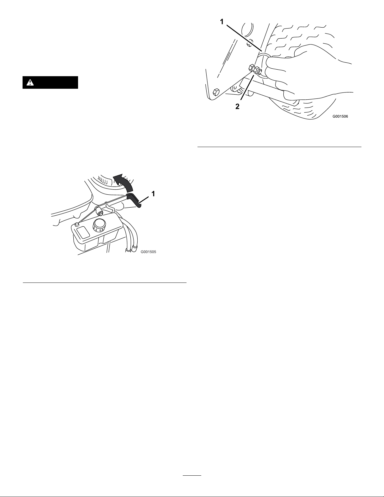
Tousethecold-weatherstartingkit:
•Graspthesplitring(Figure8)ontherightsideof
themachine,pulltheringandchainstraightout
fromthesideofthemachine,andhookthering
overthecontrol-shieldbolt.
Figure8
1.Splitring2.Control-shieldbolt
•Aftertheengineisstarted,pullthechainstraight
outfromthesideofthemachineuntiltheringcan
beremovedfromshieldbolt.Slowlyreleasethe
tensiononthechain.
3.Disengagetheblade-controlknob(PTO)andmove
thespeed-controllevertotheneutralposition.
4.Movethedriveleverstotheneutralpositionandset
theneutrallocks.
5.Settheparkingbrake.
6.Turntheignitionkeytotherunposition(Figure5).
7.Tostartacoldengine,movethethrottlecontrol
midwaybetweenthefastandslowpositions.
8.Tostartawarmengine,movethethrottlecontrolto
thefastposition.
9.Pullthechokeknobiftheengineiscold(Figure5).
Note:Awarmorhotengineusuallydoesnotrequire
anychoking.
10.Grasptherecoil-starthandlermlyandpullitout
untilpositiveengagementresults;thenpullthehandle
vigorouslytostarttheengine.Allowtheropetorecoil
slowly.
11.Pushthechoketotheoffpositionastheenginewarms
up(Figure9).
12.Iftheengineiscold,allowittowarmupandthen
movethethrottlecontroltothefastposition.
StoppingtheEngine
1.Movethethrottlelevertotheslowposition(Figure9).
2.Movethedriveleverstotheneutralpositionandset
theneutrallocks.
3.Disengagetheblade-controlknob(PTO)andmove
thespeed-controllevertotheneutralposition.
4.Lettheengineidlefor30to60secondsbeforeturning
theengineoff.
5.Tostoptheengine,turntheignitionkeytooff.
16
Page 17
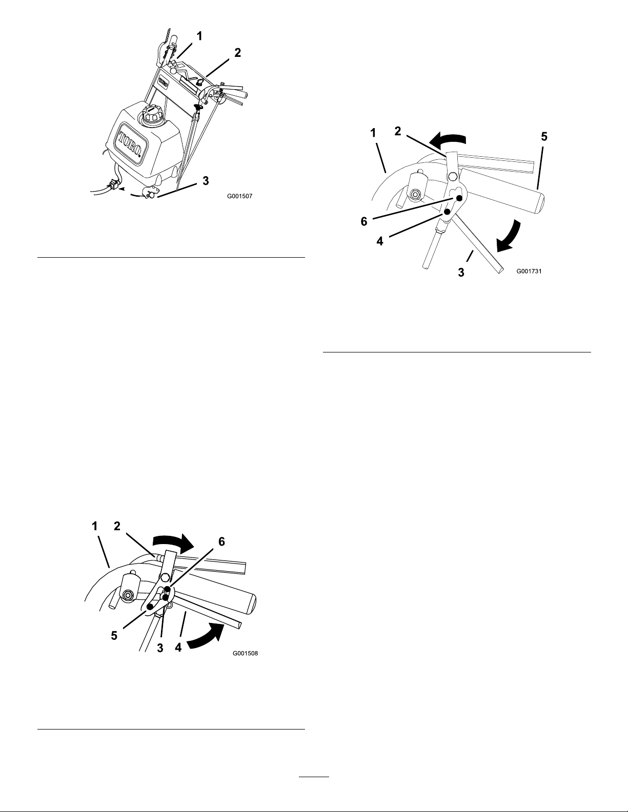
Figure9
ReleasingtheNeutralLock
1.Squeezethedriveleversbackuntilanincreaseinforce
isfelt.
2.Placeyourthumbsontheupperpartofthelocksand
movethemforwarduntilthepinsareintheforward
slot(Figure11).
1.Throttlelever
2.Ignitionswitch
3.Choke
Important:Makesurethatthefuel-shutoff
valveisclosedbeforetransportingorstoringthe
machine,asfuelleakagemayoccur.Beforestoring
themachine,disconnectthewiresfromthespark
plugstopreventthepossibilityofaccidentally
startingtheengine.
OperatingtheNeutralLocks
Alwayssettheneutrallockwhenyoustopthemachine.Set
theparkingbrakeifitisleftunattended.
SettingtheNeutralLock
1.Squeezethedriveleversbackuntilanincreaseinforce
isfelt.
2.Placethumbsontheupperpartofthelocksandmove
themback(Figure10).
Figure11
1.Handle
2.Neutrallock5.Handle
3.Drivelever6.Forwardslot
4.Pininfullspeedforward
Figure10
1.Handle4.Drivelever
2.Neutrallock
3.Neutralposition6.Reverseposition
5.Fullspeedforward
17
Page 18

Operatingthe
TheSafety-InterlockSystem
Mower-Blade-ControlKnob
(PTO)
Theblade-controlknob(PTO)isusedinconjunctionwith
theOperatorPresenceControl(OPC)leverstoengageand
disengagethemowerblades.
EngagingtheMowerBlades(PTO)
1.Toengagetheblades,squeezetheOperatorPresence
Control(OPC)leversagainstthehandlegrips(Figure
12).
2.Pulltheblade-controlknob(PTO)up.HoldtheOPC
leversagainstthehandlegrip.
Note:TheenginewillstopiftheOPCleversare
releasedifthemowerisrunningandthespeed-control
leverisnotinneutral.
3.Starttheengineandrepeattheproceduretoengagethe
mowerbladesiftheoperatorpresencecontrol(OPC)
leversarereleased.
CAUTION
Ifsafetyinterlockswitchesaredisconnectedor
damagedthemachinecouldoperateunexpectedly
causingpersonalinjury.
•Donottamperwiththeinterlockswitches.
•Checktheoperationoftheinterlockswitches
dailyandreplaceanydamagedswitchesbefore
operatingthemachine.
UnderstandingtheSafety-Interlock
System
Thesafetyinterlocksystemisdesignedtopreventthemower
fromstartingunless:
•Theblade-controlknob(PTO)ispushedoff.
•Thespeed-controlleverisintheNeutralposition.
Thesafetyinterlocksystemisdesignedtostoptheengine
when:
•Theoperator-presence-control(OPC)leversarereleased
withthemowerengagedand/orthespeedcontrolisout
ofneutral.
•Thespeed-controlleverisshiftedoutofneutralwithout
holdingOPCleversorwiththebrakeengaged.
•Theblade-controlknob(PTO)ispulledupwithout
holdingtheOPClevers.
Figure12
1.Throttlelever4.DriveLever
2.OperatorPresence
Controllevers(OPC)
3.Handle
5.Blade-controlknob(PTO)
DisengagingtheMowerBlades(PTO)
Themowerbladescanbedisengagedbyoneofthefollowing
steps.
1.Pushtheblade-controlknob(PTO)downtotheoff
position(Figure12).
2.ReleasingtheOperatorPresenceControl(OPC)levers
willstoptheengineandstoptheblades(Figure12)
withtheblade-controlleverengaged.
TestingtheSafety-InterlockSystem
ServiceInterval:Beforeeachuseordaily
Testthesafety-interlocksystembeforeyouusethemachine
eachtime.Ifthesafetysystemdoesnotoperateasdescribed,
haveanAuthorizedServiceDealerrepairthesafetysystem
immediately.
WARNING
Whiletestingthesafety-interlocksystem,the
machinemaymoveforwardandcausepersonal
injuryorpropertydamage.
•Performthesafety-interlocktestinanopenarea.
•Ensurethatnooneisstandinginfrontofthe
machinewhileperformingthesafety-interlock
test.
1.Settheneutrallocksandplacespeed-controlleverin
neutral.
2.Starttheengine;refertoStartingandStoppingthe
Engine.
3.WithoutholdingtheOperatorPresenceControl(OPC)
levers,pulltheblade-controlknob(PTO)up.The
engineshouldstop.
18
Page 19

4.Pushtheblade-controlknobdowntooff.
DrivingBackward
5.Withenginerunning,holddowntheOPClevers.
Pulltheblade-controlknob(PTO)up.Thedrivebelt
shouldengageandthemowerbladesshouldbegin
rotating.
6.Withenginerunning,releasetheOPClevers.The
engineshouldstop.
7.Withtheenginerunning,movethespeed-controllever
forwardslightly.ReleasetheOPClevers.Theengine
shouldstop.
8.Ifalltheaboveconditionsarenotmet,havean
AuthorizedServiceDealerrepairthesafetysystem
immediately.
DrivingtheMachineForward andBackward
Thethrottlecontrolregulatestheenginespeedasmeasured
inrpm(revolutionsperminute).Placethethrottlecontrolin
theFastpositionforbestmowingperformance.
DrivingForward
1.Releasetheparkingbrake.
2.Togoforward,movethespeed-controllevertothe
desiredspeed.
3.Releasetheneutrallock.RefertoReleasingtheNeutral
Lock(page17).
4.Slowlyreleasethedriveleverstomoveforward(Figure
13).
Togostraight,releasethedriveleversequally(Figure
13).
Toturn,squeezethedriveleveronthesideofthe
directionwhichyouwanttoturn(Figure13).
Fromneutral,slowlysqueezethedriveleverstomove
rearward(Figure13).
BringingtheMachineto NeutralPosition
Alwayssettheneutrallockandparkingbrakewhenyoustop
themachine.
1.Squeezethedriveleverstoneutralposition.
2.Settheneutrallocks.RefertoOperatingtheNeutral
Locks(page17).
3.Movespeed-controllevertoneutralposition.
Note:Thespeed-controllevercanalsobeusedto
bringthemowertoneutralpositionandthensetthe
neutrallocks.
StoppingtheMachine
1.Tostopthemachine,squeezethedriveleverstothe
neutralpositionandengageneutrallocks.
2.Movespeed-controlleverintoneutral.
3.Stoptheengine;refertoStoppingtheEngine.
4.Waitforallmovingpartstostopbeforeleavingthe
operatingposition.Settheparkingbrake.
CAUTION
Childrenorbystandersmaybeinjuredifthey
moveorattempttooperatethemachinewhileitis
unattended.
Alwaysremovetheignitionkeyandsettheparking
brakewhenleavingthemachineunattended,even
ifjustforafewminutes.
1.Drivelever
Figure13
2.Speed-controllever
PushingtheMachinebyHand
Thebypassvalvesallowthemachinetobepushedbyhand
withouttheenginerunning.
Important:Alwayspushthemachinebyhand.Never
towthemachinebecausehydraulicdamagemayoccur.
1.DisengagethePTO ,movethemotioncontrolleversto
theneutrallockedpositionandsettheparkingbrake.
2.Openthebypassvalvesbyturningthemcounter
clockwise1to2turns.Thisallowshydraulicuidto
bypassthepumpsandthewheelstoturn(Figure14).
3.Releasetheparkingbrake.
4.Pushthemachinetothedesiredlocation.
5.Settheparkingbrake.
6.Closethebypassvalves,butdonotovertightenthem.
19
Page 20

Note:Rotatethebypassvalvesamaximumof2turns
g012676
1 2
G012677
G012678
sothevalvedoesnotcomeoutofthebodycausing
uidtorunout.
Important:Donotstartoroperatethemachine
withthebypassvalvesopen.Damagetosystem
mayoccur.
Figure14
1.Bypassvalve
PositioningtheFlowBafe
Thefollowingguresareonlyrecommendationsforuse.
Adjustmentswillvarybygrasstype,moisturecontent,and
heightofgrass.
Note:Iftheenginepowerdrawsdownandthemower
groundspeedisthesame,openupthebafe.
PositionA
Thisisthefullrearposition(seeFigure16).Thesuggested
useforthispositionisafollows:
•Useforshort,lightgrassmowingconditions.
•Useindryconditions.
•Forsmallergrassclippings.
•Propelsgrassclippingsfartherawayfromthemower.
AdjustingtheFlowBafe
Themowerdischargeowcanbeadjustedfordifferenttypes
ofmowingconditions.Positionthecamlockandbafeto
givethebestqualityofcut.
1.DisengagethePTO ,movethemotioncontrolleversto
theneutrallockedpositionandsettheparkingbrake.
2.Stoptheengine,removethekey,andwaitforallmoving
partstostopbeforeleavingtheoperatingposition.
3.Toadjustthebafe,loosenthenut(Figure15).
4.Adjustthebafeandnutintheslottothedesired
dischargeowandtightenthenut.
Figure16
PositionB
Usethispositionwhenbagging(Figure17).
Figure15
2.Nut
Figure17
20
1.Slot
Page 21

PositionC
G012679
SideDischargingorMulching
Thisisthefullopenposition.Thesuggesteduseforthis
positionisasfollows(Figure18):
•Useintall,densegrassmowingconditions.
•Useinwetconditions.
•Lowerstheenginepowerconsumption.
•Allowsincreasedgroundspeedinheavyconditions.
Figure18
theGrass
Thismowerhasahingedgrassdeectorthatdisperses
clippingstothesideanddowntowardtheturf.
DANGER
Withoutthegrassdeector,dischargecover,or
completegrasscatcherassemblymountedin
place,youandothersareexposedtobladecontact
andthrowndebris.Contactwithrotatingmower
blade(s)andthrowndebriswillcauseinjuryor
death.
•Neverremovethegrassdeectorfromthemower
becausethegrassdeectorroutesmaterialdown
towardtheturf.Ifthegrassdeectorisever
damaged,replaceitimmediately .
•Neverputyourhandsorfeetunderthemower.
•Nevertrytocleardischargeareaormower
bladesunlessyoureleasethebailandthepower
takeoff(PTO)isoff.Rotatetheignitionkeyto
Off.Alsoremovethekeyandpullthewireoff
thesparkplug(s).
TransportingtheMachine
Useaheavy-dutytrailerortrucktotransportthemachine.
Ensurethatthetrailerortruckhasallnecessarylightingand
markingasrequiredbylaw.Pleasecarefullyreadallthesafety
instructions.Knowingthisinformationcouldhelpyou,your
family,petsorbystandersavoidinjury.
1.Stoptheengine,removethekey,setthebrake,and
closethefuelvalve.
2.Securelyfastenthemachinetothetrailerortruckwith
straps,chains,cable,orropes.
3.Secureatrailertotowingvehiclewithsafetychains.
4.Ifapplicable,connectthetrailerbrakes.
AdjustingtheHeight-of-Cut
Thismachinehasa26to108mm(1to4-1/4inch)rangefor
theheightofcut.Thiscanbeachievedbyadjustingblade
spacers,rearaxleheight,andfrontcasterspacers.Usethe
Height-of-CutCharttoselectthecombinationofadjustments
required.
AdjustingtheBladeHeight
Adjustthebladesbyusingthe4spacers(6mm)(1/4inch)
onthebladespindlebolts.Thisallowsfora25mm(1inch)
adjustmentrange,in6mm(1/4inch)increments,ofcutting
heightinanyaxleposition.Usethesamenumberofblade
spacersonallbladestoachievealevelcut(2aboveand
2below ,1aboveand3below,etc.).
1.DisengagethePTOandpullthethrottletotheslow
position.
2.Turntheignitionswitchtooff.
3.Waitforallmovingpartstostopbeforeleavingthe
operatingposition.Settheparkingbrake.
4.Holdthebladeboltandremovethenut.Slidethebolt
downthroughthespindle,andchangethespacersas
needed(Figure19).
21
Page 22

Figure20
1.Topaxlebolt2.Loweraxlebolt
7.Raiseorlowerthemountingbracketsothatyoucan
installthe2axleadjustmentboltsinthedesiredhole
location(Figure20).
Note:Useataperedpunchtohelpaligntheholes.
8.Tightenall4bolts.
9.Installthedrivewheelsandlowerthemachine.
Figure19
1.Blade
2.Bladebolt5.Thinwasher
3.Curvedwasher
4.Spacer
6.Nut
5.Installthebolt,thecurvedwasher,andtheblade;add
extraspacers,andsecurethemwithathinwasheranda
nut(Figure19).
6.Torquethebladeboltto101to108N-m(75to
80ft-lb).
AdjustingtheAxleHeight
Adjusttheaxlepositiontotheselectedheight-of-cutsetting.
1.DisengagethePTOandpullthethrottletothestop
position.
2.Waitforallmovingpartstostopbeforeleavingthe
operatingposition,andthensettheparkingbrake.
3.Placeajackundertherearcenteroftheengineframe.
Raisethebackendoftheengineframeupenoughto
removethedrivewheels.
4.Removethedrivewheels.
5.Loosen,butdonotremove,the2topaxlebolts(Figure
20).
6.Removethe2loweraxlebolts(Figure20).
AdjustingtheCasterPosition
1.UsingtheHeight-of-CutChart(page24),adjustthe
casterspacerstomatchwiththeaxleholeselected
(Figure21).
Figure21
1.Latchpin
2.Spacer,5mm(3/16inch)
2.Removethelatchpin,slidethecasterfromthesupport,
andchangethespacers(Figure21).
3.Installthecasterinthesupportandinsertthelatchpin
(Figure21).
3.Spacer,13mm(1/2inch)
22
Page 23

AdjustingtheHandleHeight
Thehandlepositioncanbeadjustedtomatchtheoperator's
heightpreference.
1.Removethehairpincotterpinsandclevispinsfrom
thedriveleversandneutrallocks(Figure22).
Figure23
Figure22
1.Controlrod5.Lefthandle
2.Clevispin
3.Drivelever7.Hairpincotter
4.Operator-presence-control
(OPC)lever
6.Neutrallock
2.Loosentheupperangebolts(3/8x1-1/4inch)and
angenutsecuringhandletorearframe(Figure23).
3.Removethelowerangebolts(3/8x1inch)andange
nutssecuringhandletorearframe(Figure23).
4.Pivotthehandletothedesiredoperatingpositionand
installthelowerangebolts(3/8x1inch)andange
nutsintothemountingholes.Tightenalltheange
bolts.
1.Controlrodtting
2.Lowermountingholes7.Lowerposition
3.Rearframe
4.Lowerangebolt(3/8x1
inch)
5.Upperangebolt(3/8x
1-1/4inches)
6.Highposition
8.Uppermountinghole
9.Handle
10.Flangenut(3/8inch)
5.Adjustthecontrolrodlengthbyrotatingthecontrol
rodintherodtting(Figure23).
6.Installthehairpincotterbetweenthedriveleversand
theneutrallocksandintotheclevispins(Figure22).
Note:Makesurethattheclevispinsareinsertedinto
theneutrallocks.
7.Performthehydrauliclinkageadjustmentswhenthe
handleheightischanged;referHydraulicLinkage
Adjustments.
23
Page 24

Height-of-CutChart
Numberofspacersbelow
Axle
position
A00
A01
A10
B01
B10
B11
B20
C
C
C
C
D21
D30
D31
D40
E31
E40
E41
thecaster
13mm
(1/2inch)
11
20
21
30
Numberof1/4inchbladespacersbelowthespindle
5mm
(3/16inch)
43210
26mm
(1inch)
29mm
(1-1/8inch)
35mm
(1-3/8inch)
35mm
(1-3/8inch)
41mm
(1-5/8inch)
45mm
(1-3/4inch)
51mm
(2inch)
48mm
(1-7/8inch)
55mm
(2-1/8inch)
57mm
(2-1/4inch)
64mm
(2-1/2inch)
61mm
(2-3/8inch)
64mm
(2-1/2inch)
70mm
(2-3/4inch)
76mm
(3inch)
73mm
(2-7/8inch)
79mm
(3-1/8inch)
82mm
(3-1/4inch)
32mm
(1-1/4inch)
35mm
(1-3/8inch)
41mm
(1-5/8inch)
41mm
(1-5/8inch)
48mm
(1-7/8inch)
51mm
(2inch)
57mm
(2-1/4inch)
54mm
(2-1/8inch)
60mm
(2-3/8inch)
64mm
(2-1/2inch)
70mm
(2-3/4inch)
67mm
(2-5/8inch)
70mm
(2-3/4inch)
76mm
(3inch)
82mm
(3-1/4inch)
79mm
(3-1/8inch)
86mm
(3-3/8inch)
89mm
(3-1/2inch)
38mm
(1-1/2inch)
41mm
(1-5/8inch)
48mm
(1-7/8inch)
48mm
(1-7/8inch)
54mm
(2-1/8inch)
57mm
(2-1/4inch)
64mm
(2-1/2inch)
60mm
(2-3/8inch)
67mm
(2-5/8inch)
70mm
(2-3/4inch)
76mm
(3inch)
73mm
(2-7/8inch)
76mm
(3inch)
82mm
(3-1/4inch)
89mm
(3-1/2inch)
86mm
(3-3/8inch)
92mm
(3-5/8inch)
95mm
(3-3/4inch)
45mm
(1-3/4inch)
48mm
(1-7/8inch)
54mm
(2-1/8inch)
54mm
(2-1/8inch)
60mm
(2-3/8inch)
64mm
(2-1/2inch)
70mm
(2-3/4inch)
67mm
(2-5/8inch)
73mm
(2-7/8inch)
76mm
(3inch)
83mm
(3-1/4inch)
79mm
(3-1/8inch)
82mm
(3-1/4inch)
89mm
(3-1/2inch)
95mm
(3-3/4inch)
92mm
(3-5/8inch)
98mm
(3-7/8inch)
102mm
(4inch)
51mm
(2inch)
54mm
(2-1/8inch)
60mm
(2-3/8inch)
60mm
(2-3/8inch)
67mm
(2-5/8inch)
70mm
(2-3/4inch)
76mm
(3inch)
73mm
(2-7/8inch)
79mm
(3-1/8inch)
83mm
(3-1/4inch)
89mm
(3-1/2inch)
86mm
(3-3/8inch)
89mm
(3-1/2inch)
95mm
(3-3/4inch)
102mm
(4inch)
98mm
(3-7/8inch)
105mm
(4-1/8inch)
108mm
(4-1/4inch)
24
Page 25

Maintenance
Note:Determinetheleftandrightsidesofthemachinefromthenormaloperatingposition.
RecommendedMaintenanceSchedule(s)
MaintenanceService
Interval
Aftertherst8hours
Aftertherst25hours
Beforeeachuseordaily
Every25hours
Every50hours
Every100hours
MaintenanceProcedure
•Changetheengineoil.
•Checkthemowerbelttension.
•Checkthehydraulicuidlevel.
•Changethehydrauliclter.
•Checkthemowerbelttension.
•Checkthesafetysystem.
•Greasethecasterwheelsandthecasterpivots.
•Checktheengineoillevel.
•Cleantheair-intakescreen.
•Inspecttheblades.
•Cleanthemowerdeck.
•Cleanthefoamair-cleanerelement.
•Checkthehydraulicuidlevel.
•Greasethemower-beltidler.
•Greasethepump-drive-idlerpivot.
•Greasethepumpcontrol.
•Checkthepaperair-cleanerelement.
•Checkthetirepressure.
•Checkthebelts.
•Checkthemowerbelttension.
•Greasethebladeengagementbellcrank.
•Changetheengineoil.
•Checkthesparkplugs.
•Checkandcleantheengine-coolingnsandshrouds.
•Checkthehydraulichoses.
•Replacethepaperair-cleanerelement.
•Changetheoillter.
Every200hours
Every400hours
Beforestorage
•Replacethefuellter.
•Replacethefuel-ventlter.
•Changethehydrauliclter.
•Lubricatethecamlockwithanti-seizecompound.
•Paintchippedsurfaces.
•Performallmaintenanceprocedureslistedabovebeforestorage.
Important:Refertoyourengineoperator'smanualforadditionalmaintenanceprocedures.
CAUTION
Ifyouleavethekeyintheignitionswitch,someonecouldaccidentlystarttheengineandseriouslyinjure
youorotherbystanders.
Removethekeyfromtheignitionanddisconnectthesparkplugwirefromthesparkplug(s)beforeyoudo
anymaintenance.Setthewireasidesothatitdoesnotaccidentallycontactthesparkplug.
25
Page 26

Lubrication
GreasingthePumpControl
UseFigure24forlocatingthegreasepointsonthemachine.
GreaseType:#2general-purposelithium-basedor
molybdenum-basedgrease
LubricatingtheMachine
1.DisengagethePTOandsettheparkingbrake.
2.Stoptheengine,removethekey,andwaitforallmoving
partstostopbeforeleavingtheoperatingposition.
3.Cleanthegreasettingswitharag.Makesuretoscrape
anypaintoffthefrontofthetting(s).
4.Connectagreaseguntothetting.Pumpgrease
intothettingsuntilgreasebeginstooozeoutofthe
bearings.
5.Wipeupanyexcessgrease.
LubricatingtheCasterand WheelBearings
ServiceInterval:Beforeeachuseordaily—Greasethecaster
wheelsandthecasterpivots.
andtheBellCrank
ServiceInterval:Every50hours—Greasethe
pump-drive-idlerpivot.
Every50hours—Greasethepumpcontrol.
Every100hours—Greasethebladeengagement
bellcrank.
Every400hours—Lubricatethecamlockwith
anti-seizecompound.
Greasethettingonthepumpdriveidlerpivotandthe
pumpcontrol.
Greasethebladeengagement(PTO)bellcrank(Figure24).
Lubricatethefrontwheelbearingsandthefrontspindles.
GreasingtheMower-BeltIdler
ServiceInterval:Every50hours—Greasethemower-belt
idler.
Greasethettingonthemower-belt-idlerarmpivot(Figure
24).
Note:Removethemower-deckcovertoaccessthegrease
ttingforthemower-belt-idlerarm.
Figure24
48-inchmowerdeckshown
1.Pump-drive-idlerarm4.Mower-belt-idlerarm
2.Pump-controlarm
3.Bellcrank
5.Caster-wheelbearing
6.Casterpivot
26
Page 27

EngineMaintenance
ServicingtheAirCleaner
CleaningtheFoamAir-CleanerElement
1.Washthefoamelementinliquidsoapandwarmwater.
Whentheelementisclean,rinseitthoroughly .
2.Drytheelementbysqueezingitinacleancloth.
ServiceInterval/Specication
ServiceInterval:Every25hours—Cleanthefoam
air-cleanerelement.
Every50hours—Checkthepaperair-cleanerelement.
Every200hours—Replacethepaperair-cleaner
element.
Note:Servicetheaircleanermorefrequently(everyfew
operatinghours)iftheoperatingconditionsareextremely
dustyorsandy .
Important:Donotoilthefoamorpaperelement.
RemovingtheFoamandPaper
Elements
1.DisengagethePTOandsettheparkingbrake.
2.Stoptheengine,removethekey,andwaitforallmoving
partstostopbeforeleavingtheoperatingposition.
3.Cleanaroundtheaircleanertopreventdirtfrom
gettingintotheengineandcausingdamage(Figure25).
4.Unscrewthecoverknobsandremovetheair-cleaner
cover(Figure25).
Important:Replacethefoamelementifitistorn
orworn.
ServicingthePaperAir-Cleaner
Element
1.Donotcleanthepaperlter,replaceit(Figure25).
2.Inspecttheelementfortears,anoilylm,ordamageto
therubberseal.
3.Replacethepaperelementifitisdamaged.
InstallingtheFoamandPaperElements
Important:Topreventenginedamage,alwaysoperate
theenginewiththecompletefoamandpaperaircleaner
assemblyinstalled.
1.Carefullyslidethefoamelementontothepaper
air-cleanerelement(Figure25).
2.Placetheaircleanerassemblyontotheaircleanerbase
andsecureitwiththe2wingnuts(Figure25).
3.Placetheair-cleanercoverintopositionandtighten
thecoverknob(Figure25).
5.Unscrewthehoseclampandremovetheaircleaner
assembly(Figure25).
6.Carefullypullthefoamelementoffthepaperelement
(Figure25).
Figure25
1.Cover
2.Hoseclamp4.Foamelement
3.Paperelement
ServicingtheEngineOil
ServiceInterval:Beforeeachuseordaily—Checktheengine
oillevel.
Aftertherst8hours—Changetheengineoil.
Every100hours—Changetheengineoil.
Every200hours—Changetheoillter.
Note:Changetheoilmorefrequentlywhentheoperating
conditionsareextremelydustyorsandy.
OilType:Detergentoil(APIserviceSF,SG,SH,SJorSL)
CrankcaseCapacity:1.7L(1.8USqt)withthelter
removed;1.5L(1.6USqt)withoutthelterremoved
Viscosity:Refertothetable(Figure26).
27
Page 28

ChangingtheEngineOil
1.Parkthemachinesothatthedrainsideisslightlylower
thantheoppositesidetoensurethattheoildrains
completely.
2.DisengagethePTOandsettheparkingbrake.
3.Stoptheengine,removethekey,andwaitforallmoving
partstostopbeforeleavingtheoperatingposition.
4.Slidethedrainhoseovertheoildrainvalve.
5.Placeapanbelowthedrainhose.Rotateoildrainvalve
toallowoiltodrain(Figure28).
Figure26
CheckingtheEngine-OilLevel
1.Parkthemachineonalevelsurface.
2.DisengagethePTOandsettheparkingbrake.
3.Stoptheengine,removethekey,andwaitforallmoving
partstostopbeforeleavingtheoperatingposition.
4.Cleanaroundtheoildipstick(Figure27)sothatdirt
cannotfallintothellerholeanddamagetheengine.
6.Whenoilhasdrainedcompletely,closethedrainvalve.
7.Removethedrainhose(Figure28).
Note:Disposeoftheusedoilatarecyclingcenter.
Figure27
1.Oildipstick
2.Fillertube
5.Unscrewtheoildipstickandwipetheendclean(Figure
27).
6.Slidetheoildipstickfullyintothellertube,butdonot
threaditontothetube(Figure27).
7.Pullthedipstickoutandlookattheend.Iftheoillevel
islow,slowlypouronlyenoughoilintothellertube
toraisetheleveltotheFullmark.
Important:Donotoverllthecrankcasewithoil
andruntheengine;enginedamagecanresult.
Figure28
1.Oil-drainvalve2.Oil-drainhose
8.Slowlypourapproximately80%ofthespeciedoil
intothellertube(Figure27).
9.Checktheoillevel;refertoCheckingtheEngine-Oil
Level(page28).
10.SlowlyaddtheadditionaloiltobringittotheFull
mark.
ChangingtheOilFilter
Note:Changetheoilltermorefrequentlywhenthe
operatingconditionsareextremelydustyorsandy.
1.Draintheoilfromtheengine;refertoChangingthe
EngineOil(page28).
2.Removetheoldlter(Figure29).
28
Page 29

Figure29
1
1.Oillter
2.Adapter
3.Applyathincoatofnewoiltotherubbergasketon
thereplacementlter(Figure29).
4.Installthereplacementoilltertothelteradapter,
turntheoillterclockwiseuntiltherubbergasket
contactsthelteradapter,thentightenthelteran
additional3/4turn(Figure29).
5.Fillthecrankcasewiththepropertypeofnewoil;refer
toServicingtheEngineOil(page27).
6.Runtheengineforabout3minutes,stoptheengine,
andcheckforoilleaksaroundtheoillteranddrain
valve.
7.Checktheengineoillevelandaddoilifneeded.
8.Wipeupanyspilledoil.
ServicingtheSparkPlugs
ServiceInterval:Every100hours—Checkthesparkplugs.
Ensurethattheairgapbetweenthecenterelectrodeandthe
sideelectrodeiscorrectbeforeinstallingeachsparkplug.Use
aspark-plugwrenchforremovingandinstallingthespark
plugsandagappingtoolorafeelergaugetocheckandadjust
theairgap.Installnewsparkplugsifnecessary.
Figure30
1.Spark-plugwire/sparkplug
4.Cleanaroundthesparkplugstopreventdirtfrom
fallingintotheengineandpotentiallycausingdamage.
5.Removethesparkplugsandthemetalwashers.
CheckingtheSparkPlugs
1.Lookatthecenterofthesparkplugs(Figure31).If
youseelightbrownorgrayontheinsulator,theengine
isoperatingproperly.Ablackcoatingontheinsulator
usuallymeansthattheaircleanerisdirty.
2.Ifneeded,cleanthesparkplugwithawirebrushto
removecarbondeposits.
Type:Champion®RCJ8Yorequivalent
AirGap:0.75mm(0.030inch)
RemovingtheSparkPlugs
1.DisengagethePTOandsettheparkingbrake.
2.Stoptheengine,removethekey,andwaitforallmoving
partstostopbeforeleavingtheoperatingposition.
3.Disconnectthewiresfromthesparkplugs(Figure30).
Figure31
1.Centerelectrode;insulator3.Airgap(nottoscale)
2.Sideelectrode
Important:Alwaysreplacethesparkplugswhen
theyhavewornelectrodes,anoilylm,ora
crackedinsulator.
3.Checkthegapbetweenthecenterelectrodeandthe
sideelectrode(Figure31).Bendthesideelectrode
(Figure31)ifthegapisnotcorrect.
29
Page 30

InstallingtheSparkPlugs
1.Installthesparkplugsandthemetalwasher.Ensure
thattheairgapissetcorrectly.
2.Tightenthesparkplugsto22N-m(16ft-lb).
3.Connectthewirestothesparkplugs(Figure31).
FuelSystem
Maintenance
ServicingtheFuelTank
DANGER
Incertainconditions,gasolineisextremely
ammableandhighlyexplosive.Areorexplosion
fromgasolinecanburnyouandothersandcan
damageproperty.
•Draingasolinefromthefueltankwhenthe
engineiscold.Dothisoutdoorsinanopenarea.
Wipeupanygasolinethatspills.
•Neversmokewhendraininggasoline,andstay
awayfromanopenameorwhereasparkmay
ignitethegasolinefumes.
DrainingtheFuelTank
1.Parkthemachineonalevelsurface,toassurefueltank
drainscompletely .Thendisengagethepowertakeoff
(PTO),settheparkingbrake,andturntheignitionkey
tooff.Removethekey .
2.Closethefuelshut-offvalveatthefueltank(Figure32).
3.Squeezetheendsofthehoseclamptogetherandslide
itupthefuellineawayfromfuellter(Figure32).
4.Pullthefuellineoffthefuellter(Figure32).Open
thefuelshut-offvalveandallowthegasolinetodrain
intoagascanordrainpan.
Note:Nowisthebesttimetoinstallanewfuellter
becausethefueltankisempty.RefertoReplacingthe
FuelFilter.
5.Installthefuellineontothefuellter.Slidethehose
clampclosetothevalvetosecurethefuelline.
1.Fuel-shutoffvalve2.Clamp
30
Figure32
Page 31

ServicingtheFuelFilter
g014686
1 2
ServiceInterval:Every200hours/Yearly(whichevercomes
rst)
ReplacingtheFuelFilter
Neverinstalladirtylterifitisremovedfromthefuelline.
Note:Notehowthefuellterisinstalledinordertoinstall
thenewltercorrectly.
Note:Wipeupanyspilledfuel.
1.DisengagethePTOandsettheparkingbrake.
2.Stoptheengine,removethekey,andwaitforallmoving
partstostopbeforeleavingtheoperatingposition.
3.Closefuelshut-offvalveatthefueltank(Figure32).
4.Installanewlter.
4.Squeezetheendsofthehoseclampstogetherandslide
themawayfromthelter(Figure33).
Figure33
1.Hoseclamp3.Filter
2.Fuelline
5.Removethelterfromthefuellines.
6.Installanewlterandmovethehoseclampscloseto
thelter.
Figure34
1.Fuel-ventlter2.Rightsideofmotor
7.Openfuelshut-offvalveatfueltank(Figure32).
8.Checkforfuelleaksandrepairifneeded.
9.Wipeupanyspilledfuel.
ServicingtheFuel-Vent System
ServiceInterval:Every200hours/Yearly(whichevercomes
rst)
1.DisengagethePTOandsettheparkingbrake.
2.Stoptheengine,removethekey,andwaitforallmoving
partstostopbeforeleavingtheoperatingposition.
3.Removetheexistingfuel-ventlter(Figure34).
31
Page 32

DriveSystem
Maintenance
Performthefollowinglinkageadjustmentswhenthemachine
needsmaintenance.PerformthestepsAdjusttheSpeed
ControlLinkagethroughAdjustingtheTracking.Ifany
adjustmentsareneeded,dothemintheorderthattheyare
listed.
AdjustingtheSpeed-Control Linkage
1.DisengagethePTOandsettheparkingbrake.
2.Stoptheengineandwaitforallmovingpartstostop
beforeleavingtheoperatingposition.
3.Movethespeed-controllever(locatedontheconsole)
tothefullforwardposition.
4.Checktheorientationofthetabsontheendsofthe
speed-controlcrank.Thesetabsshouldbepointing
straightdownatthe6o'clockpositionapproximately
(Figure35).
8.Ifneeded,adjusttheswitchlocationtocreatethe8mm
(5/16inch)space(Figure36).
5.Adjustthethreadedyokeatthebottomofthespeed
controllinkageuntilthetabsareatthe6o'clock
position(Figure35).
Figure35
1.Speed-controlrod
2.Yoke5.Jamnut
3.Speed-controlcrank
4.Tabs,6o'clockposition
Figure36
1.Actuatingtab
2.8mm(5/16inch)space
3.Safetyswitch
AdjustingtheNeutralControl Linkages
WARNING
Enginemustberunningsothatcontrollinkage
adjustmentscanbeperformed.Contactwith
movingpartsorhotsurfacesmaycausepersonal
injury.
Keephands,feet,face,clothing,andotherbody
partsawayfromrotatingparts,themufer,and
otherhotsurfaces.
WARNING
Mechanicalorhydraulicjacksmayfailtosupport
machineandcauseaseriousinjury.
6.Pullthespeed-controlleverbacktoneutral.
7.Checktomakesurethatthesafetyswitchispressed
andthereisa8mm(5/16inch)spacebetweenthe
actuatingtabandtheswitch.(Figure36).
•Usejackstandswhensupportingmachine.
•Donotusehydraulicjacks.
1.DisengagethePTOandsettheparkingbrake.
32
Page 33

2.Stoptheengineandwaitforallmovingpartstostop
beforeleavingtheoperatingposition.
3.Raisetherearofthemachineontojackstandstoraise
thedrivewheelsofftheground.
4.Disengagetheparkingbrake.
5.Starttheengineandmovethethrottleaheadtothefull
throttleposition.
6.Placetheneutrallocksinthefullforwardpositionand
movethespeed-controllevertothemediumspeed
position.
7.HoldtheOPCleversdown.
Note:HoldtheOPCleversdownwheneverthe
speed-controlleverisoutoftheNeutralposition;
otherwise,theenginewillstop.
WARNING
Electricalsystemwillnotperformpropersafety
shutoffwiththeoperator-presence-control
(OPC)levershelddowninplace.
Figure37
1.Neutralcontrollinkage3.Adjustingbolt
2.Yoke4.Nut
AdjustingtheHydroControl
•MakesurethattheOPCleversareworking
whenadjustmentiscompleted.
•NeveroperatethismachinewiththeOPC
levershelddowninplace.
8.Squeezeonedriveleveruntilanincreasedresistanceis
felt.Thisiswhereneutralshouldbe.
Note:Makesureyouhavenotreachedtheendofthe
neutrallockslot.Ifyouhave,shortenthecontrollever
linkage.RefertoAdjustingtheControlRod(page35).
9.Ifthewheelturnswhileholdingthedriveleverin
neutral,theneutralcontrollinkagesneedtobeadjusted
(Figure37).Ifwheelstopsthengotostep12.
10.Loosenthenutagainsttheneutralcontrollinkageyoke
(Figure37).
11.Adjusttheneutralcontrollinkageuntiltherespective
drivewheelstopswhilethedriveleverispulledagainst
theneutralspring(Neutralposition)(Figure37).
12.Turntheadjustingboltapproximately1/4turn
clockwiseifthewheelisturninginreverseorturnthe
boltapproximately1/4turncounter-clockwiseifthe
wheelisturningforward(Figure37).
13.Releasethedrivelevertotheforwarddriveposition
andsqueezebackintotheneutralposition.Check
toseeifthewheelstops.Ifnot,repeattheabove
adjustmentprocedure.
Linkages
WARNING
Theenginemustberunningsothatthecontrol
linkageadjustmentscanbeperformed.Contact
withmovingpartsorhotsurfacesmaycause
personalinjury.
Keephands,feet,face,clothingandotherbody
partsawayfromrotatingparts,mufer,andother
hotsurfaces.
WARNING
Mechanicalorhydraulicjacksmayfailtosupport
machineandcauseaseriousinjury.
•Usejackstandswhensupportingmachine.
•Donotusehydraulicjacks.
AdjustingtheLeftLinkage
1.DisengagethePTOandsettheparkingbrake.
2.Stoptheengineandwaitforallmovingpartstostop
beforeleavingtheoperatingposition.
3.Raisetherearofthemachineontojackstandshigh
enoughtoraisethedrivewheelsofftheground.
14.Afteradjustmentsaremade,tightenthenutsagainst
theyokes.
15.Repeatthisprocedurefortheoppositeside.
4.Disengagetheparkingbrake.
5.Starttheengineandmovethethrottleaheadtothefull
throttleposition.
33
Page 34

6.Placetheleftdriveleverinthefullforwardposition.
1
1
2
4
3
4
5
G024291
7.Placethespeed-controlleverintheNeutralposition.
Note:TheOPCleversmustbehelddownwhenever
thespeed-controlleverisoutoftheneutralpositionor
theenginewillstop.
WARNING
Electricalsystemwillnotperformproper
safetyshutoffwithOperatorPresenceControl
(OPC)leversheldinplace.
•MakesurethattheOPCleversareworking
whenadjustmentiscompleted.
•NeveroperatethismachinewiththeOPC
leversheldinplace.
8.Loosenthefrontadjustingnutonlefthydrocontrol
linkageasshowninFigure39.
9.Turntheleftrearadjustingnutcounterclockwiseuntil
thewheelrotatesforward(Figure39).
10.Turntherearadjustingnutclockwise1/4ofaturnata
time.Thenmovethespeed-controlleverforwardand
backtotheNeutralposition.Repeatthisuntiltheleft
wheelstopsrotatingforward(Figure39).
11.Turntherearnutanadditional1/2turnandtightenthe
frontadjustingnut.
Note:Makesurethattheatpartofthelinkageis
perpendiculartothepinpartoftheswivel.
14.Makesurethatthespeed-controlleverisintheneutral
positionandthetiredoesnotrotate.
15.Repeattheadjustmentifneeded.
Figure39
1.Hydrocontrollinkage3.Rearadjustingnut
2.Frontadjustingnut
4.Controlarm
Note:Ifinconsistentneutraloccurs,checktobe
surethatbothspringsareproperlytightenedonthe
speed-controlleverundertheconsole,especiallythe
rearpivotspring.Repeattheaboveadjustmentsif
necessary(Figure40).
1.Hydrocontrollinkage
2.Frontnut5.90degrees
3.Rearnut
12.Afteradjustingthelefthydrocontrollinkage,move
Figure38
4.Swivel
thespeed-controlleverforwardandthenbacktothe
neutralposition.
13.HoldtheOPCleversdown.
Figure40
1.Speed-controllever
2.Rearpivotspring
3.spring
AdjustingtheRightLinkage
1.Placethespeed-controlleverintheneutralposition.
2.Placetherightdriveleverinthefullforwardposition.
3.Adjusttherightlinkagebyturningthequicktrackknob
counterclockwiseuntilthetirebeginstorotateforward
(Figure41).
34
Page 35

4.Turntheknobclockwise1/4ofaturnatatime.Then
movethespeed-controlforwardandbacktoneutral.
Repeatthisuntiltherightwheelstopsrotatingforward
(Figure41).
5.HoldtheOPCleversdown.
Note:TheOPCleversmustbehelddownwhenever
thespeed-controlleverisoutoftheNeutralposition
ortheenginewillstop.
6.Thespringthatkeepstensionontheknobshould
normallynotneedadjustment.Howeverifan
adjustmentisneeded,adjustthelengthofthespringto
26mm(1inch)betweenthewashers(Figure41).
7.Adjustthespringlengthbyturningthenutatthefront
ofspring(Figure41).
AdjustingtheControlRod
1.Adjusttherodlengthbyreleasingthedriveleverand
removingthehairpincotterpinandclevispin.Rotate
therodintherodtting(Figure42).
2.Lengthenthecontrolrodifthetireisturninginreverse
andshortentherodifthetireisturningforward.
3.Rotatetherodseveralturnsifthetireisrotatingfast.
Then,adjusttherodin1/2turnincrements.
4.Placetheclevispinintothedrivelever(Figure42).
Figure41
1.Hydrocontrollinkage
2.Quicktrackknob4.26mm(1inch)
3.Spring
AdjustingtheControlRod
CheckingtheControlRod
1.Withtherearofthemachinestillonjackstandsandthe
enginerunningatfullthrottle,movethespeed-control
levertothemediumspeedposition.
Note:TheOPCleversmustbehelddownwhenever
thespeed-controlleverisoutoftheneutralposition,or
theenginewillstop.
Figure42
1.Controlrod5.Lefthandleshown
2.Clevispin
3.Drivelever7.Hairpincotterpin
4.Operator-presence-control
lever(OPC)
6.Neutrallock
5.Releaseandengagetheneutrallock,checkingthatthe
tiredoesnotrotate(Figure43).Continuethisprocess
untilthetiredoesnotrotate.
6.Installthehairpincotterpinbetweenthedrivelevers
andtheneutrallocksandintotheclevispins(Figure
42).
7.Repeatthisadjustmentfortheoppositeside.
2.Movetherespectivedriveleverupwarduntilitreaches
theneutralpositionandengagetheneutrallocks.
3.Ifthetirerotatesineitherdirection,thelengthofthe
controlrodwillneedtobeadjusted.
35
Page 36

Figure43
1.Handle5.Neutralposition
2.Neutrallock6.Drivelever
3.Handle
4.Neutral-lockslot
7.Fullspeedforward
8.Controlrod
AdjustingtheTracking
1.Removethemachinefromanyjackstands.
2.Checkthereartirepressure.RefertoCheckingtheTire
Pressure(page37).
3.Runthemachineandobservethetrackingonalevel,
smooth,hardsurfacesuchasconcreteorasphalt.
4.Ifthemachinetrackstoonesideortheother,turnthe
quicktrackknob.Turntheknobrighttosteerright
andturntheknoblefttosteerleft(Figure44).
Figure44
1.Quicktrackknob
AdjustingtheSpringAnchor Links
Formedium-dutyorheavy-dutydriveconditions,suchas
operatingwithasulkyonsteepslopes,ahigherspringforce
mayberequiredonthehydropumpcontrolarmstoprevent
thedrivesystemfromstalling.
1.DisengagethePTOandsettheparkingbrake.
2.Stoptheengineandwaitforallmovingpartstostop
beforeleavingtheoperatingposition.
36
Page 37

3.Foraheavierdrivesetting,relocatethespringanchor
linkstoeitherthemediumorheavydutypositions
(Figure45).Thespringanchorlinksareattachedtothe
upperrearcornerofthehydrodriveshieldsontheleft
andrightsidesofthemachine.
CoolingSystem
Maintenance
Note:Inthemedium-dutyorheavy-dutypositions,
thedriveleverforcesattheupperhandlewillalsobe
increased
Figure45
1.Springanchor
2.Standardsetting
3.Mediumsetting
4.Heavy-dutysetting
CheckingtheTirePressure
ServiceInterval:Every50hours/Monthly(whichever
comesrst)—Checkthetirepressure.
CleaningtheAir-IntakeScreen
Beforeeachuse,removeanybuildupofgrass,dirt,or
otherdebrisfromthecylinderandcylinder-headcooling
ns,theair-intakescreenontheywheelend,andthe
carburetor-governorleversandlinkage.Thiswillhelpensure
adequatecoolingandcorrectenginespeedandwillreduce
thepossibilityofoverheatingandmechanicaldamagetothe
engine.
CleaningtheCoolingSystem
ServiceInterval:Every100hours/Yearly(whichevercomes
rst)
Cleantheairintakescreenfromgrassanddebrisbeforeeach
use.
1.DisengagethePTOandsettheparkingbrake.
2.Stoptheengine,removethekey,andwaitforallmoving
partstostopbeforeleavingtheoperatingposition.
3.Removetheair-intakescreen,therecoilstarter,and
thefanhousing(Figure47).
4.Cleanthedebrisandgrassfromtheengineparts.
5.Installtheair-intakescreen,therecoilstarter,andthe
fanhousing(Figure47).
Checkthepressureatthevalvestem(Figure46).
Maintaintheairpressureinthereartiresat83to97kPa(12
to14psi).Uneventirepressurecancauseanunevencut.
Note:Thefronttiresaresemi-pneumatictiresanddonot
requireairpressuremaintenance.
Figure46
Figure47
1.Air-intakescreen4.Bolt
2.Fanhousing5.Nut
3.Recoilstarter
37
Page 38

BrakeMaintenance
yokecounterclockwiseoutoftheyokeouttoloosen
theparkingbrake(Figure48).
ServicingtheBrake
Beforeeachuse,checktheparkingbrakeforproperoperation.
Alwayssettheparkingbrakewhenyoustopthemachine
orleaveitunattended.Iftheparkingbrakedoesnothold
securely,adjustit.
CheckingtheParkingBrake
1.Movethemachineontoalevelsurface.
2.Disengagethepowertake-off(PTO)andstopthe
engine.
3.Settheparkingbrake.
Note:Settingtheparkingbrakeshouldtakea
reasonableamountofforce.Ifitengagestoohardor
tooeasily,anadjustmentisrequired.RefertoAdjusting
theParkingBrake(page38).
AdjustingtheParkingBrake
Theparkingbrakeleverisontherightsideofthemachine
(Figure45).Iftheparkingbrakedoesnotholdsecurely,
adjustit.
Note:Thereshouldbeapproximately6mm(1/4inch)
clearancebetweenthetireandtheatbarwiththe
parkingbrakeinthereleasedposition(Figure48).
5.Securethelowerlinktothelowerbrakeleverwiththe
hairpincotterandtheclevispin(Figure48).
6.Checkthebrakeoperationagain;refertoCheckingthe
ParkingBrake(page38).
1.Checktheparkingbrakebeforeyouadjustit;referto
CheckingtheParkingBrake(page38).
2.Releasetheparkingbrake;refertoReleasingthe
ParkingBrake(page16).
3.Removethespringclevispinfromthelowerbrakelink
(Figure48).
Figure48
1.Brakelinkageyoke4.Lowerbrakelink
2.Lowerbrakelever
3.Springclevispin
5.6mm(1/4inch)
6.Hairpincotter
4.Rotatethelowerbrakelinkyokeclockwiseintothe
yoketotightentheparkingbrake;rotatethebrakelink
38
Page 39

BeltMaintenance
10.Removethehairpincotterpinandtheclevispinfrom
thebellcrank.
CheckingtheBelts
ServiceInterval:Every50hours/Monthly(whichever
comesrst)—Checkthebelts.
Checkthebeltsforcracks,frayededges,burnmarks,wear,
signsofoverheating,oranyotherdamage.Replaceany
damagedbelts.
ReplacingtheMowerBelt
Important:Adjustthebrakewheneveryouadjustthe
belttensionorthebrakelinkage.
1.Disengagetheblade-control(PTO)leverandsetthe
parkingbrakes.
2.Stoptheengineandwaitforallmovingpartstostop
beforeleavingtheoperatingposition.
3.Removetheknobsandthebeltcoveronthemower.
4.Removetheidlerpulleyandthewornbelt.
5.Installthenewmowerbelt.
6.Installtheidlerpulley.
11.Rotatetheclevisclockwiseontherodtoincreasethe
clearance;rotateitcounterclockwisetodecreaseit
(Figure49).
12.Disengagetheblade-control(PTO)lever.
Note:Iftheassistarmdoesnotcontactthefrontstop
onthemowerdeck(Figure50orFigure51),adjustthe
clevistobringthebellcrankclosertothetransmission
outputshaft(Figure49).
7.Engagetheblade-control(PTO)leverandcheck
thebelttension.RefertoAdjustingtheMowerBelt
Tension(page40).
Note:Thepropermowerbelttensionis44to67N-m
(10to15ft-lb)withthebeltdeected13mm(1/2inch)
halfwaybetweenthepulleys(Figure50orFigure51).
8.Engagetheblade-control(PTO)lever.
9.Checktheclearancebetweenthebellcrankandthe
transmissionoutputshaft(Figure49).
Figure49
Figure50
36-inchmowerdeck
1.13mm(1/2inch)deection
here
2.Assistarm5.Turnbuckle
3.Frontstop
4.Locknut
1.2to3mm(1/16to1/8inch)
2.Bellcrank
3.Transmissionoutputshaft6.Clevis
Note:Theclearanceshouldbe2to3mm(1/16to
1/8inch).
4.Hairpincotter
5.Clevispin
39
Page 40

1.Disengagetheblade-control(PTO)leverandsetthe
parkingbrakes.
2.Stoptheengineandwaitforallmovingpartstostop
beforeleavingtheoperatingposition.
3.Loosenthelocknutontheturnbuckle(Figure52).
4.Rotatetheturnbuckletowardtherearofthemowerto
increasethetensiononthebelt.Rotatetheturnbuckle
towardthefrontofthemowertodecreasethetension
onthebelt(Figure52).
Note:Theeyeboltthreadsonbothendsofthe
turnbuckleshouldbeengagedaminimumof8mm
(5/16inch).
5.Engagetheblade-controllever(PTO)andcheckthe
belttension.Adjustthetensionuntilitiscorrect.
Figure51
48-inchmowerdeck
1.13mm(1/2inch)deection
here
2.Assistarm5.Turnbuckle
3.Frontstop
13.Checkthebeltguideundertheengineframeforthe
properadjustment.
Note:Thedistancebetweenthebeltguideandthe
mowerbeltshouldbe32mm(1-1/4inch)whenyou
engagethemowerbelt.Adjustthemowerbeltas
necessary.Thedisengagedbeltshouldnotdragorfall
offthepulleywhentheguidesareproperlyadjusted.
4.Locknut
AdjustingtheMowerBelt Tension
AdjustingtheTensionfor36-inch
MowerDecks
ServiceInterval:Aftertherst8hours—Checkthemower
belttension.
Aftertherst25hours—Checkthemowerbelt
tension.
Every50hours—Checkthemowerbelttension.
Note:Thepropermowerbelttensionis44to67N-m
(10to15ft-lb)withthebeltdeected13mm(1/2inch)
halfwaybetweenthepulleys(Figure52).
Figure52
36-inchmowerdeck
1.Mowerbeltwith13mm
(1/2inch)deection
6.Tightenthelocknutontheturnbuckle.
7.Checkthebladebrakeadjustment;refertoAdjusting
theBladeBrake(page48).
2.Idlerpulley
Important:Thebrakeneedstobeadjustedwhenthe
belttensionorthebrakelinkageisadjusted.
Important:Thebeltmustbetightenoughtonotslip
duringheavyloadswhilecuttinggrass.Over-tensioning
thebeltwillreducethespindlebearinglife,thebeltlife,
andtheidlerpulleylife.
Thebeltmustbetightenoughsothatitdoesnotslipduring
heavyloadswhilecuttinggrass,andover-tensioningwill
reducebeltandspindlebearinglife.
AdjustingtheTensionfor48-inch
MowerDecks
Important:Thebeltmustbetightenoughtonotslip
duringheavyloadswhilecuttinggrass.Over-tensioning
thebeltwillreducethespindlebearinglife,thebeltlife
andtheidlerpulleylife.
Important:Thebrakeneedstobeadjustedwhenthe
belttensionorthebrakelinkageisadjusted.
40
Page 41

1.Disengagetheblade-control(PTO)leverandsetthe
parkingbrakes.
2.Stoptheengineandwaitforallmovingpartstostop
beforeleavingtheoperatingposition.
3.Loosenthelocknutontheturnbuckle(Figure54).
4.Rotatetheturnbuckletowardtherearofthemowerto
increasethetensiononthebelt.Rotatetheturnbuckle
towardthefrontofthemowertodecreasethetension
onthebelt(Figure54).
Note:Thepropermowerbelttensionis44to67N-m
(10to15ft-lb)withthebeltdeected13mm(1/2inch)
halfwaybetweenthepulleys(Figure53).
Figure54
Figure53
48-inchmowerdeck
1.Idlerpulley2.Mowerbeltwith13mm
(1/2inch)deection
Note:Theeyeboltthreadsonbothendsofthe
turnbuckleshouldbeengagedaminimumof8mm
(5/16inch).
1.13mm(1/2inch)deection
here
2.Assistarm5.Turnbuckle
3.Frontstop
4.Locknut
5.Engagetheblade-controllever(PTO)andcheckthe
belttension.
6.Ifthereisnoadjustmentleftintheturnbuckleand
thebeltisstillloose,therearidlerpulleyneedstobe
positionedtothemiddleorfronthole(Figure55).Use
theholethatwillgivethecorrectadjustment.
7.Whentheidlerpulleyismovedthebeltguidemust
bemoved.Movethebeltguidetothefrontposition
(Figure55).
Figure55
1.Rearidlerpulley4.Beltguideinbackposition
2.Middlehole5.Frontidlerpulley
3.Fronthole
8.Checkthebeltguideundertheengineframeforproper
adjustment(Figure56).
41
Page 42

Note:Thedistancebetweenthebeltguideandthe
mowerbeltshouldbe19mm(3/4inch)whenyou
engagethemowerbelt(Figure56).Adjustthemower
beltasnecessary.Thedisengagedbeltshouldnotdrag
orfalloffthepulleywhentheguidesandbelttension
areproperlyadjusted.
9.Checkthebladebrakeadjustment;refertoAdjusting
theBladeBrake(page48).
Figure56
Figure57
1.Bellcrank4.Yoke
2.Safetyswitchlocated
underenginedeck
3.Bellcrankjustclearsthe
gussetwiththePTO
engaged
5.Nut
6.Assistarmlink
1.Idlerpulleyinslot4.Beltguide
2.Tractionbelt
3.Mowerbelt6.Mowerbelt
5.19mm(3/4inch)
AdjustingthePTOEngagement
Linkage
ThePTOengagementlinkageadjustmentislocatedbeneath
thefrontleft-handcorneroftheenginedeck.
1.Disengagetheblade-control(PTO)leverandsetthe
parkingbrakes.
2.Stoptheengineandwaitforallmovingpartstostop
beforeleavingtheoperatingposition.
3.Engagetheblade-controllever(PTO).
4.Adjustthelinkagelengthtowherethelowerendofthe
bellcrankjustclearstheaxlesupportgusset(Figure57).
5.Makesuretheassistarmisagainsttherearassistarm
stoponthedeck(Figure58).
6.Pushtheblade-controllever(PTO)downtothe
disengagedposition.
7.Theassistarmshouldcontactthefrontassistarmstop
onthedeck.Ifitdoesnotcontact,adjustthebellcrank
sothatitisclosertothegusset(Figure58).
Figure58
1.Yoke5.Assistarmlink
2.Nut6.Assistarm
3.Rearassistarmstop7.Turnbuckle
4.Frontassistarmstop
8.Toadjusttheassistarmlink,removethehairpincotter
pinfromtheassistarm(Figure58).
42
Page 43

9.Loosenthenutagainsttheyoke(Figure57).
10.Removetheassistarmlinkfromtheassistarmand
rotatethelinktoadjustthelength.
11.Installtheassistarmlinkintotheassistarmandsecure
itwiththehairpincotterpin(Figure58).
12.Checkiftheassistarmhitsagainstthestopscorrectly.
HydraulicSystem
Maintenance
ServicingtheHydraulic System
AdjustingthePTOSafetySwitch
1.Disengagetheblade-control(PTO)leverandsetthe
parkingbrakes.
2.Stoptheengineandwaitforallmovingpartstostop
beforeleavingtheoperatingposition.
3.Disengagetheblade-controllever(PTO).Makesure
thattheassistarmisagainstthefrontassistarmstop.
4.Ifneeded,adjusttheblade-safetyswitchbyloosening
theboltsholdingtheswitchbracket(Figure59).
5.Movethemountingbracketuntilthebellcrankpresses
theplungerby6mm(1/4inch).
6.
Note:Makesurethatthebellcrankdoesnottouch
theswitchbody ,ordamagetotheswitchcouldoccur
(Figure59).
Tightentheswitchmountingbracket.
CheckingtheHydraulicFluid
ServiceInterval:Aftertherst8hours
Every25hours
HydraulicOilType:Toro®HYPR-OIL™500hydraulic
oilorMobil®115W -50
HydraulicSystemOilCapacity:2.3L(2.4USqt)
Important:Useoilspecied.Otheruidscouldcause
systemdamage.
Note:Therearetwowaysofcheckingthehydraulicoil.
Oneiswhentheoiliswarmandoneiswhentheoiliscold.
Thebafeinsidethetankhas2levelsdependingiftheoil
iswarmorcold.
1.Positionmachineonalevelsurface.
2.Disengagethepowertakeoff(PTO)andshutoffthe
engine.
3.Waitforallmovingpartstostopbeforeleavingthe
operatingpositionandthensettheparkingbrake.
4.Cleanareaaroundcapandllerneckofhydraulictank
(Figure60).
1.Bellcrank
2.Boltsandnuts
Figure59
3.Switchmountingbracket
4.Switchbody
Figure60
1.Cap3.Colduidlevel—full
2.Bafe4.Hotuidlevel—full
5.Removethecapfromthellerneck.Lookinsideto
checkifthereisuidinthereservoir(Figure60).
6.Ifthereisnouid,adduidtothereservoiruntilit
reachesthecoldlevelofthebafe.
7.Runthemachineatlowidlefor15minutestoallow
anyairtopurgeoutofthesystemandwarmtheuid.
RefertoStartingandStoppingtheEngine(page16).
43
Page 44

8.Checktheuidlevelwhiletheuidiswarm.If
required,adduidtothereservoiruntilitreachesthe
hotlevelofthebafe.
Note:Theuidlevelshouldbetothetopofthehot
levelofthebafe,whentheuidiswarm(Figure60).
9.Installthecaponthellerneck.
WARNING
Hydraulicuidescapingunderpressurecan
penetrateskinandcauseinjury.
•Ifhydraulicuidisinjectedintotheskinit
mustbesurgicallyremovedwithinafew
hoursbyadoctorfamiliarwiththistype
ofinjury.Gangrenemayresultifthisis
notdone.
•Keepbodyandhandsawayfrompinhole
leaksornozzlesthatejecthighpressure
hydraulicuid.
•Usecardboardorpapertondhydraulic
leaks.
•Safelyrelieveallpressureinthehydraulic
systembeforeperforminganyworkonthe
hydraulicsystem.
•Makesurethatallhydraulicuidhoses
andlinesareingoodconditionandall
hydraulicconnectionsandttingsare
tightbeforeapplyingpressuretohydraulic
system.
ReplacingtheHydraulicFilter
ServiceInterval:Aftertherst8hours
Every200hours
1.DisengagethePTOandsettheparkingbrake.
2.Stoptheengineandwaitforallmovingpartstostop
beforeleavingtheoperatingposition.
Figure61
1.Hydrauliclter
2.Gasket
6.Applyathincoathydraulicuidtotherubbergasket
onthereplacementlter.
7.Installthereplacementhydrauliclterontothelter
adapter.Donottighten.
8.Removetheplasticbagfromthereservoiropeningand
allowtheltertollwithhydraulicuid.
9.Whenthehydrauliclterisfull,turntheoillter
clockwiseuntiltherubbergasketcontactsthelter
adapter,thentightenthelteranadditional1/2turn
(Figure61).
10.Cleanupanyspilleduid.
11.Ifthereisnouid,addMobil115W-50syntheticmotor
oiloranequivalentsyntheticoiltoapproximately6mm
(1/4inch)belowthetopofthereservoirbafe.
Important:Useoilspeciedorequivalent.Other
uidscouldcausesystemdamage.
12.Starttheengineandletitrunforabout2minutesto
purgeairfromthesystem.Stoptheengineandcheck
forleaks.Ifoneorbothwheelswillnotdrive,referto
BleedingtheHydraulicSystem(page44).
13.Checkthelevelandadduid,ifrequired.Donot
overll.
3.Adapter
Important:Donotsubstituteanautomotiveoil
lter,orseverehydraulicsystemdamagemay
result.
3.Removethehydraulic-reservoircapandtemporarily
covertheopeningwithaplasticbagandarubberband
topreventallofthehydraulicuidfromdrainingout.
4.Locatethelterundertheenginebaseandplacea
drainpanunderthelter(Figure61).
5.Removetheoldlterandwipethelter-adaptergasket
surfaceclean(Figure61).
BleedingtheHydraulicSystem
Thetractionsystemisselfbleeding,however,itmaybe
necessarytobleedthesystemiftheuidischangedorafter
workisperformedonthesystem.
Airmustbepurgedfromthehydraulicsystemwhenany
hydrauliccomponents,includingtheoillter,areremoved
oranyofthehydrauliclinesaredisconnected.Thecritical
areaforpurgingairfromthehydraulicsystemisbetweenthe
oilreservoirandeachchargepumplocatedonthetopof
eachvariabledisplacementpump.Airinotherpartsofthe
hydraulicsystemwillbepurgedthroughnormaloperation
oncethechargepumpisprimed.
1.DisengagethePTOandsettheparkingbrake.
44
Page 45

2.Stoptheengineandwaitforallmovingpartstostop
beforeleavingtheoperatingposition.
3.Raisetherearofthemachineupontojackstandshigh
enoughtoraisethedrivewheelsofftheground.
4.Checkthehydraulicuidlevel.
5.Starttheengineandmovethethrottlecontroltothe
fullthrottleposition.Movethespeed-controlleverto
themiddlespeedpositionandplacethedrivelevers
intothedriveposition.
Ifeitherdrivewheeldoesnotrotate,itispossible
toassistthepurgingofthechargepumpbycarefully
rotatingthetireintheforwarddirection.
Note:Itisnecessarytolightlytouchthecharge-pump
capwithyourhandtocheckthepumptemperature.If
thecapistoohottotouch,turnofftheengine.The
pumpsmaybedamagedifthepumpbecomestoohot.
Ifeitherdrivewheelstilldoesnotrotatecontinueto
thenextstep.
10.Checkthehydrauliccontrollinkageadjustment.Refer
toAdjustingtheHydroControlLinkages(page33).
CheckingtheHydraulicHoses
ServiceInterval:Every100hours
Checkhydraulichosesforleaks,loosettings,kinkedlines,
loosemountingsupports,wear,andweatherandchemical
deterioration.Makenecessaryrepairsbeforeoperating.
Note:Keeptheareasaroundthehydraulicsystemclean
fromgrassanddebrisbuildup.
WARNING
Hydraulicuidescapingunderpressurecan
penetrateskinandcauseinjury.
•Ifhydraulicuidisinjectedintotheskinit
mustbesurgicallyremovedwithinafewhours
byadoctorfamiliarwiththistypeofinjury.
Gangrenemayresultifthisisnotdone.
•Keepbodyandhandsawayfrompin-holeleaks
ornozzlesthatejecthigh-pressurehydraulic
uid.
Figure62
1.Charge-pumpcap2.Socket-headscrew
6.Thoroughlycleantheareaaroundeachofthe
charge-pumphousings.
7.Toprimethechargepump,loosenthe2hex
socket-headcapscrews(Figure62)1-1/2turnsonly.
Makesurethattheengineisnotrunning.Liftthe
chargepumphousingupwardandwaitforasteady
owofoiltoowoutfromunderthehousing,then
tightenthecapscrews.
Note:Dothisforbothpumps.
Note:Thehydraulicreservoircanbepressurizedto
upto5psitospeedthisprocess.
•Usecardboardorpapertondhydraulicleaks.
•Safelyrelieveallpressureinthehydraulicsystem
beforeperforminganyworkonthehydraulic
system.
•Makesurethatallhydraulic-uidhosesand
linesareingoodconditionandallhydraulic
connectionsandttingsaretightbefore
applyingpressuretothehydraulicsystem.
8.Ifeitherdrivewheelstilldoesnotrotate,stopand
repeatsteps4and5ontherespectivepump.Ifthe
wheelsrotateslowly ,thesystemmayprimeafter
additionalrunning.Checkthehydraulicuidlevel.
9.Allowthemachinetorunforseveralminutesafterthe
chargepumpsareprimedwiththedrivesysteminthe
full-speedposition.
45
Page 46

MowerDeck Maintenance
ServicingtheCuttingBlades
Toensureasuperiorqualityofcut,keepthebladessharp.
Forconvenientsharpeningandreplacement,youmaywant
tokeepextrabladesonhand.
WARNING
Awornordamagedbladecanbreak,andapiece
ofthebladecouldbethrownintotheoperator's
orbystander'sarea,resultinginseriouspersonal
injuryordeath.
•Inspectthebladeperiodicallyforwearor
damage.
•Replaceawornordamagedblade.
PreparingtoInspectorServicethe
Blades
Parkthemachineonalevelsurface,disengagethe
blade-controlleverandsettheparkingbrake.Turnthe
ignitionkeytotheOffposition.Removethekeyand
disconnectthespark-plugwire(s)fromthesparkplug(s).
InspectingtheBlades
ServiceInterval:Beforeeachuseordaily
1.Inspectthecuttingedges(Figure63).Iftheedges
arenotsharporhavenicks,removeandsharpenthe
blades.RefertoSharpeningtheBlades(page47).
Figure63
1.CuttingEdge3.Wear/slotformingin
curvedarea
2.Sail4.Crackinthecurvedarea
2.Inspecttheblades,especiallythecurvedarea(Figure
63).Ifyounoticeanydamage,wear,oraslotforming
inthisarea(item3.inFigure63),immediatelyinstall
anewblade.
CheckingforBentBlades
1.Rotatethebladesuntiltheendsfaceforwardand
backward(Figure64).
Figure64
Figure65
46
Page 47

2.Measurefromalevelsurfacetothecuttingedge,
positionA,oftheblades(Figure66).Notethis
dimension.
Figure66
1.Measurefromthecuttingedgetoalevelsurface
3.Rotatetheoppositeendsofthebladesforward.
4.Measurefromalevelsurfacetothecuttingedgeofthe
bladesatthesamepositionasinstep1.Thedifference
betweenthedimensionsobtainedinsteps1and2
mustnotexceed3mm(1/8inch).Ifthisdimension
exceeds3mm(1/8inch),thebladeisbentandmust
bereplaced.RefertoRemovingtheBlades(page47)
andInstallingtheBlades(page48).
WARNING
Abladethatisbentordamagedcouldbreak
apartandcouldseriouslyinjureorkillyouor
bystanders.
•Alwaysreplacebentordamagedblade
withanewblade.
•Neverleorcreatesharpnotchesinthe
edgesorsurfacesofblade.
RemovingtheBlades
Replacethebladesifyouhitasolidobjectorifthebladesare
outofbalanceorbent.Toensureoptimumperformanceand
continuedsafetyconformanceofthemachine,usegenuine
Tororeplacementblades.Replacementbladesmadebyother
manufacturersmayresultinnon-conformancewithsafety
standards.
1.Holdthebladeboltwithawrench.
2.Removethenut,bladebolt,curvedwasher,blade,
spacers,andthinwasherfromthespindle(Figure67).
Figure67
1.Blade
2.Bladebolt5.Thinwasher
3.Curvedwasher
4.Spacer
6.Nut
SharpeningtheBlades
1.Usealetosharpenthecuttingedgeatbothendsof
theblade(Figure68).Maintaintheoriginalangle.The
bladeretainsitsbalanceifthesameamountofmaterial
isremovedfrombothcuttingedges.
Figure68
1.Sharpenatoriginalangle
2.Checkthebalanceofthebladebyputtingitonablade
balancer(Figure69).Ifthebladestaysinahorizontal
position,thebladeisbalancedandcanbeused.Ifthe
bladeisnotbalanced,lesomemetalofftheendof
thesailareaonly(Figure69).Repeatthisprocedure
untilthebladeisbalanced.
47
Page 48

Figure69
1.Blade2.Balancer
InstallingtheBlades
1.Installthecurvedwasherandthenthebladeontothe
bolt.Selectthepropernumberofspacer(s)forthe
heightofcut,andslidetheboltintothespindle(Figure
67).
Important:Thecurvedpartoftheblademust
pointupwardtowardtheinsideofthemowerto
ensurepropercutting.
2.Installtheremainingspacer(s)andsecurethemwitha
thinwasherandanut(Fig.Figure67).
3.Torquethebladeboltto101to108N-m(75to
80ft-lb).
Figure70
1.Springmountingbolts3.3mmto5mm(1/8to
3/16inch)
2.Bladebrakepad
ReplacingtheGrassDeector
AdjustingtheBladeBrake
1.DisengagethePTO,turntheignitionkeytooff,and
removethekey.
2.Waitforallmovingpartstostopbeforeleavingthe
operatingpositionandthensettheparkingbrake.
3.Ifnecessary,adjustthespringmountingboltssothat
thebladebrakepadrubsagainstbothsidesofthe
pulleygroove(Figure70).
4.Adjustthenutattheendofthebladebrakeroduntil
thereis3mmto5mm(1/8to3/16inch)betweenthe
nutandspacer(Figure70).
5.Engagetheblades.Ensurethebladebrakepadno
longercontactsthepulleygroove.
WARNING
Anuncovereddischargeopeningcouldallowthe
lawnmowertothrowobjectsintheoperator'sor
bystander'sdirectionandresultinseriousinjuryor
death.Also,contactwiththebladecouldoccur.
Neveroperatethelawnmowerunlessyouinstall
acoverplate,amulchplate,oragrasschuteand
catcher.
1.Removethelocknut,bolt,springandspacerholding
thedeectortothepivotbrackets(Figure71).Remove
damagedorworngrassdeector.
48
Page 49

g012749
Figure71
1.Bolt
2.Spacer6.GrassDeector
3.Locknut
4.Spring8.J-hookendofspring
5.Springinstalled
7.L-endofspring,place
behinddeckedgebefore
installingbolt
2.Placespacerandspringontograssdeector.Placethe
L-endofspringbehinddeckedge.
Note:MakesurethattheL-endofspringisinstalled
behinddeckedgebeforeinstallingtheboltasshown
inFigure71.
3.Installboltandnut.PlacetheJhookendofspring
aroundgrassdeector(Figure71).
Important:Thegrassdeectormustbeable
torotate.Liftthedeectoruptothefullopen
positionandensurethatitrotatesintothefull
downposition.
Storage
CleaningandStorage
1.Disengagethepowertake-off(PTO),settheparking
brake,andturntheignitionkeytotheoffposition.
Removethekey.
2.Removegrassclippings,dirt,andgrimefromthe
externalpartsoftheentiremachine,especiallythe
engine.Cleandirtandchafffromtheoutsideofthe
enginecylinder-headnsandtheblowerhousing.
Important:Youcanwashthemachinewithmild
detergentandwater.Donotpressurewashthe
machine.Avoidexcessiveuseofwater,especially
neartheshift-leverplateandtheengine.
3.Checkthebrake;refertoCheckingtheParkingBrake
(page38).
4.Servicetheaircleaner;refertoServicingtheAir
Cleaner(page27).
5.Greasethemachine;refertoLubrication(page26).
6.Changethecrankcaseoil;refertoServicingtheEngine
Oil(page27).
7.Checkthetirepressure;refertoCheckingtheTire
Pressure(page37).
8.Forlong-termstorage:
A.Addstabilizer/conditioneradditivetofuelinthe
tank.
B.Runtheenginetodistributeconditionedfuel
throughthefuelsystem(5minutes).
C.Stoptheengine,allowittocool,anddrainthefuel
tank;refertoServicingtheFuelTank(page30),
orruntheengineuntilitstops.
D.Starttheengineandrunituntilitstops.Repeat
theprocess,withthechokeon,untiltheengine
willnotstart.
E.Disposeoffuelproperly.Recycleitasperlocal
codes.
Note:Donotstorestabilizer/conditioned
gasolineover90days.
9.Removethesparkplug(s)andcheckthecondition;
refertoServicingtheSparkPlug.Withthespark
plug(s)removedfromtheengine,pour2tablespoons
ofengineoilintothespark-plughole.Nowusethe
startertocranktheengineanddistributetheoilinside
thecylinder.Installthesparkplug(s).Donotinstallthe
wireonthesparkplug(s).
10.Checkandtightenallbolts,nuts,andscrews.Repairor
replaceanypartthatisdamagedorworn.
11.Paintallscratchedorbaremetalsurfaces.Paintis
availablefromyourAuthorizedServiceDealer.
12.Storethemachineinaclean,drygarageorstoragearea.
Removethekeyfromtheignitionswitchandkeepit
49
Page 50

inamemorableplace.Coverthemachinetoprotect
itandkeepitclean.
50
Page 51

Troubleshooting
Problem
Theenginedoesnotstart,startshard,or
failstokeeprunning.
Theenginelosespower.
PossibleCauseCorrectiveAction
1.Thefueltankisempty.1.Fillthefueltankwithgasoline.
2.Thefuel-shutoffvalveisclosed.2.Openthefuel-shutoffvalve.
3.Thechokeisnotinthecorrectposition.
4.Theaircleanerisdirty.
5.Thespark-plugwireislooseor
disconnected.
6.Thesparkplugispittedorfouled,or
thegapisincorrect.
7.Thereisdirtinthefuellter.7.Replacethefuellter.
8.Dirt,water,orstalefuelisinthefuel
system.
1.Theengineloadisexcessive.1.Reducethegroundspeed.
2.Theaircleanerisdirty.
3.Theoillevelinthecrankcaseislow.3.Addoiltothecrankcase.
4.Thecoolingnsandairpassages
undertheengineblowerhousingare
plugged.
5.Thesparkplugispittedorfouled,or
thegapisincorrect.
6.Theventholeinthefuelcapisplugged.6.Cleanorreplacethefuelcap.
7.Thereisdirtinthefuellter.7.Replacethefuellter.
8.Dirt,water,orstalefuelisinthefuel
system.
3.Closethechokeiftheengineiscold;
openthechokeiftheengineiswarm.
4.Cleanorreplacetheair-cleaner
element.
5.Installthewireonsparkplug.
6.Installanew,correctlygappedspark
plug.
8.ContactanAuthorizedServiceDealer.
2.Cleantheair-cleanerelement.
4.Removetheobstructionfromthe
coolingnsandairpassages.
5.Installanew,correctlygappedspark
plug.
8.ContactanAuthorizedServiceDealer.
Theengineoverheats.
Themachinedoesnotdrive.
Thereisabnormalvibration.
Themachineproducesanunevencutting
height.
1.Theengineloadisexcessive.1.Reducethegroundspeed.
2.Theoillevelinthecrankcaseislow.2.Addoiltothecrankcase.
3.Thecoolingnsandairpassages
undertheengineblowerhousingare
plugged.
1.Theshiftleverisinneutral.1.Movetheshiftlevertoadrivegear
2.Thetractionbeltisworn,loose,or
broken.
3.Thetractionbeltisoffapulley.3.Changethebelt.
4.Theidlerspringisbrokenormissing.4.Replacethespring.
1.One/severalcuttingbladesis/arebent
orunbalanced.
2.Ablademountingboltisloose.2.Tightentheblademountingbolt.
3.Theenginemountingboltsareloose.3.Tightentheenginemountingbolts.
4.Theenginepulley,idlerpulley ,orblade
pulleyisloose.
5.Theenginepulleyisdamaged.
6.Thebladespindleisbent.
1.Theblade(s)is/arenotsharp.1.Sharpentheblade(s).
2.One/severalcuttingblade(s)is/are
bent.
3.Themowerisnotlevel.
4.Theundersideofthemowerisdirty.4.Cleantheundersideofthemower.
5.Thetirepressureisnotcorrect.5.Adjustthetirepressure.
6.Abladespindleisbent.
3.Removetheobstructionfromthe
coolingnsandairpassages.
position.
2.Changethebelt.
1.Installnewcuttingblade(s).
4.Tightentheappropriatepulley .
5.ContactanAuthorizedServiceDealer.
6.ContactanAuthorizedServiceDealer.
2.Installnewcuttingblade(s).
3.Levelthemowerfromside-to-sideand
front-to-rear.
6.ContactanAuthorizedServiceDealer.
51
Page 52

Problem
PossibleCauseCorrectiveAction
Thebladesdonotrotate.
1.Themowerdeckbeltiswornorloose.
2.Themowerdeckbeltisbroken.2.Installanewdeckbelt.
3.Themowerdeckbeltisoffpulley.3.Inspectthebeltandreplaceitifitis
4.Theidlerspringisbrokenormissing.4.Replacethespring.
1.Checkthebelttension.
damaged.Checkthepulleysandidlers
andadjustthebelttension.
52
Page 53

Schematics
ElectricalSchematic(Rev .-)
HydraulicSchematic(Rev .-)
53
Page 54

Notes:
54
Page 55

Notes:
55
Page 56

TheToroTotalCoverageWarranty
ALimitedWarranty(seewarrantyperiodsbelow)Contractor
Landscape
Equipment
(LCE)
ConditionsandProductsCovered
TheToroCompanyanditsafliate,T oroWarrantyCompany,pursuanttoanagreement
betweenthem,jointlypromisetotheoriginalpurchasertorepairtheT oroProducts
listedbelowifdefectiveinmaterialsorworkmanship.
Thefollowingtimeperiodsapplyfromthedateofpurchasebytheoriginalowner:
ProductsWarrantyPeriod
21in.Mowers2yearsResidentialUse
1yearCommercialUse
4
•Engines
Honda–2years
Kawasaki–3years
30in.Mowers2yearsResidentialUse
1yearCommercialUse
4
•Engines
Mid-SizeWalk-BehindMowers
4
•Engines
GrandStand
4
•Engines
•Frame
®
ZMaster
•Engines
2000SeriesMowers
4
•Frame
®
ZMaster
•Engines
•Frame
ZMaster
•Engines
4
®
4
3000SeriesMowers
5000SeriesMowers
®
Mowers
Kawasaki–3years
2years
Kawasaki–3years
5yearsor1,200hours
3years
Lifetime(originalowneronly)
4yearsor500hours
3years
Lifetime(originalowneronly)
5yearsor1,200hours
3years
Lifetime(originalowneronly)
5yearsor1,200hours
KohlerCommand–2years
KohlerEFI–3years
•Frame
®
ZMaster
•Engines
6000SeriesMowers
4
•Frame
®
ZMaster
•Engines
7000SeriesMowers
4
•Frame
Lifetime(originalowneronly)
5yearsor1,200hours
Kawasaki–3years
Lifetime(originalowneronly)
5yearsor1,200hours
2years
Lifetime(originalowneronly)
AllMowers
•Battery90daysPartsandLabor
1yearPartsonly
•BeltsandTires90days
•Attachments1year
1
Residentialusemeansuseoftheproductonthesamelotasyourhome.Useatmorethanone
locationisconsideredcommercialuseandthecommercialwarrantywouldapply.
2
Whicheveroccursrst.
3
LifetimeFrameW arranty-Ifthemainframe,consistingofthepartsweldedtogethertoformthe
tractorstructurethatothercomponentssuchastheenginearesecuredto,cracksorbreaksin
normaluse,itwillberepairedorreplaced,atToro'soption,underwarrantyatnocostforpartsand
labor.Framefailureduetomisuseorabuseandfailureorrepairrequiredduetorustorcorrosion
arenotcovered.
4
SomeenginesusedonToroProductsarewarrantedbytheenginemanufacturer .
1
1
2
3
2
3
2
3
2
3
2
3
2
3
InstructionsforObtainingWarrantyService
IfyouthinkthatyourT oroProductcontainsadefectinmaterialsorworkmanship,
followthisprocedure:
1.ContactanyAuthorizedToroServiceDealertoarrangeserviceattheir
dealership.T olocateadealerconvenienttoyou,refertotheY ellowPagesof
yourtelephonedirectory(lookunder“LawnMowers”)oraccessourwebsite
atwww.Toro.com.Youmayalsocallthenumberslistedinitem#3tousethe
24-hourT oroDealerlocatorsystem.
2.Bringtheproductandyourproofofpurchase(salesreceipt)totheService
Dealer.Thedealerwilldiagnosetheproblemanddetermineifitiscovered
underwarranty.
3.IfforanyreasonyouaredissatisedwiththeServiceDealer’sanalysisorwith
theassistanceprovided,contactusat:
RLCCustomerCareDepartment
ToroWarrantyCompany
811 1LyndaleAvenueSouth
Bloomington,MN55420-1 196
888-865-5676(U.S.Customers)
888-865-5691(Canadacustomers)
OwnerResponsibilities
YoumustmaintainyourT oroProductbyfollowingthemaintenanceprocedures
describedintheOperator'sManual.Suchroutinemaintenance,whetherperformedby
adealerorbyyou,isatyourexpense.
ItemsandConditionsNotCovered
Thereisnootherexpresswarrantyexceptforspecialemissionsystemcoverage
andenginewarrantycoverageonsomeproducts.Thisexpresswarrantydoesnot
coverthefollowing:
•Costofregularmaintenanceserviceorparts,suchaslters,fuel,lubricants,oil
changes,sparkplugs,airltersbladesharpeningorwornblades,cable/linkage
adjustments,orbrakeandclutchadjustments
•Componentsfailingduetonormalwear
•Anyproductorpartwhichhasbeenalteredormisusedorneglectedandrequires
replacementorrepairduetoaccidentsorlackofpropermaintenance
•Pickupanddeliverycharges
•RepairsorattemptedrepairsbyanyoneotherthananAuthorizedT oroService
Dealer
•Repairsnecessaryduetofailuretofollowrecommendedfuelprocedure(consult
Operator'sManualformoredetails)
–Removingcontaminantsfromthefuelsystemisnotcovered
–Useofoldfuel(morethanonemonthold)orfuelwhichcontainsmorethan
10%ethanolormorethat15%MTBE
–Failuretodrainthefuelsystempriortoanyperiodofnon-useoverone
month
GeneralConditions
AllrepairscoveredbythesewarrantiesmustbeperformedbyanAuthorizedT oro
ServiceDealerusingT oroapprovedreplacementparts.
NeitherTheToroCompanynorToroWarrantyCompanyisliableforindirect,
incidentalorconsequentialdamagesinconnectionwiththeuseoftheT oro
Productscoveredbythiswarranty ,includinganycostorexpenseofproviding
substituteequipmentorserviceduringreasonableperiodsofmalfunctionor
non-usependingcompletionofrepairsunderthiswarranty.
Allimpliedwarrantiesofmerchantability(thattheproductistforordinaryuse)
andtnessforuse(thattheproductistforaparticularpurpose)arelimitedto
thedurationoftheexpresswarranty.
Somestatesdonotallowexclusionsofincidentalorconsequentialdamages,
orlimitationsonhowlonganimpliedwarrantylasts,sotheaboveexclusions
andlimitationsmaynotapplytoyou.
Thiswarrantygivesyouspeciclegalrights,andyoumayalsohaveotherrights
whichvaryfromstatetostate.
CountriesOtherthantheUnitedStatesorCanada
CustomerswhohavepurchasedT oroproductsoutsidetheUnitedStatesorCanadashouldcontacttheirT oroDistributor(Dealer)toobtainguaranteepoliciesforyourcountry,
province,orstate.IfforanyreasonyouaredissatisedwithyourDistributor'sserviceorhavedifcultyobtainingguaranteeinformation,contacttheToroimporter.Ifallother
remediesfail,youmaycontactusatT oroWarrantyCompany.
AustralianConsumerLaw:AustraliancustomerswillnddetailsrelatingtotheAustralianConsumerLaweitherinsidetheboxoratyourlocalT oroDealer .
374-0252RevF
 Loading...