

Page 1
FormNo.3392-709RevA
G017538
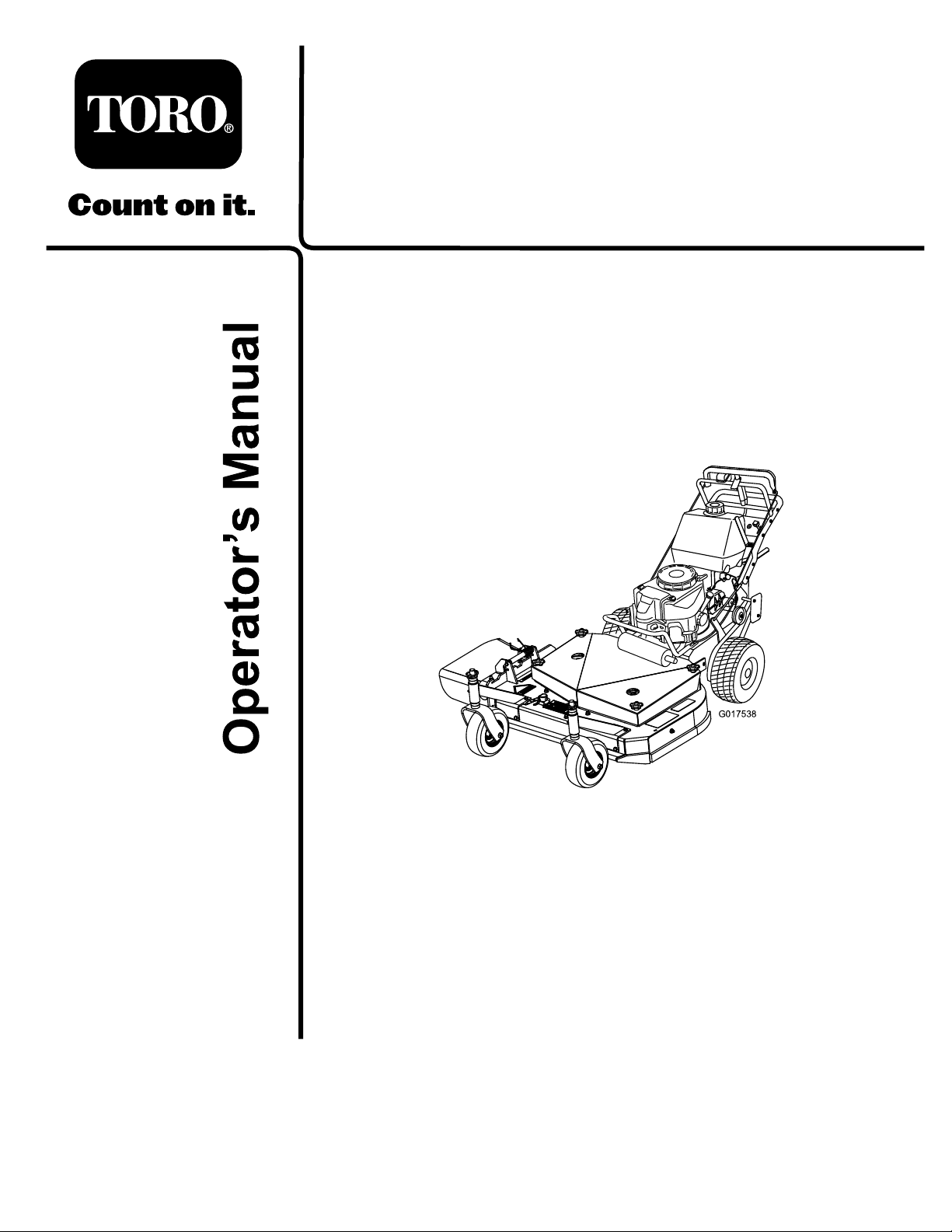
CommercialWalk-BehindMower
FixedDeck,T-Bar,GearDrivewith48in
TURBOFORCE
ModelNo.39678—SerialNo.315000001andUp
®
CuttingUnit
Registeratwww.T oro.com.
OriginalInstructions(EN)
*3392-709*A
Page 2
WARNING
CALIFORNIA
Proposition65Warning
Thisproductcontainsachemicalorchemicals
knowntotheStateofCaliforniatocausecancer,
birthdefects,orreproductiveharm.
Theengineexhaustfromthisproduct
containschemicalsknowntotheStateof
Californiatocausecancer,birthdefects,
orotherreproductiveharm.
operators.Itisdesignedprimarilyforcuttinggrasson
well-maintainedlawnsonresidentialorcommercial
properties.Itisnotdesignedforcuttingbrushorfor
agriculturaluses.
Readthisinformationcarefullytolearnhowtooperateand
maintainyourproductproperlyandtoavoidinjuryand
productdamage.Youareresponsibleforoperatingthe
productproperlyandsafely.
YoumaycontactTorodirectlyatwww .T oro.comforproduct
andaccessoryinformation,helpndingadealer,ortoregister
yourproduct.
ThissparkignitionsystemcomplieswithCanadianICES-002.
Becauseinsomeareastherearelocal,state,orfederal
regulationsrequiringthatasparkarresterbeusedonthe
engineofthismachine,asparkarresterisincorporatedwith
themuferassembly.
GenuineT orosparkarrestersareapprovedbytheUSDA
ForestryService.
Important:Thisengineisequippedwithaspark
arrestermufer.ItisaviolationofCaliforniaPublic
ResourceCodeSection4442touseoroperatetheengine
onanyforest-covered,brush-covered,orgrass-covered
landwithoutasparkarrestermufermaintainedin
workingorder,ortheengineconstricted,equipped,and
maintainedforthepreventionofre.Otherstatesor
federalareasmayhavesimilarlaws.
WARNING
Removingstandardoriginalequipmentpartsand
accessoriesmayalterthewarranty,traction,and
safetyofthemachine.FailuretouseoriginalToro
partscouldcauseseriousinjuryordeath.Making
unauthorizedchangestotheengine,fuelorventing
system,mayviolateEPAandCARBregulations.
Replaceallpartsincluding,butnotlimitedto,tires,
belts,blades,andfuelsystemcomponentswith
originalToroparts.
Wheneveryouneedservice,genuineT oroparts,oradditional
information,contactanAuthorizedServiceDealerorToro
CustomerServiceandhavethemodelandserialnumbersof
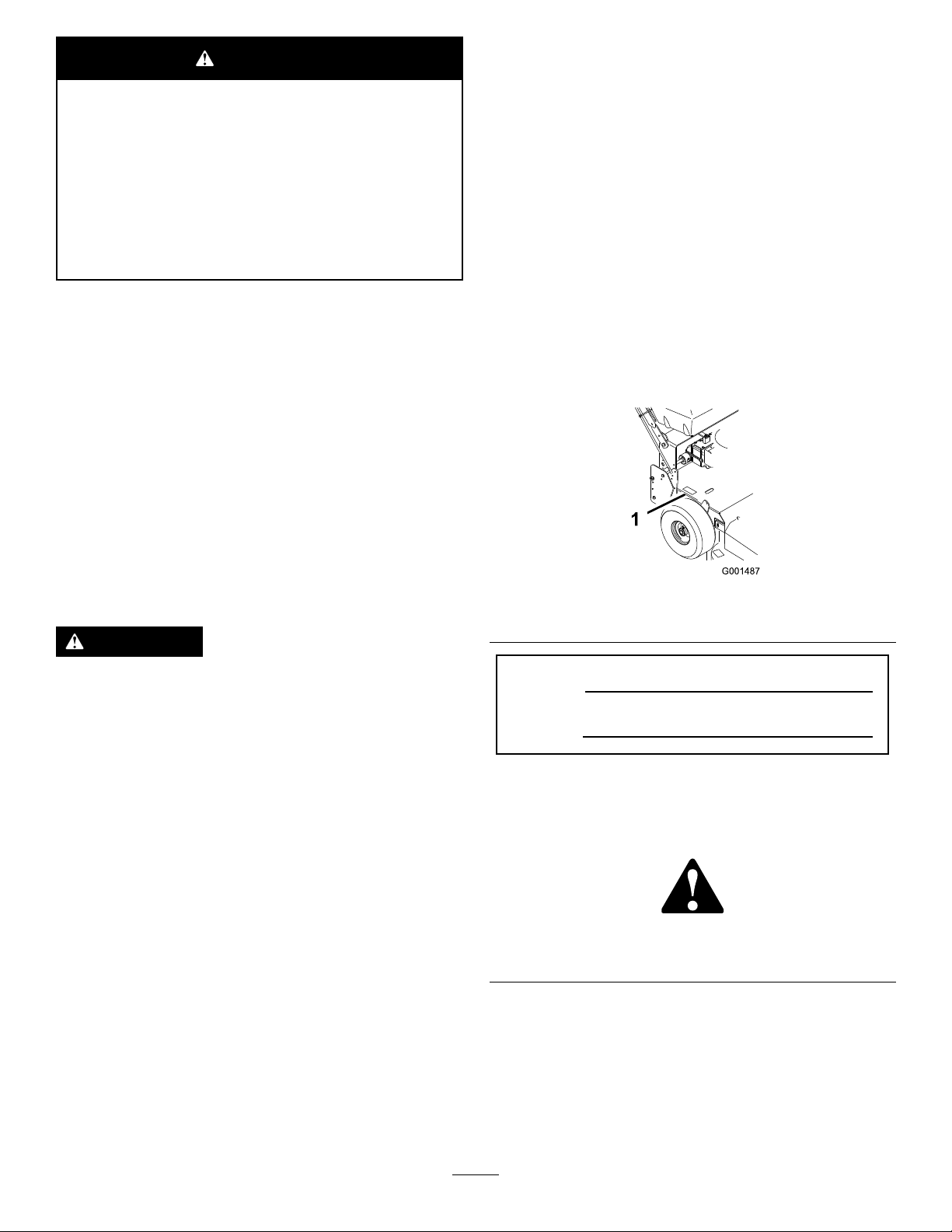
yourproductready.Figure1identiesthelocationofthe
modelandserialnumbersontheproduct.Writethenumbers
inthespaceprovided.
Figure1
1.Modelandserialnumberlocation
ModelNo.
SerialNo.
Thismanualidentiespotentialhazardsandhassafety
messagesidentiedbythesafetyalertsymbol(Figure2),
whichsignalsahazardthatmaycauseseriousinjuryordeath
ifyoudonotfollowtherecommendedprecautions.
Theenclosed
informationregardingtheUSEnvironmentalProtection
Agency(EPA)andtheCaliforniaEmissionControl
Regulationofemissionsystems,maintenance,and
warranty.Replacementsmaybeorderedthroughthe
enginemanufacturer.
Engine Owner's Man ual
issuppliedfor
Introduction
Thisrotary-blade,lawnmowerisintendedtobeused
byresidentialhomeownersorprofessional,hired
©2014—TheToro®Company
8111LyndaleAvenueSouth
Bloomington,MN55420
Figure2
1.Safetyalertsymbol
Thismanualuses2wordstohighlightinformation.
Importantcallsattentiontospecialmechanicalinformation
andNoteemphasizesgeneralinformationworthyofspecial
attention.
Contactusatwww.Toro.com.
2
PrintedintheUSA
AllRightsReserved
Page 3

Contents
Safety...........................................................................4
SafeOperatingPractices...........................................4
ToroMowerSafety..................................................5
SlopeIndicator.......................................................7
SafetyandInstructionalDecals.................................8
ProductOverview.........................................................12
Controls...............................................................12
Specications........................................................13
Attachments/Accessories........................................13
Operation....................................................................14
AddingFuel...........................................................14
UsingFuelStabilizer/Conditioner............................14
FillingtheFuelTank...............................................15
CheckingtheEngine-OilLevel.................................15
PuttingSafetyFirst.................................................15
OperatingtheParkingBrake....................................15
StartingandStoppingtheEngine..............................15
OperatingtheBlade-ControlLever(PTO).................16
TheSafety-InterlockSystem....................................17
DrivingForwardorBackward..................................17
UsingtheLowerControlBar...................................17
StoppingtheMachine.............................................18
TransportingtheMachine........................................18
AdjustingtheFlowBafe........................................19
PositioningtheFlowBafe......................................19
SideDischargingorMulchingtheGrass.....................20
AdjustingtheHeightofCut.....................................20
AdjustingtheHandleHeight....................................21
AdjustingtheControlRods......................................22
Height-of-CutChart...............................................23
Maintenance.................................................................24
RecommendedMaintenanceSchedule(s)......................24
Lubrication...............................................................25
LubricatingtheMachine..........................................25
LubricatingtheCasterandWheelBearings.................25
GreasingtheTransmissionCouplers.........................25
GreasingtheMowerBeltIdler..................................25
EngineMaintenance..................................................26
ServicingtheAirCleaner.........................................26
ServicingtheEngineOil..........................................26
ServicingtheSparkPlugs.........................................28
FuelSystemMaintenance...........................................29
ServicingtheFuelSystem........................................29
DriveSystemMaintenance.........................................31
CheckingtheTirePressure......................................31
CoolingSystemMaintenance......................................31
CleaningtheAir-IntakeScreen.................................31
CleaningtheCoolingSystem....................................31
BrakeMaintenance....................................................32
ServicingtheBrakes................................................32
BeltMaintenance......................................................33
CheckingtheBelts..................................................33
ReplacingtheTractionDriveBelt.............................33
ReplacingtheDriveBelt..........................................33
ReplacingtheMowerBelt........................................33
AdjustingtheMowerBeltTension............................34
AdjustingthePTOEngagementLinkage...................36
AdjustingthePTOSafetySwitch..............................36
MowerDeckMaintenance...........................................37
ServicingtheCuttingBlades.....................................37
AdjustingtheBladeBrake........................................40
ReplacingtheGrassDeector..................................40
Storage........................................................................41
Troubleshooting...........................................................42
Schematics...................................................................44
3
Page 4

Safety
Note:Theadditionofattachmentsmadebyother
manufacturersthatdonotmeetAmericanNationalStandards
Institutecerticationwillcausenoncomplianceofthis
machine.
Improperlyusingormaintainingthemachinecanresult
ininjury.Toreducethepotentialforinjury,complywith
thesesafetyinstructionsandalwayspayattentiontothe
safetyalertsymbol,whichmeans
Danger
withtheinstructionmayresultinpersonalinjuryor
death.
—personalsafetyinstruction.Failuretocomply
SafeOperatingPractices
ThefollowinginstructionsareadaptedfromANSI
B71.4-2012.
Training
•ReadtheOperator'sManualandothertrainingmaterial.If
theoperator(s)ormechanic(s)cannotreadorunderstand
theinformationitistheowner'sresponsibilitytoexplain
thismaterialtothem.
•Becomefamiliarwiththesafeoperationoftheequipment,
operatorcontrols,andsafetysigns.
•Alloperatorsandmechanicsshouldbetrained.The
ownerisresponsiblefortrainingtheusers.
•Neverletchildrenoruntrainedpeopleoperateorservice
theequipment.Localregulationsmayrestricttheageof
theoperator.
•Theowner/usercanpreventandisresponsiblefor
accidentsorinjuriesoccurringtopeopleordamageto
property.
Preparation
•Evaluatetheterraintodeterminewhataccessoriesand
attachmentsareneededtoproperlyandsafelyperform
thejob.Useonlyaccessoriesandattachmentsapproved
bythemanufacturer.
•Wearappropriateclothingincludinghardhat,substantial,
slip-resistantfootwear,safetyglasses,andhearing
protection.Longhair,looseclothing,orjewelrymayget
tangledinmovingparts.
•Inspecttheareawheretheequipmentistobeusedand
removeallobjectssuchasrocks,toys,andwire,whichcan
bethrownbythemachine.
•Checkthatoperator'spresencecontrols,safetyswitches,
andshieldsareattachedandfunctioningproperly.Donot
operateunlesstheyarefunctioningproperly.
Caution, W ar ning ,
Operation
•Lightningcancausesevereinjuryordeath.Iflightning
isseenorthunderisheardinthearea,donotoperate
themachine;seekshelter.
•Neverrunanengineinanenclosedarea.
•Operatethemachineonlyingoodlight,keepingaway
fromholesandhiddenhazards.
•Besurethatalldrivesareinneutralandtheparkingbrake
or
isengagedbeforestartingtheengine.Starttheengine
onlyfromtheoperator'sposition.
•Besureofyourfootingwhileusingthismachine,
especiallywhenbackingup.Walk;donotrun.Never
operateonwetgrass.Reducedfootingcouldcause
slipping.
•Slowdownanduseextracareonhillsides.Besureto
travelsidetosideonhillsides.Turfconditionscanaffect
thestabilityofthemachine.Usecautionwhileoperating
neardrop-offs.
•Slowdownandusecautionwhenmakingturnsandwhen
changingdirectiononslopes.
•Neverraisethedeckwiththebladesrunning.
•NeveroperatewiththePTOshieldorotherguardsnot
securelyinplace.Besureallinterlocksareattached,
adjustedproperly ,andfunctioningproperly.
•Neveroperatewiththedischargedeectorraised,
removedoraltered,unlessyouareusingagrasscatcher.
•Donotchangetheenginegovernorsettingoroverspeed
theengine.
•Stoponlevelground,disengagedrives,engagethe
parkingbrake(ifprovided),andshutofftheenginebefore
leavingtheoperator'spositionforanyreason,including
emptyingthecatchersoruncloggingthechute.
•Stoptheequipmentandinspectthebladesafterstriking
objectsorifanabnormalvibrationoccurs.Make
necessaryrepairsbeforeresumingoperation.
•Keephandsandfeetawayfromthecuttingunit.
•Lookbehindanddownbeforebackinguptobesureof
aclearpath.
•Nevercarrypassengersonthemachine.
•Keeppetsandbystandersaway .
•Slowdownandusecautionwhenmakingturnsand
crossingroadsandsidewalks.Stopthebladesifyouare
notmowing.
•Beawareofthemowerdischargedirectionanddonot
pointitatanyone.
•Donotoperatethemowerundertheinuenceofalcohol
ordrugs.
•Usecarewhenloadingorunloadingthemachineinto
orfromatrailerortruck.
•Usecarewhenapproachingblindcorners,shrubs,trees,
orotherobjectsthatmayobscurevision.
4
Page 5

SafeHandlingofFuels
•Toavoidpersonalinjuryorpropertydamage,use
extremecareinhandlinggasoline.Gasolineisextremely
ammableandthevaporsareexplosive.
•Extinguishallcigarettes,cigars,pipes,andothersources
ofignition.
•Useonlyanapprovedfuelcontainer.
•Neverremovethefuelcaporaddfuelwiththeengine
running.
•Allowtheenginetocoolbeforerefueling.
•Neverrefuelthemachineindoors.
•Neverstorethemachineorfuelcontainerwherethereis
anopename,spark,orpilotlight,suchasonawater
heateroronotherappliances.
•Neverllcontainersinsideavehicleoronatruckor
trailerbedwithaplasticliner.Alwaysplacecontainerson
theground,awayfromyourvehiclebeforelling.
•Removeequipmentfromthetruckortrailerandrefuel
itontheground.Ifthisisnotpossible,refuelsuch
equipmentwithaportablecontainerratherthanfroma
fueldispensernozzle.
•Keepthenozzleincontactwiththerimofthefueltank
orcontaineropeningatalltimesuntilfuelingiscomplete.
•Donotuseanozzlelock-opendevice.
•Iffuelisspilledonclothing,changetheclothing
immediately.
•Neveroverllfueltank.Replacethefuelcapandtighten
itsecurely.
•Keephandsandfeetawayfrommovingparts.Ifpossible,
donotmakeadjustmentswiththeenginerunning.
•Keepallpartsingoodworkingconditionandallhardware
tightened.Replaceallwornordamageddecals.
•Tobestprotectyourinvestmentandmaintainoptimal
performanceofyourToroequipment,countonT oro
genuineparts.Whenitcomestoreliability,Torodelivers
replacementpartsdesignedtotheexactengineering
specicationsofourequipment.Forpeaceofmind,insist
onTorogenuineparts.
Hauling
•Usecarewhenloadingorunloadingthemachineintoa
trailerortruck.
•Usefull-widthrampsforloadingmachineintotraileror
truck.
•Tiethemachinedownsecurelyusingstraps,chains,cable,
orropes.Bothfrontandrearstrapsshouldbedirected
downandoutwardfromthemachine.
ToroMowerSafety
ThefollowinglistcontainssafetyinformationspecictoToro
productsandothersafetyinformationyoumustknow .
Thisproductisdesignedforcuttingandrecyclinggrassor,
whenequippedwithagrassbagger,forcatchingcutgrass.
Anyuseforpurposesotherthanthesecouldprovedangerous
toyouandbystanders.
MaintenanceandStorage
•Disengagedrives,settheparkingbrake,stoptheengine
andremovethekeyordisconnectthespark-plugwire.
Waitforallmovementtostopbeforeadjusting,cleaning,
orrepairingthemachine.
•Cleangrassanddebrisfromthecuttingunit,thedrives,
themufers,andtheenginetohelppreventres.Clean
upoilorfuelspills.
•Lettheenginecoolbeforestoring,anddonotstoreit
nearaame.
•Shutoffthefuelwhilestoringortransportingthe
machine.Donotstorefuelnearamesordrainitindoors.
•Parkthemachineonlevelground.Settheparkingbrake.
Neverallowuntrainedpersonneltoservicethemachine.
•Usejackstandstosupportcomponentswhenrequired.
•Carefullyreleasepressurefromcomponentswithstored
energy.
•Disconnectthebatteryorthespark-plugwirebefore
makinganyrepairs.Disconnectthenegativeterminal
rstandthepositivelast.Connectthepositiverstand
negativelast.
•Usecarewhencheckingtheblades.Wraptheblade(s)or
weargloves,andusecautionwhenservicingthem.Only
replaceblades.Neverstraightenorweldthem.
GeneralOperation
•Besurethattheareaisclearofotherpeoplebefore
mowing.Stopthemachineifanyoneentersthearea.
•Donottouchequipmentorattachmentpartswhich
maybehotfromoperation.Allowthemtocoolbefore
attemptingtomaintain,adjust,orservicethem.
•UseonlyT oroapprovedattachments.Thewarranty
maybevoidedifyouusethemachinewithunapproved
attachments.
•Checkcarefullyforoverheadclearances(i.e.branches,
doorways,electricalwires)beforeoperatingthemachine
underanyobjects,anddonotcontactthem.
SlopeOperation
Allslopesandrampsrequireextracaution.Ifyoufeeluneasy
onaslope,donotmowit.
•Removeobstaclessuchasrocks,treelimbs,etc.fromthe
mowingarea.
•Watchforholes,ruts,orbumps.Tallgrasscanhide
obstacles.
•Usecautionneardrop-offs,ditches,orembankments.
Themachinecouldsuddenlyturnoverifawheelgoes
overtheedgeofaclifforditch,orifanedgecavesin.
5
Page 6

•Useextracarewithgrasscatchersorotherattachments.
Thesecanchangethestabilityofthemachine.
•Keepallmovementonslopesslowandgradual.Donot
makesuddenchangesinspeedordirection.
•Mowslopessidetoside.
•Donotmowslopesgreaterthan20degrees.
Service
•Neverstorethemachineorfuelcontainerinsidewhere
thereisanopename,suchasnearawaterheateror
furnace.
•Keepnutsandboltstight,especiallythebladeattachment
bolts.Keepequipmentingoodcondition.
•Nevertamperwithsafetydevices.Checksafetysystems
forproperoperationbeforeeachuse.
•Useonlygenuinereplacementpartstoensurethatoriginal
standardsaremaintained.
•Checkbrakeoperationfrequently.Adjustandserviceas
required.
6
Page 7
SlopeIndicator
G011841
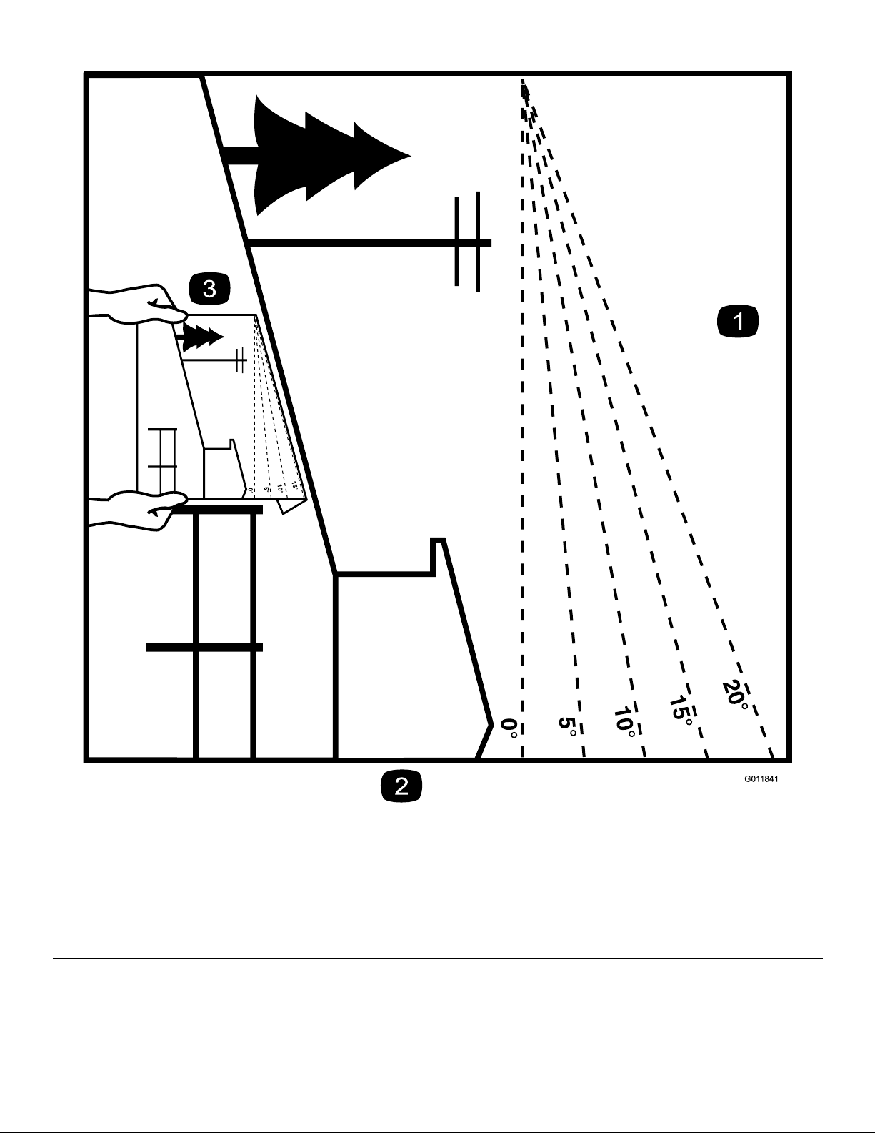
Figure3
Thispagemaybecopiedforpersonaluse.
1.Themaximumslopeyoucansafelyoperatethemachineonis20degrees.Usetheslopecharttodeterminethedegreeofslope
ofhillsbeforeoperating.Donotoperatethismachineonaslopegreaterthan20degrees.Foldalongtheappropriateline
tomatchtherecommendedslope.
2.Alignthisedgewithaverticalsurface,atree,building,fencepole,etc.
3.Exampleofhowtocompareslopewithfoldededge.
7
Page 8
SafetyandInstructionalDecals
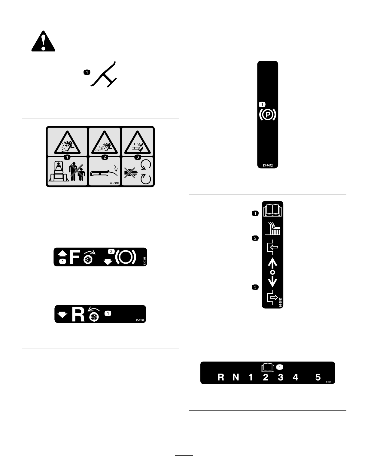
Safetydecalsandinstructionsareeasilyvisibletotheoperatorandarelocatednearanyareaofpotential
danger.Replaceanydecalthatisdamagedorlost.
Manufacturer'sMark
1.Indicatesthebladeisidentiedasapartfromtheoriginal
machinemanufacturer.
93-7010
93-7442
1.Parkingbrake
1.Thrownobjecthazard—keepbystandersasafedistance
fromthemachine.
2.Thrownobjecthazard,mower—keepthedeectorinplace.
3.Cutting/dismembermentofhandorfoot—stayawayfrom
movingparts.
93-7298
1.Tractiondrive—forward
2.Pulltobrake
93-7299
1.Tractiondrive—reverse
1.ReadtheOperator's
Manualforinstructionson
operatingthecuttingblade
2.Pushforwardtoengage
95-5537
3.Pullbacktodisengage
1.ReadtheOperator'sManual.
8
98-3264
Page 9
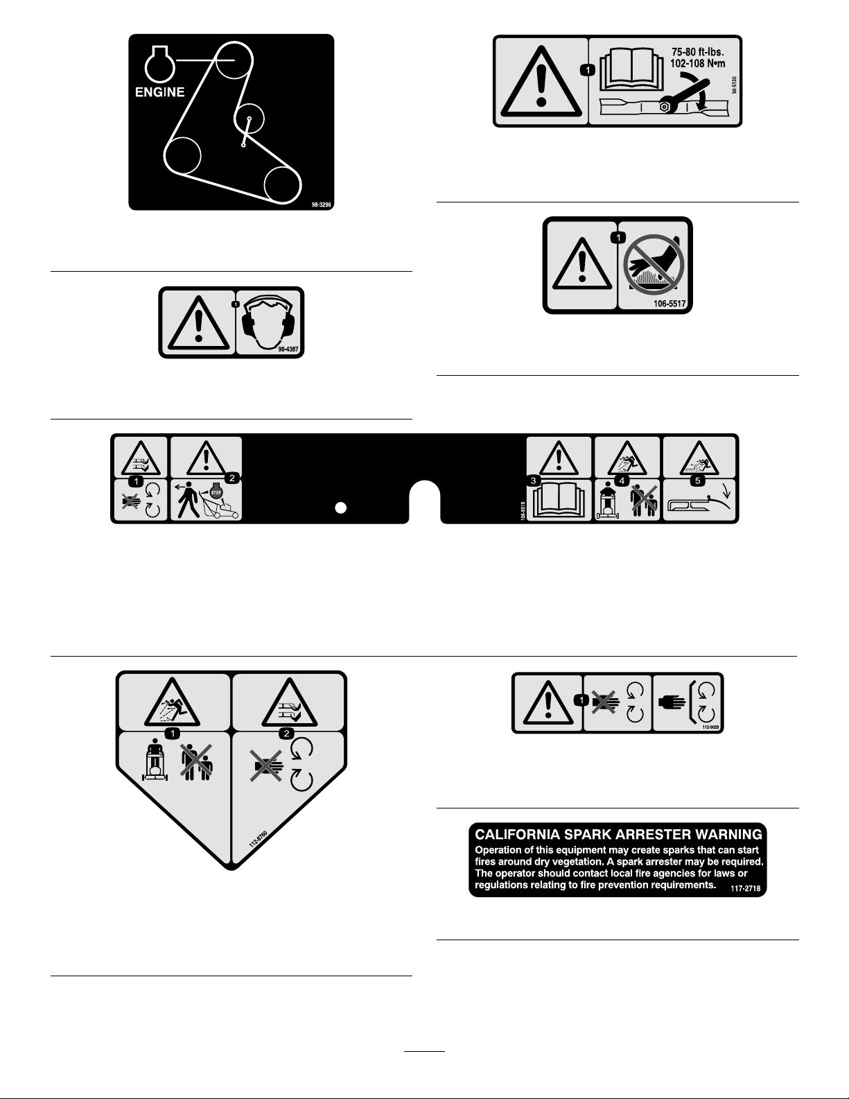
ForModelswith2–BladeMowerDecks
1.Warning—wearhearingprotection.
98-5130
1.Warning—readtheOperator'sManualforinstructionson
torquingthebladebolt/nutto75-80ft-lb(102-106N⋅m).
98-3296
106-5517
1.Warning—donottouchthehotsurface.
98-4387
106-5519
1.Severinghazardofhandorfoot,mower
blade—stayawayfrommovingparts.
2.Warning—releasethebarandensure
theenginehasstoppedbeforewalking
awayfromthemachine.
3.Warning—readtheOperator'sManual.
4.Thrownobjecthazard—keep
bystandersawayfromthemachine.
112-8760
1.Thrownobjecthazard—keepbystandersasafedistance
fromthemachine.
2.Cutting/dismembermentofhandorfoot—stayawayfrom
movingparts.
5.Thrownobjecthazard,raised
bafe—lowerthebafebeforeusing
themachine.
112-9028
1.Warning—stayawayfrommovingparts;keepallguardsin
place.
117–2718
9
Page 10
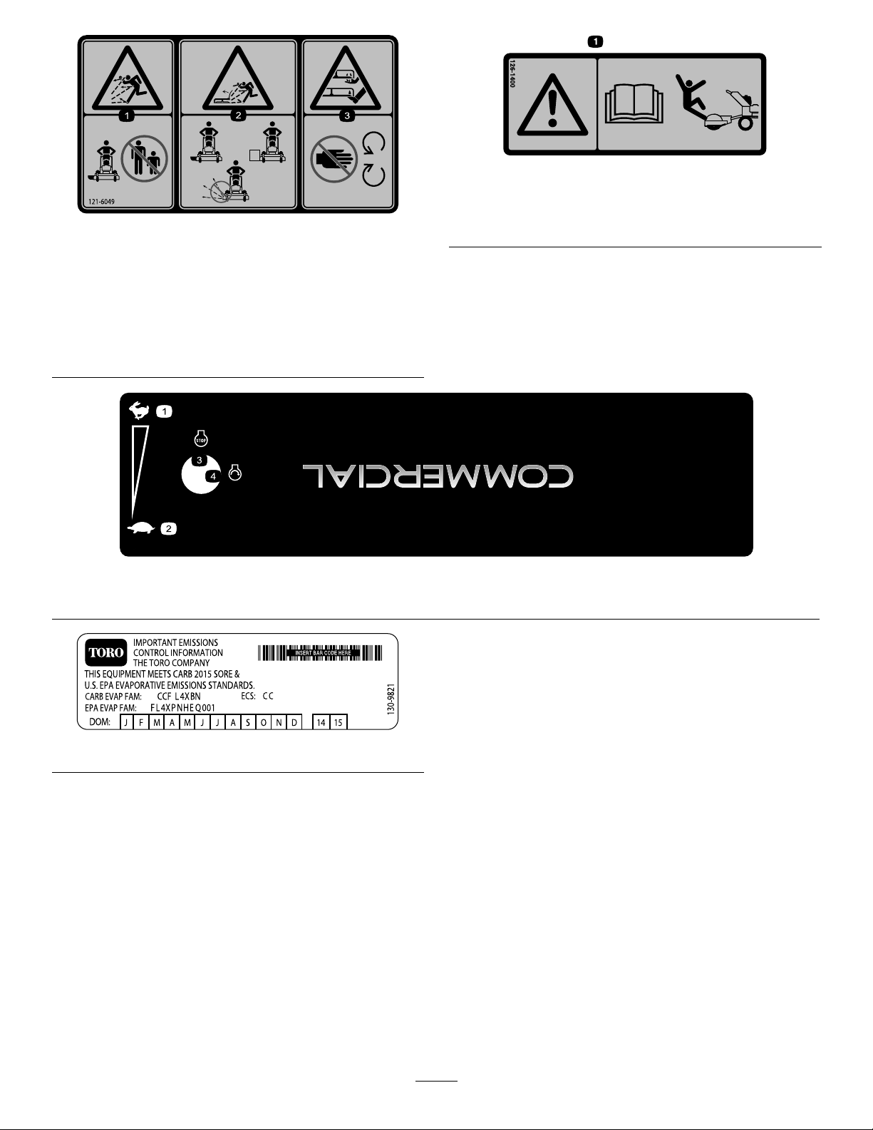
126-1400
1.Warning—ReadtheOperator’sManual.UseonlyT oro
ridingattachments.Useofotherridingattachmentsmay
121-6049
createahazardousconditionresultingininjury.
1.Thrownobject
hazard—keepbystanders
awayfromthemachine.
2.Thrownobjecthazard,
mower—donotoperate
themowerwithguardsor
shieldsremoved.
1.Fast
3.Cutting/dismemberment
hazardofhandorfoot,
mowerblade—keephands
awayfrommovingparts.
2.Slow
130-8374
3.Engine—stop4.Engine—slow
130-9821
10
Page 11
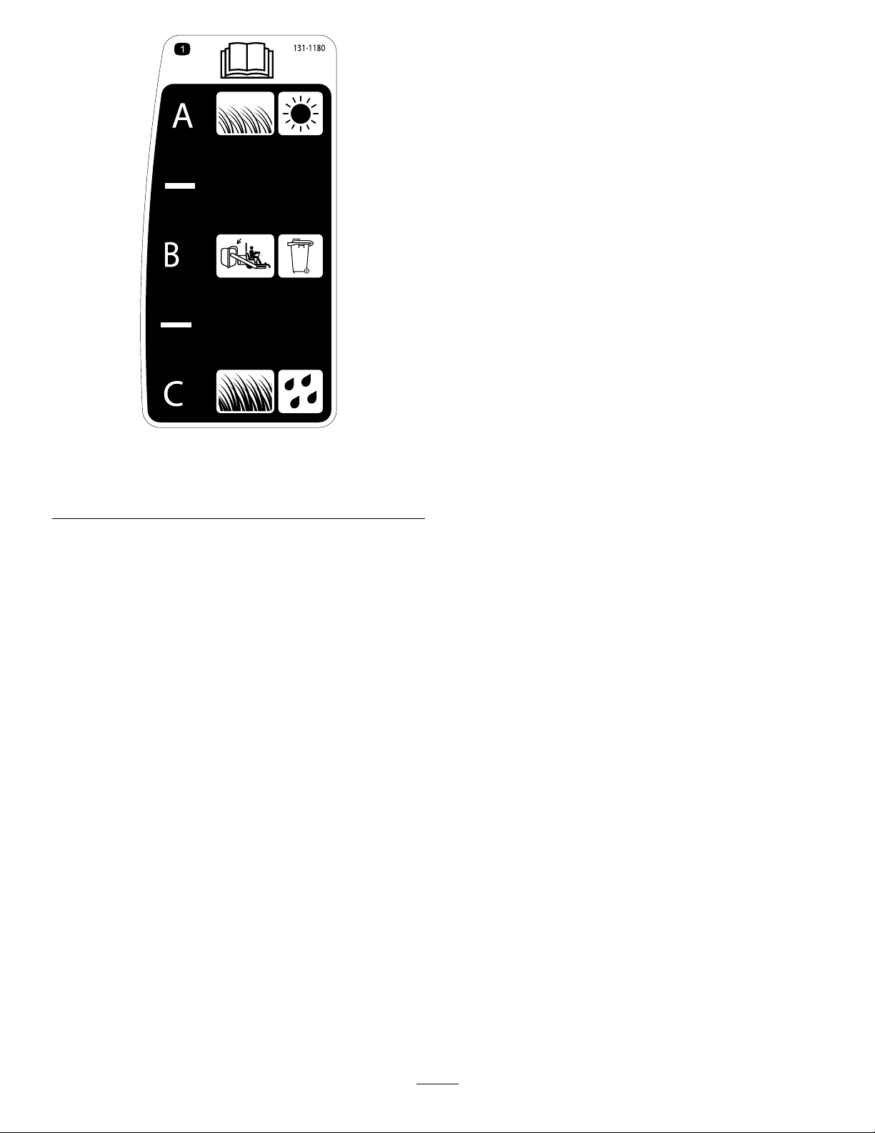
131-1180
1.ReadtheOperator'sManual.(A)Short,lightgrass;dry
conditions;maximumdispersion;(B)Baggingsetting;(C)
Tall,densegrass;wetconditions;maximumgroundspeed
11
Page 12
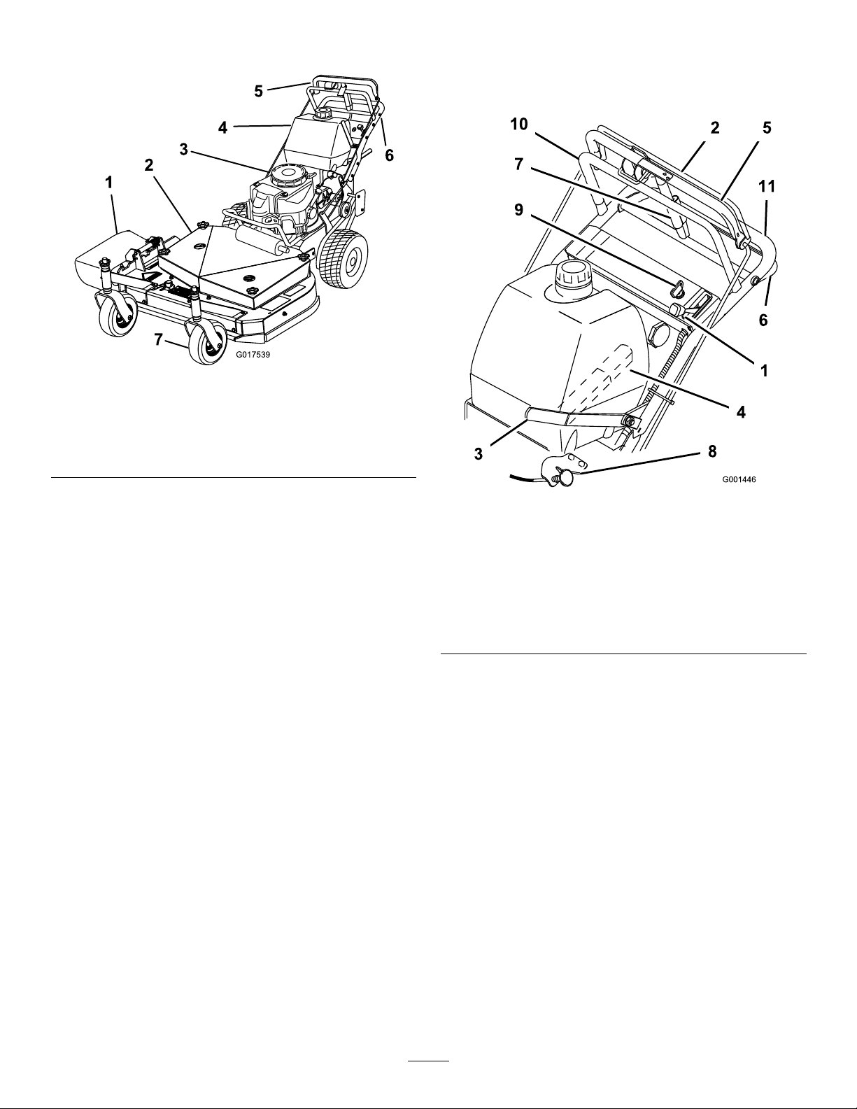
ProductOverview
G017539
Controls
Becomefamiliarwithallthecontrols(Figure5)beforeyou
starttheengineandoperatethemachine.
Figure4
1.Sidedischarge
2.Mowerdeck6.Handle
3.Recoil-starthandle7.Frontcasterwheel
4.Gastank
5.T-barcontrol
Figure5
1.Throttlecontrol7.Parkingbrake
2.Blade-controlbail
3.Powertake-offlever(PTO)
4.Gear-shiftlever
5.Uppercontrolbar11.Lowerhandle
6.Lowercontrolbar
lever—releasedposition
8.Choke
9.Ignitionswitch
10.Upperhandle
ThrottleControl
Thethrottlecontrolhas2positions:FastandSlow.
Blade-ControlBail
Thebailisusedinconjunctionwiththeblade-controllever
(PTO)toengagetheclutchanddrivethemowerblades.
Releasingthebladecontrolbailwillstoptheenginewiththe
PTOengaged.
Blade-ControlLever(PTO)
Thisleverisusedinconjunctionwiththeblade-controlbail
toengageanddisengagethemowerdeckbeltanddrivethe
mowerblades.
Gear-ShiftLever
Thetransmissionhas5forwardspeeds,neutral,andreverse,
andhasanin-lineshiftpattern.
12
Page 13

Important:Donotshiftwhilethemachineismoving,
astransmissiondamagemayoccur.
UpperControlBar
Shifttothedesiredgearandpushforwardontheupper
controlbarandbladecontrolbailtoengageforwardtraction
operationandpullbacktobrakeforwardmovement.Pull
backonrightsideofuppercontrolbartoturnrightandleft
sidetoturnleft.
Specications
Note:Specicationsanddesignaresubjecttochange
withoutnotice.
Widthwithdeectordown161cm(63-1/2inches)
Length
Height
Weight
184cm(72inches)
104cm(41inches)
226kg(598lb)
LowerControlBar
Shifttransmissiontoreverseandsqueezethelowercontrol
barandhandletogethertoengagetherearwardtractionassist.
Parking-BrakeLever
Pullbackonuppercontrolbarandswingbrakeleverup
againsttheupperhandletosettheparkingbrake(Figure5).
IgnitionSwitch
Thisswitchisusedinconjunctionwithrecoilstarterandhas
twopositions:RunandOff.
Recoil-StartHandle
Pulltherecoil-starthandletostarttheengine(notshown
inFigure4).
Fuel-ShutoffValve
Closethefuel-shutoffvalvewhentransportingorstoringthe
machine.
Attachments/Accessories
AselectionofToroapprovedattachmentsandaccessoriesis
availableforusewiththemachinetoenhanceandexpand
itscapabilities.ContactyourAuthorizedServiceDealeror
Distributororgotowww .Toro.comforalistofallapproved
attachmentsandaccessories.
Choke
Usethechoketostartacoldengine.
13
Page 14

Operation
AddingFuel
•Forbestresults,useonlyclean,fresh(lessthan30days
old),unleadedgasolinewithanoctaneratingof87or
higher((R+M)/2ratingmethod).
•Ethanol:Gasolinewithupto10%ethanol(gasohol)
or15%MTBE(methyltertiarybutylether)byvolume
isacceptable.EthanolandMTBEarenotthesame.
Gasolinewith15%ethanol(E15)byvolumeisnot
approvedforuse.Neverusegasolinethatcontainsmore
than10%ethanolbyvolume,suchasE15(contains15%
ethanol),E20(contains20%ethanol),orE85(contains
85%ethanol).Usingunapprovedgasolinemaycause
performanceproblemsand/orenginedamagewhichmay
notbecoveredunderwarranty.
•Donotusegasolinecontainingmethanol.
•Donotstorefueleitherinthefueltankorfuelcontainers
overthewinterunlessafuelstabilizerisused.
•Donotaddoiltogasoline.
DANGER
DANGER
Incertainconditionsduringfueling,static
electricitycancauseaspark,whichcanignitethe
fuelvapors.Areorexplosionfromfuelcanburn
youandothersandcandamageproperty.
•Alwaysplacefuelcontainersonthegroundaway
fromyourvehiclebeforelling.
•Donotllfuelcontainersinsideavehicleoron
atruckortrailerbedbecauseinteriorcarpets
orplastictruck-bedlinersmayinsulatethe
containerandslowthelossofanystaticcharge.
•Whenpractical,removefuel-poweredequipment
fromthetruckortrailerandfueltheequipment
withitswheelsontheground.
•Ifthisisnotpossible,thenrefuelsuchequipment
onatruckortrailerfromaportablecontainer,
ratherthanfromafuel-dispensernozzle.
•Ifafueldispensermustbeused,keepthe
nozzleincontactwiththerimofthefueltank
orcontaineropeningatalltimesuntilfuelingis
complete.
Incertainconditions,fuelisextremelyammable
andhighlyexplosive.Areorexplosionfromfuel
canburnyouandothersandcandamageproperty.
•Fillthefueltankoutdoors,inanopenarea,when
theengineiscold.Wipeupanyfuelthatspills.
•Neverllthefueltankinsideanenclosedtrailer.
•Donotllthefueltankcompletelyfull.Addfuel
tothefueltankuntilthelevelis25mm(1inch)
belowthebottomofthellerneck.Thisempty
spaceinthetankallowsthefueltoexpand.
•Neversmokewhenhandlingfuel,andstayaway
fromanopenameorwherefuelfumesmaybe
ignitedbyaspark.
•Storefuelinanapprovedcontainerandkeepit
outofthereachofchildren.Donotbuymore
thana30-daysupplyoffuel.
•Donotoperatewithouttheentireexhaust
systeminplaceandinproperworkingcondition.
WARNING
Gasolineisharmfulorfatalifswallowed.Long-term
exposuretovaporscancauseseriousinjuryand
illness.
•Avoidprolongedbreathingofvapors.
•Keepfaceawayfromnozzleandgastankor
conditioneropening.
•Keepgasawayfromeyesandskin.
UsingFuel Stabilizer/Conditioner
Useafuelstabilizer/conditionerinthemachinetokeepthe
fuelfreshduringstorageof90daysorless.Ifyouarestoring
themachineforlonger,drainthefueltank;refertoDraining
theFuelTank(page29).
Important:Donotusefueladditivescontaining
methanolorethanol.
Addthecorrectamountoffuelstabilizer/conditionertothe
fuel,andfollowthedirectionsofthemanufacturer.
Note:Fuelstabilizer/conditionerismosteffectivewhen
mixedwithfreshgasoline.Tominimizethechanceofvarnish
depositsinthefuelsystem,usefuelstabilizeratalltimes.
14
Page 15
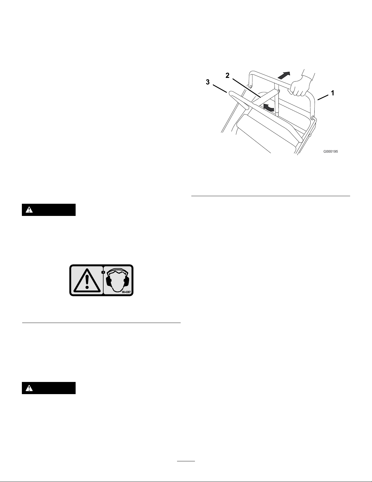
FillingtheFuelTank
1.Shuttheengineoffandsettheparkingbrake.
2.Cleanaroundthefuel-tankcapandremovethecap.
Addunleadedregulargasolinetothefueltank,untilthe
levelis6to13mm(1/4to1/2inch)belowthebottom
ofthellerneck.Thisspaceinthetankallowsgasoline
toexpand.Donotllthefueltankcompletelyfull.
3.Installthefuel-tankcapsecurely.Wipeupanygasoline
thatmayhavespilled.
CheckingtheEngine-OilLevel
Beforeyoustarttheengineandusethemachine,checktheoil
levelintheenginecrankcase;refertoCheckingtheEngine-oil
Level.
PuttingSafetyFirst
Carefullyreadallthesafetyinstructionsanddecalsinthe
safetysection.Knowingthisinformationcouldhelpyouor
anybystandersavoidinjury.
Theuseofprotectiveequipmentforeyes,hearing,feetand
headisrecommended.
SettingtheParkingBrake
1.Pulltheuppercontrolbarrearwardandholditinthis
position(Figure7).
2.Lifttheparking-brakelockupandgraduallyreleasethe
uppercontrolbar.Thebrakelockshouldstayintheset
(locked)position(Figure7).
Figure7
1.Uppercontrolbar3.Fixedbar
2.Parking-brakelever—set
position
CAUTION
Thismachineproducessoundlevelsinexcessof
85dBAattheoperator'searandcancausehearing
lossthroughextendedperiodsofexposure.
Wearhearingprotectionwhenoperatingthis
machine.
Figure6
1.Warning—wearhearingprotection.
OperatingtheParkingBrake
Stoponlevelground,disengagedrives,engagetheparking
brake,stoptheengine,andremovethekey .Alwaysset
theparkingbrakewhenyoustopthemachineorleaveit
unattended.
CAUTION
Childrenorbystandersmaybeinjuredifthey
moveorattempttooperatethemachinewhileitis
unattended.
Alwaysremovetheignitionkeyandsettheparking
brakewhenleavingthemachineunattended,even
ifjustforafewminutes.
ReleasingtheParkingBrake
1.Pullrearwardontheuppercontrolbar.Lowerthe
parking-brakelocktothereleasedposition.
2.Graduallyreleasetheuppercontrolbar.
StartingandStoppingthe Engine
StartingtheEngine
1.Connectthewirestothesparkplugs.
2.Openthefuelvalve.
3.Disengagetheblade-control(PTO)leverandmovethe
shiftlevertotheNeutralposition.
4.Settheparkingbrake.
5.TurntheignitionkeytotheRunposition(Figure8).
6.Tostartacoldengine,movethethrottlecontrol
midwaybetweentheFastandSlowpositions.
7.Tostartawarmengine,movethethrottlecontrolto
theFastposition.
8.PullthechokeknobtotheOnpositioniftheengineis
cold(Figure8).
Note:Awarmorhotengineusuallydoesnotrequire
usingthechoke.
9.Grasptherecoilstarterhandlermlyandpullitout
untilpositiveengagementresults;thenpullthehandle
vigorouslytostarttheengine.
15
Page 16
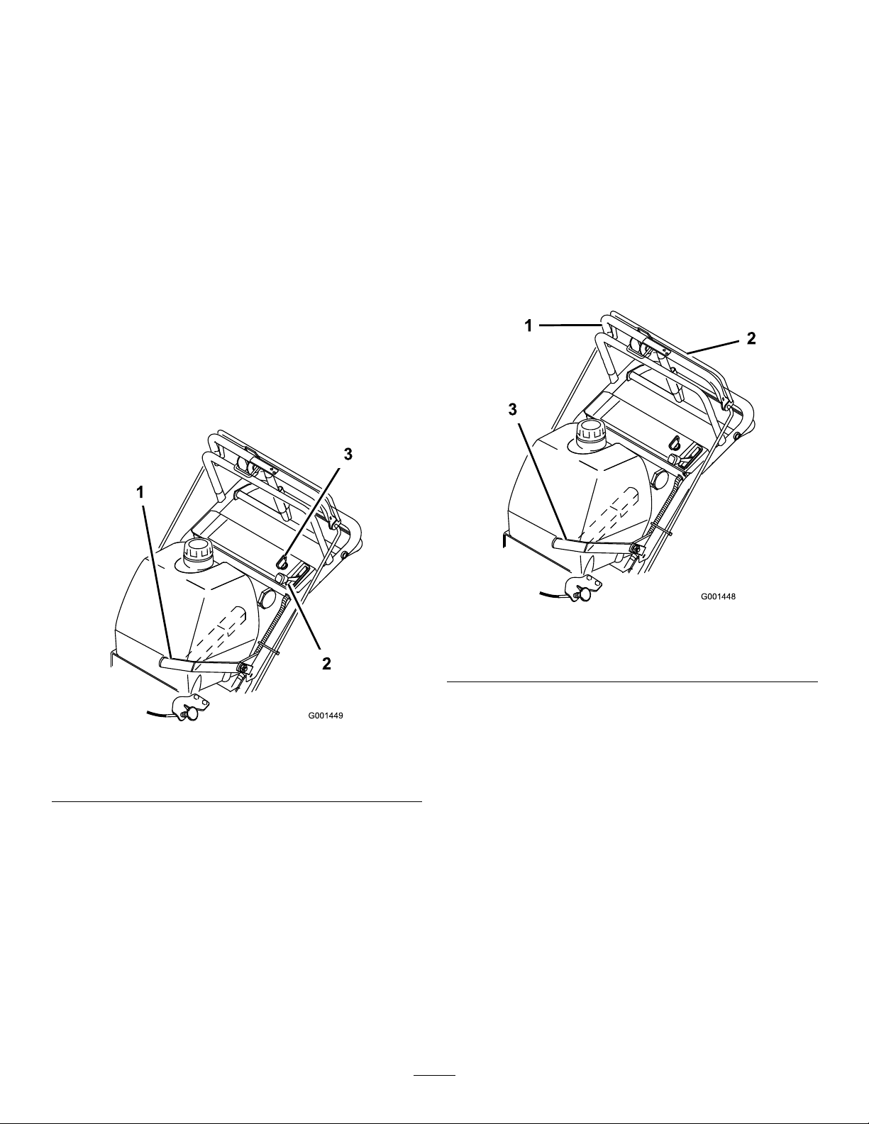
Note:Allowtheropetorecoilslowly.
Important:Donotpulltherecoilropetoitslimit
orreleasethestarterhandlewhenyoupullout
theropebecausetheropemaybreakortherecoil
assemblymaybedamaged.
10.PushthechoketotheOffpositionastheengine
warmsup.
OperatingtheBlade-Control Lever(PTO)
Theblade-controllever(PTO)engagesanddisengagespower
tothemowerblades.
EngagingtheMowerBlades
11.Iftheengineiscold,allowittowarmupandthen
movethethrottlecontroltotheFastposition.
StoppingtheEngine
Important:Inanemergency,youcanstoptheengine
immediatelybyturningtheignitionkeytotheOff
position.
1.MovethethrottlelevertotheSlowposition(Figure8).
2.Lettheengineidlefor30to60secondsbeforeturning
theignitionkeytotheOffposition.
3.TurntheignitionkeytotheOffposition(Figure8).
1.Toengagetheblades,squeezetheblade-controlbail
againsttheuppercontrolbar(Figure9).
2.Pushtheblade-controllever(PTO)rmlyforward,
untilitlatchesover-center.
3.Starttheengineandrepeattheproceduretoengagethe
mowerbladesiftheblade-controlbailisreleased.
Figure8
1.Blade-controllever(PTO)
2.Throttlelever
4.Settheparkingbrakeandremovethekey.
5.Disconnectthewiresfromthesparkplugstoprevent
thepossibilityofaccidentallystartingbeforestoringor
performingmaintenanceonthemachine.
6.Closethefuel-shutoffvalvebeforestoringor
transportingthemachine.
Important:Makesurethatthefuel-shutoff
valveisclosedbeforetransportingorstoringthe
machine,asfuelleakagemayoccur.
3.Ignitionkey
Figure9
1.Uppercontrolbar
2.Blade-controlbail
3.Blade-controllever(PTO)
DisengagingtheMowerBlades(PTO)
Todisengagetheblades,pulltheblade-controllever(PTO)
rearwardalltheway(Figure9).Theenginewillstopwhen
theblade-controlbailisreleasedwiththeblade-controllever
engaged.
Note:Itisnecessarytofullyandmanuallydisengagethe
blade-controllever.
16
Page 17
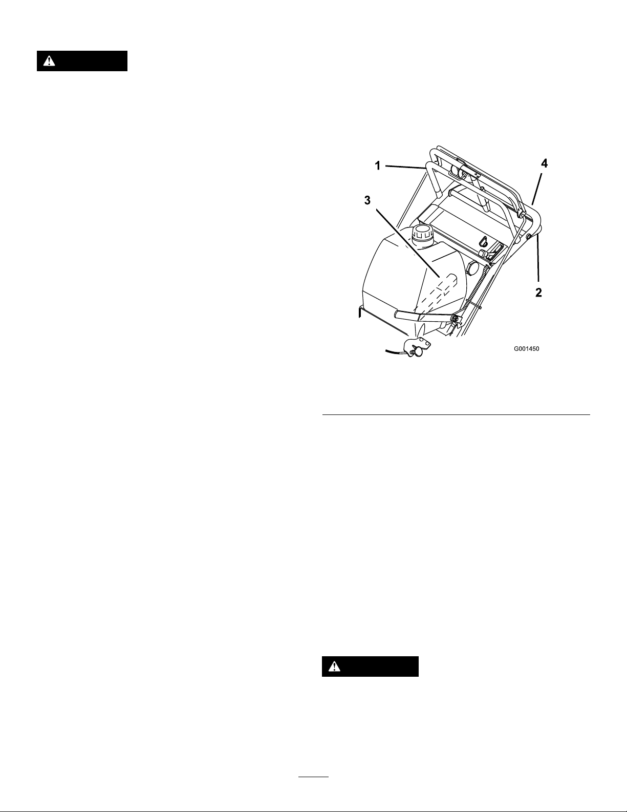
TheSafety-InterlockSystem
CAUTION
Ifsafety-interlockswitchesaredisconnectedor
damagedthemachinecouldoperateunexpectedly,
causingpersonalinjury.
•Donottamperwiththeinterlockswitches.
•Checktheoperationoftheinterlockswitches
daily,andreplaceanydamagedswitchesbefore
operatingthemachine.
Thesafety-interlocksystemisdesignedtopreventtheengine
fromstartingwhen:
•Theblade-controllever(PTO)isengaged.
•Theignitionkeyisintheoffposition.
Thesafety-interlocksystemisalsodesignedtostopthe
enginewhen:
•The-bladecontrolbailisreleasedwiththeblade-control
lever(PTO)engaged.
•Theignitionswitchisturnedtotheoffposition.
2.Releasetheparkingbrake;refertoReleasingthe
ParkingBrake(page15).
3.Slowlypressontheuppercontrolbartomoveforward
(Figure10).
Togostraight,applyequalpressuretobothendsofthe
uppercontrolbar(Figure10).
Toturn,releasepressureontheuppercontrolbarside
inthedirectionyouwanttoturn(Figure10).
TestingtheSafety-InterlockSystem
Testthesafety-interlocksystembeforeyouusethemachine
eachtime.Ifthesafetysystemdoesnotoperateasdescribed
below,haveanAuthorizedServiceDealerrepairthesafety
systemimmediately.
1.Settheparkingbrake,disengagethePTO,andplace
thethrottleforward.
2.Starttheengine.
3.Withtheenginerunningsqueezetheblade-control
bailagainstuppercontrolbarandpushthe
mower-blade-controlleverforward.
Note:Themowerbladesshouldbeginrotating.
4.Withtheenginerunning,releasetheblade-controlbail.
Note:Theengineshouldstop.
5.Starttheengineagain.
6.Withtheenginerunning,turntheignitionkeytothe
Offposition.
Note:Theengineshouldstop.
DrivingForwardorBackward
Figure10
1.Uppercontrolbar
2.Lowercontrolbar4.Lowerhandle
3.Shiftlever
DrivingBackward
1.Togobackward,movetheshiftlevertothereverse
gear.
2.Releasetheparkingbrake;refertoReleasingthe
ParkingBrake(page15).
3.Slowlysqueezethelowercontrolbarandlowerhandle
togethertomoverearward(Figure10).
UsingtheLowerControlBar
Thisprocedureisfordrivingupacurb.Thiscanbe
performedwhiledrivingforwardorbackward.
Note:Somecurbsdonotallowthereardrivetirestocontact
thecurb.Ifthishappens,drivethemachineupthecurbatan
angle.
Thethrottlecontrolregulatestheenginespeedasmeasured
inrpm(revolutionsperminute).Placethethrottlecontrolin
thefastpositionforbestmowingperformance.
DrivingForward
1.Togoforward,movetheshiftlevertoaforwardgear
(Figure10).
WARNING
Abladecanbebentordamagedwhendrivingup
acurb.Piecesofbladethatmaybethrowncould
seriouslyinjureorkillyouorbystanders.
Donotrunbladeswhiledrivingupacurbforward
orbackward.
17
Page 18
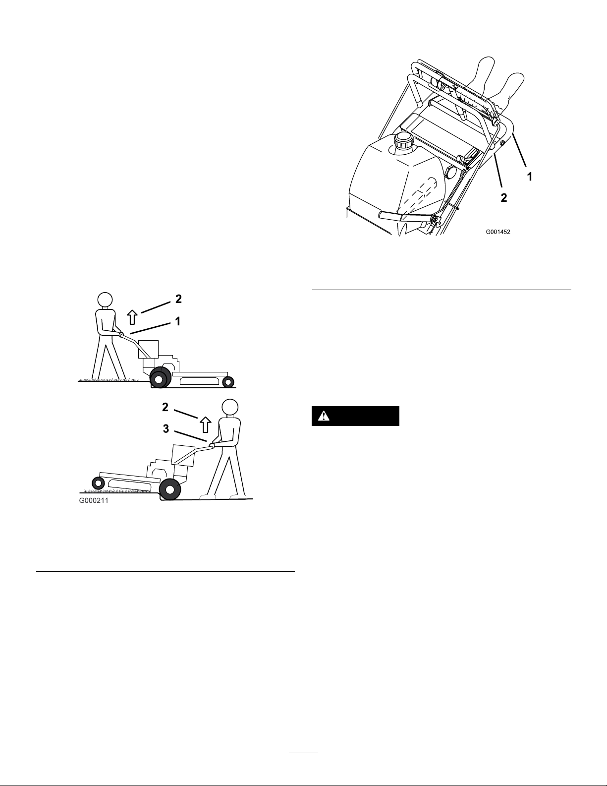
DrivingForwardupaCurb
1.Disengagethemowerblades.
2.Selecttherstgeartodrivethemachine.
3.Drivemachineuntilthecasterwheelscontactthecurb
(Figure11).
4.Liftthefrontofthemachinebypushingdownonthe
lowerhandle(Figure11).
5.Drivethemachineuntilthedrivewheelscontactthe
curb(Figure11).
6.Lowerthefrontofthemachine(Figure11).
Note:Bothdrivewheelsshouldcontactthecurband
casterwheelsstraight.
7.Atthesametimeengagethelowercontrolbarandlift
uponthelowerhandletodriveoverthecurb(Figure
10andFigure11).
Note:Liftinguponthelowerhandlewillassistdriving
themachineupacurbandnotspinthedrivewheels.
Figure12
Note:Liftinguponthelowerhandlewillassistdriving
themachineupacurbandnotspinthedrivewheels.
Figure11
1.Lowercontrolbarengaged
andmowerinreverse
2.Pulluptoassistmachine
3.Lowercontrolbarengaged
andmowergoingforward
DrivingBackwardupaCurb
1.Disengagethemowerblades.
2.Selectreversetodrivethemachine.
3.Drivethemachineuntildrivewheelscontactcurb
(Figure11).
Note:Bothdrivewheelsshouldcontactthecurband
casterwheelsstraight.
4.Atthesametimeengagelowercontrolbarandliftup
onthelowerhandle(Figure10andFigure12).
1.Lowercontrolbar
(engaged)
2.Handle
StoppingtheMachine
Tostopthemachine,pullbackontheuppercontrolbar,
releasetheblade-controlbail,turntheignitionkeytotheoff
position,andsettheparkingbrake;refertoOperatingthe
ParkingBrake(page15).Remembertoremovethekeyfrom
theignitionswitch.
CAUTION
Childrenorbystandersmaybeinjuredifthey
moveorattempttooperatethemachinewhileitis
unattended.
Alwaysremovetheignitionkeyandsettheparking
brakewhenleavingthemachineunattended,even
ifjustforafewminutes.
TransportingtheMachine
Useaheavy-dutytrailerortrucktotransportthemachine.
Ensurethatthetrailerortruckhasallnecessarylightingand
markingasrequiredbylaw.Pleasecarefullyreadallthesafety
instructions.Knowingthisinformationcouldhelpyou,your
family,petsorbystandersavoidinjury.
Totransportthemachine:
1.Stoptheengine,removethekey,setthebrake,and
closethefuelvalve.
2.Securelyfastenthemachinetothetrailerortruckwith
straps,chains,cable,orropes.
3.Ifusingatrailer,securethetrailertothetowingvehicle
andinstallthesafetychains.
18
Page 19
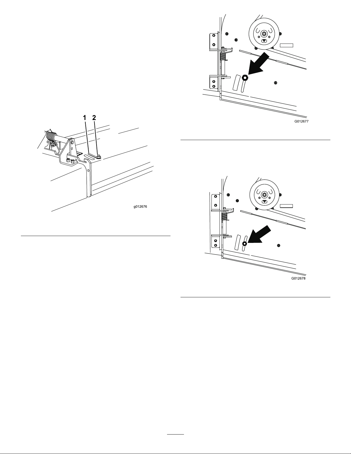
AdjustingtheFlowBafe
g012676
1 2
G012677
G012678
Youcanadjustthemowerdischargeowfordifferenttypes
ofmowingconditions.Positionthebafetogivethebest
qualityofcut.
1.DisengagethePTO,movethemotioncontrolleversto
theneutrallockedpositionandsettheparkingbrake.
2.Stoptheengine,removethekey,andwaitforallmoving
partstostopbeforeleavingtheoperatingposition.
3.Loosenthenut(Figure13).
4.Adjustthebafeandnutintheslottothedesired
dischargeow,andtightenthenut.
Figure14
PositionB
Usethispositionwhenbagging(Figure15).
Figure13
1.Slot
2.Nut
PositioningtheFlowBafe
Thefollowingguresareonlyrecommendationsforuse.
Adjustmentswillvarybygrasstype,moisturecontent,and
heightofgrass.
Note:Iftheenginepowerdrawsdownandthemower
groundspeedisthesame,openupthebafe.
PositionA
Thisisthefullrearposition(seeFigure14).Thesuggested
useforthispositionisafollows:
•Useforshort,lightgrassmowingconditions.
•Useindryconditions.
•Usetomakesmallergrassclippings.
•Usetopropelthegrassclippingsfartherawayfromthe
mower.
Figure15
PositionC
Thisisthefullopenposition.Thesuggesteduseforthis
positionisasfollows(Figure16):
•Useintall,densegrassmowingconditions.
•Useinwetconditions.
•Usetolowertheenginepowerconsumption.
•Useatincreasedgroundspeedinheavyconditions.
19
Page 20
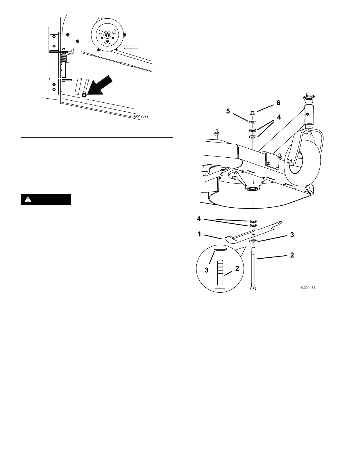
G012679
Figure16
SideDischargingorMulching theGrass
Thismowerhasahingedgrassdeectorthatdisperses
clippingstothesideanddowntowardtheturf.
adjustmentrange,in6mm(1/4inch)increments,ofcutting
heightinanyaxleposition.Usethesamenumberofblade
spacersonallbladestoachievealevelcut(2aboveand
2below ,1aboveand3below,etc.).
1.Disengagethebladecontrol(PTO)leverandsetthe
parkingbrakes.
2.Stoptheengineandwaitforallmovingpartstostop
beforeleavingtheoperatingposition.
3.Holdthebladeboltandremovethenut(Figure17).
DANGER
Withoutthegrassdeector,dischargecover,or
completegrasscatcherassemblymountedin
place,youandothersareexposedtobladecontact
andthrowndebris.Contactwithrotatingmower
blade(s)andthrowndebriswillcauseinjuryor
death.
•Neverremovethegrassdeectorfromthemower
becausethegrassdeectorroutesmaterialdown
towardtheturf.Ifthegrassdeectorisever
damaged,replaceitimmediately .
•Neverputyourhandsorfeetunderthemower.
•Nevertrytocleardischargeareaormower
bladesunlessyoureleasethebailandthepower
takeoff(PTO)isoff.Rotatetheignitionkeyto
Off.Alsoremovethekeyandpullthewiresoff
thesparkplug(s).
AdjustingtheHeightofCut
Thismachinehasa26to108mm(1to4-1/4inch)rangefor
theheightofcut.Thiscanbeachievedbyadjustingtheblade
spacers,rearaxleheight,andfrontcasterspacers.Usethe
Height-of-CutChart(page23)toselectthecombinationof
adjustmentsrequired.
Figure17
1.Blade
2.Bladebolt5.Thinwasher
3.Curvedwasher
4.Slidetheboltdownthroughthespindle,andchange
thespacersasneeded(Figure17).
5.Installtheboltandcurvedwasher,addextraspacer(s),
andsecurethemwithathinwasherandanut(Figure
17).
6.Torquethebladeboltto75-80ft-lb(101-108N-m).
4.Spacer
6.Nut
AdjustingtheBladeHeight
Adjustthebladesbyusingthe4spacers(6mm)(1/4inch),
onthebladespindlebolts.Thisallowsfora25mm(1-inch)
20
Page 21
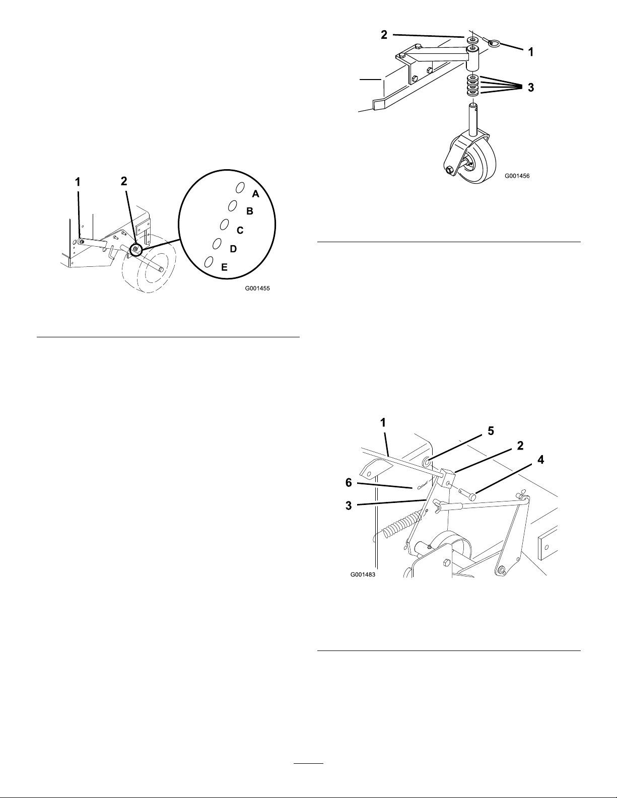
AdjustingtheAxleHeight
Adjusttheaxlepositiontotheselectedheight-of-cutsetting.
RefertotheHeight-of-CutChart.
1.Disengagethebladecontrol(PTO)leverandsetthe
parkingbrakes.
2.Stoptheengineandwaitforallmovingpartstostop
beforeleavingtheoperatingposition.
3.Loosen,butdonotremove,the2axlepivotboltsand
the2axleadjustmentbolts(Figure18).
Figure19
Figure18
1.Axlepivotbolt2.Axleadjustmentbolt
4.Placeajackundertherearcenteroftheengineframe.
Raisethebackendoftheengineframeupenoughto
removethefront2axleadjustmentbolts(Figure18).
Note:Usejackstandstosupportthemachine.
5.Raiseorlowertheengineframewiththejacksothat
youcaninstallthefront2axleadjustmentboltsinthe
desiredholelocation(Figure18).
Note:Useataperedpunchtohelpaligntheholes.
6.Tightenall4boltsandlowerthemower.
7.Adjustthecontrolrodsandthebrakelinkagesas
required.RefertoAdjustingtheControlRods(page
22)andServicingtheBrakes(page32).
1.Latchpin
2.Spacer,5mm(3/16inch)
3.Spacer,13mm(1/2inch)
2.Removethelatchpin,slidethecasterfromthesupport,
andchangethespacers(Figure19).
3.Installthecasterinthesupportandinsertthelatchpin
(Figure19).
AdjustingtheHandleHeight
Youcanadjustthehandlepositiontomatchyourheight
preference.
1.Removehairpincotter,washerandclevispinsecuring
controlrodttingtoidlerbracket(Figure20).
Important:Y oumustadjustthecontrolrods
andthebrakelinkagewhenyouchangetheaxle
positionsforpropertractionandbrakefunction.
AdjustingtheCasterPosition
1.UsingtheHeight-of-CutChart(page23),adjustthe
casterspacerstomatchwiththeaxleholeselected
(Figure19).
Figure20
1.Controlrod4.Clevispin
2.Controlrodtting
3.Idlerbracket6.Hairpincotter
5.Washer
2.Loosentheupperangebolts(3/8x1inch)andange
nutsecuringthehandletotherearframe(Figure21).
21
Page 22
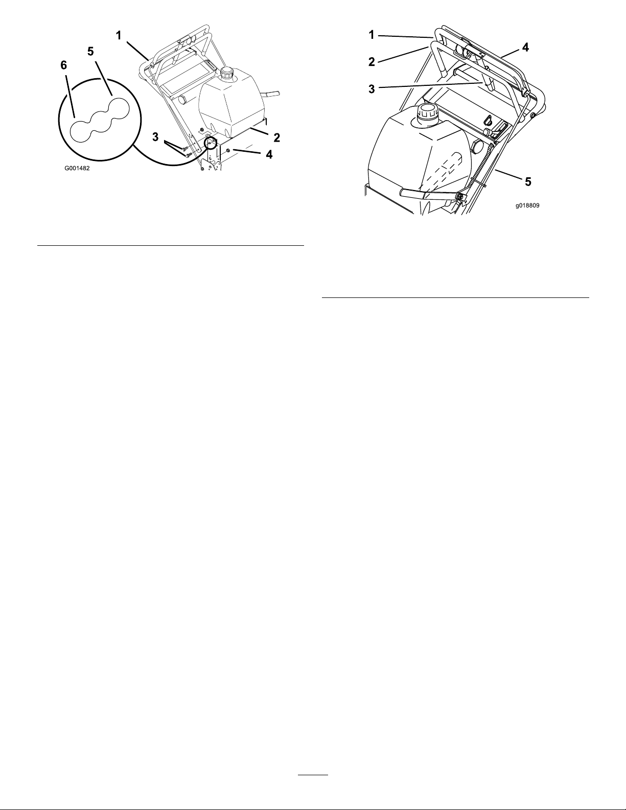
Figure21
g018809
1
2
3
4
5
1.Upperhandle
2.Rearframe
3.Flangebolt(3/8x1inch)
4.Locknut(3/8inch)
5.Uppermountinghole
6.Lowermountinghole
3.Removethelowerangebolts(3/8x1inch)andange
nutssecuringhandletorearframe(Figure21).
4.Pivothandletodesiredoperatingpositionandinstall
lowerangebolts(3/8x1inch)andangenutsinto
mountingholes.
Note:Tightenallangebolts.
5.Threadrodttingupordownonroduntilproper
positionisattainedandinstallintottingtoidler
bracketwithclevispin,washerandhairpincotter.
6.Checktheparkingbrakeadjustment.RefertoChecking
theBrakesinBrakeMaintenance(page32).
AdjustingtheControlRods
1.Checkthegapbetweentheuppercontrolbarandthe
xedbarwiththewheeldrivefullyengaged.Thegap
willneedtobeapproximately25to32mm(1to1-1/4
inches);refertoFigure22.
Figure22
1.25to32mm(1to1-1/4
inches)gap
2.Fixedcontrolbar
3.Parking-brakelever
4.Uppercontrolbar
5.Controlrod
Note:Theuppercontrolbarandthexedbarmust
beparallelintheengaged,relaxedandbrakepositions.
2.Checktheoperation.Ifadjustmentisrequired,remove
thehairpincotterpinsecuringtherodtotheupper
controlbar.Threadtherodinoroutofthecontrolrod
ttingforproperpositionandinstallthecontrolrod
intotheuppercontrolbarwiththehairpincotterpin.
3.Afteradjustingthecontrolrods,checktheparking
brakeadjustment;refertoServicingtheBrakeinBrake
Maintenance(page32).
22
Page 23

Height-of-CutChart
Numberofspacersbelow
Axle
position
A00
A01
A10
B01
B10
B11
B20
C
C
C
C
D21
D30
D31
D40
E31
E40
E41
thecaster
13mm
(1/2inch)
11
20
21
30
Numberof1/4inchbladespacersbelowthespindle
5mm
(3/16inch)
43210
26mm
(1inch)
29mm
(1-1/8inch)
35mm
(1-3/8inch)
35mm
(1-3/8inch)
41mm
(1-5/8inch)
45mm
(1-3/4inch)
51mm
(2inch)
48mm
(1-7/8inch)
55mm
(2-1/8inch)
57mm
(2-1/4inch)
64mm
(2-1/2inch)
61mm
(2-3/8inch)
64mm
(2-1/2inch)
70mm
(2-3/4inch)
76mm
(3inch)
73mm
(2-7/8inch)
79mm
(3-1/8inch)
82mm
(3-1/4inch)
32mm
(1-1/4inch)
35mm
(1-3/8inch)
41mm
(1-5/8inch)
41mm
(1-5/8inch)
48mm
(1-7/8inch)
51mm
(2inch)
57mm
(2-1/4inch)
54mm
(2-1/8inch)
60mm
(2-3/8inch)
64mm
(2-1/2inch)
70mm
(2-3/4inch)
67mm
(2-5/8inch)
70mm
(2-3/4inch)
76mm
(3inch)
82mm
(3-1/4inch)
79mm
(3-1/8inch)
86mm
(3-3/8inch)
89mm
(3-1/2inch)
38mm
(1-1/2inch)
41mm
(1-5/8inch)
48mm
(1-7/8inch)
48mm
(1-7/8inch)
54mm
(2-1/8inch)
57mm
(2-1/4inch)
64mm
(2-1/2inch)
60mm
(2-3/8inch)
67mm
(2-5/8inch)
70mm
(2-3/4inch)
76mm
(3inch)
73mm
(2-7/8inch)
76mm
(3inch)
82mm
(3-1/4inch)
89mm
(3-1/2inch)
86mm
(3-3/8inch)
92mm
(3-5/8inch)
95mm
(3-3/4inch)
45mm
(1-3/4inch)
48mm
(1-7/8inch)
54mm
(2-1/8inch)
54mm
(2-1/8inch)
60mm
(2-3/8inch)
64mm
(2-1/2inch)
70mm
(2-3/4inch)
67mm
(2-5/8inch)
73mm
(2-7/8inch)
76mm
(3inch)
83mm
(3-1/4inch)
79mm
(3-1/8inch)
82mm
(3-1/4inch)
89mm
(3-1/2inch)
95mm
(3-3/4inch)
92mm
(3-5/8inch)
98mm
(3-7/8inch)
102mm
(4inch)
51mm
(2inch)
54mm
(2-1/8inch)
60mm
(2-3/8inch)
60mm
(2-3/8inch)
67mm
(2-5/8inch)
70mm
(2-3/4inch)
76mm
(3inch)
73mm
(2-7/8inch)
79mm
(3-1/8inch)
83mm
(3-1/4inch)
89mm
(3-1/2inch)
86mm
(3-3/8inch)
89mm
(3-1/2inch)
95mm
(3-3/4inch)
102mm
(4inch)
98mm
(3-7/8inch)
105mm
(4-1/8inch)
108mm
(4-1/4inch)
23
Page 24

Maintenance
Note:Determinetheleftandrightsidesofthemachinefromthenormaloperatingposition.
RecommendedMaintenanceSchedule(s)
MaintenanceService
Interval
Aftertherst8hours
Beforeeachuseordaily
Every25hours
Every50hours
Every100hours
Every200hours
MaintenanceProcedure
•Changetheengineoil.
•Checkthesafetysystem.
•Greasethecasterwheelsandcasterpivot.
•Checktheengine-oillevel.
•Cleantheair-intakescreen.
•Cleantheairintakescreenfromgrassanddebrisbeforeeachuse.
•Checkthebrakes.
•Inspecttheblades.
•Cleanthemowerdeck.
•Cleanthefoamair-cleanerelement.
•Greasethemower-beltidler.
•Checkthepaperair-cleanerelement.
•Checkthetirepressure.
•Checkthebelts.
•Changetheengineoil.
•Checkthesparkplugs.
•Checkandcleantheengine-coolingnsandshrouds.
•Replacethepaperair-cleanerelement.
•Changetheoillter.
•Replacethefuellter.
•Replacethefuel-ventlter.
Every250hours
Every400hours
Beforestorage
•Greasethetransmissioncouplers(moreoftenindirtyordustyconditions).
•Greasethewheelbearings(moreoftenindirtyordustyconditions).
•Paintchippedsurfaces.
•Performallmaintenanceprocedureslistedabovebeforestorage.
Important:Refertoyourengineowner'smanualforadditionalmaintenanceprocedures.
CAUTION
Ifyouleavethekeyintheignitionswitch,someonecouldaccidentlystarttheengineandseriouslyinjure
youorotherbystanders.
Removethekeyfromtheignitionanddisconnectthespark-plugwire(s)fromthesparkplug(s)beforeyou
doanymaintenance.Setthewireasidesothatitdoesnotaccidentallycontactthesparkplug.
24
Page 25
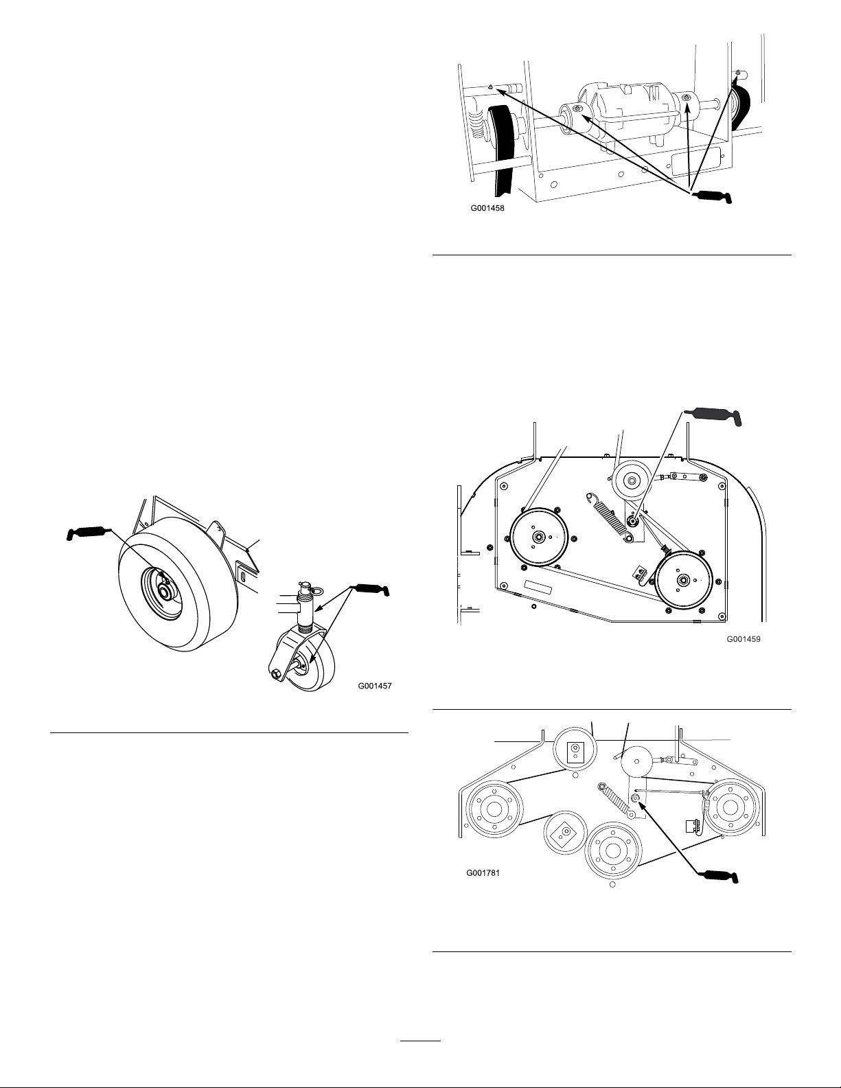
Lubrication
GreaseType:#2general-purposelithium-basedor
molybdenum-basedgrease
LubricatingtheMachine
1.DisengagethePTOandsettheparkingbrake.
2.Stoptheengine,removethekey,andwaitforallmoving
partstostopbeforeleavingtheoperatingposition.
3.Cleanthegreasettingswitharag.Makesuretoscrape
anypaintoffthefrontofthetting(s).
4.Connectagreaseguntothetting.Pumpgrease
intothettingsuntilgreasebeginstooozeoutofthe
bearings.
5.Wipeupanyexcessgrease.
Figure24
GreasingtheMowerBeltIdler
Greasethettingonthemowerbelt-idlerarmpivot(Figure
25).
LubricatingtheCasterand WheelBearings
1.Lubricatethefront-wheelbearingsandfrontspindles
(Figure23).
2.Lubricatethedrive-wheelbearings(Figure23).
Figure23
Note:Removethemower-deckcovertoaccessthegrease
ttingforthemowerbelt-idlerarm.
Figure25
32-inchand36-inchmowerdeck
GreasingtheTransmission Couplers
Lubricatethetransmissioncouplersandidlerarmpivots
locatedinthebackofthemachine(Figure24).
Figure26
48-inchmowerdeck
25
Page 26
EngineMaintenance
ServicingtheAirCleaner
2.Drytheelementbysqueezingitinacleancloth.
Important:Replacethefoamelementifitistorn
orworn.
ServiceInterval:Every25hours—Cleanthefoam
air-cleanerelement.
Every50hours—Checkthepaperair-cleanerelement.
Every200hours—Replacethepaperair-cleaner
element.
Note:Servicetheaircleanermorefrequently(everyfew
operatinghours)iftheoperatingconditionsareextremely
dustyorsandy .
Important:Donotoilthefoamorpaperelement.
RemovingtheFoamandPaper
Elements
1.DisengagethePTOandsettheparkingbrake.
2.Stoptheengine,removethekey,andwaitforallmoving
partstostopbeforeleavingtheoperatingposition.
3.Cleanaroundtheaircleanertopreventdirtfrom
gettingintotheengineandcausingdamage(Figure27).
4.Unscrewthecoverknobsandremovetheair-cleaner
cover(Figure27).
5.Unscrewthehoseclampandremovetheaircleaner
assembly(Figure27).
6.Carefullypullthefoamelementoffthepaperelement
(Figure27).
ServicingthePaperAir-Cleaner
Element
1.Donotcleanthepaperlter,replaceit(Figure27).
2.Inspecttheelementfortears,anoilylm,ordamageto
therubberseal.
3.Replacethepaperelementifitisdamaged.
InstallingtheFoamandPaperElements
Important:Topreventenginedamage,alwaysoperate
theenginewiththecompletefoamandpaperaircleaner
assemblyinstalled.
1.Carefullyslidethefoamelementontothepaper
air-cleanerelement(Figure27).
2.Placetheaircleanerassemblyontotheaircleanerbase
andsecureitwiththe2wingnuts(Figure27).
3.Placetheair-cleanercoverintopositionandtighten
thecoverknob(Figure27).
ServicingtheEngineOil
ServiceInterval:Beforeeachuseordaily—Checkthe
engine-oillevel.
Aftertherst8hours—Changetheengineoil.
Every100hours—Changetheengineoil.
Every200hours—Changetheoillter.
Figure27
1.Cover
2.Hoseclamp4.Foamelement
3.Paperelement
CleaningtheFoamAir-CleanerElement
1.Washthefoamelementinliquidsoapandwarmwater.
Whentheelementisclean,rinseitthoroughly .
Note:Changetheoilmorefrequentlywhentheoperating
conditionsareextremelydustyorsandy.
OilType:Detergentoil(APIserviceSF,SG,SH,SJorSL)
CrankcaseCapacity:1.7L(1.8USqt)withthelter
removed;1.5L(1.6USqt)withoutthelterremoved
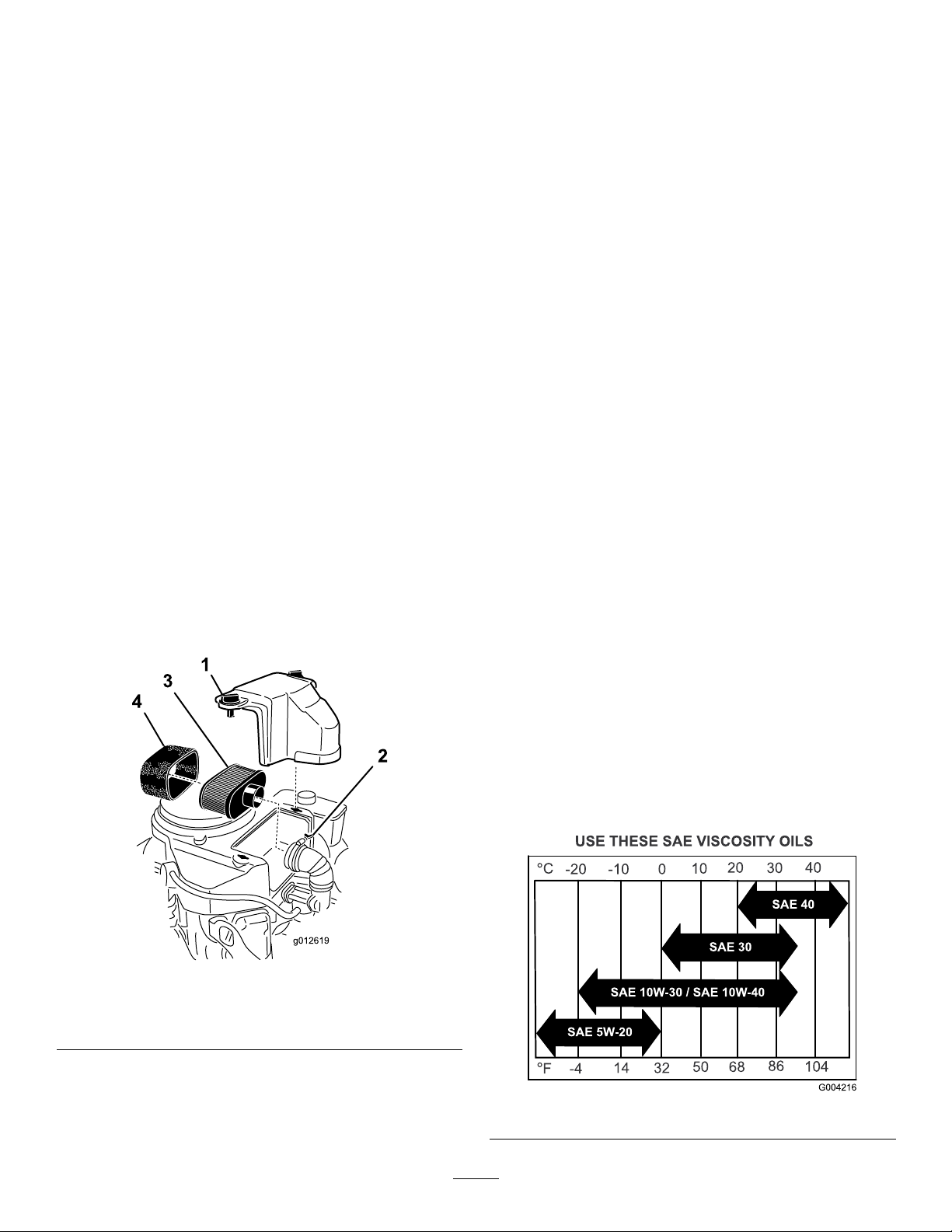
Viscosity:Refertothetable(Figure28).
Figure28
26
Page 27
CheckingtheEngine-OilLevel
ChangingtheEngineOil
1.Parkthemachineonalevelsurface.
2.DisengagethePTOandsettheparkingbrake.
3.Stoptheengine,removethekey,andwaitforallmoving
partstostopbeforeleavingtheoperatingposition.
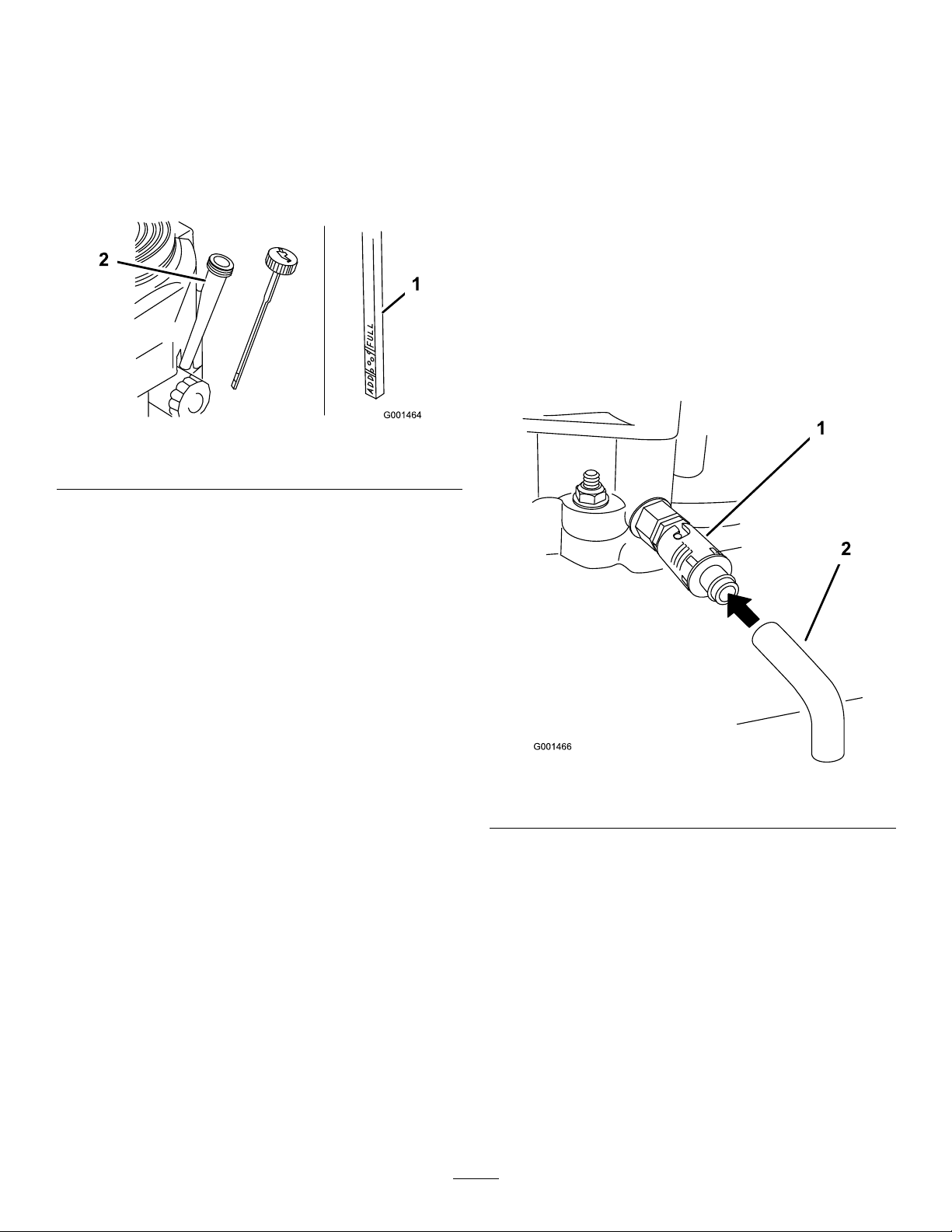
4.Cleanaroundtheoildipstick(Figure29)sothatdirt
cannotfallintothellerholeanddamagetheengine.
Figure29
1.Oildipstick
5.Unscrewtheoildipstickandwipetheendclean(Figure
29).
2.Fillertube
1.Parkthemachinesothatthedrainsideisslightlylower
thantheoppositesidetoensurethattheoildrains
completely.
2.DisengagethePTOandsettheparkingbrake.
3.Stoptheengine,removethekey,andwaitforallmoving
partstostopbeforeleavingtheoperatingposition.
4.Slidethedrainhoseovertheoildrainvalve.
5.Placeapanbelowthedrainhose.
Note:Rotateoildrainvalvetoallowoiltodrain
(Figure30).
6.Whenoilhasdrainedcompletely,closethedrainvalve.
7.Removethedrainhose(Figure30).
Note:Disposeoftheusedoilatarecyclingcenter.
6.Slidetheoildipstickfullyintothellertube,butdonot
threaditontothetube(Figure29).
7.Pullthedipstickoutandlookattheend.Iftheoillevel
islow,slowlypouronlyenoughoilintothellertube
toraisetheleveltotheFullmark.
Important:Donotoverllthecrankcasewithoil
andruntheengine;enginedamagecanresult.
Figure30
1.Oildrainvalve2.Oildrainhose
8.Slowlypourapproximately80%ofthespeciedoil
intothellertube(Figure29).
9.Checktheoillevel;refertoCheckingtheEngine-Oil
Level(page27).
10.SlowlyaddtheadditionaloiltobringittotheFull
mark.
ChangingtheOilFilter
Note:Changetheoilltermorefrequentlywhenthe
operatingconditionsareextremelydustyorsandy.
1.Draintheoilfromtheengine;refertoChangingthe
EngineOil(page27).
2.Removetheoldlter(Figure31).
27
Page 28
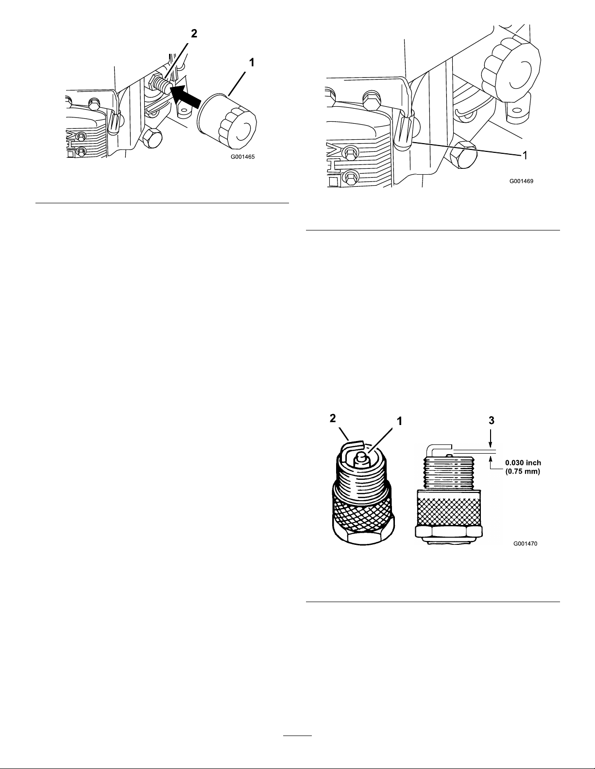
Figure31
1
1.Oillter
2.Adapter
3.Applyathincoatofnewoiltotherubbergasketon
thereplacementlter(Figure31).
4.Installthereplacementoilltertothelteradapter,
turntheoillterclockwiseuntiltherubbergasket
contactsthelteradapter,thentightenthelteran
additional3/4turn(Figure31).
5.Fillthecrankcasewiththepropertypeofnewoil;refer
toServicingtheEngineOil(page26).
6.Runtheengineforabout3minutes,stoptheengine,
andcheckforoilleaksaroundtheoillteranddrain
valve.
7.Checktheengineoillevelandaddoilifneeded.
8.Wipeupanyspilledoil.
ServicingtheSparkPlugs
ServiceInterval:Every100hours—Checkthesparkplugs.
Ensurethattheairgapbetweenthecenterelectrodeandthe
sideelectrodeiscorrectbeforeinstallingeachsparkplug.Use
aspark-plugwrenchforremovingandinstallingthespark
plugsandagappingtoolorafeelergaugetocheckandadjust
theairgap.Installnewsparkplugsifnecessary.
Figure32
1.Spark-plugwire/sparkplug
4.Cleanaroundthesparkplugstopreventdirtfrom
fallingintotheengineandpotentiallycausingdamage.
5.Removethesparkplugsandthemetalwashers.
CheckingtheSparkPlugs
1.Lookatthecenterofthesparkplugs(Figure33).
Note:Ifyouseelightbrownorgrayontheinsulator,
theengineisoperatingproperly .Ablackcoatingonthe
insulatorusuallymeansthattheaircleanerisdirty.
2.Ifneeded,cleanthesparkplugwithawirebrushto
removecarbondeposits.
Type:Champion®RCJ8Yorequivalent
AirGap:0.75mm(0.030inch)
RemovingtheSparkPlugs
1.DisengagethePTOandsettheparkingbrake.
2.Stoptheengine,removethekey,andwaitforallmoving
partstostopbeforeleavingtheoperatingposition.
3.Disconnectthewiresfromthesparkplugs(Figure32).
Figure33
1.Centerelectrode;insulator3.Airgap(nottoscale)
2.Sideelectrode
Important:Alwaysreplacethesparkplugswhen
theyhavewornelectrodes,anoilylm,ora
crackedinsulator.
3.Checkthegapbetweenthecenterelectrodeandthe
sideelectrode(Figure33).
Note:Bendthesideelectrode(Figure33)ifthegapis
notcorrect.
28
Page 29
InstallingtheSparkPlugs
1.Installthesparkplugsandthemetalwasher.Ensure
thattheairgapissetcorrectly.
2.Tightenthesparkplugsto22N-m(16ft-lb).
3.Connectthewirestothesparkplugs(Figure33).
FuelSystem
Maintenance
ServicingtheFuelSystem
DANGER
Incertainconditions,gasolineisextremely
ammableandhighlyexplosive.Areorexplosion
fromgasolinecanburnyouandothersandcan
damageproperty.
•Draingasolinefromthefueltankwhenthe
engineiscold.Dothisoutdoorsinanopenarea.
Wipeupanygasolinethatspills.
•Neversmokewhendraininggasoline,andstay
awayfromanopenameorwhereasparkmay
ignitethegasolinefumes.
DrainingtheFuelTank
1.Parkthemachineonalevelsurfacetoensurethatthe
fueltankdrainscompletely;thendisengagethepower
take-off(PTO),settheparkingbrake,andturnthe
ignitionkeytotheOffposition.Removethekey .
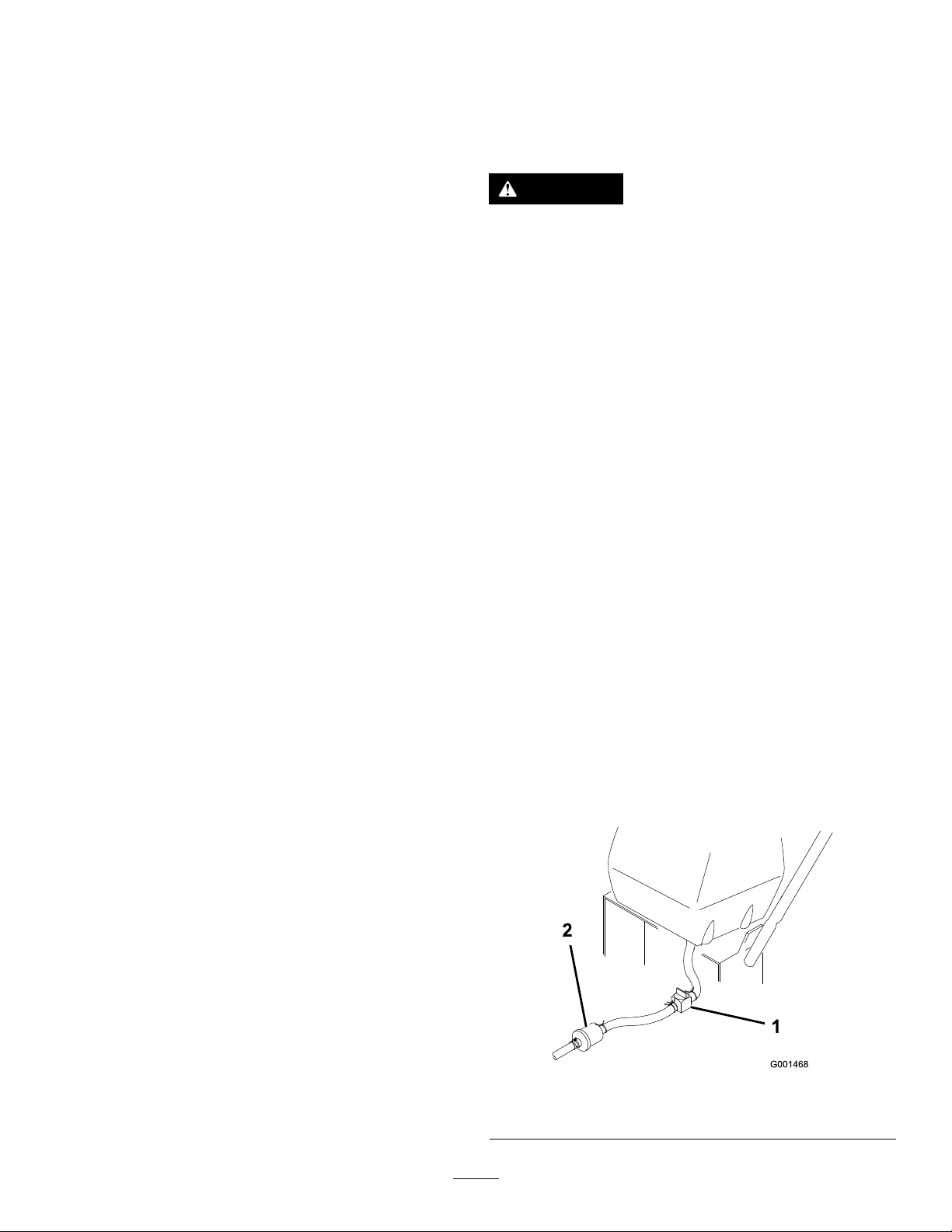
2.Closethefuel-shutoffvalveatthefueltank(Figure34).
3.Squeezetheendsofthehoseclamptogetherandslide
itupthefuellineawayfromfuellter(Figure34).
4.Pullthefuellineoffthefuellter(Figure34).
5.Openthefuel-shutoffvalveandallowthegasolineto
drainintoagascanordrainpan.
Note:Nowisthebesttimetoinstallanewfuellter
becausethefueltankisempty.RefertoReplacingthe
FuelFilter(page30).
6.Installthefuellineontothefuellter.Slidethehose
clampclosetothevalvetosecurethefuelline.
1.Fuel-shutoffvalve2.Clamp
29
Figure34
Page 30
ReplacingtheFuelFilter
g014686
1 2
ServiceInterval:Every200hours/Yearly(whichevercomes
rst)
Neverinstalladirtylterifitisremovedfromthefuelline.
Note:Notehowthefuellterisinstalledinordertoinstall
thenewltercorrectly.
Note:Wipeupanyspilledfuel.
1.DisengagethePTOandsettheparkingbrake.
2.Stoptheengine,removethekey,andwaitforallmoving
partstostopbeforeleavingtheoperatingposition.
3.Closethefuel-shutoffvalveatthefueltank(Figure34).
4.Squeezetheendsofthehoseclampstogetherandslide
themawayfromthelter(Figure35).
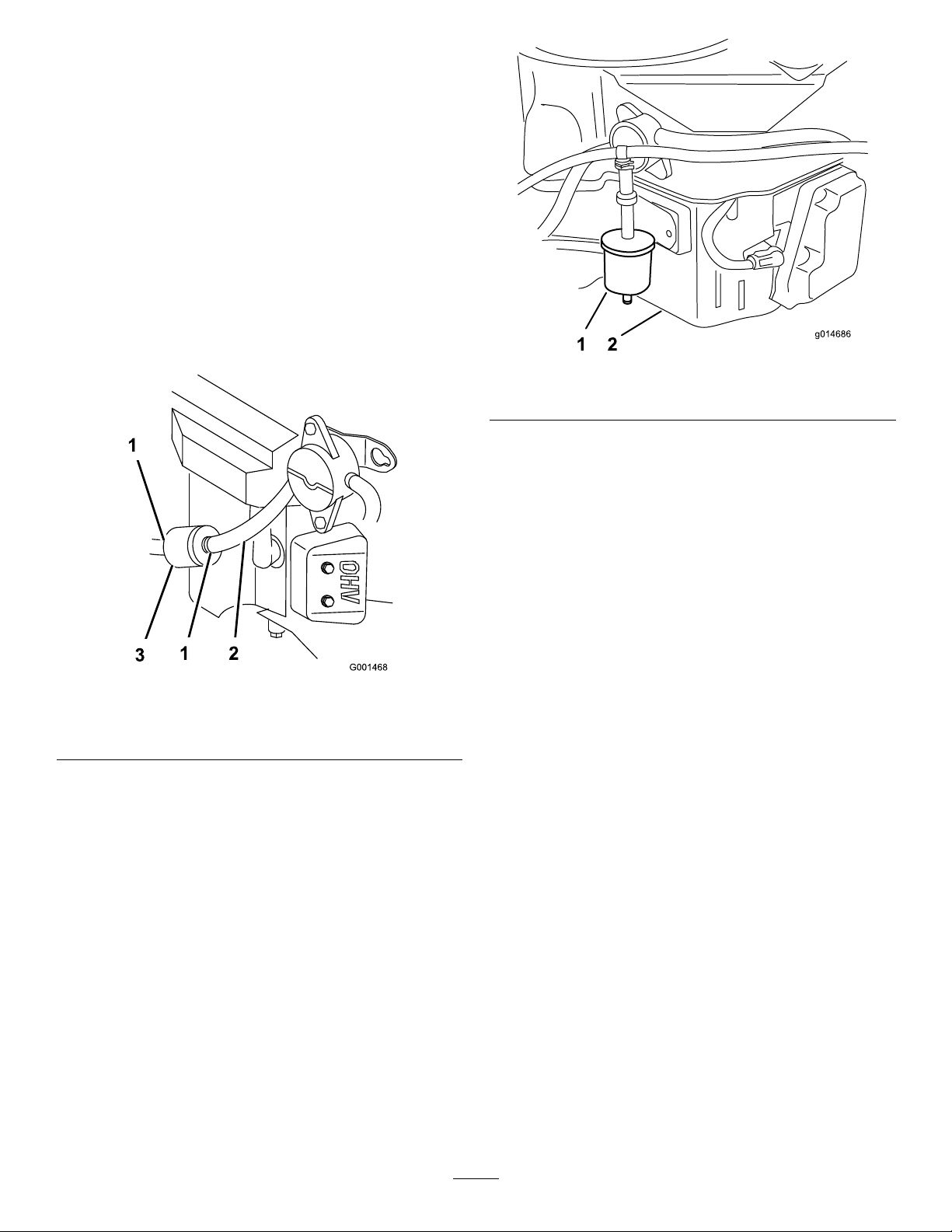
Figure36
1.Fuel-ventlter2.Rightsideofengine
Figure35
1.Hoseclamp3.Filter
2.Fuelline
5.Removethelterfromthefuellines.
6.Installanewlterandmovethehoseclampscloseto
thelter.
7.Openthefuel-shutoffvalveatthefueltank(Figure34).
8.Checkforfuelleaks,andrepairifneeded.
9.Wipeupanyfuelthatspilled.
ServicingtheFuel-VentSystem
ServiceInterval:Every200hours/Yearly(whichevercomes
rst)
1.DisengagethePTOandsettheparkingbrake.
2.Stoptheengine,removethekey,andwaitforallmoving
partstostopbeforeleavingtheoperatingposition.
3.Removetheexistingfuel-ventlter(Figure36).
4.Installanewlter.
30
Page 31
DriveSystem
CoolingSystem
Maintenance
CheckingtheTirePressure
ServiceInterval:Every50hours/Monthly(whichever
comesrst)
Maintaintheairpressureinthereartiresat83to97kPa(12
to14psi).Uneventirepressurecancauseanunevencut.
Note:Thefronttiresaresemi-pneumatictiresanddonot
requireairpressuremaintenance.
Maintenance
CleaningtheAir-IntakeScreen
Beforeeachuse,removeanybuildupofgrass,dirt,or
otherdebrisfromthecylinderandcylinder-headcooling
ns,theair-intakescreenontheywheelend,andthe
carburetor-governorleversandlinkage.Thiswillhelpensure
adequatecoolingandcorrectenginespeedandwillreduce
thepossibilityofoverheatingandmechanicaldamagetothe
engine.
CleaningtheCoolingSystem
ServiceInterval:Beforeeachuseordaily
Every100hours/Yearly(whichevercomesrst)
1.DisengagethePTOandsettheparkingbrake.
2.Stoptheengine,removethekey,andwaitforallmoving
partstostopbeforeleavingtheoperatingposition.
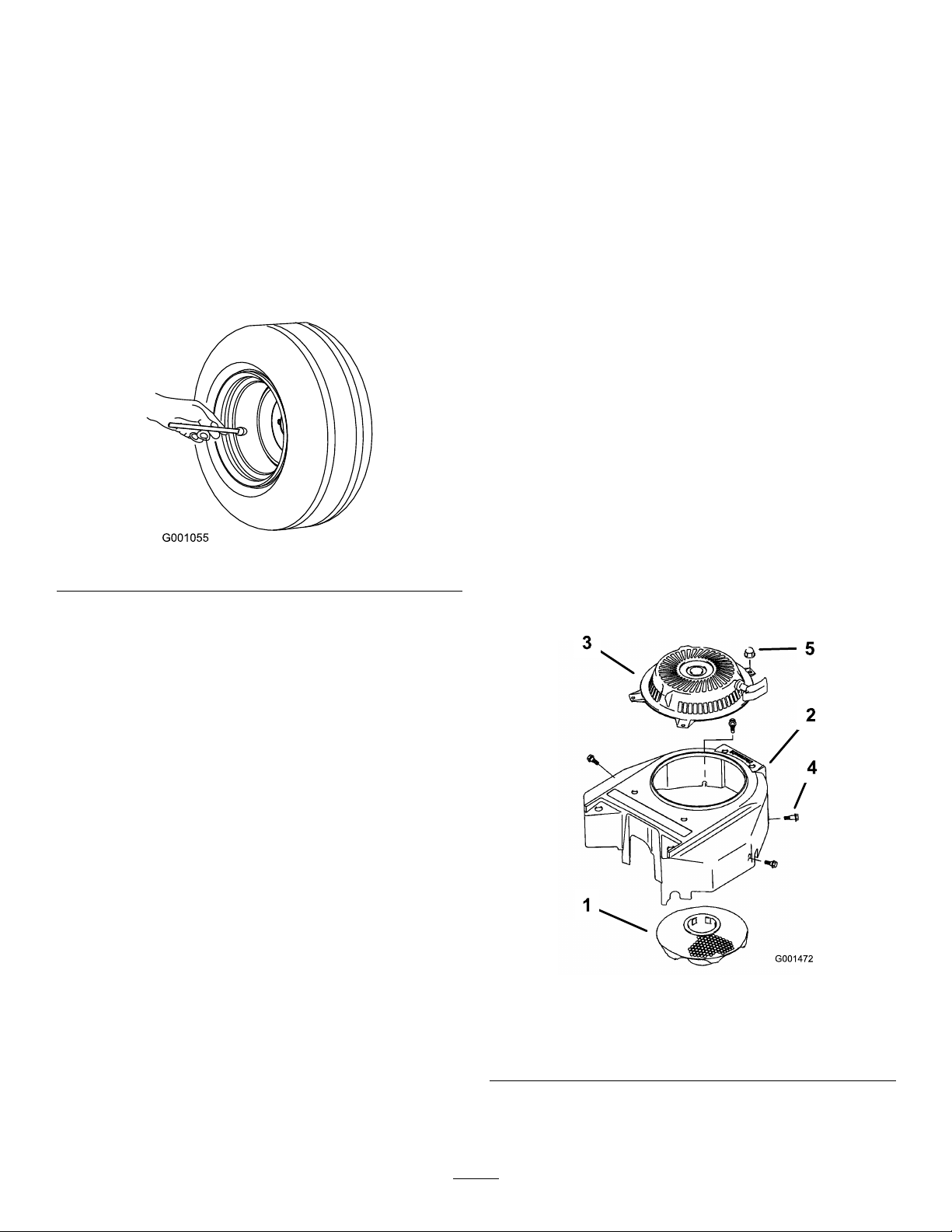
3.Removetheair-intakescreen,therecoilstarter,and
thefanhousing(Figure38).
Figure37
4.Cleanthedebrisandgrassfromtheengineparts.
5.Installtheair-intakescreen,therecoilstarter,andthe
fanhousing(Figure38).
Figure38
1.Air-intakescreen4.Bolt
2.Fanhousing5.Nut
3.Recoilstarter
31
Page 32
BrakeMaintenance
ServicingtheBrakes
3.Checkthebrakebeforeyouadjustit;refertoChecking
theBrakes(page32).
4.Releasetheparkingbrake;refertoReleasingthe
ParkingBrake(page15).
Beforeeachuse,checkbrakesonbothalevelsurfaceand
slope.
Alwayssettheparkingbrakewhenyoustopthemachine
orleaveitunattended.Iftheparkingbrakedoesnothold
securely,adjustit.
CheckingtheBrakes
1.Parkthemachineonalevelsurface,disengagethe
bladecontrol(PTO).
2.Stoptheengine,removethekey,andwaitforallmoving
partstostopbeforeleavingtheoperatingposition.
3.Applytheparkingbrake.
Note:Thewheelsmustlockwhenyoutrytopush
themachineforward.
4.Ifthewheelsdonotlock,adjustthebrakes.Referto
AdjustingtheBrakes(page32).
5.Releasethebrakeandpressuppercontrolbarvery
lightly,approximately13mm(1/2inch).
Note:Thewheelsshouldrotatefreely;ifnot,referto
AdjustingtheBrakes(page32).
AdjustingtheBrakes
Thebrakeleverisontheuppercontrolbar.Iftheparking
brakedoesnotholdsecurely,anadjustmentisrequired.
1.Parkthemachineonalevelsurface,disengagethe
PTO,andsettheparkingbrake.
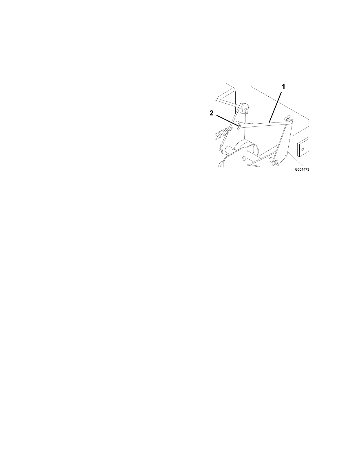
5.Toadjustthebrake,rotatethewingnutsonthebrake
rods(Figure39).Turnthewingnutsclockwiseto
tightenthebrakeandcounterclockwisetoloosenthe
brake.
Figure39
1.Brakerod2.Wingnut
Note:Controlbarshouldbeparallelwiththe
referencebarwhenproperlyadjusted.
6.Checkthebrakeoperationagain;refertoCheckingthe
Brakes(page32).
Important:Withtheparkingbrakereleased,the
rearwheelsmustrotatefreelywhenyoupushthe
mower.Ifbrakeactionandfreewheelrotation
cannotbeachievedcontactyourservicedealer
immediately.
2.Stoptheengine,removethekey,andwaitforallmoving
partstostopbeforeleavingtheoperatingposition.
32
Page 33
BeltMaintenance
CheckingtheBelts
ServiceInterval:Every50hours/Monthly(whichever
comesrst)—Checkthebelts.
Checkthebeltsforcracks,frayededges,burnmarks,wear,
signsofoverheating,oranyotherdamage.Replaceany
damagedbelts.
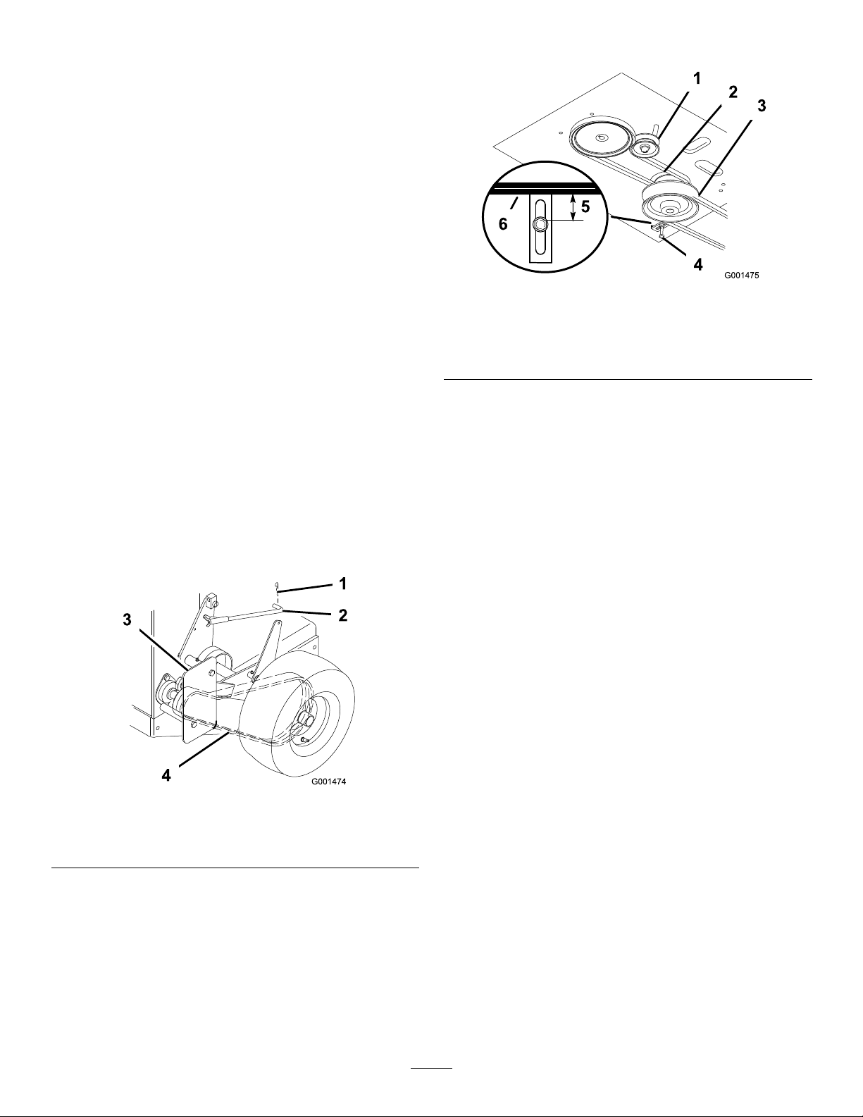
ReplacingtheTractionDrive Belt
1.Removethehairpincottersecuringthebrakerodto
thebrakearmtorelaxthetensiononthebeltidler
(Figure40).
2.Removethebottomboltandloosenthetopboltofthe
shieldtorotateitforbeltclearance(Figure40).
3.Liftthebeltpasttheidlerandoffthedrivepulley
(Figure40).
4.Raisethewheeloffthegroundenoughtoremovethe
belt.
5.Replacethetraction-drivebelt.
6.Securetheshieldwiththepreviouslyremovedboltand
tightenthebolts(Figure40).
7.Securethebrakerodtothebrakearmwiththehairpin
cotter(Figure40).
4.Removethemowerbelt(Figure41).
Figure41
1.Idlerpulleyinslot4.Beltguide
2.Tractionbelt
3.Mowerbelt6.Mowerbelt
5.Loosenthepivotboltenoughtoslidetheidlerpulleyin
theslot,andremovethetractionbeltfromtheengine
andthedrivepulleys(Figure41).
6.Installthenewdrivebeltaroundtheengineandthe
drivepulleys(Figure41).
7.Slidetheidlerpulleyintheengineframetotensionthe
tractionbelt(Figure41).
8.Installthemowerbelt(Figure41).
9.Checkthebeltguideundertheengineframeforthe
properadjustment(Figure41).
5.19mm(3/4inch)
Figure40
1.Hairpincotter
2.Brakerod4.Drivebelt
3.Shield
ReplacingtheDriveBelt
1.Disengagetheblade-control(PTO)leverandsetthe
parkingbrakes.
2.Stoptheengineandwaitforallmovingpartstostop
beforeleavingtheoperatingposition.
3.Raisetherearofthemachineandholditupwithjack
stands.
Note:Thedistancebetweenthebeltguideandmower
beltshouldbe19mm(3/4inch)whenyouengage
themowerbelt.Adjustthebeltifnecessary.The
disengagedbeltshouldnotdragorfalloffthepulley
whentheguidesareproperlyadjusted.
ReplacingtheMowerBelt
Important:Thebrakeneedstobeadjustedwhenthe
belttensionorthebrakelinkageisadjusted.
1.Disengagetheblade-control(PTO)leverandsetthe
parkingbrakes.
2.Stoptheengineandwaitforallmovingpartstostop
beforeleavingtheoperatingposition.
3.Removetheknobsandthebeltcoveronthemower.
4.Removetheidlerpulleyandthewornbelt.
5.Installthenewmowerbelt.
6.Installtheidlerpulley.
7.Engagetheblade-control(PTO)leverandcheck
thebelttension.RefertoAdjustingtheMowerBelt
Tension(page34).
33
Page 34
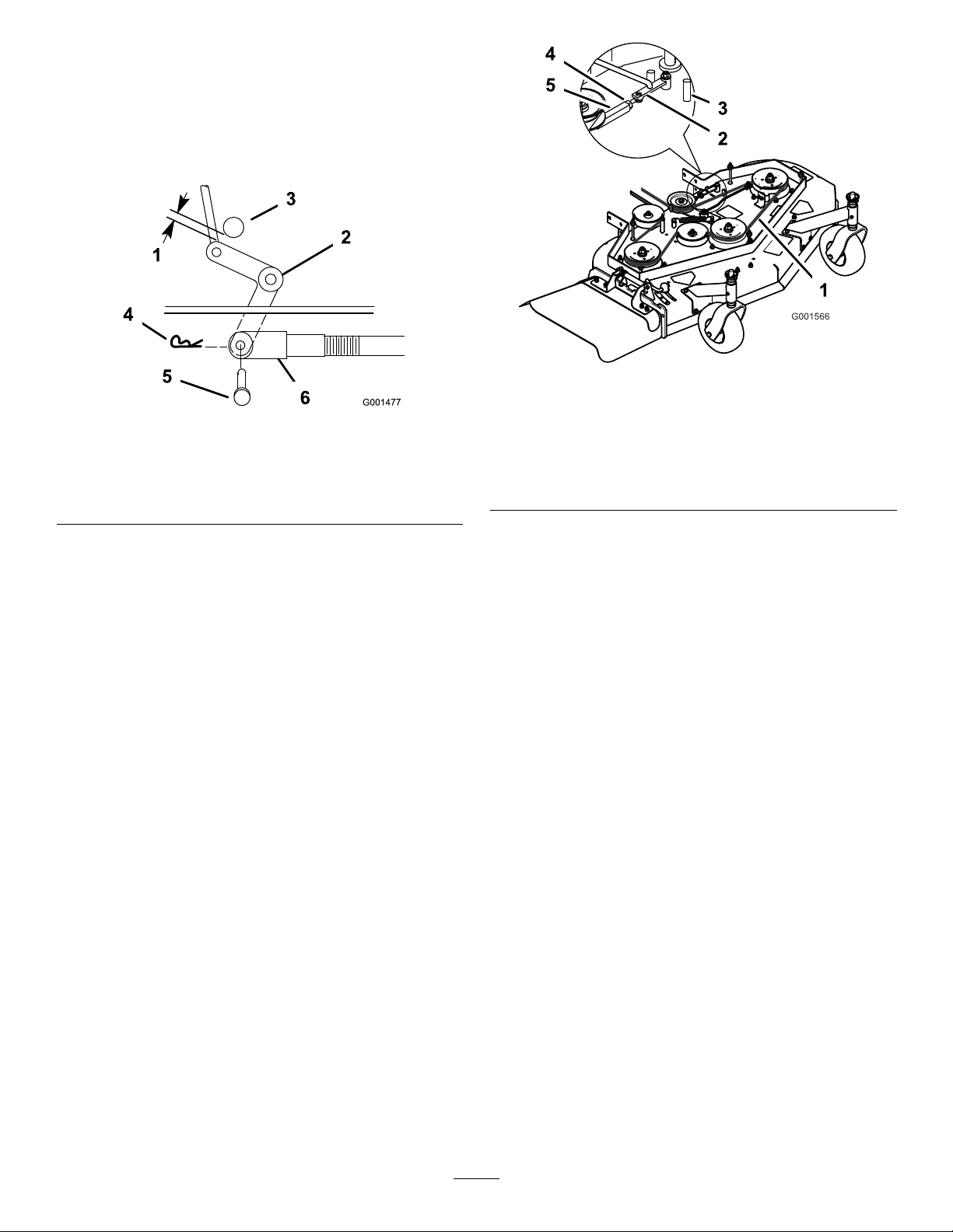
Note:Thepropermowerbelttensionis44to67N-m
(10to15ft-lb)withthebeltdeected13mm(1/2inch)
halfwaybetweenthepulleys(Figure44).
8.Engagetheblade-control(PTO)lever.
9.Checktheclearancebetweenthebellcrankandthe
transmissionoutputshaft(Figure42).
Figure43
48-inchmowerdeck
Figure42
1.2to3mm(1/16to1/8inch)
2.Bellcrank
3.Transmissionoutputshaft6.Clevis
4.Hairpincotter
5.Clevispin
Note:Theclearanceshouldbe2to3mm(1/16to
1/8inch).
10.Removethehairpincotterpinandtheclevispinfrom
thebellcrank.
11.Rotatetheclevisclockwiseontherodtoincreasethe
clearance;rotateitcounterclockwisetodecreaseit
(Figure42).
12.Disengagetheblade-control(PTO)lever.
Note:Iftheassistarmdoesnotcontactthefrontstop
onthemowerdeck(Figure43),adjusttheclevisto
bringthebellcrankclosertothetransmissionoutput
shaft(Figure42).
1.13mm(1/2inch)deection
here
2.Assistarm5.Turnbuckle
3.Frontstop
4.Locknut
13.Checkthebeltguideundertheengineframeforthe
properadjustment(Figure41).
Note:Thedistancebetweenthebeltguideandthe
mowerbeltshouldbe32mm(1-1/4inch)whenyou
engagethemowerbelt.Adjustthemowerbeltas
necessary.Thedisengagedbeltshouldnotdragorfall
offthepulleywhentheguidesareproperlyadjusted.
AdjustingtheMowerBelt Tension
Important:Adjustthebrakewhenyouadjustthebelt
tensionorthebrakelinkage.
Important:Thebeltmustbetightenoughtonotslip
duringheavyloadswhilecuttinggrass.Over-tensioning
thebeltwillreducethelifeofthespindlebearing,the
belt,andtheidlerpulley .
1.Disengagetheblade-control(PTO)leverandsetthe
parkingbrakes.
2.Stoptheengineandwaitforallmovingpartstostop
beforeleavingtheoperatingposition.
3.Loosenthelocknutontheturnbuckle(Figure45).
4.Rotatetheturnbuckletowardtherearofthemowerto
increasethetensiononthebelt.Rotatetheturnbuckle
towardthefrontofthemowertodecreasethetension
onthebelt(Figure45).
Note:Thepropermowerbelttensionis44to67N-m
(10to15ft-lb)withthebeltdeected13mm(1/2inch)
halfwaybetweenthepulleys(Figure44).
34
Page 35
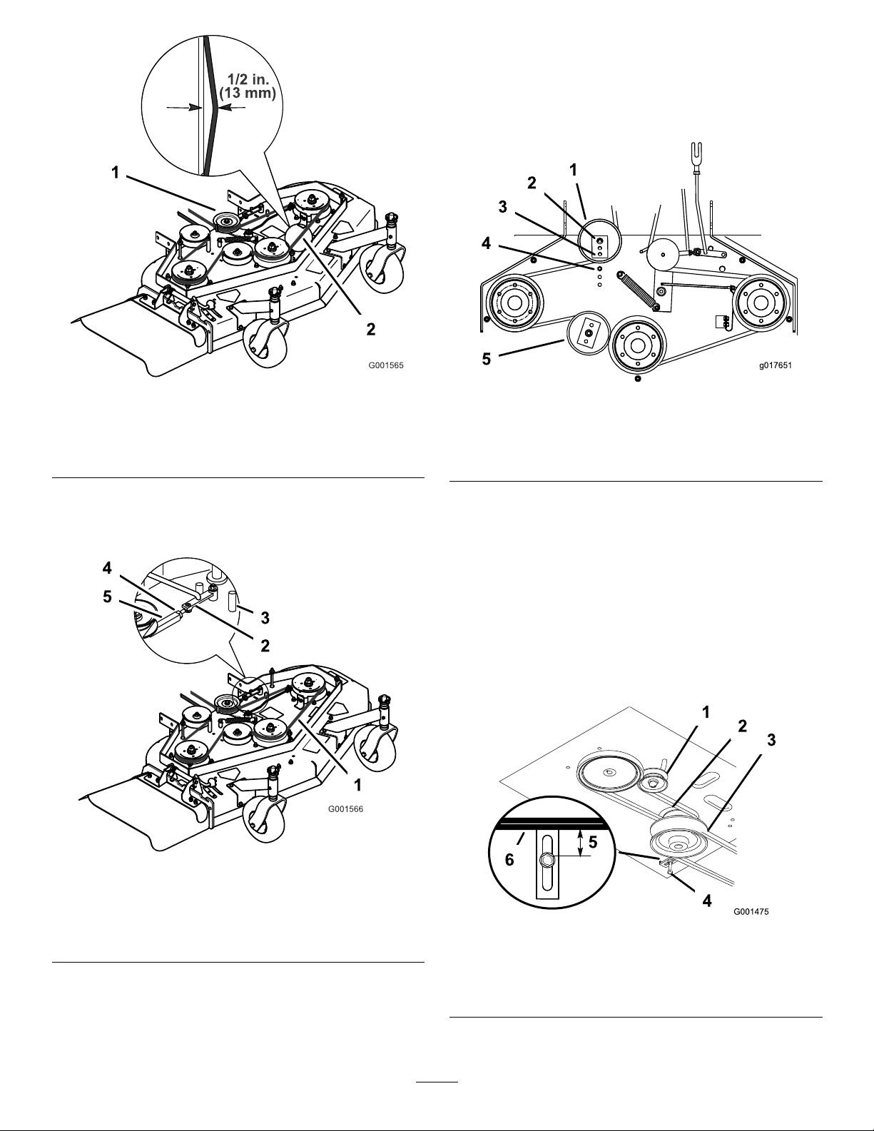
positionedtothemiddleorfronthole(Figure46).Use
g017651
theholethatwillgivethecorrectadjustment.
7.Whenyoumovetheidlerpulley,youmustmovethe
beltguide.Movethebeltguidetothefrontposition
(Figure46).
Figure44
48-inchmowerdeck
1.Idlerpulley2.Mowerbeltwith13mm
(1/2inch)deection
Note:Theeyeboltthreadsonbothendsofthe
turnbuckleshouldbeengagedaminimumof8mm
(5/16inch).
Figure46
1.Rearidlerpulley4.Beltguideinbackposition
2.Middlehole5.Frontidlerpulley
3.Fronthole
8.Checkthebeltguideundertheengineframeforproper
adjustment(Figure47).
Note:Thedistancebetweenthebeltguideandthe
mowerbeltshouldbe19mm(3/4inch)whenyou
engagethemowerbelt(Figure47).Adjustthemower
beltasnecessary.Thedisengagedbeltshouldnotdrag
orfalloffthepulleywhentheguidesandbelttension
areproperlyadjusted.
9.Checktheblade-brakeadjustment;refertoAdjusting
theBladeBrake(page40).
Figure45
1.13mm(1/2inch)deection
here
2.Assistarm5.Turnbuckle
3.Frontstop
4.Locknut
5.Engagetheblade-controllever(PTO)andcheckthe
belttension.
6.Ifthereisnoadjustmentleftintheturnbuckleand
thebeltisstillloose,therearidlerpulleyneedstobe
Figure47
1.Idlerpulleyinslot4.Beltguide
2.Tractionbelt
3.Mowerbelt6.Mowerbelt
35
5.19mm(3/4inch)
Page 36
AdjustingthePTO
g017648
1
2
3
4
g017649
EngagementLinkage
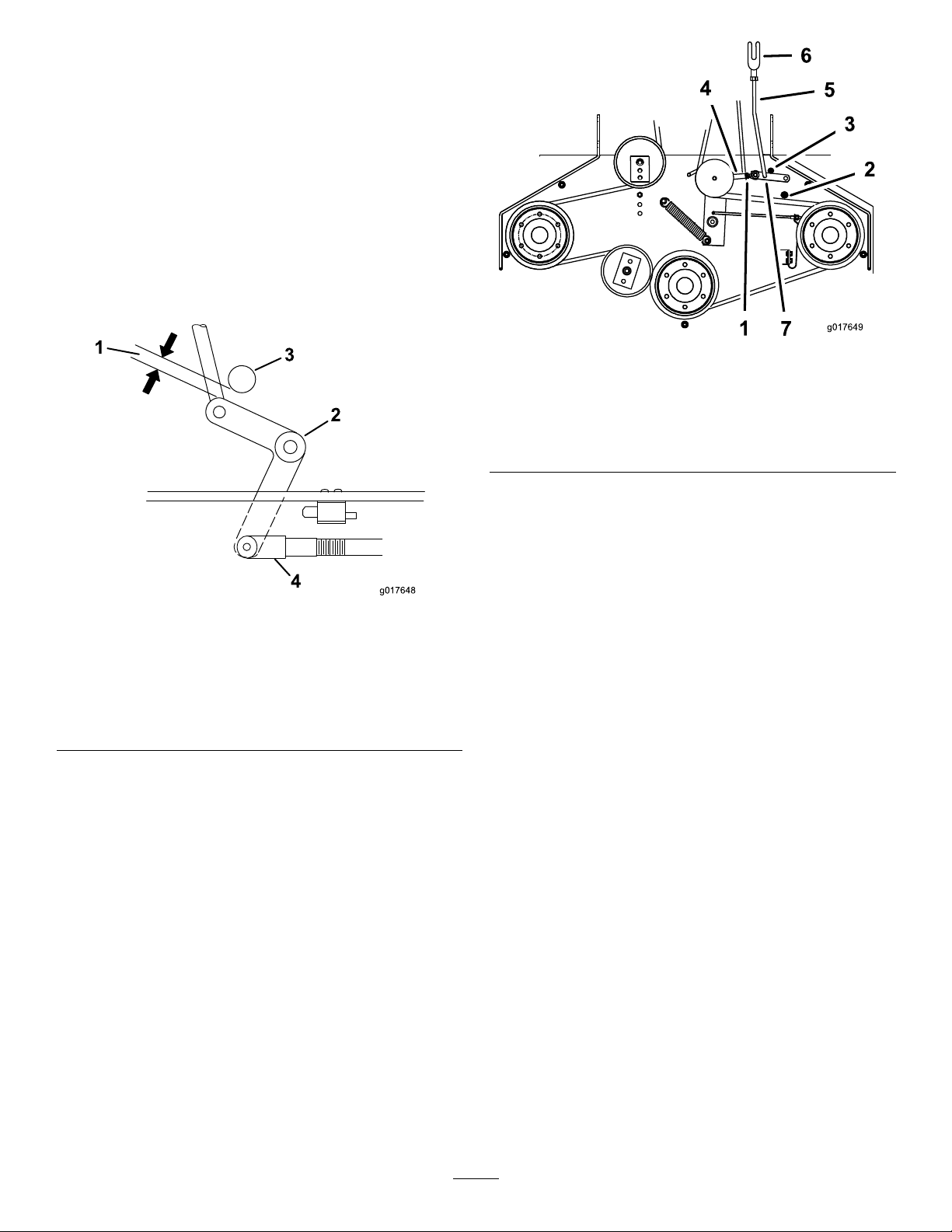
ThePTOengagementlinkageadjustmentislocatedbeneath
thefrontleft-handcorneroftheenginedeck.
1.Disengagetheblade-control(PTO)leverandsetthe
parkingbrakes.
2.Stoptheengineandwaitforallmovingpartstostop
beforeleavingtheoperatingposition.
3.Engagetheblade-controllever(PTO).
4.Adjustthelinkagelengthtowherethelowerendofthe
bellcrankjustclearstheaxlesupportgusset(Figure48).
Figure49
1.Yoke5.Assistarmlink
2.Nut6.Assistarm
3.Rearassistarmstop7.Turnbuckle
4.Frontassistarmstop
8.Toadjusttheassistarmlink,removethehairpincotter
pinfromtheassistarm(Figure49).
9.Loosenthenutagainsttheyoke(Figure48).
10.Removetheassistarmlinkfromtheassistarmand
rotatethelinktoadjustthelength.
Figure48
1.Bellcrank4.Yoke
2.Safetyswitchlocated
underenginedeck
3.Bellcrankjustclearsthe
gussetwiththePTO
engaged
5.Nut
6.Assistarmlink
11.Installtheassistarmlinkintotheassistarmandsecure
itwiththehairpincotterpin(Figure49).
12.Checkiftheassistarmhitsagainstthestopscorrectly.
AdjustingthePTOSafety Switch
5.Makesurethattheassistarmisagainstthe
rear-assist-armstoponthedeck(Figure49).
6.Pushtheblade-controllever(PTO)downtothe
disengagedposition.
7.Theassistarmshouldcontactthefront-assist-armstop
onthedeck.Ifitdoesnotcontact,adjustthebellcrank
sothatitisclosertothegusset(Figure49).
1.Disengagetheblade-control(PTO)leverandsetthe
parkingbrakes.
2.Stoptheengineandwaitforallmovingpartstostop
beforeleavingtheoperatingposition.
3.Disengagetheblade-controllever(PTO).Makesure
thattheassistarmisagainstthefront-assist-armstop.
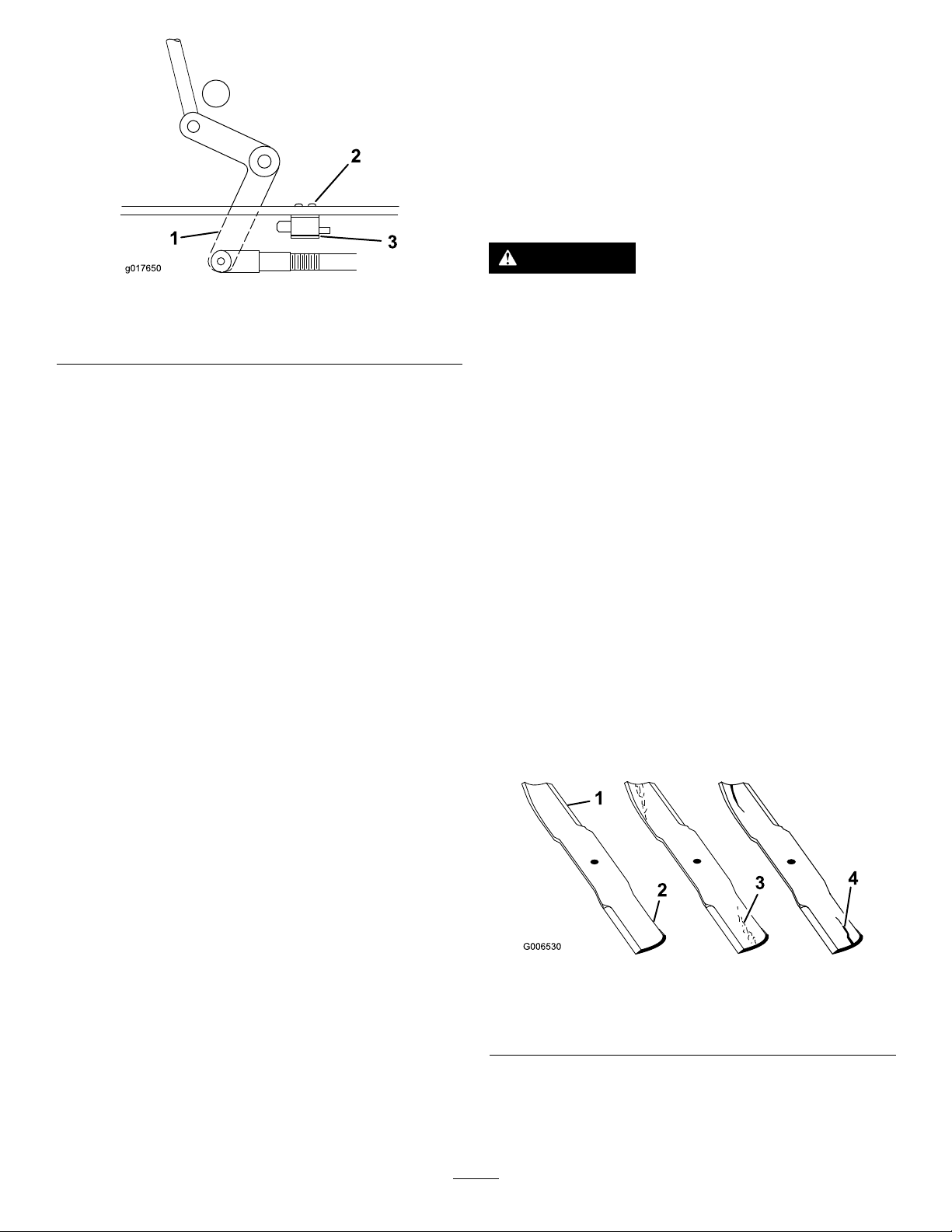
4.Ifneeded,adjusttheblade-safetyswitchbyloosening
theboltsholdingtheswitchbracket(Figure50).
5.Movethemountingbracketuntilthebellcrankpresses
theplungerby6mm(1/4inch);referto(Figure50).
Note:Makesurethatthebellcrankdoesnottouch
theswitchbody;otherwise,damagetotheswitchcould
occur.
6.Tightentheswitchmountingbracket.
36
Page 37
2
3
g017650
1
1.Bellcrank
2.Boltsandnuts
Figure50
3.Switchmountingbracket
4.Switchbody
MowerDeck Maintenance
ServicingtheCuttingBlades
Toensureasuperiorqualityofcut,keepthebladessharp.
Forconvenientsharpeningandreplacement,youmaywant
tokeepextrabladesonhand.
WARNING
Awornordamagedbladecanbreak,andapiece
ofthebladecouldbethrownintotheoperator's
orbystander'sarea,resultinginseriouspersonal
injuryordeath.
•Inspectthebladeperiodicallyforwearor
damage.
•Replaceawornordamagedblade.
PreparingtoInspectorServicethe
Blades
1.Parkthemachineonalevelsurface,disengagethe
blade-controlbail,andsettheparkingbrake.
2.TurntheignitionkeytotheOffposition.
3.Removethekeyanddisconnectthespark-plugwires
fromthesparkplugs.
InspectingtheBlades
ServiceInterval:Beforeeachuseordaily
1.Inspectthecuttingedges(Figure51).Iftheedges
arenotsharporhavenicks,removeandsharpenthe
blades.RefertoSharpeningtheBlades(page39).
Figure51
1.CuttingEdge3.Wear/slotformingin
2.Sail4.Crackinthecurvedarea
2.Inspecttheblades,especiallythecurvedarea(Figure
51).Ifyounoticeanydamage,wear,oraslotforming
37
inthisarea(item3.inFigure51),immediatelyinstall
anewblade.
curvedarea
Page 38
CheckingforBentBlades
1
G024247
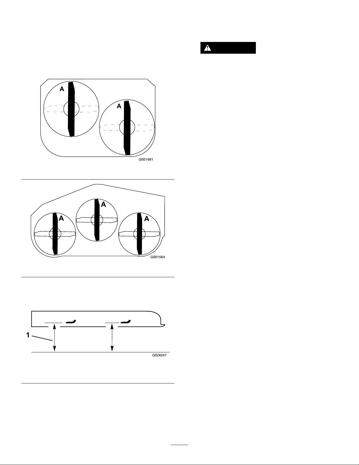
1.Disengagetheblade-controlswitch(PTO)andsetthe
parkingbrake.
inch).Ifthisdimensionexceeds3mm(1/8inch),the
bladeisbentandmustbereplaced.RefertoRemoving
theBlades(page38)andInstallingtheBlades(page39).
2.Stoptheengine,removethekey,andwaitforallmoving
partstostopbeforeleavingtheoperatingposition.
3.Rotatethebladesuntiltheendsfaceforwardand
backward(Figure52).
Figure52
WARNING
Abladethatisbentordamagedcouldbreak
apartandcouldseriouslyinjureorkillyouor
bystanders.
•Alwaysreplacebentordamagedblade
withanewblade.
•Neverleorcreatesharpnotchesinthe
edgesorsurfacesofblade.
RemovingtheBlades
Replacethebladesifyouhitasolidobjectorifthebladesare
outofbalanceorbent.T oensureoptimumperformanceand
continuedsafetyconformanceofthemachine,usegenuine
Tororeplacementblades.Replacementbladesmadebyother
manufacturersmayresultinnon-conformancewithsafety
standards.
1.Holdthebladeboltwithawrench.
2.Removethenut,bladebolt,curvedwasher,blade,
spacers,andthinwasherfromthespindle(Figure55).
Figure53
4.Measurefromalevelsurfacetothecuttingedge,
positionA,oftheblades(Figure54).
Note:Notethisdimension.
Figure54
1.Measurefromthecuttingedgetoalevelsurface
5.Rotatetheoppositeendsofthebladesforward.
6.Measurefromalevelsurfacetothecuttingedgeofthe
bladesatthesamepositionasinstep3.
Note:Thedifferencebetweenthedimensions
obtainedinsteps3and4mustnotexceed3mm(1/8
38
Page 39
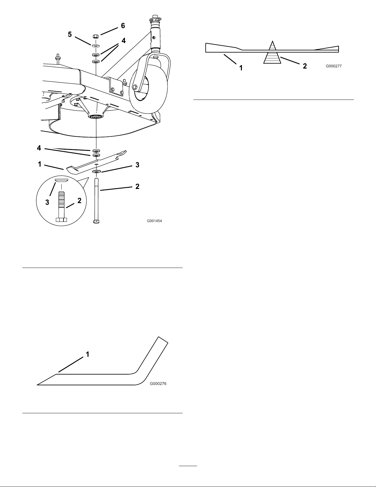
balanced,lesomemetalofftheendofthesailarea
only(Figure57).Repeatthisprocedureuntiltheblade
isbalanced.
Figure57
1.Blade2.Balancer
InstallingtheBlades
1.Installthecurvedwasherandthenthebladeontothe
bolt.Selectthepropernumberofspacer(s)forthe
heightofcut,andslidetheboltintothespindle(Figure
55).
Important:Thecurvedpartoftheblademust
pointupwardtowardtheinsideofthemowerto
ensurepropercutting.
2.Installtheremainingspacer(s)andsecurethemwitha
thinwasherandanut(Figure55).
Figure55
1.Blade
2.Bladebolt5.Thinwasher
3.Curvedwasher
4.Spacer
6.Nut
SharpeningtheBlades
1.Usealetosharpenthecuttingedgeatbothendsof
theblade(Figure56).
Note:Maintaintheoriginalangle.Thebladeremains
balancedifthesameamountofmaterialisremoved
frombothcuttingedges.
3.Torquethebladeboltto101to108N-m(75to
80ft-lb).
Figure56
1.Sharpenatoriginalangle
2.Checkthebalanceofthebladebyputtingitonablade
balancer(Figure57).
Note:Ifthebladestaysinahorizontalposition,the
bladeisbalancedandcanbeused.Ifthebladeisnot
39
Page 40
AdjustingtheBladeBrake
g015594
1
6 2
4
7
3
5
1.DisengagethePTO,turntheignitionkeytotheoff
position,andremovethekey.
2.Waitforallmovingpartstostopbeforeleavingthe
operatingpositionandsettingtheparkingbrake.
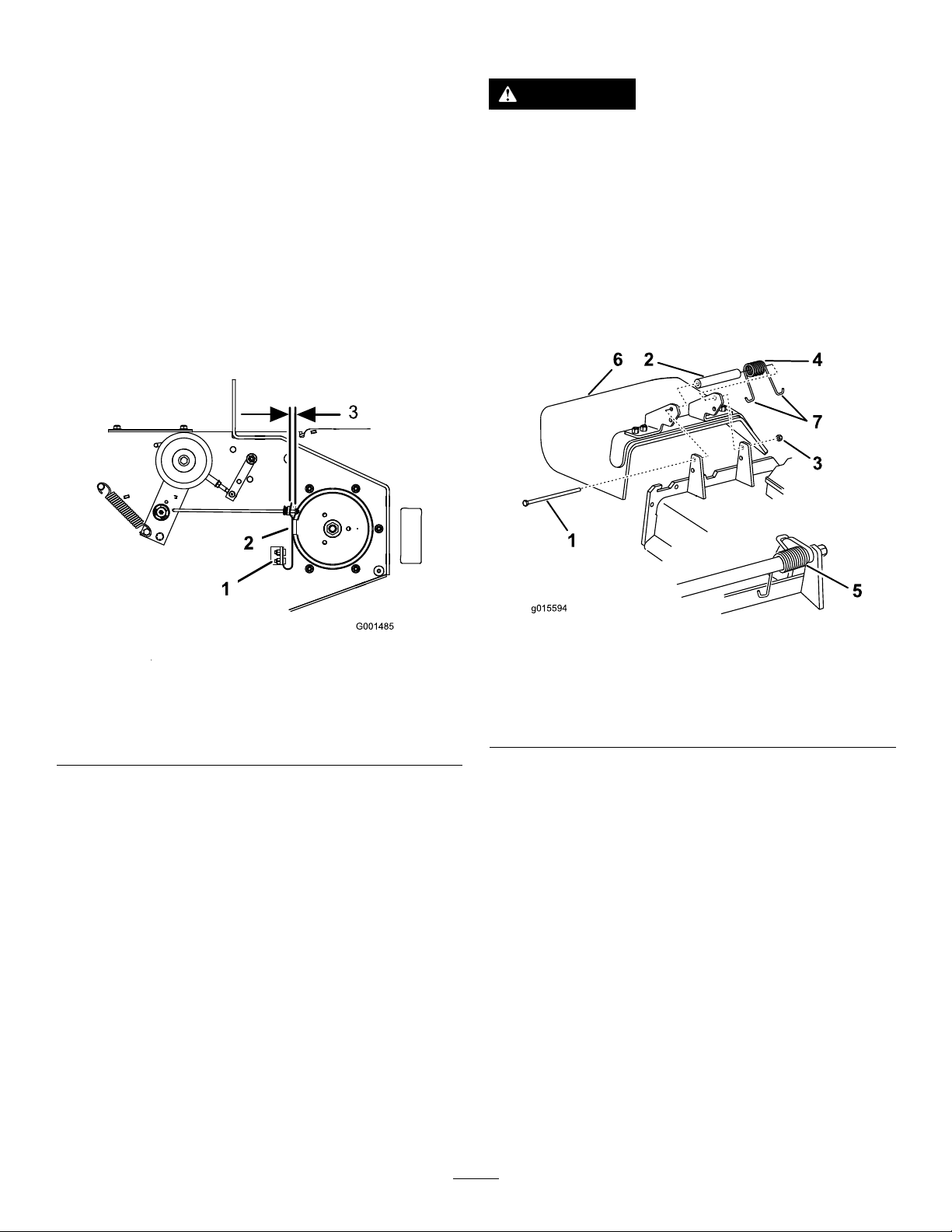
3.Ifnecessary,adjustthespringmountingboltssothat
theblade-brakepadrubsagainstbothsidesofthe
pulleygroove(Figure58).
4.Adjustthenutattheendofthebladebrakeroduntil
thereis3mmto5mm(1/8to3/16inch)betweenthe
nutandthespacer(Figure58).
5.Engagetheblades.
Note:Ensurethatthebladebrakepadnolonger
contactsthepulleygroove.
ReplacingtheGrassDeector
WARNING
Anuncovereddischargeopeningcouldallowthe
lawnmowertothrowobjectsintheoperator'sor
bystander'sdirectionandresultinseriousinjury.
Also,contactwiththebladecouldoccur.
Neveroperatethelawnmowerunlessyouinstalla
coverplate,amulchplate,grassdeectororbagger.
1.Removethelocknut,bolt,springandspacerholding
thedeectortothepivotbrackets(Figure59).
Note:Removethedamagedorworngrassdeector.
Figure58
1.Springmountingbolts3.3mmto5mm(1/8to
2.Blade-brakepad
3/16inch)
Figure59
1.Bolt
2.Spacer6.Grassdeector
3.Locknut
4.Spring
2.Placethespacerandspringontothegrassdeector.
PlaceoneJ-hookendofthespringbehindthedeck
edge.
Note:InstalloneJ-hookendofthespringisinstalled
behindthedeckedgebeforeinstallingtheboltas
showninFigure59.
3.Installtheboltandnut.PlaceoneJ-hookendofthe
springaroundthegrassdeector(Figure59).
Important:Thegrassdeectormustbeable
torotate.Liftthedeectoruptothefullyopen
positionandensurethatitrotatesintothefully
downposition.
5.Springinstalled
7.J-hookendofspring
40
Page 41

Storage
Note:Donotconnectthespark-plugwiresto
thesparkplugs.
1.Disengagethepowertake-off(PTO),settheparking
brake,turntheignitionkeytotheOffposition,and
removethekey.
2.Removegrassclippings,dirt,andgrimefromthe
externalpartsoftheentiremachine,especiallythe
engine.Cleandirtandchafffromtheoutsideofthe
enginecylinder-headnsandtheblowerhousing.
Important:Youcanwashthemachinewithmild
detergentandwater.Donotpressure-washthe
machine.Avoidexcessiveuseofwater,especially
neartheshift-leverplateandtheengine.
3.Checkthebrakes;refertoCheckingtheBrakes(page
32).
4.Servicetheaircleaner;refertoServicingtheAir
Cleaner(page26).
5.Greaseandlubricatethemachine;refertoLubrication
(page25).
6.Changetheengineoil;refertoChangingtheEngine
Oil(page27).
7.Checkthetirepressure;refertoCheckingtheTire
Pressure(page31).
10.Checkandtightenallbolts,nuts,andscrews.Repairor
replaceanypartthatisdamagedorworn.
11.Paintallscratchedorbaremetalsurfaceswithpaint
availablefromyourAuthorizedServiceDealer.
12.Storethemachineinaclean,drygarageorstoragearea.
Removethekeyfromtheignitionswitchandkeepit
inamemorableplace.Coverthemachinetoprotect
itandkeepitclean.
8.Forlong-termstorage:
A.Addstabilizer/conditioneradditivetofuelinthe
tank.
B.Runtheenginetodistributeconditionedfuel
throughthefuelsystem(5minutes).
C.Stoptheengine,allowittocool,anddrainthe
fueltank;refertoServicingtheFuelTankinFuel
SystemMaintenance(page29),oroperateengine
untilitstops.
D.Starttheengineandrunituntilitstops.Repeat
theprocess,withthechokeon,untiltheengine
willnotstart.
E.Disposeoffuelproperly.Recycleitaccordingto
localcodes.
Note:Donotstorestabilizer/conditioned
gasolineover90days.
9.Conditiontheengineforstorageasfollows:
A.Removethesparkplug(s)andcheckthecondition;
refertoRemovingtheSparkPlugs(page28).
B.Pour2tablespoonsofengineoilintotheengine
througheachspark-plughole.
C.Rotatetheengineusingthestarterofthemachine.
Note:Rotatingtheenginedistributestheoil
insidethecylinder.
D.Installthesparkplug(s).
41
Page 42

Troubleshooting
Problem
Theenginewillnotstart,startshard,or
failstokeeprunning.
Theenginelosespower.
PossibleCauseCorrectiveAction
1.Thefueltankisempty.1.Fillthefueltankwithgasoline.
2.Thefuel-shutoffvalveisclosed.2.Openthefuel-shutoffvalve.
3.Thechokeisnotinthecorrectposition.
4.Theaircleanerisdirty.
5.Thespark-plugwireislooseor
disconnected.
6.Thesparkplugispittedorfouled,or
thegapisincorrect.
7.Thereisdirtinthefuellter.7.Replacethefuellter.
8.Dirt,water,orstalefuelisinthefuel
system.
1.Theengineloadisexcessive.1.Reducethegroundspeed.
2.Theaircleanerisdirty.
3.Theoillevelinthecrankcaseislow.3.Addoiltothecrankcase.
4.Thecoolingnsandairpassages
undertheengineblowerhousingare
plugged.
5.Thesparkplugispittedorfouled,or
thegapisincorrect.
6.Theventholeinthefuelcapisplugged.6.Cleanorreplacethefuelcap.
7.Thereisdirtinthefuellter.7.Replacethefuellter.
8.Dirt,water,orstalefuelisinthefuel
system.
3.Closethechokeiftheengineiscold;
openthechokeiftheengineiswarm.
4.Cleanorreplacetheair-cleaner
element.
5.Installthewireonsparkplug.
6.Installanew,correctlygappedspark
plug.
8.ContactanAuthorizedServiceDealer.
2.Cleantheair-cleanerelement.
4.Removetheobstructionfromthe
coolingnsandairpassages.
5.Installanew,correctlygappedspark
plug.
8.ContactanAuthorizedServiceDealer.
Theengineoverheats.
Themachinedoesnotdrive.
Thereisabnormalvibration.
Themachineproducesanunevencutting
height.
1.Theengineloadisexcessive.1.Reducethegroundspeed.
2.Theoillevelinthecrankcaseislow.2.Addoiltothecrankcase.
3.Thecoolingnsandairpassages
undertheengineblowerhousingare
plugged.
1.Theshiftleverisinneutral.1.Movetheshiftlevertoadrivegear
2.Thetractionbeltisworn,loose,or
broken.
3.Thetractionbeltisoffapulley.3.Changethebelt.
4.Theidlerspringisbrokenormissing.4.Replacethespring.
1.One/severalcuttingbladesis/arebent
orunbalanced.
2.Ablademountingboltisloose.2.Tightentheblademountingbolt.
3.Theenginemountingboltsareloose.3.Tightentheenginemountingbolts.
4.Theenginepulley,idlerpulley ,orblade
pulleyisloose.
5.Theenginepulleyisdamaged.
6.Thebladespindleisbent.
1.Theblade(s)is/arenotsharp.1.Sharpentheblade(s).
2.One/severalcuttingblade(s)is/are
bent.
3.Themowerisnotlevel.
4.Theundersideofthemowerisdirty.4.Cleantheundersideofthemower.
5.Thetirepressureisnotcorrect.5.Adjustthetirepressure.
6.Abladespindleisbent.
3.Removetheobstructionfromthe
coolingnsandairpassages.
position.
2.Changethebelt.
1.Installnewcuttingblade(s).
4.Tightentheappropriatepulley .
5.ContactanAuthorizedServiceDealer.
6.ContactanAuthorizedServiceDealer.
2.Installnewcuttingblade(s).
3.Levelthemowerfromside-to-sideand
front-to-rear.
6.ContactanAuthorizedServiceDealer.
42
Page 43

Problem
PossibleCauseCorrectiveAction
Thebladesdonotrotate.
1.Themowerdeckbeltiswornorloose.
2.Themowerdeckbeltisbroken.2.Installanewdeckbelt.
3.Themowerdeckbeltisoffpulley.3.Inspectthebeltandreplaceitifitis
4.Theidlerspringisbrokenormissing.4.Replacethespring.
1.Checkthebelttension.
damaged.Checkthepulleysandidlers
andadjustthebelttension.
43
Page 44
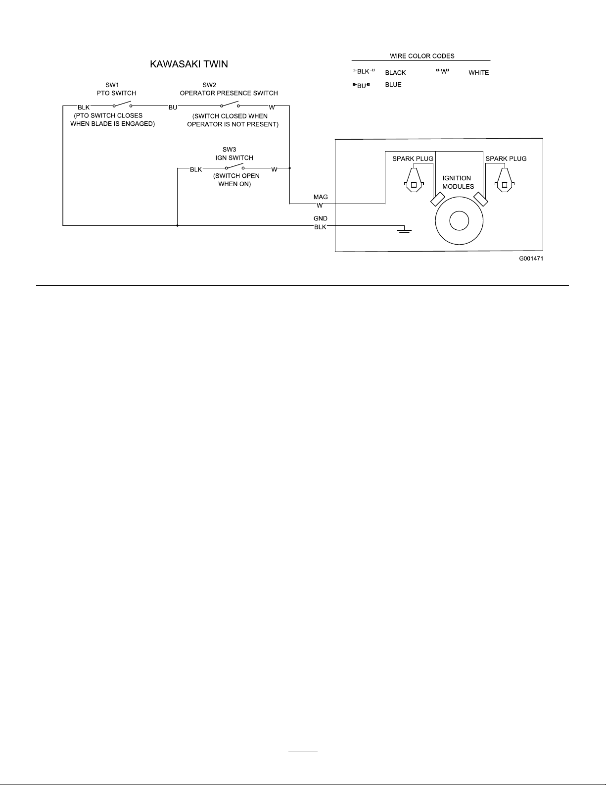
Schematics
ElectricalSchematic(Rev .-A)
44
Page 45

Notes:
45
Page 46

Notes:
46
Page 47

Notes:
47
Page 48

TheToroTotalCoverageWarranty
ALimitedWarranty(seewarrantyperiodsbelow)Contractor
Landscape
Equipment
(LCE)
ConditionsandProductsCovered
TheToroCompanyanditsafliate,T oroWarrantyCompany ,pursuanttoanagreement
betweenthem,jointlypromisetotheoriginalpurchasertorepairtheT oroProducts
listedbelowifdefectiveinmaterialsorworkmanship.
Thefollowingtimeperiodsapplyfromthedateofpurchasebytheoriginalowner:
ProductsWarrantyPeriod
21in.Mowers2yearsResidentialUse
1yearCommercialUse
4
•Engines
Honda–2years
Kawasaki–3years
30in.Mowers2yearsResidentialUse
1yearCommercialUse
4
•Engines
Mid-SizeWalk-BehindMowers
4
•Engines
GrandStand
4
•Engines
•Frame
®
ZMaster
•Engines
2000SeriesMowers
4
•Frame
®
ZMaster
•Engines
•Frame
ZMaster
•Engines
4
®
4
3000SeriesMowers
5000SeriesMowers
®
Mowers
Kawasaki–3years
2years
Kawasaki–3years
5yearsor1,200hours
3years
Lifetime(originalowneronly)
4yearsor500hours
3years
Lifetime(originalowneronly)
5yearsor1,200hours
3years
Lifetime(originalowneronly)
5yearsor1,200hours
KohlerCommand–2years
KohlerEFI–3years
•Frame
®
ZMaster
•Engines
6000SeriesMowers
4
•Frame
®
ZMaster
•Engines
7000SeriesMowers
4
•Frame
®
ZMaster
•Engines
8000SeriesMowers
4
•Frame
Lifetime(originalowneronly)
5yearsor1,200hours
Kawasaki–3years
Lifetime(originalowneronly)
5yearsor1,200hours
2years
Lifetime(originalowneronly)
2yearsor1,200hours
2years
Lifetime(originalowneronly)
AllMowers
•Battery90daysPartsandLabor
1yearPartsonly
•BeltsandTires90days
•Attachments1year
1
Residentialusemeansuseoftheproductonthesamelotasyourhome.Useatmorethanone
locationisconsideredcommercialuseandthecommercialwarrantywouldapply.
2
Whicheveroccursrst.
3
LifetimeFrameW arranty-Ifthemainframe,consistingofthepartsweldedtogethertoformthe
tractorstructurethatothercomponentssuchastheenginearesecuredto,cracksorbreaksin
normaluse,itwillberepairedorreplaced,atToro'soption,underwarrantyatnocostforpartsand
labor.Framefailureduetomisuseorabuseandfailureorrepairrequiredduetorustorcorrosion
arenotcovered.
4
SomeenginesusedonToroProductsarewarrantedbytheenginemanufacturer .
1
1
2
3
2
3
2
3
2
3
2
3
2
3
2
3
InstructionsforObtainingWarrantyService
IfyouthinkthatyourT oroProductcontainsadefectinmaterialsorworkmanship,
followthisprocedure:
1.ContactanyAuthorizedToroServiceDealertoarrangeserviceattheir
dealership.T olocateadealerconvenienttoyou,refertotheY ellowPagesof
yourtelephonedirectory(lookunder“LawnMowers”)oraccessourwebsite
atwww.Toro.com.Youmayalsocallthenumberslistedinitem#3tousethe
24-hourT oroDealerlocatorsystem.
2.Bringtheproductandyourproofofpurchase(salesreceipt)totheService
Dealer.Thedealerwilldiagnosetheproblemanddetermineifitiscovered
underwarranty.
3.IfforanyreasonyouaredissatisedwiththeServiceDealer’sanalysisorwith
theassistanceprovided,contactusat:
RLCCustomerCareDepartment
ToroWarrantyCompany
811 1LyndaleAvenueSouth
Bloomington,MN55420-1 196
888-865-5676(U.S.Customers)
888-865-5691(Canadacustomers)
OwnerResponsibilities
YoumustmaintainyourT oroProductbyfollowingthemaintenanceprocedures
describedintheOperator'sManual.Suchroutinemaintenance,whetherperformedby
adealerorbyyou,isatyourexpense.
ItemsandConditionsNotCovered
Thereisnootherexpresswarrantyexceptforspecialemissionsystemcoverage
andenginewarrantycoverageonsomeproducts.Thisexpresswarrantydoesnot
coverthefollowing:
•Costofregularmaintenanceserviceorparts,suchaslters,fuel,lubricants,oil
changes,sparkplugs,airltersbladesharpeningorwornblades,cable/linkage
adjustments,orbrakeandclutchadjustments
•Componentsfailingduetonormalwear
•Anyproductorpartwhichhasbeenalteredormisusedorneglectedandrequires
replacementorrepairduetoaccidentsorlackofpropermaintenance
•Pickupanddeliverycharges
•RepairsorattemptedrepairsbyanyoneotherthananAuthorizedT oroService
Dealer
•Repairsnecessaryduetofailuretofollowrecommendedfuelprocedure(consult
Operator'sManualformoredetails)
–Removingcontaminantsfromthefuelsystemisnotcovered
–Useofoldfuel(morethanonemonthold)orfuelwhichcontainsmorethan
10%ethanolormorethat15%MTBE
–Failuretodrainthefuelsystempriortoanyperiodofnon-useoverone
month
GeneralConditions
AllrepairscoveredbythesewarrantiesmustbeperformedbyanAuthorizedT oro
ServiceDealerusingT oroapprovedreplacementparts.
NeitherTheToroCompanynorToroWarrantyCompanyisliableforindirect,
incidentalorconsequentialdamagesinconnectionwiththeuseoftheT oro
Productscoveredbythiswarranty ,includinganycostorexpenseofproviding
substituteequipmentorserviceduringreasonableperiodsofmalfunctionor
non-usependingcompletionofrepairsunderthiswarranty.
Allimpliedwarrantiesofmerchantability(thattheproductistforordinaryuse)
andtnessforuse(thattheproductistforaparticularpurpose)arelimitedto
thedurationoftheexpresswarranty.
Somestatesdonotallowexclusionsofincidentalorconsequentialdamages,
orlimitationsonhowlonganimpliedwarrantylasts,sotheaboveexclusions
andlimitationsmaynotapplytoyou.
Thiswarrantygivesyouspeciclegalrights,andyoumayalsohaveotherrights
whichvaryfromstatetostate.
CountriesOtherthantheUnitedStatesorCanada
CustomerswhohavepurchasedT oroproductsoutsidetheUnitedStatesorCanadashouldcontacttheirT oroDistributor(Dealer)toobtainguaranteepoliciesforyourcountry,
province,orstate.IfforanyreasonyouaredissatisedwithyourDistributor'sserviceorhavedifcultyobtainingguaranteeinformation,contacttheToroimporter.Ifallother
remediesfail,youmaycontactusatT oroWarrantyCompany.
AustralianConsumerLaw:AustraliancustomerswillnddetailsrelatingtotheAustralianConsumerLaweitherinsidetheboxoratyourlocalT oroDealer .
374-0252RevG
 Loading...