


FormNo.3412-564RevB
30inStand-OnAerator
ModelNo.39519—SerialNo.400000000andUp
Registeratwww.T oro.com.
OriginalInstructions(EN)
*3412-564*B
ThissparkignitionsystemcomplieswithCanadian
ICES-002
Important:Thisengineisnotequippedwith
asparkarrestermufer.Itisaviolationof
CaliforniaPublicResourceCodeSection4442to
useoroperatetheengineonanyforest-covered,
brush-covered,orgrass-coveredland.Other
statesorfederalareasmayhavesimilarlaws.
TheenclosedEngineOwner'sManualis
suppliedforinformationregardingtheUS
EnvironmentalProtectionAgency(EPA)and
theCaliforniaEmissionControlRegulationof
emissionsystems,maintenance,andwarranty.
Replacementsmaybeorderedthroughtheengine
manufacturer.
WARNING
CALIFORNIA
Proposition65Warning
Theengineexhaustfromthisproduct
containschemicalsknowntotheStateof
Californiatocausecancer,birthdefects,
orotherreproductiveharm.
Batteryposts,terminals,andrelated
accessoriescontainleadandlead
compounds,chemicalsknownto
theStateofCaliforniatocause
cancerandreproductiveharm.Wash
handsafterhandling.
Useofthisproductmaycauseexposure
tochemicalsknowntotheStateof
Californiatocausecancer,birthdefects,
orotherreproductiveharm.
Visitwww.Toro.comforproductsafetyandoperation
trainingmaterials,accessoryinformation,helpnding
adealer,ortoregisteryourproduct.
Wheneveryouneedservice,genuineToroparts,or
additionalinformation,contactanAuthorizedService
DealerorToroCustomerServiceandhavethemodel
andserialnumbersofyourproductready.Figure1
identiesthelocationofthemodelandserialnumbers
ontheproduct.Writethenumbersinthespace
provided.
g020219
Figure1
1.Locationofthemodelandserialnumbers
ModelNo.
SerialNo.
Thismanualidentiespotentialhazardsandhas
safetymessagesidentiedbythesafety-alertsymbol
(Figure2),whichsignalsahazardthatmaycause
seriousinjuryordeathifyoudonotfollowthe
recommendedprecautions.
Introduction
Thisaeratorisintendedtobeusedbytrained
operatorsinresidentialandcommercialapplications.
Itisprimarilydesignedforaeratingareasof
well-maintainedlawnsonresidentialgrounds,parks,
sportselds,andcommercialgrounds.Usingthis
productforpurposesotherthanitsintendedusecould
provedangeroustoyouandbystanders.
Readthisinformationcarefullytolearnhowtooperate
andmaintainyourproductproperlyandtoavoid
injuryandproductdamage.Youareresponsiblefor
operatingtheproductproperlyandsafely .
©2020—TheToro®Company
8111LyndaleAvenueSouth
Bloomington,MN55420
Figure2
Safety-alertsymbol
Thismanualuses2wordstohighlightinformation.
Importantcallsattentiontospecialmechanical
informationandNoteemphasizesgeneralinformation
worthyofspecialattention.
2
g000502
Contactusatwww.Toro.com.
PrintedintheUSA
AllRightsReserved

Contents
Safety.......................................................................4
SafeOperatingPractices....................................4
AeratorSafety....................................................6
SlopeIndicator...................................................7
SafetyandInstructionalDecals..........................8
Setup......................................................................12
1CheckingTirePressure..................................12
2ServicingtheBattery......................................12
3CheckingFluidLevels....................................13
4RemovingtheCylinderStop...........................14
ProductOverview...................................................15
Controls...........................................................15
Specications..................................................18
Operation................................................................18
CheckingtheEngine-OilLevel..........................18
AddingFuel......................................................19
LubricatingtheChains......................................20
CheckingtheSafety-InterlockSystem..............22
CheckingforLooseHardware...........................22
OperatingtheMachine.....................................22
TransportingtheMachine.................................25
LoadingtheMachine........................................26
Maintenance...........................................................27
RecommendedMaintenanceSchedule(s)...........27
Pre-MaintenanceProcedures..............................28
PreparingfortheMachinefor
Maintenance.................................................28
AccessingtheConsoleCompartment...............28
Lubrication..........................................................29
LubricatingtheGreaseFittings.........................29
LubricatingtheCasters.....................................30
EngineMaintenance...........................................32
ServicingtheAirCleaner..................................32
ServicingtheEngineOil....................................33
CheckingtheSparkPlugs.................................35
ServicingtheSparkPlug...................................35
CheckingtheSparkArrester(if
equipped)......................................................36
FuelSystemMaintenance...................................36
ServicingtheFuelFilter....................................36
ElectricalSystemMaintenance...........................37
ServicingtheBattery.........................................37
ServicingtheFuses..........................................39
DriveSystemMaintenance..................................39
CheckingtheAirPressureintheTires...............39
CheckingtheWheelHubNuts..........................39
CheckingtheT orqueoftheWheelLug
Nuts..............................................................39
AdjustingtheCasterPivotBearings
Pre-Load.......................................................40
MaintainingtheChain.......................................40
CheckingtheTransmissionOutputShaftNut
Torque...........................................................41
BrakeMaintenance.............................................42
AdjustingtheParkingBrake..............................42
AdjustingtheBrakeSwitch...............................42
BeltMaintenance................................................43
CheckingtheConditionandTensionofthe
Belts..............................................................43
AdjustingtheAuxiliaryPumpDrive
Belt................................................................43
ReplacingtheTransmission-DriveBelt.............43
ControlsSystemMaintenance.............................44
AdjustingtheTraction-ControlLinkage.............44
HydraulicSystemMaintenance...........................45
MaintainingtheAuxiliaryHydraulic
System..........................................................45
MaintainingtheTransmission...........................47
TineMaintenance.................................................50
CheckingtheTines...........................................50
AdjustingtheTine-DriveChain.........................50
Cleaning..............................................................51
CleaningtheEngineandtheExhaust
SystemArea.................................................51
RemovingtheEngineShroudsandCleaning
theCoolingFins............................................51
CleaningtheDebrisfromtheMachine...............51
WasteDisposal.................................................51
Storage...................................................................52
Troubleshooting......................................................53
Schematics.............................................................55
3

Safety
Improperuseormaintenancecanresultininjury.
Toreducethepotentialforinjury ,complywith
thesesafetyinstructions,andpayattentiontothe
safety-alertsymbol,whichmeansCaution,Warning,
orDanger—personalsafetyinstruction.Failureto
complywiththeinstructionsmayresultinpersonal
injuryordeath.
WARNING
Removalormodicationoforiginal
equipment,partsand/oraccessoriesmay
alterthewarranty,controllability,andsafety
ofthemachine.Unauthorizedmodications
totheoriginalequipmentorfailuretouse
originalToropartscouldleadtoserious
injuryordeath.Unauthorizedchangestothe
machine,engine,fuelorventingsystem,may
violateapplicablesafetystandardssuchas:
ANSI,OSHAandNFPAand/orgovernment
regulationssuchasEPAandCARB.
Replaceallpartsincluding,butnotlimitedto,
tires,belts,andfuelsystemcomponentswith
originalT oroparts.
Important:Thismachinewasmanufactured
accordingtotheappropriateregulatorystandards
ineffectatthetimeofmanufacture.Modifying
thismachineinanywaymaycauseittobe
outofcompliancewiththosestandardsand
withtheinstructionsinthisOperator’sManual.
Modicationstothismachineshouldonlybe
madebyeitherthemanufactureroranAuthorized
ToroDealer.
Thisproductiscapableofinjuringyourhandsand
feet.Followallsafetyinstructionstoavoidserious
injuryordeath.
Theowner/usercanpreventandisresponsiblefor
accidentsorinjuriesoccurringtopeople,ordamage
toproperty.
Anyuseofthismachineotherthanaeratingturfgrass
couldprovedangeroustotheuserandbystanders.
Important:Theadditionofattachmentsmade
byothermanufacturersthatdonotmeetANSI
certicationmaycausenoncomplianceofthis
machine.
SafeOperatingPractices
ThefollowinginstructionsarefromANSIstandard
B71.4-2012.
Training
•ReadtheOperator'sManualandothertraining
material.
Note:Iftheoperator(s)ormechanic(s)cannot
readthemanuallanguage,itistheowner's
responsibilitytoexplainthismaterialtothem.
•Becomefamiliarwiththesafeoperationofthe
equipment,operatorcontrols,andsafetysigns.
•Alloperatorsandmechanicsshouldbetrained.
Theownerisresponsiblefortrainingtheusers.
•Neverletchildrenoruntrainedpeopleoperateor
servicetheequipment.
Note:Localregulationsmayrestricttheageof
theoperator.
•Theowner/usercanpreventandisresponsible
foraccidentsorinjuriesoccurringtopeopleor
damagetoproperty.
Preparation
•Evaluatetheterraintodeterminewhataccessories
andattachmentsareneededtoproperlyand
safelyperformthejob.Onlyuseaccessoriesand
attachmentsapprovedbythemanufacturer.
•Wearappropriateclothing;includingsafety
glasses,longpants,substantialslip-resistant
footwear,gloves,andhearingprotection.
•Tiebacklonghair.Donotwearjewelry.
•Inspecttheareawheretheequipmentistobe
usedandensurethatallobjectsareremovedfrom
theareabeforeuse.
•Checkthattheoperator'spresencecontrols,safety
switches,andshieldsareattachedandfunctioning
properly.Donotoperatethemachineunlessthey
arefunctioningproperly.
Operation
•Lightningcancausesevereinjuryordeath.If
lightningisseen,orthunderisheardinthearea,
donotoperatethemachine;seekshelter.
•Donotrunanengineinanenclosedarea.
•Onlyoperateinwell-litareas,keepingawayfrom
holesandhiddenhazards.
•Ensurethatalldrivesareinneutralandthatthe
parkingbrakeisengagedbeforestartingengine.
Onlystarttheenginefromtheoperator’sposition.
•Makesurethatyouhavegoodfootingwhileusing
thismachine,especiallywhenbackingup.
4

Note:Reducedfootingcouldcauseslipping.
•Slowdownanduseextracareonhillsides.Be
suretotravelsidetosideonhillsides.Turf
conditionscanaffectthestabilityofthemachine.
Usecautionwhileoperatingneardrop-offs.
•Slowdownandusecautionwhenmakingturns
andwhenchangingdirectionsonslopes.
•Donotoperatethemachinewithouttheshields
orotherguardssecurelyinplace.Besureall
interlocksareattached,adjustedproperly,and
functioningproperly.
•Donotchangetheenginegovernorsettingor
overspeedtheengine.
•Beforeleavingtheoperator’sposition:
–Stoponlevelground.
–Disengagetheparkingbrake(ifprovided).
–Shutofftheengine.
•Stoponlevelground,disengagedrives,engage
theparkingbrake(ifprovided),shutofftheengine
beforeleavingtheoperator'spositionforany
reason.
•Stopequipmentandinspectthetinesafterstriking
objectsorifanabnormalvibrationoccurs.Make
thenecessaryrepairsbeforeresumingoperations.
•Keepyourhandsandfeetawayfromthetine
assembly.
•Lookbehindanddownbeforebackingupto
ensureaclearpath.
•Keeppetsandbystandersawayfromanoperating
machine.
•Slowdownandusecautionwhenmakingturns
andcrossingroadsandsidewalks.Fullyraisethe
tinesifyouarenotaerating.
•Donotoperatethemachinewhileill,tired,or
undertheinuenceofalcoholordrugs.
•Usecarewhenapproachingblindcorners,shrubs,
trees,orotherobjectsthatmayobscurevision.
SafeHandlingofFuels
•Toavoidpersonalinjuryorpropertydamage,use
extremecareinhandlingfuel.Fuelisextremely
ammableandthevaporsareexplosive.
•Useonlyanapprovedfuelcontainer.
•Donotremovethefuelcaporaddfuelwiththe
enginerunning.
•Allowtheenginetocoolbeforefueling.
•Neverrefuelordrainthemachineindoorsanddo
notsmokewhilerefuelingordraining.
•Donotstorethemachineorfuelcontainerwhere
thereisanopename,spark,orpilotlightsuchas
onawaterheateroronotherappliances.
•Donotllcontainersinsideavehicle,onatruck,
oronatrailerbedwithaplasticliner.Alwaysplace
containersonthegroundawayfromyourvehicle
beforelling.
•Removeequipmentfromthetruckortrailerand
fuelitontheground.Ifthisisnotpossible,
thenaddfuelwithsuchequipmentasaportable
container,ratherthanfromafuel-dispensernozzle.
•Keepthenozzleincontactwiththerimofthefuel
tankorcontaineropeningatalltimesuntilfueling
iscomplete.Donotuseanozzlelockopendevice.
•Iffuelisspilledonclothing,changeyourclothing
immediately.
•Donotoverllfueltank.Replacefuelcapand
tightensecurely.
MaintenanceandStorage
•Donotallowuntrainedpersonneltoservice
machine.
•Donottouchequipmentorattachmentpartswhich
maybehotfromoperation.Allowallofthepartsof
themachinetocoolbeforeattemptingtomaintain,
adjust,orservicethemachine.
•Keepyourhandsandfeetawayfrommoving
parts.Ifpossible,donotmakeadjustmentswith
theenginerunning.
•Disengagethedrives,raisethetines,engagethe
parkingbrake,shutofftheengine,andremove
thekeyordisconnectthespark-plugwire.Waitfor
allmovementtostopbeforeadjusting,cleaning,
orrepairing.
•Disconnectthebatteryorremovethespark-plug
wirebeforemakinganyrepairs.Disconnectthe
negativeterminalrstandthepositiveterminal
last.Reconnectthepositiverstandnegativelast.
•Usecarewhencheckingthetines.Wrapthetine(s)
orweargloves,andusecautionwhenservicing
them.Onlyreplacetines;donotstraightenorweld
them.
•Cleangrass,dirt,anddebrisfromthetines,drives,
mufers,andenginetohelppreventres.
•Cleanupoilorfuelspills.
•Parkthemachineonlevel,hardground.Never
allowuntrainedpersonneltoservicemachine.
•Usejackstandstosupportcomponentswhen
required.
•Carefullyreleasepressurefromcomponentswith
storedenergy.
•Lettheenginecoolbeforestoring.
•Keepallpartsingoodworkingconditionandall
hardwaretightened.Replaceallwornordamaged
decals.
5

Hauling
•Usecarewhenloadingorunloadingthemachine
intoatraileroratruck.
•Donotaerateslopesgreaterthan15degrees.
•Avoidsuddenstartsandstopswhenaeratinguphill
becausethemachinemaytipbackward.
•Usefull-widthrampsforloadingmachineintoa
traileroratruck.
•Tiethemachinedownsecurelyusingstraps,
chains,cable,orropes.Bothfrontandrearstraps
shouldbedirecteddownandoutwardfromthe
machine.
AeratorSafety
Thefollowinglistcontainssafetyinformationspecic
toToroproductsandothersafetyinformationyou
mustknow.
GeneralOperation
•Checkcarefullyforoverheadclearances(i.e.
branches,doorways,electricalwires,etc.)before
operatingunderanyobjects,anddonotcontact
them.
•Usecautionwhenyouareridingontheplatform
anddrivingthemachineovercurbs,rocks,roots,
orotherobstructions.
•Donotjerkthecontrols;useasteadymotion.
•Donotcarrypassengers.
•Donotcarryequipmentonthemachine.
SlopeOperation
Useextremecautionwhenaeratingand/orturning
onslopesaslossoftractionand/ortip-overcould
occur.Theoperatorisresponsibleforsafeoperation
onslopes.
•UseFigure3tohelpyoudeterminetheappropriate
slopeangleofareatoaerate
Note:Themachineismorestablegoinguphill
withthetinesraised.
•Keepallmovementonslopesslowandgradual.
•Donotmakesuddenchangesinspeedor
direction.
•Reducethetine-downpressuretopreventthe
drivetiresfromraisingoffthegroundandto
preventthefronttiresfromraisingofftheground
whileaeratinguphill.
•Followthemanufacturer’srecommendationsfor
wheelweightsorcounterweightstoimprove
stability.
•Useextracarewithattachments.
Note:Useofattachmentscanchangethestability
ofthemachine.
Service
•Toensureoptimumperformanceandcontinued
safetycerticationofthemachine,useonly
genuineT ororeplacementpartsandaccessories.
Replacementpartsandaccessoriesmadeby
othermanufacturerscouldbedangerous,and
suchusecouldvoidtheproductwarranty.
•Neverremoveortamperwithsafetydevices.
Checktheirproperoperationregularly.Neverdo
anythingtointerferewiththeintendedfunctionofa
safetydeviceortoreducetheprotectionprovided
byasafetydevice.
•Checkbrakeoperationfrequently.Adjustand
serviceasrequired.
•Removeormarkobstaclessuchasrocks,tree
limbs,etc.fromtheaeratingarea.
•Watchforholes,rutsorbumps.
Note:T allgrasscanhideobstacles.
•Usecautionneardrop-offs,ditches,or
embankments.
Note:Themachinecouldsuddenlyturnoverifa
wheelgoesovertheedgeofaclifforditch,orif
anedgecavesin.
•Beawarethatoperatingonwetgrass,across
steepslopesordownhillmaycausethemachine
tolosetraction.Lossoftractiontothedrivewheels
mayresultinslidingandalossofbrakingand
steering.
6

SlopeIndicator
Figure3
Thispagemaybecopiedforpersonaluse.
1.Themaximumslopeyoucansafelyoperatethemachineonis15degrees.Usetheslopecharttodeterminethedegreeofslope
ofhillsbeforeoperating.Donotoperatethismachineonaslopegreaterthan15degrees.Foldalongtheappropriateline
tomatchtherecommendedslope.
2.Alignthisedgewithaverticalsurface,atree,building,fencepole,etc.
3.Exampleofhowtocompareslopewithfoldededge.
7
g011841
SafetyandInstructionalDecals
Safetydecalsandinstructionsareeasilyvisibletotheoperatorandarelocatednearanyarea
ofpotentialdanger.Replaceanydecalthatisdamagedormissing.
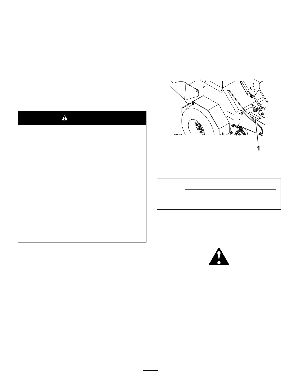
93-6686
decal93-6686
1.Hydraulicuid2.ReadtheOperator's
115-2047
1.Warning—donottouchthehotsurface.
116-9391
Manual.
decal121-6150
121-6150
decal115-2047
1.Cuttinghazardofhandandfoot–stayawayfrommoving
parts.
decal121-6161
121-6161
1.Entanglementhazard,belt—stayawayfrommovingparts;
keepallguardsinplace.
decal116-9391
117-2718
120-9570
1.Warning—stayawayfrommovingparts,keepallguards
andshieldsinplace.
decal121-6162
121-6162
decal117-2718
decal120-9570
1.Cutting/dismembermenthazardofhandorfoot—lower
thetinestotheground;readtheOperator’sManualfor
disassemblyprocedure.
8
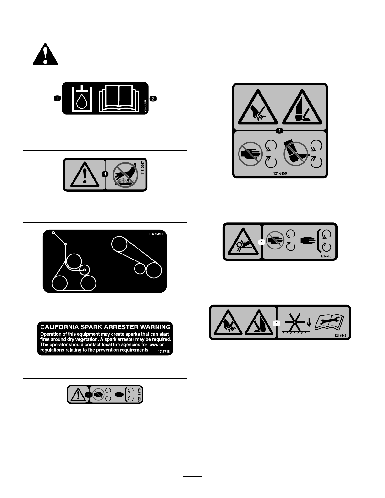
121-6163
1.Presstolowerthetines.2.Releasetoraisethetines.
decal126-2054
126-2054
1.Wheellugnuttorque129N∙m(95ft-lb)(4x)
2.Wheelhubnuttorque319N∙m(235ft-lb)
3.ReadandunderstandtheOperator’sManualbefore
performinganymaintenance;checkthetorqueevery100
hours.
decal121-6163
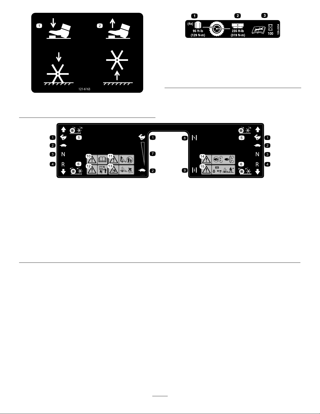
decal121-6164
121-6164
1.Fast6.Wheelsandtinesrotatewhenmoving
backward
2.Slow7.Continuousvariablesetting
3.Neutral
4.Reverse
5.Wheelsandtinesrotatewhenmoving
8.Choke—on
9.Choke—off14.Warning—stayawayfrommoving
10.Warning—readtheOperator’sManual.15.Warning—shutofftheengine,engage
forward
11.Warning—keepbystandersaway .
12.Warning—donotoperatethemachine
unlessyouaretrained.
13.Thrownobjecthazard—pickupdebris
beforeoperatingthemachine.
parts;keepallguardsinplace.
theparkingbreak,andremovethekey
beforeleavingthemachine.
9
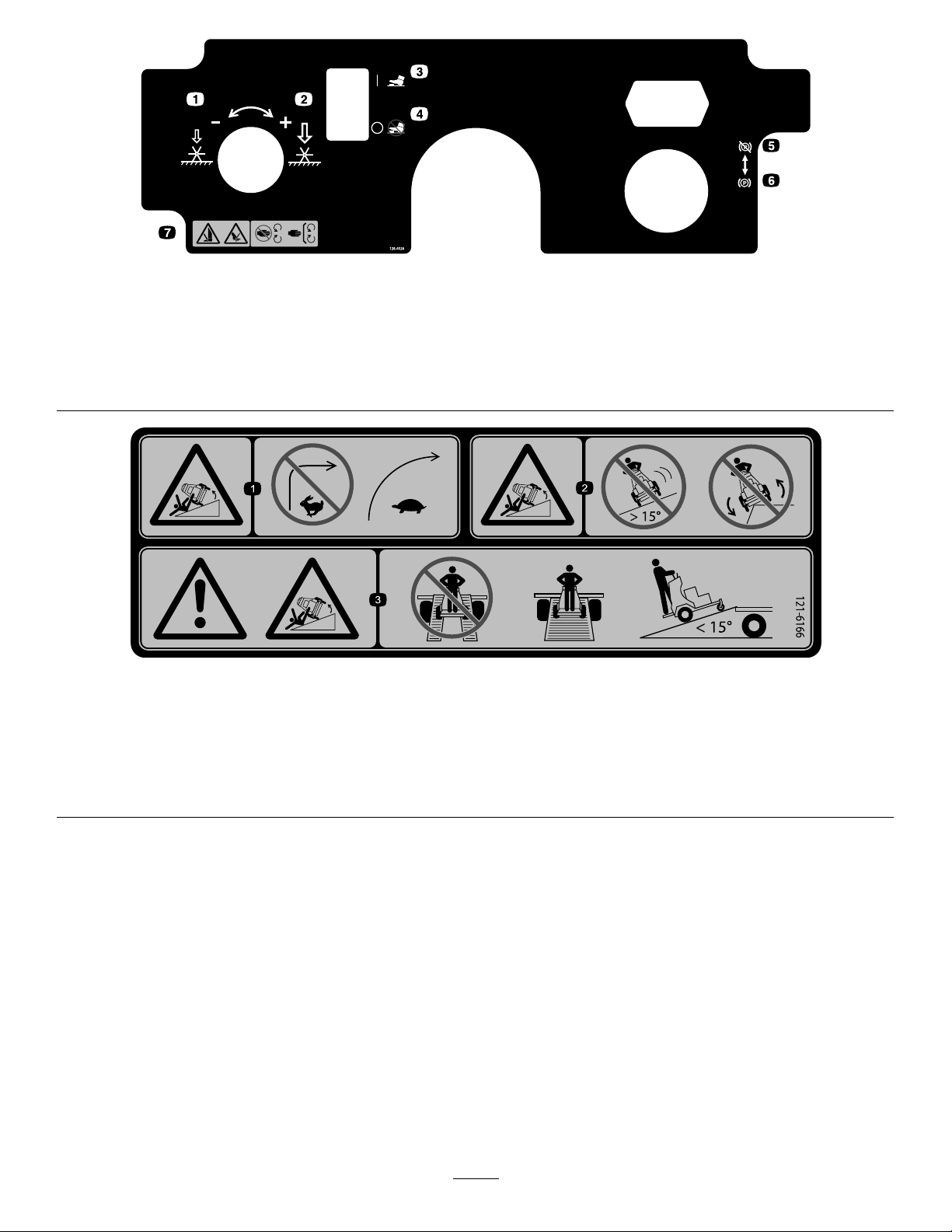
126-4528
1.Rotatecounterclockwisetodecreasepressure5.Parkingbrake-release
2.Rotateclockwisetoincreasepressure6.Parkingbrake-engage
3.On-tinegroundengagementfootswitch7.Cutting/dismembermenthazardofhandorfoot,tines–stay
awayfrommovingparts;keepallguardsinplace
4.Off-tinegroundengagementfootswitch
121-6166
decal126-4528
decal121-6166
1.Tippinghazard—donotturnsharplywhiletravellingfast;slow
downandturngradually.
2.Tippinghazard—donotoperatethemachineonslopes
greaterthan15degrees;donotoperatethemachinenear
drop-offs.
3.Warning;tippinghazard—donotusesplitramps;usefull
widthrampstoloadamachinefortransport;usealoading
rampatamaximumof15degrees.
10
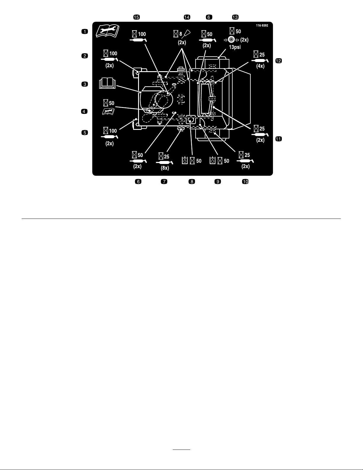
116–9392
1.Readtheinstructionsbeforeservicingorperformingmaintenance;readtheOperator’sManualforinformationonlubricating
themachine.
decal116-9392
11

Setup
MediaandAdditionalParts
Description
Operator'sManual
Key2
1
CheckingTirePressure
NoPartsRequired
Procedure
1.Checkthetirepressureinthedrivetires.
Note:Properinationfordrivetiresis83to97
kPa(12to14psi).
2.Adjustthetirepressureifnecessary.
Qty.
Use
1
Readbeforeoperatingthemachine.
Startthemachine.
2
ServicingtheBattery
NoPartsRequired
Procedure
Note:Themachineisshippedwithalled,lead-acid
battery.
DANGER
Chargingorjumpstartingthebatterymay
produceexplosivegases.Batterygasescan
explodecausingseriousinjury.
•Keepsparks,ames,orcigarettesaway
frombattery.
•Ventilatewhenchargingorusingbatteryin
anenclosedspace.
•Makesurethattheventingpathofbattery
isalwaysopenoncethebatteryislled
withacid.
•Alwaysshieldeyesandfacefrombattery.
DANGER
Batteryelectrolytecontainssulfuricacid,
whichispoisonousandcancausesevere
burns.Swallowingelectrolytecanbefatalor
ifittouchesskincancausesevereburns.
•Wearsafetyglassestoshieldyoureyes
andrubberglovestoprotectyourskinand
clothingwhenhandlingelectrolyte.
•Donotswallowelectrolyte.
•Intheeventofanaccident,ushwithwater
andcalladoctorimmediately.
12
1.TurnthekeyintheignitionswitchtotheOFF
positionandremovethekey.
2.Measurethevoltageofthebatterywitha
voltmeter.
3.Usethetablebelowtolocatethechargestate
orthebattery,andifneeded,thebattery-charger
settingandchargingintervalrecommendedto
chargethebatteryto12.6Vorgreater.
Important:Makesurethatthenegative
batterycableisdisconnectedandthe
batterychargerusedforchargingthebattery
hasanoutputof16Vand7Aorlessto
avoiddamagingthebattery(seechartfor
recommendedchargersettings).
BatteryChargeTable
Voltage
Reading
12.6or
greater
12.4–12.6
12.2–12.4
12.0–12.2
11.7–12.0
11.7orless
Percent
Charge
100%16volts/
75–100%16volts/
50–75%16volts/
25–50%14.4volts/
0–25%14.4volts/
0%14.4volts/
Maximum
Charger
Settings
7amps
7amps
7amps
4amps
4amps
2amps
Charging
Interval
NoCharging
Required
30Minutes
1Hour
2Hours
3Hours
6Hoursor
More
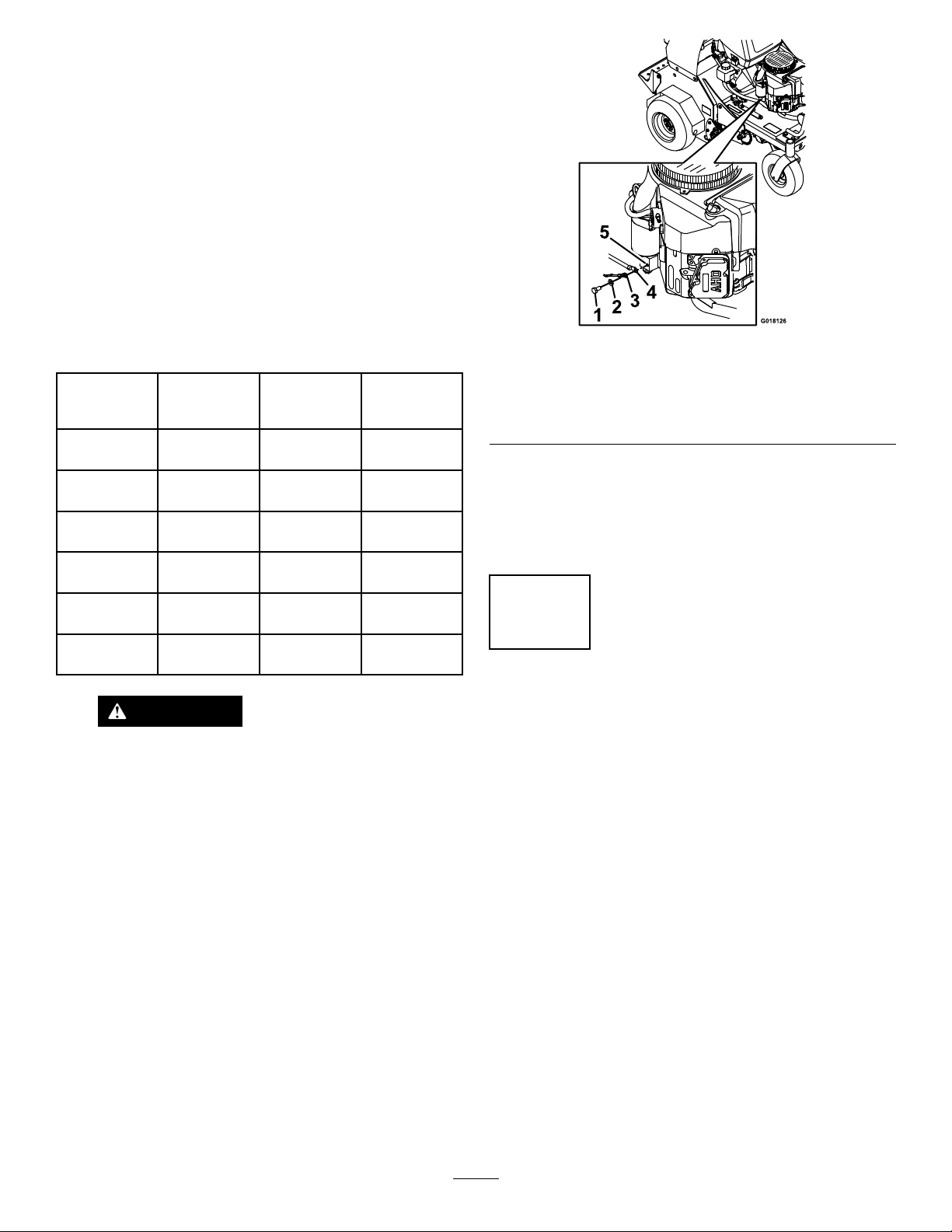
Figure4
1.Screw
2.Washer5.Engine
3.Groundwire
4.Negativebatterycable
Note:Iftimedoesnotpermitchargingthe
batteryorifchargingequipmentisnotavailable,
connectthenegativebatterycablesandrun
thevehiclecontinuouslyfor20to30minutesto
chargethebattery.
3
CheckingFluidLevels
g018126
CAUTION
IftheignitionisintheONpositionthere
ispotentialforsparksandengagement
ofcomponents.Sparkscouldcause
anexplosionormovingpartscould
accidentallyengagecausingpersonal
injury.
BesureignitionswitchisintheOFF
positionbeforechargingthebattery.
4.Ifthepositivecableisalsodisconnected,
connectthepositive(red)cabletothepositive
batteryterminalandslipterminalcoveroverthe
positiveterminal.
5.Removethescrew,washer,andgroundcable
fromtheengine.Connectthenegativebattery
cableasshowninFigure4.
NoPartsRequired
Procedure
Checktheengine-oillevelbeforetheengineisrst
started;refertoCheckingtheEngine-OilLevel(page
18).
Checkthetransmission-oillevelbeforetheengineis
rststarted;refertoCheckingtheTransmission-Oil
Level(page47).
Checktheauxiliaryhydraulic-uidlevelbeforethe
engineisrststarted;refertoCheckingtheAuxiliary
Hydraulic-FluidLevel(page45).
13
4
RemovingtheCylinder
Stop
NoPartsRequired
Procedure
Note:Raisethetinesbeforeremovingthecylinder
stop.Runningtheenginechargesthehydraulic
systemandraisesthetines.
1.Addasmallamountoffueltothefueltank;refer
toAddingFuel(page19).
2.Openthefuel-shutoffvalvebyaligningthelever
forthefuel-shutoffvalvewiththefuelline;refer
toFuel-ShutoffValve(page17).
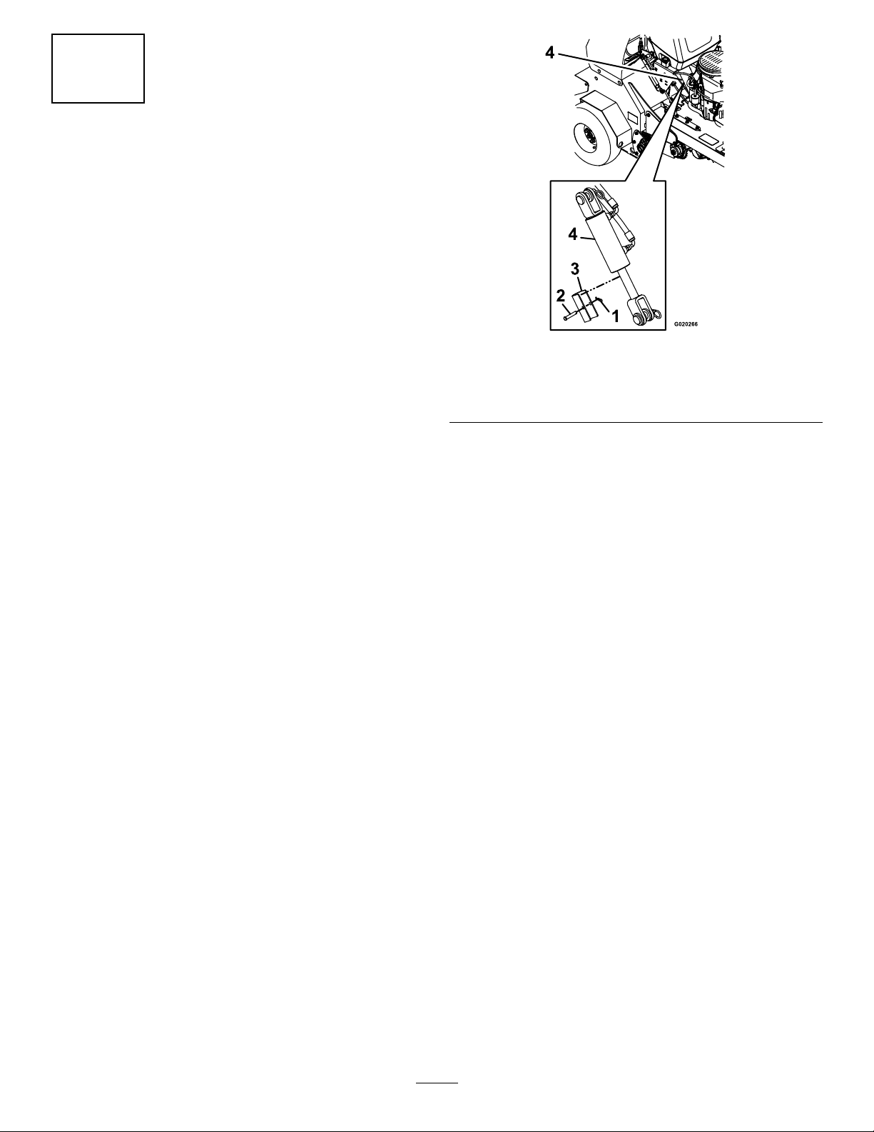
Figure5
1.Hairpin
2.Clevispin4.Cylinder
g020266
3.Cylinderstop
3.Movethemotion-controlleverstotheneutral
positionandengagetheparkingbrake;referto
Traction-ControlLevers(page15).
4.PlacethethrottlemidwaybetweentheSLOWand
FASTpositions;refertoThrottleLever(page16).
5.Pushforwardthechokelevertosetthechoketo
theONposition;refertoChokeLever(page16).
6.TurnthekeyswitchtotheSTARTposition;refer
toIgnitionSwitch(page16).
Note:Releasetheswitchassoonastheengine
starts.
Important:Donotcranktheengine
continuouslyformorethan10secondsat
atime.Iftheenginedoesnotstart,allowa
60-secondcooldownperiodbetweenstarting
attempts.Failuretofollowtheseguidelines
canburnoutthestartermotor.
7.Graduallymovetheleverforthechokeleverto
theOFFpositionastheenginewarmsup.
Note:Allowtheenginetorunanadditional30
seconds
11.Connectthespark-plugwires.
8.TurnthekeyswitchtotheOFFpositiontoshut
offtheengine.
9.Removethekeyandpullthewiresoffthespark
plugs.
Note:Pushthewiresasidesotheydonot
accidentallycontactthesparkplugs.
10.Removeandretainthehairpin,clevispin,and
cylinderstopasshowninFigure5.
14
ProductOverview
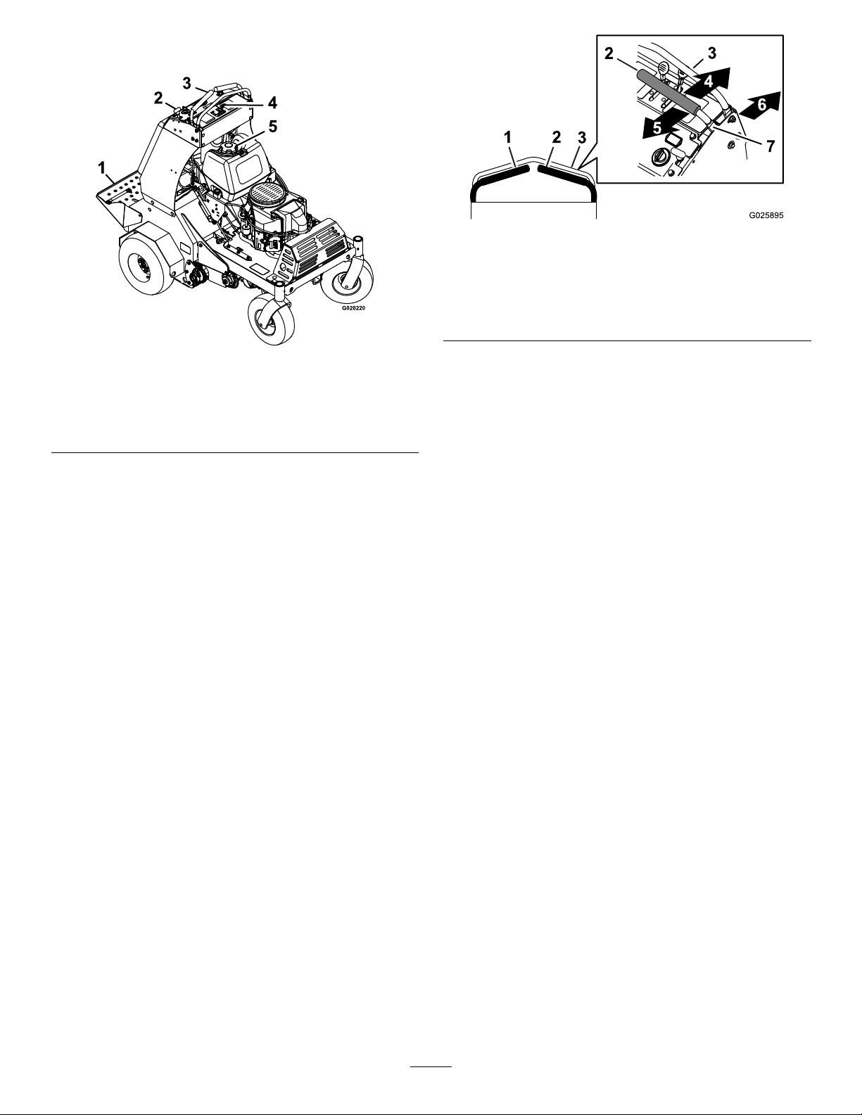
g025895
Figure7
Figure6
1.Platform
2.Parking-brakeknob5.Fuelcap
3.Traction-controllevers
4.Enginecontrols
Controls
Traction-ControlLevers
Thetraction-controlleversarelocatedoneachsideof
thetopconsole,andcontroltheforwardandreverse
motionofthemachine.
Movetheleversforwardorbackwardtocontrolthe
drivewheelonthesamesideforwardorreverse
respectively.Thewheelspeedisproportionaltothe
amounttheleverismoved.
1.Lefttraction-controllever
2.Righttraction-controllever
3.Frontreferencebar
4.Forward
g020220
5.Reverse
6.Frontofthemachine
7.Neutral
Tine-PressureControl
Thetine-pressurecontrolislocatedontheleftsideof
thecontrolconsole(Figure8).
Usethetine-pressurecontroltoadjustthedownward
pressureonthetinesandcoredepth.Rotatethe
controlcounterclockwisetodecreasethepressure
andthelengthoftheaerationplug;rotateclockwise
toincreasepressureandincreasethelengthofthe
aerationplug.
Important:Thetinesrotatewhenthe
traction-controlleversaremovedoutofthe
Neutralposition.
15
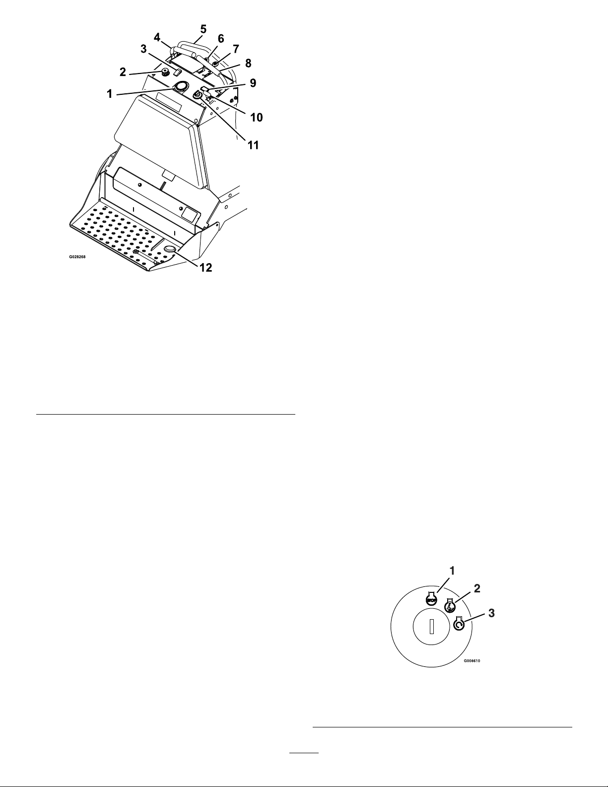
Figure8
1.Tinedownpressuregauge
2.Tinedownpressure
control
3.On/Off-tineground
engagementfootswitch
4.Leftmotion-controllever
5.Frontreferencebar
6.Throttle12.Tinegroundengagement
7.Choke
8.Rightmotion-controllever
9.Hourmeter
10.Parkbrake
11.Ignitionswitch
ChokeLever
Thechokelever(Figure8)islocatedonthecontrol
console(blacklever).
Thechokeleverisusedtoaidinstartingacold
engine.TosetthechoketotheONposition,move
thechokeleverforward.T oreducethechoke,move
thechokeleverbackward.
Note:Pullthechokeleverbackintothedetenttoset
thechoketotheOFFposition.
Note:Donotrunawarmenginewiththechokein
theONposition.
Parking-BrakeHandle
Theparking-brakehandleislocatedonthecontrol
console,totherightoftheignitionswitch(Figure8).
Note:Thebrakehandlesetsaparkingbrakeineach
g028268
footswitch
ofthetransmissions.
Tosetthebrake,pullthehandleoutandslideit
backward.T orelease,pushthehandleforwardinto
thedetent.
Whenparkingonasteepslope,thewheelsmustbe
chockedorblockedinadditiontothebrakebeingset.
Themachinemustbetieddownandbrakesetwhen
transporting.
HourMeter
ThrottleLever
Thethrottlelever(Figure8)islocatedonthecontrol
console(redlever).
Toincreaseenginespeed,movethethrottlelever
forward.T odecreaseenginespeed,movethethrottle
leverbackward.
Note:Movethethrottleleverforwardintothedetent
forfullthrottle.
Thehourmeterislocatedabovetheignitionswitch
(Figure8).
Thehourmeterdisplaysthetotalnumberofhours
thatyouhaverunthemachine.
IgnitionSwitch
Theignitionswitchislocatedontherightsideofthe
controlconsole(Figure8).
Theswitchhas3positions:OFF,ON,andST ART
(Figure9).
g008610
Figure9
1.Off3.Start
2.On
16
On/OffTineGroundEngagement
FootSwitch
Locatedabovethetinedownpressurecontrolonthe
controlconsole.
Toenablethetinesgroundengagement,pushdown
onthetopoftheswitch.T odisablethetinesground
engagement,pushdownontherearoftheswitch.
Tine-PressureGauge
Thetine-pressuregaugeislocatedinthemiddleof
thecontrolconsole(Figure8).
Thetine-pressuregaugetoindicatesthedownward
pressurethemachineexertsonthetineswhen
aerating.
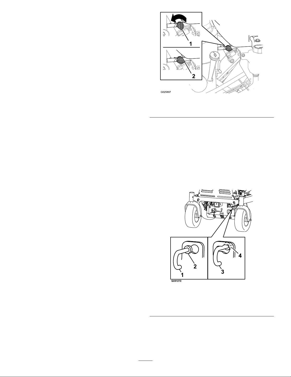
g025897
Figure10
1.Offposition2.Onposition
Tines-ElevationSwitch
Keepyouhandsandfeetawayfromthetines.
Makesurethatthetinesareaisclearofany
obstructionsbeforeloweringit.
Thetine-elevationswitchislocatedontheoperator
platform(Figure8).
Tolowerthetinesintotheground,standonthe
tine-elevationswitch.T oraisethetines,removeyour
footfromtheswitch.
Fuel-ShutoffValve
Thefuel-shutoffvalveislocatedbehindtheengine
andunderthefueltank(Figure10).
Usethefuel-shutoffvalvetoshutoffthefuelwhen
themachinewillnotbeusedforafewdays,when
transportingthemachinetoandfromthejobsite,or
whenthemachineisparkedinsideabuilding.
Toopenforfuel-shutoffvalve,rotatethehandleofthe
fuel-shutoffvalveuntilitisalignedwiththefuelline.
Toclosethefuel-shutoffvalve,rotatethehandle90°
tothefuelline.
DriveWheelReleaseValves
Thedrivewheelreleasevalvesarelocatedontheleft
andrightsidesunderneaththefrontoftheunit.
Note:Duringnormaloperatingconditions,the
washerontheleverispositionedinsidetheslots.
Ifyouneedtopushthemachinebyhand,makesure
thatthevalvesareinthe“released”position(Figure
11).
Figure11
1.Leverpositiontopushthe
machine
2.Washeroutsideofslot
Toreleasethedrivewheels,movethelevertothe
largeropeningoftheslot,pullitoutuntilthewasher
isoutsidetheframe,thenmovetheleverbacktothe
narrowportionoftheslot.Repeatthisoneachside
ofthemachine.
17
3.Leverpositionfor
operatingthemachine
4.Washerinsideslot
g031272
Disengagetheparkingbraketoallowyoutopushthe
machinebyhand.
Operation
Important:Donottowthemachine.
Toresetthedrivesystembacktotheoperating
position,movethelevertothelargeropeningofthe
slot,pushinwarduntilthewasherisinsidetheframe,
thenmovetheleverbacktothenarrowportionofthe
slot.Repeatthisoneachsideofthemachine.
Specications
Height
Length
Width
AerationWidth
Coringrange5to13cm(2to5inches)
Weight
132cm(52inches)
162cm(64inches)
121cm(48inches)
76cm(30inches)
460kg(1,015lb)
Note:Determinetheleftandrightsidesofthe
machinefromthenormaloperatingposition.
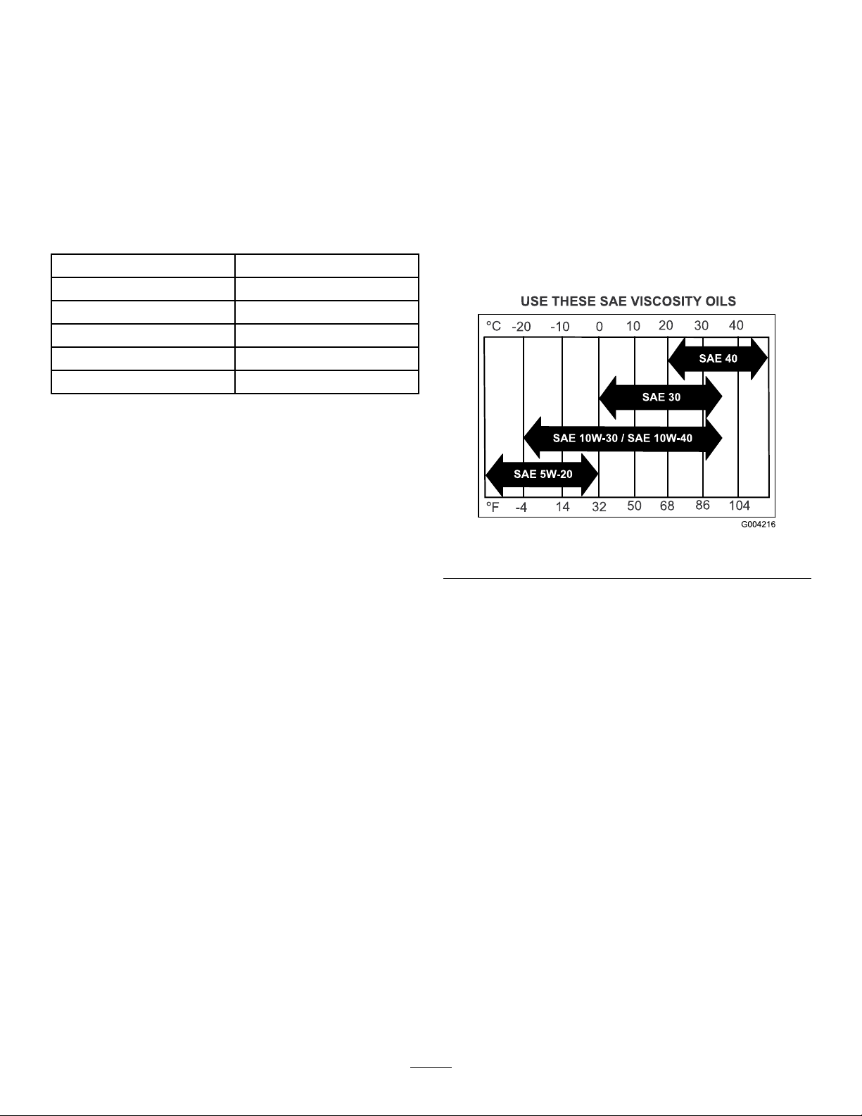
CheckingtheEngine-Oil
Level
ServiceInterval:Beforeeachuseordaily
OilType:Detergentoil(APIserviceSJorhigher)
Oilviscosity:Refertothetablebelow.
Figure12
Important:Donotoperatetheenginewiththeoil
levelbelowtheLow(orAdd)markonthedipstick,
orovertheFullmark.
1.TurnthekeyintheignitionswitchtotheOFF
position,removethekey,andwaitforallmoving
partstostopbeforeleavingtheoperating
position
2.Allowtheenginetocool.
3.Checktheengine-oillevelasshowninFigure
13.
g004216
18

AddingFuel
Fueltankcapacity:18.9L(5USGallons)
•Forbestresults,useonlyclean,fresh(lessthan
30daysold),unleadedgasolinewithanoctane
ratingof87orhigher((R+M)/2ratingmethod).
g025899
•ETHANOL:Gasolinewithupto10%ethanol
(gasohol)or15%MTBE(methyltertiarybutyl
ether)byvolumeisacceptable.Ethanoland
MTBEarenotthesame.Gasolinewith15%
ethanol(E15)byvolumeisnotapprovedforuse.
Neverusegasolinethatcontainsmorethan10%
ethanolbyvolume,suchasE15(contains15%
ethanol),E20(contains20%ethanol),orE85
(containsupto85%ethanol).Usingunapproved
gasolinemaycauseperformanceproblemsand/or
enginedamagewhichmaynotbecoveredunder
warranty.
•Donotusegasolinecontainingmethanol.
•Donotstorefueleitherinthefueltankorfuel
containersoverthewinterunlessafuelstabilizer
isused.
Figure13
4.Iftheoillevelislow,wipeofftheareaaround
theoilllcap,removecapandaddthespecied
oiluntiltheoillevelisattheFullmarkonthe
dipstick.
•Donotaddoiltogasoline
DANGER
Incertainconditions,fuelisextremely
ammableandhighlyexplosive.Areor
explosionfromfuelcanburnyouandothers
andcandamageproperty.
•Fillthefueltankoutdoors,inanopenarea,
andwhentheengineiscold.Wipeupany
fuelthatspills.
•Donotllthefueltankcompletelyfull.
Addfueltothefueltankuntilthelevelis6
to13mm(1/4to1/2inch)belowthebottom
ofthellerneck.Thisemptyspaceinthe
tankallowsthefueltoexpand.
•Neversmokewhenhandlingfuel,andstay
g025898
awayfromanopenameorwhereaspark
mayignitethefuelfumes.
•Storefuelinanapprovedfuelcontainer
andkeepitoutofthereachofchildren.
•Neverbuymorethana30-daysupplyof
fuel.
Note:Donotoverlltheenginewithoil.
19

DANGER
Incertainconditionsduringfueling,static
electricitycanbereleasedcausingaspark
whichcanignitethefuelvapors.Areor
explosionfromfuelcanburnyouandothers
andcandamageproperty.
Addthecorrectamountoffuelstabilizer/conditioner
tothefuel.
Note:Afuelstabilizer/conditionerismost
effectivewhenmixedwithfreshfuel.T ominimize
thechanceofvarnishdepositsinthefuelsystem,
usefuelstabilizeratalltimes.
•Alwaysplacefuelcontainersontheground
awayfromyourvehiclebeforelling.
•Donotllfuelcontainersinsideavehicle
oronatruckortrailerbedbecauseinterior
carpetsorplastictruckbedlinersmay
insulatethecontainerandslowthelossof
anystaticcharge.
•Whenpractical,removefuel-powered
equipmentfromthetruckortrailerand
refueltheequipmentwithitswheelsonthe
ground.
•Ifthisisnotpossible,thenrefuelsuch
equipmentonatruckortrailerfroma
portablecontainer,ratherthanfroma
fuel-dispensernozzle.
•Ifafuel-dispensernozzlemustbeused,
keepthenozzleincontactwiththerimof
thefueltankorcontaineropeningatall
timesuntilfuelingiscomplete.
WARNING
Fuelisharmfulorfatalifswallowed.
Long-termexposuretovaporscancause
seriousinjuryandillness.
FuelingtheMachine
1.Cleanaroundthefuel-tankcap.
2.Removethecapfromthetank.
3.Fillthefueltankwithunleadedfueltowithin6to
13mm(1/4to1/2inch)fromthetopofthetank.
Donotllintothellerneck.
Important:Donotllthetankmorethan
6mm(1/4inch)fromthetopofthetank
becausethefuelmusthaveroomtoexpand.
4.Installthefuel-tankcapandwipeupanyspilled
fuel.
LubricatingtheChains
CheckingtheConditionofthe
Sprockets
ServiceInterval:Beforeeachuseordaily
1.TurnthekeyintheignitionswitchtotheOFF
position,engagetheparkingbrake,waitforall
movingpartstostop,andremovekey.
2.Inspectsprocketsforwearandreplaceas
required(Figure14).
•Avoidprolongedbreathingofvapors.
•Keepfaceawayfromnozzleandfueltank
orconditionerbottleopening.
•Avoidcontactwithskin;washoffspillage
withsoapandwater.
UsingStabilizer/Conditioner
Useafuelstabilizer/conditionerinthemachineto
providethefollowingbenets:
•Keepsfuelfreshduringstorageof90daysorless.
Forlongerstorageitisrecommendedthatthefuel
tankbedrained.
•Cleanstheenginewhileitruns
•Eliminatesgum-likevarnishbuildupinthefuel
system,whichcauseshardstarting
Important:Donotusefueladditives
containingmethanolorethanol.
20

1.TurnthekeyintheignitionswitchtotheOFF
position,engagetheparkingbrake,waitforall
movingpartstostop,andremovekey.
2.Raisethemachineandsupportitwithjack
standswitha460kg(1,015lb)capacity.
CAUTION
Raisingthemachineforservice
ormaintenancerelyingsolelyon
mechanicalorhydraulicjackscouldbe
dangerous.Themechanicalorhydraulic
jacksmaynotbeenoughsupportormay
malfunctionallowingthemachinetofall,
whichcouldcauseinjury .
Donotrelysolelyonmechanical
orhydraulicjacksforsupport.Use
adequatejackstandsorequivalent
support.
3.TurnthekeyintheignitionswitchtotheON
position,andmovethrottlelevelaheadto1/2
throttleposition.
Figure14
1.Sprockets2.Chains
CheckingtheConditionofthe
Chains
ServiceInterval:Beforeeachuseordaily
1.TurnthekeyintheignitionswitchtotheOFF
position,engagetheparkingbrake,waitforall
movingpartstostop,andremovekey.
2.Checkthechaintension(Figure14)atboth
sidesofthemachine.
Note:Thechainsshouldmoveupanddown6
to12mm(1/4to1/2inch).
3.Ifchainspoporsnap;refertoAdjustingthe
JackshaftDriveChainTension(page40),
AdjustingtheTensionontheDrive-WheelChain
(page41),orAdjustingtheTine-DriveChain
(page50).
g025984
WARNING
Enginemustberunninganddrivewheels
mustbeturningsoadjustmentscanbe
performed.Contactwithmovingpartsor
hotsurfacesmaycausepersonalinjury.
Keepngers,hands,andclothingclear
ofrotatingcomponentsandhotsurfaces.
4.Disengagetheparkingbrake.
5.Withtheenginerunning,slowlymovethe
traction-controlleversforwardandlubricateall6
chains(Figure14).
6.Checktheconditionandtensionofthechains;
refertoCheckingtheConditionoftheChains
(page21).
LubricatingtheChains
ServiceInterval:Beforeeachuseordaily
Important:Donotlubricatechainswith
penetratingoilorsolvents.Useoilorchain
lubricant.
21

Checkingthe
Safety-InterlockSystem
ServiceInterval:Beforeeachuseordaily
CAUTION
Ifsafetyinterlockswitchesaredisconnected
ordamagedthemachinecouldoperate
unexpectedlycausingpersonalinjury.
•Donottamperwiththeinterlockswitches.
•Checktheoperationoftheinterlock
switchesdailyandreplaceanydamaged
switchesbeforeoperatingthemachine.
UnderstandingtheSafety-InterlockSystem
Thesafetyinterlocksystemisdesignedtopreventthe
enginefromstartingunlessthetraction-controllevers
areintheneutralposition.
CheckingtheSafety-InterlockSystem
1.Disconnectthespark-plugwires;referto
RemovingtheSparkPlug(page35).
OperatingtheMachine
OpeningtheFuel-ShutoffValve
Rotatetheleverofthefuel-shutoffvalvetoalignthe
leverwiththefuelline.
g025897
Figure15
1.Offposition2.Onposition
2.Whileonlevelground,blockthewheelsofthe
machinetopreventunintendedmovement.
3.Disengagetheparkingbrake;referto
Parking-BrakeHandle(page16).
4.Withthetraction-controlleversintheneutral
positionturnthekeytothestartposition—the
startermustnotcrank;refertoTraction-Control
Levers(page15)andIgnitionSwitch(page16).
Note:Ifthemachinedoesnotpassthistest,donot
operate.ContactyourauthorizedT oroServiceDealer.
Important:Itisessentialthattheoperator
safetymechanismsbeconnectedandinproper
operatingconditionpriortouseforaerating.
CheckingforLoose
Hardware
ServiceInterval:Beforeeachuseordaily
1.TurnthekeyintheignitionswitchtotheOFF
position,engagetheparkingbrake,waitforall
movingpartstostop,andremovekey.
2.Visuallyinspectmachineforanyloosehardware
oranyotherpossibleproblem.
Note:Tightenallloosehardwareorrepairthe
problembeforeoperatingthemachine.
22

StartingtheEngine
1.Movethetraction-controlleverstotheNEUTRAL
positionandengagetheparkingbrake;refer
toTraction-ControlLevers(page15)and
Parking-BrakeHandle(page16).
Note:Tostarttheengine,theparkingbrake
mustbeengaged.(Itisnotnecessaryforthe
operatortobeontheplatform.)
2.Placethethrottlelevermidwaybetweenthe
SLOWandFASTpositions;refertoThrottleLever
(page16).
3.Iftheengineiscold,pushthechokelever
forwardtotheONposition;refertoChokeLever
(page16).
Note:Iftheengineiswarm,pullthechoke
levertotheOFFposition.
4.TurnthekeyintheignitionswitchtotheSTART
position;refertoIgnitionSwitch(page16).
Note:Releasethekeyintheignitionswitchas
soonastheenginestarts.
3.Standontheswitchandmovethetraction-control
leversforwardtoaerate(Figure16);referto
Traction-ControlLevers(page15).
4.Adjustthethrottlefortheworkingconditions;
refertoThrottleLever(page16).
AdjustingtheTineDownPressure
Important:Keepthedrivetiresonthegroundat
alltimes.
Adjusttheplugdepthbyrotatingthetinepressure
controlasfollows:
Note:Firsttimeuse:setthetinepressurecontrol
sothatthetine-pressuregauge(Figure17)indicates
24bar(350psi).
Important:Donotcranktheengine
continuouslyformorethantensecondsata
time.Iftheenginedoesnotstart,allowa60
secondcool-downperiodbetweenstarting
attempts.Failuretofollowtheseguidelines
canburnoutthestartermotor
5.IfthechokeleverisintheONposition,gradually
movethelevertowardtheOFFpositionasthe
enginewarmsup.
LoweringtheTines
1.SetthrottlelevertotheMIDWAYposition;referto
ThrottleLever(page16).
2.Steponthetine-elevationswitchtolowerthe
tines(Figure16).
Figure17
1.Tine-pressurecontrol3.Decreasepressure
2.Tine-pressuregauge
(shorterplug)
4.Increasepressure(longer
plug)
•Rotatethetine-pressurecontrol
counterclockwise(Figure17)todecrease
thedownwardpressureinordertoremovea
shorterplug.
•Rotatethetine-pressurecontrolclockwise(Figure
17)toincreasedownwardpressureinorderto
removealongerplug.
Note:Idealplugdepthis7.6to10cm(3to4inches).
Rotatethetine-pressurecontroltoadapttothesoil
conditions.
g025901
1.Tine-elevationswitch
Figure16
RaisingtheTines
Toraisethetines,removeyourfootfromthe
tine-elevationswitch(Figure16).
g025900
Important:Thetinesrotatewhenthe
traction-controlleverismovedoutoftheNEUTRAL
position.
23

StoppingtheEngine
1.Movethetraction-controlleverstotheNEUTRAL
positionandbringthemachinetoafullstop;
refertoTraction-ControlLevers(page15).
2.Liftyourfootoffofthetinegroundengagement
footswitchcontroltoraisethetines;referto
RaisingtheTines(page23).
3.Placethethrottleinthemidwaybetweenthe
SLOWandFASTpositions;refertoThrottleLever
(page16).
4.Allowtheenginetorunforaminimumof15
seconds,thenturnthekeyintheignitionswitch
totheOFFpositiontoshutofftheengine;refer
toIgnitionSwitch(page16).
5.Engagetheparkingbrake;refertoParking-Brake
Handle(page16).
6.Removethekeytopreventchildrenorother
unauthorizedpersonsfromstartingtheengine.
7.Closethefuel-shutoffvalvewhenthemachine
willnotbeinuseforafewdays,when
transporting,orwhenthemachineisparked
insideabuilding;refertoFuel-ShutoffValve
(page17).
Figure18
1.Lefttraction-controllever
2.Righttraction-controllever6.Neutral
3.Frontreferencebar
4.Frontofthemachine
5.Forward
7.Reverse
DrivingForward
1.Makesurethatthetraction-controlleversarein
theNEUTRALposition.
2.Disengagetheparkingbrake.
3.T omoveforwardinastraightline,moveboth
leversforwardwithequalpressure.
g020241
DrivingtheMachine
CAUTION
Machinecanspinveryrapidlybypositioning
1levertoomuchaheadoftheother.Operator
maylosecontrolofthemachine,whichmay
causedamagetothemachineorinjury .
•Usecautionwhenmakingturns.
•Slowthemachinedownbeforemaking
sharpturns.
Important:Tobeginmovement(forwardor
backward),thebrakelevermustbedisengaged
(pushedforward)beforethetraction-control
leverscanbemoved.
g016672
Figure19
Toturnleftorright,pullthetraction-controllever
backtowardneutralinthedesiredturndirection.
Thetinescanbeinthedownpositionwhen
makinggradualturns.
Tomakezeroturns,liftyourfootoffofthetine
engagementfootswitchcontroltoraisethe
tines.Theheadraisesin1second.
Important:Donotmakeazeroturnwhen
thetinesaredownasturftearingwillresult.
24

Themachinemovesfasterthefartheryoumove
thetraction-controlleversfromtheneutral
position.
4.T ostop,positionbothtraction-controlleversin
theneutraloperateposition.
DrivinginReverse
1.Movethetraction-controlleverstothe
NEUTRAL/OPERATEposition.
2.T omoverearwardinastraightline,slowlymove
bothleversrearwardwithequalpressure.
CAUTION
Thismachinedoesnothaveproperturn
signals,lights,reectivemarkings,ora
slowmovingvehicleemblem.Drivingona
streetorroadwaywithoutsuchequipment
isdangerousandcanleadtoaccidents
causingpersonalinjury.Drivingonastreetor
roadwaywithoutsuchequipmentmayalsobe
aviolationofStatelawsandtheoperatormay
besubjecttotrafcticketsand/ornes.
Donotdriveamachineonapublicstreetor
roadway.
Totransportthemachine:
1.Raisethetinesofthemachinebeforedriving
ontothetrailerortruck.
2.Ifusingatrailer,connectittothetowingvehicle
andconnectthesafetychains.
3.Ifapplicable,connectthetrailerbrakes.
4.Loadthemachineontothetrailerortruck.
Figure20
Toturnleftorright,releasepressureonthe
traction-controllevertowardthedesiredturn
direction.
Tomakezeroturns,liftyourfootoffofthe
tine-elevationswitchtoraisethetines.Thehead
raisesin1second.
Important:Donotmakeazeroturnwhen
thetinesareinthedownposition.
3.T ostop,positionbothtraction-controlleversin
theNEUTRAL/OPERATEposition.
TransportingtheMachine
Machineweight:460kg(1,015lb)
Useaheavy-dutytrailerortrucktotransportthe
machine.Ensurethatthetrailerortruckhasall
thenecessarybrakes,lighting,andmarkingas
requiredbylaw.Pleasecarefullyreadallthesafety
instructions.
5.Shutofftheengine,removethekey,setthe
g016673
brake,andclosethefuelvalve.
6.Engagetheparkingbrakeandblockthetires.
7.Usethetie-downpointsonthemachineto
securelybindthemachinetothetrailerortruck
withstraps,chains,cable,orropes(Figure21).
Note:Refertoyourlocalordinancesforspecic
trailerandtie-downregulations.
g025949
Figure21
1.Tie-downpoints
25

LoadingtheMachine
Useextremecautionwhenloadingunitsontotrailers
ortrucks.Use1full-widthrampthatiswideenoughto
extendbeyondthereartiresisrecommendedinstead
ofindividualrampsforeachsideofthemachine
(Figure22).Theplatform,whendownandlockedinto
position,mustextendbackbetweentherearwheels
andservesasastopfortippingbackward.Havinga
full-widthrampprovidesasurfacefortheplatformto
contactifthemachinestartstotipbackward.Withthe
platformup,afull-widthrampprovidesasurfaceto
walkonbehindthemachine.
Therampshouldbelongenoughsothattheangles
donotexceed15degrees(Figure22).Asteeper
anglemaycausetinecomponentstogetcaught,as
themachinemovesfromramptotrailerortruck.A
steeperanglemayalsocausethemachinetotip
backward.Ifloadingonornearaslope,positionthe
trailerortrucksoitisonthedownsideoftheslope
andtherampextendsuptheslope.Thisminimizes
therampangle.Thetrailerortruckshouldbeaslevel
aspossible.
Figure22
1.Trailer3.Notgreaterthan15
2.Full-widthramp
degrees
4.Full-widthramp(sideview)
g000951
WARNING
Loadingthemachineontoatrailerortruck
increasesthepossibilityofbackwardtip-over,
andcouldcauseseriousinjuryordeath.
•Useextremecautionwhenoperatinga
machineonaramp.
•Useonlyasingle,full-widthramp;donot
useindividualrampsforeachsideofthe
machine.
•Ifindividualrampsmustbeused,use
enoughrampstocreateanunbrokenramp
surfacewiderthanthemachine.
•Donotexceeda15-degreeanglebetween
rampandground,orbetweenaramp,a
trailer,oratruck.
•Avoidsuddenaccelerationwhiledriving
machineuparamptoavoidtipping
backward.
•Avoidsuddendecelerationwhilebacking
machinedownaramptoavoidtipping
backward.
Theoperatorshoulddetermineifitisbesttohave
theplatformupordownwhenloading,dependingon
conditions.Ifitisnotpossibletouse1full-widthramp,
useenoughindividualrampstosimulateafull-width,
continuousramp.
Avoidsuddenaccelerationwhendrivinguparamp
andsuddendecelerationwhenbackingdowna
ramp.Bothmaneuverscancausethemachinetotip
backward.
26

Maintenance
WARNING
Whileyouaremaintainingoradjustingthe
machine,someonecouldstarttheengine.
Accidentallystartingtheenginecould
seriouslyinjureyouorotherbystanders.
Removethekeyfromtheignitionswitch,
engageparkingbrake,andpullthewire(s)
offthesparkplug(s)beforeyoudoany
maintenance.Alsopushthewire(s)asideso
itdoesnotaccidentallycontactthespark
plug(s).
RecommendedMaintenanceSchedule(s)
MaintenanceService
Interval
Aftertherst100hours
Beforeeachuseordaily
MaintenanceProcedure
•Changetheauxiliaryhydraulicreservoirlteranduid.
•Changethetransmissionlters.
•Fillthetransmissionwithoilwhenchangingthelter.
•Checktheengine-oillevel.
•Checktheconditionofthesprockets.
•Checktheconditionandtensionofthechains.
•Lubricatethechains.
•Checkthesafetyinterlocksystem.
•Checkforloosehardware.
•Checkthetines.
•Cleantheengineandtheexhaustsystemarea.
•Cleanthegrassanddebrisbuildupfromthemachine.
WARNING
Theenginecanbecomeveryhot.Touchinga
hotenginecancausesevereburns.
Allowtheenginetocoolcompletelybefore
serviceormakingrepairsaroundtheengine
area.
Every25hours
Every50hours
Every80hours
Every100hours
Every160hours
Every200hours
•Greasethejackshaftbearings.
•Greasethewheelbearings.
•Greasethetineshaftbearings.
•Greasethetineassemblyidlers.
•Greasethecontrolpivots.
•Checksparkarrester(ifequipped).
•Checkthepressureinthetires.
•Checktheconditionandtensionofthebelts.
•Checktheauxiliaryhydraulic-uidlevel.
•Checkthehydraulictransmissionoil-level.
•Removetheengineshroudsandcleanthecoolingns.
•Check,cleanandgapthesparkplug.
•Checkthebattery.
•Checkthesparkplugs.
•Checkthepaperair-cleanerelement(moreoftenundersevereconditions).
•Changetheengine-oillter.
27

MaintenanceService
Every250hours
Every500hours
Interval
MaintenanceProcedure
•Replacetheprimaryaircleanerelement—checksecondaryaircleanerelement;
replaceifdirty.(Mayneedmoreoftenundersevereconditions.SeetheEngine
Owner’sManualforadditionalinformation.)
•Cleanthefoamair-cleanerelement(moreoftenundersevereconditions).
•Changetheauxiliaryhydraulicreservoirlteranduid.
•Changethetransmissionlters.
•Fillthetransmissionwithoilwhenchangingthelter.
•Replacethesecondaryaircleanerelement.(Mayneedmoreoftenundersevere
conditions.SeetheEngineOwner’sManualforadditionalinformation.)
•Replacethepaperair-cleanerelement(moreoftenundersevereconditions).
Every800hours
Yearly
Yearlyorbeforestorage
•Replacethefuellter.
•Greasethefrontcasterpivots.
•Greasethebeltidlerpivot.
•Greasethecasterpivotsandhubs.
•Lubricatethecasterwheelhubs.
•Lubricatethecasterwheelhubs.
•Checkthetorqueofthewheelhubnuts.
•Checkthetorqueonthewheellugnuts.
•Checkthetorqueofthetransmissionoutputshaftnut.
•T ouchupchippedpaint
Pre-Maintenance
Procedures
CAUTION
Raisingthemachineforserviceor
maintenancerelyingsolelyonmechanical
orhydraulicjackscouldbedangerous.The
mechanicalorhydraulicjacksmaynotbe
enoughsupportormaymalfunctionallowing
themachinetofall,whichcouldcauseinjury.
AccessingtheConsole
Compartment
RemovingtheConsolePad
1.Loosenthe4anged-headboltsthatsecurethe
padtotheleftandrightconsolepanels(Figure
23).
Donotrelysolelyonmechanicalorhydraulic
jacksforsupport.Useadequatejackstands
orequivalentsupport.
PreparingfortheMachine
forMaintenance
Performthefollowingbeforeservicing,cleaning,or
makinganyadjustmentstothemachine.
1.Movethemachinetoalevelsurface.
2.TurnthekeyintheignitionswitchtotheOFF
position,engagetheparkingbrake,waitforall
movingpartstostop.
3.Removethekeyfromthekeyswitch.
Figure23
1.Keyholeslot(console
panel)
2.Fanged-headbolt
2.Liftuptheconsolepad(Figure23)approximately
13mm(1/2inch).
3.Pulltheconsolepadstraightbackandremove
thepadfromthemachine(Figure23).
28
g025880
3.Pad

InstallingtheConsolePad
1.Alignthe4anged-headboltsattheforward
faceoftheconsolepadtothe4keyholeslotsin
theframeoftheconsole(Figure23).
Lubrication
LubricatingtheGrease
2.Movethepadforwarduntilthepadisushto
theconsoleframe(Figure23).
3.Movethepaddownuntiltheanged-headbolts
areseatedinthekeyholeslots(Figure23).
4.T orquetheanged-headboltsto1978to2542
N-cm(175to225lb-in).
Fittings
Greasetype:NationalLubricatingGreaseInstitute
(NGLI)grade#2multi-purposegungrease.
Note:Refertothelubricationchartforservice
intervals.
LubricationChart
Fitting
Locations
1.FrontCaster
Pivots
2.Jackshaft
Bearings
3.Wheel
Bearings
4.TineShaft
Bearings
5.Tine
AssemblyIdlers
6.Control
Pivots
7.BeltIdler
Pivot
8.FrontCaster
Hubs
Initial
Pumps
*0
1825hours
1225hours
1425hours
1225hours
1450hours
11Y early
*0
Numberof
Places
Service
Interval
2Yearly
2Yearly
Figure24
1.TurnthekeyintheignitionswitchtotheOFF
position,engagetheparkingbrake,waitforall
movingpartstostop,andremovethekey .
2.Wipecleanthegreasettingswitharag(Figure
24).
29
g020222

3.Connectagreaseguntothetting(Figure24).
RemovingtheCaster-WheelAssembly
4.Pumpgreaseintothettingsuntilgreasebegins
tooozeoutofthebearings.
5.Wipeupanyexcessgrease.
LubricatingtheCasters
Greasetype:NationalLubricatingGreaseInstitute
(NGLI)grade#2multi-purposegungrease.
GreasingtheCasterPivots
ServiceInterval:Yearly
1.Removecapandhexplugfromthetopofthe
casterpivot(Figure25).
1.TurnthekeyintheignitionswitchtotheOFF
position,engagetheparkingbrake,waitforall
movingpartstostop,andremovekey.
2.Liftthefrontofthemachineandsupportitwith
jackstands.
3.Removethewheelnutandbolt,andremovethe
caster-wheelassemblyfromthefork(Figure26).
g025953
Figure26
1.Wheelbolt3.Wheelnut
2.Caster-wheelassembly
Figure25
1.Hexplug
2.Greasetting4.Cap
2.Threadgreasettinginhole(Figure25).
3.Pumpgreaseintothettinguntilgreaseoozes
outaroundtopbearing(Figure25).
4.Removegreasettingandinstalltheplugthat
youremovedin1(Figure25).
5.Installthecapthatyouremovedinstep1(Figure
25).
3.Casterpivot
DisassemblingtheCaster-WheelHuband
GreasingtheBearings
ServiceInterval:Yearly
Important:Usenewbearingsealswhen
lubricatingthecaster-wheelhubs.
Important:Topreventsealandbearingdamage,
checkthebearingadjustmentoften.Spinthe
g025955
castertire.Thetireshouldnotspinfreely(more
than1or2revolutions)orhaveanysideplay.If
thewheelspinsfreely,adjusttorqueonspacer
nutuntilthereisaslightamountofdrag.Reapply
thread-lockingadhesive.
Greasetype:NationalLubricatingGreaseInstitute
(NGLI)grade#2multi-purposegungrease.
1.Removethe2sealguardsfromthewheelhub
(Figure27).
6.Repeatsteps1through5totheothercaster.
LubricatingtheCaster-Hubs
Bearings
ServiceInterval:Yearly
30

Figure27
1.Axle(spacernutstill
assembled)
2.Hub5.Bearingseal
3.Bearing
4.Spacernut
6.Sealguard
2.Remove1ofthespacernutsfromtheaxle
assemblyinthecasterwheel(Figure27).
Note:Notethatthread-lockingadhesivehas
beenappliedtolockthespacernutstotheaxle
(Figure27).
3.Removetheaxle(withtheotherspacernutstill
assembledtoit)fromthecaster-wheelassembly
(Figure27).
4.Pryoutbothofthebearingseals(Figure27).
Note:Discardtheoldseals.
5.Removebothofthebearingsandinspecteach
ofthemforwearordamage(Figure27).
Note:Replacethebearingifitiswornor
damaged.
6.Packthe2bearingswiththespeciedgrease.
AssemblingtheCaster-WheelHub
1.Install1bearingintothehubofthewheel(Figure
27).
2.Installthebearingsealintothehubatthe
bearing(Figure27).
3.Ifyouremoved(orbrokeloose)bothofthe
spacernutsfromtheaxleassembly,perform
thefollowing:
A.Cleanthethreadsoftheaxleandspacer
nut.
B.Applythread-lockingadhesivetothe
threadsat1endoftheaxle.
C.Threadtheaxlenut,withthewrenchats
facingoutward,ontotheendoftheaxlethat
ispreparedwiththread-lockingcompound
(Figure27).
mm(1/8inch)fromtheoutersurfaceofthe
spacernuttotheendoftheaxleinsidethe
nut.
4.Inserttheassemblednutandaxleintothewheel
atthesideofthewheelwiththenewsealand
bearing(Figure27).
5.Withtheopenendofthewheelfacingup,llthe
areainsidewheelcavity(aroundtheaxle)with
thespeciedgrease.
g025954
6.Installtheotherbearingandnewsealintothe
wheel(Figure27).
7.Applythread-lockingadhesivetothe2ndspacer
nutandthreadontotheaxlewiththewrench
atsfacingoutward.
8.T orquethespacernutto8to9N∙m(75to80
in-lb),loosen,thenre-torqueto2to3N∙m(20
to25in-lb).
Note:Makesureaxledoesnotextend
beyondeithernut.
9.Installthesealguardsoverthewheelhub
(Figure27).
InstallingtheCaster-WheelAssembly
1.Aligntheholeintheaxleofthecaster-wheel
assemblybetweentheholesintheforkofthe
caster(Figure26).
2.Securethetotheforkwiththewheelnutand
bolt(Figure26)thatyouremovedinstep3of
RemovingtheCaster-WheelAssembly(page
30).
3.T orquethewheelnutto91to113N∙m(67to
83ft-lb).
Note:Donotthreadspacernutallofthe
wayontotheaxle.Leaveapproximately3
31

EngineMaintenance
5.Carefullypullthefoamelementoffthepaper
element(Figure28).
ServicingtheAirCleaner
ServiceInterval:Every250hours—Replacethe
primaryaircleanerelement—
checksecondaryaircleaner
element;replaceifdirty.(Mayneed
moreoftenundersevereconditions.
SeetheEngineOwner’sManualfor
additionalinformation.)
Every500hours
Inspectthefoamandpaperelements,andreplace
themiftheyaredamagedorexcessivelydirty .
Important:Donotapplyoiltothefoamorpaper
element.
RemovingtheFoamandPaper
Elements
1.Shutofftheengine,engagetheparkingbrake,
removethekey,andwaitforallmovingpartsto
stopbeforeleavingtheoperatingposition.
2.Cleanaroundtheaircleanertopreventdirtfrom
gettingintotheengineandcausingdamage
(Figure28).
ServicingtheFoamAir-Cleaner
Element
ServiceInterval:Every250hours(moreoftenunder
severeconditions).
1.Inspecttheelementfortears,anoilylm,or
damaged(Figure28).
Important:Replacethefoamelementifit
iswornordamaged.
2.Washthefoamelementinliquidsoapand
warmwater.Whentheelementisclean,rinse
itthoroughly.
3.Drytheelementbysqueezingitinacleancloth.
ServicingthePaperAir-Cleaner
Element
ServiceInterval:Every200hours—Checkthepaper
air-cleanerelement(moreoften
undersevereconditions).
Every500hours—Replacethepaperair-cleaner
element(moreoftenundersevereconditions).
Important:Donotwashthepaperair-cleaner
element.
1.Inspecttheelementfortears,anoilylm,or
damagetotherubberseal(Figure28).
Figure28
1.Cover
2.Hoseclamp4.Foamelement
3.Rotatethecoverknobs1/4turncounterclockwise
andremovetheair-cleanercover(Figure28).
4.Rotatethethumbscrewofthehoseclamp
counterclockwiseuntilyoucanseparatethe
air-cleanerassemblyfromtheinletduct(Figure
28).
3.Paperelement
Note:Replacethepaperelementifitis
damaged.
2.Cleanthepaperelementbygentlytappingitto
removedustanddebris.
Note:Iftheelementisverydirty ,replacethe
air-cleanerelement.
Note:Donotusepressurizedairtocleanthe
paperelement.
InstallingtheFoamandPaper
g012352
Elements
Important:Topreventenginedamage,always
operatetheenginewiththecompletefoamand
paperair-cleanerassemblyinstalled.
1.Carefullyslidethefoamelementontothepaper
air-cleanerelement(Figure28).
2.Aligntheair-cleanerassemblyontotheinletduct
andsecureitwiththehoseclamp(Figure28).
3.Aligntheair-cleanercoverontoenginecover
andsecurethecoverbyrotatingthecoverknobs
1/4tunclockwise(Figure28).
32

ServicingtheEngineOil
OilType:Detergentoil(APIserviceSJorlater)
EngineOilCapacity:1.7L(1.8USqt)withthelter
removed;1.5L(1.6UDqt)withoutthelterremoved
Oilviscosity:Refertothetablebelow.
Figure29
g004216
ChangingtheEngineOil
Note:Disposeoftheusedoilatarecyclingcenter.
1.Parkthemachinesothatthedrainsideisslightly
lowerthantheoppositesidetoassuretheoil
drainscompletely.
2.Shutofftheengine,engagetheparkingbrake,
removethekey,andwaitforallmovingpartsto
stopbeforeleavingtheoperatingposition.
3.ChangetheengineoilasshowninFigure31.
Note:Torquedrainplugto27-33N∙m(20-24
ft-lb).
Figure30
g025979
Figure31
4.Slowlypourapproximately80%ofthespecied
oilintothellertube,andslowlyaddthe
additionaloiltobringittotheFullmark(Figure
32).
g025980
33

Figure32
5.Starttheengineanddrivetoaatarea.
6.Checktheengine-oillevel.
ChangingtheEngine-OilFilter
g025976
g026005
ServiceInterval:Every200hours
Note:Changetheengine-oilltermorefrequently
whenoperatingconditionsareextremelydustyor
sandy.
1.Draintheoilfromtheengine;refertoChanging
theEngineOil(page33).
2.Placearagundertheoilltertosoakupany
spilledoil.
Important:Spilledoilmaydrainunderthe
engineandontotheclutch.Oilspilledon
theclutchmaydamagetheclutch,cause
thebladestostopslowlywhentheclutchis
intheOffposition,andcausetheclutchto
slipwhentheclutchisswitchedtotheOn
position.Wipeupanyspilledoil.
3.Changetheengine-oillter(Figure33).
g026006
Figure33
Note:Ensuretheoil-ltergaskettouchesthe
engine,andthenanextra3/4turniscompleted.
4.Fillthecrankcasewiththespeciedtypeofnew
oil;refertoFigure29.
34

CheckingtheSparkPlugs
CheckingtheSparkPlug
ServiceInterval:Every160hours
Removesparkplugs,checkconditionandresetgaps,
orreplacewithnewplugs.Seetheengineowner's
manual.
ServicingtheSparkPlug
ServiceInterval:Every100hours
TypeforallEngines:NGKBPR4ESorequivalent
AirGap:0.75mm(0.03inch)
Makesurethattheairgapbetweenthecenterand
sideelectrodesiscorrectbeforeinstallingthespark
plug.
Useasparkplugwrenchforremovingandinstalling
thesparkplug(s)andagappingtool/feelergaugeto
checkandadjusttheairgap.Installanewspark
plug(s)ifnecessary.
RemovingtheSparkPlug
Important:Donotcleanthesparkplug(s).
Alwaysreplacethesparkplug(s)whenithasa
blackcoating,wornelectrodes,anoilylm,or
cracks.
Ifyouseelightbrownorgrayontheinsulator,the
engineisoperatingproperly.Ablackcoatingonthe
insulatorusuallymeanstheaircleanerisdirty .
Setthegapto0.75mm(0.03inch).
g027479
Figure35
InstallingtheSparkPlug
1.Shutofftheengine,engagetheparkingbrake,
removethekey,andwaitforallmovingpartsto
stopbeforeleavingtheoperatingposition.
2.RemovethesparkplugasshowninFigure34.
Figure34
Tightenthesparkplug(s)to22N∙m(16ft-lb).
g025981
g027661
Figure36
g027478
35

Checkingthe
FuelSystem
SparkArrester
(ifequipped)
ServiceInterval:Every50hours
WARNING
Hotexhaustsystemcomponentsmayignite
fuelvaporsevenaftertheengineisstopped.
Hotparticlesexhaustedduringengine
operationmayigniteammablematerials.
Firemayresultinpersonalinjuryorproperty
damage.
Donotrefuelorrunengineunlessspark
arresterisinstalled.
1.Shutofftheengine,engagetheparkingbrake,
removethekey,andwaitforallmovingpartsto
stopbeforeleavingtheoperatingposition.
2.Allowthemufertocool.
3.Checkthesparkarresterforbreaksinthe
spark-arresterscreenorwelds.
Maintenance
ServicingtheFuelFilter
ReplacingtheFuelFilter
ServiceInterval:Every800hours/Yearly(whichever
comesrst)
Note:Wipeupanyspilledfuel.
1.Shutofftheengine,engagetheparkingbrake,
removethekey,andwaitforallmovingpartsto
stopbeforeleavingtheoperatingposition.
2.Closethefuel-shutoffvalve;refertoFuel-Shutoff
Valve(page17).
3.Squeezetheendsofthehoseclampstogether
andslidethemawayfromthelter(Figure37).
Note:Replacearresterifitiswornordamaged.
4.Ifyouseethatthescreenisplugged,perform
thefollowing:
A.Removethesparkarrester.
B.Shakeloosetheparticlesfromofthe
arresterandcleanscreenwithawirebrush.
Note:Soakthearresterscreeninsolvent
ifnecessary.
C.Installsparkarresterontoexhaustoutlet.
g025982
Figure37
1.Hoseclamp3.Hose
2.Flowdirectionarrow(fuel
lter)
4.Removethelterfromthefuelhoses(Figure
37).
Note:Donotinstalladirtylterifitisremoved
fromthefuelline.
5.Installanewlterwiththeow-directionarrow
alignedasillustratedinFigure37.
Note:Ensurethatthefuelhosesarefully
seatedontothehosettingsofthefuellter.
6.Alignthehoseclampsoverthehoseandthe
fuel-lterttings(Figure37).
36

7.Openthefuel-shutoffvalve;refertoOpeningthe
Fuel-ShutoffV alve(page22).
ElectricalSystem
8.Checkforfuelleaksandrepairifneeded.
9.Wipeupanyspilledfuel.
Maintenance
ServicingtheBattery
ServiceInterval:Every100hours
Alwayskeepthebatterycleanandfullycharged.Use
apapertoweltocleanthebatterycase.Ifthebattery
terminalsarecorroded,cleanthemwithasolutionof
4partswaterand1partbakingsoda.Applyalight
coatingofgreasetothebatteryterminalstoprevent
corrosion.
Voltage:12volts
DANGER
Donotdrinkelectrolyte,andavoidcontact
withskin,eyesorclothing.Wearsafety
glassestoshieldyoureyesandrubbergloves
toprotectyourhands.
Batteryelectrolytecontainssulfuricacid
whichisfatalifconsumedandcausessevere
burns.
RemovingtheBattery
WARNING
Batteryterminalsormetaltoolscouldshort
againstmetalmachinecomponentscausing
sparks.Sparkscancausethebatterygasses
toexplode,resultinginpersonalinjury.
•Whenremovingorinstallingthebattery,
donotallowthebatteryterminalstotouch
anymetalpartsofthemachine.
•Donotallowmetaltoolstoshortbetween
thebatteryterminalsandmetalpartsofthe
machine.
WARNING
Incorrectbattery-cableroutingcoulddamage
themachineandcablescausingsparks.
Sparkscancausethebatterygassesto
explode,resultinginpersonalinjury.
•Alwaysdisconnectthenegative(black)
batterycablebeforedisconnectingthe
positive(red)cable.
•Alwaysconnectthepositive(red)battery
cablebeforeconnectingthenegative
(black)cable.
37

1.Shutofftheengine,engagetheparkingbrake,
removethekey,andwaitforallmovingpartsto
stopbeforeleavingtheoperatingposition.
2.Removetheconsolepad;refertoRemovingthe
ConsolePad(page28).
4.Slidetheredterminalcoveroverthe
positive-batteryterminal.
5.Installthenegativebatterycableandtheground
wiretothenegative(-)batteryterminalwitha
angedboltandangednut(Figure38).
3.Atthebattery,lifttheblackterminalcoveronthe
negativecable(Figure38).
Figure38
1.Flangedbolt
2.Terminalcover
(black—negative-battery
terminal)
3.Terminalcover
(red—positive-battery
terminal)
4.Positive(+)battery
terminal
5.Negative(-)battery
terminal
6.Flangednut
7.Batterytray
8.Batterystrap
4.Disconnectthenegativebatterycablefromthe
negative(-)batteryterminal,andremovethe
cablefromthebattery(Figure38).
5.Slidetheredterminalcoveroffthepositive
batteryterminal(Figure38).
6.Slidetheblackterminalcoveroverthe
negative-batteryterminal.
ChargingtheBattery
WARNING
Chargingthebatteryproducesgassesthat
canexplode.
Neversmokenearthebatteryandkeepsparks
andamesawayfrombattery .
Important:Alwayskeepthebatteryfullycharged
(1.265specicgravity)topreventbatterydamage
whenthetemperatureisbelow32°F(0°C).
1.Removethebatteryfromthechassis;referto
RemovingtheBattery(page37).
g025881
2.Checktheelectrolytelevel.
3.Ensurethatthellercapsareinstalledonthe
battery.
4.Chargethebatteryfor1hourat25to30amps
or6hoursat4to6amps.
5.Whenthebatteryisfullycharged,unplugthe
chargerfromtheelectricaloutlet,anddisconnect
thechargerleadsfromthebatteryposts(Figure
39).
6.Installthebatteryontothemachineandconnect
thebatterycables;refertoInstallingtheBattery
(page38).
Note:Donotrunthemachinewiththebattery
disconnected;electricaldamagemayoccur.
6.Disconnectthepositive(red)batterycable,and
removethecablefromthebattery(Figure38).
7.Removethehookofthebatterystrapfromthe
batterytray(Figure38),andremovethebattery.
InstallingtheBattery
1.Placethebatteryontothemachine(Figure38).
2.Securethebatterytothebatterytraywiththe
batterystrap.
3.Installthepositive(red)batterycabletopositive
(+)batteryterminalwithaangedboltand
angednut(Figure38).
1.Positivebatterypost
2.Negativebatterypost
38
g000538
Figure39
3.Red(+)chargerlead
4.Black(-)chargerlead

ServicingtheFuses
DriveSystem
Theelectricalsystemisprotectedbyfuses,and
requiresnomaintenance.Ifafuseblows,checkthe
componentorcircuitforamalfunctionorshort.
1.Releasethecushionfromtherearofthe
machine.
2.Removethenegative-batterycablefromthe
batteryterminal;refertosteps4and5of
RemovingtheBattery(page37).
Note:Ensurethatthenegativebatterycable
doesnottouchthebatteryterminal.
3.Pullthefusefromthesocketofthefuseblock
(Figure40).
Maintenance
CheckingtheAirPressure
intheTires
ServiceInterval:Every50hours
Note:Thesemi-pneumaticcastertiresdonotneed
tobeinated.
1.Shutofftheengine,engagetheparkingbrake,
removethekey,andwaitforallmovingpartsto
stopbeforeleavingtheoperatingposition.
2.Checktirepressureindrivetires.
3.Inatedrivetiresto83-97kPa(12-14psi).
CheckingtheWheelHub
Nuts
ServiceInterval:Yearly
Figure40
1.Fuseblock
4.Installafuseofthesametypeandamperesinto
thesocketofthefuseblock(Figure40).
5.Installthenegative-batterycablefromthebattery
terminal;refertosteps5and6ofInstallingthe
Battery(page38).
Torquethewheelhubnuts(Figure41)to285to350
N∙m(210to260ft-lb).
Note:Donotuseanti-seizecompoundonthewheel
hub.
g025983
g026029
Figure41
1.Lugnut2.Hubnut
CheckingtheTorqueofthe
WheelLugNuts
ServiceInterval:Yearly
Torquethewheellugnuts(Figure41)to122to129
N∙m(90to95ft-lb).
39

AdjustingtheCasterPivot
BearingsPre-Load
andtensionerplate,andthe2nutssecuringthe
adjustmentboltatthetensionerplateasshown
inFigure43.
Note:Ifyoudisassemblethecasterpivotbearings,
ensurethatthespring-discwashersareinstalledas
showninFigure42.
1.Removedustcapfromcasterhub(Figure42).
Figure42
Note:Youmustloosenthenutsandboltsthat
securethetransmissionmountandtensioner
plateatbothsidesofthemachine.
g026022
1.Dustcap
2.Locknut
3.Spring-discwashers
2.Tightenthelocknutclockwiseuntilspring-disc
washersareat(Figure42).
3.Rotatethelocknutcounterclockwise1/4ofa
turn(Figure42).
4.Installthedustcap(Figure42).
4.Spindle
5.Casterhub
MaintainingtheChain
AdjustingtheJackshaftDrive
ChainTension
1.Shutofftheengine,engagetheparkingbrake,
removethekey,andwaitforallmovingpartsto
stopbeforeleavingtheoperatingposition.
2.Lifttherearofthemachineandsupportitusing
jackstandsorequivalentsupport.
3.Checkthechainsonbothsidesofthemachine
forpropertension.
Figure43
1.Hydromountingboltsand
nuts
2.Nuts
3.Adjustmentbolt
5.Turntheadjustmentbolttomovetransmission
adjustmentplatesandtransmission.
6.Whenthechainscanmoveupanddown6to12
mm(1/4to1/2inch),tightenthenutsonboth
sidesoftheadjustmentbolts.
7.Tightennutsandboltsthatsecurethehydro
mounting.
8.Adjusttraction-controllinkage,refertoAdjusting
theTraction-ControlLinkage(page44).
4.6-12mm(1/4-1/2inch)
5.Guardremovedforclarity
g020261
Note:Thechainsshouldmoveupanddown6
to12mm(1/4to1/2inch).
4.Ateachsideofthemachine,loosenthe3nuts
andboltsthatsecurethetransmissionmount
40

AdjustingtheTensiononthe
Drive-WheelChain
1.Shutofftheengine,engagetheparkingbrake,
removethekey,andwaitforallmovingpartsto
stopbeforeleavingtheoperatingposition.
2.Lifttherearofthemachineandsupportitusing
jackstands.
3.Checkthetensionofthedrive-wheelchains
(Figure44).
Note:Thechainsshouldmoveupanddown6
to12mm(1/4to1/2inch).
CheckingtheTransmission
OutputShaftNutTorque
ServiceInterval:Yearly
Torquethenut(Figure45)onthetransmissionoutput
taperedshaftto285-353N∙m(210-260ft-lb).
g025989
Figure45
1.Transmissionoutputshaftnut
Figure44
1.Locknut3.Drive-wheelchain
2.Idlersprocket
4.Loosenthelocknutandcarriageboltthatsecure
theidlersprocket(Figure44).
5.Increaseordecreasechaintensionby
performingthefollowing:
•Pushdownandforwardonthesprocket
toincreasethechaintensionasshownin
Figure44.
•Liftupandbackonthesprockettodecrease
thechaintension.
6.T orquethelocknutto91to113N∙m(67to83
ft-lb).
7.Checkthechaintensionandifnecessaryrepeat
steps4through6untilyoucanmovethechain
upanddown6to12mm(1/4to1/2inch).
g025990
41

BrakeMaintenance
AdjustingtheBrakeSwitch
1.Parkthemachineonalevelsurface.
AdjustingtheParking
Brake
Iftheparkingbrakedoesnotholdsecurely,an
adjustmentisrequired.
1.Parkthemachineonalevelsurface.
2.TurnthekeyintheignitionswitchtotheOFF
positionandwaitforallmovingpartstostop.
3.Checktheairpressureinthedrivetires.
Note:Ifneeded,adjusttotherecommended
ination;refertoCheckingtheAirPressurein
theTires(page39).
4.Loosenthejamnutonthebrakecableunder
theconsole(Figure46).
2.TurnthekeyintheignitionswitchtotheOFF
positionandwaitforallmovingpartstostop.
3.Priortoadjustingthebrakeswitch,ensurethe
parkingbrakeisproperlyadjusted;referto
AdjustingtheParkingBrake(page42).
4.Engagetheparkingbrake.
5.Checkthedistancebetweentheparking
brake-switchbrackettothebrakearmofthe
transmission(Figure47).
Note:Thedistanceshouldbe3.2mm(1/8
inch).
Figure46
1.7.9cm(3–1/8inch)
5.Engagetheparkingbrake(Figure46).
6.Adjustthejamnutpositionuntil7.9cm(3–1/8
inch)fromthebottomofthelinktothebottomof
thespring(Figure46).
7.Securetheadjustmentofthecablebytightening
thejamnuts(Figure46).
8.Checktheparkingbrake;ifnecessary,repeat
steps4through7.
g025992
g025991
1.Brakearm(transmission)
2.Plunger(brakeswitch)5.Carriagebolt
3.Brake-switchbracket
6.Ifadjustmentisrequired,preformthefollowing:
A.Loosenthelocknutandcarriagebolt
securingtheparkingbrakeswitchbracket
(Figure47).
B.Adjustthepositionofthebrake-switch
bracketuntilthegap(Figure47)between
theswitchbracketandthebrakearmis3.2
mm(1/8inch)
C.Tightenthelocknutandcarriagebolt(Figure
47)securingthebrake-switchbracketto
1017to1243N-cm(90to110lb-in).
Figure47
4.Locknut
42

BeltMaintenance
CheckingtheCondition
andTensionoftheBelts
ServiceInterval:Every50hours
1.Shutofftheengine,engagetheparkingbrake,
removethekey,andwaitforallmovingpartsto
stopbeforeleavingtheoperatingposition.
2.Raisethemachineandsupportitwithjack
standswitha460kg(1,015lb)capacity.
3.Checktheauxiliarypump-drivebeltcondition
andtension(Figure48).
Note:Thebeltshoulddeect1.3cm(1/2inch)
when1.4kg(3lb)offorceisappliedtothebelt
midwaybetweentheauxiliarypumpandengine
pulleys.Ifthebelttensionistoohighortoolow,
refertoAdjustingtheAuxiliaryPumpDriveBelt
(page43).
4.Checkconditionofthetransmission-drivebelt
(Figure48).
Note:Thetransmissionbelthasa
automatic-springtensioner.
Figure48
1.Transmission-drivebelt2.Auxiliarypump-drivebelt
g025997
Figure49
1.Auxiliarypump
2.Auxiliarypump-idlerpulley5.Auxiliarypump-drivebelt
3.Locknut(3/8inch)
3.Adjustthebelttensionasfollows:
4.Adjustmentslot(chassis)
•Movetheauxiliarypump-idlerpulley
rearwardandoutwardtotightenthebelt.
•Movetheauxiliarypump-idlerpulleyforward
andinwardtoloosenthebelt.
Note:Thebeltshoulddeect1.3cm(1/2inch)
when1.4kg(3lb)offorceisappliedtothebelt
midwaybetweentheauxiliarypumpandengine
pulleys.
4.Tightenthelocknutto37to45N∙m(27to33
ft-lb).
g025994
Replacingthe
Transmission-DriveBelt
Note:Noadjustmentsarerequiredforbelttension.
AdjustingtheAuxiliary
PumpDriveBelt
1.Shutofftheengine,engagetheparkingbrake,
removethekey,andwaitforallmovingpartsto
stopbeforeleavingtheoperatingposition.
2.Loosenthelocknut(3/8inch)thatsecuresthe
auxiliarypump-idlerpulleytothechassisofthe
machine.
1.Shutofftheengine,engagetheparkingbrake,
removethekey,andwaitforallmovingpartsto
stopbeforeleavingtheoperatingposition.
2.Insertabreakerbarintothesocketofthe
belt-tensionbracketandmovethebracket
outwardandforward(Figure50).
43

ControlsSystem
Maintenance
Adjustingthe
Traction-ControlLinkage
1.Parkthemachineonalevelsurface.
2.Shutofftheengine,engagetheparkingbrake,
removethekey,andwaitforallmovingpartsto
stopbeforeleavingtheoperatingposition.
3.Pushthecontrolleverallthewayforwardtothe
frontreferencebar.
4.Ifthecontrollevercontactthereferencebar
ordonotcontactthereferencebarperform
thefollowing:
A.Releasethecontrolleverandallowitto
returntotheneutralposition.
B.Removethespring-clevispinfromthefork
ttingofthetraction-controllinkage(Figure
51).
Figure50
1.Transmissionpullys4.Enginepulley
2.Transmission5.Tensionerpulley
3.Socket(belt-tension
bracket)
3.Slipthetransmission-drivebeltoftheengine,
tensioner,andtransmissionpulleys(Figure50).
4.Routethenewtransmission-drivebeltaround
theengine,tensioner,andtransmissionpulleys
asshowninFigure50
5.Releasethebelt-tensionbracketandallowthe
springtotensionthebelt(Figure50).
Note:Makesurethatthebelt-tensionbracket
andpulleycanmovefreely.
g025999
g020223
Figure51
1.Spring-clevispin
2.Locknut
C.Adjusttheforkttingtosettheinitialgap
asfollows:
3.Turnbuckle
•Ifthecontrollevercontactsthe
referencebar,rotatetheforktting
(Figure51)counterclockwise(asviewed
fromthetopofthemachine).
•Ifthecontrolleverdoesnotcontacts
thereferencebar,rotatetheforktting
(Figure51)counterclockwise.
D.Installthespringclevispin(Figure51)and
movethecontrolleverforward.
E.RepeatthisstepsAthroughDuntilthere
isagapapproximately1.6mm(1/16inch)
44

betweenthecontrolleverandthefront
referencebar.
HydraulicSystem
F.Removethespring-clevispin,rotatethe
turnbuckleclockwise1-additionalturn,and
insertthespring-clevispin(Figure51).
5.Repeatsteps4Athrough4Ffortheother
traction-controllinkage.
Maintenance
MaintainingtheAuxiliary
HydraulicSystem
Hydraulicuidtype:AW-32hydrooil
CheckingtheAuxiliary
Hydraulic-FluidLevel
ServiceInterval:Every50hours
1.Parkthemachineonalevelsurface.
2.Lowerthetinestotheground.
3.Shutofftheengine,engagetheparkingbrake,
removethekey,andwaitforallmovingpartsto
stopbeforeleavingtheoperatingposition.
4.Removetheconsolepad;refertoRemovingthe
ConsolePad(page28).
5.Cleanareaaroundhydraulicreservoircap
(Figure52).
Figure52
1.Coldoillevel
6.Removethecapandcheckhydraulic-uidlevel
inthereservoir(Figure52).
2.Hotoillevel
Note:Thehydraulic-uidlevelshouldcoverthe
wordColdthatisembossedintothebafeof
thereservoir.
7.Ifnecessary,addthespeciedhydraulicuid
tothereservoiruntiltheoilcoverstheColdoil
levelonthebafe(Figure52).
Note:Thebafeionthereservoirislabeled
HotandCold.Y ouwillllthereservoirto
theappropriateleveldependinguponthe
temperatureoftheoil.Theoillevelvarieswith
45
g025893

thetemperatureoftheoil.TheColdlevelshows
theleveloftheoilwhenitisat24°C(75°F).
TheHotlevelshowsthelevelofoilwhenitis
at107°C(225°F).
Forexample:Iftheoilisatambient-air
temperature(about24°C(75°F)),llonlytothe
Coldlevel.Iftheoilisabout65°C(150°F),llto
halfwaybetweentheHotandColdlevels.
8.Replacehydraulicreservoircapandtightenuntil
snug(Figure52).
Note:Donotovertightenthereservoircap.
9.Installtheconsolepad;refertoRemovingthe
ConsolePad(page28).
ChangingtheAuxiliary
Hydraulic-ReservoirOiland
Filter
ServiceInterval:Aftertherst100hours
Every250hoursthereafter
1.Shutofftheengine,engagetheparkingbrake,
removethekey,andwaitforallmovingpartsto
stopbeforeleavingtheoperatingposition.
2.Carefullycleanareaaroundthefrontofthe
auxiliarypump,thellcapforthereservoir,and
thelter(Figure53).
Note:Itisimportantthatnodirtorcontamination
enterhydraulicsystem.
Figure54
1.Hydraulictting
(auxiliary-hydraulicpump)
2.Inlethose
3.Draincontainer
4.Cleanaroundthettingforthehydraulicpump.
5.Rotatetheauxiliary-hydrauliclter
counterclockwiseandremoveitfromthe
baseofthelteradapter(Figure55).
Note:theltertoremoveandallowoiltodrain.
g026010
Figure53
3.Atthefrontoftheauxiliary-hydraulicpump,
removetheinlethosefromthehydraulictting
inthepump,placetheendofthehoseinadrain
container,andallowoiltodrain(Figure54).
g026007
Figure55
g026008
1.Auxiliary-hydrauliclter
2.Filteradapter
6.Applyathincoatofspeciedoilontothesealof
thenewhydrauliclter.
7.Installthelterbyrotatingitclockwiseontothe
lteradapteruntilthesealcontactsthelter
adapter,thentightenthelteranadditional2/3
to3/4turn(Figure55).
8.Installtheinlethoseontothettinginthepump
andtorquethehosettingto50N∙m(37ft-lb).
9.Addthespeciedoiluntilthelevelreachesthe
Coldlllinelocatedonthereservoirtank;refer
toCheckingtheAuxiliaryHydraulic-FluidLevel
(page45).
46

10.Startengineandraiseandlowerthetines.
11.Lowerthetinestothegroundandrellthe
reservoirtotheColdllline.
Maintainingthe
Transmission
Transmissionoiltype:T oro®HYPR-OIL™500
hydraulicoilorMobil®115W-50syntheticmotoroil.
Important:Usethespeciedoil.Otheruids
couldcausesystemdamage.
CheckingtheTransmission-Oil
Level
ServiceInterval:Every50hours
1.Shutofftheengine,engagetheparkingbrake,
removethekey,andwaitforallmovingpartsto
stopbeforeleavingtheoperatingposition.
2.Allowthemachinetocooloff.
Note:Donotovertightentheexpansion-tank
cap.
3.Removethecapfromtheexpansiontankand
checkthehydraulic-uidlevelinthetank(Figure
56).
Note:Thetransmission-oillevelshouldcover
theFullColdlinemoldedintothesideofthe
tank.
Figure56
g025891
1.Cap3.FullColdline
2.Fillerneck(expansion
tank)
4.Ifnecessary,addthespeciedtransmissionoil
untiltheoillevelisattheFullColdlineofthe
expansiontank(Figure56).
5.Replaceexpansion-tankcapandtightenituntil
snug.
47

ChangingtheTransmissionFilters
ServiceInterval:Aftertherst100hours
Every250hoursthereafter
Note:Donotchangethehydraulicsystemoil(except
forwhatcanbedrainedwhenchanginglter),unless
theoilhasbeencontaminatedorbeenextremelyhot.
1.Shutofftheengine,engagetheparkingbrake,
removethekey,andwaitforallmovingpartsto
stopbeforeleavingtheoperatingposition.
2.Raisethemachineandsupportitwithjack
standswitha460kg(1,015lb)capacity.
3.Removethe3washer-headbolts(1/4x3/4inch)
thatsecurethelterguardtothetransmission,
andremovetheguard(Figure57).
(Figure57),andtightentheboltsto1 117to1243
N-cm(90to110lb-in).
Figure57
1.Transmission
2.Filteradapter5.Filterguard
3.Transmissionlter
4.Washer-headbolts(1/4x
3/4inch)
4.Cleanthearoundthetransmissionlter(Figure
57).
5.Alignadrainpanunderthelter.
6.Rotatetheltercounterclockwiseandremove
thelter(Figure57).
Note:Allowtheoiltocompletelydrainfromthe
lteradapterofthetransmission.
7.Applyathincoatofspeciedoilontothesealof
thenewtransmissionlter.
8.Installthelterbyrotatingitclockwiseontothe
lteradapteruntilthesealcontactsthebaseof
theadapter,thentightenthelteranadditional
3/4to1turn(Figure57).
9.Installthelterguardwiththe3washer-head
bolts(1/4x3/4inch)thatyouremovedinstep3
g026014
48

FillingtheTransmissionwithOil
ServiceInterval:Aftertherst100hours
Every250hoursthereafter
1.Raisetherearofmachineupandsupportwith
jackstands(orequivalentsupport)justhigh
enoughtoallowthedrivewheelstoturnfreely.
CAUTION
Raisingthemachineforservice
ormaintenancerelyingsolelyon
mechanicalorhydraulicjackscouldbe
dangerous.Themechanicalorhydraulic
jacksmaynotbeenoughsupportormay
malfunctionallowingthemachinetofall,
whichcouldcauseinjury .
Donotrelysolelyonmechanical
orhydraulicjacksforsupport.Use
adequatejackstandsorequivalent
support.
2.Alignadrainpanunderthesightplugsofthe
transmissions(Figure58andFigure59).
Figure59
Lefttransmissionshown
1.Sightplug
2.Sight-plugport
3.Up
3.Attheinboardsideofthetransmission,near
thetop,removethesightplugfrom1ofthe
transmissions(Figure58andFigure59).
4.Addthespeciedoiltotheexpansiontank
untiloilowsfromthesight-plugport;referto
CheckingtheTransmission-OilLevel(page47).
g026016
1.Sightplug
2.Sight-plugport
Figure58
Lefttransmissionshown
5.Installthesightplugandtorqueitto244N∙m
(180in-lb).
6.Repeatsteps3through5fortheother
transmission.
7.Addthespeciedoilintotheexpansiontankuntil
theoillevelisattheFullColdlineofthetank.
8.Starttheengineandmovethethrottletothe1/2
enginespeedposition.
9.Disengagetheparkingbrake.
10.Slowlymovethetraction-controlleversinthe
g026015
forwardandreversedirections5to6times;refer
toTraction-ControlLevers(page15).
Note:Cyclingthetraction-controlsforwardand
3.Up
reversepurgesairfromthetransmissions.
11.Stoppingtheengine.
12.Checktheoillevelintheexpansiontank,
andaddthespeciedoilasrequired;referto
CheckingtheTransmission-OilLevel(page47).
13.Repeatsteps8through12untilalltheairis
completelypurgedfromthetransmissions.
Note:Theairispurgedwhenthetransmissions
whenthetransmissionsoperateatnormalnoise
levelsandsmoothlymoveforwardandreverse
atnormalspeeds.
14.Lowerthemachineandremovethejackstands.
49

TineMaintenance
CheckingtheTines
ServiceInterval:Beforeeachuseordaily
1.Shutofftheengine,engagetheparkingbrake,
removethekey,andwaitforallmovingpartsto
stopbeforeleavingtheoperatingposition.
2.Raisethemachineandsupportitwithjack
standswitha460kg(1,015lb)capacity.
7.Securethecoverpaneltothechassiswiththe
2boltsand2washers(Figure60)thatyou
removedinstep3,andtorquetheboltsto37to
45N∙m(27to33lb-in)
AdjustingtheTine-Drive
Chain
1.Shutofftheengine,engagetheparkingbrake,
removethekey,andwaitforallmovingpartsto
stopbeforeleavingtheoperatingposition.
CAUTION
Raisingthemachineforservice
ormaintenancerelyingsolelyon
mechanicalorhydraulicjackscouldbe
dangerous.Themechanicalorhydraulic
jacksmaynotbeenoughsupportormay
malfunctionallowingthemachinetofall,
whichcouldcauseinjury .
Donotrelysolelyonmechanical
orhydraulicjacksforsupport.Use
adequatejackstandsorequivalent
support.
3.Removethe2bolt(3/8x1inch)and2washers
(3/8inch)thatsecuretherear-coverpaneltothe
chassis,andremovethepanel(Figure60).
2.Removetherearcover;refertostep3of
CheckingtheTines(page50).
3.Checkthechainsonbothsidesofthemachine
forpropertension.
Note:Thechainsshouldmoveupanddown6
to12mm(1/4to1/2inch).
4.Loosenthelocknutandcarriageboltthatsecure
theidlersprocket(Figure61).
Figure61
1.Locknut
2.Idlersprocket
3.Carriagebolt
4.Slot(trailplate)
g026018
Figure60
1.Chassisholes3.Bolt(3/8x1inch)
2.Washer(3/8inch)
4.Removerocksandotherdebrisfromthetines.
5.Inspectthetinesforwearanddamage.
4.Rearpanel
Note:Replaceanytinesthatarewornor
damaged.
6.Aligntheholesintherear-coverpaneltothe
holesinthechassis(Figure60).
5.Increaseordecreasechaintensionby
performingthefollowing:
•Pushdownandforwardonthesprocket
toincreasethechaintensionasshownin
Figure61.
g026017
50
•Liftupandbackonthesprockettodecrease
thechaintension.
6.T orquethelocknutto91to113N∙m(67to83
ft-lb).
7.Checkthechaintensionandifnecessaryrepeat
steps4through6untilyoucanmovethechain
upanddown6to12mm(1/4to1/2inch).
8.Installtherearpanel;refertosteps6and7of
CheckingtheTines(page50).

Cleaning
CleaningtheDebrisfrom
theMachine
CleaningtheEngineand
theExhaustSystemArea
ServiceInterval:Beforeeachuseordaily(maybe
requiredmoreoftenindryordirty
conditions.)
CAUTION
Excessivedebrisaroundenginecoolingair
intakeandexhaustsystemareacancause
engine,exhaustarea,andhydraulicsystemto
overheatwhichcancreatearehazard.
Cleanalldebrisfromengineandexhaust
systemarea.
1.Shutofftheengine,engagetheparkingbrake,
removethekey,andwaitforallmovingpartsto
stopbeforeleavingtheoperatingposition.
2.Cleanalldebrisfromscreenatthetopofthe
engine,aroundengineshrouding,andexhaust
systemarea.
ServiceInterval:Beforeeachuseordaily
1.Shutofftheengine,engagetheparkingbrake,
removethekey,andwaitforallmovingpartsto
stopbeforeleavingtheoperatingposition.
2.Cleanoffanyoil,debris,orgrassbuilduponthe
machineandaeratordeck.
3.Cleanoffanydebrisorgrassunderthechain
guards,aroundthefueltank,andaroundthe
engineandexhaustarea.
WasteDisposal
DisposingoftheEngineOil
Engineoilandhydraulicuidarebothpollutantsto
theenvironment.Disposeofusedoilatacertied
recyclingcenteroraccordingtoyourstateandlocal
regulations.
DisposingoftheBattery
3.Wipeupanyexcessivegreaseoroilaroundthe
engineandexhaustsystemarea.
RemovingtheEngine
ShroudsandCleaningthe
CoolingFins
ServiceInterval:Every80hours
1.Shutofftheengine,engagetheparkingbrake,
removethekey,andwaitforallmovingpartsto
stopbeforeleavingtheoperatingposition.
2.Removecoolingshroudsfromengine.
3.Cleancoolingnsoftheengine.
Note:Alsocleandust,dirt,andoilfromexternal
surfacesofenginewhichcancauseimproper
cooling.
4.Installthecoolingshroudsintotheengine.
Note:Operatingtheenginewithoutcooling
shroudscausesenginedamagedueto
overheating.
DANGER
Batteryelectrolytecontainssulfuricacid,
whichispoisonousandcancausesevere
burns.Swallowingelectrolytecanbefatalor
ifittouchesskincancausesevereburns.
•Wearsafetyglassestoshieldeyes,and
rubberglovestoprotectskinandclothing
whenhandlingelectrolyte.
•Donotswallowelectrolyte.
•Intheeventofanaccident,ushwithwater
andcalladoctorimmediately.
Federallawstatesthatbatteriesshouldnotbeplaced
inthegarbage.Managementanddisposalpractices
forbatteriesmustfollowrelevantfederal,state,or
locallaws.
Ifabatteryisbeingreplacedorifthemachine
containingthebatteryisnolongeroperatingandis
beingscrapped,removethebatteryandtakeittoa
localcertiedrecyclingcenter.Ifnolocalrecycling
isavailablereturnthebatterytoanycertiedbattery
reseller.
51

Storage
1.Raisethetines,stopthemachine,shutoffthe
engine,engagetheparkingbrake,andremove
thekey.
2.Removedirtandgrimefromtheentiremachine.
Important:Youcanwashthemachinewith
milddetergentandwater.Donotpressure
washthemachine.Avoidexcessiveuse
ofwater,especiallyneartheengineand
hydrostaticdrive.
3.Servicetheaircleaner;refertoServicingtheAir
Cleaner(page32).
4.Lubricatethemachine;refertoLubricatingthe
GreaseFittings(page29).
5.Changetheengineoil;refertoChangingthe
EngineOil(page33).
6.Checkandtightenallbolts,nuts,andscrews.
Repairorreplaceanypartthatisdamaged.
7.Paintallscratchedorbaremetalsurfaces.Paint
isavailablefromyourAuthorizedServiceDealer.
8.Storethemachineinaclean,drygarageor
storagearea.
9.Coverthemachinetoprotectitandkeepitclean.
52

Troubleshooting
Problem
Thestarterdoesnotcrank.
Theenginedoesnotstart,startshard,or
failstokeeprunning.
PossibleCauseCorrectiveAction
1.Theparkingbrakeisnotset.1.Engagetheparkingbrake.
2.Thebrakeswitchisnotadjusted
properly.
3.Thebatterydoesnothaveafull
charge.
4.Theelectricalconnectionsare
corroded,looseorfaulty.
5.Afuseisblown.5.Replacetheblownfuse.
6.Arelayorswitchisfaulty.6.ContactanAuthorizedServiceDealer.
1.Thefueltankisempty.1.Fillthefueltank.
2.Thefuelshutoffvalveisclosed.2.Openthefuelshutoffvalve.
3.Thethrottleandchokearenotinthe
correctposition.
4.Thereisdirtinthefuellter.4.Replacethefuellter.
5.Thereisdirt,water,orstalefuelisin
thefuelsystem.
6.Theaircleanerisdirty.
7.Theelectricalconnectionsare
corroded,looseorfaulty.
8.Arelayorswitchisfaulty.8.ContactanAuthorizedServiceDealer.
9.Thesparkplugisfaulty.
10.Thespark-plugwireisnotconnected.
2.Adjustthebrakeswitch.
3.Chargethebattery.
4.Checktheelectricalconnectionsfor
goodcontact.Cleantheconnector
terminalsthoroughlywithelectrical
contactcleaner,applydielectric
grease,andreconnect.
3.Besurethethrottlelevelismidway
betweentheSlowandFastpositions,
andthechokeisintheOnpositionfor
acoldengineortheOffpositionfora
warmengine.
5.ContactanAuthorizedServiceDealer.
6.Cleanorreplacetheaircleaner
element.
7.Checktheelectricalconnections
forgoodcontact.Cleanconnector
terminalsthoroughlywithelectrical
contactcleaner,applydielectric
grease,andreconnect.
9.Clean,adjust,orreplacethespark
plug.
10.Checkthespark-plugwireconnection.
Theenginelosespower.
Theengineoverheats.
Themachinepullsleftorright(withlevers
fullyforward).
1.Theengineloadisexcessive.1.Reducethegroundspeedoraeration
2.Theaircleanerisdirty.
3.Theoillevelinthecrankcaseislow.3.Addoiltothecrankcase.
4.Thecoolingnsandairpassagesfor
theengineareplugged.
5.Thereisdirtinthefuellter.5.Replacethefuellter.
6.Thereisdirt,water,orstalefuelisin
thefuelsystem.
1.Theengineloadisexcessive.1.Reducethegroundspeedoraeration
2.Theoillevelinthecrankcaseislow.2.Addoiltothecrankcase.
3.Thecoolingnsandairpassagesfor
theengineareplugged.
1.Thetirepressureindrivetiresisnot
correct.
2.Thetrackingneedsadjustment.2.Adjustthetraction-controllinkage.
depth.
2.Cleanorreplacetheaircleaner
element.
4.Removetheobstructionsfromthe
coolingnsandairpassages.
6.ContactanAuthorizedServiceDealer.
depth.
3.Removetheobstructionsfromthe
coolingnsandairpassages.
1.Adjustthetirepressureinthedrive
tires.
53

Problem
PossibleCauseCorrectiveAction
Themachinedoesnotdrive.
Thereisabnormalvibration.
Thetinesdonotraise.
Thetinesdonotengagetheground.
1.Thetransmissionbeltworn,looseor
broken.
2.Thetransmissionbeltisoffapulley.2.Changethebelt.
1.Atineisbent.1.Installanewtine.
2.Thetinemountingboltisloose.2.Tightenthetinemountingbolt.
3.Theenginemountingboltsareloose.3.Tightentheenginemountingbolts.
4.Thereisalooseenginepulleyoridler
pulley.
5.Theenginepulleyisdamaged.
6.Abeltisdamaged.6.Installanewbelt.
7.Thechainsarenotproperlytensioned.
1.Thereisanauxiliarypumpbelt
problem.
2.Thetinedownpressuresettingistoo
low.
3.Thereisashortinthewiringharness.
4.Theauxiliaryreservoirislowonoil.4.Addoiltothereservoir.
1.Thetinedownpressuresettingistoo
low.
2.Theharness/switchisdamaged.2.ContactanAuthorizedServiceDealer.
3.Theauxiliaryreservoirislowonoil.3.Addoiltothereservoir.
4.Thecylinderstopisinplace(model
39518).
1.Changethebelt.
4.Tightentheappropriatepulley.
5.ContactanAuthorizedServiceDealer.
7.Checkthejackshaftdrivechain
tension,thedrivewheelchaintension,
andthetinedrivechaintension.
1.T ensionorreplacethebelt.
2.Increasethedownpressure.
3.ContactanAuthorizedServiceDealer.
1.Increasethetinedownpressure.
4.Removethecylinderstop,clevispin,
andhairpin.
54

Schematics
ElectricalDiagram(Rev .A)
55
g020224

ElectricalSchematic(Rev .A)
56
g020225

HydraulicDiagram(Rev .A)
57
g020226

CaliforniaProposition65WarningInformation
Whatisthiswarning?
Youmayseeaproductforsalethathasawarninglabellikethefollowing:
WARNING:CancerandReproductiveHarm—www.p65Warnings.ca.gov.
WhatisProp65?
Prop65appliestoanycompanyoperatinginCalifornia,sellingproductsinCalifornia,ormanufacturingproductsthatmaybesoldinorbroughtinto
California.ItmandatesthattheGovernorofCaliforniamaintainandpublishalistofchemicalsknowntocausecancer,birthdefects,and/orother
reproductiveharm.Thelist,whichisupdatedannually,includeshundredsofchemicalsfoundinmanyeverydayitems.ThepurposeofProp65isto
informthepublicaboutexposuretothesechemicals.
Prop65doesnotbanthesaleofproductscontainingthesechemicalsbutinsteadrequireswarningsonanyproduct,productpackaging,orliteraturewith
theproduct.Moreover,aProp65warningdoesnotmeanthataproductisinviolationofanyproductsafetystandardsorrequirements.Infact,the
CaliforniagovernmenthasclariedthataProp65warning“isnotthesameasaregulatorydecisionthataproductis‘safe’or‘unsafe.’”Manyofthese
chemicalshavebeenusedineverydayproductsforyearswithoutdocumentedharm.Formoreinformation,gotohttps://oag.ca.gov/prop65/faqs-view-all
AProp65warningmeansthatacompanyhaseither(1)evaluatedtheexposureandhasconcludedthatitexceedsthe“nosignicantrisklevel”;or(2)
haschosentoprovideawarningbasedonitsunderstandingaboutthepresenceofalistedchemicalwithoutattemptingtoevaluatetheexposure.
Doesthislawapplyeverywhere?
Prop65warningsarerequiredunderCalifornialawonly.ThesewarningsareseenthroughoutCaliforniainawiderangeofsettings,includingbutnot
limitedtorestaurants,grocerystores,hotels,schools,andhospitals,andonawidevarietyofproducts.Additionally ,someonlineandmailorder
retailersprovideProp65warningsontheirwebsitesorincatalogs.
.
HowdotheCaliforniawarningscomparetofederallimits?
Prop65standardsareoftenmorestringentthanfederalandinternationalstandards.TherearevarioussubstancesthatrequireaProp65warning
atlevelsthatarefarlowerthanfederalactionlimits.Forexample,theProp65standardforwarningsforleadis0.5μg/day,whichiswellbelow
thefederalandinternationalstandards.
Whydon’tallsimilarproductscarrythewarning?
•ProductssoldinCaliforniarequireProp65labellingwhilesimilarproductssoldelsewheredonot.
•AcompanyinvolvedinaProp65lawsuitreachingasettlementmayberequiredtouseProp65warningsforitsproducts,butothercompanies
makingsimilarproductsmayhavenosuchrequirement.
•TheenforcementofProp65isinconsistent.
•CompaniesmayelectnottoprovidewarningsbecausetheyconcludethattheyarenotrequiredtodosounderProp65;alackofwarningsfora
productdoesnotmeanthattheproductisfreeoflistedchemicalsatsimilarlevels.
WhydoesToroincludethiswarning?
Torohaschosentoprovideconsumerswithasmuchinformationaspossiblesothattheycanmakeinformeddecisionsabouttheproductstheybuyand
use.T oroprovideswarningsincertaincasesbasedonitsknowledgeofthepresenceofoneormorelistedchemicalswithoutevaluatingthelevelof
exposure,asnotallthelistedchemicalsprovideexposurelimitrequirements.WhiletheexposurefromToroproductsmaybenegligibleorwellwithinthe
“nosignicantrisk”range,outofanabundanceofcaution,T orohaselectedtoprovidetheProp65warnings.Moreover ,ifTorodoesnotprovidethese
warnings,itcouldbesuedbytheStateofCaliforniaorbyprivatepartiesseekingtoenforceProp65andsubjecttosubstantialpenalties.
RevA

TheToroWarranty
Atwo-Y earLimitedWarranty
ConditionsandProductsCovered
TheToroCompanyanditsafliate,T oroWarrantyCompany,pursuant
toanagreementbetweenthem,jointlywarrantyourT oroHydroject
orProCoreAerator(“Product”)tobefreefromdefectsinmaterials
orworkmanshipfortwoyearsor500operationalhours*,whichever
occursrst.Thiswarrantyisapplicabletoallproducts(referto
separatewarrantystatementsfortheseproducts).Whereawarrantable
conditionexists,wewillrepairtheProductatnocosttoyouincluding
diagnostics,labor,parts,andtransportation.Thiswarrantybegins
onthedatetheProductisdeliveredtotheoriginalretailpurchaser.
*Productequippedwithanhourmeter.
InstructionsforObtainingWarrantyService
YouareresponsiblefornotifyingtheCommercialProductsDistributoror
AuthorizedCommercialProductsDealerfromwhomyoupurchasedthe
Productassoonasyoubelieveawarrantableconditionexists.Ifyouneed
helplocatingaCommercialProductsDistributororAuthorizedDealer,or
ifyouhavequestionsregardingyourwarrantyrightsorresponsibilities,
youmaycontactusat:
CommercialProductsServiceDepartment
ToroWarrantyCompany
811 1LyndaleAvenueSouth
Bloomington,MN55420-1196
952–888–8801or800–952–2740
E-mail:commercial.warranty@toro.com
OwnerResponsibilities
AstheProductowner,youareresponsibleforrequiredmaintenanceand
adjustmentsstatedinyourOperator’sManual.Failuretoperformrequired
maintenanceandadjustmentscanbegroundsfordisallowingawarranty
claim.
ItemsandConditionsNotCovered
Notallproductfailuresormalfunctionsthatoccurduringthewarranty
periodaredefectsinmaterialsorworkmanship.Thiswarrantydoesnot
coverthefollowing:
•Productfailureswhichresultfromtheuseofnon-Tororeplacement
parts,orfrominstallationanduseofadd-on,ormodiednon-Toro
brandedaccessoriesandproducts.Aseparatewarrantymaybe
providedbythemanufactureroftheseitems.
•Productfailureswhichresultfromfailuretoperformrecommended
maintenanceand/oradjustments.Failuretoproperlymaintain
yourToroproductpertherecommendedmaintenancelistedinthe
Operator’sManualcanresultinclaimsforwarrantybeingdenied.
•ProductfailureswhichresultfromoperatingtheProductinanabusive,
negligentorrecklessmanner.
•Partssubjecttoconsumptionthroughuseunlessfoundtobedefective.
Examplesofpartswhichareconsumed,orusedup,duringnormal
Productoperationinclude,butarenotlimitedto,brakespadsand
linings,clutchlinings,blades,reels,bedknives,tines,sparkplugs,
castorwheels,tires,lters,belts,andcertainsprayercomponents
suchasdiaphragms,nozzles,andcheckvalves,etc.
•Failurescausedbyoutsideinuence.Itemsconsideredtobeoutside
inuenceinclude,butarenotlimitedto,weather,storagepractices,
contamination,useofunapprovedcoolants,lubricants,additives,
fertilizers,water,orchemicals,etc.
•Normalnoise,vibration,wearandtear,anddeterioration.
•Normal“wearandtear”includes,butisnotlimitedto,damagetoseats
duetowearorabrasion,wornpaintedsurfaces,scratcheddecalsor
windows,etc.
Parts
Partsscheduledforreplacementasrequiredmaintenancearewarranted
fortheperiodoftimeuptothescheduledreplacementtimeforthatpart.
Partsreplacedunderthiswarrantyarecoveredforthedurationofthe
originalproductwarrantyandbecomethepropertyofT oro.T orowillmake
thenaldecisionwhethertorepairanyexistingpartorassemblyorreplace
it.T oromayuseremanufacturedpartsforwarrantyrepairs.
MaintenanceisatOwner’sExpense
Enginetune-up,lubricationcleaningandpolishing,replacementofItems
andConditionsNotCovered,lters,coolant,andcompletingrecommended
maintenancearesomeofthenormalservicesT oroproductsrequirethat
areattheowner’sexpense.
GeneralConditions
RepairbyanAuthorizedToroDistributororDealerisyoursoleremedy
underthiswarranty.
NeitherTheToroCompanynorToroWarrantyCompanyisliablefor
indirect,incidentalorconsequentialdamagesinconnectionwiththe
useoftheToroProductscoveredbythiswarranty,includingany
costorexpenseofprovidingsubstituteequipmentorserviceduring
reasonableperiodsofmalfunctionornon-usependingcompletion
ofrepairsunderthiswarranty.ExceptfortheEmissionswarranty
referencedbelow,ifapplicable,thereisnootherexpresswarranty.
Allimpliedwarrantiesofmerchantabilityandtnessforusearelimitedtothe
durationofthisexpresswarranty .Somestatesdonotallowexclusionsof
incidentalorconsequentialdamages,orlimitationsonhowlonganimplied
warrantylasts,sotheaboveexclusionsandlimitationsmaynotapplytoyou.
Thiswarrantygivesyouspeciclegalrights,andyoumayalsohaveother
rightswhichvaryfromstatetostate.
Noteregardingenginewarranty:
TheEmissionsControlSystemonyourProductmaybecoveredby
aseparatewarrantymeetingrequirementsestablishedbytheU.S.
EnvironmentalProtectionAgency(EP A)and/ortheCaliforniaAirResources
Board(CARB).Thehourlimitationssetforthabovedonotapplytothe
EmissionsControlSystemWarranty.RefertotheEngineEmissionControl
WarrantyStatementprintedinyourOperator’sManualorcontainedinthe
enginemanufacturer’sdocumentationfordetails
CountriesOtherthantheUnitedStatesorCanada
CustomerswhohavepurchasedT oroproductsexportedfromtheUnitedStatesorCanadashouldcontacttheirT oroDistributor(Dealer)toobtain
guaranteepoliciesforyourcountry ,province,orstate.IfforanyreasonyouaredissatisedwithyourDistributor'sserviceorhavedifcultyobtaining
guaranteeinformation,contacttheT oroimporter.Ifallotherremediesfail,youmaycontactusatT oroWarrantyCompany .
374-0270RevB

 Loading...