


FormNo.3431-971RevA
24inStand-OnAerator
ModelNo.39514—SerialNo.404324200andUp
Registeratwww.T oro.com.
OriginalInstructions(EN)
*3431-971*A

Important:ItisaviolationofCaliforniaPublic
ResourceCodeSection4442or4443touse
oroperatetheengineonanyforest-covered,
brush-covered,orgrass-coveredlandunless
theengineisequippedwithasparkarrester,as
denedinSection4442,maintainedineffective
workingorderortheengineisconstructed,
equipped,andmaintainedforthepreventionof
re.
Theenclosedengineowner'smanualissupplied
forinformationregardingtheUSEnvironmental
ProtectionAgency(EPA)andtheCaliforniaEmission
ControlRegulationofemissionsystems,maintenance,
andwarranty.Replacementsmaybeorderedthrough
theenginemanufacturer.
WARNING
CALIFORNIA
Proposition65Warning
Theengineexhaustfromthisproduct
containschemicalsknowntotheStateof
Californiatocausecancer,birthdefects,
orotherreproductiveharm.
Batteryposts,terminals,andrelated
accessoriescontainleadandlead
compounds,chemicalsknownto
theStateofCaliforniatocause
cancerandreproductiveharm.Wash
handsafterhandling.
ontheproduct.Writethenumbersinthespace
provided.
Important:Withyourmobiledevice,youcan
scantheQRcodeontheserialnumberdecal(if
equipped)toaccesswarranty,parts,andother
productinformation.
g246050
Figure1
1.Locationofthemodelandserialnumbers
ModelNo.
SerialNo.
Introduction
Thisaeratorisintendedforusebytrainedoperators
inresidentialandcommercialapplications.The
machineisprimarilydesignedforaeratingareasof
well-maintainedlawnsonresidentialgrounds,parks,
sportselds,andoncommercialgrounds.
Readthisinformationcarefullytolearnhowtooperate
andmaintainyourproductproperlyandtoavoid
injuryandproductdamage.Youareresponsiblefor
operatingtheproductproperlyandsafely .
Visitwww.Toro.comforproductsafetyandoperation
trainingmaterials,accessoryinformation,helpnding
adealer,ortoregisteryourproduct.
Wheneveryouneedservice,genuineToroparts,or
additionalinformation,contactanAuthorizedService
DealerorToroCustomerServiceandhavethemodel
andserialnumbersofyourproductready.Figure1
identiesthelocationofthemodelandserialnumbers
Thismanualidentiespotentialhazardsandhas
safetymessagesidentiedbythesafety-alertsymbol
(Figure2),whichsignalsahazardthatmaycause
seriousinjuryordeathifyoudonotfollowthe
recommendedprecautions.
g000502
Figure2
1.Safety-alertsymbol
Thismanualuses2wordstohighlightinformation.
Importantcallsattentiontospecialmechanical
informationandNoteemphasizesgeneralinformation
worthyofspecialattention.
©2019—TheToro®Company
8111LyndaleAvenueSouth
Bloomington,MN55420
Contactusatwww.Toro.com.
2
PrintedintheUSA
AllRightsReserved

Contents
Safety.......................................................................4
SafetyAlertSymbol............................................4
GeneralSafety...................................................4
SafetyandInstructionalDecals..........................5
Setup........................................................................9
1CheckingTireAirPressure..............................9
2ServicingtheEngineOil...................................9
3CheckingtheBatteryCharge...........................9
4CheckingtheTransmissionFluid...................10
5ChecktheAuxiliaryHydraulicFluid
Level.............................................................10
ProductOverview....................................................11
Controls............................................................11
HourMeter/TineEngagementDisplay...........12
Specications..................................................14
BeforeOperation.................................................15
BeforeOperationSafety...................................15
AddingFuel......................................................15
PerformingDailyMaintenance..........................16
AdjustingtheFrontReference/Speed
ControlBar....................................................16
PositioningtheAir-CleanerCoverforColdor
WarmAirT emperature..................................17
DuringOperation.................................................17
DuringOperationSafety...................................17
UsingtheSmartController/ElectronicDepth
Control..........................................................19
OpeningandClosingtheFuelShutoff
Valve.............................................................22
StartingtheEngine...........................................22
LoweringtheTines...........................................22
ChangingtheTineDepthSetting......................22
Locking/UnlockingtheTineDepth
Setting...........................................................23
AdjustingtheOperatorWeightControl
Valve.............................................................23
RaisingtheTines..............................................23
ShuttingOfftheEngine.....................................23
DrivingtheMachine..........................................24
Drive-WheelReleaseValves............................25
AfterOperation....................................................26
GeneralSafety.................................................26
LoadingtheMachine........................................26
HaulingtheMachine.........................................26
Maintenance...........................................................28
MaintenanceSafetyInformation.......................28
RecommendedMaintenanceSchedule(s)...........30
Pre-MaintenanceProcedures..............................31
PreparingforMaintenance...............................31
Lubrication..........................................................31
LubricatingtheChains......................................31
LubricatingtheGreaseFittings.........................32
EngineMaintenance...........................................32
ServicingtheAirCleaner..................................32
ServicingtheEngineOil....................................33
ServicingtheSparkPlug...................................35
CheckingtheSparkArrester.............................36
ElectricalSystemMaintenance...........................36
CheckingtheSafetyInterlock...........................36
JumpStartingaDischargedBattery..................36
ServicingtheBattery.........................................38
DriveSystemMaintenance..................................39
CheckingtheDriveTireAirPressure.................39
CheckingtheWheelHubBolts..........................39
CheckingtheT orqueoftheWheelLug
Nuts..............................................................39
CheckingtheConditionoftheChains...............40
CheckingtheSprocketCondition......................40
MaintainingtheChain.......................................40
CheckingtheT orqueoftheTransmission
OutputShaftNut...........................................40
AdjustingtheMotionControlLinkage................41
AdjustingtheMotionControlTracking...............41
CheckTransmissionMountBoltTorque............42
BrakeMaintenance.............................................42
AdjustingtheParkingBrake..............................42
BeltMaintenance................................................43
CheckingtheConditionandTensionofthe
Belts..............................................................43
AdjustingtheAuxiliaryPumpDrive
Belt................................................................43
CheckingtheTransmissionDriveBelt
Tension.........................................................43
HydraulicSystemMaintenance...........................44
AuxiliaryHydraulicFluidSpecication..............44
CheckingtheAuxiliaryHydraulicFluid
Level.............................................................44
ChangingtheAuxiliaryHydraulicReservoir
FluidandFilter..............................................44
TransmissionFluidSpecication......................46
CheckingtheTransmissionFluidLevel.............46
ChangingtheHydraulicTransmissionFilters
andFluid.......................................................46
TineMaintenance.................................................48
CheckingtheTines...........................................48
AdjustingtheTineDriveChain..........................49
AdjustingtheReturn-to-UpSpring....................49
ChassisMaintenance...........................................50
CheckforLooseHardware...............................50
Cleaning..............................................................50
WashingtheMachine.......................................50
CleaningtheEngineandtheExhaust
SystemArea.................................................50
RemovingtheEngineShroudsandCleaning
theCoolingFins............................................50
CleaningtheDebrisfromtheMachine...............51
DisposingofWaste...........................................51
Storage...................................................................52
Troubleshooting......................................................53
AlertandErrorMessages.................................53
Schematics.............................................................56
3

Safety
SafetyAlertSymbol
ThisSafetyAlertSymbol(Figure3)isusedbothin
thismanualandonthemachinetoidentifyimportant
safetymessageswhichmustbefollowedtoavoid
accidents.
Thissymbolmeans:ATTENTION!BECOMEALERT!
YOURSAFETYISINVOL VED!
Figure3
SafetyAlertSymbol
Thesafetyalertsymbolappearsaboveinformation
whichalertsyoutounsafeactionsorsituationsand
willbefollowedbythewordDANGER,WARNING,or
CAUTION.
operation,operatorcontrols,andsafetysignsand
instructionstooperatethemachine.Neverlet
childrenoruntrainedpeopleoperateorservicethe
equipment.Localregulationsmayrestricttheage
oftheoperator.
•DoNotoperatethemachineneardrop-offs,
ditches,embankments,water,orotherhazards.
•DoNotputyourhandsorfeetnearmoving
componentsofthemachine.
•Neveroperatethemachinewithdamagedguards,
shields,orcovers.Alwayshavesafetyshields,
guards,switchesandotherdevicesinplaceandin
properworkingcondition.
g000502
•Stopthemachine,shutofftheengine,andremove
thekeybeforeservicing,fueling,orunclogging
themachine.
DANGER:Indicatesanimminentlyhazardous
situationwhich,ifnotavoided,Willresultindeathor
seriousinjury.
WARNING:Indicatesapotentiallyhazardoussituation
which,ifnotavoided,Couldresultindeathorserious
injury.
CAUTION:Indicatesapotentiallyhazardoussituation
which,ifnotavoided,Mayresultinminorormoderate
injury.
Thismanualusestwootherwordstohighlight
information.Importantcallsattentiontospecial
mechanicalinformationandNoteemphasizesgeneral
informationworthyofspecialattention.
GeneralSafety
Thismachineiscapableofamputatinghandsandfeet
andofthrowingobjects.Torodesignsandteststhis
machinetoofferreasonablysafeservice;however,
failuretocomplywithsafetyinstructionsmayresultin
injuryordeath.
•Read,understand,andfollowallinstructionsand
warningsintheOperator’sManualandother
trainingmaterial,onthemachine,engine,and
attachments.Alloperatorsandmechanicsshould
betrained.Iftheoperator(s)ormechanic(s)can
notreadthismanual,itistheowner’sresponsibility
toexplainthismaterialtothem;otherlanguages
maybeavailableonourwebsite.
•Onlyallowtrained,responsible,andphysically
capableoperatorsthatarefamiliarwiththesafe
4
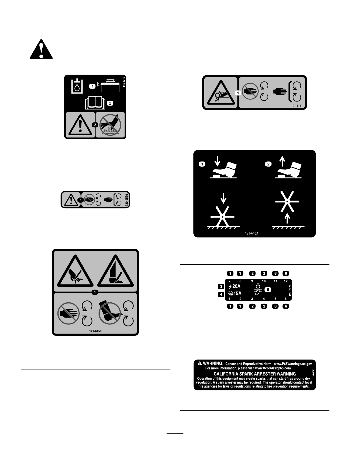
SafetyandInstructionalDecals
Safetydecalsandinstructionsareeasilyvisibletotheoperatorandarelocatednearanyarea
ofpotentialdanger.Replaceanydecalthatisdamagedormissing.
115-4212
decal121-6161
121-6161
1.Entanglementhazard,belt—stayawayfrommovingparts;
keepallguardsinplace.
decal115-4212
1.Hydraulic-uidlevel
3.Warning—donottouchthe
hotsurface.
2.ReadtheOperator's
Manual.
120-9570
1.Warning—stayawayfrommovingparts;keepallguards
andshieldsinplace.
decal120-9570
decal121-6163
121-6163
1.Presstolowerthetines.2.Releasetoraisethetines.
decal126-7875
126-7875
121-6150
1.Cuttinghazardofhandandfoot—stayawayfrommoving
parts.
1.Fuselocation
decal121-6150
2.Relaylocation
3.Main(20A)
4.Auxiliary(15A)
5.Startrelay
6.Notused
decal133-8062
133-8062
5
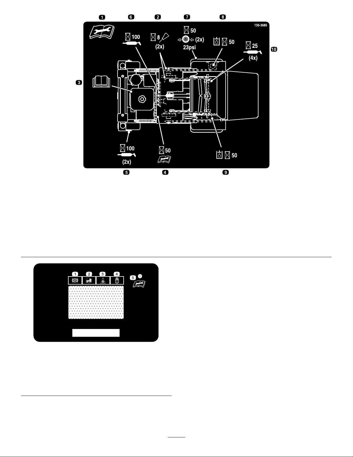
decal135-3685
135-3685
1.ReadandunderstandtheOperator’sManualbeforeservicing
6.Greasethebeltidlerpivotevery100hours
thismachine.
2.Cleanandoilthechainsandcheckthechaintensiontwice
7.Checkthetirepressure-23psitwiceevery50hours
every8hours
3.Seetheengineowner’smanualforservice8.Checkthehydraulicoilleveltwice(Useonlyrecommended
hydraulicuid)every50hours
4.Checktheauxiliarypumpdrivebelttensionevery50hours9.Checktheauxiliaryhydraulictank(UseonlyAW-32hydraulic
uid)every50hours
5.Greasethefrontcasterwheelbearingstwiceevery100hours10.Greasethetineshaftbearings4timesevery25hours
decal135-1854
135-1854
1.Parkingbrake4.Depthsetting—lock
2.Tineengagementlockout
switch
3.Tines—down
5.ReadtheOperator’s
Manualbeforeperforming
maintenance.
6

STOP
LB
KG
135-2013
2
1
3
4
5
6
7
8
9
10
decal135-2013-1
135-2013
1.Operatorweightadjustment
5.Throttle—slow9.Parkingbrake—engage
2.Increase6.Engine—on10.Parkingbrake—release
3.Decrease7.Engine—start
4.Throttle—fast8.Engine—off
135-2014
1.Fast6.Wheelsandtinesrotatewhenmoving
backward.
2.Slow7.Warning—readtheOperator’sManual.12.Warning—shutofftheengine,engage
3.Neutral8.Warning—keepbystandersaway.13.Tippinghazard—donotoperatethe
4.Reverse
9.Cutting/dismembermenthazardoffoot;
Cutting/dismembermenthazardof
hand—stayawayfrommovingparts;
keepallguardsandshieldsinplace.
5.Wheelsandtinesrotatewhenmoving
forward.
10.Warning—alloperatorsshouldbe
trainedbeforeoperatingthemachine.
11.Thrownobjecthazard—pickupdebris
beforeoperatingthemachine.
theparkingbreak,andremovethekey
beforeleavingthemachine.
machineneardrop-offs.
14.Tippinghazard—donotturnsharply
whiletravelingfast;driveslowlywhen
turning.
15.Tippinghazard—whenloadingontoa
trailer,donotusedualramps;onlyuse
asingularrampwideenoughforthe
machine.
decal135-2014
7

135-2016
1.Electronictinedepth-decrease
2.Electronictinedepth-increase
3.Pressandhold1secondtoturnon—tineground
engagementfootswitchunlock
4.Pressandhold1secondtoturnoff—tineground
engagementfootswitchlock
135-3183
decal135-2016
decal135-3183
1.Bypassleverpositionfor
pushingthemachine.
2.Readtheinstructions
beforeservicingor
performingmaintenance.
3.Bypassleverpositionfor
operatingthemachine.
8

Setup
LooseParts
Usethechartbelowtoverifythatallpartshavebeenshipped.
ProcedureDescription
3
4
5
MediaandAdditionalParts
Description
Operator'sManual
Key2
Nopartsrequired
Nopartsrequired
Nopartsrequired
1
CheckingTireAirPressure
NoPartsRequired
Qty.
Qty.
–
–
–
1
Readbeforeoperatingthemachine.
Startthemachine.
Checkthebatterycharge.
Checkingthetransmissionuid.
Checktheauxiliaryhydraulicuidlevel.
Use
Use
3
CheckingtheBattery
Charge
Procedure
Checktheairpressureinthedrivetires,andadjust
thepressureasneeded;refertoCheckingtheDrive
TireAirPressure(page39).
Note:Youdonotadjustairpressureforthe
semi-pneumaticcastertires.
2
ServicingtheEngineOil
NoPartsRequired
Procedure
Theengineisshippedwithoil;checktheengine-oil
leveland,ifnecessary,addoiltothespeciedlevel;
refertoEngine-OilSpecications(page33)and
CheckingtheEngine-OilLevel(page33).
NoPartsRequired
Procedure
Themachineisshippedwithalled,lead-acidbattery ,
Checkthechargeofthebatteryand,ifnecessary ,
chargeit;refertoChargingtheBattery(page38).
9

4
CheckingtheTransmission
Fluid
NoPartsRequired
Procedure
Thetransmissionisshippedwithtransmissionuid.
Checkthetransmissionuidleveland,ifnecessary,
adduidtothespeciedlevel;refertoTransmission
FluidSpecication(page46)andCheckingthe
TransmissionFluidLevel(page46).
5
ChecktheAuxiliary
HydraulicFluidLevel
NoPartsRequired
Procedure
Theauxiliaryhydraulicreservoirisshippedwith
hydraulicuid.Checkthehydraulicreservoiruid
leveland,ifnecessary,adduidtothespeciedlevel;
refertoAuxiliaryHydraulicFluidSpecication(page
44)andCheckingtheAuxiliaryHydraulicFluidLevel
(page44).
10
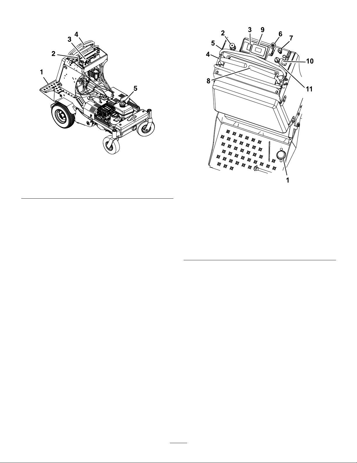
ProductOverview
g232039
Figure4
Controls
1.Platform
2.Parkingbrakelever5.Fuelcap
3.Enginecontrols
4.Motion-controllevers
Figure5
1.Tinegroundengagement
footswitch
2.Operatorweight
adjustmentcontrol
3.Multi-functionswitch
4.Leftmotion-controllever
5.Frontreferencebar
6.Throttle
7.Choke
8.Rightmotion-controllever
9.Hourmeter
10.Parking-brakehandle
11.Ignitionswitch
TineGroundEngagementFoot
Switch
Keepyourhandsandfeetawayfromthe
tines.Ensurethatthetinesareaisclearofany
obstructionsbeforeloweringit.
Theswitchislocatedontheoperatorplatform(Figure
5).
Tolowerthetinesintotheground,standonthe
tinegroundengagementswitch.T oraisethetines,
removeyourfootfromtheswitch.
g223341
Thisswitchcanbelockedout(disabled)withthe
multi-functionswitch.
•Tapandholdthebottomoftheswitchtooverride
andlockout(disable)thefootswitch.TheLED
illuminatesinthehourmeter/tineengagement
display.Usethisfeaturewhentransportingthe
aerator.
•Tounlock,tapandholdthetopofthemulti-function
switchuntiltheLEDlightdisappears.
11

Note:Thelockoutfeatureisengagedeachtimethe
engineisswitchedoff.
OperatorWeightAdjustment
Control
Theoperatorweightadjustmentvalveislocatedatthe
leftsideofthecontrolconsole(Figure6).
Important:Thetinesrotatewhenthe
motion-controlleversaremovedoutofthe
NEUTRALposition.
g223330
Figure7
g249578
Figure6
1.Operatorweightadjustmentcontrol
Usetheoperatorweightadjustmentvalvetohelp
compensatefortheweightoftheoperatorsothatthe
machineachievesthecorrectaeratingpressure,plug
length,andtohelpmaximizelateralmachinestability.
Note:Eachoperatormustadjustthesystempressure
sothatthedrivetireslightlytouchtheground.
Important:Keepthedrivetiresonthegroundat
alltimestomaximizelateralmachinestability.
Multi-FunctionSwitch
Themulti-functionswitchislocatedtotheleftofthe
hourmeter/tineengagementdisplay(Figure5).
Thisswitchallowstheoperatortodothefollowing:
•increaseordecreasethedepthofaerationplug
•lockorunlockthetinedepthsetting
•resetmaintenanceservicereminderscreens
Motion-ControlLevers
1.Leftmotion-controllever
2.Rightmotion-controllever6.Neutral
3.Frontreferencebar
4.Frontofmachine8.Rearreferencebar
5.Forward
7.Reverse
ThrottleLever
Thethrottlelever(Figure5)islocatedonthecontrol
console(redlever).
Usethethrottlelevertocontrolenginespeed.Move
thethrottleleverforwardtoincreaseenginespeed;
movingthethrottleleverrearwardtodecreasethe
enginespeed.
Note:Movethethrottleleverforwardintothedetent
forfullthrottle.
ChokeControl
Thechokecontrol(Figure5)islocatedonthecontrol
console.
Usethechokecontroltoaidinstartingacoldengine.
PulloutthechokecontroltosetthechoketotheON
position;pressinthechokelevertoreducethechoke.
Note:Pulloutthechokecontroltosetthechoketo
theONposition.
Note:Donotrunawarmenginewiththechokein
theONposition.
Themotion-controlleversarelocatedoneachsideof
thetopconsoleandcontroltheforwardandreverse
motionofthemachine(Figure7).
Movetheleversforwardorbackwardtocontrolthe
drivewheelonthesamesideforwardorreverse
respectively.Thewheelspeedisproportionaltothe
amountyoumovethelever.
HourMeter/TineEngagement
Display
SmartController/ElectronicDepthControl
Thehourmeter/tineengagementdisplayislocatedto
theleftoftheignitionswitchonthecontrolconsole
(Figure5).
12

Usethehourmeter/tineengagementdisplaytoshow
thefollowinginformationgeneratedbythesmart
controller/electronicdepthcontrolsystem:
AeratingHoursElectronicdepth
AlertandError
Messages
BatteryvoltageInterlockstatus
controlsetting
indicatorforthe
tines
EngineHoursMaintenance
Parkingbrake
indicator
Remindersand
Alerts
LEDStatusLight
RefertoUsingtheSmartController/ElectronicDepth
Control(page19)formoreinformation.
HourMeterDisplay
Thehourmeter(Figure8)monitorsanddisplaystotal
enginehours.
Note:Theenginehoursdisplaywhentheignitionkey
isintheOFFpositionorwhiletheengineisrunning.
Theenginehoursdonotdisplaywhilethemachine
isaerating.
g211731
Figure9
1.LCDIndicators/Informationscreen
2.Tinedepthstatusbar
3.Tinedepthsettingindicator
4.LEDstatuslight
LEDStatusLight
TheLEDstatuslightislocatedattherightsideofthe
hourmeter/tineengagementdisplay(Figure8and
Figure9).
TheLEDismulti-coloredtoindicatethesystemstatus.
Figure8
1.LCDIndicators/Informationscreen
2.Hourdisplay
3.LEDstatuslight
TineEngagementDisplay
Thetineengagementdisplay(Figure9)monitorsand
showstheelectronictinedepthsetting.
Parking-BrakeHandle
Theparking-brakehandleislocatedonthecontrol
console,totherightofthekeyswitch(Figure5).
Note:Thebrakehandleengagesaparkingbrakein
eachofthetransmissions.
•T oengagetheparkingbrake,pullthehandleback
g211730
towardyou.
•T oreleasetheparkingbrake,pushthehandleall
thewayforwardawayfromyou.
Whenparkingonaslope,chockorblockthewheels
inadditiontoengagingtheparkingbrake.Tiedown
themachineandengagetheparkingbrakewhen
transportingthemachine.
IgnitionSwitch
TheIgnitionswitchislocatedontherightsideofthe
controlconsole(Figure5).
UsetheIgnitionkeytostartandshutofftheengine.
Theswitchhas3positions:OFF,ON,andSTART
(Figure10).
13

Specications
Figure10
1.OFF3.START
2.ON
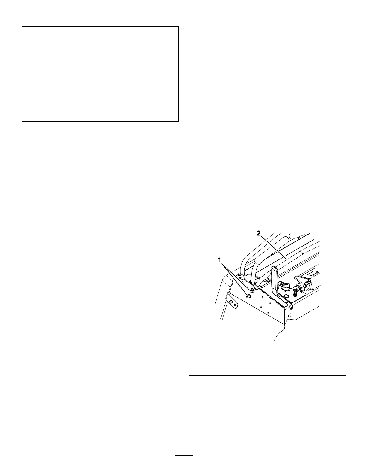
Fuel-ShutoffLever
Thefuel-shutoffleverislocatedundertheaircleaner
atthefrontrightsideoftheengine(Figure11).
Height
Length
Width
RPM(FullSpeed)3800±100rpm(noload)
Aerationwidth
g008610
Coringrange1.3to12.7cm(0.5to5inches)
Holespersquarefoot
Tines36
Weight
129.5cm(51inches)
173.2cm(68.6inches)
90.2cm(35.5inches)
61cm(24inches)
4.6
388kg(856lb)
AselectionofToroapprovedattachmentsand
accessoriesisavailableforusewiththemachine
toenhanceandexpanditscapabilities.Contact
yourAuthorizedServiceDealerorauthorizedT oro
distributororgotowww.Toro.comforalistofall
approvedattachmentsandaccessories.
Toensureoptimumperformanceandcontinuedsafety
certicationofthemachine,useonlygenuineT oro
replacementpartsandaccessories.Replacement
partsandaccessoriesmadebyothermanufacturers
couldbedangerous,andsuchusecouldvoidthe
productwarranty.
Figure11
1.Aircleaner
2.Fuel-shutofflever
Usethefuel-shutofflevertoshutoffthefuelwhenyou
arenotusingthemachineforafewdays,whileyou
aretransportingthemachinetoandfromthejobsite,
orwhenthemachineisparkedinsideabuilding.
g281826
14

Operation
BeforeOperation
BeforeOperationSafety
GeneralSafety
CAUTION
Thismachineproducessoundlevelsin
excessof85dBAattheoperator’searand
cancausehearinglossthroughextended
periodsofexposure.
Wearhearingprotectionwhenoperatingthis
machine.
FuelSafety
•Useextremecareinhandlingfuel.Itisammable
anditsvaporsareexplosive.
•Extinguishallcigarettes,cigars,pipes,andother
sourcesofignition.
•Useonlyanapprovedfuelcontainer.
•Donotremovethefuelcaporllthefueltank
whiletheengineisrunningorhot.
•Donotaddordrainthefuelinanenclosedspace.
•Donotstorethemachineorfuelcontainerwhere
thereisanopename,spark,orpilotlight,such
asonawaterheaterorotherappliance.
•Ifyouspillfuel,donotattempttostarttheengine;
avoidcreatinganysourceofignitionuntilthefuel
vaporshavedissipated.
AddingFuel
•Evaluatetheterraintodeterminewhataccessories
andattachmentsareneededtoproperlyand
safelyperformthejob.Onlyuseaccessoriesand
attachmentsapprovedbyToro.
•Inspecttheareawheretheequipmentistobe
usedandremoveallrocks,toys,sticks,wires,
bones,andotherforeignobjects.Thesecan
bethrownorinterferewiththeoperationofthe
machineandmaycausepersonalinjurytothe
operatororbystanders.
•Markandavoidhiddenobjectssuchassprinkler
heads,undergroundwires/cables,invisiblefences,
etc.topreventdamagetothesesystemswhen
aerating.
•Wearappropriatepersonalprotectiveequipment
suchassafetyglasses,substantialslip-resistant
footwear,andhearingprotection.Tiebacklong
hairandavoidlooseclothingandloosejewelry
whichmaygettangledinmovingparts.
•Checkthattheoperatorpresencecontrols,
safetyswitches,andshieldsareattachedand
functioningproperly.DoNotoperateunlessthey
arefunctioningproperly.
DANGER
Incertainconditions,fuelisextremely
ammableandhighlyexplosive.Areor
explosionfromfuelcanburnyouandothers
andcandamageproperty.
•Fillthefueltankoutdoors,inanopenarea,
andwhentheengineiscold.Wipeupany
fuelthatspills.
•Donotllthefueltankcompletelyfull.
Addfueltothefueltankuntilthelevelis6
to13mm(1/4to1/2inch)belowthebottom
ofthellerneck.Thisemptyspaceinthe
tankallowsthefueltoexpand.
•Neversmokewhenhandlingfuel,andstay
awayfromanopenameorwhereaspark
mayignitethefuelfumes.
•Storefuelinanapprovedfuelcontainer
andkeepitoutofthereachofchildren.
•Neverbuymorethana30-daysupplyof
fuel.
•DoNotoperatethemachinewhenpeople,
especiallychildren,orpetsareinthearea.Stop
themachineandattachment(s)ifanyoneenters
thearea.
•DoNotoperatethemachinewithdamagedguards,
shields,orcovers.Alwayshavesafetyshields,
guards,switchesandotherdevicesinplaceand
inproperworkingcondition.Frequentlycheckfor
wornordeterioratingcomponentsandreplace
themwiththemanufacturer’srecommendedparts
whennecessary.
WARNING
Fuelisharmfulorfatalifswallowed.
Long-termexposuretovaporscancause
seriousinjuryandillness.
•Avoidprolongedbreathingofvapors.
•Keepyourfaceawayfromthenozzleand
fueltankorconditionerbottleopening.
•Avoidcontactwithskin;washoffspills
withsoapandwater.
15
FuelSpecication
Petroleum
fuel
Ethanol
blended
fuel
Useunleadedgasolinewithanoctaneratingof87
orhigher((R+M)/2ratingmethod).
Useanunleaded-gasolineblendwithupto10%
ethanol(gasohol)or15%MTBE(methyltertiary
butylether)byvolumeisacceptable.Ethanoland
MTBEarenotthesame.
Gasolinewith15%ethanol(E15)byvolumeis
notapprovedforuse.Neverusegasolinethat
containsmorethan10%ethanolbyvolume,such
asE15(contains15%ethanol),E20(contains
20%ethanol),orE85(containsupto85%
ethanol).Usingunapprovedgasolinemaycause
performanceproblemsand/orenginedamage
whichmaynotbecoveredunderwarranty.
•LubricatingtheChains(page31)
•CheckingtheEngine-OilLevel(page33)
•CheckingtheSafetyInterlock(page36)
•CheckingtheConditionoftheChains(page40)
•CheckingtheSprocketCondition(page40)
•CheckingtheTines(page48)
•CheckforLooseHardware(page50)
•CleaningtheEngineandtheExhaustSystem
Area(page50)
•CleaningtheDebrisfromtheMachine(page51)
Important:Forbestresults,useonlyclean,fresh
fuel(lessthan30daysold).
•Donotusegasolinecontainingmethanol.
•Donotstorefueleitherinthefueltankorfuel
containersoverthewinterunlessyouuseafuel
stabilizer.
•Donotaddoiltogasoline.
UsingStabilizer/Conditioner
Usefuelstabilizer/conditionerinthemachineatall
timestokeepthefuelfreshlongerwhenusedas
directedbythefuel-stabilizermanufacturer.
Important:Donotusefueladditivescontaining
methanolorethanol.
Addtheamountoffuelstabilizer/conditionertofresh
fuelasdirectedbythefuel-stabilizermanufacturer.
FuelingtheMachine
Fuel-tankcapacity:7L(1.9USgallons)
AdjustingtheFront
Reference/SpeedControl
Bar
Adjustthefrontreference/speedcontrolbarfor
desiredmaximumforwardspeed.
1.Shutofftheengine,engagetheparkingbrake,
andmovethemotioncontrolleverstotheneutral
position.
2.Loosentheboltsonbothsidesofthecontrol
towerbylooseningthe2nutsoneachside(four
total)oftheconsole(seeFigure12).
1.Cleanaroundthefuel-tankcap.
2.Removethecapfromthetank.
3.Fillthefueltankwithfueltowithin6to13mm
(1/4to1/2inch)fromthetopofthetank.Donot
llintothellerneck.
Important:Donotllthetankmorethan
6mm(1/4inch)fromthetopofthetank
becausethefuelmusthaveroomtoexpand.
4.Installthefuel-tankcapandwipeupanyspilled
fuel.
PerformingDaily
Maintenance
Beforestartingthemachineeachday,performeach
use/dailymaintenanceproceduresthatfollow:
Figure12
1.Nuts
3.Movethebarforwardtoobtainthefastestspeed.
Movethebarbackwardtoobtaintheslowest
speed.
4.Onbothsides,tightenthenutsandbolts.
2.Frontreference/speed
controlbar
Important:Makesurethatthenutsandboltsare
tight,sothefrontreference/speedcontrolbar
doesnotmoveduringoperation.
16
g231460
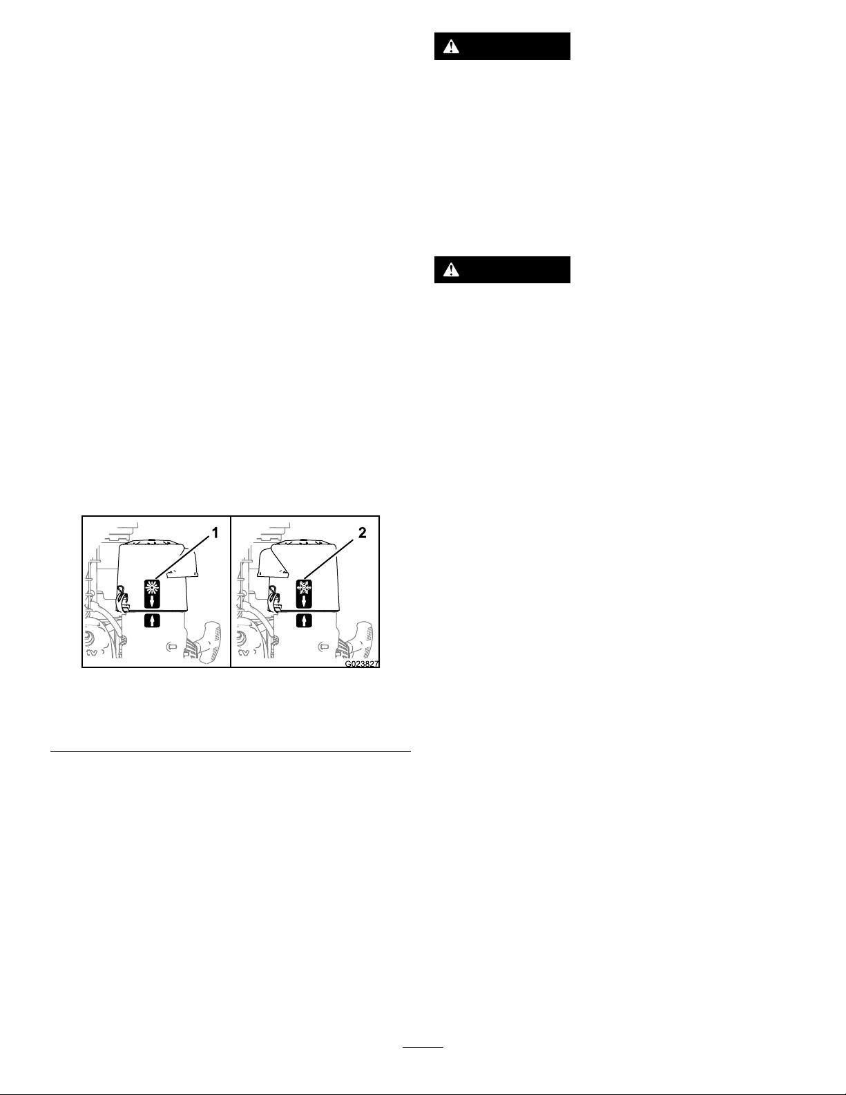
PositioningtheAir-Cleaner
WARNING
CoverforColdorWarmAir
Temperature
Important:Runningtheenginewiththe
air-cleanercoverpositionedforcold-weather
operationinnormalconditionscandamagethe
engine.
Theair-cleanercoverhas2positions:thecoldor
normal,ambientairpositions:
Adjusttheair-cleanercoverasfollows:
•Whenoperatinginacoldambientaircondition
(coldairtemperatureandhumidity)—positionthe
air-cleanercoverwithsnowakedecalfacingout
(Figure13).
Note:Usethispositionifyourmachineexhibits
carburetoricing.Symptomsincludetheengine
runsroughatidleorlowspeed,anditdischarges
blackorwhitesmokeintheexhaust.
•Whenoperatinginanormalambientair
condition—positiontheair-cleanercoverwithsun
decalfacingout(Figure13).
Note:Usethispositionifyourmachineisnot
exhibitingcarburetoricing.
Operatingengineparts,especiallythemufer,
becomeextremelyhot.Severeburnscan
occuroncontactanddebris,suchasleaves,
grass,brush,etc.cancatchre.
•Allowengineparts,especiallythemufer,
tocoolbeforetouching.
•Removeaccumulateddebrisfrommufer
andenginearea.
WARNING
Engineexhaustcontainscarbonmonoxide,
whichisanodorlessdeadlypoisonthatcan
killyou.
DoNotrunengineindoorsorinasmall
connedareawheredangerouscarbon
monoxidefumescancollect.
•Theowner/usercanpreventandisresponsible
foraccidentsorinjuriesoccurringtohimselfor
herself,otherpeopleorproperty .
•Thismachinewasdesignedforoneoperatoronly.
Donotcarrypassengersandkeepallothersaway
frommachineduringoperation.
Figure13
1.Normalambientair
position
2.Coldambientairposition
DuringOperation
Note:Determinetheleftandrightsidesofthe
machinefromthenormaloperatingposition.
DuringOperationSafety
GeneralSafety
Theoperatormustusetheirfullattentionwhen
operatingthemachine.DoNotengageinanyactivity
thatcausesdistractions;otherwise,injuryorproperty
damagemayoccur.
•DoNotoperatethemachineundertheinuence
ofalcoholordrugs.
•Operateonlyindaylightorgoodarticiallight.
•Lightningcancausesevereinjuryordeath.If
lightningisseenorthunderisheardinthearea,
DoNotoperatethemachine;seekshelter.
g023827
•Useextracarewhileoperatingwithaccessoriesor
attachments.Thesecanchangethestabilityof
themachineandcausealossofcontrol.Follow
directionsforcounterweightsifrequired.
•Keepawayfromholes,ruts,bumps,rocks,and
otherhiddenhazards.Usecarewhenapproaching
blindcorners,shrubs,trees,tallgrassorother
objectsthatmayhideobstaclesorobscurevision.
Uneventerraincouldoverturnthemachineor
causetheoperatortolosetheirbalanceorfooting.
•Besurealldrivesareinneutralandparkingbrake
isengagedbeforestartingengine.
•Starttheenginecarefullyaccordingtoinstructions
withfeetwellawayfromthetines.
•Neveroperatethemachinewithdamagedguards,
shields,orcovers.Alwayshavesafetyshields,
guards,switchesandotherdevicesinplaceandin
properworkingcondition.
•Keepclearofthetinesatalltimes.
17

•Keephandsandfeetawayfrommovingparts.
Ifpossible,DoNotmakeadjustmentswiththe
enginerunning.
WARNING
Hands,feet,hair,clothing,oraccessories
canbecomeentangledinrotatingparts.
Contactwiththerotatingpartscan
causetraumaticamputationorsevere
lacerations.
–DoNotoperatethemachinewithout
guards,shields,andsafetydevicesin
placeandworkingproperly.
–Keephands,feet,hair,jewelry,or
clothingawayfromrotatingparts.
•Beawareofthedischargepathanddirect
dischargeawayfromothers.Avoiddischarging
materialagainstawallorobstructionasthe
materialmayricochetbacktowardtheoperator.
Raisethetines,slowdown,andusecautionwhen
crossingsurfacesotherthangrassandwhen
transportingthemachinetoandfromthework
area.
•Bealert,slowdownandusecautionwhenmaking
turns.Lookbehindandtothesidebeforechanging
directions.DoNotoperateinreverseunless
absolutelynecessary.
•DoNotchangetheenginegovernorsettingor
overspeedtheengine.
•Parkthemachineonlevelground.Stopengine,
waitforallmovingpartstostop,andremovethe
sparkplugwire(s).
–Beforechecking,cleaningorworkingonthe
machine.
–Afterstrikingaforeignobjectorabnormal
vibrationoccurs(inspectthemachinefor
damageandmakerepairsbeforerestarting
andoperatingthemachine).
–Beforeclearingblockages.
–Wheneveryouleavethemachine.DoNot
leavearunningmachineunattended.
–Bealertandturnthemachineoffifchildren
enterthearea.
–Beforeandwhilebackingorchangingdirection,
lookbehind,down,andside-to-sideforsmall
children.
–Neverallowchildrentooperatethemachine.
–DoNotcarrychildren,evenwiththeblades
shutoff.Childrencouldfalloffandbeseriously
injuredorinterferewiththesafeoperationof
themachine.Childrenthathavebeengiven
ridesinthepastcouldsuddenlyappearinthe
workingareaforanotherrideandberunover
orbackedoverbythemachine.
SlopeSafety
•Slopesareamajorfactorrelatedtolossofcontrol
androlloveraccidents,whichcanresultinsevere
injuryordeath.Theoperatorisresponsiblefor
safeslopeoperation.Operatingthemachineon
anysloperequiresextracaution.Beforeusingthe
machineonaslope,theoperatormust:
–Reviewandunderstandtheslopeinstructions
inthemanualandonthemachine.
–Evaluatethesiteconditionsofthedayto
determineiftheslopeissafeformachine
operation.Usecommonsenseandgood
judgmentwhenperformingthisevaluation.
Changesintheterrain,suchasmoisture,can
quicklyaffecttheoperationofthemachineon
aslope.
•Operateacrossslopes,neverupanddown.Avoid
operationonexcessivelysteeporwetslopes.
•Identifyhazardsatthebaseoftheslope.Do
notoperatethemachineneardropoffs,ditches,
embankments,waterorotherhazards.The
machinecouldsuddenlyrolloverifawheelgoes
overtheedgeortheedgecollapses.Keepasafe
distance(twicethewidthofthemachine)between
themachineandanyhazard.Useawalkbehind
machineorahandheldtooltooperateinthese
areas.
•Stopengine,waitforallmovingpartstostop:
–Beforerefueling.
•Tragicaccidentscanoccuriftheoperatorisnot
alerttothepresenceofchildren.Childrenare
oftenattractedtothemachineandtheworking
activity.Neverassumethatchildrenwillremain
whereyoulastsawthem.
–Keepchildrenoutoftheworkingareaand
underthewatchfulcareofanotherresponsible
adult,nottheoperator.
18
 Loading...