

Page 1
FormNo.3421-850RevB
24inStand-OnAerator
ModelNo.39514—SerialNo.400000000andUp
Registeratwww.T oro.com.
OriginalInstructions(EN)
*3421-850*B
Page 2
Important:Thisengineisnotequippedwitha
sparkarrestermufer.ItisaviolationofCalifornia
PublicResourceCodeSection4442tooperatethe
engineonanyforest-covered,brush-covered,or
grass-coveredland.Otherstatesorfederalareas
mayhavesimilarlaws.
Theenclosedengineowner'smanualissupplied
forinformationregardingtheUSEnvironmental
ProtectionAgency(EPA)andtheCaliforniaEmission
ControlRegulationofemissionsystems,maintenance,
andwarranty.Replacementsmaybeorderedthrough
theenginemanufacturer.
WARNING
CALIFORNIA
Proposition65Warning
Theengineexhaustfromthisproduct
containschemicalsknowntotheStateof
Californiatocausecancer,birthdefects,
orotherreproductiveharm.
Batteryposts,terminals,andrelated
accessoriescontainleadandlead
compounds,chemicalsknownto
theStateofCaliforniatocause
cancerandreproductiveharm.Wash
handsafterhandling.
Important:Withyourmobiledevice,youcan
scantheQRcodeontheserialnumberdecal(if
equipped)toaccesswarranty,parts,andother
productinformation.
g246050
Figure1
1.Locationofthemodelandserialnumbers
ModelNo.
SerialNo.
Introduction
Thisaeratorisintendedforusebytrainedoperators
inresidentialandcommercialapplications.The
machineisprimarilydesignedforaeratingareasof
well-maintainedlawnsonresidentialgrounds,parks,
sportselds,andoncommercialgrounds.
Readthisinformationcarefullytolearnhowtooperate
andmaintainyourproductproperlyandtoavoid
injuryandproductdamage.Youareresponsiblefor
operatingtheproductproperlyandsafely .
YoumaycontactTorodirectlyatwww.Toro.com
forproductsafetyandoperationtrainingmaterials,
accessoryinformation,helpndingadealer,orto
registeryourproduct.
Wheneveryouneedservice,genuineToroparts,or
additionalinformation,contactanAuthorizedService
DealerorToroCustomerServiceandhavethemodel
andserialnumbersofyourproductready .Figure1
identiesthelocationofthemodelandserialnumbers
ontheproduct.Writethenumbersinthespace
provided.
Thismanualidentiespotentialhazardsandhas
safetymessagesidentiedbythesafety-alertsymbol
(Figure2),whichsignalsahazardthatmaycause
seriousinjuryordeathifyoudonotfollowthe
recommendedprecautions.
g000502
Figure2
1.Safety-alertsymbol
Thismanualuses2wordstohighlightinformation.
Importantcallsattentiontospecialmechanical
informationandNoteemphasizesgeneralinformation
worthyofspecialattention.
©2018—TheToro®Company
8111LyndaleAvenueSouth
Bloomington,MN55420
Contactusatwww.Toro.com.
2
PrintedintheUSA
AllRightsReserved
Page 3

Contents
Safety.......................................................................4
SafeOperatingPractices....................................4
AeratorSafety....................................................6
SafetyandInstructionalDecals..........................7
Setup.......................................................................11
1CheckingTireAirPressure.............................11
2ServicingtheEngineOil..................................11
3CheckingtheBatteryCharge..........................11
4CheckingtheTransmissionFluid...................12
5ChecktheAuxiliaryHydraulicFluid
Level.............................................................12
ProductOverview...................................................13
Controls...........................................................13
Specications..................................................20
Operation................................................................20
AddingFuel......................................................20
OpeningandClosingtheFuelShutoff
Valve.............................................................21
StartingtheEngine...........................................21
CheckingtheSafetyInterlock...........................22
LoweringtheTines...........................................22
ChangingtheTineDepthSetting......................22
Locking/UnlockingtheTineDepth
Setting...........................................................22
AdjustingtheOperatorWeightControl
Valve.............................................................22
RaisingtheTines..............................................23
ShuttingOfftheEngine.....................................23
DrivingtheMachine..........................................23
PositioningtheAir-CleanerCoverforColdor
WarmAirT emperature..................................24
AdjustingtheFrontReference/Speed
ControlBar....................................................25
LoadingtheMachine........................................25
TransportingtheMachine.................................25
Maintenance...........................................................27
RecommendedMaintenanceSchedule(s)...........27
Pre-MaintenanceProcedures..............................28
PreparingforMaintenance...............................28
Lubrication..........................................................29
LubricatingtheChains......................................29
LubricatingtheGreaseFittings.........................29
EngineMaintenance...........................................30
ServicingtheAirCleaner..................................30
ServicingtheEngineOil....................................30
ServicingtheSparkPlug...................................32
CheckingtheSparkArrester.............................33
ElectricalSystemMaintenance...........................34
JumpStartingtheMachine...............................34
ServicingtheBattery.........................................35
DriveSystemMaintenance..................................36
CheckingtheDriveTireAirPressure.................36
CheckingtheWheelHubBolts..........................36
CheckingtheT orqueoftheWheelLug
Nuts..............................................................36
CheckingtheConditionoftheChains...............36
CheckingtheSprocketCondition......................36
MaintainingtheChain.......................................36
CheckingtheT orqueoftheTransmission
OutputShaftNut...........................................37
AdjustingtheMotionControlLinkage................37
AdjustingtheMotionControlTracking...............37
BrakeMaintenance.............................................38
AdjustingtheParkingBrake..............................38
BeltMaintenance................................................38
CheckingtheConditionandT ensionofthe
Belts..............................................................38
AdjustingtheAuxiliaryPumpDrive
Belt................................................................38
CheckingtheTransmissionDriveBelt
Tension.........................................................38
HydraulicSystemMaintenance...........................39
AuxiliaryHydraulicFluidSpecication..............39
CheckingtheAuxiliaryHydraulicFluid
Level.............................................................39
ChangingtheAuxiliaryHydraulicReservoir
FluidandFilter..............................................39
TransmissionFluidSpecication......................39
CheckingtheTransmissionFluidLevel.............40
ChangingtheHydraulicTransmissionFilters
andFluid.......................................................40
TineMaintenance.................................................41
CheckingtheTines...........................................41
AdjustingtheTineDriveChain..........................42
AdjustingtheReturn-to-UpSpring....................42
Cleaning..............................................................43
CleaningtheEngineandtheExhaust
SystemArea.................................................43
RemovingtheEngineShroudsandCleaning
theCoolingFins............................................43
CleaningtheDebrisfromtheMachine...............43
DisposingofWaste...........................................43
Storage...................................................................44
Troubleshooting......................................................45
3
Page 4

Safety
Improperuseormaintenancebytheoperatororowner
canresultininjury.Toreducethepotentialforinjury,
complywiththesesafetyinstructionsandalwayspay
attentiontothesafety-alertsymbol(Figure2),which
meansCaution,Warning,orDanger—personalsafety
instruction.Failuretocomplywiththeinstructionmay
resultinpersonalinjuryordeath.
WARNING
Removingormodifyingoriginalequipment,
partsand/oraccessoriesmayalterthe
warranty,controllability ,andsafetyofthe
machine.Unauthorizedmodicationstothe
originalequipmentorfailuretouseoriginal
Toropartscouldleadtoseriousinjuryor
death.Unauthorizedchangestothemachine,
engine,fuelorventingsystem,mayviolate
applicablesafetyandgovernmentstandards.
Replaceallpartsincluding,butnotlimitedto,
tires,belts,andfuelsystemcomponentswith
originalT oroparts.
Thisproductiscapableofinjuringyourhandsand
feet.Followallsafetyinstructionstoavoidserious
injuryordeath.
Theowner/usercanpreventandisresponsiblefor
accidentsorinjuriesoccurringtopeople,ordamage
toproperty.
Anyuseofthismachineotherthanaeratingturfgrass
couldprovedangeroustoyouandbystanders.
Important:Theadditionofattachmentsmade
byothermanufacturersthatdonotmeetANSI
certicationmaycausenoncomplianceofthis
machine.
SafeOperatingPractices
ThefollowinginstructionsarefromANSIstandard
B71.4-2012.
Training
•ReadtheOperator'sManualandothertraining
material.Iftheoperator(s)ormechanic(s)cannot
readthemanuallanguage,itistheowner's
responsibilitytoexplainthismaterialtothem.
•Becomefamiliarwiththesafeoperationofthe
equipment,operatorcontrols,andsafetysigns.
•Alloperatorsandmechanicsshouldbetrained.
Theownerisresponsiblefortrainingtheusers.
•Neverletchildrenoruntrainedpeopleoperateor
servicetheequipment.Localregulationsmay
restricttheageoftheoperator.
•Theowner/usercanpreventandisresponsible
foraccidentsorinjuriesoccurringtohimselfor
herself,otherpeople,ordamagetoproperty.
Preparation
•Locateandmarkundergroundhazards.
•Evaluatetheterraintodeterminewhataccessories
andattachmentsareneededtoproperlyand
safelyperformthejob.Useonlyaccessoriesand
attachmentsapprovedbythemanufacturer.
•Wearappropriateclothing;includingsafety
glasses,longpants,substantial,slip-resistant
footwear,gloves,andhearingprotection.Tieback
longhair.Donotwearloosejewelry.
•Inspecttheareawhereyouwillusetheequipment
andremoveallobjectsfromtheareabeforeusing
themachine.
•Useextracarewhenhandlingfuels.Theyare
ammableanditsvaporsareexplosive.
–Useonlyanapprovedcontainer.
–Donotremovethefuelcaporaddfuelwiththe
enginerunning.Allowtheenginetocoolbefore
refueling.Donotsmokenearthemachine
whentheengineisrunning.
–Donotrefuelordrainthemachineindoors.
•Checkthattheoperator'spresencecontrols,safety
switches,andshieldsareattachedandfunctioning
properly.Donotoperatethemachineunlessthey
arefunctioningproperly.
4
Page 5

Operation
•Donotoperatethemachinewhenthereistherisk
oflightning.
•Donotrunanengineinanenclosedarea.
•Operatethemachineonlyinwell-litareas,keeping
awayfromholesandhiddenhazards.
•Ensurethatalldrivesareinneutralandthatthe
parkingbrakeisengagedbeforestartingthe
engine.Starttheengineonlyfromtheoperator’s
position.
•Ensurethatyouhavegoodfootingwhileusingthis
machine,especiallywhenbackingup.Reduced
footingcouldcauseslipping.
•Slowdownanduseextracareonhillsides.Be
suretotravelsidetosideonhillsides.Turf
conditionscanaffectthestabilityofthemachine.
Usecautionwhileoperatingneardrop-offs.
•Slowdownandusecautionwhenmakingturns
andwhenchangingdirectionsonslopes.
•Donotoperatethemachinewithouttheshields
orotherguardssecurelyinplace.Ensurethatall
interlocksareattached,adjustedproperly,and
functioningproperly.
•Donotchangetheenginegovernorsettingor
overspeedtheengine.
•Stoponlevelground,disengagedrives,engage
theparkingbrake(ifprovided),shutofftheengine,
andremovethekeybeforeleavingtheoperator's
positionforanyreason.
•Stopequipment,shutofftheengine,removethe
key,andinspectthetinesafterstrikingobjectsorif
anabnormalvibrationoccurs.Makethenecessary
repairsbeforeresumingoperations.
•Keepyourhandsandfeetawayfromthetine
assembly.
•Lookbehindanddownbeforebackingupto
ensureaclearpath.
•Stopthemachineifanyoneentersthearea.Keep
petsandbystandersawayfromanoperating
machine.
•Slowdownandusecautionwhenmakingturns
andcrossingroadsandsidewalks.Fullyraisethe
tinesifyouarenotaerating.
•Donotoperatethemachinewhileill,tired,or
undertheinuenceofalcoholordrugs.
•Usecarewhenloadingorunloadingthemachine
intoorfromatrailerortruck.
•Usecarewhenapproachingblindcorners,shrubs,
trees,orotherobjectsthatmayobscurevision.
SafeHandlingofFuels
•Toavoidpersonalinjuryorpropertydamage,use
extremecareinhandlingfuel.Fuelisextremely
ammableandthevaporsareexplosive.
•Extinguishallcigarettes,cigars,pipes,andother
sourcesofignition.
•Useonlyanapprovedfuelcontainer.
•Donotremovethefuelcaporaddfuelwiththe
enginerunning.
•Allowtheenginetocoolbeforefueling.
•Donotfuelthemachineindoors.
•Donotstorethemachineorfuelcontainerwhere
thereisanopename,spark,orpilotlight,such
asonawaterheateroronotherappliances.
•Donotllcontainersinsideavehicle,onatruck,
oronatrailerbedwithaplasticliner.Alwaysplace
containersonthegroundawayfromyourvehicle
beforelling.
•Removeequipmentfromthetruckortrailerand
fuelitontheground.Ifthisisnotpossible,
thenaddfuelwithsuchequipmentasaportable
containerratherthanfromafuel-dispensernozzle.
•Keepthenozzleincontactwiththerimofthefuel
tankorcontaineropeningatalltimesuntilfueling
iscomplete.Donotuseanozzlelock-opendevice.
•Iffuelisspilledonclothing,changeyourclothing
immediately.
•Donotoverllthefueltank.Replacethefuelcap
andtightenitsecurely.
MaintenanceandStorage
•Donotallowuntrainedpersonneltoservicethe
machine.
•Donottouchequipmentorattachmentpartsthat
maybehotfromoperation.Allowallofthepartsof
themachinetocoolbeforeattemptingtomaintain,
adjust,orservicethemachine.
•Keepyourhandsandfeetawayfrommoving
parts.Ifpossible,donotmakeadjustmentswith
theenginerunning.
•Disengagethedrives,raisethetines,engagethe
parkingbrake,shutofftheengine,andremove
thekeyordisconnectthespark-plugwire.Waitfor
allmovementtostopbeforeadjusting,cleaning,
orrepairing.
•Disconnectthebatteryorremovethespark-plug
wirebeforemakinganyrepairs.Disconnectthe
negativeterminalrstandthepositiveterminal
last.Connectthepositiverstandnegativelast.
•Usecarewhencheckingthetines.Wrapthetine(s)
orweargloves,andusecautionwhenservicing
them.Onlyreplacetines;donotstraightenorweld
them.
5
Page 6

•Cleangrass,dirt,anddebrisfromthetines,drives,
mufers,andenginetohelppreventres.
•Cleanupoilorfuelspills.
•Parkmachineonlevel,hardground.Neverallow
untrainedpersonneltoservicethemachine.
•Usejackstandstosupportcomponentswhen
required.
•Carefullyreleasepressurefromcomponentswith
storedenergy.
•Donotstorefuelnearamesordrainthefuel
indoors.
•Lettheenginecoolbeforestoringthemachine.
•Keepallpartsingoodworkingconditionandall
hardwaretightened.Replaceallwornordamaged
decals.
Hauling
•Usecarewhenloadingorunloadingthemachine
intoatraileroratruck.
•Useafull-widthrampforloadingthemachineinto
atraileroratruck.
•Tiethemachinedownsecurelyusingstraps,
chains,cable,orropes.Bothfrontandrearstraps
shouldbedirecteddownandoutwardfromthe
machine.
AeratorSafety
Thefollowinglistcontainssafetyinformationspecic
toToroproductsandothersafetyinformationyou
mustknow.
GeneralOperation
•Checkcarefullyforoverheadclearances(i.e.,
branches,doorways,electricalwires,etc.)before
operatingunderanyobjects,anddonotcontact
them.
•Usecautionwhenyouareridingontheplatform
anddrivingthemachineovercurbs,rocks,roots,
orotherobstructions.
•Donotjerkthecontrols;useasteadymotion.
•Donotcarrypassengers.
•Donotcarryequipmentonthemachine.
SlopeOperation
•Slopesareamajorfactorrelatedtolossofcontrol
androlloveraccidents,whichcanresultinsevere
injuryordeath.Theoperatorisresponsiblefor
safeslopeoperation.Operatingthemachineon
anysloperequiresextracaution.Beforeusingthe
machineonaslope,dothefollowing:
–Reviewandunderstandtheslopeinstructions
inthemanualandonthemachine.
–Evaluatethesiteconditionsofthedayto
determineiftheslopeissafeformachine
operation.Usecommonsenseandgood
judgmentwhenperformingthisevaluation.
Changesintheterrain,suchasmoisture,can
quicklyaffecttheoperationofthemachineon
aslope.
•Operateacrossslopes,neverupanddown.Avoid
operationonexcessivelysteeporwetslopes.
•Identifyhazardsatthebaseoftheslope.Do
notoperatethemachineneardrop-offs,ditches,
embankments,waterorotherhazards.The
machinecouldsuddenlyrolloverifawheelgoes
overtheedgeortheedgecollapses.Keepasafe
distance(twicethewidthofthemachine)between
themachineandanyhazard.Useawalkbehind
machineorahandheldtooltooperateinthese
areas.
•Avoidstarting,stoppingorturningthemachineon
slopes.Avoidmakingsuddenchangesinspeedor
direction;turnslowlyandgradually.
•Donotoperateamachineunderanyconditions
wheretraction,steeringorstabilityisinquestion.
Beawarethatoperatingthemachineonwet
grass,acrossslopesordownhillmaycausethe
machinetolosetraction.Lossoftractiontothe
drivewheelsmayresultinslidingandalossof
brakingandsteering.Themachinecanslideeven
ifthedrivewheelsarestopped.
•Removeormarkobstaclessuchasditches,holes,
ruts,bumps,rocksorotherhiddenhazards.T all
grasscanhideobstacles.Uneventerraincould
overturnthemachine.
•Useextracarewhileoperatingwithaccessoriesor
attachments.Thesecanchangethestabilityof
themachineandcausealossofcontrol.Follow
directionsforcounterweights.
•Ifyoulosecontrolofthemachine,stepoffand
awayfromthedirectionoftravelofthemachine.
6
Page 7
Service
•Toensureoptimumperformanceandcontinued
safetycerticationofthemachine,useonly
genuineT ororeplacementpartsandaccessories.
Replacementpartsandaccessoriesmadeby
othermanufacturerscouldbedangerous,and
suchusecouldvoidtheproductwarranty.
SafetyandInstructionalDecals
Safetydecalsandinstructionsareeasilyvisibletotheoperatorandarelocatednearanyarea
ofpotentialdanger.Replaceanydecalthatisdamagedormissing.
•Neverremoveortamperwithsafetydevices.
Checktheirproperoperationregularly.Neverdo
anythingtointerferewiththeintendedfunctionofa
safetydeviceortoreducetheprotectionprovided
byasafetydevice.
•Checkthebrakeoperationfrequently.Adjustand
servicethebrakesasrequired.
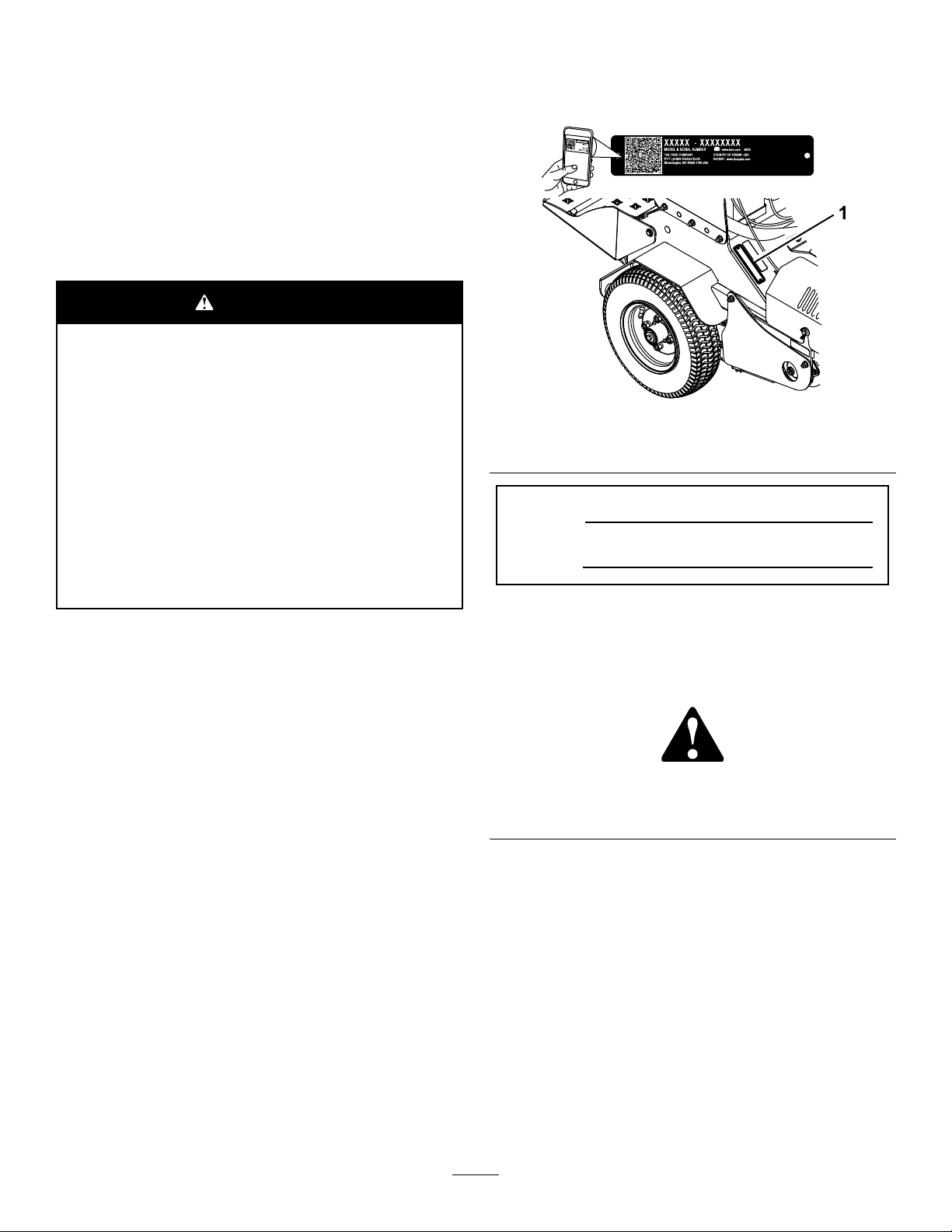
115-4212
1.Hydraulic-uidlevel
2.ReadtheOperator's
Manual.
3.Warning—donottouchthe
hotsurface.
117-2718
120-9570
1.Warning—stayawayfrommovingparts;keepallguards
andshieldsinplace.
decal115-4212
decal121-6150
121-6150
1.Cuttinghazardofhandandfoot—stayawayfrommoving
parts.
decal117-2718
decal121-6161
121-6161
1.Entanglementhazard,belt—stayawayfrommovingparts;
keepallguardsinplace.
decal120-9570
7
Page 8
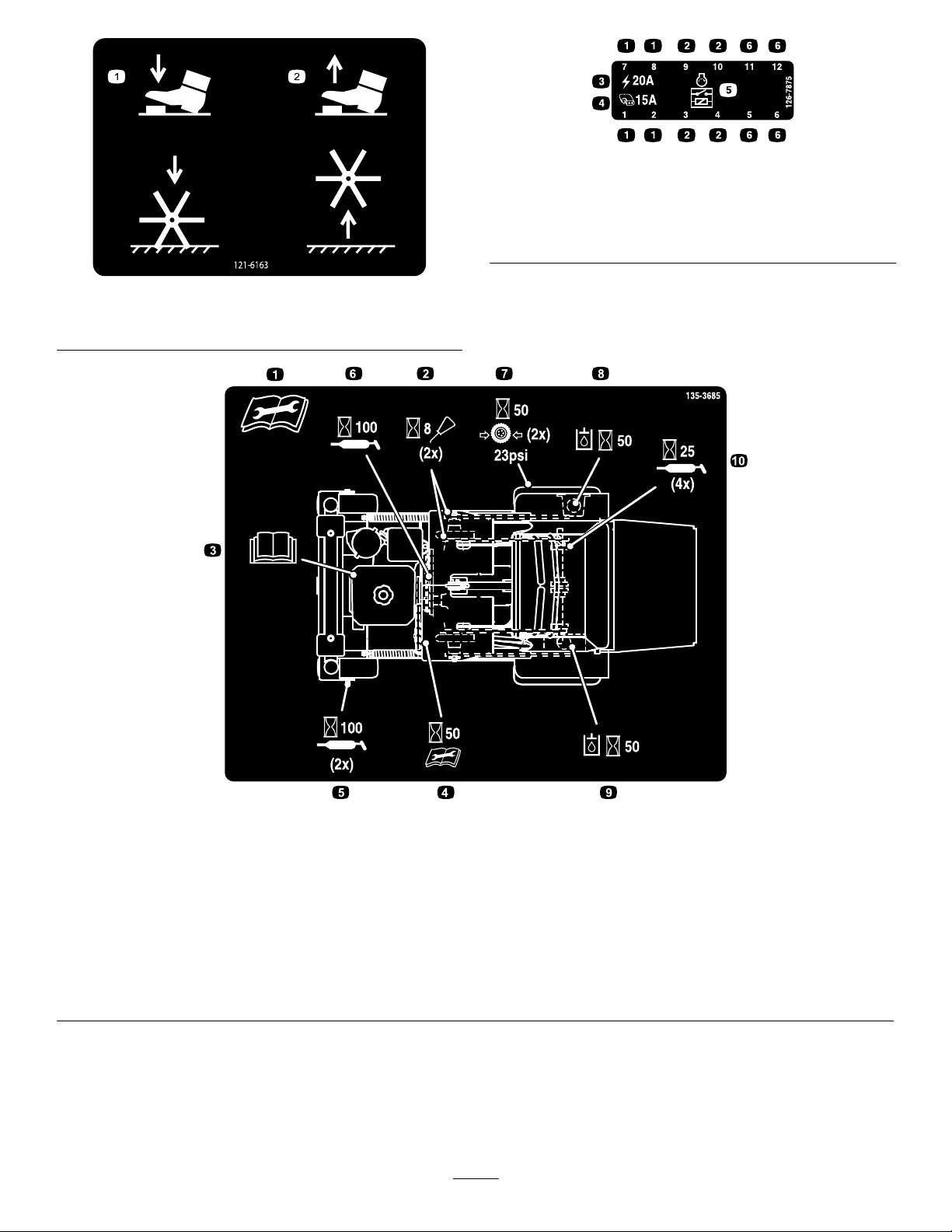
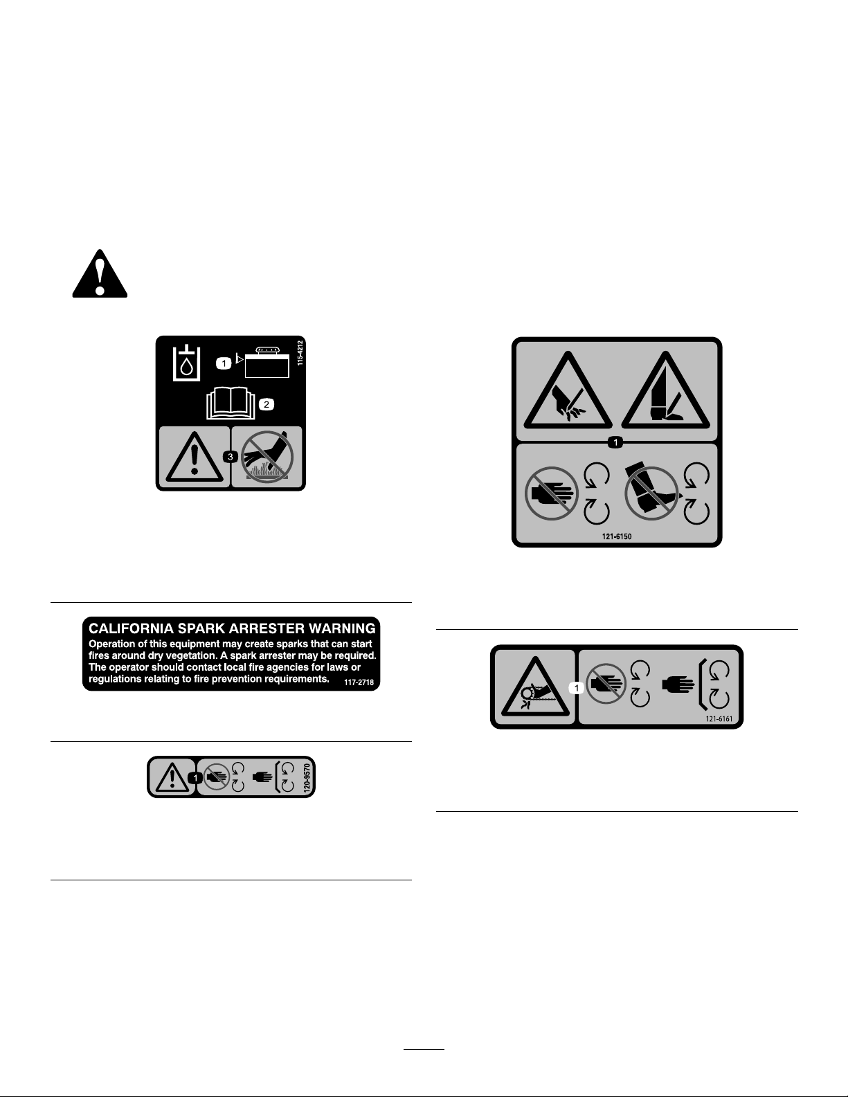
decal126-7875
126-7875
121-6163
1.Presstolowerthetines.2.Releasetoraisethetines.
1.Fuselocation
2.Relaylocation
3.Main(20A)
decal121-6163
4.Auxiliary(15A)
5.Startrelay
6.Notused
135-3685
1.ReadandunderstandtheOperator’sManualbeforeservicing
thismachine.
2.Cleanandoilthechainsandcheckthechaintensiontwice
every8hours
3.Seetheengineowner’smanualforservice8.Checkthehydraulicoilleveltwice(Useonlyrecommended
4.Checktheauxiliarypumpdrivebelttensionevery50hours9.Checktheauxiliaryhydraulictank(UseonlyAW-32hydraulic
5.Greasethefrontcasterwheelbearingstwiceevery100hours10.Greasethetineshaftbearings4timesevery25hours
6.Greasethebeltidlerpivotevery100hours
7.Checkthetirepressure-23psitwiceevery50hours
hydraulicuid)every50hours
uid)every50hours
8
decal135-3685
Page 9
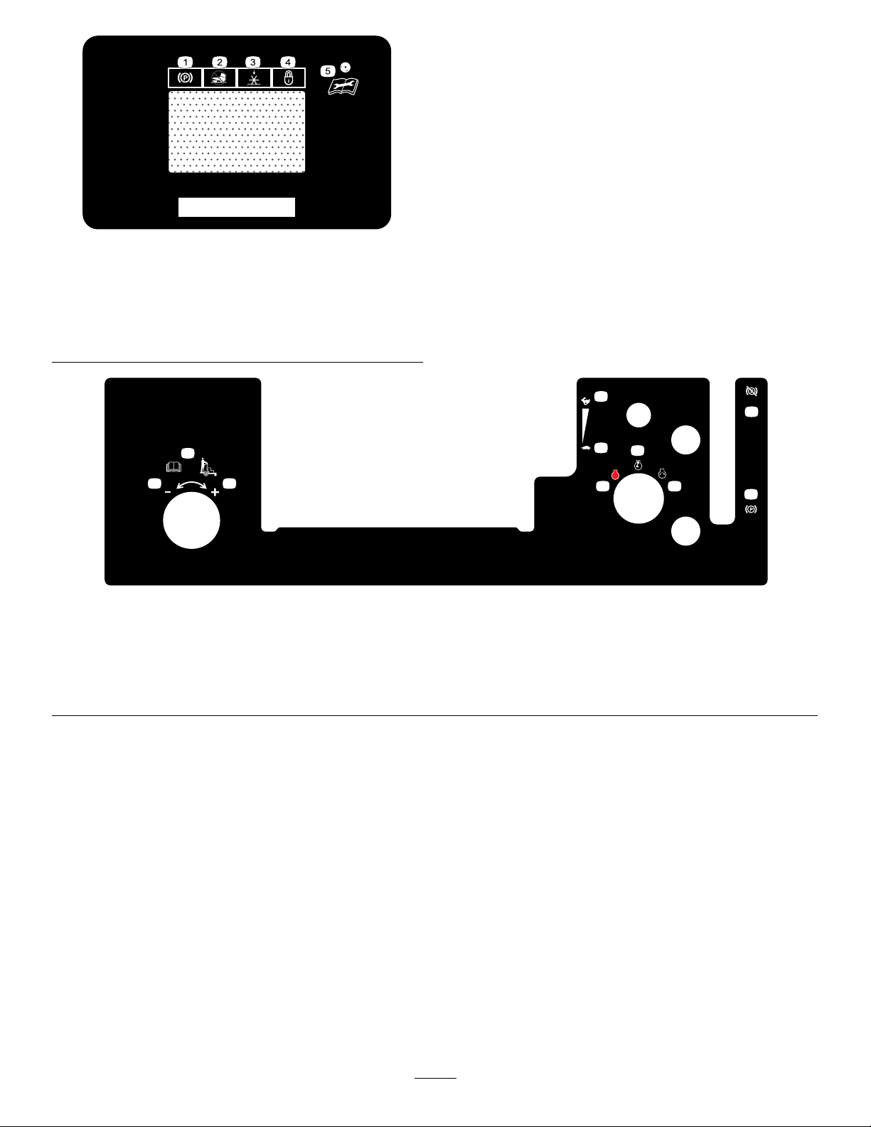
135-1854
STOP
LB
KG
135-2013
2
1
3
4
5
6
7
8
9
10
1.Parkingbrake4.Depthsetting—lock
2.Tineengagementlockout
switch
3.Tines—down
decal135-1854
5.ReadtheOperator’s
Manualbeforeperforming
maintenance.
decal135-2013-1
135-2013
1.Operatorweightadjustment
5.Throttle—slow9.Parkingbrake—engage
2.Increase6.Engine—on10.Parkingbrake—release
3.Decrease7.Engine—start
4.Throttle—fast8.Engine—off
9
Page 10
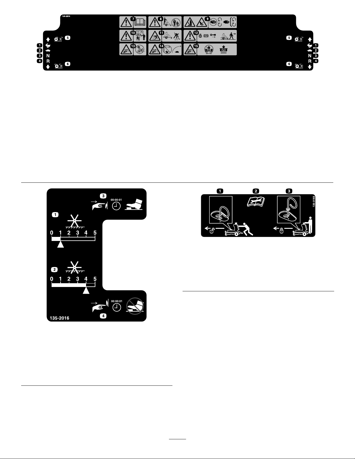
decal135-2014b
135-2014
1.Fast6.Wheelsandtinesrotatewhenmoving
backward
11.Thrownobjecthazard—pickupdebris
beforeoperatingthemachine.
2.Slow7.Warning—readtheOperator’sManual.12.Warning—shutofftheengine,engage
theparkingbreak,andremovethe
ignitionkeybeforeleavingthemachine.
3.Neutral
8.Warning—keepbystandersasafe
distanceawayfromthemachine.
4.Reverse
9.Warning—Cutting/dismemberment
hazardofhandorfoot;tines—stay
awayfrommovingparts;keepall
13.Tippinghazard–Donotoperatethe
machineneardrop-offs.
14.Tippinghazard–Donotturnsharply
whiletravelingfast;slowdownandturn
gradually.
guardsinplace.
5.Wheelsandtinesrotatewhenmoving
forward
10.Warning—Donotoperatethemachine
unlessyouaretrained.
15.Tippinghazard–Donotusesplitramps;
usefullwidthrampstoloadamachine
fortransport.
135-3183
1.Bypassleverpositionfor
pushingthemachine.
2.Readtheinstructions
beforeservicingor
performingmaintenance.
3.Bypassleverpositionfor
operatingthemachine.
decal135-3183
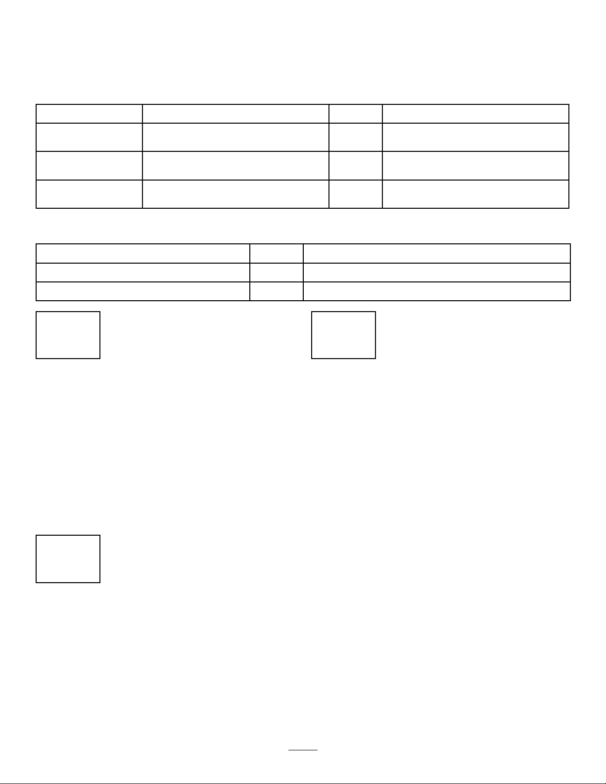
135-2016
1.Electronictinedepth-decrease
2.Electronictinedepth-increase
3.Pressandhold1secondtoturnon—tineground
engagementfootswitchunlock
4.Pressandhold1secondtoturnoff—tineground
engagementfootswitchlock
decal135-2016
10
Page 11
Setup
LooseParts
Usethechartbelowtoverifythatallpartshavebeenshipped.
ProcedureDescription
3
4
5
MediaandAdditionalParts
Description
Operator'sManual
Key2
Nopartsrequired
Nopartsrequired
Nopartsrequired
1
CheckingTireAirPressure
NoPartsRequired
Qty.
Qty.
–
–
–
1
Readbeforeoperatingthemachine.
Startthemachine.
Checkthebatterycharge.
Checkingthetransmissionuid.
Checktheauxiliaryhydraulicuidlevel.
Use
Use
3
CheckingtheBattery Charge
Procedure
Checktheairpressureinthedrivetires,andadjust
thepressureasneeded;refertoCheckingtheDrive
TireAirPressure(page36).
Note:Youdonotadjustairpressureforthe
semi-pneumaticcastertires.
2
ServicingtheEngineOil
NoPartsRequired
Procedure
Theengineisshippedwithoil;checktheengine-oil
leveland,ifnecessary,addoiltothespeciedlevel;
refertoEngine-OilSpecication(page30)and
CheckingtheEngine-OilLevel(page31).
NoPartsRequired
Procedure
Themachineisshippedwithalled,lead-acidbattery ,
Checkthechargeofthebatteryand,ifnecessary ,
chargeit;refertoChargingtheBattery(page35).
11
Page 12

4
CheckingtheTransmission Fluid
NoPartsRequired
Procedure
Thetransmissionisshippedwithtransmissionuid.
Checkthetransmissionuidleveland,ifnecessary,
adduidtothespeciedlevel;refertoTransmission
FluidSpecication(page39)andCheckingthe
TransmissionFluidLevel(page40).
5
ChecktheAuxiliary HydraulicFluidLevel
NoPartsRequired
Procedure
Theauxiliaryhydraulicreservoirisshippedwith
hydraulicuid.Checkthehydraulicreservoiruid
leveland,ifnecessary,adduidtothespeciedlevel;
refertoAuxiliaryHydraulicFluidSpecication(page
39)CheckingtheAuxiliaryHydraulicFluidLevel(page
39).
12
Page 13
ProductOverview
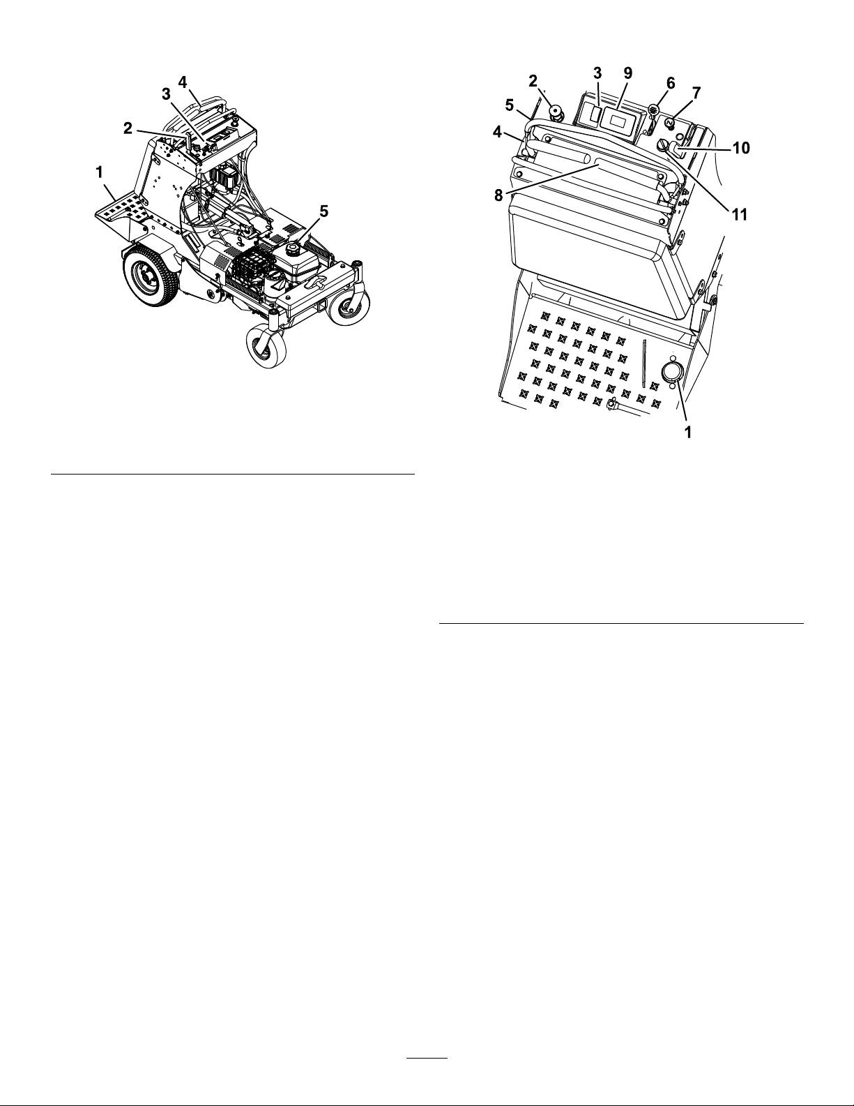
g232039
Figure3
Controls
1.Platform
2.Parkingbrakelever5.Fuelcap
3.Enginecontrols
4.Motion-controllevers
Figure4
1.Tinegroundengagement
footswitch
2.Operatorweight
adjustmentcontrol
3.Multi-functionswitch
4.Leftmotion-controllever
5.Frontreferencebar
6.Throttle
7.Choke
8.Rightmotion-controllever
9.Hourmeter
10.Parking-brakehandle
11.Ignitionswitch
Motion-ControlLevers
Themotion-controlleversarelocatedoneachsideof
thetopconsoleandcontroltheforwardandreverse
motionofthemachine.
Movetheleversforwardorbackwardtocontrolthe
drivewheelonthesamesideforwardorreverse
respectively.Thewheelspeedisproportionaltothe
amountyoumovethelever.
g223341
Important:Thetinesrotatewhenthe
motion-controlleversaremovedoutofthe
NEUTRALposition.
13
Page 14
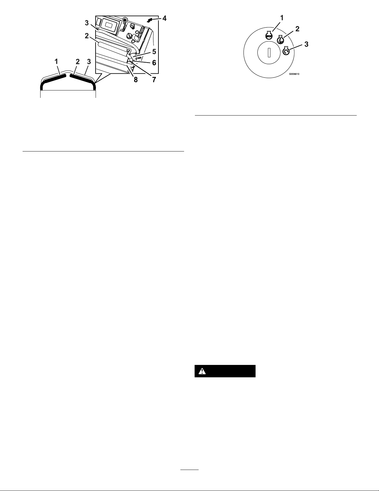
Figure6
g008610
Figure5
1.Leftmotion-controllever
2.Rightmotion-controllever6.Neutral
3.Frontreferencebar
4.Frontofmachine8.Rearreferencebar
5.Forward
7.Reverse
ThrottleLever
Thethrottlelever(Figure4)islocatedonthecontrol
console(redlever).
Usethethrottlelevertocontrolenginespeed.Move
thethrottleleverforwardtoincreaseenginespeed;
movingthethrottleleverrearwardtodecreasethe
enginespeed.
Note:Movethethrottleleverforwardintothedetent
forfullthrottle.
ChokeControl
Thechokecontrol(Figure4)islocatedonthecontrol
console.
Usethechokecontroltoaidinstartingacoldengine.
PulloutthechokecontroltosetthechoketotheON
position;pressinthechokelevertoreducethechoke.
g223330
1.OFF3.START
2.ON
Parking-BrakeHandle
Theparking-brakehandleislocatedonthecontrol
console,totherightofthekeyswitch(Figure4).
Note:Thebrakehandleengagesaparkingbrakein
eachofthetransmissions.
•T oengagetheparkingbrake,pullthehandleback
towardyou.
•T oreleasetheparkingbrake,pushthehandleall
thewayforwardawayfromyou.
Whenparkingonaslope,chockorblockthewheels
inadditiontoengagingtheparkingbrake.Tiedown
themachineandengagetheparkingbrakewhen
transportingthemachine.
Fuel-ShutoffLever
Locatedundertheaircleaneronthefrontrightside.
Thefuel-shutoffleverisusedtoshutoffthefuelwhen
youwillnotusethemachineforafewdays,whileyou
aretransportingthemachinetoandfromthejobsite,
andwhenthemachineisparkedinsideabuilding.
Note:Pulloutthechokecontroltosetthechoketo
theONposition.
Note:Donotrunawarmenginewiththechokein
theONposition.
IgnitionSwitch
TheIgnitionswitchislocatedontherightsideofthe
controlconsole(Figure4).
UsetheIgnitionkeytostartandshutofftheengine.
Theswitchhas3positions:OFF,ON,andSTART
(Figure6).
Rotatethehandlecounterclockwisetoopen;rotate
clockwiseto90°toclose.
Drive-WheelReleaseValves
WARNING
Handsmaybecomeentangledintherotating
drivecomponentsbetweentheengineand
transaxles,whichcouldresultinserious
injuryordeath.
Shutofftheengine,removethekey,andallow
allthemovingpartstostopbeforeaccessing
thedrive-wheelreleasevalves.
14
Page 15
WARNING
Theengineandhydraulicdriveunitscan
becomeveryhot.Touchingahotengineor
hydraulicdriveunitscancausesevereburns.
Allowtheengineandhydraulicdriveunits
tocoolcompletelybeforeaccessingthe
drive-wheelreleasevalves.
Locatedontheleftandrightsidesabovethe
transaxles.
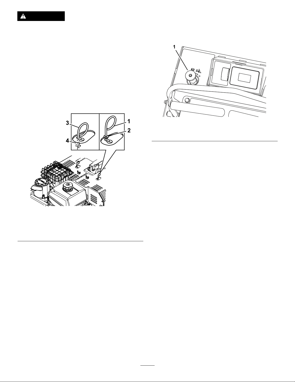
Duringnormaloperatingconditions,thewasheron
theleverispositionedoutsidetheslots.Ifyoumust
pushthemachinebyhand,thevalvesmustbeinthe
releasedposition(seeFigure7).
OperatorWeightAdjustment
Control
Theoperatorweightadjustmentvalveislocatedatthe
leftsideofthecontrolconsole(Figure8).
g249578
Figure8
1.Operatorweightadjustmentcontrol
Usetheoperatorweightadjustmentvalvetohelp
compensatefortheweightoftheoperatorsothatthe
machineachievesthecorrectaeratingpressure,plug
length,andtohelpmaximizelateralmachinestability.
Figure7
1.Leverpositionfor
operatingthemachine
2.Washeroutsideofslot
Toreleasethedrivewheels,movethelevertothe
largeropeningoftheslot,pushitinuntilthewasher
isinsidetheframe,thenmovetheleverbacktothe
narrowportionoftheslot.Repeatthisoneachside
ofthemachine.
Releasetheparkingbrake.Y oucannowpushthe
machinebyhand.
Donottowthemachine.
Toresetthedrivesystembacktotheoperating
position,movethelevertothelargeropeningofthe
slot,pulloutwarduntilthewasherisoutsideofthe
frame,thenmovetheleverbacktothenarrowportion
oftheslotoneachsideofthemachine.
3.Leverpositiontopushthe
machine
4.Washerinsideslot
Note:Eachoperatormustadjustthesystempressure
sothatthedrivetireslightlytouchtheground.
Important:Keepthedrivetiresonthegroundat
alltimestomaximizelateralmachinestability.
g211754
Tine-PressureControl
Thetine-pressurecontrolislocatedontheleftsideof
thecontrolconsole(Figure4).
Usethetine-pressurecontroltoadjustthedownward
pressureonthetinesandcoredepth.Rotatethe
controlcounterclockwisetodecreasethepressure
andthelengthoftheaerationplug;rotateitclockwise
toincreasethepressureandincreasethelengthof
theaerationplug.
TineGroundEngagementFoot
Switch
Keepyourhandsandfeetawayfromthe
tines.Ensurethatthetinesareaisclearofany
obstructionsbeforeloweringit.
Theswitchislocatedontheoperatorplatform.
Tolowerthetinesintotheground,standonthe
tinegroundengagementswitch.T oraisethetines,
removeyourfootfromtheswitch.
Thisswitchcanbelockedout(disabled)withthe
multi-functionswitch.
15
Page 16
•T apandholdthebottomoftheswitchtooverride
andlockout(disable)thefootswitch.TheLED
illuminatesinthehourmeter/tineengagement
display.Usethisfeaturewhentransportingthe
aerator.
•T ounlock,tapandholdthetopofthemulti-function
switchuntiltheLEDlightdisappears.
Note:Thelockoutfeatureisengagedeachtimethe
engineisswitchedoff.
Multi-FunctionSwitch
Themulti-functionswitchislocatedtotheleftofthe
hourmeter/tineengagementdisplay.
Thisswitchallowstheoperatortodothefollowing:
Note:TheLCDindicatorappearsintheparking
brakesettingwhenitmeetsthesafetostartmode
(parkingbrakeengaged).
•Thetineengagementdisplaymonitorsand
displaystheelectronictinedepthsetting.
•increaseordecreasethedepthofaerationplug
•lockorunlockthetinedepthsetting
•resetmaintenanceservicereminderscreens
SmartController/ElectronicDepth
Control
HourMeter/TineEngagementDisplay
Locatedtotheleftoftheignitionswitchonthecontrol
console.
•Thehourmetermonitorsanddisplaysengine
hours.
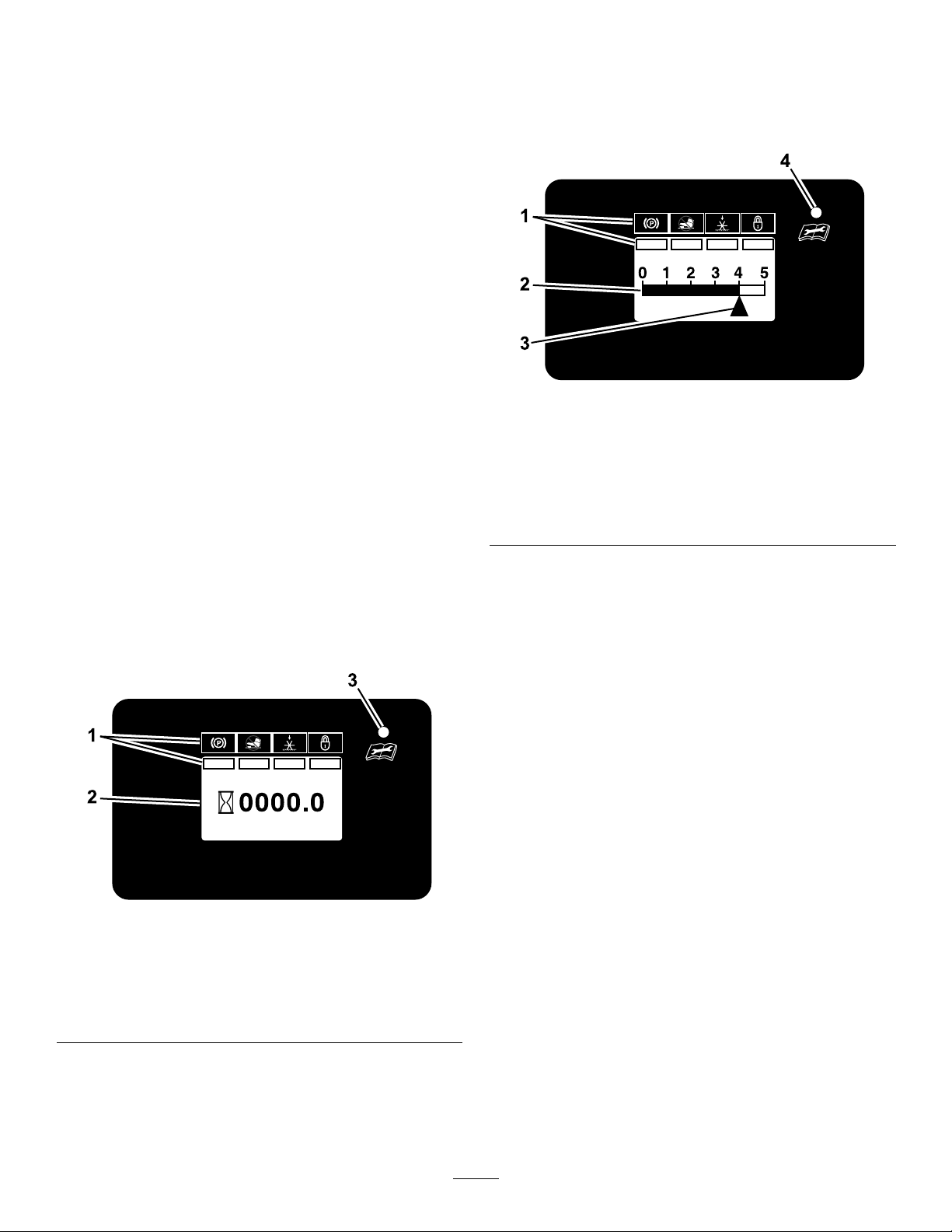
g211731
Figure10
TineEngagementDisplay
1.LCDIndicators/Informationscreen
2.Tinedepthstatusbar
3.Tinedepthsettingindicator
4.LEDstatuslight
Therearetwowaystoactivatethedisplay.
1.T apthemulti-functionswitcheitherupordown
todisplaythetineengagementmeter.
2.Steponthetinegroundengagementfootswitch.
Ahighernumberonthestatusbarincreasesthe
lengthoftheaerationplugandalowernumber
decreasesit.
Note:Ifthepluglengthisnotthedesiredlength,you
mayneedtoadjustthemachinetoaccommodate
foryourweight;refertotheAdjustingtheOperator
WeightControlV alve(page22).
Figure9
HourMeterDisplay
1.LCDIndicators/Informationscreen
2.Hourdisplay
3.LEDstatuslight
Hoursaredisplayedwhenthekeyisofforwhen
themachineisrunning.Hoursarenotdisplayed
whenthemachineisaerating.
LEDStatusLights
Locatedontherightsideofthehourmeter/tine
g211730
engagementdisplay.
TheLEDismulti-coloredtoindicatethesystemstatus
andislocatedontherightsideofthepanel.
•SolidGreen—indicatesnormaloperatingactivity
•BlinkingRed—indicatesthatafaultisactive
•SolidRed—indicatesthatmaintenanceis
required
16
Page 17

ScreenIcons
Start-upScreens
Theinformationscreenusesthefollowingicons:
AeratingHoursParkingbrake
BatteryVoltageEngineOilMaintenance
HourMeter
TransmissionOil
Maintenance
WhenthekeyisswitchedfromOFFtoRUNposition,
thefollowingscreensdisplayfor2seconds.TheLED
statuslightchangesfromredtoorangetogreen.
Therstscreendisplaysthermwareversion.
g212116
Figure11
Thesecondscreendisplaystheaerationhourstothe
tenthofanhour.
VoltageErrorValveSolenoidError
ValveSolenoidConnection
Error
g212114
Figure12
Thethirdscreendisplaysthebatteryvoltagetothe
tenthofavolt.
g212115
Figure13
Thefourthscreendisplaysthehoursuntiltheengine
oilmaintenanceisrequired.Iftheserviceisnot
performed,thetimeisrecordedasnegativehoursto
indicatethenumberofhourspastduefortheservice
(upto-500hours).
17
Page 18

Figure14
Thenalscreendisplayedisthehoursuntil
transmissionoilmaintenanceisrequired.Ifthe
serviceisnotperformed,thetimeisrecordedas
negativehourstoindicatethenumberofhourspast
duefortheservice(upto-500hours).
enginehoursandthencountsdownfrom100
hoursforeachserviceintervalthereafter.
g212117
g030960
Figure16
2.ServiceTransmission
Thetransmissionoilmaintenancereminder
countsdownfromtheinitialbreak-inservice
intervalof250enginehoursandthencounts
downfrom500hoursforeachserviceinterval
thereafter.
Figure15
MaintenanceReminderScreens
Thehourmeterdisplaysthenumberofengine
hoursuntileithertheengineoilortransmissionoil
maintenanceisdue.Thereminderashesandthe
LEDdisplaysasteadyredlight.
Analertoccurswhenthehourcounterreacheszero.
Iftheserviceisnotperformed,thetimeisrecorded
asnegativehourstoindicatethenumberofhours
pastduefortheservice(upto-500hours)(reference
Figure16andFigure17).Thehourmeterswitches
betweenthedefaultscreenandtheactivealert
screen.Ifmorethan1alertisactive,thedisplay
cyclesbetweenthealertsintheorderthatthey
occurredbeforecyclingbacktothedefaultscreen.
Thealertsonlydisplaywhenthedefaultscreenhas
beenactivefor2seconds;howeverifthekeyismoved
totheSTARTposition,thealertsoccurimmediately.
Whenthemachineisaerating,thealertscreendoes
notdisplaybuttheLEDstatuslightremainsasteady
red.
Therearetwomaintenancereminders:
1.ServiceEngine
Theengine-oilserviceremindercountsdown
fromtheinitialbreak-inserviceintervalof5
g212118
g030965
Figure17
Youcanresetmaintenanceremindersmanually.
•Y oucanentertheengineservicereminderreset
modebycyclingthekeyswitchbetweentheRUN
positionandtheOFFposition4timeswithin8
secondswiththeparkingbrakeengaged.
WhentheServiceEnginescreendisplays
andashes,youcanresettheengine-oil
maintenancereminderbypressingthedownon
themulti-functionswitch.Oncethereminder
resets,thescreenexitstheServiceEngine
screenandreturnstothedefaultscreen.
YoucanexittheServiceEnginescreenatany
timebyturningthekeytoeithertheOFForthe
STARTposition.
•Y oucanenterthetransmission-oilmaintenance
reminderresetmodebycyclingthekeyswitch
fromtheRUNpositiontotheOFFpositionandback
totheRUNposition,6timeswithin8seconds,with
theparkingbrakeengaged.
WhentheServiceTransmissionscreendisplays
andashes,youcanresetthetransmission-oil
18
Page 19

maintenancereminderbypressingdownonthe
multi-functionswitch.
YoucanexittheServiceEnginescreenatany
timebyturningthekeytoeithertheOFForthe
STARTposition.
AlertsandErrorMessages
Thesystemiscapableofdisplayingthefollowing
errors:
•VoltageError
ThisoccurswhentheKey-Runvoltageislessthan
12.3orgreaterthan16,avoltageerrorashes.
TheLEDashesaredlight.
Figure18
•ValveSolenoidOpenError
•ValveSolenoidOvercurrentError
Ifanovercurrenteventoccurs,thenumber2
displaysinthelowerleftcornerofthescreen.
Checkthevalvesolenoidandinspectitfordamage
andwear.TheLEDashesaredlight.
g030972
Figure20
1.Number2displays
•ValveSolenoidConnectionError
ThesystemdisplaystheValveSolenoid
ConnectionErroralertandtheLEDashesred
whenthesystemdetectsanerror.Ifthevalve
g030966
solenoidsareconnectedincorrectly(i.e.the
connectorforthereliefvalveisconnectedtothe
othervalvesolenoid)thetinesdonotoperateuntil
thefaultiscorrected.
Ifeither1ofthe2valvesolenoidsdisconnect,the
number6displaysinthelowerleftcornerofthe
screen.TheLEDashesaredlight.
Figure19
1.Number6displays
g030977
Figure21
g030971
19
Page 20

Specications
Height
Length
Width
RPM(FullSpeed)3800±100rpm(noload)
Aerationwidth
Coringrange1.3to12.7cm(0.5to5inches)
Holespersquarefoot
Tines36
Weight
AselectionofT oroapprovedattachmentsand
accessoriesisavailableforusewiththemachine
toenhanceandexpanditscapabilities.Contact
yourAuthorizedServiceDealerorauthorizedT oro
distributororgotowww.Toro.comforalistofall
approvedattachmentsandaccessories.
Toensureoptimumperformanceandcontinuedsafety
certicationofthemachine,useonlygenuineT oro
replacementpartsandaccessories.Replacement
partsandaccessoriesmadebyothermanufacturers
couldbedangerous,andsuchusecouldvoidthe
productwarranty.
129.5cm(51inches)
173.2cm(68.6inches)
90.2cm(35.5inches)
61cm(24inches)
4.6
388kg(856lb)
Operation
Note:Determinetheleftandrightsidesofthe
machinefromthenormaloperatingposition.
AddingFuel
DANGER
Incertainconditions,fuelisextremely
ammableandhighlyexplosive.Areor
explosionfromfuelcanburnyouandothers
andcandamageproperty.
•Fillthefueltankoutdoors,inanopenarea,
andwhentheengineiscold.Wipeupany
fuelthatspills.
•Donotllthefueltankcompletelyfull.
Addfueltothefueltankuntilthelevelis6
to13mm(1/4to1/2inch)belowthebottom
ofthellerneck.Thisemptyspaceinthe
tankallowsthefueltoexpand.
•Neversmokewhenhandlingfuel,andstay
awayfromanopenameorwhereaspark
mayignitethefuelfumes.
•Storefuelinanapprovedfuelcontainer
andkeepitoutofthereachofchildren.
•Neverbuymorethana30-daysupplyof
fuel.
WARNING
Fuelisharmfulorfatalifswallowed.
Long-termexposuretovaporscancause
seriousinjuryandillness.
•Avoidprolongedbreathingofvapors.
•Keepyourfaceawayfromthenozzleand
fueltankorconditionerbottleopening.
•Avoidcontactwithskin;washoffspills
withsoapandwater.
20
Page 21

FuelSpecication
Petroleum
fuel
Ethanol
blended
fuel
Important:Forbestresults,useonlyclean,fresh
fuel(lessthan30daysold).
•Donotusegasolinecontainingmethanol.
•Donotstorefueleitherinthefueltankorfuel
containersoverthewinterunlessyouuseafuel
stabilizer.
•Donotaddoiltogasoline.
Useunleadedgasolinewithanoctaneratingof87
orhigher((R+M)/2ratingmethod).
Useanunleaded-gasolineblendwithupto10%
ethanol(gasohol)or15%MTBE(methyltertiary
butylether)byvolumeisacceptable.Ethanoland
MTBEarenotthesame.
Gasolinewith15%ethanol(E15)byvolumeis
notapprovedforuse.Neverusegasolinethat
containsmorethan10%ethanolbyvolume,such
asE15(contains15%ethanol),E20(contains
20%ethanol),orE85(containsupto85%
ethanol).Usingunapprovedgasolinemaycause
performanceproblemsand/orenginedamage
whichmaynotbecoveredunderwarranty.
UsingStabilizer/Conditioner
OpeningandClosingthe FuelShutoffValve
Controlfuelowtotheenginewiththefuelshutoff
valveasfollows:
•T oopenthefuel-shutoffvalve,fullyrotatethe
handleforthevalveleft.
•T oclosethefuel-shutoffvalve,fullyrotatethe
handleofthevalveright.
Figure22
1.Fueltank
2.Fuel-shutoffvalve(open
position)
3.Fuel-shutoffvalve(closed
position)
g249775
Usefuelstabilizer/conditionerinthemachineatall
timestokeepthefuelfreshlongerwhenusedas
directedbythefuel-stabilizermanufacturer.
Important:Donotusefueladditivescontaining
methanolorethanol.
Addtheamountoffuelstabilizer/conditionertofresh
fuelasdirectedbythefuel-stabilizermanufacturer.
FuelingtheMachine
Fuel-tankcapacity:7L(1.9USgallons)
1.Cleanaroundthefuel-tankcap.
2.Removethecapfromthetank.
3.Fillthefueltankwithfueltowithin6to13mm
(1/4to1/2inch)fromthetopofthetank.Donot
llintothellerneck.
Important:Donotllthetankmorethan
6mm(1/4inch)fromthetopofthetank
becausethefuelmusthaveroomtoexpand.
4.Installthefuel-tankcapandwipeupanyspilled
fuel.
StartingtheEngine
1.Leavethemotion-controlleversinneutraland
engagetheparkingbrake.
2.PlacethethrottlemidwaybetweentheSLOW
andFASTpositions.
3.Onacoldengine,pushthechokeleverforward
intotheONposition.Onawarmengine,leave
thechokeintheOFFposition.
4.TurnignitionswitchtotheSTARTposition.
Releasetheswitchassoonastheenginestarts.
Important:Donotcranktheengine
continuouslyformorethan10secondsat
atime.Iftheenginedoesnotstart,allow
a60-secondcool-downperiodbetween
startingattempts.Failuretofollowthese
guidelinescanburnoutthestartermotor
5.IfthechokeisintheONposition,gradually
returnchoketotheOFFpositionastheengine
warmsup.
21
Page 22

CheckingtheSafety Interlock
Important:Ensurethattheoperatorsafety
mechanismsareconnectedandarefullyfunction
priortouse.
Note:Ifthemachinedoesnotpasseitherofthetests
thatfollow,Donotoperatethemachine.Contact
yourauthorizedT orodistributor.
CheckingtheEngineStarting Circuit
Note:Thestateparkingbrakeinterlockyouare
checkingisshowninbold.
EngagetheparkingbrakeThestarterrotates
CheckParkingBrakeInterlock
switchforyourcomfort.T oadjustit,loosenthe
footrockerbarhardware,slidethebarforward
orrearward,andtightenthehardware.
ChangingtheTineDepth Setting
1.Stopthemachineandengagetheparkingbrake.
2.Pressthemulti-functionswitchtoactivatethe
display.
3.CyclethekeyswitchbetweentheRUNposition
andtheOFFposition5times.Thetinedepth
settingindicator(triangle)onthedisplaywill
begintoash.
4.T apthemulti-functionswitchupordownto
settheaerationdepth.T apthebottomofthe
multi-functionswitchtolowerthetinedepthto
removealongerplug.Tapthetopoftheswitch
toraisethetinedepthtoremoveashorterplug.
Note:Theidealplugdepthis2.5to3inches(6.4
to7.6cm).Adjustthecontrolstoadapttothesoil
conditions.
Note:Thestateparkingbrakeinterlockyouare
checkingisshowninbold.
DisengagetheparkingbrakeThestartershouldnot
rotate
LoweringtheTines
DANGER
Therotatingtinesundertheenginedeckare
dangerous.Tinecontactcancauseserious
injuryorkillyou.
Donotputhandsorfeetunderthemachine
whentheengineisrunning.
1.SetthrottletotheFASTposition.
2.T aptheswitchoncetodisplaythetine
engagementdepthsetting;adjustifnecessary.
3.Lowerthetinesbypressingonthetineground
engagementfootswitch.
4.Standontheswitchandmovethemotion-control
leversforwardtoaerate.
Locking/UnlockingtheTine DepthSetting
Thesettingscanbelockedorleftunlocked.
•T olockthesetting,Turntheignitionkeyfromthe
OFFtotheONposition5times.TheLEDstatus
lightilluminatesinthetineengagementdisplay
(referenceFigure10).
•T ounlockthesetting,pressandholdthebottom
oftheswitchfor1second.TheLEDstatuslight
turnsoff.
SwitchthekeytotheOFForSTARTpositionwhenyou
arenished.
AdjustingtheOperator WeightControlValve
Note:Adjustthesystempressuresothatthedrive
tireslightlytouchtheground.
Important:Keepthedrivetiresonthegroundat
alltimestomaximizelateralmachinestability.
1.Raisethetines,drivetheaeratortoahard,at
turfsurface,andstoptheaerator,butleavethe
enginerunning.
2.Standontheoperator’splatform.
Note:Youcanadjustthefootrockerbar,
locatedbehindthetinegroundengagementfoot
3.Pressthetinegroundengagementfootswitch
tolowerthetines.
22
Page 23

•Ifthemachineraisesandthegroundtires
arenolongertouching,rotatetheknob
fortheoperatorweightadjustmentcontrol
counterclockwise(Figure23)tolowerthe
machineuntilthetirestouchtheground.
•Ifthetinesarenottouchingtheground,
rotatetheknobcontrolclockwiseuntilthe
tineslowerandtouchtheground(butnot
raisethemachine).
Figure23
1.Knob(operatorweightadjustmentcontrol)
Important:Keepthedrivetiresonthe
groundatalltimestomaximizelateral
machinestability.
4.Releasethetinegroundengagementfootswitch
toraisethetines.
5.Whileholdingthepositionoftheknobforthe
weightcontrolvalve,tightenthejamnut.
Note:Ifyouarehavingdifcultymaintainthe
valveadjustmentwhiletighteningthejamnut,
useahexkeyintheshaftoftheweightcontrol
valve.
3.Activatethetineengagementfootswitchlockout.
4.PlacethethrottlemidwaybetweentheSLOW
andFASTpositions.
5.Allowtheenginetorunforaminimumof15
seconds,thenturntheignitionswitchtotheOFF
positiontoshutofftheengine.
6.Engagetheparkingbrake.
7.Removethekeytopreventchildrenorother
unauthorizedpersonsfromstartingtheengine.
8.Closethefuel-shutoffvalvewhenyouwillnot
usethemachineforafewdays,whenyouare
transportingthemachine,orwhenthemachine
isparkedinsideabuilding.
DrivingtheMachine
CAUTION
Machinecanspinveryrapidlybypositioning
g249872
onelevertoomuchaheadoftheother.
Operatormaylosecontrolofthemachine,
whichmaycausedamagetothemachineor
injury.
•Usecautionwhenmakingturns.
•Slowthemachinedownbeforemaking
sharpturns.
Important:Tobeginmovement(forwardor
backward),thebrakelevermustbedisengaged
(pushedforward)beforethemotion-controllevers
canbemoved.
RaisingtheTines
1.Removeyourfootfromthetineground
engagementfootswitch
2.TurntheignitionkeyfromtheONpositiontothe
OFFposition.
Important:Thetinesarerotatingwhenthe
motion-controlleverismovedoutoftheneutral
position.
ShuttingOfftheEngine
1.Movethemotion-controlleversbacktothe
neutralpositionandbringthemachinetoafull
stop.
2.Liftyourfootoffofthetinegroundengagement
footswitchcontroltoraisethetines.
Figure24
1.Leftmotion-controllever
2.Rightmotion-controllever6.Neutral
3.Frontreferencebar
4.Frontofmachine8.Rearreferencebar
DrivingForward
1.Ensurethatthemotion-controlleversareinthe
neutralposition.
2.Releasetheparkingbrake.
23
5.Forward
7.Reverse
g223330
Page 24

3.T omoveforwardinastraightline,moveboth
leversforwardwithequalpressure.
g016673
Figure26
Toturnleftorright,releasepressureonthe
motion-controllevertowardthedesiredturn
direction.
Figure25
Toturnleftorright,pullthemotion-controllever
backtowardneutralinthedesiredturndirection.
Thetinescanbeinthedownpositionwhen
makinggradualturns.
Tomakezero-degreeturns,liftyourfootoffthe
tineengagementfootswitchcontroltoraisethe
tines.Theheadwillraisein1second.
Important:Donotmakeazero-degreeturn
whenthetinesaredownasturftearingwill
result.
Important:Donotdriveinreversewhenthe
tinesaredownasturftearingwilloccur.
Themachinemovesfasterthefartherthe
motion-controlleversaremovedfromtheneutral
position.
4.T ostop,positionbothmotion-controlleversin
theneutraloperatingposition.
DrivinginReverse
1.Movethemotion-controlleverstotheneutral
operatingposition.
2.T omoverearwardinastraightline,slowlymove
bothleversrearwardwithequalpressure.
g016672
Tomakezeroturns,liftyourfootoffofthetine
groundengagementfootswitchtoraisethe
tines.Theheadwillraiseinhalfsecond.
Important:Donotmakeazeroturnwhen
thetinesareinthedownposition.
3.T ostop,positionbothmotion-controlleversin
theneutraloperatingposition.
PositioningtheAir-Cleaner CoverforColdorWarmAir Temperature
Important:Runningtheenginewiththe
air-cleanercoverpositionedforcold-weather
operationinnormalconditionscandamagethe
engine.
Theair-cleanercoverhas2positions:thecoldor
normal,ambientairpositions:
Adjusttheair-cleanercoverasfollows:
•Whenoperatinginacoldambientaircondition
(coldairtemperatureandhumidity)—positionthe
air-cleanercoverwithsnowakedecalfacingout
(Figure27).
Note:Usethispositionifyourmachineexhibits
carburetoricing.Symptomsincludetheengine
runsroughatidleorlowspeed,anditdischarges
blackorwhitesmokeintheexhaust.
•Whenoperatinginanormalambientair
condition—positiontheair-cleanercoverwithsun
decalfacingout(Figure27).
Note:Usethispositionifyourmachineisnot
exhibitingcarburetoricing.
24
Page 25

Figure27
1.Normalambientair
position
2.Coldambientairposition
AdjustingtheFront Reference/SpeedControl Bar
Adjustthefrontreference/speedcontrolbarfor
desiredmaximumforwardspeed.
1.Shutofftheengine,engagetheparkingbrake,
andmovethemotioncontrolleverstotheneutral
position.
2.Loosentheboltsonbothsidesofthecontrol
towerbylooseningthetwonutsoneachside
(fourtotal)oftheconsole(seeFigure28).
Important:Makesurethenutsandboltsaretight
sothefrontreference/speedcontrolbardoesnot
moveduringoperation.
LoadingtheMachine
Useextremecautionwhenloadingmachineson
trailersortrucks.Useafull-widthramptoextend
g023827
beyondthereartiresinsteadofindividualrampsfor
eachsideofthemachine.Withtheplatformup,a
full-widthrampprovidesasurfacetowalkonbehind
themachine.
Asteeprampanglemaycausecomponentstoget
caughtasthemachinemovesfromramptotraileror
truck.Steeperanglesmayalsocausethemachineto
tipbackward.Ifloadingonornearaslope,position
thetrailerortrucksothatitisonthedownsideof
theslopeandtherampsextendsuptheslope.This
minimizestherampangle.Thetrailerortruckshould
beaslevelaspossible.
Important:Donotattempttoturnthemachine
whileontheramp,youmaylosecontrolanddrive
offtheside.
Avoidsuddenaccelerationwhendrivinguparamp
andsuddendecelerationwhenbackingdowna
ramp.Bothmaneuverscancausethemachinetotip
backward.
Figure28
1.Twonuts
3.Movethebarforwardtoobtainthefastestspeed.
Movethebarbackwardtoobtaintheslowest
speed.
4.Onbothsides,tightenthenutsandbolts.
2.Frontreference/speed
controlbar
TransportingtheMachine
Useaheavy-dutytrailerortrucktotransportthe
machine.Ensurethatthetrailerortruckhasallthe
necessarylightingandmarkingasrequiredbylaw.
Whenusingatrailer,secureitwiththesafetychains.
1.Loadthemachineontothetransportvehicle.
2.Lockthetinesintheuppositionbytappingand
holdingthemulti-functionswitchinthedown
positionuntiltheLEDindicatorappearsonthe
hourmeter/tineengagementdisplay.
3.Engagetheparkingbrake,shutofftheengine,
andremovethekey.
g231460
4.Closethefuel-shutoffvalve.
5.Blockthewheelsandsecurelybindthemachine
tothetrailerortruckwithstraps,chains,cable,
orropes.Ifpossible,bothfrontandrearstraps
shouldbedirecteddownandoutwardfromthe
machine.
Important:Useonlythe4designated
tie-downlocationsonthemachine—2onthe
leftsideand2ontheright;refertoFigure29.
25
Page 26

Figure29
Leftsideshown
1.Tie-downlocation
CAUTION
Thismachinedoesnothaveproperturn
signals,lights,reectivemarkings,ora
slow-moving-vehicleemblem.Drivingona
streetorroadwaywithoutsuchequipment
isdangerousandcanleadtoaccidents
causingpersonalinjury.Drivingonastreetor
roadwaywithoutsuchequipmentmayalsobe
aviolationofstatelawsandtheoperatormay
besubjecttotrafcticketsand/ornes.
Donotdrivethemachineonapublicstreet
orroadway.
WARNING
g212139
Loadingamachineonatrailerortruck
increasesthepossibilityofbackwardtip-over.
Backwardtip-overcouldcauseseriousinjury
ordeath.
•Useextremecautionwhenoperatinga
machineonaramp.
•Useonlyasingle,full-widthramp;Donot
useindividualrampsforeachsideofthe
machine.
•Avoidsuddenaccelerationordeceleration
whiledrivingmachineupordownaramp
toavoidtippingbackward.
26
Page 27

Maintenance
Downloadafreecopyoftheelectricalorhydraulicschematicbyvisitingwww.Toro.comandsearchingforyour
machinefromtheManualslinkonthehomepage.
CAUTION
Ifyouleavethekeyintheswitch,someonecouldaccidentlystarttheengineandseriously
injureyouorotherbystanders.
Removethekeyfromtheswitchbeforeyouperformanymaintenance.
WARNING
Theenginecanbecomeveryhot.Touchingahotenginecancausesevereburns.
Allowtheenginetocoolcompletelybeforeserviceormakingrepairsaroundtheenginearea.
RecommendedMaintenanceSchedule(s)
MaintenanceService
Interval
Aftertherst5hours
Aftertherst100hours
Beforeeachuseordaily
Every25hours
Every50hours
Every80hours
MaintenanceProcedure
•Changetheengineoil.
•Checkthetransmissionoutputshaftnuttorquespecication.
•Changetheauxiliaryhydraulicreservoirlteranduid.
•Changethehydraulictransmissionlteranduid.
•Lubricatethechains.
•Checktheengine-oillevel.
•Checktheconditionandtensionofthechains.
•Checktheconditionofthesprockets.
•Checkthetines.
•Cleantheengineandtheexhaustsystemarea(moreoftenindryordirtyconditions).
•Cleanthegrassanddebrisbuildupfromthemachine.
•Greasethefrontwheelbearings.
•Greasetineshaftbearings.
•Greasehydrooutputshaftangedbearings.
•Cleanthefoampre-cleaner(morefrequentlyindustyconditions).
•Checksparkarrester(ifequipped).
•Checktheairpressureinthedrivetires.
•Checktheconditionandtensionofthebelts.
•Checkthetransmissionuidlevel.
•Removetheengineshroudsandcleanthecoolingns.
Every100hours
Every160hours
Every200hours
Every250hours
Every300hours
•Changetheengineoil.(moreoftenundersevereconditions.)
•Check,cleanandgapthesparkplug.
•Replacethefoampre-cleaner.
•Changetheauxiliaryhydraulicreservoirlteranduid.
•Changethehydraulictransmissionlteranduid.
•Replacethepaperairlter(morefrequentlyindustyconditions).
Monthly
•Servicethebattery.
27
Page 28

MaintenanceService
Interval
Yearly
MaintenanceProcedure
•Greasebeltidlerpivot.
•Greasefrontcasterhubs.
•Checkthetorqueofthewheelhubbolts.
•Checkthetorqueonthewheellugnuts.
•Checkthetorqueofthetransmissionoutputshaftnut.
Yearlyorbeforestorage
•T ouchupareaswithchippedpaint.
Pre-Maintenance
Procedures
CAUTION
Raisingthemachineforserviceor
maintenancerelyingsolelyonmechanical
orhydraulicjackscouldbedangerous.The
mechanicalorhydraulicjacksmaynotbe
enoughsupportormaymalfunctionallowing
themachinetofall,whichcouldcauseinjury.
Donotrelysolelyonmechanicalorhydraulic
jacksforsupport.Useadequatejackstands
orequivalentsupport.
PreparingforMaintenance
1.Parkthemachineonalevelsurfaceandengage
theparkingbrake.
g023810
Figure30
1.Spark-plugwire
2.Shutofftheengine,removethekey ,andwaitfor
allmovingpartstostop.
3.Allowtheenginetocool.
4.Disconnectthespark-plugwirefromthespark
plugandkeepthewireawayfromtheplug,to
preventaccidentalstarting(Figure30).
28
Page 29

Lubrication
LubricatingtheGrease Fittings
LubricatingtheChains
ServiceInterval:Beforeeachuseordaily
Important:Donotlubricatethechainswith
penetratingoilorsolvents.Useanoilorchain
lubricant.
1.Shutofftheengine,waitforallmovingpartsto
stop,andremovethekey.Engagetheparking
brake.
2.Lifttherearofthemachineandsupportusing
jackstandsorequivalentsupport.
CAUTION
Raisingthemachineforservice
ormaintenancerelyingsolelyon
mechanicalorhydraulicjackscouldbe
dangerous.Themechanicalorhydraulic
jacksmaynotbeenoughsupportormay
malfunctionallowingthemachinetofall,
whichcouldcauseinjury .
Donotrelysolelyonmechanical
orhydraulicjacksforsupport.Use
adequatejackstandsorequivalent
support.
Note:Seethechartbelowforserviceintervals.
1.Shutofftheengine,waitforallmovingpartsto
stop,andremovethekey.Engagetheparking
brake.
2.LubricatethettingswithNLGIgradeNo.2
multi-purposegrease.
Refertothefollowingchartforttinglocations
andlubricationschedule.
LubricationChart
Fitting
Locations
1.FrontWheel
CasterHubs
2.TineShaft
Bearings
3.BeltIdler
Pivot
Initial
Pumps
12Yearly
1425hours
11Yearly
Numberof
Places
Service
Interval
3.Starttheengineandmovethrottlecontrolahead
to1/2throttleposition.Disengagetheparking
brake.
WARNING
Theenginemustberunningandthe
drivewheelsmustbeturningsothat
adjustmentscanbeperformed.Contact
withmovingpartsorhotsurfacesmay
causepersonalinjury.
Keepyourngers,hands,andclothing
clearofrotatingcomponentsandhot
surfaces.
4.Withtheenginerunning,slowlymovethe
motion-controlleversforwardandlubricateall4
chains.
5.Checktheconditionandtensionofthechains;
refertoCheckingtheConditionoftheChains
(page36).
g230394
Figure31
1.Frontwheelcasterhubs3.Beltidlerpivot
2.Tineshaftbearings
29
Page 30

EngineMaintenance
5.Wipedirtawayfromthebaseandthecoverwith
amoistrag.
ServicingtheAirCleaner
ServiceInterval:Every50hours—Cleanthefoam
pre-cleaner(morefrequentlyin
dustyconditions).
Every200hours—Replacethefoam
pre-cleaner.
Every300hours—Replacethepaperairlter
(morefrequentlyindustyconditions).
Important:Donotoperatetheenginewithoutthe
airlterassembly;extremeenginedamagemay
occur.
1.Releasethelatchesonthecoverfortheair
cleaner.
2.Removethecoverandcleanitthoroughly
(Figure32).
Note:Becarefultopreventdirtanddebrisfrom
fallingintothebase.
Note:Becarefultopreventdirtanddebrisfrom
enteringtheairductleadingtothecarburetor.
6.Installthefoampre-cleanerontothepaperair
lter(Figure32).
Note:Useanewpaperairlterifyoudiscarded
theoldone.
7.Installtheairlterassemblytotheair-lterbase
(Figure32).
8.Alignthearrowdecalontheair-cleanercover
andthearrowdecalonthebase(Figure33).
Figure32
1.Air-lterbase4.Cover
2.Paperairlter
3.Foampre-cleaner
3.Removethefoampre-cleaner,washitwitha
milddetergentandwater,andthenblotitdry
(Figure32).
4.Removeandinspectthepaperairlter(Figure
32);discarditifitisexcessivelydirty.
5.Latchontheair-cleaner
cover(2)
g023809
Figure33
1.Alignment-arrowdecal(normalambientairpositionshown)
9.Securetheair-ltercovertothebasewiththe
latches.
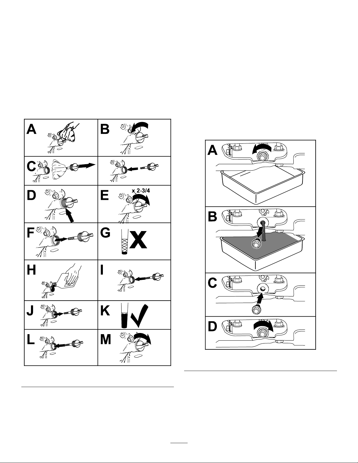
ServicingtheEngineOil
Engine-OilSpecication
OilType:Detergentoil(APIserviceSJorlater)
g023795
EngineOilCapacity:1.7L(1.8USqt)withoutthe
lter;1.5L(1.6USqt)withthelter.
Oilviscosity:Refertothetablebelow.
g023796
Figure34
Important:Donottrytocleanapaperlter.
30
Page 31
CheckingtheEngine-OilLevel
ChangingtheEngineOil
ServiceInterval:Beforeeachuseordaily
Important:Donotoperatetheenginewiththeoil
levelbelowtheLow(orAdd)markonthedipstick,
orovertheFullmark.
1.Movethemachinetoalevelsurface.
2.Shutofftheengine,engagetheparkingbrake,
removethekey,andwaitforallmovingpartsto
stopbeforeleavingtheoperatingposition.
3.Allowtheenginetocool.
4.Checktheengine-oillevelasshowninFigure
35.
ServiceInterval:Aftertherst5hours
Every100hours(moreoftenundersevere
conditions.)
Note:Disposeoftheusedoilatarecyclingcenter.
1.Parkthemachinesothatthedrainsideisslightly
lowerthantheoppositesidetoassuretheoil
drainscompletely.
2.Shutofftheengine,engagetheparkingbrake,
removethekey,andwaitforallmovingpartsto
stopbeforeleavingtheoperatingposition.
3.ChangetheengineoilasshowninFigure36.
Note:T orquedrainplugto18N∙m(13ft-lb).
Figure35
5.Iftheoillevelislow,wipeofftheareaaround
theoilllcap,removecapandaddthespecied
oiluntiltheoillevelisattheFullmarkonthe
dipstick.
Note:Donotoverlltheenginewithoil.
g249685
Figure36
g249636
4.Slowlypourapproximately80%ofthespecied
oilintothellertube,andslowlyaddthe
additionaloiltobringittotheFullmark(Figure
37).
31
Page 32
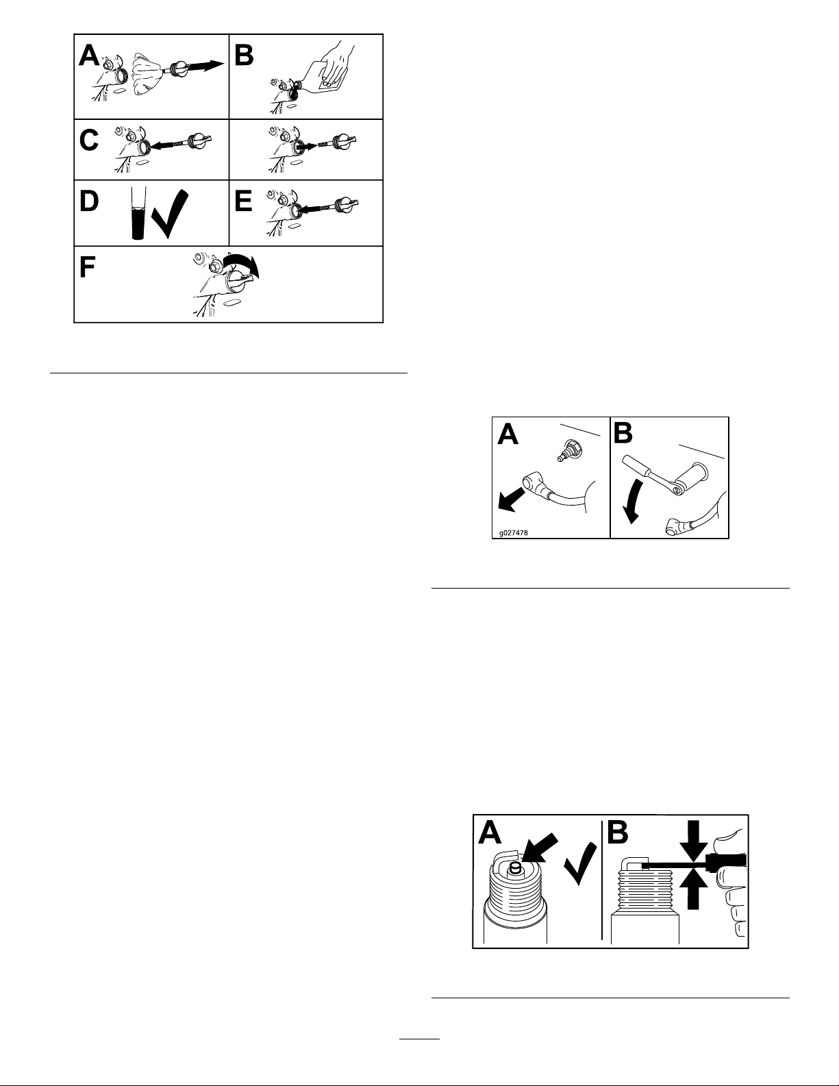
ServicingtheSparkPlug
ServiceInterval:Every160hours
TypeforallEngines:NGKBR6HS,Champion
RTL86C,orequivalent
AirGap:0.76mm(0.030inch)
Ensurethattheairgapbetweenthecenterandside
electrodesiscorrectbeforeinstallingthesparkplug.
Useasparkplugwrenchforremovingandinstalling
thesparkplug(s)andagappingtool/feelergaugeto
checkandadjusttheairgap.Installanewspark
plug(s)ifnecessary.
Figure37
5.Starttheengineanddrivetoaatarea.
6.Checktheengine-oillevel.
g249684
RemovingtheSparkPlug
1.Shutofftheengine,engagetheparkingbrake,
removethekey,andwaitforallmovingpartsto
stopbeforeleavingtheoperatingposition.
2.RemovethesparkplugasshowninFigure38.
g027478
Figure38
CheckingtheSparkPlug
Important:Donotcleanthesparkplug(s).
Alwaysreplacethesparkplug(s)whenithasa
blackcoating,wornelectrodes,anoilylm,or
cracks.
Ifyouseelightbrownorgrayontheinsulator,the
engineisoperatingproperly.Ablackcoatingonthe
insulatorusuallymeanstheaircleanerisdirty .
Setthegapto0.75mm(0.03inch).
Figure39
32
g206628
Page 33

InstallingtheSparkPlug
CheckingtheSpark
Tightenthesparkplug(s)to22N∙m(16ft-lb).
Figure40
Arrester
MachineswithaSparkArrester
Only
ServiceInterval:Every50hours
WARNING
Hotexhaustsystemcomponentsmayignite
fuelvaporsevenaftertheengineisshut
off.Hotparticlesexhaustedduringengine
operationmayigniteammablematerials.
Firemayresultinpersonalinjuryorproperty
damage.
Donotrefuelorrunengineunlessaspark
g027735
arresterisinstalled.
1.Shutofftheengine,engagetheparkingbrake,
removethekey,andwaitforallmovingpartsto
stopbeforeleavingtheoperatingposition.
2.Allowthemufertocool.
3.Checkthesparkarresterforbreaksinthe
screenorwelds.
Note:Replacethesparkarresterifitisworn
ordamaged.
4.Ifyouseethatthescreenisplugged,perform
thefollowing:
A.Removethesparkarrester.
B.Shakeloosetheparticlesfromthearrester
andcleanscreenwithawirebrush.
Note:Soakthearresterscreeninsolvent
ifnecessary.
C.Installsparkarresterontoexhaustoutlet.
33
Page 34

ElectricalSystem
Maintenance
JumpStartingtheMachine
1.Checktheweakbatteryforterminalcorrosion
andcleanitpriortojumpstarting.Cleanand
tightenconnectionsasnecessary.
CAUTION
Corrosionorlooseconnectionscan
causeunwantedelectricalvoltagespikes
atanytimeduringthejump-starting
procedure.
Donotattempttojumpstartwithloose
orcorrodedbatteryterminalsordamage
totheenginemayoccur.
DANGER
Note:Ensurethattheventcapsaretightand
level.Placeadampcloth,ifavailable,overany
ventcapsonbothbatteries.Ensurethatthe
vehiclesdonottouchandthatbothelectrical
systemsareoffandatthesameratedsystem
voltage.Theseinstructionsarefornegative
groundsystemsonly.
3.Connectthepositive(+)cabletothepositive(+)
terminalofthedischargedbatterythatiswired
tothestarterorsolenoidasshowninFigure41.
g012785
Figure41
Jumpstartingaweakbatterythatis
cracked,frozen,haslowelectrolytelevel,
oranopen/shortedbatterycell,can
causeanexplosionresultinginserious
personalinjury.
Donotjumpstartaweakbatteryifthese
conditionsexist.
2.Ensurethattheboosterisagoodandfully
chargedleadacidbatteryat12.6Vorgreater.
Useproperlysizedjumpercables(4to6
AWG)withshortlengthstoreducevoltagedrop
betweensystems.Ensurethatthecablesare
colorcodedorlabeledforthecorrectpolarity.
CAUTION
Connectingthejumpercablesincorrectly
(wrongpolarity)canimmediatelydamage
theelectricalsystem.
Becertainofthebatteryterminalpolarity
andjumpercablepolaritywhenhooking
upthebatteries.
1.Positive(+)cableondischargedbattery
2.Positive(+)cableonboosterbattery
3.Negative(–)cableontheboosterbattery
4.Negative(–)cableontheengineblock
5.Boosterbattery
6.Dischargedbattery
7.Engineblock
4.Connecttheotherendofthepositivecableto
thepositiveterminaloftheboosterbattery.
5.Connecttheblacknegative(–)cabletotheother
terminal(negative)oftheboosterbattery.
6.Makethenalconnectionontheengineblock
ofthestalledvehicle(nottothenegativepost)
awayfromthebattery.Standback.
7.Startthevehicleandremovethecablesinthe
reverseorderofconnection(theengineblock
(black)connectionisthersttodisconnect).
WARNING
Batteriescontainacidandproduce
explosivegases.
•Shieldyoureyesandfacefromthe
batteriesatalltimes.
•Donotleanoverthebatteries.
34
Page 35

ServicingtheBattery
DANGER
Chargingorjump-startingthebatterymay
produceexplosivegases.Batterygasescan
explode,causingseriousinjury .
ChargingtheBattery
ServiceInterval:Monthly
1.MovethekeyswitchtotheOFFpositionand
removethekey.
2.Measurethevoltageofthebatterywitha
voltmeter.
•Keepsparks,ames,orcigarettesaway
fromthebattery.
•Ventilatewhenchargingorusingthe
batteryinanenclosedspace.
•Ensurethattheventingpathofthebattery
isalwaysopenoncethebatteryislled
withacid.
•Alwaysshieldyoureyesandfacefromthe
battery.
DANGER
Batteryelectrolytecontainssulfuricacid,
whichisfatalifconsumedandcancause
severeburns.
•Wearsafetyglassestoshieldyoureyes
andrubberglovestoprotectyourskinand
clothingwhenhandlingelectrolyte.
•Donotswallowelectrolyte.
•Intheeventofanaccident,ushwithwater
andcalladoctorimmediately.
CAUTION
IfthekeyswitchisintheONposition,there
ispotentialforsparksandengagement
ofcomponents.Sparkscouldcausean
explosionormovingpartscouldaccidentally
engage,causingpersonalinjury.
EnsurethatthekeyswitchisintheOFF
positionbeforechargingthebattery.
Allowingbatteriestostandforanextendedperiod
oftimewithoutrechargingthemresultsinreduced
performanceandservicelife.Topreserveoptimum
batteryperformanceandlife,chargebatteriesin
storagewhentheopencircuitvoltagedropsto12.4V.
Note:Topreventdamageduetofreezing,thebattery
shouldbefullychargedbeforeputtingawayforwinter
storage.
3.Usethetablebelowtolocatethechargestate
orthebattery,andifneeded,thebattery-charger
settingandchargingintervalrecommendedto
chargethebatteryto12.6Vorgreater;referto
thebatterychargetablebelow.
Important:Ensurethatthenegativebattery
cableisdisconnectedandthebattery
chargerusedforchargingthebattery
hasanoutputof16Vand7Aorlessto
avoiddamagingthebattery(seechartfor
recommendedchargersettings).
BatteryChargeTable
Voltage
Reading
12.6or
greater
12.4to12.6
12.2to12.4
12.0to12.2
11.7to12.0
11.7orless
4.Ifthepositivecableisalsodisconnected,
connectthepositive(red)cabletothepositive
batteryterminalandsliptheterminalcoverover
thepositiveterminal.
5.Removethescrew,washer,andgroundcable
fromtheengine.Connectthenegativebattery
cable.
Percent
Charge
100%
75to100%
50to75%
25to50%
0to25%
0%
Maximum
Charger
Settings
16V/
7A
16V/
7A
16V/
7A
14.4V/
4A
14.4V/
4A
14.4V/
2A
Note:Iftimedoesnotpermitchargingthe
batteryorifchargingequipmentisnotavailable,
connectthenegativebatterycablesandrun
thevehiclecontinuouslyfor20to30minutesto
chargethebattery.
Charging
Interval
Nocharging
required
30minutes
1hour
2hours
3hours
6hoursor
more
Note:Themachineisshippedwithalled,lead-acid
battery.
35
Page 36

DriveSystem
CheckingtheConditionof
Maintenance
CheckingtheDriveTireAir Pressure
ServiceInterval:Every50hours
Note:Youdonotadjustairpressureforthe
semi-pneumaticcastertires.
1.Shutofftheengine,engagetheparkingbrake,
removethekey,andwaitforallmovingpartsto
stopbeforeleavingtheoperatingposition.
2.Checktheairpressureofthedrivetires.
3.Adjusttheairpressureinthedrivetiresto152
to165kPa(22to24psi).
CheckingtheWheelHub Bolts
ServiceInterval:Yearly
Torquethewheelhubbolts(Figure42)to37to45
N∙m(27to33ft-lb).
theChains
ServiceInterval:Beforeeachuseordaily
1.Shutofftheengine,engagetheparkingbrake,
waitforallmovingpartstostop,andremove
thekey.
2.Checkthechainsonbothsidesofthemachine
forpropertension.Thechainsshouldbeableto
moveupanddown1/4to1/2inch(6to12mm).
3.IfchainspoporsnaprefertoAdjustingtheDrive
WheelChainT ension(page36)andAdjusting
theTineDriveChain(page42).
CheckingtheSprocket Condition
ServiceInterval:Beforeeachuseordaily
1.Shutofftheengine,engagetheparkingbrake,
waitforallmovingpartstostop,andremove
thekey.
2.Inspectsprocketsforwearandreplaceas
required.
Note:Donotuseanti-seizecompoundonthewheel
hub.
Figure42
1.Lugnut2.Hubbolt
CheckingtheTorqueofthe WheelLugNuts
MaintainingtheChain
AdjustingtheDriveWheelChain Tension
1.Shutofftheengine,engagetheparkingbrake,
waitforallmovingpartstostop,andremove
thekey.
2.Lifttherearofthemachineandsupportusing
jackstandsorequivalentsupport.
3.Checkthechainsoneachsideoftheidler
sprocket,onbothsidesofthemachine,for
propertension.Thechainsshouldbeableto
g249686
moveupanddown1/4to1/2inch(6to12mm).
4.T oadjustthechaintension,loosentheidlerbolt
andpushuponthesprockettotightenthechain.
Important:Donotovertightenthechain.
Signicantchainwearcanoccurandwill
shortenthelifeofanovertightenedchain.
5.Checkthechaintensionandtightentheidler
bolt.
ServiceInterval:Yearly
Torquethewheellugnuts(Figure42)to1 15to142
N∙m(85to105ft-lb).
36
Page 37

CheckingtheTorqueofthe
AdjustingtheMotion
TransmissionOutputShaft
Nut
ServiceInterval:Aftertherst5hours
Yearly
Torquethenutsonthetransmissionoutputtapered
shaftsto285to353N∙m(210to260ft-lb).
AdjustingtheMotion ControlLinkage
1.RefertoPreparingforMaintenance(page28).
2.Pushthecontrolleversallthewayforwardtothe
frontreferencebar;Ifeitherofthecontrollevers
contactthereferencebardothefollowing:
A.Allowthecontrolleverstoreturntoneutral
andloosenthe2jamnutsonthehex
adjustmentlinkage.
Note:Onejamnutisaright-handthread
andtheotherisleft-hand.
ControlTracking
Ifthemachinetravelsorpullstoonesidewhenthe
motioncontrolleversareinthefullforwardposition,
adjustthetracking.
1.Pushbothcontrolleversforwardthesame
distance.
2.Checkifthemachinepullstooneside;Ifitdoes,
stopthemachineandsettheparkingbrake.
3.Loosenthelocknutsontherightmotioncontrol
linkage(asviewedfromtherearofthemachine.
Pushtherightcontrolleverforwardandrotate
theadjustmentroduntilthereis1/8to1/4inch
(3to6mm)gapbetweentherightcontrollever
andthefrontreferencebar.
4.Placethefrontreference/speedcontrolbarinthe
maximumforwardposition;refertoAdjustingthe
FrontReference/SpeedControlBar(page25).
5.Rotatetheadjustmentrodontheleftsideofthe
machine(Figure44).
B.Turnthehexadjustmentlinkageuntilthere
is1/8to1/4inch(3to6mm)gapbetween
thecontrolleverandthefrontreferencebar.
C.Tightenthejamnuts.
D.Proceedwithstep3.
Figure43
1.Hexadjustmentlinkagejamnut
g233418
Figure44
1.Adjustmentrod
6.Lookingdowntowardstheadjustmentrod—
rotateitcounterclockwise,in1/4turnincrements,
toincreasespeedorclockwisetodecrease
speed.
g231567
7.Drivethemachineandcheckthefullforward
tracking.
8.Repeatsteps5through7untildesiredtracking
isobtained.
3.Allowthecontrolleverstoreturntoneutral.
Turnthelefthexadjustmentlinkuntilthemotion
controlleversareapproximatelyevenwitheach
other.
4.Repeatsteps2and3fortheothermotion
controllinkage.
37
Page 38

BrakeMaintenance
BeltMaintenance
AdjustingtheParking Brake
Iftheparkingbrakedoesnotholdsecurely ,an
adjustmentisrequired.
1.RefertoPreparingforMaintenance(page28).
2.Checktheairpressureinthedrivetires.If
needed,adjusttotherecommendedination;
refertoCheckingtheDriveTireAirPressure
(page36).
3.Disengagetheparkingbrake.
4.Loosenthecableclamponthebrakecables
undertheconsole(Figure45).
5.Adjustbothcableconduitsdownward
approximately1/8to1/4inch(3to6mm).
CheckingtheCondition andTensionoftheBelts
ServiceInterval:Every50hours
1.Shutofftheengine,engagetheparkingbrake,
waitforallmovingpartstostop,andremove
thekey.
2.Checktheauxiliarypumpdrivebeltcondition
andtension;thebeltshouldbesnug.Referto
AdjustingtheAuxiliaryPumpDriveBelt(page
38).
3.Checktheconditionofthetransmissiondrive
belt.
AdjustingtheAuxiliary PumpDriveBelt
1.Shutofftheengine,engagetheparkingbrake,
waitforallmovingpartstostop,andremove
thekey.
2.T otightenthebelt,loosenbothnuts(3/8inch)
ontheauxiliarypump.Slidethepumpoutward
inslotsandtightenthenuts.
Figure45
1.Cableclamp
6.Tightenthecableclampandengagetheparking
brake.
7.Checktheparkingbrake;repeatsteps4through
6ifnecessary.
3.Whenproperlyadjusted,thebeltshouldhave
1/2inch(1.3cm)ofdeectionwith3poundsof
forceonthebeltmidwaybetweentheauxiliary
pumpandenginepulley.
g233407
CheckingtheTransmission DriveBeltTension
Note:Noadjustmentsarerequiredforbelttension.
1.Shutofftheengine,engagetheparkingbrake,
waitforallmovingpartstostop,andremove
thekey.
2.Installthenewbelt.
3.Ensurethattheidlerarmandpulleycanmove
freely.
38
Page 39

HydraulicSystem
Maintenance
3.Shutofftheengine,engagetheparkingbrake,
waitforallmovingpartstostop,andremove
thekey.
4.Allowtheenginetocool.
AuxiliaryHydraulicFluid
Specication
Hydraulicuidtype:AW-32hydrouid
CheckingtheAuxiliary HydraulicFluidLevel
Note:Themachineisshippedwithhydraulicuid
inthereservoir.
1.Runthemachineforapproximately15minutes
topurgeanyextraairoutofthehydraulic
system.
2.Completelyraiseandlowerthetines3timesto
purgetheair.
3.Shutofftheengine,removethekeyandallow
themachinetocool.
4.Removethecapandcheckthehydraulic-uid
levelinthereservoir.
5.Carefullycleantheareaaroundthefrontofthe
auxiliarypumpandllcap;alsocleanaroundthe
lter.Itisimportantthatnodirtorcontamination
enterhydraulicsystem.
6.Unscrewthesuctionhosefromthepumptting,
cleanaroundthepumptting,andallowoilto
drain.
7.Unscrewtheltertoremoveandallowoilto
drain.
Important:Applyathincoatofoilonthe
surfaceoftherubberseal.
Turnthelterclockwiseuntilrubberseal
contactsthelteradapter,thentightenthelter
anadditional2/3to3/4turn.
8.Installthehoseandtorqueto37ft-lb(50N-m).
9.Removethecapandcheckthehydraulic-uid
levelinthereservoir.
10.Ifnecessary ,addAW-32hydraulicuiduntilthe
levelreachestheFULLCOLDlinelocatedon
thereservoirtank.
Note:Thehydraulic-uidlevelshouldcover
thewordFULLCOLDthatisembossedintothe
bafeofthereservoir.
5.Ifnecessary,addthespeciedhydraulicuid
tothereservoiruntiltheuidcoverstheFULL
COLDuidlevelonthebafe.
Note:Iftheuidisatambient-airtemperature,
about24°C(75°F),llonlytotheFULLCOLD
level.
6.Installthehydraulicreservoircapandtightenit
untilsnug.
Note:Donotovertightenthereservoircap.
ChangingtheAuxiliary HydraulicReservoirFluid andFilter
ServiceInterval:Aftertherst100hours
Every250hoursthereafter
Note:Iftheuidisatambient-airtemperature,
about24°C(75°F),llonlytotheFULLCOLD
level.
11.Installthehydraulicreservoircapandtightenit
untilsnug.
Note:Donotovertightenthereservoircap.
12.Starttheengineandraiseandlowerthetines.
Lowerthetinestothegroundandrellthe
reservoirtotheFULLCOLDline.
13.Checktheuidlevelagain;repeatsteps10
through13untiltheleveldoesnotdecrease.
TransmissionFluid
Specication
Transmissionuidtype:T oro®Hypr-Oil™500or
Mobil®115W-50syntheticmotoroil.
Important:Usethespecieduid.Otheruids
couldcausesystemdamage.
1.Runthemachineforapproximately15minutes
topurgeanyextraairoutofthehydraulic
system.
2.Completelyraiseandlowerthetines3timesto
purgetheair.
39
Page 40

CheckingtheTransmission FluidLevel
ServiceInterval:Every50hours
1.Shutofftheengine,engagetheparkingbrake,
removethekey,andwaitforallmovingpartsto
stopbeforeleavingtheoperatingposition.
2.Allowthemachinetocool.
3.Removethe2drainplugs,locatedatthebottom
ofeachtransmission,tofullydraintheoil.
4.Locatethe2ltersunderthetransmissions.
5.Carefullycleanareaaroundlters.Itisimportant
thatnodirtorcontaminationentersthehydraulic
system.
6.Removethelterstoandallowtheoiltonish
drainingfromthedrivesystem.
3.Removethecapfromtheexpansiontankand
checkthetransmission-uidlevelinthetank
(Figure46).
Note:Thetransmissionuidlevelshouldcover
theFULLCOLDlllinemoldedintothesideof
thetank.
Figure46
1.Cap3.FULLCOLDline
2.Fillerneck(expansion
tank)
Important:Beforeinstallingnewlters,
applyathincoatofToroPremiumHydraulic
Fluidonthesurfaceoftheltersrubberseal.
Turntheltersclockwiseuntilrubberseal
contactsthelteradapterthentightenthelter
anadditional3/4to1fullturn.
7.Installthe2drainplugs.
8.Removetheventplugoneachtransmissionand
llthroughtheexpansionreservoir;whenoil
comesoutoftheventinstalltheplug.
ToroPremiumHydraulicFluidisrecommended.
Refertothechartbelowforanacceptable
alternative:
HydraulicFluid
ToroPremiumHydraulicFluid
(Preferred)
g249697
Mobil115W50250hours
Torquetheplugsto20N·m(180in-lb).Continue
toaddT oroPremiumHydraulicFluiduntilit
reachestheFULLCOLDlineontheexpansion
reservoir.
ChangeInterval
250hours
4.Ifnecessary,addthespeciedtransmissionuid
untiltheuidlevelisattheFULLCOLDllline
oftheexpansiontank(Figure46).
5.Installtheexpansiontankcapandtightenituntil
snug.
Important:Donotovertightentheexpansion
tankcap.
ChangingtheHydraulic TransmissionFiltersand Fluid
ServiceInterval:Aftertherst100hours
Every250hoursthereafter
1.Shutofftheengine,engagetheparkingbrake,
waitforallmovingpartstostop,andremove
thekey.
2.Placeacatchpanbetweenthetransmissions.
9.Raisetherearofmachineupandsupportwith
jackstands(orequivalentsupport)justhigh
enoughtoallowthedrivewheelstoturnfreely.
CAUTION
Raisingthemachineforservice
ormaintenancerelyingsolelyon
mechanicalorhydraulicjackscouldbe
dangerous.Themechanicalorhydraulic
jacksmaynotbeenoughsupportormay
malfunctionallowingthemachinetofall,
whichcouldcauseinjury .
Donotrelysolelyonmechanical
orhydraulicjacksforsupport.Use
adequatejackstandsorequivalent
support.
10.Starttheengineandmovethethrottlecontrol
aheadto1/2throttleposition.Disengagethe
parkingbrake.
40
Page 41

WARNING
Theenginemustberunningandthedrive
wheelsmustbeturningsomotioncontrol
adjustmentcanbeperformed.Contact
withmovingpartsorhotsurfacesmay
causepersonalinjury.
Keepyourngers,hands,andclothing
clearofrotatingcomponentsandhot
surfaces.
A.Withtheenginerunning,slowlymovethe
directionalcontrolinbothforwardand
reversedirections(5to6times).Check
theoillevel,andaddoilasrequiredafter
shuttingofftheengine.
B.ItmaybenecessarytorepeatstepA.until
alltheairiscompletelypurgedfromthe
system.Whenthetransaxleoperatesat
normalnoiselevelsandmovessmoothly
forwardandreverseatnormalspeeds,then
thetransaxleisconsideredpurged.
Important:Donotchangethehydraulicuid
(exceptforwhatcanbedrainedwhenchanging
lterandremovingthedrainplugs),unlessit
isfelttheoilhasbeencontaminatedorbeen
extremelyhot.
Changingtheoilunnecessarilycoulddamage
hydraulicsystembyintroducingcontaminants
intothesystem.
TineMaintenance
CheckingtheTines
ServiceInterval:Beforeeachuseordaily
1.Shutofftheengine,engagetheparkingbrake,
removethekey,andwaitforallmovingpartsto
stopbeforeleavingtheoperatingposition.
2.Raisethemachineandsupportitwithjack
standswitha460kg(1,015lb)capacity.
CAUTION
Raisingthemachineforservice
ormaintenancerelyingsolelyon
mechanicalorhydraulicjackscouldbe
dangerous.Themechanicalorhydraulic
jacksmaynotbeenoughsupportormay
malfunctionallowingthemachinetofall,
whichcouldcauseinjury .
Donotrelysolelyonmechanical
orhydraulicjacksforsupport.Use
adequatejackstandsorequivalent
support.
3.Removethe2thumbscrews(3/8x1inch)and
2washers(3/8inch)thatsecuretherear-cover
paneltothechassis,andremovethepanel
(Figure47).
Figure47
1.Chassishole3.Washer(3/8inch)
2.Rearpanel
4.Removerocksandotherdebrisfromthetines.
5.Inspectthetinesforwearanddamage.
4.Thumbscrew(3/8x1inch)
Note:Replaceanytinesthatarewornor
damaged.
6.Aligntheholesintherear-coverpaneltothe
holesinthechassis(Figure47).
41
g249698
Page 42
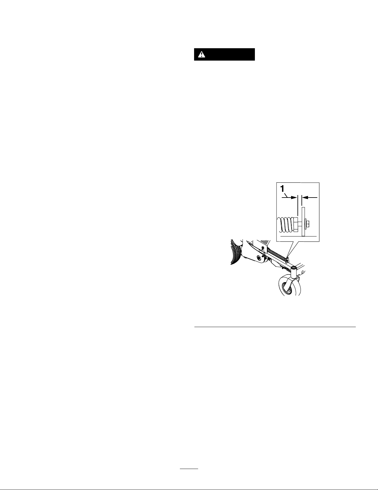
7.Securethecoverpaneltothechassiswiththe
2thumbscrewsand2washers(Figure47)that
youremovedinstep3,andtorquetheboltsto
37to45N∙m(27to33in-lb)
AdjustingtheTineDrive Chain
1.Shutofftheengine,engagetheparkingbrake,
waitforallmovingpartstostop,andremove
thekey.
2.Lifttherearofthemachineandsupportusing
jackstandsorequivalentsupport.
AdjustingtheReturn-to-Up Spring
WARNING
Springshavestoredenergy .Overtightening
thespringsmaycausethespringstofail
whichcancauseseriousinjuryordeathand
damagetothemachineandproperty.
Makesurespringsareproperlyadjusted
and/orreplacedasspeciedintheOperator's
manual.
3.Checkthechainsoneachsideoftheidler
sprocket,onbothsidesofthemachine,for
propertension.Thechainsshouldbeableto
moveupanddown1/4to1/2inch(6to12mm).
4.T oadjustthechaintension,loosentheidlerbolt
andpushdownonthesprockettotightenthe
chain.
Important:Donotovertightenthechain.
Signicantchainwearcanoccurandwill
shortenthelifeofanovertightenedchain.
5.Checkthechaintensionandtightentheidler
bolt.
Checkthegapbetweenthespringbracketandthe
endofthespringasshowninFigure48.Thegap
shouldmeasure1.38inch(35mm).Theadjustment
ismadebyturningtheboltatthefrontofeachspring
(clockwisewillshortenthegap,counter-clockwisewill
lengthenthegap).
g233568
Figure48
1.1.38inch(35mm)
Important:Thespringsmustbereplaceditthe
gapislessthan1.13inches(29mm).
Alwaysreplacebothreturn-to-upsprings.This
preventsunevenloadingandpossibledamageto
themachine.
42
Page 43

Cleaning
CleaningtheDebrisfrom theMachine
CleaningtheEngineand theExhaustSystemArea
ServiceInterval:Beforeeachuseordaily(more
oftenindryordirtyconditions).
CAUTION
Excessivedebrisaroundenginecoolingair
intakeandexhaustsystemareacancause
engine,exhaustarea,andhydraulicsystemto
overheat,whichcancreatearehazard.
Cleanalldebrisfromengineandexhaust
systemarea.
1.Shutofftheengine,engagetheparkingbrake,
removethekey,andwaitforallmovingpartsto
stopbeforeleavingtheoperatingposition.
2.Cleanalldebrisfromscreenatthetopofthe
engine,aroundengineshrouding,andexhaust
systemarea.
3.Wipeupanyexcessivegreaseoroilaroundthe
engineandexhaustsystemarea.
ServiceInterval:Beforeeachuseordaily
1.Shutofftheengine,engagetheparkingbrake,
removethekey,andwaitforallmovingpartsto
stopbeforeleavingtheoperatingposition.
2.Cleanoffanyoil,debris,orgrassbuilduponthe
machineandaeratordeck.
3.Cleanoffanydebrisorgrassunderthechain
guards,aroundthefueltank,andaroundthe
engineandexhaustarea.
DisposingofWaste
DisposingoftheEngineOil
Engineoilandhydraulicuidarebothpollutantsto
theenvironment.Disposeofusedoilatacertied
recyclingcenteroraccordingtoyourstateandlocal
regulations.
DisposingoftheBattery
DANGER
RemovingtheEngine ShroudsandCleaningthe CoolingFins
ServiceInterval:Every80hours
1.Shutofftheengine,engagetheparkingbrake,
removethekey,andwaitforallmovingpartsto
stopbeforeleavingtheoperatingposition.
2.Removecoolingshroudsfromengine.
3.Cleancoolingnsoftheengine.
Note:Alsocleandust,dirt,andoilfromexternal
surfacesofengine,whichcancauseimproper
cooling.
4.Installthecoolingshroudsintotheengine.
Important:Operatingtheenginewithout
coolingshroudscausesenginedamagedue
tooverheating.Donotoperatethemachine
withoutthecoolingshrouds.
Batteryelectrolytecontainssulfuricacid,
whichispoisonousandcancausesevere
burns.Swallowingelectrolytecanbefatalor
ifittouchesskincancausesevereburns.
•Wearsafetyglassestoshieldeyes,and
rubberglovestoprotectskinandclothing
whenhandlingelectrolyte.
•Donotswallowelectrolyte.
•Intheeventofanaccident,ushwithwater
andcalladoctorimmediately.
Federallawstatesthatbatteriesshouldnotbeplaced
inthegarbage.Managementanddisposalpractices
forbatteriesmustfollowrelevantfederal,state,or
locallaws.
Ifabatteryisbeingreplacedorifthemachine
containingthebatteryisnolongeroperatingandis
beingscrapped,removethebatteryandtakeittoa
localcertiedrecyclingcenter.Ifnolocalrecycling
isavailablereturnthebatterytoanycertiedbattery
reseller.
43
Page 44

Storage
1.Raisethetines,stopthemachine,shutoffthe
engine,engagetheparkingbrake,andremove
thekey .Placethekeyoutofreachfromchildren
2.Removedirtandgrimefromtheentiremachine.
Important:Youcanwashthemachine
withmilddetergentandwater.Donot
pressure-washthemachine.Avoid
excessiveuseofwater,especiallynearthe
engineandhydrostaticdrive.
3.Servicetheaircleaner;refertoServicingtheAir
Cleaner(page30).
4.Lubricatethemachine;refertoLubrication
(page29).
5.Changetheengineoil;refertoChangingthe
EngineOil(page31).
6.Checkandtightenallbolts,nuts,andscrews.
Repairorreplaceanypartthatisdamaged.
7.Paintallscratchedorbaremetalsurfaces.Paint
isavailablefromyourauthorizedT orodistributor.
8.Storethemachineinaclean,drygarageor
storagearea.
9.Coverthemachinetoprotectitandkeepitclean.
44
Page 45

Troubleshooting
Problem
Thestarterdoesnotcrank.
Theenginedoesnotstart,startshard,or
failstokeeprunning.
PossibleCauseCorrectiveAction
1.Theparkingbrakeisnotengaged.1.Engagetheparkingbrake.
2.Thebatterydoesnothaveafull
charge.
3.Theelectricalconnectionsare
corroded,looseorfaulty.
4.Afuseisblown.4.Replacetheblownfuse.
5.Arelayorswitchisnotfunctioning
properly.
1.Thefueltankisempty.1.Fillthefueltank.
2.Thefuel-shutoffvalveisclosed.2.Openthefuel-shutoffvalve.
3.Thethrottleandchokearenotinthe
correctposition.
4.Thereisdirt,water,orstalefuelisin
thefuelsystem.
5.Theaircleanerisdirty.
6.Theelectricalconnectionsare
corroded,looseorfaulty.
7.Arelayorswitchisnotfunctioning
properly.
8.Thesparkplugisfaulty.
9.Thespark-plugwireisnotconnected.
10.Theambienttemperatureistoolow.10.Placethemachineintoawarmer
2.Chargethebattery.
3.Checktheelectricalconnectionsfor
goodcontact.Cleantheconnector
terminalsthoroughlywithelectrical
contactcleaner,applydielectric
grease,andreconnect.
5.ContactanAuthorizedServiceDealer.
3.Ensurethatthethrottlelevelismidway
betweentheSLOWandFASTpositions,
andthechokeisintheONpositionfor
acoldengineortheOFFpositionfora
warmengine.
4.ContactanAuthorizedToroservice
dealer.
5.Cleanorreplacetheair-cleaner
element.
6.Checktheelectricalconnections
forgoodcontact.Cleanconnector
terminalsthoroughlywithelectrical
contactcleaner,applydielectric
grease,andconnect.
7.ContactanAuthorizedServiceDealer.
8.Clean,adjust,orreplacethespark
plug.
9.Checkthespark-plugwireconnection.
environmentandallowthehydraulic
uidandengineoiltowarmsufciently.
Theenginelosespower.
Theengineoverheats.
Themachinepullsleftorright(withlevers
fullyforward).
1.Theengineloadisexcessive.1.Reducethegroundspeedoraeration
2.Theaircleanerisdirty.
3.Theoillevelinthecrankcaseislow.3.Addoiltothecrankcase.
4.Thecoolingnsandairpassagesfor
theengineareplugged.
5.Thereisdirt,water,orstalefuelisin
thefuelsystem.
1.Theengineloadisexcessive.1.Reducethegroundspeedoraeration
2.Theoillevelinthecrankcaseislow.2.Addoiltothecrankcase.
3.Thecoolingnsandairpassagesfor
theengineareplugged.
1.Thetirepressureindrivetiresisnot
correct.
2.Thetrackingneedsadjustment.2.Adjustthetraction-controllinkage.
depth.
2.Cleanorreplacetheair-cleaner
element.
4.Removetheobstructionsfromthe
coolingnsandairpassages.
5.ContactanAuthorizedServiceDealer.
depth.
3.Removetheobstructionsfromthe
coolingnsandairpassages.
1.Adjustthetirepressureinthedrive
tires.
45
Page 46

Problem
PossibleCauseCorrectiveAction
Themachinedoesnotdrive.
Thereisabnormalvibration.
Thetinesdonotraise.
Thetinesdonotengagetheground.
1.Thetransmissionbeltworn,loose,or
broken.
2.Thetransmissionbeltisoffapulley.2.Changethebelt.
1.Atineisbent.1.Installanewtine.
2.Thetinemountingboltisloose.2.Tightenthetinemountingbolt.
3.Theenginemountingboltsareloose.3.Tightentheenginemountingbolts.
4.Thereisalooseenginepulleyoridler
pulley.
5.Theenginepulleyisdamaged.
6.Abeltisdamaged.6.Installanewbelt.
7.Thechainsarenotproperlytensioned.
1.Thereisashortinthewireharness.
2.Thereturn-to-upspringsarenot
properlyadjusted.
3.Thereturn-to-upspringsaredamaged.3.Replacethereturn-to-upsprings.
1.Thetinedownpressuresettingistoo
low.
2.Electronicdepthcontrolissettoo
shallow.
3.Theharness/switchisdamaged.3.ContactanAuthorizedServiceDealer.
4.Theauxiliaryreservoirislowonoil.4.Addoiltothereservoir.
1.Changethebelt.
4.Tightentheappropriatepulley.
5.ContactanAuthorizedServiceDealer.
7.Checkthedrivewheelchaintension
andthetinedrive-chaintension.
1.ContactanAuthorizedServiceDealer.
2.Adjustthereturn-to-upsprings.
1.Increasethetinedownpressure.
2.Increasetheelectricaldepthcontrol
setting.
46
Page 47

Notes:
Page 48

 Loading...