

Page 1
FormNo.3367-266RevA
g014653
CommercialWalk-BehindMower
FloatingDeck,SplitLever,HydroDrivewith
36in,40in,48inor52inTURBOFORCE
CuttingUnit
ModelNo.30484—SerialNo.311000001andUp
®
ModelNo.30486—SerialNo.311000001andUp
ModelNo.30488—SerialNo.311000001andUp
ModelNo.30489—SerialNo.311000001andUp
ToregisteryourproductordownloadanOperator'sManualorPartsCatalogatnocharge,gotowww.T oro.com.OriginalInstructions(EN)
Page 2
WARNING
CALIFORNIA
Proposition65Warning
Theengineexhaustfromthisproduct
containschemicalsknowntotheStateof
Californiatocausecancer,birthdefects,
orotherreproductiveharm.
ThissparkignitionsystemcomplieswithCanadian
ICES-002.
Important:Thisengineisnotequippedwitha
sparkarrestermufer.ItisaviolationofCalifornia
PublicResourceCodeSection4442touseoroperate
theengineonanyforest-covered,brush-covered,or
grass-coveredland.Otherstatesorfederalareas
mayhavesimilarlaws.
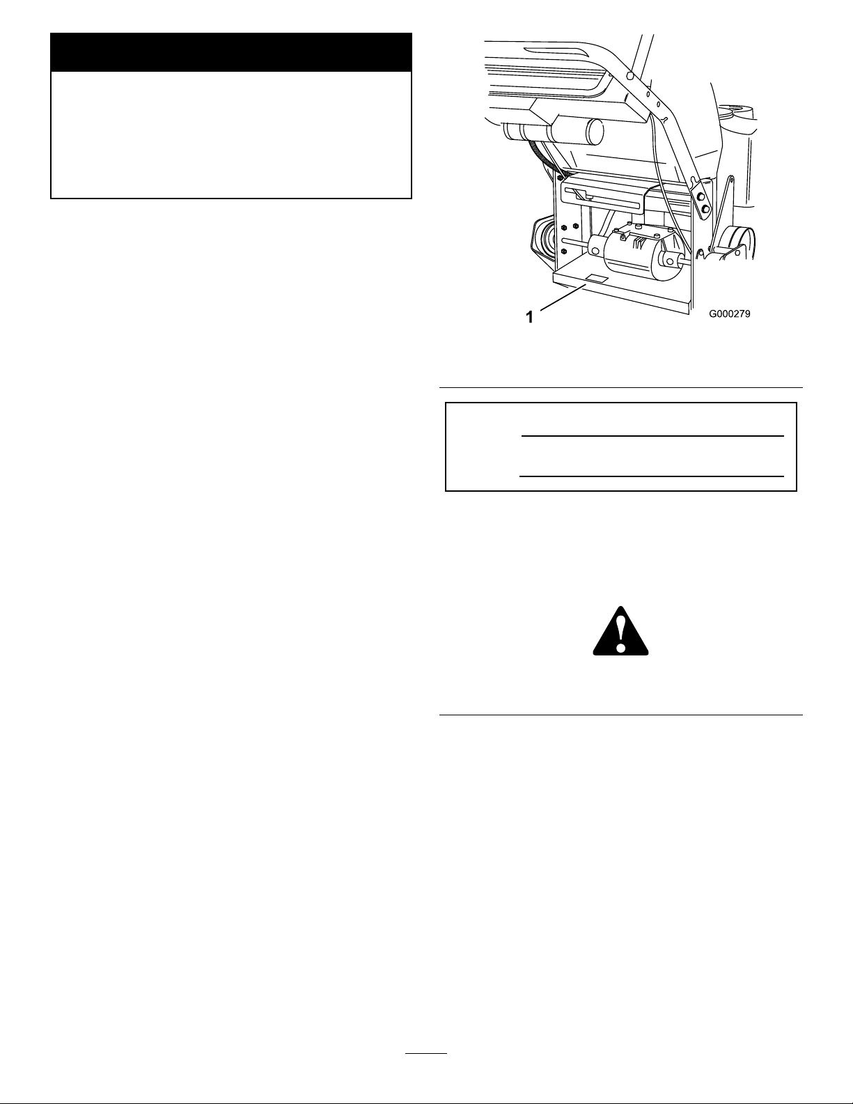
Figure1
1.Modelandserialnumberlocation
Theenclosed
Engine Owner’ s Man ual
issupplied
forinformationregardingtheUSEnvironmental
ProtectionAgency(EPA)andtheCalifornia
EmissionControlRegulationofemissionsystems,
maintenance,andwarranty.Replacementsmaybe
orderedthroughtheenginemanufacturer.
Introduction
Thisrotary-blade,lawnmowerisintendedtobe
usedbyresidentialhomeownersorprofessional,
hiredoperators.Itisdesignedprimarilyforcutting
grassonwell-maintainedlawnsonresidential
orcommercialproperties.Itisnotdesignedfor
cuttingbrushorforagriculturaluses.
Readthisinformationcarefullytolearnhowtooperate
andmaintainyourproductproperlyandtoavoidinjury
andproductdamage.Youareresponsibleforoperating
theproductproperlyandsafely.
YoumaycontactTorodirectlyatwww .Toro.comfor
productandaccessoryinformation,helpndinga
dealer,ortoregisteryourproduct.
ModelNo.
SerialNo.
Thismanualidentiespotentialhazardsandhas
safetymessagesidentiedbythesafetyalertsymbol
(Figure2),whichsignalsahazardthatmaycauseserious
injuryordeathifyoudonotfollowtherecommended
precautions.
Figure2
1.Safetyalertsymbol
Thismanualuses2otherwordstohighlightinformation.
Importantcallsattentiontospecialmechanical
informationandNoteemphasizesgeneralinformation
worthyofspecialattention.
Wheneveryouneedservice,genuineToroparts,or
additionalinformation,contactanAuthorizedService
DealerorToroCustomerServiceandhavethemodel
andserialnumbersofyourproductready .
Figure1
identiesthelocationofthemodelandserialnumbers
ontheproduct.Writethenumbersinthespace
provided.
©2010—TheT oro®Company
8111LyndaleAvenueSouth
Bloomington,MN55420
Contents
Introduction.................................................................2
Safety...........................................................................4
SafeOperatingPractices.......................................4
ToroMowerSafety...............................................5
SlopeIndicator.....................................................7
SafetyandInstructionalDecals.............................8
ProductOverview......................................................11
Controls.............................................................11
Contactusatwww.Toro.com.
2
PrintedintheUSA.
AllRightsReserved
Page 3

Specications.....................................................12
Operation...................................................................13
AddingFuel.......................................................13
CheckingtheEngineOilLevel............................14
ThinkSafetyFirst...............................................14
OperatingtheParkingBrake...............................14
StartingandStoppingtheEngine........................14
OperatingtheMowerBladeControl
(PTO)............................................................15
TheSafetyInterlockSystem................................16
DrivingForwardorBackward.............................16
StoppingtheMachine.........................................17
PushingtheMachinebyHand.............................17
TransportingMachines.......................................18
SideDischargingorMulchingtheGrass..............18
AdjustingtheHeight-of-Cut...............................18
AdjustingtheAnti-ScalpRollers.........................19
AdjustingtheFlowBafe...................................20
PositioningtheFlowBafe.................................20
UsingtheMid-SizeWeight..................................22
Maintenance...............................................................23
RecommendedMaintenanceSchedule(s)................23
Lubrication.............................................................24
HowtoGrease...................................................24
LubricatingtheBearings.....................................24
GreasingthePTODriveBeltIdlerandMower
DeckBeltIdler...............................................24
EngineMaintenance...............................................25
ServicingtheAirCleaner....................................25
ServicingtheEngineOil.....................................26
ServicingtheSparkPlugs....................................27
FuelSystemMaintenance.......................................28
DrainingtheFuelTank.......................................28
ServicingtheFuelFilter......................................29
ServicingtheFuelV entSystem...........................29
ElectricalSystemMaintenance................................30
ServicingtheBattery...........................................30
ServicingtheFuses.............................................32
DriveSystemMaintenance.....................................33
AdjustingtheTracking.......................................33
CheckingtheTirePressure.................................33
ReplacingtheCasterWheelFork
Bushings........................................................34
ServicingtheCasterWheelandBearings.............35
AdjustingtheElectricClutch..............................35
CoolingSystemMaintenance..................................36
CleaningtheAirIntakeScreen............................36
BrakeMaintenance.................................................36
ServicingtheBrake.............................................36
BeltMaintenance....................................................37
ReplacingtheMowerBelt...................................37
ReplacingthePTODriveBelt.............................38
AdjustingthePTODriveBeltIdlerSpring
Anchor...........................................................39
ReplacingthePumpDriveBelt...........................39
ControlsSystemMaintenance.................................40
AdjustingtheMotionControlHandle
Positions........................................................40
HydraulicSystemMaintenance...............................42
ServicingtheHydraulicSystem...........................42
MowerDeckMaintenance......................................45
ServicingtheCuttingBlades...............................45
CorrectingtheMowerQualityofCut..................47
FrameSetUp.....................................................48
CheckingtheMowerDeckFront-to-Rear
Pitch...............................................................49
ChangingtheMowerDeckFront-to-Rear
Pitch...............................................................50
CheckingtheMowerDeckSide-to-Side
Height............................................................50
ChangingtheMowerDeckSide-to-Side
Height............................................................51
MatchingHeightofCut......................................51
ReplacingtheGrassDeector.............................52
Cleaning.................................................................52
CleaningUndertheMower.................................52
WasteDisposal...................................................52
Storage.......................................................................53
CleaningandStorage..........................................53
Troubleshooting.........................................................54
Schematics.................................................................56
3
Page 4

Safety
Note:Theadditionofattachmentsmadeby
othermanufacturersthatdonotmeetAmerican
NationalStandardsInstitutecerticationwillcause
noncomplianceofthismachine.
Improperuseormaintenancebytheoperatororowner
canresultininjury.Toreducethepotentialforinjury,
complywiththesesafetyinstructionsandalwayspay
attentiontothesafetyalertsymbol,whichmeans
CAUTION,WARNING,orDANGER-“personalsafety
instruction."Failuretocomplywiththeinstructionmay
resultinpersonalinjuryordeath.
–Neverremovegascaporaddfuelwithengine
running.Allowenginetocoolbeforerefueling.
Donotsmoke.
–Neverrefuelordrainthemachineindoors.
•Checkthatoperator’spresencecontrols,safety
switchesandshieldsareattachedandfunctioning
properly.Donotoperateunlesstheyarefunctioning
properly.
Operation
•Lightningcancausesevereinjuryordeath.If
lightningisseenorthunderisheardinthearea,do
notoperatethemachine;seekshelter.
SafeOperatingPractices
ThefollowinginstructionsarefromANSIstandard
B71.4-2004.
Training
•ReadtheOperator’sManualandothertraining
material.Iftheoperator(s)ormechanic(s)cannot
readEnglishitistheowner’sresponsibilitytoexplain
thismaterialtothem.
•Becomefamiliarwiththesafeoperationofthe
equipment,operatorcontrols,andsafetysigns.
•Alloperatorsandmechanicsshouldbetrained.The
ownerisresponsiblefortrainingtheusers.
•Neverletchildrenoruntrainedpeopleoperateor
servicetheequipment.Localregulationsmayrestrict
theageoftheoperator.
•Theowner/usercanpreventandisresponsiblefor
accidentsorinjuriesoccurringtohimselforherself,
otherpeopleorproperty.
•Neverrunanengineinanenclosedarea.
•Onlyoperateingoodlight,keepingawayfromholes
andhiddenhazards.
•Besurealldrivesareinneutralandparkingbrakeis
engagedbeforestartingengine.Onlystartengine
fromtheoperator’sposition.
•Besureofyourfootingwhileusingthismachine,
especiallywhenbackingup.Walk,don’trun.Never
operateonwetgrass.Reducedfootingcouldcause
slipping.
•Slowdownanduseextracareonhillsides.Besure
totravelsidetosideonhillsides.Turfconditions
canaffectthemachine’ sstability.Usecautionwhile
operatingneardrop-offs.
•Slowdownandusecautionwhenmakingturnsand
whenchangingdirectionsonslopes.
•Neverraisedeckwiththebladesrunning.
•NeveroperatewiththePTOshield,orotherguards
notsecurelyinplace.Besureallinterlocksare
attached,adjustedproperly,andfunctioningproperly .
Preparation
•Evaluatetheterraintodeterminewhataccessories
andattachmentsareneededtoproperlyand
safelyperformthejob.Onlyuseaccessoriesand
attachmentsapprovedbythemanufacturer.
•Wearappropriateclothingincludinghardhat,safety
glassesandhearingprotection.Longhair,loose
clothingorjewelrymaygettangledinmovingparts.
•Inspecttheareawheretheequipmentistobeused
andremoveallobjectssuchasrocks,toysandwire
whichcanbethrownbythemachine.
•Useextracarewhenhandlinggasolineandother
fuels.Theyareammableandvaporsareexplosive.
–Useonlyanapprovedcontainer
•Neveroperatewiththedischargedeectorraised,
removedoraltered,unlessusingagrasscatcher.
•Donotchangetheenginegovernorsettingor
overspeedtheengine.
•Stoponlevelground,disengagedrives,engage
parkingbrake,shutoffenginebeforeleavingthe
operator’spositionforanyreasonincludingemptying
thecatchersoruncloggingthechute.
•Stopequipmentandinspectbladesafterstriking
objectsorifanabnormalvibrationoccurs.Make
necessaryrepairsbeforeresumingoperations.
•Keephandsandfeetawayfromthecuttingunit.
•Lookbehindanddownbeforebackinguptobesure
ofaclearpath.
4
Page 5

•Keeppetsandbystandersaway.
•Slowdownandusecautionwhenmakingturnsand
crossingroadsandsidewalks.Stopbladesifnot
mowing.
•Beawareofthemowerdischargedirectionanddo
notpointitatanyone.
•Donotoperatethemowerundertheinuenceof
alcoholordrugs.
•Usecarewhenloadingorunloadingthemachine
intoorfromatrailerortruck.
•Usecarewhenapproachingblindcorners,shrubs,
trees,orotherobjectsthatmayobscurevision.
Maintenanceandstorage
•Disengagedrives,setparkingbrake,stopengineand
removekeyordisconnectsparkplugwire.Waitfor
allmovementtostopbeforeadjusting,cleaningor
repairing.
•Cleangrassanddebrisfromcuttingunit,drives,
mufers,andenginetohelppreventres.Cleanup
oilorfuelspillage.
•Letenginecoolbeforestoringanddonotstorenear
ame.
•Shutofffuelwhilestoringortransporting.Donot
storefuelnearamesordrainindoors.
•Parkmachineonlevelground.Setparkingbrake.
Neverallowuntrainedpersonneltoservicemachine.
•Usejackstandstosupportcomponentswhen
required.
•Carefullyreleasepressurefromcomponentswith
storedenergy.
•Disconnectthebatteryorremovesparkplugwire
beforemakinganyrepairs.Disconnectthenegative
terminalrstandthepositivelast.Reconnectthe
positiverstandnegativelast.
•Usecarewhencheckingblades.Wraptheblade(s)or
weargloves,andusecautionwhenservicingthem.
Onlyreplaceblades.Neverstraightenorweldthem.
•Keephandsandfeetawayfrommovingparts.If
possible,donotmakeadjustmentswiththeengine
running.
•Keepallpartsingoodworkingconditionandall
hardwaretightened.Replaceallwornordamaged
decals.
ToroMowerSafety
Thefollowinglistcontainssafetyinformationspecic
toToroproductsandothersafetyinformationyoumust
know .
Thisproductiscapableofamputatinghandsand
feetandthrowingobjects.Alwaysfollowallsafety
instructionstoavoidseriousinjuryordeath.
Thisproductisdesignedforcuttingandrecyclinggrass
or,whenequippedwithagrassbagger,forcatching
cutgrass.Anyuseforpurposesotherthanthesecould
provedangeroustouserandbystanders.
GeneralOperation
•Besuretheareaisclearofotherpeoplebefore
mowing.Stopthemachineifanyoneentersthearea.
•Donottouchequipmentorattachmentpartswhich
maybehotfromoperation.Allowtocoolbefore
attemptingtomaintain,adjustorservice.
•UseonlyToroapprovedattachments.W arrantymay
bevoidedifusedwithunapprovedattachments.
•Checkcarefullyforoverheadclearances(i.e.
branches,doorways,electricalwires)before
operatingunderanyobjectsanddonotcontact
them.
SlopeOperation
Allslopesandrampsrequireextracaution.Ifyoufeel
uneasyonaslope,donotmowit.
•Removeobstaclessuchasrocks,treelimbs,etc.from
themowingarea.
•Watchforholes,rutsorbumps.Tallgrasscanhide
obstacles.
•Usecautionneardrop-offs,ditches,orembankments.
Themachinecouldsuddenlyturnoverifawheel
goesovertheedgeofaclifforditch,orifanedge
cavesin.
•Useextracarewithgrasscatchersorother
attachments.Thesecanchangethestabilityofthe
machine.
•Keepallmovementonslopesslowandgradual.Do
notmakesuddenchangesinspeedordirection.
•Mowslopessidetoside.
•Donotmowslopesgreaterthan20degrees.
Service
•Neverstorethemachineorfuelcontainerinside
wherethereisanopename,suchasnearawater
heaterorfurnace.
•Keepnutsandboltstight,especiallytheblade
attachmentbolts.Keepequipmentingood
condition.
•Nevertamperwithsafetydevices.Checksafety
systemsforproperoperationbeforeeachuse.
5
Page 6

•Useonlygenuinereplacementpartstoensurethat
originalstandardsaremaintained.
•Checkbrakeoperationfrequently.Adjustandservice
asrequired.
6
Page 7
SlopeIndicator
G011841
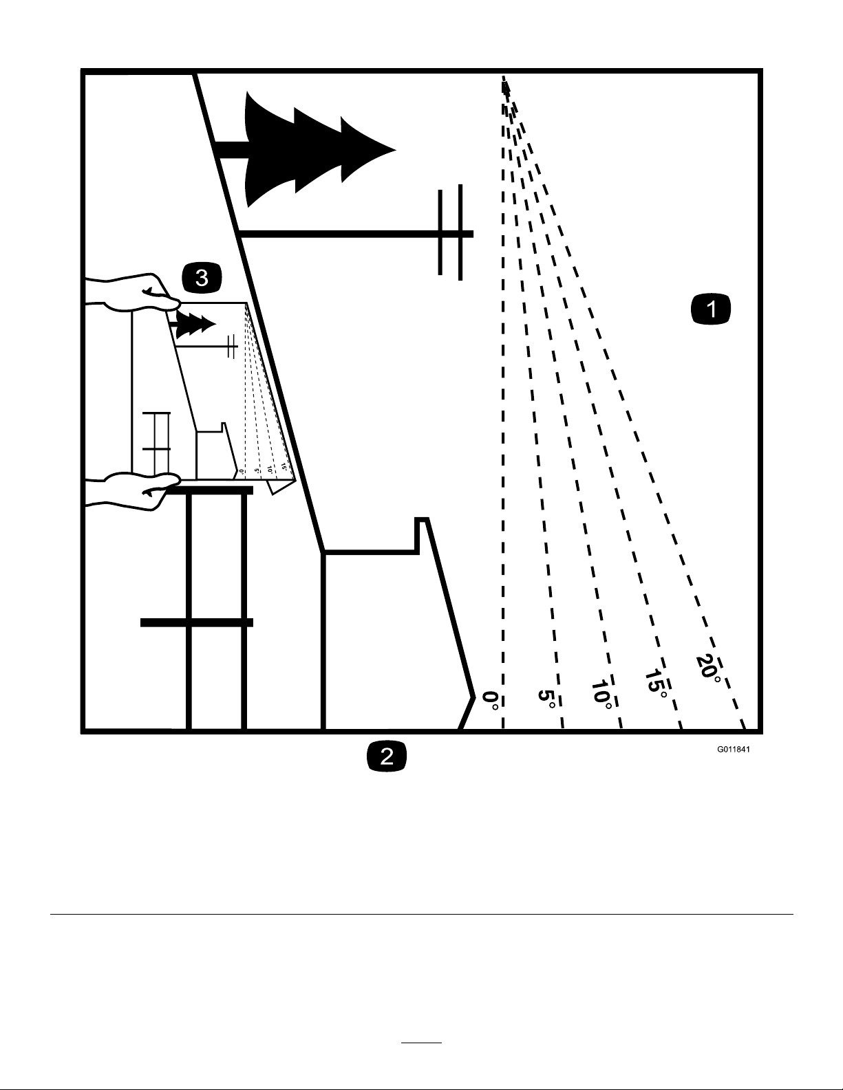
Figure3
Thispagemaybecopiedforpersonaluse.
1.Themaximumslopeyoucansafelyoperatethemachineonis20degrees.Usetheslopecharttodeterminethedegreeofslope
ofhillsbeforeoperating.Donotoperatethismachineonaslopegreaterthan20degrees.Foldalongtheappropriateline
tomatchtherecommendedslope.
2.Alignthisedgewithaverticalsurface,atree,building,fencepole,etc.
3.Exampleofhowtocompareslopewithfoldededge.
7
Page 8
SafetyandInstructional
Decals
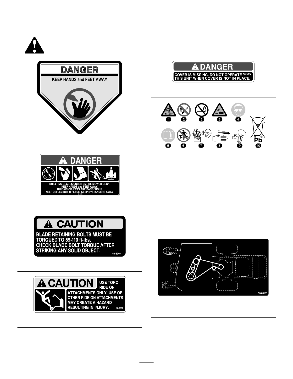
Safetydecalsandinstructionsareeasilyvisibletotheoperatorandarelocatednearanyareaof
potentialdanger.Replaceanydecalthatisdamagedorlost.
98-5954
43-8480
BatterySymbols
Someorallofthesesymbolsareonyourbattery
1.Explosionhazard
2.Nore,opename,or
smoking.
66-1340
3.Causticliquid/chemical
burnhazard
4.Weareyeprotection9.Flusheyesimmediately
5.ReadtheOperator’s
Manual.
6.Keepbystandersasafe
distancefromthebattery.
7.Weareyeprotection;
explosivegasescan
causeblindnessandother
injuries
8.Batteryacidcancause
blindnessorsevereburns.
withwaterandgetmedical
helpfast.
10.Containslead;donot
discard.
68-8340
104-8185
36inmowerdecks
98-0776
8
Page 9

104-8186
40inandlargermowerdecks
104-8569
Manufacturer’sMark
1.Indicatesthebladeisidentiedasapartfromtheoriginal
machinemanufacturer.
110-2067
110-2068
105-7798
1.ReadtheOperator’sManual.
106-0635
112-8720
106-0699
9
Page 10
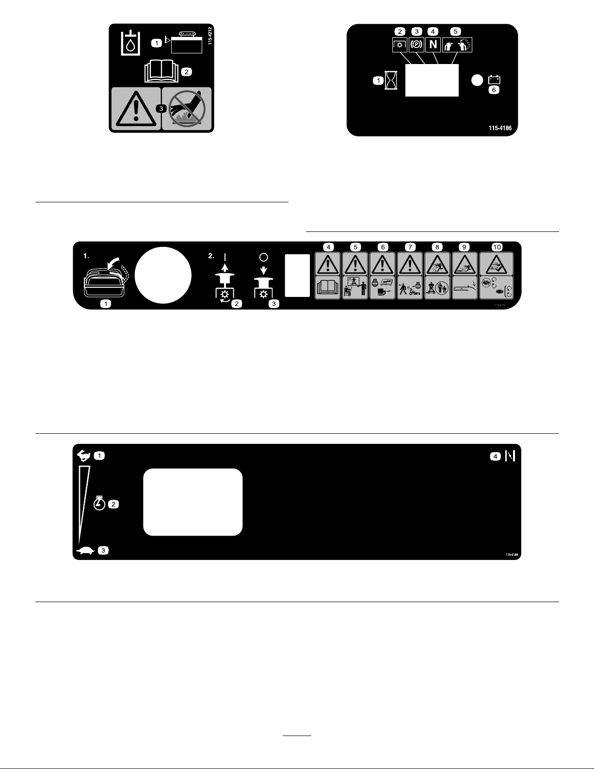
115-4212
1.Hydraulicoillevel3.Warning—donottouch
thehotsurface.
2.ReadtheOperator’s
Manual.
1.Interval
2.PowerT ake-off(PTO)
3.Parkingbrake
4.Neutral
5.Operatorpresenceswitch
6.Battery
115-4186
115–4179
1.Movethemotioncontrollevertotheneutralposition,thenpull
outonPTO(PowerTakeOff)switchtoengagetheblades.
2.PushinonthePTO(PowerT akeOff)todisengagetheblades.7.Thrownobjecthazard—keepbystandersasafedistancefrom
3.Warning—readtheOperator’sManual.8.Thrownobjecthazard—keepdeectorinplace.
4.Warning—donotoperatethismachineunlessyouaretrained.
5.Warning—stoptheengineandremovethesparkplugwire
beforeperforminganymaintenanceonthemachine.
6.Warning—stoptheenginebeforeleavingthemachine.
themachine.
9.Cutting,dismembermenthazardofhandorfoot—stayaway
frommovingparts;keepallguardsandshieldsinplace.
1.Fast2.Enginespeed
115–4189
3.Slow4.Choke
10
Page 11
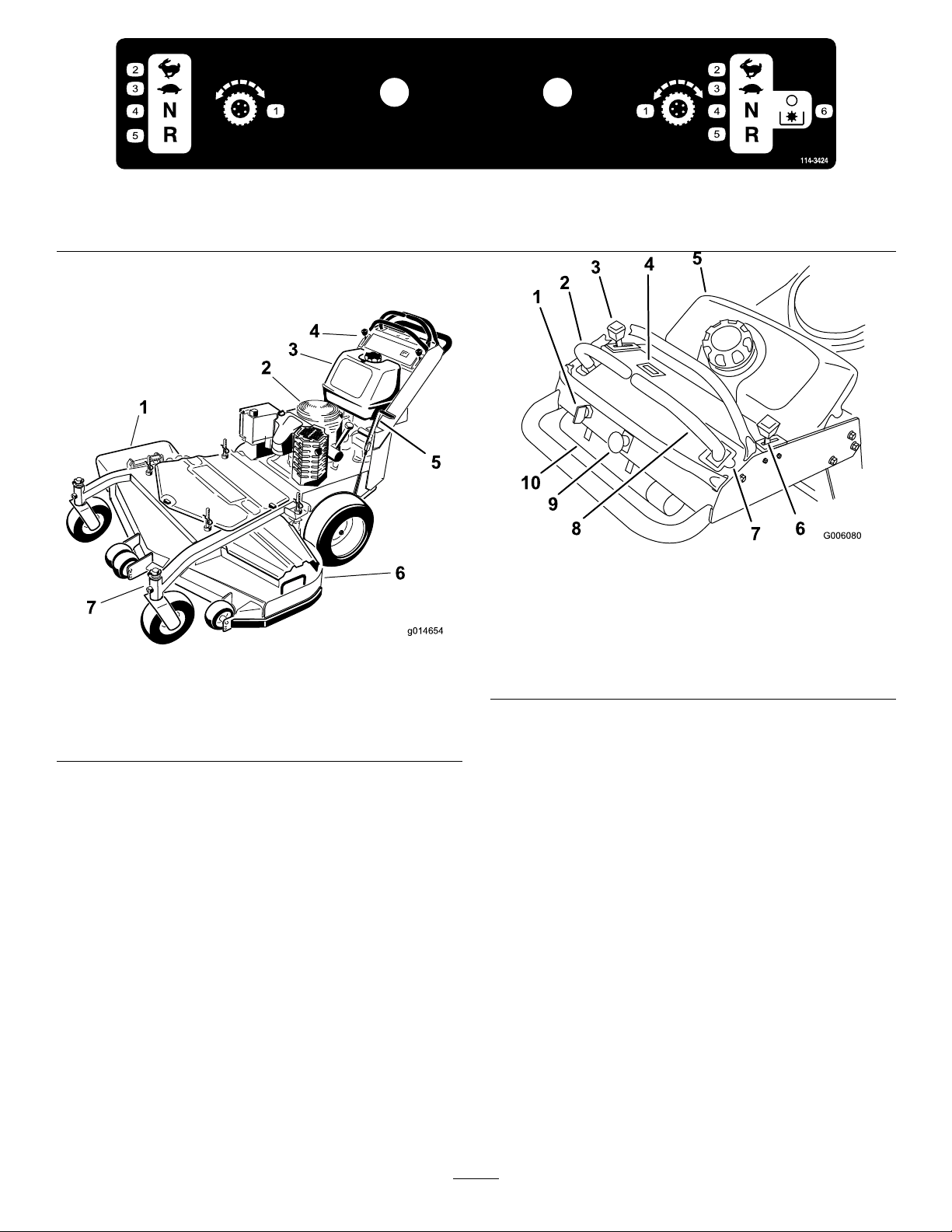
1.Tractioncontrol
g014654
1
2
3
4
5
6
7
2.Fast4.Neutral
ProductOverview
Figure4
1.Sidedischargechute
2.Engine6.Mowerdeck
3.Gastank
4.Controls
5.Parkingbrake
7.Frontcasterwheel
114-3424
3.Slow
1.Ignitionswitch
2.Leftmotioncontrollever7.Neutrallockpositionfor
3.Throttlecontrol8.Rightmotioncontrollever
4.Hourmeter
5.Fueltank
5.Reverse
6.DisengagethePTO(PowerTakeOff)
Figure5
6.Choke
rightmotioncontrollever
9.bladecontrolswitch(PTO)
10.Operatormanualtube
HourMeter
Controls
Becomefamiliarwithallthecontrols(Figure5)before
youstarttheengineandoperatethemachine.
Thehourmeterrecordsthenumberofhourstheengine
hasoperated.Itoperateswhentheengineisrunning.
Usethesetimesforschedulingregularmaintenance
Figure6).
(
SafetyInterlockIndicators
Therearesymbolsonthehourmeterandindicatewith
ablacktrianglethattheinterlockcomponentisinthe
correctposition(Figure6).
BatteryIndicatorLight
WhentheignitionkeyisinitiallyturnedtotheOn
position,thebatteryvoltagewillbedisplayedinthearea
wherethehoursarenormallydisplayed.
Thebatterylightturnsonwhentheignitionisturned
onandwhenthechargeisbelowthecorrectoperating
level(
Figure6).
11
Page 12

Figure6
1.Safetyinterlocksymbols
2.Batterylight
3.Hourmeter
ThrottleControl
Thethrottlecontrolhastwopositions:FastandSlow.
enhanceandexpanditscapabilities.Contactyour
AuthorizedServiceDealerorDistributororgoto
www.Toro.comforalistofallapprovedattachments
andaccessories.
Specications
Note:Specicationsanddesignaresubjecttochange
withoutnotice.
36inchmowers:
Widthwithdeectordown51–1/8inches(130cm)
Length
Height
Weight
78–1/2inches(199cm)
46inches(117cm)
667lb(303kg)
Choke
Usethechoketostartacoldengine.
BladeControlSwitch(PTO)
Thebladecontrolswitch(PTO)isusedtoengage
theelectricclutchtodrivethemowerbladeswiththe
rightsidemotioncontrolleverinthecenter,un-locked
position.Pulltheswitchuptoengagethebladesand
release.Todisengagetheblades,pushthebladecontrol
switch(PTO)downormoveorreleasetherightside
motioncontrolleverintotheneutrallockposition.
IgnitionSwitch
Thisswitchisusedtostartthemowerengineandhas
threepositions:Start,RunandOff.
MotionControlLevers
Themotioncontrolleversareusedtodrivethemachine
forward,reverse,andturneitherdirection.
40inchmowers:
Widthwithdeectordown55–1/2inches(141cm)
Length
Height
Weight
75–3/8inches(192cm)
46inches(117cm)
667lb(303kg)
48inchmowers:
Widthwithdeectordown63–1/2inches(161cm)
Length
Height
Weight
77–3/4inches(198cm)
46inches(117cm)
682lb(309kg)
52inchmowers:
Widthwithdeectordown67–5/8inches(171.7cm)
Length
Height
Weight
77–3/4inches(198cm)
46inches(117cm)
721lb(327kg)
NeutralLockPosition
Theneutrallockpositionisusedwiththesafetyinterlock
systemtoengageanddisengagethemowerbladesand
todetermineneutralposition.
FuelShut-offValve
Closethefuelshut-offvalve(underthefueltank)when
transportingorstoringthemower.
Attachments/Accessories
AselectionofToroapprovedattachmentsand
accessoriesareavailableforusewiththemachineto
12
Page 13

Operation
AddingFuel
UseUnleadedRegularGasolinesuitablefor
automotiveuse(85pumpoctaneminimum).Leaded
regulargasolinemaybeusedifunleadedregularisnot
available.
Important:Neverusemethanol,gasoline
containingmethanol,orgasoholcontainingmore
than10%ethanolbecausethefuelsystemcouldbe
damaged.Donotmixoilwithgasoline.
DANGER
Incertainconditions,gasolineisextremely
ammableandhighlyexplosive.Areorexplosion
fromgasolinecanburnyouandothersandcan
damageproperty.
•Fillthefueltankoutdoors,inanopenarea,
whentheengineiscold.Wipeupanygasoline
thatspills.
•Neverllthefueltankinsideanenclosedtrailer.
•Donotllthefueltankcompletelyfull.Add
gasolinetothefueltankuntilthelevelis1/4to
1/2inch(6to13mm)belowthebottomofthe
llerneck.Thisemptyspaceinthetankallows
gasolinetoexpand.
•Neversmokewhenhandlinggasoline,andstay
awayfromanopenameorwheregasoline
fumesmaybeignitedbyaspark.
•Storegasolineinanapprovedcontainerand
keepitoutofthereachofchildren.Neverbuy
morethana30-daysupplyofgasoline.
•Donotoperatewithoutentireexhaustsystem
inplaceandinproperworkingcondition.
DANGER
Incertainconditionsduringfueling,static
electricitycanbereleasedcausingasparkwhich
canignitethegasolinevapors.Areorexplosion
fromgasolinecanburnyouandothersandcan
damageproperty.
•Alwaysplacegasolinecontainersontheground
awayfromyourvehiclebeforelling.
•Donotllgasolinecontainersinsideavehicle
oronatruckortrailerbedbecauseinterior
carpetsorplastictruckbedlinersmayinsulate
thecontainerandslowthelossofanystatic
charge.
•Whenpractical,removegas-powered
equipmentfromthetruckortrailerandrefuel
theequipmentwithitswheelsontheground.
•Ifthisisnotpossible,thenrefuelsuch
equipmentonatruckortrailerfromaportable
container,ratherthanfromagasolinedispenser
nozzle.
•Ifagasolinedispensernozzlemustbeused,
keepthenozzleincontactwiththerimofthe
fueltankorcontaineropeningatalltimesuntil
fuelingiscomplete.
WARNING
Gasolineisharmfulorfatalifswallowed.
Long-termexposuretovaporscancauseserious
injuryandillness.
•Avoidprolongedbreathingofvapors.
•Keepfaceawayfromnozzleandgastankor
conditioneropening .
•Keepgasawayfromeyesandskin.
UsingStabilizer/Conditioner
Useafuelstabilizer/conditionerinthemachineto
providethefollowingbenets:
•Keepsgasolinefreshduringstorageof90daysor
less.Forlongerstorageitisrecommendedthatthe
fueltankbedrained.
•Cleanstheenginewhileitruns
•Eliminatesgum-likevarnishbuildupinthefuel
system,whichcauseshardstarting
Important:Donotusefueladditives
containingmethanolorethanol.
Addthecorrectamountofgas
stabilizer/conditionertothegas.
13
Page 14
Note:Afuelstabilizer/conditionerismost
effectivewhenmixedwithfreshgasoline.To
minimizethechanceofvarnishdepositsinthefuel
system,usefuelstabilizeratalltimes.
CAUTION
Childrenorbystandersmaybeinjuredifthey
moveorattempttooperatethemachinewhileit
isunattended.
FillingtheFuelT ank
1.Shuttheengineoffandsettheparkingbrake.
2.Cleanaroundfueltankcapandremovethecap.
Addunleadedregulargasolinetofueltank,untilthe
levelis1/4to1/2inch(6to13mm)belowthe
bottomofthellerneck.Thisspaceinthetank
allowsgasolinetoexpand.Donotllthefueltank
completelyfull.
3.Installfueltankcapsecurely.Wipeupanygasoline
thatmayhavespilled.
CheckingtheEngineOilLevel
Beforeyoustarttheengineandusethemachine,check
theoillevelintheenginecrankcase;refertoChecking
OilLevelinEngineMaintenance.
Note:Determinetheleftandrightsidesofthe
machinefromthenormaloperatingposition.
Alwaysremovetheignitionkeyandsettheparking
brakewhenleavingthemachineunattended,even
ifjustforafewminutes.
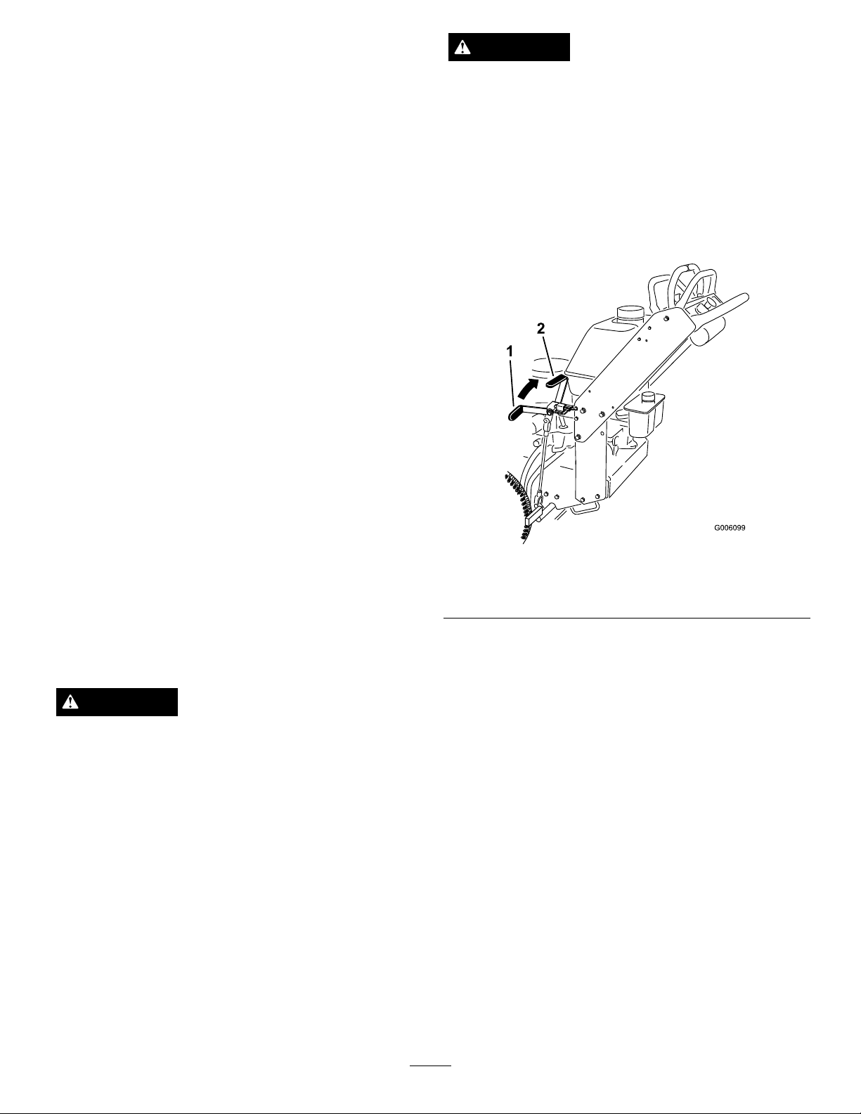
SettingtheParkingBrake
Pulltheparkingbrakeleverrearward(Figure7).
ThinkSafetyFirst
Carefullyreadallthesafetyinstructionsanddecalsin
thesafetysection.Knowingthisinformationcould
helpyouoranybystandersavoidinjury.
Theuseofprotectiveequipmentforeyes,hearing,feet
andheadisrecommended.
CAUTION
Thismachineproducessoundlevelsinexcessof
85dBAattheoperator’searandcancausehearing
lossthroughextendedperiodsofexposure.
Wearhearingprotectionwhenoperatingthis
machine.
OperatingtheParkingBrake
Alwayssettheparkingbrakewhenyoustopthe
machineorleaveitunattended.Beforeeachuse,check
theparkingbrakeforproperoperation.
Iftheparkingbrakedoesnotholdsecurely,adjustit.
RefertoServicingtheParkingBrake.
Figure7
1.Parkingbrakelever(inthe
releasedposition)
2.Parkingbrakelever(inthe
engagedposition)
ReleasingtheParkingBrake
Pushtheparkingbrakeleverforward.
StartingandStoppingthe
Engine
StartingtheEngine
1.Connectthewirestothesparkplugs.
2.Openthefuelvalve.
3.Settheparkingbrake.
4.Movethethrottlecontroltofastandmovethe
chokelevertotheonpositionbeforestartingacold
engine(Figure8).
Note:Awarmorhotenginemaynotrequire
choking.Tostartawarmengine,movethrottle
controlmidwaybetweenthefastandslow
positions.
14
Page 15
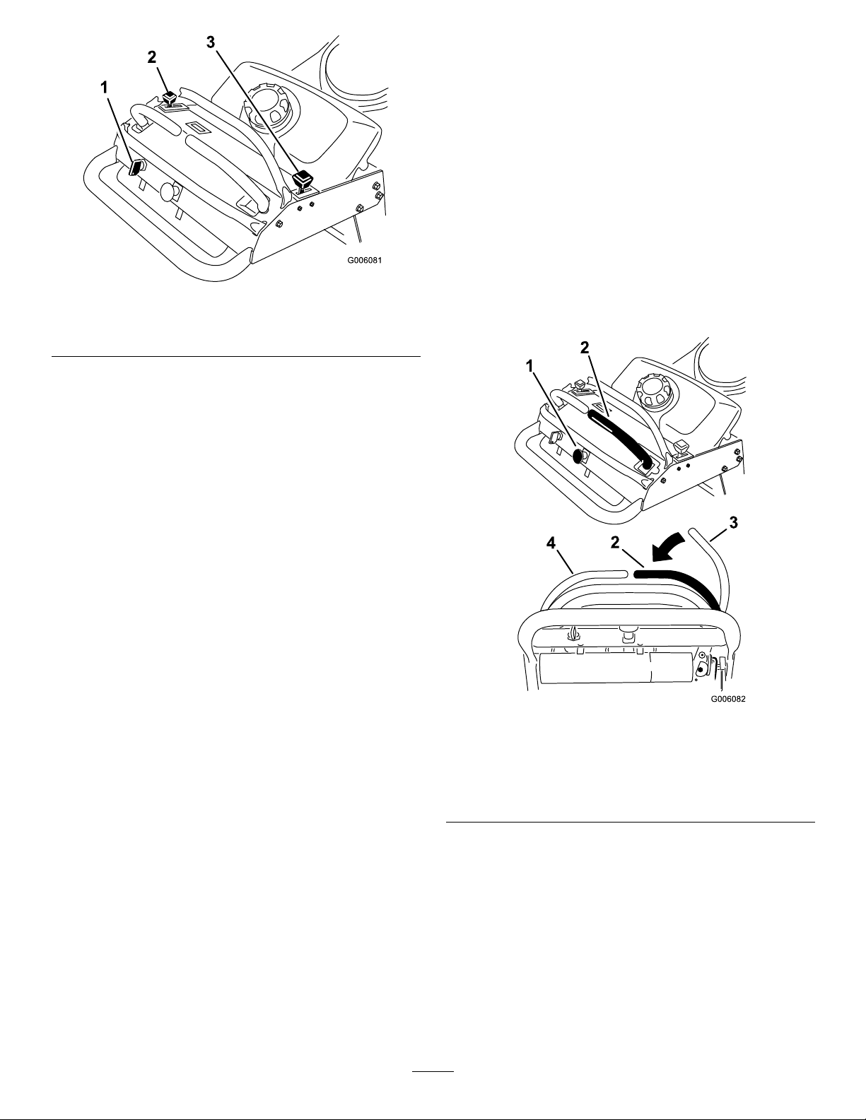
Figure8
1.Ignitionswitch
2.Throttlelever
3.Choke
5.Turntheignitionkeytothestartpositionto
energizethestarter.Whentheenginestarts,release
thekey .
Note:Donotengagethestarterformorethan
5secondsatatime.Iftheenginefailstostart,
allowfora15secondcool-downperiodbetween
attempts.Failuretofollowtheseinstructionscan
burnoutthestartermotor.
OperatingtheMowerBlade
Control(PTO)
Thebladecontrolswitch(PTO)isusedinconjunction
withtherightsidemotioncontrollevertoengageand
disengagethemowerblades.
EngagingtheMowerBlades(PTO)
1.Toengagethemowerblades,movetherightside
motioncontrollevertothecenter,un-locked
position(Figure9).
2.Pullthebladecontrolswitch(PTO)upandrelease
itwhileholdingdowntherightsidemotioncontrol
leverinthecenter,un-lockedposition.
6.Whenenginestarts,movethethrottlecontrol
betweenthefastandslowpositionandmovethe
chokelevertotheoffposition.Allowtheengine
towarmupandthenmovethethrottlecontrolto
thefastposition.
StoppingtheEngine
1.Movethemotioncontrolleverstoneutralandmove
therightsidemotioncontrolleverintotheneutral
lockposition.
2.Movethethrottlelevertoslow(Figure8).
3.Iftheenginehasbeenworkinghardorishot,let
theengineidlefor30to60secondsbeforeturning
theengineoff.
4.Tostoptheengine,turntheignitionkeytooff.
Important:Makesurefuelshutoffvalve
isclosedbeforetransportingorstoringthe
machine,asfuelleakagemayoccur.Before
storingthemachine,pullwireoffsparkplug(s)
topreventpossibilityofaccidentalstarting.
Figure9
1.Bladecontrolswitch(PTO)
2.Rightsidemotioncontrol
leverpusheddownintothe
center,un-lockedposition
3.Rightmotioncontrollever
inneutrallockposition
4.Leftmotioncontrollever
DisengagingtheMowerBlades(PTO)
Thefollowingaretwooptionsfordisengagingthe
mowerblades.
•Pushthebladecontrolswitch(PTO)downtothe
offposition.
•Movethemotioncontrolleverstoneutralandmove
therightsidemotioncontrolleverintotheneutral
lockposition.
15
Page 16
TheSafetyInterlockSystem
CAUTION
Ifsafetyinterlockswitchesaredisconnectedor
damagedthemachinecouldoperateunexpectedly
causingpersonalinjury.
•Donottamperwiththeinterlockswitches.
•Checktheoperationoftheinterlockswitches
dailyandreplaceanydamagedswitchesbefore
operatingthemachine.
UnderstandingtheSafetyInterlock
System
Thesafetyinterlocksystemisdesignedtopreventthe
mowerbladesfromrotatingunless:
•Therightsidemotioncontrolleverismovedtothe
center,un-lockedposition.
•Thebladecontrolswitch(PTO)ispulledon.
Thesafetyinterlocksystemisdesignedtostopthe
mowerbladesifyoumoveorreleasetherightside
motioncontrolleverintotheneutrallockposition.
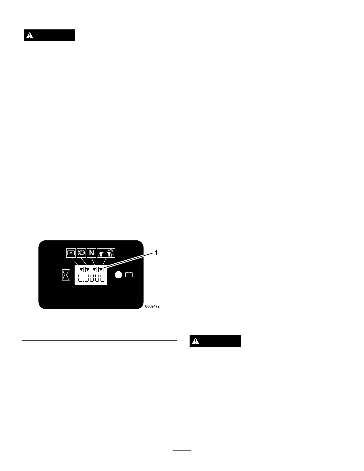
Thehourmeterhassymbolstonotifytheuserwhen
theinterlockcomponentisinthecorrectposition.
Whenthecomponentisinthecorrectposition,a
trianglewilllightupinthecorrespondingsquare.
2.Settheparkingbrake.
3.Movetherightsidemotioncontrollevertothe
center,un-lockedposition.Thebladesshould
notrotate.
4.Movethemotioncontrolleversforward.The
engineshouldkill.
5.Starttheengineandreleasetheparkingbrake.
6.Movetherightsidemotioncontrollevertothe
center,un-lockedposition.
7.Continueholdingtherightsidemotioncontrollever
inthecenter,un-lockedpositionandpulluponthe
bladecontrolswitch(PTO)andrelease.Theclutch
shouldengageandthemowerbladesbeginrotating.
8.Moveorreleasetherightsidemotioncontrollever
intotheneutrallockposition.Thebladesshould
stoprotating.
9.Movetherightsidemotioncontrollevertothe
center,un-lockedposition.
10.Continueholdingtherightsidemotioncontrollever
inthecenter,un-lockedpositionandpulluponthe
bladecontrolswitch(PTO)andrelease.Theclutch
shouldengageandthemowerbladesbeginrotating.
11.Pushthebladecontrolswitch(PTO)downtothe
offposition.Thebladesshouldstoprotating.
12.Withtheenginerunning,pullupthebladecontrol
switch(PTO)andreleasewithoutholdingright
sidemotioncontrollevertothecenter,un-locked
position.Thebladesshouldnotrotate.
Figure10
1.Triangleslightupwhentheinterlockcomponentsareinthe
correctposition
TestingtheSafetyInterlockSystem
ServiceInterval:Beforeeachuseordaily
Testthesafetyinterlocksystembeforeyouusethe
machineeachtime.
Note:Ifthesafetysystemdoesnotoperateas
describedbelow,haveanAuthorizedServiceDealer
repairthesafetysystemimmediately .
1.Starttheengine;refertoStartingandStoppingthe
Enginein
Operation(page13).
DrivingForwardorBackward
Thethrottlecontrolregulatestheenginespeedas
measuredinrpm(revolutionsperminute).Place
thethrottlecontrolinthefastpositionforbest
performance.Alwaysoperateinthefullthrottle
positionwhenmowing.
CAUTION
Machinecanspinveryrapidly.Operatormaylose
controlofmachineandcausepersonalinjuryor
damagetomachine.
•Usecautionwhenmakingturns.
•Slowthemachinedownbeforemakingsharp
turns.
DrivingForward
1.Releasetheparkingbrake;refertoReleasingthe
ParkingBrakeinOperation(page13).
16
Page 17
2.Movetherightsidemotioncontrollevertothe
center,un-lockedposition.
theneutrallockposition,disengagethepowertakeoff
(PTO),andturntheignitionkeytooff.
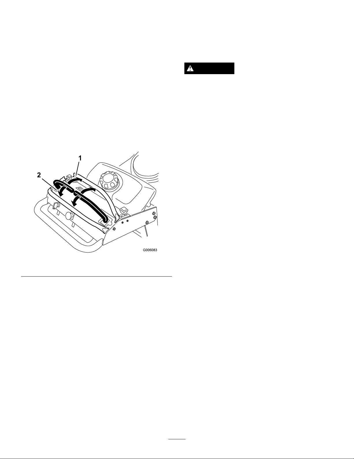
3.Togoforward,slowlypushthemotioncontrol
leversforward(Figure11).
Note:Theenginewillkillifthetractioncontrol
leversaremovedwiththeparkingbrakeengaged.
Togostraight,applyequalpressuretobothmotion
controllevers(
Toturn,movethemotioncontrollevertoward
neutralinthedirectionyouwanttoturn(Figure11).
Thefartheryoumovethetractioncontrolleversin
eitherdirection,thefasterthemachinewillmovein
thatdirection.
Tostop,pullthemotioncontrolleversbacktothe
neutralposition.
Figure11).
Settheparkingbrakewhenyouleavethemachine;refer
toSettingtheParkingBrakein
Remembertoremovethekeyfromtheignitionswitch.
Operation(page13).
CAUTION
Childrenorbystandersmaybeinjuredifthey
moveorattempttooperatethetractorwhileitis
unattended.
Alwaysremovetheignitionkeyandsettheparking
brakewhenleavingthemachineunattended,even
ifjustforafewminutes.
PushingtheMachinebyHand
Theby-passvalvesallowthemachinetobepushedby
handwithouttheenginerunning.
Important:Alwayspushthemachinebyhand.
Nevertowthemachinebecausehydraulicdamage
mayoccur.
Figure11
1.Forward2.Backward
DrivingBackward
1.Movetherightsidemotioncontrollevertothe
center,un-lockedposition.
2.Togobackward,slowlypullthemotioncontrol
leversrearward(Figure11).
Togostraight,applyequalpressuretobothmotion
controllevers(Figure11).
Toturn,releasepressureonthemotioncontrollever
towardthedirectionyouwanttoturn(Figure11).
ToPushtheMachine
1.DisengagethePTO,movethemotioncontrol
leverstotheneutrallockedpositionandsetthe
parkingbrake.
2.Opentheby-passvalveonbothpumpsbyturning
themcounterclockwise1to2turns.Thisallows
hydraulicuidtoby-passthepumpsandthewheels
toturn(
Note:Rotatetheby-passvalvesamaximumof2
turnssothevalvedoesnotcomeoutofthebody
causinguidtorunout.
Figure12).
Tostop,pushthemotioncontrolleverstothe
neutralposition.
StoppingtheMachine
Tostopthemachine,movethemotioncontrolleversto
neutral,movetherightsidemotioncontrolleverinto
17
Page 18
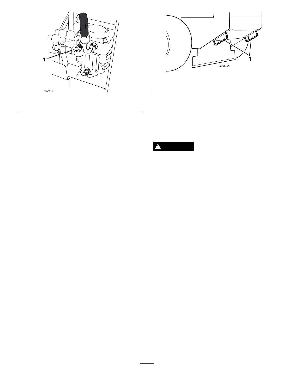
1.Pumpby-passvalve
Figure13
1.Tractionunittiedownloop
Figure12
SideDischargingorMulching
3.Releasetheparkingbrake.
4.Pushthemachinetothedesiredlocation.
5.Settheparkingbrake.
6.Closetheby-passvalves,butdonotovertighten
them.
Important:Donotstartoroperatethe
machinewiththeby-passvalvesopen.Damage
tosystemmayoccur.
TransportingMachines
Useaheavy-dutytrailerortrucktotransportthe
machine.Ensurethatthetrailerortruckhasall
necessarybrakes,lighting,andmarkingasrequiredby
law .Pleasecarefullyreadallthesafetyinstructions.
Knowingthisinformationcouldhelpyou,yourfamily,
petsorbystandersavoidinjury.
Totransportthemachine:
1.Ifusingatrailer,connectittothetowingvehicle
andconnectthesafetychains.
2.Ifapplicable,connectthetrailerbrakes.
theGrass
Thismowerhasahingedgrassdeectorthatdisperses
clippingstothesideanddowntowardtheturf.
DANGER
Withoutthegrassdeector,dischargecover,or
completegrasscatcherassemblymountedin
place,youandothersareexposedtobladecontact
andthrowndebris.Contactwithrotatingmower
blade(s)andthrowndebriswillcauseinjuryor
death.
•Neverremovethegrassdeectorfromthe
mowerbecausethegrassdeectorroutes
materialdowntowardtheturf.Ifthe
grassdeectoriseverdamaged,replaceit
immediately.
•Neverputyourhandsorfeetunderthemower.
•Nevertrytocleardischargeareaormower
bladesunlessyoureleasethebailandthepower
takeoff(PTO)isoff.Rotatetheignitionkeyto
Off.Alsoremovethekeyandpullthewire(s)
offthesparkplug(s).
3.Loadthemachineontothetrailerortruck.
4.Stoptheengine,removethekey,setthebrake,and
closethefuelvalve.
5.Usethemetaltiedownloopsonthemachineto
securelyfastenthemachinetothetrailerortruck
withstraps,chains,cable,orropes(
6.Fastenthefrontofthemachinetothetraileror
truckwithstraps,chains,cable,orropes.
Figure13).
AdjustingtheHeight-of-Cut
Theheight-of-cutcanbeadjustedfrom1to4-1/2
inch(25to114mm)in1/4inch(6mm)increments.
Adjustmentisdonebyrelocatingfourhairpincotter
pinsindifferentholelocationandbyaddingor
removingspacers.
Note:Allheight-of-cutpinsneedatleastonespacer
ordamagecanoccurtobushingifnoneareused.
Note:Allheight-of-cutpinscanusetwospacers
maximum.
18
Page 19
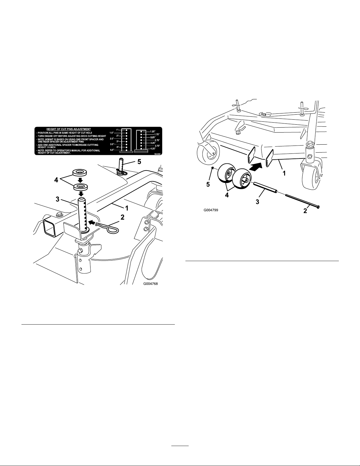
1.Selectholeinheight-of-cutpostandnumberof
spacerscorrespondingtotheheight-of-cutdesired
(Figure14).
2.Usingthelifthandle,raisesideofdeckandremove
hairpincotter(
Figure14).
3.Addorremovespacersifneededandthenalign
holesandinserthairpincotter(Figure14).
(10mm)clearanceabovetheground(Figure15,
Figure16,Figure17).
2.Ifadjustmentisneeded,removethebolt,washers
andnut(
Figure15,Figure16,Figure17).
3.Selectaholepositionsotheanti-scalprollersare
aminimumof3/8inch(10mm)offtheground
(Figure15,Figure16,Figure17).
Note:Spareheight-of-cutspacersmaybestored
onpostsandretainedbyahairpincotter.
Important:Allfourhairpincotterpinsmustbe
inthesameholelocationandwiththecorrect
numberofspacersforalevelcut.
4.Installtheboltandnut(Figure15,Figure16,
Figure17).
Figure15
40inch,48inch,and52inchMowerDecks
1.Mowerdeck
2.Bolt5.Nut
3.Spacer
4.Anti-ScalpRollers
Figure14
1.CarrierFrame4.Spacers
2.HairpinCotter5.Frontheight-of-cutpost
3.Backheight-of-cutpost
AdjustingtheAnti-Scalp
Rollers
Theanti-scalprollersneedtobeadjustedintheproper
holelocationforeachheight-of-cutposition.There
needstobe3/8inch(10mm)minimumclearance
abovetheground.
Note:Iftheanti-scalprollersareadjustedtoolowit
cancauseexcesswearoftherollers.
1.Afteradjustingheight-of-cut,checktheanti-scalp
rollerssothatthereisaminimumof3/8inch
19
Page 20
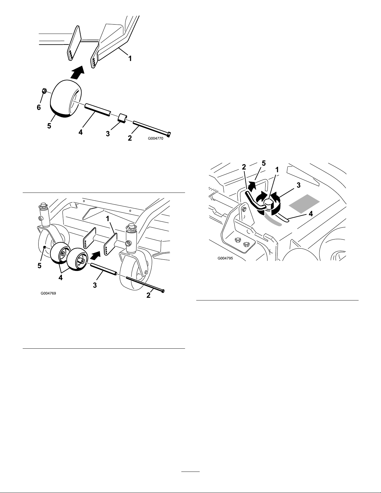
Figure16
40inch,48inch,and52inchMowerDecks
1.Mowerdeck4.Bushing
2.Bolt
3.Spacer
5.Anti-ScalpRollers
6.Nut
1.DisengagethePTO,movethemotioncontrol
leverstotheneutrallockedpositionandsetthe
parkingbrake.
2.Stoptheengine,removethekey,andwaitforall
movingpartstostopbeforeleavingtheoperating
position.
3.Toadjustthecamlock,swingtheleveruptoloosen
thecamlock(
Figure18).
4.Adjustthebafeandcamlockintheslottothe
desireddischargeow .
5.Swingtheleverbackovertotightenthebafeand
camlock(
Figure18).
6.Ifthecamdoesnotlockthebafeintoplaceoritis
tootight,loosentheleverandthenrotatethecam
lock.Adjustthecamlockuntilthedesiredlocking
pressureisachieved.
Figure17
36inchMowerDeck
1.Mowerdeck
2.Bolt5.Nut
3.Spacer
4.Anti-ScalpRollers
5.Incertainmowingconditionsandterrain,a
mismatchofcuttingheightmaybeseen.Adjusting
theoutsideanti-scalprollerstotheminimumsetting
of3/8inch(10mm)willhelppreventthemower
deckcuttingtoolowontheoutsideandminimize
themismatch.
AdjustingtheFlowBafe
Themowerdischargeowcanbeadjustedfordifferent
typesofmowingconditions.Positionthecamlockand
bafetogivethebestqualityofcut.
Figure18
1.Camlock
2.Lever
3.Rotatecamtoincreaseor
decreaselockingpressure
4.Slot
PositioningtheFlowBafe
Thefollowingguresareonlyrecommendationsfor
use.Adjustmentswillvarybygrasstype,moisture
content,andheightofgrass.
Note:Iftheenginepowerdrawsdownandthemower
groundspeedisthesame,openupthebafe.
PositionA
Thisisthefullrearposition(seeFigure19).The
suggesteduseforthispositionisafollows.
•Useforshort,lightgrassmowingconditions.
•Useindryconditions.
•Forsmallergrassclippings.
•Propelsgrassclippingsfartherawayfromthe
mower.
20
Page 21
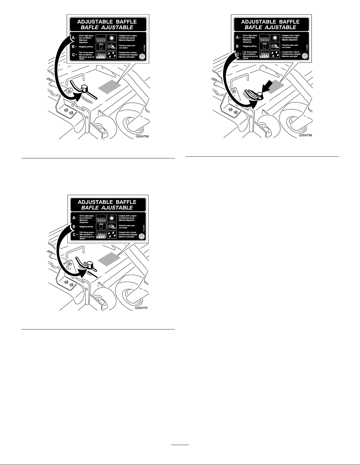
Figure19
PositionB
Usethispositionwhenbagging(Figure20).
Figure21
Figure20
PositionC
Thisisthefullopenposition.Thesuggestedusefor
thispositionisasfollows(Figure21).
•Useintall,densegrassmowingconditions.
•Useinwetconditions.
•Lowerstheenginepowerconsumption.
•Allowsincreasedgroundspeedinheavyconditions.
•ThispositionissimilartothebenetsoftheToro
SFSmower.
21
Page 22
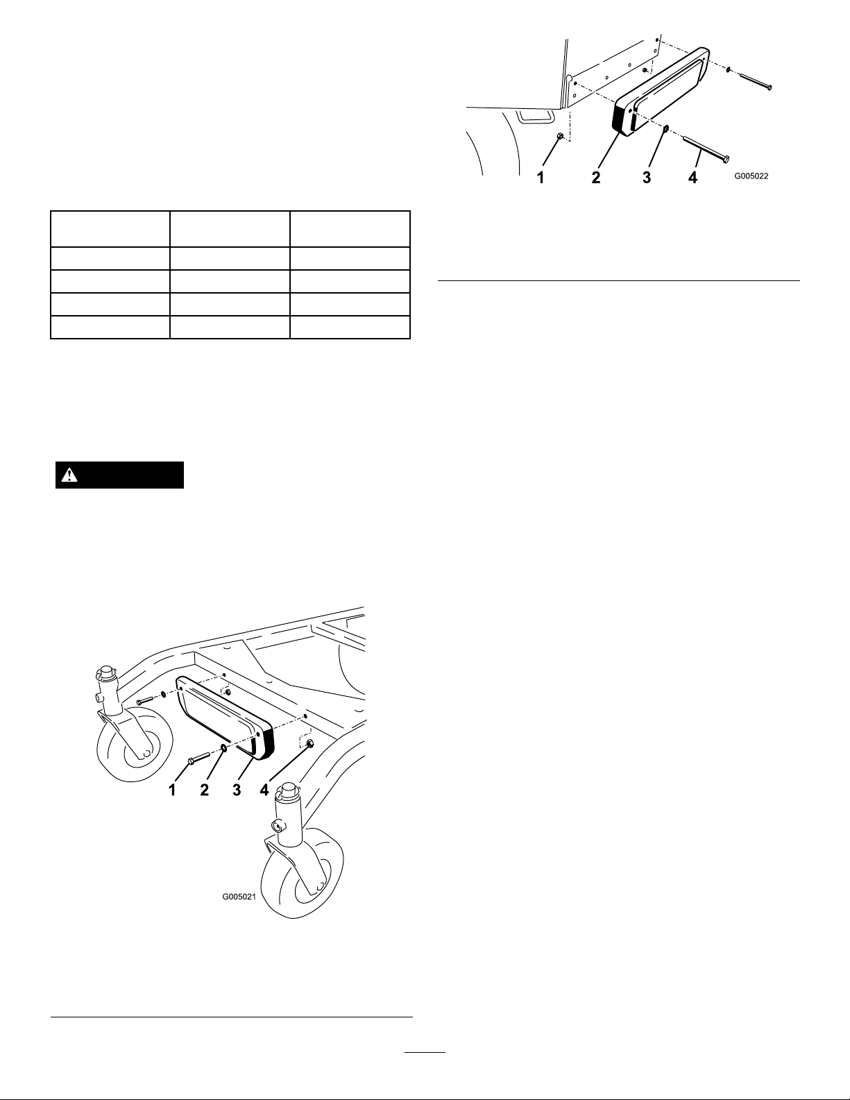
UsingtheMid-SizeWeight
Weightsareinstalledoncertainmowerstoimprove
balanceandimproveperformance.Theweightscanbe
movedorremovedtocreateoptimizedperformance
underdifferentmowingconditionsandforoperator
preference(Figure22orFigure23).
Thefollowingtableindicatesthepositionoftheweight
asinstalledatthefactory.
MowerDeckSizeNumberofweights
36inches1Front
40inches1Front
48inches
52inches1Rear
install
nonenone
•Anyrearweightmustberemovedwhena
Tru–Track
•WhenaTru–Track
®
Sulkyisinstalled.
®
Sulkyisinstalledfrontweights
areneeded.ContactanAuthorizedServiceDealer
forthecorrectquantityofweightsandplacement.
Positionofthe
weight
Figure23
Installingtherearweight.
1.Nut3.Washer
2.Weight4.Bolt
WARNING
Thefrontendofthemachinecanrapidlyriseup
whenthemowerisremoved.Thiscouldcause
seriousinjurytoyouorbystanders.
Supporttherearofthemachinewhenremoving
themowerfromthecarrierframe.
Figure22
Installingthefrontweight.
1.Bolt3.Weight
2.Washer4.Nut
22
Page 23

Maintenance
Note:Determinetheleftandrightsidesofthemachinefromthenormaloperatingposition.
RecommendedMaintenanceSchedule(s)
MaintenanceService
Interval
Aftertherst8hours
Beforeeachuseordaily
Every25hours
Every50hours
Every100hours
MaintenanceProcedure
•Changetheengineoil.
•Checkthehydraulicuidlevel.
•Changethehydrauliclter.
•Checkthesafetyinterlocksystem.
•Greasethefrontcasterpivotbearing.
•Checktheengineoillevel.
•Cleantheairintakescreen.
•Checkthebrakes.
•Inspecttheblades.
•Cleanthemowerdeck.
•Cleanfoamaircleanerelement.
•Checkthebatteryelectrolytelevel.
•Checkthehydraulicuidlevel.
•Greasethesidebearings.
•GreasethePTObeltidler.
•Greasethemowerdeckbeltidler.
•Checkthepaperaircleanerelement.
•Checkthetirepressure.
•Checkthemowerbelt.
•CheckthePTOdrivebelt.
•Checkthepumpdrivebelt.
•Changetheengineoil.
•Checkthesparkplugs.
•Adjusttheelectricclutch.
•Checkthehydrauliclines.
•Replacethepaperaircleanerelement.
Every200hours
Every250hours
Every400hours
Every500hours
Beforestorage
Important:Refertoyour
•Changetheoillter.
•Replacethefuellter.
•Replacethefuelventlter.
•ChangethehydrauliclterandhydraulicoilwhenusingMobil®1oil.
•Greasethefrontwheelbearings(moreoftenindirtyordustyconditions).
•ChangethehydrauliclterandhydraulicoilwhenusingT oro®HYPR-OIL™500
hydraulicoil.
•Paintchippedsurfaces.
•Performallmaintenanceprocedureslistedabovebeforestorage.
Engine Operator’ s Man ual
foradditionalmaintenanceprocedures.
CAUTION
Ifyouleavethekeyintheignitionswitch,someonecouldaccidentlystarttheengineandseriouslyinjure
youorotherbystanders.
Removethekeyfromtheignitionanddisconnectthesparkplugwiresfromthesparkplugsbeforeyoudo
anymaintenance.Setthewiresasidesothattheydonotaccidentallycontactthesparkplugs.
23
Page 24
Lubrication
g014655
g014675
GreasingthePTODriveBelt
GreasewithNo.2generalpurposelithiumbaseor
molybdenumbasegrease.
HowtoGrease
1.DisengagethePTOandsettheparkingbrake.
2.Stoptheengine,removethekey,andwaitforall
movingpartstostopbeforeleavingtheoperating
position.
3.Cleanthegreasettingswitharag.Makesureto
scrapeanypaintoffthefrontofthetting(s).
4.Connectagreaseguntothetting.Pumpgrease
intothettingsuntilgreasebeginstooozeoutof
thebearings.
5.Wipeupanyexcessgrease.
LubricatingtheBearings
ServiceInterval:Beforeeachuseordaily
IdlerandMowerDeckBelt
Idler
ServiceInterval:Every50hours
Every50hours
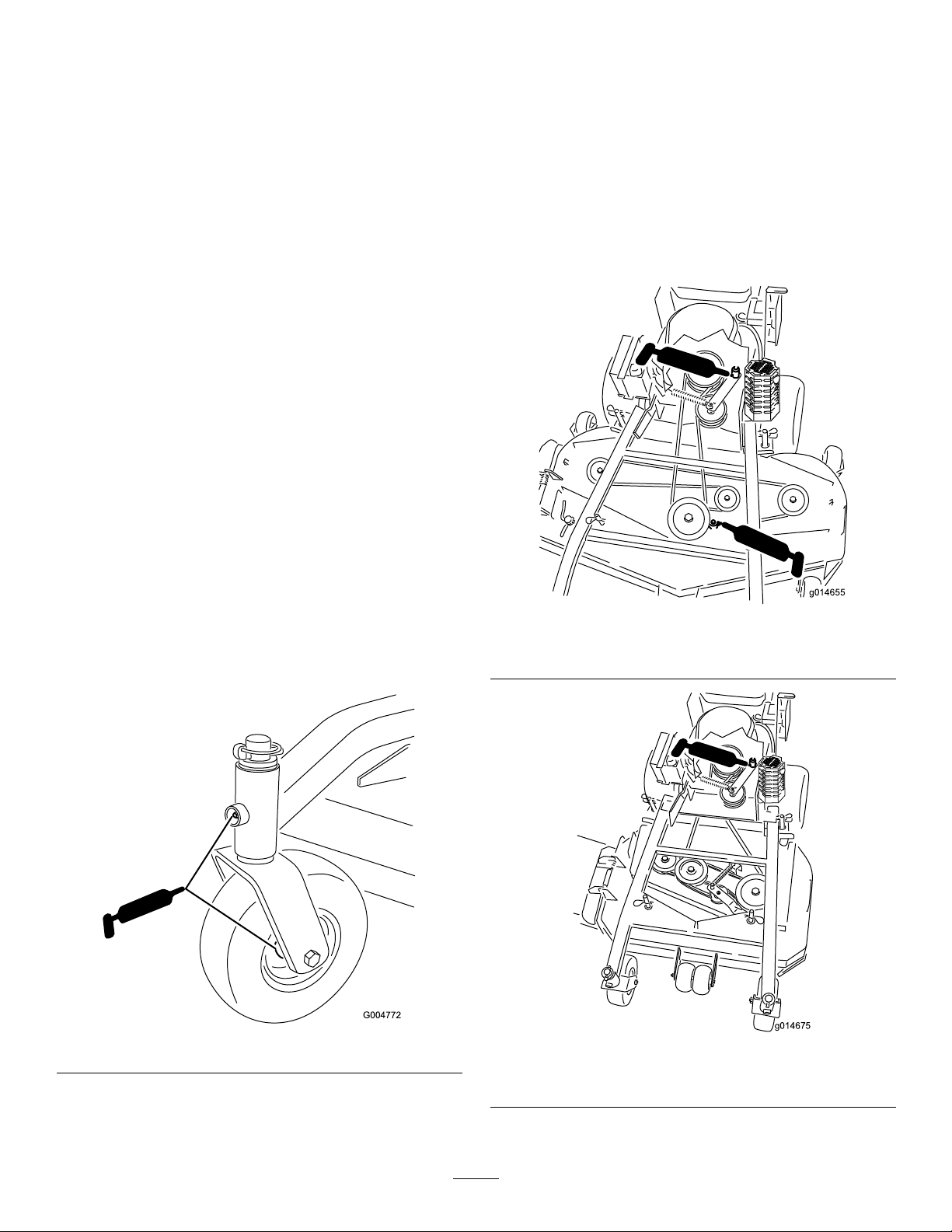
Greasetheidlerpulleypivots(Figure25orFigure26).
Note:Youwillhavetoremovethecarriercoversto
accessthegreasettingforthemowerdeck.
Every400hours
Every50hours
Lubricatethefrontcasterwheelbearingsandfront
pivots(Figure24).
Note:Makesuretherearwheelgreasecapsare
removedbeforelubricatingrearwheels.
Figure25
40inch,48inch,and52inchMowerDeckshown
Figure24
Figure26
36inchMowerDeckshown
24
Page 25
EngineMaintenance
ServicingtheAirCleaner
ServiceInterval/Specication
ServiceInterval:Every25hours—Cleanfoamair
cleanerelement.
Every50hours—Checkthepaperair
cleanerelement.
Every200hours—Replacethepaper
aircleanerelement.
Note:Servicetheaircleanermorefrequently(every
fewoperatinghours)iftheoperatingconditionsare
extremelydustyorsandy .
Important:Donotoilthefoamorpaperelement.
RemovingtheFoamandPaper
Elements
1.DisengagethePTOandsettheparkingbrake.
2.Stoptheengine,removethekey,andwaitforall
movingpartstostopbeforeleavingtheoperating
position.
3.Cleanaroundtheaircleanertopreventdirt
fromgettingintotheengineandcausingdamage
Figure27).
(
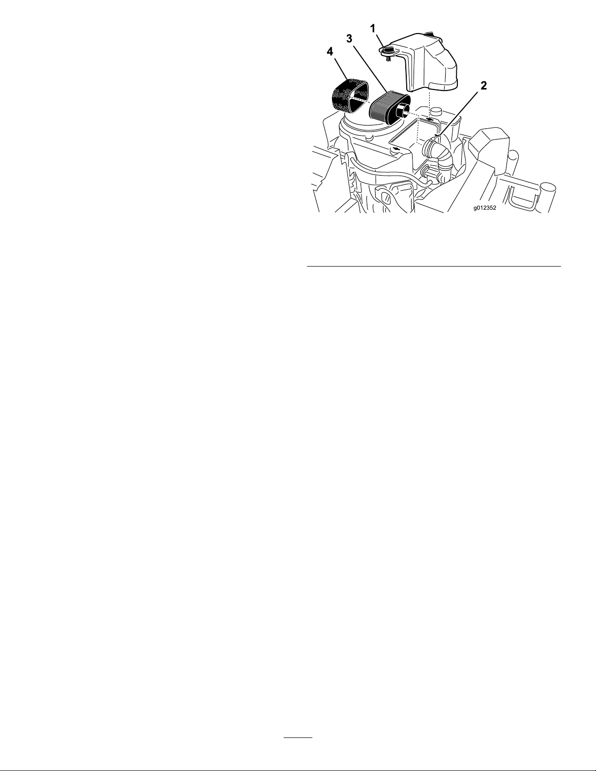
4.Unscrewthecoverknobsandremovetheaircleaner
cover(
5.Unscrewthehoseclampandremovetheaircleaner
assembly(Figure27).
6.Carefullypullthefoamelementoffthepaper
element(Figure27).
Figure27).
Figure27
1.Cover
2.Hoseclamp4.Foamelement
3.Paperelement
CleaningtheFoamAirCleanerElement
1.Washthefoamelementinliquidsoapandwarm
water.Whentheelementisclean,rinseitthoroughly.
2.Drytheelementbysqueezingitinacleancloth.
Important:Replacethefoamelementifitis
tornorworn.
ServicingthePaperAirCleaner
Element
1.Donotcleanthepaperlter,replaceit(Figure27).
2.Inspecttheelementfortears,anoilylm,ordamage
totherubberseal.
3.Replacethepaperelementifitisdamaged.
InstallingtheFoamandPaperElements
Important:Topreventenginedamage,always
operatetheenginewiththecompletefoamand
paperaircleanerassemblyinstalled.
1.Carefullyslidethefoamelementontothepaperair
cleanerelement(Figure27).
2.Placetheaircleanerassemblyontotheaircleaner
baseandsecureitwiththe2wingnuts(Figure27).
3.Placetheaircleanercoverintopositionandtighten
thecoverknob(Figure27).
25
Page 26
ServicingtheEngineOil
ServiceInterval/Specication
ServiceInterval:Beforeeachuseordaily—Checkthe
engineoillevel.
Aftertherst8hours—Changethe
engineoil.
Every100hours—Changetheengine
oil.
Every200hours—Changetheoil
lter.
Note:Changetheoilmorefrequentlywhenthe
operatingconditionsareextremelydustyorsandy.
OilType:Detergentoil(APIserviceSF ,SG,SH,SJ
orSL)
CrankcaseCapacity:58ounces(1.7liter)withthelter
removed;51ounces(1.5liter)withoutthelterremoved
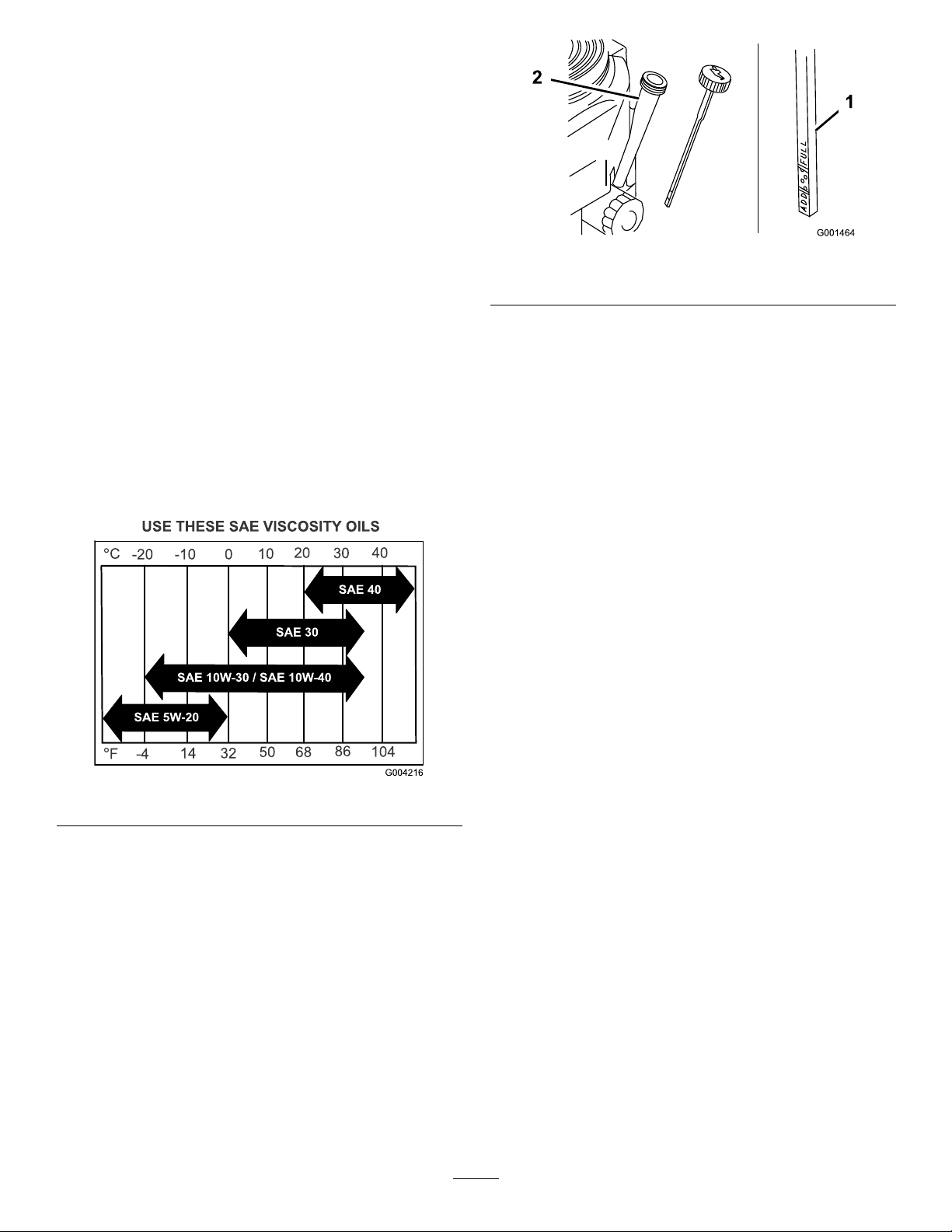
Figure29
1.Oildipstick
2.Fillertube
5.Unscrewtheoildipstickandwipetheendclean
(Figure29).
6.Slidetheoildipstickfullyintothellertube,butdo
notthreadontotube(Figure29).
7.Pullthedipstickoutandlookattheend.Iftheoil
levelislow ,slowlypouronlyenoughoilintotheller
tubetoraisetheleveltotheFullmark.
Viscosity:Refertothetable(
Figure28
Figure28).
CheckingtheEngineOilLevel
1.Parkthemachineonalevelsurface.
2.DisengagethePTOandsettheparkingbrake.
3.Stoptheengine,removethekey,andwaitforall
movingpartstostopbeforeleavingtheoperating
position.
4.Cleanaroundtheoildipstick(
cannotfallintothellerholeanddamagetheengine.
Figure29)sothatdirt
Important:Donotoverllthecrankcasewith
oilandruntheengine;enginedamagecan
result.
ChangingtheEngineOil
1.Starttheengineandletitrunveminutes.This
warmstheoilsoitdrainsbetter.
2.Parkthemachinesothatthedrainsideisslightly
lowerthantheoppositesidetoassuretheoildrains
completely.
3.DisengagethePTOandsettheparkingbrake.
4.Stoptheengine,removethekey,andwaitforall
movingpartstostopbeforeleavingtheoperating
position.
5.Slidethedrainhoseovertheoildrainvalve.
6.Placeapanbelowthedrainhose.Rotateoildrain
valvetoallowoiltodrain(
7.Whenoilhasdrainedcompletely,closethedrain
valve.
8.Removethedrainhose(Figure30).
Note:Disposeoftheusedoilatarecyclingcenter.
Figure30).
26
Page 27
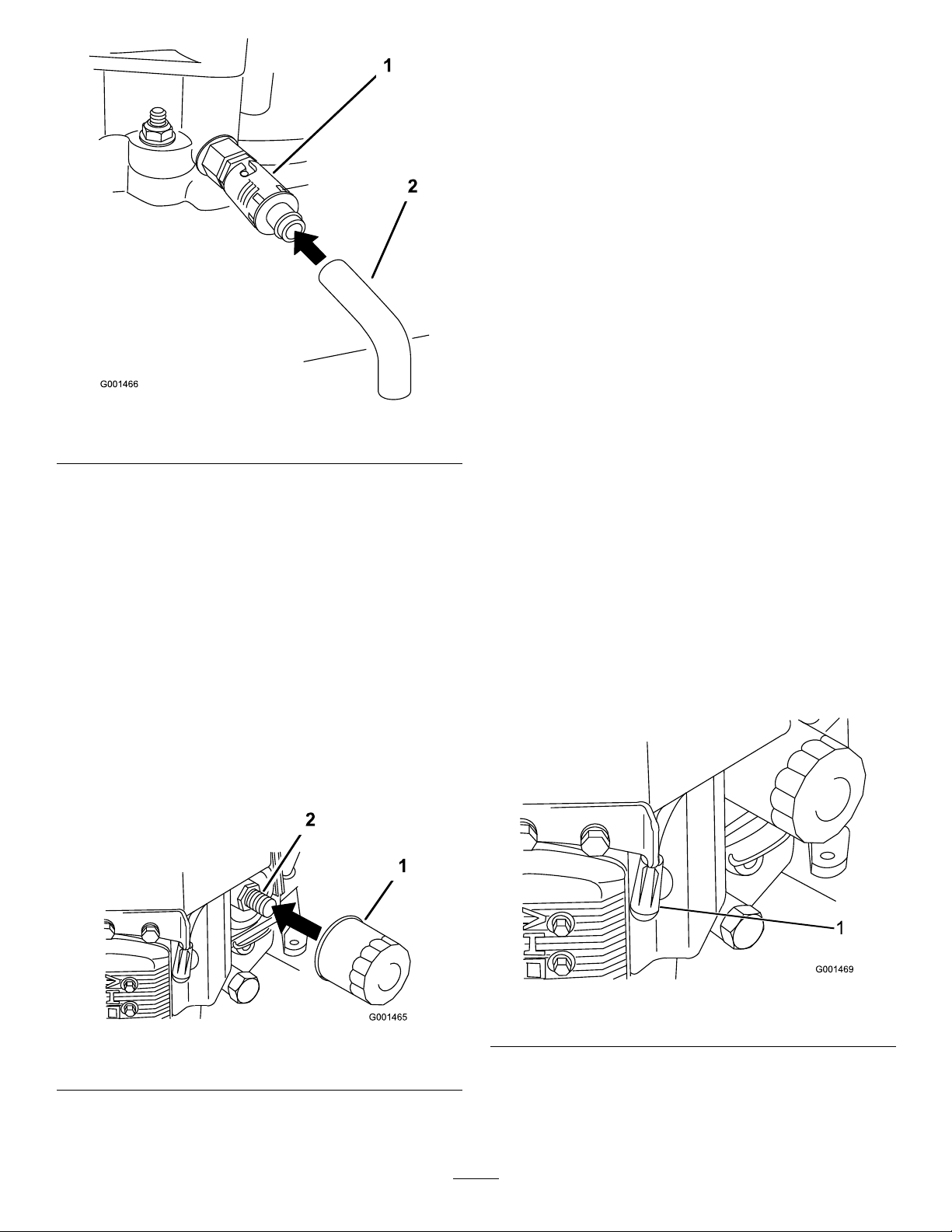
Figure30
1
1.Oildrainvalve2.Oildrainhose
9.Slowlypourapproximately80%ofthespeciedoil
intothellertube(Figure29).
10.Checktheoillevel;refertoCheckingtheEngineOil
Level.
11.SlowlyaddtheadditionaloiltobringittotheFull
mark.
ChangingtheOilFilter
Note:Changetheoilltermorefrequentlywhenthe
operatingconditionsareextremelydustyorsandy.
4.Installthereplacementoilltertothelteradapter,
turntheoillterclockwiseuntiltherubbergasket
contactsthelteradapter,thentightenthelteran
additional3/4turn(
Figure31).
5.Fillthecrankcasewiththepropertypeofnewoil;
refertoServicingtheEngineOil.
6.Runtheengineforabout3minutes,stoptheengine,
andcheckforoilleaksaroundtheoillteranddrain
valve.
7.Checktheengineoillevelandaddoilifneeded.
8.Wipeupanyspilledoil.
ServicingtheSparkPlugs
ServiceInterval:Every100hours
Ensurethattheairgapbetweenthecenterandside
electrodesiscorrectbeforeinstallingthesparkplug.
Useasparkplugwrenchforremovingandinstallingthe
sparkplugsandagappingtool/feelergaugetocheckand
adjusttheairgap.Installanewsparkplugsifnecessary.
Type:Champion®RCJ8YorequivalentAirGap:
0.030inch(0.75mm)
RemovingtheSparkPlugs
1.DisengagethePTOandsettheparkingbrake.
2.Stoptheengine,removethekey,andwaitforall
movingpartstostopbeforeleavingtheoperating
position.
3.Disconnectthewiresfromthesparkplugs
(Figure32).
1.Draintheoilfromtheengine;refertoChangingthe
EngineOil.
2.Removetheoldlter(
1.Oillter
Figure31).
Figure31
2.Adapter
3.Applyathincoatofnewoiltotherubbergasketon
thereplacementlter(Figure31).
Figure32
1.Spark-plugwire/sparkplug
4.Cleanaroundthesparkplugstopreventdirtfrom
fallingintotheengineandpotentiallycausing
damage.
5.Removethesparkplugsandthemetalwashers.
27
Page 28
CheckingtheSparkPlugs
1.Lookatthecenterofthesparkplugs(Figure33).
Ifyouseelightbrownorgrayontheinsulator,the
engineisoperatingproperly .Ablackcoatingonthe
insulatorusuallymeansthattheaircleanerisdirty.
2.Ifneeded,cleanthesparkplugwithawirebrushto
removecarbondeposits.
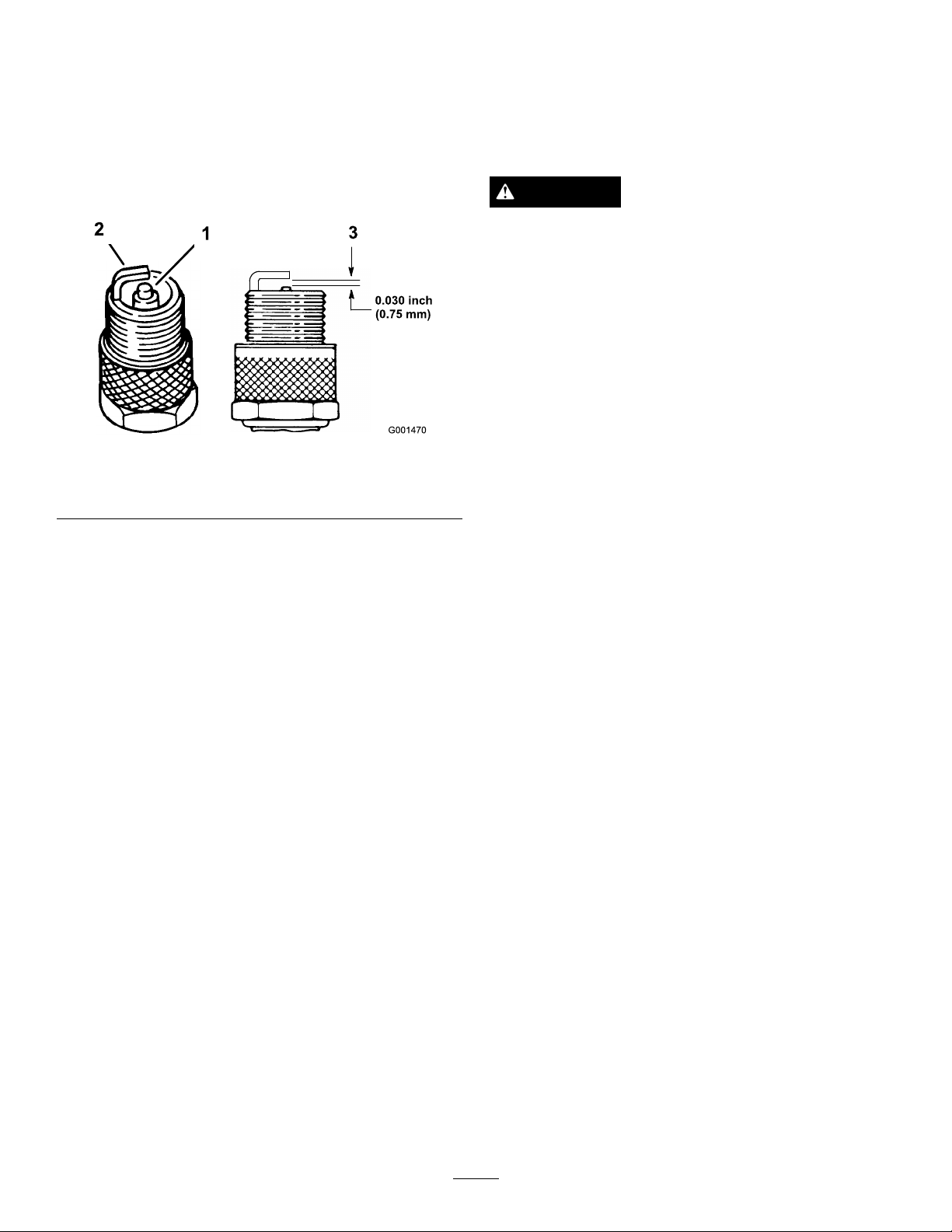
Figure33
1.Centerelectrodeinsulator3.Airgap(nottoscale)
2.Sideelectrode
Important:Alwaysreplacethesparkplugs
whenithaswornelectrodes,anoilylmonit,
orhascracksintheporcelain.
3.Checkthegapbetweenthecenterandsideelectrodes
Figure33).Bendthesideelectrode(Figure33)if
(
thegapisnotcorrect.
InstallingtheSparkPlugs
1.Installthesparkplugsandthemetalwasher.Ensure
thattheairgapissetcorrectly.
2.Tightenthesparkplugsto16ft-lb(22N-m).
3.Connectthewirestothesparkplugs(
Figure33).
FuelSystem
Maintenance
DrainingtheFuelTank
DANGER
Incertainconditions,gasolineisextremely
ammableandhighlyexplosive.Areorexplosion
fromgasolinecanburnyouandothersandcan
damageproperty.
•Draingasolinefromthefueltankwhenthe
engineiscold.Dothisoutdoorsinanopenarea.
Wipeupanygasolinethatspills.
•Neversmokewhendraininggasoline,andstay
awayfromanopenameorwhereasparkmay
ignitethegasolinefumes.
1.Parkthemachineonalevelsurface,toassurefuel
tankdrainscompletely.Thendisengagethepower
takeoff(PTO),settheparkingbrake,andturnthe
ignitionkeytooff.Removethekey.
2.Closethefuelshut-offvalveatthefueltank
Figure34).
(
3.Squeezetheendsofthehoseclamptogether
andslideitupthefuellineawayfromfuellter
Figure34).
(
4.Pullthefuellineoffthefuellter(Figure34).Open
thefuelshut-offvalveandallowthegasolinetodrain
intoagascanordrainpan.
Note:Nowisthebesttimetoinstallanewfuellter
becausethefueltankisempty.RefertoReplacing
theFuelFilter.
5.Installthefuellineontothefuellter.Slidethehose
clampclosetothevalvetosecurethefuelline.
6.Wipeupanyspilledfuel.
28
Page 29
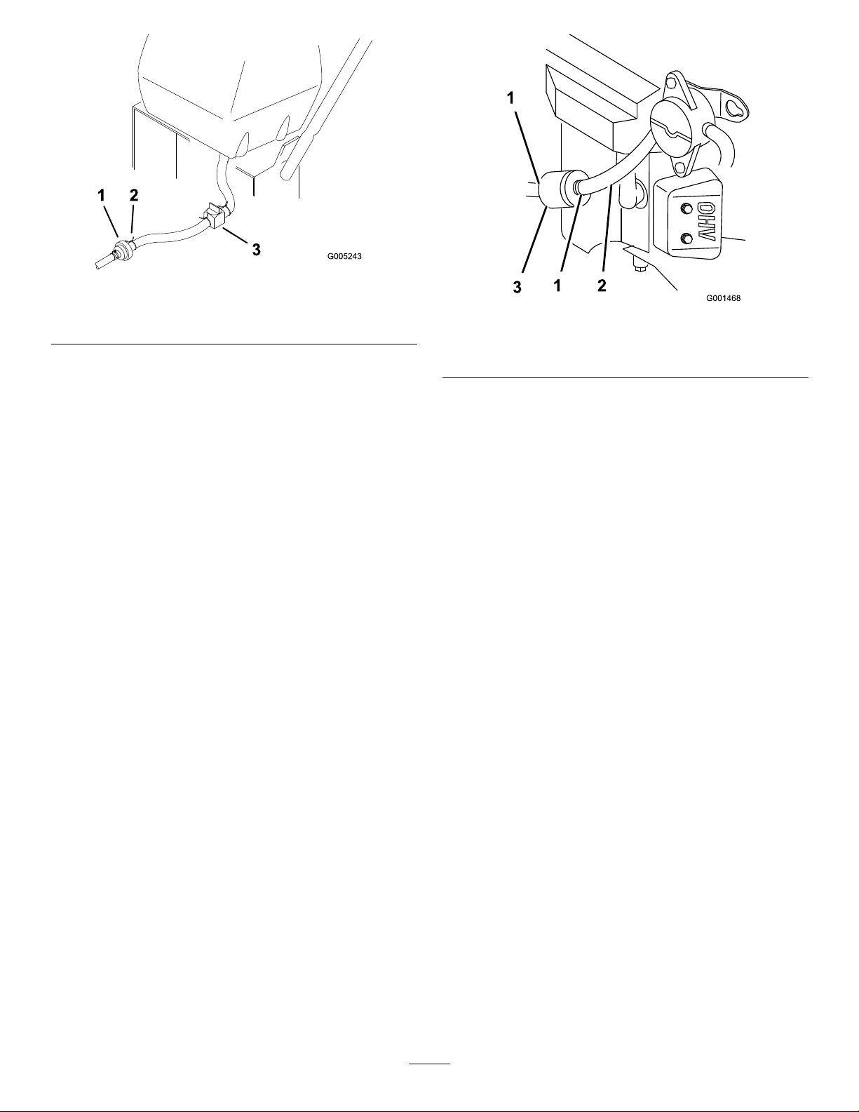
Figure34
1.Fuellter3.Fuelshut-offvalve
2.Clamp
Figure35
1.Hoseclamp3.Filter
2.Fuelline
ServicingtheFuelFilter
ServiceInterval:Every200hours/Yearly(whichever
comesrst)
ReplacingtheFuelFilter
Neverinstalladirtylterifitisremovedfromthefuel
line.
Note:Notehowthefuellterisinstalledinorderto
installthenewltercorrectly.
Note:Wipeupanyspilledfuel.
1.DisengagethePTOandsettheparkingbrake.
2.Stoptheengine,removethekey,andwaitforall
movingpartstostopbeforeleavingtheoperating
position.
3.Closefuelshut-offvalveatthefueltank(
4.Squeezetheendsofthehoseclampstogetherand
slidethemawayfromthelter(Figure35).
Figure34).
5.Removethelterfromthefuellines.
6.Installanewlterandmovethehoseclampsclose
tothelter.
7.Openfuelshut-offvalveatfueltank(
Figure34).
8.Checkforfuelleaksandrepairifneeded.
9.Wipeupanyspilledfuel.
ServicingtheFuelVentSystem
ServiceInterval:Every200hours/Yearly(whichever
comesrst)
1.DisengagethePTOandsettheparkingbrake.
2.Stoptheengine,removethekey,andwaitforall
movingpartstostopbeforeleavingtheoperating
position.
3.Removetheexistingfuelventlter(
4.Installanewlter.
Figure36).
29
Page 30
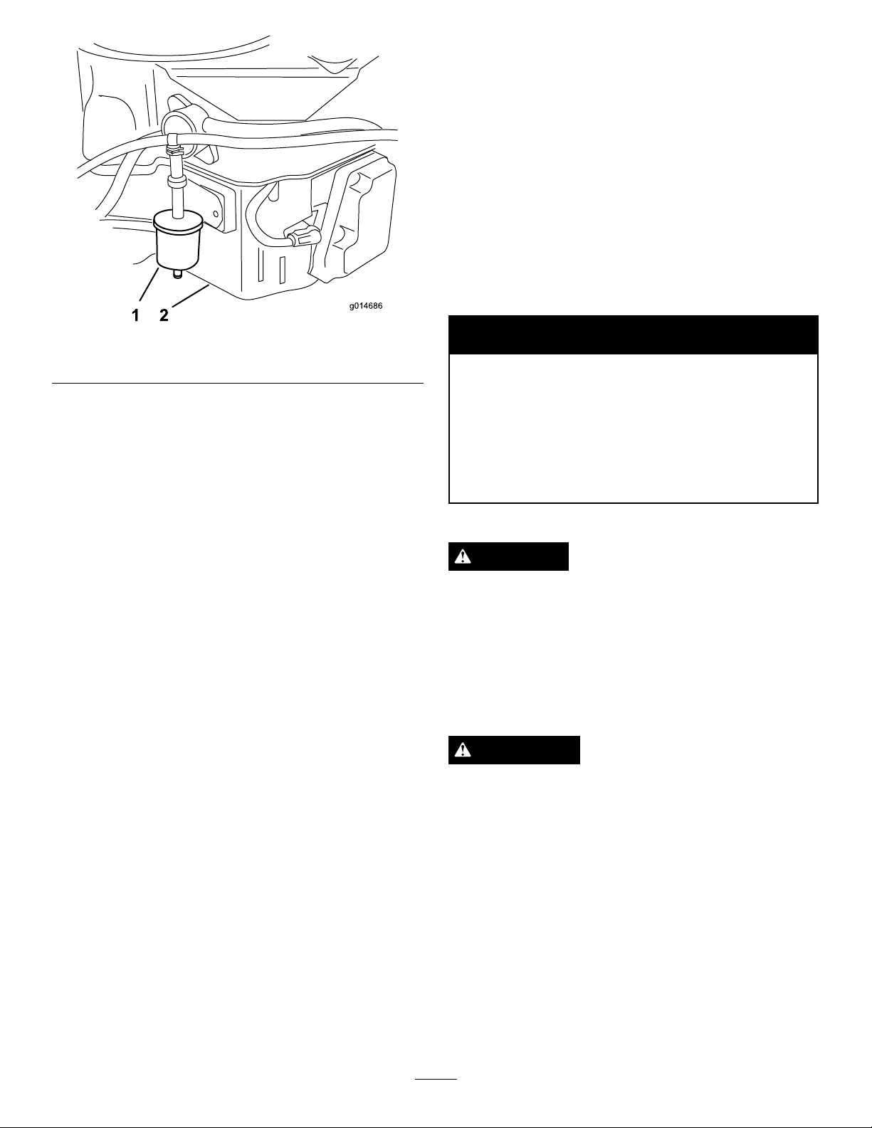
g014686
1 2
ElectricalSystem
Maintenance
ServicingtheBattery
Alwayskeepthebatterycleanandfullycharged.Use
apapertoweltocleanthebatterycase.Ifthebattery
terminalsarecorroded,cleanthemwithasolutionof
fourpartswaterandonepartbakingsoda.Applyalight
coatingofgreasetothebatteryterminalstoprevent
corrosion.
Voltage:12V
Figure36
1.Fuelventlter2.Rightsideofmotor
WARNING
CALIFORNIA
Proposition65Warning
Batteryposts,terminals,andrelated
accessoriescontainleadandleadcompounds,
chemicalsknowntotheStateofCalifornia
tocausecancerandreproductiveharm.
Washhandsafterhandling.
DANGER
Batteryelectrolytecontainssulfuricacidwhichisa
deadlypoisonandcausessevereburns.
Donotdrinkelectrolyteandavoidcontactwith
skin,eyesorclothing.Wearsafetyglassestoshield
youreyesandrubberglovestoprotectyourhands.
RemovingtheBattery
WARNING
Batteryterminalsormetaltoolscouldshortagainst
metalmachinecomponentscausingsparks.Sparks
cancausethebatterygassestoexplode,resulting
inpersonalinjury.
•Whenremovingorinstallingthebattery,donot
allowthebatteryterminalstotouchanymetal
partsofthemachine.
•Donotallowmetaltoolstoshortbetween
thebatteryterminalsandmetalpartsofthe
machine.
30
Page 31
WARNING
g012916
7
6
5
4
3
2
1
8
9
10
11
Incorrectbatterycableroutingcoulddamagethe
machineandcablescausingsparks.Sparkscan
causethebatterygassestoexplode,resultingin
personalinjury.
•AlwaysDisconnectthenegative(black)battery
cablebeforedisconnectingthepositive(red)
cable.
•AlwaysReconnectthepositive(red)battery
cablebeforereconnectingthenegative(black)
cable.
1.DisengagethePTOandsettheparkingbrake.
2.Stoptheengine,removethekey,andwaitforall
movingpartstostopbeforeleavingtheoperating
position.
3.Lifttheblackrubbercoveronthenegativecable.
Disconnectthenegativebatterycablefromthe
negative(-)batteryterminal(
4.Slidetheredterminalbootoffthepositive(red)
batteryterminal.Thenremovethepositive(red)
batterycable(Figure37).
5.Removethebatteryholddownplate(
removethebattery.
Figure37).
Figure37)and
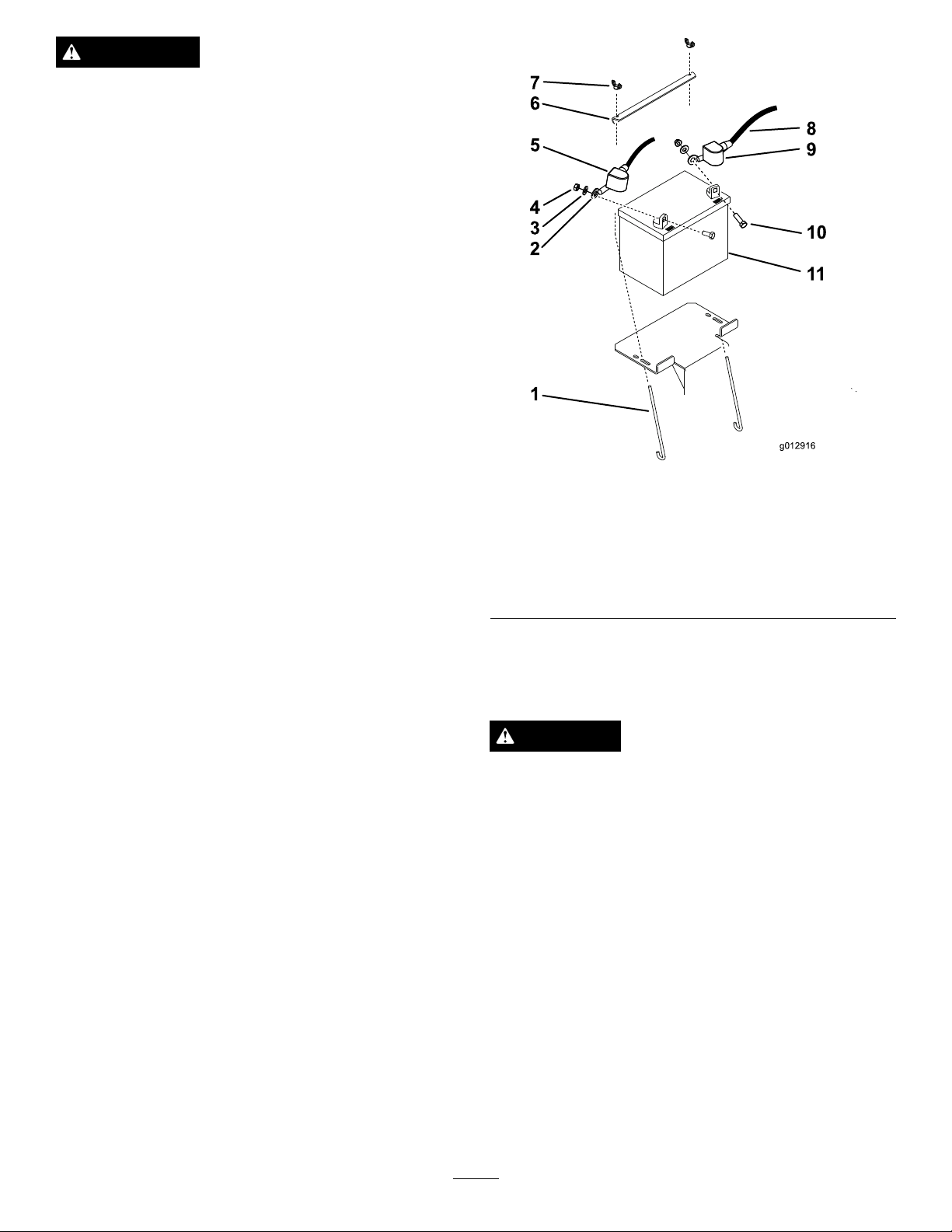
Figure37
1.J-bolt7.Wingnut
2.Positivecable8.Negativecable
3.Washer
4.Nut(5/16inch)
5.Rubbercover(red)
6.Batteryholddown
9.Rubbercover(black)
10.Bolt
11.Battery
InstallingtheBattery
1.Placethebatterontothemachine(Figure37).
2.Securethebatterywiththeholddownplate,j-bolts,
andlocknuts.
3.First,installthepositive(red)batterycableto
positive(+)batteryterminalwithanut,washerand
Figure37).Slidetherubbercoveroverthepost.
bolt(
4.Theninstallthenegativebatterycableandground
wiretothenegative(-)batteryterminalwithanut,
washerandbolt(
overthepost.
Figure37).Slidetherubbercover
CheckingtheBatteryElectrolyteLevel
ServiceInterval:Every25hours
DANGER
Batteryelectrolytecontainssulfuricacidwhichisa
deadlypoisonandcausessevereburns.
•Donotdrinkelectrolyteandavoidcontactwith
skin,eyesorclothing.Wearsafetyglassesto
shieldyoureyesandrubberglovestoprotect
yourhands.
•Fillthebatterywherecleanwaterisalways
availableforushingtheskin.
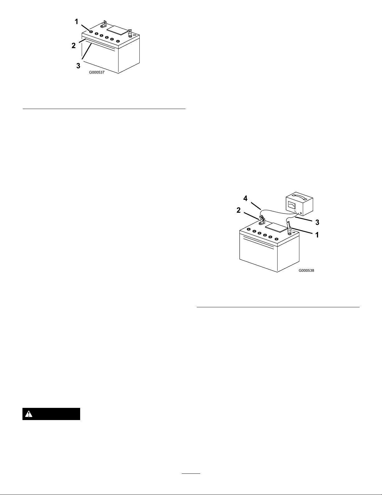
1.Lookatthesideofthebattery.Theelectrolytemust
beuptotheupperline(
electrolytetofallbelowtheLowerline(Figure38).
Figure38).Donotallowthe
31
Page 32
Important:Alwayskeepthebatteryfullycharged
(1.265specicgravity).Thisisespeciallyimportant
topreventbatterydamagewhenthetemperatureis
below32°F(0°C).
1.Removethebatteryfromthechassis;referto
RemovingtheBattery.
Figure38
1.Ventcaps3.Lowerline
2.Upperline
2.Iftheelectrolyteislow,addtherequiredamountof
distilledwater;refertoAddingW atertotheBattery
inElectricalSystemMaintenance(page30).
AddingWatertotheBattery
Thebesttimetoadddistilledwatertothebatteryisjust
beforeyouoperatethemachine.Thisletsthewatermix
thoroughlywiththeelectrolytesolution.
1.Removethebatteryfromthemachine;
refertoRemovingtheBatteryin
ElectricalSystemMaintenance(page30).
Important:Neverllthebatterywithdistilled
waterwhilethebatteryisinstalledinthe
machine.Electrolytecouldbespilledonother
partsandcausecorrosion.
2.Checktheelectrolytelevel;refertoCheckingthe
ElectrolyteLevel.
3.Makesurethellercapsareinstalledinbattery.
Chargebatteryfor1hourat25to30ampsor6
hoursat4to6amps.
4.Whenthebatteryisfullycharged,unplugthecharger
fromtheelectricaloutlet,thendisconnectthe
chargerleadsfromthebatteryposts(
Figure39).
5.Installthebatteryontothemachineandconnectthe
batterycables,refertoInstallingtheBattery.
Note:Donotrunthemachinewiththebattery
disconnected,electricaldamagemayoccur.
2.Cleanthetopofthebatterywithapapertowel.
3.Removetheventcapsfromthebattery(
Figure38).
4.Slowlypourdistilledwaterintoeachbatterycell
untiltheelectrolytelevelisuptotheUpperline
Figure38)onthebatterycase.
(
Important:Donotoverllthebatterybecause
electrolyte(sulfuricacid)cancausesevere
corrosionanddamagetothechassis.
5.Waitvetotenminutesafterllingthebatterycells.
Adddistilledwater,ifnecessary,untiltheelectrolyte
levelisuptotheUpperline(
Figure38)onthe
batterycase.
6.Reinstallthebatteryventcaps.
ChargingtheBattery
WARNING
Chargingthebatteryproducesgassesthatcan
explode.
Figure39
1.PositiveBatteryPost
2.NegativeBatteryPost
3.Red(+)ChargerLead
4.Black(-)ChargerLead
ServicingtheFuses
Theelectricalsystemisprotectedbyfuses.Itrequires
nomaintenance.Ifafuseblows,checkthecomponent
orcircuitforamalfunctionorshort.
1.Removethecoverunderthecontrolpanel.
2.Pulloutonthefusetoremoveorreplaceit
(Figure40).
3.Installthecoverunderthecontrolpanel.
Note:Ensurethecorrectsizefuseisinstallwiththe
correctwirecolorasshowninFigure40.
Neversmokenearthebatteryandkeepsparksand
amesawayfrombattery.
32
Page 33
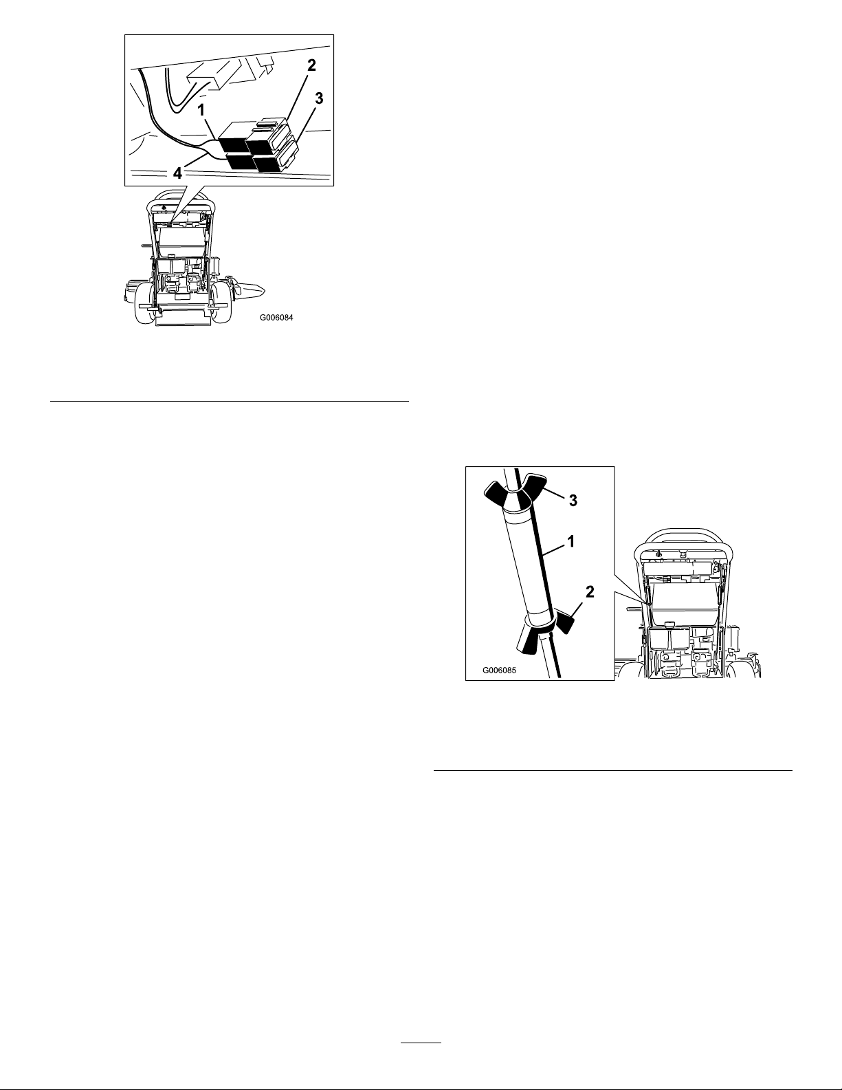
Figure40
1.Redwire3.Fuse,25amp,bladetype
2.Fuse,30amp,bladetype4.Violetwire
DriveSystem
Maintenance
AdjustingtheTracking
1.Ifthemachinedoesnottrackstraight,adjustment
isrequired.
2.Checkthereartirepressure.RefertoCheckingthe
TirePressure.
3.Loosenthewingnutsontherightcontrolrodand
rotatetheturnbuckleinorouttoensuretheright
sidecontrolleveriscenteredintheneutrallock
position.Securetheturnbuckleinpositionwiththe
wingnuts(
4.Loosenthewingnutsontheleftcontrolrodand
rotatetheturnbuckleinorouttochangethetracking.
Securetheturnbuckleinpositionwiththewingnuts
(Figure41).
5.Checkforpropertracking.Adjusttheleftcontrol
rodifachangeisneeded.
Figure41).
Figure41
1.Turnbuckle
2.Bottomwingnut
3.Topwingnut(lefthand
threaded)
CheckingtheTirePressure
ServiceInterval:Every50hours/Monthly(whichever
comesrst)
Checkthepressureatthevalvestem(
33
Figure42).
Page 34
Maintaintheairpressureinthereartiresat12-14psi
(83-97kPa).Uneventirepressurecancauseanuneven
cut.
Note:Thefronttiresaresemi-pneumatictiresanddo
notrequireairpressuremaintenance.
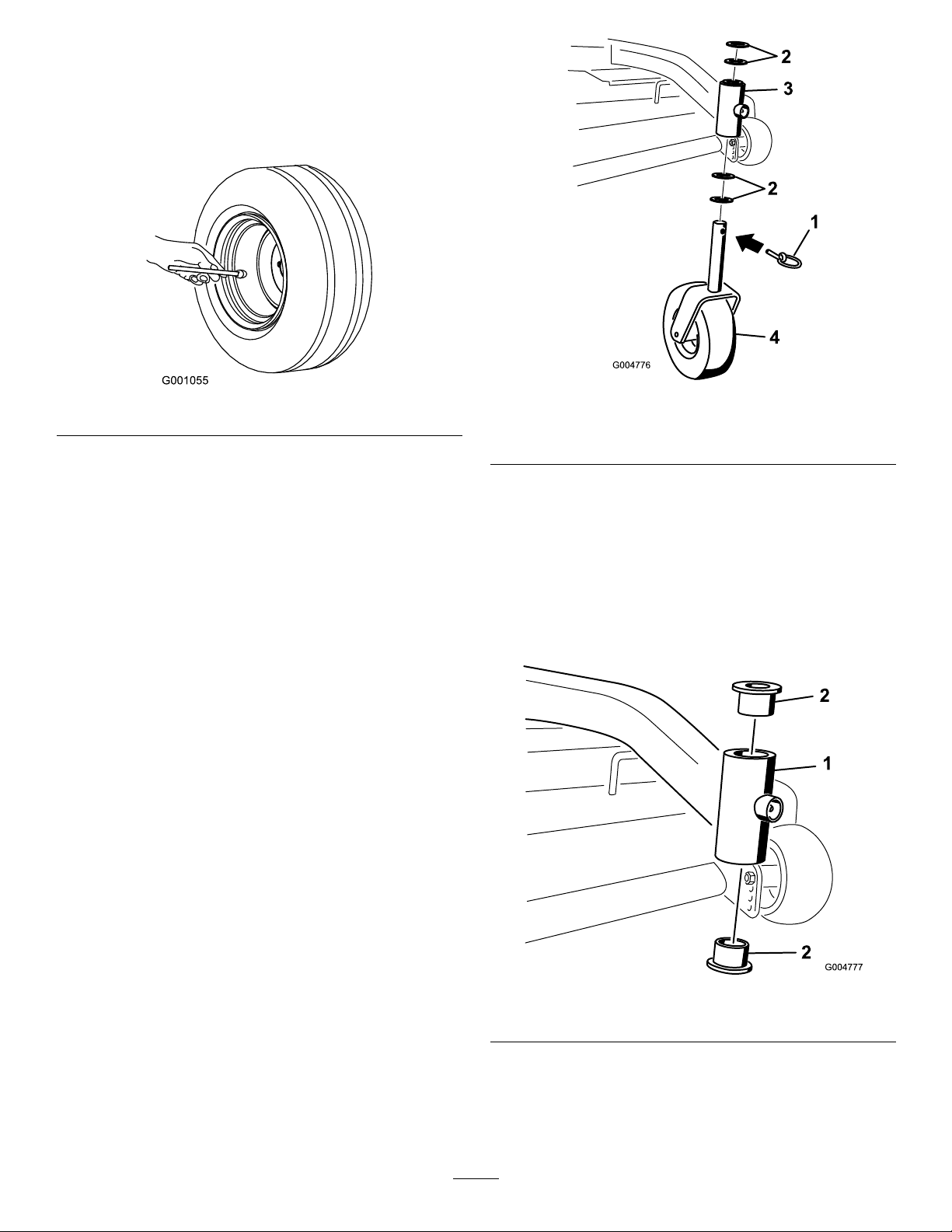
Figure42
ReplacingtheCasterWheel
ForkBushings
Thecasterwheelforksaremountedinbushingspressed
intothetopandbottomofthecarrierframemounting
pivottubes.Tocheckthebushings,movethecaster
forksbackandforthandside-to-side.Ifacasterforkis
loose,thebushingsarewornandmustbereplaced.
1.Raisethecuttingunitsothecasterwheelsareoff
theoor,thensupportthefrontofthemowerwith
jackstands.
2.Removethelockingpinandspacer(s)fromthetop
ofthecasterwheelfork(
Figure43).
Figure43
1.LockingPin
2.Spacers4.Casterwheelfork
3.Carrierframepivottube
3.Pullthecasterwheelforkoutofthemountingtube,
leavingthespacer(s)onthebottomofthefork.
Rememberthelocationofthespacersoneachfork
toensurecorrectinstallation,andtomaintainalevel
deck.
4.Insertapinpunchintothemountingtubeand
carefullydriveoutthebushings(
Figure44).Clean
theinsideofthemountingtube.
Figure44
1.MountingTube2.Bushing
5.Greasetheinsideandoutsideofthenewbushings.
Useahammerandatplatetocarefullydrivethe
bushingsintothepivottubes.
34
Page 35
6.Inspectthecasterwheelforkforwearandreplace
ifnecessary(Figure43).
7.Slidethecasterwheelforkthroughthebushingsin
themountingtube.Replacethespacer(s)ontothe
forkandsecurewiththeretainingring(Figure43).
Important:Theinsidediameterofthebushings
maycollapseslightlywheninstalled.Ifthe
casterwheelforkdoesnotslideintothenew
bushings,reambothbushingstoaninside
diameterof1.126inch(29mm).
8.Greasethettingonthecarrierframepivottubes
usingNo.2generalpurposelithiumbaseor
molybdenumbasegrease.
ServicingtheCasterWheel
andBearings
Thecasterwheelsrotateonarollerbearingsupportedby
aspannerbushing.Ifthebearingiskeptwelllubricated,
wearwillbeminimal.Failuretokeepthebearingwell
lubricatedwillcauserapidwear.Awobblycasterwheel
usuallyindicatesawornbearing.
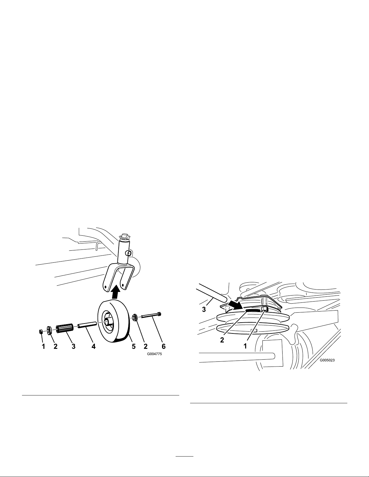
1.Removethelocknutandwheelboltholdingthe
casterwheeltothecasterfork(
Figure45).
4.Inspecttherollerbearing,bushings,spannerbushing
andinsideofthewheelhubforwear.Replaceany
defectiveorwornparts(
Figure45).
5.Toassemble,placeonebushingintothewheelhub.
Greasetherollerbearingandspannerbushingand
slidethemintothewheelhub.Placethesecond
bushingintothewheelhub(
Figure45).
6.Installthecasterwheelintothecasterforkand
securewiththewheelboltandlocknut.Tightenthe
locknutuntilthespannerbushingbottomsagainst
theinsideofthecasterforks(
Figure45).
7.Greasethettingonthecasterwheel.
AdjustingtheElectricClutch
ServiceInterval:Every100hours
Theclutchisadjustabletoensureproperengagement
andproperbraking.
1.Inserta0.015–0.021inch(0.381–0.533mm)feeler
gaugethroughoneinspectionslotinthesideofthe
assembly.Makesureitisbetweenthearmatureand
therotorfrictionsurfaces.
2.Tightenthelocknutsuntilthereisslightbindingon
thefeelergaugebutitcanbemovedeasilywithinthe
airgap(
Figure46).
Figure45
1.Locknut
2.WheelBolt5.RollerBearing
3.Bushing
4.SpannerBushing
2.Removeonebushing,thenpullthespannerbushing
androllerbearingoutofthewheelhub(Figure45).
3.Repeatthisfortheremainingslots.
4.Checkeachslotagainandmakeslightadjustments
untilthefeelergaugebetweentherotorandarmature
withveryslightcontactbetweenthem.
Figure46
1.Adjustingnut3.Feelergauge
2.Slot
3.Removetheotherbushingfromthewheelhub
andcleananygreaseanddirtfromthewheelhub
(Figure45).
35
Page 36

CoolingSystem
BrakeMaintenance
Maintenance
CleaningtheAirIntakeScreen
ServiceInterval:Beforeeachuseordaily
Beforeeachuseremoveanybuild-upofgrass,dirt
orotherdebrisfromthecylinderandcylinderhead
coolingns,airintakescreenonywheelend,and
carburetor-governorleversandlinkage.Thiswillhelp
insureadequatecoolingandcorrectenginespeedand
willreducethepossibilityofoverheatingandmechanical
damagetotheengine.
ServicingtheBrake
Beforeeachuse,checkbrakesonbothalevelsurface
andslope.
Alwayssettheparkingbrakewhenyoustopthemachine
orleaveitunattended.Iftheparkingbrakedoesnot
holdsecurely,anadjustmentisrequired.
CheckingtheParkingBrake
ServiceInterval:Beforeeachuseordaily
1.Parkthemachineonalevelsurface,disengagethe
PTO.
2.Stoptheengine,removethekey,andwaitforall
movingpartstostopbeforeleavingtheoperating
position.
3.Applytheparkingbrake.Settingtheparkingbrake
shouldtakeareasonableamountofforce.Ifthe
parkingbrakedoesnotholdsecurely,anadjustment
isrequired.RefertoAdjustingtheParkingBrake.
Note:Whenthebrakeisengaged,thebrakehandle
shouldbeinthe1o’clockposition(
Figure47).
AdjustingtheBrakes
Iftheparkingbrakedoesnotholdsecurely,an
adjustmentisrequired.
1.Parkthemachineonalevelsurface,disengagethe
PTO,andsettheparkingbrake.
2.Stoptheengine,removethekey,andwaitforall
movingpartstostopbeforeleavingtheoperating
position.
3.Checkthebrakebeforeyouadjustit;referto
CheckingtheBrakes.
4.Releasetheparkingbrake;refertoReleasingthe
ParkingBrakeinOperation(page13).
5.Loosenthetopandbottomjamnuts(
6.Toadjustthebrake,removethehairpincotterand
clevispinfromthelowerbrakelever(
7.Rotatethebrakerodintheyokes.T otightenthe
brake,lengthentherodbetweentheyokes.To
loosenthebrake,shortentherodbetweentheyokes
(Figure47).
Figure47).
Figure47).
Note:Thebrakerodshouldbethreadedintoboth
yokesthesamedistance.
8.Securetheyoketolowerbrakeleverwiththehairpin
cotterandclevispin(Figure47).
36
Page 37
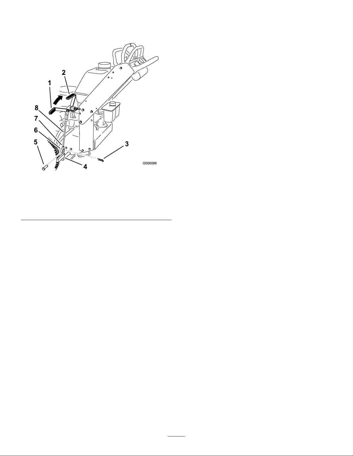
9.Tightenthetopandbottomjamnuts(Figure47).
10.Checkthebrakeoperationagain;refertoChecking
theBrake.
Figure47
1.Parkingbrakelever
(releasedposition)
2.1o’clockposition6.Yoke
3.Haripincotter7.JamNut
4.Lowerbrakelever8.Brakerod
5.Clevispin
BeltMaintenance
ReplacingtheMowerBelt
ServiceInterval:Every50hours
Squealingwhenthebeltisrotating,bladesslippingwhen
cuttinggrass,frayedbeltedges,burnmarksandcracks
aresignsofaworndeckbelt.Replacethedeckbeltif
anyoftheseconditionsareevident.
1.DisengagethePTOandsettheparkingbrake.
2.Stoptheengine,removethekey,andwaitforall
movingpartstostopbeforeleavingtheoperating
position.
3.Unlatchandremovethecarrierframecover.
4.Unlatchandremovethebeltcovers.
5.RemovethePTOdrivebelt.RefertoReplacingthe
PTODriveBelt.
6.Disconnecttheidlerarmspringtorelievetensionon
theidlerarmandidlerpulley,thenremovetheworn
mowerbelt(
7.Installthenewmowerbeltaroundthetwooutside
spindlepulleys,theidlerpulley,andinthelower
grooveofthedoublespindlepulley(
Figure49).
Figure48orFigure49).
Figure48or
8.Connecttheidlerarmspring(Figure48orFigure49).
9.InstallthePTOdrivebelt.RefertoReplacingthe
PTODriveBelt.
10.Adjustthebeltguidean1/8inch(3mm)fromthe
Figure48orFigure49).
belt(
11.Installthebeltcoversontothecuttingunitand
securethelatches.
12.Installthecarrierframecoverontothecuttingunit
andsecurethelatches.
37
Page 38
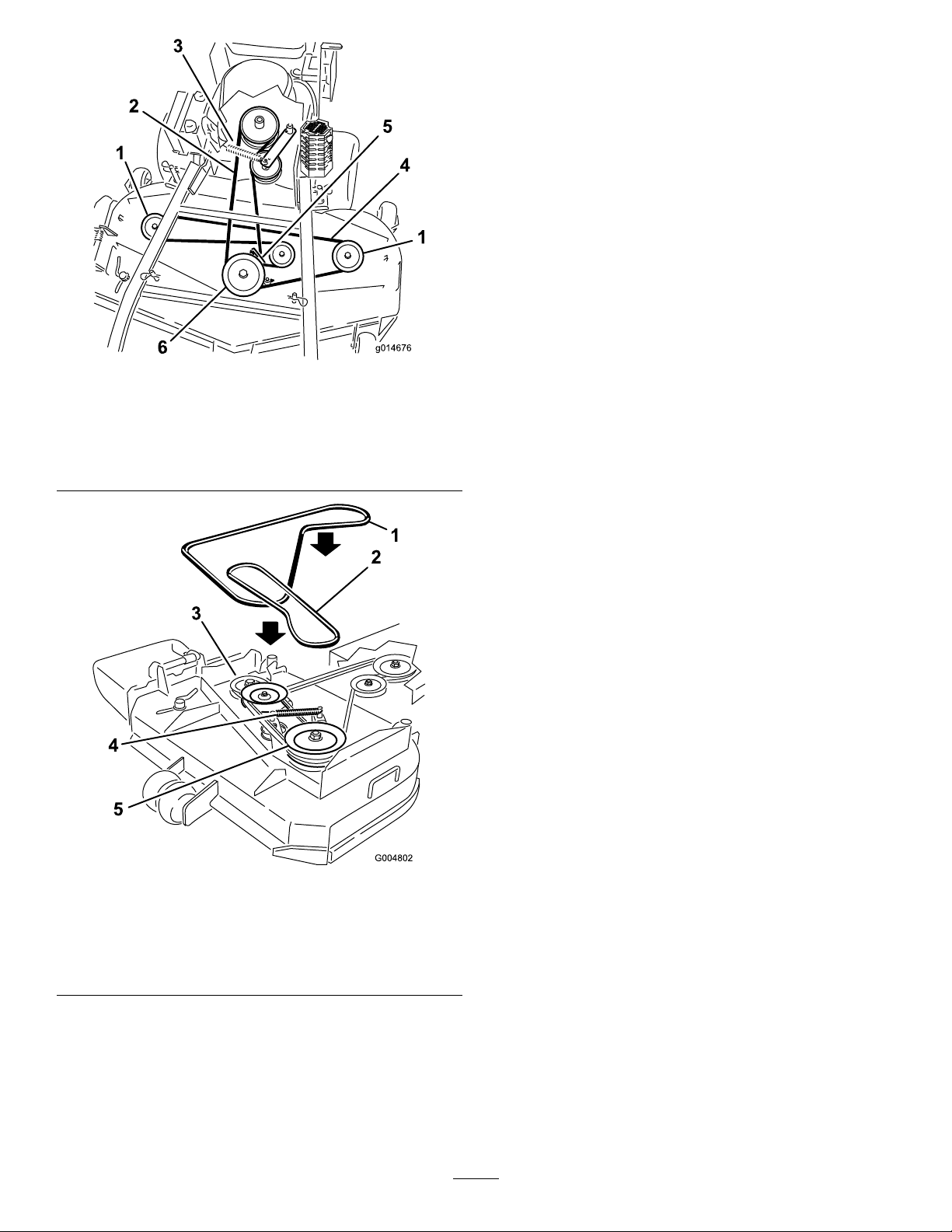
g014676
Figure48
40inch,48inch,and52inchMowerDeckshown
1.Outsidepulley
2.PTODriveBelt
3.Idlerarmspring
4.Mowerdeckbelt
5.Beltguide
6.Centerspindlepulley
aresignsofaworndrivebelt.Replacethedrivebeltif
anyoftheseconditionsareevident.
1.DisengagethePTOandsettheparkingbrake.
2.Stoptheengine,removethekey,andwaitforall
movingpartstostopbeforeleavingtheoperating
position.
3.Unlatchandremovethecarrierframecover.
4.Unlatchandremovethebeltcovers.
5.Removetheheatshieldfromtheenginedeckand
carrierframe.
6.Rollthebeltoffofthecenterpulleyonthemower
Figure50).RefertoFigure51torollthebelt
deck(
offleftpulleyfora36inchmowerdeck.Usecaution
whenremovingthebeltastensionwillincrease
becauseofthespringloadedidlerpulley .
7.Removethebeltfromtheenginepulleyandthe
springloadedidlerpulley(
Figure50).Referto
Figure51toremovethebeltfromthe36inchmower
deckpulleys.
Figure49
36inchMowerDeckshown
1.Mowerdeckbelt4.Idlerarmspring
2.PTODriveBelt
3.Drivebeltpulley
5.Drivebeltpulley
8.Installthenewbeltontotheenginepulleyandspring
loadedidlerpulley(
Figure50).
9.Rollthebeltontothecenterpulleyonthemower
deck(Figure50).Usecautionwheninstallthebelt
astensionwillincreasebecauseofthespringloaded
idlerpulley.RefertoFigure51torollthenewbelt
ontotheleftpulleyfora36inchmowerdeck.
10.Installtheheatshieldtotheenginedeckandcarrier
frame.
11.Adjustthebeltguidean1/8inch(3mm)fromthe
beltfor40,48and52inchmowerdecks(
Figure50).
12.Installthebeltcoversontothecuttingunitand
securethelatches.
13.Installthecarrierframecoverontothecarrierframe
andsecurethelatches.
ReplacingthePTODriveBelt
ServiceInterval:Every50hours
Squealingwhenthebeltisrotating,bladesslippingwhen
cuttinggrass,frayedbeltedges,burnmarksandcracks
38
Page 39
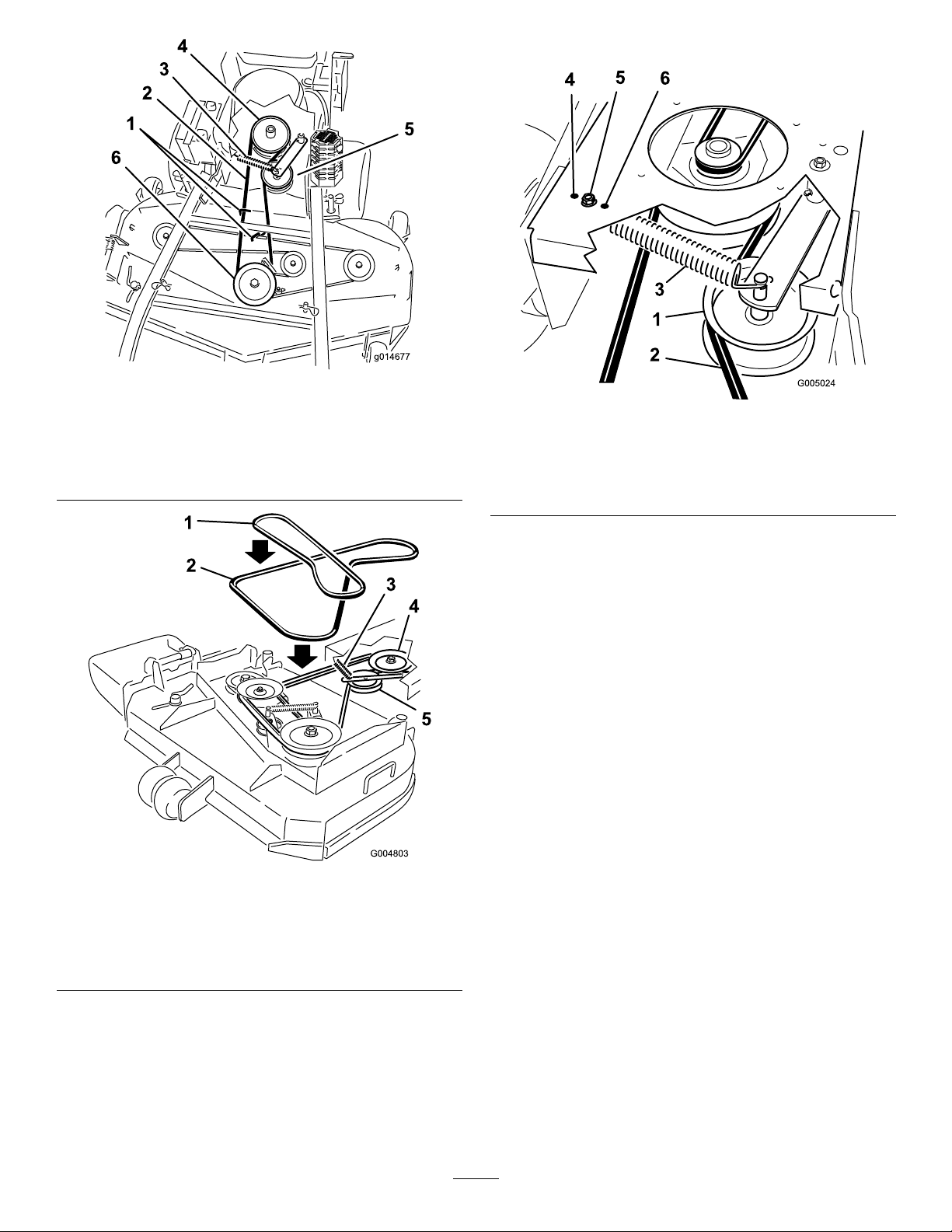
g014677
Figure50
40inch,48inch,and52inchMowerDeckshown
1.PTOdrivebeltguide4.PTOengagementpulley
2.PTOdriveBelt5.PTOdrivebeltidlerpulley
3.Idlerspring
6.Centerspindlepulley
UseFigure52fortheidlerpositionoptions.
Figure52
1.PTOdrivebeltidlerpulley4.Mosttensionforwornbelts
2.PTOdriveBelt5.Mediumtensionfornormal
3.Idlerspring
beltconditions
6.Leasttensionfornewbelts
1.Mowerdeckbelt
2.PTODriveBelt
3.Idlerarmandspring
Figure51
36inchMowerDeckshown
4.Clutchpulley
5.Idlerpulley
ReplacingthePumpDriveBelt
ServiceInterval:Every50hours
1.DisengagethePTOandsettheparkingbrake.
2.Stoptheengine,removethekey,andwaitforall
movingpartstostopbeforeleavingtheoperating
position.
3.RemovePTOdrivebelt.RefertoReplacingthe
PTODriveBeltinthe
4.Raisethemachineandsupportitwithjackstands.
5.Disconnecttheclutchwireconnectorfromthewire
harness.
6.Disconnecttheclutchretainerfromtheenginedeck
Figure53).
(
BeltMaintenance(page37).
AdjustingthePTODriveBelt
IdlerSpringAnchor
ThepositionofthePTOidlercanbeadjustedto
increaseordecreasebelttension.
39
Page 40
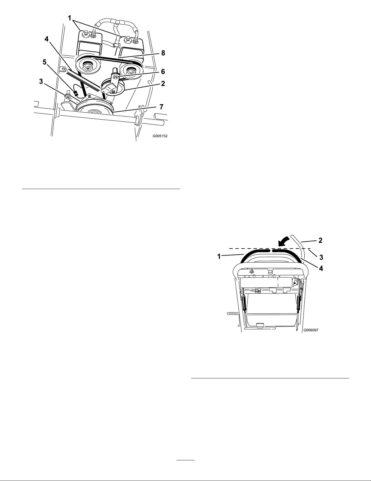
Figure53
1.Hydraulicpumps
2.Idlerpulley6.Pivotbolt
3.Clutchretainer
4.Tensionspring8.Pumpdrivebelt
5.Clutchwireconnector
7.Drivepulley
7.Unhooktheidlerspringfromtheframe(Figure53).
8.Installthenewbeltaroundclutchandthetwodrive
pulleys.
9.Installtheidlerspringbetweenidlerarmandframe
bracket(
Figure53).
ControlsSystem
Maintenance
AdjustingtheMotionControl
HandlePositions
AdjustingtheRightSideMotionControl
Lever
Ifthemotioncontrolleversdonotalignhorizontally,
adjusttherightsidemotioncontrollever.
Note:Adjustthehorizontalalignmentbeforethefront
tobackalignment.
1.DisengagethePTO,movetherightsidemotion
controllevertotheneutralpositionandsetthe
parkingbrake.
2.Stoptheengine,removethekey,andwaitforall
movingpartstostopbeforeleavingtheoperating
position.
3.Pushtherightmotioncontrolleverdownoutof
lockedneutralposition(
4.Checkifitalignshorizontallywiththeleftmotion
controllever(
Figure54).
Figure54).
10.Installtheclutchretainertotheenginedeck
(Figure53).
11.Connecttheclutchwireconnectortothewire
harness.
12.InstallthePTOdrivebelt.
Figure54
1.Leftmotioncontrollever3.Checkthehorizontal
2.Rightmotioncontrollever
inneutrallockedposition
alignmenthere
4.Rightmotioncontrollever
5.Toadjusttherightmotioncontrolleverhorizontally,
thecamneedstobeadjusted.
6.Removethecoverunderthecontrolpanel.
7.Loosenthenutandboltholdingthecam(
Figure55).
8.Adjustthecamuntilitalignswiththeleftmotion
controlleverandtightenthenutandboltforthe
cam.
40
Page 41
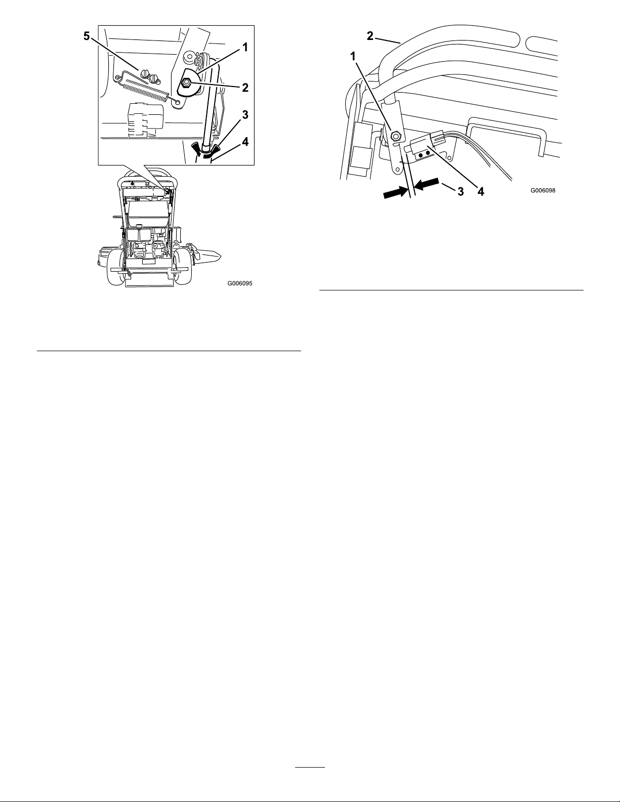
Figure55
1.Cam
2.Nutandbolt
3.Wingnut
4.Turnbuckle
5.Switchscrews
9.Afterthecamisadjusted,theleverswitchneedsto
bechecked.
10.Checkthegapbetweenthecontrolleverandswitch
asshownin
Figure56.Thegapneedstobebetween
a1/16inchto3/32inch(1.6mmto2.4mm).
11.Ifneeded,loosenthescrewsholdingtheswitchand
adjusttheswitch.
12.Tightenthescrewsandinstallthecoverunderthe
controlpanel.
Figure56
1.Rightsidemotioncontrol
leverpivotshownunder
controls
2.Rightsidemotioncontrol
lever
3.1/16inchto3/32inch
(1.6mmto2.4mm)gap
neededbetweenswitch
andcontrollever
4.Switch
AdjustingtheNeutralPostionforthe
MotionControlLevers
Important:Ensurethetrackingofthemoweris
correctafteradjustingthemotioncontrollevers.
Afteradjustingthetracking,themotioncontrol
leversmaynotaligntheexactlyfronttoback
Figure57).
(
Ifthemotioncontrolleversdonotalignfronttoback,
ortherightsidecontrolleverdoesnotmoveeasilyinto
theneutrallockposition,adjustmentisrequired.Adjust
eachleverandcontrolrodseparately.
Note:Adjustthehorizontalalignmentbeforethefront
tobackalignment.
1.Afterthehorizontalalignmentisnished,checkthe
fronttobackalignment(
41
Figure57).
Page 42
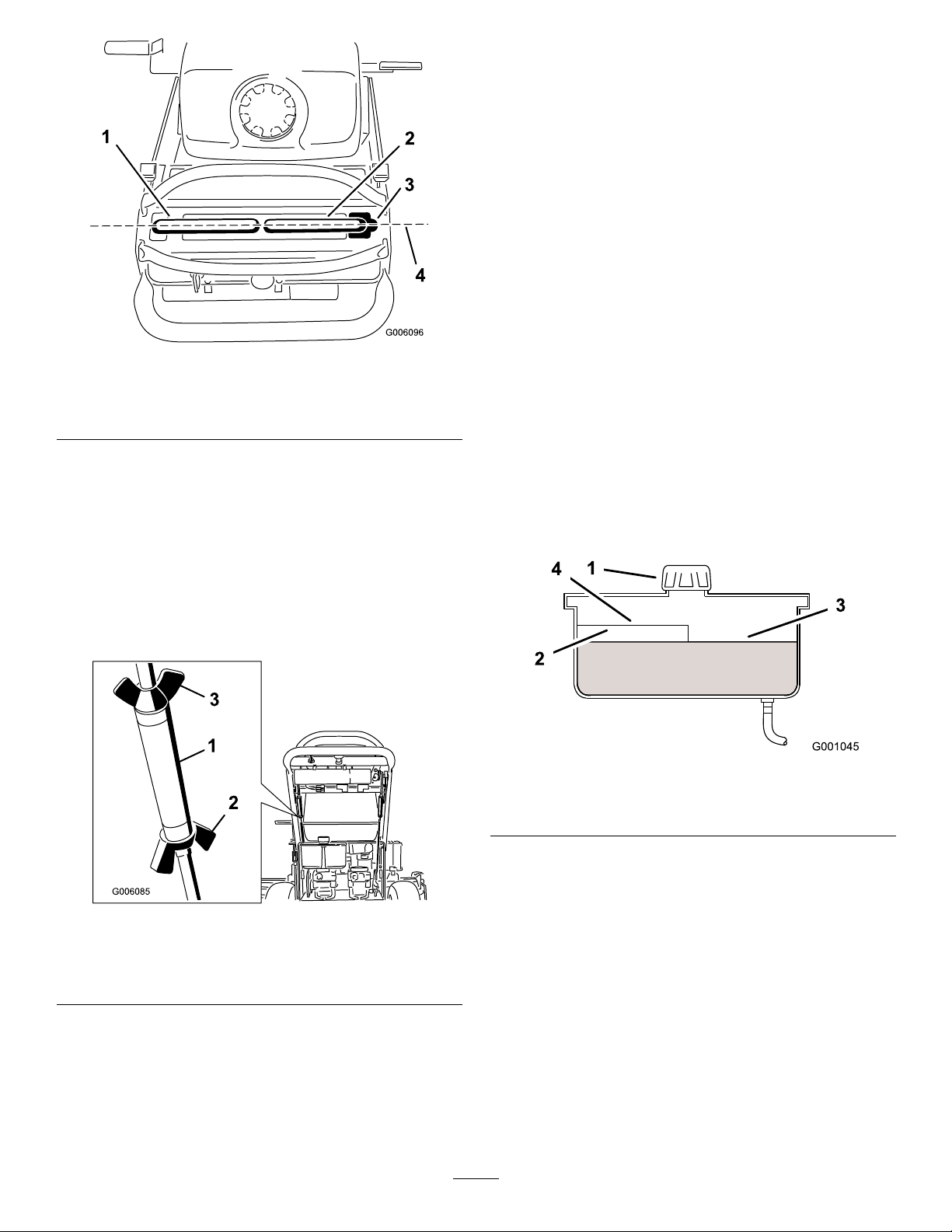
Figure57
1.Leftmotioncontrollever
2.Rightmotioncontrollever4.Alignthecontrollevers
3.Neutrallockedposition
fronttobackhere
2.Loosenthewingnutsontherightcontrolrodand
rotatetheturnbuckleinorouttoensuretheright
sidecontrolleveriscenteredintheneutrallock
position.Securetheturnbuckleinpositionwiththe
wingnuts(Figure58).
HydraulicSystem
Maintenance
ServicingtheHydraulic
System
CheckingtheHydraulicFluid
ServiceInterval:Aftertherst8hours
Every25hours
Note:Therearetwowaysofcheckingthehydraulicoil.
Oneiswhentheoiliswarmandoneiswhentheoilis
cold.Thebafeinsidethetankhastwolevelsdepending
iftheoiliswarmorcold.
1.Positionmachineonalevelsurface.
2.Disengagethepowertakeoff(PTO)andshutoff
theengine.
3.Waitforallmovingpartstostopbeforeleavingthe
operatingpositionandthensettheparkingbrake.
4.Cleanareaaroundcapandllerneckofhydraulic
Figure59).
tank(
3.Loosenthewingnutsontheleftcontrolrodand
rotatetheturnbuckleinorouttochangethetracking.
Securetheturnbuckleinpositionwiththewingnuts
Figure58).
(
Figure58
1.Turnbuckle
2.Bottomwingnut
3.Topwingnut(lefthand
threaded)
4.Checkforpropertracking.Adjusttheleftcontrol
rodifachangeisneeded.RefertoAdjustingthe
TrackingintheOperationSection.
Figure59
1.Cap3.Colduidlevel-full
2.Bafe4.Hotuidlevel-full
5.Removecapfromllerneck.Lookinsidetocheck
theuidlevelinthereservoir.(Figure59).
6.Adduidtothereservoiruntilitreachesthecold
levelofthebafe.
7.Runthemachineatlowidlefor15minutestoallow
anyairtopurgeoutofthesystemandwarmuid.
RefertoStartingandStoppingtheEngine.
8.Rechecktheuidlevelwhiletheuidiswarm.If
required,adduidtothereservoiruntilitreaches
thehotlevelofthebafe.
Note:Theuidlevelshouldbetothetopofthehot
levelofthebafe,whentheuidiswarm(
Figure59).
9.Installcaponllerneck.
42
Page 43
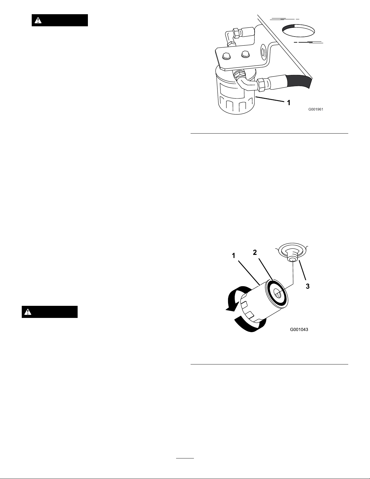
WARNING
Hydraulicuidescapingunderpressurecan
penetrateskinandcauseinjury.
•Ifhydraulicuidisinjectedintotheskin
itmustbesurgicallyremovedwithinafew
hoursbyadoctorfamiliarwiththistypeof
injury.Gangrenemayresultifthisisnot
done.
•Keepbodyandhandsawayfrompinhole
leaksornozzlesthatejecthighpressure
hydraulicuid.
•Usecardboardorpapertondhydraulic
leaks.
Figure60
•Safelyrelieveallpressureinthehydraulic
systembeforeperforminganyworkonthe
hydraulicsystem.
•Makesureallhydraulicuidhosesand
linesareingoodconditionandallhydraulic
connectionsandttingsaretightbefore
applyingpressuretohydraulicsystem.
ReplacingtheHydraulicFilterand
HydraulicOil
ServiceInterval:Aftertherst8hours
Every250hours—Changethe
hydrauliclterandhydraulicoilwhen
usingMobil
®
1oil.
Every500hours—Changethe
hydrauliclterandhydraulicoil
whenusingToro
®
hydraulicoil.
WARNING
4.Removetheoldlter,allowtheoiltodrainandwipe
thelteradaptergasketsurfaceclean(Figure61).
5.Applyathincoathydraulicuidtotherubbergasket
onthereplacementlter.
6.Installreplacementhydrauliclterontothelter
adapter.Donottighten.
7.Fillthehydraulictankwithhydraulicuiduntilthe
uidoverowsthelterandthenturntheoillter
clockwiseuntiltherubbergasketcontactsthelter
adapter,thentightenthelteranadditional1/2turn
Figure61).
(
HYPR-OIL
™
500
Hothydraulicuidcancausesevereburns.
Allowthehydraulicuidtocoolbeforeperforming
anymaintenancetothehydraulicsystem.
1.DisengagethePTOandsettheparkingbrake.
2.Stoptheengineandwaitforallmovingpartstostop
beforeleavingtheoperatingposition.
Important:Donotsubstituteautomotiveoil
lterorseverehydraulicsystemdamagemay
result.
3.Locatethelterunderthefueltankandplacedrain
panunderlter(Figure60).
Figure61
1.Hydrauliclter
2.Gasket
3.Adapter
8.Cleanupanyspilleduid.
9.Checktheuidinthereservoir,adduidtothetank
untilitreachesthecoldbafeofthetank.
Important:Useoilspecied.Otheruids
couldcausesystemdamage.
10.Startengineandletrunforabouttwominutesto
purgeairfromthesystem.Stoptheengineand
43
Page 44

checkforleaks.Ifoneorbothwheelswillnotdrive,
refertoBleedingHydraulicSystem.
11.Rechecklevelandadduid,ifrequired.Donot
overll.
BleedingtheHydraulicSystem
Thetractionsystemisselfbleeding,however,itmaybe
necessarytobleedthesystemifuidischangedorafter
workisperformedonthesystem.
1.DisengagethePTOandsettheparkingbrake.
2.Stoptheengineandwaitforallmovingpartstostop
beforeleavingtheoperatingposition.
3.Raisetherearofthemachineupontojackstands
highenoughtoraisethedrivewheelsofftheground.
4.Starttheengineandmovethethrottlecontroltoidle
position.
Ifthedrivewheeldoesnotrotate,itispossibleto
assistthepurgingofthesystembycarefullyrotating
thetireintheforwarddirection.
WARNING
Hydraulicuidescapingunderpressurecan
penetrateskinandcauseinjury.
•Ifhydraulicuidisinjectedintotheskinit
mustbesurgicallyremovedwithinafewhours
byadoctorfamiliarwiththistypeofinjury.
Gangrenemayresultifthisisnotdone.
•Keepbodyandhandsawayfrompinholeleaks
ornozzlesthatejecthighpressurehydraulic
uid.
•Usecardboardorpapertondhydraulicleaks.
•Safelyrelieveallpressureinthehydraulicsystem
beforeperforminganyworkonthehydraulic
system.
•Makesureallhydraulicuidhosesandlinesare
ingoodconditionandallhydraulicconnections
andttingsaretightbeforeapplyingpressureto
hydraulicsystem.
5.Checkthehydraulicuidlevelasitdropsadduid
asrequiredtomaintaintheproperlevel.
6.Repeatthisprocedurefortheoppositewheel.
7.Thoroughlycleantheareaaroundeachofthecharge
pumphousings.
CheckingtheHydraulicLines
ServiceInterval:Every100hours
Checkhydrauliclinesandhosesforleaks,loosettings,
kinkedlines,loosemountingsupports,wear,weather
andchemicaldeterioration.Makenecessaryrepairs
beforeoperating.
Note:Keepareasaroundhydraulicsystemcleanfrom
grassanddebrisbuildup.
44
Page 45
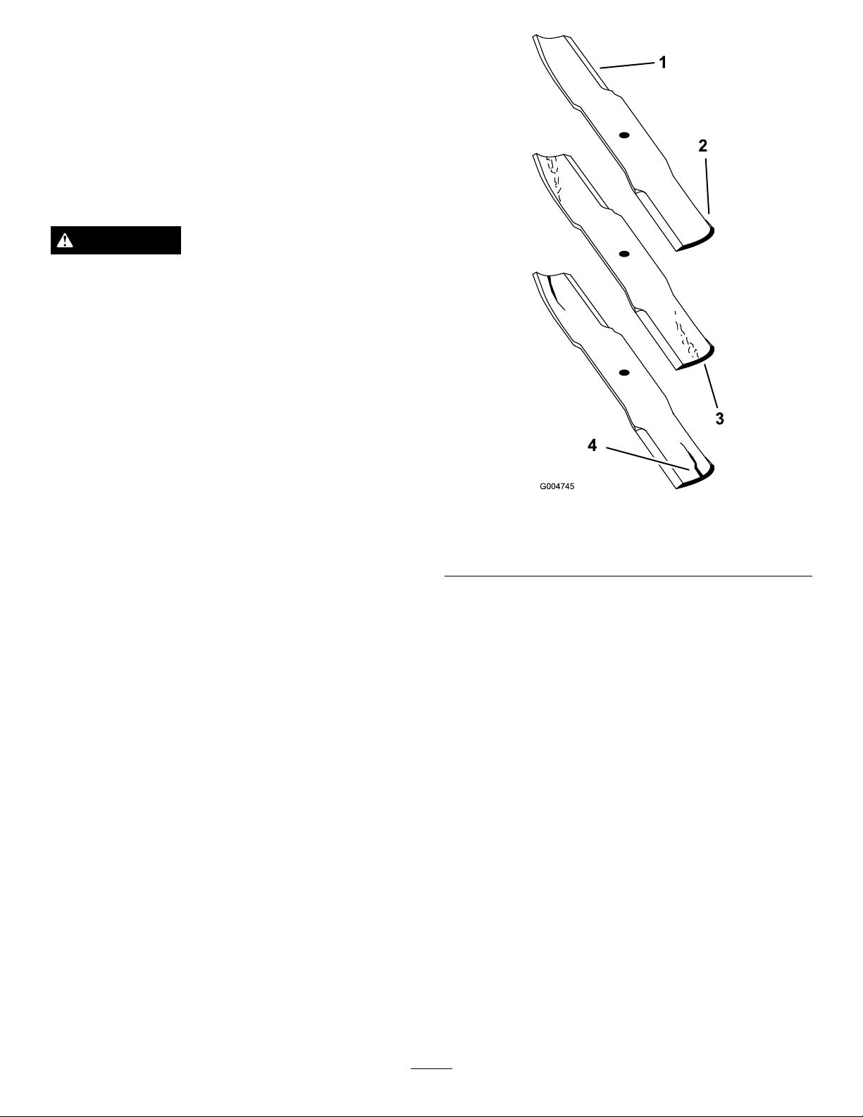
MowerDeck
Maintenance
ServicingtheCuttingBlades
Toensureasuperiorqualityofcut,keeptheblades
sharp.Forconvenientsharpeningandreplacement,you
maywanttokeepextrabladesonhand.
WARNING
Awornordamagedbladecanbreak,andapiece
ofthebladecouldbethrownintotheoperator’s
orbystander’sarea,resultinginseriouspersonal
injuryordeath.
•Inspectthebladesperiodicallyforwearor
damage.
•Replaceawornordamagedblade.
BeforeInspectingorServicingthe
Blades
Parkthemachineonalevelsurface,disengagetheblades
andsettheparkingbrake.Turntheignitionkeytooff.
Removethekeyanddisconnectthesparkplugwires
fromthesparkplugs.
InspectingtheBlades
ServiceInterval:Beforeeachuseordaily
1.Inspectthecuttingedges(Figure62).Iftheedges
arenotsharporhavenicks,removeandsharpenthe
blades.RefertoSharpeningtheBlades.
Figure62
1.CuttingEdge3.Wear/slotformingin
curvedarea
2.Sail4.Crackinthecurvedarea
2.Inspecttheblades,especiallythecurvedarea
(Figure62).Ifyounoticeanycracks,wear,ora
slotforminginthisarea(item3inFigure62),
immediatelyinstallanewblade.
CheckingforBentBlades
1.DisengagethePTO,movethemotioncontrollevers
totheneutrallockedpositionandsettheparking
brake.
2.Stoptheengine,removethekey,andwaitforall
movingpartstostopbeforeleavingtheoperating
position.
3.Rotatethebladesuntiltheendsfaceforwardand
backward.Measurefromalevelsurfacetothe
cuttingedge,positionA,oftheblades(Figure63
).Notethisdimension.For36inchmowerdecks
useFigure64.
45
Page 46
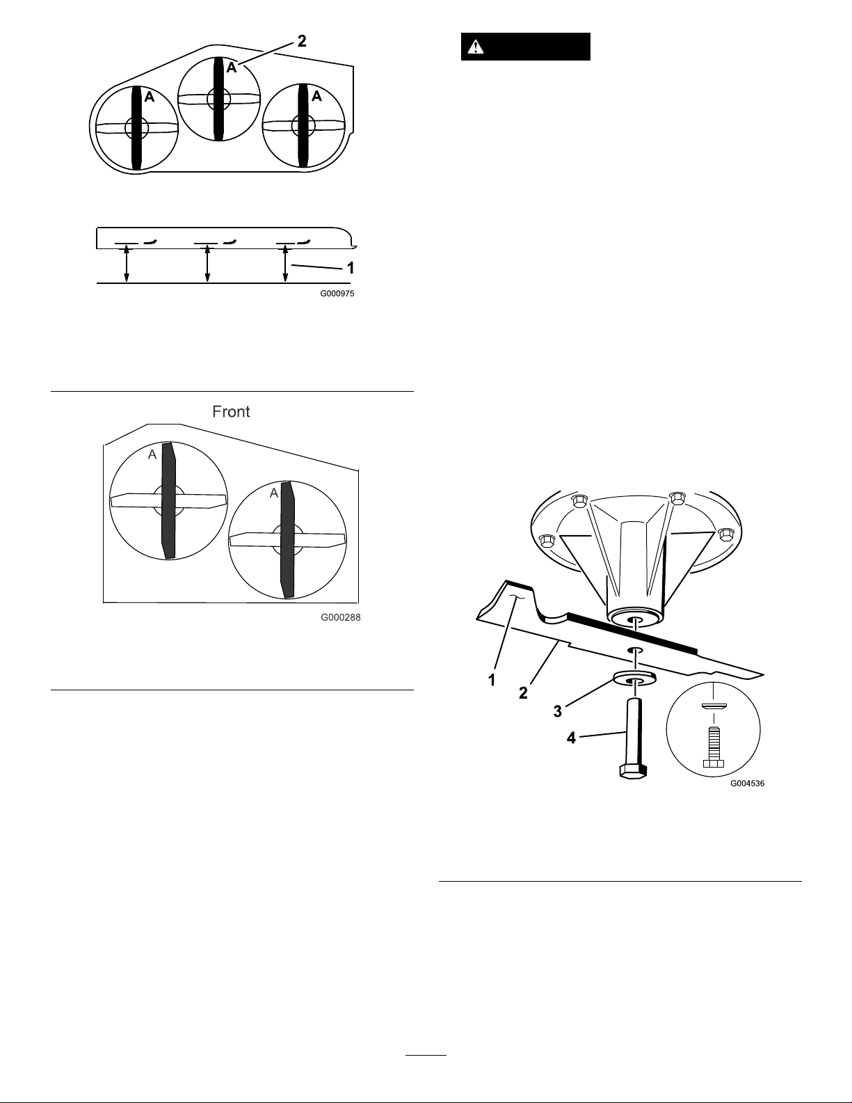
Figure63
40inch,48inch,and52inchMowerDeckshown
1.Measureherefromblade
tohardsurface
2.PositionA
WARNING
Abladethatisbentordamagedcouldbreak
apartandcouldseriouslyinjureorkillyouor
bystanders.
•Alwaysreplacebentordamagedbladewith
anewblade.
•Neverleorcreatesharpnotchesinthe
edgesorsurfacesofblade.
RemovingtheBlades
Bladesmustbereplacedifasolidobjectishit,ifthe
bladeisoutofbalanceorisbent.T oensureoptimum
performanceandcontinuedsafetyconformanceof
themachine,usegenuineT ororeplacementblades.
Replacementbladesmadebyothermanufacturersmay
resultinnon-conformancewithsafetystandards.
1.Holdthebladeendusingaragorthickly-padded
glove.
2.For40and48inchmowerdecks,removetheblade
bolt,curvedwasher,andbladefromthespindle
Figure65).
shaft(
Figure64
36inchMowerDeckshown
4.Rotatetheoppositeendsofthebladesforward.
5.Measurefromalevelsurfacetothecuttingedgeof
thebladesatthesamepositionasinstep3above.
Thedifferencebetweenthedimensionsobtainedin
steps3and4mustnotexceed1/8inch(3mm).If
thisdimensionexceeds1/8inch(3mm),theblade
isbentandmustbereplaced;refertoRemovingthe
BladesandInstallingtheBlades.
Figure65
40inchand48inchMowerDecks
1.SailAreaofBlade3.Curvedwasher
2.Blade4.BladeBolt
3.For36and52inchmowerdecks,removetheblade
bolt,curvedwasher,bladestiffener,andbladefrom
thespindleshaft(Figure66).
46
Page 47
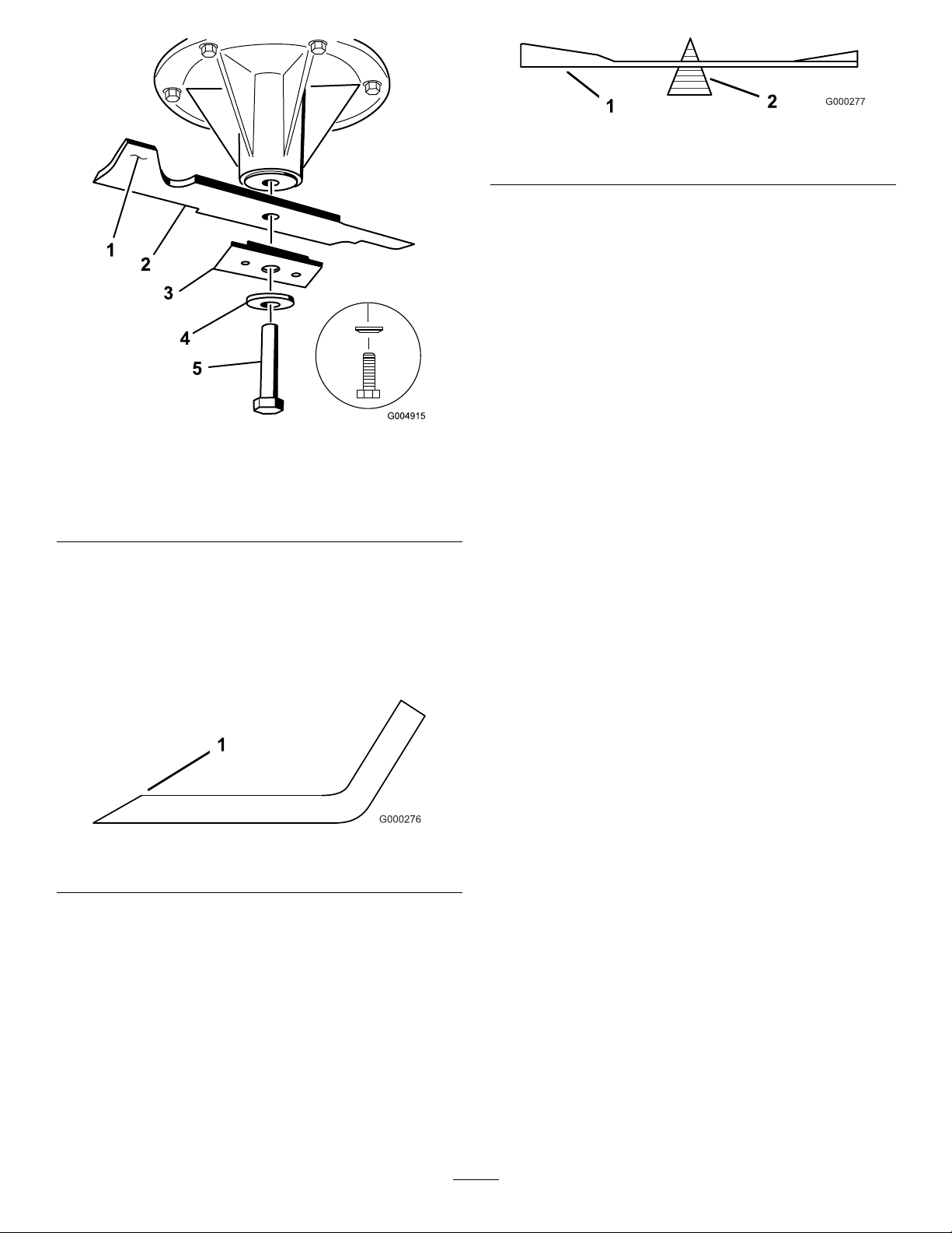
Figure66
36inchand52inchMowerDecks
Figure68
1.Blade2.Balancer
InstallingtheBlades
1.Installthebladeontothespindleshaft(Figure65).
Important:Thesailpartoftheblademustbe
pointingupward,towardtheinsideofthemower
toensurepropercutting(Figure65).
2.For40inchand48inchmowerdecks,installthe
blade,curvedwasher,andbladebolt(Figure65).
3.For36inchand52inchmowerdecks,installthe
blade,stiffener,curvedwasher,andbladebolt
Figure66).
(
1.SailAreaofBlade4.Curvedwasher
2.Blade5.BladeBolt
3.Bladestiffener
SharpeningtheBlades
1.Usealetosharpenthecuttingedgeatbothends
oftheblade(Figure67).Maintaintheoriginalangle.
Thebladeretainsitsbalanceifthesameamountof
materialisremovedfrombothcuttingedges.
Figure67
1.Sharpenatoriginalangle
2.Checkthebalanceofthebladebyputtingitona
bladebalancer(Figure68).Ifthebladestaysina
horizontalposition,thebladeisbalancedandcanbe
used.Ifthebladeisnotbalanced,lesomemetaloff
theendofthesailareaonly(Figure65).Repeatthis
procedureuntilthebladeisbalanced.
4.Torquethebladeboltto85-110ft-lb(115-140N-m).
CorrectingtheMowerQuality
ofCut
Ifonedeckbladecutslowerthantheother,correctas
follows.
Note:Tireairpressureiscriticalintheseprocedures.
Makesurealltireshavecorrectpressure.
1.DisengagethePTOandsettheparkingbrake.
2.Stoptheengine,removethekey,andwaitforall
movingpartstostopbeforeleavingtheoperating
position.Disconnectthesparkplugwire(s)from
thesparkplug(s).
3.Adjustthetirepressureinthe
reartirestospecications;referto
DriveSystemMaintenance(page33).
4.Checkthatthebladesandspindleshaftsarenot
bent.RefertoCheckingforBentBlades.
5.Settheheight-of-cuttothe4inch(101.6mm)
position.RefertoAdjustingtheHeight-Of-Cutin
Operation(page13).
6.PerformthestepsinthefollowingsectionsFrame
SetUp,CheckingFront-to-RearPitch,andChecking
Side-to-SideLeveling.
47
Page 48
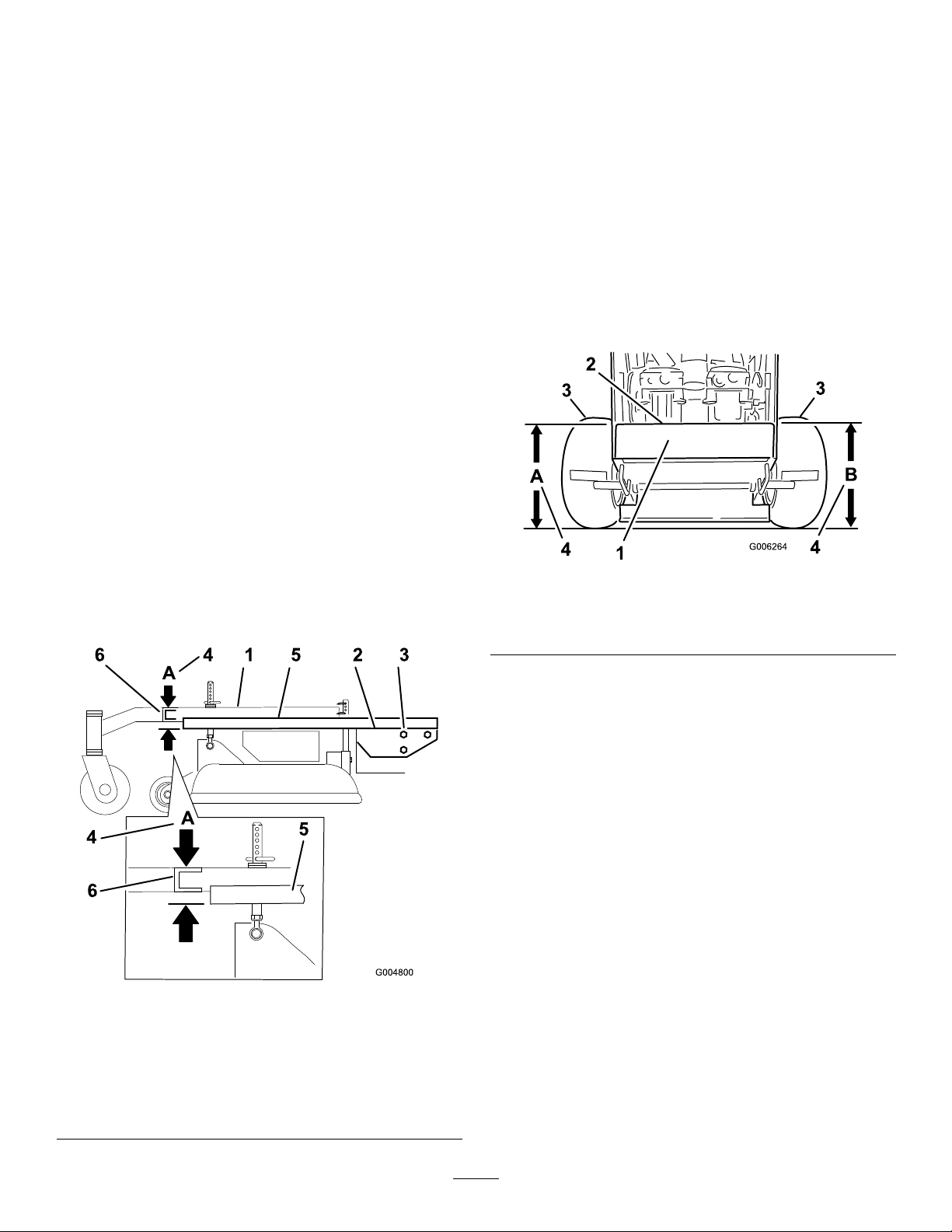
FrameSetUp
CheckingtheCarrierFrameandEngine
DeckAlignment
Note:MisalignmentcancauseexcesswearonthePTO
drivebelt.
1.DisengagethePTOandsettheparkingbrake.
2.Stoptheengine,removethekey,andwaitforall
movingpartstostopbeforeleavingtheoperating
position.
3.Placealongstraightedgeontopoftheenginedeck
asshowninFigure69.
4.Atthecarrierframecrosschannel,measurethe
heightatlocationA(Figure69).Thismeasurement
mustbe1-5/16inch(33mm),plusorminusa1/4
inch(6mm).
5.IftheheightatlocationAisnotcorrect,adjustment
isneeded.
6.Loosenthecarrierframemountingboltsonboth
sidesofthemachine(Figure69).
CheckingtheEngineDeckHeight
1.DisengagethePTOandsettheparkingbrake.
2.Stoptheengine,removethekey,andwaitforall
movingpartstostopbeforeleavingtheoperating
position.
3.Adjustthetirepressureinthe
reartirestospecications;referto
DriveSystemMaintenance(page33).
4.MeasureenginedeckheightatlocationA(Figure70).
5.MeasureenginedeckheightatlocationB(Figure70).
6.IftheheightatlocationAandBarenotthesame,
changetirepressureslightlytomakethemthesame.
7.Alignthecarrierframeandenginedecktomatch
1-5/16inch(33mm),plusorminusa1/4inch(6
mm)atlocationA(Figure69).
8.Tightenthecarrierframemountingboltsonboth
sidesofthemachine.
Figure70
1.Backviewofmachine
2.Topofenginedeck4.Sameheightatlocations
3.Tires
AandB
CheckingtheCarrierFrame
Front-to-RearPitch
Thecarrierframemusthaveapitchbetween1/8inch
(3mm)to3/8inch(9mm)overthelengthof24inches
(61cm)onthecarrierframe(Figure71).
1.Measureout24inches(61cm)onthecarrierframe
(Figure71).
Figure69
1.CarrierFrame4.LocationA,1-5/16inch
2.Topofenginedeck5.Straightedge
3.Carrierframemounting
bolts
(33mm)±1/4inch(6mm)
6.Carrierframecross
channel
48
Page 49
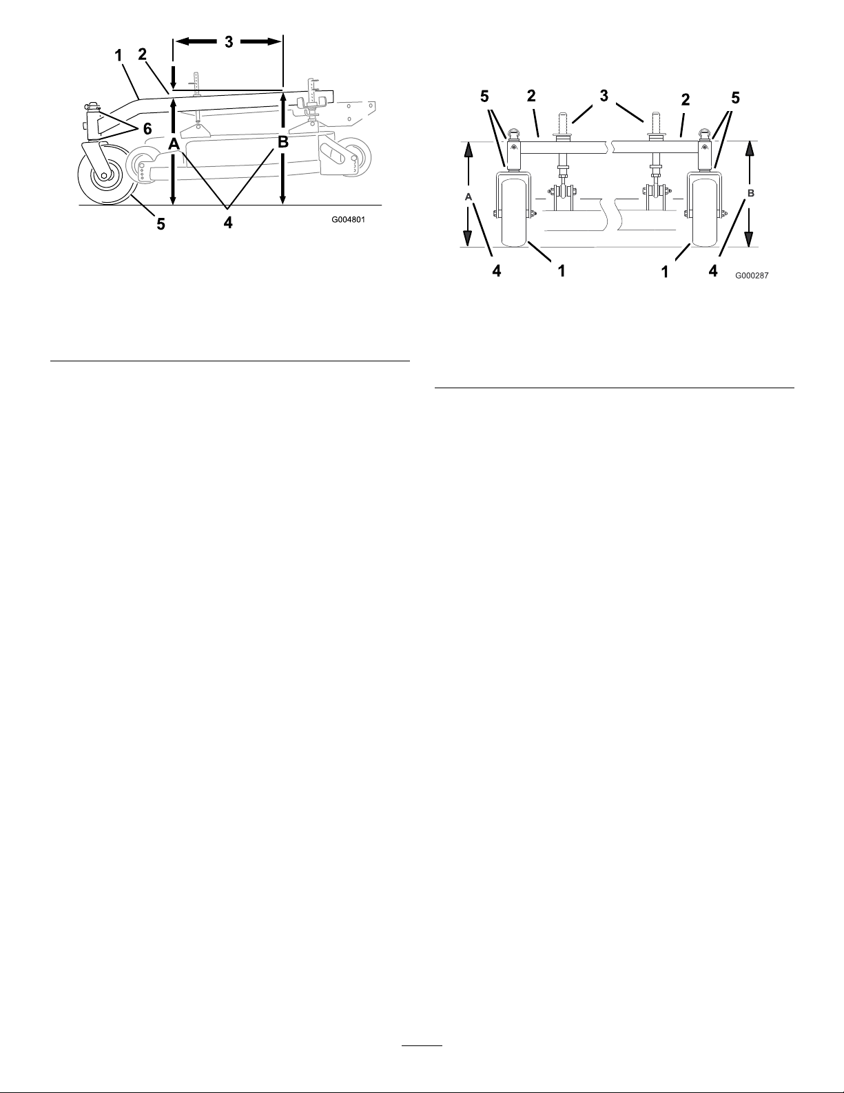
Figure71
1.CarrierFrame
2.1/8inch-3/8inch(3-10
mm)pitchover24inch(61
cm)length
3.24inches(61cm)6.Casterspacers
4.HeightatlocationsAand
B
5.CasterWheel
2.MeasurecarrierframeheightatlocationA
(Figure71).
makeitlevel.Thetirepressuremayalsobeadjusted
slightlytomakeitlevel.
Figure72
1.CasterWheel4.Sameheightatlocations
AandB
2.CarrierFrame5.Casterspacers
3.Frontheight-of-cutpins
3.MeasurecarrierframeheightatlocationB
(Figure71).
4.TheheightatlocationAmustbean1/8-3/8inch(3
mm-10mm)lowerthanlocationB(Figure71).
5.Ifthecarrierframeisnotcorrect,movecaster
spacerstomakeitan1/8-3/8inch(3-10mm)pitch
Figure71).Movespacersfromtoporbottomto
(
makethecorrectpitch.
6.Thetirepressuremayalsobeadjustedslightlyto
makean1/8-3/8inch(3-10mm)pitch.
CheckingtheCarrierFrame
Side-to-SideHeight
Thecarrierframeneedstobeparallelside-to-sidefrom
theground.
1.DisengagethePTOandsettheparkingbrake.
2.Stoptheengine,removethekey,andwaitforall
movingpartstostopbeforeleavingtheoperating
position.
CheckingtheMowerDeck
Front-to-RearPitch
1.Adjustthetirepressureinthe
reartirestospecications;referto
DriveSystemMaintenance(page33).
2.Positiononebladefront-to-rear.MeasureatAand
Blocationsfromalevelsurfacetothecuttingedge
ofthebladetips(Figure73orFigure74).For36
inchmowerdecksuseFigure74.
3.Themowerbladeshouldbea1/4inch(6mm)lower
infrontatAthanintherearatB.Rotatebladesand
repeatforotherblades.Ifitisnotcorrect,proceed
toChangingtheDeckFront-to-RearPitch.
3.Adjustthetirepressureinthe
reartirestospecications;referto
DriveSystemMaintenance(page33).
4.MeasurecarrierframeheightatlocationA
(Figure72).
5.MeasurecarrierframeheightatlocationB
(Figure72).
6.Ifthecarrierframeheightisnotthesamemove
spacersfromtoporbottomofcasterwheel,to
49
Page 50
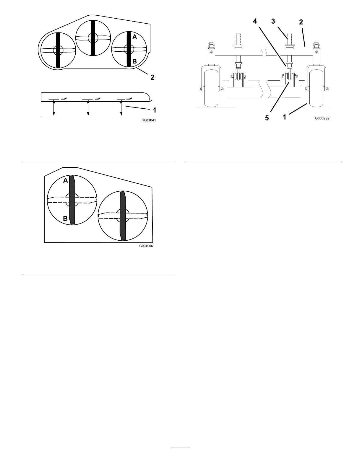
Figure73
40inch,48inch,and52inchMowerDeckshown
1.MeasurebladeatpointsA
andB
2.Measurefromalevel
Figure75
1.CasterWheel
2.CarrierFrame
surface
3.Frontheight-of-cutpins
4.Jamnut
5.Balljoint
2.Toraisethefrontofthedeck,loosenjamnutand
rotatethefrontpinclockwise(
Figure75).
3.Tolowerthefrontofthedeck,loosenjamnutand
rotatethefrontpincounterclockwise(Figure75).
4.Positionthebladesfront-to-rear.MeasureatCand
Dlocations(
Figure73)fromalevelsurfacetothe
cuttingedgeoftheblades.
5.Checktheside-to-sidelevelingofthecuttingunit.
Figure74
36inchMowerDeckshown
ChangingtheMowerDeck
Front-to-RearPitch
Changingthefront-to-rearpitchisdonebyadjustingthe
frontheight-of-cutposts.
1.Tochangethefront-to-rearpitch,thefront
height-of-cutpostscanbeadjusted(
Figure75).
6.Tightenthejamnuts(Figure75).
CheckingtheMowerDeck
Side-to-SideHeight
1.Adjustthereartirepressuretospecications;refer
toDriveSystemMaintenance(page33).
2.Positionthebladesside-to-side.MeasureatCand
Dlocationsfromalevelsurfacetothecuttingedge
ofbladetips(
useFigure77.
Figure76).For36inchmowerdecks
50
Page 51
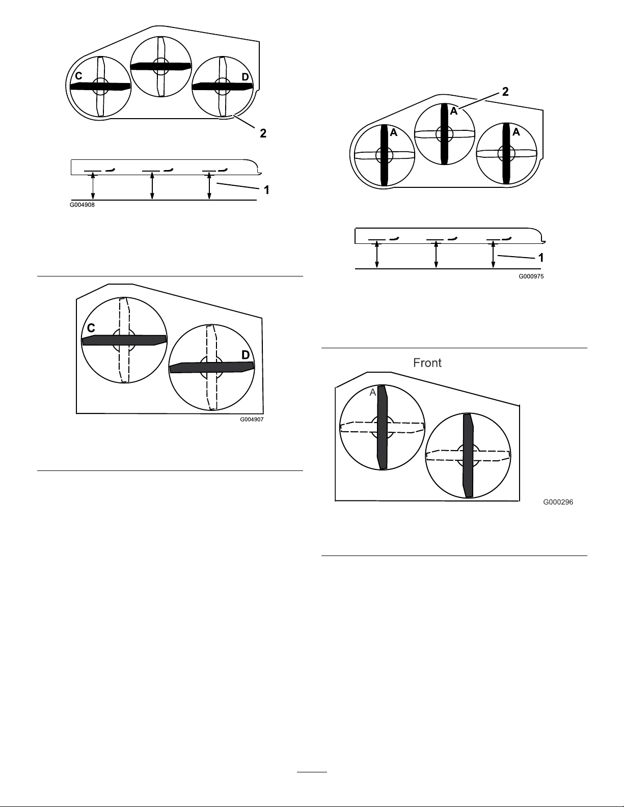
Figure76
40inch,48inch,and52inchMowerDeckshown
3.Withthemachineonlevelsurface,positiononeblade
front-to-rear.MeasureatAandfromlevelsurfaceto
thecuttingedgeofthebladetips(Figure78).For36
inchmowerdecksuse
Figure79.
1.Measurefromalevel
surface
36inchMowerDeckshown
2.MeasurebladeatpointsC
andD
Figure77
3.ThedifferencebetweenmeasurementsCandD
shouldbenomorethan1/4inch(6mm).
ChangingtheMowerDeck
Figure78
40inch,48inch,and52inchMowerDeckshown
1.Measurefromalevel
surface
36inchMowerDeckshown
2.MeasurebladeatpointA
Figure79
Side-to-SideHeight
Changingtheside-to-sideheightisdonebyadjustingthe
reartirepressureandcasterspacers.
1.Changethereartirepressure.Dothistothe
correspondingsidethatneedsadjustment.
2.Adjustthecasterspacer.
3.Recheckthefront-to-rearpitchandsidetoside
levelingofthecuttingunit.
MatchingHeightofCut
1.Checkthereartirepressure.
2.Settheheight-of-cuttothe4inch(101.6mm)
positionfollowingtheheight-of-cutdecal.
4.Themeasurementshouldbe4inch(101.6mm).
5.Ifitdoesnotmeasurecorrectly:
A.Adjustthereartirepressure.
B.Adjustthecasterforkspacers.
C.Adjustthefrontmowerdecksupportpins.
6.Checkthecarrierframefront-to-rearpitch.
51
Page 52
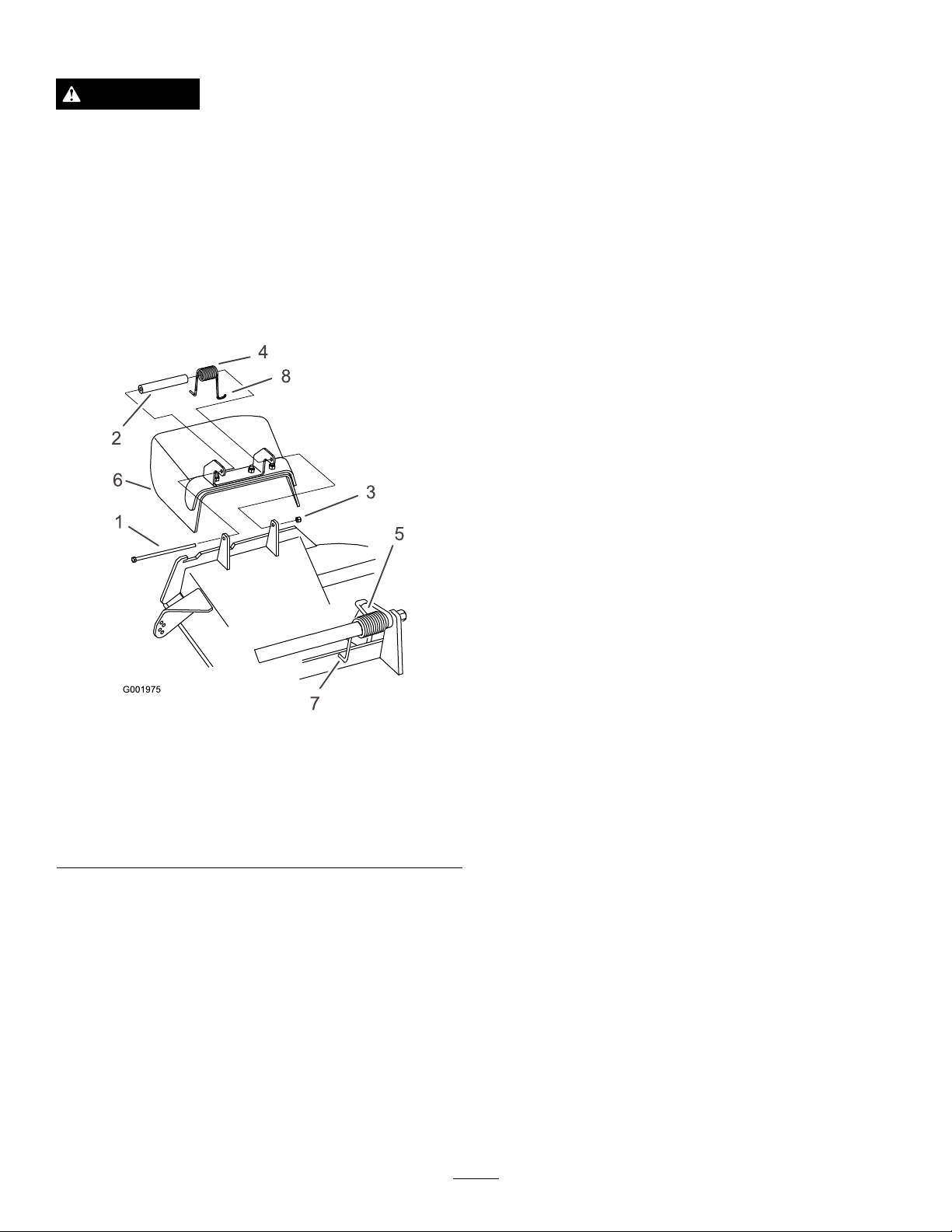
ReplacingtheGrassDeector
Cleaning
WARNING
Anuncovereddischargeopeningcouldallowthe
lawnmowertothrowobjectsintheoperator’sor
bystander’sdirectionandresultinseriousinjury.
Also,contactwiththebladecouldoccur.
Neveroperatethelawnmowerunlessyouinstalla
coverplate,amulchplate,grassdeectororbagger.
1.Removethelocknut,bolt,springandspacerholding
thedeectortothepivotbrackets(Figure80).
Removedamagedorworngrassdeector.
CleaningUndertheMower
ServiceInterval:Beforeeachuseordaily
Removethegrassbuildupunderthemowerdaily.
1.DisengagethePTO,movethemotioncontrollevers
totheneutrallockedpositionandsettheparking
brake.
2.Stoptheengine,removethekey,andwaitforall
movingpartstostopbeforeleavingtheoperating
position.
3.Raisethefrontofthemachineandusejackstandsto
supportthemower.
WasteDisposal
Engineoil,batteries,hydraulicoil,andenginecoolant
arepollutantstotheenvironment.Disposeofthese
accordingtoyourstateandlocalregulations.
Figure80
1.Bolt
2.Spacer6.GrassDeector
3.Locknut
4.Spring8.Jhookendofspring
2.Placespacerandspringontograssdeector.Place
theLendofspringbehinddeckedge.
Note:MakesuretheLendofspringisinstalled
behinddeckedgebeforeinstallingtheboltasshown
inFigure80.
3.Installboltandnut.PlacetheJhookendofspring
aroundgrassdeector(Figure80).
Important:Thegrassdeectormustbeable
torotate.Liftthedeectoruptothefullopen
positionandensurethatitrotatesintothefull
downposition.
5.Springinstalled
7.Lendofspring,place
behinddeckedgebefore
installingbolt
52
Page 53

Storage
CleaningandStorage
1.Disengagethepowertakeoff(PTO),settheparking
brake,andturntheignitionkeytooff.Removethe
key.
2.Removegrassclippings,dirt,andgrimefromthe
externalpartsoftheentiremachine,especiallythe
engine.Cleandirtandchafffromtheoutsideofthe
engine’scylinderheadnsandblowerhousing.
Important:Youcanwashthemachinewith
milddetergentandwater.Donotpressurewash
themachine.Avoidexcessiveuseofwater,
especiallynearthedrivesystemandengine.
Pressurewashingcanforcedirtandwaterinto
criticalparts,suchasspindlebearingsand
electricalswitches.
3.Checkthebrake;refertoServicingtheBrakein
BrakeMaintenance(page36).
4.Servicetheaircleaner;refertoServicingtheAir
CleanerinEngineMaintenance(page25).
hole.Nowusethestartertocranktheengineand
distributetheoilinsidethecylinder.Installthespark
plug(s).Donotinstallthewireonthesparkplug(s).
10.Checkandtightenallbolts,nuts,andscrews.Repair
orreplaceanypartthatisdamagedordefective.
11.Paintallscratchedorbaremetalsurfaces.Paintis
availablefromyourAuthorizedServiceDealer.
12.Storethemachineinaclean,drygarageorstorage
area.Removethekeyfromtheignitionswitchand
keepitinamemorableplace.Coverthemachineto
protectitandkeepitclean.
5.Greasethemachine;refertoGreasingand
Lubricationin
6.Changetheengineoil;refertoServicingtheEngine
inEngineMaintenance(page25).
7.Checkthetirepressure;refertoCheckingtheTire
PressureinDriveSystemMaintenance(page33).
8.Forlong-termstorage:
A.Addstabilizer/conditioneradditivetofuelinthe
tank.
B.Runenginetodistributeconditionedfuelthrough
thefuelsystem(5minutes).
C.Stopengine,allowtocoolanddrainthefuel
tank;refertoServicingtheFuelTankin
FuelSystemMaintenance(page28),oroperate
engineuntilitstops.
D.Restartengineandrununtilitstops.Repeat,on
Chokeuntilenginewillnotrestart.
E.Disposeoffuelproperly .Recycleasperlocal
codes.
Lubrication(page24).
Note:Donotstorestabilizer/conditioned
gasolineover90days.
9.Removethesparkplug(s)andcheckits
condition;refertoServicingtheSparkPlugin
EngineMaintenance(page25).Withthespark
plug(s)removedfromtheengine,pourtwo
tablespoonsofengineoilintothesparkplug
53
Page 54

Troubleshooting
Problem
Enginewillnotstart,startshard,orfails
tokeeprunning.
Enginelosespower.
PossibleCauseCorrectiveAction
1.Fueltankisempty.
2.Chokeisnoton.
3.Aircleanerisdirty.
4.Sparkplugwireislooseor
disconnected.
5.Sparkplugispitted,fouled,orthegap
isincorrect.
6.Dirtinthefuellter.6.Replacethefuellter.
7.Dirt,water,orstalefuelisinthefuel
system.
8.Thegapbetweentheneutralswitch
boltandtheswitchisnotcorrect.
1.Engineloadisexcessive.1.Reducethegroundspeed.
2.Aircleanerisdirty.
3.Oillevelinthecrankcaseislow .
4.Coolingnsandairpassagesunder
theengineblowerhousingareplugged.
5.Sparkplugispitted,fouled,orthegap
isincorrect.
6.Ventholeinthefuelcapisplugged.6.Cleanorreplacethefuelcap.
7.Dirtinthefuellter.7.Replacethefuellter.
8.Dirt,water,orstalefuelisinthefuel
system.
1.Fillfueltankwithgasoline.
2.Movethechokelevertochokeposition.
3.Servicetheaircleanerelement.
4.Installwireonsparkplug.
5.Installanew,correctlygappedspark
plug.
7.ContactanAuthorizedServiceDealer.
8.ContactanAuthorizedServiceDealer.
2.Servicetheaircleaner.
3.Addoiltothecrankcase.
4.Removetheobstructionfromthe
coolingnsandairpassages.
5.Installanew,correctlygappedspark
plug.
8.ContactanAuthorizedServiceDealer.
Engineoverheats.
Machinedoesnotdrive.
Abnormalvibration.
Unevencuttingheight.
1.Engineloadisexcessive.1.Reducethegroundspeed.
2.Oillevelinthecrankcaseislow .
3.Coolingnsandairpassagesunder
theengineblowerhousingareplugged.
1.Hydraulicoilreservoirlow.1.Addhydraulicoiltothereservoir.
2.Airinthehydraulicsystem.2.Bleedtheairoutthehydraulicsystem.
3.Pumpdrivebeltslipping.3.Replacethepumpdrivebelt.
4.Pumpdrivebeltidlerspringmissing.4.Replacethepumpdrivebeltidler
1.Cuttingblade(s)is/arebentor
unbalanced.
2.Blademountingboltisloose.2.Tightentheblademountingbolt.
3.Enginemountingboltsareloose.3.Tightentheenginemountingbolts.
4.Looseenginepulley,idlerpulley,or
bladepulley .
5.Enginepulleyisdamaged.
6.Bladespindleisbent.
1.Blade(s)notsharp.1.Sharpentheblade(s).
2.Cuttingblade(s)is/arebent.2.Installnewcuttingblade(s).
3.Mowerisnotlevel.3.Levelthemowerside-to-sideposition.
4.Mowerpitchiswrong.
5.Undersideofmowerisdirty.5.Cleantheundersideofthemower.
6.Tirepressureisnotcorrect.6.Adjustthetirepressure.
7.Bladespindlebent.
2.Addoiltothecrankcase.
3.Removetheobstructionfromthe
coolingnsandairpassages.
spring.
1.Installnewcuttingblade(s).
4.Tightentheappropriatepulley.
5.ContactanAuthorizedServiceDealer.
6.ContactanAuthorizedServiceDealer.
4.Adjustthefront-to-rearpitch.
7.ContactanAuthorizedServiceDealer.
54
Page 55

Problem
PossibleCauseCorrectiveAction
Bladesdonotrotate.
1.Drivebeltisworn,looseorbroken.
2.Drivebeltisoffpulley.
3.Deckbeltisworn,looseorbroken.3.Installnewdeckbelt.
4.Deckbeltisoffpulley.
5.Brokenormissingidlerspring.5.Replacethespring.
6.Electricclutchoutofadjustment.
7.Clutchconnectororwiredamaged.7.ContactanAuthorizedServiceDealer.
8.Damagedelectricclutch.
9.Safetyinterlocksystempreventsblade
rotation.
10.PTOswitchisfaulty .10.ContactanAuthorizedServiceDealer.
1.Checkthebelttension.
2.Installdrivebeltandcheckadjusting
shaftsandbeltguidesforcorrect
position.
4.Installdeckpulleyandchecktheidler
pulley,idlerarmandspringforcorrect
positionandfunction.
6.Adjusttheclutchairgap.
8.ContactanAuthorizedServiceDealer.
9.ContactanAuthorizedServiceDealer.
55
Page 56
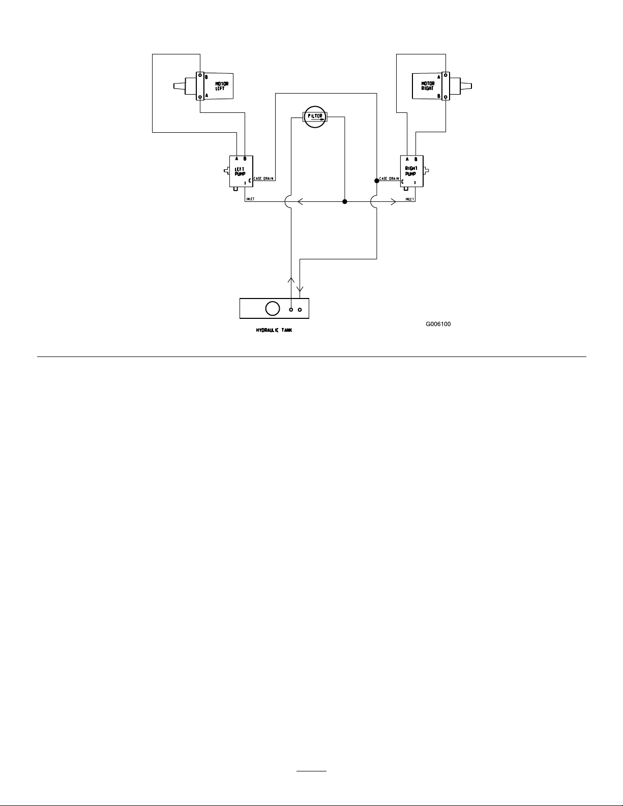
Schematics
HydraulicSchematic(Rev.A)
56
Page 57
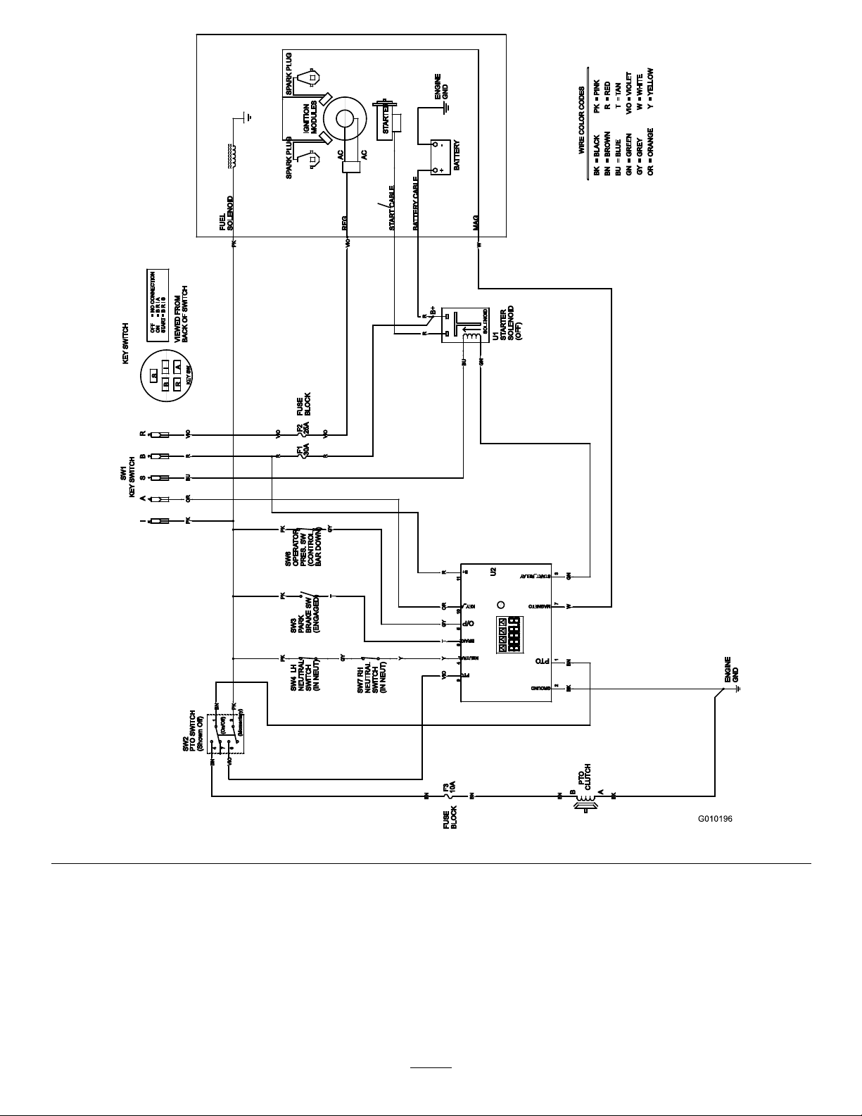
ElectricalSchematic(Rev.A)
57
Page 58

Notes:
58
Page 59

Notes:
59
Page 60

TheToroT otalCoverageWarranty
ALimitedWarranty(seewarrantyperiodsbelow)
Landscape
Contractor
Equipment(LCE)
ConditionsandProductsCovered
TheToroCompanyanditsafliate,ToroWarrantyCompany,pursuantto
anagreementbetweenthem,jointlypromisetotheoriginalpurchaser
torepairtheToroProductslistedbelowifdefectiveinmaterialsor
workmanship.
Thefollowingtimeperiodsapplyfromthedateofpurchasebytheoriginal
owner:
ProductsWarrantyPeriod
AllMowers
•Engine
Seeenginemanufacturer’swarranty
•Battery90daysPartsandLabor
1yearPartsonly
•BeltsandTires90days
•Attachments1year
21in.HeavyDutyMowers
Mid-SizeWalk-BehindMowers
GrandStand
TM
Mowers
•Frame
ZMaster
®
Z400,Z500Mowers4yearsor1,200hours
•Frame
ZMaster
®
G3Mowers
•Frame
1
SomeenginesusedonToroLCEProductsarewarrantedbytheenginemanufacturer .
2
Residentialusemeansuseoftheproductonthesamelotasyourhome.Useatmorethanone
locationisconsideredcommercialuseandthecommercialusewarrantywouldapply .
3
Whicheveroccursrst.
4
LifetimeFrameWarranty-Ifthemainframe,consistingofthepartsweldedtogethertoformthe
tractorstructurethatothercomponentssuchastheenginearesecuredto,cracksorbreaksin
normaluse,itwillberepairedorreplaced,atToro’ soption,underwarrantyatnocostforparts
andlabor.Framefailureduetomisuseorabuseandfailureorrepairrequiredduetorustor
corrosionarenotcovered.
1yearCommercialUse
2yearsResidentialUse
2years
5yearsor1,200hours
Lifetime(originalowneronly)
Lifetime(originalowneronly)
5yearsor1,200hours
Lifetime(originalowneronly)
2
3
4
3
4
3
4
Thiswarrantyincludesthecostofpartsandlabor,butyoumustpay
transportationcosts.
InstructionsforObtainingWarrantyService
IfyouthinkthatyourT oroProductcontainsadefectinmaterialsor
workmanship,followthisprocedure:
1.ContactanyAuthorizedToroServiceDealertoarrangeserviceattheir
dealership.Tolocateadealerconvenienttoyou,refertotheY ellow
Pagesofyourtelephonedirectory(lookunder“LawnMowers”)or
accessourwebsiteatwww.T oro.com.Youmayalsocallthenumbers
listedinitem#3tousethe24-hourToroDealerlocatorsystem.
2.Bringtheproductandyourproofofpurchase(salesreceipt)tothe
ServiceDealer.Thedealerwilldiagnosetheproblemanddetermine
ifitiscoveredunderwarranty.
3.IfforanyreasonyouaredissatisedwiththeServiceDealer’s
analysisorwiththeassistanceprovided,contactusat:
RLCCustomerCareDepartment
ToroWarrantyCompany
811 1LyndaleAvenueSouth
Bloomington,MN55420-1196
888-865-5676(U.S.Customers)
888-865-5691(Canadacustomers)
1
OwnerResponsibilities
YoumustmaintainyourT oroProductbyfollowingthemaintenance
proceduresdescribedintheOperator’sManual.Suchroutine
maintenance,whetherperformedbyadealerorbyyou,isatyourexpense.
ItemsandConditionsNotCovered
Thereisnootherexpresswarrantyexceptforspecialemission
systemandenginewarrantycoverageonsomeproducts.
Thisexpresswarrantydoesnotcoverthefollowing:
•Costofregularmaintenanceserviceorwearparts,suchaslters,
fuel,lubricants,tune-upparts,bladesharpening,brakeandclutch
adjustments.
•Anyproductorpartwhichhasbeenalteredormisusedandrequires
replacementorrepairduetonormalwear,accidents,orlackof
propermaintenance.
•Repairsnecessaryduetoimproperfuel,contaminantsinthefuel
system,orfailuretoproperlypreparethefuelsystempriortoany
periodofnon-useoverthreemonths.
•Pickupanddeliverycharges.
GeneralConditions
Allrepairscoveredbythesewarrantiesmustbeperformedbyan
AuthorizedToroServiceDealerusingToroapprovedreplacementparts.
NeitherTheToroCompanynorToroWarrantyCompanyisliablefor
indirect,incidentalorconsequentialdamagesinconnectionwiththe
useoftheT oroProductscoveredbythiswarranty,includingany
costorexpenseofprovidingsubstituteequipmentorserviceduring
reasonableperiodsofmalfunctionornon-usependingcompletion
ofrepairsunderthiswarranty.
Allimpliedwarrantiesofmerchantability(thattheproductistfor
ordinaryuse)andtnessforuse(thattheproductistforaparticular
purpose)arelimitedtothedurationoftheexpresswarranty
Somestatesdonotallowexclusionsofincidentalorconsequential
damages,orlimitationsonhowlonganimpliedwarrantylasts,so
theaboveexclusionsandlimitationsmaynotapplytoyou.
Thiswarrantygivesyouspeciclegalrights,andyoumayalsohaveother
rightswhichvaryfromstatetostate.
CountriesOtherthantheUnitedStatesorCanada
CustomerswhohavepurchasedToroproductsoutsidetheUnitedStatesorCanadashouldcontacttheirT oroDistributor(Dealer)toobtainguarantee
policiesforyourcountry,province,orstate.IfforanyreasonyouaredissatisedwithyourDistributor’sserviceorhavedifcultyobtainingguarantee
information,contacttheT oroimporter.Ifallotherremediesfail,youmaycontactusatToroWarrantyCompany.
374-0252RevB
 Loading...