

Page 1
PowerMax
®
HeavyDuty1028OHXE/1232OHXE
Snowthrower
ModelNo.38841—SerialNo.405348900andUp
ModelNo.38842—SerialNo.405348900andUp
FormNo.3432-507RevA
Operator'sManual
Introduction
Thismachineisintendedtobeusedbyresidential
homeowners.Itisdesignedprimarilyforremoving
snowfrompavedsurfaces,suchasdrivewaysand
sidewalks,andothersurfacesfortrafconresidential
orcommercialproperties.Itisnotdesignedfor
removingmaterialsotherthansnow.Usingthis
productforpurposesotherthanitsintendedusecould
provedangeroustoyouandbystanders.
Readthisinformationcarefullytolearnhowtooperate
andmaintainyourproductproperlyandtoavoid
injuryandproductdamage.Youareresponsiblefor
operatingtheproductproperlyandsafely.
Visitwww.T oro.comforproductsafetyandoperation
trainingmaterials,accessoryinformation,helpnding
adealer,ortoregisteryourproduct.
Wheneveryouneedservice,genuineToroparts,or
additionalinformation,contactanAuthorizedService
DealerorToroCustomerServiceandhavethemodel
andserialnumbersofyourproductready .Figure1
identiesthelocationofthemodelandserialnumbers
ontheproduct.Writethenumbersinthespace
provided.
ModelNo.
SerialNo.
Thismanualidentiespotentialhazardsandhas
safetymessagesidentiedbythesafety-alertsymbol
(Figure2),whichsignalsahazardthatmaycause
seriousinjuryordeathifyoudonotfollowthe
recommendedprecautions.
g000502
Figure2
Safety-alertsymbol
Thismanualuses2wordstohighlightinformation.
Importantcallsattentiontospecialmechanical
informationandNoteemphasizesgeneralinformation
worthyofspecialattention.
Important:Withyourmobiledevice,youcan
scantheQRcodeontheserialnumberdecal(if
equipped)toaccesswarranty,parts,andother
productinformation.
Figure1
1.Modelandserialnumberlocation
©2019—TheToro®Company
8111L yndaleAvenueSouth
Bloomington,MN55420
Registeratwww.Toro.com.
g296245
OriginalInstructions(EN)
PrintedintheUSA
AllRightsReserved
*3432-507*A
Page 2
Important:Ifyouareusingthismachineabove
1500m(5,000ft)foracontinuousperiod,ensure
thattheHighAltitudeKithasbeeninstalled
sothattheenginemeetsCARB/EPAemission
regulations.TheHighAltitudeKitincreases
engineperformancewhilepreventingspark-plug
fouling,hardstarting,andincreasedemissions.
Onceyouhaveinstalledthekit,attachthe
high-altitudelabelnexttotheserialdecalonthe
machine.ContactanyAuthorizedToroService
DealertoobtaintheproperHighAltitudeKitand
high-altitudelabelforyourmachine.T olocate
adealerconvenienttoyou,accessourwebsite
atwww.Toro.comorcontactourToroCustomer
CareDepartmentatthenumber(s)listedinyour
EmissionControlWarrantyStatement.Remove
thekitfromtheengineandrestoretheengineto
itsoriginalfactorycongurationwhenrunningthe
engineunder1500m(5,000ft).Donotoperatean
enginethathasbeenconvertedforhigh-altitude
useatloweraltitudes;otherwise,youcould
overheatanddamagetheengine.
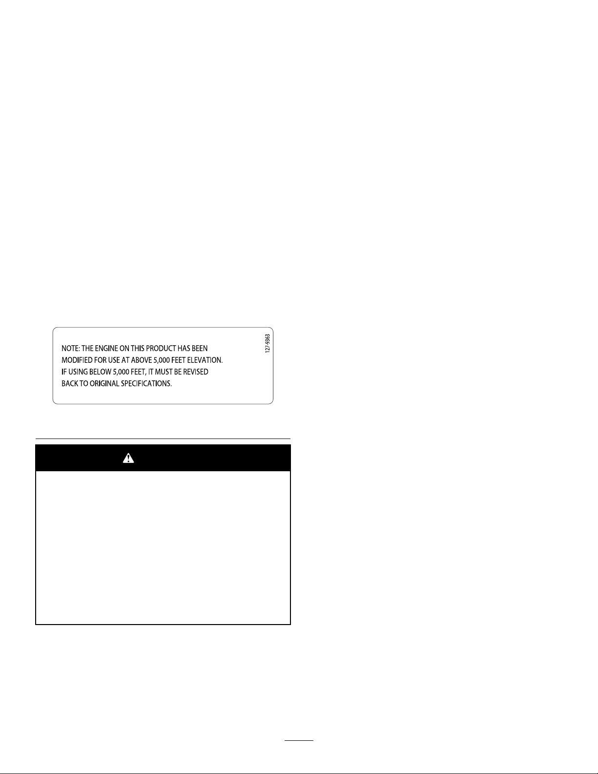
Ifyouareunsurewhetherornotyourmachinehas
beenconvertedforhigh-altitudeuse,lookforthe
followinglabel(Figure3).
decal127-9363
Figure3
WARNING
CALIFORNIA
Proposition65Warning
Theengineexhaustfromthisproduct
containschemicalsknowntotheStateof
Californiatocausecancer,birthdefects,
orotherreproductiveharm.
Useofthisproductmaycauseexposure
tochemicalsknowntotheStateof
Californiatocausecancer,birthdefects,
orotherreproductiveharm.
Contents
Introduction...............................................................1
Safety.......................................................................3
GeneralSafety...................................................3
SafetyandInstructionalDecals..........................3
Setup........................................................................5
1InstallingtheUpperHandle..............................5
2InstallingtheWheel-Clutch-Cable
Ends................................................................5
3InstallingtheTraction-ControlLinkage.............6
4InstallingtheChute-ControlRod......................6
5InstallingtheSnow-CleanoutTool....................7
6CheckingtheEngine-OilLevel.........................8
7CheckingtheTirePressure..............................8
8CheckingtheSkidsandScraper......................8
9CheckingtheOperationoftheTraction
Drive...............................................................8
ProductOverview...................................................10
Specications..................................................10
Attachments/Accessories.................................10
Operation.................................................................11
BeforeOperation..................................................11
BeforeOperationSafety....................................11
FillingtheFuelT ank...........................................11
DuringOperation..................................................11
DuringOperationSafety....................................11
StartingtheEngine...........................................12
ShuttingOfftheEngine.....................................14
OperatingtheHandwarmers.............................14
OperatingtheTractionDrive.............................14
UsingtheWheel-ClutchLevers.........................15
OperatingtheSpeedSelector...........................15
OperatingtheAuger/ImpellerDrive...................15
OperatingtheQuickStick®...............................16
ClearingaCloggedDischargeChute................16
OperatingTips.................................................17
AfterOperation....................................................17
AfterOperationSafety......................................17
PreventingFreeze-upafterUse........................17
Maintenance...........................................................18
RecommendedMaintenanceSchedule(s)...........18
MaintenanceSafety..........................................18
PreparingforMaintenance...............................18
CheckingtheEngine-OilLevel..........................19
CheckingandAdjustingtheSkidsand
Scraper.........................................................19
CheckingandAdjustingtheTraction
Cable............................................................20
CheckingandAdjustingtheAuger/Impeller
Cable............................................................20
CheckingtheAuger-Gearbox-OilLevel.............21
ChangingtheEngineOil...................................22
LubricatingtheHexShaft..................................22
ReplacingtheSparkPlug.................................23
ReplacingtheDriveBelts..................................24
ReplacingtheHeadlight....................................25
Storage...................................................................25
StorageSafety..................................................25
StoringtheMachine..........................................25
RemovingtheMachinefromStorage................26
Troubleshooting......................................................27
2
Page 3
Safety
x 3
1
2
3
4
5
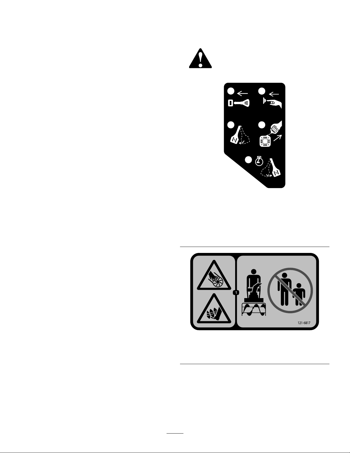
120-9805
SafetyandInstructional
Thismachinehasbeendesignedinaccordancewith
ANSI/OPEIB71.3specications.
GeneralSafety
Thisproductiscapableofamputatinghandsand
feetandofthrowingobjects.Alwaysfollowallsafety
instructionstoavoidseriouspersonalinjury .
•Readandunderstandthecontentsofthis
Operator’sManualbeforeyoustarttheengine.
Ensurethateveryoneusingthisproductknows
howtouseit,knowshowtoshutofftheengine
quickly,andunderstandsthewarnings.
•Shutofftheenginewheneveryouleavethe
operatingpositionforanyreason.
•Donotputyourhandsorfeetnearmovingparts
onthemachine.
•Donotoperatethemachinewithoutallguards
andothersafetyprotectivedevicesinplaceand
working.
•Keepclearofanydischargeopening.Keep
bystanders,especiallysmallchildren,outofthe
operatingarea.
•Neverallowchildrentooperatethemachine.
Decals
Safetydecalsandinstructionsare
easilyvisibletotheoperatorandare
locatednearanyareaofpotential
danger.Replaceanydecalthatis
damagedormissing.
decal120-9805
120-9805
1.Insertthekey.
2.Primetheengine3times.
3.Engagethechoke.
4.Pullthestartercord.
5.Oncetheengineisrunning,disengagethechoke.
decal121-6817
121-6817
1.Cutting/dismembermenthazardofhandorfoot,impeller
andauger—keepbystandersaway.
3
Page 4
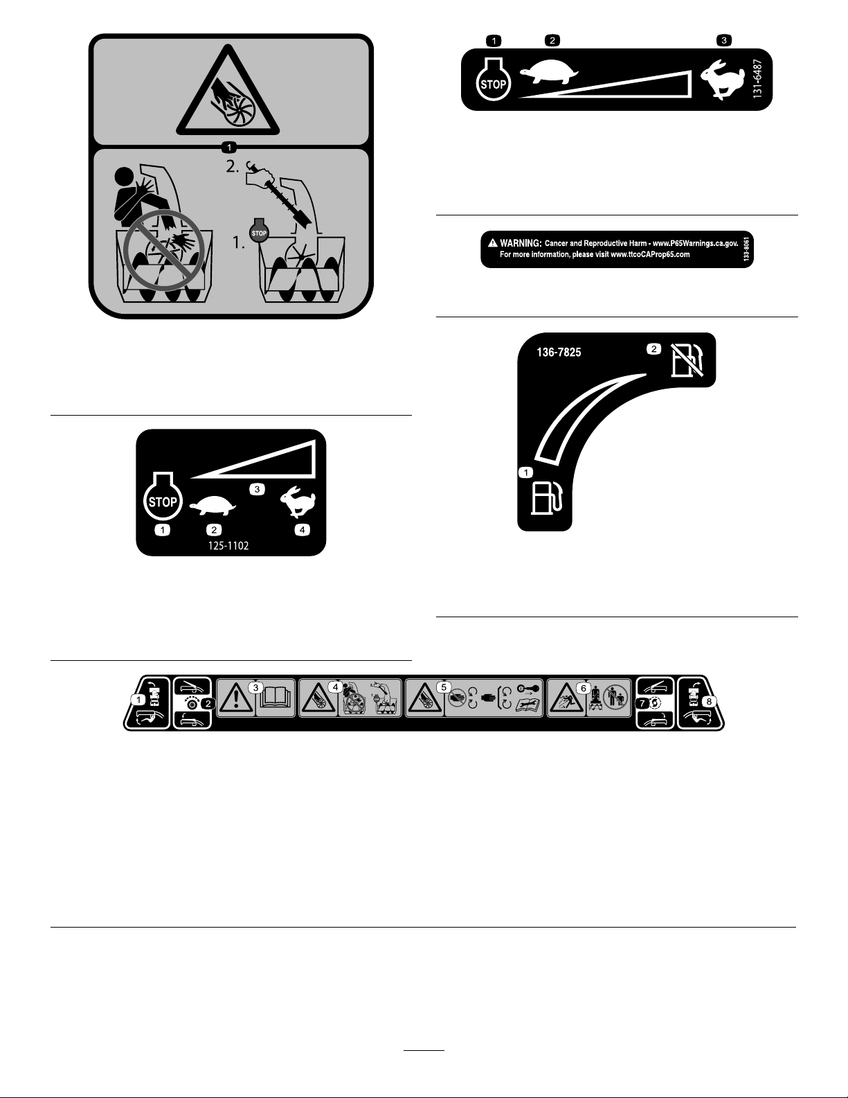
131-6487
Model38842only
decal131-6487
121-6847
1.Cutting/dismembermenthazardofthengersorhand,
impeller—donotplaceyourhandinthechute;shutoffthe
enginebeforeusingthetooltoclearthechute.
125-1102
Model38841only
decal121-6847
decal125-1102
1.Engine—shutoff
2.Slow
1.Fuel
3.Fast
decal133-8061
133-8061
decal136-7825
136-7825
Model38842only
2.Fuelshutoff
1.Engine—shutoff
2.Slow
3.Variablespeedcontrol
4.Fast
138-0650
1.Squeezethelowerlevertoturnleft.5.Cutting/dismembermentofngersorhand,impeller
2.Squeezetheupperlevertoengagethetractiondrive.
3.Warning—readtheOperator’sManual.7.Squeezetheupperlevertoengagetheimpeller.
4.Cutting/dismembermentofngersorhand,impellerblade—do
notplaceyourhandinthechute;shutofftheenginebefore
usingthetooltoclearthechute.
blade—keepawayfrommovingparts;keepallguardsand
shieldsinplace;removethekeyfromtheignitionbefore
servicingthemachine.
6.Thrownobjecthazard—keepbystandersaway.
8.Squeezethelowerlevertoturnright.
decal138-0650
4
Page 5
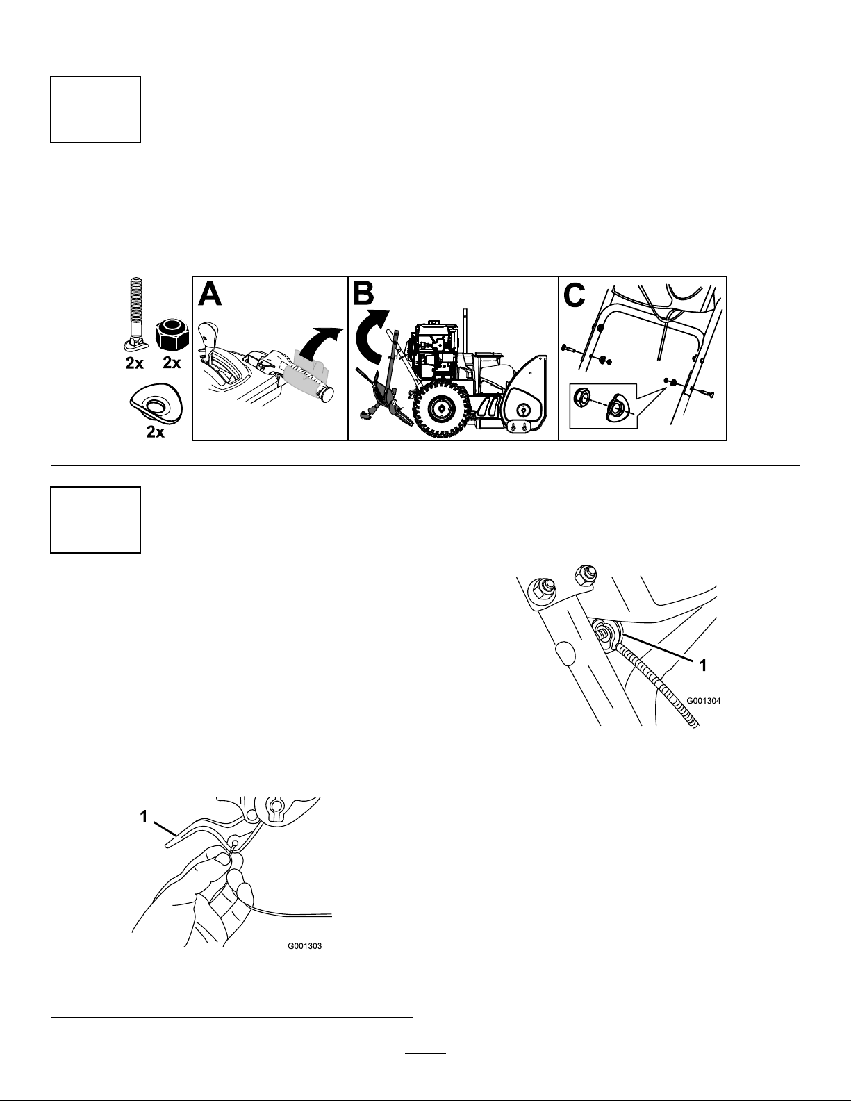
Setup
1
InstallingtheUpperHandle
NoPartsRequired
Procedure
g293415
2
Installingthe
Wheel-Clutch-CableEnds
NoPartsRequired
Procedure
1.Routeeithertheleftorrightcableendoverthe
lowerhandleandinsertthecableendintothe
holeinthecorrespondingwheel-clutchlever
(Figure5).
2.Removethenutandwasherfromthehandle,
attachthecableclamponthecabletothe
handle,installthewasherandthenut,and
tightenthenutbyhand(Figure6).
g001304
Figure6
1.Cableclamp(2)
Important:Ensurethatthecurvedsideof
thecableclampisagainstthehandleand
thatthecableisroutedbelowtheclampbolt.
Thecablemustbeinastraightlinefromthe
cableclamptothepointwhereitattachesto
thewheel-clutchlever.
1.Wheel-clutchlever
Figure5
3.Pullthecablejacketdowngentlyuntilthe
g001303
5
wheel-clutchleverisdownandtheslackisout
ofthecable,thentightenthecable-clampnut
securely(Figure7).
Page 6
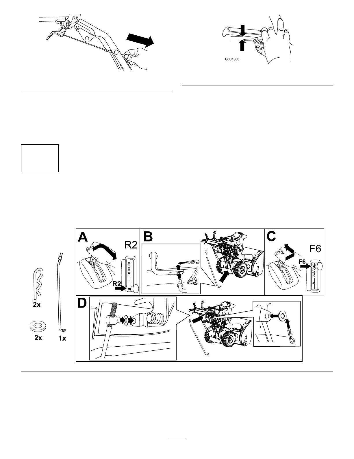
Figure7
g248021
Figure8
g001306
4.Squeezetheleverfully,thencheckthegap
betweenthebottomofthehandleandtheend
ofthewheel-clutchlever(Figure8).
3
InstallingtheTraction-ControlLinkage
NoPartsRequired
Procedure
Note:Thegapshouldbeapproximatelythe
thicknessofapencil(1/4inchor6mm).Ifitis
greater,loosenthecable-clampnut,slidethe
cablejacketupslightly,tightenthecable-clamp
nut,andcheckthegapagain.
5.Repeatsteps2through5fortheothercable.
g263628
6
Page 7
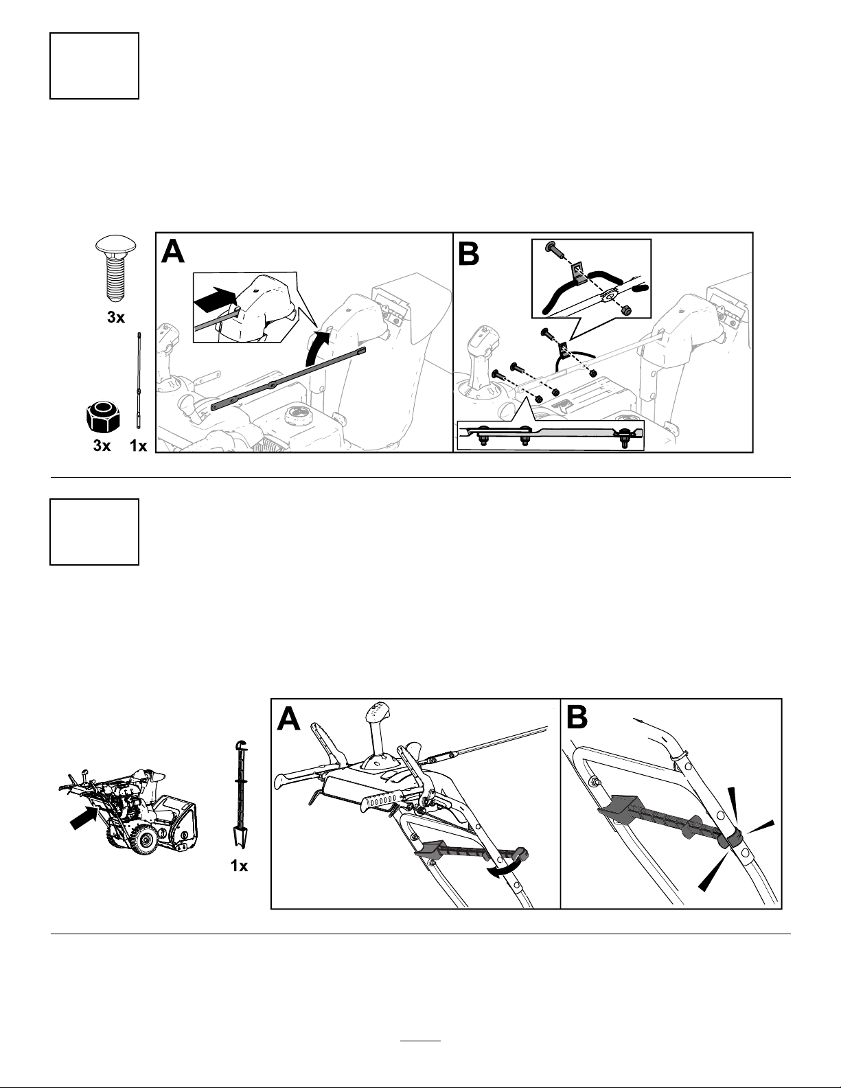
4
InstallingtheChute-ControlRod
NoPartsRequired
Procedure
g252615
5
InstallingtheSnow-CleanoutTool
NoPartsRequired
Procedure
g258663
7
Page 8

6
CheckingtheEngine-Oil
Level
NoPartsRequired
Procedure
Note:Yourmachinecomeswithoilintheengine
crankcase.Beforestartingtheengine,checktheoil
levelandaddoilifnecessary.
RefertoCheckingtheEngine-OilLevel(page19).
7
CheckingtheTirePressure
NoPartsRequired
Procedure
8
CheckingtheSkidsand
Scraper
NoPartsRequired
g252396
Procedure
RefertoCheckingandAdjustingtheSkidsand
Scraper(page19).
8
Page 9
5.MovethespeedselectortoPosition1;referto
OperatingtheSpeedSelector(page15).
9
CheckingtheOperationof
theTractionDrive
NoPartsRequired
Procedure
CAUTION
Ifthetractiondriveisnotproperlyadjusted,
themachinemaymoveinthedirection
oppositeofwhatyouintended,causinginjury
and/orpropertydamage.
Carefullycheckthetractiondriveandadjustit
properly,ifnecessary.
1.Starttheengine;refertoStartingtheEngine
(page12).
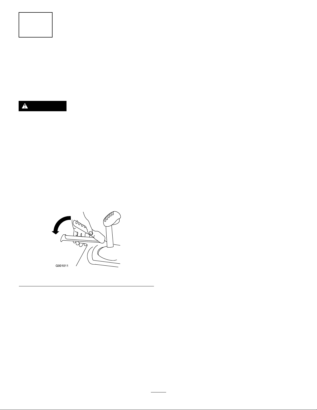
6.Squeezetheleft(traction)levertothehandgrip
(Figure13).
Themachineshouldmoveforward.Ifthe
machinedoesnotmoveormovesrearward,
completethefollowing:
A.Releasethetractionleverandshutoffthe
engine.
B.Disconnectthetrunnionfromthe
speed-selectorlever.
C.Turnthetrunnionupward(counterclockwise)
onthespeed-controlrod.
D.Connectthetrunniontothespeed-selector
lever.
7.Ifyoumadeanyadjustments,repeatthis
procedureuntilnoadjustmentsarerequired.
Important:Ifthemachinemoveswhenthe
tractionleverisinthereleasedposition,checkthe
tractioncable;refertoCheckingandAdjusting
theTractionCable(page20)ortakethemachine
toanAuthorizedServiceDealerforservice.
2.MovethespeedselectortoPositionR1;referto
OperatingtheSpeedSelector(page15).
3.Squeezetheleft(traction)levertothehandgrip
(Figure13).
Figure13
Themachineshouldmoverearward.Ifthe
machinedoesnotmoveormovesforward,
completethefollowing:
A.Releasethetractionleverandshutoffthe
engine.
B.Disconnectthetrunnionfromthe
speed-selectorlever.
g001011
C.Turnthetrunniondownward(clockwise)on
thespeed-controlrod.
D.Connectthetrunniontothespeed-selector
lever.
4.Releasethetractionlever.
9
Page 10
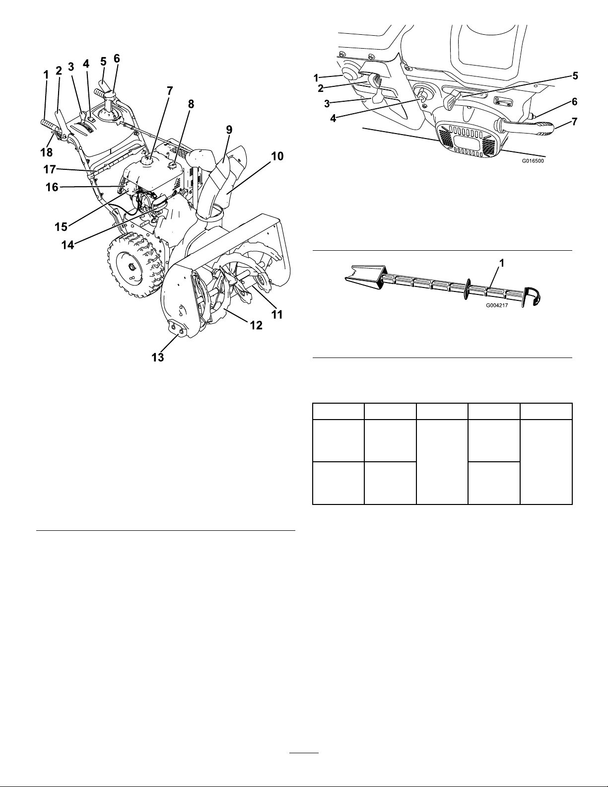
ProductOverview
g016500
Figure15
1.Primer5.Throttle
2.Key
3.Choke
4.Fuel-shutoffvalve
6.Oil-drainplug
7.Recoil-starthandle
g004217
Figure16
Figure14
1.Handgrip(2)
2.Auger/impellerlever11.Scraper
3.Speed-selectorlever
4.Handwarmerswitch
5.Tractionlever14.Headlight
6.QuickStick®
discharge-chutecontrol
7.Fuel-tankcap16.Electric-startplug-in
8.Oil-lltube/dipstick17.Snow-cleanouttool
9.Chutedeector18.Wheel-clutchlever(2)
10.Dischargechute
12.Auger
13.Skid(2)
15.Electric-startbutton
1.Snow-cleanouttool(attachedtothehandle)
g247809
Specications
ModelWeightLengthWidthHeight
124.7kg74cm
38841
38842
Attachments/Accessories
AselectionofToroapprovedattachmentsand
accessoriesisavailableforusewiththemachine
toenhanceandexpanditscapabilities.Contact
yourAuthorizedServiceDealerorauthorizedT oro
distributororgotowww.T oro.comforalistofall
approvedattachmentsandaccessories.
(275lb)
136.1kg84cm
(300lb)
160cm
(63
inches)
(29
inches)
(33
inches)
114cm
(45
inches)
Toensureoptimumperformanceandcontinuedsafety
certicationofthemachine,useonlygenuineToro
replacementpartsandaccessories.Replacement
partsandaccessoriesmadebyothermanufacturers
couldbedangerous,andsuchusecouldvoidthe
productwarranty.
10
Page 11
Operation
Note:Determinetheleftandrightsidesofthe
machinefromthenormaloperatingposition.
BeforeOperation
BeforeOperationSafety
GeneralSafety
•Forelectric-startmodelsonly:Useextension
cordsandreceptaclesasspeciedinthemanual.
Inspecttheelectricalcordbeforepluggingitinto
apowersource.Ifthecordisdamaged,replace
it.Unplugthepowercordwheneveryouarenot
startingthemachine.
•Wearappropriateclothing,includingeye
protection;longpants;substantial,slip-resistant
footwear;andhearingprotection.Tiebacklong
hair,securelooseclothing,anddonotwearloose
jewelry.
FillingtheFuelTank
•Forbestresults,useonlyclean,fresh(lessthan
30daysold),unleadedgasolinewithanoctane
ratingof87orhigher((R+M)/2ratingmethod).
•Oxygenatedfuelwithupto10%ethanolor15%
MTBEbyvolumeisacceptable.
•Donotuseethanolblendsofgasoline(such
asE15orE85)withmorethan10%ethanolby
volume.Performanceproblemsand/orengine
damagemayresultwhichmaynotbecovered
underwarranty.
•Donotusegasolinecontainingmethanol.
•Donotstorefueleitherinthefueltankorfuel
containersoverthewinterunlessyouuseafuel
stabilizer.
•Donotaddoiltogasoline.
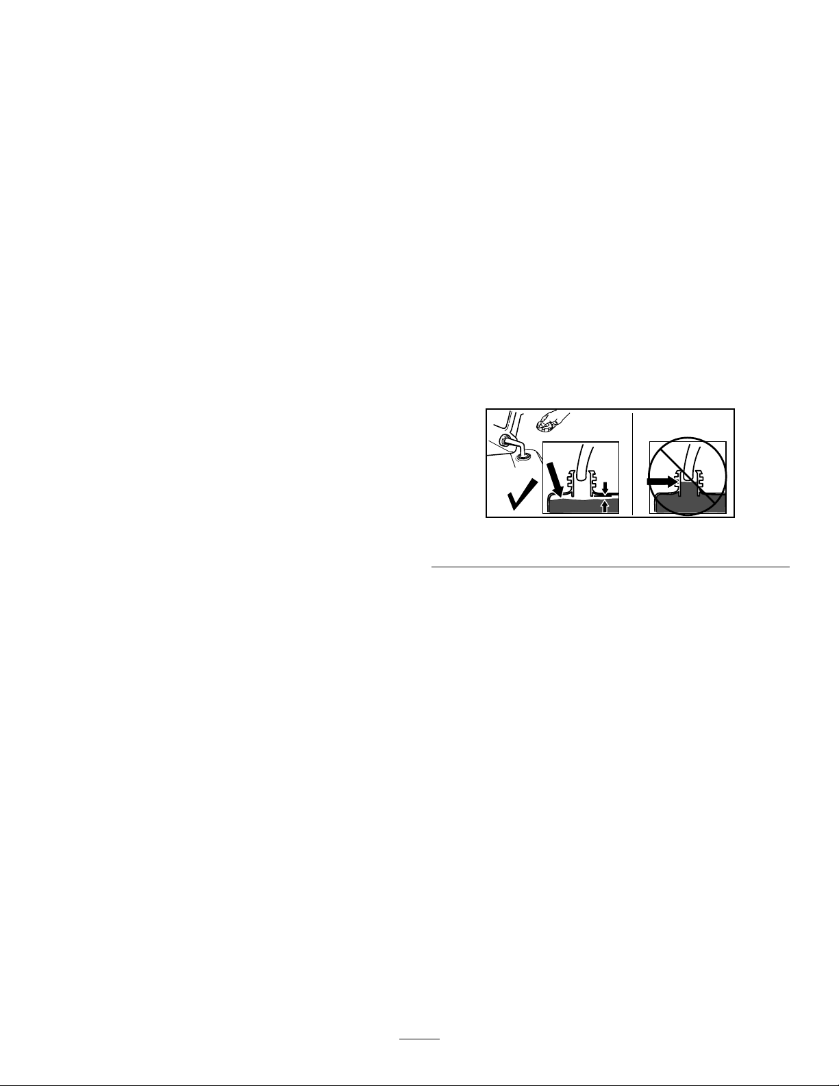
Donotllabovethebottomofthefueltankneck
(Figure17).
•Thoroughlyinspecttheareawhereyouwillusethe
machine,andremovealldoormats,sleds,boards,
wires,andotherforeignobjects.
•Ifashield,safetydevice,ordecalisdamaged,
illegible,ormissing,repairorreplaceitbefore
beginningoperation.Also,tightenanyloose
fasteners.
•Two-stagemodelsonly:Adjustthecollector
housingheighttoclearagravelorcrushed-rock
surface.
FuelSafety
Fuelisextremelyammableandexplosive.Areor
explosionfromfuelcanburnyouandothers.
•Topreventastaticchargefromignitingthefuel,
placethecontainerand/ormachineontheground
beforelling,notinavehicleoronanobject.
•Fillthefueltankoutdoorswhentheengineiscold.
Replacethefuelcapsecurelyandwipeupspills.
•Donothandlefuelwhensmokingoraroundan
openameorsparks.
•Storefuelinanapprovedfuelcontainer,outofthe
reachofchildren.
•Whenfuelisinthetank,tipthemachineonlyas
directedintheinstructions.
•Ifyouspillfuelonyourclothing,changeyour
clothingimmediately.
g216203
Figure17
Important:Forbestresults,purchaseonlythe
quantityoffuelthatyouexpecttousein30days.
Otherwise,youmayusefuelstabilizer/conditioner
inthemachineatalltimestokeepthefuelfresh
longerwhenusedasdirectedbythefuel-stabilizer
manufacturer.
DuringOperation
DuringOperationSafety
GeneralSafety
•Shutofftheenginebeforeuncloggingthe
machineandalwaysuseastickorthe
snow-cleanouttool(ifprovided).
•Staybehindthehandlesandawayfromthe
dischargeopeningwhileoperatingthemachine.
Keepyourface,hands,feet,andanyotherpart
ofyourbodyorclothingawayfrommovingor
rotatingparts.
11
Page 12

•Neverdirectthedischargetowardpeopleorareas
wherepropertydamagecanoccur.
•Useyourfullattentionwhileoperatingthe
machine.Donotengageinanyactivitythat
causesdistractions;otherwise,injuryorproperty
damagemayoccur.
•Exercisecautiontoavoidslippingorfalling,
especiallywhenoperatingthemachineinreverse.
•Alwaysbesureofyourfooting,andkeeparm
holdonthehandles.Walk;neverrun.
•Exerciseextremecautionwhenoperatingthe
machineonaslope.
•Donotoperatethemachinewithoutgoodvisibility
orlight.
•Lookbehindandusecarewhenbackingupthe
machine.
•Whennotactivelyclearingsnow,disengagepower
totheauger.
•Exerciseextremecautionwhenoperatingthe
machineonorcrossinggraveldrives,walks,or
roads.Stayalertforhiddenhazardsortrafc.
•Neverattempttomakeanyadjustmentswhile
theengineisrunning,exceptasdirectedinthe
instructions.
•Afterstrikingaforeignobject,shutofftheengine,
removethekey,andinspectthemachinefor
damage.Repairanydamagebeforestartingthe
machine.
•Ifthemachinestartstovibrateabnormally,shutoff
theengineandcheckimmediatelyforthecause.
•Donotruntheengineindoors;exhaustfumesare
dangerous.
•Donotoverloadthemachinecapacityby
attemptingtoclearsnowattoofastarate.
•Disengageallclutchesandshiftintoneutralbefore
startingtheengine.
•Shutofftheenginewheneveryouleavethe
operatingposition,beforeclearingorunclogging
thecollector,impeller,ordischargechute,and
whenmakinganyrepairs,adjustments,or
inspections.
•Neveroperatethemachineathightransport
speedsonslipperysurfaces.
StartingtheEngine
ElectricStart
Note:Tousetheelectricstarter(electric-startmodelsonly),connectapowercordtotheplug-inrstandthen
toapoweroutlet.UseonlyaUL-listed,16-gaugeextensioncordrecommendedforoutdoorusethatisnot
longerthan15m(50ft).
WARNING
Theelectricalcordcanbecomedamaged,causingashockorre.
Thoroughlyinspecttheelectricalcordbeforeusingthemachine.Ifthecordisdamaged,do
notuseit.Replaceorrepairthedamagedcordimmediately.ContactanAuthorizedService
Dealerforassistance.
CAUTION
Ifyouleavethemachinepluggedintoapoweroutlet,someonecaninadvertentlystartthe
machineandinjurepeopleordamageproperty.
Unplugthepowercordwheneveryouarenotstartingthemachine.
12
Page 13
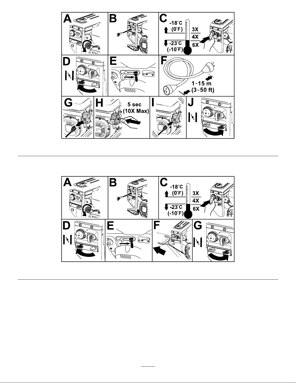
RecoilStart
g257504
Figure18
g257505
Figure19
13
Page 14
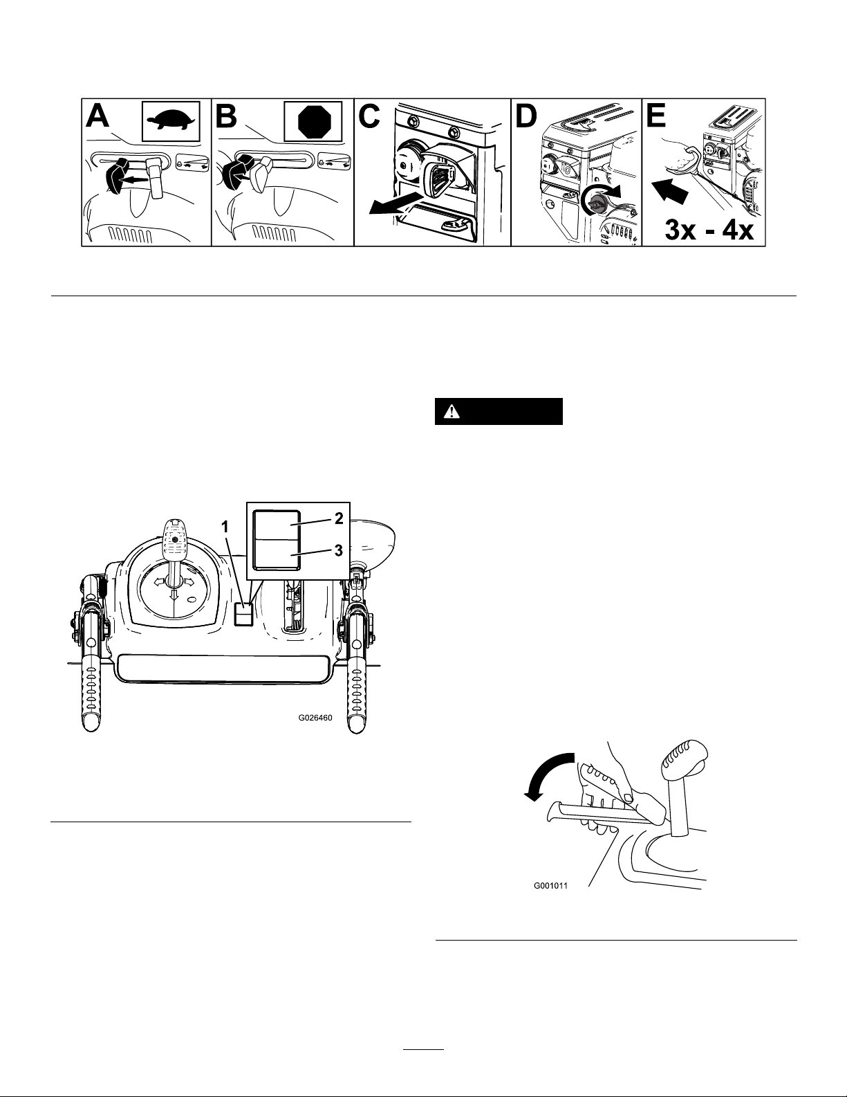
ShuttingOfftheEngine
Important:Waitforallmovingpartstostopbeforeleavingtheoperatingposition.
Figure20
g252411
Operatingthe
Handwarmers
Operatethehandwarmersasfollows:
•PresstheswitchtotheONpositiontoturnonthe
handwarmers.
•PresstheswitchtotheOFFpositiontoturnoffthe
handwarmers.
Figure21
OperatingtheTraction
Drive
CAUTION
Ifthetractiondriveisnotproperlyadjusted,
themachinemaymoveinthedirection
oppositeofwhatyouintended,causinginjury
and/orpropertydamage.
Carefullycheckthetractiondriveandadjust
itproperly,ifnecessary;refertoChecking
andAdjustingtheTractionCable(page20)for
moreinformation.
Important:Ifthemachinemoveswhenthe
tractionleverisinthereleasedposition,checkthe
tractioncable;refertoCheckingandAdjusting
theTractionCable(page20)ortakethemachine
toanAuthorizedServiceDealerforservice.
1.Toengagethetractiondrive,squeezetheleft
(traction)levertothehandgrip(Figure22).
g026460
1.On/Offswitch3.OFFposition
2.ONposition
g001011
Figure22
2.Tostopthetractiondrive,releasethetraction
lever.
14
Page 15
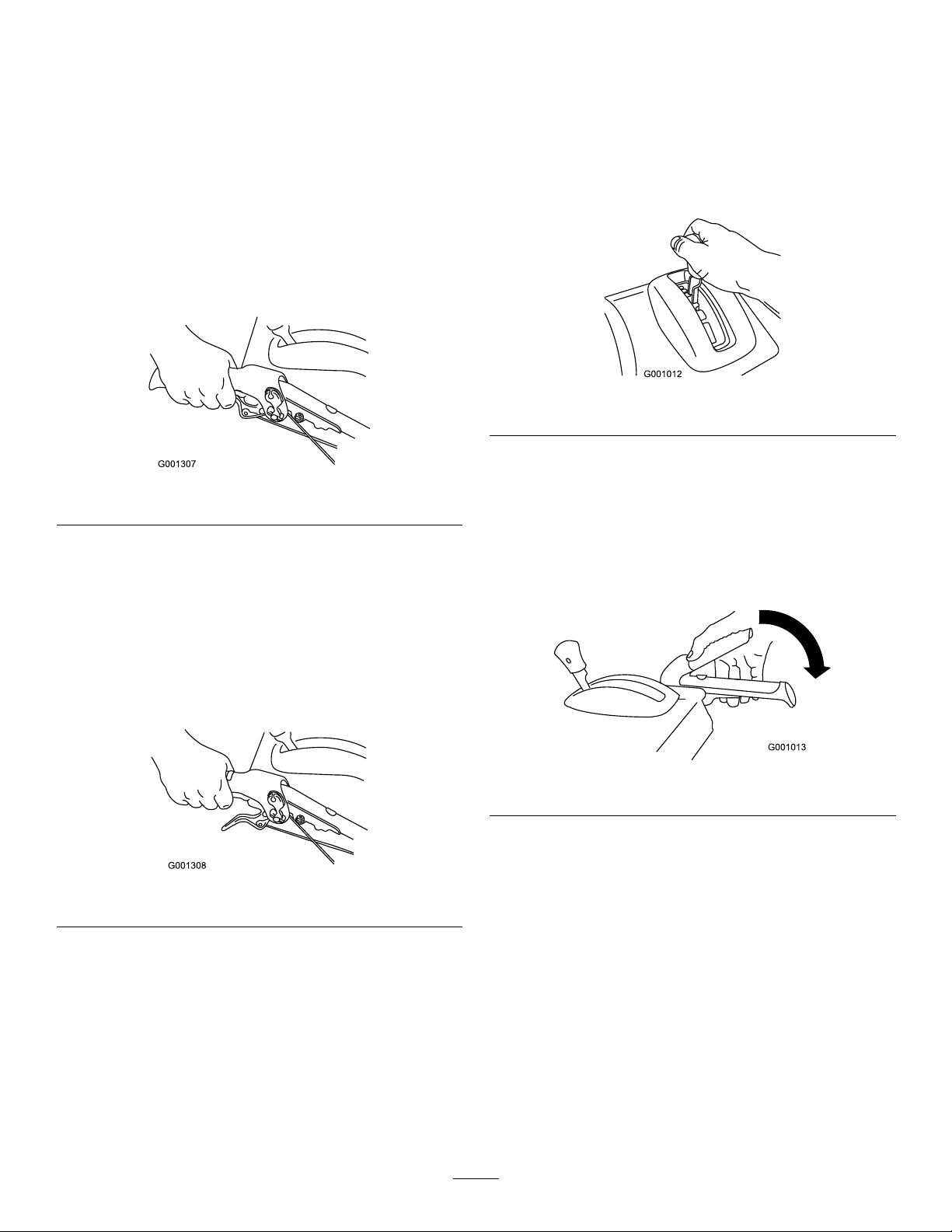
UsingtheWheel-Clutch
OperatingtheSpeed
Levers
Thewheel-clutchleversallowyoutomomentarily
disengagethedriveto1orbothwheelswiththe
traction-driveleverstillengaged.Thisenablesyouto
turnandmaneuverthemachineeasily.
Note:Holdingdownthetractionleveragainstthe
handleengagesthetractiondrivetobothwheels.
Toturnthemachinetotheright,liftuptheright
wheel-clutchleverandsqueezeittowardthehandle
(Figure23).
Figure23
Selector
Thespeedselectorhas6forwardand2reverse
gears.T ochangespeeds,releasethetractionlever
andshiftthespeed-selectorlevertothedesired
position(Figure25).Theleverlocksinanotchat
eachspeedselection.
g001012
Figure25
g001307
Operatingthe
Auger/ImpellerDrive
Note:Thisdisengagesthedrivetotherightwheel
whiletheleftwheelcontinuesdriving,andthemachine
turnstotheright.
Note:Similarly,squeezingtheleftwheel-clutchlever
turnsthemachinetotheleft.
Whenyoucompletetheturn,releasethewheel-clutch
lever,andthedrivere-engagesbothwheels(Figure
24).
Figure24
Momentarilysqueezingandreleasingtheleftorright
wheel-clutchleveralsoallowsforsteeringadjustments
tokeepthemachinegoinginastraightline,especially
indeepsnow.
Squeezingbothwheel-clutchleverssimultaneously
disengagesthedrivetobothwheels.Thisenables
youtomanuallymovethemachinebackwardwithout
stoppingtoshiftitintoareversegear.Italsoallows
youtomaneuverandtransportthemachinemore
easilywhentheengineisnotrunning.
1.Toengagetheauger/impellerdrive,squeeze
theright(auger/impeller)levertothehandgrip
(Figure26).
g001013
Figure26
2.Tostoptheaugerandimpeller,releasetheright
lever.
g001308
Important:Whenyouengageboththe
auger/impellerleverandthetractionlever,
thetractionleverlockstheauger/impeller
leverdown,freeingyourrighthand.To
releasebothlevers,simplyreleasetheleft
(traction)lever.
3.Iftheaugerandimpellercontinuetorotatewhen
youreleasetheauger/impellerlever,donot
operatethemachine.Checktheauger/impeller
cable;refertoCheckingandAdjustingthe
Auger/ImpellerCable(page20)andadjustitif
necessary.Otherwise,takethemachinetoan
AuthorizedServiceDealerforservice.
15
Page 16
WARNING
Iftheaugerandimpellercontinue
torotatewhenyoureleasethe
auger/impellerlever,youcouldseriously
injureyourselforothers.
Donotoperatethemachine.Takeittoan
AuthorizedServiceDealerforservice.
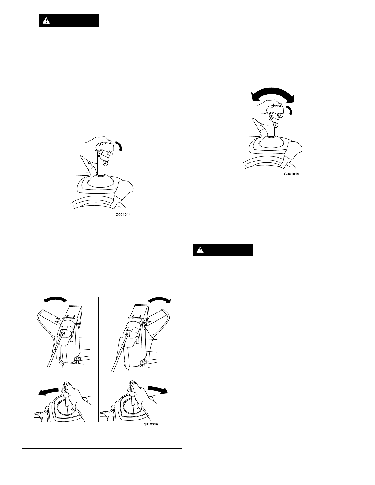
OperatingtheQuickStick®
HoldthebluetriggercapdowntousetheQuickStick
tomovethedischargechuteandthechutedeector.
Releasethetriggercaptolockthedischargechute
andchutedeectorintoposition(Figure27).
Ifthechutedoesnotturnasfartotheleftasitdoesto
theright,ensurethatthecableisroutedtotheinside
ofthehandles.
MovingtheChuteDeector
HoldthebluetriggercapdownandmovetheQuick
Stickforwardtolowerthechutedeector;moveit
rearwardtoraisethechutedeector(Figure29).
g001016
Figure29
Figure27
MovingtheDischargeChute
HoldthebluetriggercapdownandmovetheQuick
Sticktothelefttomovethedischargechutetothe
left;movetheQuickSticktotherighttomovethe
dischargechutetotheright(Figure28).
g001014
ClearingaClogged
DischargeChute
WARNING
Iftheauger/impellerisrunningbutthereisno
snowcomingoutofthedischargechute,the
dischargechutemaybeclogged.
Neveruseyourhandstoclearaclogged
dischargechute.Thiscouldresultinpersonal
injury.
•Tounclogthedischargechute,stayinthe
operatingpositionandreleasetheleft(traction)
lever.Whilerunningtheauger/impeller,pushdown
onthehandlestoraisethefrontofthemachinea
fewcentimeters(inches)offthepavement.Then
liftthehandlesquicklytobumpthefrontofthe
machineonthepavement.Repeatifnecessary
untilastreamofsnowcomesoutthedischarge
chute.
•Ifyoucannotunclogthedischargechuteby
bumpingthefrontofthemachine,shutoffthe
engine,waitforallmovingpartstostop,and
usethesnow-cleanouttool(Figure16).
Figure28
g018894
16
Important:Uncloggingthedischargechute
bybumpingthefrontofthemachineonthe
pavementmaycausetheskidstomove.Adjust
theskidsandtightentheskidboltssecurely;
Page 17

refertoCheckingandAdjustingtheSkidsand
Scraper(page19).
AfterOperation
OperatingTips
DANGER
Whenthemachineisinoperation,theimpeller
andaugerrotateandcaninjureoramputate
handsorfeet.
•Beforeadjusting,cleaning,inspecting,
troubleshooting,orrepairingthemachine,
shutofftheengineandwaitforallmoving
partstostop.Disconnectthewirefrom
thesparkplugandkeepitawayfromthe
plugtopreventsomeonefromaccidentally
startingtheengine.
•Removeanobstructionfromthedischarge
chute;refertoClearingaClogged
DischargeChute(page16).Usethe
snow-cleanouttool(Figure17),notyour
hands,toremoveanobstructionfromthe
dischargechute.
•Staybehindthehandlesandawayfrom
thedischargeopeningwhileoperatingthe
machine.
AfterOperationSafety
GeneralSafety
•Neverstorethemachinewithfuelinthefuel
tankinsideabuildingwhereignitionsourcesare
present,suchashotwaterheaters,spaceheaters,
orclothesdryers.Allowtheenginetocoolbefore
storingthemachineinanyenclosure.
•Whenstoringthemachineformorethan30
days,refertoStorage(page25)forimportant
information.
•Runthemachineafewminutesafterthrowing
snowtopreventfreeze-upofthecollectorand
impeller.
PreventingFreeze-upafter
Use
•Insnowyandcoldconditions,somecontrolsand
movingpartsmayfreeze.Donotuseexcessive
forcewhentryingtooperatefrozencontrols.
Ifyouhavedifcultyoperatinganycontrolorpart,
starttheengineandletitrunforafewminutes.
•Keepyourface,hands,feet,andanyother
partofyourbodyorclothingawayfrom
concealed,moving,orrotatingparts.
WARNING
Theimpellercanthrowstones,toys,andother
foreignobjectsandcauseseriouspersonal
injurytoyouorbystanders.
•Keeptheareatobeclearedfreeofall
objectsthattheaugercouldpickupand
throw.
•Keepallchildrenandpetsawayfromthe
areaofoperation.
•AlwayssetthethrottletotheFASTpositionwhen
throwingsnow.
•Iftheengineslowsdownunderaloadorthe
wheelsslip,shiftthemachineintoalowergear.
•Ifthefrontofthemachineridesup,shiftthe
machineintoalowergear.Ifthefrontcontinuesto
rideup,liftuponthehandles.
•Afterusingthemachine,lettheenginerunfor
afewminutestopreventmovingpartsfrom
freezing.Engagetheauger/impellertoclearany
remainingsnowfrominsidethehousing.Rotate
theQuickSticktopreventitfromfreezing.Shutoff
theengine,waitforallmovingpartstostop,and
removealliceandsnowfromthemachine.
•Withtheengineoff,pulltherecoil-starthandle
severaltimesandpushtheelectric-startbutton
oncetopreventtherecoilstarterandelectric
starterfromfreezingup.
17
Page 18

Maintenance
RecommendedMaintenanceSchedule(s)
MaintenanceService
Interval
Aftertherst2hours
Aftertherst5hours
Beforeeachuseordaily
Every50hours
Every100hours
Yearly
Yearlyorbeforestorage
MaintenanceProcedure
•Inspectthetractioncableandadjustitifnecessary.
•Inspecttheauger/impellercableandadjustitifnecessary .
•Changetheengineoil.
•Checktheengine-oillevelandaddoilifnecessary.
•Changetheengineoil.Changetheengineoilevery25operatinghourswhen
operatingtheengineunderaheavyload.
•Replacethesparkplug.
•Checktheskidsandthescraperandadjustthemifnecessary .
•Inspectthetractioncableandadjustorreplaceitifnecessary.
•Inspecttheauger/impellercableandadjustorreplaceitifnecessary.
•Checktheauger-gearboxoilandaddoilifnecessary.
•Lubricatethehexshaft.
•Checktheairpressureinthetiresandinatethemto116to137kPa(17to20psi).
•Drainthefuelandruntheenginetodryoutthefueltankandthecarburetoratthe
endoftheseason.
•HaveanAuthorizedServiceDealerinspectandreplacethetractiondrivebeltand/or
theauger/impellerdrivebelt,ifnecessary.
MaintenanceSafety
Readthefollowingsafetyprecautionsbefore
performinganymaintenanceonthemachine:
•Shutofftheengine,removethekey ,andwait
forallmovementtostopbeforeyouleavethe
operator’sposition.Allowthemachinetocool
beforeadjusting,servicing,cleaning,orstoringit.
•Alwaysweareyeprotectionwhileperformingan
adjustmentorrepairtoprotectyoureyesfrom
foreignobjectsthatthemachinemaythrow.
•Checkallfastenersatfrequentintervalsforproper
tightnesstoensurethatthemachineisinsafe
workingcondition.
•Donotchangethegovernorsettingsontheengine.
PurchaseonlygenuineTororeplacementparts
andaccessories.
PreparingforMaintenance
1.Movethemachinetoalevelsurface.
2.Shutofftheengineandwaitforallmovingparts
tostop.
3.Disconnectthespark-plugwire.Referto
ReplacingtheSparkPlug(page23).
18
Page 19
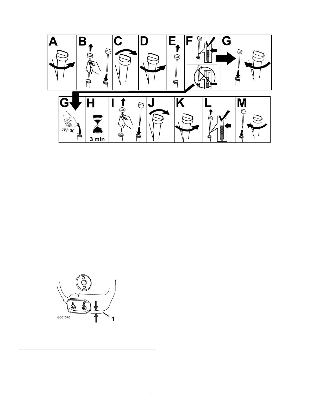
CheckingtheEngine-OilLevel
ServiceInterval:Beforeeachuseordaily—Checktheengine-oillevelandaddoilifnecessary.
g257528
CheckingandAdjustingthe
SkidsandScraper
ServiceInterval:Y early—Checktheskidsand
thescraperandadjustthemif
necessary.
Checktheskidsandthescrapertoensurethatthe
augerdoesnotcontactthepavedorgravelsurface.
Adjusttheskidsandthescraperasneededto
compensateforwear.
1.Checkthetirepressure;referto7Checkingthe
TirePressure(page8).
2.Loosenthenutsthatsecurebothskidstothe
augersidesuntiltheskidsslideupanddown
easily.
Note:Ifthepavementiscracked,rough,or
uneven,adjusttheskidstoraisethescraper.For
gravelsurfaces,adjusttheskidsfurtherdownto
preventthemachinefrompickinguprocks.
4.Movetheskidsdownuntiltheyareevenwith
theground.
5.Firmlytightenthenutsthatsecurebothskids
totheaugersides.
Note:Toquicklyadjusttheskidsiftheyloosen,
supportthescraper3mm(1/8inch)offthe
pavement,thenadjusttheskidsdowntothe
pavement.
Note:Iftheskidsbecomeexcessivelyworn,
youcanturnthemoverandsettheunusedside
towardthepavement.
Figure31
1.3mm(1/8inch)
Important:Theaugerbladesmustbe
supportedabovethegroundbytheskids.
3.Ensurethatthescraperis3mm(1/8inch)above
andparalleltoalevelsurface.
g001570
19
Page 20
CheckingandAdjustingthe
CheckingandAdjustingthe
TractionCable
ServiceInterval:Aftertherst2hours—Inspect
thetractioncableandadjustitif
necessary.
Yearly—Inspectthetractioncableandadjustor
replaceitifnecessary.
Ifthemachinedoesnotdriveintheforwardorreverse
speedsoritdriveswhenyoureleasethetractionlever,
adjustthetractioncable.
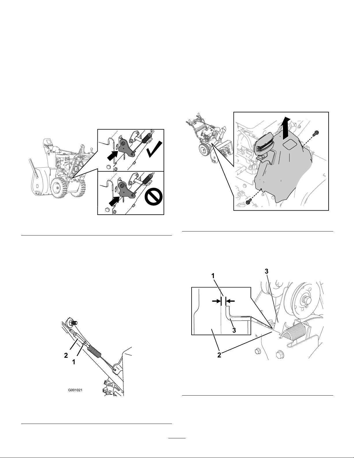
Withthetractionleveldisengaged,ensurethatthe
bottomofthetraction-cablebracketistouchingthe
frameofthemachine(Figure30).
Auger/ImpellerCable
ServiceInterval:Aftertherst2hours—Inspectthe
auger/impellercableandadjustitif
necessary.
Yearly—Inspecttheauger/impellercableand
adjustorreplaceitifnecessary.
1.Removethe2screwsthatareholdingthebelt
coverinplace(Figure34).
2.Removethebeltcover(Figure34).
Figure32
Ifthebottomofthetraction-cablebracketisnot
touchingtheframeofthemachine,theleft(traction)
cableisnotproperlyadjusted.
Toadjustthetractioncable,dothefollowing:
1.Loosenthejamnut.
2.Loosenortightentheturnbuckletountilthe
cableistaughtandthebottomofthebracket
touchestheframeofthemachine.
3.Tightenthejamnut(Figure33).
g259431
Figure34
g260066
3.Withtheauger/impellerleverdisengaged,
ensurethatthegapbetweentheaugerclutch
armandtheframeofthemachineis1.5mm
(1/16inch)asshowninFigure35.
g260108
Figure35
1.1.5mm(1/16inch)
2.Frame
3.Augerclutcharm
Figure33
1.Jamnut2.Turnbuckle
g001021
4.Iftheauger/impellercableisnotproperly
adjusted,dothefollowingsteps:
5.Loosenthejamnut(Figure36).
20
Page 21
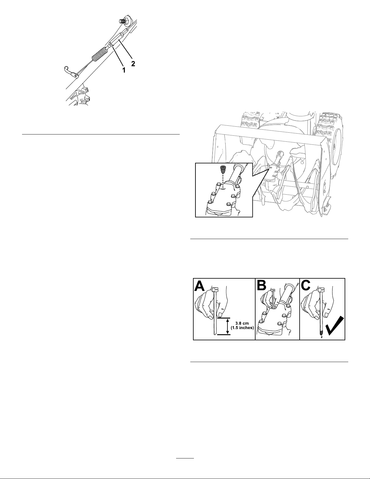
Figure36
1.Jamnut2.Turnbuckle
6.Loosenortightentheturnbucklethatadjuststhe
tensiononthecable(Figure36).
7.Adjusttheturnbuckleuntilyouobtaintheproper
gap.
8.Tightenthejamnut.
9.Insertthe2screwsthatyoupreviouslyremoved
onthebeltcover.
Checkingthe
Auger-Gearbox-OilLevel
ServiceInterval:Y early—Checktheauger-gearbox
oilandaddoilifnecessary.
1.Movethemachinetoalevelsurface.
2.Cleantheareaaroundthepipeplugandremove
thepipeplugfromthegearbox(Figure37).
Note:Ifneeded,useplierstoassistinremoving
g260109
thepipeplug.
10.Iftheauger/impellercableisproperlyadjusted
butaproblemremains,contactanAuthorized
ServiceDealer.
g257725
Figure37
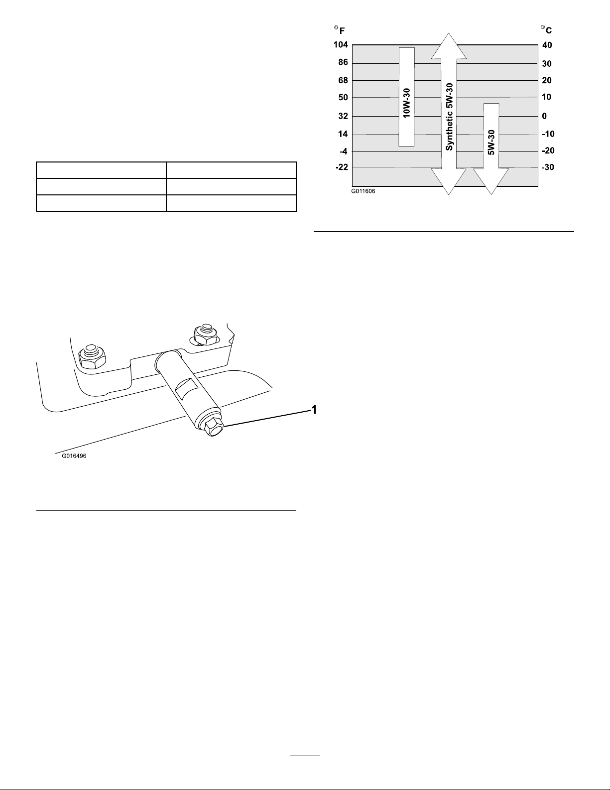
3.Checktheoillevelusingasuitablemeasuring
device,suchasacleancabletie.Theoilshould
beapproximately3.8cm(1.5inches)belowthe
lleropening(Figure38).
g257737
Figure38
4.Iftheoillevelislow,addGL-5orGL-6,SAE
85-95EPgearoillubricanttothegearbox,then
checktheoillevelagain.
Note:Donotusesyntheticoil.
5.Installthepipepluginthegearbox.
21
Page 22
ChangingtheEngineOil
ServiceInterval:Aftertherst5hours—Changethe
engineoil.
Every50hours—Changetheengineoil.
Changetheengineoilevery25operatinghours
whenoperatingtheengineunderaheavyload.
Ifpossible,runtheengineforafewminutesbefore
changingtheoilbecausewarmoilowsbetterand
carriesmorecontaminants.
Engineoilcapacity
OilviscosityRefertoFigure40.
APIserviceclassicationSJorhigher
0.95L(32oz)*
*Thereisresidualoilinthecrankcaseafteryoudrain
theoil.Donotpourtheentirecapacityofoilintothe
crankcase.Fillthecrankcasewithoilasdirectedin
thefollowingsteps.
1.Movethemachinetoalevelsurface.
2.Cleantheareaaroundtheoil-draincap(Figure
39).
Figure39
1.Oil-draincap
g011606
Figure40
9.Wait3minutesfortheoiltosettleintheengine.
10.Wipethedipstickcleanwithacleancloth.
11.Insertthedipstickintotheoil-lltubeandscrew
itin,thenremovethedipstick.
12.Readtheoillevelonthedipstick.
•Iftheoillevelonthedipstickistoolow,
carefullypourasmallamountofoilinto
theoil-lltube,wait3minutes,andrepeat
steps10through12untiltheoillevelonthe
dipstickiscorrect.
•Iftheoillevelonthedipstickistoohigh,
draintheexcessoiluntiltheoillevelonthe
dipstickiscorrect.
Important:Iftheoillevelintheengineistoo
lowortoohighandyouruntheengine,you
g016496
maydamagetheengine.
13.Installthedipstickintotheoil-lltubesecurely.
14.Recycletheusedoilproperly.
3.Slideanoil-drainpanunderthedrainextension
andremovetheoil-draincap.
Note:Whenremovingthecap,ensurethatthe
tubedoesnotloosen.
4.Draintheoil.
Note:Disposeoftheusedoilproperlyatalocal
recyclingcenter.
5.Installtheoil-draincapandtightenitsecurely.
6.Cleanaroundtheoilll/dipstick.
7.Unscrewthedipstickandremoveit.
8.Carefullypourabout3/4oftheenginecapacity
ofoilintotheoil-lltube.
UseFigure40toselectthebestoilviscosityfor
theoutdoortemperaturerangeexpected:
LubricatingtheHexShaft
ServiceInterval:Yearly—Lubricatethehexshaft.
Lightlylubricatethehexshaftyearlywithautomotive
engineoil(Figure41).
22
Page 23
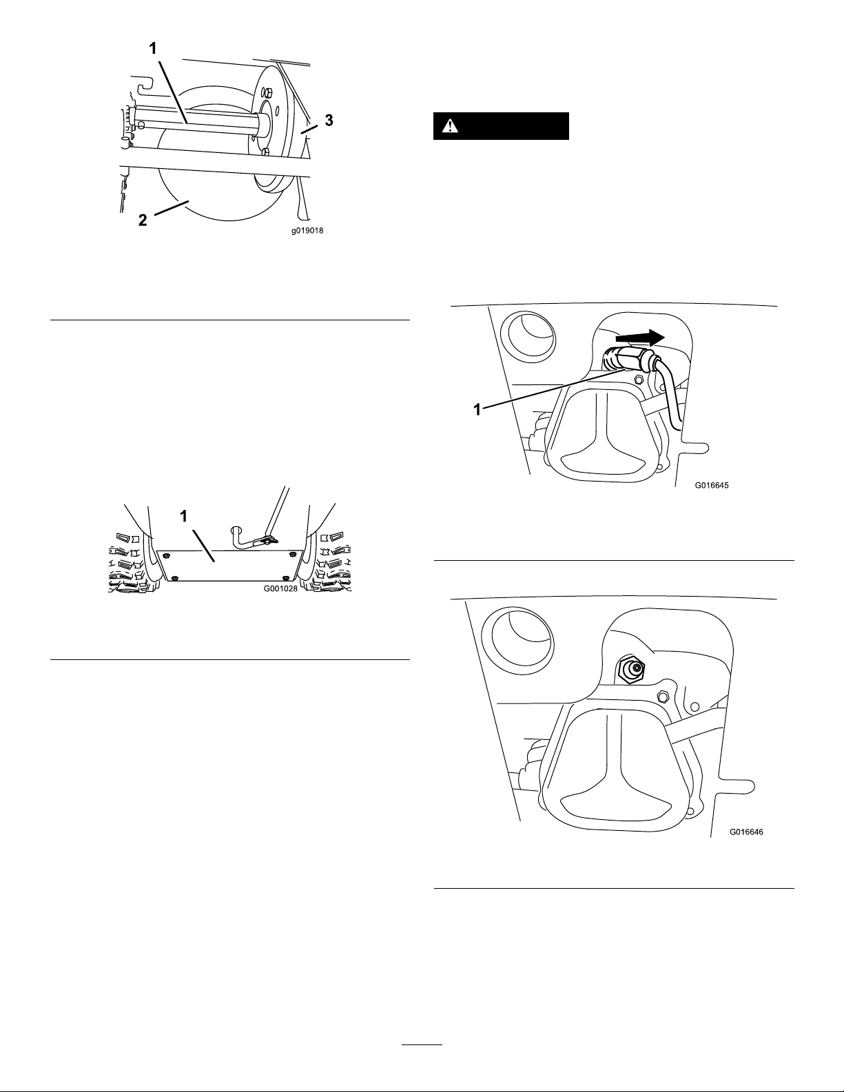
Figure41
1.Hexshaft
2.Aluminumfrictionplate
3.Rubberwheel
Important:Donotgetoilontherubberwheel
orthealuminumfrictiondriveplatebecausethe
tractiondrivewillslip(Figure41).
1.Drainthefuelfromthefueltank.
2.Tipthemachineforwardontoitsaugerhousing
andblockitsothatitcannotfall.
ReplacingtheSparkPlug
ServiceInterval:Every100hours—Replacethe
sparkplug.
WARNING
Replacingthesparkplugwhiletheengineis
hotcanresultinburns.
Waituntiltheengineiscooltoreplacethe
sparkplug.
g019018
UseaT orosparkplugorequivalent(Champion®
RN9YCorNGKBPR6ES).
1.Removetheboot(Figure43).
3.Removethebackcover(Figure42).
Figure42
1.Backcover
4.Movethespeed-selectorlevertoPositionR2.
5.Dipyourngerinautomotiveengineoiland
lightlylubricatehexshaft.
6.Movethespeed-selectorlevertoPosition6.
7.Lubricatetheotherendofthehexshaft.
8.Movethespeed-selectorleverforwardand
rearwardafewtimes.
9.Installthebackcoverandreturnthemachineto
theoperatingposition.
g016645
Figure43
1.Spark-plugboot
2.Cleanaroundthebaseofthesparkplug.
g001028
g016646
Figure44
3.Removeanddiscardtheoldsparkplug.
Note:Youwillneedaratchetwrenchextension
toremovethesparkplug.
4.Setthegapbetweentheelectrodesonanew
sparkplugat0.76mm(0.030inch)asshown
inFigure45.
23
Page 24

Figure45
1.0.76mm(0.030inch)
5.Installthenewsparkplug,tightenitrmly ,and
attachtheignitionwiretothesparkplug.
Note:Ensurethattheignitionwiresnaps
completelyintoplaceonthesparkplug.
ReplacingtheDriveBelts
Iftheauger/impellerdrivebeltorthetraction-drivebelt
becomesworn,oil-soaked,orotherwisedamaged,
haveanAuthorizedServiceDealerreplacethebelt.
g001029
24
Page 25
ReplacingtheHeadlight
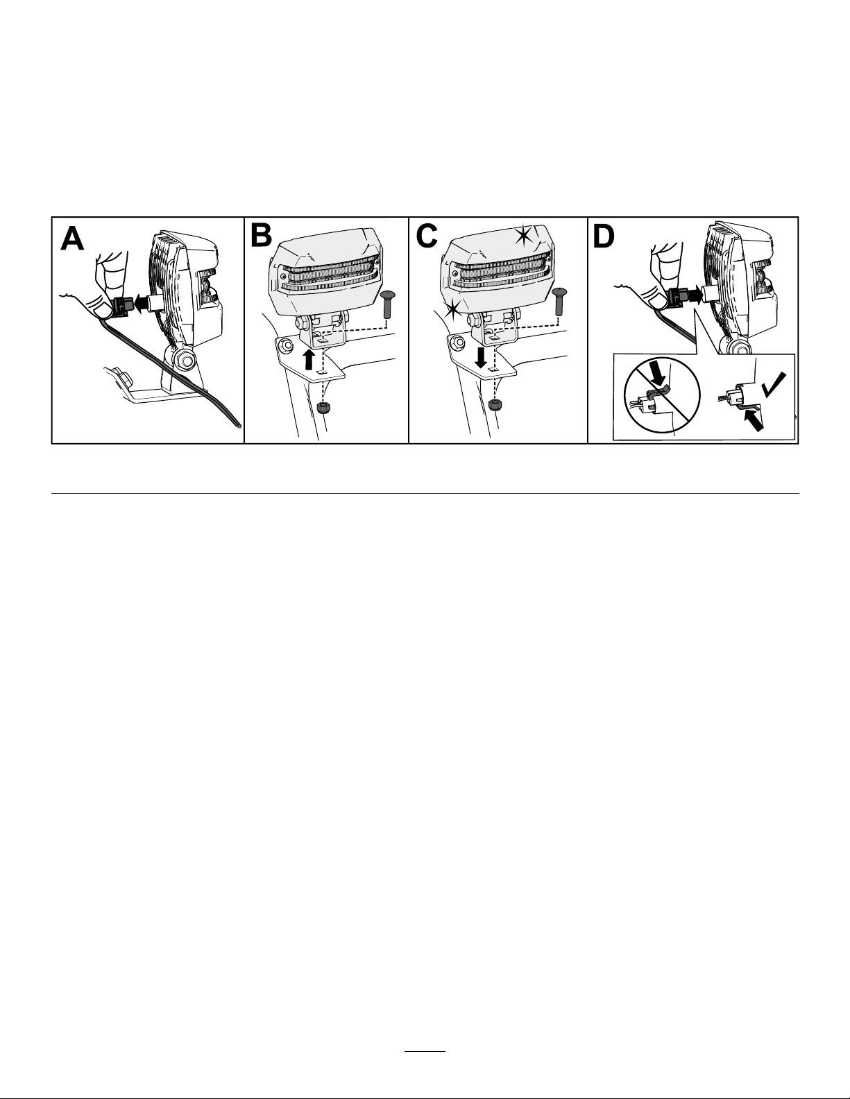
Replacetheheadlightassembly(T oropartnumber138-0670)whenneeded.
1.Removetheheadlightwirefromthebackoftheheadlight(AofFigure46).
2.Removetheboltandnutholdingtheheadlightassemblyontotheheadlightbracketandthenremovethe
oldheadlightassembly(BofFigure46).
3.Securethenewheadlightassemblyontotheheadlightbracketwiththepreviouslyremovednutand
bolt(CofFigure46).
4.Inserttheheadlightwirestraightintothebackoftheheadlightuntilitissecurelyinplace(DofFigure46).
Figure46
g256137
Storage
StorageSafety
•Shutofftheengine,removethekey ,andwait
forallmovementtostopbeforeyouleavethe
operator’sposition.Allowthemachinetocool
beforeadjusting,servicing,cleaning,orstoringit.
•Fuelfumesarehighlyammable,explosive,and
dangerousifinhaled.Ifyoustoretheproductinan
areawithanopename,thefuelfumesmayignite
andcauseanexplosion.
•Donotstorethemachineinahouse(living
area),basement,oranyotherareawhereignition
sourcesmaybepresent,suchashotwaterand
spaceheaters,clothesdryers,furnaces,andother
appliances.
•Donottipthemachineeitherforwardorbackward
withfuelinthefueltank;otherwise,fuelmayleak
outofthemachine.
•Donotstorethemachinewithitshandletipped
downontotheground;otherwise,oilmayleakinto
theenginecylinderandontotheground,andthe
enginemaynotstart.
StoringtheMachine
1.Onthelastrefuelingoftheyear,addfuel
stabilizertofreshfuelasdirectedbythefuel
stabilizermanufacturer.
Important:Donotstorefuellonger
thanthatsuggestedbythefuelstabilizer
manufacturer.
2.Runtheenginefor10minutestodistributethe
conditionedfuelthroughthefuelsystem.
3.Runthemachineuntiltheenginerunsoutoffuel.
4.Primetheengineandstartitagain.
5.Allowtheenginetorununtilitshutsoff.
Whenyoucannolongerstarttheengine,itis
sufcientlydry.
6.Allowtheenginetocool.
7.Removethekey.
8.Cleanthemachinethoroughly.
9.Touchupchippedsurfaceswithpaintavailable
fromanAuthorizedServiceDealer.Sand
affectedareasbeforepainting,andusearust
preventativetopreventthemetalpartsfrom
rusting.
10.Tightenallloosescrews,bolts,andlocknuts.
Repairorreplaceanydamagedparts.
25
Page 26

11.Coverthemachineandstoreitinaclean,dry
placeoutofthereachofchildren.
RemovingtheMachine
fromStorage
Performtheannualmaintenanceproceduresasgiven
intheRecommendedMaintenanceSchedule;referto
Maintenance(page18).
26
Page 27

Troubleshooting
Problem
Theelectricstarterdoesnotturn
(electric-startmodelsonly).
Theenginedoesnotstartorstartshard.
PossibleCauseCorrectiveAction
1.Thepowercordisdisconnectedatthe
outletorthemachine.
2.Thepowercordisworn,corroded,or
damaged.
3.Thepoweroutletisnotenergized.
1.Thekeyisnotintheignition.1.Insertthekeyintotheignition.
2.ThechokeisintheOFFpositionand
theprimerhasnotbeenpressed.
3.Thefuel-shutoffvalveisnotopen.3.Openthefuel-shutoffvalve.
4.ThethrottleisnotintheFASTposition.4.MovethethrottletotheFASTposition.
5.Thefueltankisemptyorthefuel
systemcontainsstalefuel.
6.Thespark-plugwireislooseor
disconnected.
7.Thesparkplugispitted,fouled,orthe
gapisincorrect.
8.Thefuel-ventcapisrestricted.
9.Theengine-oillevelintheengine
crankcaseistoolowortoohigh.
1.Connectthepowercordtotheoutlet
and/orthemachine.
2.Replacethepowercord.
3.Haveaqualiedelectricianenergize
theoutlet.
2.MovethechoketotheONpositionand
presstheprimer3times.
5.Drainand/orllthefueltankwith
freshfuel(notmorethan30daysold).
Iftheproblempersists,contactan
AuthorizedServiceDealer.
6.Connectthewiretothesparkplug.
7.Checkthesparkplugandadjustthe
gapifnecessary .Replacethespark
plugifitispitted,fouled,orcracked.
8.Removetheventrestrictionorreplace
thefuelcap.
9.Addordrainoiltoadjusttheoillevelin
theenginecrankcasetotheFullmark
onthedipstick.
Theenginerunsrough.
1.ThechokeisintheONposition.1.MovethechoketotheOFFposition.
2.Thefuel-shutoffvalveisnotcompletely
open.
3.Thefueltankisnearlyemptyor
containsstalefuel.
4.Thespark-plugwireisloose.
5.Thesparkplugispitted,fouled,orthe
gapisincorrect.
6.Theengine-oillevelintheengine
crankcaseistoolowortoohigh.
2.Openthefuel-shutoffvalve.
3.Drainandllthefueltankwithfresh
fuel(notmorethan30daysold).
Iftheproblempersists,contactan
AuthorizedServiceDealer.
4.Connectthewiretothesparkplug.
5.Checkthesparkplugandadjustthe
gapifnecessary .Replacethespark
plugifitispitted,fouled,orcracked.
6.Addordrainoiltoadjusttheoillevelin
theenginecrankcasetotheFullmark
onthedipstick.
27
Page 28

Problem
PossibleCauseCorrectiveAction
Theengineruns,butthemachine
dischargessnowpoorlyornotatall.
Thedischargechuteeitherdoesnotlock
intoplaceordoesnotmove.
Themachinedoesnotproperlyclearthe
snowoffthesurface.
1.ThethrottleisnotintheFASTposition
whenthrowingsnow .
2.Themachineismovingtoofasttoclear
thesnow.
3.Y ouaretryingtoremovetoomuch
snowperswath.
4.Y ouaretryingtoremoveextremely
heavyorwetsnow.
5.Thedischargechuteisplugged.5.Unclogthedischargechute.
6.Theauger/impellerdrivebeltisloose
orisoffthepulley.
7.Theauger/impellerdrivebeltisworn
orbroken.
1.Thedischarge-chutelatchisnot
properlyadjusted.
1.Theskidsand/orscraperarenot
properlyadjusted.
2.Thepressureinthetiresisnotequal.
1.MovethethrottletotheFASTposition.
2.Shiftthemachineintoalowergear.
3.Reducetheamountofsnowremoved
perswath.
4.Donotoverloadthemachinewith
extremelyheavyorwetsnow.
6.Installand/oradjusttheauger/impeller
drivebelt;refertowww.Toro.com
forservicinginformationortakethe
machinetoanAuthorizedService
Dealer.
7.Replacetheauger/impellerdrivebelt;
refertowww.Toro.comforservicing
informationortakethemachinetoan
AuthorizedServiceDealer.
1.Adjustthedischarge-chutelatch.
1.Adjusttheskidsand/orthescraper.
2.Checkandadjustthepressurein1or
bothtires.
28
Page 29

Notes:
Page 30

Notes:
Page 31

CaliforniaProposition65WarningInformation
Whatisthiswarning?
Youmayseeaproductforsalethathasawarninglabellikethefollowing:
WARNING:CancerandReproductiveHarm—www.p65Warnings.ca.gov.
WhatisProp65?
Prop65appliestoanycompanyoperatinginCalifornia,sellingproductsinCalifornia,ormanufacturingproductsthatmaybesoldinorbroughtinto
California.ItmandatesthattheGovernorofCaliforniamaintainandpublishalistofchemicalsknowntocausecancer ,birthdefects,and/orother
reproductiveharm.Thelist,whichisupdatedannually ,includeshundredsofchemicalsfoundinmanyeverydayitems.ThepurposeofProp65isto
informthepublicaboutexposuretothesechemicals.
Prop65doesnotbanthesaleofproductscontainingthesechemicalsbutinsteadrequireswarningsonanyproduct,productpackaging,orliteraturewith
theproduct.Moreover,aProp65warningdoesnotmeanthataproductisinviolationofanyproductsafetystandardsorrequirements.Infact,the
CaliforniagovernmenthasclariedthataProp65warning“isnotthesameasaregulatorydecisionthataproductis‘safe’or‘unsafe.’”Manyofthese
chemicalshavebeenusedineverydayproductsforyearswithoutdocumentedharm.Formoreinformation,gotohttps://oag.ca.gov/prop65/faqs-view-all
AProp65warningmeansthatacompanyhaseither(1)evaluatedtheexposureandhasconcludedthatitexceedsthe“nosignicantrisklevel”;or(2)
haschosentoprovideawarningbasedonitsunderstandingaboutthepresenceofalistedchemicalwithoutattemptingtoevaluatetheexposure.
Doesthislawapplyeverywhere?
Prop65warningsarerequiredunderCalifornialawonly.ThesewarningsareseenthroughoutCaliforniainawiderangeofsettings,includingbutnot
limitedtorestaurants,grocerystores,hotels,schools,andhospitals,andonawidevarietyofproducts.Additionally,someonlineandmailorder
retailersprovideProp65warningsontheirwebsitesorincatalogs.
.
HowdotheCaliforniawarningscomparetofederallimits?
Prop65standardsareoftenmorestringentthanfederalandinternationalstandards.TherearevarioussubstancesthatrequireaProp65warning
atlevelsthatarefarlowerthanfederalactionlimits.Forexample,theProp65standardforwarningsforleadis0.5μg/day,whichiswellbelow
thefederalandinternationalstandards.
Whydon’tallsimilarproductscarrythewarning?
•ProductssoldinCaliforniarequireProp65labellingwhilesimilarproductssoldelsewheredonot.
•AcompanyinvolvedinaProp65lawsuitreachingasettlementmayberequiredtouseProp65warningsforitsproducts,butothercompanies
makingsimilarproductsmayhavenosuchrequirement.
•TheenforcementofProp65isinconsistent.
•CompaniesmayelectnottoprovidewarningsbecausetheyconcludethattheyarenotrequiredtodosounderProp65;alackofwarningsfora
productdoesnotmeanthattheproductisfreeoflistedchemicalsatsimilarlevels.
WhydoesToroincludethiswarning?
Torohaschosentoprovideconsumerswithasmuchinformationaspossiblesothattheycanmakeinformeddecisionsabouttheproductstheybuyand
use.Toroprovideswarningsincertaincasesbasedonitsknowledgeofthepresenceofoneormorelistedchemicalswithoutevaluatingthelevelof
exposure,asnotallthelistedchemicalsprovideexposurelimitrequirements.WhiletheexposurefromT oroproductsmaybenegligibleorwellwithinthe
“nosignicantrisk”range,outofanabundanceofcaution,T orohaselectedtoprovidetheProp65warnings.Moreover,ifT orodoesnotprovidethese
warnings,itcouldbesuedbytheStateofCaliforniaorbyprivatepartiesseekingtoenforceProp65andsubjecttosubstantialpenalties.
RevA
Page 32

 Loading...