

Page 1
PowerMax
ModelNo.38836—SerialNo.400000000andUp
®
HeavyDuty1028OHXESnowthrower
Introduction
Thismachineisintendedtobeusedbyresidential
homeowners.Itisdesignedprimarilyforremoving
snowfrompavedsurfaces,suchasdrivewaysand
sidewalks,andothersurfacesfortrafconresidential
orcommercialproperties.Itisnotdesignedfor
removingmaterialsotherthansnow,norisitdesigned
forclearingoffgravelsurfaces.
Readthisinformationcarefullytolearnhowtooperate
andmaintainyourproductproperlyandtoavoid
injuryandproductdamage.Youareresponsiblefor
operatingtheproductproperlyandsafely.
YoumaycontactT orodirectlyatwww.T oro.com
forproductsafetyandoperationtrainingmaterials,
accessoryinformation,helpndingadealer,orto
registeryourproduct.
FormNo.3415-877RevA
Operator'sManual
Wheneveryouneedservice,genuineToroparts,or
additionalinformation,contactanAuthorizedService
DealerorToroCustomerServiceandhavethemodel
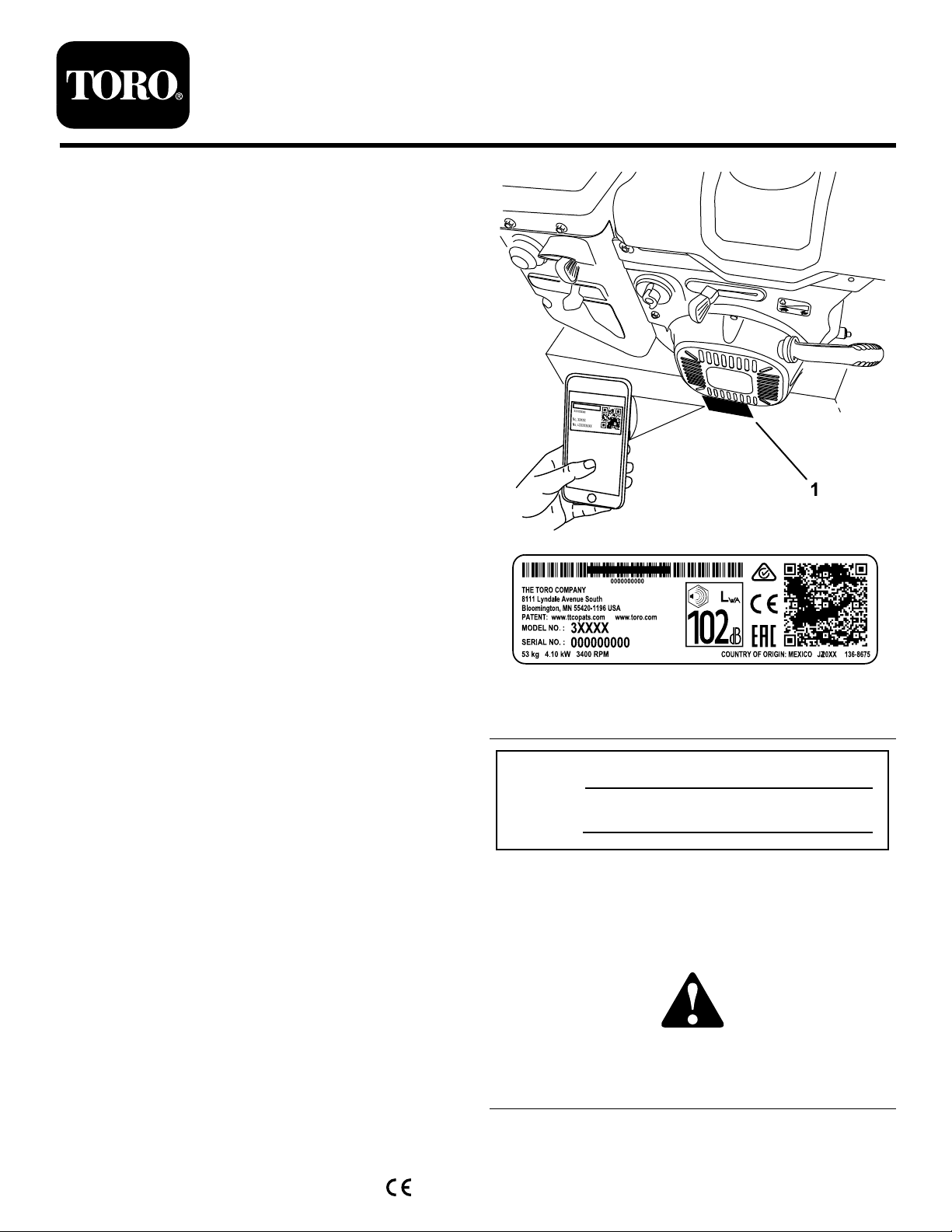
andserialnumbersofyourproductready .Figure1
identiesthelocationofthemodelandserialnumbers
ontheproduct.Writethenumbersinthespace
provided.
Important:Withyoursmartphoneortablet,scan
theQRcodeontheserialnumberdecaltoaccess
warranty,parts,andotherproductinformation.
g216798
Figure1
1.Modelandserialnumberlocation
ModelNo.
SerialNo.
Thismanualidentiespotentialhazardsandhas
safetymessagesidentiedbythesafety-alertsymbol
(Figure2),whichsignalsahazardthatmaycause
seriousinjuryordeathifyoudonotfollowthe
recommendedprecautions.
©2017—TheT oro®Company
8111LyndaleAvenueSouth
Bloomington,MN55420
Registeratwww.Toro.com.
Figure2
Safety-alertsymbol
OriginalInstructions(EN)
PrintedintheUSA
AllRightsReserved
g000502
*3415-877*A
Page 2
Thismanualuses2wordstohighlightinformation.
Importantcallsattentiontospecialmechanical
informationandNoteemphasizesgeneralinformation
worthyofspecialattention.
ThisproductcomplieswithallrelevantEuropean
directives;fordetails,pleaseseetheseparateproduct
specicDeclarationofConformity(DOC)sheet.
Important:Ifyouareusingthismachineabove
1500m(5,000ft)foracontinuousperiod,ensure
thattheHighAltitudeKithasbeeninstalled
sothattheenginemeetsCARB/EPAemission
regulations.TheHighAltitudeKitincreases
engineperformancewhilepreventingspark-plug
fouling,hardstarting,andincreasedemissions.
Onceyouhaveinstalledthekit,attachthe
high-altitudelabelnexttotheserialdecalonthe
machine.ContactanyAuthorizedToroService
DealertoobtaintheproperHighAltitudeKitand
high-altitudelabelforyourmachine.T olocate
adealerconvenienttoyou,accessourwebsite
atwww.Toro.comorcontactourToroCustomer
CareDepartmentatthenumber(s)listedinyour
EmissionControlWarrantyStatement.Remove
thekitfromtheengineandrestoretheengineto
itsoriginalfactorycongurationwhenrunningthe
engineunder1500m(5,000ft).Donotoperatean
enginethathasbeenconvertedforhigh-altitude
useatloweraltitudes;otherwise,youcould
overheatanddamagetheengine.
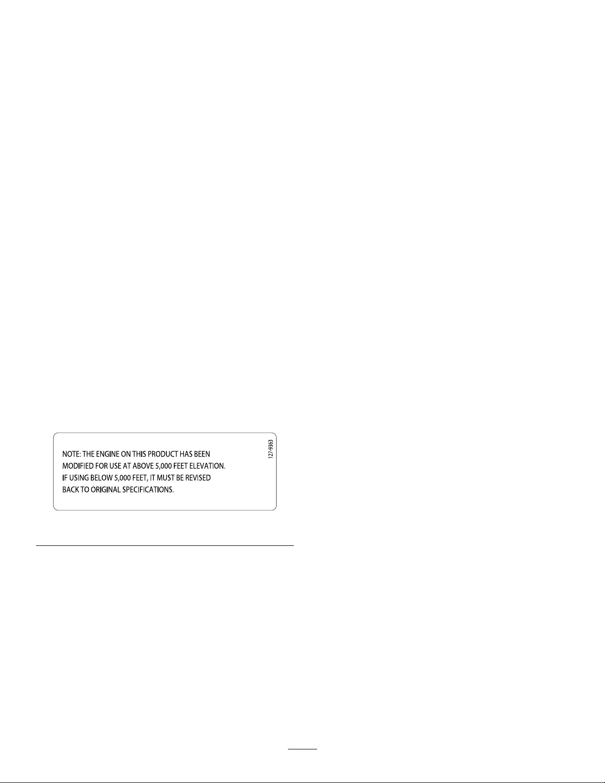
Ifyouareunsurewhetherornotyourmachinehas
beenconvertedforhigh-altitudeuse,lookforthe
followinglabel(Figure3).
Figure3
Contents
5ConnectingtheHeadlightandHandwarmer
WiretotheEngine.........................................10
6CheckingtheEngine-OilLevel.......................10
7CheckingtheTirePressure.............................11
8CheckingtheSkidsandScraper.....................11
9CheckingtheOperationoftheTraction
Drive..............................................................11
ProductOverview...................................................12
Operation................................................................13
BeforeOperation.................................................13
BeforeOperationSafety...................................13
FillingtheFuelT ank..........................................13
DuringOperation.................................................14
DuringOperationSafety...................................14
StartingtheEngine...........................................14
ShuttingOfftheEngine.....................................16
OperatingtheHandwarmers.............................17
OperatingtheTractionDrive.............................17
UsingtheWheel-ClutchLevers.........................17
OperatingtheSpeedSelector...........................18
OperatingtheAuger/ImpellerDrive...................18
OperatingtheQuickStick®...............................18
ClearingaCloggedDischargeChute................19
OperatingTips.................................................20
AfterOperation....................................................20
AfterOperationSafety......................................20
PreventingFreeze-upafterUse........................20
Maintenance...........................................................21
RecommendedMaintenanceSchedule(s)...........21
MaintenanceSafety..........................................21
PreparingforMaintenance...............................21
CheckingtheEngine-OilLevel..........................22
CheckingandAdjustingtheSkidsand
Scraper.........................................................22
CheckingandAdjustingtheTraction
Cable............................................................23
CheckingandAdjustingtheAuger/Impeller
Cable............................................................23
CheckingtheAuger-Gearbox-OilLevel.............24
ChangingtheEngineOil...................................25
decal127-9363
ReplacingtheSparkPlug.................................25
AdjustingtheDischarge-ChuteLatch................26
ReplacingtheDriveBelts..................................27
ReplacingtheHeadlightBulb............................27
Storage...................................................................28
PreparingtheMachineforStorage...................28
RemovingtheMachinefromStorage................28
Troubleshooting......................................................29
Introduction...............................................................1
Safety.......................................................................3
GeneralSafety...................................................3
SafetyandInstructionalDecals..........................4
Setup........................................................................6
1InstallingtheUpperHandle..............................7
2InstallingtheWheel-Clutch-Cable
Ends................................................................7
3InstallingtheTraction-ControlLinkage.............8
4InstallingtheChute-ControlRod......................9
2
Page 3

Safety
GeneralSafety
ThismachinecomplieswithANSIB71.3specications.
•Readandunderstandthecontentsofthis
Operator’sManualbeforeyoustarttheengine.
Ensurethateveryoneusingthisproductknows
howtousetheproductandunderstandsthe
warnings.
•Donotputyourhandsorfeetnearmoving
componentsonthemachine.
•Donotoperatethemachinewithoutallguards
andothersafetyprotectivedevicesinplaceand
workingonthemachine.
•Keepclearofanydischargeopening.Keep
bystanderssafedistanceawayfromthemachine.
•Keepchildrenoutoftheoperatingarea.Never
allowchildrentooperatethemachine.
•Shutofftheenginebeforeunclogging,servicing,
orfuelingthemachine.
Youcanndadditionalitemsofsafetyinformationin
theirrespectivesectionsthroughoutthismanual.
3
Page 4
SafetyandInstructionalDecals
x 3
1
2
3
4
5
120-9805
Safetydecalsandinstructionsareeasilyvisibletotheoperatorandarelocatednearanyarea
ofpotentialdanger.Replaceanydecalthatisdamagedormissing.
decal112-6625
112-6625
OrderPartNo.112-6629
1.Cutting/dismembermenthazard,impeller—donotplace
yourhandinthechute;shutofftheenginebeforeleaving
theoperator'spositionanduseatooltoclearthechute.
decal106-4525
106-4525
OrderPartNo.112-6633
1.Fast
2.Forwardspeeds4.Reversespeeds
3.Slow
decal120-9805
120-9805
decal107-3040
107-3040
1.Cutting/dismembermenthazardsofhandorfoot,impeller
andauger—keepbystandersasafedistanceawayfrom
themachine.
1.Insertthekey.
2.Primetheengine3times.
3.Engagethechoke.
4.Pullthestartercord.
5.Oncetheengineisrunning,disengagethechoke.
4
Page 5
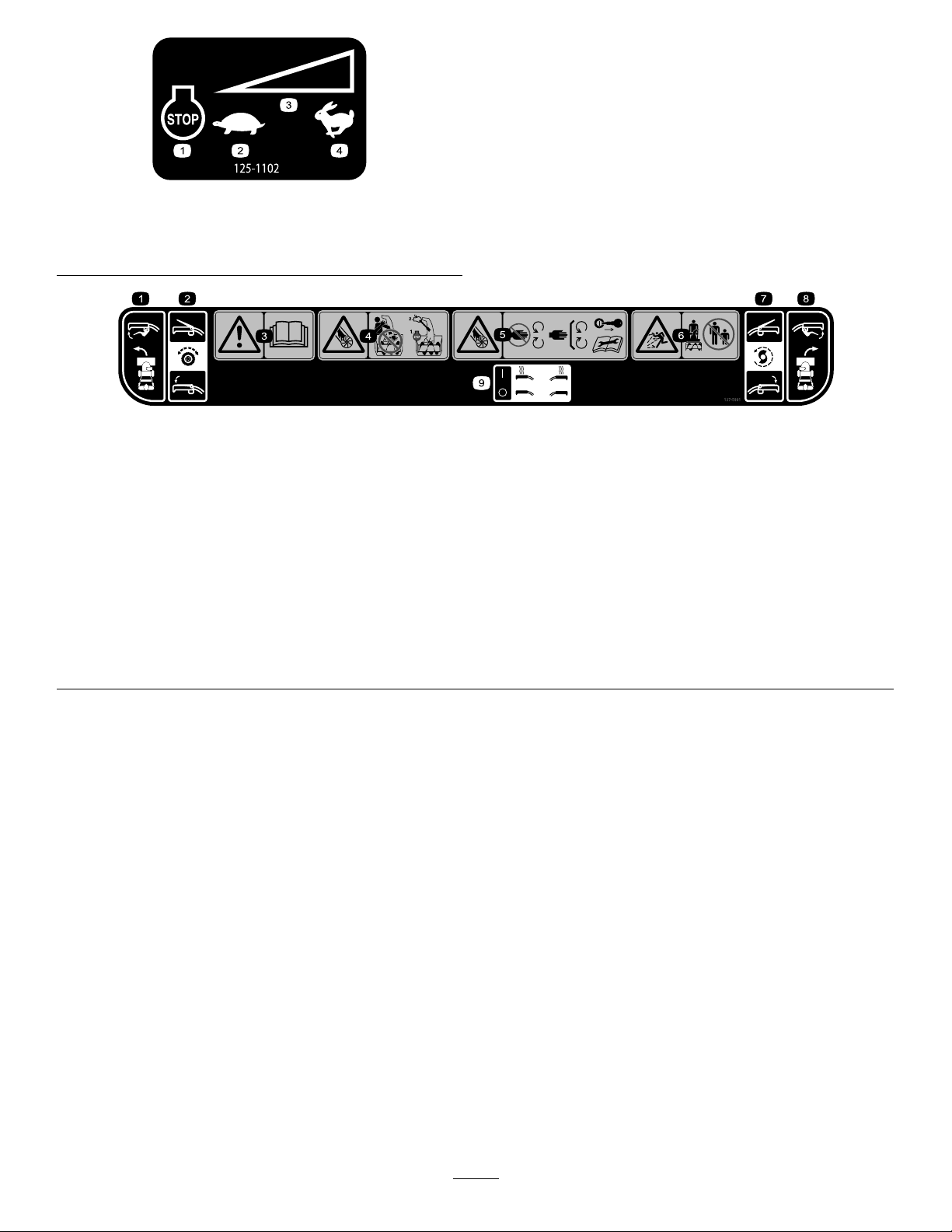
125-1102
decal125-1102
1.Engine—shutoff
2.Slow
3.Variablespeedcontrol
4.Fast
127–5991
1.Leftturncontrol4.Cutting/dismembermenthazard,
2.Tractiondrive—squeezetheleverto
engage;releasethelevertodisengage.
3.Warning—readtheOperator'sManual.
impeller—donotplaceyourhandin
thechute;shutofftheenginebefore
leavingtheoperator'spositionanduse
atooltoclearthechute.
5.Cutting/dismembermenthazard,
impeller—stayawayfrommoving
parts;keepallguardsandshieldsin
place;removetheignitionkeyand
readtheinstructionsbeforeservicing
orperformingmaintenance.
6.Thrownobjecthazard—keep
bystandersasafedistancefromthe
machine.
decal127-5991
7.Auger/impellerdrive—squeezethe
levertoengage;releasetheleverto
disengage.
8.Rightturncontrol
9.Handwarmercontrols
5
Page 6

Setup
LooseParts
Usethechartbelowtoverifythatallpartshavebeenshipped.
ProcedureDescription
1
2
3
4
5
6
7
8
9
Handlebolt4
Curvedwasher
Locknut4
Nopartsrequired
Nopartsrequired
Carriagebolt
Locknut2
Nopartsrequired
Nopartsrequired
Nopartsrequired
Nopartsrequired
Nopartsrequired
Qty.
Use
4
–
–
2
–
–
–
–
–
Installtheupperhandle.
Installthewheel-clutch-cableends.
Installthetraction-controllinkage.
Installthechute-controlrod.
Connecttheheadlightandhandwarmer
wiretotheengine.
Checktheengine-oillevel.
Checkthetirepressure.
Checktheskidsandscraper.
Checktheoperationofthetractiondrive.
6
Page 7
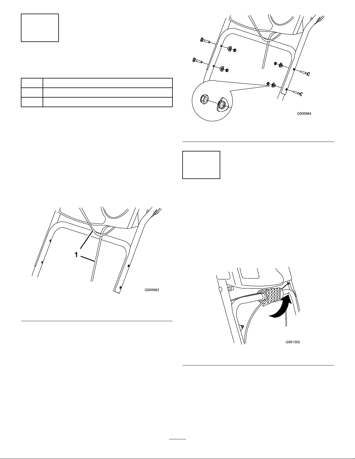
1
InstallingtheUpperHandle
Partsneededforthisprocedure:
4Handlebolt
4
Curvedwasher
4Locknut
Procedure
Note:Donotremovetherubberbandonthecables
untilyouhaveinstalledtheupperhandle.
1.Liftandrotatetheupperhandleandpositionit
overthelowerhandle(Figure4).
Important:Routethecablesattachedtothe
QuickStick
andensurethatthecablesandthewirefor
theheadlightarenotpinchedbetweenthe
handlesections.
®
insidetheupperhandlelegs
g000984
Figure5
2
Installingthe Wheel-Clutch-CableEnds
NoPartsRequired
Procedure
1.Unwrapthebubblewrapfromthecablesonthe
lowerhandle(Figure6).
Figure4
1.Cables
2.Securetheupperhandlewith4handlebolts,
4curvedwashers,and4locknutsfromthe
loose-partsbag(Figure5).
g000983
g001302
Figure6
2.Routeeithertheleftorrightcableendoverthe
lowerhandleandinsertthecableendintothe
holeinthecorrespondingwheel-clutchlever
(Figure7).
7
Page 8
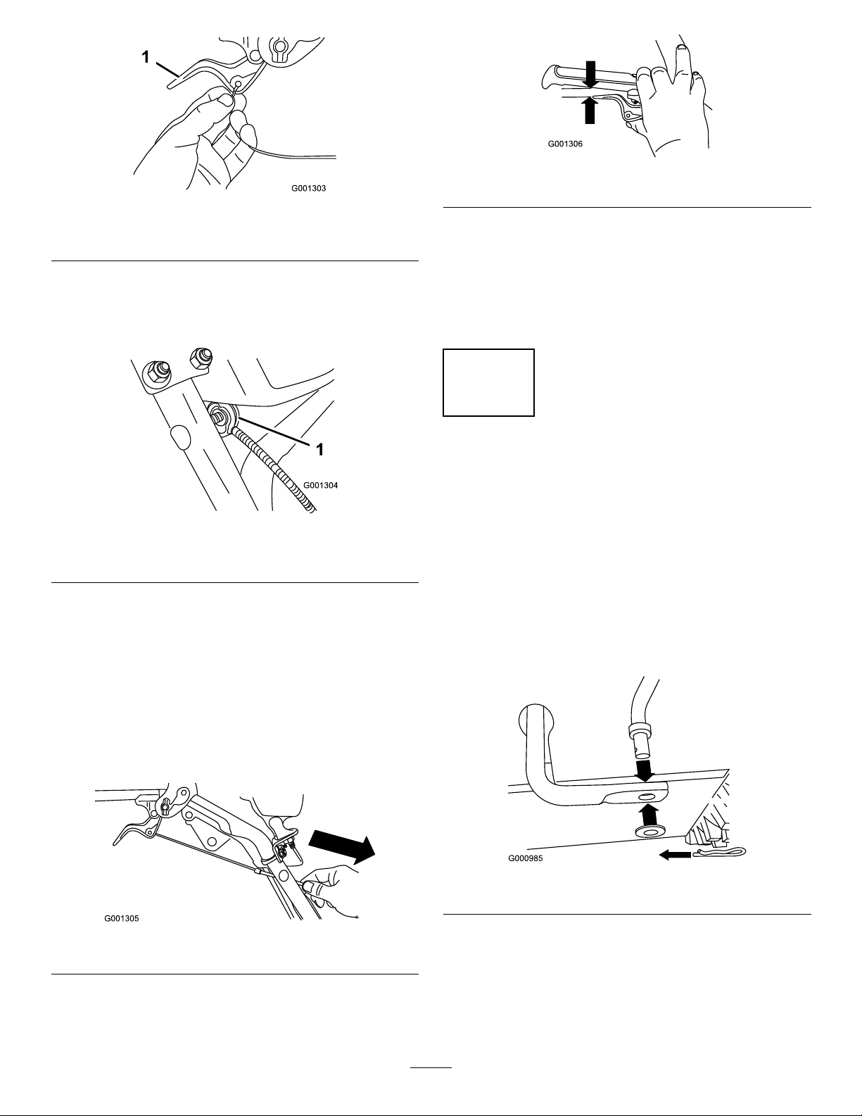
Figure7
1.Wheel-clutchlever
3.Removethenutandwasherfromthehandle,
attachthecableclamponthecabletothe
handle,installthewasherandthenut,and
tightenthenutbyhand(Figure8).
g001306
Figure10
g001303
Note:Thegapshouldbeapproximatelythe
thicknessofapencil(1/4inchor6mm).Ifitis
greater,loosenthecable-clampnut,slidethe
cablejacketupslightly,tightenthecable-clamp
nut,andcheckthegapagain.
6.Repeatsteps2through5fortheothercable.
3
Installingthe Traction-ControlLinkage
Figure8
1.Cableclamp(2)
Important:Ensurethatthecurvedsideof
thecableclampisagainstthehandleand
thatthecableisroutedbelowtheclampbolt.
Thecablemustbeinastraightlinefromthe
cableclamptothepointwhereitattachesto
thewheel-clutchlever.
4.Pullthecablejacketdowngentlyuntilthe
wheel-clutchleverisdownandtheslackisout
ofthecable,thentightenthecable-clampnut
securely(Figure9).
g001304
NoPartsRequired
Procedure
1.Removethehairpincotterandwasherfromthe
lowerendofthespeed-controlrodandinsertthe
lowerendoftherodintothelowerlinkarmso
thatthebentendofthespeed-controlrodfaces
rearward(Figure11).
g000985
Figure11
Figure9
5.Squeezetheleverfully ,thencheckthegap
betweenthebottomofthehandleandtheend
ofthewheel-clutchlever(Figure10).
g001305
2.Securethelowerendofthespeed-controlrod
withthewasherandhairpincotterthatyou
previouslyremoved.
3.Removethehairpincotterandouterwasher
fromthetrunnionontheupperendofthe
speed-controlrod(Figure12).
8
Page 9
Note:Foreasierinstallation,lookdownthrough
theopeninginthespeedselector(Figure14).
Figure12
1.Speed-selectorlever
2.Trunnion
3.Innerwasher
4.Outerwasher
Note:Foreasierinstallation,leavetheat
washeronthetrunnion(Figure12).
4.Shiftthespeed-selectorleverintoR2position.
5.Rotatethelowerlinkarmfullyupward
(counterclockwise)(Figure13).
Figure13
g006528
Figure14
1.Speedselector
g006527
4
InstallingtheChute-Control Rod
Partsneededforthisprocedure:
2
Carriagebolt
2Locknut
g000987
Procedure
1.UnwraptheQuickStick®androtateitsothatit
isuprightandinthecenter.
6.Liftuponthespeed-controlrodandinsertthe
trunnionintotheholeinthespeed-selectorlever
(Figure12).
Note:Ifthetrunniondoesnottintothehole
whenyouliftuponthespeed-controlrod,
rotatethetrunnionupwardordownwardonthe
speed-controlroduntilitts.
7.Securethetrunnionandupperendofthe
speed-controlrodwiththeouterwasherand
hairpincotterthatyoupreviouslyremoved.
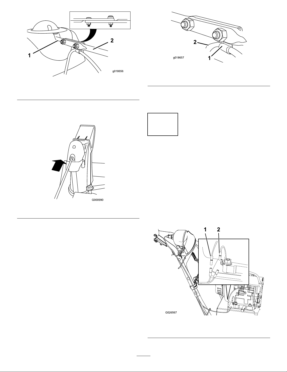
2.Holdthebluetriggercapdownandpullthelever
fullyrearward.
Note:Thedischargechuteanddeectorshould
faceforward.Iftheydonot,holdthebluetrigger
capdown(butdonotmovetheQuickStick)and
rotatethedischargechuteuntiltheydo.
3.Aligntheattenedbackendofthelong
chute-controlrodwiththeattenedfrontendof
theshortrodthatextendsfromthecontrolpanel
sothattheynesttogether(Figure15).
9
Page 10
g018656
g018657
Figure17
g018657
Figure15
1.Shortrod
4.Insertthefrontendoftherodintotheopening
inthebackofthechute-gearcoveruntilitslides
intothechutegear(Figure16).
2.Longchute-controlrod
Figure16
g018656
1.Cableclip2.Deectorcable
7.Holdthebluetriggercapdownandrotatethe
QuickStickinacircletoensurethatthechute
anddeectoroperatesmoothly .
5
ConnectingtheHeadlight andHandwarmerWireto theEngine
NoPartsRequired
Procedure
g000990
Plugaconnectorintothestarterwireandanotherinto
theground(Figure18).
5.Aligntheholesinthenestedendsoftherods
andinsert2carriagebolts(fromtheloose-parts
bag)throughtheshortrodfromtheleftsideof
themachine(fromtheoperatingposition).
6.Insertthecableclipthatsupportsthedeector
cableontotheforwardcarriagebolt,andsecure
thecarriageboltswiththelocknutsfromthe
loose-partsbag(Figure17).
Note:Thepigtailsarecolor-coded.
g026567
Figure18
1.Starter-wireconnector2.Groundconnector
10
Page 11

6
9
CheckingtheEngine-Oil
Level
NoPartsRequired
Procedure
Note:Yourmachinecomeswithoilintheengine
crankcase.Beforestartingtheengine,checktheoil
levelandaddoilifnecessary.
RefertoCheckingtheEngine-OilLevel(page22).
7
CheckingtheTirePressure
NoPartsRequired
Procedure
Thetiresareoverinatedatthefactoryforshipping.
Reducethepressureequallyinbothtirestobetween
116and137kPa(17and20psi).
CheckingtheOperationof theTractionDrive
NoPartsRequired
Procedure
CAUTION
Ifthetractiondriveisnotproperlyadjusted,
themachinemaymoveinthedirection
oppositeofwhatyouintended,causinginjury
and/orpropertydamage.
Carefullycheckthetractiondriveandadjustit
properly,ifnecessary.
Note:Tochecktheoperationofthetractiondrive,you
mustengagetheself-propelfeaturebypinningthe
wheelsintheaxle;referto9CheckingtheOperation
oftheTractionDrive(page11).
1.Starttheengine;refertoStartingtheEngine
(page14).
2.MovethespeedselectortoPositionR1;referto
OperatingtheSpeedSelector(page18).
3.Squeezetheleft(traction)levertothehandgrip
(Figure19).
8
CheckingtheSkidsand Scraper
NoPartsRequired
Procedure
RefertoCheckingandAdjustingtheSkidsand
Scraper(page22).
g001011
Figure19
Themachineshouldmoverearward.Ifthe
machinedoesnotmoveormovesforward,
completethefollowing:
A.Releasethetractionleverandshutoffthe
engine.
B.Disconnectthetrunnionfromthe
speed-selectorlever(Figure12).
C.Turnthetrunniondownward(clockwise)on
thespeed-controlrod(Figure12).
11
Page 12
D.Connectthetrunniontothespeed-selector
G016495
ST
OP
1
2
3
4
5
6
7
G016500
lever(Figure12).
4.Releasethetractionlever.
5.MovethespeedselectortoPosition1;referto
OperatingtheSpeedSelector(page18).
6.Squeezetheleft(traction)levertothehandgrip
(Figure19).
Themachineshouldmoveforward.Ifthe
machinedoesnotmoveormovesrearward,
completethefollowing:
A.Releasethetractionleverandshutoffthe
engine.
B.Disconnectthetrunnionfromthe
speed-selectorlever(Figure12).
C.Turnthetrunnionupward(counterclockwise)
onthespeed-controlrod(Figure12).
D.Connectthetrunniontothespeed-selector
lever(Figure12).
7.Ifyoumadeanyadjustments,repeatthis
procedureuntilnoadjustmentsarerequired.
Important:Ifthemachinemoveswhenthe
tractionleverisinthereleasedposition,checkthe
tractioncable;refertoCheckingandAdjusting
theTractionCable(page23)ortakethemachine
toanAuthorizedServiceDealerforservice.
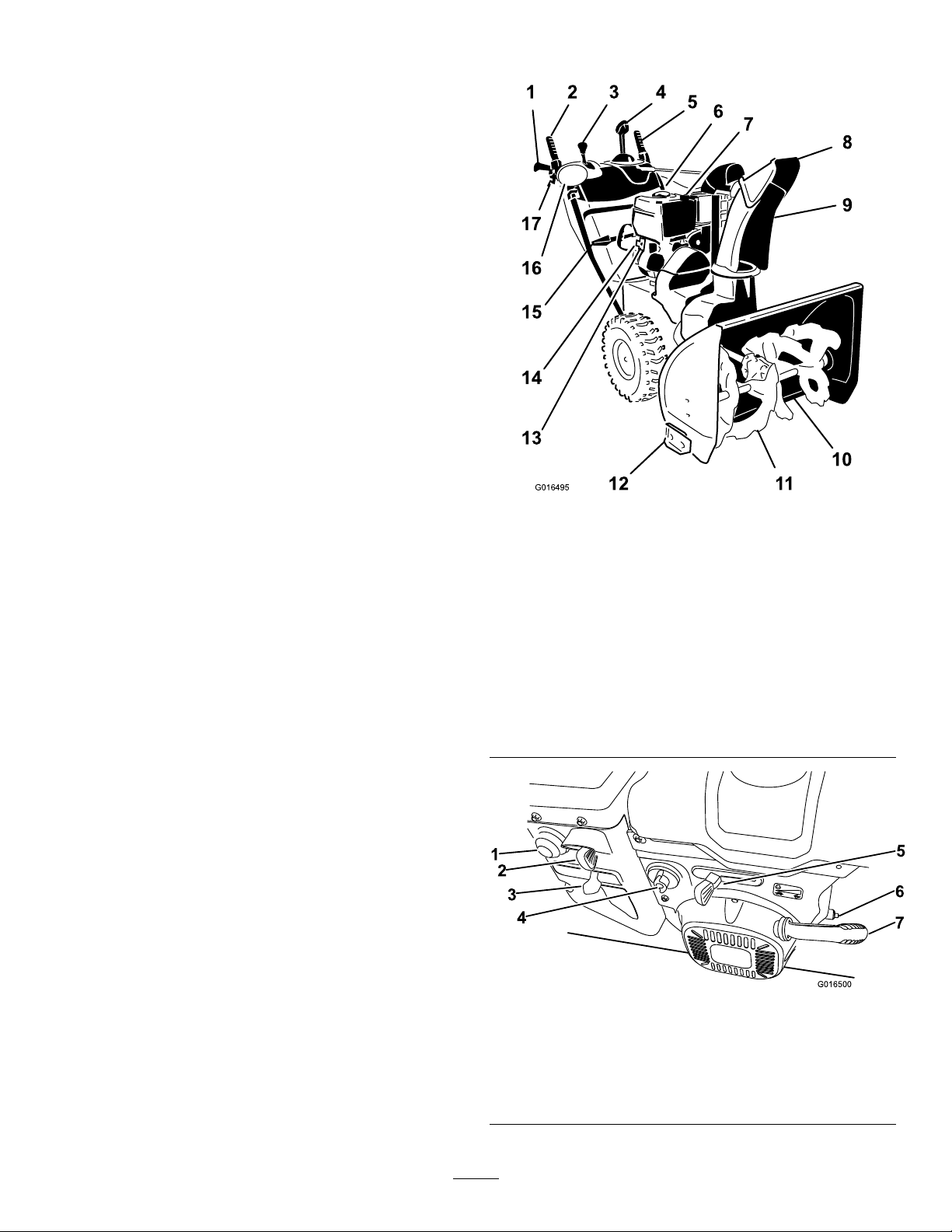
ProductOverview
Figure20
1.Hand-grip(2)10.Scraper
2.Auger/impellerlever
3.Speed-selectorlever12.Skid(2)
4.QuickStick®discharge
chutecontrol
5.Tractionlever14.Electric-starterplug-in
6.Fuel-tankcap
7.Oil-lltube/dipstick
8.Chutedeector17.Wheel-clutchlever(2)
9.Dischargechute
11.Auger
13.Electric-startbutton
15.Snow-cleanouttool
16.Headlight
g016495
g016500
Figure21
1.Primer5.Throttle
2.Ignitionswitch
3.Choke
4.Fuel-shutoffvalve
6.Oil-drainplug
7.Recoil-starthandle
12
Page 13
Figure22
1.Snow-cleanouttool(attachedtothehandle)
DANGER
Fuelisextremelyammableandexplosive.A
reorexplosionfromfuelcanburnyouand
g004217
others.
•Topreventastaticchargefromignitingthe
fuel,placethecontainerand/ormachineon
thegroundbeforelling,notinavehicle
oronanobject.
Operation
Note:Determinetheleftandrightsidesofthe
machinefromthenormaloperatingposition.
BeforeOperation
BeforeOperationSafety
•Forelectric-startmodelsonly:Useextension
cordsandreceptaclesasspeciedinthemanual.
Thoroughlyinspecttheelectricalcordbefore
pluggingitintoapowersource.Ifthecordis
damaged,donotuseit.Replacethedamaged
cord.Unplugthepowercordwheneveryouare
notstartingthemachine.
•Wearadequatewintergarmentswhenever
youoperatethemachine.Wearsubstantial,
slip-resistantfootwearthatimprovesfootingon
slipperysurfaces.Avoidloose-ttingclothingthat
cangetcaughtinmovingparts.
•Alwaysweareyeprotectionduringoperationor
whileperforminganadjustmentorrepairtoprotect
youreyesfromforeignobjectsthatthemachine
maythrow.
•Thoroughlyinspecttheareawhereyouwillusethe
machine,andremovealldoormats,sleds,boards,
wires,andotherforeignobjects.
•Ifashield,safetydevice,ordecalisdamaged,
illegible,ormissing,repairorreplaceitbefore
beginningoperation.Also,tightenanyloose
fasteners.
•Fillthetankoutdoorswhentheengineis
cold.Wipeupspills.
•Donothandlefuelwhensmokingor
aroundanopenameorsparks.
•Storefuelinanapprovedfuelcontainer,
outofthereachofchildren.
•Donottipthemachineeitherforward
orbackwardwithfuelinthefueltank;
otherwise,fuelmayleakoutofthe
machine.
FillingtheFuelTank
•Forbestresults,useonlyclean,fresh(lessthan
30daysold),unleadedgasolinewithanoctane
ratingof87orhigher((R+M)/2ratingmethod).
•Oxygenatedfuelwithupto10%ethanolor15%
MTBEbyvolumeisacceptable.
•Donotuseethanolblendsofgasoline(such
asE15orE85)withmorethan10%ethanolby
volume.Performanceproblemsand/orengine
damagemayresultwhichmaynotbecovered
underwarranty.
•Donotusegasolinecontainingmethanol.
•Donotstorefueleitherinthefueltankorfuel
containersoverthewinterunlessyouuseafuel
stabilizer.
•Donotaddoiltogasoline.
Donotllabovethebottomofthefueltank(Figure
23).
13
Page 14

Figure23
G016512
•Exerciseextremecautionwhenoperatingonor
crossinggraveldrives,walks,orroads.Stayalert
forhiddenhazardsortrafc.
•Neverattempttomakeanyadjustmentswhilethe
engineisrunning.
•Afterstrikingaforeignobject,shutofftheengine,
removetheignitionkey(electric-startmodels
only),thoroughlyinspectthemachineforany
damage,andrepairthedamagebeforestarting
andoperatingthemachine.
•Ifthemachineshouldstarttovibrateabnormally,
shutofftheengineandcheckforthecause.
•Donotruntheengineindoorsunlessthereis
adequateventilation(e.g.,leavingtheoutsidedoor
g215907
open);exhaustfumesaredangerous.
•Donotoverloadthemachinecapacityby
attemptingtoclearsnowattoofastarate.
Note:Forbestresults,purchaseonlythequantity
offuelthatyouexpecttousein30days.Otherwise,
youmayaddfuelstabilizertonewlypurchasedfuelto
keepitfreshforupto6months.
DuringOperation
DuringOperationSafety
•Shutofftheenginebeforeuncloggingthe
machineandalwaysuseastickorthe
snow-cleanouttool(ifprovided).
•Arotatingaugercaninjurehandsorfeet.Stay
behindthehandlesandawayfromthedischarge
openingwhileoperatingthemachine.Keepyour
face,hands,feet,andanyotherpartofyour
bodyorclothingawayfrommovingorrotating
parts.
•Neverdirectthedischargetowardpeopleorareas
wherepropertydamagecanoccur.
•Exercisecautiontoavoidslippingorfalling.
Alwaysbesureofyourfooting,andkeeparm
holdonthehandles.Walk;neverrun.
•Nevertouchahotengineormufer.
StartingtheEngine
1.Checktheengine-oillevel.RefertoChecking
theEngine-OilLevel(page22).
2.Turnthefuel-shutoffvalve1/4turn
counterclockwisetoopenit(Figure24).
•Exerciseextremecautionwhenoperatingon
slopes.
•Neveroperatethemachinewithoutgoodvisibility
orlight.
•Donotoperatethemachinewhileill,tired,or
undertheinuenceofalcoholordrugs.
•Lookbehindandusecarewhenbackingupwith
themachine.
•Whennotactivelyclearingsnow,disengagepower
totheauger.
g016512
Figure24
3.Fullyinserttheignitionkey(Figure25).
14
Page 15

1
G016498
Figure25
g037221
G016501
STOP
G016504
1.Ignitionkey
4.Firmlypushintheprimerwithyourthumbas
indicatedbythefollowingtable,holdingthe
primerinforasecondbeforereleasingiteach
time(Figure26).
5.MovethechoketotheCHOKEposition(Figure
27).
g016498
g016501
Figure27
Temperature
Above-18°C(0°F)
-23°Cto-18°C(-10°Fto0°F)
Below-23°C(-10°F)
Figure26
SuggestedNumberof
Primes
3
4
6
6.MovethethrottletotheFASTposition(Figure
28).
g016504
Figure28
g037221
7.Startthemachinebypullingtherecoilstarteror
pressingtheelectric-starterbutton(Figure29).
15
Page 16

Figure29
STOP
G016505
G016499
1.Electric-starterbutton3.Recoil-starthandle
2.Electricstarterplug-in
Note:T ousetheelectricstarter(electric-start
modelsonly),connectapowercordtothe
plug-inrstandthentoapoweroutlet.Use
onlyaUL-listed,16-gaugeextensioncord
recommendedforoutdoorusethatisnotlonger
than50feet(15m).
WARNING
Theelectricalcordcanbecomedamaged,
causingashockorre.
Thoroughlyinspecttheelectricalcord
beforeusingthemachine.Ifthecord
isdamaged,donotuseit.Replaceor
repairthedamagedcordimmediately.
ContactanAuthorizedServiceDealerfor
assistance.
ShuttingOfftheEngine
1.MovethethrottletotheSLOWposition,andthen
totheSTOPposition(Figure30).Y oucanalso
shutofftheenginebypullingtheignitionkey
outwardtothemiddleposition.
g215361
g016505
Figure30
2.Waitforallmovingpartstostopbeforeleaving
theoperatingposition.
3.Removetheignitionkeytopreventaccidental
starting.
4.Closethefuelshutoffvalvebyrotatingit
clockwise(Figure31).
Important:T opreventdamagingtheelectric
starter,runitinshortcycles(5secondson,
5secondsoff),nomorethan10times.Ifthe
enginestilldoesnotstart,takethemachine
toanAuthorizedServiceDealerforservice.
8.Disconnectthepowercordfromthepoweroutlet
rstandthenfromthemachine(electric-start
modelsonly).
9.Allowtheenginetowarmup;graduallymove
thechoketowardtheRunposition.Waitfor
theenginetorunsmoothlybeforeeachchoke
adjustment.
CAUTION
Ifyouleavethemachinepluggedintoa
poweroutlet,someonecaninadvertently
startthemachineandinjurepeopleor
damageproperty.
Unplugthepowercordwheneveryouare
notstartingthemachine.
g016499
Figure31
5.Pulltherecoilstarter3or4times.
Note:Thishelpspreventtherecoilstarterfrom
freezingup.
16
Page 17

Operatingthe Handwarmers
Operatethehandwarmersasfollows:
•PresstheswitchtotheONpositiontoturnonthe
handwarmers.
•PresstheswitchtotheOFFpositiontoturnoffthe
handwarmers.
Figure32
1.On/Offswitch3.OFFposition
2.ONposition
g001011
Figure33
2.Tostopthetractiondrive,releasethetraction
lever.
UsingtheWheel-Clutch Levers
Thewheel-clutchleversallowyoutomomentarily
disengagethedriveto1orbothwheelswiththe
traction-driveleverstillengaged.Thisenablesyouto
g026460
turnandmaneuverthemachineeasily.
Note:Holdingdownthetractionleveragainstthe
handleengagesthetractiondrivetobothwheels.
Toturnthemachinetotheright,liftuptheright
wheel-clutchleverandsqueezeittowardthehandle
(Figure34).
OperatingtheTraction Drive
CAUTION
Ifthetractiondriveisnotproperlyadjusted,
themachinemaymoveinthedirection
oppositeofwhatyouintended,causinginjury
and/orpropertydamage.
Carefullycheckthetractiondriveandadjust
itproperly,ifnecessary;refertoChecking
andAdjustingtheTractionCable(page23)for
moreinformation.
Important:Ifthemachinemoveswhenthe
tractionleverisinthereleasedposition,checkthe
tractioncable;refertoCheckingandAdjusting
theTractionCable(page23)ortakethemachine
toanAuthorizedServiceDealerforservice.
Important:Tooperatethetractiondrive,you
mustoperatethemachinewiththeself-propel
featureengaged.Referto9Checkingthe
OperationoftheTractionDrive(page11).
g001307
Figure34
Note:Thisdisengagesthedrivetotherightwheel
whiletheleftwheelcontinuesdriving,andthemachine
turnstotheright.
Note:Similarly,squeezingtheleftwheel-clutchlever
turnsthemachinetotheleft.
Whenyoucompletetheturn,releasethewheel-clutch
lever,andthedrivere-engagesbothwheels(Figure
35).
1.Toengagethetractiondrive,squeezetheleft
(traction)levertothehandgrip(Figure33).
17
Page 18

Figure35
Momentarilysqueezingandreleasingtheleftorright
wheel-clutchleveralsoallowsforsteeringadjustments
tokeepthemachinegoinginastraightline,especially
indeepsnow.
Squeezingbothwheel-clutchleverssimultaneously
disengagesthedrivetobothwheels.Thisenables
youtomanuallymovethemachinebackwardwithout
stoppingtoshiftitintoareversegear.Italsoallows
youtomaneuverandtransportthemachinemore
easilywhentheengineisnotrunning.
OperatingtheSpeed Selector
Thespeedselectorhas6forwardand2reverse
gears.T ochangespeeds,releasethetractionlever
andshiftthespeed-selectorlevertothedesired
position(Figure36).Theleverlocksinanotchat
eachspeedselection.
Operatingthe Auger/ImpellerDrive
1.Toengagetheauger/impellerdrive,squeeze
theright(auger/impeller)levertothehandgrip
(Figure37).
g001308
g001013
Figure37
2.Tostoptheaugerandimpeller,releasetheright
lever.
Important:Whenyouengageboththe
auger/impellerleverandthetractionlever,
thetractionleverlockstheauger/impeller
leverdown,freeingyourrighthand.To
releasebothlevers,simplyreleasetheleft
(traction)lever.
3.Iftheaugerandimpellercontinuetorotatewhen
youreleasetheauger/impellerlever,donot
operatethemachine.Checktheauger/impeller
cable;refertoCheckingandAdjustingthe
Auger/ImpellerCable(page23)andadjustitif
necessary.Otherwise,takethemachinetoan
AuthorizedDealerforservice.
Figure36
WARNING
Iftheaugerandimpellercontinue
torotatewhenyoureleasethe
auger/impellerlever,youcouldseriously
g001012
injureyourselforothers.
Donotoperatethemachine.Takeittoan
AuthorizedServiceDealerforservice.
OperatingtheQuickStick®
HoldthebluetriggercapdowntousetheQuickStick
tomovethedischargechuteandthechutedeector.
Releasethetriggercaptolockthedischargechute
andchutedeectorintoposition(Figure38).
18
Page 19

Figure38
g018894
MovingtheDischargeChute
HoldthebluetriggercapdownandmovetheQuick
Sticktothelefttomovethedischargechutetothe
left;movetheQuickSticktotherighttomovethe
dischargechutetotheright(Figure39).
MovingtheChuteDeector
HoldthebluetriggercapdownandmovetheQuick
Stickforwardtolowerthechutedeector;moveit
rearwardtoraisethechutedeector(Figure40).
g001014
g001016
Figure40
ClearingaClogged
Figure39
•Ifthechutedoesnotmove,refertoAdjustingthe
Discharge-ChuteLatch(page26).
•Ifthechutedoesnotturnasfartotheleftasit
doestotheright,ensurethatthecableisroutedto
theinsideofthehandles.Referto1Installingthe
UpperHandle(page7).
•Ifthechutedoesnotlockintoplacewhenyou
releasethetriggercap,refertoAdjustingthe
Discharge-ChuteLatch(page26).
DischargeChute
WARNING
Iftheauger/impellerisrunningbutthereisno
snowcomingoutofthedischargechute,the
dischargechutemaybeclogged.
Neveruseyourhandstoclearaclogged
dischargechute.Thiscouldresultinpersonal
injury.
•Tounclogthedischargechute,stayinthe
operatingpositionandreleasetheleft(traction)
g018894
lever.Whilerunningtheauger/impeller,pushdown
onthehandlestoraisethefrontofthemachinea
fewcentimeters(inches)offthepavement.Then
liftthehandlesquicklytobumpthefrontofthe
machineonthepavement.Repeatifnecessary
untilastreamofsnowcomesoutthedischarge
chute.
•Ifyoucannotunclogthedischargechuteby
bumpingthefrontofthemachine,shutoffthe
engine,waitforallmovingpartstostop,and
usethesnow-cleanouttool(Figure22).
Important:Uncloggingthedischargechute
bybumpingthefrontofthemachineonthe
pavementmaycausetheskidstomove.Adjust
theskidsandtightentheskidboltssecurely;
refertoCheckingandAdjustingtheSkidsand
Scraper(page22).
19
Page 20

OperatingTips
AfterOperation
DANGER
Whenthemachineisinoperation,theimpeller
andaugerrotateandcaninjureoramputate
handsorfeet.
•Beforeadjusting,cleaning,inspecting,
troubleshooting,orrepairingthemachine,
shutofftheengineandwaitforallmoving
partstostop.Disconnectthewirefrom
thesparkplugandkeepitawayfromthe
plugtopreventsomeonefromaccidentally
startingtheengine.
•Removeanobstructionfromthedischarge
chute;refertoClearingaClogged
DischargeChute(page19).Usethe
snow-cleanouttool(Figure23),notyour
hands,toremoveanobstructionfromthe
dischargechute.
•Staybehindthehandlesandawayfrom
thedischargeopeningwhileoperatingthe
machine.
•Keepyourface,hands,feet,andanyother
partofyourbodyorclothingawayfrom
concealed,moving,orrotatingparts.
AfterOperationSafety
•Neverstorethemachinewithfuelinthefuel
tankinsideabuildingwhereignitionsourcesare
present,suchashotwaterheaters,spaceheaters,
orclothesdryers.Allowtheenginetocoolbefore
storinginanyenclosure.
•Whenstoringthemachineformorethan30days,
refertoStorage(page28)forimportantdetails.
PreventingFreeze-upafter Use
•Insnowyandcoldconditions,somecontrolsand
movingpartsmayfreeze.Donotuseexcessive
forcewhentryingtooperatefrozencontrols.
Ifyouhavedifcultyoperatinganycontrolorpart,
starttheengineandletitrunforafewminutes.
•Afterusingthemachine,lettheenginerunfor
afewminutestopreventmovingpartsfrom
freezing.Engagetheauger/impellertoclearany
remainingsnowfrominsidethehousing.Rotate
theQuickSticktopreventitfromfreezing.Shutoff
theengine,waitforallmovingpartstostop,and
removealliceandsnowfromthemachine.
WARNING
Theimpellercanthrowstones,toys,andother
foreignobjectsandcauseseriouspersonal
injurytoyouorbystanders.
•Keeptheareatobeclearedfreeofall
objectsthattheaugercouldpickupand
throw.
•Keepallchildrenandpetsawayfromthe
areaofoperation.
•AlwayssetthethrottletotheFASTpositionwhen
throwingsnow.
•Iftheengineslowsdownunderaloadorthe
wheelsslip,shiftthemachineintoalowergear.
•Ifthefrontofthemachineridesup,shiftthe
machineintoalowergear.Ifthefrontcontinuesto
rideup,liftuponthehandles.
•Withtheengineoff,pulltherecoil-starthandle
severaltimesandpushtheelectric-startbutton
oncetopreventtherecoilstarterandelectric
starterfromfreezingup.
20
Page 21

Maintenance
RecommendedMaintenanceSchedule(s)
MaintenanceService
Interval
Aftertherst2hours
Aftertherst5hours
Beforeeachuseordaily
Every50hours
Every100hours
Yearly
Yearlyorbeforestorage
MaintenanceProcedure
•Inspectthetractioncableandadjustitifnecessary.
•Inspecttheauger/impellercableandadjustitifnecessary .
•Changetheengineoil.
•Checktheengine-oillevelandaddoilifnecessary.
•Changetheengineoil.Changetheengineoilevery25operatinghourswhen
operatingtheengineunderaheavyload.
•Replacethesparkplug.
•Checktheskidsandscraperandadjustthemifnecessary .
•Inspectthetractioncableandadjustorreplaceitifnecessary.
•Inspecttheauger/impellercableandadjustorreplaceitifnecessary.
•Checktheauger-gearboxoilandaddoilifnecessary.
•Checktheairpressureinthetiresandinatethemto116–137kPa(17–20psi).
•Runtheenginetodryoutthefueltankandthecarburetorattheendoftheseason.
•HaveanAuthorizedServiceDealerinspectandreplacethetractiondrivebeltand/or
theauger/impellerdrivebelt,ifnecessary.
Important:Y oucanndmoreinformationaboutmaintainingandservicingyourmachineat
www.Toro.com.
MaintenanceSafety
Readthefollowingsafetyprecautionsbefore
performinganymaintenanceonthemachine:
•Beforeperforminganymaintenance,service,or
adjustment,shutofftheengineandremovethe
key.Ifmajorrepairsareeverneeded,contactan
AuthorizedServiceDealer.
•Checkallfastenersatfrequentintervalsforproper
tightnesstoensurethatthemachineisinsafe
workingcondition.
•Donotchangethegovernorsettingsontheengine.
•PurchaseonlygenuineTororeplacementparts
andaccessories.
PreparingforMaintenance
1.Movethemachinetoalevelsurface.
2.Shutofftheengineandwaitforallmovingparts
tostop.
3.Disconnectthespark-plugwire.Referto
ReplacingtheSparkPlug(page25).
21
Page 22
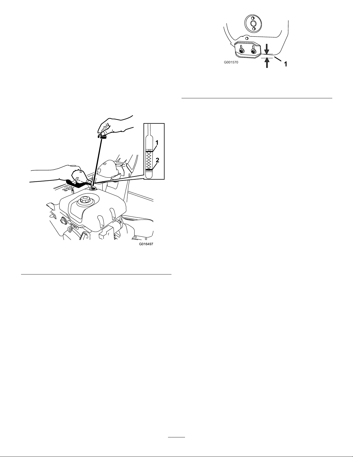
CheckingtheEngine-Oil
G016497
1
2
Level
ServiceInterval:Beforeeachuseordaily—Check
theengine-oillevelandaddoilif
necessary.
1.Removethedipstick,wipeitclean,thenfully
installthedipstick.
2.Removethedipstickandchecktheoillevel
(Figure41).IftheoillevelisbelowtheAddmark
onthedipstick,addoil.RefertoCheckingthe
Engine-OilLevel(page22).
Figure41
1.Full2.Addoil
g001570
Figure42
1.1.3cm(1/2inch)
3.Supportthesideplatessothattheyareatleast
1.3cm(1/2inch)abovealevelsurface.
Important:Theaugerbladesmustbe
supportedabovethegroundbytheskids.
4.Ensurethatthescraperis3mm(1/8inch)above
andparalleltoalevelsurface.
Note:Ifthepavementiscracked,rough,or
uneven,adjusttheskidstoraisethescraper.For
gravelsurfaces,adjusttheskidsfurtherdownto
preventthemachinefrompickinguprocks.
5.Movetheskidsdownuntiltheyareevenwith
theground.
6.Firmlytightenthenutsthatsecurebothskids
totheaugersides.
Note:T oquicklyadjusttheskidsiftheyloosen,
supportthescraper3mm(1/8inch)offthe
pavement,thenadjusttheskidsdowntothe
g016497
pavement.
Note:Iftheskidsbecomeexcessivelyworn,
youcanturnthemoverandsettheunusedside
towardthepavement.
CheckingandAdjustingthe SkidsandScraper
ServiceInterval:Y early—Checktheskidsand
scraperandadjustthemif
necessary.
Checktheskidstoensurethattheaugerdoesnot
contactthepavedorgravelsurface.Adjusttheskids
asneededtocompensateforwear.
1.Checkthetirepressure;referto7Checkingthe
TirePressure(page1 1).
2.Loosenthenutsthatsecurebothskidstothe
augersidesuntiltheskidsslideupanddown
easily(Figure42).
22
Page 23

CheckingandAdjustingthe TractionCable
ServiceInterval:Aftertherst2hours—Inspect
thetractioncableandadjustitif
necessary.
Yearly—Inspectthetractioncableandadjustor
replaceitifnecessary.
Ifthemachinedoesnotdriveintheforwardorreverse
speedsoritdriveswhenyoureleasethetractionlever,
adjustthetractioncable.
g001021
Figure44
Withthetractionleverdisengaged,checkthepin
intheelongatedslotintheleftsideofthemachine
abovethetire.Thereshouldbeagapof1to1.5mm
(1/32to1/16inch)fromthefrontoftheslottothefront
edgeofthepin(Figure43).
Figure43
1.Pin
2.1to1.5mm(1/32to1/16inch)
Iftheleft(traction)cableisnotproperlyadjusted,do
thefollowingsteps:
1.Jamnut2.Turnbuckle
CheckingandAdjustingthe Auger/ImpellerCable
ServiceInterval:Aftertherst2hours—Inspectthe
auger/impellercableandadjustitif
necessary.
Yearly—Inspecttheauger/impellercableand
adjustorreplaceitifnecessary.
1.Removethe2screwsfromtherightsideofthe
beltcoverasshown.
2.Liftuptherightsideofthebeltcover(Figure45).
g001568
1.Loosenthejamnut.
2.Loosenortightentheturnbuckletoadjustthe
pinuntilitisthepropergapfromthefrontedge
oftheslot.
3.Tightenthejamnut(Figure44).
g001022
Figure45
3.Withtheauger/impellerleverdisengaged,
ensurethatthegapbetweentheaugerclutch
assemblyandthetabis1.5mm(1/16inch)as
showninFigure46.
23
Page 24

Figure46
1
G016782
1.Tab
2.1.5mm(1/16inch)
4.Iftheauger/impellercableisnotproperly
adjusted,dothefollowingsteps:
5.Loosenthejamnut(Figure47).
Checkingthe Auger-Gearbox-OilLevel
ServiceInterval:Yearly—Checktheauger-gearbox
oilandaddoilifnecessary.
1.Movethemachinetoalevelsurface.
2.Cleantheareaaroundthepipeplug(Figure48).
g001569
g016782
Figure48
1.Pipeplug
Figure47
1.Jamnut2.Turnbuckle
6.Loosenortightentheturnbucklethatadjuststhe
tensiononthecable(Figure47).
7.Adjusttheturnbuckleuntilyouobtaintheproper
gap.
8.Tightenthejamnut.
9.Insertthe2screwsthatyoupreviouslyremoved
onthebeltcover.
3.Removethepipeplugfromthegearbox.
4.Checktheoillevelinthegearbox.Theoilshould
beatthepointofoverowingatthelleropening.
5.Iftheoillevelislow,addGL-5orGL-6,SAE
85-95EPgearoillubricanttothegearboxuntil
thepointofoverow.
Note:Donotusesyntheticoil.
6.Installthepipepluginthegearbox.
g001024
10.Iftheauger/impellercableisproperlyadjusted
butaproblemremains,contactanAuthorized
ServiceDealer.
24
Page 25
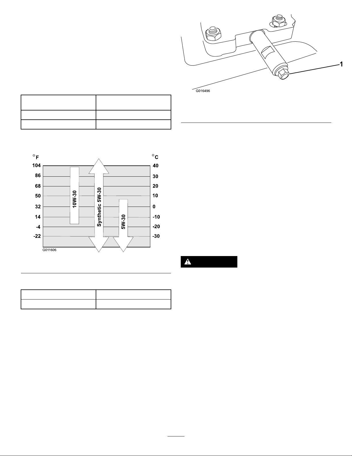
ChangingtheEngineOil
G016496
1
ServiceInterval:Aftertherst5hours—Changethe
engineoil.
Every50hours—Changetheengineoil.
Changetheengineoilevery25operatinghours
whenoperatingtheengineunderaheavyload.
Ifpossible,runtheengineforafewminutesbefore
changingtheoilbecausewarmoilowsbetterand
carriesmorecontaminants.
EngineoilcapacityModels38836:0.89to0.95L
(30to32oz)
OilviscosityRefertoFigure49.
APIserviceclassicationSJorhigher
UseFigure49belowtoselectthebestoilviscosityfor
theoutdoortemperaturerangeexpected:
g016496
Figure50
1.Oil-drainplug
2.Slideanoil-drainpanunderthedrainextension
andremovetheoil-drainplug.
Note:Whenremovingtheplug,ensurethatthe
tubedoesnotloosen.
3.Draintheoil.
Note:Disposeoftheusedoilproperlyatalocal
recyclingcenter.
Figure49
EngineOilCapacities
Model
38836
1.Cleantheareaaroundtheoil-draincap(Figure
50).
EngineOilCapacity
0.89to0.95L(30to32oz)
4.Installtheoil-drainplug.
5.Fillthecrankcasewithoil.
ReplacingtheSparkPlug
ServiceInterval:Every100hours—Replacethe
sparkplug.
g011606
WARNING
Replacingthesparkplugwhiletheengineis
hotcanresultinburns.
Waituntiltheengineiscooltoreplacethe
sparkplug.
UseaT orosparkplugorequivalent(Champion®
RN9YCorNGKBPR6ES).
1.Removetheboot(Figure51).
25
Page 26
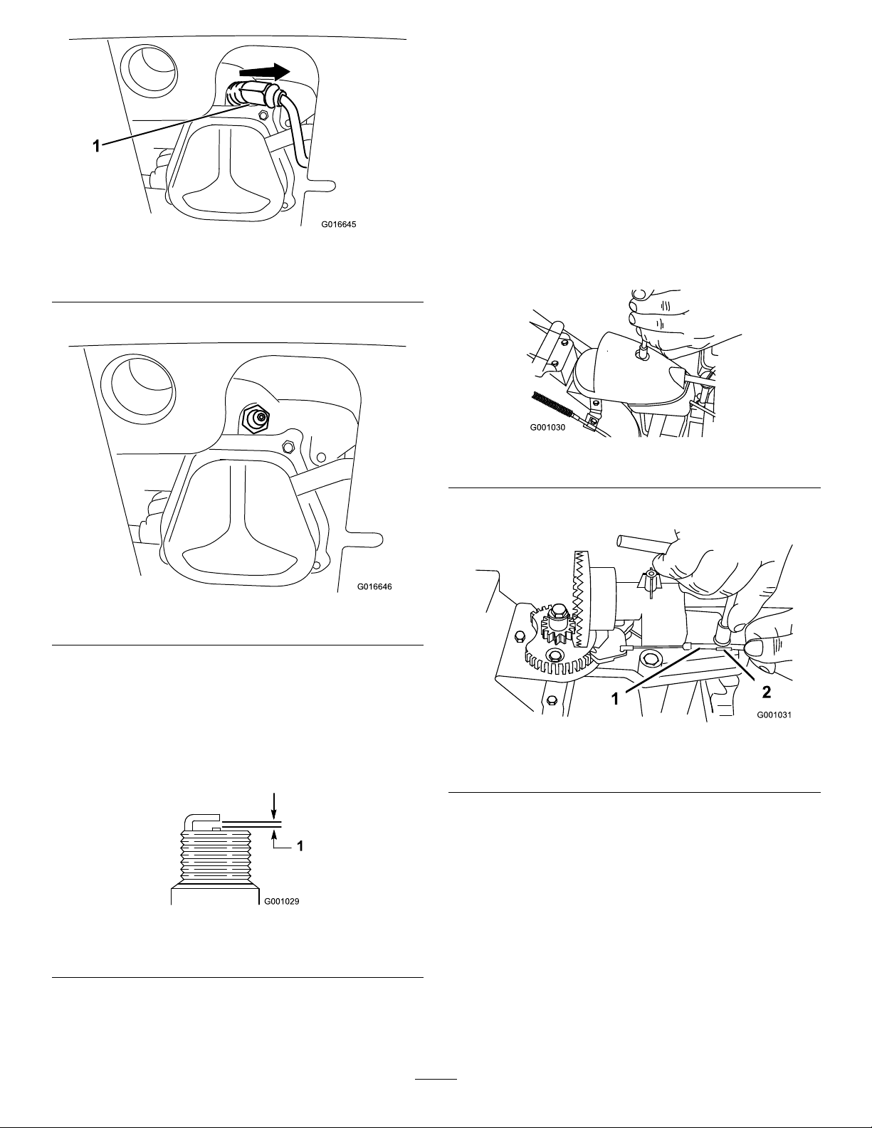
G016645
1
G016646
Note:Ensurethattheignitionwiresnaps
completelyintoplaceonthesparkplug.
Adjustingthe Discharge-ChuteLatch
Ifthedischargechutedoesnotlockintothedesired
positionordoesnotunlocksothatyoucanmoveitto
anotherposition,adjustthedischarge-chutelatch.
Figure51
1.Spark-plugboot
2.Cleanaroundthebaseofthesparkplug.
Figure52
g016645
1.Removethefasteneronthegearcover(Figure
54),liftthefrontofthecoverup,andslideitback
andoutoftheway.
g001030
Figure54
2.Loosentheboltonthecableclamp(Figure55).
g016646
3.Removeanddiscardtheoldsparkplug.
Note:Y ouwillneedaratchetwrenchextension
toremovethesparkplug.
4.Setthegapbetweentheelectrodesonanew
sparkplugat0.76mm(0.030inch)asshown
inFigure53.
Figure53
1.0.76mm(0.030inch)
5.Installthenewsparkplug,tightenitrmly,and
attachtheignitionwiretothesparkplug.
g001031
Figure55
1.Cableconduit2.Cableclamp
3.Graspthecableconduitandmoveittowardthe
frontofthemachineuntilthedischarge-chute
latchfullyengagesthegearteeth(Figure55
andFigure56).
g001029
26
Page 27
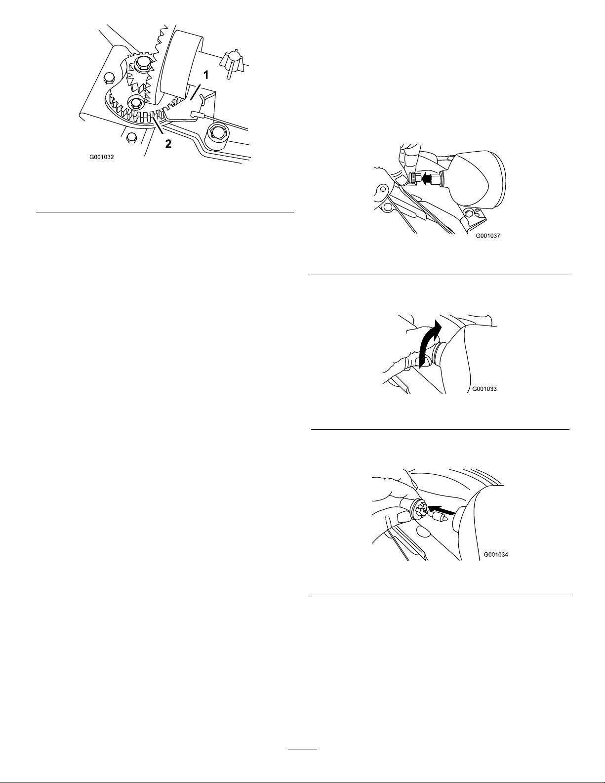
Figure56
ReplacingtheHeadlight Bulb
UseaGE89937Whalogenlightbulb.Donottouch
thebulbwithyourhandsorallowdirtormoistureto
comeintocontactwiththebulb.
1.Removethewireconnectorfromthebackofthe
headlight(Figure57).
g001032
1.Discharge-chutelatch
2.Gearteeth
Note:Thelatchisspringloadedandnaturally
movesintotheteethofthegear(Figure56).
4.Removeanyslackinthecablebypullingthe
cableconduitrearward.
5.Tightentheboltonthecableclamp,being
carefulnottostriptheplasticpart.
6.Installandsecurethegearcover.
ReplacingtheDriveBelts
Iftheauger/impellerdrivebeltorthetraction-drivebelt
becomesworn,oil-soaked,orotherwisedamaged,
haveanAuthorizedServiceDealerreplacethebelt.
g001037
Figure57
2.Turnthebaseofthebulbcounterclockwiseuntil
itstops(Figure58).
g001033
Figure58
3.Removethebulbstraightoutfromthebackof
theheadlight(Figure59).
Figure59
4.Insertanewbulbintothebackoftheheadlight
(Figure60).
27
g001034
Page 28
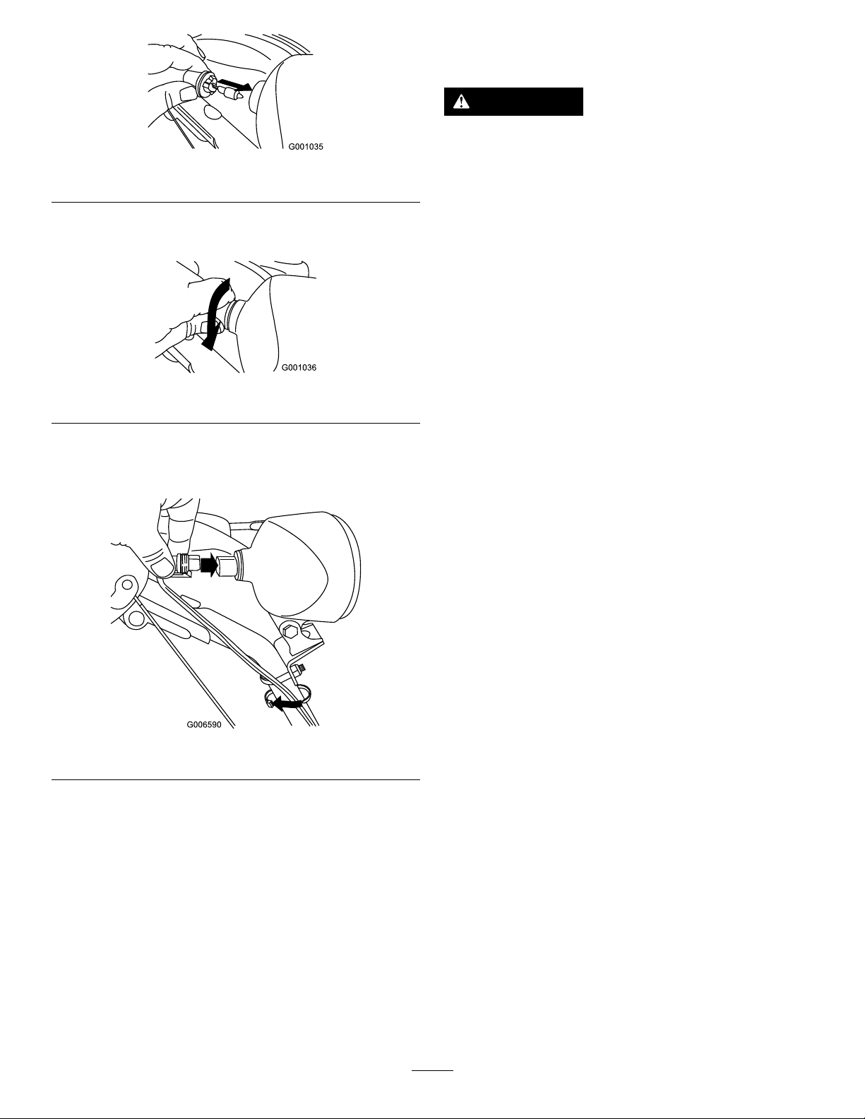
Figure60
5.Turnthebaseofthebulbclockwiseuntilitis
snug(Figure61).
Figure61
6.Insertthewireconnectorstraightintothebackof
theheadlightuntilitissecurelyinplace(Figure
62).
Storage
WARNING
•Gasolinevaporscanexplode.
g001035
g001036
•Donotstoregasolinemorethan30days.
•Donotstorethemachineinanenclosure
nearanopename.
•Allowtheenginetocoolbeforestoringit.
PreparingtheMachinefor Storage
1.Onthelastrefuelingoftheyear,addfuel
stabilizertofreshfuelasdirectedbytheengine
manufacturer.
Important:Donotstorefuellonger
thanthatsuggestedbythefuel-stabilizer
manufacturer.
2.Runtheenginefor10minutestodistributethe
conditionedfuelthroughthefuelsystem.
Figure62
3.Runthemachineuntiltheenginerunsoutoffuel.
4.Primetheengineandstartitagain.
5.Allowtheenginetorununtilitshutsoff.
Whenyoucannolongerstarttheengine,itis
sufcientlydry.
6.Shutofftheengineandallowittocool.
7.Removetheignitionkey.
8.Cleanthemachinethoroughly.
9.Touchupchippedsurfaceswithpaintavailable
fromanAuthorizedServiceDealer.Sand
g006590
affectedareasbeforepainting,andusearust
preventativetopreventthemetalpartsfrom
rusting.
10.Tightenallloosescrews,bolts,andlocknuts.
Repairorreplaceanydamagedparts.
11.Coverthemachineandstoreitinaclean,dry
placeoutofthereachofchildren.
RemovingtheMachine fromStorage
Performtheannualmaintenanceproceduresasgiven
intheRecommendedMaintenanceSchedule;referto
Maintenance(page21).
28
Page 29

Troubleshooting
Problem
Theelectricstarterdoesnotturn(electric
startonly).
Theenginedoesnotstartorstartshard.
PossibleCauseCorrectiveAction
1.Thepowercordisdisconnectedatthe
outletorthemachine.
2.Thepowercordisworn,corroded,or
damaged.
3.Thepoweroutletisnotenergized.
1.Thekeyisnotintheignitionorisinthe
STOPposition.
2.ThechokeisintheOFFpositionand
theprimerhasnotbeenpressed.
3.Thefuel-shutoffvalveisnotopen.3.Openthefuel-shutoffvalve.
4.ThethrottleisnotintheFASTposition.4.MovethethrottletotheFASTposition.
5.Thefueltankisemptyorthefuel
systemcontainsstalefuel.
6.Thespark-plugwireislooseor
disconnected.
7.Thesparkplugispitted,fouled,orthe
gapisincorrect.
8.Thefuel-ventcapisrestricted.
9.Theengine-oillevelintheengine
crankcaseistoolowortoohigh.
1.Connectthepowercordtotheoutlet
and/orthemachine.
2.Replacethepowercord.
3.Haveaqualiedelectricianenergize
theoutlet.
1.Insertthekeyintotheignitionandturn
ittotheONposition.
2.MovethechoketotheONpositionand
presstheprimer3times.
5.Drainand/orllthefueltankwith
freshfuel(notmorethan30daysold).
Iftheproblempersists,contactan
AuthorizedServiceDealer.
6.Connectthewiretothesparkplug.
7.Checkthesparkplugandadjustthe
gapifnecessary .Replacethespark
plugifitispitted,fouled,orcracked.
8.Removetheventrestrictionorreplace
thefuelcap.
9.Addordrainoiltoadjusttheoillevelin
theenginecrankcasetotheFullmark
onthedipstick.
Theenginerunsrough.
1.ThechokeisintheONposition.1.MovethechoketotheOFFposition.
2.Thefuel-shutoffvalveisnotcompletely
open.
3.Thefueltankisnearlyemptyor
containsstalefuel.
4.Thespark-plugwireisloose.
5.Thesparkplugispitted,fouled,orthe
gapisincorrect.
6.Theengine-oillevelintheengine
crankcaseistoolowortoohigh.
2.Openthefuel-shutoffvalve.
3.Drainandllthefueltankwithfresh
fuel(notmorethan30daysold).
Iftheproblempersists,contactan
AuthorizedServiceDealer.
4.Connectthewiretothesparkplug.
5.Checkthesparkplugandadjustthe
gapifnecessary .Replacethespark
plugifitispitted,fouled,orcracked.
6.Addordrainoiltoadjusttheoillevelin
theenginecrankcasetotheFullmark
onthedipstick.
29
Page 30

Problem
PossibleCauseCorrectiveAction
Theengineruns,butthemachine
dischargessnowpoorlyornotatall.
Thedischargechuteeitherdoesnotlock
intoplaceordoesnotmove.
Themachinedoesnotproperlyclearthe
snowoffthesurface.
1.ThethrottleisnotintheFASTposition
whenthrowingsnow .
2.Themachineismovingtoofasttoclear
thesnow.
3.Y ouaretryingtoremovetoomuch
snowperswath.
4.Y ouaretryingtoremoveextremely
heavyorwetsnow.
5.Thedischargechuteisplugged.5.Unclogthedischargechute.
6.Theauger/impellerdrivebeltisloose
orisoffthepulley.
7.Theauger/impellerdrivebeltisworn
orbroken.
1.Thedischarge-chutelatchisnot
properlyadjusted.
1.Theskidsand/orscraperarenot
properlyadjusted.
2.Thepressureinthetiresisnotequal.
1.MovethethrottletotheFASTposition.
2.Shiftthemachineintoalowergear.
3.Reducetheamountofsnowremoved
perswath.
4.Don'toverloadthemachinewith
extremelyheavyorwetsnow.
6.Installand/oradjusttheauger/impeller
drivebelt;refertowww.Toro.com
forservicinginformationortakethe
machinetoanAuthorizedService
Dealer.
7.Replacetheauger/impellerdrivebelt;
refertowww.Toro.comforservicing
informationortakethemachinetoan
AuthorizedServiceDealer.
1.Adjustthedischarge-chutelatch.
1.Adjusttheskidsand/orthescraper.
2.Checkandadjustthepressurein1or
bothtires.
30
Page 31

Notes:
Page 32

EuropeanPrivacyNotice
TheInformationT oroCollects
ToroWarrantyCompany(T oro)respectsyourprivacy .Inordertoprocessyourwarrantyclaimandcontactyouintheeventofaproductrecall,weaskyou
tosharecertainpersonalinformationwithus,eitherdirectlyorthroughyourlocalT orocompanyordealer.
TheTorowarrantysystemishostedonserverslocatedwithintheUnitedStateswhereprivacylawmaynotprovidethesameprotectionasapplies
inyourcountry.
BYSHARINGYOURPERSONALINFORMATIONWITHUS,YOUARECONSENTINGTOTHEPROCESSINGOFYOURPERSONALINFORMATION
ASDESCRIBEDINTHISPRIV ACYNOTICE.
TheWayT oroUsesInformation
Toromayuseyourpersonalinformationtoprocesswarrantyclaims,tocontactyouintheeventofaproductrecallandforanyotherpurposewhichwetell
youabout.T oromayshareyourinformationwithT oro'safliates,dealersorotherbusinesspartnersinconnectionwithanyoftheseactivities.Wewillnot
sellyourpersonalinformationtoanyothercompany .Wereservetherighttodisclosepersonalinformationinordertocomplywithapplicablelawsand
withrequestsbytheappropriateauthorities,tooperateoursystemsproperlyorforourownprotectionorthatofotherusers.
RetentionofyourPersonalInformation
Wewillkeepyourpersonalinformationaslongasweneeditforthepurposesforwhichitwasoriginallycollectedorforotherlegitimatepurposes
(suchasregulatorycompliance),orasrequiredbyapplicablelaw.
Toro'sCommitmenttoSecurityofY ourPersonalInformation
Wetakereasonableprecautionsinordertoprotectthesecurityofyourpersonalinformation.Wealsotakestepstomaintaintheaccuracyandcurrent
statusofpersonalinformation.
AccessandCorrectionofyourPersonalInformation
Ifyouwouldliketorevieworcorrectyourpersonalinformation,pleasecontactusbyemailatlegal@toro.com.
AustralianConsumerLaw
AustraliancustomerswillnddetailsrelatingtotheAustralianConsumerLaweitherinsidetheboxoratyourlocalToroDealer .
374-0282RevC
 Loading...