

Toro Power Max 1128 OXE 38828, 38828 Power Max HD 1128 OXE Operator's Manual
FormNo.3373-868RevB
PowerMaxHeavyDuty1128OXESnowthrower
ModelNo.38828—SerialNo.313000001andUp
Operator'sManual
Introduction
Thismachineisintendedtobeusedbyresidential
homeownersorprofessional,hiredoperators.Itis
designedprimarilyforremovingsnowfrompaved
surfaces,suchasdrivewaysandsidewalks,andother
surfacesfortrafconresidentialorcommercial
properties.Itisnotdesignedforremovingmaterials
otherthansnow,norisamodelwithapivotingscraper
designedforclearingoffgravelsurfaces.
Readthisinformationcarefullytolearnhowtooperateand
maintainyourmachineproperlyandtoavoidinjuryand
machinedamage.Youareresponsibleforoperatingthe
machineproperlyandsafely.
YoumaycontactTorodirectlyatwww .Toro.comformachine
andaccessoryinformation,helpndingadealer,ortoregister
yourmachine.
Wheneveryouneedservice,genuineToroparts,oradditional
information,contactanAuthorizedServiceDealerorToro
CustomerServiceandhavethemodelandserialnumbersof
yourmachineready.Figure1identiesthelocationofthe
modelandserialnumbersonthemachine.Writethenumbers
inthespaceprovided.
Figure1
1.Modelandserialnumberlocation
ModelNo.
SerialNo.
Thismanualidentiespotentialhazardsandhassafety
messagesidentiedbythesafetyalertsymbol(Figure2),
whichsignalsahazardthatmaycauseseriousinjuryordeath
ifyoudonotfollowtherecommendedprecautions.
Figure2
1.Safetyalertsymbol
Thismanualuses2wordstohighlightinformation.
Importantcallsattentiontospecialmechanicalinformation
andNoteemphasizesgeneralinformationworthyofspecial
attention.
ReplacementEngineOwner’sManualsmaybeordered
throughtheenginemanufacturer.
Contents
Introduction..................................................................1
Training.................................................................3
Preparation.............................................................3
Operation...............................................................3
MaintenanceandStorage..........................................4
ToroSnowthrowerSafety.........................................4
SoundPressure.......................................................4
SoundPower..........................................................4
Vibration................................................................4
SafetyandInstructionalDecals.................................4
Setup............................................................................7
1InstallingtheUpperHandle....................................7
2InstallingtheWheelClutchCableEnds....................8
3InstallingtheTractionControlLinkage....................9
4InstallingtheChuteControlRod............................10
5ConnectingtheWiretotheHeadlight......................11
6FillingtheEnginewithOil.....................................11
7CheckingtheTirePressure....................................12
8CheckingtheSkids...............................................12
9CheckingtheTractionDriveOperation...................12
ProductOverview.........................................................13
Operation....................................................................14
FillingtheFuelTank...............................................14
StartingtheEngine.................................................14
StoppingtheEngine...............................................16
OperatingtheTractionDrive...................................16
UsingtheWheelClutchLevers.................................17
OperatingtheSpeedSelector...................................17
OperatingtheAuger/ImpellerDrive.........................17
©2012—TheToro®Company
8111LyndaleAvenueSouth
Bloomington,MN55420
Registeratwww.Toro.com.
OriginalInstructions(EN)
PrintedintheUSA
AllRightsReserved
*3373-868*B

OperatingtheQuickStick®......................................17
UncloggingtheDischargeChute..............................18
PreventingFreeze-up..............................................18
OperatingTips......................................................19
Maintenance.................................................................20
RecommendedMaintenanceSchedule(s)......................20
PreparingforMaintenance.......................................21
CheckingtheEngineOilLevel.................................21
CheckingandAdjustingtheSkids.............................21
CheckingandAdjustingtheTractionCable................21
CheckingtheAugerGearboxOilLevel......................22
ChangingtheEngineOil.........................................22
AdjustingtheDischargeChuteLatch........................23
ReplacingtheDriveBelts.........................................24
ReplacingtheHeadlightBulb...................................24
Storage........................................................................25
PreparingtheMachineforStorage............................25
RemovingtheMachinefromStorage.........................25
Troubleshooting...........................................................26
2

Safety
ThismachinemeetsorexceedstheISOstandard8437
ineffectatthetimeofproduction.
Readandunderstandthecontentsofthismanualbefore
theengineiseverstarted.
Thisisthesafetyalertsymbol.Itisusedtoalertyou
topotentialpersonalinjuryhazards.Obeyallsafety
messagesthatfollowthissymboltoavoidpossibleinjury
ordeath.
Improperlyusingormaintainingthismachinecould
resultininjuryordeath.Toreducethispotential,
complywiththefollowingsafetyinstructions.
Training
•Readtheoperatingandserviceinstructionmanual
carefully.Bethoroughlyfamiliarwiththecontrolsand
theproperuseofthemachine.Knowhowtostopthe
machineanddisengagethecontrolsquickly.
•Neverallowchildrentooperatethemachine.Neverallow
adultstooperatethemachinewithoutproperinstruction.
•Keeptheareaofoperationclearofallpersons,particularly
smallchildren,andpets.
•Exercisecautiontoavoidslippingorfalling,especially
whenoperatinginreverse.
Preparation
•Thoroughlyinspecttheareawherethemachineistobe
usedandremovealldoormats,sleds,boards,wires,and
otherforeignobjects.
•Disengageallclutchesandshiftintoneutralbefore
startingtheengine.
•Donotoperatethemachinewithoutwearingadequate
wintergarments.Wearfootwearwhichwillimprove
footingonslipperysurfaces.
•Handlefuelwithcare;itishighlyammable.
–Useanapprovedfuelcontainer.
–Neveraddfueltoarunningorhotengine.
–Fillfueltankoutdoorswithextremecare.Neverll
fueltankindoors.
–Replacegasolinecapssecurelyandwipeupspilled
fuel.
•Adjustthecollectorhousingheighttocleargravelor
crushedrocksurface.
•Neverattempttomakeanyadjustmentswhiletheengine
isrunning(exceptwherespecicallyrecommendedby
manufacturer).
•Letengineandmachineadjusttooutdoortemperatures
beforestartingtoclearsnow.
•Theoperationofanypoweredmachinecanresultin
foreignobjectsbeingthrownintotheeyes.Alwayswear
safetyglassesoreyeshieldsduringoperationorwhile
performinganadjustmentorrepair.
Operation
•Donotputhandsorfeetnearorunderrotatingparts.
Keepclearofthedischargeopeningatalltimes.
•Exerciseextremecautionwhenoperatingonorcrossing
graveldrives,walks,orroads.Stayalertforhidden
hazardsortrafc.
•Afterstrikingaforeignobject,stoptheengine,remove
thewirefromthespark-plug,thoroughlyinspectthe
machineforanydamage,andrepairthedamagebefore
restartingandoperatingthemachine.
•Ifthemachineshouldstarttovibrateabnormally,stopthe
engineandcheckimmediatelyforthecause.Vibrationis
generallyawarningoftrouble.
•Stoptheenginewheneveryouleavetheoperating
position,beforeuncloggingthecollector/impeller
housingordischargeguide,andwhenmakinganyrepairs,
adjustments,orinspections.
•Whencleaning,repairing,orinspecting,makecertainthe
collector/impellerandallmovingpartshavestopped.
Disconnectthespark-plugwire,andkeepthewireaway
fromtheplugtopreventaccidentalstarting.
•Donotruntheengineindoors,exceptwhenstartingit
andformovingthemachineinoroutofthebuilding.
Opentheoutsidedoors;exhaustfumesaredangerous.
•Donotclearsnowacrossthefaceofslopes.Exercise
extremecautionwhenchangingdirectiononslopes.Do
notattempttoclearsteepslopes.
•Neveroperatethemachinewithoutproperguards,plates,
orothersafetyprotectivedevicesinplace.
•Neveroperatethemachinenearglassenclosures,
automobiles,windowwells,drop-offs,etc.withoutproper
adjustmentofthesnowdischargeangle.Keepchildren
andpetsaway.
•Donotoverloadthemachinecapacitybyattemptingto
clearsnowattoofastarate.
•Neveroperatethemachineathightransportspeedson
slipperysurfaces.Usecarewhenreversing.
•Neverdirectdischargeatbystandersorallowanyonein
frontofthemachine.
•Disengagepowertothecollector/impellerwhenmachine
istransportedornotinuse.
•Useonlyattachmentsandaccessoriesapprovedby
themanufacturerofmachine(suchaswheelweights,
counterweights,cabs,etc.).
•Neveroperatethemachinewithoutgoodvisibilityor
light.Alwaysbesureofyourfooting,andkeeparm
holdonthehandles.W alk;neverrun.
3

•Neveroperatethemachinewithoutgoodvisibilityor
light.
•Takeallpossibleprecautionswhenleavingthemachine
unattended.Shiftintoneutral,settheparkingbrake,stop
theengineandremovethekey.
MaintenanceandStorage
•Checkallfastenersatfrequentintervalsforproper
tightnesstobesurethemachineisinsafeworking
condition.
•Neverstorethemachinewithfuelinthefueltankinsidea
buildingwhereignitionsourcesarepresentsuchashot
waterandspaceheaters,clothesdryers,etc.Allowthe
enginetocoolbeforestoringinanyenclosure.
•Alwaysrefertoowner’sguideinstructionsforimportant
detailsifthemachineistobestoredforanextended
period.
•Maintainorreplacesafetyandinstructionslabels,as
necessary.
•Runthemachineafewminutesafterthrowingsnowto
preventfreeze-upofthecollector/impeller.
ToroSnowthrowerSafety
ThefollowinglistcontainssafetyinformationspecictoToro
productsorothersafetyinformationthatyoumustknow .
•Rotatingrotorbladescaninjurengersorhands.
Staybehindthehandlesandawayfromthedischarge
openingwhileoperatingthemachine.Keepyourface,
hands,feet,andanyotherpartofyourbodyor
clothingawayfrommovingorrotatingparts.
•Beforeadjusting,cleaning,repairing,andinspectingthe
machine,andbeforeuncloggingthedischargechute,stop
theengine,removethekey,andwaitforallmoving
partstostop.
•Usethesnowcleanouttool,notyourhands,toremove
obstructionsfromthedischargechute.
•Beforeleavingtheoperatingposition,stoptheengine,
removethekey,andwaitforallmovingpartstostop.
•Donotwearloose-ttingclothingthatcouldgetcaught
inmovingparts.
•Ifashield,safetydevice,ordecalisdamaged,illegible,or
lost,repairorreplaceitbeforebeginningoperation.Also,
tightenanyloosefasteners.
•Donotsmokewhilehandlinggasoline.
•Donotusethemachineonaroof.
•Donottouchtheenginewhileitisrunningorsoonafter
ithasstoppedbecausetheenginemaybehotenoughto
causeaburn.
•Performonlythosemaintenanceinstructionsdescribedin
thismanual.Beforeperforminganymaintenance,service,
oradjustment,stoptheengine,removethekey,and
disconnectthewirefromthesparkplug.Ifmajorrepairs
areeverneeded,contactanAuthorizedServiceDealer.
•Donotchangethegovernorsettingsontheengine.
•Whenstoringthemachineformorethan30days,drain
thefuelfromthefueltanktopreventapotentialhazard.
Storefuelinanapprovedfuelcontainer.Removethekey
fromtheignitionswitchbeforestoringthemachine.
•PurchaseonlygenuineTororeplacementpartsand
accessories.
SoundPressure
Thismachinehasasoundpressurelevelattheoperator’sear
of91dBA,whichincludesanUncertaintyValue(K)of1
dBA.Thesoundpressurelevelwasdeterminedaccordingto
theproceduresoutlinedinENISO11201.
SoundPower
Thismachinehasaguaranteedsoundpowerlevelof105
dBA,whichincludesanUncertaintyValue(K)of2dBA.
Thesoundpowerlevelwasdeterminedaccordingtothe
proceduresoutlinedinENISO3744.
Vibration
Measuredvibrationlevelforthelefthand=7.1m/s
2
.
Measuredvibrationlevelfortherighthand=5.5m/s
2
.
UncertaintyValue(K)=2.8m/s
2
.
Themeasuredvaluesweredeterminedaccordingtothe
proceduresoutlinedinENISO20643.
SafetyandInstructional
Decals
Important:Safetyandinstructiondecalsarelocated
nearareasofpotentialdanger.Replacedamageddecals.
4
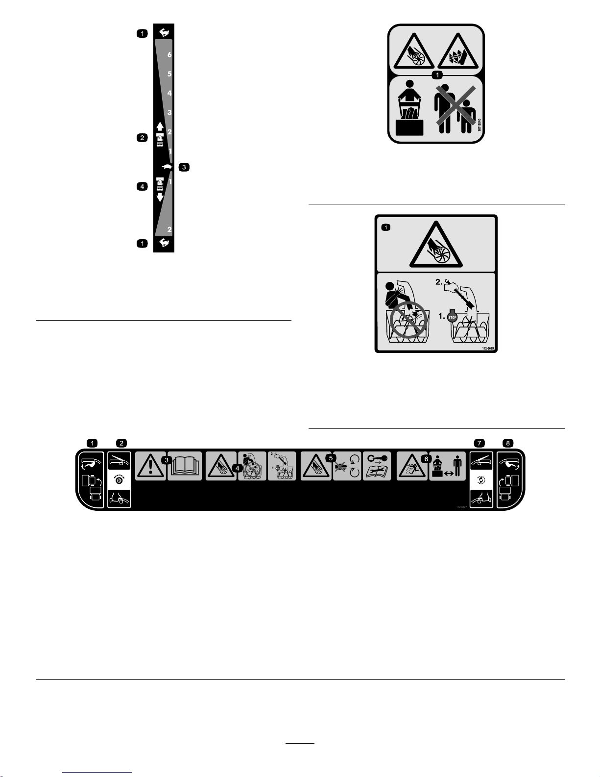
106-4525
Reorderpartno.112-6633
1.Fast
3.Slow
2.Forwardspeeds4.Reversespeeds
107-3040
1.Cuttingdismemberment,impellerandcutting
dismemberment,augerhazards—keepbystandersasafe
distancefromthemachine.
112-6625
Reorderpartno.112-6629
1.Cutting/dismembermenthazard,impeller—donotplace
yourhandinthechute;stoptheenginebeforeleavingthe
operator'sposition,usethetooltoclearthechute.
112-6627
1.Leftturncontrol
3.Warning—readthe
Operator'sManual.
5.Cutting/dismemberment
hazard,impeller—keep
awayfrommovingparts;
removetheignitionkeyand
readtheinstructionsbefore
servicingorperforming
maintenance.
7.Auger/impeller
drive—squeezetheleverto
engage;releasethelever
todisengage.
2.Tractiondrive—squeeze
thelevertoengage;release
thelevertodisengage.
4.Cutting/dismemberment
hazard,impeller—do
notplaceyourhand
inthechute;stopthe
enginebeforeleavingthe
operator'sposition,usethe
tooltoclearthechute.
6.Thrownobject
hazard—keepbystanders
asafedistancefromthe
machine.
8.Rightturncontrol
5
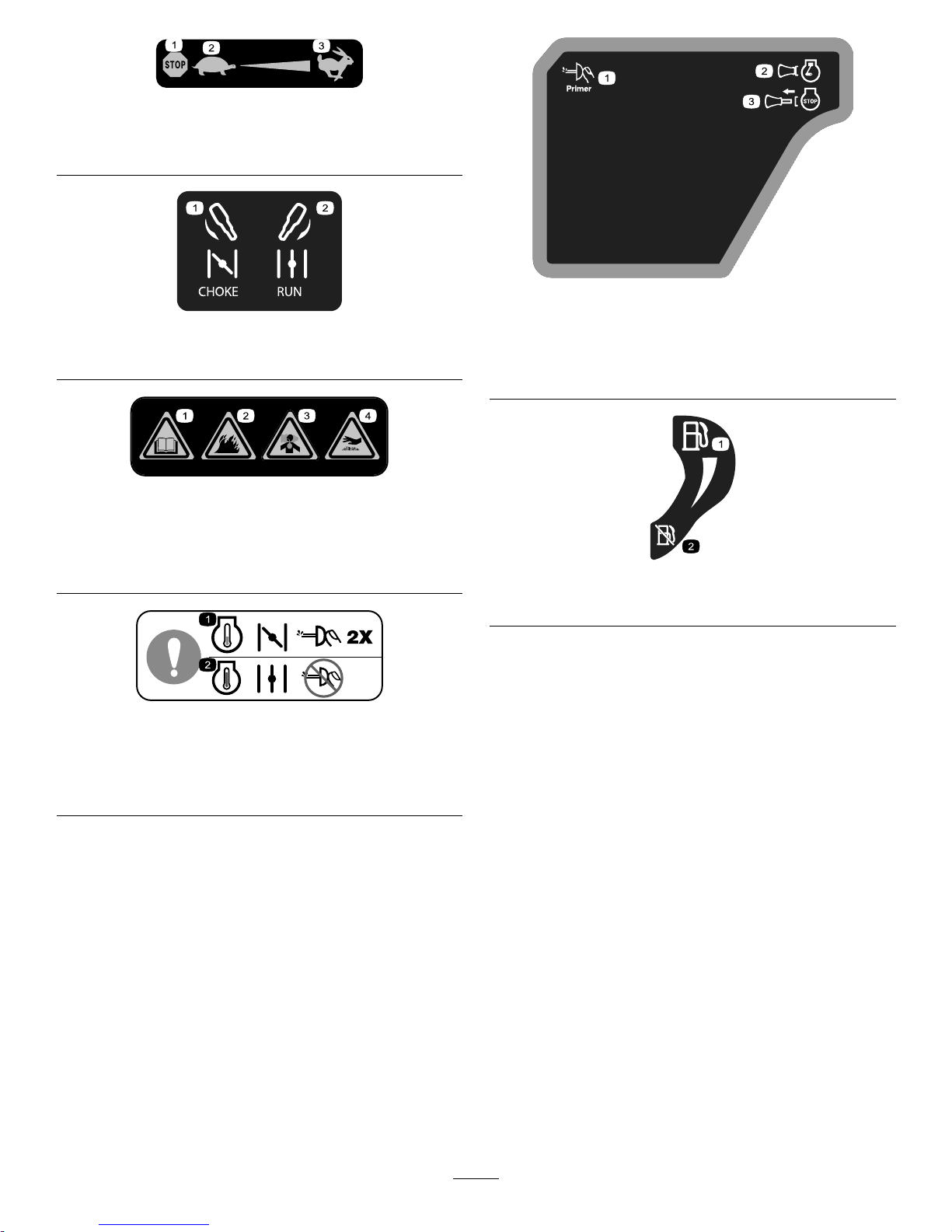
Briggs&StrattonPartNo.273676
1.Stop
3.Fast
2.Slow
Briggs&StrattonPartNo.275949
1.Chokeon(Choke)2.Chokeoff(Run)
Briggs&StrattonPartNo.276925
1.Warning—readthe
Operator'sManual.
3.Warning—toxicgas
inhalationhazard.
2.Warning—rehazard.
4.Warning—hot
surface/burnhazard.
Briggs&StrattonPartNo.277566
1.Whenstartingacold
engine,closethechoke
andpresstheprimertwo
times.
2.Whenstartingawarm
engine,openthechoke
anddonotpressthe
primer.
Briggs&StrattonPartNo.277588
1.Primer3.Ignitionkeyout
(Engine—Stop)
2.Ignitionkeyin
(Engine—Run)
Briggs&StrattonPartNo.278866
1.Fuel—On2.Fuel—Off
6
Setup
LooseParts
Usethechartbelowtoverifythatallpartshavebeenshipped.
ProcedureDescription
Qty.
Use
Handlebolts4
Curvedwashers
4
1
Locknuts4
Installtheupperhandle.
2
Nopartsrequired
–
Installthewheelclutchcableends
3
Nopartsrequired
–
Installthetractioncontrollinkage.
Carriagebolts
2
4
Locknuts2
Installthechutecontrolrod.
5
Cabletie
1
Connectthewiretotheheadlight.
6
Nopartsrequired
–
Filltheenginewithoil.
7
Nopartsrequired
–
Checkthetirepressure.
8
Nopartsrequired
–
Checktheskids.
9
Nopartsrequired
–
Checktheoperationofthetractiondrive.
1
InstallingtheUpperHandle
Partsneededforthisprocedure:
4Handlebolts
4
Curvedwashers
4Locknuts
Procedure
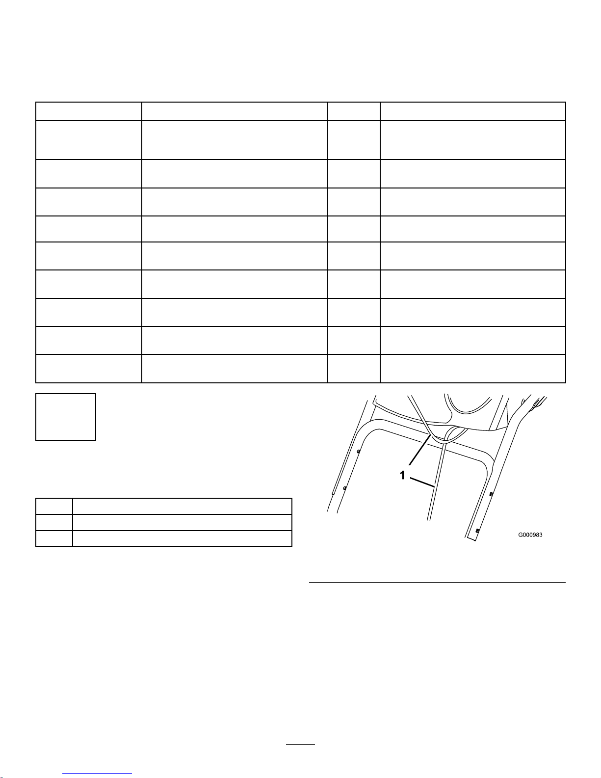
Note:Donotremovetherubberbandonthecablesuntil
youhaveinstalledtheupperhandle.
1.Liftandrotatetheupperhandleandpositionitover
thelowerhandle(
Figure3).
Important:Routethecablesattachedtothe
QuickStickinsidetheupperhandlelegsand
ensurethatthecablesandthewireforthe
headlightarenotpinchedbetweenthehandle
sections.
Figure3
1.Cables
2.Securetheupperhandlewith4handlebolts,4curved
washers,and4locknutsfromtheloosepartsbag
(Figure4).
7
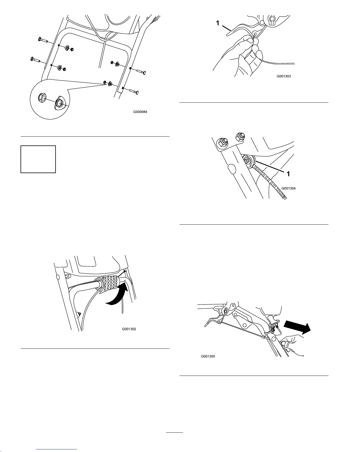
Figure4
2
InstallingtheWheelClutch
CableEnds
NoPartsRequired
Procedure
1.Unwrapthecableendsfromthelowerhandle
(Figure5).
Figure5
2.Routeeithertheleftorrightcableendoverthelower
handleandinsertthecableendintotheholeinthe
correspondingwheelclutchlever(Figure6).
Figure6
1.Wheelclutchlever
3.Removethenutandwasherfromthehandle,attach
thecableclamponthecabletothehandle,installthe
washerandthenut,andhandtightenthenut(Figure7).
Figure7
1.Cableclamp(2)
Important:Ensurethatthecurvedsideofthe
cableclampisagainstthehandleandthatthe
cableisroutedbelowtheclampbolt.Thecable
mustbeinastraightlinefromthecableclamp
tothepointwhereitattachestothewheelclutch
lever.
4.Pullthecablejacketdowngentlyuntilthewheelclutch
leverisdownandtheslackisoutofthecable,then
tightenthecableclampnutsecurely(Figure8).
Figure8
5.Squeezetheleverfully,thencheckthegapbetween
thebottomofthehandleandthewheelclutchlever
end(Figure9).
8
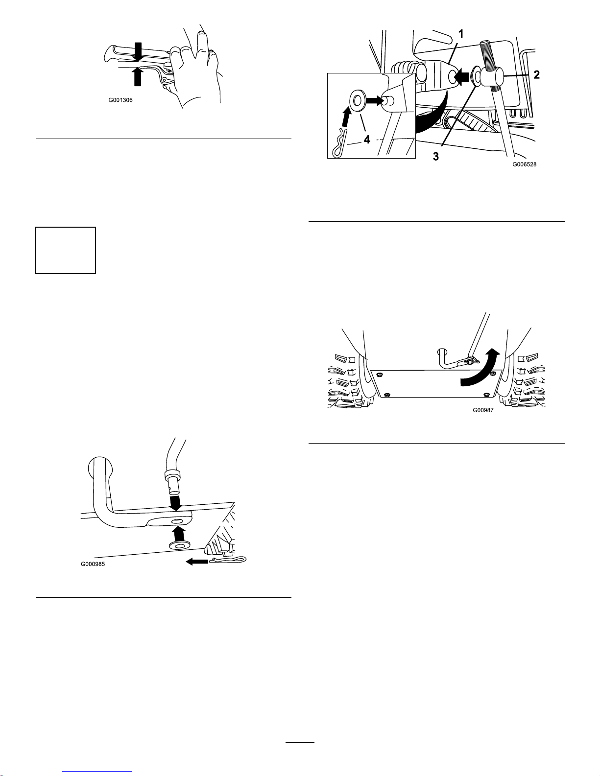
Figure9
Note:Thegapshouldbeapproximatelythethickness
ofapencil(1/4inchor6mm).Ifitisgreater,loosen
thecableclampnut,slidethecablejacketupslightly ,
tightenthecableclampnut,andcheckthegapagain.
6.Repeatsteps2through5fortheothercable.
3
InstallingtheTractionControl
Linkage
NoPartsRequired
Procedure
1.Removethehairpincotterandwasherfromthelower
endofthespeedcontrolrodandinsertthelowerend
oftherodintothelowerlinkarmsothatthebentend
ofthespeedcontrolrodfacesrearward(Figure10).
Figure10
2.Securethelowerendofthespeedcontrolrodwiththe
washerandhairpincotterthatyoupreviouslyremoved.
3.Removethehairpincotterandtheouterwasherfrom
thetrunnionontheupperendofthespeedcontrol
rod(Figure11).
Figure11
1.Speedselectorlever
3.Innerwasher
2.Trunnion
4.Outerwasher
Note:Tomakeinstallationeasier,leavetheatwasher
onthetrunnion(Figure11).
4.ShiftthespeedselectorleverintoPositionR2.
5.Rotatethelowerlinkarmfullyupward
(counterclockwise)(Figure12).
Figure12
6.Liftuponthespeedcontrolrodandinsertthetrunnion
intotheholeinthespeedselectorlever(Figure11).
Note:Ifthetrunniondoesnottintothehole
whenyouliftuponthespeedcontrolrod,rotatethe
trunnionupwardordownwardonthespeedcontrol
roduntilitts.
7.Securethetrunnionandupperendofthespeedcontrol
rodwiththeouterwasherandahairpincotteryou
previouslyremoved.
9
Note:Foreasierinstallation,lookdownthroughthe
openinginthespeedselector(Figure13).
Figure13
1.Speedselector
4
InstallingtheChuteControl
Rod
Partsneededforthisprocedure:
2
Carriagebolts
2Locknuts
Procedure
1.UnwraptheQuickStickandrotateitsothatitis
uprightandinthecenter.
2.Holdthebluetriggercapdownandpulltheleverfully
rearward.
Note:Thedischargechuteanddeectorshouldface
forward.Iftheydonot,holdthebluetriggercap
down(butdonotmovetheQuickStick)androtatethe
dischargechuteuntiltheydo.
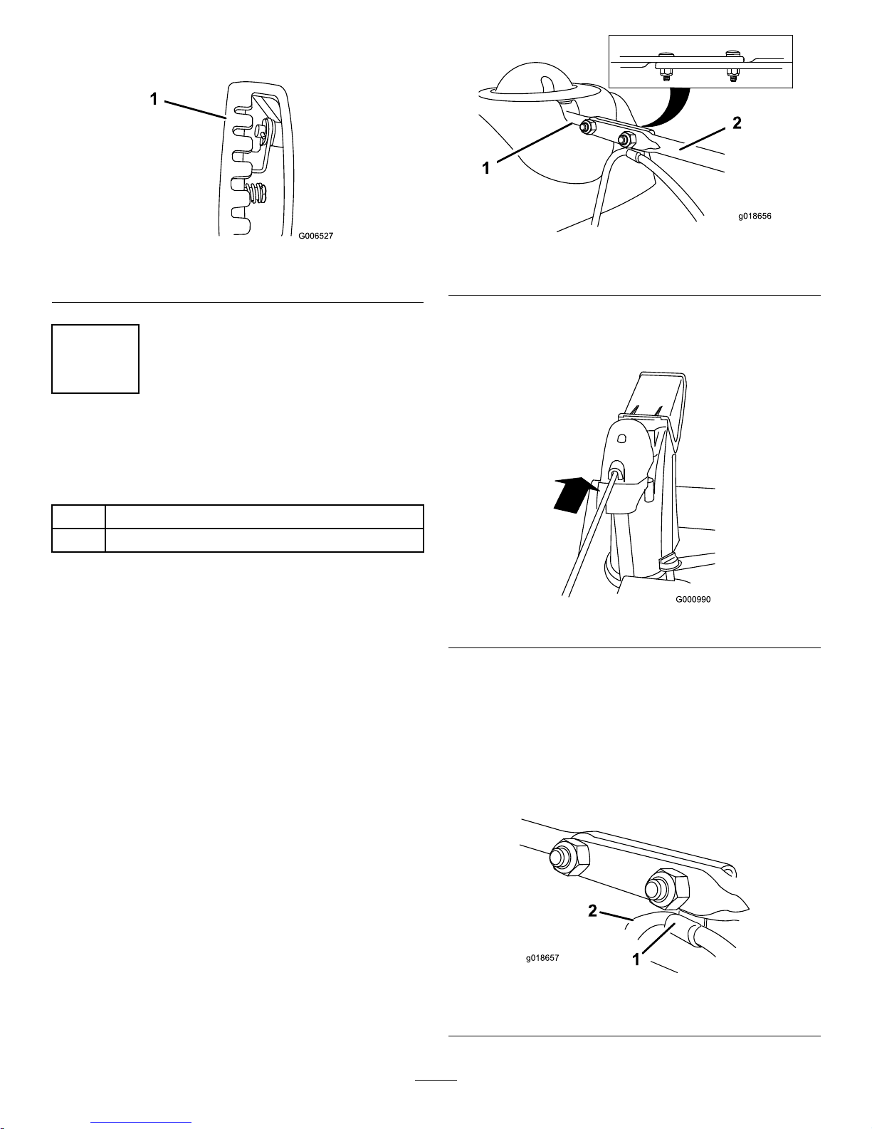
3.Aligntheattenedbackendofthelongchutecontrol
rodwiththeattenedfrontendoftheshortrod
thatextendsfromthecontrolpanelsothattheynest
together(Figure14).
g018656
Figure14
1.Shortrod
2.Longchutecontrolrod
4.Insertthefrontendoftherodintotheopeningin
thebackofthechutegearcoveruntilitslidesintothe
chutegear(Figure15).
Figure15
5.Aligntheholesinthenestedendsoftherodsand
insert2carriagebolts(intheloosepartsbag)through
theshortrodfromtheleftsideofthemachine(from
theoperatingposition).
6.Insertthecableclipthatsupportsthedeectorcable
undertheheadoftheforwardcarriagebolt,andsecure
thecarriageboltswithlocknutsfromthelooseparts
bag(Figure16).
g018657
Figure16
1.Cableclip2.Deectorcable
10
 Loading...