


PowerBroom
38701
KehrmaschinePowerBroom
38701
Barredora
38701
Balayeuseélectrique
38701
FormNo.3439-918RevB
Motoraangedrevenrolbezem
38701
www.T oro.com.
*3439-918*

FormNo.3439-892RevB
PowerBroom
ModelNo.38701—SerialNo.400000000andUp
Registeratwww.T oro.com.
OriginalInstructions(EN)
*3439-892*
ItisaviolationofCaliforniaPublicResourceCode
Section4442or4443touseoroperatetheengineon
anyforest-covered,brush-covered,orgrass-covered
landunlesstheengineisequippedwithaspark
arrester,asdenedinSection4442,maintainedin
effectiveworkingorderortheengineisconstructed,
equipped,andmaintainedforthepreventionofre.
Theenclosedengineowner'smanualissupplied
forinformationregardingtheUSEnvironmental
ProtectionAgency(EPA)andtheCaliforniaEmission
ControlRegulationofemissionsystems,maintenance,
andwarranty.Replacementsmaybeorderedthrough
theenginemanufacturer.
WARNING
CALIFORNIA
Proposition65Warning
Theengineexhaustfromthisproduct
containschemicalsknowntotheStateof
Californiatocausecancer,birthdefects,
orotherreproductiveharm.
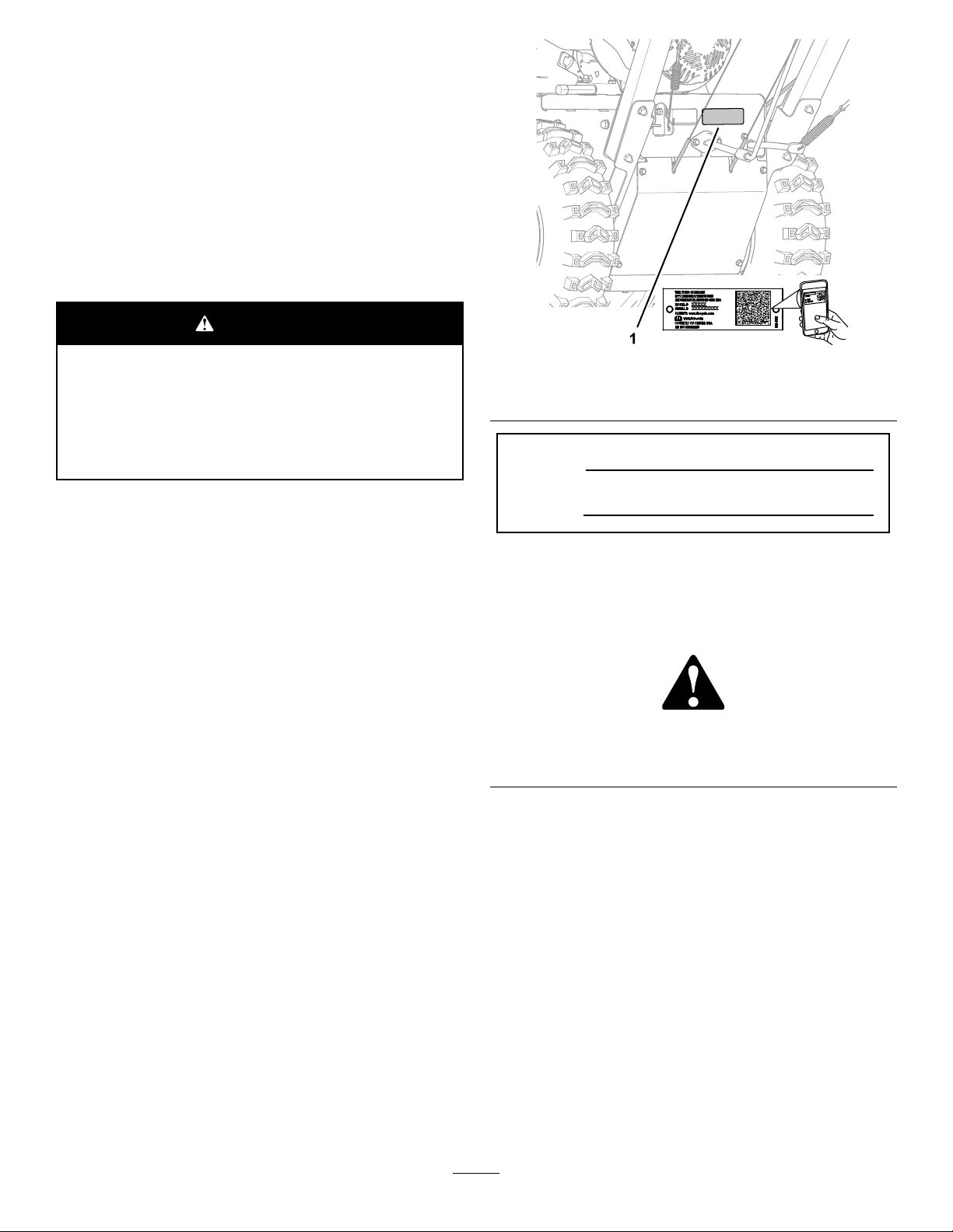
g325100
Figure1
1.Modelandserial-numberlocation
ModelNo.
Introduction
Thismachineisintendedtobeusedbyresidential
homeownersorprofessional,hiredoperators.Itis
designedforremovingsnow,dust,anddirtfrompaved
surfaces,suchasdrivewaysandsidewalks,and
othersurfacesfortrafconresidentialorcommercial
properties,aswellasthatchfromgrass.
Readthisinformationcarefullytolearnhowtooperate
andmaintainyourproductproperlyandtoavoid
injuryandproductdamage.Youareresponsiblefor
operatingtheproductproperlyandsafely .
Visitwww.Toro.comforproductsafetyandoperation
trainingmaterials,accessoryinformation,helpnding
adealer,ortoregisteryourproduct.
Wheneveryouneedservice,genuineToroparts,or
additionalinformation,contactanAuthorizedService
DealerorToroCustomerServiceandhavethemodel
andserialnumbersofyourproductready.Figure1
identiesthelocationofthemodelandserialnumbers
ontheproduct.Writethenumbersinthespace
provided.
SerialNo.
Thismanualidentiespotentialhazardsandhas
safetymessagesidentiedbythesafety-alertsymbol
(Figure2),whichsignalsahazardthatmaycause
seriousinjuryordeathifyoudonotfollowthe
recommendedprecautions.
g000502
Figure2
1.Safety-alertsymbol
Thismanualuses2wordstohighlightinformation.
Importantcallsattentiontospecialmechanical
informationandNoteemphasizesgeneralinformation
worthyofspecialattention.
Important:Withyourmobiledevice,youcan
scantheQRcodeontheserialnumberdecal(if
equipped)toaccesswarranty,parts,andother
productinformation.
©2020—TheToro®Company
8111LyndaleAvenueSouth
Bloomington,MN55420
Contactusatwww.Toro.com.
2
PrintedintheUSA
AllRightsReserved

Contents
Safety
Safety.......................................................................3
GeneralSafety...................................................3
SlopeIndicator...................................................4
SafetyandInstructionalDecals..........................5
ProductOverview.....................................................7
Controls.............................................................7
Specications....................................................8
Attachments/Accessories...................................8
BeforeOperation...................................................9
BeforeOperationSafety.....................................9
FillingtheFuelTank............................................9
CheckingtheSweepingPath..............................9
AdjustingtheBroomHeight..............................10
DuringOperation.................................................10
DuringOperationSafety...................................10
OperatingtheEngine.........................................1 1
DrivingtheMachine..........................................13
OperatingtheBroom........................................14
AdjustingtheBroomSideAngle........................15
UsingtheAlternateCasterLocation..................16
ClearingaCloggedBroom................................16
AfterOperation....................................................16
AfterOperationSafety......................................16
PreventingFreeze-upafterUse........................17
TransportingtheMachine.................................17
Maintenance...........................................................18
RecommendedMaintenanceSchedule(s)...........18
MaintenanceSafety..........................................18
PreparingforMaintenance...............................18
Lubrication........................................................19
EngineMaintenance.........................................19
FuelSystemMaintenance................................22
DriveSystemMaintenance...............................23
BroomMaintenance.........................................24
BeltMaintenance..............................................26
ChassisMaintenance.......................................30
Storage...................................................................30
StorageSafety..................................................30
PreparingtheMachineforStorage...................30
RemovingtheMachinefromStorage................31
Troubleshooting......................................................32
Thismachinehasbeendesignedinaccordancewith
ANSI/OPEIB71.3andANSIB71.4specications.
Thisproductiscapableofinjuringhandsandfeetand
ofthrowingobjects.Failuretoobservethefollowing
safetyinstructionscouldresultinseriousinjury.
Alwaysfollowallsafetyinstructionstoavoidserious
personalinjury.
GeneralSafety
•Readandunderstandthecontentsofthis
Operator’sManualbeforeyoustarttheengine.
•Ensurethateveryoneusingthisproductknows
howtouseit,knowshowtoshutofftheengine
quickly,andunderstandsthewarnings.
•Releasethebroom-drivelever,traction-drivelever,
shutofftheengine,andwaitforallmovingparts
tostopwheneveryouleavetheoperatingposition
foranyreason.
•Donotputyourhandsorfeetnearorunder
movingpartsonthemachine.Keepclearofthe
dischargeopeningatalltimes.
•Donotoperatethemachinewithoutallguards
andothersafetyprotectivedevicesinplaceand
working.
•Keepbystanders,especiallysmallchildren,outof
theoperatingarea.
•Neverallowchildrentooperatethemachine.
3
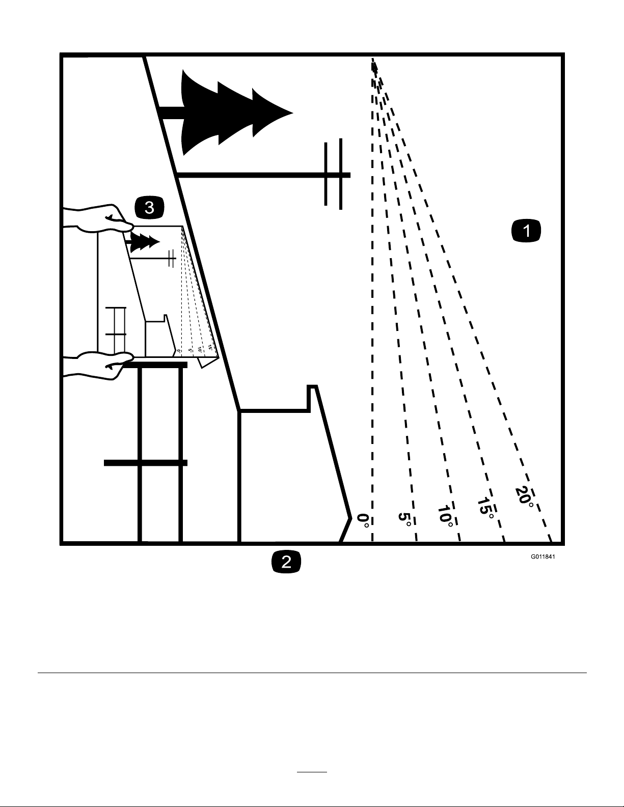
SlopeIndicator
Figure3
1.Themaximumslopeyoucansafelyoperatethemachineonis10°.Usetheslopeindicatortodeterminethedegreeofslopeof
hillsbeforeoperating.Donotoperatethismachineonaslopegreaterthan10°.Foldalongtheappropriatelinetomatchthe
recommendedslope.
2.Alignthisedgewithaverticalsurface,atree,building,fencepole,etc.
3.Exampleofhowtocompareslopewithfoldededge.
4
g011841
SafetyandInstructionalDecals
Safetydecalsandinstructionsareeasilyvisibletotheoperatorandarelocatednearanyarea
ofpotentialdanger.Replaceanydecalthatisdamagedormissing.
112-9028
1.Warning—stayawayfrommovingparts;keepallguardsin
place.
115-2903
decal112-9028
decal115-2903
1.Grease
1.Thrownobjecthazard—Do
notoperatewhenpeople
andpetsareinthearea.
decal116-8140
116-8140
2.Warning—Entanglement
hazard—stayclearofthe
rotatingbroom.
decal133-8062
133-8062
5

decal135-2867
135-2867
1.Warning-ReadtheOperator’sManual.DoNotoperatethis
machineunlessyouaretrained.Stayawayfrommoving
parts;keepallguardsinplace.
4.Warning-Stopengineandremovesparkplugbeforeadjusting,
servicing,orcleaningmachineandattachments.Before
leavingtheoperator’sposition,disengagebroom,traction
drive,andstopengine.Lookbehindandtothesidebefore
changingdirections.DoNotcarrypassengers.
2.Thrownobjecthazard-DoNotoperatewhenpeopleandpets
areinthearea;pickupobjectsthatcouldbethrownbybroom.
5.Warning-Entanglementhazard-stayclearofrotatingbroom.
Broombristleswillmeltorburn-keepawayfromextreme
heatorame.DoNotoperateonanyrooforotherelevated
surface.
3.Warning-Wearhearingprotection.
6.Warning-Operateacrossslopesnotupanddown.Use
extremecautionwhenoperatingonslopes.
144-0316
1.Engagethetraction-controllevertoactivatethetractiondrive.4.Engagetheright-turnlevertoturnright.
2.Engagetheleft-turnlevertoturnleft.5.EngagethePTOlevertoactivatethePTO.
3.Engagethebroom-anglelevertoadjustthebroom.
decal144-0316
6

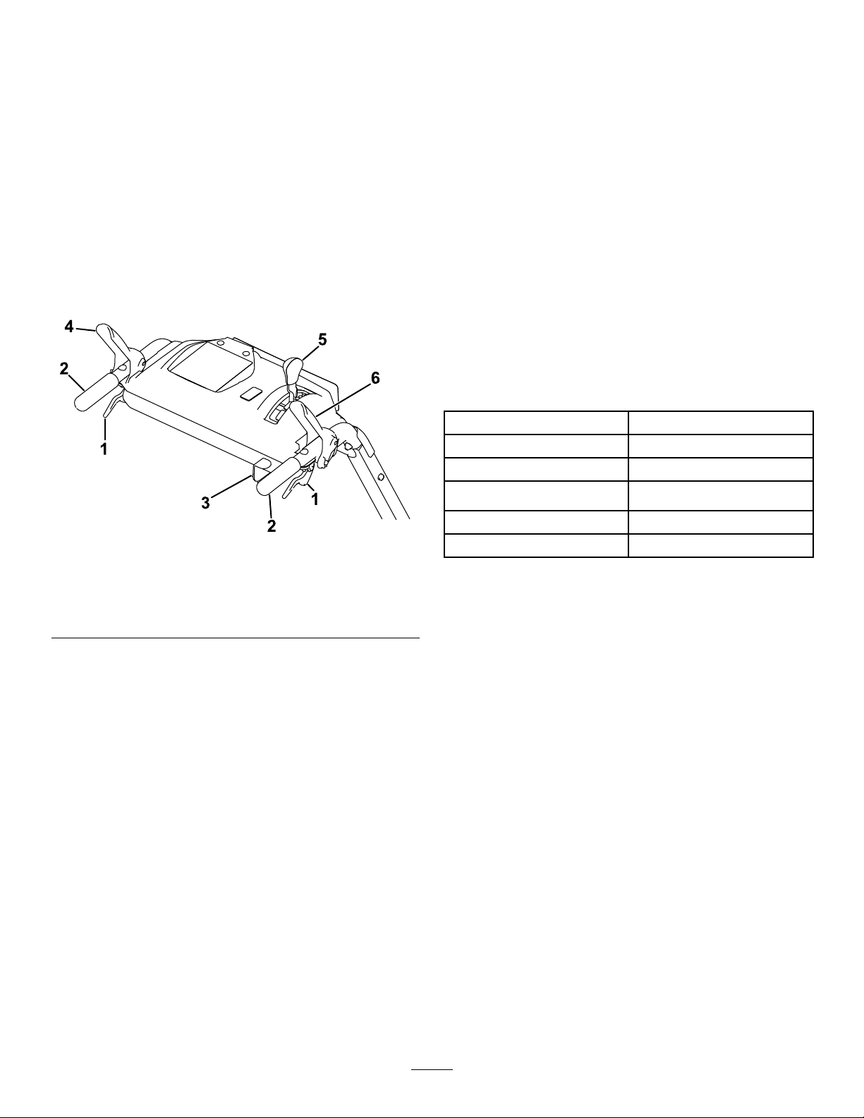
ProductOverview
g326826
Figure5
g325102
Figure4
1.Wheel-clutchlever6.Traction-drivelever
2.Broom-anglelever7.Fuel-tankcap
3.Broom-drivelever8.Broomandhood
4.Speed-selectorlever
5.Handbargrip
9.Broom-height-adjustment
pin
Controls
Determinetheleftandrightsidesofthemachinefrom
thenormaloperatingposition.
ChokeControl
Thechokecontrolisthetopleverlocatedontherear,
leftsideoftheengineabovethefuel-shutoffvalve
(Figure5).
Thechokeisusedtoaidinstartingacoldengine.
MovetheleverlefttotheONpositionforacoldstart.
DonotrunawarmenginewiththechokeintheON
position.
1.Chokecontrol
2.Fuel-shutoffvalve5.EngineOn/Offswitch
3.Throttlecontrol
4.Recoil-starthandle
Fuel-ShutoffValve
Usethefuel-shutoffvalvetoshutoffthefuelwhen
youwillnotusethemachineforafewdays,parkthe
machineinsideabuilding,ortransportthemachineto
andfromthejobsite(Figure5).
Movethelevertothelefttoshutoffthefuel.Movethe
levertotherighttoturnonthefuel.
ThrottleControl
Thethrottlecontrolislocatedontherear,rightsideof
theengineandbelowthefueltank(Figure5).
Thethrottleisusedtocontrolenginespeed.Moving
thethrottlecontroltotheleftincreasestheengine
speed,andmovingitrightdecreasestheengine
speed.
EngineOn/OffSwitch
Locatedontherightsideoftheengine(Figure5).
RotatetheswitchclockwisetotheONposition
beforestartingtheengine.Rotatetheswitch
counterclockwisetotheOFFpositiontoshotoffthe
engine.
7
Wheel-ClutchLevers
Speed-SelectorLever
Thewheel-clutchleversarelocatedbelowtheright
andlefthandles.
Thewheelclutchleversallowthedrivetomomentarily
disengageto1orbothwheelswiththetraction-drive
leversqueezed.Thisallowsforeasierturningand
maneuveringthemachine(Figure6).
Note:Squeezingbothwheelclutchlevers
simultaneouslydisengagesthedrivetobothwheels
(free-wheeling).Thisenablesyoutomanuallymove
themachinebackwardwithoutstoppingtoshiftitinto
areversegear.Italsoallowsyoutomaneuverand
transportthemachinemoreeasilywhentheengine
isnotrunning.
Thespeed-selectionleverislocatedonthemain
consolepanel(Figure6).
Thespeedselectorhas6forwardand2reverse
settings.T ochangespeeds,releasethetraction-drive
lever,andshiftthespeed-selectorlevertothedesired
setting.Theleverlocksinanotchateachspeed
setting.
Broom-AngleLever
Thebroom-angleleverislocatedattherighthandle
(Figure6).
Thebroom-anglelevercontrolstheanglelock.The
broomanglecanbelockedinto3positions:straight
ahead,orangledtotheleftorright19°.
Specications
Width
Length
Height
Weight
118cm(46.5inches)
185.5cm(73inches)
105.5cm(41.5inches)
151kg(333lb)
Figure6
1.Wheel-clutchlever4.Traction-drivelever
2.Handle
3.Broom-anglelever6.Broom-drivelever
5.Speed-selectorlever
Broom-DriveLever
Thebroom-driveleverislocatedabovetheright
handle(Figure6).
Toengagethebroom,squeezethelevertothehandle.
Todisengagethebroom,releasetherightlever.
Traction-DriveLever
Thetraction-driveleverislocatedabovetheleft
handle(Figure6).
Thetraction-drivelevercontrolstheforwardand
reversemotionofthemachine.T oengagethetraction
drive,squeezethelevertothehandle.
g325105
Enginespeed(noload)
Fueltankcapacity
Fullspeed:3600±100rpm
4.1L(1.0USgallon)
Attachments/Accessories
AselectionofT oroapprovedattachmentsand
accessoriesisavailableforusewiththemachine
toenhanceandexpanditscapabilities.Contact
yourAuthorizedServiceDealerorauthorizedT oro
distributororgotowww.Toro.comforalistofall
approvedattachmentsandaccessories.
Toensureoptimumperformanceandcontinuedsafety
certicationofthemachine,useonlygenuineT oro
replacementpartsandaccessories.Replacement
partsandaccessoriesmadebyothermanufacturers
couldbedangerous,andsuchusecouldvoidthe
productwarranty.
Note:Holdingdownthetraction-driveleveragainst
thehandleengagesthetractiondrivetobothwheels.
8
Operation
BeforeOperation
BeforeOperationSafety
GeneralSafety
•Wearappropriateclothing,includingeye
protection;longpants;substantial,slip-resistant
footwear;andhearingprotection;alsoweara
respiratorordustmaskindustyconditions.Tie
backlonghair,securelooseclothing,anddonot
wearloosejewelry.
•Thoroughlyinspecttheareawhereyouwillusethe
machine,andremovealldoormats,sleds,boards,
wires,andotherforeignobjects.
•Ifashield,safetydevice,ordecalisdamaged,
illegible,ormissing,repairorreplaceitbefore
beginningoperation.Also,tightenanyloose
fasteners.
FuelSafety
Fuelisextremelyammableandexplosive.Areor
explosionfromfuelcanburnyouandothers.
•Topreventastaticchargefromignitingthefuel,
placethecontainerand/ormachineontheground
beforelling,notinavehicleoronanobject.
•Fillthefueltankoutdoorswhentheengineiscold.
•Replacethefuelcapsecurelyandwipeupspills.
•Donothandlefuelwhensmokingoraroundan
openameorsparks.
•Storefuelinanapprovedfuelcontainer,outofthe
reachofchildren.
•Whenfuelisinthetank,tipthemachineonlyas
directedintheinstructions.
•Ifyouspillfuelonyourclothing,changeyour
clothingimmediately.
FillingtheFuelTank
Useonlyclean,fresh(nomorethan30daysold),fuel
fromareputablesource.
FillthefueltankasshowninFigure7;donotllabove
thebottomofthefueltankneck.
g216203
Figure7
Important:Forbestresults,purchaseonlythe
quantityoffuelthatyouexpecttousein30days.
Otherwise,addfuelstabilizer/conditionertofresh
fuelasdirectedbythefuel-stabilizer/conditioner
manufacturer.
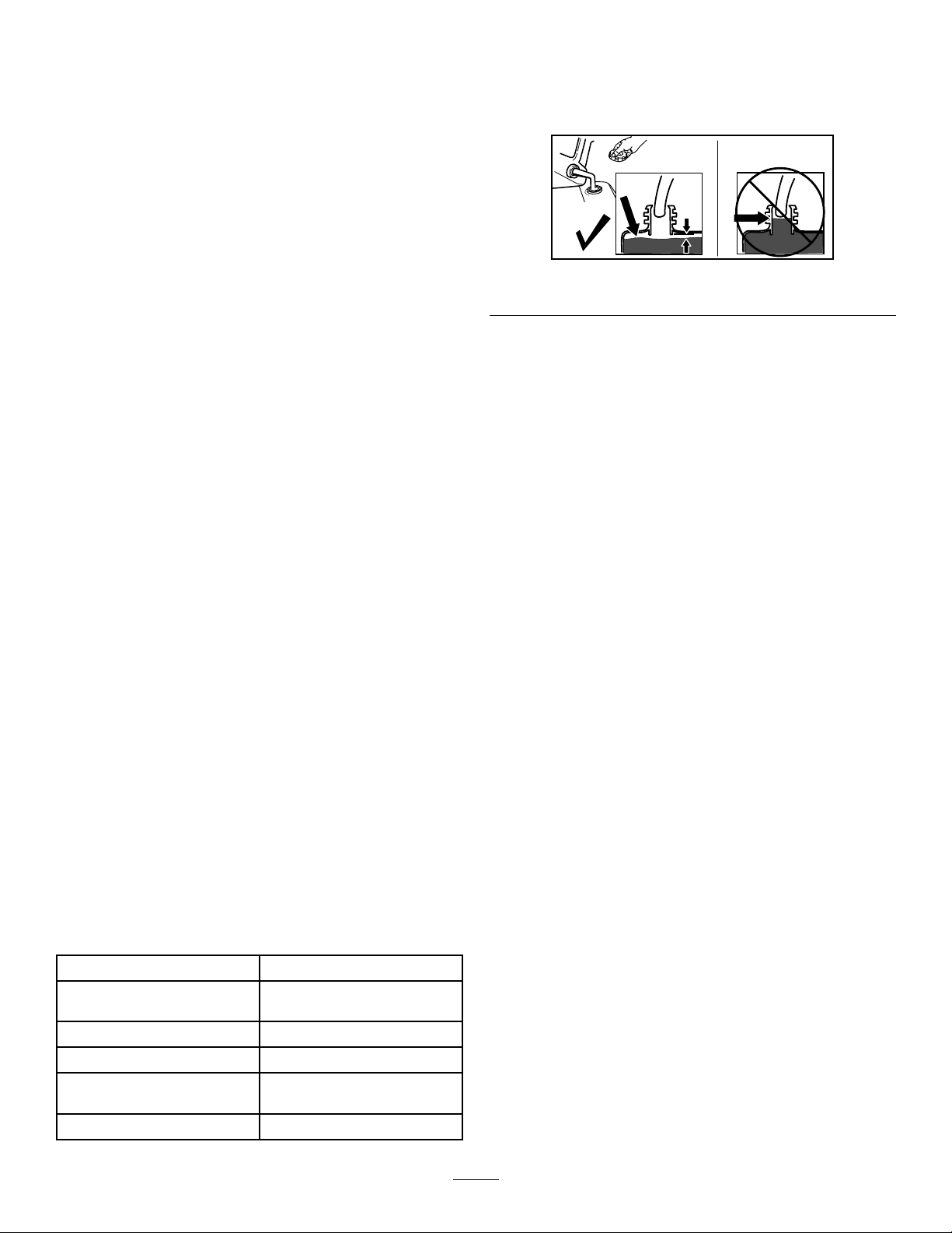
CheckingtheSweeping
Path
Abroomsweepswiththetipsofitsbristles.Whenyou
applytoomuchdownwardpressure,thebroomno
longerusesitstips;thebroomisnowworkingwiththe
sidesofthebristles.Thislimitstheickingactionof
thebristlesandsweepingeffectiveness,decreasing
theservicelifeofthebroom.
1.Drivethemachinetoaat,dustyareaandstop
themachine.
2.Withtheenginerunning,movethethrottle
midwaybetweentheSLOWandFASTpositions.
3.Squeezethebroom-drivecontrol,andallowthe
broomtorotatefor30seconds.
4.Releasethebroom-drivecontrol,shutoffthe
engine,andwaitforallmovingpartstostop.
5.Checktheareasweptbythebroom.The
broom-sweepareashouldequalthefullbroom
widthandamaximumdepthof51to102mm(2
to4inches).
TypeUnleadedgasoline
Minimumoctanerating
Ethanol
MethanolNone
MTBE(methyltertiarybutyl
ether)
OilDonotaddtothefuel
87(US)or91(research
octane;outsidetheUS)
Nomorethan10%byvolume
Lessthan15%byvolume
9
1.51to102mm(2to4
inches)maximumdepth
2.Fullbroomwidth
Figure8
3.Sweptarea
4.Raiseorlowerthecasterwheeltubetoadjust
theareasweptbythebroomasstatedin
CheckingtheSweepingPath(page9).
Note:Selectanyholecombinationthatisin
alignmenttoplaceandlatchtheretainingpin;
matchthesamepositionontheotherside.
5.Forneradjustment,slidetheadjustersleeve1
pinholeupordownonthecasterwheeltube
toadjustthebroomheightin3mm(1/8inch)
increments(Figure9).Repeatsteps3through5
fortheothercasterwheel.
•Toraisethebroomin3mm(1/8inch)
increments,slightlyraisetheadjustersleeve
g017922
andinsertthepinintothenextpinholebelow
thecurrentholeused.
•Tolowerthebroomin3mm(1/8inch)
increments,slightlylowertheadjustersleeve
andinsertthepinintothenextpinhole
abovethecurrentholeused.
6.Ifthebroom-sweepareaistoolarge,toosmall,
oruneven,adjustthebroomheight;referto
AdjustingtheBroomHeight(page10).
AdjustingtheBroomHeight
1.Drivetoaat,dustyareaandstopthemachine.
2.Ensurethatthebroom-driveleverisreleased,
shutofftheengine,andwaitforallmovingparts
tostop.
3.Toadjustthebroomheight,removeandretain
thepinfromtheadjustersleeveandwheeltube
ofthecaster(Figure9).
6.Whenthebroomheightisadjusted,secure
thepinoneachcasterwheel,andcheckthe
broom-sweeparea;refertoCheckingthe
SweepingPath(page9).
DuringOperation
DuringOperationSafety
GeneralSafety
•Staybehindthehandlesandawayfromthe
dischargeopeningwhileoperatingthemachine.
Keepyourface,hands,feet,andanyotherpart
ofyourbodyorclothingawayfrommovingor
rotatingparts.
•Neverdirectthedischargetowardpeopleorareas
wherepropertydamagecanoccur.
•Useyourfullattentionwhileoperatingthe
machine.Donotengageinanyactivitythat
causesdistractions;otherwise,injuryorproperty
damagemayoccur.
1.Caster-wheeltube
2.Positionstoachieve3mm
(1/8inch)increments
Figure9
3.Pin
4.Adjustersleeve
•Donotoperatethemachinewhileill,tired,or
undertheinuenceofalcoholordrugs.
•Exercisecautiontoavoidslippingorfalling,
especiallywhenoperatingthemachineinreverse.
g030413
•Alwaysbesureofyourfooting,andkeeparm
holdonthehandles.Walk;neverrun.
•Donotclearsnow,dirt,orthatchacrossthefaceof
slopes.Exerciseextremecautionwhenchanging
directiononslopes.Donotattempttoclearsteep
slopes.
10
•Donotoperatethemachinenearglassenclosures,
automobiles,windowwells,dropoffs,etc.without
properlyadjustingthebroomdischargeangle.
•Donotoperatethemachinewithoutgoodvisibility
orlight.
•Lookbehindandusecarewhenbackingupthe
machine.
•Exerciseextremecautionwhenoperatingthe
machineonorcrossinggraveldrives,walks,or
roads.Stayalertforhiddenhazardsortrafc.
•Neverattempttomakeanyadjustmentswhile
theengineisrunning,exceptasdirectedinthe
instructions.
•Afterstrikingaforeignobject,shutofftheengine,
andinspectthemachinefordamage.Repairany
damagebeforestartingthemachine.
•Ifthemachinestartstovibrateabnormally,shutoff
theengineandcheckimmediatelyforthecause.
•Donotruntheengineindoors,exceptwhen
startingitandformovingthemachineinoroutof
thebuilding;exhaustfumesaredangerous.
•Donotoverloadthemachinecapacityby
attemptingtoclearsnow,dirt,orthatchattoofast
ofarate.
•Shutofftheenginewheneveryouleavethe
operatingposition,beforeuncloggingthe
broomhousing,andwhenmakinganyrepairs,
adjustments,orinspections.
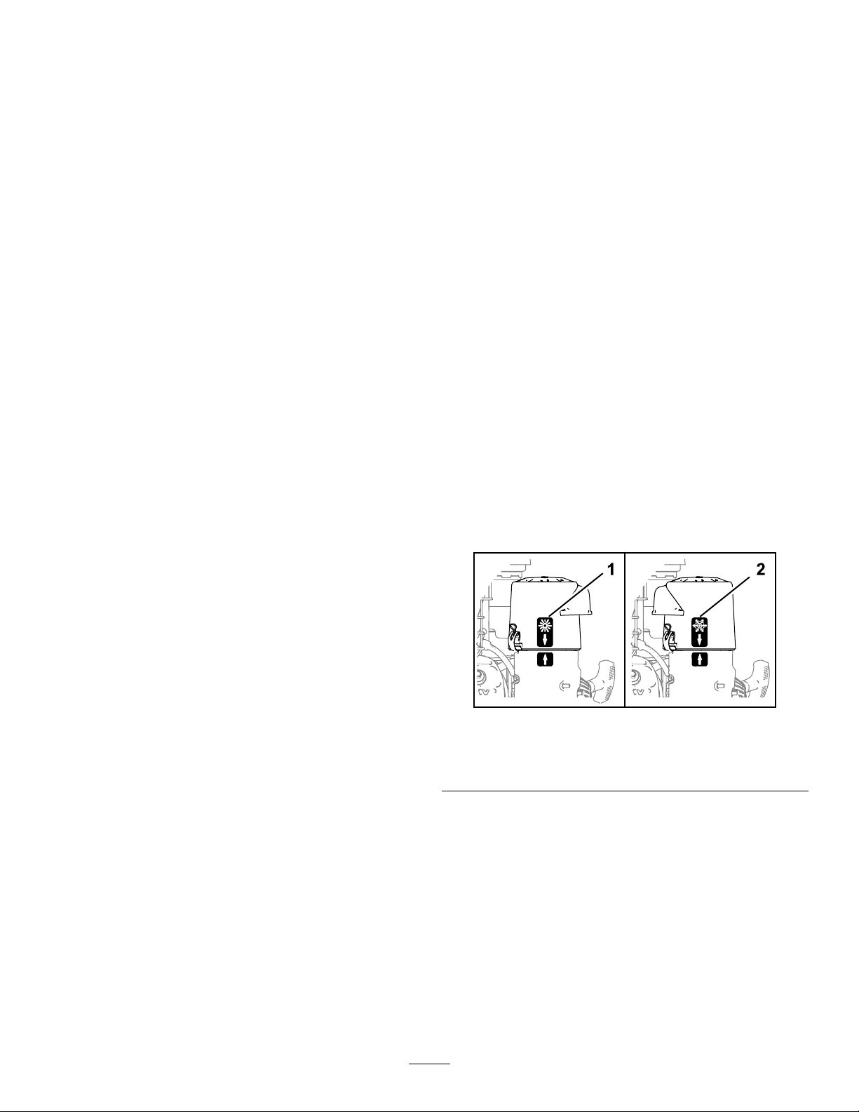
OperatingtheEngine
PositioningtheAir-CleanerCover
forColdorWarmAirTemperature
Important:Runningtheenginewiththe
air-cleanercoverpositionedforcold-weather
operationinnormalconditionscandamagethe
engine.
Theair-cleanercoverhas2positions:thecoldor
normal,ambientairpositions:
Adjusttheair-cleanercoverasfollows:
•Whenoperatinginacoldambientaircondition
(coldairtemperatureandhumidity)—positionthe
air-cleanercoverwithsnowakedecalfacingout
(Figure10).
Note:Usethispositionifyourmachineexhibits
carburetoricing.Symptomsincludetheengine
runsroughatidleorlowspeed,anditdischarges
blackorwhitesmokeintheexhaust.
•Whenoperatinginanormalambientair
condition—positiontheair-cleanercoverwithsun
decalfacingout(Figure10).
Note:Usethispositionifyourmachineisnot
exhibitingcarburetoricing.
•Beforeclearingthebroom,parkthemachine
onlevelground,shutofftheengine,waitfor
allmovingpartstostop,anddisconnectthe
spark-plugwire(s).Sharpobjectscanbecome
entangledinthebristles.Wearglovesanduse
cautionwhencleaningoutthebroomofforeign
objects;donotuseyourbarehands.
•Neveroperatethemachineathightransport
speedsonslipperysurfaces.
•Useonlyattachmentsandaccessoriesapproved
bythemanufacturerofthemachine.
1.Normalambientair
position
g326835
Figure10
2.Coldambientairposition
11

OpeningtheFuel-ShutoffValve
StartingtheEngine
Movethefuel-shutoffvalvelocatedbelowthechoke,
totherighttoturnonfuel(Figure11).
Figure11
1.FUELONposition3.Choke
2.Fuel-shutoffvalve
1.Ontherightsideoftheengine,rotatetheengine
On/OffswitchclockwisetotheONposition
(Figure12).
g325099
g325098
Figure12
1.Recoil-starthandle
2.Throttle
3.Engineswitch(OFF
position)
4.Engineswitch(ON
position)
2.Ontherear,leftsideoftheengine,movethe
chokelevertothelefttotheONposition.On
awarmengine,leavethechokeintheOFF
position(Figure11).
3.PlacethethrottlemidwaybetweentheSLOW
andFASTpositionslocatedonrear,rightsideof
theengine(Figure12).
4.Slowlypulltherecoil-starthandleuntilyoufeel
resistanceandthenstop(Figure12).
5.Allowtheropeoftherecoil-starthandletoretract
andthensharplypullthehandlestraightout.
Note:Allowtheropetoretractslowly.
6.Allowtheenginetowarmupforseveralminutes,
thenmovethechoketowardtheOFFposition
(Figure11).
StoppingtheEngine
1.Releasethebroom-driveleverandthe
traction-drivelever.
2.PlacethethrottlemidwaybetweentheSLOW
andFASTpositions(Figure12).
12
3.Allowtheenginetorunforaminimumof15
seconds,thenturntheengineOn/Offswitchto
theOFFpositiontostoptheengine(Figure12).
4.Waitforallmovingpartstostopbeforeleaving
theoperatingposition.
5.Usethefuel-shutoffvalvetoshutofffuelwhen
youwillnotusethemachineforafewdays,park
themachineinsideabuilding,ortransportthe
machinetoandfromthejobsite(Figure11).
g326524
Figure14
DrivingtheMachine
CAUTION
Ifthetractiondriveisnotproperlyadjusted,
themachinemaymoveinthedirection
oppositeofwhatyouintended,causinginjury
and/orpropertydamage.
Carefullycheckthetractiondriveandadjustit
properly,ifnecessary .
Important:Ifthemachinemoveswhenthe
tractionleverisdisengaged,checkandadjustthe
tractioncable;refertoCheckingtheBroomDrive
Adjustment(page25)andAdjustingtheTraction
Cable(page24),orcontactyourAuthorized
ServiceDealer.
DrivingForward
1.Placethespeedselectorlevertothedesired
forwardposition,makingsurethatitlocksinthe
notch(Figure13).
3.Tostopthetractiondrive,releasethe
traction-drivelever.
4.Usethewheelclutchesleversasfollows:
Note:
•Todrivestraight,squeezethetraction-drive
leverbutdonotsqueezethewheel-clutch
levers(Figure15).
g326528
Figure15
•Toturnleft,squeezethetraction-drivelever
andsqueezetheleftwheel-clutchlever
(Figure16).
Figure13
Note:Ifthegroundspeedistoofast,debrisor
snowwillpileupinfrontofthebroomcausing
thebroomtoplowinsteadofsweep.Thiscan
damagethebristlesandthedriveline.
2.Slowlysqueezethetraction-drivelevertothe
lefthandle(Figure14).
Note:Holddownthetraction-driveleveragainst
thehandletoengagethetractiondriveforboth
wheels.
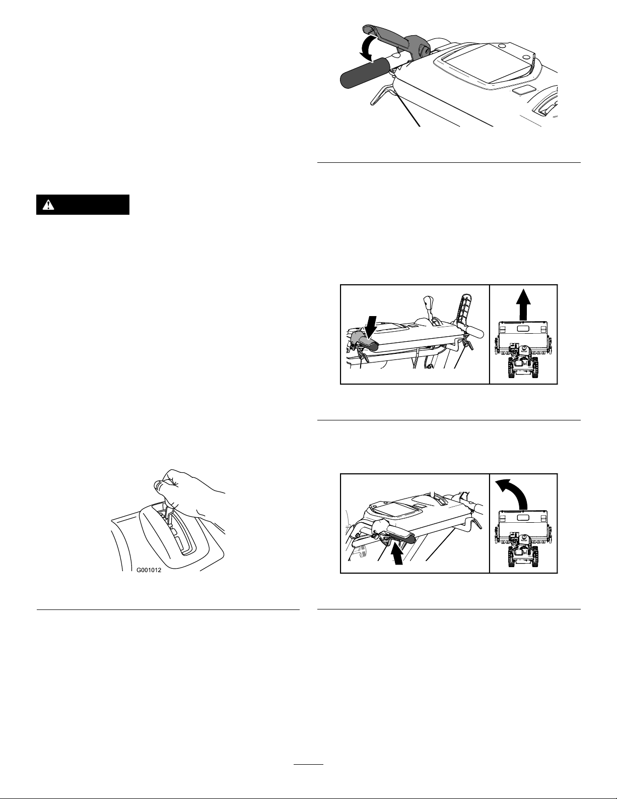
g001012
Figure16
g326521
Note:Whenyoucompletetheturn,release
thewheel-clutchlever.Thetractiondrive
engagesbothwheels.
•Toturnright,squeezethetraction-drivelever
andsqueezetherightwheel-clutchlever
(Figure17).
13

Figure17
Note:Whenyoucompletetheturn,release
thewheel-clutchlever.Thetractiondrive
engagesbothwheels.
•Momentarilysqueezeandreleasetheleft
orrightwheel-clutchlevertomakesteering
adjustmentsandkeepthemachinemoving
inastraightline,especiallyindeepsnow.
5.Toshutoffthetractiondrive,releasethe
traction-drivelever.
DrivingtheMachineRearward
PivotingtheMachinewiththe
EngineShutoff
Squeezebothwheel-clutchleverssimultaneouslyand
pivotthemachine(Figure18).
g326522
1.Placethespeed-selectorleverintothedesired
reverse-speedrange,makingsurethatthe
speedselectorlocksinthenotch.
2.Tomoverearward,engagethetractiondrive
andslowlysqueezethelefttractionlevertothe
handle.
Note:Momentarilysqueezingandreleasingthe
leftorrightwheel-clutchleverallowsforsteering
adjustmentstokeepthemachinegoingina
straightline.
Note:Toturnright,squeezetheright
wheel-clutchlevertowardthehandle.This
disengagesthedrivetotherightwheelwhilethe
leftwheelcontinuesdriving,andthemachine
turnstotheright.
Note:Similarly ,squeezingtheleftwheel-clutch
leverturnsthemachinetotheleft.
Note:Squeezingbothwheel-clutchlevers
simultaneouslydisengagesthedrivetobothwheels.
Thisenablesyoutomovethemachinerearward
withoutstoppingtoshiftitintoareversegear.Italso
allowsyoutomaneuverandtransportthemachine
moreeasilywhentheengineisnotrunning.
g326520
Figure18
OperatingtheBroom
DANGER
Whenthemachineisinoperation,contact
withrotatingormovingpartswillseverely
injurehandsandfeet.
•Beforeadjusting,cleaning,inspecting,
troubleshooting,orrepairingthemachine,
shutofftheengineandwaitforallmoving
partstostop.Disconnectthewirefrom
thesparkplugandkeepitawayfromthe
plugtopreventsomeonefromaccidentally
startingtheengine.
•Staybehindthehandlesandawayfromthe
broomwhileoperatingthemachine.
•Keepface,hands,feet,andanyother
partofyourbodyorclothingawayfrom
concealed,moving,orrotatingparts.
14

WARNING
Contactwitharotatingbroomcanresult
inseriouspersonalinjuryordeathtothe
operatororbystanders.
•Toremoveanobstructionfromthebroom;
refertoClearingaCloggedBroom(page
16).
•Donotoperatethemachineifthebroom
driveleverisnotfunctioningproperly.
ContactyourAuthorizedServiceDealer.
g326523
Figure19
WARNING
Therotatingbroomcanthrowstonesand
otherforeignobjects,causingserious
personalinjurytoyouorbystanders.
•Keeptheworkingareaclearandfreeofall
objectsthatthebroomcouldpickupand
throw.
•Keepallchildrenandpetsawayfromthe
areaofoperation.
CAUTION
Whenthebroomisengaged,itmaydrivethe
machineinthereversedirection.Ifthebroom
heightisadjustedtoolow,themachinemay
movemoreforcefullyinthereversedirection,
causinginjuryand/orpropertydamage.
Carefullycheckthebroomheightandadjust
itproperlyorcontactyourAuthorizedService
Dealer.
•Iftheengineslowsdownunderaloadorthe
wheelsslip,shiftthemachineintoalower
gear.
•Ifthefrontofthemachineridesup,shift
themachineintoalowergear.Ifthefront
continuestorideup,liftthehandles.
4.Tostopthebroom,releasetherightlever.
AdjustingtheBroomSide
Angle
1.Disengagethebroomandshutofftheengine.
2.Waitforallmovingpartstostop.
3.Pushtheleverdownwiththethumbofyourright
hand(Figure20).
1.SettheenginethrottletotheFASTposition.
2.Placethespeedselectorleverintothedesired
positionandslowlysqueezethelefthand
tractiondrivelever.
Important:Makesurethatthetractiondrive
isengagedbeforeoperatingthebroom;
otherwise,thebroommaydrivethemachine
inthereversedirection.
3.Engagethebroombyslowlysqueezingtheright
broomlevertothehandle(Figure19).
g326519
Figure20
4.Squeezetheleftwheel-clutchlevertothehandle
(Figure20)andpushthebroomhousingto
followingpositions.
15
•19°totheleft
•Straightahead
ClearingaCloggedBroom
•19°totheright
5.Oncethebroomispositioned,releasethe
broomanglelever.
Important:Ensurethatthebroomlocksinto
placeatoneofthe3positions.
6.Releasetheleftwheel-clutchlever.
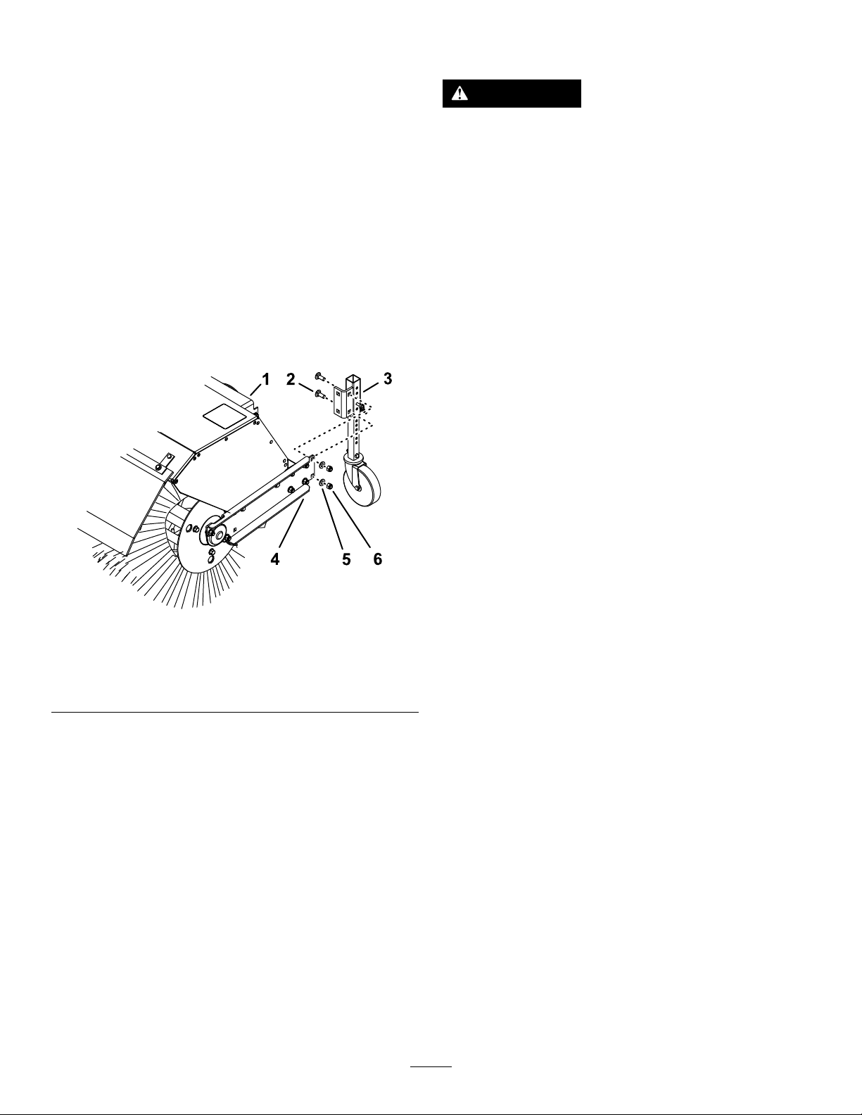
UsingtheAlternateCaster
Location
Whenworkinginsnow,movethecastersfromthe
frontofthebroomarmtothebackthebroomhood
(Figure21).
WARNING
Therotatingbroomcouldcauseserious
injury.
Shutofftheengineandallowallrotatingparts
tostopbeforecleaningthebroom.
•Ifthebroombecomesclogged,stayinthe
operatingpositionandreleasethetraction-drive
lever.Whileengagingthebroom,pushdownon
thehandlestoraisethefrontofthemachinea
fewcentimeters(inches)offthepavement.Then
liftthehandlesquicklytobumpthefrontofthe
machineonthepavement.Repeatifnecessary.
•Ifyoucannotunclogthebroombybumpingthe
frontofthemachine,dothefollowing:
–Parkthemachineonlevelground.shutoffthe
engine,waitforallmovingpartstostop,and
disconnectthespark-plugwire.
–Sharpobjectscanbecomeentangledin
bristles.Useglovesandcautionwhen
removingforeignobjectsfromthebroom;do
notuseyourhands.
Figure21
1.Broomhood4.Broomarm
2.Carriagebolt
3.Casterbracket
1.Supportthebroom.
2.Removethe2locknuts,2washers,and2
carriagebolts(Figure21)thatsecurethecaster
brackettothebroomarm.
3.Atthebackofthebroomhood,aligntheholesin
thecasterbracketwiththeholesontheinboard
sideofthebroomarm(Figure21).
4.Securethecasterbrackettothebroomarmwith
the2locknuts,2washers,and2carriagebolts
(Figure21).
5.Washer
6.Locknut
AfterOperation
g326877
AfterOperationSafety
GeneralSafety
•Neverstorethemachinewithfuelinthefuel
tankinsideabuildingwhereignitionsourcesare
present,suchashotwaterheaters,spaceheaters,
orclothesdryers.Allowtheenginetocoolbefore
storingthemachineinanyenclosure.
•Whenstoringthemachineformorethan30
days,refertotheStoragesectionforimportant
information.
•Whenoperatinginsnowyconditions,runthe
machineforafewminutesafterremovingsnowto
preventfreeze-upofthebroomandhousing.
•Whencleaning,repairing,orinspectingthe
machine,ensurethattherotarybroomandall
movingpartshavestopped.Disconnectthe
spark-plugwireandkeepitawayfromtheplugto
preventaccidentalstarting.
•Disengagethepowertotherotarybroomwhen
transportingorstoringthemachine.
16

PreventingFreeze-upafter
Use
•Insnowyandcoldconditions,somecontrolsand
movingpartsmayfreeze.Donotuseexcessive
forcewhentryingtooperatefrozencontrols.Ifyou
havedifcultyoperatinganycontrolorpart,start
theengineandletitrunforafewminutes.
•Afterusingthemachine,lettheenginerunfora
fewminutestopreventmovingpartsfromfreezing.
Engagethebroomtoclearanyremainingsnow
frominsidethehousing.Shutofftheengineand
waitforallmovingpartstostop,anddisconnect
thespark-plugwire.Removeallice,snow,orother
debrisfromthemachine.
•Connectthespark-plugwire.Withtheengine
switchintheOFFposition,pulltherecoil-starter
handleseveraltimestopreventtherecoilstarter
fromfreezingup.
TransportingtheMachine
WARNING
Usingrampsthatarenotstrongenoughor
properlysupportedtoloadthemachineonto
thetransportvehiclecouldbedangerous.The
rampscouldcollapse,causingthemachineto
fall,whichcouldcauseinjury.
•Useproperrampsthataresecuredtothe
truckortrailer.
•Keepyourfeetandlegsoutfromunderthe
machinewhenloadingandunloading.
PreparingtoTransportthe
Machine
Performthefollowingbeforetransportingthemachine:
•Closethefuel-shutoffvalve.
•Useaheavy-dutytrailertotransportthemachine.
Placethemachineineitheraforwardorreverse
gear,thenblockthewheels.
•Securelyfastenthemachinetothetrailerwith
straps,chains,cables,orropes.
•Ensurethatthetrailerhasallthenecessary
lightingandmarkingasrequiredbylaw.
17

Maintenance
Note:Determinetheleftandrightsidesofthemachinefromthenormaloperatingposition.
RecommendedMaintenanceSchedule(s)
MaintenanceService
Interval
Aftertherst2hours
Aftertherst5hours
Beforeeachuseordaily
Every50hours
Every100hours
Every200hours
Every300hours
Yearly
Yearlyorbeforestorage
MaintenanceProcedure
•Checkthetractioncableadjustmentandcorrectitifnecessary .
•Checkthebroomdriveadjustmentandcorrectitifnecessary .
•Changetheengineoil.
•Checktheengineoillevel.
•Checkthebroom-shaftshearpin.
•Checkforloosehardware.
•Cleanthefoampre-cleaner(morefrequentlyindustyconditions).
•Checkthetireairpressure.
•Checktheconditionofthebelts.
•Lubricatethebroom-angle-lockpin.
•Changetheengineoil(morefrequentlyinsevereconditions).
•Checkthesparkplug.
•Replacethefoampre-cleaner.
•Replacethepaperairlter(morefrequentlyindustyconditions).
•Lubricatethehexshaft.
•Checkthetractioncableadjustmentandcorrectitifnecessary .
•Checkthebroomdriveadjustmentandcorrectitifnecessary .
•Drainthefuelsystemandruntheengineoutthefuelattheendoftheoperating
season.
•Checkthetireairpressure.
Important:Refertoyourengineowner'smanualforadditionalmaintenanceprocedures.Forengine
adjustments,repairs,orwarrantyservicenotcoveredinthismanual,contacttheauthorizedengine
servicedealer.
MaintenanceSafety
Readthefollowingsafetyprecautionsbefore
performinganymaintenanceonthemachine:
•Beforeservicing,adjusting,orcleaningthe
machine,shutofftheengineandwaitforall
movingpartstostop.Ifmajorrepairsareever
needed,contactyourAuthorizedServiceDealer.
PreparingforMaintenance
1.Movethemachinetoalevelsurface.
2.Shutofftheengineandallowittocool.
3.Disconnectthespark-plugwirefromthespark
plugandkeepthewireawayfromtheplug,to
preventaccidentalstarting(Figure22).
•Alwaysweareyeprotectionwhileperformingan
adjustmentorrepairtoprotectyoureyesfrom
foreignobjectsthatthemachinemaythrow.
•Checkallfastenersatfrequentintervalsforproper
tightnesstoensurethatthemachineisinsafe
workingcondition.
•Donotchangethegovernorsettingsontheengine.
•PurchaseonlygenuineT ororeplacementparts
andaccessories.
18
1.Spark-plugwire
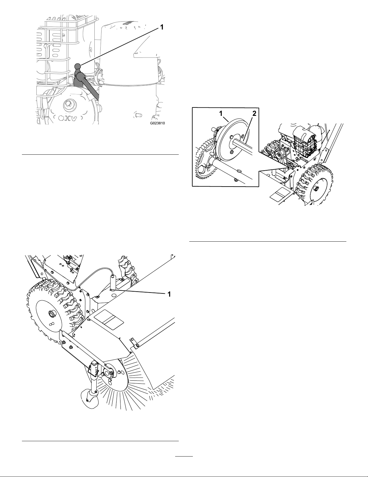
Lubrication
2.Removethebeltcoverandtheengineshield.
3.Movethespeed-selectorlevertotheR2position.
4.Dipalong,clean,small-tippedpaintbrushin
automotiveengineoilandlightlylubricatethe
hexshaft(Figure24).
Important:Donotgetoilontherubber
wheelorthealuminumfriction-driveplateas
thetractiondrivewillslip(Figure24).
Note:Rockthemachineforwardandrearward
torotatethehexshaft.
g023810
Figure22
LubricatingtheBroom-Angle-Lock
PinandtheHexShaft
ServiceInterval:Every100hours
Yearly
1.Lubricatethebroom-angle-lockpinttingwith
No.2lithiumgrease(Figure23).
Figure24
1.Aluminumfriction-drive
plate
5.Movethespeedselectorlevertoposition6.
6.Lubricatetheotherendofthehexshaft.
7.Movethespeedselectorleverforwardand
rearwardafewtimes.
8.Installthebeltcoverandtheengineshield.
2.Hexshaft
EngineMaintenance
ServicingtheAirCleaner
ServiceInterval:Every50hours—Cleanthefoam
pre-cleaner(morefrequentlyin
dustyconditions).
Every200hours—Replacethefoam
pre-cleaner.
g325104
1.Broom-angle-lockpin
Figure23
Every300hours—Replacethepaperairlter
(morefrequentlyindustyconditions).
Important:Donotoperatetheenginewithoutthe
g325097
airlterassembly;extremeenginedamagemay
occur.
1.Releasethelatchesonthecoverfortheair
cleaner.
19
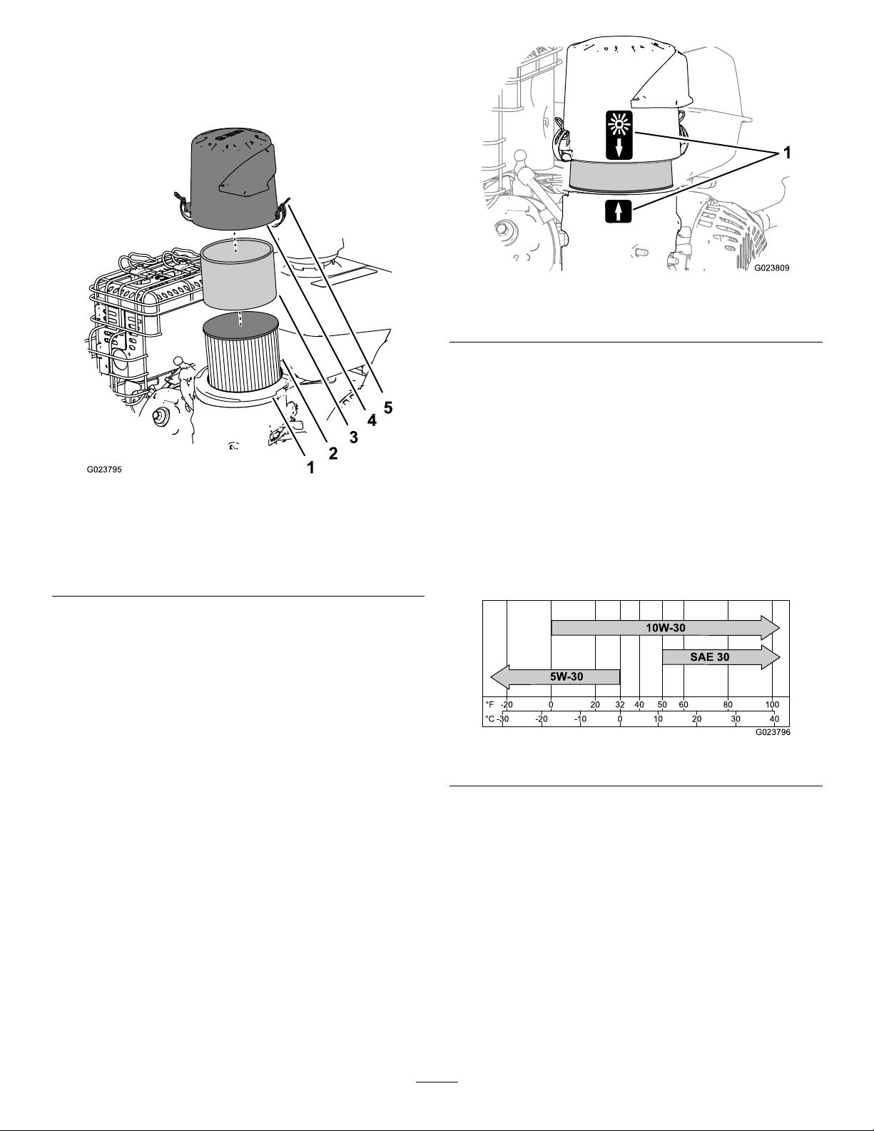
2.Removethecoverandcleanitthoroughly
(Figure25).
Note:Becarefultopreventdirtanddebrisfrom
fallingintothebase.
Figure25
1.Air-lterbase4.Cover
2.Paperairlter
3.Foampre-cleaner
5.Latchontheair-cleaner
cover(2)
g023809
Figure26
1.Alignment-arrowdecal(normalambientairpositionshown)
9.Securetheair-ltercovertothebasewiththe
latches.
CheckingtheEngine-OilLevel
ServiceInterval:Beforeeachuseordaily
g023795
EngineOilType:T oro4–CyclePremiumEngineOil
Usehigh-qualitydetergentoils(includingsynthetic)
ofAPI(AmericanPetroleumInstitute)serviceclass
SJorhigher.Selecttheviscositybasedontheair
temperatureattimeofoperationasshowninthetable
below.
3.Removethefoampre-cleaner,washitwitha
milddetergentandwater,andthenblotitdry
(Figure25).
4.Removeandinspectthepaperairlter(Figure
25);discarditifitisexcessivelydirty.
Important:Donottrytocleanapaperlter.
5.Wipedirtawayfromthebaseandthecoverwith
amoistrag.
Note:Becarefultopreventdirtanddebrisfrom
enteringtheairductleadingtothecarburetor.
6.Installthefoampre-cleanerontothepaperair
lter(Figure25).
Note:Useanewpaperairlterifyoudiscarded
theoldone.
7.Installtheairlterassemblytotheair-lterbase
(Figure25).
8.Alignthearrowdecalontheair-cleanercover
andthearrowdecalonthebase(Figure26).
g023796
Figure27
Checktheoillevelwhentheengineiscold.
1.Cleantheareaaroundthedipstick.
2.Removethedipstickandreadtheoillevel
(Figure28).
20

Figure28
6.Insertthedipstickintothellerneckandtighten
thedipstickbyhand.
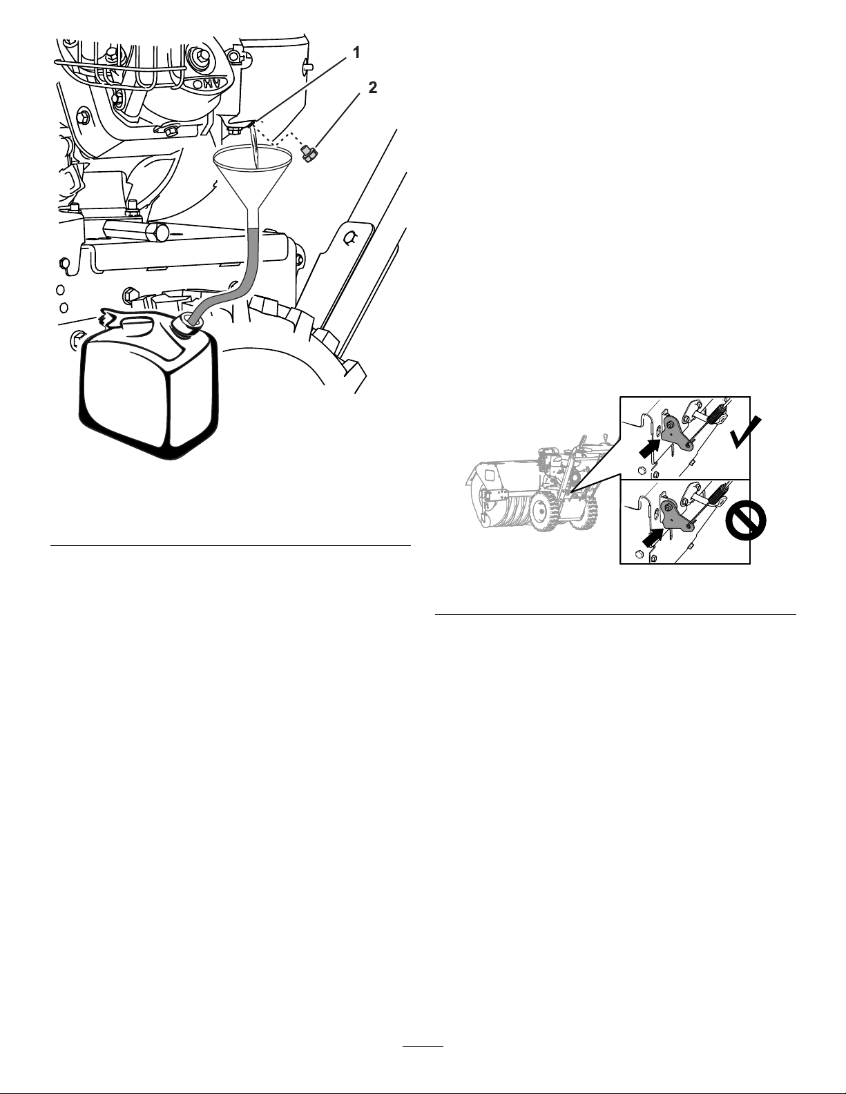
ChangingtheEngineOil
ServiceInterval:Aftertherst5hours
Every100hours(morefrequentlyinsevere
conditions).
Oilcapacity:0.60L(0.63qt)
Note:Draintheengineoilwhiletheengineiswarm.
1.Placeapanunderdrainttingandremovethe
oil-draincap(Figure29).
g023794
1.Fillerneck2.Dipstick
3.Removethedipstickandwipeofftheoilwitha
cleanrag.
4.Insertthedipstickintothellerneck,restiton
theoilllerneck,andturnitcounterclockwise
untilthecapdropsdowntolowestpointofthe
threadleads.
Note:Donotthreadthecapontothetube.
5.Removedipstickandcheckoillevel.
Note:Donotoperatetheenginewiththeoil
levelbelowtheAddmarkorabovetheFullmark
onthedipstick.
Note:Theoillevelshouldbeattopofthe
indicatoronthedipstick(Figure28).
•Iftheoillevelislow,performthefollowing:
A.Pourthespeciedoilintothellerneck
(Figure28).
Note:Donotoverlltheenginewithoil.
B.Repeatsteps3through5.
•Iftheoillevelishigh,preformthefollowing:
A.Removethecapfromthedraintting.
B.Draintheoiluntiltheoillevelisatthetop
oftheindicatorondipstick;refertosteps
1ofChangingtheEngineOil(page21).
C.Installthecapontothedraintting;refer
tostep2ofChangingtheEngineOil
(page21).
Figure29
1.Draintting
2.Cap
3.Drainpan
2.Allowtheoiltodrainandtheninstalltheoil-drain
cap.
3.Cleanaroundthellerneckandremovethe
dipstick.
4.Filltothespeciedcapacitywiththespeciedoil
andreplacethedipstick;refertoCheckingthe
Engine-OilLevel(page20).
Note:Donotoverlltheenginewithoil.
5.Wipeupanyspilledoil.
6.Starttheengineandcheckforleaks.
7.Shutofftheengineandchecktheoillevel;refer
toCheckingtheEngine-OilLevel(page20).
CheckingtheSparkPlug
ServiceInterval:Every100hours
Sparkplugtype:Champion®RC12YC,Kohler®12
13202-S,orKohler2513214-S(RFIcompliant)
g32511 1
21
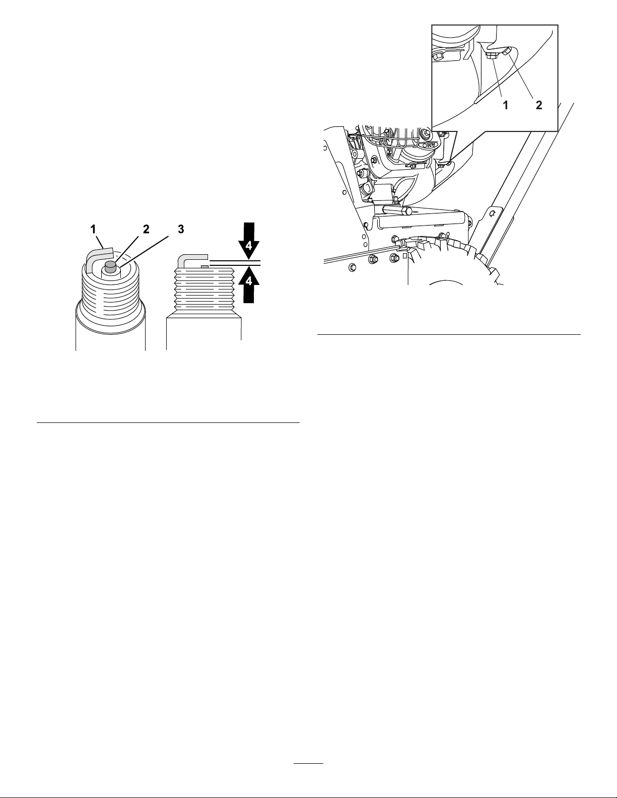
Spark-pluggap:0.76mm(0.030inch)
1.Disconnectthespark-plugwirefromtheterminal
ofthesparkplug(Figure22).
2.Cleantheareaaroundthebaseofthespark
plug.
3.Removethesparkplugfromthecylinderhead
byrotatingtheplugcounterclockwise.
4.Examinetheplugforwearanddamage(Figure
30).
Important:Replaceacracked,fouled,or
dirtysparkplug.Donotcleantheelectrodes,
becausegritenteringthecylindercan
damagetheengine.
g325109
Figure31
1.Bowl-retainingscrew2.Drainbolt
Figure30
1.Groundelectrode
2.Centerelectrode4.Spark-pluggap0.76mm
3.Insulator
(0.030inch)
5.Checkthespark-pluggapwithawiregauge
(Figure30).
Note:Ifnecessary ,adjustthegapto0.76mm
(0.030inch)bycarefullybendingtheground
electrode.
6.Installthesparkplugbythreadingitintothe
cylinderhead,andtorquetheplugto20N∙m(14
lb-ft).
7.Connectthespark-plugwiretotheterminalof
thesparkplug.
FuelSystemMaintenance
DrainingtheFuelSystem
g326888
2.Aligntheequipmentthatyouwillusetocollect
thefuelbeneaththedrainscrew.
3.Removethedrainscrewfromthecarburetor
andallowthefueltodrainfromthefueltankand
thecarburetor.
Note:Donotremovethebowl-retainingscrew
fromcarburetor.
ServiceInterval:Yearlyorbeforestorage
1.Locatethedrainboltthatisinthesideportof
thecarburetorbowl(Figure31).
22
CheckingtheTractionCable
Adjustment
ServiceInterval:Aftertherst2hours—Check
thetractioncableadjustmentand
correctitifnecessary .
Yearly—Checkthetractioncableadjustment
andcorrectitifnecessary.
Important:Ifthemachinedoesnotdriveinthe
forwardorreversespeedsoritdriveswhenyou
releasethetractionlever,adjustthetractioncable;
refertoAdjustingtheTractionCable(page24).
1.Disengagethetractionlevel.
2.Checktheclearancebetweenthebottomofthe
traction-cablebracketandthetopplateofthe
machine(Figure33).
Note:Thetraction-cablebracketshouldtouch
thetopplate.
Figure32
1.Sideportofthecarburetor
bowl
4.Installthedrainboltintothesideportofthe
carburetor.
5.Starttheengineandrunituntilitrunsoutoffuel.
2.Drainbolt
DriveSystemMaintenance
CheckingtheTireAirPressure
ServiceInterval:Every50hours
Yearlyorbeforestorage
1.Shutofftheengine,waitforallmovingparts
tostop,andleaveengineswitchintheOFF
position.
2.Measurethetireairpressureinthedrivetires.
Important:Thetireairpressureshould
measure117to138kPa(17to20psi).
g325110
g326108
Figure33
3.Ifthetraction-cablebracketdoesnottouch
thetopplate,adjustthetractioncable;referto
AdjustingtheTractionCable(page24).
3.Addairtoorremoveairfromthedrivetiresuntil
youmeasureto117to138kPa(17to20psi).
23
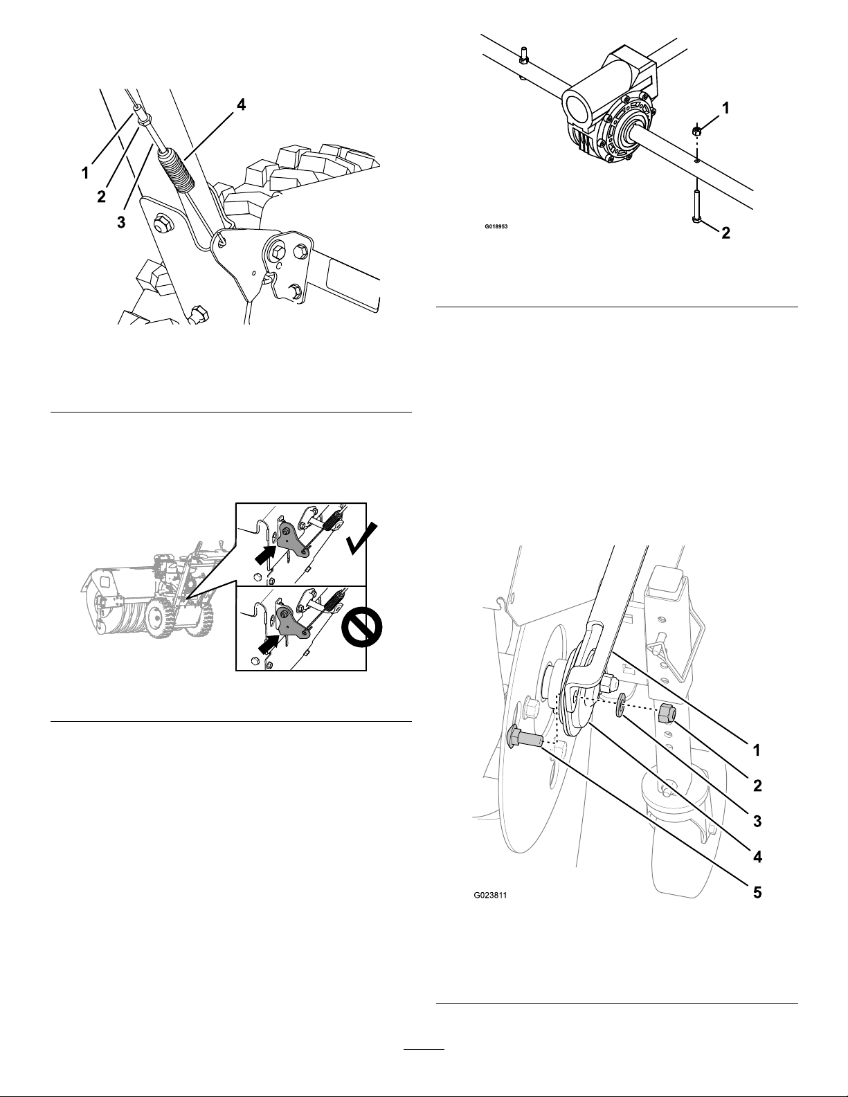
AdjustingtheTractionCable
1.Loosenthejamnut(Figure34).
g019073
Figure36
Figure34
1.Adjustertube
2.Jamnut
3.Spring-tensionadjuster
4.Spring
2.Rotatethespring-tensionadjusteruntilthecable
istaught(Figure34)andthebottomofthe
brackettouchesthetopplateofthemachine
(Figure35).
Figure35
1.Nut
g325108
4.Iftheshearpinisdamaged,removethepin,
2.Shearpin
replaceit,andsecuretheitwithanut.
ReplacingWornorDamaged
BroomSegments
ServiceInterval:Asrequired.
1.Raisethebroombysettingthecasterpositions.
2.Onbothsidesofthemachine,removeandretain
thecarriagebolts,washers,andlocknutsthat
securetheendbearingstothebroomsupport.
g326108
3.Tightenthejamnut(Figure34).
BroomMaintenance
CheckingtheBroom-ShaftShear
Pin
ServiceInterval:Beforeeachuseordaily
1.Movethemachinetoalevelsurface.
2.Shutofftheengine,waitforallmovingpartsto
stop,anddisconnectthespark-plugwire.
3.Checktheshearpinlocatedonthebroomshaft
oneithersideofthegearbox.
1.Broomsupport4.Endbearing
2.Locknut
3.Washer
24
g023811
Figure37
5.Carriagebolt

3.Manuallypullthepowerunitrearwardtoremove
thebroomassemblyfromthemachine.
4.Supportthesplineshaftoneithersideofthe
gearbox.
5.Standthebroomcoreassemblyonendsothat
theendretainerplatefacesupward(Figure38).
Figure38
CheckingtheBroomDrive
Adjustment
ServiceInterval:Aftertherst2hours—Checkthe
broomdriveadjustmentandcorrect
itifnecessary.
Yearly—Checkthebroomdriveadjustmentand
correctitifnecessary.
1.Removethebeltcover;refertoRemovingthe
BeltCover(page26).
2.Withthebroomdriveleverdisengaged,ensure
thatthegapbetweenthebroomclutcharmand
theframeofthemachineis1.5mm(1/16inch)
asshowninFigure39.
Important:Ifthegapbetweenthebroom
clutcharmandtheframeistoosmallortoo
large,adjustthebroomdrivecable;referto
AdjustingtheBroomDriveCable(page26).
g326889
1.Hardware
2.End-retainerplate
3.Broomsegment
4.Supportshaft
5.Alignmentngers
6.Removeandretainthehardwarefromthe
end-retainerplate(Figure38).
7.Removethedamagedbroomsegment(s).
8.Installthenewsegment(s)bystaggeringthe
metalringalignmentngersasshowninFigure
38.
Important:Y oumaydamagethebroom
assemblyifyoudonotproperlyinstallthe
broomsegments.
9.Installthebroomassemblyontothemachine.
Important:Makesurethatthebearing
setscrewsaretightenedbeforeoperatingthe
broom.
Figure39
1.1.5mm(1/16inch)gap
2.Frame
3.Broomclutcharm
3.Ifthegapbetweenthebroomclutcharmand
theframeis1.5mm(1/16inch),installthebelt
cover;refertoInstallingtheBeltCover(page
26).
g326890
25

AdjustingtheBroomDriveCable
1.Loosenthejamnut(Figure40).
Figure40
BeltMaintenance
RemovingtheBeltCover
1.Loosenthe2ange-headscrewsthatsecure
thebeltcovertothemachine(Figure42).
g325107
1.Adjustertube
2.Jamnut
3.Spring-tensionadjuster
4.Spring
2.Rotatethespring-tensionadjusteruntilyou
measurea1.5mm(1/16inch)gapbetweenthe
frameandthebroomclutcharm(Figure40and
Figure41).
Figure41
g325103
Figure42
1.Screw
2.Beltcover
2.Removethecoverfromthemachine.
InstallingtheBeltCover
1.Aligntheslotsinthebeltcoverwiththe2
ange-headscrews(Figure43).
g326890
1.1.5mm(1/16inch)gap
2.Frame
3.Broomclutcharm
3.Tightenthejamnut(Figure40).
4.Installthebeltcover;refertoInstallingtheBelt
Cover(page26).
Important:Ifthebroomcableisproperlyadjusted
butaproblemremains,contactyourAuthorized
ServiceDealer.
g325103
Figure43
2.Assemblethebeltcoverontothemachine
(Figure43).
3.Tightentheange-headscrews.
26
CheckingtheConditionofthe
Belts
ServiceInterval:Every50hours
1.Removethebeltcover;refertoRemovingthe
BeltCover(page26).
2.Checkthe2beltsfordamageorwear.
Note:Replacedamagedorexcessivelyworn
belt(s);refertoReplacingtheBroomDriveBelt
(page27)andReplacingtheTractionBelt(page
28).
3.Installthebeltcover;refertoInstallingtheBelt
Cover(page26).
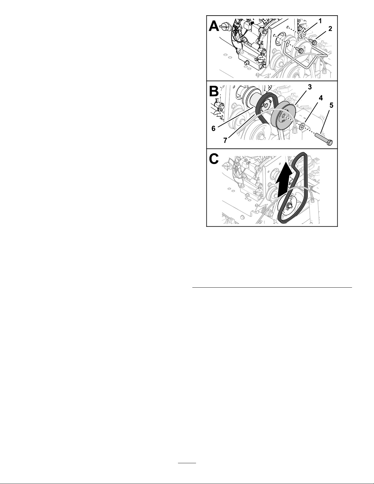
ReplacingtheBroomDriveBelt
RemovingtheBroom-DriveBelt
1.Parkthemachineonalevelsurface,shutoffthe
engine,andwaitforallmovingpartstostop.
2.Removethebeltcover;refertoRemovingthe
BeltCover(page26).
3.Removethe2angecapscrewsthatsecure
thebeltguide,andremovetheguidefromthe
engine(Figure44).
Important:Donotbendthebeltguidewhile
removingit.
g326318
Figure44
1.Beltguide
2.Flangecapscrew6.Pulleyspacer
3.Broom-drivepulley7.Broom-drivebelt96cm
4.Flatwasher
5.Capscrew(3/8x2inches)
(37-1/4inch)
4.Removethecapscrew(3/8x2inches)and
washerthatsecuresthebroom-drivepulleyto
thecrankshaftoftheengine,andremovethe
pulley(Figure44).
Note:Ifnecessary,holdthepulleyspacer
betweenthebroom-drivepulleyandengineto
keepthecrankshaftfromturning.
Youdonotneedtoremovethepulleyspacer
fromthecrankshaft.
5.Slipthebroom-drivebelt96cm(37-1/4inch)off
thedriveshaftpulley ,andremovethebeltfrom
themachine.
27

InstallingtheBroomDriveBelt
Ownerprovidedmaterials:medium-strength
thread-lockingcompound
1.Assemblethewasheroverthecapscrew(3/8x
2inches),andapplyacoatofmedium-strength
thread-lockingcompoundtothethreadsofthe
capscrew.
2.Assemblethebelt96cm(37-1/4inch)intothe
grooveofthedriveshaftpulley(Figure45).
6.Torquethecapscrewto42to52N∙m(31to39
ft-lb).
7.Assemblethebeltguidetotheenginewiththe
2angecapscrew(Figure45).
8.Torquethecapscrewsto23to29N∙m(17to21
ft-lb).
9.Installthebeltcover;refertoInstallingtheBelt
Cover(page26).
ReplacingtheTractionBelt
RemovingtheTractionBelt
1.Drainthefuelsystem;refertoDrainingtheFuel
System(page22).
2.Removethebeltcover;refertoRemovingthe
BeltCover(page26).
3.Removethebroom-drivebelt;refertoRemoving
theBroom-DriveBelt(page27).
4.Removethepulleyspacer,theforwardsheave
half,andtractionbelt87.6cm(34-1/2inches)
fromthecrankshaftoftheengine(Figure46).
Figure45
1.Broom-drivepulleyand
belt96cm(37-1/4inch)
2.Flatwasher5.Beltguide
3.Capscrew(3/8x2inches)
4.Pulleyspacer
6.Flangecapscrew
3.Assemblethebeltintothegrooveofthe
broom-drivepulley(Figure45).
4.Assemblethebroom-drivepulleyontothepulley
spacer(Figure45).
Important:Alignthedrivekeysofthe
spacerwiththeslotsinthepulley.
5.Securethepulleyandspacertothedriveshaft
(Figure45)withthecapscrew(3/8x2inches).
g326388
Figure46
g326353
1.Sheavehalf4.Shaftspacer
2.Tractionbelt87.6cm
(34-1/2inches)
3.Pulleyspacer
5.Crankshaft(engine)
5.Atthebackofthemachine,loosenthe2top
ange-headcapscrew(1/4x5/8inch)that
securetherearcovertothemachine(Figure47).
28

Figure47
1.Flange-headcapscrew
(1/4x5/8inch—loosen)
2.Bottomcover5.Rearcover
3.Flange-headcapscrew
(1/4x5/8inch)
4.Flange(sideplate)
6.Removethe6ange-headcapscrew(1/4x
5/8inch)thatsecurethebottomcovertothe
machine,andremovethecover(Figure47).
7.Slipthetractionbeltbetweenthefrictionwheel
andthetractionpulley ,andremovethebeltfrom
themachine(Figure48).
g326389
g326387
1.Frictionwheel3.Tractionpulley
2.Tractionbelt
Figure49
2.Atthetopofthemachine,alignthetractionbelt
intothegrooveofthetractionpulley,andslipthe
tractionbeltoverthecrankshaftoftheengine
(Figure50).
g326388
Figure50
Figure48
1.Frictionwheel3.Tractionpulley
2.Tractionbelt
InstallingtheTractionBelt
1.Slipthetractionbeltbetweenthefrictionwheel
andthetractionpulley,andintothemachine
(Figure49).
1.Sheavehalf4.Shaftspacer
2.Tractionbelt87.6cm
(34-1/2inches)
3.Pulleyspacer
g326386
5.Crankshaft(engine)
3.Installthebroomdrivebelt;refertoInstallingthe
BroomDriveBelt(page28).
4.Atthebottomofthemachine,aligntheholesin
thebottomcoverwiththeholesintheangesof
theleftandrightsideplates(Figure51).
Note:Ensurethattherearcoveroverlapsthe
bottomcover.
29

Figure51
1.Flange-headcapscrew
(1/4x5/8inch—loosen)
2.Bottomcover5.Rearcover
3.Flange-headcapscrew
(1/4x5/8inch)
4.Flange(sideplate)
Storage
StorageSafety
•Shutofftheengineandwaitforallmovement
tostopbeforeyouleavetheoperator'sposition.
Allowthemachinetocoolbeforeadjusting,
servicing,cleaning,orstoringit.
•Fuelfumesarehighlyammable,explosive,and
dangerousifinhaled.Ifyoustoretheproductinan
areawithanopename,thefuelfumesmayignite
andcauseanexplosion.
g326387
•Neverstorethemachinewithfuelinthefuel
tankinsideabuildingwhereignitionsourcesare
present,suchashotwaterandspaceheaters,
clothingdryers,etc.Allowtheenginetocool
beforestoringthemachineinanyenclosure.
•Disengagethepowertotherotarybroomwhen
transportingorstoringthemachine.
5.Assemblethebottomcovertothemachine
(Figure51)withthe6ange-headcapscrew(1/4
x5/8inch).
6.tightenthe2topange-headcapscrew(1/4
x5/8inch)thatsecuretherearcovertothe
machine(Figure51).
ChassisMaintenance
CheckingforLooseHardware
ServiceInterval:Beforeeachuseordaily
1.Inspectthemachineforanyloosehardware,
missinghardware,oranyotherpossible
problem.
2.Tightenallloosehardwarebeforeoperatingthe
machine.
3.Replaceanymissinghardwarebeforeoperating
themachine.
PreparingtheMachinefor
Storage
PreparingtheFuelSystem
1.Onthelastrefuelingoftheyear,addfuel
stabilizertofreshfuel.
2.Addthetreatedfueltothemachineandrunthe
enginefor10-minutes.
3.Drainthefuelfromthefuelsystem;referto
DrainingtheFuelSystem(page22).
Note:Donotstorestabilizedfuelformorethan
90days.
4.Runthemachineuntiltheenginestopsfrom
runningoutoffuel.
5.Primetheengineandstartitagain.
6.Allowtheenginetorununtilitstops.
7.Allowittocool.
PreparingtheEngine
1.Disconnectthespark-plugwire.
2.Removethesparkplug,add30ml(1oz)of
engineoilthroughthespark-plughole,andpull
thestarterropeslowlyseveraltimes.
3.Looselyinstallthesparkplug.
PreparingtheChassis
1.Supporttheframe,sothebristlesarenot
touchingtheground.
Important:Thebristleswillbecome
deformedandthebroomwillbeoutof
30

alignmentifthebristlesaretouchingthe
groundforanextendedperiod.
2.Thoroughlycleanthebroomandensurethatitis
freeofallcausticchemicalsand/orresidue.
3.Cleanthemachinethoroughly.
4.Touchupchippedsurfaceswithpaintavailable
fromyourAuthorizedServiceDealer.Sand
affectedareasbeforepainting,andusearust
preventativetopreventthemetalpartsfrom
rusting.
5.Tightenallloosescrews,bolts,andlocknuts.
Repairorreplaceanydamagedparts.
6.Coverthemachineandstoreitinaclean,dry
placeoutofthereachofchildren.Allowthe
enginetocoolbeforestoringitinanyenclosure.
Important:Keepthebroomawayfrom
sunlight,weather,andtemperaturechanges
topreventbrittleness.
RemovingtheMachine
fromStorage
1.Removethesparkplugandpulltherecoil-start
handletorapidlyspintheengineandpumpthe
excessoilfromthecylinder.
2.Installthesparkplugbyhandandthentorqueit
to20.4N∙m(15ft-lb).
3.Connectthespark-plugwire.
4.Performtheannualmaintenanceprocedures
asgivenintheRecommendedMaintenance
Schedule;refertoMaintenance(page18).
31

Troubleshooting
Problem
Theenginedoesnotstart,startshard,or
failstokeeprunning.
Theenginelosespower.
PossibleCauseCorrectiveAction
1.Thefueltankisempty.1.Fillthefueltank.
2.Thefuel-shutoffvalveisclosed.2.Openthefuel-shutoffvalve.
3.Thethrottleandchokearenotinthe
correctposition.
4.Thereisdirtinfuelvalve.4.Cleanthefuel-valvescreenandcup.
5.Thefuel-capventisblocked.5.Cleanthefuel-capvent.
6.Dirt,water,orstalefuelisinthefuel
system.
7.Theaircleanerisdirty.
8.Thesparkplugisfaulty.8.Clean,adjustorreplacethesparkplug.
9.Thespark-plugwireisnotconnected.
1.Theengineloadisexcessive.1.Reducethegroundspeedoradjust
2.Theaircleanerisdirty.
3.Theoillevelinthecrankcaseis
incorrect.
4.Thereisdirtinfueltanklter.4.Cleanthefuel-tanklter.
5.Dirt,water,orstalefuelisinthefuel
system.
3.Ensurethatthethrottlecontrolis
midwaybetweentheSlowandFast
positions,andthechokeisintheOn
positionforacoldengineortheOff
positionforawarmengine.
6.Contactanauthorizedengineservice
dealer.
7.Cleanorreplacetheaircleaner
element.
9.Checkthespark-plugwireconnection.
thebroom.
2.Cleanorreplacetheaircleaner
element.
3.Checktheoillevelinthecrankcase.
5.Contactanauthorizedengineservice
dealer.
Thebroomdoesnotcleanthesurface.
Thebroomdoesnotrotate.
Themachinepullsleftorright.
Themachinevibratesabnormally .
1.Thebroomheightisincorrect.1.Adjustthebroomheight.
2.Thetirepressureinthedrivetiresis
notcorrect.
3.Y ouarecleaningtoomuchdebrisat
onetime.
1.Thebroomisclogged.1.Unclogthebroom.
2.Thebroomdriveleverisnotengaged.2.Engagethebroomdrivelever.
3.Thebroomdrivebeltisslipping.3.Adjustorreplacethebelt.
4.Thebeltisbroken.4.Replacethebelt.
5.Theshearpinisbroken.5.Replacetheshearpin.
1.Thetirepressureinthedrivetiresis
notcorrect.
1.Thedrivebeltisworn,looseorbroken.1.Installanewbelt. Themachinedoesnotdrive.
2.Thedrivebeltisoffapulley.
1.Thebroomassemblyislooseor
damaged.
2.Theenginemountingboltsareloose.2.Tightentheengine-mountingbolts.
3.Theenginepulleyoridlerpulleyis
loose.
4.Theenginepulleyisdamaged.
5.Thebeltisdamaged.5.Installanewbelt.
2.Adjustthetirepressureinthedrive
tires.
3.Slowdownandclearsmallerareasof
debris.
1.Adjustthetirepressureinthedrive
tires.
2.Replaceoradjustthebelt.
1.Tightenthehardware,replacethe
broomassembly,orcontactyour
AuthorizedServiceDealer .
3.Tightentheappropriatepulley.
4.ContactyourAuthorizedService
Dealer.
Thebroomdoesnotstopwhenthedrive
leverisreleased.
1.Thebroom-drivebeltisoutof
adjustment.
32
1.Checkthebroom-driveadjustment.

Problem
PossibleCauseCorrectiveAction
Thebroomwearsoutprematurely .1.Y ouareusingtheincorrectbroom
Thespeedselectorisdifculttomoveor
locked.
height.
1.Thehexshaftneedslubrication.1.Lubricatethehexshaft.
1.Adjustthebroomheight.
33

Notes:

CaliforniaProposition65WarningInformation
Whatisthiswarning?
Youmayseeaproductforsalethathasawarninglabellikethefollowing:
WARNING:CancerandReproductiveHarm—www.p65Warnings.ca.gov.
WhatisProp65?
Prop65appliestoanycompanyoperatinginCalifornia,sellingproductsinCalifornia,ormanufacturingproductsthatmaybesoldinorbroughtinto
California.ItmandatesthattheGovernorofCaliforniamaintainandpublishalistofchemicalsknowntocausecancer,birthdefects,and/orother
reproductiveharm.Thelist,whichisupdatedannually,includeshundredsofchemicalsfoundinmanyeverydayitems.ThepurposeofProp65isto
informthepublicaboutexposuretothesechemicals.
Prop65doesnotbanthesaleofproductscontainingthesechemicalsbutinsteadrequireswarningsonanyproduct,productpackaging,orliteraturewith
theproduct.Moreover,aProp65warningdoesnotmeanthataproductisinviolationofanyproductsafetystandardsorrequirements.Infact,the
CaliforniagovernmenthasclariedthataProp65warning“isnotthesameasaregulatorydecisionthataproductis‘safe’or‘unsafe.’”Manyofthese
chemicalshavebeenusedineverydayproductsforyearswithoutdocumentedharm.Formoreinformation,gotohttps://oag.ca.gov/prop65/faqs-view-all
AProp65warningmeansthatacompanyhaseither(1)evaluatedtheexposureandhasconcludedthatitexceedsthe“nosignicantrisklevel”;or(2)
haschosentoprovideawarningbasedonitsunderstandingaboutthepresenceofalistedchemicalwithoutattemptingtoevaluatetheexposure.
Doesthislawapplyeverywhere?
Prop65warningsarerequiredunderCalifornialawonly.ThesewarningsareseenthroughoutCaliforniainawiderangeofsettings,includingbutnot
limitedtorestaurants,grocerystores,hotels,schools,andhospitals,andonawidevarietyofproducts.Additionally,someonlineandmailorder
retailersprovideProp65warningsontheirwebsitesorincatalogs.
.
HowdotheCaliforniawarningscomparetofederallimits?
Prop65standardsareoftenmorestringentthanfederalandinternationalstandards.TherearevarioussubstancesthatrequireaProp65warning
atlevelsthatarefarlowerthanfederalactionlimits.Forexample,theProp65standardforwarningsforleadis0.5μg/day,whichiswellbelow
thefederalandinternationalstandards.
Whydon’tallsimilarproductscarrythewarning?
•ProductssoldinCaliforniarequireProp65labellingwhilesimilarproductssoldelsewheredonot.
•AcompanyinvolvedinaProp65lawsuitreachingasettlementmayberequiredtouseProp65warningsforitsproducts,butothercompanies
makingsimilarproductsmayhavenosuchrequirement.
•TheenforcementofProp65isinconsistent.
•CompaniesmayelectnottoprovidewarningsbecausetheyconcludethattheyarenotrequiredtodosounderProp65;alackofwarningsfora
productdoesnotmeanthattheproductisfreeoflistedchemicalsatsimilarlevels.
WhydoesToroincludethiswarning?
Torohaschosentoprovideconsumerswithasmuchinformationaspossiblesothattheycanmakeinformeddecisionsabouttheproductstheybuyand
use.T oroprovideswarningsincertaincasesbasedonitsknowledgeofthepresenceofoneormorelistedchemicalswithoutevaluatingthelevelof
exposure,asnotallthelistedchemicalsprovideexposurelimitrequirements.WhiletheexposurefromT oroproductsmaybenegligibleorwellwithinthe
“nosignicantrisk”range,outofanabundanceofcaution,T orohaselectedtoprovidetheProp65warnings.Moreover,ifTorodoesnotprovidethese
warnings,itcouldbesuedbytheStateofCaliforniaorbyprivatepartiesseekingtoenforceProp65andsubjecttosubstantialpenalties.
RevA


FormNo.3439-894RevB
KehrmaschinePowerBroom
Modellnr.38701—Seriennr.400000000undhöher
RegistrierenSieIhrProduktunterwww.T oro.com.
Originaldokuments(DE)
*3439-894*

EntsprechenddemCaliforniaPublicResourceCode
Section4442oder4443istderEinsatzdesMotorsin
bewaldetenoderbewachsenenGebietenohnerichtig
gewartetenundfunktionsfähigenFunkenfänger,
wieinSection4442deniert,oderohneeinen
Motorverboten,dernichtfürdieBrandvermeidung
konstruiert,ausgerüstetundgewartetist.
DiebeiliegendeMotoranleitungenthältAngabenzu
denEmissionsbestimmungenderUSEnvironmental
ProtectionAgency(EPA)unddenKontrollvorschriften
vonKalifornienzuEmissionsanlagen,derWartung
undGarantie.SiekönneneinenErsatzbeim
Motorherstelleranfordern.
WARNUNG:
KALIFORNIEN
WarnungzuProposition65
DieMotorauspuffgasediesesProdukts
enthaltenChemikalienwirkenlautden
BehördendesStaatesKalifornien
krebserregend,verursaschen
GeburtsschädenoderandereDefekte
desReproduktionssystems.
amProdukt.TragenSiehierbittedieModell-und
SeriennummerndesGerätsein.
Wichtig:ScannenSiemitIhremMobilgerätden
QR-CodeaufdemSeriennummernaufkleber(falls
vorhanden),umaufGarantie-,Ersatzteil-oder
andereProduktinformationenzuzugreifen.
g325100
Bild1
Einführung
DieseMaschinesolltevonPrivatleutenoder
geschultenLohnarbeiternverwendetwerden.Die
MaschineistfürdasRäumenvonSchnee,Staub
oderSchmutzvonbefestigtenOberächen,wie
z.B.EinfahrtenoderGehwegen,undanderen
GehbereichenaufprivatemoderöffentlichemGelände
sowiedasEntfernenvonabgestorbenemGras
gedacht.
LesenSiedieseInformationensorgfältigdurch,
umsichmitdemordnungsgemäßenEinsatzund
derWartungdesGerätsvertrautzumachenund
VerletzungenundeineBeschädigungdesGerätszu
vermeiden.SietragendieVerantwortungfüreinen
ordnungsgemäßenundsicherenEinsatzdesGeräts.
BesuchenSieToro.com,hinsichtlichProduktsicherheit
undSchulungsunterlagen,Zubehörinformationen,
StandorteinesHändlers,oderRegistrierungdes
Produkts.
WendenSiesichandenToro-Vertragshändler
oderKundendienst,wennSieeineServiceleistung,
OriginalersatzteilevonT orooderweitere
Informationenbenötigen.HabenSiedafürdieModellundSeriennummernderMaschinegriffbereit.Bild1
zeigtdiePositionderModell-undSeriennummern
1.TypenschildmitModell-undSeriennummer
Modellnr.
Seriennr.
IndieserAnleitungwerdenpotenzielleGefahren
angeführt,undSicherheitshinweisewerdenvom
Sicherheitswarnsymbol(Bild2)gekennzeichnet.
DiesesWarnsymbolweistaufeineGefahrhin,diezu
schwerenodertödlichenVerletzungenführenkann,
wennSiedieempfohlenenSicherheitsvorkehrungen
nichteinhalten.
g000502
Bild2
1.Sicherheitswarnsymbol
IndieserAnleitungwerdenzweiBegriffezur
HervorhebungvonInformationenverwendet.Wichtig
weistaufspezielletechnischeInformationenhin,und
HinweishebtallgemeineInformationenhervor,die
IhrebesondereBeachtungverdienen.
©2020—TheToro®Company
8111LyndaleAvenueSouth
Bloomington,MN55420
KontaktierenSieunsunterwww.Toro.com.
2
AlleRechtevorbehalten
Druck:USA

Inhalt
Sicherheit
Sicherheit..................................................................3
AllgemeineSicherheit.........................................3
Winkelanzeige...................................................4
Sicherheits-undBedienungsschilder.................5
Produktübersicht.......................................................7
Bedienelemente................................................7
TechnischeDaten..............................................8
Anbaugeräte/Zubehör........................................8
VordemEinsatz....................................................9
SicherheitshinweisevorderInbetrieb-
nahme.............................................................9
Betanken............................................................9
PrüfendesKehrpfades.......................................9
EinstellenderKehrbürstenhöhe.......................10
WährenddesEinsatzes........................................11
HinweisezurSicherheitwährenddes
Betriebs..........................................................11
VerwendendesMotors.....................................12
FahrenmitderMaschine..................................13
VerwendenderKehrbürste...............................15
EinstellendesseitlichenWinkelsder
Kehrbürste....................................................16
VerwendenderalternativenLaufradposi-
tion................................................................17
ReinigeneinerverstopftenKehrbürste..............17
NachdemEinsatz...............................................17
HinweisezurSicherheitnachdem
Betrieb..........................................................17
VerhinderneinesEinfrierensnach
Gebrauch......................................................18
TransportierenderMaschine............................18
Wartung..................................................................19
EmpfohlenerWartungsplan.................................19
Wartungssicherheit...........................................19
VorbereitenfürdieWartung..............................20
Einfetten...........................................................20
Motorwartung...................................................21
WartungderKraftstoffanlage............................24
WartungderAntriebsanlage.............................24
WartungderKehrbürste...................................25
Riemenwartung................................................28
WartendesChassis..........................................32
Einlagerung............................................................32
SicherheitbeiderEinlagerung..........................32
VorbereitenderMaschinefürdie
Einlagerung...................................................32
HerausnehmenderMaschineausder
Einlagerung...................................................33
Fehlersucheund-behebung...................................34
DieseMaschineerfülltdieVorgabenaus
ANSI/OPEIB71.3undANSIB71.4.
DiesesProduktkannHändeundFüßeverletztenund
Gegenständeaufschleudern.DasNichtbeachten
derfolgendenSicherheitsvorschriftenkannzu
schwerenVerletzungenführen.BefolgenSiezum
VermeidenvonschwerenVerletzungenimmeralle
Sicherheitshinweise.
AllgemeineSicherheit
•LesenSievordemAnlassendesMotorsdenInhalt
dieserBedienungsanleitungsorgfältigdurch.
•StellenSiesicher,dassallePersonen,welche
diesesProduktverwendenwissen,wiesie
denMotorschnellabstellenkönnensowiedie
Warnhinweiseverstehen.
•LassenSiedenKehrbürstenantriebshebelund
denFahrantriebshebellos,schaltenSiedenMotor
abundwartenSie,bisallebeweglichenTeile
zumStillstandgekommensind,bevorSieaus
irgendeinemGrunddieBedienpositionverlassen.
•HaltenSieHändeundFüßevonbeweglichen
TeilenderMaschinefern.BleibenSieimmervon
derAuswurföffnungfern.
•BedienenSiedieMaschineniemals,wennnicht
alleSchutzvorrichtungenundAbdeckungen
angebrachtundfunktionstüchtigsind.
•HaltenSieUnbeteiligte,besonderskleineKinder,
ausdemArbeitsbereichfern.
•DieMaschinedarfniemalsvonKindernbetrieben
werden.
3

Winkelanzeige
Bild3
1.DasmaximaleGefälle,andemdieMaschinesichereingesetztwerdenkann,beträgt10°.ErmittelnSiemitderNeigungsanzeige
dasGefällederHängevordemEinsatz.SetzenSiedieseMaschinenichtaufHanglagenein,dieeinGefällevonmehrals
10°aufweisen.FaltenSieentlangderentsprechendenLinie,umdemempfohlenenGefällezuentsprechen.
2.FluchtenSiedieseKantemiteinervertikalenOberächeaus(Baum,Gebäude,Zaunpfahl,Pfostenusw.)
3.Beispiel,wieSieGefällemitdergefaltetenKantevergleichen.
4
g011841

Sicherheits-undBedienungsschilder
DieSicherheits-undAnweisungsaufklebersindgutsichtbar;siebendensichinderNähe
dermöglichenGefahrenbereiche.TauschenSiebeschädigteoderverlorengegangene
Aufkleberaus.
112-9028
1.Warnung:BerührenSiekeinebeweglichenTeileundlassen
SiealleSchutzvorrichtungenmontiert.
115-2903
decal112-9028
decal115-2903
1.Fett
1.Gefahrdurch
herausgeschleuderte
Gegenstände:Setzen
SiedieMaschinenicht
ein,wennsichPersonen
undHaustiereimBereich
aufhalten.
decal116-8140
116-8140
2.Warnung–
Verhedderungsfahr:
BerührenSienichtdie
Kehrbürste:
decal133-8062
133-8062
5

decal135-2867
135-2867
1.Warnung:LesenSiedieBedienungsanleitung.Setzen
SiedasGerätnurnachentsprechenderSchulungein.
BerührenSiekeinebeweglichenTeileundnehmenSiekeine
Schutzvorrichtungenab.
4.Warnung:StellenSiedenMotorabundziehenSieden
Zündkerzensteckerab,bevorSieEinstellungenoder
WartungsarbeitenausführenoderdieMaschineunddie
Anbaugerätereinigen.KuppelnSiedieKehrbürstesowie
denFahrantriebausundstellendenMotorab,bevorSie
dieBedienerpositionverlassen.SchauenSienachhinten
undzurSeite,bevorSiedieRichtungändern.NehmenSie
niePassagieremit.
2.GefahrdurchherausgeschleuderteGegenstände:SetzenSie
dieMaschinenichtein,wennsichPersonenundHaustiere
imBereichaufhalten;sammelnSieObjekteauf,dievonder
Kehrbürsteaufgeworfenwerdenkönnen.
5.Warnung–Verhedderungsfahr:BerührenSienichtdie
rotierendeKehrbürste:BorstenderKehrbürsteschmelzen
oderbrennen:KommenSieextremerWärmeoderFlammen
nichtzunahe.ArbeitenSienichtaufDächernoderanderen
höhergelegenenFlächen.
3.Warnung:TragenSieeinenGehörschutz.6.Warnung:FahrenSieimmerquerzumHang,nicht
hangaufwärtsoder-abwärts.GehenSiebeiderArbeitan
Hanglagenäußerstvorsichtigvor.
144-0316
1.AktivierenSiedenFahrantriebshebel,umden
Fahrantriebshebeleinzukuppeln.
2.AktivierenSiedenlinkenHebelzumWenden,umnachlinks
zufahren.
3.AktivierenSiedenHebelfürdenKehrbürstenwinkel,umdie
Kehrbürsteeinzustellen.
4.AktivierenSiedenrechtenHebelzumWenden,umnach
rechtszufahren.
5.AktivierenSiedenZapfwellenhebelein,umdieZapfwelle
einzukuppeln.
decal144-0316
6

Produktübersicht
g326826
Bild5
Bild4
1.Radkupplungshebel
2.Kehrbürstenwinkel-Hebel
3.Kehrbürstenantriebshebel
4.Geschwindigkeitsschalthebel
5.Handgriff
6.Fahrantriebshebel
7.Tankdeckel
8.KehrbürsteundHaube
9.EinstellstiftfürdieKehrbürstenhöhe
Bedienelemente
BestimmenSiedielinkeundrechteSeiteder
MaschineanhandderüblichenEinsatzposition.
Chokehebel
DerChokehebelistderobersteHebelhintenlinksam
MotorüberdemKraftstoffhahn(Bild5).
DerChokevereinfachtdasAnlasseneineskalten
Motors.StellenSiedenHebelfürdasAnlasseneines
kaltenMotorsindieEIN-Stellung.Beieinemwarmen
MotorsolltederChokenichtinderEIN-Stellungsein.
g325102
1.Chokehebel4.Rücklaufstartergriff
2.Kraftstoffhahn5.Ein-/Aus-Schalterfür
Motor
3.Gasbedienungshebel
Kraftstoffhahn
StellenSiemittelsdemKraftstoffhahndie
Kraftstoffzufuhrab,wennSiedieMaschinefür
einigeT agenichtverwenden,dieMaschineineinem
GebäudelagernoderSiesievoneinerArbeitsstelle
zueineranderentransportieren(Bild5).
SchiebenSiedenHahnnachlinks,umdenKraftstoff
abzustellen.SchiebenSiedenHahnnachrechts,um
ihnzuöffnen.
Gasbedienungshebel
DerGasbedienungshebelbendetsichhintenrechts
amMotorunterdemKraftstofftank(Bild5).
MitderGasbedienungsteuernSiedieMotordrehzahl.
WennSiedieGasbedienungnachlinksbewegen,
wirddieMotordrehzahlerhöht,wennSiesienach
rechtsbewegen,wirddieMotordrehzahlverringert.
Ein-/Aus-SchalterfürMotor
BendetsichanderrechtenSeitedesMotors(Bild5).
DrehenSiedenSchalternachrechtsindie
EIN-Stellung,bevorSiedenMotoranlassen.Drehen
SiedenSchaltergegendenUhrzeigersinnindie
AUS-Stellung,umdenMotorabzustellen.
7

Radkupplungshebel
Geschwindigkeitsschalthebel
DieRadkupplungshebelbendensichunterdem
rechtenundlinkenHolm.
MitdenRadkupplungshebelnkönnenSiebei
gedrücktemFahrantriebshebeldenAntriebvoneinem
RadodervonbeidenRäderntemporärauskuppeln.
DieserleichtertdasWendenundManövrierender
Maschine(Bild6).
Hinweis:WennSiebeideKupplungshebel
gleichzeitigdrücken,wirdderAntriebbeiderRäder
ausgekuppelt(Freilauf).SiekönnendieMaschine
dannmanuellrückwärtsbewegen,ohneanzuhalten,
umdenRückwärtsgangeinzulegen.Dieserleichtert
auchdasBewegenundTransportierenderMaschine,
wennderMotorabgestelltist.
Bild6
1.Radkupplungshebel4.Fahrantriebshebel
2.Holm
3.Kehrbürstenwinkel-Hebel6.Kehrbürstenantriebshebel
5.Geschwindigkeitsschalthebel
DerGeschwindigkeitsschalthebelbendetsicham
Hauptbedienfeld(Bild6).
DerSchalthebelhatsechsEinstellungenfürvorwärts
undzweifürrückwärts.LassenSiezumÄndern
derGeschwindigkeitdenFahrantriebshebellosund
stellendenGeschwindigkeitsschalthebelaufdie
gewünschteEinstellung.DerHebelrastetinjeder
GeschwindigkeitseinstellungineinerKerbeein.
Kehrbürstenwinkelhebel
DerKehrbürstenwinkelhebelbendetsichamrechten
Holm(Bild6).
DerKehrbürstenwinkelhebelsteuertdasArretieren
desWinkels.DerKehrbürstenwinkelkannindrei
Stellungenarretiertwerden,geradeausoderum19°
nachlinksoderrechtsabgewinkelt.
TechnischeDaten
Breite118cm
Länge185,5cm
Höhe105,5cm
Gewicht
g325105
Motordrehzahl(keineLast)Vollgas:3.600±100U/min
Kraftstofftank-Füllmenge
Anbaugeräte/Zubehör
151kg
4,1Liter
Kehrbürstenantriebshebel
DerKehrbürstenantriebshebelbendetsichüberdem
rechtenHolm(Bild6).
DrückenSiedenHebelzumHolm,umdieKehrbürste
einzukuppeln.LassenSiedenrechtenHebellos,um
dieKehrbürsteauszukuppeln.
Fahrantriebshebel
DerFahrantriebshebelbendetsichüberdemlinken
Holm(Bild6).
MitdemFahrantriebshebelsteuernSiedieVorwärtsundRückwärtsbewegungderMaschine.Drücken
SiedenHebelzumHolm,umdenFahrantrieb
einzukuppeln.
Hinweis:WennSiedenFahrantriebshebelgegen
denHolmdrücken,wirdderFahrantriebfürbeide
Rädereingekuppelt.
EinSortimentanvonT orozugelassenen
AnbaugerätenundZubehörwirdfürdieseMaschine
angeboten,umdenFunktionsumfangdesGerätszu
erhöhenundzuerweitern.WendenSiesichaneinen
ofziellenT oro-VertragshändlerodernavigierenSie
aufwww.Toro.comfüreineListederzugelassenen
AnbaugeräteunddesZubehörs.
VerwendenSie,umdieoptimaleLeistungund
Sicherheitzugewährleisten,nurOriginalersatzteile
und-zubehörteilevonToro.ErsatzteileundZubehör
andererHerstellerkönnengefährlichseinundeine
VerwendungkönntedieGarantieungültigmachen.
8

Betrieb
VordemEinsatz
Sicherheitshinweisevor
derInbetriebnahme
AllgemeineSicherheit
•TragenSiegeeigneteKleidung,einschließlich
Augenschutz,langeHosen,festes,rutschfestes
SchuhwerkundGehörschutz;tragenSiein
staubigerUmgebungaucheineAtemschutzmaske
oderStaubmaske.BindenSielangeHaarehinten
zusammen,tragenkeinelosenKleidungsstücke
undkeinenherunterhängendenSchmuck.
•PrüfenSiedenArbeitsbereichgründlichund
entfernenFußmatten,Schlitten,Bretter,Kabelund
andereFremdkörper.
•SollteeinSchutzblech,eineSicherheitsvorrichtung
odereinAufkleberbeschädigtoderunleserlich
bzw.abhandengekommensein,reparierenSie
dasentsprechendeTeilbzw.tauschenSieesaus,
eheSiedenBetriebaufnehmen.ZiehenSielose
Befestigungselementean.
Betanken
Typ
MinimaleOktanzahl87(US)oder91(Oktanzahl
Ethanol
MethanolKeine
MTBE(Methyl-tertiärButylether)
Öl
VerwendenSienursauberen,frischenKraftstoff
(höchstens30Tagealt)voneinemnamhaften
Hersteller/Quelle.
FüllenSiedenKraftstofftankauf,wieinBild7
dargestellt.AchtenSiedarauf,dassSiedenKraftstoff
nurbisunterhalbdesKraftstofftankstutzenseinfüllen.
BleifreiesBenzin
ermitteln;außerhalbderUSA)
Nichtüber10%
Volumenprozent
Wenigerals15%
Volumenprozent
VermischenSienieKraftstoff
mitÖl
g216203
Bild7
Kraftstoffsicherheit
Kraftstoffistextremleichtentammbarundexplosiv.
FeuerundExplosionendurchKraftstoffkönnen
VerbrennungenbeiIhnenundanderenPersonen
verursachen.
•StellenSiedenKanisterbzw.dieMaschinevor
demAuftankenaufdenBodenundnichtaufein
FahrzeugoderaufeinObjekt,umeineelektrische
LadungdurchdasEntzündendesKraftstoffszu
vermeiden.
•BefüllenSiedenKraftstofftankstetsimFreien,
wennderMotorkaltist.
•SetzenSiedenTankdeckelwiedersicheraufund
wischenSieverschüttetenKraftstoffauf.
•RauchenSienichtbeimUmgangmitKraftstoff,
undgehenSienichtinderNähevonoffenem
FeueroderFunkenmitKraftstoffum.
•BewahrenSieKraftstoffnurinzugelassenen
BenzinkanisternundaneinemfürKinder
unzugänglichenOrtauf.
•WennsichKraftstoffimT ankbendet,kippen
SiedieMaschinenurwieindenAnweisungen
beschrieben.
•WechselnSiesofortIhreKleidung,wennKraftstoff
daraufverschüttetwird.
Wichtig:KaufenSieambestenniemehrals
ungefähreinenMonatsvorratanKraftstoff.
GebenSieandernfallsdieMengedes
Kraftstoffstabilisatorsbzw.-konditionierersin
denfrischenKraftstoff,wievomHerstellerdes
Kraftstoffstabilisatorsvorgeschrieben.
PrüfendesKehrpfades
EineKehrbürstekehrtmitdenBorstenspitzen.Wenn
SiezuvielDruckausüben,verwendetdieKehrbürste
nichtmehrdieSpitzensonderndieSeitenderBorsten.
DiesschränktdieWurfaktionderBorstenunddie
KehrefzienzeinundverkürztdieNutzungsdauerder
Kehrbürste.
1.FahrenSieaufeinenachen,staubigenBereich
undhaltenSiedieMaschinean.
2.StellenSiedieGasbedienungbeilaufendem
MotorindieMittezwischendieLANGSAM-und
SCHNELL-Stellung.
3.DrückenSiedenKehrbesenantriebshebelund
lassenSiedenKehrbesen30Sekundenlang
rotieren.
4.LassenSiedenKehrbesenantriebshebellos,
schaltenSiedenMotorabundwartenSie,bis
9

allebeweglichenT eilezumStillstandgekommen
sind.
5.ÜberprüfenSiedenmitdemKehrbesen
gekehrtenBereich.DieKehrächesollteder
vollenKehrbesenbreiteundeinermaximalen
Tiefevon51bis102mmentsprechen.
Bild8
1.MaximaleTiefevon51bis
102mm
2.VolleKehrbesenbreite
3.Kehrbereich
6.WenndieKehrächedesKehrbesenszugroß,
zukleinoderungleichmäßigist,passenSie
dieKehrbesenhöhean;sieheEinstellender
Kehrbürstenhöhe(Seite10).
Einstellender
Kehrbürstenhöhe
1.FahrenSieaufeinenachen,staubigenBereich
undhaltenSiedieMaschinean.
2.StellenSiesicher,dassderKehrbesenantriebshebellosgelassenwird,schaltenSiedenMotor
abundwartenSie,bisallebeweglichenT eile
zumStillstandgekommensind.
3.NehmenSiezumEinstellender
KehrbürstenhöhedenStiftausder
EinstellerhülseunddemLaufradrohr
(Bild9).
g030413
Bild9
1.Laufradrohr3.Stift
2.Einstellungenzum
Erreichenvon
3-mm-Schritten
g017922
4.Einstellerhülse
4.HebenSiedasLaufradrohranodersenkenes
ab,umdeninPrüfendesKehrpfades(Seite9)
angegebenenKehrbereicheinzustellen.
Hinweis:WählenSiejedeLochkombination
aus,diefürdasEinsetzenundVerriegelndes
Arretierbolzenausgeuchtetist;verwendenSie
dieselbeEinstellunganderanderenSeite.
5.SchiebenSiezurFeineinstellungdie
EinstellerhülseumeinBolzenlocham
Laufradrohrnachobenoderunten,umdie
HöhederKehrbürsteinSchrittenvon3mm
einzustellen(Bild9).WiederholenSiedie
Schritte3bis5fürdasandereLaufrad.
•HebenSiedieEinstellerhülseetwas
anundsteckenSiedenBolzenindas
nächsteBolzenlochunterdemmomentan
verwendetenLoch,umdieKehrbürstein
Schrittenvon3mmanzuheben.
•SenkenSiedieEinstellerhülseetwas
abundsteckenSiedenBolzenindas
nächsteBolzenlochüberdemmomentan
verwendetenLoch,umdieKehrbürstein
Schrittenvon3mmabzusenken.
6.WenndieKehrbesenhöheeingestelltist,sichern
SiedenStiftanjedemLaufradundüberprüfen
SiedenKehrbereichdesKehrbesens;siehe
PrüfendesKehrpfades(Seite9).
10

WährenddesEinsatzes
•FallsdieMaschinebeginnt,ungewöhnlichzu
vibrieren,stellenSiedenMotorabundermitteln
sofortSiedieUrsache.
HinweisezurSicherheit
währenddesBetriebs
AllgemeineSicherheit
•BleibenSiestetshinterdenHolmen,wennSie
dieMaschinebedienen,undhaltenSiesichvon
derAuswurföffnungfern.HaltenSieGesicht,
Hände,FüßeundandereKörperteilesowie
Kleidungvonverdeckten,sichbewegenden
oderdrehendenTeilenfern.
•RichtenSieAuswurföffnungniemalsaufPersonen
oderBereiche,indenenSachschädenauftreten
können.
•KonzentrierenSiesichimmerbeiderVerwendung
derMaschine.TunSienichts,wasSieablenken
könnte,sonstkönnenVerletzungenoder
Sachschädenauftreten.
•BedienenSiedieMaschinenicht,wennSie
müdeoderkranksindoderunterAlkohol-oder
Drogeneinussstehen.
•ArbeitenSievorsichtig,umnichtauszurutschen
oderhinzufallen,insbesonderebeimBetriebder
MaschineimRückwärtsgang.
•AchtenSieimmerauffestenStandundhaltendie
Griffesicherfest.GehenSie,laufenSienie.
•LassenSiedenMotornichtinGebäuden
laufen,außerbeimStartundzumHineinoderHerausfahrenderMaschinein/auseinem
Gebäude.
•ÜberlastenSiedieMaschinenicht,indemSie
versuchen,Schnee,Schmutzoderabgestorbenes
Graszuschnellzuräumen.
•StellenSiedenMotorjedesMalab,wennSie
dieBedienungspositionverlassen,bevorSie
VerstopfungenvomGehäusederKehrbürste
entfernenundReparaturarbeiten,Einstellungen
oderInspektionendurchführen.
•StellenSiedieMaschineaufeineebeneFläche,
stellendenMotorab,wartenSie,bisalle
beweglichenT eilezumStillstandgekommen
sindundziehenSieden/dieZündkerzenstecker
ab,bevorSiedenKehrbürstesäubern.Scharfe
ObjektekönnensichdenBorstenverfangen.
TragenSieimmerHandschuheundpassenSie
auf,wennSieRückständeausderKehrbürste
entfernen.
•SetzenSiedieMaschineaufrutschigen
OberächenniemithoherGeschwindigkeitein.
•VerwendenSienurAnbaugeräteundZubehör,die
vomHerstellerderMaschinezugelassensind.
•RäumenSienieSchnee,Schmutzoder
abgestorbenesGrasquerzumHang.Gehen
SiebeimRichtungswechselanHängenäußerst
vorsichtigvor.RäumenSiekeinesteilenHänge.
•SetzenSiedieMaschinenieinderNähevon
Glaswänden,Kraftfahrzeugen,Fensteröffnungen,
Gräbenusw.ein,ohnedenWinkelder
Auswurföffnungentsprechendeinzustellen.
•SetzenSiedieMaschineniebeischlechterSicht
oderschlechterBeleuchtungein.
•SchauenSienachhintenundgehenSiebeim
Rückwärtsfahrenvorsichtigvor.
•GehenSieaufoderbeimÜberquerenvon
Kieswegen,BürgersteigenoderStraßenmitder
Maschinebesondersvorsichtigvor.AchtenSie
aufversteckteGefahrenundaufdenVerkehr.
•VersuchenSienie,Einstellungenbeilaufendem
Motorvorzunehmen,außer,wenndies
ausdrücklichindenAnweisungengefordertwird.
•StellenSiedenMotorab,wennSieaufeinObjekt
aufgepralltsind,undprüfenSiedieMaschineauf
Beschädigungen.ReparierenSiealleSchäden,
bevorSiedieMaschinewiedereinschalten.
11

VerwendendesMotors
PositionierenderLuftlterabdeckungfürkalteoderwarme
Lufttemperaturen
Wichtig:WennSiedenMotorlaufenlassen
unddieLuftlterabdeckungistfürden
KaltwetterbetriebinnormalenKonditionen
positioniert,kannderMotorbeschädigtwerden.
DieLuftlterabdeckunghatzweiStellungen:Fürkalte
odernormaleLufttemperaturen
StellenSiedieLuftlterabdeckungwiefolgtein:
•WennSieinkalterUmgebungstemperatur
(kalteLufttemperaturundFeuchtigkeit)arbeiten,
stellenSiedieLuftlterabdeckungsoein,dassder
Schneeockenaufklebernachaußenzeigt(Bild
10).
ÖffnendesKraftstoffhahns
SchiebenSiedenKraftstoffhahnunterdemChoke
nachrechts,umihnzuöffnen(Bild11).
Hinweis:VerwendenSiedieseStellung,wenn
derVergaserderMaschinevereistist.Zuden
Symptomengehörenu.a.derMotorläuftim
LeerlaufoderbeiniedrigerGeschwindigkeit
ungleichmäßigundausdemAuspuffkommt
schwarzeroderweißerRauch.
•WennSieinnormalerUmgebungstemperatur
arbeiten,stellenSiedieLuftlterabdeckungsoein,
dassderSonnenaufklebernachaußenzeigt(Bild
10).
Hinweis:VerwendenSiedieseStellung,wenn
derVergaserderMaschinenichtvereistist.
Bild10
g325099
Bild11
1.KRAFTSTOFFHAHN:
EIN-STELLUNG
2.Kraftstoffhahn
g326835
3.Choke
1.Stellungfürnormale
Lufttemperatur
2.Stellungfürkalte
Lufttemperatur
12

AnlassendesMotors
1.DrehenSiedenEin/Aus-Schalteranderrechten
SeitedesMotorsnachrechtsindieEIN-Stellung
(Bild12).
Bild12
1.Rücklaufstartergriff
2.Gasbedienung
2.StellenSiedenChokehebelhintenlinksam
MotornachlinksindieEIN-Stellung.LassenSie
denChokeinderAUS-Stellung,wennderMotor
warmist(Bild11).
3.StellenSiedieGasbedienunghintenrechts
amMotorzwischendieLANGSAM-und
SCHNELL-Stellung(Bild12).
4.ZiehenSielangsamamRücklaufstartergriff,bis
SieeinenWiderstandspürenundhaltenSie
dannan(Bild12).
3.Motorschalter
(AUS-Stellung)
4.Motorschalter
(EIN-Stellung)
2.StellenSiedieGasbedienungzwischendie
LANGSAM-undSCHNELL-Stellung(Bild12).
3.LassenSiedenMotormindestens15Sekunden
laufenunddrehendanndenEin/Aus-Schalter
desMotorsindieAUS-Stellung,umdenMotor
abzustellen(Bild12).
4.WartenSie,bisallebeweglichenT eilezum
Stillstandgekommensind,bevorSiedie
Bedienungspositionverlassen.
5.StellenSiemittelsdemKraftstoffhahndie
Kraftstoffzufuhrab,wennSiedieMaschinefür
einigeTagenichtverwenden,dieMaschinein
einemGebäudelagernoderSiesievoneiner
Arbeitsstellezueineranderentransportieren
(Bild11).
FahrenmitderMaschine
ACHTUNG
WennderFahrantriebnichtrichtigeingestellt
ist,bewegtsichdieMaschinemöglicherweise
g325098
nichtindiegewünschteRichtungundkann
KörperverletzungenoderSachschäden
verursachen.
PrüfenSiedenFahrantriebsorgfältigund
stellenSieinggf.richtigein.
Wichtig:WennsichdieMaschinebeigelöstem
Fahrantriebshebelbewegt,prüfenSieden
Bowdenzug(siehePrüfenSiedieEinstellungdes
AntriebsderKehrbürste(Seite27)undEinstellung
desAntriebsbowdenzugs(Seite25))oderwenden
SiesichandenofziellenServiceVertragshändler.
Vorwärtsfahren
1.StellenSiedenGeschwindigkeitsschalthebel
aufdiegewünschteVorwärtsstellung;stellenSie
sicher,dasserinderKerbeeinrastet(Bild13).
5.LassenSiedasSeildesRücklaufstartergriffsich
zurückziehenundziehenSiedanndenGriff
schnellgeradeheraus.
Hinweis:LassenSiedasSeillangsam
zurücklaufen.
6.LassenSiedenMotormehrereMinutenwarm
laufen,stellenSiedenChokedannindie
AUS-Stellung(Bild11).
AbstellendesMotors
1.LösenSiedenAntriebshebelderKehrbürste
unddenFahrantriebshebel.
g001012
Bild13
Hinweis:WenndieFahrgeschwindigkeitzu
hochist,sammelnsichRückständeoderSchnee
13

vorderKehrbürstean,sodassdieKehrbürste
diesevorsichherschiebtundnichtkehrt.
DieskanndieBorstenunddieAntriebsleitung
beschädigen.
2.DrückenSiedenlinkenFahrantriebshebel
langsamzumlinkenHolm(Bild14).
Hinweis:HaltenSiedenFahrantriebshebel
gegendenHolmgedrückt,umdenFahrantrieb
fürbeideRädereinzukuppeln.
Bild14
3.LassenSiedenFahrantriebshebelzumAnhalten
desFahrantriebslos.
4.VerwendenSiedieRadkupplungshebelwie
folgt:
Hinweis:
•Umgeradeauszufahren,drückenSie
denFahrantriebshebel,abernichtdie
Radkupplungshebel(Bild15).
Hinweis:WennSiedasWenden
abgeschlossenhaben,lassenSieden
Radkupplungshebellos.DerAntriebkuppelt
beideRäderein.
•Umnachrechtszufahren,drückenSieden
FahrantriebshebelunddrückenSieden
rechtenRadkupplungshebel(Bild17).
g326522
Bild17
g326524
Hinweis:WennSiedasWenden
abgeschlossenhaben,lassenSieden
Radkupplungshebellos.DerAntriebkuppelt
beideRäderein.
•WennSiedenlinkenoderrechtenRadkup-
plungshebelkurzdrückenundloslassen,
könnenSieRichtungseinstellungenvornehmen,sodassdieMaschinegeradlinigfährt.
DiesgiltbesondersfürTiefschnee.
5.LassenSiedenFahrantriebshebelzum
AbschaltendesFahrantriebslos.
Bild15
•ZumLinksabbiegendrückenSieden
FahrantriebshebelunddrückenSieden
linkenRadkupplungshebel(Bild16).
Bild16
RückwärtsfahrenderMaschine
1.StellenSiedenGeschwindigkeitsschalthebel
indengewünschtenBereichder
Rückwärtsgeschwindigkeit;stellenSie
sicher,dasserinderKerbeeinrastet.
2.KuppelnSiezumRückwärtsfahrenden
g326528
g326521
FahrantriebeinunddrückenSiedenlinken
FahrantrieblangsamzumHolm.
Hinweis:WennSiedenlinkenoderrechten
Radkupplungshebelkurzdrückenundloslassen,
könnenSieRichtungseinstellungenvornehmen,
sodassdieMaschinegeradlinigfährt.
Hinweis:DrückenSiedenrechten
RadkupplungshebelzumHolm,umnachrechts
zuwenden.DerAntriebdesrechtesRades
wirdausgekuppelt,daslinkeRadwirdweiterhin
angetrieben,unddieMaschinedrehtsichnach
rechts.
Hinweis:WennSiedenlinken
Radkupplungshebeldrücken,drehtsich
dieMaschinenachlinks.
Hinweis:WennSiebeideRadkupplungshebel
gleichzeitigdrücken,wirdderAntriebbeiderRäder
14

ausgekuppelt.SiekönnendieMaschinedann
rückwärtsbewegen,ohneanzuhalten,umden
Rückwärtsgangeinzulegen.Dieserleichtertauchdas
BewegenundTransportierenderMaschine,wennder
Motorabgestelltist.
WendenderMaschinebei
abgeschaltetenMotor
DrückenSiebeideRadkupplungshebelgleichzeitig
undwendenSiedieMaschine(Bild18).
VerwendenderKehrbürste
GEFAHR
WenndieMaschineinBetriebist,können
SiebeimKontaktmitsichdrehendenoder
beweglichenTeilenschwereVerletzungenan
HändenundFüßenerleiden.
•StellenSievorderDurchführung
vonEinstell-,Reinigungs-,Prüf-,
Instandsetzungs-undReparaturarbeiten
anderMaschinedenMotorabund
wartenSie,bisallebeweglichenTeile
zumStillstandgekommensind.Klemmen
SieebensodasZündkabelabundstellen
Siesicher,dassdasKabelnichtmitder
ZündkerzeinBerührungkommt,umein
versehentlichesStartendesGerätszu
vermeiden.
•BleibenSiestetshinterdenHolmen,wenn
SiedieMaschinebedienen,undkommen
SiederKehrbürstenichtzunahe.
Bild18
•HaltenSieGesicht,Hände,Füßeund
andereKörperteilesowieKleidungvon
verdeckten,sichbewegendenoder
drehendenTeilenfern.
WARNUNG:
EinKontaktmiteinersichdrehenden
Kehrbürstekannzuschwerenodertödlichen
KörperverletzungenbeimBedieneroder
Unbeteiligtenführen.
g326520
•InformationenzumEntferneneiner
VerstopfunginderKehrbürstenden
SieunterReinigeneinerverstopften
Kehrbürste(Seite17).
•SetzenSiedieMaschinenichtein,wenn
derAntriebshebelderKehrbürstenicht
einwandfreifunktioniert.WendenSiesich
anIhrenofziellenVertragshändler.
15

WARNUNG:
DiesichdrehendeKehrbürstekannSteine
undandereFremdobjekteaufschleudern
undIhnenoderUnbeteiligtenschwere
Körperverletzungenzufügen.
•EntfernenSiealleObjekteausdem
Arbeitsbereich,dievonderKehrbürste
aufgenommenundherausgeschleudert
werdenkönnten.
•HaltenSieKinderundHaustiereausdem
Arbeitsbereichfern.
ACHTUNG
WenndieKehrbürsteeingekuppeltist,kann
siedieMaschinerückwärtsbewegen.Wenn
dieHöhederKehrbürstezuniedrigeingestellt
ist,kannsichdieMaschinekräftigerrückwärts
bewegenundVerletzungenoderSachschäden
verursachen.
PrüfenSiedieHöhederKehrbürste
sorgfältigundstellensierichtigein;wenden
Siesichggf.andenofziellenService
Vertragshändler.
durchdrehen,legenSieeinenniedrigeren
Gangein.
•WennsichdieMaschinevorneanhebt,legen
SieeinenniedrigerenGangein.Wennsich
dieVorderseiteweiterhinanhebt,hebenSie
dieHolmean.
4.LassenSiedenrechtenHebellos,umdie
Kehrbürsteanzuhalten.
Einstellendesseitlichen
WinkelsderKehrbürste
1.KuppelnSiedieKehrbürsteausundschalten
SiedenMotoraus.
2.WartenSie,bisallebeweglichenT eilezum
Stillstandgekommensind.
3.DrückenSiedenHebelmitdemDaumender
rechtenHandnachunten(Bild20).
1.StellenSiedieGasbedienungaufSCHNELL.
2.StellenSiedenGeschwindigkeitsschalthebel
indiegewünschteStellungunddrückenSie
langsamdenlinkenFahrantriebshebel.
Wichtig:StellenSiesicher,dassder
Fahrantriebeingekuppeltist,bevorSiedie
Kehrbürsteverwenden,sonstkanndie
Kehrbürsterückwärtsbewegen.
3.DrückenSiedenrechtenKehrbürstenhebel
langsamzumHolm,umdieKehrbürste
einzukuppeln(Bild19).
Bild19
g326519
Bild20
4.DrückenSiedenlinkenRadkupplungshebelzum
Holm(Bild20)undschiebenSiedasGehäuse
derKehrbürsteindengewünschtenWinkel.
•19°nachlinks
•Geradeausweiter
•19°nachrechts
g326523
5.LassenSiedenHebelfürdenKehrbürstenwinkel
los,wenndieKehrbürstedierichtigeStellung
hat.
•WennsichderMotorunterderBelastung
verlangsamt,oderwenndieRäder
Wichtig:StellenSiesicher,dassdie
KehrbürsteineinerderdreiStellungen
einrastet.
16

6.LassenSiedenlinkenRadkupplungshebellos.
Verwendenderalternativen
Laufradposition
WennSieimSchneearbeiten,bewegenSiedie
LaufrädervonderVorderseitedesKehrbürstenarms
zurRückseitederHaubederKehrbürste(Bild21).
Bild21
1.HaubederKehrbürste4.Kehrbürstenarm
2.Schlossschraube5.Scheibe
3.Laufradhalterung6.Sicherungsmutter
•WenndieKehrbürsteverstopftist,bleibenSie
inderBedienungspositionundlassenSieden
linkenFahrantriebshebellos.DrückenSiebeim
EinkuppelnderKehrbürstedieHolmenach
unten,umdieVorderseitederMaschineein
paarZentimetervomBürgersteiganzuheben.
HebenSiedieHolmedannschnellan,damitdie
VorderseitederMaschineaufdenBürgersteig
prallt.WiederholenSiediesbeiBedarf.
•WennSiedieVerstopfungderKehrbürstenicht
durcheinenStoßaufdieVorderseitederMaschine
lösenkönnen,gehenSiefolgendermaßenvor:
–StellenSiedieMaschineaufeinerebenen
Flächeab.StellenSiedenMotorab,warten
Sie,bisallebeweglichenTeilezumStillstand
gekommensind,undentfernenSiedas
Zündkerzenkabel.
–ScharfeObjektekönnensichdenBorsten
verfangen.TragenSiebeimEntfernenvon
FremdkörpernausderKehrbürsteHandschuhe
undseienSievorsichtig.
g326877
NachdemEinsatz
HinweisezurSicherheit
1.UnterstützenSiedenKehrbesen.
2.EntfernenSiediebeidenSicherungsmuttern,
UnterlegscheibenundSchlossschrauben
(Bild21),mitdenendieLaufradhalterungam
Kehrbürstenarmbefestigtist.
3.RichtenSieaufderRückseitederHaubeder
KehrbürstedieLöcherinderLaufradhalterung
mitdenLöchernaufderInnenseitedes
Kehrbürstenarmsaus(Bild21).
4.BefestigenSiedieLaufradhalterungmitden
beidenSicherungsmuttern,Unterlegscheiben
undSchlossschraubenamKehrbürstenarm
(Bild21).
Reinigeneinerverstopften
Kehrbürste
WARNUNG:
DiesichdrehendeKehrbürstekannschwere
Verletzungenverursachen.
StellenSiedenMotorabundwartenSie,
bisallebeweglichenTeilezumStillstand
gekommensind,bevorSiedieKehrbürste
reinigen.
nachdemBetrieb
AllgemeineSicherheit
•BewahrenSiedieMaschineniemalsmitKraftstoff
imKraftstofftankinnerhalbeinesGebäudesauf,
indemZündquellenvorhandensind,wiez.B.
Warmwasserheizungen,Raumheizungenoder
Wäschetrockner.LassenSiedenMotorabkühlen,
bevorSiedieMaschineineinemgeschlossenen
Raumabstellen.
•WennSiedieMaschinelängerals30Tage
einlagern,ndenSiewichtigeInformationenim
Abschnitt„Aufbewahrung“.
•LassenSiedieMaschinenachdemSchneeräumen
füreinigeMinutenlaufen,umeinEinfrierender
KehrbürsteunddesGehäuseszuvermeiden.
•AchtenSiebeiderReinigung,Reparaturund
InspektionderMaschinedarauf,dassdie
KehrbürsteundallebeweglichenTeilezum
Stillstandgekommensind.ZiehenSieden
Zündkerzensteckerabundhaltendiesenvonder
ZündkerzefernumeinversehentlichesAnlassen
zuvermeiden.
•SchaltenSiedieStromzufuhrzurKehrbürsteaus,
wennSiedieMaschinetransportierenoderlagern.
17

Verhinderneines
EinfrierensnachGebrauch
•BeiSchneeundsehrniedrigenTemperaturen
könnenBedienelementeundbeweglicheTeile
einfrieren.WendenSieniemalsübermäßigviel
Kraftan,wennSieversuchen,eingefrorene
Bedienelementezubetätigen.Wennesbeim
VerwendeneinesBedienelementsodereinesTeils
Schwierigkeitengibt,startenSiedenMotorund
lassenSieihneinpaarMinutenlaufen.
•LassenSiedenMotornachderVerwendung
einigeMinutenlanglaufen,umeinemEinfrieren
vonbeweglichenT eilenvorzubeugen.Schalten
SiedieKehrbürsteein,umalleSchneeresteaus
demGehäusezuentfernen.StellenSiedenMotor
ab,wartenSie,bisallebeweglichenTeilezum
Stillstandgekommensind,undentfernenSiedas
Zündkerzenkabel.EntfernenSieEis,Schneeund
andereRückständevondenMaschine.
•SchließenSiedenZündkerzensteckeran.Stellen
SiedenMotorschalterindieAUS-Stellungund
ziehenSiedenRücklaufstartergriffmehrereMale,
damitderRücklaufstarternichteinfriert.
Vorwärts-oderRückwärtsgangeinundblockieren
SiedieRäder.
•BefestigenSiedieMaschinesichermitRiemen,
Ketten,KabelnoderSeilenaufdemAnhänger.
•AchtenSiedarauf,dassderAnhängeralle
erforderlichenBeleuchtungenundMarkierungen
hat,dielautStraßenverkehrsordnungerforderlich
sind.
Transportierender
Maschine
WARNUNG:
DasVerwendenvonRampen,dienichtdick
genugodernichtrichtigabgestütztsind,um
dieMaschineaufdasTransportfahrzeugzu
laden,kanngefährlichsein.DieRampen
könnenzusammenbrechenunddieMaschine
kannherunterfallenundVerletzungen
verursachen.
•VerwendenSiegeeigneteRampen,dieam
PritschenwagenoderAnhängerbefestigt
sind.
•StellenSieIhreFüßeundBeinebeim
VerladenoderEntladennichtunterdie
Maschine.
VorbereitendesMaschinentransports
FührenSievordemTransportierenderMaschine
Folgendesaus:
•SchließenSiedenKraftstoffhahn.
•TransportierenSiedieMaschinemiteinem
professionellenAnhänger.LegenSieeinen
18

Wartung
Hinweis:BestimmenSiedielinkeundrechteSeitederMaschineanhandderüblichenBetriebsposition.
EmpfohlenerWartungsplan
Wartungsintervall
NachzweiBetriebsstunden
NachfünfBetriebsstunden
BeijederVerwendung
odertäglich
Alle50Betriebsstunden
Alle100Betriebsstunden
Alle200Betriebsstunden
Alle300Betriebsstunden
Jährlich
Wartungsmaßnahmen
•ÜberprüfenSiedieEinstellungdesAntriebsbowdenzugsundkorrigierenSiediese
gegebenenfalls.
•ÜberprüfenSiedieEinstellungdesAntriebsderKehrbürsteundkorrigierenSie
diesegegebenenfalls.
•WechselnSiedasMotoröl.
•PrüfenSiedenÖlstandimMotor.
•PrüfenSiedenAbscherbolzenderKehrbürstenwelle.
•PrüfenSieaufloseBefestigungen.
•ReinigenSiedenSchaumvorlter(häugerbeistaubigenBedingungen).
•PrüfenSiedenReifendruck.
•PrüfenSiedenZustandderRiemen.
•FettenSiedenArretierbolzenfürdenKehrbürstenwinkelein.
•WechselnSiedasMotoröl(häugerinschwierigenBedingungen).
•PrüfenSiedieZündkerze.
•T auschenSiedenSchaumvorlteraus.
•WechselnSiedenPapierluftlteraus(häugerbeistaubigenBedingungen).
•FettenSiedieSechskantwelleein.
•ÜberprüfenSiedieEinstellungdesAntriebsbowdenzugsundkorrigierenSiediese
gegebenenfalls.
•ÜberprüfenSiedieEinstellungdesAntriebsderKehrbürsteundkorrigierenSie
diesegegebenenfalls.
Jährlichodervorder
Einlagerung
•EntleerenSiedasKraftstoffsystemundlassenSieamEndederBetriebssaisonden
restlichenKraftstoffbeilaufendenMotorentleeren.
•PrüfenSiedenReifendruck.
Wichtig:BeachtenSiefürweitereWartungsmaßnahmendieMotorbedienungsanleitung.WendenSie
sichfürMotoreinstellungen,ReparaturenoderArbeitenunterGarantie,dienichtindieserAnleitung
aufgeführtsind,aneinenofziellenVertragshändler.
Wartungssicherheit
LesenSiediefolgendenSicherheitshinweise,bevor
SieWartungsarbeitenanderMaschinedurchführen:
•StellenSievorderDurchführungvon
Instandsetzungs-,Einstell-,Reinigungsarbeitenan
derMaschinedenMotorabundwartenSie,bis
allebeweglichenT eilezumStillstandgekommen
sind.SolltenjemalsumfangreichereReparaturen
erforderlichsein,wendenSiesichanIhren
autorisiertenService-Vertragshändler.
•PrüfenSiealleBefestigungenregelmäßigauf
Festigkeit,damitdieMaschineinsicherem
Betriebszustandbleibt.
•VerstellenSieniedieEinstellungdes
Motordrehzahlreglers.
•VerwendenSienurT oroOriginalersatzteileund
-zubehör.
•TragenSiebeiEinstell-oderReparaturarbeiten
immereineSchutzbrille,umdieAugenvor
Fremdkörpernzuschützen,dievonderMaschine
herausgeschleudertwerdenkönnen.
19

VorbereitenfürdieWartung
1.StellenSiedieMaschineaufeinerebenen
Flächeab.
2.StellenSiedenMotorabundwarten,bisersich
abgekühlthat.
3.ZiehenSiedenZündkerzensteckerabund
haltendiesenvonderZündkerzefern,umein
versehentlichesAnlassenzuvermeiden(Bild
22).
g325097
Bild23
1.ArretierbolzenfürdenKehrbürstenwinkel
Bild22
1.Zündkerzenstecker
Einfetten
EinfettendesArretierbolzensfür
denKehrbürstenwinkelundder
Sechskantwelle
Wartungsintervall:Alle100Betriebsstunden
Jährlich
1.FettenSiedenArretierbolzenfürden
KehrbürstenwinkelmitNr.2Fettauf
Lithiumbasisein(Bild23).
g023810
2.NehmenSiedieRiemenabdeckungunddas
Motorschutzblechab.
3.StellenSiedenGeschwindigkeitsschalthebelin
dieR2-Stellung.
4.TauchenSieeinenlangen,sauberen,schmalen
PinselinKFZ-MotorölundfettenSiedie
Sechskantwelleleichtein(Bild24).
Wichtig:AchtenSiedarauf,dass
keinÖlaufdasGummiradoderdie
Aluminium-Abriebplattegelangt,dader
Fahrantriebsonstrutscht(Bild24).
Hinweis:SchaukelnSiedieMaschinenach
vorneundhinten,umdieSechskantwellezu
drehen.
20

Bild24
g325104
1.Aluminium-Abriebplatte
2.Sechskantwelle
5.StellenSiedenGeschwindigkeitsschalthebelin
dieStellung6.
6.FettenSiedasandereEndederSechskantwelle
ein.
7.SchiebenSiedenGeschwindigkeitsschalthebel
mehrmalsnachvorneundhinten.
8.SetzenSiedieRiemenabdeckungunddas
Motorschutzblechein.
Motorwartung
WartendesLuftlters
Wartungsintervall:Alle50Betriebsstun-
den—ReinigenSiedenSchaumvorlter(häugerbeistaubigen
Bedingungen).
Alle200Betriebsstunden—T auschenSieden
Schaumvorlteraus.
Alle300Betriebsstunden—WechselnSieden
Papierluftlteraus(häugerbeistaubigen
Bedingungen).
Wichtig:LassenSiedenMotornieohneLuftlter
laufen,sonstentstehenschwereMotorschäden.
1.LösenSiedieRiegelanderAbdeckungdes
Luftlters.
2.EntfernenSiedieAbdeckungundreinigenSie
siegründlich(Bild25).
Hinweis:AchtenSiedarauf,dasskein
SchmutzoderRückständeindasUnterteil
gelangen.
Bild25
1.Luftlterunterteil
2.Papierluftlter
3.Schaumvorlter
4.Abdeckung
5.Riegelander
Luftlterabdeckung(2)
3.EntfernenSiedenSchaumvorlter,waschen
SieihninmilderSeifenlaugeundtupfenSieihn
danntrocken(Bild25).
4.NehmenSiedenPapierluftlterab,prüfenSie
ihn(Bild25)undwerfenSieihnweg,wennerzu
starkverschmutztist.
Wichtig:VersuchenSienie,Papierlterzu
reinigen.
5.WischenSieVerschmutzungenvomUnterteil
undderAbdeckungmiteinemfeuchtenLappen
ab.
Hinweis:AchtenSiedarauf,dasskeine
VerschmutzungenoderRückständeinden
Luftschachtgelangen,derzumVergaserführt.
6.LegenSiedenSchaumvorlteraufden
Papierlter(Bild25).
Hinweis:SetzenSieeinenneuen
Papierluftlterein,wennSiedenalten
weggeworfenhaben.
7.BefestigenSiedenLuftlteramLuftlterunterteil
(Bild25).
8.FluchtenSiediePfeilaufkleberander
LuftlterabdeckunganddenPfeilaufkleberam
Unterteilaus(Bild26).
g023795
21

Bild26
1.AusuchtungdesPfeilaufklebers(BildzeigtStellungfür
normaleLufttemperatur)
9.BefestigenSiedieLuftlterabdeckungmitden
RiegelnamUnterteil.
PrüfendesMotorölstands
Wartungsintervall:BeijederVerwendungoder
täglich
Motorölsorte:Premium-ViertaktmotorölvonToro
VerwendenSiehochwertige,waschaktiveÖle
(inkl.synthetische),diedieKlassizierungSJoder
höhervomAmericanPetroleumInstitute(API)
aufweisen.WählenSiedieViskositätaufderBasis
derLufttemperaturaus,diebeimEinsatzvorherrscht,
wieinderTabelleuntendargestellt.
g023809
g023794
Bild28
1.Füllstutzen2.Peilstab
3.NehmenSiedenPeilstabherausundwischen
SieihnmiteinemsauberenLappenab.
4.SteckenSiedenPeilstabindenFüllstutzen,
lassenSieihnaufdemÖlfüllstutzenauiegen
unddrehenihnnachlinks,bisderDeckelauf
denniedrigstenPunktderGewindesteigung
abfällt.
Hinweis:SchraubenSiedenDeckelnichtauf
dasRohr.
5.NehmenSiedenPeilstabherausundprüfenSie
denÖlstand.
Bild27
PrüfenSiedenÖlstand,wennderMotorkaltist.
1.ReinigenSiedenBereichumdenPeilstab.
2.NehmenSiedenPeilstabherausundprüfenSie
denÖlstand(Bild28).
Hinweis:SetzenSiedenMotornieein,wenn
derÖlstandunterderHinzufügen-Markierung
oderüberderVoll-MarkierungamPeilstabliegt.
g023796
Hinweis:DerÖlstandsollteüberder
MarkierungamPeilstabliegen(Bild28).
•FührenSiediefolgendenSchritteaus,wenn
derÖlstandniedrigist:
A.FüllenSiedasangegebenenÖlinden
Füllstutzen(Bild28).
Hinweis:FüllenSienichtzuviel
Motorölein.
B.WiederholenSiedieSchritte3bis5.
•FührenSiediefolgendenSchritteaus,wenn
derÖlstandzuhochist:
A.NehmenSiedenDeckelvom
Ablaufanschlussstückab.
22

B.LassenSiedasÖlab,bisderÖlstandan
derOberkantederAnzeigeamPeilstab
liegt,sieheSchritte1vonWechselndes
Motoröls(Seite23).
C.SetzenSiedenDeckelaufdas
Ablass-Anschlussstück,sieheSchritt2
vonWechselndesMotoröls(Seite23).
6.SteckenSiedenPeilstabindenFüllstutzenund
ziehenihnmitderHandan.
WechselndesMotoröls
6.LassenSiedenMotoranundprüfendie
Dichtheit.
7.StellenSiedenMotorabundprüfenden
Ölstand,siehePrüfendesMotorölstands(Seite
22).
PrüfenderZündkerze
Wartungsintervall:Alle100Betriebsstunden
Zündkerzentyp:Champion®RC12YC,Kohler®
1213202-S,oderKohler2513214-S(RFI-konform)
Wartungsintervall:NachfünfBetriebsstunden
Alle100Betriebsstunden(häugerin
schwierigenBedingungen).
Ölfüllmenge:0,6l
Hinweis:LassenSiedasMotorölab,wennder
Motorwarmist.
1.StellenSieeineAuffangwanneunterdas
Ablassanschlussstückundnehmenden
Ölablassdeckelab(Bild29).
Zündkerzenabstand:0,76mm
1.ZiehenSiedenZündkerzensteckervomSockel
derZündkerzeab(Bild22).
2.ReinigenSiedenBereichumdenSockelder
Zündkerze.
3.DrehenSiedieZündkerzenachlinksund
nehmensieausdemZylinderkopf.
4.UntersuchenSiedieZündkerzeaufVerschleiß
oderBeschädigung(Bild30).
Wichtig:TauschenSieeinegerissene,
verrußteoderverschmutzteZündkerze
aus.ReinigenSieniedieElektroden,da
AbschabungenindenZylindereindringen
unddenMotorbeschädigenkönnten.
Bild29
1.Ablassanschlussstück
2.Deckel
3.Auffangwanne
2.LassenSiedasÖlablaufenundsetzenSieden
Ölablassdeckelauf.
3.ReinigenSiedenBereichumdenFüllstutzen
undnehmendenPeilstabheraus.
4.FüllenSieÖlbiszumangegebenen
FassungsvermögeneinundsetzenSieden
Peilstabein,siehePrüfendesMotorölstands
(Seite22).
Hinweis:FüllenSienichtzuvielMotorölein.
5.WischenSieverschüttetesÖlauf.
g32511 1
g326888
Bild30
1.Erdungselektrode3.Isolierung
2.MittlereElektrode4.Zündkerzenabstand:
0,76mm
5.PrüfenSiedenZündkerzenabstandmiteiner
Fühlerlehre(Bild30).
Hinweis:BiegenSiedieErdungselektrodeggf.
vorsichtig,umeinenAbstandvon0,76mmzu
erreichen.
6.SchraubenSiedieZündkerzeinden
Zylinderkopfeinundziehensieaufein
Drehmomentvon20N∙man.
7.SchließenSiedenZündkerzensteckeram
SockelderZündkerzean.
23

WartungderKraftstoffanlage
EntleerenderKraftstoffanlage
Wartungsintervall:JährlichodervorderEinlagerung
1.SuchenSiedieAblassschraubeim
SeitenanschlussderVergaserglocke(Bild
31).
Bild31
1.Befestigungsschraubefür
Glocke
2.RichtenSiedieVorrichtungaus,mitderSieden
KraftstoffunterderAblassschraubeauffangen.
3.NehmenSiedieAblassschraubeausdem
VergaserundlassenSiedenKraftstoffvom
KraftstofftankundVergaserablaufen.
2.Ablassschraube
Hinweis:NehmenSiedieBefestigungs-
schraubefürdieGlockenichtvomVergaserab.
g325110
Bild32
1.Seitenanschlussder
Vergaserglocke
4.SetzenSiedieAblassschraubeinden
g325109
SeitenanschlussdesVergasersein.
5.StartenSiedenMotorundlassenSieihnlaufen,
biserinfolgevonKraftstoffmangelabstellt.
2.Ablassschraube
WartungderAntriebsanlage
PrüfendesReifendrucks
Wartungsintervall:Alle50Betriebsstunden
JährlichodervorderEinlagerung
1.StellenSiedenMotorabundwartenSie,bis
allebeweglichenT eilezumStillstandgekommen
sindundlassenSiedasZündschlossinder
AUS-Stellung.
2.MessenSiedenReifendruckinden
Antriebsreifen.
Wichtig:DerReifendrucksollte1,17bis
1,38barbetragen.
3.FügenSiedenAntriebsreifenLuftzuoder
lassenSiedieLuftausdenAntriebsreifen,bis
Sie1,17bis1,38barerreichen.
24

ÜberprüfenderEinstellungdes
Antriebsbowdenzugs
Wartungsintervall:NachzweiBetriebsstun-
den—ÜberprüfenSiedieEinstellungdesAntriebsbowdenzugsund
korrigierenSiediesegegebenenfalls.
Jährlich—ÜberprüfenSiedieEinstellungdes
AntriebsbowdenzugsundkorrigierenSiediese
gegebenenfalls.
Wichtig:WenndieMaschinekeinenAntriebin
denVorwärts-oderRückwärtsgeschwindigkeiten
aufweist,oderAntriebhat,wennSieden
Fahrantriebshebelloslassen,solltenSieden
Antriebsbowdenzugseinstellen,sieheEinstellung
desAntriebsbowdenzugs(Seite25).
1.KuppenSiedieAntriebsstufeaus.
2.PrüfenSiedasSpielzwischenderUnterseite
derHalterungdesAntriebsbowdenzugsundder
oberenPlattederMaschine(Bild33).
EinstellungdesAntriebsbowdenzugs
1.LösenSiedieKlemmmutter(Bild34).
g325108
Bild34
1.Einstellrohr3.Federspannungssteller
2.Kontermutter4.Feder
Hinweis:DerAntriebsbowdenzugsolltedie
oberePlatteberühren.
Bild33
3.WennderAntriebsbowdenzugdieobere
Plattenichtberührte,stellenSieden
Antriebsbowdenzugein;sieheEinstellungdes
Antriebsbowdenzugs(Seite25).
2.DrehenSiedenFederspannungssteller,bis
derBowdenzugstrammist(Bild34)unddie
UnterseitederHalterungdieoberePlatteder
Maschineberührt(Bild35).
g326108
g326108
Bild35
3.ZiehenSiedieKlemmmutteran(Bild34).
WartungderKehrbürste
PrüfendesAbscherbolzender
Kehrbürstenwelle
Wartungsintervall:BeijederVerwendungoder
täglich
1.StellenSiedieMaschineaufeinerebenen
Flächeab.
2.StellenSiedenMotorab,wartenSie,bisalle
beweglichenTeilezumStillstandgekommen
sind,undentfernenSiedasZündkerzenkabel.
25

3.PrüfenSiedenAbscherbolzen,dersichander
KehrbürstenwelleanjederSeitedesGetriebes
bendet.
Bild36
1.Mutter2.Abscherbolzen
g019073
4.WennderAbscherbolzenbeschädigtist,
nehmenSieihnab,tauschenihnausund
befestigenihnmitderMutter.
Austauschenabgenutzteroder
beschädigterAbschnitteder
Kehrbürste
Wartungsintervall:BeiBedarf.
1.StellenSiediePositionenderLaufräderein,um
dieKehrbürsteanzuheben.
2.EntfernenundbewahrenSiedie
SchlossschraubenundSicherungsmutternan
beidenSeitenderMaschineauf,mitdenendie
EndlageranderKehrbürstenstützebefestigt
sind.
Bild37
1.Kehrbürstenstütze4.Endlager
2.Sicherungsmutter
3.Scheibe
5.Schlossschraube
3.SchiebenSiedasAntriebsgerätnachhinten,um
dieKehrbürstevonderMaschineabzunehmen.
4.StützenSiediegerippteWelleanjederSeite
desGetriebesab.
5.StellenSiedenHauptteilderKehrbürste
senkrecht,sodassdieEndhalterplattenach
vornezeigt(Bild38).
g023811
1.Befestigungen4.Stützwelle
2.Endhalteplatte
3.Kehrbürstenabschnitt
26
g326889
Bild38
5.Ausuchtungsnger

6.EntfernenundbewahrenSiedieBefestigungen
vonderEndhalteplatteauf(Bild38).
7.EntfernenSiediebeschädigtenKehrbürstenabschnitte.
8.BringenSiedieneuenAbschnittean;staffelnSie
hierfürdieAusuchtungsngerdesMetallrings,
wieinBild38abgebildet.
Wichtig:SiekönnendieKehrbürstebeschä-
digen,wennSiedieKehrbürstenabschnitte
nichtrichtigmontieren.
9.MontierenSiedieKehrbürsteanderMaschine.
Wichtig:StellenSiesicher,dass
dieStellschraubenderLagervorder
VerwendungderKehrbürsteangezogensind.
PrüfenSiedieEinstellungdes
AntriebsderKehrbürste
Wartungsintervall:NachzweiBetriebsstun-
den—ÜberprüfenSiedieEinstellungdesAntriebsderKehrbürste
undkorrigierenSiediesegegebenenfalls.
Jährlich—ÜberprüfenSiedieEinstellungdes
AntriebsderKehrbürsteundkorrigierenSie
diesegegebenenfalls.
1.EntfernenSiedieRiemenabdeckungen,siehe
EntfernenderRiemenabdeckung(Seite28).
2.KuppelnSiedenKehrbürstenantriebausund
stellenSiesicher,dassderAbstandzwischen
demKehrbürstenkupplungsarmunddem
RahmenderMaschine1,5mmbeträgt,wiein
Bild39dargestellt.
Wichtig:WennderAbstandzwischendem
KehrbürstenkupplungsarmunddemRahmen
zukleinoderzugroßist,justierenSieden
BowdenzugdesKehrbürstenantriebs,siehe
EinstellendesKehrbürstenantriebsKabel
(Seite28).
1.1,5mmAbstand3.Kehrbürstenkupplungsarm
2.Rahmen
3.WennderAbstandzwischendem
Kehrbürstenkupplungsarmunddem
Rahmen1,5mmbeträgt,installierenSie
dieRiemenabdeckung;sieheEinbauender
Riemenabdeckung(Seite28).
27
g326890
Bild39

EinstellendesKehrbürstenan-
Riemenwartung
triebsKabel
1.LösenSiedieKlemmmutter(Bild40).
Bild40
1.Einstellrohr3.Federspannungssteller
2.Kontermutter4.Feder
2.DrehenSiedenFederspannungssteller,bis
SieeinenAbstandvon1,5mmzwischendem
RahmenunddemKehrbürstenkupplungsarm
messen(Bild40undBild41).
EntfernenderRiemenabdeckung
1.LösenSiediebeidenBundkopfschraubenmit
denendieRiemenabdeckunganderMaschine
befestigtist(Bild42).
g325107
g325103
Bild42
1.Schraube
2.NehmenSiedieAbdeckungvonderMaschine
ab.
2.Riemenabdeckung
Bild41
1.1,5mmAbstand3.Kehrbürstenkupplungsarm
2.Rahmen
3.ZiehenSiedieKlemmmutteran(Bild40).
4.SetzenSiedieRiemenabdeckungauf,siehe
EinbauenderRiemenabdeckung(Seite28).
Wichtig:WenndasKehrbürstenkabelrichtig
eingestelltist,dasProblemjedochweiterhin
besteht,wendenSiesichaneinenautorisierten
Service-Vertragshändler.
EinbauenderRiemenabdeckung
1.RichtenSiedieSchlitzeinderRiemenabdeckung
mitdenbeidenBundkopfschraubenaus(Bild
43).
g326890
g325103
Bild43
2.BefestigenSiedieRiemenabdeckungandie
Maschine(Bild43).
3.ZiehenSiedieBundkopfschraubenfest.
28

PrüfendesZustandsderRiemen
Wartungsintervall:Alle50Betriebsstunden
1.EntfernenSiedieRiemenabdeckungen,siehe
EntfernenderRiemenabdeckung(Seite28).
2.PrüfenSiediezweiRiemenaufAbnutzungund
Defekte.
Hinweis:ErsetzenSiebeschädigteoderzu
verschlisseneRiemen(n),sieheAustauschen
desTreibriemensderKehrbürste(Seite29)und
AustauschendesTreibriemens(Seite30).
3.SetzenSiedieRiemenabdeckungauf,siehe
EinbauenderRiemenabdeckung(Seite28).
AustauschendesTreibriemens
derKehrbürste
EntfernendesTreibriemensderKehrbürste
1.StellenSiedieMaschineaufeineebeneFläche,
stellendenMotorab,wartenSie,bisalle
beweglichenTeilezumStillstandgekommen
sind.
2.EntfernenSiedieRiemenabdeckungen,siehe
EntfernenderRiemenabdeckung(Seite28).
3.EntfernenSiediebeidenBundkopfschrauben,
mitderdieRiemenführungbefestigtist,und
nehmenSiedieFührungvomMotorab(Bild44).
Wichtig:DieRiemenführungbeimAusbau
nichtverbiegen.
Bild44
1.Riemenführung5.Kopfschraube(⅜"x2")
2.Bundkopfschraube6.Scheibendistanzstück
3.Riemenscheibeder
Kehrbürste
4.Flachscheibe
7.Treibriemender
Kehrbürste96cm
4.EntfernenSiedieKopfschraube(⅜“x2“)und
dieUnterlegscheibe,mitderdieRiemenscheibe
derKehrbürsteanderKurbelwelledesMotors
befestigtist,undnehmenSiedieRiemenscheibe
(Bild44)ab.
Hinweis:Fallserforderlich,dasDistanzstück
derRiemenscheibezwischenRiemenscheibe
derKehrbürsteundMotorfesthalten,umdie
KurbelwelleamDrehenzuhindern.
SiebrauchendasDistanzstückder
RiemenscheibenichtvonderKurbelwelle
zuentfernen.
g326318
5.ZiehenSiedie96cmTreibriemender
KehrbürstevonderAntriebsriemenscheibeab
undentfernenSiedenTreibriemenvonder
Maschine.
29

EinbaudesTreibriemensderKehrbürste
VomBetreiberzurVerfügunggestellteMaterialien:
mittelfesteGewindesicherungsmasse
1.SetzenSiedieUnterlegscheibeüberder
Kopfschraube(⅜“x2“)undtragenSieeine
SchichtmittelfesterGewindesicherungsmasse
aufdasGewindederKopfschraubeauf.
2.ZiehenSieden96cmTreibriemenindieNutder
Antriebsriemenscheibe(Bild45).
5.BefestigenSiedieRiemenscheibeunddas
DistanzstückanderAntriebswelle(Bild45)mit
derKopfschraube(⅜“x2“).
6.ZiehenSiedieKopfschraubenaufein
Drehmomentvon42bis52N∙man.
7.MontierenSiedieRiemenführungmitzwei
BundkopfschraubenamMotor(Bild45).
8.ZiehenSiedieKopfschraubenaufein
Drehmomentvon23-29N∙man.
9.SetzenSiedieRiemenabdeckungauf,siehe
EinbauenderRiemenabdeckung(Seite28).
AustauschendesTreibriemens
EntfernendesTreibriemens
1.EntleerenSiedasKraftstoffsystem,siehe
EntleerenderKraftstoffanlage(Seite24).
2.EntfernenSiedieRiemenabdeckungen,siehe
EntfernenderRiemenabdeckung(Seite28).
3.EntfernenSiedenTreibriemenderKehrbürste,
sieheEntfernendesTreibriemensder
Kehrbürste(Seite29).
Bild45
1.Riemenscheibeund
96cmTreibriemender
Kehrbürste
2.Flachscheibe
3.Kopfschraube(⅜"x2")
4.Scheibendistanzstück
5.Riemenführung
6.Bundkopfschraube
3.FluchtenSiedenRiemeninderhinterenNutder
RiemenscheibederKehrbürsteaus(Bild45).
4.MontierenSiedieRiemenscheibeder
KehrbürsteaufdasDistanzstückder
Riemenscheiben(Bild45).
Wichtig:RichtenSiediePassfederndes
DistanzstücksaufdiePassfedernuteninder
Riemenscheibeaus.
4.EntfernenSiedasDistanzstückder
Riemenscheibe,dieHälftedervorderen
Riemenscheibeundden87,6cmTreibriemen
vonderKurbelwelledesMotors(Bild46).
g326353
g326388
Bild46
1.Riemenscheibenhälfte
2.87,6cmTreibriemen
3.Scheibendistanzstück
4.DistanzstückderWelle
5.Kurbelwelle(Motor)
5.LösenSieaufderRückseitederMaschinedie
beidenoberenBundkopfschrauben(¼“x⅝“),
mitdenendiehintereAbdeckungander
Maschinebefestigtist(Bild47).
30

Bild47
1.Bundkopfschraube
(¼"x⅝“-lösen)
2.UntereAbdeckung5.HintereAbdeckung
3.Bundkopfschraube
(¼"x⅝")
4.Flansch(Seitenplatte)
6.EntfernenSiediesechsBundkopfschrauben
(¼"x⅝"),mitderdieuntereAbdeckungan
derMaschinebefestigtist,undnehmenSiedie
Abdeckungab(Bild47).
7.ZiehenSiedenTreibriemenzwischenReibrad
undderRiemenscheibefürdenFahrantriebab
undnehmenSiedenRiemenausderMaschine
(Bild48).
g326389
g326387
1.Reibrad
2.Treibriemen
Bild49
3.Riemenscheibefürden
Fahrantrieb
2.RichtenSiedenTreibriemenobenander
MaschineinderNutderRiemenscheibedes
FahrantriebsausundlegenSiedenTreibriemen
überdieKurbelwelledesMotors(Bild50).
g326388
Bild50
Bild48
1.Reibrad
2.Treibriemen
3.Riemenscheibefürden
Fahrantrieb
AnbringendesTreibriemens
1.ZiehenSiedenTreibriemenzwischen
demReibradundderRiemenscheibedes
FahrantriebsinderMaschineauf(Bild49).
1.Riemenscheibenhälfte
2.87,6cmTreibriemen
3.Scheibendistanzstück
4.DistanzstückderWelle
5.Kurbelwelle(Motor)
3.BringenSiedenTreibriemenderKehrbürstean,
g326386
sieheEinbaudesTreibriemensderKehrbürste
(Seite30).
4.RichtenSieanderUnterseitederMaschine
dieLöcherinderunterenAbdeckungmitden
LöchernindenFlanschenderlinkenundrechten
Seitenplattenaus(Bild51).
Hinweis:StellenSiesicher,dassdieuntere
AbdeckungvonderhinterenAbdeckung
überlapptwird.
31

Bild51
1.Bundkopfschraube
(¼"x⅝“-lösen)
2.UntereAbdeckung5.HintereAbdeckung
3.Bundkopfschraube
(¼"x⅝")
5.BefestigenSiedieuntereAbdeckungmitden
sechsBundkopfschrauben(¼"x⅝")ander
Maschine(Bild51).
4.Flansch(Seitenplatte)
Einlagerung
Sicherheitbeider
Einlagerung
•StellenSievordemVerlassenderBedienerposition
denMotorabundwartenSie,bisallebeweglichen
TeilezumStillstandgekommensind.LassenSie
dieMaschineabkühlen,bevorSiesieeinstellen,
warten,reinigen,odereinlagern.
•Kraftstoffdämpfesindaußerordentlichentzündlich,
g326387
könnenexplodierenundbeimEinatmen
Gesundheitsschädenhervorrufen.WennSiedie
MaschineineinemRaumabstellen,indemsich
offenesFeuerbendet,könnensichBenzindämpfe
entzündenundeineExplosionauslösen.
•LagernSieniemalsdieMaschinemitKraftstoff
imT ankinGebäuden,indenensichZündquellen
wieWarmwasserbereiter,Wäschetrocknerusw.
benden.LassenSiedenMotorabkühlen,bevor
SiedieMaschineeinlagern.
•SchaltenSiedieStromzufuhrzurKehrbürsteaus,
wennSiedieMaschinetransportierenoderlagern.
6.ZiehenSiediebeidenoberenBundkopf-
schrauben(¼"x⅝“)an,mitdenendiehintere
AbdeckunganderMaschinebefestigtist(Bild
51).
WartendesChassis
PrüfenaufloseBefestigungen
Wartungsintervall:BeijederVerwendungoder
täglich
1.PrüfenSiedieMaschineauflose
oderBefestigungsmittel,fehlende
Befestigungselementenoderanderen
möglichenProbleme.
2.ZiehenSieallelosenBefestigungenan,bevor
SiedieMaschineverwenden.
3.ErsetzenSieallefehlendenBefestigungsele-
mente,bevorSiedieMaschineverwenden.
VorbereitenderMaschine
fürdieEinlagerung
VorbereitenderKraftstoffanlage
1.GebenSiedemfrischenKraftstoffbeimletzten
AuftankenimJahreinenKraftstoffstabilisator
bei.
2.FüllenSiedenbehandeltenKraftstoffhinzuund
lassendenMotorfür10Minutenlaufen.
3.EntleerenSiedenKraftstofftank,sieheEntleeren
derKraftstoffanlage(Seite24).
Hinweis:LagernSiestabilisiertenKraftstoff
nichtlängerals90T age.
4.LassenSiedieMaschinesolangelaufen,biser
infolgevonBenzinknappheitabstellt.
5.BedienenSiedieKaltstarthilfeundlassenden
Motornocheinmalan.
6.LassenSiedenMotorlaufen,biserabstellt.
7.LassenSiedenMotorabkühlen.
VorbereitendesMotors
1.ZiehenSiedenKerzensteckerab.
2.NehmenSiedieZündkerzeheraus,füllenSie
30mlMotorölindasZündkerzenlochundziehen
SiemehrmalslangsamamStarterkabel.
3.SteckenSiedieZündkerzelockerauf.
32

VorbereitendesFahrgestells
1.StützenSiedenRahmensoab,dassdie
BorstenBodenfreiheithaben.
Wichtig:DieBorstenverformensichund
dieKehrbürsteistnichtmehrausgewuchtet,
wenndieBorstenfürlängereZeitdenBoden
berühren.
2.ReinigenSiedieKehrbürstegründlichund
stellensicher,dassallätzendenChemikalien
undRückständeentferntsind.
3.ReinigenSiedieMaschinegründlich.
4.BessernSieLackschädenmitLackaus,denSie
vonIhremautorisiertenService-Vertragshändler
beziehenkönnen.SchmirgelnSievordem
AufbringendesLacksdiebetroffenenStellenab
undtragenSieeinKorrosionsschutzmittelauf,
umMetallteilevorRostzuschützen.
5.ZiehenSieallelockerenSchrauben,Muttern
undSicherungsmutternfest.Reparierenoder
ersetzenSieallebeschädigtenTeile.
6.DeckenSiedieMaschineabundlagernsie
aneinemsauberen,trockenenPlatzein,der
fürKinderunzugänglichist.LassenSieden
Motorabkühlen,bevorSiedasGerätineinem
geschlossenenRaumabstellen.
Wichtig:SetzenSiedieKehrbürste
nichtSonnenlicht,Wetter-und
Temperaturänderungenaus,umeine
Sprödheitzuvermeiden.
Herausnehmender
Maschineausder
Einlagerung
1.EntfernenSiedieZündkerzeundziehenSie
denRücklaufstartergriff,umdenMotorschnell
anzudrehenunddasüberschüssigeÖlausdem
Zylinderzupumpen.
2.SetzenSiedieZündkerzevonHandeinund
ziehenSiedieseaufeinDrehmomentvon
20,4N∙man.
3.SchließenSiedenZündkerzensteckeran.
4.FührenSiediejährlichenWartungsarbeitenaus,
dieimempfohlenenWartungsplanaufgeführt
sind,sieheWartung(Seite19).
33

Fehlersucheund-behebung
Problem
DerMotorspringtnichtan,kannnur
schwerangelassenwerden,oderstelltab.
DerMotorverliertanLeistung.
MöglicheUrsacheBehebungsmaßnahme
1.DerKraftstofftankistleer.1.FüllenSiedenKraftstofftankauf.
2.DerKraftstoffhahnistgeschlossen.
3.DieGasbedienungundderChokesind
inderfalschenStellung.
4.DasKraftstoffventilistverschmutzt.4.ReinigenSiedasGitterunddieSchale
5.DerEntlüftungsdeckelam
Kraftstofftankistverstopft.
6.EsbendetsichSchmutz,Wasser
oderzualterKraftstoffinder
Kraftstoffanlage.
7.DerLuftlteristverschmutzt.7.ReinigenSiedenLuftltereinsatzoder
8.DieZündkerzeistdefekt.8.ReinigenSiedieZündkerze,stellensie
9.DerZündkerzensteckeristnicht
angeschlossen.
1.DerMotorwirdzustarkbelastet.
2.DerLuftlteristverschmutzt.
3.DerÖlstandimKurbelgehäuseist
falsch.
4.DerKraftstofflteristverschmutzt.4.ReinigenSiedenKraftstofflter.
5.EsbendetsichSchmutz,Wasser
oderzualterKraftstoffinder
Kraftstoffanlage.
2.ÖffnenSiedenKraftstoffhahn.
3.StellenSiesicher,dassdie
GasbedienungshebelinderMitte
zwischenderLangsam-und
Schnell-Stellungsteht,unddass
derChokebeikaltemMotorinder
Ein-StellungundbeiwarmemMotorin
derAus-Stellungist.
desKraftstoffventils.
5.ReinigenSiedenEntlüftungsdeckel
amKraftstofftank.
6.WendenSiesichandenofziellen
Vertragshändler.
tauschenihnaus.
einodertauschensieaus.
9.PrüfenSiedenAnschlussdes
Zündkerzensteckers.
1.VerringernSiedieFahrgeschwindigkeit
oderstellenSiedieKehrbürsteein.
2.ReinigenSiedenLuftltereinsatzoder
tauschenihnaus.
3.PrüfenSiedenÖlstandim
Kurbelgehäuse.
5.WendenSiesichandenofziellen
Vertragshändler.
DieKehrbürstereinigtdieOberäche
nicht.
DieKehrbürstedrehtsichnicht.
DieMaschineziehtnachlinksoderrechts.
DieMaschinefährtnicht.
1.DieHöhederKehrbürsteistfalsch.
2.DieAntriebsreifenhabendenfalschen
Reifendruck.
3.SieentfernenzuvielRückständeauf
einmal.
1.DieKehrbürsteistverstopft.
2.DerAntriebshebelderKehrbürsteist
nichtaktiviert.
DerTreibriemenderKehrbürste
3.
rutscht.
4.DerRiemenistgebrochen.
5.DerAbscherbolzenistgebrochen.
1.DieAntriebsreifenhabendenfalschen
Reifendruck.
1.DerTreibriemenistabgenutzt,locker
odergerissen.
2.DerTreibriemenistvoneiner
Riemenscheibegerutscht.
1.StellenSiedieHöhederKehrbürste
ein.
2.StellenSiedenReifendruckinden
Antriebsreifenein.
3.VerlangsamenSiedieGeschwindigkeit
undreinigenSiekleinereBereiche.
1.EntfernenSiedieVerstopfungenvon
derKehrbürste.
2.AktivierenSiedenAntriebshebelder
Kehrbürste.
3.StellenSiedieRiemeneinoder
wechselnihnaus.
4.T auschenSiedenRiemenaus.
5.
TauschenSiedenAbscherbolzenaus.
1.StellenSiedenReifendruckinden
Antriebsreifenein.
1.MontierenSieeinenneuenRiemen.
2.T auschenSiedenRiemenausoder
stellenihnein.
34

Problem
MöglicheUrsacheBehebungsmaßnahme
DieMaschineweistabnormaleVibrationen
auf.
DieKehrbürstehältnichtan,wennder
Fahrantriebshebellosgelassenwird.
DieKehrbürsteistvorzeitigabgenutzt.
DerGeschwindigkeitsschalthebellässt
sichschwerbewegenodersitzfest.
1.DieKehrbürsteistlockeroder
beschädigt.
2.DieMotorbefestigungsschraubensind
locker.
3.DieMotorriemenscheibeoder
Spannscheibeistlocker.
4.DieMotorriemenscheibeist
beschädigt.
5.DerRiemenistbeschädigt.
1.DerTreibriemenderKehrbürsteist
falscheingestellt.
1.Sieverwendendiefalsche
Kehrbürstenhöhe.
1.DieSechskantwellemusseingefettet
werden.
1.ZiehenSiedieBefestigungselemente
an,tauschenSiedieKehrbürste
ausoderwendenSiesichanIhren
autorisiertenService-Vertragshändler.
2.ZiehenSiedieMotorbefestigungsschraubenan.
3.ZiehenSiediezutreffende
Riemenscheibefest.
4.WendenSiesichanIhrenofziellen
Vertragshändler.
5.MontierenSieeinenneuenRiemen.
1.PrüfenSiedieEinstellungdes
TreibriemensderKehrbürste.
1.StellenSiedieHöhederKehrbürste
ein.
1.FettenSiedieSechskantwelleein.
35

Kalifornien,Proposition65:Warnung
BedeutungderWarnung
ManchmalsehenSieeinProduktmiteinemAufkleber,dereineWarnungenthält,diedernachfolgendenähnelt:
Warnung:Krebs-undFortpanzungsgefahr:www.p65Warnings.ca.gov
InhaltvonProp65
Prop65giltfüralleFirmen,dieinKalifornientätigsind,ProdukteinKalifornienverkaufenoderProduktefertigen,dieinKalifornienverkauftoder
gekauftwerdenkönnen.Prop65schreibtvor,dassderGouverneurvonKalifornieneineListederChemikalienpegtundveröffentlicht,die
bekanntermaßenKrebs,Geburtsschädenund/oderDefektedesReproduktionssystemsverursachen.DieListe,diejährlichaktualisiertwird,enthält
zahlreicheChemikalien,dieinvielenProduktendestäglichenGebrauchsenthaltensind.Prop65sollsicherstellen,dassdieÖffentlichkeitüberden
UmgangmitdiesenChemikalieninformiertist.
Prop65verbietetnichtdenVerkaufvonProdukten,diedieseChemikalienenthalten,sonderngibtnurvor,dassWarnungenaufdemProdukt,der
ProduktverpackungoderindenUnterlagen,diedemselbenbeiliegen,vorhandensind.AußerdembedeuteteineWarnungimRahmenvonProp65nicht,
dasseinProduktgegenStandardsoderAnforderungenhinsichtlichderProduktsicherheitverstößt.DieRegierungvonKalifornienhatklargestellt,dass
eineProp65-WarnungnichtgleicheinergesetzlichenEntscheidungist,dasseinProdukt„sicher“oder„nichtsicher“ist.VieledieserChemikalienwurden
seitJahrenregelmäßiginProduktendestäglichenGebrauchsverwendet,ohnedasseineGefährdungdokumentiertwurde.WeitereInformationen
ndenSieunterhttps://oag.ca.gov/prop65/faqs-view-all.
EineProp65-Warnungbedeutet:(1)EinUnternehmenhatdieGefährdungevaluiertundistzudemSchlussgekommen,dassdieStufe„keinsignikantes
Gefahrenniveau“überschrittenwurde.(2)EinUnternehmenhatentschieden,eineWarnungeinfachaufdemWissenoderdemVerständnishinsichtlich
desVorhandenseinseineraufgeführtenChemikaliezugeben,ohnedieGefährdungzuevaluieren.
GeltungsbereichdesGesetzes
Prop65-WarnungenwerdennurvomkalifornischenRechtvorgeschrieben.DieseWarnungenwerdeninganzKalifornieninvielenUmgebungen,u.a.in
Restaurants,Lebensmittelläden,Hotels,Schulen,KrankenhäusernundfürvieleProdukteverwendet.AußerdemgebeneinigeOnline-Anbieteroder
VersandhäuserProp65-WarnungenaufdenWebsitesoderindenKatalogenan.
VergleichvonkalifornischenWarnungenzuHöchstwertenaufBundesebene
Prop65-StandardssindoftstrengeralsbundesweiteoderinternationaleStandards.AußerdemgibteszahlreicheSubstanzen,dieeineProp65-Warnung
beiKonzentrationenerfordern,diewesentlichstrengersindalsHöchstwerteaufBundesebene.Beispiel:DieProp65-NormfürWarnungenfürBleiliegt
bei0,5MikrogrammproT ag.DiesistwesentlichstrengeralsbundesweiteoderinternationaleStandards.
WarumhabennichtalleähnlichenProduktedieWarnung?
•Produkte,dieinKalifornienverkauftwerden,müssendieProp65-Warnungentragen;fürähnlicheProdukte,dieananderenOrtenverkauft
werden,istdiesnichterforderlich.
•EineFirma,dieineinemProp65-RechtsstreitverwickeltistundeinenVergleicherzielt,mussggf.Prop65-WarnungenfürdieProdukteverwenden;
andereFirmen,dieähnlicheProdukteherstellen,müssendiesnichttun.
•DieEinhaltungvonProp65istnichtkonsistent.
•Firmenentscheidenggf.keineWarnungenanzubringen,dadiesihrerMeinungnachgemäßderProp65-Normennichterforderlichist.Fehlende
WarnungenfüreinProduktbedeutennicht,dassdasProduktdieaufgeführtenChemikalieninähnlichenMengenenthält.
WarumschließtTorodieseWarnungein?
Torohatsichentschieden,VerbrauchernsovielwiemöglichInformationenbereitzustellen,damitsieinformierteEntscheidungenzuProdukten
treffenkönnen,diesiekaufenundverwenden.T orostelltWarnungeninbestimmtenFällenbereit,basierendaufderKenntnisüberdas
VorhandenseinaufgeführterChemikalienohneEvaluierungdesGefährdungsniveaus,danichtalleaufgeführtenChemikalienAnforderungenzu
Gefährdungshöchstwertenhaben.ObwohldieGefährdungdurchProduktevonTorosehrgeringistoderinderStufe„keinsignikantesGefahrenniveau“
liegt,istTorosehrvorsichtigundhatsichentschieden,dieProp65-Warnungenbereitzustellen.FallsT orodieseWarnungennichtbereitstellt,kann
dieFirmavomStaatKalifornienoderanderenPrivatparteienverklagtwerden,dieeineEinhaltungvonProp65erzwingenwollen;außerdemkanndie
FirmazuhohemSchadenersatzverpichtetwerden.
RevA

FormNo.3439-895RevB
Barredora
Nºdemodelo38701—Nºdeserie400000000ysuperiores
Registresuproductoenwww.Toro.com.
Traduccióndeloriginal(ES)
*3439-895*

Elusoolaoperacióndelmotorencualquierterreno
forestal,demonteocubiertodehierbaamenosque
elmotorestéequipadoconparachispas(conforme
aladenicióndelasección4442)mantenidoen
buenascondicionesdefuncionamiento,oqueel
motorhayasidofabricado,equipadoymantenido
paralaprevencióndeincendios,constituyeuna
infraccióndelalegislacióndeCalifornia(California
PublicResourceCodeSection4442o4443).
Elmanualdelpropietariodelmotoradjunto
ofreceinformaciónsobrelasnormasdelaU.S.
EnvironmentalProtectionAgency(EPA)ydela
CaliforniaEmissionControlRegulationsobresistemas
deemisiones,mantenimientoygarantía.Pueden
solicitarserecambiosalfabricantedelmotor.
ADVERTENCIA
CALIFORNIA
AdvertenciadelaPropuesta65
Losgasesdeescapedeesteproducto
contienenproductosquímicosqueel
EstadodeCaliforniasabequecausan
cáncer,defectoscongénitosuotros
peligrosparalareproducción.
Importante:Consudispositivomóvil,puede
escanearelcódigoQRdelapegatinadelnúmero
deserie(ensucaso)paraaccederainformación
sobrelagarantía,laspiezas,yotrainformación
sobreelproducto.
g325100
Figura1
1.Ubicacióndelosnúmerosdemodeloydeserie
Introducción
Estamáquinaestádiseñadaparaserusadapor
usuariosdomésticosoporoperadoresprofesionales
contratados.Estádiseñadaparaquitarnieve,polvo
ytierradesuperciespavimentadas,talescomo
caminosdeaccesoyaceras,ydeotrassuperciesde
tránsitoenncasresidencialesocomerciales,ypara
eliminareleltrodelcésped.
Leaestemanualdetenidamenteparaaprendera
utilizarymantenercorrectamentesuproducto,y
paraevitarlesionesydañosalproducto.Ustedesel
responsabledeoperarelproductodeformacorrecta
ysegura.
Visitewww.Toro.comparabuscarmateriales
deformaciónyseguridadoinformaciónsobre
accesorios,paralocalizarundistribuidoropara
registrarsuproducto.
Cuandonecesiteasistenciatécnica,piezasgenuinas
Torooinformaciónadicional,póngaseencontacto
conunServicioTécnicoAutorizadooconAsistencia
alClientedeT oro,ytengaamanolosnúmerosde
modeloyseriedesuproducto.Figura1identicala
ubicaciónenelproductodelosnúmerosdemodeloy
deserie.Escribalosnúmerosenelespacioprovisto.
Nºdemodelo
Nºdeserie
Estemanualidenticapeligrospotencialesycontiene
mensajesdeseguridadidenticadosporelsímbolo
dealertadeseguridad(Figura2),queseñalaun
peligroquepuedecausarlesionesgravesolamuerte
siustednosiguelasprecaucionesrecomendadas.
g000502
Figura2
1.Símbolodealertadeseguridad
Estemanualutiliza2palabraspararesaltar
información.Importantellamalaatenciónsobre
informaciónmecánicaespecial,yNotaresalta
informacióngeneralquemereceunaatención
especial.
©2020—TheToro®Company
8111LyndaleAvenueSouth
Bloomington,MN55420
Póngaseencontactoconnosotrosenwww.Toro.com.
2
Reservadostodoslosderechos
ImpresoenEE.UU.

Contenido
Seguridad
Seguridad.................................................................3
Seguridadengeneral.........................................3
Indicadordependientes.....................................4
Pegatinasdeseguridadeinstrucciones.............5
Elproducto...............................................................7
Controles...........................................................7
Especicaciones................................................8
Aperos/accesorios..............................................8
Antesdelfuncionamiento......................................9
Seguridadantesdeluso.....................................9
Llenadodeldepósitodecombustible................10
Comprobacióndelafranjadebarrido...............10
Ajustedelaalturadelcepillo.............................10
Duranteelfuncionamiento....................................11
Seguridadduranteeluso...................................11
Operacióndelmotor.........................................12
Conduccióndelamáquina...............................14
Usodelcepillo..................................................16
Ajustedelángulolateraldelcepillo...................16
Posiciónalternativadelasruedas
giratorias.......................................................17
Cómolimpiaruncepilloobstruido.....................17
Despuésdelfuncionamiento...............................18
Seguridaddespuésdeluso..............................18
Paraevitarlacongelacióndespuésdel
uso................................................................18
Cómotransportarlamáquina...........................18
Mantenimiento........................................................19
Calendariorecomendadodemanteni-
miento..........................................................19
Seguridadenelmantenimiento........................19
Preparaciónparaelmantenimiento..................20
Lubricación.......................................................20
Mantenimientodelmotor..................................21
Mantenimientodelsistemade
combustible...................................................24
Mantenimientodelsistemade
transmisión...................................................24
Mantenimientodelcepillo.................................25
Mantenimientodelacorrea..............................28
Mantenimientodelchasis.................................32
Almacenamiento.....................................................32
Seguridadduranteelalmacenamiento.............32
Preparacióndelamáquinaparael
almacenamiento...........................................32
Despuésdelalmacenamiento..........................33
Solucióndeproblemas...........................................34
Estamáquinahasidodiseñadaconarregloalas
especicacionesANSI/OPEIB71.3yANSIB71.4.
Esteproductoescapazdecausarlesionesenmanos
ypiesydelanzarobjetosalaire.Elnoobservar
lassiguientesinstruccionesdeseguridadpodría
darlugaralesionesgraves.Sigasiempretodas
lasinstruccionesdeseguridadconelndeevitar
lesionespersonalesgraves.
Seguridadengeneral
•LeaycomprendaelcontenidodeesteManualdel
operadorantesdearrancarelmotor.
•Asegúresedequetodaslaspersonasqueutilicen
esteproductosepancómoutilizarlo,sepancómo
apagarrápidamenteelmotorycomprendanlas
advertencias.
•Sueltelapalancadeactivacióndelcepilloyla
palancadecontroldelatracción,apagueelmotor
yespereaquesedetengantodaslaspiezasen
movimientoantesdeabandonarelpuestodel
operadorporcualquierrazón.
•Nocoloquelasmanosolospiescercaodebajo
delaspiezasmóvilesdelamáquina.Manténgase
alejadodelconductodedescargaentodo
momento.
•Nohagafuncionarlamáquinasinoestán
colocadosyfuncionandotodoslosprotectoresy
dispositivosdeseguridad.
•Mantengaaotraspersonas,especialmentealos
niñospequeños,fueradeláreadeoperación.
•Nuncapermitaalosniñosutilizarlamáquina.
3

Indicadordependientes
Figura3
1.Lapendientemáximaenquepuedeutilizarselamáquinaconseguridadesde10°.Utiliceelindicadordependientespara
determinarelángulodeunapendienteantesdeproseguir.Noutiliceestamáquinaenpendientesdemásde10°.Doble
porlalíneacorrespondientealapendienterecomendada.
2.Alineeestebordeconunasupercievertical(unárbol,unedicio,elpostedeunavalla,etc.).
3.Ejemplodecómocompararlapendienteconelbordedoblado.
4
g011841

Pegatinasdeseguridadeinstrucciones
Laspegatinaseinstruccionesdeseguridadestánalavistadeloperadoryestánubicadas
cercadecualquierzonadepeligropotencial.Sustituyacualquierpegatinaqueestédañadao
quefalte.
112-9028
1.Advertencia—noseacerquealaspiezasenmovimiento;
mantengacolocadostodoslosprotectores.
115-2903
decal112-9028
decal115-2903
1.Grasa
1.Peligrodeobjetos
arrojados–noutilizar
sihayotraspersonaso
animalesenlazona.
decal116-8140
116-8140
2.Advertencia–Peligro
deenredamiento–
manténgasealejado
delcepillorotativo.
decal133-8062
133-8062
5

decal135-2867
135-2867
1.Advertencia–leaelManualdeloperador.Noutiliceesta
máquinaamenosquehayarecibidoformaciónsobre
sumanejo.Noseacerquealaspiezasenmovimiento;
mantengacolocadostodoslosprotectores.
4.Advertencia–Pareelmotoryretirelabujíaantesdeajustar,
mantenerolimpiarlamáquinaylosaccesorios.Antes
deabandonarlaposicióndeloperador,desengranela
transmisióndelcepilloylatransmisióndetracción,ypareel
motor.Miredetrásyalladoantesdecambiardedirección.
Notransportepasajeros.
2.Peligrodeobjetosarrojados–Dejedetrabajarsihayotras
personasoanimalesenlazona;recojacualquierobjetoque
pudieraserarrojadoporelcepillo.
5.Advertencia–Peligrodeenredamiento–noseacerqueal
cepillocuandoestárotando.Lascerdasdelcepillopueden
fundirseoarder–mantengalamáquinaalejadadellamas
ofuentesdecalorextremo.Noutilizarenazoteas,tejados
uotrassupercieselevadas.
3.Advertencia–Lleveprotecciónauditiva.6.Advertencia–trabajedetravésenpendientes,nohacia
arribayhaciaabajo.Extremelasprecaucionesaltrabajar
enpendientes.
144-0316
1.Pongalapalancadecontroldelatracciónparaactivarla
tracción.
2.Engranelapalancadegirodelaizquierdaparagirarala
izquierda.
3.Pongalapalancadecontroldelángulodelcepilloparaajustar
elcepillo.
4.Engranelapalancadegirodeladerechaparagirarala
derecha.
5.EngranelapalancadelaTDFparaactivarlaTDF.
decal144-0316
6

Elproducto
g326826
Figura5
Figura4
1.Palancadelembraguede
larueda
2.Palancadecontroldel
ángulodelcepillo
3.Palancadeactivacióndel
cepillo
4.Palancaselectorade
velocidad
5.Empuñadura
6.Palancadecontroldela
tracción
7.Tapóndeldepósitode
combustible
8.Cepilloycubierta
9.Pasadordeajustedela
alturadelcepillo
Controles
Losladosderechoeizquierdodelamáquinase
determinandesdelaposiciónnormaldeloperador.
Controldelestárter
Elcontroldelestártereslapalancasuperiorsituada
enelladoizquierdotraserodelmotor,encimadela
válvuladecierredecombustible(Figura5).
g325102
1.Controldelestárter4.Cuerdadelarranquede
2.Válvuladecierrede
combustible
3.Controldelacelerador
retroceso
5.Interruptorde
encendido/apagadodel
motor
Válvuladecierredecombustible
Utilicelaválvuladecierredelcombustibleparacerrar
elpasodelcombustiblecuandonosevaautilizar
lamáquinaduranteunosdías,antesdeaparcarla
máquinadentrodeunedicio,oduranteeltransporte
aydesdelaobra(Figura5).
Muevalapalancaalaizquierdaparacortarel
combustible.Muevalapalancaaladerechapara
dejarpasarelcombustible.
Controldelacelerador
Elcontroldelaceleradorestásituadoenellado
derechotraserodelmotor,debajodeldepósitode
combustible(Figura5).
Elestárterseutilizaparaarrancarelmotorcuando
estáfrío.Muevalapalancahacialaizquierdaala
posicióndeACTIVADOsielmotorestáfrío.Nohaga
funcionarunmotorcalienteconelestárterenla
posicióndeACTIVADO.
Elaceleradorseutilizaparacontrolarlavelocidaddel
motor.Muevaelcontroldelaceleradoralaizquierda
paraaumentarlavelocidaddelmotor,yaladerecha
parareducirlavelocidaddelmotor.
Interruptordeencendido/apagado
delmotor
Situadoenelladoderechodelmotor(Figura5).
Gireelinterruptorensentidohorarioalaposiciónde
ENCENDIDOantesdearrancarelmotor.Girelallave
7

ensentidoantihorarioalaposicióndeAPAGADOpara
apagarelmotor.
Palancasdelosembraguesdelas
ruedas
Laspalancasdelosembraguesdelasruedasestán
situadasdebajodelasempuñadurasderechay
izquierda.
Laspalancasdelosembraguesdelasruedas
permitendesengranarmomentáneamentela
transmisiónaunaruedaoambassintenerque
desengranarlapalancadecontroldelatracción.Esto
facilitaelmanejodelamáquina,sobretodoenlos
giros(Figura6).
Nota:Siseaprietanambaspalancas
simultáneamentesedesengranalatransmisióna
lasdosruedas(ruedalibre).Estopermitedesplazar
lamáquinamanualmentehaciaatrássindetenerse
paracambiaramarchaatrás.Tambiénlepermite
maniobrarytransportarlamáquinamásfácilmente
conelmotorparado.
Lapalancadecontroldelatraccióncontrolala
marchahaciaadelanteyhaciaatrásdelamáquina.
Paraactivarlatracción,aprietelapalancacontrala
empuñadura.
Nota:Sujetelapalancadetraccióncontrala
empuñaduraparaengranarlatransmisióndetracción
enambasruedas.
Palancaselectoradevelocidad
Elselectordevelocidadesestásituadoenelpanelde
controlprincipal(Figura6).
Elselectordevelocidadestiene6marchashacia
adelantey2haciaatrás.Paracambiardevelocidad,
sueltelapalancadecontroldelatracciónymuevael
selectordevelocidadesalaposicióndeseada.La
palancaseenganchaenlamuescaprovistaencada
marchaseleccionada.
Palancadecontroldelángulodel
cepillo
Lapalancadecontroldelángulodelcepilloestá
situadaenlaempuñaduraderecha(Figura6).
Figura6
1.Palancadelembraguede
larueda
2.Manillar5.Palancaselectorade
3.Palancadecontroldel
ángulodelcepillo
4.Palancadecontroldela
tracción
velocidad
6.Palancadeactivacióndel
cepillo
Palancadeactivacióndelcepillo
Lapalancadeactivacióndelcepilloestásituada
encimadelaempuñaduraderecha(Figura6).
Paraactivarelcepillo,aprietelapalancacontrala
empuñadura.Paradesengranarelcepillo,sueltela
palancaderecha.
Palancadecontroldelatracción
Lapalancadecontroldelatracciónestásituada
encimadelaempuñaduraizquierda(Figura6).
Lapalancadecontroldelángulodelcepillocontrola
elbloqueodelángulo.Elángulodelcepillopuede
bloquearseenunadetresposiciones:enlínea
rectahaciaadelante,oenunángulode19°haciala
izquierdaohacialaderecha.
Especicaciones
Anchura118cm
g325105
Longitud185,5cm
Altura105,5cm
Peso151kg
Velocidaddelmotor(sin
carga)
Capacidaddeldepósitode
combustible
Velocidadmáxima:3.600±
100rpm
4,1L
Aperos/accesorios
Estádisponibleunaseleccióndeaperosyaccesorios
homologadosporToroquesepuedenutilizarcon
lamáquinaandepotenciaryaumentarsus
prestaciones.PóngaseencontactoconsuServicio
TécnicoAutorizadooconsudistribuidorautorizado
Toro,ovisitewww.Toro.comparaobtenerunalistade
todoslosaperosyaccesorioshomologados.
Paraasegurarunrendimientoóptimoymantener
lacerticacióndeseguridaddelamáquina,utilice
solamentepiezasyaccesoriosgenuinosT oro.Las
8

piezasderepuestoyaccesoriosdeotrosfabricantes
podríanserpeligrosos,ysuusopodríainvalidarla
garantíadelproducto.
Operación
Antesdel
funcionamiento
Seguridadantesdeluso
Seguridadengeneral
•Lleveropaadecuada,incluyendoprotección
ocular,pantalónlargo,calzadoresistentey
antideslizanteyprotecciónauditiva;también
lleveunamáscararespiratoriaounamascarilla
encondicionesdemuchopolvo.Sitieneelpelo
largo,recójaselo,remetalasprendassueltas,yno
llevejoyasobisuteríasueltas.
•Inspeccionecuidadosamentelazonaenlaque
vaautilizarlamáquina,yretirecualquierobjeto
extraño,incluyendoesterillas,trineos,tablasy
alambresocables.
•Sicualquieradelosprotectores,dispositivosde
seguridadopegatinasestádeterioradooilegible,
osifaltaalguno,repáreloosustitúyaloantesde
empezarautilizarlamáquina.Asimismo,apriete
todaslasjaciones.
Seguridad–Combustible
Elcombustibleesaltamenteinamableyexplosivo.
Unaexplosiónounincendioprovocadoporel
combustiblepuedecausarlequemadurasaustedya
otraspersonas.
•Paraevitarqueunacargaestáticaincendieel
combustible,coloqueelrecipientey/olamáquina
sobreelsueloantesderepostar,noenunvehículo
osobreotroobjeto.
•Lleneeldepósitoenelexteriorcuandoelmotor
estéfrío.
•Coloquermementeeltapóndeldepósitode
combustibleylimpiecualquierderrame.
•Nomanejecombustiblesiestáfumando,nicerca
deunallamadesnudaochispas.
•Almaceneelcombustibleenunrecipiente
homologado,fueradelalcancedelosniños.
•Cuandohaycombustibleeneldepósito,noincline
lamáquinasalvodelamaneraindicadaenlas
instrucciones.
•Siselederramacombustiblesobrelaropa,
cámbiesederopainmediatamente.
9

Llenadodeldepósitode
combustible
Tipo
Octanajemínimo87(US)o91(RON;fuerade
Etanol
MetanolNinguno
MTBE(étermetiltert-butílico)Menosdel15%porvolumen
AceiteNoañadiralcombustible
Utilicesolamentecombustiblelimpioyfresco(nomás
de30díasdeantigüedad)deorigenacreditado.
Lleneeldepósitodecombustiblecomosemuestraen
laFigura7;nolleneporencimadelextremoinferior
delcuellodeldepósitodecombustible.
Gasolinasinplomo
losEstadosUnidos)
Nomásdel10%porvolumen
4.Suelteelcontroldetransmisióndelcepillo,
apagueelmotoryespereaquesedetengan
todaslaspiezasenmovimiento.
5.Compruebelazonabarridaporelcepillo.La
zonadebarridodelcepillodebetenerlamisma
anchuraqueelcepillo,yunaprofundidad
máximade51a102mm.
g017922
Figura8
Figura7
Importante:Paraasegurarlosmejores
resultados,compresolamentelacantidad
degasolinaquepreveautilizaren30días.
Sino,añadaestabilizador/acondicionador
decombustibleacombustiblefresco,
siguiendolasindicacionesdelfabricantedel
estabilizador/acondicionadordecombustible.
Comprobacióndelafranja
debarrido
Uncepillobarreconlaspuntasdelascerdas.Sise
aplicademasiadapresiónhaciaabajo,elcepilloya
noutilizalaspuntas;elcepillotrabajaahoraconla
partelateraldelascerdas.Estolimitalaexióndelas
cerdas,disminuyelaecaciadebarridoyreducela
vidadelcepillo.
1.Conduzcalamáquinahastaunazonallanay
polvorienta,yparelamáquina.
g216203
1.Profundidadmáximade
51a102mm
2.Anchuratotaldelcepillo
6.Silazonadebarridodelcepilloesdemasiado
grande,demasiadopequeñaoirregular,ajuste
laalturadelcepillo;consulteAjustedelaaltura
delcepillo(página10).
3.Zonabarrida
Ajustedelaalturadel
cepillo
1.Conduzcahaciaunazonallanaypolvorienta,y
parelamáquina.
2.Asegúresedequelapalancadetransmisióndel
cepilloestálibre,apagueelmotoryespereaque
sedetengantodaslaspiezasenmovimiento.
3.Paraajustarlaalturadelcepillo,retireyguarde
elpasadordeltubodeajusteydelabarradela
ruedagiratoria(Figura9).
2.Conelmotorenmarcha,muevaelacelerador
aunpuntointermedioentrelasposicionesde
LENTOyRÁPIDO.
3.Aprieteelcontroldetransmisióndelcepilloy
dejequeelcepillorotedurante30segundos.
10

Duranteel
funcionamiento
Seguridadduranteeluso
Seguridadengeneral
•Permanezcadetrásdelasempuñadurasyalejado
delconductodedescargamientrasutilizala
máquina.Mantengalacara,lasmanos,lospies
yotraspartesdelcuerpoydelaropaalejados
depiezasgiratoriasymóviles.
Figura9
1.Tubodelaruedagiratoria3.Pasador
2.Posicionesparaobtener
incrementosde3mm
4.Eleveobajelabarradelaruedagiratoriapara
ajustarlazonabarridaporelcepillo,segúnse
indicaenComprobacióndelafranjadebarrido
(página10).
4.Tubodeajuste
Nota:Seleccionecualquiercombinaciónde
oriciosalineadoseinserteelpasadorde
retención;hagaelmismoajusteenelotrolado.
5.Paraajustesnos,muevaeltubodeajuste
unoriciohaciaarribaohaciaabajosobrela
barradelaruedagiratoriaparaajustarlaaltura
delcepilloenincrementosde3mm(Figura9).
Repitalospasos3a5enlaotraruedagiratoria.
•Paraelevarelcepilloenincrementosde
3mm,subaligeramenteeltubodeajustee
introduzcaelpasadoreneloriciosituado
inmediatamentepordebajodelqueseestá
usandoactualmente.
•Parabajarelcepilloenincrementosde
3mm,bajeligeramenteeltubodeajustee
introduzcaelpasadoreneloriciosituado
inmediatamenteporencimadelqueseestá
usandoactualmente.
6.Cuandohayaajustadolaalturadelcepillo,
jeelpasadorencadaruedagiratoriay
compruebelazonadebarridodelcepillo;
consulteComprobacióndelafranjadebarrido
(página10).
g030413
ohaciazonasdondepuedenproducirsedaños
materiales.
•Prestetodasuatenciónalutilizarlamáquina.No
•Nodirijanuncaladescargahaciaotraspersonas,
realiceningunaactividadquecausedistracciones;
delocontrario,podríanproducirselesioneso
dañosmateriales.
•Noutilicelamáquinasiestáenfermo,cansado,o
bajolainuenciadealcoholodrogas.
•Extremelasprecaucionesparaevitarresbalar
ocaerse,sobretodoalutilizarlamáquinaen
marchaatrás.
•Miresiempredondepisayagarrermementelas
empuñaduras.Camine,nocorrajamás.
•Nodespejenieve,tierraocolchóntrabajando
detravésenlaspendientes.Extremelas
precaucionesalcambiardedirecciónencuestas
opendientes.Nointentedespejarcuestaso
pendientesempinadas.
•Noutilicelamáquinacercadecerramientos
acristalados,automóviles,huecosdeventana,
taludes,etc.sinhaberajustadocorrectamenteel
ángulodedescargadelcepillo.
•Noutilicelamáquinasinbuenavisibilidadoluz.
•Mirehaciaatrásyextremelasprecaucionesal
conducirlamáquinahaciaatrás.
•Extremelasprecaucionesalcruzaroconducirla
máquinasobrecaminos,senderosocarreterasde
gravilla.Estéalertaaobstáculosocultosyaotros
vehículos.
•Nointentenuncahacerajustesconelmotoren
marcha,amenosqueloindiquenlasinstrucciones.
•Despuésdegolpearunobjetoextraño,apague
elmotoreinspeccionelamáquinaenbuscade
daños.Reparecualquierdañoantesdearrancar
lamáquina.
•Silamáquinacomienzaavibrardemanera
anormal,pareelmotorycompruebelacausa
inmediatamente.
11

•Nopongaelmotorenmarchadentrodeunedicio,
salvoalarrancaryparameterosacarlamáquina
deledicio;losvaporesdeescapesonpeligrosos.
•Nosobrecarguelamáquinaintentandodespejar
nieve,tierraocolchónaunavelocidaddemasiado
elevada.
•Apagueelmotorantesdeabandonarlaposición
deloperador,antesdedesatascarlacarcasadel
cepilloyantesdehacerreparaciones,ajusteso
inspecciones.
•Antesdelimpiarelcepillo,aparquelamáquina
enunasupercienivelada,apagueelmotor,
espereaquesedetengantodaslaspiezasen
movimientoydesconecteel/loscable(s)dela(s)
bujía(s).Puedenenredarseobjetoscortanteso
puntiagudosenlascerdas.Lleveguantesytenga
cuidadoallimpiarelcepillodeobjetosextraños;
nousenuncalasmanosdesnudas.
•Nuncautilicelamáquinaagrandesvelocidades
deavancesobresuperciesresbaladizas.
•Utilicesolamenteaccesoriosyaperos
homologadosporelfabricantedelamáquina.
Operacióndelmotor
Posicionamientodelatapa
dellimpiadordeairesegúnla
temperaturadelaire
Importante:Siutilizaelmotorencondiciones
normalesdetemperaturaconlatapadellimpiador
deaireenlaposicióndetiempofrío,podríadañar
elmotor.
Latapadellimpiadordeairetiene2posiciones,para
aireambientefríoonormal.
Ajustelatapadellimpiadordeairecomoseindica
acontinuación:
•Paratrabajarencondicionesdeaireambiente
frío(airefríoyhumedad),posicionelatapadel
limpiadordeaireconlapegatinadelcopodenieve
haciafuera(Figura10).
Nota:Utiliceestaposiciónsielcarburador
delamáquinamuestraseñalesdehieloen
elcarburador.Lossíntomasincluyenun
funcionamientoirregularavelocidadderalentío
velocidadbaja,yladescargadehumoblancoo
negroporelescape.
•Paratrabajarencondicionesdeaireambiente
normal,posicionelatapadellimpiadordeaire
conlapegatinadelsolhaciafuera(Figura10).
Nota:Utiliceestaposiciónsilamáquinano
muestraseñalesdehieloenelcarburador.
Figura10
1.Posicióndeaireambiente
normal
2.Posicióndeaireambiente
frío
g326835
12

Abrirlaválvuladecierrede
Cómoarrancarelmotor
combustible
Muevalaválvuladecierredelcombustible,situada
debajodelestárter,aladerechaparadejarpasarel
combustible(Figura11).
Figura11
1.PosicióndeABIERTO3.Estárter
2.Válvuladecierrede
combustible
1.Enelladoderechodelmotor,gireelinterruptor
deencendido/apagadodelmotorensentido
horarioalaposicióndeENCENDIDO(Figura12).
g325099
Figura12
1.Cuerdadelarranquede
retroceso
2.Acelerador4.Interruptordelmotor
3.Interruptordelmotor
(posicióndeAPAGADO)
(posicióndeENCENDIDO)
g325098
2.Enelladoizquierdotraserodelmotor,mueva
lapalancadelestárterhacialaizquierdaala
posicióndeACTIVADO.Sielmotorestácaliente,
dejeelestárterenlaposicióndeDESACTIV ADO
(Figura11).
3.Muevaelaceleradoraunpuntointermedioentre
lasposicionesdeLENTOyRÁPIDO,situadasen
elladotraseroderechodelmotor(Figura12).
4.Tirelentamentedelarrancadorderetrocesodel
motorhastaquenoteresistencia,luegodejede
tirar(Figura12).
5.Dejequelacuerdadelarrancadorderetroceso
seretraiga,luegotiredelarrancadorconfuerza
enlínearecta.
Nota:Dejequelacuerdavuelvalentamente.
6.Dejequeelmotorsecalientedurantevarios
minutos,luegomuevaelestárterhaciala
posicióndeDESACTIVADO(Figura11).
Cómopararelmotor
1.Sueltelapalancadeactivacióndelcepilloyla
palancadecontroldelatracción.
13

2.Muevaelaceleradoraunpuntointermedioentre
lasposicionesdeLENTOyRÁPIDO(Figura12).
3.Dejeelmotorenmarchaduranteunmínimo
de15segundos,luegogireelinterruptorde
encendido/apagadodelmotoralaposiciónde
APAGADOparapararelmotor(Figura12).
4.Espereaquesedetengantodaslaspiezasen
movimientoantesdeabandonarelpuestodel
operador.
5.Utilicelaválvuladecierredelcombustiblepara
cerrarelpasodelcombustiblecuandonoseva
autilizarlamáquinaduranteunosdías,antes
deaparcarlamáquinadentrodeunedicio,o
duranteeltransporteaydesdelaobra(Figura
11).
delantedelcepillo,yelcepilloempujaráel
materialenlugardebarrerlo.Estopuededañar
lascerdasylatransmisión.
2.Aprietelentamentelapalancadetracciónhacia
laempuñaduraizquierda(Figura14).
Nota:Sujetelapalancadetraccióncontrala
empuñaduraparaengranarlatransmisiónde
traccióndeambasruedas.
Conduccióndelamáquina
CUIDADO
Silatransmisióndetracciónnoestá
correctamenteajustada,lamáquinapuede
desplazarseenladirecciónopuestade
ladeseada,causandolesionesy/odaños
materiales.
Compruebecuidadosamentelatransmisión
delatracciónyajústela,siesnecesario.
Importante:Silamáquinasedesplazacuando
lapalancadetracciónestádesengranada,
compruebeyajusteelcabledetracción;consulte
Comprobacióndelajustedelatransmisióndel
cepillo(página27)yAjustedelcabledetracción
(página25)opóngaseencontactoconsuServicio
TécnicoAutorizado.
Conducciónhaciaadelante
1.Coloqueelselectordevelocidadesenla
posicióndeseadadeavance,asegurándosede
quesebloqueaenlamuesca(Figura13).
g326524
Figura14
3.Paradetenerlatracción,sueltelapalancade
tracción.
4.Utilicelaspalancasdelosembraguesdelas
ruedasdelasiguientemanera:
Nota:
•Paraconducirenlínearecta,aprietela
palancadetracciónperonoaprietelas
palancasdeembraguedelasruedas(Figura
15).
g326528
Figura15
•Paragiraralaizquierda,aprietelapalanca
detracciónyaprietelapalancadelembrague
delaruedaizquierda(Figura16).
Figura13
Nota:Silavelocidaddeavanceesdemasiado
elevada,seacumularánresiduosonieve
g001012
g326521
Figura16
14

Nota:Despuésdecompletarelgiro,suelte
lapalancadelembraguedelarueda.La
tracciónengranaambasruedas.
•Paragiraraladerecha,aprietelapalancade
tracciónyaprietelapalancadeembrague
delaruedaderecha(Figura17).
Figura17
Nota:Despuésdecompletarelgiro,suelte
lapalancadelembraguedelarueda.La
tracciónengranaambasruedas.
•Aprieteysueltemomentáneamenteunau
otrapalancadeembragueparaajustarla
direcciónymantenerlamáquinaenlínea
recta,sobretodosilanieveesprofunda.
transmisiónalasdosruedas.Estopermitedesplazar
lamáquinahaciaatrássindetenerseparacambiar
amarchaatrás.Tambiénlepermitemaniobrary
transportarlamáquinamásfácilmenteconelmotor
parado.
Parapivotarlamáquinaconel
motorapagado
Aprietelaspalancasdelosembraguesdeambas
ruedassimultáneamenteypivotelamáquina(Figura
18).
g326522
5.Paradesengranarlatransmisióndetracción,
sueltelapalancadetracción.
Conduccióndelamáquinahacia
atrás
1.Coloqueelselectordevelocidadesenla
posicióndemarchaatrásdeseada,yasegúrese
dequeelselectordemarchassebloqueaen
lamuesca.
2.Paradesplazarsehaciaatrás,engranela
tracciónyaprietelentamentelapalancade
traccióndelaizquierdacontralaempuñadura.
Nota:T ambiénpuedenutilizarselos
embraguesdelasruedas,apretandoysoltando
momentáneamenteunauotrapalanca,para
ajustarladirecciónymantenerlamáquinaen
línearecta.
Nota:Paragiraraladerecha,aprietela
palancadeembraguedelaruedaderechahacia
laempuñadura.Estodesengranalatransmisión
delaruedaderechamientrasquelarueda
izquierdasiguegirando,ylamáquinagirahacia
laderecha.
g326520
Figura18
Nota:Delmismomodo,siaprietalapalanca
delembraguedelaruedaizquierda,lamáquina
girahacialaizquierda.
Nota:Siseaprietanlaspalancasdeembraguede
ambasruedassimultáneamentesedesengranala
15

Usodelcepillo
PELIGRO
Cuandolamáquinaestáfuncionando,
cualquiercontactodelasmanosolospies
conlaspiezasrotativasomóvilescausará
graveslesiones.
CUIDADO
Cuandoelcepilloestáenfuncionamiento,
puedeimpulsarelequipohaciaatrás.Siel
ajustedealturadelcepilloesdemasiadobajo,
lamáquinapuededesplazarsebruscamente
haciaatrás,causandolesionesy/odaños
materiales.
•Antesdeajustar,limpiar,inspeccionar,
localizaraveríasorepararlamáquina,
apagueelmotoryespereaquese
detengantodaslaspiezasenmovimiento.
Desconecteelcabledelabujíay
manténgaloalejadodelabujíapara
evitarquealguienarranqueelmotor
accidentalmente.
•Permanezcadetrásdelasempuñaduras,
alejadodelcepillo,mientrasutilizala
máquina.
•Mantengalacara,lasmanos,lospiesy
otraspartesdelcuerpoolaropa,alejados
depiezasocultasoenmovimiento.
ADVERTENCIA
Cualquiercontactoconelcepillocuandoestá
girandopuedecausarlesionespersonales
gravesolamuertealoperadoroaterceros.
•Pararetirarobstruccionesdelcepillo,
consulteCómolimpiaruncepilloobstruido
(página17).
Compruebecuidadosamentelaalturadel
cepilloyajústelacorrectamente,opóngaseen
contactoconsuServicioTécnicoAutorizado.
1.Muevaelaceleradordelmotoralaposiciónde
RÁPIDO.
2.Coloqueelselectordevelocidadesenla
posicióndeseada,yaprietelentamentela
palancaizquierdadetracción.
Importante:Asegúresedeengranarla
tracciónantesdeactivarelcepillo;sino,
elcepillopuedeimpulsarlamáquinahacia
atrás.
3.Engraneelcepilloapretandolentamente
lapalancaderechadelcepillocontrala
empuñadura(Figura19).
•Noutilicelamáquinasilapalanca
deactivacióndelcepillonofunciona
correctamente.Póngaseencontactocon
suServicioTécnicoAutorizado.
ADVERTENCIA
Elcepillorotativopuedearrojarpiedrasy
otrosobjetosextraños,causandograves
lesionespersonalesaloperadoroaterceros.
•Mantengalazonadetrabajodespejaday
libredecualquierobjetoquepudieraser
recogidoyarrojadoporelcepillo.
•Mantengaalosniñosylosanimales
domésticosalejadosdelazonadetrabajo.
g326523
Figura19
•Sielmotorseralentizabajocargaolas
ruedaspatinan,seleccioneunamarchamás
baja.
•Silapartedelanteradelamáquinase
levanta,seleccioneunamarchamásbaja.
Silapartedelanterasiguelevantándose,
levantelasempuñaduras.
4.Parapararelcepillo,sueltelapalancaderecha.
Ajustedelángulolateral
delcepillo
1.Desengraneelcepilloyapagueelmotor.
2.Espereaquesedetengantodaslaspiezasen
movimiento.
16

3.Empujelapalancahaciaabajoconeldedo
pulgardelamanoderecha(Figura20).
g326877
Figura21
Figura20
4.Aprietelapalancadelembraguedelarueda
izquierdahacialaempuñadura(Figura20)y
empujelacarcasadelcepilloalángulodeseado.
•19°alaizquierda
•Haciaadelanteenlínearecta
•19°aladerecha
5.Despuésdecolocarelcepillo,sueltelapalanca
decontroldelángulodelcepillo.
Importante:Asegúresedequeelcepillose
bloqueaenunadelas3posiciones.
6.Sueltelapalancadelembraguedelarueda
izquierda.
1.Cubiertadelcepillo
2.Pernodecuellocuadrado5.Arandela
3.Soportedelarueda
giratoria
g326519
1.Apoyeelcepillo.
2.Retirelas2contratuercas,las2arandelasylos
2pernosdecuellocuadrado(Figura21)que
sujetanelsoportedelaruedagiratoriaalbrazo
delcepillo.
3.Enlapartetraseradelacubiertadelcepillo,
alineelosoriciosdelsoportedelarueda
giratoriaconlosoriciosdelladointeriordel
brazodelcepillo(Figura21).
4.Sujeteelsoportedelaruedagiratoriaalbrazo
delcepilloconlas2contratuercas,2arandelas
y2pernosdecuellocuadrado(Figura21).
4.Brazodelcepillo
6.Contratuerca
Cómolimpiaruncepillo
obstruido
Posiciónalternativadelas
ruedasgiratorias
Paratrabajarenlanieve,muevalasruedasgiratorias
desdelapartedelanteradelosbrazosdelcepillo
hastalapartetraseradelacubiertadelcepillo(Figura
21).
ADVERTENCIA
Elcepillorotativopodríacausarlesiones
graves.
Apaguelamáquinayespereaquese
detengantodaslaspiezasrotativasantesde
limpiarelcepillo.
•Sielcepilloseobstruye,permanezcaenelpuesto
deloperadorysueltelapalancaizquierdade
controldelatracción.Conelcepilloenmarcha,
presionehaciaabajosobrelasempuñaduras
paraelevarlapartedelanteradelamáquinaunos
cuantoscentímetrosdelsuelo.Luegolevantelas
palancasrápidamenteparaquelapartedelantera
17

delamáquinagolpeeelsuelo.Repitaestospasos
siesnecesario.
controlocomponente,arranqueelmotorydéjelo
funcionarduranteunosminutos.
•Sinopuededesatascarelcepillogolpeandola
partedelanteradelamáquina:
–Aparquelamáquinaenunasupercienivelada.
Apagueelmotor,espereaquesedetengan
todaslaspiezasenmovimiento,ydesconecte
elcabledelabujía.
–Puedenhaberobjetospuntiagudosycortantes
enredadosentrelascerdas.Useguantesy
extremelasprecaucionesallimpiarelcepillo
deobjetosextraños;nouselasmanos.
Despuésdel
funcionamiento
Seguridaddespuésdeluso
Seguridadengeneral
•Noalmacenenuncalamáquinaconcombustible
eneldepósitodentrodeunediciodondehaya
fuentesdeignicióntalescomocalentadoresde
agua,calefactoresosecadorasderopa.Espere
aqueseenfríeelmotorantesdeguardarla
máquinaenunrecintocerrado.
•Cuandovayaaalmacenarlamáquinadurante
másde30días,consultelainformaciónimportante
delasecciónAlmacenamiento.
•Despuésdeutilizarlamáquina,dejeelmotoren
marchaduranteunosminutosparaevitarquelas
piezasmóvilessecongelen.Engraneelcepillo
paraeliminarcualquierrestodenievededentro
delacarcasa.Apagueelmotoryespereaque
sedetengantodaslaspiezasenmovimiento,y
desconecteelcabledelabujía.Eliminetodoel
hielo,lanieveylosresiduosdelamáquina.
•Conecteelcabledelabujía.Conelinterruptor
delmotorenlaposicióndeAPAGADO,tiredel
arrancadorvariasvecesparaevitarquese
congeleelarrancadorderetroceso.
Cómotransportarla
máquina
ADVERTENCIA
Elcargarlamáquinaenunremolquesin
disponerderampassucientementefuertes
oconlasrampasmalapoyadaspodría
serpeligroso.Lasrampaspodríanfallary
dejarcaerlamáquina,loquepodríacausar
lesiones.
•Utilicerampasadecuadasyamárrelasal
camiónoalremolque.
•Nopongalaspiernasolospiesdebajode
lamáquinadurantelacarga/descarga.
•Cuandotrabajeenlanieve,dejelamáquinaen
marchaduranteunosminutosdespuésdebarrer
nieveparaevitarquesecongeleelcepilloyla
carcasa.
•Antesdelimpiar,repararoinspeccionarla
máquina,asegúresedequesehandetenido
elcepillorotativoytodaslaspiezasmóviles.
Desconecteelcabledelabujía,ymantengael
cablealejadodelabujíaparaevitarunarranque
accidental.
•Desengranelatransmisióndelcepillorotativo
antesdetransportaroalmacenarlamáquina.
Paraevitarlacongelación
despuésdeluso
•Encondicionesdemuchanieveofrío,algunos
controlesypiezasmóvilespuedencongelarse.No
utiliceunafuerzaexcesivaalintentaraccionar
loscontrolessiestáncongelados.Sitiene
dicultadesparahacerfuncionarcualquier
Preparaciónparatransportarla
máquina
Realicelosiguienteantesdetransportarlamáquina:
•Cierrelaválvuladecierredelcombustible.
•Utiliceunremolqueparacargaspesadaspara
transportarlamáquina.Pongaunamarchahacia
adelanteomarchaatrás,yluegoinmovilicelas
ruedas.
•Amarrelamáquinarmementealremolquecon
correas,cadenas,cablesocuerdas.
•Asegúresedequeelremolquedisponedetodas
laslucesylaseñalizaciónquerequieralaley.
18

Mantenimiento
Nota:Losladosderechoeizquierdodelamáquinasedeterminandesdelaposiciónnormaldeloperador.
Calendariorecomendadodemantenimiento
Intervalodemanteni-
mientoyservicio
Despuésdelasprimeras
2horas
Despuésdelasprimeras
5horas
Cadavezqueseutilice
odiariamente
Cada50horas
Cada100horas
Cada200horas
Cada300horas
Cadaaño
Procedimientodemantenimiento
•Compruebeelajustedelcabledetracciónycorríjalosiesnecesario.
•Compruebeelajustedelatransmisióndelcepilloycorríjalosiesnecesario.
•Cambiodelaceitedelmotor.
•Compruebeelniveldeaceitedelmotor.
•Compruebeelpasadordeseguridaddelejedelcepillo.
•Compruebequenohayjacionessueltas.
•Limpieelprelimpiadordeespuma(conmásfrecuenciaencondicionesdemucho
polvo).
•Compruebelapresióndeairedelosneumáticos.
•Compruebelacondicióndelascorreas.
•Lubriqueelpasadordebloqueodelángulodelcepillo.
•Cambieelaceitedelmotor(másamenudoencondicionesseveras).
•Compruebelabujía.
•Sustituyaelpre-limpiadordeespuma.
•Cambieelltrodeairedepapel(conmásfrecuenciaencondicionesdemucho
polvo).
•Lubriqueelejehexagonal.
•Compruebeelajustedelcabledetracciónycorríjalosiesnecesario.
•Compruebeelajustedelatransmisióndelcepilloycorríjalosiesnecesario.
Cadaañooantesdel
almacenamiento
•Dreneelsistemadecombustibleyhagafuncionarelmotorparaeliminarel
combustiblealnaldelatemporadadeuso.
•Compruebelapresióndeairedelosneumáticos.
Importante:Consultelosdemásprocedimientosdemantenimientodelmanualdelpropietariodel
motor.Encasodeprecisarajustesoreparacionesdelmotor,oasistenciabajogarantíanocubiertaen
estemanual,póngaseencontactoconeldistribuidortécnicoautorizadodelmotor.
Seguridadenel
mantenimiento
Observelassiguientesprecaucionesdeseguridad
antesderealizarcualquieroperaciónde
mantenimientoenlamáquina:
•Antesderealizartareasdemantenimiento,ajuste
olimpiezaenlamáquina,apagueelmotory
espereaquesedetengantodaslaspiezas
enmovimiento.Siserequierenreparaciones
importantes,póngaseencontactoconsuServicio
TécnicoAutorizado.
•Compruebefrecuentementequetodaslas
jacionesestáncorrectamenteapretadaspara
asegurarquelamáquinaestáenperfectas
condicionesdefuncionamiento.
•Nocambielosajustesdelreguladordevelocidad
delmotor.
•Utilicesolamentepiezasderepuestoyaccesorios
genuinosdeToro.
•Llevesiempreprotecciónocularmientrasrealiza
ajustesoreparacionesparaprotegerlosojosde
objetosextrañosquepodríanserarrojadospor
lamáquina.
19

Preparaciónparael
mantenimiento
1.Llevelamáquinaaunasupercienivelada.
2.Pareelmotorydejequeseenfríe.
3.Desconecteelcabledelabujía,ymantengael
cablealejadodelabujíaparaevitarunarranque
accidental(Figura22).
g325097
Figura23
1.Pasadordebloqueodelángulodelcepillo
Figura22
1.Cabledelabujía
Lubricación
Lubricacióndelpasadorde
bloqueodelángulodelcepilloyel
ejehexagonal
Intervalodemantenimiento:Cada100horas
Cadaaño
1.Lubriqueelacoplamientodelpasadorde
bloqueodelángulodelcepillocongrasadelitio
Nº2(Figura23).
g023810
2.Retirelacubiertadelascorreasyelprotector
delmotor.
3.Muevaelselectordevelocidadesalaposición
R2.
4.Sumerjaunpincellimpio,largoydepuntana,
enaceitedemotor,ylubriqueligeramenteeleje
hexagonal(Figura24).
Importante:Nomanchedeaceitelarueda
degomaoelplatodearrastreporfricción
dealuminio,porquelatransmisiónpatinaría
(Figura24).
Nota:Muevalamáquinahaciaadelanteyhacia
atrásparahacergirarelejehexagonal.
20

Figura24
g325104
1.Platodearrastrepor
friccióndealuminio
2.Ejehexagonal
5.MuevaelselectordevelocidadesalaPosición
6.
6.Lubriqueelotroextremodelejehexagonal.
7.Muevaelselectordevelocidadeshaciaadelante
yhaciaatrásunascuantasveces.
8.Instalelacubiertadelascorreasyelprotector
delmotor.
Mantenimientodelmotor
Mantenimientodellimpiadorde
aire
Intervalodemantenimiento:Cada50horas—Limpie
elprelimpiadordeespuma(con
másfrecuenciaencondicionesde
muchopolvo).
Cada200horas—Sustituyaelpre-limpiadorde
espuma.
Cada300horas—Cambieelltrodeairede
papel(conmásfrecuenciaencondicionesde
muchopolvo).
Importante:Nohagafuncionarelmotorsin
elconjuntodelltrodeaire,porquepodrían
producirsegravesdañosenelmotor.
1.Abralosenganchesdelatapadellimpiadorde
aire.
2.Retirelatapaylímpielaafondo(Figura25).
Nota:T engacuidadodequenocaigan
suciedadyresiduosenlabase.
Figura25
1.Basedelltrodeaire
2.Filtrodeairedepapel5.Enganchedelatapadel
3.Pre-limpiadordeespuma
4.Tapa
limpiadordeaire(2)
3.Retireelpre-limpiadordeespumaylávelocon
undetergentesuaveyagua,luegoséquelo
apretandosuavementeconunpaño(Figura25).
4.Retireeinspeccioneelltrodeairedepapel
(Figura25);deséchelosiestáexcesivamente
sucio.
Importante:Nointentelimpiarelltrode
papel.
5.Paseunpañohúmedoparaeliminarlasuciedad
delabaseylatapa.
Nota:T engacuidadodequenocaigan
suciedadyresiduosenelconductodeaireque
vaalcarburador.
6.Instaleelpre-limpiadordeespumasobreelltro
deairedepapel(Figura25).
Nota:Instaleunnuevoltrodeairedepapel
sidesechóelantiguo.
7.Instaleelltrodeaireenlabasedelltrodeaire
(Figura25).
8.Alineelapegatinadelaechadelatapadel
limpiadordeaireconlapegatinadelaecha
delabase(Figura26).
g023795
21

Figura26
1.Pegatinaconechadealineación(posicióndeaire
ambientenormalilustrada)
9.Sujetelatapadelltrodeairealabaseconlos
enganches.
Comprobacióndelniveldeaceite
delmotor
g023809
g023794
Figura28
1.Cuellodellenado
2.Varilla
Intervalodemantenimiento:Cadavezqueseutilice
odiariamente
Tipodeaceitedemotor:Aceitedemotorpara
motoresde4tiemposToroPremium
Utiliceaceitesdetergentesdealtacalidad(incluyendo
aceitessintéticos)conclasedeservicioAPI(American
PetroleumInstitute)SJosuperior.Seleccionela
viscosidadsegúnlatemperaturadelaireenel
momentodeluso,segúnsemuestraenlatabla
siguiente.
Figura27
Compruebeelniveldeaceiteconelmotorfrío.
1.Limpielazonaalrededordelavarilla.
2.Retirelavarillayobserveelniveldeaceite
(Figura28).
3.Retirelavarilladeaceiteylimpieelaceitecon
untrapolimpio.
4.Introduzcalavarillaenelcuellodellenado,deje
quedescanseenelcuellodellenadoygireel
tapónensentidoantihorariohastaqueeltapón
desciendaalpuntomásbajodelaroscade
entrada.
Nota:Noenrosqueeltapóneneltubo.
5.Retirelavarillaycompruebeelniveldeaceite.
Nota:Nuncahagafuncionarelmotorsielnivel
deaceiteestápordebajodelamarcaAñadir,o
porencimadelamarcaLlenodelavarilla.
Nota:Elniveldeaceitedebellegaralaparte
superiordelindicadordelavarilla(Figura28).
•Sielniveldeaceiteesbajo,hagalo
siguiente:
g023796
A.Viertaelaceiteespecicadoporeltubo
dellenado(Figura28).
Nota:Nolleneelmotordemasiadode
aceite.
B.Repitalospasos3a5.
•Sielniveldeaceiteesalto,hagalosiguiente:
A.Retireeltapóndelacoplamientode
vaciado.
B.Dreneelaceitehastaqueelnivelesté
enlapartesuperiordelindicadordela
22

varilla;consultelospasos1deCambio
delaceitedelmotor(página23).
6.Arranqueelmotorycompruebequenohay
fugas.
C.Instaleeltapónenelacoplamientode
vaciado;consulteelpaso2deCambio
delaceitedelmotor(página23).
6.Introduzcalavarillaenelcuellodellenadoy
aprietelavarillaamano.
Cambiodelaceitedelmotor
Intervalodemantenimiento:Despuésdelas
primeras5horas
Cada100horas(másamenudoencondiciones
severas).
Capacidaddeaceite:0,60litros
Nota:Vacíeelaceitedelmotorconelmotor
templado.
1.Coloqueunrecipientedebajodelacoplamiento
devaciadoyretireeltapóndevaciadodeaceite
(Figura29).
7.Apagueelmotorycompruebeelniveldeaceite;
consulteComprobacióndelniveldeaceitedel
motor(página22).
Comprobacióndelabujía
Intervalodemantenimiento:Cada100horas
Tipodebujía:Champion®RC12YC,Kohler®
1213202-SoKohler2513214-S(conformeala
normaRFI)
Distanciaentreelectrodos:0.76mm
1.Desconecteelcabledelabujíadelterminalde
labujía(Figura22).
2.Limpielazonaalrededordelabasedelabujía.
3.Retirelabujíadelaculatagirandolabujíaen
sentidoantihorario.
4.Inspeccionelabujíaenbuscadeseñalesde
desgasteydaños(Figura30).
Importante:Silabujíaestáagrietadao
sucia,cámbiela.Nolimpieloselectrodos,
porquecualquierarenillaqueentreenel
cilindropuededañarelmotor.
Figura29
1.Acoplamientodevaciado3.Recipientedevaciado
2.Tapón
2.Dejequeelaceitesedrene,luegocoloqueel
tapóndevaciadodeaceite.
3.Limpiealrededordelcuellodellenadoyretire
lavarilla.
4.Llenehastalacapacidadespecicadaconel
aceiteespecicadoyvuelvaacolocarlavarilla;
consulteComprobacióndelniveldeaceitedel
motor(página22).
Nota:Nolleneelmotordemasiadodeaceite.
5.Limpiecualquieraceitederramado.
g32511 1
g326888
Figura30
1.Electrododetierra3.Aislante
2.Electrodocentral4.Distanciaentreelectrodos:
0,76mm
5.Compruebeladistanciaentreloselectrodosde
labujíaconunagalga(Figura30).
Nota:Siesnecesario,ajusteladistanciaentre
loselectrodosa0,76mmdoblandoconcuidado
elelectrododetierra.
6.Instalelabujíaenroscándolaenlaculata,y
aprietelabujíaa20N·m.
7.Conecteelcabledelabujíaalterminaldela
bujía.
23

Mantenimientodelsistema
decombustible
Vaciadodelsistemade
combustible
Intervalodemantenimiento:Cadaañooantesdel
almacenamiento
1.Localiceelpernodevaciadosituadoenel
oriciolateraldelacubadelcarburador(Figura
31).
Figura31
1.Tornilloderetencióndela
cuba
2.Coloqueelequipoqueutilizarápararecogerel
combustibledebajodeltapóndevaciado.
3.Retireeltornillodevaciadodelcarburadory
dejequeelcombustiblesedrenedeldepósito
decombustibleydelcarburador.
2.Pernodevaciado
Nota:Noretireeltornilloderetencióndela
cubadelcarburador.
g325110
Figura32
1.Oriciolateraldelacuba
delcarburador
4.Instaleelpernodevaciadoeneloriciolateral
delcarburador.
5.Arranqueelmotorydéjelofuncionarhastaque
g325109
sequedesincombustible.
2.Pernodevaciado
Mantenimientodelsistema
detransmisión
Comprobacióndelapresiónde
losneumáticos
Intervalodemantenimiento:Cada50horas
Cadaañooantesdelalmacenamiento
1.Apagueelmotor,espereaquesedetengan
todaslaspiezasenmovimiento,ydeje
elinterruptordelmotorenlaposiciónde
DESCONECTADO.
2.Ajustelapresióndelosneumáticosdelas
ruedasmotrices.
Importante:Lapresióndeairedelos
neumáticosdebeserde1,17bara1,38bar.
24

3.Añadaoquiteairedelosneumáticosdelas
ruedasmotriceshastaquelapresiónseade
1,17bara1,38bar.
Comprobacióndelajustedelcable
detracción
Intervalodemantenimiento:Despuésdelas
primeras2horas—Compruebe
elajustedelcabledetraccióny
corríjalosiesnecesario.
Cadaaño—Compruebeelajustedelcablede
tracciónycorríjalosiesnecesario.
Importante:Silamáquinanosedesplazahacia
adelanteohaciaatrás,osisedesplazadespués
desoltarselapalancadetracción,esnecesario
ajustarelcabledetracción;consulteAjustedel
cabledetracción(página25).
1.Desengranelapalancadetracción.
2.Compruebeelespacioentreelextremoinferior
delsoportedelcabledetracciónylaplaca
superiordelamáquina(Figura33).
Nota:Elsoportedelcabledetraccióndebe
tocarlaplacasuperior.
Ajustedelcabledetracción
1.Aojelacontratuerca(Figura34).
g325108
Figura34
1.Tubodeajuste3.Ajustadordetensióndel
muelle
2.Tuercaautoblocante4.Muelle
2.Gireelajustadordetensióndelmuellehasta
queelcableestétensado(Figura34)ylaparte
inferiordelsoportetoquelaplacasuperiorde
lamáquina(Figura35).
Figura33
3.Sielsoportedelcabledetracciónnotocala
placasuperior,ajusteelcabledetracción;
consulteAjustedelcabledetracción(página
25).
g326108
Figura35
3.Aprietelacontratuerca(Figura34).
g326108
Mantenimientodelcepillo
Comprobacióndelpasadorde
seguridaddelejedelcepillo
Intervalodemantenimiento:Cadavezqueseutilice
odiariamente
1.Llevelamáquinaaunasupercienivelada.
2.Apagueelmotor,espereaquesedetengan
todaslaspiezasenmovimiento,ydesconecteel
cabledelabujía.
25

3.Compruebeelpasadordeseguridadubicado
enelejedelcepilloenambosladosdelacaja
deengranajes.
Figura36
1.Tuerca2.Pasadordeseguridad
g019073
4.Sielpasadordeseguridadestádañado,retire
elpasador,cámbieloysujételoconunatuerca.
Sustitucióndesegmentosde
cepillodesgastadosodañados
Intervalodemantenimiento:segúnseanecesario.
1.Ajustelaposicióndelasruedasgiratoriaspara
elevarelcepillo.
2.Enambosladosdelamáquina,retireyguarde
lospernosdecuellocuadrado,lasarandelasy
lascontratuercasquesujetanloscojinetesal
soportedelcepillo.
Figura37
1.Soportedelcepillo4.Cojinete
2.Contratuerca
3.Arandela
5.Pernodecuellocuadrado
3.Tirehaciaatrásdelaunidaddetracciónpara
retirarelconjuntodelcepillodelamáquina.
4.Apoyeelejeacanaladoenambosladosdela
cajadeengranajes.
5.Coloqueelconjuntoprincipaldelcepilloen
posiciónverticalconeldiscoderetenciónhacia
arriba(Figura38).
g023811
Figura38
1.Herrajes4.Ejedeapoyo
2.Discoderetención5.Dedosdealineación
3.Segmentodelcepillo
26
g326889
 Loading...