

FormNo.3409-326RevA
Walk-BehindRotaryBroom
ModelNo.38700—SerialNo.400000000andUp
Registeratwww.T oro.com.
OriginalInstructions(EN)
*3409-326*A
ThisproductcomplieswithallrelevantEuropeandirectives;
fordetails,pleaseseetheseparateproductspecicDeclaration
ofConformity(DOC)sheet.
ItisaviolationofCaliforniaPublicResourceCode
Section4442or4443touseoroperatetheengineonany
forest-covered,brush-covered,orgrass-coveredlandunless
theengineisequippedwithasparkarrester,asdenedin
Section4442,maintainedineffectiveworkingorderorthe
engineisconstructed,equipped,andmaintainedforthe
preventionofre.
WARNING
CALIFORNIA
Proposition65Warning
Thisproductcontainsachemicalorchemicals
knowntotheStateofCaliforniatocausecancer,
birthdefects,orreproductiveharm.
Theengineexhaustfromthisproduct
containschemicalsknowntotheStateof
Californiatocausecancer,birthdefects,
orotherreproductiveharm.
TheenclosedEngineOwner'sManualissuppliedfor
informationregardingtheUSEnvironmentalProtection
Agency(EPA)andtheCaliforniaEmissionControl
Regulationofemissionsystems,maintenance,and
warranty.Replacementsmaybeorderedthroughthe
enginemanufacturer.
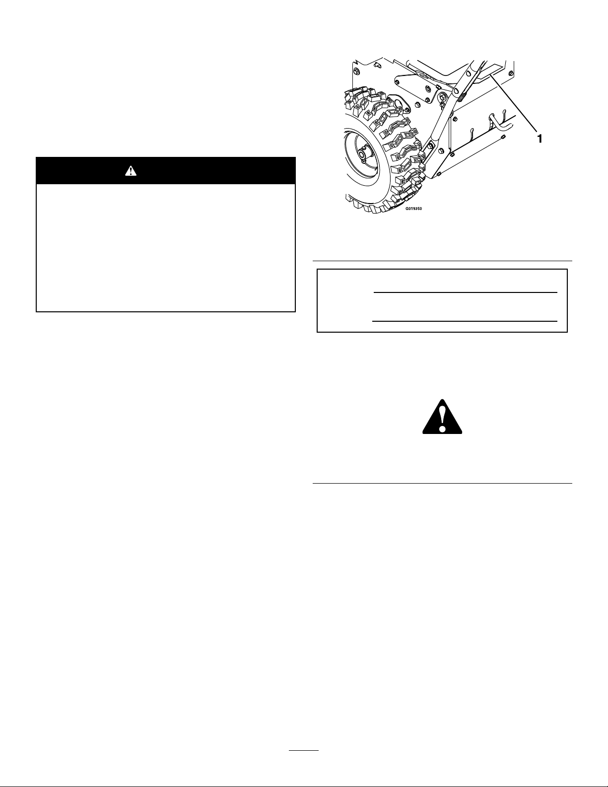
modelandserialnumbersonthemachine.Writethenumbers
inthespaceprovided.
g019350
Figure1
1.Modelandserial-numberlocation
ModelNo.
SerialNo.
Thismanualidentiespotentialhazardsandhassafety
messagesidentiedbythesafetyalertsymbol(Figure2),
whichsignalsahazardthatmaycauseseriousinjuryordeath
ifyoudonotfollowtherecommendedprecautions.
Introduction
Toacquireasparkarresterforyourmachine,seeyourEngine
ServiceDealer.
Thismachineisintendedtobeusedbyresidential
homeownersorprofessional,hiredoperators.Itis
designedforremovingsnow,dust,anddirtfrom
pavedsurfaces,suchasdrivewaysandsidewalks,and
othersurfacesfortrafconresidentialorcommercial
properties,aswellasthatchfromgrass.
Readthisinformationcarefullytolearnhowtooperateand
maintainyourmachineproperlyandtoavoidinjuryand
machinedamage.Youareresponsibleforoperatingthe
machineproperlyandsafely .
YoumaycontactTorodirectlyatwww .Toro.comformachine
andaccessoryinformation,helpndingadealer,ortoregister
yourmachine.
Wheneveryouneedservice,genuineT oroparts,oradditional
information,contactanAuthorizedServiceDealerorToro
CustomerServiceandhavethemodelandserialnumbersof
yourmachineready .Figure1identiesthelocationofthe
g000502
Figure2
1.Safety-alertsymbol
Thismanualuses2wordstohighlightinformation.
Importantcallsattentiontospecialmechanicalinformation
andNoteemphasizesgeneralinformationworthyofspecial
attention.
©2016—TheToro®Company
8111LyndaleAvenueSouth
Bloomington,MN55420
Contactusatwww.Toro.com.
2
PrintedintheUSA
AllRightsReserved

Contents
Safety...........................................................................4
Training.................................................................4
Preparation.............................................................4
Operation...............................................................4
ClearingaCloggedBroom........................................5
MaintenanceandStorage..........................................5
SoundPressure.......................................................5
SoundPower..........................................................5
Hand/ArmVibration..............................................5
SlopeIndicator.......................................................6
SafetyandInstructionalDecals.................................7
ProductOverview..........................................................9
Controls................................................................9
Specications........................................................10
Attachments/Accessories........................................10
Operation....................................................................11
FuelingtheMachine...............................................11
OperatingtheEngine..............................................12
DrivingtheMachine...............................................13
OperatingtheBroom..............................................14
CheckingtheSweepingPath....................................15
AdjustingtheBroomHeight....................................15
AdjustingtheBroomSideAngle...............................16
UsingtheAlternateCasterLocation..........................16
ClearingaCloggedBroom.......................................16
PreventingFreeze-up..............................................17
TransportingtheMachine........................................17
Maintenance.................................................................18
RecommendedMaintenanceSchedule(s)......................18
PreparingforMaintenance.......................................19
Lubrication............................................................19
EngineMaintenance...............................................19
FuelSystemMaintenance........................................22
DriveSystemMaintenance.......................................23
BroomMaintenance...............................................24
MaintainingtheBelts..............................................26
MaintainingtheChassis...........................................28
Storage........................................................................29
PreparingtheMachineforStorage............................29
RemovingtheMachinefromStorage.........................29
Troubleshooting...........................................................30
3

Safety
–Fillthefueltankoutdoorswithextremecare.Never
llthefueltankindoors.
Readandunderstandthecontentsofthismanualbefore
theengineiseverstarted.
Thisisthesafetyalertsymbol.Itisusedtoalertyou
topotentialpersonalinjuryhazards.Obeyallsafety
messagesthatfollowthissymboltoavoidpossibleinjury
ordeath.
Improperlyusingormaintainingthismachinecould
resultininjuryordeath.T oreducethispotential,
complywiththefollowingsafetyinstructions.
Training
•Readtheoperatingandserviceinstructionmanual
carefully.Bethoroughlyfamiliarwiththecontrolsand
theproperuseofthemachine.Knowhowtostopthe
machineanddisengagethecontrolsquickly.
•Donotallowadultstooperatethemachinewithout
properinstruction.
Preparation
CAUTION
Theoperationofanypoweredmachinecanresult
inforeignobjectsbeingthrownintotheeyes.
Alwayswearsafetyglassesoreyeshieldsduring
operationorwhileperforminganadjustmentor
repair.
CAUTION
Thismachineproducessoundlevelsinexcessof85
dBAattheoperator’searandcancausehearingloss
throughextendedperiodsofexposure.
Wearhearingprotectionwhenoperatingthis
machine.
•Keeptheareaofoperationclearofallpersons,particularly
smallchildren,andpets.
•Thoroughlyinspecttheareawhereyouwillusethe
machineandremovealldoormats,sleds,boards,wires,
andotherforeignobjects.
•Donotoperatethemachinewithoutwearingappropriate
personalprotectiveequipmentsuchashearingprotection,
safetyglassesorgoggles,dustmask,andgarments.
Wearfootwear,whichwillimprovetractiononslippery
surfaces.
•Handlefuelwithcare;itishighlyammable.
–Useanapprovedfuelcontainer.
–Neveraddfueltoarunningorhotengine.
–Securethefuelcapafterfuelingandwipeupany
spilledfuel.
•Lettheengineandmachineadjusttooutdoor
temperaturesbeforestartingtoclearsnow.
Operation
•Neverallowchildrentooperatethemachine.
•Donotputhandsorfeetnearorunderrotatingparts.
Keepclearofthedischargeopeningatalltimes.
•Neverdirectdischargeatbystandersorallowanyonein
frontofthemachine.
•Takeallpossibleprecautionswhenleavingthemachine
unattended.Releasethebroom-drivelever,traction-drive
lever,stoptheengine,andremovethekey.
•Alwaysbesureofyourfooting,andkeeparmholdon
thehandles.Walk;neverrun.
•Neveroperatethemachinewithoutgoodvisibilityor
light.
•Donotoperatethemachinewhileill,tired,orunderthe
inuenceofalcoholordrugs.
•Exercisecautiontoavoidslippingorfalling,especially
whenoperatingthemachineinthereversetraveldirection.
•Stoptheenginewheneveryouleavetheoperating
position,beforeuncloggingthebroomhousing,and
whenmakinganyrepairs,adjustments,orinspections.
•Exerciseextremecautionwhenoperatingonorcrossing
graveldrives,walks,orroads.Stayalertforhidden
hazardsortrafc.
•Neveroperatethemachineathightransportspeedson
slipperysurfaces.Usecarewhenreversing.
•Donotclearsnow,dirt,orthatchacrossthefaceof
slopes.Exerciseextremecautionwhenchangingdirection
onslopes.Donotattempttoclearsteepslopes.
•Neveroperatethemachinenearglassenclosures,
automobiles,windowwells,dropoffs,etc.withoutproper
adjustmentofthesnowdischargeangle.Keepchildren
andpetsaway.
•Donotoverloadthemachinecapacitybyattemptingto
clearsnow,dirt,orthatchattoofastofarate.
•Donotruntheengineindoors,exceptwhenstartingit
andformovingthemachineinoroutofthebuilding.
Opentheoutsidedoors;exhaustfumesaredangerous.
•Whencleaning,repairing,orinspecting,ensurethat
therotarybroomandallmovingpartshavestopped.
Disconnectthespark-plugwire,andkeepthewireaway
fromtheplugtopreventaccidentalstarting.
•Disengagethepowertotherotarybroomwhenthe
machineistransportedornotinuse.
4

•Afterstrikingaforeignobject,stoptheengine,remove
thewirefromthesparkplug,thoroughlyinspectthe
machineforanydamage,andrepairthedamagebefore
restartingandoperatingthemachine.
SoundPressure
Thisunithasasoundpressurelevelattheoperator’searof89
dBA,whichincludesanUncertaintyValue(K)of1dBA.
•Ifthemachineshouldstarttovibrateabnormally,stopthe
engineandcheckimmediatelyforthecause.Vibrationis
generallyawarningoftrouble.
•Neveroperatethemachinewithoutproperguards,plates,
orothersafetyprotectivedevicesinplace.
•Useonlyattachmentsandaccessoriesapprovedbythe
manufacturerofthemachine(suchaswheelweights,
counterweights,cabs,etc.).
ClearingaCloggedBroom
WARNING
Therotatingbroomcouldcauseseriousinjury.
Alwaysusecautionwhencleaningthebroom.
Toclearthebroom:
•Parkthemachineonlevelground,stoptheengine,wait
forallmovingpartstostop,andremovethespark-plug
wire(s).
•Sharpobjectscanbecomeentangledinthebristles.Wear
glovesandusecautionwhencleaningoutthebroomof
foreignobjects;neveruseyourbarehands.
Soundpowerlevelwasdeterminedaccordingtothe
proceduresoutlinedinENISO11201.
SoundPower
Thisunithasaguaranteedsoundpowerlevelof101dBA,
whichincludesanUncertaintyValue(K)of1dBA.
Soundpressurelevelwasdeterminedaccordingtothe
proceduresoutlinedinISO11094.
Hand/ArmVibration
Measuredvibrationlevelforlefthand=6.4m/s
Measuredvibrationlevelforrighthand=5.5m/s
UncertaintyValue(K)=2.6m/s
Measuredvaluesweredeterminedaccordingtotheprocedures
outlinedinENISO20643.
2
2
2
MaintenanceandStorage
•Neverattempttomakeanyadjustmentswhiletheengine
isrunning(exceptwherespecicallyrecommendedby
themanufacturer).
•Checkallofthefastenersatfrequentintervalsforproper
tightnesstoensurethatthemachineisinsafe,working
condition.
•Neverstorethemachinewithfuelinthefueltankinside
abuildingwhereignitionsourcesarepresent,suchas
hotwaterandspaceheaters,clothingdryers,etc.Allow
theenginetocoolbeforestoringthemachineinany
enclosure.
•AlwaysrefertotheinstructionsintheOperator’sManual
forimportantdetailsifthemachineistobestoredfor
anextendedperiod.
•Maintainorreplacethesafetyandinstructionlabels,as
necessary.
•Whenoperatinginsnowconditions,runthemachinefor
afewminutesafterthrowingsnowtopreventfreezeup
ofthebroomandhousing.
5
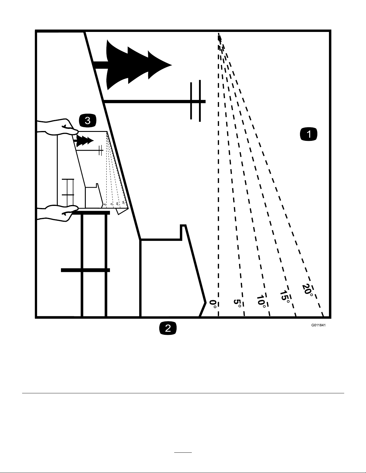
SlopeIndicator
G011841
Figure3
1.Themaximumslopeyoucansafelyoperatethemachineonis10°.Usetheslopeindicatortodeterminethedegreeofslopeof
hillsbeforeoperating.Donotoperatethismachineonaslopegreaterthan10°.Foldalongtheappropriatelinetomatchthe
recommendedslope.
2.Alignthisedgewithaverticalsurface,atree,building,fencepole,etc.
3.Exampleofhowtocompareslopewithfoldededge.
6
g011841
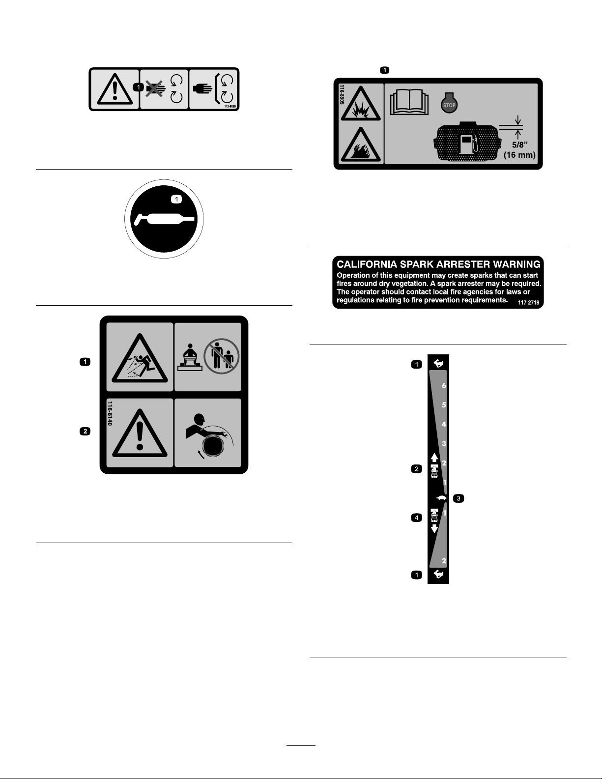
SafetyandInstructionalDecals
Important:Safetyandinstructiondecalsarelocatednearareasofpotentialdanger.Replacedamageddecals.
decal112-9028
112-9028
1.Warning—stayawayfrommovingparts;keepallguardsin
place.
116-8505
1.Explosion/Firehazard—ReadtheOperator'sManual.Stop
theenginebeforellingthefueltank.Leave16mm(5/8
inch)atthetopofthetankforfuelexpansion.Donotoverll
thetank.
decal115-2903
115-2903
1.Grease
117–2718
decal116-8505
decal117-2718
1.Thrownobjecthazard—Do
notoperatewhenpeople
andpetsareinthearea.
decal116-8140
116-8140
2.Warning—Entanglement
hazard—stayclearofthe
rotatingbroom.
decal106-4525
106-4525
OrderPartNo.1 12-6633
1.Fast
2.Forwardspeeds4.Reversespeeds
3.Slow
7
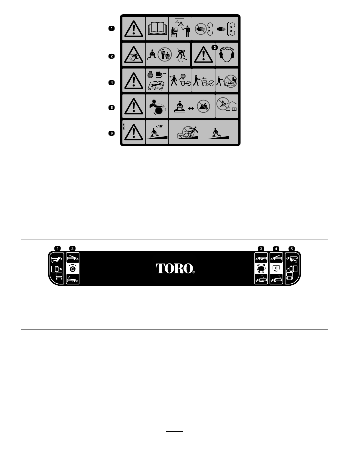
decal116-7370
116-7370
1.Warning—ReadtheOperator’sManual.Donotoperatethis
machineunlessyouaretrained.Stayawayfrommoving
parts;keepallguardsinplace.
4.Warning—Stoptheengineandremovesparkplugbefore
adjusting,servicing,orcleaningmachineandattachments.
Beforeleavingtheoperator’sposition,disengagebroom,
tractiondrive,andstopengine.Lookbehindandtotheside
beforechangingdirections.Donotcarrypassengers.
2.Thrownobjecthazard—Donotoperatewhenpeopleandpets
areinthearea;pickupobjectsthatcouldbethrownbybroom.
5.Warning—Entanglementhazard—stayclearoftherotating
broom.Broombristleswillmeltorburn—keepawayfrom
extremeheatorame.Donotoperateonanyrooforother
elevatedsurface.
3.Warning—Wearhearingprotection.6.Warning—Donotoperateonslopesgreaterthan10degrees.
Useextremecautionwhenoperatingonslopes;operate
acrossslopesnotupanddown.
126–0017
1.Engagetheleft-turnlevertoturnleft.4.EngagethePTOlevertoactivatethePTO.
2.Engagethetraction-controllevertoactivatethetractiondrive.5.Engagetheright-turnlevertoturnright.
3.Engagethebroom-anglelevertoadjustthebroom.
decal126-0017
8
ProductOverview
Figure4
1.Wheel-clutchlever6.Traction-drivelever
2.Handle7.Fuelcap
3.Broom-anglelever8.Broom
4.Broom-drivelever9.Broom-height-adjustment
pin
5.Speed-selectorlever
Controls
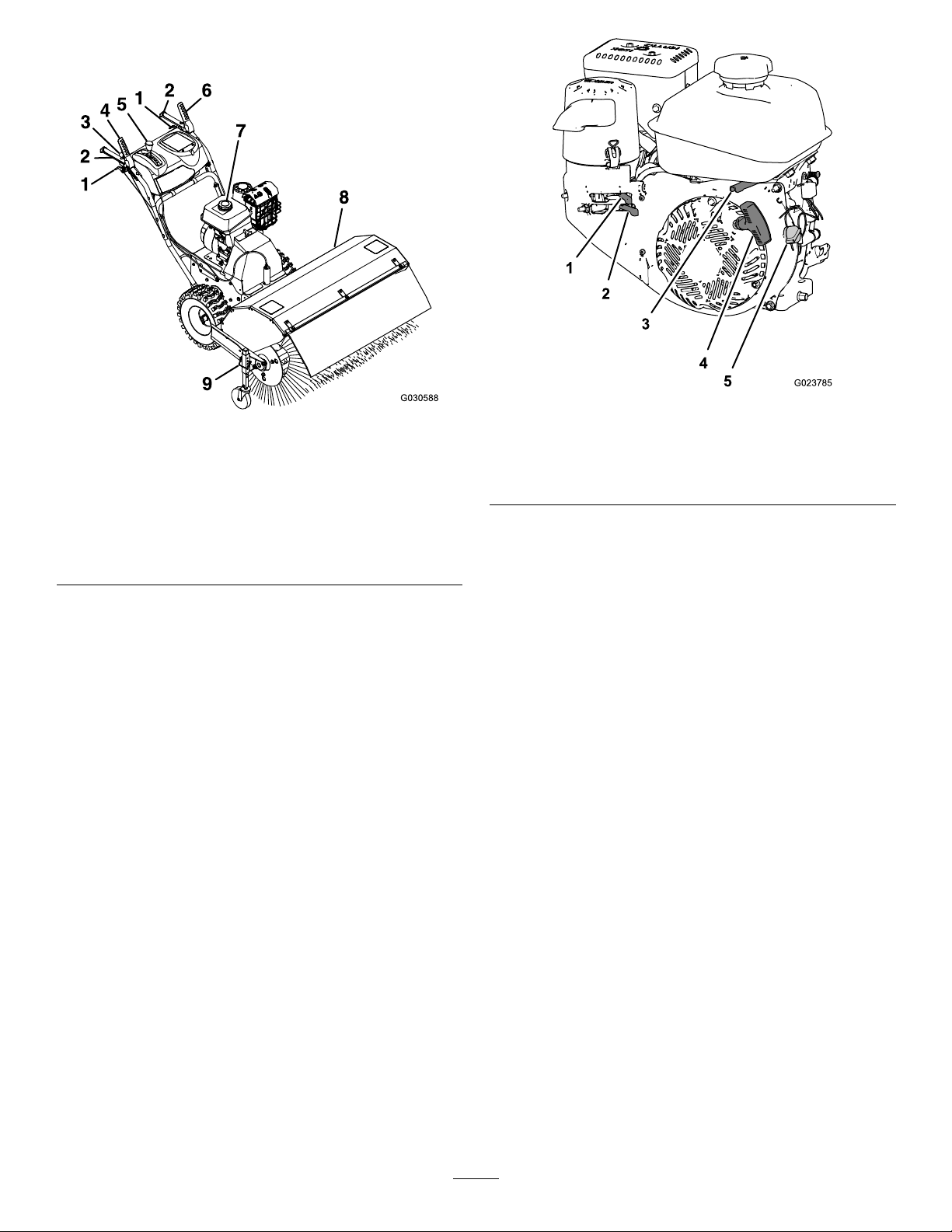
g023785
g030588
1.Chokecontrol
2.Fuel-shutoffvalve5.EngineOn/Offswitch
3.Throttlecontrol
Figure5
4.Engine-recoilhandle
Fuel-ShutoffValve
Usethefuel-shutoffvalvetoshutofftheowoffuelwhen
youwillnotusethemachineforafewdays,parkthemachine
insideabuilding,ortransportthemachinetoandfromthe
jobsite(Figure5).
Determinetheleftandrightsidesofthemachinefromthe
normaloperatingposition.
ChokeControl
Thechokecontrolisthetopleverlocatedontherear,left
sideoftheengineabovethefuel-shutoffvalve(Figure5).
Thechokeisusedtoaidinstartingacoldengine.Movethe
leverlefttotheONpositionforacoldstart.Donotruna
warmenginewiththechokeintheONposition.
Movethelevertothelefttoshutoffthefuel.Movethelever
totherighttoturnonthefuel.
ThrottleControl
Thethrottlecontrolislocatedontherear,rightsideofthe
engineandbelowthefueltank(Figure5).
Thethrottleisusedtocontrolenginespeed.Movingthe
throttlecontroltotheleftincreasestheenginespeed,and
movingitrightdecreasestheenginespeed.
EngineOn/OffSwitch
Locatedontherightsideoftheengine(Figure5).
RotatetheswitchclockwisetotheONpositionbeforestarting
theengine.RotatetheswitchcounterclockwisetotheOFF
positiontostoptheengine.
9
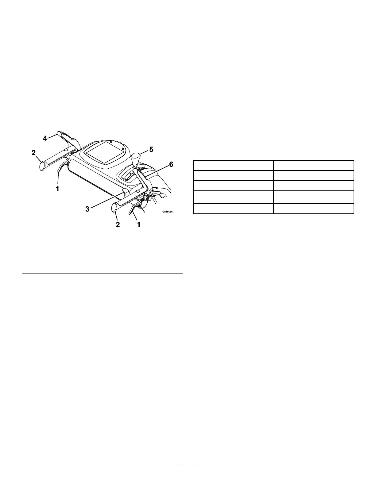
Wheel-ClutchLevers
Speed-SelectorLever
Thewheel-clutchleversarelocatedbelowtherightandleft
handles.
Thewheelclutchleversallowthedrivetomomentarily
disengageto1orbothwheelswiththetraction-drivelever
squeezed.Thisallowsforeasierturningandmaneuvering
themachine(Figure6).
Note:Squeezingbothwheelclutchleverssimultaneously
disengagesthedrivetobothwheels(free-wheeling).This
enablesyoutomanuallymovethemachinebackwardwithout
stoppingtoshiftitintoareversegear.Italsoallowsyouto
maneuverandtransportthemachinemoreeasilywhenthe
engineisnotrunning.
Thespeed-selectionleverislocatedonthemainconsole
panel(Figure6).
Thespeedselectorhas6forwardand2reversesettings.To
changespeeds,releasethetraction-drivelever,andshiftthe
speed-selectorlevertothedesiredsetting.Theleverlocksina
notchateachspeedsetting.
Broom-AngleLever
Thebroom-angleleverislocatedattherighthandle(Figure6).
Thebroom-anglelevercontrolstheanglelock.Thebroom
anglecanbelockedinto3positions:straightahead,orangled
totheleftorright19°.
Specications
Width
Length
Height
Weight
Enginespeed(noload)
118cm(46.5inches)
185.5cm(73inches)
105.5cm(41.5inches)
146.5kg(323lb)
Fullspeed:3600±100rpm
Figure6
1.Wheel-clutchlever4.Traction-drivelever
2.Handle
3.Broom-anglelever6.Broom-drivelever
5.Speed-selectorlever
Broom-DriveLever
Thebroom-driveleverislocatedabovetherighthandle
(Figure6).
Toengagethebroom,squeezethelevertothehandle.To
disengagethebroom,releasetherightlever.
Traction-DriveLever
Thetraction-driveleverislocatedabovethelefthandle
(Figure6).
Thetraction-drivelevercontrolstheforwardandreverse
motionofthemachine.Toengagethetractiondrive,squeeze
thelevertothehandle.
g018688
Attachments/Accessories
AselectionofToroapprovedattachmentsandaccessoriesis
availableforusewiththemachinetoenhanceandexpand
itscapabilities.ContactyourAuthorizedServiceDealeror
Distributororgotowww .Toro.comforalistofallapproved
attachmentsandaccessories.
Note:Holdingdownthetraction-driveleveragainstthe
handleengagesthetractiondrivetobothwheels.
10
Operation
FuelingtheMachine
Fueltankcapacity:4.1L(1.0USgallon)
•Forbestresults,useonlyclean,fresh(lessthan30days
old),unleadedgasolinewithanoctaneratingof87or
higher((R+M)/2ratingmethod).
•Ethanol:Gasolinewithupto10%ethanol(gasohol)
or15%MTBE(methyltertiarybutylether)byvolume
isacceptable.EthanolandMTBEarenotthesame.
Gasolinewith15%ethanol(E15)byvolumeisnot
approvedforuse.Neverusegasolinethatcontains
morethan10%ethanolbyvolume,suchasE15
(contains15%ethanol),E20(contains20%ethanol),or
E85(containsupto85%ethanol).Usingunapproved
gasolinemaycauseperformanceproblemsand/orengine
damagewhichmaynotbecoveredunderwarranty.
•Donotusegasolinecontainingmethanol.
•Donotstorefueleitherinthefueltankorfuelcontainers
overthewinterunlessafuelstabilizerisused.
•Donotaddoiltogasoline.
Important:Donotusefueladditivesotherthanafuel
stabilizer/conditioner.Donotusefuelstabilizerswithan
alcoholbasesuchasethanol,methanol,orisopropanol.
DANGER
Whenfueling,undercertaincircumstances,astatic
chargecandevelop,ignitingthegasoline.Areor
explosionfromgasolinecanburnyouandothers
anddamageproperty.
•Alwaysplacegasolinecontainersontheground
andawayfromyourvehiclebeforelling.
•Donotllgasolinecontainersinsideavehicleor
onatruckortrailerbedbecauseinteriorcarpets
orplastictruckbedlinersmayinsulatethe
containerandslowthelossofanystaticcharge.
•Whenpractical,removegasoline-powered
equipmentfromthetruckortrailerandrefuel
theequipmentwithitswheelsontheround.
•Ifthisisnotpossible,thenrefuelsuch
equipmentonatruckortrailerfromaportable
container,notfromagasolinedispensernozzle.
•Ifyoumustuseagasolinedispensernozzle,
keepthenozzleincontactwiththerimofthe
fueltankorcontaineropeningatalltimesuntil
fuelingiscomplete.
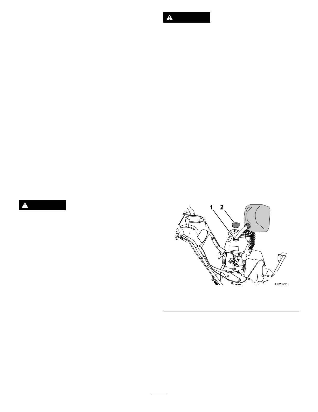
AddingFueltotheFuelTank
1.Cleanaroundthefuel-tankcap(Figure7).
DANGER
Incertainconditions,gasolineisextremely
ammableandhighlyexplosive.Areorexplosion
fromgasolinecanburnyouandothersandcan
damageproperty.
•Fillthefueltankoutdoors,inanopenarea,and
whentheengineiscold.Wipeupanygasoline
thatspills.
•Donotllthefueltankcompletelyfull.Add
gasolinetothefueltankuntilthelevelis6to13
mm(1/4to1/2inch)belowthebottomofthe
llerneck.Thisemptyspaceinthetankallows
thegasolinetoexpand.
•Neversmokewhenhandlinggasoline,andstay
awayfromanopenameorwhereasparkmay
ignitethegasolinefumes.
•Storegasolineinanapprovedfuelcontainerand
keepitoutofthereachofchildren.
•Neverbuymorethana30-daysupplyof
gasoline.
g023791
Figure7
1.Fillerneck2.Fuel-tankcap
2.Removethecapfromthefueltank(Figure7).
3.Fillthefueltankwithunleadedgasolinetowithin6to
13mm(1/4to1/2inch)fromthetopofthetank.Do
notllintothellerneck.
Important:Donotllthetankmorethan6mm
(1/4inch)fromthetopofthetankbecausethe
gasolinemusthaveroomtoexpand.
4.Installthefuel-tankcapandwipeupanyspilled
gasoline(Figure7).
11

OperatingtheEngine
PositioningtheAir-CleanerCoverfor
ColdorWarmAirTemperature
Important:Runningtheenginewiththeair-cleaner
coverpositionedforcold-weatheroperationinnormal
conditionscandamagetheengine.
Theair-cleanercoverhas2positions:thecoldornormal,
ambientairpositions:
Adjusttheair-cleanercoverasfollows:
•Whenoperatinginacoldambientaircondition(cold
airtemperatureandhumidity)—positiontheair-cleaner
coverwithsnowakedecalfacingout(Figure8).
Note:Usethispositionifyourmachineexhibits
carburetoricing.Symptomsincludetheengineruns
roughatidleorlowspeed,anditdischargesblackor
whitesmokeintheexhaust.
•Whenoperatinginanormalambientair
condition—positiontheair-cleanercoverwithsundecal
facingout(Figure8).
Note:Usethispositionifyourmachineisnotexhibiting
carburetoricing.
OpeningtheFuel-ShutoffValve
Movethefuel-shutoffvalvelocatedbelowthechoke,tothe
righttoturnonfuel(Figure9).
g023826
Figure9
1.FUELONposition3.Choke
2.Fuel-shutoffvalve
StartingtheEngine
1.Ontherightsideoftheengine,rotatetheengine
On/OffswitchclockwisetotheONposition(Figure
10).
1.Normalambientair
position
Figure8
2.Coldambientairposition
g023827
g023829
Figure10
1.Engine-recoilhandle
2.Throttle
3.Engineswitch(OFF
position)
4.Engineswitch(ON
position)
2.Ontherear,leftsideoftheengine,movethechoke
levertothelefttotheONposition.Onawarmengine,
leavethechokeintheOFFposition(Figure9).
12

3.PlacethethrottlemidwaybetweentheSLOWandFAST
positionslocatedonrear,rightsideoftheengine
(Figure10).
4.Slowlypulltheengine-recoilhandleuntilyoufeel
resistanceandthenstop(Figure10).
Note:Allowtherecoilhandletoreturnandthen
sharplypullitstraightout.
Note:Allowtheropetoreturnslowly.
5.Allowtheenginetowarmupforseveralminutes,then
movethechoketowardtheOFFposition(Figure9).
StoppingtheEngine
1.Releasethebroom-driveleverandthetraction-drive
lever.
2.PlacethethrottlemidwaybetweentheSLOWandFAST
positions(Figure10).
3.Allowtheenginetorunforaminimumof15seconds,
thenturntheengineOn/OffswitchtotheOFF
positiontostoptheengine(Figure10).
4.Waitforallmovingpartstostopbeforeleavingthe
operatingposition.
g001012
Figure11
Note:Ifthegroundspeedistoofast,debrisorsnow
willpileupinfrontofthebroomcausingthebroom
tobulldozeinsteadofsweep.Thiscandamagethe
bristlesandthedriveline.
2.Slowlysqueezethelefttraction-drivelevertothe
handle(Figure12).
Note:Holdingdownthetraction-driveleveragainst
thehandleengagesthetractiondrivetobothwheels.
5.Usethefuel-shutoffvalvetoshutofftheowoffuel
whenyouwillnotusethemachineforafewdays,park
themachineinsideabuilding,ortransportthemachine
toandfromthejobsite(Figure9).
DrivingtheMachine
CAUTION
Ifthetractiondriveisnotproperlyadjusted,the
machinemaymoveinthedirectionoppositeof
whatyouintended,causinginjuryand/orproperty
damage.
Carefullycheckthetractiondriveandadjustit
properly,ifnecessary.
Important:Ifthemachinemoveswhenthetraction
leverisinthereleasedposition,checkthetractioncable;
refertoCheckingtheTractionCable(page23)and
AdjustingtheTractionCable(page23)orcontactyour
authorizedT orodealer.
g017789
Figure12
3.Tostopthetractiondrive,releasethetraction-drive
lever.
4.Tomoveforward,engagethetractiondriveandslowly
squeezethelefthandtractionlevertothehandle
(Figure13).
Note:Momentarilysqueezingandreleasingtheleftor
rightwheel-clutchleverallowsforsteeringadjustments
tokeepthemachinegoinginastraightline,especially
indeepsnow.
Note:Toturnright,liftupontherightwheel-clutch
leverandsqueezeittowardthehandle.Thisdisengages
thedrivetotherightwheel,whiletheleftwheel
continuesdriving,andthemachineturnstotheright.
DrivingForward
1.Placethespeedselectorlevertothedesiredforward
position,makingsurethatitlocksinthenotch(Figure
11).
13

OperatingtheBroom
DANGER
Whenthemachineisinoperation,contactwith
rotatingormovingpartswillseverelyinjurehands
andfeet.
Figure13
Note:Similarly,squeezingtheleftwheel-clutchlever
turnsthemachinetotheleft.
Note:Whenyoucompletetheturn,releasethe
wheel-clutchlever.Thedriveengagesbothwheels
(Figure14).
Figure14
5.Tostopthetractiondrive,releasethetraction-drive
lever.
DrivingtheMachineRearward
g001307
•Beforeadjusting,cleaning,inspecting,
troubleshooting,orrepairingthemachine,stop
theengineandwaitforallmovingpartstostop.
Disconnectthewirefromthesparkplugand
keepitawayfromtheplugtopreventsomeone
fromaccidentallystartingtheengine.
•Staybehindthehandlesandawayfromthe
broomwhileoperatingthemachine.
•Keepface,hands,feet,andanyotherpartof
yourbodyorclothingawayfromconcealed,
moving,orrotatingparts.
WARNING
Contactwitharotatingbroomcanresultin
g001308
seriouspersonalinjuryordeathtotheoperatoror
bystanders.
•Toremoveanobstructionfromthebroom;refer
toClearingaCloggedBroom(page16).
•Donotoperatethemachineifthebroomdrive
leverisnotfunctioningproperly.Contactyour
authorizedT orodealer.
1.Placethespeed-selectorleverintothedesired
reverse-speedrange,makingsurethatthespeed
selectorlocksinthenotch.
2.Tomoverearward,engagethetractiondriveandslowly
squeezethelefttractionlevertothehandle.
Note:Momentarilysqueezingandreleasingtheleftor
rightwheel-clutchleverallowsforsteeringadjustments
tokeepthemachinegoinginastraightline.
Note:Toturnright,squeezetherightwheel-clutch
levertowardthehandle.Thisdisengagesthedriveto
therightwheelwhiletheleftwheelcontinuesdriving,
andthemachineturnstotheright.
Note:Similarly,squeezingtheleftwheel-clutchlever
turnsthemachinetotheleft.
Note:Squeezingbothwheel-clutchleverssimultaneously
disengagesthedrivetobothwheels.Thisenablesyouto
movethemachinerearwardwithoutstoppingtoshiftitintoa
reversegear.Italsoallowsyoutomaneuverandtransportthe
machinemoreeasilywhentheengineisnotrunning.
WARNING
Therotatingbroomcanthrowstonesandother
foreignobjects,causingseriouspersonalinjuryto
theoperatorortobystanders.
•Keeptheworkingareaclearandfreeofall
objectsthatthebroomcouldpickupandthrow.
•Keepallchildrenandpetsawayfromthearea
ofoperation.
CAUTION
Whenthebroomisengaged,itmaydrivethe
machineinthereversedirection.Ifthebroom
heightisadjustedtoolow,themachinemaymove
moreforcefullyinthereversedirection,causing
injuryand/orpropertydamage.
Carefullycheckthebroomheightandadjustit
properlyorcontactyourauthorizedT orodealer.
1.SettheenginethrottletotheFastposition.
14

2.Placethespeedselectorleverintothedesiredposition
andslowlysqueezethelefthandtractiondrivelever.
Important:Makesurethatthetractiondriveis
engagedbeforeoperatingthebroom;otherwise,
thebroommaydrivethemachineinthereverse
direction.
3.Toengagethebroom,slowlysqueezetherightbroom
levertothehandle(Figure15).
g017922
Figure16
Figure15
•Iftheengineslowsdownunderaloadorthe
wheelsslip,shiftthemachineintoalowergear.
•Ifthefrontofthemachineridesup,shiftthe
machineintoalowergear.Ifthefrontcontinues
torideup,liftuponthehandles.
4.Tostopthebroom,releasetherightlever.
CheckingtheSweepingPath
Abroomsweepswiththetipsofitsbristles.Whenyouapply
toomuchdownwardpressure,thebroomnolongerusesits
tips;thebroomisnowworkingwiththesidesofthebristles.
Thislimitstheickingactionofthebristlesandsweeping
effectiveness,decreasingtheservicelifeofthebroom.
1.Drivetoaat,dustyareaandstopthemachine.
2.Withtheenginerunningmovethethrottlemidway
betweenSLOWANDFAST.
g001013
1.51to102mm(2to4
inches)maximumwidth
2.Lengthofbroom
3.Sweptarea
8.Adjustthebroomheight,ifnecessary.
AdjustingtheBroomHeight
1.Drivetoaat,dustyareaandstopthemachine.
2.Disengagethebroomandstoptheengine.
3.Waitforallmovingpartstostopbeforeleavingthe
operatingposition.
4.TurntheengineOn/OffswitchtotheOFFposition.
5.Toadjustthebroomheight,removeandretainthepin
fromtheadjustersleeveandwheeltubeofthecaster
(Figure17).
3.Engagethebroomandallowthebroomtosweepfor
approximately30seconds.
4.Disengagethebroomandstoptheengine.
5.Waitforallmovingpartstostopbeforeleavingthe
operatingposition.
6.TurntheengineOn/OffswitchtotheOFFposition.
7.Makesuretheareasweptequalsthelengthofthe
broomandamaximumwidthof51to102mm(2to
4inches).
1.Caster-wheeltube
2.Positionstoachieve3mm
(1/8inch)increments
15
g030413
Figure17
3.Pin
4.Adjustersleeve

6.Raiseorlowerthecasterwheeltubetoachievethe
sweepareaasstatedinCheckingtheSweepingPath
(page15).
UsingtheAlternateCaster Location
Note:Selectanyholecombinationthatisinalignment
toplaceandlatchtheretainingpin;matchthesame
positionontheotherside.
7.Fornetuningadjustments,slidetheadjustersleeve
1pinholeupordownonthecasterwheeltubeto
adjustthebroomheightin3mm(1/8inch)increments
(Figure17).Repeatsteps5through7fortheother
casterwheel.
•Toraisethebroomin3mm(1/8inch)increments,
slightlyraisetheadjustersleeveandinsertthepin
intothenextpinholebelowthecurrentholeused.
•Tolowerthebroomin3mm(1/8inch)increments,
slightlylowertheadjustersleeveandinsertthepin
intothenextpinholeabovethecurrentholeused.
8.Whenyouattainthedesiredheight,securethepinon
eachcasterwheel,andcheckthesweepingarea.
AdjustingtheBroomSide Angle
1.Disengagethebroomandstoptheengine.
Whenworkinginsnow ,mountthecastersbehindthebroom
bristles(Figure18).
Figure18
1.Hardware
2.Caster
ClearingaCloggedBroom
g030284
2.Waitforallmovingpartstostop.
3.Pushtheleverdownwiththethumbofyourrighthand
(Figure6).
4.Squeezetheleftwheel-clutchlevertothehandleand
pushthebroomhousingtothedesiredangle.
Note:Thebroomcanrotate19°totherightorleft,
orstraightahead.
5.Oncethebroomispositioned,releasethebroomangle
lever.
6.Releasetheleftwheel-clutchleverandmakesurethat
thebroomislockedintoplace.
WARNING
Therotatingbroomcouldcauseseriousinjury.
Shutoffthemachineandallowallrotatingpartsto
stopbeforecleaningthebroom.
•Ifthebroombecomesclogged,stayintheoperating
positionandreleasethelefttraction-drivelever.While
engagingthebroom,pushdownonthehandlestoraise
thefrontofthemachineafewcentimeters(inches)offthe
pavement.Thenliftthehandlesquicklytobumpthefront
ofthemachineonthepavement.Repeatifnecessary.
•Ifyoucannotunclogthebroombybumpingthefront
ofthemachine:
–Parkthemachineonlevelground.Stoptheengine,
waitforallmovingpartstostop,anddisconnectthe
spark-plugwire.
–Sharpobjectscanbecomeentangledinbristles.Use
glovesandcautionwhenremovingforeignobjects
fromthebroom;donotuseyourhands.
16

PreventingFreeze-up
•Insnowyandcoldconditions,somecontrolsandmoving
partsmayfreeze.Donotuseexcessiveforcewhen
tryingtooperatefrozencontrols.Ifyouhavedifculty
operatinganycontrolorpart,starttheengineandletit
runforafewminutes.
•Afterusingthemachine,lettheenginerunforafew
minutestopreventmovingpartsfromfreezing.Engage
thebroomtoclearanyremainingsnowfrominsidethe
housing.Stoptheengineandwaitforallmovingpartsto
stop,anddisconnectthespark-plugwire.Removeallice,
snow,orotherdebrisfromthemachine.
•Connectthespark-plugwire.Withtheengineswitchin
theOFFposition,pulltherecoil-starterhandleseveral
timestopreventtherecoilstarterfromfreezingup.
TransportingtheMachine
WARNING
Usingrampsthatarenotstrongenoughorproperly
supportedtoloadthemachineontothetransport
vehiclecouldbedangerous.Therampscould
collapse,causingthemachinetofall,whichcould
causeinjury.
•Useproperrampsthataresecuredtothetruck
ortrailer.
•Keepfeetandlegsoutfromunderthemachine
whenloadingandunloading.
PreparingtoTransporttheMachine
Performthefollowingbeforetransportingthemachine:
•Besurethatthefuel-shutoffvalveisclosed.
•Useaheavy-dutytrailertotransportthemachine.Place
themachineineitheraforwardorreversegear,then
blockthewheels.
•Securelyfastenthemachinetothetrailerwithstraps,
chains,cables,orropes.
•Besurethatthetrailerhasallthenecessarylightingand
markingasrequiredbylaw.
17

Maintenance
Note:Determinetheleftandrightsidesofthemachinefromthenormaloperatingposition.
RecommendedMaintenanceSchedule(s)
MaintenanceService
Interval
Aftertherst2hours
Aftertherst5hours
Beforeeachuseordaily
Every50hours
Every100hours
Every200hours
Every300hours
Yearly
Yearlyorbeforestorage
MaintenanceProcedure
•Checkthetractioncable.
•Checkthebroomcable.
•Changetheengineoil.
•Checktheengineoillevel.
•Checkthebroom-shaftshearpin.
•Checkforloosehardware.
•Cleanthefoampre-cleaner(morefrequentlyindustyconditions).
•Checkthetirepressure.
•Checktheconditionofthebelts.
•Lubricatethebroom-angle-lockpin.
•Changetheengineoil(morefrequentlyinsevereconditions).
•Checkthesparkplug.
•Replacethefoampre-cleaner.
•Replacethepaperairlter(morefrequentlyindustyconditions).
•Lubricatethehexshaft.
•Checkthetractioncable.
•Checkthebroomcable.
•Checktheairpressureinthedrivetiresandinatethemto116to137kPa(17
to20psi).
•Drainthegasolineandruntheenginetodryoutthefueltankandthecarburetorat
theendoftheseason.
•Haveanauthorizedservicedealerinspectandreplacethetraction-drivebelt,if
necessary.
Important:Youcanndmoreinformationaboutmaintainingandservicingyourmachineatwww.Toro.com.
Important:Refertoyourengineoperator'smanualforadditionalmaintenanceprocedures.Forengineadjustments,
repairs,orwarrantyservicenotcoveredinthismanual,contacttheauthorizedengineservicedealer.
18

PreparingforMaintenance
1.Movethemachinetoalevelsurface.
2.Shutofftheengineandallowittocool.
3.Disconnectthespark-plugwirefromthesparkplug
andkeepthewireawayfromtheplug,toprevent
accidentalstarting(Figure19).
2.Removethebeltcoverandtheengineshield.
3.Movethespeed-selectorlevertotheR2position.
4.Dipalong,clean,small-tippedpaintbrushin
automotiveengineoilandlightlylubricatethehexshaft
(Figure21).
Important:Donotgetoilontherubberwheelor
thealuminumfriction-driveplateasthetraction
drivewillslip(Figure21).
Note:Rockthemachineforwardandrearwardto
rotatethehexshaft.
Figure19
1.Spark-plugwire
Lubrication
LubricatingtheBroom-Angle-LockPin
andtheHexShaft
ServiceInterval:Every100hours
Yearly
1.Lubricatethebroom-angle-lockpinttingwithNo.2
lithiumgrease(Figure20).
g023810
Figure21
1.Aluminumfriction-drive
plate
2.Hexshaft
g019054
5.Movethespeedselectorlevertoposition6.
6.Lubricatetheotherendofthehexshaft.
7.Movethespeedselectorleverforwardandrearward
afewtimes.
8.Installthebeltcoverandtheengineshield.
EngineMaintenance
ServicingtheAirCleaner
ServiceInterval:Every50hours—Cleanthefoam
pre-cleaner(morefrequentlyindusty
conditions).
Every200hours—Replacethefoampre-cleaner.
Every300hours—Replacethepaperairlter(more
frequentlyindustyconditions).
1.Broom-angle-lockpin
Figure20
Important:Donotoperatetheenginewithouttheair
lterassembly;extremeenginedamagemayoccur.
1.Releasethelatchesonthecoverfortheaircleaner.
2.Removethecoverandcleanitthoroughly(Figure22).
g030414
Note:Becarefultopreventdirtanddebrisfrom
fallingintothebase.
19

Figure22
G023796
1.Air-lterbase4.Cover
2.Paperairlter
3.Foampre-cleaner
5.Latchontheair-cleaner
cover(2)
3.Removethefoampre-cleaner,washitwithamild
detergentandwater,andthenblotitdry(Figure22).
4.Removeandinspectthepaperairlter(Figure22);
discarditifitisexcessivelydirty.
Important:Donottrytocleanapaperlter.
5.Wipedirtawayfromthebaseandthecoverwitha
moistrag.
Note:Becarefultopreventdirtanddebrisfrom
enteringtheairductleadingtothecarburetor.
6.Installthefoampre-cleanerontothepaperairlter
(Figure22).
g023809
Figure23
1.Alignment-arrowdecal(normalambientairpositionshown)
9.Securetheair-ltercovertothebasewiththelatches.
g023795
CheckingtheEngine-OilLevel
ServiceInterval:Beforeeachuseordaily
EngineOilType:Toro4–CyclePremiumEngineOil
Usehigh-qualitydetergentoils(includingsynthetic)ofAPI
(AmericanPetroleumInstitute)serviceclassSJorhigher.
Selecttheviscositybasedontheairtemperatureattimeof
operationasshowninthetablebelow .
g023796
Figure24
Note:Useanewpaperairlterifyoudiscardedthe
oldone.
7.Installtheairlterassemblytotheair-lterbase
(Figure22).
8.Alignthearrowdecalontheair-cleanercoverandthe
arrowdecalonthebase(Figure23).
Checktheoillevelwhentheengineiscold.
1.Cleantheareaaroundthedipstick.
2.Removethedipstickandreadtheoillevel(Figure25).
20

Figure25
ChangingtheEngineOil
ServiceInterval:Aftertherst5hours
Every100hours(morefrequentlyinsevere
conditions).
Oilcapacity:0.60L(0.63qt)
Note:Draintheengineoilwhiletheengineiswarm.
1.Placeapanunderdrainttingandremovetheoil-drain
cap(Figure26).
g023794
1.Fillerneck2.Dipstick
3.Removethedipstickandwipeofftheoilwithaclean
rag.
4.Insertthedipstickintothellerneck,restitontheoil
llerneck,andturnitcounterclockwiseuntilthecap
dropsdowntolowestpointofthethreadleads.
Note:Donotthreadthecapontothetube.
5.Removedipstickandcheckoillevel.
Note:Donotoperatetheenginewiththeoillevel
belowtheAddmarkorabovetheFullmarkonthe
dipstick.
Note:Theoillevelshouldbeattopoftheindicator
onthedipstick(Figure25).
•Iftheoillevelislow ,performthefollowing:
A.Pourthespeciedoilintothellerneck
(Figure25).
Note:Donotoverlltheenginewithoil.
B.Repeatsteps3through5.
•Iftheoillevelishigh,preformthefollowing:
A.Removethecapfromthedraintting.
B.Draintheoiluntiltheoillevelisatthetopof
theindicatorondipstick;refertosteps1of
ChangingtheEngineOil(page21).
C.Installthecapontothedraintting;referto
step2ofChangingtheEngineOil(page21).
6.Insertthedipstickintothellerneckandtightenthe
dipstickbyhand.
Figure26
1.Draintting
2.Cap
3.Drainpan
2.Allowtheoiltodrainandtheninstalltheoil-draincap.
3.Cleanaroundthellerneckandremovethedipstick.
4.Filltothespeciedcapacitywiththespeciedoiland
replacethedipstick;refertoCheckingtheEngine-Oil
Level(page20).
Note:Donotoverlltheenginewithoil.
5.Wipeupanyspilledoil.
6.Starttheengineandcheckforleaks.
7.Stoptheengineandchecktheoillevel;referto
CheckingtheEngine-OilLevel(page20).
g023792
21

CheckingtheSparkPlug
G019300
1 2
4
3
ServiceInterval:Every100hours
Sparkplugtype:Champion®RC12YC,Kohler®12132
02-S,orKoher2513214-S(RFIcompliant)
Spark-pluggap:0.76mm(0.030inch)
1.Disconnectthespark-plugwirefromtheterminalof
thesparkplug(Figure19).
2.Cleantheareaaroundthebaseofthesparkplug.
3.Removethesparkplugfromthecylinderheadby
rotatingtheplugcounterclockwise.
4.Examinetheplugforwearanddamage(Figure27).
Important:Replaceacracked,fouled,ordirty
sparkplug.Donotcleantheelectrodes,because
gritenteringthecylindercandamagetheengine.
FuelSystemMaintenance
DrainingtheFuelSystem
1.Locatethedrainboltthatisinthesideportofthe
carburetorbowl(Figure28).
Figure27
1.Groundelectrode
2.Centerelectrode4.Spark-pluggap0.76mm
3.Insulator
(0.030inch)
5.Checkthespark-pluggapwithawiregauge(Figure27).
Note:Ifnecessary,adjustthegapto0.76mm(0.030
inch)bycarefullybendingthegroundelectrode.
6.Installthesparkplugbythreadingitintothecylinder
headandtorquingtheplugto20N-m(14lb-ft).
7.Connectthespark-plugwiretotheterminalofthe
sparkplug.
g023828
Figure28
g019300
1.Bowl-retainingscrew2.Drainbolt
2.Aligntheequipmentthatyouwillusetocollectthefuel
beneaththedrainscrew .
3.Removethedrainscrewfromthecarburetorandallow
thefueltodrainfromthefueltankandthecarburetor.
Note:Donotremovethebowl-retainingscrewfrom
carburetor.
22

Figure30
3
g019016
g001568
Figure29
1.Sideportofthecarburetor
bowl
2.Drainbolt
4.Installthedrainboltintothesideportofthecarburetor.
DriveSystemMaintenance
CheckingtheTirePressure
ServiceInterval:Every50hours
1.Turnofftheengine,waitforallmovingpartstostop,
andleaveengineswitchintheOFFposition.
2.Checkthetirepressureinthedrivetires.
1.Pin
2.6mm(1/4inch)
AdjustingtheTractionCable
g023831
Ifthemachinedoesnotdriveintheforwardorreversespeeds
oritdriveswhenyoureleasethetractionlever,adjustthe
tractioncable.
Withthetractionleverdisengaged,checkthepininthe
elongatedslotintheleftsideofthemachineabovethetire.
Thereshouldbeagapof6mm(1/4inch)fromthefront
oftheslottothefrontedgeofthepin;refertoChecking
theTractionCable(page23).
Ifthelefttractioncableisnotproperlyadjusted,dothe
followingsteps:
1.Loosenthejamnut(Figure31).
2.Loosenortightentheturnbuckletoadjustthepinuntil
itisthepropergapfromthefrontedgeoftheslot
(Figure31).
3.Tightenthejamnut(Figure31).
3.Inatethedrivetiresto117to138kPa(17to20psi).
CheckingtheTractionCable
ServiceInterval:Aftertherst2hours
Yearly
1.Turnofftheengine,waitforallmovingpartstostop,
anddisconnectthespark-plugwire.
2.Withthetractionleverdisengaged,checkthepinin
theelongatedslotintheleftsideofthemachineabove
thetire(Figure30).
Note:Thereshouldbeagapof6mm(1/4inch)
fromthefrontoftheslottothefrontedgeofthepin
(Figure30).
Note:Ifadjustmentisnecessary,refertoAdjusting
theTractionCable(page23).
g019016
Figure31
1.Jamnut2.Turnbuckle
AdjustingtheWheel-ClutchCable
1.Squeezetheleverfully,thencheckthegapbetweenthe
bottomofthehandleandthewheel-clutchleverend
(Figure32).
23

Figure32
Note:Thegapshouldbeapproximatelythethickness
ofapencil(6mmor1/4inch).Ifitisgreater,loosen
thecableclampnut,slidethecablejacketupslightly,
tightenthecableclampnut,andcheckthegapagain.
2.Repeatfortheothercable(Figure32).
BroomMaintenance
g001306
CheckingtheBroom-ShaftShearPin
ServiceInterval:Beforeeachuseordaily
1.Movethemachinetoalevelsurface.
2.Turnofftheengine,waitforallmovingpartstostop,
anddisconnectthespark-plugwire.
3.Checktheshearpinlocatedonthebroomshafton
eithersideofthegearbox.
Figure33
1.Nut
2.Shearpin
g023811
Figure34
1.Broomsupport4.Endbearing
2.Locknut
3.Washer
5.Carriagebolt
3.Manuallypullthepowerunitrearwardtoremovethe
broomassemblyfromthemachine.
4.Supportthesplineshaftoneithersideofthegearbox.
5.Standthebroomcoreassemblyonendsothattheend
retainerplatefacesupward(Figure35).
g019073
4.Iftheshearpinisdamaged,removethepin,replaceit,
andsecuretheitwithanut.
ReplacingWornorDamagedBroom
Segments
ServiceInterval:Asrequired.
1.Raisethebroombysettingthecasterpositions.
2.Onbothsidesofthemachine,removeandretainthe
carriagebolts,washers,andlocknutsthatsecurethe
endbearingstothebroomsupport.
1.Hardware
2.End-retainerplate
3.Broomsegment
6.Removeandretainthehardwarefromtheend-retainer
plate(Figure35).
24
g018760
Figure35
4.Supportshaft
5.Alignmentngers

7.Removethedamagedbroomsegment(s).
AdjustingtheBroomDrive
8.Installthenewsegment(s)bystaggeringthemetalring
alignmentngersasshowninFigure35.
Important:Y oumaydamagethebroomassembly
ifyoudonotproperlyinstallthebroomsegments.
9.Installthebroomassemblyontothemachine.
Important:Makesurethatthebearingsetscrews
aretightenedbeforeoperatingthebroom.
CheckingtheBroomCable
ServiceInterval:Aftertherst2hours
Yearly
1.Turnofftheengine,waitforallmovingpartstostop,
anddisconnectthespark-plugwire.
2.Removethebeltcoverandengineshield.
3.Withthebroomleverdisengaged,ensurethegap
betweenthebroom-clutchassemblyandthetabis3.2
mm(1/8inch).
Note:Ifthebroomisnotproperlyadjusted,referto
AdjustingtheBroomDrive(page25).
Ifthebroomcableisnotproperlyadjusted;refertoChecking
theBroomCable(page25),andthenperformthefollowing
steps:
1.Loosenthejamnut(Figure37).
g001024
Figure37
1.Jamnut2.Turnbuckle
1.Broom-clutchassembly
2.Tab
2.Loosenortightentheturnbucklethatadjuststhe
tensiononthecable(Figure37).
3.Adjusttheturnbuckleuntilthegapbetweenthebroom
clutchassemblyandthetabis3.2mm(1/8inch)
(Figure36).
4.Tightenthejamnut.
5.Ifthebroomcableisproperlyadjustedbutaproblem
remains,contactyourAuthorizedToroServiceDealer.
g019072
Figure36
3.3.2mm(1/8inch)
25

MaintainingtheBelts
CheckingtheConditionoftheBelts
ServiceInterval:Every50hours
1.Removetheknobandwasherthatsecurestheengine
coverandthebeltcovertothemachine(Figure38).
g023815
Figure39
Figure38
1.Knob4.Platenut
2.Washer5.Beltcover
3.Enginecover
2.Checkthe2beltsfordamageorwear.
Note:Replaceanydamagedorexcessivelyworn
belt(s).
3.Alignthebeltcoverandtheenginecovertothe
machineandtheplatenut(Figure38).
4.Securethebeltcoverandtheenginecovertothe
machinewiththeknobandwasher(Figure38).
1.Spacer
2.Pulleyshield5.Bolt
3.Beltguide
4.Washer
3.Slipthebeltforwardovertheforwardgrooveofthe
enginepulley(Figure40).
g023812
g023819
Figure40
RemovingtheBroom-DriveBelt
1.Removetheenginecoverandthebeltcoverfromthe
machine;refertostep1ofCheckingtheConditionof
theBelts(page26).
2.Removethe2boltsand2washersthatsecurethebelt
guidetothemachine,andremovethebeltguideand
thespacer(Figure39).
Note:Thespacerislocatedbetweentheengineand
thepulleyshield.
1.Enginepulley3.Broom-gearboxpulley
2.Broomdrivebelt4.Traction-controlbracket
4.Slipthebeltoffofthebroom-gearboxpulley,
movethebeltrearwardbetweenthepulleyandthe
traction-controlbracket,andremovethebeltfromthe
machine(Figure40).
InstallingtheBroom-DriveBelt
1.Alignthereplacementbeltbetweenthepulleyandthe
traction-controlbracket(Figure40).
2.Slipthebeltontothegrooveatthebottomofthe
broom-gearboxpulley(Figure40).
26

3.Slipthebeltontotheforwardgrooveoftheengine
pulley(Figure40).
Note:Ensurethatthebeltisnottwisted.
4.Alignthespacerbetweentheengineandthepulley
shinedandaligntheholesinthespacer,engine,and
shield(Figure39).
5.Securethepulleyguidetothemachinewiththebolts
andwashers(Figure39)thatyouremovedinstep2of
RemovingtheBroom-DriveBelt(page26).
RemovingtheTractionBelt
1.Removethebroom-drivebelt;refertoRemovingthe
Broom-DriveBelt(page26).
2.Removethehairpinfromthetraction-controlrod
(Figure41).
Figure42
1.Tensionpulley4.Tractionpulley
2.Reargroove(engine
pulley)
3.Tractionbelt
5.Traction-controlbracket
5.Pullthetensionpulleyoutward(Figure42).
6.Slipthetractionbeltoutofthegrooveofthetraction
pulleyandupbetweenthepulleyandthefrictionwheel
(Figure43).
g023817
Figure41
1.Hairpin3.Traction-controlbracket
2.Traction-controlrod
3.Removetraction-controlrodfromthetraction-control
bracketbymovingtherodinward(Figure41).
4.Pivotthetraction-controlbracketandtractionpulley
forward(Figure42).
g023818
g023820
Figure43
1.Tractionpulley3.Frictionwheel
2.Belt
7.Slipthebeltoffthereargrooveoftheenginepulley
andremovethebeltfromthemachine(Figure42).
27

InstallingtheTractionBelt
1.Alignthetractionbeltbetweenthefrictionwheeland
thetractionpulley(Figure43).
2.Alignthebeltintothegrooveatthebottomofthe
tractionpulley(Figure42).
3.Pullthetensionpulleyoutward(Figure42).
4.Alignthebeltintothereargrooveoftheenginepulley
(Figure42).
Note:Releasethetensionpulley.
5.Movethetraction-controlbracketrearwardandalign
theholeinthebracketwiththetraction-controlrod
(Figure41).
6.Sliptherodthroughthebracketandsecuretherod
withthehairpin(Figure41).
7.Installthebroom-drivebelt;refertoInstallingthe
Broom-DriveBelt(page26).
8.Installtheenginecoverandthebeltcover;refertostep
1ofCheckingtheConditionoftheBelts(page26).
MaintainingtheChassis
CheckingforLooseHardware
ServiceInterval:Beforeeachuseordaily
1.Visuallyinspectthemachineforanyloosemissing
hardwareoranyotherpossibleproblem.
2.Tightenallloosehardwarebeforeoperatingthe
machine.
3.Replaceallmissinghardwarebeforeoperatingthe
machine.
28

Storage
WARNING
Gasolinefumesarehighlyammable,explosive,
anddangerousifinhaled.Ifyoustorethemachine
inanareawithanopename,thegasolinefumes
mayigniteandcauseanexplosion.
•Donotstorethemachineinahouse(living
area),basement,oranyotherareawhereignition
sourcesmaybepresent,suchashotwaterand
spaceheaters,clothesdryers,furnaces,and
otherlikeappliances.
•Donottipthemachinebackwardwithfuelin
thetank;otherwise,fuelmayleakoutofthe
machine.
15.Cleanthemachinethoroughly.
16.Touchupchippedsurfaceswithpaintavailablefroman
AuthorizedToroServiceDealer.Sandaffectedareas
beforepainting,andusearustpreventativetoprevent
themetalpartsfromrusting.
17.Tightenallloosescrews,bolts,andlocknuts.Repairor
replaceanydamagedparts.
18.Coverthemachineandstoreitinaclean,dryplace
outofthereachofchildren.Allowtheenginetocool
beforestoringitinanyenclosure.
RemovingtheMachinefrom Storage
1.Removethesparkplugandspintheenginerapidly
usingthestartertoblowtheexcessoilfromthe
cylinder.
PreparingtheMachinefor Storage
1.Supporttheframe,sothebristlesarenottouching
theground.
Note:Thebristleswillbecomedeformedandthe
broomwillbeoutofalignmentifthebristlesare
touchingthegroundforanextendedperiodoftime.
2.Keepthebroomawayfromsunlight,weather,and
temperaturechangestopreventbrittleness.
3.Thoroughlycleanthebroomandensurethatitisfree
ofallcausticchemicalsand/orresidue.
4.Onthelastrefuelingoftheyear,addfuelstabilizerto
freshfuel.
5.Addthetreatedfueltothemachineandruntheengine
for10minutes.
6.Drainthefuelfromthefuelsystem;refertoDraining
theFuelSystem(page22).
7.Runthemachineuntiltheenginestopsfromrunning
outoffuel.
8.Primetheengineandstartitagain.
2.Installthesparkplugbyhandandthentorqueitto
20.4N-m(15ft-lb).
3.Connectthespark-plugwire.
4.Performtheannualmaintenanceproceduresasgiven
intheRecommendedMaintenanceSchedule;referto
Maintenance(page18).
9.Allowtheenginetorununtilitstops.
10.Allowittocool.
11.Disconnectthespark-plugwire.
12.Removethesparkplug,add30ml(1oz)ofengineoil
throughthespark-plughole,andpullthestarterrope
slowlyseveraltimes.
13.Looselyinstallthesparkplug.
14.Disposeofanyunusedfuelproperly.Recycleit
accordingtolocalcodes,oruseitinyourautomobile.
Note:Donotstorestabilizedfuelformorethan
90days.
29

Troubleshooting
Problem
Theenginedoesnotstart,startshard,or
failstokeeprunning.
Theenginelosespower.
PossibleCauseCorrectiveAction
1.Thefueltankisempty.1.Fillthefueltank.
2.Thefuel-shutoffvalveisclosed.2.Openthefuel-shutoffvalve.
3.Thethrottleandchokearenotinthe
correctposition.
4.Thereisdirtinfuelvalve.4.Cleanthefuel-valvescreenandcup.
5.Thefuel-capventisblocked.5.Cleanthefuel-capvent.
6.Dirt,water,orstalefuelisinthefuel
system.
7.Theaircleanerisdirty.
8.Thesparkplugisfaulty.8.Clean,adjustorreplacethesparkplug.
9.Thespark-plugwireisnotconnected.
1.Theengineloadisexcessive.1.Reducethegroundspeedoradjust
2.Theaircleanerisdirty.
3.Theoillevelinthecrankcaseis
incorrect.
4.Thereisdirtinfueltanklter.4.Cleanthefuel-tanklter.
5.Dirt,water,orstalefuelisinthefuel
system.
3.Besurethethrottlecontrolismidway
betweentheSlowandFastpositions,
andthechokeisintheOnpositionfor
acoldengineortheOffpositionfora
warmengine.
6.Contactanauthorizedengineservice
dealer.
7.Cleanorreplacetheaircleaner
element.
9.Checkthespark-plugwireconnection.
thebroom.
2.Cleanorreplacetheaircleaner
element.
3.Checktheoillevelinthecrankcase.
5.Contactanauthorizedengineservice
dealer.
Thebroomdoesnotcleanthesurface.
Thebroomdoesnotrotate.
Themachinepullsleftorright.
Thereisabnormalvibration.
1.Thebroomheightisincorrect.1.Adjustthebroomheight.
2.Thetirepressureinthedrivetiresis
notcorrect.
3.Youarecleaningtoomuchdebrisat
onetime.
1.Thebroomisclogged.1.Unclogthebroom.
2.Thebroomdriveleverisnotengaged.2.Engagethebroomdrivelever.
3.Thebroomdrivebeltisslipping.3.Adjustorreplacethebelt.
4.Thebeltisbroken.4.Replacethebelt.
5.Theshearpinisbroken.5.Replacetheshearpin.
1.Thetirepressureinthedrivetiresis
notcorrect.
1.Thedrivebeltisworn,looseorbroken.1.Installanewbelt. Themachinedoesnotdrive.
2.Thedrivebeltisoffapulley.
1.Thebroomassemblyislooseor
damaged.
2.Theenginemountingboltsareloose.2.Tightentheengine-mountingbolts.
3.Theenginepulleyoridlerpulleyis
loose.
4.Theenginepulleyisdamaged.
5.Thebeltisdamaged.5.Installanewbelt.
2.Adjustthetirepressureinthedrive
tires.
3.Slowdownandclearsmallerareasof
debris.
1.Adjustthetirepressureinthedrive
tires.
2.Replaceoradjustthebelt.
1.Tightenthehardware,replacethe
broomassembly,orcontactan
AuthorizedToroServicedealer.
3.Tightentheappropriatepulley .
4.ContactanAuthorizedT oroService
dealer.
Thebroomdoesnotstopwhenthedrive
leverisreleased.
1.Thebroom-drivebeltisoutof
adjustment.
30
1.Checkthebroom-driveadjustment.

Problem
PossibleCauseCorrectiveAction
Thebroomwearsoutprematurely .1.Youareusingtheincorrectbroom
Thespeedselectorisdifculttomoveor
frozeninplace.
height.
1.Thehexshaftneedslubrication.1.Lubricatethehexshaft.
1.Adjustthebroomheight.
31

Notes:

Notes:

Notes:

EuropeanPrivacyNotice
TheInformationToroCollects
ToroWarrantyCompany(T oro)respectsyourprivacy .Inordertoprocessyourwarrantyclaimandcontactyouintheeventofaproductrecall,weaskyou
tosharecertainpersonalinformationwithus,eitherdirectlyorthroughyourlocalT orocompanyordealer .
TheT orowarrantysystemishostedonserverslocatedwithintheUnitedStateswhereprivacylawmaynotprovidethesameprotectionasapplies
inyourcountry.
BYSHARINGYOURPERSONALINFORMATIONWITHUS,YOUARECONSENTINGTOTHEPROCESSINGOFYOURPERSONALINFORMATION
ASDESCRIBEDINTHISPRIV ACYNOTICE.
TheWayT oroUsesInformation
Toromayuseyourpersonalinformationtoprocesswarrantyclaims,tocontactyouintheeventofaproductrecallandforanyotherpurposewhichwetell
youabout.ToromayshareyourinformationwithT oro'safliates,dealersorotherbusinesspartnersinconnectionwithanyoftheseactivities.Wewillnot
sellyourpersonalinformationtoanyothercompany.Wereservetherighttodisclosepersonalinformationinordertocomplywithapplicablelawsand
withrequestsbytheappropriateauthorities,tooperateoursystemsproperlyorforourownprotectionorthatofotherusers.
RetentionofyourPersonalInformation
Wewillkeepyourpersonalinformationaslongasweneeditforthepurposesforwhichitwasoriginallycollectedorforotherlegitimatepurposes
(suchasregulatorycompliance),orasrequiredbyapplicablelaw .
Toro'sCommitmenttoSecurityofY ourPersonalInformation
Wetakereasonableprecautionsinordertoprotectthesecurityofyourpersonalinformation.Wealsotakestepstomaintaintheaccuracyandcurrent
statusofpersonalinformation.
AccessandCorrectionofyourPersonalInformation
Ifyouwouldliketorevieworcorrectyourpersonalinformation,pleasecontactusbyemailatlegal@toro.com.
AustralianConsumerLaw
AustraliancustomerswillnddetailsrelatingtotheAustralianConsumerLaweitherinsidetheboxoratyourlocalT oroDealer.
374-0282RevC

Alimitedwarranty(seewarrantyperiodsbelow)
TheToroWarranty
TurfRenovation
ConditionsandProductsCovered
TheT oroCompanyanditsafliate,T oroW arrantyCompany ,pursuanttoan
agreementbetweenthem,jointlywarrantyourToroProductslistedbelowto
befreefromdefectsinmaterialsorworkmanship.
Thiswarrantycoversthecostofpartsandlabor,butyoumustpay
transportationcosts.
Thefollowingtimeperiodsapplyfromtheoriginaldateofpurchase:
ProductsWarrantyPeriod
Walk-BehindAerator1year
1
•Engine
Stand-OnAerator
•Battery90daysPartsandLabor
1
•Engine
Dethatcher1year
1
•Engine
TurfSeeder
1
•Engine
1
•Engine
Stand-OnSpreaderSprayer
•Battery90daysPartsandLabor
1
•Engine
Walk-BehindRotaryBroom1year
1
•Engine
BrushCutter
1
•Engine
Whereawarrantableconditionexists,wewillrepairtheProductatnocost
toyouincludingdiagnosis,labor,andparts.
1
SomeenginesusedonT oroProductsarewarrantedbytheengine
manufacturer.
2years
1year
1yearPartsOnly
2years
2years
1year
Honda–2years
Subaru–5years
1year
1yearPartsOnly
5years
2years
1year
2years
InstructionsforObtainingWarrantyService
IfyouthinkthatyourT oroProductcontainsadefectinmaterialsor
workmanship,followthisprocedure
1.ContactanyAuthorizedServicingOutlettoarrangeserviceattheir
dealership.T olocateoneconvenienttoyou,accessourwebsiteat
www.T oro.com.Select“WheretoBuy”andselect“Contractor”under
producttype.Y oumayalsocallourtollfreenumberbelow.
2.Bringtheproductandyourproofofpurchase(salesreceipt)tothem.
3.IfforanyreasonyouaredissatisedwiththeServiceOutlet’sanalysis
orwiththeassistanceprovided,contactusat:
ToroWarrantyCompany
811 1LyndaleAvenueSouth
Bloomington,MN55420-1196
TollFree:888-384-9939
**
ToroAuthorizedRentalCustomerswhohavepurchasedproductsdirectlyfromT oroandhave
signedtheT oroRentalCustomerAgreementhavetheabilitytoperformtheirownwarrantywork.
PleasevisitT oro’sRentalPortalforelectronicwarrantyclamlingproceduresorcallthetollfree
numberabove.
**
:
OwnerResponsibilities
YoumustmaintainyourT oroProductbyfollowingthemaintenance
proceduresdescribedintheOperator’sManual.Suchroutinemaintenance,
whetherperformedbyadealerorbyyou,isatyourexpense.Parts
scheduledforreplacementasrequiredmaintenance(“MaintenanceParts”),
arewarrantedfortheperiodoftimeuptothescheduledreplacementtime
forthatpart.Failuretoperformrequiredmaintenanceandadjustmentscan
begroundsfordisallowingawarrantyclaim.
ItemsandConditionsNotCovered
Notallproductfailuresormalfunctionsthatoccurduringthewarrantyperiod
aredefectsinmaterialsorworkmanship.Thisexpresswarrantydoesnot
coverthefollowing:
•Productfailureswhichresultfrominstallationanduseofadd-on,
modied,orunapprovedaccessories
•Failuretoperformrequiredmaintenanceand/oradjustments
•Repairsnecessaryduetofailuretofollowrecommendedfuel
procedure(consultOperator'sManualformoredetails)
–Removingcontaminantsfromthefuelsystemisnotcovered
–Useofoldfuel(morethanonemonthold)orfuelwhichcontains
morethan10%ethanolormorethat15%MTBE
–Failuretodrainthefuelsystempriortoanyperiodofnon-use
overonemonth
•Productfailureswhichresultfromoperatingtheproductinanabusive,
negligent,orrecklessmanner
•Partssubjecttoconsumptionthroughuseunlessfoundtobedefective.
Examplesofpartswhichareconsumed,include,belts,cutters,
clutches,blades,teeth,sparkplugs,tires,lters,etc.
•Failurescausedbyoutsideinuenceinclude,weather,storage,
contamination,lubricants,additives,orchemicals,etc.
•Normal“wearandtear”itemsincudespaintedsurfacesandscratched
decals,etc.
•Anycomponentcoveredbyaseparatemanufacturer’swarranty
•Pickupanddeliverycharges
GeneralConditions
RepairbyanAuthorizedServicingOutletorSelf-ServiceasanAuthorized
RentalCustomerisyoursoleremedyunderthewarranty.
NeitherTheToroCompanynorToroWarrantyCompanyisliablefor
indirect,incidentalorconsequentialdamagesinconnectionwiththe
useoftheToroProductscoveredbythiswarranty,includingany
costorexpenseofprovidingsubstituteequipmentorserviceduring
reasonableperiodsofmalfunctionornon-usependingcompletionof
repairsunderthiswarranty .Allimpliedwarrantiesofmerchantability
andtnessforusearelimitedtothedurationofthisexpresswarranty.
Somestatesdonotallowexclusionsofincidentalorconsequential
damages,orlimitationsonhowlonganimpliedwarrantylasts,sothe
aboveexclusionsandlimitationsmaynotapplytoyou.
Thiswarrantygivesyouspeciclegalrights,andyoumayalsohaveother
rightswhichvaryfromstatetostate.
ExceptfortheenginewarrantycoverageandtheEmissionswarranty
referencedbelow,ifapplicable,thereisnootherexpresswarranty .The
EmissionsControlSystemonyourProductmaybecoveredbyaseparate
warrantymeetingrequirementsestablishedbytheU.S.Environmental
ProtectionAgency(EPA)ortheCaliforniaAirResourcesBoard(CARB).
RefertotheCaliforniaEmissionControlWarrantyStatementsuppliedwith
yourProductorcontainedintheenginemanufacturer’sdocumentationfor
details.
CountriesOtherthantheUnitedStatesorCanada
CustomerswhohavepurchasedT oroproductsoutsidetheUnitedStatesorCanadashouldcontacttheirT oroDistributor(Dealer)toobtainguarantee
policiesforyourcountry,province,orstate.IfforanyreasonyouaredissatisedwithyourDistributor'sserviceorhavedifcultyobtainingguarantee
information,contacttheT oroimporter.Ifallotherremediesfail,youmaycontactusatT oroWarrantyCompany.
AustralianConsumerLaw:AustraliancustomerswillnddetailsrelatingtotheAustralianConsumerLaweitherinsidetheboxoratyourlocalT oro
Dealer.
374-0289RevF
 Loading...