

Page 1
PowerMaxHeavyDuty928OEand926/1028OXE
ST
OP
G016493
1
Snowthrower
ModelNo.38660—SerialNo.313000001andUp
ModelNo.38664—SerialNo.313000001andUp
ModelNo.38674—SerialNo.313000001andUp
Introduction
Thismachineisintendedtobeusedbyresidential
homeownersorprofessional,hiredoperators.Itis
designedforremovingsnowfrompavedsurfaces,such
asdrivewaysandsidewalks,andothersurfacesfor
trafconresidentialorcommercialproperties.Itisnot
designedforremovingmaterialsotherthansnow.
Readthisinformationcarefullytolearnhowtooperateand
maintainyourmachineproperlyandtoavoidinjuryand
machinedamage.Youareresponsibleforoperatingthe
machineproperlyandsafely.
YoumaycontactTorodirectlyatwww .Toro.comformachine
andaccessoryinformation,helpndingadealer,ortoregister
yourmachine.
Wheneveryouneedservice,genuineT oroparts,oradditional
information,contactanAuthorizedServiceDealerorToro
CustomerServiceandhavethemodelandserialnumbersof
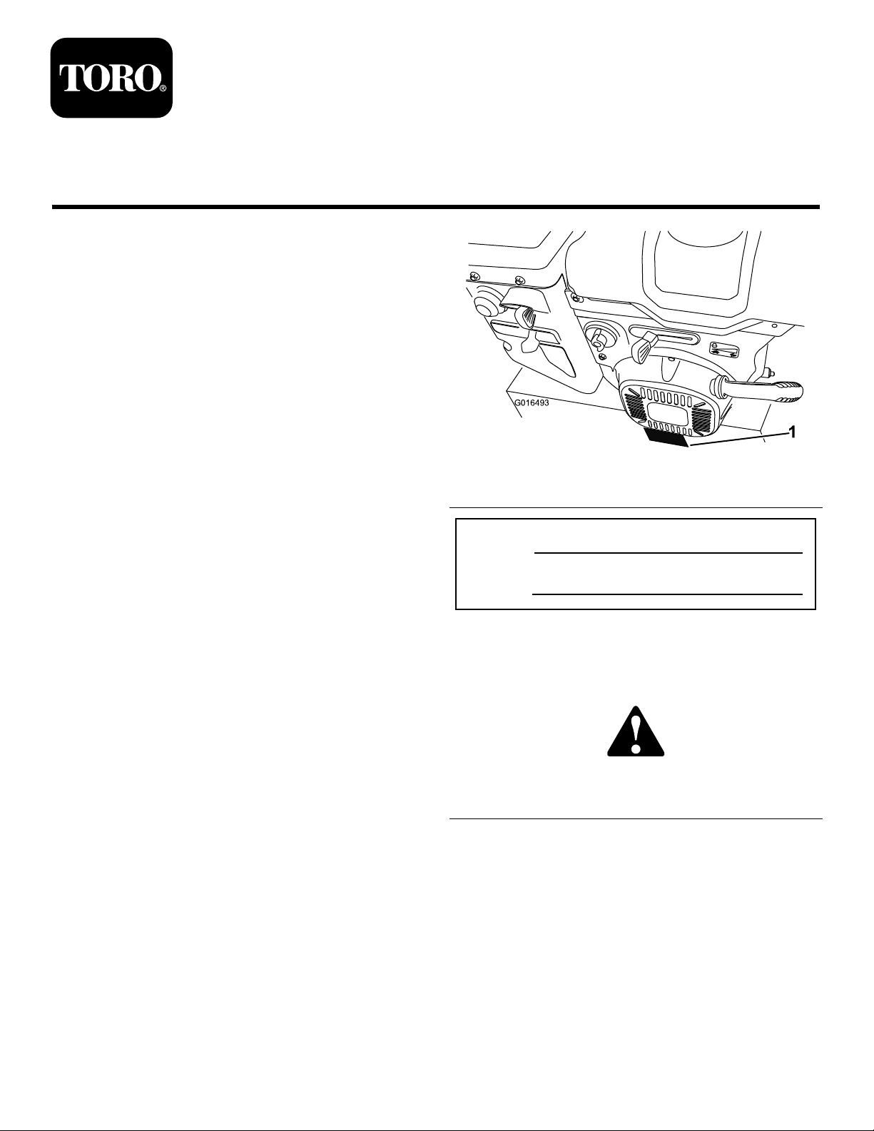
yourmachineready.Figure1identiesthelocationofthe
modelandserialnumbersonthemachine.Writethenumbers
inthespaceprovided.
FormNo.3373-560RevB
Operator'sManual
Figure1
1.Modelandserialnumberlocation
ModelNo.
SerialNo.
Thismanualidentiespotentialhazardsandhassafety
messagesidentiedbythesafetyalertsymbol(Figure2),
whichsignalsahazardthatmaycauseseriousinjuryordeath
ifyoudonotfollowtherecommendedprecautions.
©2012—TheT oro®Company
8111LyndaleAvenueSouth
Bloomington,MN55420
Figure2
1.Safetyalertsymbol
Thismanualuses2wordstohighlightinformation.
Importantcallsattentiontospecialmechanicalinformation
andNoteemphasizesgeneralinformationworthyofspecial
attention.
Registeratwww.T oro.com.
OriginalInstructions(EN)
PrintedintheUSA
AllRightsReserved
*3373-560*B
Page 2

ThissparkignitionsystemcomplieswithCanadianICES-002.
Contents
Introduction..................................................................1
Training.................................................................3
Preparation.............................................................3
Operation...............................................................3
ClearingaCloggedDischargeChute..........................4
MaintenanceandStorage..........................................4
ToroSnowthrowerSafety.........................................4
SafetyandInstructionalDecals.................................5
Setup............................................................................7
1InstallingtheUpperHandle....................................8
2InstallingtheWheelClutchCableEnds....................8
3InstallingtheTractionControlLinkage....................9
4InstallingtheChuteControlRod............................10
5ConnectingtheWiretotheHeadlight......................11
6FillingtheEnginewithOil.....................................11
7CheckingtheTirePressure....................................12
8CheckingtheSkidsandScraper..............................12
9CheckingtheTractionDriveOperation...................12
ProductOverview.........................................................14
Operation....................................................................14
FreewheelingorUsingtheSelf-propelDrive...............14
FillingtheFuelTank...............................................15
StartingtheEngine.................................................16
StoppingtheEngine...............................................18
OperatingtheTractionDrive...................................18
UsingtheWheelClutchLevers.................................18
OperatingtheSpeedSelector...................................19
OperatingtheAuger/ImpellerDrive.........................19
OperatingtheQuickStick®.....................................19
UncloggingtheDischargeChute..............................20
PreventingFreeze-up..............................................20
OperatingTips......................................................21
Maintenance.................................................................21
RecommendedMaintenanceSchedule(s)......................21
PreparingforMaintenance.......................................22
CheckingtheEngineOilLevel.................................22
CheckingandAdjustingtheSkids.............................22
CheckingandAdjustingtheTractionCable................23
CheckingandAdjustingtheAuger/Impeller
Cable................................................................23
CheckingtheAugerGearboxOilLevel......................24
ChangingtheEngineOil.........................................25
LubricatingtheHexShaft........................................25
ReplacingtheSparkPlug.........................................26
AdjustingtheDischargeChuteLatch........................26
ReplacingtheDriveBelts.........................................27
ReplacingtheHeadlightBulb...................................27
Storage........................................................................28
PreparingtheMachineforStorage............................28
RemovingtheMachinefromStorage.........................28
Troubleshooting...........................................................29
2
Page 3

Safety
ThismachinemeetsorexceedstheB71.3specications
oftheAmericanNationalStandardsInstituteineffect
atthetimeofproduction.
Readandunderstandthecontentsofthismanualbefore
theengineiseverstarted.
Thisisthesafetyalertsymbol.Itisusedtoalertyou
topotentialpersonalinjuryhazards.Obeyallsafety
messagesthatfollowthissymboltoavoidpossibleinjury
ordeath.
–Keepthenozzleincontactwiththerimofthefuel
tankorcontaineropeningatalltimes,untilrefueling
iscomplete.Donotuseanozzlelock-opendevice.
–Replacegasolinecapsecurelyandwipeupspilledfuel.
–Iffuelisspilledonclothing,changeclothing
immediately.
•Useextensioncordsandreceptaclesasspeciedby
themanufacturerforallmachineswithelectricstarting
motors.
•Adjustthecollectorhousingtocleargravelorcrushed
rocksurface.
Improperlyusingormaintainingthismachinecould
resultininjuryordeath.Toreducethispotential,
complywiththefollowingsafetyinstructions.
Training
•Read,understandandfollowallinstructionsonthe
machineandinthemanual(s)beforeoperatingthis
machine.Bethoroughlyfamiliarwiththecontrolsand
theproperuseofthemachine.Knowhowtostopthe
machineanddisengagethecontrolsquickly.
•Neverallowchildrentooperatethemachine.Neverallow
adultstooperatethemachinewithoutproperinstruction.
•Keeptheareaofoperationclearofallpersons,particularly
smallchildren.
•Exercisecautiontoavoidslippingorfalling,especially
whenoperatingthemachineinreverse.
Preparation
•Thoroughlyinspecttheareawherethemachineistobe
usedandremovealldoormats,sleds,boards,wires,and
otherforeignobjects.
•Disengageallclutchesandshiftintoneutralbefore
startingtheengine.
•Donotoperatethemachinewithoutwearingadequate
wintergarments.Avoidloosettingclothingthatcanget
caughtinmovingparts.W earfootwearthatwillimprove
footingonslipperysurfaces.
•Handlefuelwithcare;itishighlyammable.
–Useanapprovedfuelcontainer.
–Neveraddfueltoarunningengineorhotengine.
–Fillfueltankoutdoorswithextremecare.Neverll
fueltankindoors.
–Neverllcontainersinsideavehicleoronatruckor
trailerbedwithaplasticliner.Alwaysplacecontainers
ontheground,awayfromyourvehicle,beforelling.
–Whenpractical,removegas-poweredmachineryfrom
thetruckortrailerandrefuelitontheground.If
thisisnotpossible,thenrefuelsuchmachineryona
trailerwithaportablecontainer,ratherthanfroma
gasolinedispensernozzle.
•Neverattempttomakeanyadjustmentswhiletheengine
isrunning(exceptwhenspecicallyrecommendedby
manufacturer).
•Alwayswearsafetyglassesoreyeshieldsduringoperation
orwhileperforminganadjustmentorrepairtoprotect
eyesfromforeignobjectsthatmaybethrownfromthe
machine.
Operation
•Donotputhandsorfeetnearorunderrotatingparts.
Keepclearofthedischargeopeningatalltimes.
•Exerciseextremecautionwhenoperatingonorcrossing
graveldrives,walks,orroads.Stayalertforhidden
hazardsortrafc.
•Afterstrikingaforeignobject,stoptheengine,remove
theignitionkey ,thoroughlyinspectthemachineforany
damage,andrepairthedamagebeforerestartingand
operatingthemachine.
•Ifthemachineshouldstarttovibrateabnormally,stopthe
engineandcheckimmediatelyforthecause.Vibrationis
generallyawarningoftrouble.
•Stoptheenginewheneveryouleavetheoperating
position,beforeuncloggingtheauger/impellerhousing
ordischargechute,andwhenmakinganyrepairs,
adjustmentsorinspections.
•Whencleaning,repairingorinspectingthemachine,stop
theengineandmakecertaintheauger/impellerandall
movingpartshavestopped.Disconnectthesparkplug
wireandkeepthewireawayfromtheplugtoprevent
someonefromaccidentallystartingtheengine.
•Donotruntheengineindoors,exceptwhenstarting
theengineandfortransportingthemachineinorout
ofthebuilding.Opentheoutsidedoors;exhaustfumes
aredangerous.
•Exerciseextremecautionwhenoperatingonslopes.
•Neveroperatethemachinewithoutproperguards,and
othersafetyprotectivedevicesinplaceandworking.
•Neverdirectthedischargetowardpeopleorareaswhere
propertydamagecanoccur.Keepchildrenandothers
away.
3
Page 4
•Donotoverloadthemachinecapacitybyattemptingto
clearsnowattoofastarate.
•Neveroperatethemachineathightransportspeeds
onslipperysurfaces.Lookbehindandusecarewhen
operatinginreverse.
•Disengagepowertotheauger/impellerwhenmachineis
transportedornotinuse.
•Useonlyattachmentsandaccessoriesapprovedbythe
manufacturerofthemachine(suchaswheelweights,
counterweights,orcabs).
•Neveroperatethemachinewithoutgoodvisibilityor
light.Alwaysbesureofyourfooting,andkeeparm
holdonthehandles.Walk;neverrun.
•Nevertouchahotengineormufer.
ClearingaCloggedDischarge Chute
WARNING
Handcontactwiththerotatingrotorbladesinside
thedischargechuteisthemostcommoncauseof
injuryassociatedwithmachines.Neveruseyour
handtocleanoutthedischargechute.
Toclearthechute:
•Shuttheengineoff!
•Wait10secondstobesuretherotorbladeshavestopped
rotating.
•Alwaysusethecleanouttoolmountedonthe
snowthrower,notyourhands.
dischargeopeningwhileoperatingthemachine.Keep
yourface,hands,feet,andanyotherpartofyour
bodyorclothingawayfrommovingorrotatingparts.
•Beforeadjusting,cleaning,inspecting,troubleshooting,or
repairingthemachine,stoptheengine,removethekey,
andwaitforallmovingpartstostop.Disconnect
thewirefromthesparkplugandkeepitawayfrom
thesparkplugtopreventsomeonefromaccidentally
startingtheengine.
•Beforeleavingtheoperatingposition,stoptheengine,
removethekey,andwaitforallmovingpartstostop.
•Tounclogthedischargechute,stayintheoperating
positionandreleasethelefthand(traction)lever.While
runningtheauger/impeller,pushdownonthehandlesto
raisethefrontofthemachineafewinches(centimeters)
offthepavement.Thenliftthehandlesquicklytobump
thefrontofthemachineonthepavement.Repeatif
necessaryuntilastreamofsnowcomesoutthedischarge
chute.
•Ifyoucannotunclogthedischargechutebybumping
thefrontofthemachine,stoptheengine,waitfor
allmovingpartstostop,andusethecleanouttool;
neveruseyourhand.
•Ifashield,safetydevice,ordecalisdamaged,illegible,or
lost,repairorreplaceitbeforebeginningoperation.
•Donotsmokewhilehandlinggasoline.
•Donotusethemachineonaroof.
•Donottouchtheenginewhileitisrunningorsoonafter
ithasstoppedbecausetheenginemaybehotenoughto
causeaburn.
MaintenanceandStorage
•Checkallfastenersatfrequentintervalsforproper
tightnesstobesurethemachineisinsafeworking
condition.
•Neverstorethemachinewithfuelinthefueltankinsidea
buildingwhereignitionsourcesarepresentsuchashot
waterheaters,spaceheaters,orclothesdryers.Allowthe
enginetocoolbeforestoringinanyenclosure.
•AlwaysrefertotheOperator’ sManualforimportantdetails
ifthemachineistobestoredforanextendedperiod.
•Maintainorreplacesafetyandinstructionlabels,as
necessary.
ToroSnowthrowerSafety
ThefollowinglistcontainssafetyinformationspecictoToro
machinesorothersafetyinformationthatyoumustknow.
•Rotatingauger/impellercancutofforinjurengers
orhands.Staybehindthehandlesandawayfromthe
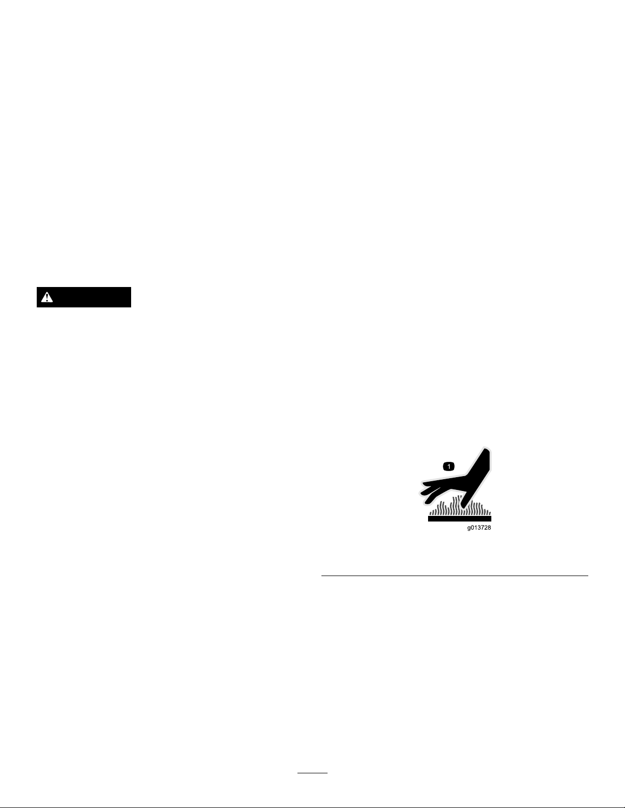
Figure3
1.Symbolstampedonthemuferheatshield
•Performonlythosemaintenanceinstructionsdescribedin
thismanual.Beforeperforminganymaintenance,service,
oradjustment,stoptheengine,removethekey,and
disconnectthewirefromthesparkplug.Ifmajorrepairs
areeverneeded,contactyourAuthorizedServiceDealer.
•Donotchangethegovernorsettingsontheengine.
•Whenstoringthemachineformorethan30days,drain
thefuelfromthefueltanktopreventapotentialhazard.
Storefuelinanapprovedfuelcontainer.Removethekey
fromtheignitionswitchbeforestoringthemachine.
•PurchaseonlygenuineTororeplacementpartsand
accessories.
4
Page 5
SafetyandInstructional
Decals
Important:Safetyandinstructiondecalsarelocated
nearareasofpotentialdanger.Replacedamageddecals.
107-3040
1.Cuttingdismemberment,impellerandcutting
dismemberment,augerhazards—keepbystandersasafe
distancefromthesnowthrower.
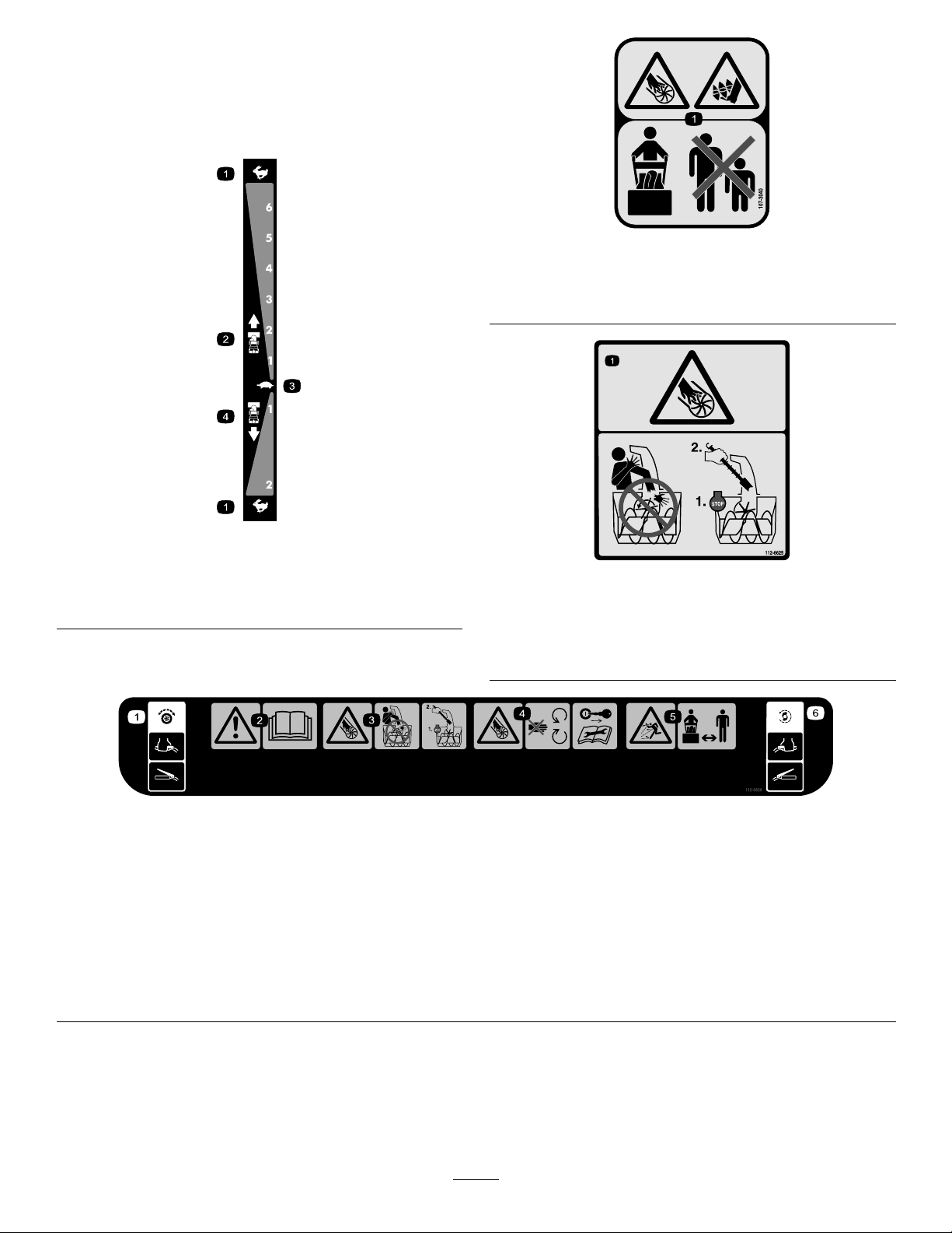
106-4525
Reorderpartno.1 12-6633
1.Fast
2.Forwardspeeds4.Reversespeeds
3.Slow
112-6626(Model38660only)
1.Tractiondrive—squeezetheleverto
engage;releasethelevertodisengage.
2.Warning—readtheOperator'sManual.4.Cutting/dismembermenthazard,
3.Cutting/dismembermenthazard,
impeller—donotplaceyourhandinthe
chute;stoptheenginebeforeleaving
theoperator'sposition,usethetoolto
clearthechute.
impellerandauger—stayawayfrom
movingparts,keepallguardsand
shieldsinplace;removetheignition
keyandreadtheinstructionsbefore
servicingorperformingmaintenance.
112-6625
Reorderpartno.1 12-6629
1.Cutting/dismembermenthazard,impeller—donotplace
yourhandinthechute;stoptheenginebeforeleavingthe
operator'sposition,usethetooltoclearthechute.
5.Thrownobjecthazard—keep
bystandersasafedistancefromthe
snowthrower.
6.Auger/impellerdrive—squeezethe
levertoengage;releasetheleverto
disengage.
5
Page 6
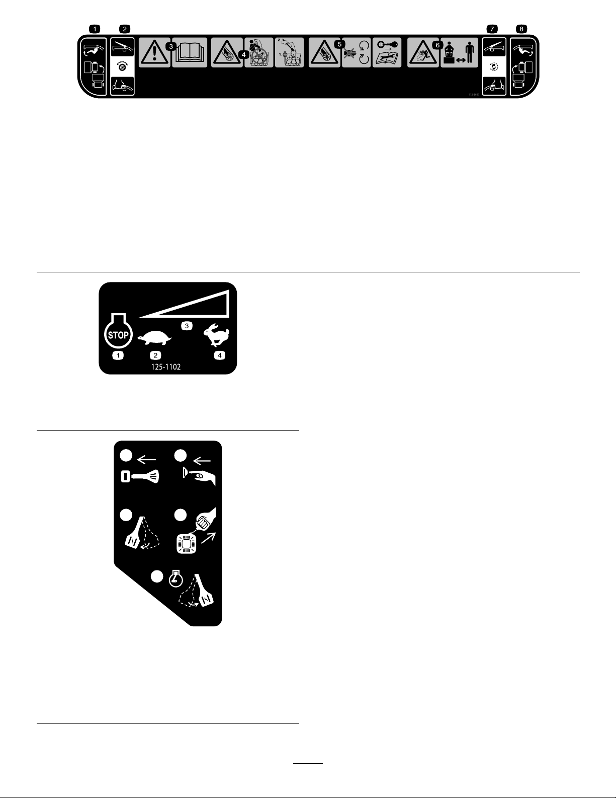
112-6627(Models38664and38674only)
x 3
1
2
3
4
5
120-9805
1.Leftturncontrol
2.Tractiondrive—squeeze
thelevertoengage;release
thelevertodisengage.
3.Warning—readthe
Operator'sManual.
4.Cutting/dismemberment
hazard,impeller—do
notplaceyourhand
inthechute;stopthe
enginebeforeleavingthe
operator'sposition,usethe
tooltoclearthechute.
125–1102
1.Enginestop3.Variablespeedcontrol
2.Slow
4.Fast
5.Cutting/dismemberment
hazard,impeller—keep
awayfrommovingparts;
removetheignitionkeyand
readtheinstructionsbefore
servicingorperforming
maintenance.
6.Thrownobject
hazard—keepbystanders
asafedistancefromthe
snowthrower.
7.Auger/impeller
drive—squeezetheleverto
engage;releasethelever
todisengage.
8.Rightturncontrol
1.Insertthekey.
2.Primetheengine3times.
3.Engagethechoke.
4.Pullthestartercord.
5.Oncetheengineisrunning,disengagethechoke.
120-9805
6
Page 7

Setup
LooseParts
Usethechartbelowtoverifythatallpartshavebeenshipped.
ProcedureDescription
1
2
3
4
5
6
7
8
9
Handlebolts4
Curvedwashers
Locknuts4
Nopartsrequired
Nopartsrequired
Carriagebolts
Locknuts2
Cabletie
Nopartsrequired
Nopartsrequired
Nopartsrequired
Nopartsrequired
Qty.
Use
4
–
–
2
1
–
–
–
–
Installtheupperhandle.
Installthewheelclutchcableends
Installthetractioncontrollinkage.
Installthechutecontrolrod.
Connectthewiretotheheadlight.
Filltheenginewithoil.
Checkthetirepressure.
Checktheskidsandscraper.
Checktheoperationofthetractiondrive.
7
Page 8
1
InstallingtheUpperHandle
Partsneededforthisprocedure:
4Handlebolts
4
Curvedwashers
4Locknuts
Procedure
Note:Donotremovetherubberbandonthecablesuntil
youhaveinstalledtheupperhandle.
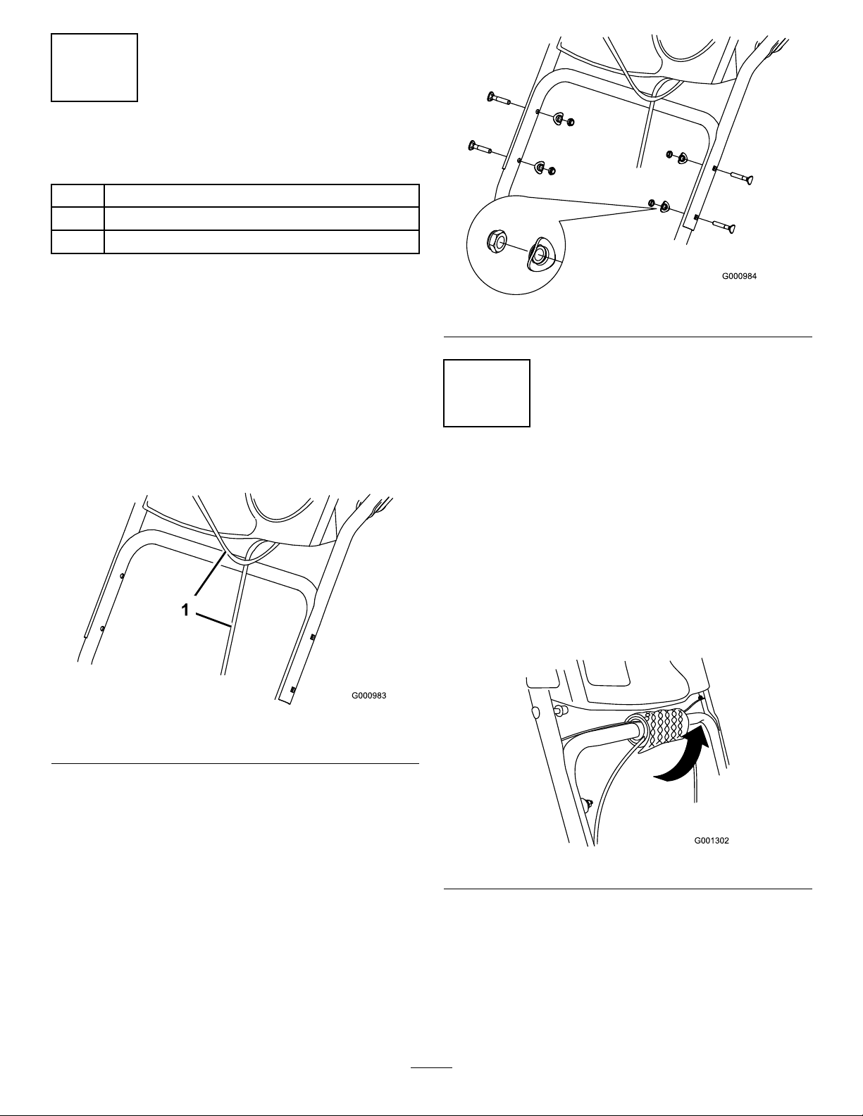
1.Liftandrotatetheupperhandleandpositionitover
thelowerhandle(Figure4).
Important:Routethecablesattachedtothe
QuickStickinsidetheupperhandlelegsand
ensurethatthecablesandthewireforthe
headlightarenotpinchedbetweenthehandle
sections.
Figure5
2
InstallingtheWheelClutch CableEnds
NoPartsRequired
Procedure
Models38664and38674only.
1.Unwrapthecableendsfromthelowerhandle
(Figure6).
Figure4
1.Cables
2.Securetheupperhandlewith4handlebolts,4curved
washers,and4locknutsfromtheloosepartsbag
Figure5).
(
Figure6
2.Routeeithertheleftorrightcableendoverthelower
handleandinsertthecableendintotheholeinthe
correspondingwheelclutchlever(Figure7).
8
Page 9
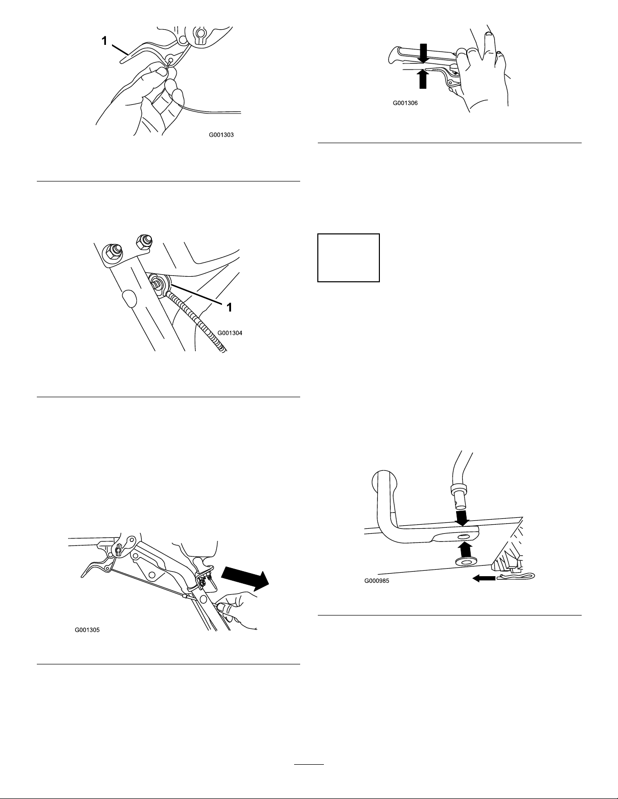
Figure7
1.Wheelclutchlever
3.Removethenutandwasherfromthehandle,attach
thecableclamponthecabletothehandle,installthe
washerandthenut,andhandtightenthenut(Figure8).
Figure8
Figure10
Note:Thegapshouldbeapproximatelythethickness
ofapencil(1/4inchor6mm).Ifitisgreater,loosen
thecableclampnut,slidethecablejacketupslightly,
tightenthecableclampnut,andcheckthegapagain.
6.Repeatsteps2through5fortheothercable.
3
InstallingtheTractionControl Linkage
NoPartsRequired
1.Cableclamp(2)
Important:Ensurethatthecurvedsideofthe
cableclampisagainstthehandleandthatthe
cableisroutedbelowtheclampbolt.Thecable
mustbeinastraightlinefromthecableclamp
tothepointwhereitattachestothewheelclutch
lever.
4.Pullthecablejacketdowngentlyuntilthewheelclutch
leverisdownandtheslackisoutofthecable,then
tightenthecableclampnutsecurely(Figure9).
Figure9
5.Squeezetheleverfully ,thencheckthegapbetweenthe
bottomofthehandleandthewheelclutchleverend
(Figure10).
Procedure
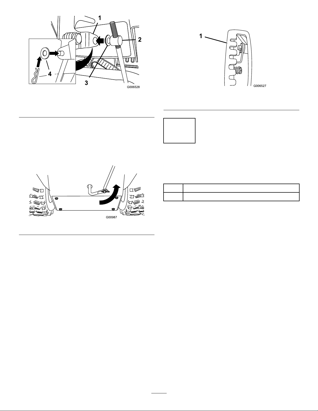
1.Removethehairpincotterandwasherfromthelower
endofthespeedcontrolrodandinsertthelowerend
oftherodintothelowerlinkarmsothatthebentend
ofthespeedcontrolrodfacesrearward(Figure11).
Figure11
2.Securethelowerendofthespeedcontrolrodwiththe
washerandhairpincotterthatyoupreviouslyremoved.
3.Removethehairpincotterandtheouterwasherfrom
thetrunnionontheupperendofthespeedcontrol
rod(Figure12).
9
Page 10
Note:Foreasierinstallation,lookdownthroughthe
openinginthespeedselector(Figure14).
Figure12
1.Speedselectorlever
2.Trunnion
Note:Tomakeinstallationeasier,leavetheatwasher
onthetrunnion(Figure12).
4.ShiftthespeedselectorleverintoPositionR2.
5.Rotatethelowerlinkarmfullyupward
(counterclockwise)(Figure13).
6.Liftuponthespeedcontrolrodandinsertthetrunnion
intotheholeinthespeedselectorlever(Figure12).
Note:Ifthetrunniondoesnottintothehole
whenyouliftuponthespeedcontrolrod,rotatethe
trunnionupwardordownwardonthespeedcontrol
roduntilitts.
7.Securethetrunnionandupperendofthespeedcontrol
rodwiththeouterwasherandahairpincotteryou
previouslyremoved.
3.Innerwasher
4.Outerwasher
Figure13
Figure14
1.Speedselector
4
InstallingtheChuteControl Rod
Partsneededforthisprocedure:
2
Carriagebolts
2Locknuts
Procedure
1.UnwraptheQuickStickandrotateitsothatitis
uprightandinthecenter.
2.Holdthebluetriggercapdownandpulltheleverfully
rearward.
Note:Thedischargechuteanddeectorshouldface
forward.Iftheydonot,holdthebluetriggercap
down(butdonotmovetheQuickStick)androtatethe
dischargechuteuntiltheydo.
3.Aligntheattenedbackendofthelongchutecontrol
rodwiththeattenedfrontendoftheshortrod
thatextendsfromthecontrolpanelsothattheynest
together(Figure15).
10
Page 11
g018656
Figure15
g018657
1
2
3
G016761
7.HoldthebluetriggercapdownandrotatetheQuick
Stickinacircletoensurethatthechuteanddeector
operatesmoothly.
5
ConnectingtheWiretothe Headlight
1.Shortrod
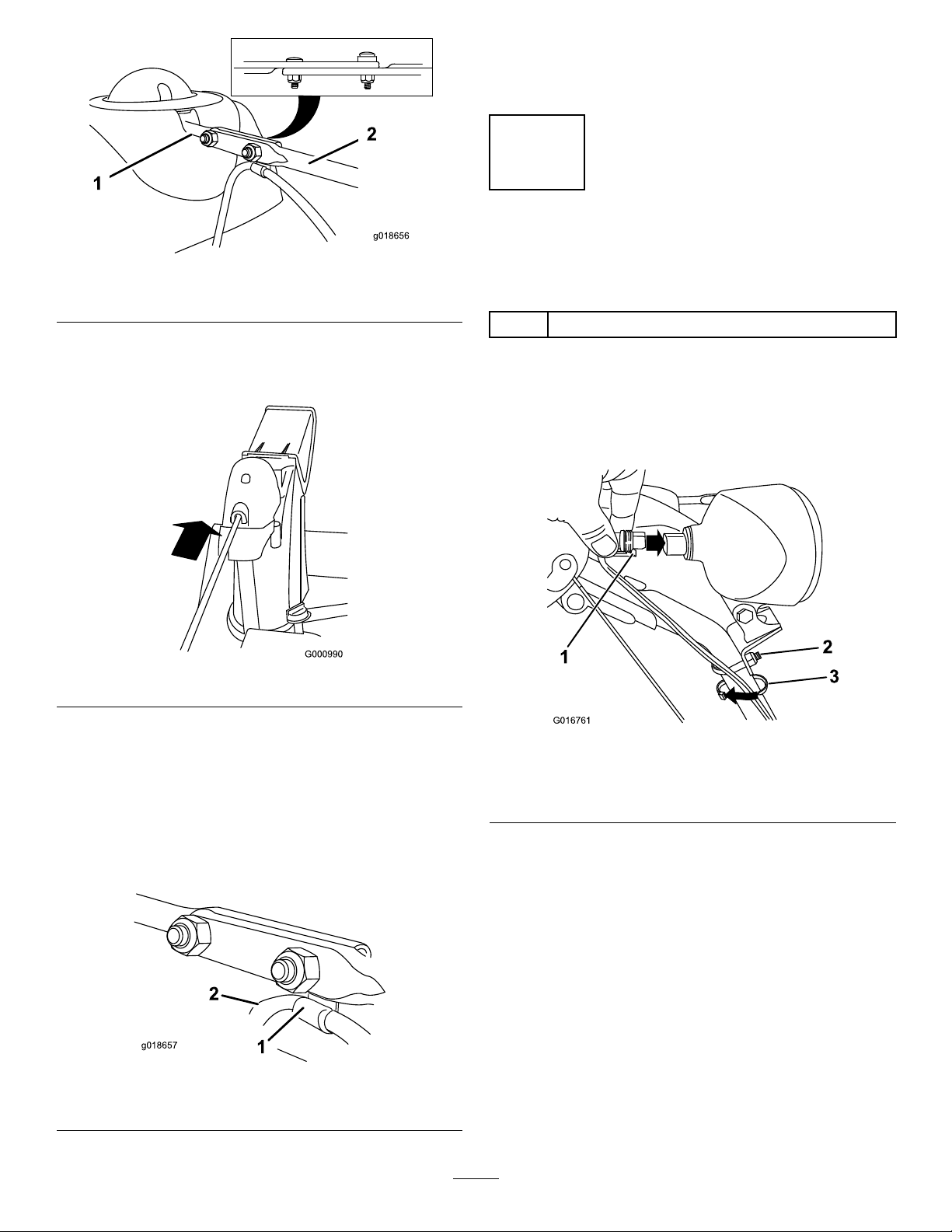
4.Insertthefrontendoftherodintotheopeningin
thebackofthechutegearcoveruntilitslidesintothe
chutegear(Figure16).
5.Aligntheholesinthenestedendsoftherodsand
insert2carriagebolts(intheloosepartsbag)through
theshortrodfromtheleftsideofthemachine(from
theoperatingposition).
6.Insertthecableclipthatsupportsthedeector
cableontotheforwardcarriagebolt,andsecurethe
carriageboltswithlocknutsfromtheloosepartsbag
(Figure17).
2.Longchutecontrolrod
Figure16
Partsneededforthisprocedure:
1
Cabletie
Procedure
1.Insertthewireconnectoronthelooseendofthewire
straightintothebackoftheheadlightuntilitissecurely
inplace(Figure18).
Figure18
1.Plasticcliponwire
connector
2.U-bolt
Note:Ensurethattheplasticcliponthewire
connectorisonthebottom(Figure18).
2.Secureacabletie(fromtheloosepartsbag)aroundthe
wireandthehandleaboutaninch(2.5cm)belowthe
U-bolt(Figure18).
3.Cabletie
Figure17
1.Cableclip2.Deectorcable
11
Page 12

6
G016497
1
2
FillingtheEnginewithOil
NoPartsRequired
Procedure
Yourmachinecomeswithoilintheenginecrankcase.
Note:Beforestartingtheengine,checktheoilleveland
addoilifnecessary.
UseautomotivedetergentoilwithanAPIserviceclassication
ofSF ,SG,SH,SJ,SL,orhigher.Refertoyourengineowner's
manual.
UseFigure19belowtoselectthebestoilviscosityforthe
outdoortemperaturerangeexpected:
Figure20
1.Full2.Addoil
2.Installthedipsticksecurelybypushingthecapdown
atandturning.
Note:Donotspilloilaroundtheoillltube;oilcould
leakontotractionpartsandcausethetractiontoslip.
Figure19
EngineOilCapacities
Model
38660
38664
38674
1.Removethedipstickbyrotatingthecap
counterclockwiseandslowlypouroilintotheoil
lltubetoraisetheoilleveltotheFullmarkonthe
dipstick.Donotoverll.(Figure20).
EngineOilCapacity
30to32oz.(0.89to0.95l)
7
CheckingtheTirePressure
NoPartsRequired
Procedure
Thetiresareoverinatedatthefactoryforshipping.Reduce
thepressureequallyinbothtirestobetween17and20psi
(116and137kPa).
8
CheckingtheSkidsand Scraper
NoPartsRequired
Procedure
RefertoCheckingandAdjustingtheSkidsandScraperin
Maintenance.
12
Page 13

9
CheckingtheTractionDrive
Operation
NoPartsRequired
4.Releasethetractionlever.
5.MovethespeedselectortothePositionF1;referto
OperatingtheSpeedSelector.
6.Squeezethelefthand(traction)levertothehand-grip
(
Figure21).
Themachineshouldmoveforward.Ifthemachine
doesnotmoveormovesrearward,completethe
following:
A.Releasethetractionleverandstoptheengine.
Procedure
CAUTION
Ifthetractiondriveisnotproperlyadjusted,the
machinemaymoveinthedirectionoppositeof
whatyouintended,causinginjuryand/orproperty
damage.
Carefullycheckthetractiondriveandadjustit
properly,ifnecessary .
Note:Model38660only—Tocheckthetractiondrive
operation,theself-propelfeaturemustbeengagedby
ensuringthewheelsarepinnedintheaxle.Referto
FreewheelingorUsingtheSelf-propelDrive(page14).
1.Starttheengine;refertoStartingtheEngine.
2.MovethespeedselectortoPositionR1;referto
OperatingtheSpeedSelector.
3.Squeezethelefthand(traction)levertothehand-grip
(Figure21).
B.Disconnectthetrunnionfromthespeedselector
Figure12).
lever(
C.Turnthetrunnionupward(counterclockwise)on
thespeedcontrolrod(Figure12).
D.Connectthetrunniontothespeedselectorlever
(Figure12).
7.Ifyoumadeanyadjustments,repeatthisprocedure
untilnoadjustmentsarerequired.
Important:Ifthemachinemoveswhenthetraction
leverisinthereleasedposition,checkthetractioncable
(refertoCheckingandAdjustingtheTractionCable)or
takethemachinetoanAuthorizedServiceDealerfor
service.
Figure21
Themachineshouldmoverearward.Ifthemachine
doesnotmoveormovesforward,completethe
following:
A.Releasethetractionleverandstoptheengine.
B.Disconnectthetrunnionfromthespeedselector
lever(Figure12).
C.Turnthetrunniondownward(clockwise)onthe
speedcontrolrod(
D.Connectthetrunniontothespeedselectorlever
Figure12).
(
Figure12).
13
Page 14

ProductOverview
G016495
ST
OP
1
2
3
4
5
6
7
G016500
g019015
g019014
Figure24
1.Snowcleanouttool(attachedtothehandle)
Operation
Note:Determinetheleftandrightsidesofthemachine
fromthenormaloperatingposition.
FreewheelingorUsingthe Self-propelDrive
Model38660only.
Youcanoperatethesnowthrowerwiththeself-propelfeature
engagedordisengaged(freewheeling).
Figure22
1.Hand-grip(2)10.Scraper
2.Auger/impellerlever
3.Speedselectorlever12.Skid(2)
4.QuickStick®discharge
chutecontrol
5.Tractionlever14.Electricstarterplug-in
6.Fueltankcap
7.Engineoillltube/dipstick
8.Chutedeector17.Wheelclutchlever(2)
9.Dischargechute
11.Auger
13.Electricstarterbutton
15.Snowcleanouttool
16.Headlight
Tofreewheel,inserttheaxlepinsthroughtheaxleholes,but
notthroughthewheelhubs(Figure25).
Figure25
Toself-propel,inserttheaxlepinsthroughtheholesinthe
wheelhubsandtheinneraxleholes(Figure26).
Figure26
1.Primer5.Throttle
2.Ignitionswitch
3.Choke
4.Fuelshutoffvalve
Figure23
6.Oildrainplug
7.Recoilstarter
14
Page 15

FillingtheFuelTank
g01881 1
DANGER
Gasolineisextremelyammableandexplosive.A
reorexplosionfromgasolinecanburnyouand
others.
•Topreventastaticchargefromignitingthe
gasoline,placethecontainerand/ormachine
onthegroundbeforelling,notinavehicleor
onanobject.
•Fillthetankoutdoorswhentheengineiscold.
Wipeupspills.
•Donothandlegasolinewhensmokingoraround
anopenameorsparks.
•Storegasolineinanapprovedfuelcontainer,out
ofthereachofchildren.
•Forbestresults,useonlyclean,fresh,unleadedgasoline
withanoctaneratingof87orhigher((R+M)/2rating
method).
•Oxygenatedfuelwithupto10%ethanolor15%MTBE
byvolumeisacceptable.
•DoNotuseethanolblendsofgasoline(suchasE15
orE85)withmorethan10%ethanolbyvolume.
Performanceproblemsand/orenginedamagemayresult
whichmaynotbecoveredunderwarranty.
•DoNotusegasolinecontainingmethanol.
•DoNotstorefueleitherinthefueltankorfuelcontainers
overthewinterunlessafuelstabilizerisused.
•DoNotaddoiltogasoline.
Important:Toreducestartingproblems,addfuel
stabilizertothefuelallseason,mixingitwithgasoline
lessthan30daysold.
Note:Neverusemethanol,gasolinecontainingmethanol,
orgasolinecontainingmorethan10%ethanolbecausethe
fuelsystemcouldbedamaged.
Do not add oil to the gasoline.
Figure27
1.Donotllabovethebottomofthefueltankneck.
15
Page 16

StartingtheEngine
G016512
1
G016498
G016494
1.Checktheengineoillevel.RefertoCheckingthe
EngineOilLevelinMaintenance.
2.Turnthefuelshutoffvalve1/4turncounterclockwise
toopenit(Figure28).
4.Firmlypushintheprimerwithyourthumbasindicated
bythechartbelow,holdingtheprimerinforasecond
beforereleasingiteachtime(Figure30).
Numberofprimes
3
4
6
Temperature
0°F(-18°C)orabove
-10°Fto0°F(-23°Cto-18°C)
-10°F(-23°C)andbelow
Figure28
3.Inserttheignitionkeyallthewayin(Figure29).
Figure29
Figure30
1.Ignitionkey
16
Page 17

5.MovethechoketotheChokeposition(Figure31).
G016501
STOP
G016504
g019055
Figure33
1.Electric-starterbutton3.Recoilstarter
2.Electricstarterplug-in
Note:Tousetheelectricstarter,connectapower
cordtotheelectricstarterplug-inrstandthentoa
poweroutlet.UseonlyaUL-listed,16-gaugeextension
cordrecommendedforoutdoorusethatisnotlonger
than50feet(15m).
Figure31
6.MovethethrottletotheFastposition(Figure32).
Figure32
7.Startthemachinebypullingtherecoilstarteror
pressingtheelectric-starterbutton(Figure33).
WARNING
Theelectricalcordcanbecomedamaged,
causingashockorre.
Thoroughlyinspecttheelectricalcordbefore
usingthemachine.Ifthecordisdamaged,
donotoperatethemachine.Replaceorrepair
thedamagedcordimmediately.Contactan
AuthorizedServiceDealerforassistance.
Important:Topreventdamagingtheelectric
starter,runitinshortcycles(5secondson,
5secondsoff),nomorethan10times.Ifthe
enginestilldoesnotstart,takethemachinetoan
AuthorizedServiceDealerforservice.
8.Disconnectthepowercordfromthepoweroutletrst
andthenfromthemachine(electricstartonly).
9.Allowtheenginetowarmup;graduallymovethe
choketowardtheRunposition.W aitfortheengineto
runsmoothlybeforeeachchokeadjustment.
CAUTION
Ifyouleavethemachinepluggedintoa
poweroutlet,someonecaninadvertentlystart
themachineandinjurepeopleordamage
property.
Unplugthepowercordwheneveryouarenot
startingthemachine.
17
Page 18

StoppingtheEngine
STOP
G016505
G016499
1.MovethethrottletotheSlowposition,andthentothe
Stopposition(Figure34)tokilltheengine.Theengine
canalsobestoppedbypullingtheignitionkeyoutward
tothemiddleposition.
Figure34
2.Waitforallmovingpartstostopbeforeleavingthe
operatingposition.
3.Removetheignitionkeytopreventaccidentalstarting.
OperatingtheTractionDrive
CAUTION
Ifthetractiondriveisnotproperlyadjusted,the
machinemaymoveinthedirectionoppositeof
whatyouintended,causinginjuryand/orproperty
damage.
Carefullycheckthetractiondriveandadjustit
properly,ifnecessary;refertoCheckingtheTraction
DriveOperationinSetupformoreinformation.
Important:Ifthemachinemoveswhenthetraction
leverisinthereleasedposition,checkthetractioncable
(refertoCheckingandAdjustingtheTractionCable)or
takethemachinetoanAuthorizedServiceDealerfor
service.
Important:T ooperatethetractiondrive,youmust
operatethemachinewiththeself-propelfeature
engaged.RefertoFreewheelingorUsingtheSelf-propel
Drive.
1.Toengagethetractiondrive,squeezethelefthand
(traction)levertothehandgrip(
Figure36).
4.Closethefuelshutoffvalvebyrotatingitclockwise
(Figure35).
Figure35
Figure36
2.Tostopthetractiondrive,releasethetractionlever.
UsingtheWheelClutchLevers
Thewheelclutchleversallowyoutomomentarilydisengage
thedrivetooneorbothwheelswiththetractiondrivelever
stillengaged.Thisenablesyoutoturnandmaneuverthe
machineeasily.
Note:Holdingdownthetractionleveragainstthehandle
engagesthetractiondrivetobothwheels.
Toturnthemachinetotheright,liftupontherightwheel
clutchleverandsqueezeittowardthehandle(Figure37).
5.Pulltherecoilstarter3or4times.Thishelpsprevent
therecoilstarterfromfreezingup.
18
Page 19

Figure37
Note:Thisdisengagesthedrivetotherightwheelwhile
theleftwheelcontinuesdriving,andthemachineturnsto
theright.
OperatingtheAuger/Impeller Drive
1.Toengagetheauger/impellerdrive,squeezethe
righthand(auger/impeller)levertothehandgrip
(Figure40).
Note:Similarly,squeezingtheleftwheelclutchleverturns
themachinetotheleft.
Whenyoucompletetheturn,releasethewheelclutchlever,
andthedrivere-engagesbothwheels(
Figure38
Momentarilysqueezingandreleasingtheleftorrightwheel
clutchleveralsoallowsforsteeringadjustmentstokeepthe
machinegoinginastraightline,especiallyindeepsnow.
Squeezingbothwheelclutchleverssimultaneouslydisengages
thedrivetobothwheels.Thisenablesyoutomanuallymove
themachinebackwardwithoutstoppingtoshiftitintoa
reversegear.Italsoallowsyoutomaneuverandtransportthe
machinemoreeasilywhentheengineisnotrunning.
Figure38).
OperatingtheSpeedSelector
Figure40
2.Tostoptheaugerandimpeller,releasetherighthand
lever.
Important:Whenyouengageboththe
auger/impellerleverandthetractionlever,the
tractionleverlockstheauger/impellerleverdown,
freeingyourrighthand.Toreleasebothlevers,
simplyreleasethelefthand(traction)lever.
3.Iftheaugerandimpellercontinuetorotatewhenyou
releasetheauger/impellerlever,donotoperatethe
machine.Checktheauger/impellercable(referto
CheckingandAdjustingtheAuger/ImpellerCable)
andadjustitifnecessary.Otherwise,takethemachine
toanAuthorizedDealerforservice.
WARNING
Iftheaugerandimpellercontinuetorotate
whenyoureleasetheauger/impellerlever,you
couldseriouslyinjureyourselforothers.
Donotoperatethemachine.Takeittoan
AuthorizedServiceDealerforservice.
Thespeedselectorhas6forwardand2reversegears.To
changespeeds,releasethetractionleverandshiftthespeed
selectorlevertothedesiredposition(Figure39).Thelever
locksinanotchateachspeedselection.
Figure39
OperatingtheQuickStick®
HoldthebluetriggercapdowntousetheQuickStickto
movethedischargechuteandthechutedeector.Releasethe
triggercaptolockthedischargechuteandchutedeector
intoposition(
19
Figure41).
Page 20

MovingtheDischargeChute
Figure41
Figure43
HoldthebluetriggercapdownandmovetheQuickStick
tothelefttomovethedischargechutetotheleft;movethe
QuickSticktotherighttomovethedischargechutetothe
right(
Figure42).
Figure42
•Ifthechutedoesnotmove,refertoAdjustingthe
DischargeChuteLatch.
•Ifthechutedoesnotturnasfartotheleftasitdoesto
theright,ensurethatthecableisroutedtotheinsideof
thehandles.RefertoInstallingtheUpperHandle.
UncloggingtheDischarge Chute
WARNING
Iftheauger/impellerisrunningbutthereisno
snowcomingoutofthedischargechute,the
dischargechutemaybeclogged.
Neveruseyourhandstoclearacloggeddischarge
chute.Thiscouldresultinpersonalinjury.
•Tounclogthedischargechute,stayintheoperating
positionandreleasethelefthand(traction)lever.While
runningtheauger/impeller,pushdownonthehandlesto
raisethefrontofthemachineafewinches(centimeters)
offthepavement.Thenliftthehandlesquicklytobump
thefrontofthemachineonthepavement.Repeatif
necessaryuntilastreamofsnowcomesoutthedischarge
chute.
•Ifyoucannotunclogthedischargechutebybumping
thefrontofthemachine,stoptheengine,waitforall
movingpartstostop,andusethesnowcleanouttool;
neveruseyourhand.
Important:Uncloggingthedischargechuteby
bumpingthefrontofthemachineonthepavement
maycausetheskidstomove.Adjusttheskidsand
tightentheskidboltssecurely.
•Ifthechutedoesnotlockintoplacewhenyoureleasethe
triggercap,refertoAdjustingtheDischargeChuteLatch.
MovingtheChuteDeector
HoldthebluetriggercapdownandmovetheQuickStick
forwardtolowerthechutedeector;moveitrearwardtoraise
thechutedeector(Figure43).
PreventingFreeze-up
•Insnowyandcoldconditions,somecontrolsandmoving
partsmayfreeze.Donotuseexcessiveforcewhen
tryingtooperatefrozencontrols.Ifyouhavedifculty
operatinganycontrolorpart,starttheengineandletit
runforafewminutes.
•Afterusingthemachine,lettheenginerunforafew
minutestopreventmovingpartsfromfreezing.Engage
theauger/impellertoclearanyremainingsnowfrom
insidethehousing.RotatetheQuickSticktopreventit
20
Page 21

fromfreezing.Stoptheengine,waitforallmovingparts
tostop,andremovealliceandsnowfromthemachine.
•Withtheengineoff,pulltherecoilstarterhandleseveral
timesandpushtheelectric-starterbuttononcetoprevent
therecoilstarterandelectricstarterfromfreezingup.
OperatingTips
DANGER
WARNING
Theimpellercanthrowstones,toys,andother
foreignobjectsandcauseseriouspersonalinjuryto
theoperatorortobystanders.
•Keeptheareatobeclearedfreeofallobjects
thattheaugerscouldpickupandthrow.
•Keepallchildrenandpetsawayfromthearea
ofoperation.
Whenthemachineisinoperation,theimpellerand
augercanrotateandcutofforinjurehandsandfeet.
•Beforeadjusting,cleaning,inspecting,
troubleshooting,orrepairingthemachine,stop
theengineandwaitforallmovingpartstostop.
Disconnectthewirefromthesparkplugand
keepitawayfromtheplugtopreventsomeone
fromaccidentallystartingtheengine.
•Removeanobstructionfromthedischarge
chute;refertoUncloggingtheDischargeChute.
Ifnecessary ,usethesnowcleanouttool,not
yourhands,toremoveanobstructionfromthe
dischargechute.
•Staybehindthehandlesandawayfromthe
dischargeopeningwhileoperatingthemachine.
•Keepface,hands,feet,andanyotherpartof
yourbodyorclothingawayfromconcealed,
moving,orrotatingparts.
Maintenance
•AlwayssetthethrottletotheFastpositionwhenthrowing
snow .
•Iftheengineslowsdownunderaloadorthewheelsslip,
shiftthemachineintoalowergear.
•Ifthefrontofthemachineridesup,shiftthemachine
intoalowergear.Ifthefrontcontinuestorideup,liftup
onthehandles.
Note:Determinetheleftandrightsidesofthemachinefromthenormaloperatingposition.
RecommendedMaintenanceSchedule(s)
MaintenanceService
Interval
Aftertherst2hours
Aftertherst5hours
Beforeeachuseordaily
Every50hours
Every100hours
MaintenanceProcedure
•Inspectthetractioncableandadjustitifnecessary.
•Inspecttheauger/impellercableandadjustitifnecessary .
•Changetheengineoil.
•Checktheengineoillevelandaddoilifnecessary.
•Changetheengineoil.Changetheengineoilevery25operatinghourswhen
operatingtheengineunderaheavyload.
•Replacethesparkplug.
21
Page 22

MaintenanceService
G016497
1
2
Interval
Yearly
Yearlyorbeforestorage
Important:Youcanndmoreinformationaboutmaintainingandservicingyourmachineatwww .T oro.com.
MaintenanceProcedure
•Checktheskidsandadjustthemifnecessary.
•Inspectthetractioncableandadjustorreplaceitifnecessary.
•Inspecttheauger/impellercableandadjustorreplaceitifnecessary.
•Checktheaugergearboxoilandaddoilifnecessary.
•Lubricatethehexshaft.
•Checktheairpressureinthetiresandinatethemto17–20psi(116–137kPa).
•Runtheenginetodryoutthefueltankandthecarburetorattheendoftheseason.
•HaveanAuthorizedServiceDealerinspectandreplacethetractiondrivebeltand/or
theauger/impellerdrivebelt,ifnecessary.
PreparingforMaintenance
1.Movethemachinetoalevelsurface.
2.Stoptheengineandwaitforallmovingpartstostop.
3.Disconnectthesparkplugwire.RefertoReplacing
theSparkPlug.
CheckingtheEngineOilLevel
ServiceInterval:Beforeeachuseordaily—Checktheengine
oillevelandaddoilifnecessary.
1.Removethedipstick,wipeitclean,thenfullyinstall
thedipstick.
2.Removethedipstickandchecktheoillevel(Figure44).
IftheoillevelisbelowtheAddmarkonthedipstick,
addoil.RefertoFillingtheEnginewithOil.
CheckingandAdjustingthe Skids
ServiceInterval:Yearly—Checktheskidsandadjustthem
ifnecessary.
Checktheskidstoensurethattheaugerdoesnotcontact
thepavedorgravelsurface.Adjusttheskidsasneededto
compensateforwear.
1.Checkthetirepressure.RefertoCheckingtheTire
Pressure.
2.Loosenthenutsthatsecurebothskidstotheauger
sidesuntiltheskidsslideupanddowneasily(Figure45).
Figure45
Figure44
1.Full2.Addoil
1.1/2inch(1.3cm)
3.Supportthesideplatessothattheyareatleast1/2
inch(1.3cm)abovealevelsurface.
Important:Theaugerbladesmustbesupported
abovethegroundbytheskids.
4.Ensurethatthescraperis1/8inch(3mm)aboveand
paralleltoalevelsurface.
Note:Ifthepavementiscracked,rough,oruneven,
adjusttheskidstoraisethescraper.Forgravelsurfaces,
adjusttheskidsfurtherdowntopreventthemachine
frompickinguprocks.
5.Movetheskidsdownuntiltheyareevenwiththe
ground.
6.Firmlytightenthenutsthatsecurebothskidstothe
augersides.
22
Page 23

Note:Toquicklyadjusttheskidsiftheyloosen,
supportthescraper1/8inch(3mm)offthepavement,
thenadjusttheskidsdowntothepavement.
Note:Iftheskidsbecomeexcessivelyworn,youcan
turnthemoverandsettheunusedsidetowardthe
pavement.
CheckingandAdjustingthe TractionCable
ServiceInterval:Aftertherst2hours—Inspectthe
tractioncableandadjustitifnecessary.
Yearly—Inspectthetractioncableand
adjustorreplaceitifnecessary.
Figure47
1.Jamnut2.Turnbuckle
Ifthemachinedoesnotdriveintheforwardorreversespeeds
oritdriveswhenyoureleasethetractionlever,adjustthe
tractioncable.
Withthetractionleverdisengaged,checkthepininthe
elongatedslotintheleftsideofthemachineabovethe
tire.Thereshouldbeagapof1/32to1/16inch(1to1.5
mm)fromthefrontoftheslottothefrontedgeofthepin
(Figure46).
Figure46
1.Pin
2.1/32to1/16inch(1to1.5mm)
CheckingandAdjustingthe Auger/ImpellerCable
ServiceInterval:Aftertherst2hours—Inspectthe
auger/impellercableandadjustitif
necessary.
Yearly—Inspecttheauger/impellercable
andadjustorreplaceitifnecessary.
1.Removethe2screwsfromtherightsideofthebelt
coverasshown.
2.Liftuptherightsideofthebeltcover(Figure48).
Figure48
Ifthelefthand(traction)cableisnotproperlyadjusted,do
thefollowingsteps:
1.Loosenthejamnut.
2.Loosenortightentheturnbuckletoadjustthepinuntil
itisthepropergapfromthefrontedgeoftheslot.
3.Tightenthejamnut(
Figure47).
3.Withtheauger/impellerleverdisengaged,ensurethat
thegapbetweentheaugerclutchassemblyandthetab
is1/16inch(1.5mm)(
23
Figure49).
Page 24

Figure49
1
G016782
1.Movethemachinetoalevelsurface.
2.Cleantheareaaroundthepipeplug(Figure51).
1.Tab
2.1/16inch(1.5mm)
4.Iftheauger/impellercableisnotproperlyadjusted,do
thefollowingsteps:
5.Loosenthejamnut(Figure50).
Figure50
Figure51
1.Pipeplug
3.Removethepipeplugfromthegearbox.
4.Checktheoillevelinthegearbox.Theoilshouldbeat
thepointofoverowingatthelleropening.
5.Iftheoillevelislow ,addGL-5orGL-6,SAE85-95
EPgearoillubricanttothegearboxuntilthepointof
overow .
Note:Donotusesyntheticoil.
6.Installthepipepluginthegearbox.
1.Jamnut2.Turnbuckle
6.Loosenortightentheturnbucklethatadjuststhe
tensiononthecable(Figure50).
7.Adjusttheturnbuckleuntilyouobtainthepropergap.
8.Tightenthejamnut.
9.Insertthe2screwsyoupreviouslyremovedonthebelt
cover.
10.Iftheauger/impellercableisproperlyadjustedbut
aproblemremains,contactanAuthorizedService
Dealer.
CheckingtheAugerGearbox OilLevel
ServiceInterval:Yearly—Checktheaugergearboxoiland
addoilifnecessary.
24
Page 25

ChangingtheEngineOil
G016496
1
ServiceInterval:Aftertherst5hours—Changetheengine
oil.
Every50hours—Changetheengineoil.
Changetheengineoilevery25operating
hourswhenoperatingtheengineundera
heavyload.
Ifpossible,runtheenginejustbeforechangingtheoilbecause
warmoilowsbetterandcarriesmorecontaminants.
UseautomotivedetergentoilwithanAPIserviceclassication
ofSF ,SG,SH,SJ,SL,orhigher.Refertoyourengineowner's
manual.
2.Slideanoildrainpanunderthedrainextensionand
removetheoildrainplug.
Note:Whenremovingtheplug,ensurethetubedoes
notloosen.
3.Draintheoil.
Note:Disposeoftheusedoilproperlyatalocal
recyclingcenter.
4.Installtheoildrainplug.
5.Fillthecrankcasewithoil.RefertoFillingtheEngine
CrankcasewithOil.
Use
Figure52belowtoselectthebestoilviscosityforthe
outdoortemperaturerangeexpected:
Figure52
EngineOilCapacities
Model
38660
38664
38674
EngineOilCapacity
30to32oz.(0.89to0.95l)
LubricatingtheHexShaft
ServiceInterval:Yearly—Lubricatethehexshaft.
Lightlylubricatethehexshaftyearlywithautomotiveengine
oil(Figure54).
Figure54
1.Hexshaft
2.Aluminumfrictionplate
Important:Donotgetoilontherubberwheelorthe
aluminumfrictiondriveplatebecausethetractiondrive
willslip(
Figure54).
3.Rubberwheel
1.Cleantheareaaroundtheoildraincap(Figure53).
Figure53
1.Oildrainplug
1.Drainthegasolinefromthefueltank.
2.Tipthemachineforwardontoitsaugerhousingand
blockitsothatitcannotfall.
3.Removethebackcover(
1.Backcover
Figure55).
Figure55
4.MovethespeedselectorlevertoPositionR2.
25
Page 26

5.Dipyourngerinautomotiveengineoilandlightly
G016645
1
G016646
lubricatehexshaft.
6.MovethespeedselectorlevertoPosition6.
7.Lubricatetheotherendofthehexshaft.
8.Movethespeedselectorleverforwardandrearward
afewtimes.
9.Installthebackcoverandreturnthemachinetothe
operatingposition.
ReplacingtheSparkPlug
ServiceInterval:Every100hours—Replacethesparkplug.
WARNING
Figure57
Replacingthesparkplugwhiletheengineishot
canresultinburns.
Waituntiltheengineiscooltoreplacethespark
plug.
UseaT orosparkplugorequivalent(Champion®RN9YCor
NGKBPR6ES).
1.Removetheboot(
1.Sparkplugboot
Figure56).
Figure56
3.Removeanddiscardtheoldsparkplug.
Note:Youwillneedaratchetwrenchextensionto
removethesparkplug.
4.Setthegapbetweentheelectrodesonanewsparkplug
at0.030inch(0.76mm)(Figure58).
Figure58
1.0.030inch(0.76mm)
5.Installthenewsparkplug,tightenitrmly,andattach
theignitionwiretothesparkplug.
Note:Ensuretheignitionwiresnapscompletelyinto
placeonthesparkplug.
2.Cleanaroundthebaseofthesparkplug.
AdjustingtheDischargeChute Latch
Ifthedischargechutedoesnotlockintothedesiredposition
ordoesnotunlocksothatyoucanmoveittoanother
position,adjustthedischargechutelatch.
1.Removethefasteneronthegearcover(
thefrontofthecoverup,andslideitbackandoutof
theway.
26
Figure59),lift
Page 27

ReplacingtheDriveBelts
Iftheauger/impellerdrivebeltorthetractiondrivebelt
becomesworn,oil-soaked,orotherwisedamaged,havean
AuthorizedServiceDealerreplacethebelt.
ReplacingtheHeadlightBulb
Figure59
2.Loosentheboltonthecableclamp(Figure60).
Figure60
1.Cableconduit2.Cableclamp
3.Graspthecableconduitandmoveittowardthefront
ofthemachineuntilthedischargechutelatchfully
engagesthegearteeth(Figure60andFigure61).
UseaGE89937Whalogenlightbulb.Donottouchthe
bulbwithyourhandsorallowdirtormoisturetocomeinto
contactwiththebulb.
1.Removethewireconnectorfromthebackofthe
headlight(Figure62).
Figure62
2.Turnthebaseofthebulbcounterclockwiseuntilit
stops(Figure63).
Figure61
1.Dischargechutelatch
Note:Thelatchisspringloadedandwillnaturally
moveintotheteethofthegear(Figure61).
4.Removeanyslackinthecablebypullingthecable
conduitrearward.
5.Tightentheboltonthecableclamp,beingcarefulnot
tostriptheplasticpart.
6.Installandsecurethegearcover.
2.Gearteeth
Figure63
3.Removethebulbstraightoutfromthebackofthe
headlight(Figure64).
Figure64
4.Insertanewbulbintothebackoftheheadlight
(Figure65).
27
Page 28

Storage
WARNING
•Gasolinevaporscanexplode.
Figure65
5.Turnthebaseofthebulbclockwiseuntilitissnug
(Figure66).
Figure66
6.Insertthewireconnectorstraightintothebackofthe
headlightuntilitissecurelyinplace(Figure67).
•Donotstoregasolinemorethan30days.
•Donotstorethemachineinanenclosurenear
anopename.
•Allowtheenginetocoolbeforestoringit.
PreparingtheMachinefor Storage
1.Onthelastrefuelingoftheyear,addfuelstabilizerto
freshfuel.
Note:Fuelshouldnotbestoredlongerthansuggested
bythefuelstabilizermanufacturer.
2.Runtheenginefor10minutestodistributethe
conditionedfuelthroughthefuelsystem.
3.Runthemachineuntiltheenginerunsoutoffuel.
4.Primetheengineandstartitagain.
5.Allowtheenginetorununtilitstops.Whenyoucan
nolongerstarttheengine,itissufcientlydry.
6.Stoptheengineandallowittocool.
Figure67
7.Removetheignitionkey.
8.Cleanthemachinethoroughly.
9.Touchupchippedsurfaceswithpaintavailablefroman
AuthorizedServiceDealer.Sandaffectedareasbefore
painting,andusearustpreventativetopreventthe
metalpartsfromrusting.
10.Tightenallloosescrews,bolts,andlocknuts.Repairor
replaceanydamagedparts.
11.Coverthemachineandstoreitinaclean,dryplaceout
ofthereachofchildren.
RemovingtheMachinefrom Storage
Performtheannualmaintenanceproceduresasgiveninthe
RecommendedMaintenanceSchedule.
28
Page 29

Troubleshooting
Problem
Electricstarterdoesnotturn(electric-start
modelsonly)
Enginedoesnotstartorstartshard
PossibleCauseCorrectiveAction
1.Thepowercordisdisconnectedatthe
outletorthemachine.
2.Thepowercordisworn,corroded,or
damaged.
3.Thepoweroutletisnotenergized.
1.Thekeyisnotintheignitionorisinthe
Stopposition.
2.ThechokeisintheOffpositionandthe
primerhasnotbeenpressed.
3.Thefuelshutoffvalveisnotopen.3.Openthefuelshutoffvalve.
4.ThethrottleisnotintheFastposition.4.MovethethrottletotheFastposition.
5.Thefueltankisemptyorthefuel
systemcontainsstalefuel.
6.Thesparkplugwireislooseor
disconnected.
7.Thesparkplugispitted,fouled,orthe
gapisincorrect.
8.Thefuelventcapisrestricted.
9.Theengineoillevelintheengine
crankcaseistoolowortoohigh.
1.Connectthepowercordtotheoutlet
and/orthemachine.
2.Replacethepowercord.
3.Haveaqualiedelectricianenergize
theoutlet.
1.Insertthekeyintotheignitionandturn
ittotheOnposition.
2.MovethechoketotheOnpositionand
presstheprimer3times.
5.Drainand/orllthefueltankwithfresh
gasoline(notmorethan30daysold).
Iftheproblempersists,contactan
AuthorizedServiceDealer.
6.Connectthewiretothesparkplug.
7.Checkthesparkplugandadjustthe
gapifnecessary .Replacethespark
plugifitispitted,fouled,orcracked.
8.Removetheventrestrictionorreplace
thefuelcap.
9.Addordrainoiltoadjusttheoillevelin
theenginecrankcasetotheFullmark
onthedipstick.
Enginerunsrough
1.ThechokeisintheOnposition.1.MovethechoketotheOffposition.
2.Thefuelshutoffvalveisnotcompletely
open.
3.Thefueltankisnearlyemptyor
containsstalefuel.
4.Thesparkplugwireisloose.
5.Thesparkplugispitted,fouled,orthe
gapisincorrect.
6.Theengineoillevelintheengine
crankcaseistoolowortoohigh.
2.Openthefuelshutoffvalve.
3.Drainandllthefueltankwithfresh
gasoline(notmorethan30daysold).
Iftheproblempersists,contactan
AuthorizedServiceDealer.
4.Connectthewiretothesparkplug.
5.Checkthesparkplugandadjustthe
gapifnecessary .Replacethespark
plugifitispitted,fouled,orcracked.
6.Addordrainoiltoadjusttheoillevelin
theenginecrankcasetotheFullmark
onthedipstick.
29
Page 30

Problem
PossibleCauseCorrectiveAction
Engineruns,butthemachinedischarges
snowpoorlyornotatall
Dischargechuteeitherdoesnotlockinto
placeordoesnotmove
Themachinedoesnotproperlyclearthe
snowoffthesurface
1.ThethrottleisnotintheFastposition
whenthrowingsnow .
2.Themachineismovingtoofasttoclear
thesnow.
3.Youaretryingtoremovetoomuch
snowperswath.
4.Youaretryingtoremoveextremely
heavyorwetsnow.
5.Thedischargechuteisplugged.5.Unclogthedischargechute.
6.Theauger/impellerdrivebeltisloose
orisoffthepulley .
7.Theauger/impellerdrivebeltisworn
orbroken.
1.Thedischargechutelatchisnot
properlyadjusted.
1.Theskidsand/orscraperarenot
properlyadjusted.
2.Thepressureinthetiresisnotequal.
1.MovethethrottletotheFastposition.
2.Shiftthemachineintoalowergear.
3.Reducetheamountofsnowremoved
perswath.
4.Don'toverloadthemachinewith
extremelyheavyorwetsnow.
6.Installand/oradjusttheauger/impeller
drivebelt;refertowww.Toro.com
forservicinginformationortakethe
machinetoanAuthorizedService
Dealer.
7.Replacetheauger/impellerdrivebelt;
refertowww.Toro.comforservicing
informationortakethemachinetoan
AuthorizedServiceDealer.
1.Adjustthedischargechutelatch.
1.Adjusttheskidsand/orthescraper.
2.Checkandadjustthepressureinone
orbothtires.
30
Page 31

Notes:
31
Page 32

Notes:
32
Page 33

Notes:
33
Page 34

EmissionControlWarrantyStatement
FortheUnitedStates,California,andCanada
TheCaliforniaAirResourcesBoard(CARB),theU.S.EnvironmentalProtectionAgency(EPA),andTheT oroCompany,arepleasedtoexplainthe
emissioncontrolsystemwarrantyonyour2012–2013smalloff-roadengine/equipment.InCaliforniaandtheUnitedStates,newsmalloff-road
engines/equipmentmustbedesigned,built,andcertiedtomeetstringentanti-smogstandards.TheT oroCompanywarrantstheemissioncontrol
systemonyoursmalloff-roadengine/equipmentfortheperiodoftimelistedabove,providedtherehasbeennoabuse,neglect,orimpropermaintenance
ofyoursmalloff-roadengine/equipment.
Youremissioncontrolsystemmayincludepartssuchasthecarburetor,fuel-injectionsystem,theignitionsystem,catalyticconverter,fueltanks,fuellines,
fuelcaps,valves,canisters,lters,vaporhoses,clamps,connectors,andotherassociatedemission-relatedcomponents.
Whereawarrantableconditionexists,TheT oroCompanywillrepairyoursmalloff-roadengine/equipmentatnocosttoyouincludingdiagnosis,
partsandlabor.
TheToroCompanyanditsafliate,T oroWarrantyCompany ,pursuanttoanagreementbetweenthem,jointlywarrantthe2012–2013smalloff-road
engine/equipmentfortwoyearsfromthedateofdelivery.Ifanyemission-relatedpartonyourengine/equipmentisdefective,thepartwillberepairedor
replacedbyTheT oroCompany.
Asthesmalloff-roadengineowner,youareresponsiblefortheperformanceoftherequiredmaintenancelistedinyourOperator'sManual.Werecommend
thatyouretainallreceiptscoveringmaintenanceonyoursmalloff-roadengine/equipment,butwecannotdenywarrantysolelyforthelackofreceipts.
Asthesmalloff-roadengine/equipmentowner,youshouldhoweverbeawarethatwemaydenyyouwarrantycoverageifyoursmalloff-road
engine/equipmentoraparthasfailedduetoabuse,neglect,impropermaintenanceorunapprovedmodications.
Youareresponsibleforpresentingyoursmalloff-roadengine/equipmenttoanAuthorizedServiceDealerassoonasaproblemexists.Thewarranty
repairsshouldbecompletedinareasonableamountoftime,nottoexceedthirty(30)days.
Ifyouhaveanyquestionsregardingyourwarrantycoverage,contactusat:
CustomerCareDepartment,ConsumerDivision
ToroWarrantyCompany
811 1LyndaleAvenueSouth
Bloomington,MN55420-1196
Tollfreeat800–348–2424(U.S.customers)
Tollfreeat800–544–5364(Canadiancustomers)
ATwo-YearLimitedWarranty
YourWarrantyRightsandObligations
Manufacturer’sWarrantyCoverage
OwnerResponsibilities
GeneralEmissionsWarrantyCoverage
TheT oroCompanyanditsafliate,T oroWarrantyCompany,jointlywarranttotheinitial
ownerandeachsubsequentpurchaserthatthesmalloff-roadengine/equipmentis:
•Designed,built,andcertiedtoconformwithallapplicableemissionsregulations;and
•Freefromdefectsinmaterialsandworkmanshipthatcouldcausethefailureofawarrantedpart;and
•Identicalinallmaterialrespectstothepartsasdescribedintheapplicationforcertication.
Thewarrantyperiodbeginsonthedatethesmalloff-roadengine/equipmentisdeliveredtoanultimatepurchaser.Thewarrantedperiodistwoyears.
Subjecttocertainconditionsandexclusionsasstatedbelow,thewarrantyonevaporativeemissions-relatedpartsisasfollows:
1.Anywarrantedpartthatisnotscheduledforreplacementasrequiredmaintenanceinthewritteninstructionssupplied,iswarranted
forthewarrantyperiodstatedabove.Ifthepartfailsduringtheperiodofwarrantycoverage,thepartwillberepairedorreplacedby
TheT oroCompany.Anysuchpartrepairedorreplacedunderwarrantywillbewarrantedfortheremainderofthewarrantyperiod.
2.Anywarrantedpartthatisscheduledonlyforregularinspectioninthewritteninstructionssuppliediswarrantedforthewarranty
periodstatedabove.Anysuchpartrepairedorreplacedunderthewarrantywillbewarrantedfortheremainderofthewarrantyperiod.
3.Anywarrantedpartthatisscheduledforreplacementasrequiredmaintenanceinthewritteninstructionssuppliedis
warrantedfortheperiodoftimebeforetherstscheduledreplacementdateforthatpart.Ifthepartfailsbeforetherst
scheduledreplacement,thepartwillberepairedorreplacedbyTheToroCompany .Anysuchpartrepairedorreplaced
underwarrantywillbewarrantedfortheremainderoftheperiodpriortotherstscheduledreplacementpointforthepart.
4.Repairorreplacementofanywarrantedpartunderthewarrantyprovisionshereinmustbeperformedatan
AuthorizedServiceDealeratnochargetotheowner.
5.Notwithstandingtheprovisionsherein,warrantyservicesorrepairswillbeprovidedatallServiceDealers
authorizedtoservicethesubjectenginesorequipment.
6.Thesmalloff-roadengine/equipmentownerwillnotbechargedfordiagnosticlaborthatisdirectlyassociatedwithdiagnosis
ofadefective,emission-relatedwarrantedpart,providedthatsuchdiagnosticworkisperformedatanAuthorizedServiceDealer.
7.TheT oroCompanyisliablefordamagestootherengine/equipmentcomponentscausedbyafailureunderwarrantyofanyemissionspart.
8.Throughoutthesmalloff-roadengine/equipmentwarrantyperiodstatedabove,TheT oroCompany
willmaintainasupplyofwarrantedpartssufcienttomeettheexpecteddemandforsuchparts.
9.Manufacturerapprovedreplacementpartsmaybeusedintheperformanceofanywarrantymaintenanceorrepairsand
mustbeprovidedwithoutchargetotheowner.SuchusewillnotreducethewarrantyobligationsofTheT oroCompany .
10.Add-onormodiedpartsthatarenotapprovedbyTheToroCompanymaynotbeused.Theuseofanon-approvedadd-onormodiedparts
bythepurchaserwillbegroundsfordisallowingawarrantyclaim.TheT oroCompanywillnotbeliabletowarrantfailuresofwarrantedparts
causedbytheuseofannon-approvedadd-onormodiedparts.
WarrantedParts
Thefollowingemissionwarrantypartsarecovered,totheextentthesepartswerepresentontheToroengine/equipmentand/orT orosuppliedfuelsystem:
374-0287RevA
Page 35

1.FuelSystemParts
•Carburetorandinternalparts
•Coldstartingenrichment(primerorchoke)
•Fuelpump
•Fuelline,ttings,andclamps
•Fueltank,cap,andtether
•Carboncanister
2.AirInductionSystem
•Aircleaner
•Intakemanifold
•Crankcaseventandline(s)
•Purgelineandttings
3.IgnitionSystem
•Sparkplug(s)andwire(s)
•Magnetoignitionsystem
4.CatalyticExhaustSystem
•Catalyticconverter
•Exhaustmanifold
•Airinjectorsystemandvalve(s)
5.MiscellaneousItemsUsedinEmissionControlSystem
•Valves,switches,andlinkages
•Connectors,ttings,andbrackets
374-0287RevA
Page 36

AThree-Y earLimitedWarranty(45DayLimitedWarrantyforCommercialUse)
TheT oroTotalCoverageGuarantee
PowerMaxHDand
PowerMax
Two-StageSnowthrowers
ConditionsandProductsCovered
TheToroCompanyanditsafliate,ToroWarrantyCompany,pursuantto
anagreementbetweenthem,jointlypromisetorepairtheT oroProduct
listedbelowifusedforresidentialpurposes*,ifdefectiveinmaterialsor
workmanshiporifitstopsfunctioningduetothefailureofacomponent
fortheperiodlistedbelow.
Thiswarrantycoversthecostofpartsandlabor,butyoumustpay
transportationcosts.
Thefollowingtimeperiodsapplyfromthedateofpurchase:
ProductsWarrantyPeriod`
PowerMaxHDandPowerMaxSnowthrowers
andAttachments
—PowerMaxHDandPowerMaxChuteGuaranteedforLife
—PowerMaxHDandPowerMaxDeectorGuaranteedforLife
—PowerMaxHDandPowerMax
Anti-CloggingSystem
(PlasticImpellerHousingcover)
3years
Warranty(originalowner
only)
Warranty(originalowner
only)
GuaranteedforLife
Warranty(originalowner
only)
LimitedWarrantyforCommercialUse
Gas-poweredT oroProductsusedforcommercial,institutional,or
rentaluse,arewarrantedfor45daysagainstdefectsinmaterialsor
workmanship.Componentsfailingduetonormalweararenotcovered
bythiswarranty.
InstructionsforObtainingWarrantyService
IfyouthinkthatyourToroProductcontainsadefectinmaterialsor
workmanship,followthisprocedure:
1.ContactanyAuthorizedToroServiceDealertoarrangeservice
attheirdealership.Tolocateadealerconvenienttoyou,referto
theY ellowPagesofyourtelephonedirectory(lookunder“Lawn
Mowers”)oraccessourwebsiteatwww.T oro.com.Youmayalso
callthenumberslistedinitem#3tousethe24-hourT oroDealer
locatorsystem.
2.Bringtheproductandyourproofofpurchase(salesreceipt)tothe
ServiceDealer.Thedealerwilldiagnosetheproblemanddetermine
ifitiscoveredunderwarranty .
3.IfforanyreasonyouaredissatisedwiththeServiceDealer’s
analysisorwiththeassistanceprovided,contactusat:
CustomerCareDepartment,ConsumerDivision
TheT oroCompany
811 1LyndaleAvenueSouth
Bloomington,MN55420-1196
Tollfreeat866-336-5205(U.S.customers)
Tollfreeat866-854–9033(Canadiancustomers)
OwnerResponsibilities
YoumustmaintainyourT oroProductbyfollowingthemaintenance
proceduresdescribedintheOperator'sManual.Suchroutine
maintenance,whetherperformedbyadealerorbyyou,isatyourexpense.
ItemsandConditionsNotCovered
Thereisnootherexpresswarrantyexceptforspecialemissionsystem
coverageandenginewarrantycoverageonsomeproducts.Thisexpress
warrantydoesnotcoverthefollowing:
•Costofregularmaintenanceserviceorreplacementofwearparts,
suchasrotorblades(paddles),scraperblades,belts,fuel,lubricants,
oilchanges,sparkplugs,cable/linkageorbrakeadjustments
•Anyproductorpartwhichhasbeenalteredormisusedandrequires
replacementorrepairduetoaccidentsorlackofpropermaintenance
•Repairsnecessaryduetofailuretousefreshfuel(lessthanone
monthold),orfailuretoproperlypreparetheunitpriortoanyperiod
ofnon-useoveronemonth
•Pickupanddeliverycharges
•Operationalmisuse,neglect,oraccidents
•RepairsorattemptedrepairsbyanyoneotherthananAuthorized
ToroServiceDealer
GeneralConditions
Allrepairscoveredbythesewarrantiesmustbeperformedbyan
AuthorizedToroServiceDealerusingT oroapprovedreplacementparts.
RepairbyanAuthorizedT oroServiceDealerisyoursoleremedyunder
thiswarranty .
NeitherTheToroCompanynorToroWarrantyCompanyisliablefor
indirect,incidental,orconsequentialdamagesinconnectionwiththe
useoftheToroProductscoveredbythesewarranties,includingany
costorexpenseofprovidingsubstituteequipmentorserviceduring
reasonableperiodsofmalfunctionornon-usependingcompletionof
repairsunderthesewarranties.
Allimpliedwarrantiesofmerchantability(thattheproductistforordinary
use)andtnessforuse(thattheproductistforaparticularpurpose)are
limitedtothedurationoftheexpressedwarranty.
Somestatesdonotallowexclusionsofincidentalorconsequential
damages,orlimitationsonhowlonganimpliedwarrantylasts,sothe
aboveexclusionsmaynotapplytoyou.
Thiswarrantygivesyouspeciclegalrights,andyoumayalsohaveother
rightswhichvaryfromstatetostate.
CountriesOtherthantheUnitedStatesorCanada
CustomerswhohavepurchasedT oroproductsexportedfromtheUnitedStatesorCanadashouldcontacttheirT oroDistributor(Dealer)toobtain
guaranteepoliciesforyourcountry ,province,orstate.IfforanyreasonyouaredissatisedwithyourDistributor'sserviceorhavedifcultyobtaining
guaranteeinformation,contacttheT oroimporter .Ifallotherremediesfail,youmaycontactusatT oroWarrantyCompany .
AustralianConsumerLaw
AustraliancustomerswillnddetailsrelatingtotheAustralianConsumerLaweitherinsidetheboxoratyourlocalT oroDealer.
*Residentialpurposesmeansuseoftheproductonthesamelotasyourhome.Useatmorethanonelocation,orinstitutionalorrentaluse,isconsidered
commercialuse,andthecommercialusewarrantywouldapply .
374-0251RevD
 Loading...