

Page 1
PowerMax
ModelNo.38651—SerialNo.280000001andUp
®
1128OXESnowthrower
FormNo.3358-584RevA
Operator'sManual
Introduction
Readthisinformationcarefullytolearnhowtooperate
andmaintainyourproductproperlyandtoavoidinjury
andproductdamage.Youareresponsibleforoperating
theproductproperlyandsafely.
YoumaycontactTorodirectlyatwww .Toro.comfor
productandaccessoryinformation,helpndinga
dealer,ortoregisteryourproduct.
Wheneveryouneedservice,genuineToroparts,
oradditionalinformation,contactanAuthorized
ServiceDealerorToroCustomerServiceandhave
themodelandserialnumbersofyourproductready.
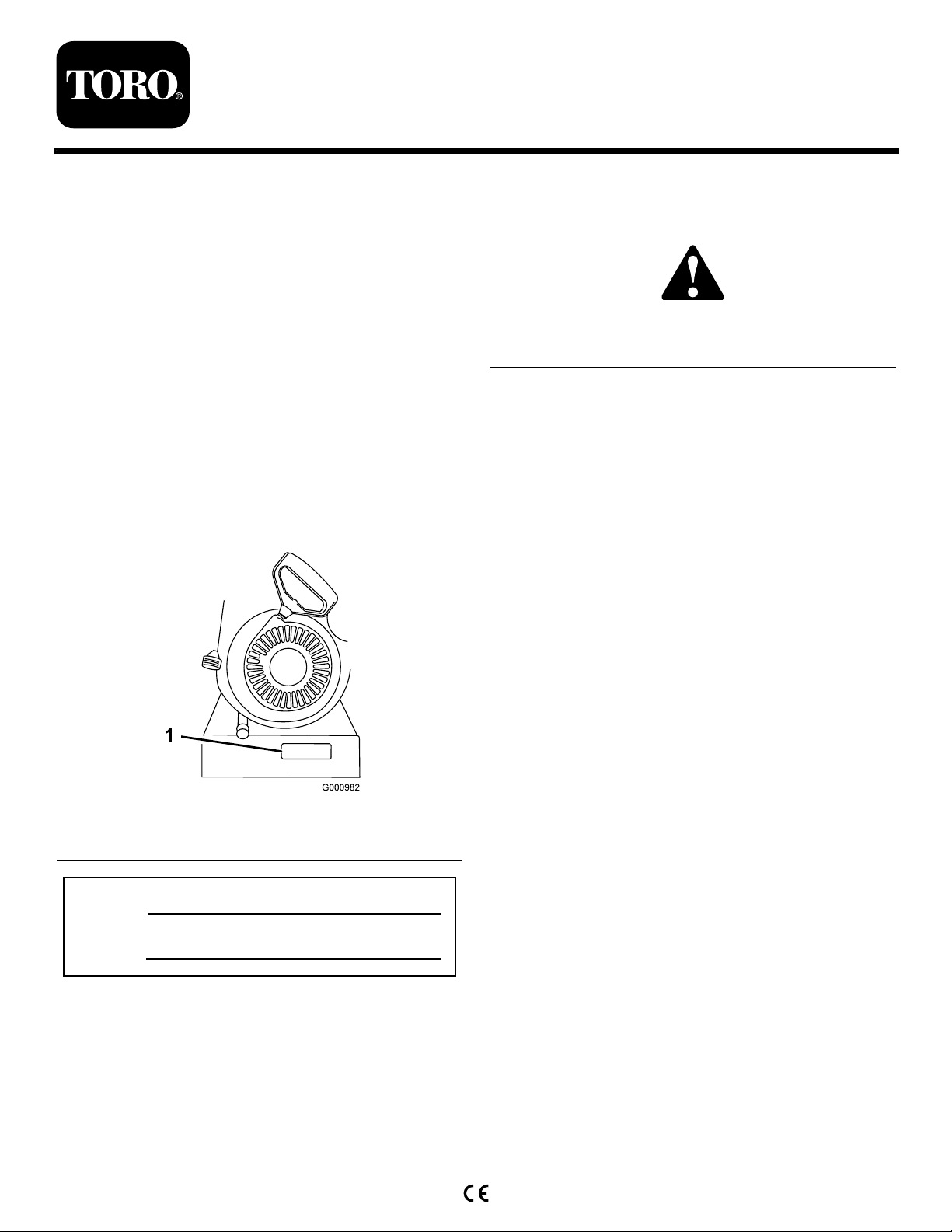
Figure1identiesthelocationofthemodelandserial
numbersontheproduct.Writethenumbersinthe
spaceprovided.
injuryordeathifyoudonotfollowtherecommended
precautions.
Figure2
1.Safetyalertsymbol
Thismanualuses2wordstohighlightinformation.
Importantcallsattentiontospecialmechanical
informationandNoteemphasizesgeneralinformation
worthyofspecialattention.
ReplacementEngineOwner’sManualsmaybe
orderedthroughtheenginemanufacturer.
Figure1
1.Modelandserialnumberlocation
ModelNo.
SerialNo.
Thismanualidentiespotentialhazardsandhas
safetymessagesidentiedbythesafetyalertsymbol
(Figure2),whichsignalsahazardthatmaycauseserious
©2007—TheT oro®Company
8111LyndaleAvenueSouth
Bloomington,MN55420
Registeratwww.Toro.com.
OriginalInstructions(EN)
PrintedintheUSA
AllRightsReserved
Page 2
Safety
BeforeOperating
?
?
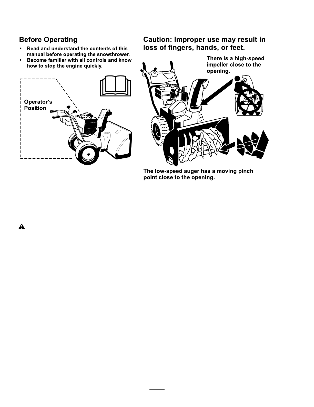
Readandunderstandthecontentsofthis
manualbeforeoperatingthesnowthrower .
Becomefamiliarwithallcontrolsandknow
howtostoptheenginequickly .
Operator 's
Position
Thelow-speedaugerhasamovingpinch
pointclosetotheopening.
Caution:Improperusemayresultin
lossoffingers,hands,orfeet.
Thereisahigh-speed
impellerclosetothe
opening.
ThissnowthrowermeetsorexceedstheISO
standard8437ineffectatthetimeofproduction.
Readandunderstandthecontentsofthismanual
beforetheengineiseverstarted.
Thisisthesafetyalertsymbol.Itisusedtoalert
youtopotentialpersonalinjuryhazards.Obeyall
safetymessagesthatfollowthissymboltoavoid
possibleinjuryordeath.
Improperlyusingormaintainingthissnowthrower
couldresultininjuryordeath.Toreducethis
potential,complywiththefollowingsafety
instructions.
Training
•Readtheoperatingandserviceinstructionmanual
carefully.Bethoroughlyfamiliarwiththecontrols
andtheproperuseoftheequipment.Knowhowto
stoptheunitanddisengagethecontrolsquickly.
•Neverallowchildrentooperatetheequipment.
Neverallowadultstooperatetheequipmentwithout
properinstruction.
•Keeptheareaofoperationclearofallpersons,
particularlysmallchildren,andpets.
•Exercisecautiontoavoidslippingorfalling,
especiallywhenoperatinginreverse.
Preparation
•Thoroughlyinspecttheareawheretheequipmentis
tobeusedandremovealldoormats,sleds,boards,
wires,andotherforeignobjects.
•Disengageallclutchesandshiftintoneutralbefore
startingtheengine.
•Donotoperatetheequipmentwithoutwearing
adequatewintergarments.Wearfootwearwhichwill
improvefootingonslipperysurfaces.
•Handlefuelwithcare;itishighlyammable.
–Useanapprovedfuelcontainer.
–Neveraddfueltoarunningorhotengine.
–Fillfueltankoutdoorswithextremecare.Never
–Replacegasolinecapssecurelyandwipeup
•Adjustthecollectorhousingheighttocleargravel
orcrushedrocksurface.
•Neverattempttomakeanyadjustmentswhile
theengineisrunning(exceptwherespecically
recommendedbymanufacturer).
•Letengineandmachineadjusttooutdoor
temperaturesbeforestartingtoclearsnow.
•Theoperationofanypoweredmachinecanresultin
foreignobjectsbeingthrownintotheeyes.Always
llfueltankindoors.
spilledfuel.
2
Page 3

wearsafetyglassesoreyeshieldsduringoperationor
whileperforminganadjustmentorrepair.
•Useonlyattachmentsandaccessoriesapprovedby
themanufacturerofsnowthrower(suchaswheel
weights,counterweights,cabs,etc.).
Operation
•Donotputhandsorfeetnearorunderrotatingparts.
Keepclearofthedischargeopeningatalltimes.
•Exerciseextremecautionwhenoperatingonor
crossinggraveldrives,walks,orroads.Stayalertfor
hiddenhazardsortrafc.
•Afterstrikingaforeignobject,stoptheengine,
removethewirefromthespark-plug,thoroughly
inspectthesnowthrowerforanydamage,andrepair
thedamagebeforerestartingandoperatingthesnow
thrower.
•Iftheunitshouldstarttovibrateabnormally,stop
theengineandcheckimmediatelyforthecause.
Vibrationisgenerallyawarningoftrouble.
•Stoptheenginewheneveryouleavetheoperating
position,beforeuncloggingthecollector/impeller
housingordischargeguide,andwhenmakingany
repairs,adjustments,orinspections.
•Whencleaning,repairing,orinspecting,makecertain
thecollector/impellerandallmovingpartshave
stopped.Disconnectthespark-plugwire,andkeep
thewireawayfromtheplugtopreventaccidental
starting.
•Donotruntheengineindoors,exceptwhenstarting
itandformovingthesnowthrowerinoroutofthe
building.Opentheoutsidedoors;exhaustfumes
aredangerous.
•Donotclearsnowacrossthefaceofslopes.Exercise
extremecautionwhenchangingdirectiononslopes.
Donotattempttoclearsteepslopes.
•Neveroperatethesnowthrowerwithoutproper
guards,plates,orothersafetyprotectivedevicesin
place.
•Neveroperatethesnowthrowernearglass
enclosures,automobiles,windowwells,drop-offs,
etc.withoutproperadjustmentofthesnow
dischargeangle.Keepchildrenandpetsaway .
•Donotoverloadthemachinecapacitybyattempting
toclearsnowattoofastarate.
•Neveroperatethemachineathightransportspeeds
onslipperysurfaces.Usecarewhenreversing.
•Neverdirectdischargeatbystandersorallowanyone
infrontoftheunit.
•Disengagepowertothecollector/impellerwhen
snowthroweristransportedornotinuse.
•Neveroperatethesnowthrowerwithoutgood
visibilityorlight.Alwaysbesureofyourfooting,and
keeparmholdonthehandles.Walk;neverrun.
•Neveroperatethesnowthrowerwithoutgood
visibilityorlight.
•Takeallpossibleprecautionswhenleavingthe
machineunattended.Shiftintoneutral,setthe
parkingbrake,stoptheengineandremovethekey.
MaintenanceandStorage
•Checkallfastenersatfrequentintervalsforproper
tightnesstobesuretheequipmentisinsafeworking
condition.
•Neverstorethemachinewithfuelinthefueltank
insideabuildingwhereignitionsourcesarepresent
suchashotwaterandspaceheaters,clothesdryers,
etc.Allowtheenginetocoolbeforestoringinany
enclosure.
•Alwaysrefertoowner’sguideinstructionsfor
importantdetailsifthesnowthroweristobestored
foranextendedperiod.
•Maintainorreplacesafetyandinstructionslabels,
asnecessary.
•Runthemachineafewminutesafterthrowingsnow
topreventfreeze-upofthecollector/impeller.
ToroSnowthrowerSafety
Thefollowinglistcontainssafetyinformationspecic
toToroproductsorothersafetyinformationthatyou
mustknow.
•Rotatingrotorbladescaninjurengersor
hands.Staybehindthehandlesandawayfromthe
dischargeopeningwhileoperatingthesnowthrower.
Keepyourface,hands,feet,andanyotherpart
ofyourbodyorclothingawayfrommovingor
rotatingparts.
•Beforeadjusting,cleaning,repairing,andinspecting
thesnowthrower,andbeforeuncloggingthe
dischargechute,stoptheengine,removethekey,
andwaitforallmovingpartstostop.
•Usethesnowcleanouttool,notyourhands,to
removeobstructionsfromthedischargechute.
•Beforeleavingtheoperatingposition,stopthe
engine,removethekey,andwaitforallmovingparts
tostop.
3
Page 4
•Donotwearloose-ttingclothingthatcouldget
caughtinmovingparts.
container.Removethekeyfromtheignitionswitch
beforestoringthesnowthrower.
•Ifashield,safetydevice,ordecalisdamaged,
illegible,orlost,repairorreplaceitbeforebeginning
operation.Also,tightenanyloosefasteners.
•Donotsmokewhilehandlinggasoline.
•Donotusethesnowthroweronaroof.
•Donottouchtheenginewhileitisrunningorsoon
afterithasstoppedbecausetheenginemaybehot
enoughtocauseaburn.
•Performonlythosemaintenanceinstructions
describedinthismanual.Beforeperformingany
maintenance,service,oradjustment,stoptheengine,
removethekey,anddisconnectthewirefromthe
sparkplug.Ifmajorrepairsareeverneeded,contact
anAuthorizedServiceDealer.
•Donotchangethegovernorsettingsontheengine.
•Whenstoringthesnowthrowerformorethan30
days,drainthefuelfromthefueltanktoprevent
apotentialhazard.Storefuelinanapprovedfuel
•PurchaseonlygenuineTororeplacementpartsand
accessories.
SoundPressure
Thisunithasamaximumsoundpressurelevelatthe
operator’searof93dBA,basedonmeasurementsof
identicalmachinesperEN11201.
SoundPower
Thisunithasaguaranteedsoundpowerlevelof108
dBA,basedonmeasurementsofidenticalmachinesper
EN3744.
Vibration
Thisunitdoesnotexceedahand/armvibrationlevelof
4.6m/s
perEN1033.
2
,basedonmeasurementsofidenticalmachines
SafetyandInstructionalDecals
Important:Safetyandinstructiondecalsarelocatednearareasofpotentialdanger.Replacedamaged
decals.
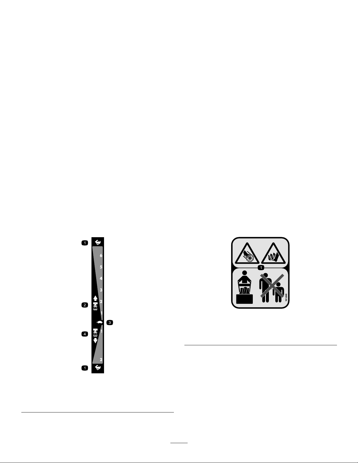
107-3040
1.Cuttingdismemberment,impellerandcutting
dismemberment,augerhazards—keepbystandersasafe
distancefromthesnowthrower.
106-4525
Reorderpartno.1 12-6633
1.Fast
2.Forwardspeeds4.Reversespeeds
3.Slow
4
Page 5
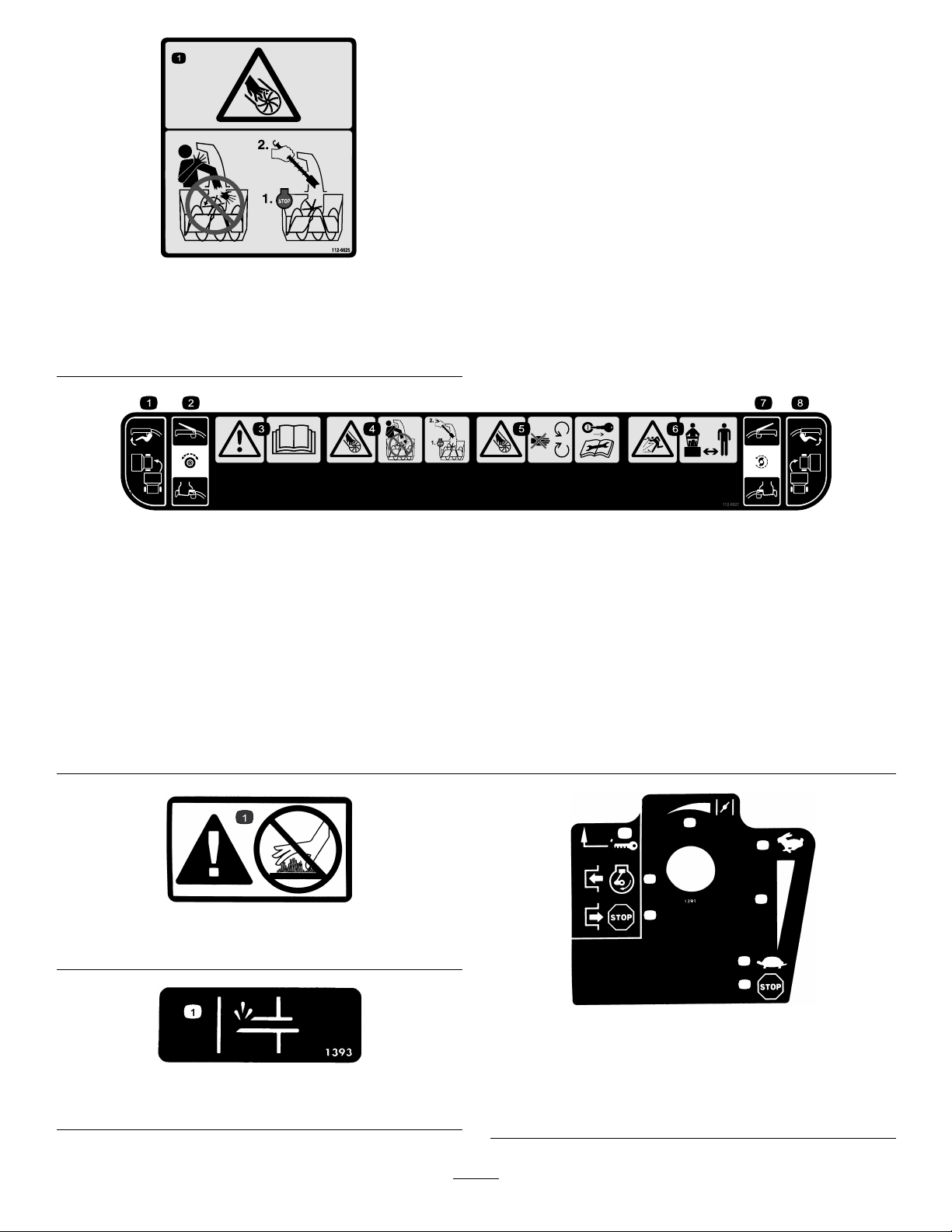
112-6625
1
2
3
4
5
6
5
7
Reorderpartno.1 12-6629
1.Cutting/dismembermenthazard,impeller—donotplace
yourhandinthechute;stoptheenginebeforeleavingthe
operator’sposition,usethetooltoclearthechute.
1.Leftturncontrol
2.Tractiondrive—squeeze
thelevertoengage;release
thelevertodisengage.
3.Warning—readthe
Operator’sManual.
4.Cutting/dismemberment
hazard,impeller—do
notplaceyourhand
inthechute;stopthe
enginebeforeleavingthe
operator’sposition,usethe
tooltoclearthechute.
112-6627
5.Cutting/dismemberment
hazard,impeller—keep
awayfrommovingparts;
removetheignitionkeyand
readtheinstructionsbefore
servicingorperforming
maintenance.
6.Thrownobject
hazard—keepbystanders
asafedistancefromthe
snowthrower.
7.Auger/impeller
drive—squeezetheleverto
engage;releasethelever
todisengage.
8.Rightturncontrol
TecumsehPartNo.37119
1.Warning—hotsurface,donottouch
1.Primer
TecumsehPartNo.36501
TecumsehPartNo.35077
1.Keyignition5.Increasingscale
2.Engagetostarttheengine
3.Disengagetostopthe
engine
4.Fast
5
6.Slow
7.Stoptheengine
Page 6

Setup
LooseParts
Usethechartbelowtoverifythatallpartshavebeenshipped.
ProcedureDescription
1.
2.
3.
4.
5.
6.
7.
8.
9.
Handlebolts4
Curvedwashers
Locknuts4
Nopartsrequired
Nopartsrequired
Carriagebolts
Locknuts2
Cabletie
Nopartsrequired
Nopartsrequired
Nopartsrequired
Nopartsrequired
Qty.
Use
4
–
–
2
1
–
–
–
–
Installtheupperhandle.
Installthewheelclutchcableends
Installthetractioncontrollinkage.
Installthechutecontrolrod.
Connectthewiretotheheadlight.
Filltheenginewithoil.
Checkthetirepressure.
Checktheskids.
Checktheoperationofthetractiondrive.
6
Page 7
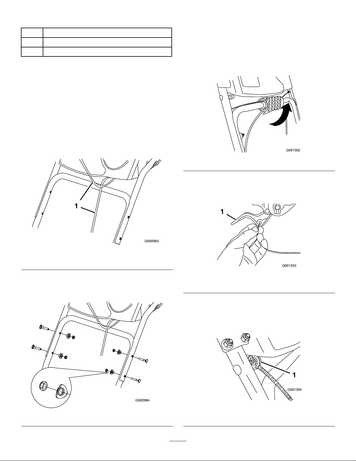
1.InstallingtheUpperHandle
2.InstallingtheWheelClutch
4Handlebolts
4
Curvedwashers
4Locknuts
Procedure
Note:Donotremovetherubberbandonthecables
untilyouhaveinstalledtheupperhandle.
1.Liftandrotatetheupperhandleandpositionitover
thelowerhandle(Figure3).
Important:Routethecablesattachedtothe
QuickStickinsidetheupperhandlelegsand
ensurethatthecablesandthewireforthe
headlightarenotpinchedbetweenthehandle
sections.
CableEnds
Procedure
1.Unwrapthecableendsfromthelowerhandle
(Figure5).
Figure5
2.Routeeithertheleftorrightcableendoverthelower
handleandinsertthecableendintotheholeinthe
correspondingwheelclutchlever(Figure6).
Figure3
1.Cables
2.Securetheupperhandlewith4handlebolts,
4curvedwashers,and4locknutsfromtheloose
partsbag(Figure4).
Figure4
Figure6
1.Wheelclutchlever
3.Removethenutandwasherfromthehandle,attach
thecableclamponthecabletothehandle,install
thewasherandthenut,andhandtightenthenut
(Figure7).
Figure7
1.Cableclamp(2)
7
Page 8
Important:Ensurethatthecurvedsideofthe
cableclampisagainstthehandleandthatthe
cableisroutedbelowtheclampbolt.Thecable
mustbeinastraightlinefromthecableclamp
tothepointwhereitattachestothewheelclutch
lever.
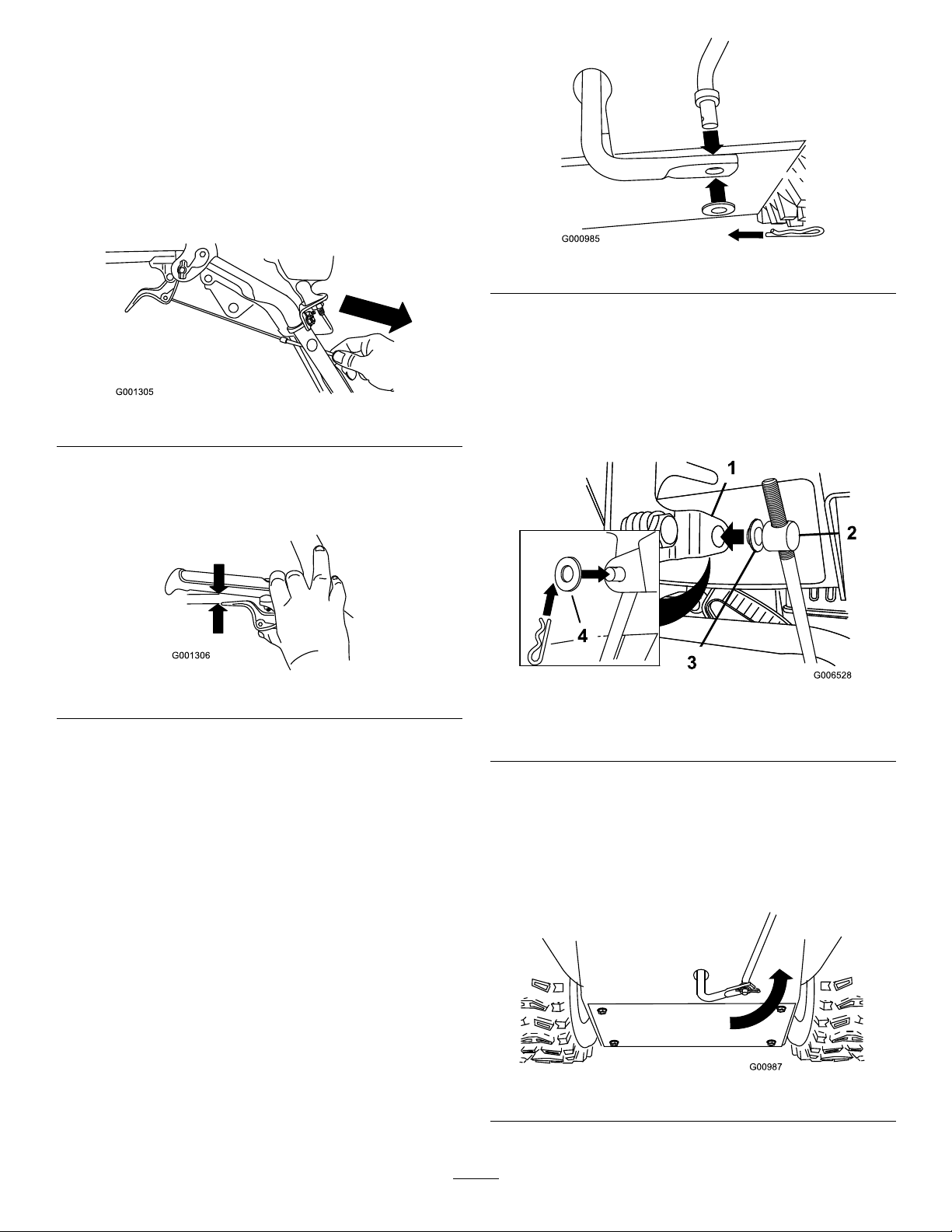
4.Pullthecablejacketdowngentlyuntilthewheel
clutchleverisdownandtheslackisoutofthecable,
thentightenthecableclampnutsecurely(
Figure8
Figure8).
5.Squeezetheleverfully,thencheckthegapbetween
thebottomofthehandleandthewheelclutchlever
Figure9).
end(
Figure10
2.Securethelowerendofthespeedcontrolrodwith
thewasherandhairpincotterthatyoupreviously
removed.
3.Removethehairpincotterandtheouterwasher
fromthetrunnionontheupperendofthespeed
controlrod(Figure11).
Figure9
Note:Thegapshouldbeapproximatelythe
thicknessofapencil(1/4inchor6mm).Ifitis
greater,loosenthecableclampnut,slidethecable
jacketupslightly,tightenthecableclampnut,and
checkthegapagain.
6.Repeatsteps2through5fortheothercable.
3.InstallingtheTraction
ControlLinkage
Procedure
1.Removethehairpincotterandwasherfromthe
lowerendofthespeedcontrolrodandinsertthe
lowerendoftherodintothelowerlinkarmsothat
thebentendofthespeedcontrolrodfacesrearward
(Figure10).
Figure11
1.Speedselectorlever
2.Trunnion
3.Innerwasher
4.Outerwasher
Note:Tomakeinstallationeasier,leavetheat
washeronthetrunnion(Figure11).
4.ShiftthespeedselectorleverintoPositionR2.
5.Rotatethelowerlinkarmfullyupward
(counterclockwise)(
Figure12).
Figure12
8
Page 9
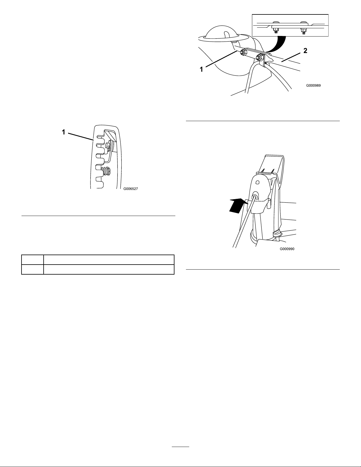
6.Liftuponthespeedcontrolrodandinsertthe
trunnionintotheholeinthespeedselectorlever
(Figure11).
Note:Ifthetrunniondoesnottintothehole
whenyouliftuponthespeedcontrolrod,rotatethe
trunnionupwardordownwardonthespeedcontrol
roduntilitts.
7.Securethetrunnionandupperendofthespeed
controlrodwiththeouterwasherandahairpin
cotteryoupreviouslyremoved.
Note:Foreasierinstallation,lookdownthrough
theopeninginthespeedselector(Figure13).
Figure14
1.Shortrod
2.Longchutecontrolrod
4.Insertthefrontendoftherodintotheopeningin
thebackofthechutegearcoveruntilitslidesinto
thechutegear(Figure15).
Figure13
1.Speedselector
4.InstallingtheChuteControl
Rod
2
Carriagebolts
2Locknuts
Procedure
1.UnwraptheQuickStickandrotateitsothatitis
uprightandinthecenter.
2.Holdthebluetriggercapdownandpullthelever
fullyrearward.
Note:Thedischargechuteanddeectorshould
faceforward.Iftheydonot,holdthebluetrigger
capdown(butdonotmovetheQuickStick)and
rotatethedischargechuteuntiltheydo.
Figure15
5.Aligntheholesinthenestedendsoftherodsand
insert2carriagebolts(intheloosepartsbag)through
theshortrodfromtheleftsideofthesnowthrower
(fromtheoperatingposition).
6.Insertthecableclipthatsupportsthedeector
cableontotheforwardcarriagebolt,andsecurethe
carriageboltswithlocknutsfromtheloosepartsbag
(Figure16).
3.Aligntheattenedbackendofthelongchute
controlrodwiththeattenedfrontendoftheshort
rodthatextendsfromthecontrolpanelsothatthey
nesttogether(Figure14).
9
Page 10
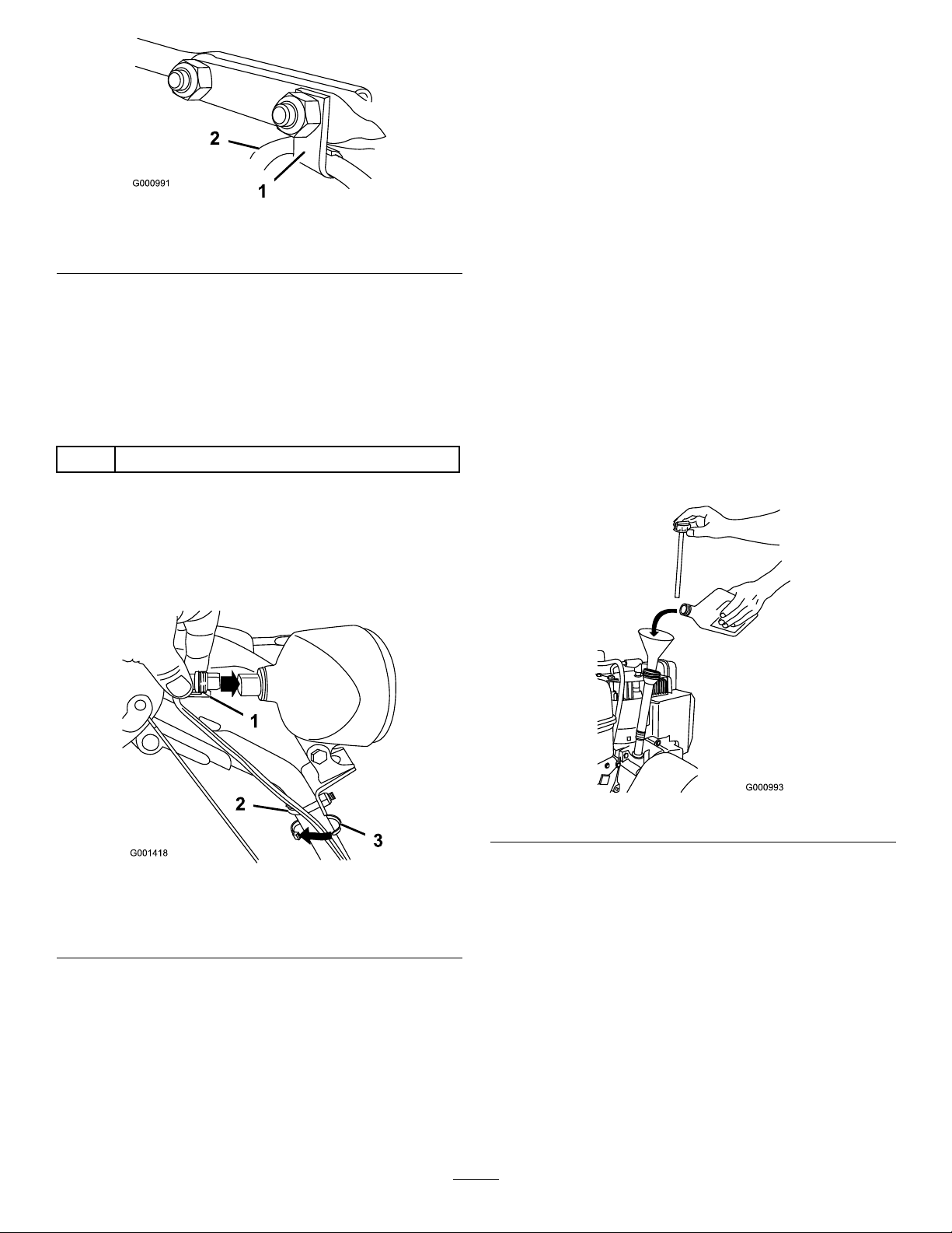
Figure16
1.Cableclip2.Deectorcable
7.HoldthebluetriggercapdownandrotatetheQuick
Stickinacircletoensurethatthechuteanddeector
operatesmoothly.
6.FillingtheEnginewithOil
Procedure
Yoursnowthrowercomeswith26oz.ofoilinthe
engine.
Note:Beforestartingtheengine,checktheoillevel
andaddoilifnecessary.
Max.ll:26oz.(0.77l),type:automotivedetergent
oilwithanAPIserviceclassicationofSF,SG,SH,SJ,
SL,orhigher.
•Fortemperaturesabove32°F(0°C),useSAE30W .
•Fortemperaturesbetween0°Fand32°F(-18°Cto
0°C),useSAE5W30orSAE10W .
5.ConnectingtheWiretothe
Headlight
1
Cabletie
Procedure
1.Insertthewireconnectoronthelooseendofthe
wirestraightintothebackoftheheadlightuntilitis
securelyinplace(Figure17).
•Forairtemperaturesbelow0°F(-18°C),use
SAE0W30.
1.Removethedipstickandslowlypouroilintotheoil
lltubetoraisetheoilleveltotheFullmarkonthe
dipstick.Donotoverll.(
Figure18
Figure18).
Figure17
1.Plasticcliponwire
connector
2.U-bolt
Note:Ensurethattheplasticcliponthewire
connectorisonthebottom(Figure17).
2.Secureacabletie(fromtheloosepartsbag)around
thewireandthehandleaboutaninch(2.5cm)below
theU-bolt(Figure17).
3.Cabletie
2.Installthedipsticksecurely.
Note:Donotspilloilaroundtheoillltube;oil
couldleakontotractionpartsandcausethetraction
toslip.
7.CheckingtheTirePressure
Procedure
Thetiresareoverinatedatthefactoryforshipping.
Reducethepressureequallyinbothtirestobetween17
and20psi(116and137kPa).
10
Page 11
8.CheckingtheSkids
5.MovethespeedselectortothePosition1;referto
OperatingtheSpeedSelector.
Procedure
RefertoCheckingandAdjustingtheSkidsin
Maintenance.
9.CheckingtheTractionDrive
Operation
Procedure
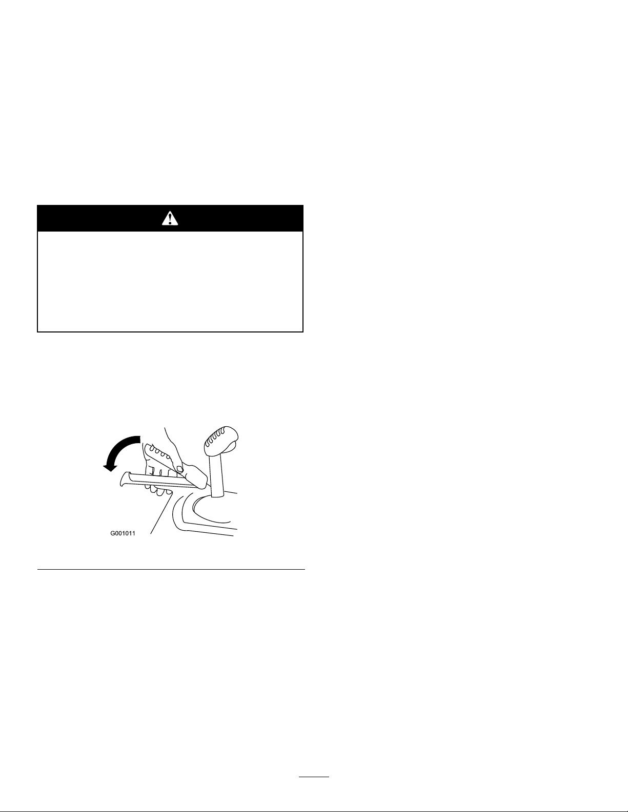
Ifthetractiondriveisnotproperlyadjusted,
thesnowthrowermaymoveinthedirection
oppositeofwhatyouintended,causinginjury
and/orpropertydamage.
Carefullycheckthetractiondriveandadjustit
properly,ifnecessary.
1.Starttheengine;refertoStartingtheEngine.
2.MovethespeedselectortoPositionR1;referto
OperatingtheSpeedSelector.
6.Squeezethelefthand(traction)levertothehand-grip
(
Figure19).
Thesnowthrowershouldmoveforward.Ifthe
snowthrowerdoesnotmoveormovesrearward,
completethefollowing:
A.Releasethetractionleverandstoptheengine.
B.Disconnectthetrunnionfromthespeedselector
lever(Figure11).
C.Turnthetrunnionupward(counterclockwise)on
thespeedcontrolrod(Figure11).
D.Connectthetrunniontothespeedselectorlever
(Figure11).
7.Ifyoumadeanyadjustments,repeatthisprocedure
untilnoadjustmentsarerequired.
Important:Ifthesnowthrowermoveswhenthe
tractionleverisinthereleasedposition,checkthe
tractioncable(refertoCheckingandAdjusting
theTractionCable)ortakethesnowthrowertoan
AuthorizedServiceDealerforservice.
3.Squeezethelefthand(traction)levertothehand-grip
(Figure19).
Figure19
Thesnowthrowershouldmoverearward.Ifthe
snowthrowerdoesnotmoveormovesforward,
completethefollowing:
A.Releasethetractionleverandstoptheengine.
B.Disconnectthetrunnionfromthespeedselector
lever(Figure11).
C.Turnthetrunniondownward(clockwise)onthe
speedcontrolrod(Figure11).
D.Connectthetrunniontothespeedselectorlever
(Figure11).
4.Releasethetractionlever.
11
Page 12
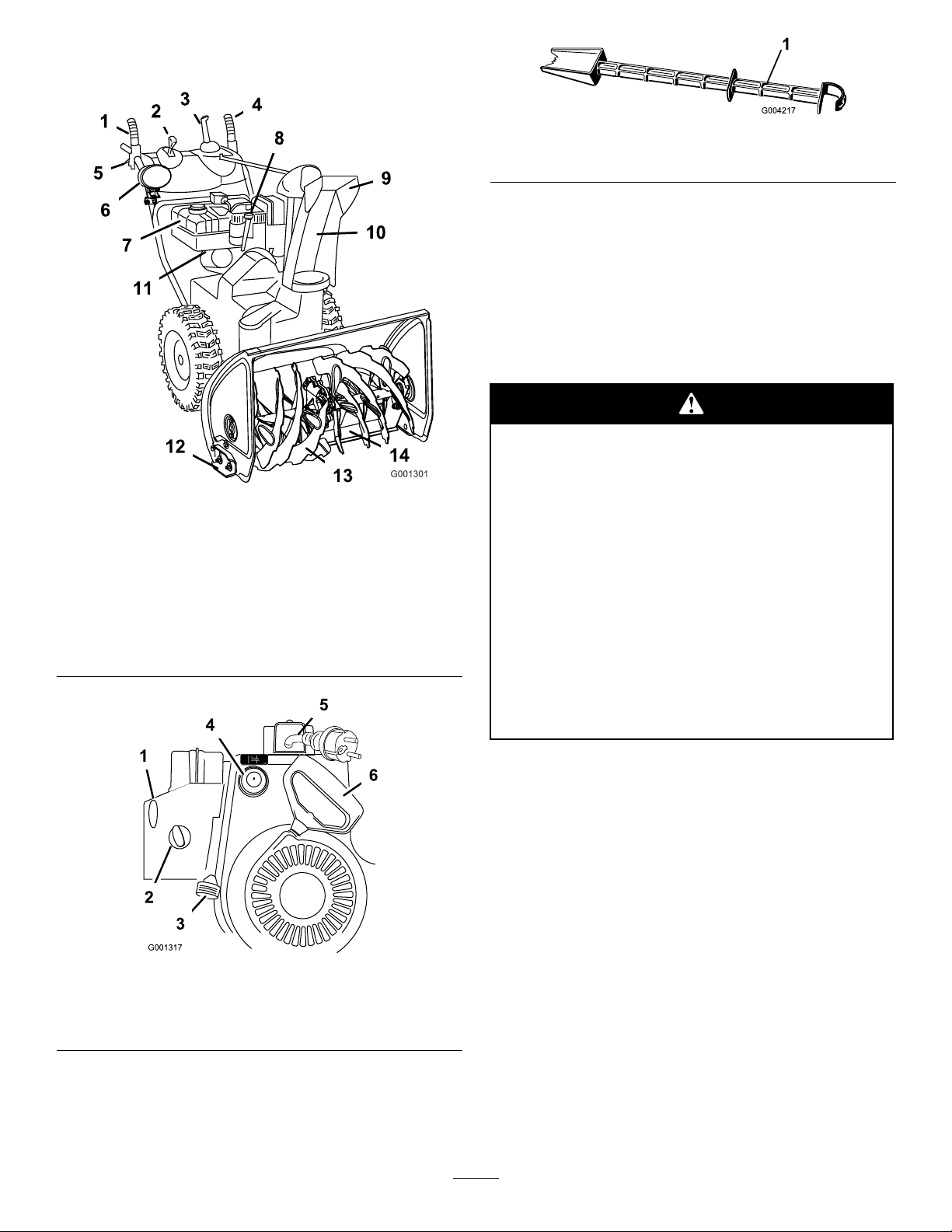
ProductOverview
Figure20
1.Auger/impellerlever8.Engineoillltube/dipstick
2.Speedselectorlever9.Chutedeector
3.QuickStickdischarge
chutecontrol
4.Tractionlever
5.Wheelclutchlever(2)12.Skid(2)
6.Headlight13.Auger
7.Fueltank
10.Dischargechute
11.Fuelshutoffvalve
14.Scraper
Figure22
1.Snowcleanouttool(attachedtothehandle)
Operation
Note:Determinetheleftandrightsidesofthemachine
fromthenormaloperatingposition.
FillingtheFuelTank
Gasolineisextremelyammableandexplosive.
Areorexplosionfromgasolinecanburnyou
andothers.
•Topreventastaticchargefromigniting
thegasoline,placethecontainerand/or
snowthroweronthegroundbeforelling,
notinavehicleoronanobject.
•Fillthetankoutdoorswhentheengineis
cold.Wipeupspills.
•Donothandlegasolinewhensmokingor
aroundanopenameorsparks.
Figure21
1.Ignitionswitch4.Primer
2.Choke
3.Throttle6.Recoilstarter
5.Electricstarter
•Storegasolineinanapprovedfuelcontainer,
outofthereachofchildren.
Fillthefueltankwithfreshunleadedregulargasoline
fromamajorname-brandservicestation(Figure23).
Important:T oreducestartingproblems,add
fuelstabilizertothefuelallseason,mixingitwith
gasolinelessthan30daysold.
Do not add oil to
the gasoline.
12
Page 13
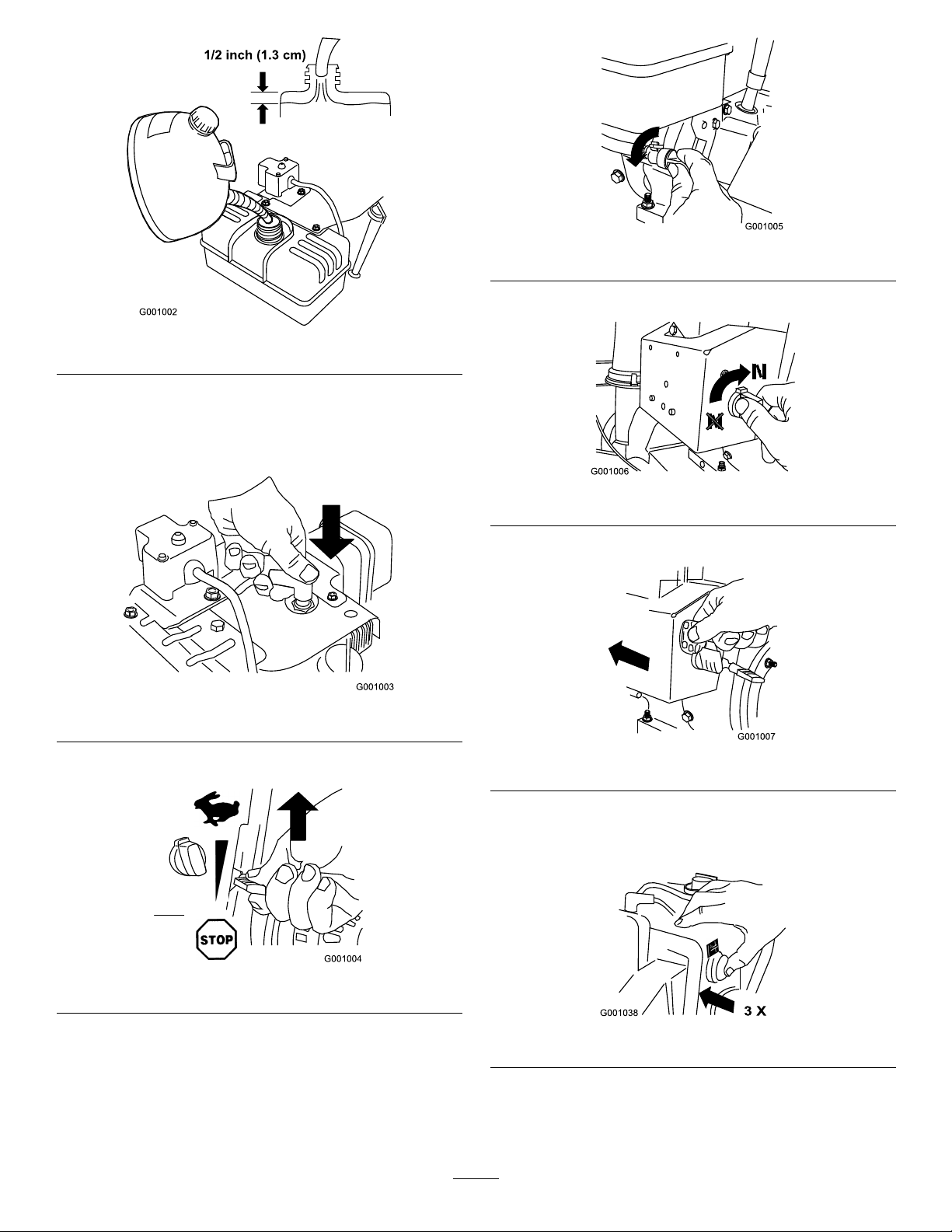
Figure23
StartingtheEngine
1.Connectthesparkplugwire(Figure24).
Figure26
4.RotatethechoketotheOnposition(Figure27).
Figure27
5.Inserttheignitionkey(Figure28).
Figure24
2.MovethethrottletotheFastposition(Figure25).
Figure25
3.Rotatethefuelshutoffvalvecounterclockwiseto
openit(Figure26).
Figure28
6.Firmlypushintheprimer3timeswithyourthumb,
holdingtheprimerinforasecondbeforereleasing
iteachtime(Figure29).
Figure29
Note:Takeyourgloveoffwhenyoupushinthe
primersothataircannotescapefromtheprimer
hole.
13
Page 14
Note:Primingexcessivelymayoodtheengineand
preventitfromstarting.
7.Startthesnowthrowerusingtherecoilstarterorthe
electricstarter(Figure21).
Important:Topreventdamagingtheelectric
starter,runitnomorethan10timesatintervals
of5secondson,then5secondsoff.Iftheengine
doesnotstartafterthisseriesofattempts,allow
thestartertocoolforatleast40minutesbefore
tryingtostartitagain.Iftheenginestilldoes
notstart,takethesnowthrowertoanAuthorized
ServiceDealerforservice.
8.Disconnectthecordfromtheelectricstarterand
theoutlet.
Figure31
4.Pulltherecoilstarter3or4times.Thishelpsprevent
therecoilstarterfromfreezingup.
9.Whentheenginestarts,setthechoketothe
3/4position.Astheenginewarmsup,setthechoke
tothe1/2position.Whentheengineiswarm,set
thechoketotheOffposition.
Ifyouleavethesnowthrowerpluggedintoa
poweroutlet,someonecaninadvertentlystart
thesnowthrowerandinjurepeopleordamage
property.
Unplugthepowercordwheneveryouarenot
startingthesnowthrower.
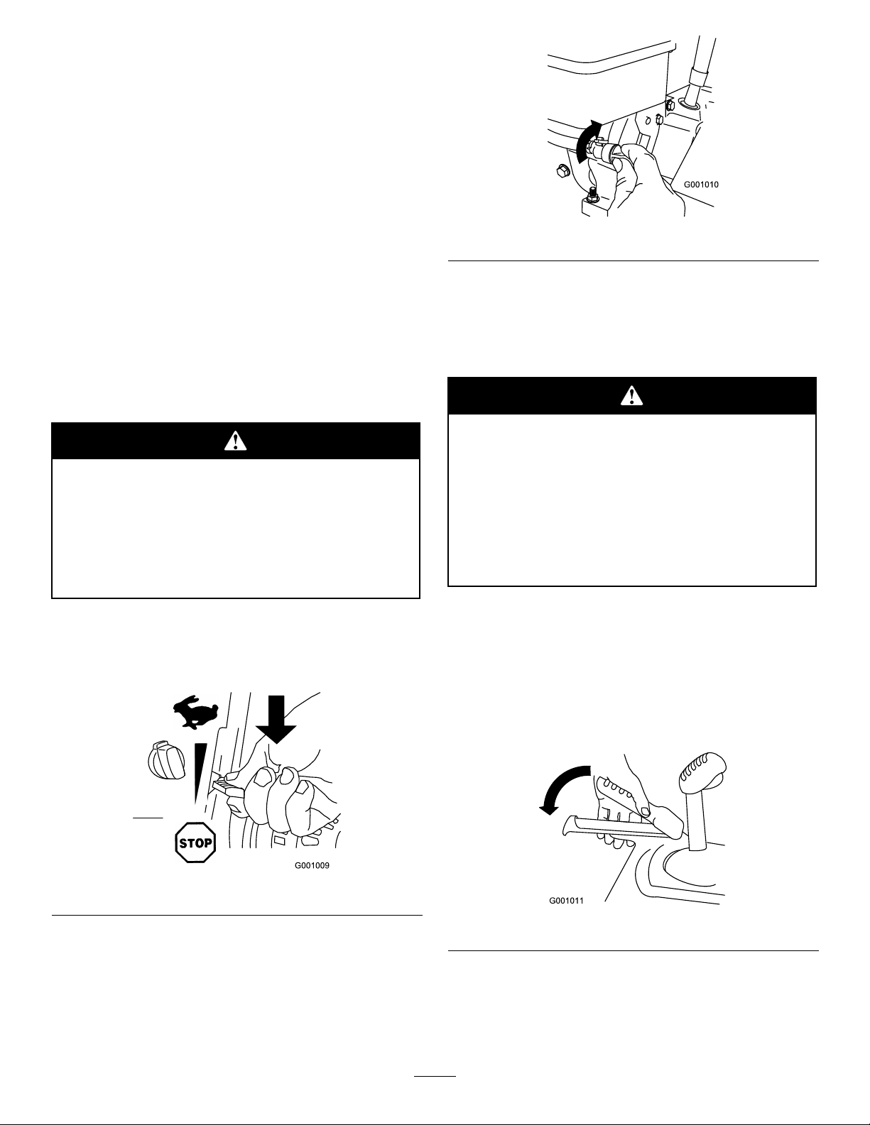
StoppingtheEngine
1.MovethethrottletotheStopposition(Figure30).
OperatingtheTractionDrive
Ifthetractiondriveisnotproperlyadjusted,
thesnowthrowermaymoveinthedirection
oppositeofwhatyouintended,causinginjury
and/orpropertydamage.
Carefullycheckthetractiondriveandadjust
itproperly,ifnecessary;refertoCheckingthe
TractionDriveOperationinSetupformore
information.
Important:Ifthesnowthrowermoveswhenthe
tractionleverisinthereleasedposition,checkthe
tractioncable(refertoCheckingandAdjusting
theTractionCable)ortakethesnowthrowertoan
AuthorizedServiceDealerforservice.
1.Toengagethetractiondrive,squeezethelefthand
(traction)levertothehand-grip(Figure32).
Figure30
2.Waitforallmovingpartstostopbeforeleavingthe
operatingposition.
3.Closethefuelshutoffvalvebyrotatingitclockwise
(Figure31).
Figure32
2.Tostopthetractiondrive,releasethetractionlever.
14
Page 15
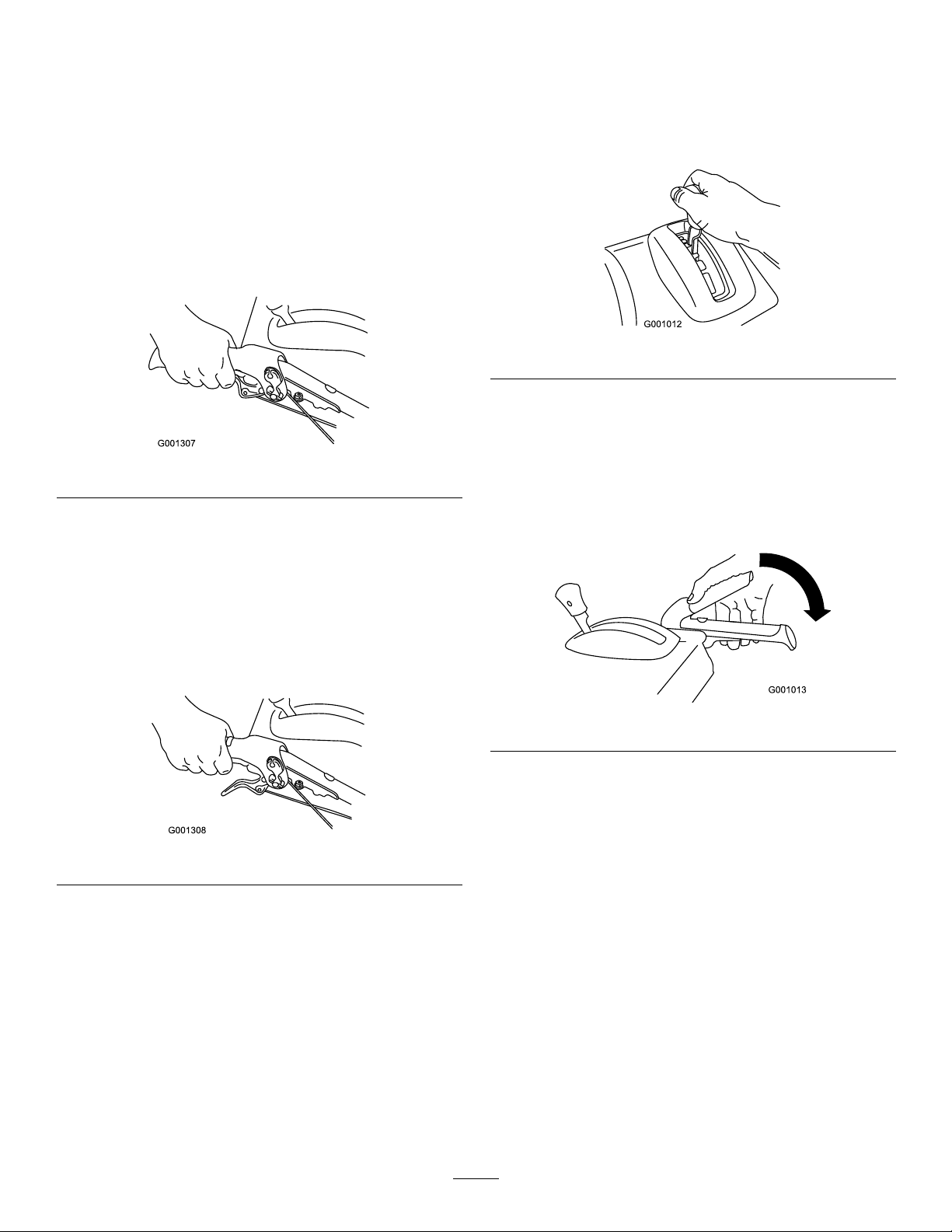
UsingtheWheelClutchLevers
OperatingtheSpeedSelector
Thewheelclutchleversallowyoutomomentarily
disengagethedrivetooneorbothwheelswiththe
tractiondriveleverstillengaged.Thisenablesyouto
turnandmaneuverthesnowthrowereasily.
Note:Holdingdownthetractionleveragainstthe
handleengagesthetractiondrivetobothwheels.
Toturnthesnowthrowertotheright,liftuponthe
rightwheelclutchleverandsqueezeittowardthehandle
(Figure33).
Figure33
Note:Thisdisengagesthedrivetotherightwheelwhile
theleftwheelcontinuesdriving,andthesnowthrower
turnstotheright.
Thespeedselectorhas6forwardand2reversegears.
Tochangespeeds,releasethetractionleverandshiftthe
speedselectorlevertothedesiredposition(Figure35).
Theleverlocksinanotchateachspeedselection.
Figure35
OperatingtheAuger/Impeller
Drive
1.Toengagetheauger/impellerdrive,squeezethe
righthand(auger/impeller)levertothehandgrip
Figure36).
(
Note:Similarly,squeezingtheleftwheelclutchlever
turnsthesnowthrowertotheleft.
Whenyoucompletetheturn,releasethewheelclutch
lever,andthedrivere-engagesbothwheels(Figure34).
Figure34
Momentarilysqueezingandreleasingtheleftorright
wheelclutchleveralsoallowsforsteeringadjustmentsto
keepthesnowthrowergoinginastraightline,especially
indeepsnow .
Squeezingbothwheelclutchleverssimultaneously
disengagesthedrivetobothwheels.Thisenablesyou
tomanuallymovethesnowthrowerbackwardwithout
stoppingtoshiftitintoareversegear.Italsoallowsyou
tomaneuverandtransportthesnowthrowermoreeasily
whentheengineisnotrunning.
Figure36
2.Tostoptheaugerandimpeller,releasetheright
handlever.
Important:Whenyouengageboththe
auger/impellerleverandthetractionlever,the
tractionleverlockstheauger/impellerlever
down,freeingyourrighthand.T oreleaseboth
levers,simplyreleasethelefthand(traction)
lever.
3.Iftheaugerandimpellercontinuetorotatewhen
youreleasetheauger/impellerlever,donotoperate
thesnowthrower.Checktheauger/impellercable
(refertoCheckingandAdjustingtheAuger/Impeller
Cable)andadjustitifnecessary.Otherwise,takethe
snowthrowertoanAuthorizedDealerforservice.
15
Page 16
•Ifthechutedoesnotmove,refertoAdjustingthe
DischargeChuteLatch.
Iftheaugerandimpellercontinuetorotate
whenyoureleasetheauger/impellerlever,you
couldseriouslyinjureyourselforothers.
Donotoperatethesnowthrower.Takeittoan
AuthorizedServiceDealerforservice.
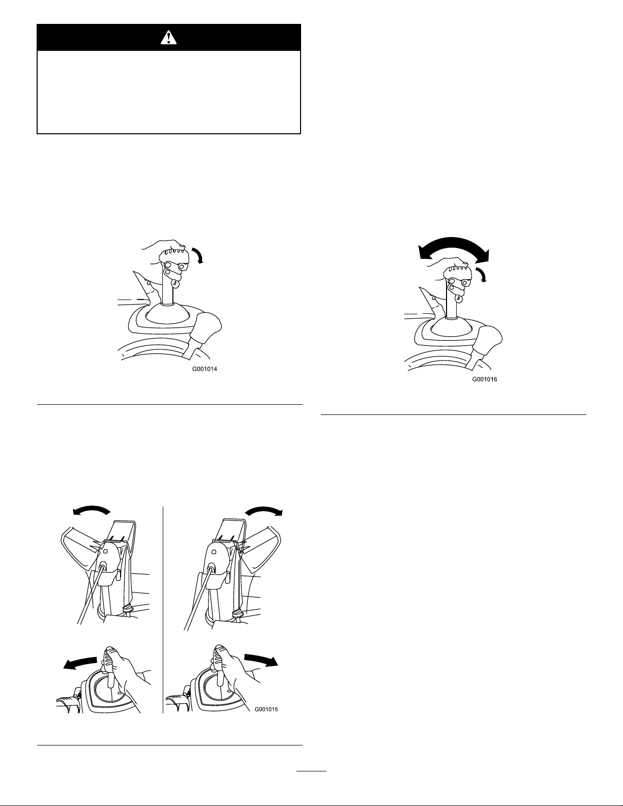
OperatingtheQuickStick
HoldthebluetriggercapdowntousetheQuickStick
tomovethedischargechuteandthechutedeector.
Releasethetriggercaptolockthedischargechuteand
chutedeectorintoposition(Figure37).
®
•Ifthechutedoesnotturnasfartotheleftasitdoes
totheright,ensurethatthecableisroutedtothe
insideofthehandles.RefertoInstallingtheUpper
Handle.
•Ifthechutedoesnotlockintoplacewhenyourelease
thetriggercap,refertoAdjustingtheDischarge
ChuteLatch.
MovingtheChuteDeector
HoldthebluetriggercapdownandmovetheQuick
Stickforwardtolowerthechutedeector;moveit
rearwardtoraisethechutedeector(Figure39).
Figure37
MovingtheDischargeChute
HoldthebluetriggercapdownandmovetheQuick
Sticktothelefttomovethedischargechutetotheleft;
movetheQuickSticktotherighttomovethedischarge
chutetotheright(
Figure38).
Figure39
UncloggingtheDischarge
Chute
Iftheauger/impellerisrunningbutthereisnosnow
comingoutofthedischargechute,thedischargechute
maybeclogged.
•Tounclogthedischargechute,stayintheoperating
positionandreleasethelefthand(traction)lever.
Whilerunningtheauger/impeller,pushdownon
thehandlestoraisethefrontofthesnowthrower
afewinches(centimeters)offthepavement.Then
liftthehandlesquicklytobumpthefrontofthe
snowthroweronthepavement.Repeatifnecessary
untilastreamofsnowcomesoutthedischargechute.
•Ifyoucannotunclogthedischargechutebybumping
thefrontofthesnowthrower,stoptheengine,
waitforallmovingpartstostop,anduseastick;
neveruseyourhand.
Figure38
Important:Uncloggingthedischargechuteby
bumpingthefrontofthesnowthroweronthe
pavementmaycausetheskidstomove.Adjust
theskidsandtightentheskidboltssecurely.
16
Page 17

PreventingFreeze-up
•Insnowyandcoldconditions,somecontrolsand
movingpartsmayfreeze.Donotuseexcessive
forcewhentryingtooperatefrozencontrols.If
youhavedifcultyoperatinganycontrolorpart,
starttheengineandletitrunforafewminutes.
•Afterusingthesnowthrower,lettheenginerunfora
fewminutestopreventmovingpartsfromfreezing.
Engagetheauger/impellertoclearanyremaining
snowfrominsidethehousing.RotatetheQuick
Sticktopreventitfromfreezing.Stoptheengine,
waitforallmovingpartstostop,andremoveallice
andsnowfromthesnowthrower.
•Withtheengineoff,pulltherecoilstarterhandle
severaltimesandpushtheelectric-starterbutton
oncetopreventtherecoilandelectricstartersfrom
freezingup.
OperatingTips
Whenthesnowthrowerisinoperation,the
impellerandaugercanrotateandcutoffor
injurehandsandfeet.
Therotorbladescanthrowstones,toys,and
otherforeignobjectsandcauseseriouspersonal
injurytotheoperatorortobystanders.
•Keeptheareatobeclearedfreeofallobjects
thattherotorbladescouldpickupand
throw.
•Keepallchildrenandpetsawayfromthe
areaofoperation.
•AlwayssetthethrottletotheFastpositionwhen
throwingsnow.
•Iftheengineslowsdownunderaloadorthewheels
slip,shiftthesnowthrowerintoalowergear.
•Ifthefrontofthesnowthrowerridesup,shiftthe
snowthrowerintoalowergear.Ifthefrontcontinues
torideup,liftuponthehandles.
•Thepivotingscraperonthesnowthrowerisnot
recommendedforuseongravelsurfaces.Butif
youmustusethesnowthroweronagravelsurface,
adjusttheskidsfurtherdowntopreventthepivoting
scraperfrompickinguprocks.
•Beforeadjusting,cleaning,inspecting,
troubleshooting,orrepairingthe
snowthrower,stoptheengineandwaitfor
allmovingpartstostop.Disconnectthe
wirefromthesparkplugandkeepitaway
fromtheplugtopreventsomeonefrom
accidentallystartingtheengine.
•Removeanobstructionfromthedischarge
chute;refertoUncloggingtheDischarge
Chute.Ifnecessary,useastick,notyour
hands,toremoveanobstructionfromthe
dischargechute.
•Staybehindthehandlesandawayfrom
thedischargeopeningwhileoperatingthe
snowthrower.
•Keepface,hands,feet,andanyotherpartof
yourbodyorclothingawayfromconcealed,
moving,orrotatingparts.
17
Page 18
Maintenance
Note:Determinetheleftandrightsidesofthemachinefromthenormaloperatingposition.
RecommendedMaintenanceSchedule(s)
MaintenanceService
Interval
Aftertherst2hours
Beforeeachuseordaily
Yearly
Yearlyorbeforestorage
MaintenanceProcedure
•Inspectthetractioncableandadjustitifnecessary.
•Inspecttheauger/impellercableandadjustitifnecessary.
•Changetheengineoil.
•Checktheengineoillevelandaddoilifnecessary.
•Checktheskidsandadjustthemifnecessary .
•Inspectthetractioncableandadjustorreplaceitifnecessary.
•Inspecttheauger/impellercableandadjustorreplaceitifnecessary.
•Checktheaugergearboxoilandaddoilifnecessary.
•Changetheengineoil.
•Lubricatethehexshaft.
•Inspectthesparkplug.Replaceand/orgapitifnecessary.
•Checktheairpressureinthetiresandinatethemto17–20psi(116–137kPa).
•Drainthegasolineandruntheenginetodryoutthefueltankandthecarburetorat
theendoftheseason.
•HaveanAuthorizedServiceDealerinspectandreplacethetractiondrivebeltand/or
theauger/impellerdrivebelt,ifnecessary.
Important:Youcanndmoreinformationaboutmaintainingandservicingyoursnowthrowerat
www.Toro.com.
Important:Refertoyourengineoperator’smanualforadditionalmaintenanceprocedures.Forengine
adjustments,repairs,orwarrantyservicenotcoveredinthismanual,contactanAuthorizedTecumseh
ServicingDealer.
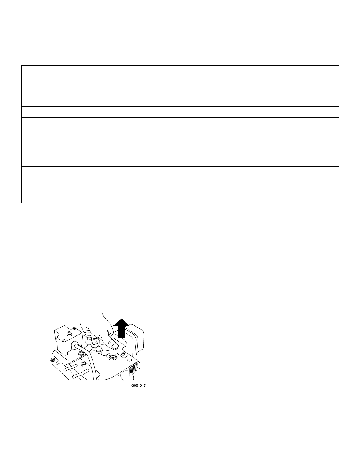
PreparingforMaintenance
1.Movethesnowthrowertoalevelsurface.
2.Stoptheengineandwaitforallmovingpartstostop.
3.Disconnectthesparkplugwire(Figure40).
Figure40
18
Page 19
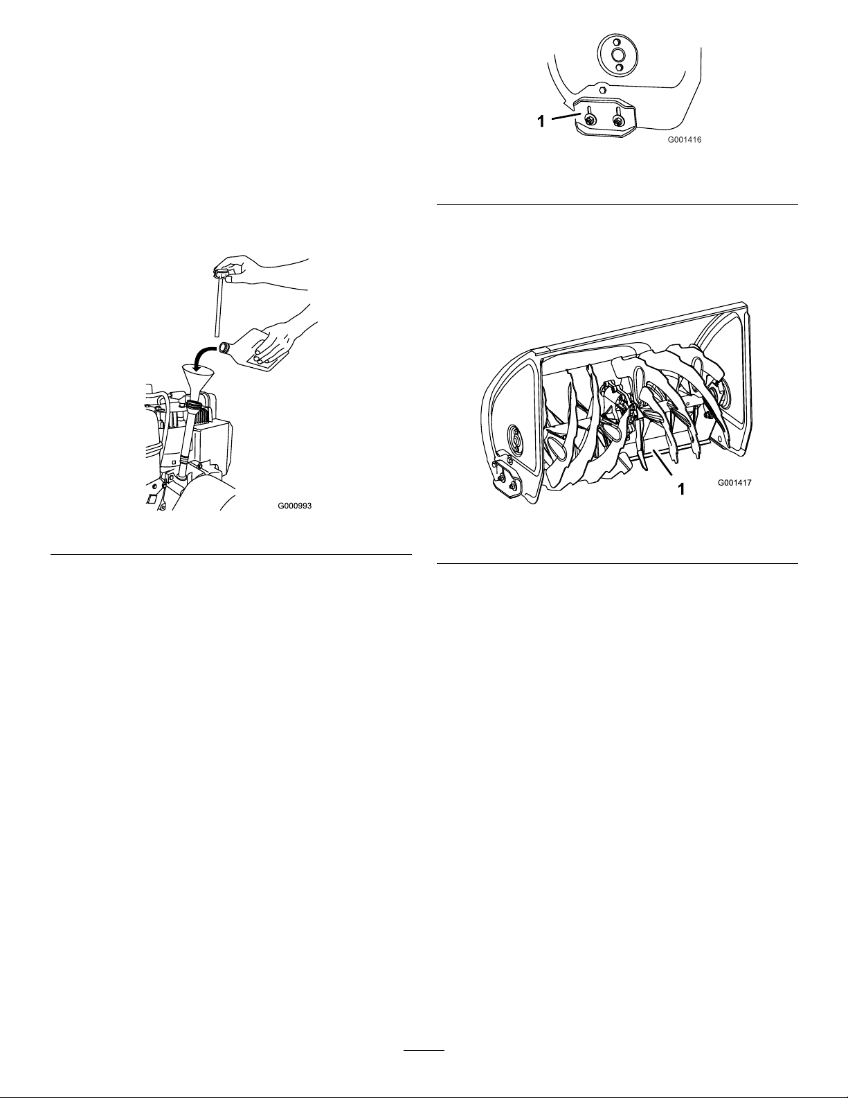
CheckingtheEngineOilLevel
ServiceInterval:Beforeeachuseordaily—Check
theengineoillevelandaddoilif
necessary.
1.Removethedipstick,wipeitclean,thenfullyinstall
thedipstick.
2.Removethedipstickandchecktheoillevel
Figure41).IftheoillevelisbelowtheAddmark
(
onthedipstick,addoil.RefertoFillingtheEngine
withOil.
Figure42
1.Skid
4.Pushdownonthehandlestoallowthepivoting
scrapertomovefullyforward,thensetthefrontof
thesnowthrowerdownsothatthefrontedgeofthe
pivotingscrapercontactstheground(Figure43).
Figure41
CheckingandAdjustingthe
Skids
ServiceInterval:Yearly—Checktheskidsandadjust
themifnecessary.
Checktheskidstoensurethattheaugerdoesnot
contactthepavedorgravelsurface.Adjusttheskidsas
neededtocompensateforwear.
1.Checkthetirepressure.RefertoCheckingtheTire
Pressure.
2.Movethesnowthrowertoalevelsurface.
3.Loosenthenutsthatsecurebothskidstothe
augersidesuntiltheskidsslideupanddowneasily
(Figure42).
Figure43
1.Pivotingscraper
5.Movetheskidsdownuntiltheyareevenwiththe
ground.
Note:Forasmoothsurface,youcansettheskids
slightlyhighertoincreasethescrapingaction,but
settheskidsfarenoughdowntopreventtheauger
bladesfromcontactingtheground.
Note:Thepivotingscraperonthesnowthroweris
notrecommendedforuseongravelsurfaces.Butif
youmustusethesnowthroweronagravelsurface,
adjusttheskidsfurtherdowntopreventthepivoting
scraperfrompickinguprocks.
6.Firmlytightenthenutsthatsecurebothskidstothe
augersides.
Note:Iftheskidsbecomeexcessivelyworn,you
canturnthemoverandsettheunusedsidetoward
thepavement.
19
Page 20
CheckingandAdjustingthe
CheckingandAdjustingthe
TractionCable
ServiceInterval:Aftertherst2hours—Inspect
thetractioncableandadjustitif
necessary.
Yearly—Inspectthetractioncable
andadjustorreplaceitifnecessary.
Ifthesnowthrowerdoesnotdriveintheforwardor
reversespeedsoritdriveswhenyoureleasethetraction
lever,adjustthetractioncable.
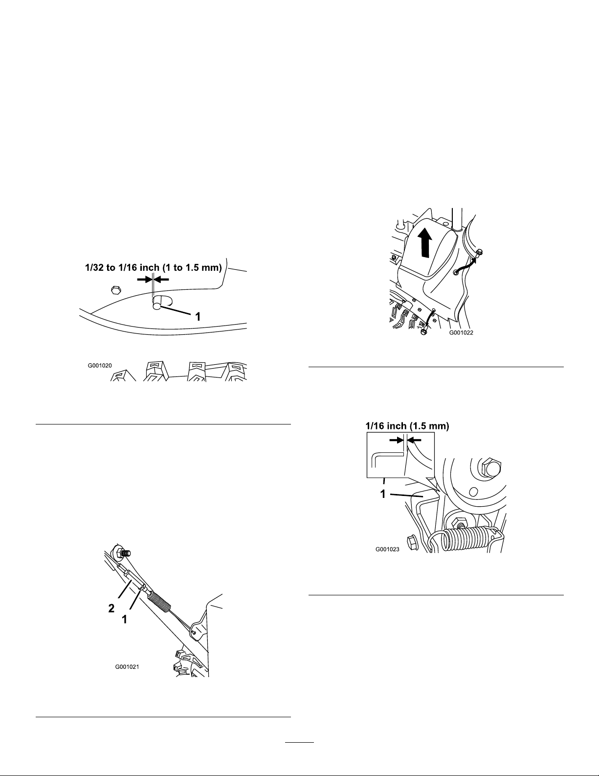
Withthetractionleverdisengaged,checkthepininthe
elongatedslotintheleftsideofthesnowthrowerabove
thetire.Thereshouldbeagapof1/32to1/16inch(1
to1.5mm)fromthefrontoftheslottothefrontedge
ofthepin(Figure44).
Auger/ImpellerCable
ServiceInterval:Aftertherst2hours—Inspectthe
auger/impellercableandadjustitif
necessary.
Yearly—Inspecttheauger/impeller
cableandadjustorreplaceitif
necessary.
1.Removethe2screwsfromtherightsideofthebelt
coverasshown.
2.Liftuptherightsideofthebeltcover(
Figure46).
Figure44
1.Pin
Ifthelefthand(traction)cableisnotproperlyadjusted,
dothefollowingsteps:
1.Loosenthejamnut.
2.Loosenortightentheturnbuckletoadjustthepin
untilitisthepropergapfromthefrontedgeofthe
slot.
3.Tightenthejamnut(Figure45).
Figure46
3.Withtheauger/impellerleverdisengaged,ensure
thatthegapbetweentheaugerclutchassemblyand
thetabis1/16inch(1.5mm)(Figure47).
Figure47
1.Tab
4.Iftheauger/impellercableisnotproperlyadjusted,
dothefollowingsteps:
Figure45
1.Jamnut2.Turnbuckle
5.Loosenthejamnut(Figure48).
20
Page 21
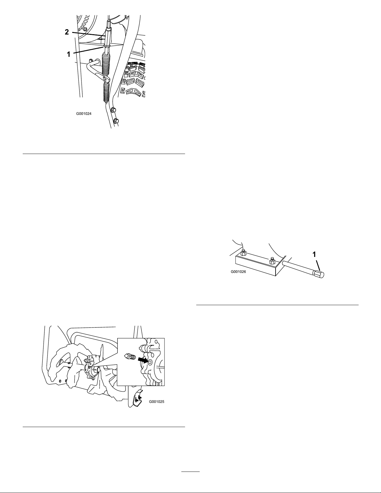
Figure48
1.Jamnut2.Turnbuckle
6.Loosenortightentheturnbucklethatadjuststhe
tensiononthecable(Figure48).
7.Adjusttheturnbuckleuntilyouobtaintheproper
gap.
8.Tightenthejamnut.
9.Insertthe2screwsyoupreviouslyremovedonthe
beltcover.
10.Iftheauger/impellercableisproperlyadjustedbut
aproblemremains,contactanAuthorizedService
Dealer.
5.Iftheoillevelislow,addGL-5orGL-6,SAE85-95
EPtransmissionoiltothegearboxuntilthepoint
ofoverow.
Note:Donotusesyntheticoil.
6.Installthepipepluginthegearbox.
ChangingtheEngineOil
ServiceInterval:Aftertherst2hours
Yearly
Ifpossible,runtheenginejustbeforechangingthe
oilbecausewarmoilowsbetterandcarriesmore
contaminants.
Max.ll:26oz.(0.77l),type:automotivedetergent
oilwithanAPIserviceclassicationofSF,SG,SH,SJ,
SL,orhigher.
•Fortemperaturesabove32°F(0°C),useSAE30W .
•Fortemperaturesbetween0°Fand32°F(-18°Cto
0°C),useSAE5W30orSAE10W .
•Forairtemperaturesbelow0°F(-18°C),use
SAE0W30.
1.Cleantheareaaroundtheoildraincap(Figure50).
CheckingtheAugerGearbox
OilLevel
ServiceInterval:Yearly—Checktheaugergearboxoil
andaddoilifnecessary.
1.Movethesnowthrowertoalevelsurface.
2.Cleantheareaaroundthepipeplug(
Figure49
3.Removethepipeplugfromthegearbox.
4.Checktheoillevelinthegearbox.Theoilshouldbe
atthepointofoverowingatthelleropening.
Figure49).
Figure50
1.Oildraincap
2.Slideanoildrainpanunderthedrainextensionand
removetheoildraincap.
3.Draintheoil.
Note:Disposeoftheusedoilproperlyatalocal
recyclingcenter.
4.Installtheoildraincap.
5.Fillthecrankcasewithoil.RefertoFillingthe
EngineCrankcasewithOil.
LubricatingtheHexShaft
ServiceInterval:Yearly
Lightlylubricatethehexshaftyearlywithautomotive
engineoil(Figure51).
21
Page 22
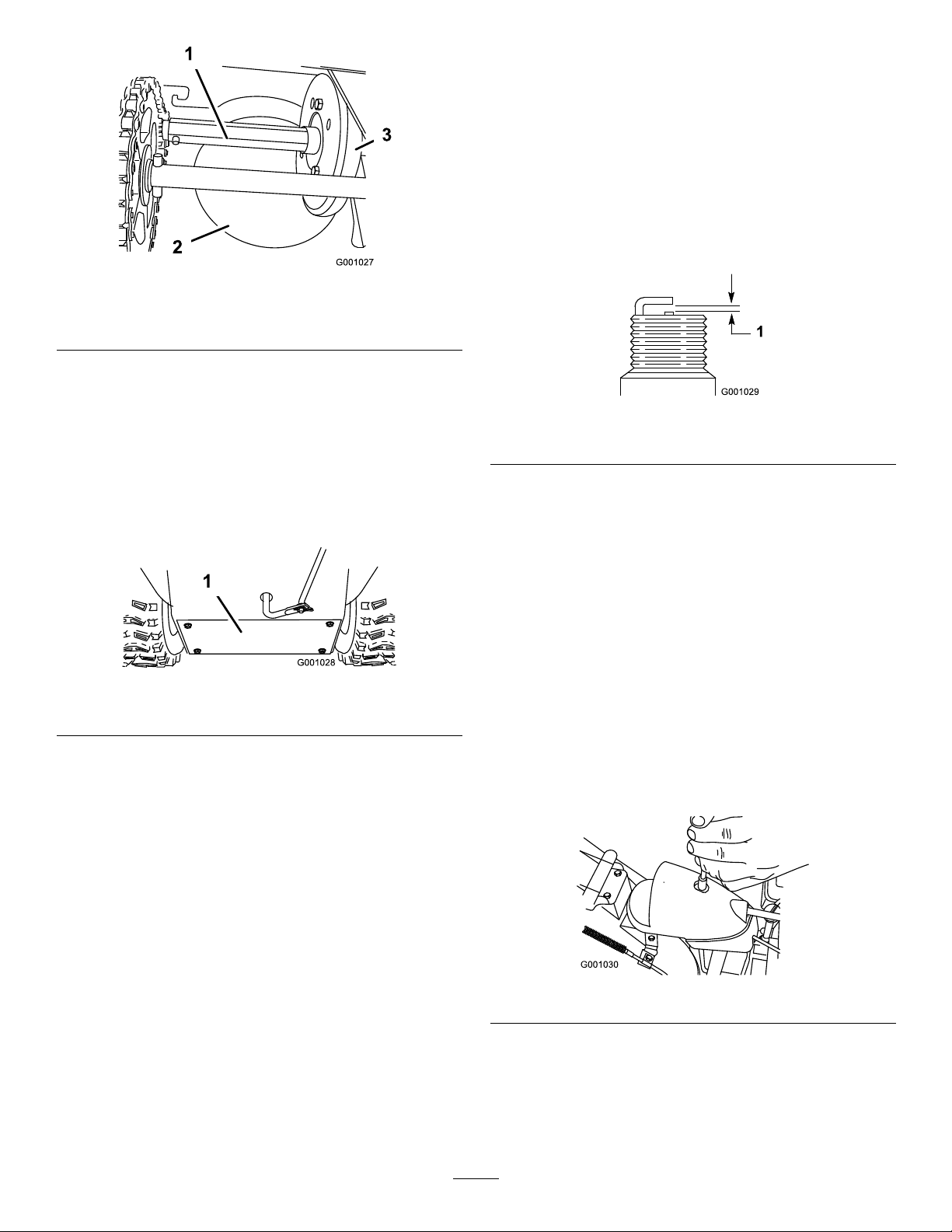
Figure51
1.Hexshaft
2.Aluminumfrictionplate
3.Rubberwheel
Important:Donotgetoilontherubberwheel
orthealuminumfrictiondriveplatebecausethe
tractiondrivewillslip(Figure51).
1.Drainthegasolinefromthefueltank.
1.Cleanaroundthebaseofthesparkplug.
2.Removethesparkplug.
3.Examinethesparkplugandreplaceitifitiscracked,
fouled,dirty,oriftheelectrodesareworn.
Important:Donotcleantheelectrodesbecause
gritcouldenterthecylinderanddamagethe
engine.
4.Setthegapbetweentheelectrodesonthesparkplug
at0.030inch(0.76mm)(Figure53).
Figure53
1.0.030inch(0.76mm)
2.Tipthesnowthrowerforwardontoitsaugerhousing
andblockitsothatitcannotfall.
3.Removethebackcover(Figure52).
Figure52
1.Backcover
4.MovethespeedselectorlevertoPositionR2.
5.Dipyourngerinautomotiveengineoilandlightly
lubricatehexshaft.
6.MovethespeedselectorlevertoPosition6.
7.Lubricatetheotherendofthehexshaft.
8.Movethespeedselectorleverforwardandrearward
afewtimes.
5.Installthesparkplugbyhandandthentorqueitto
15ft-lb(20.4N·m).
Note:Ifyoudonothaveatorquewrench,tighten
theplugrmly.
AdjustingtheDischargeChute
Latch
Ifthedischargechutedoesnotlockintothedesired
positionordoesnotunlocksothatyoucanmoveitto
anotherposition,adjustthedischargechutelatch.
1.Removethefasteneronthegearcover(Figure54),
liftthefrontofthecoverup,andslideitbackand
outoftheway.
9.Installthebackcoverandreturnthesnowthrower
totheoperatingposition.
InspectingandReplacingthe
SparkPlug
ServiceInterval:Yearly—Inspectthesparkplug.
Replaceand/orgapitifnecessary.
UseaChampionRN4Corequivalentsparkplug.
Figure54
2.Loosentheboltonthecableclamp(Figure55).
22
Page 23
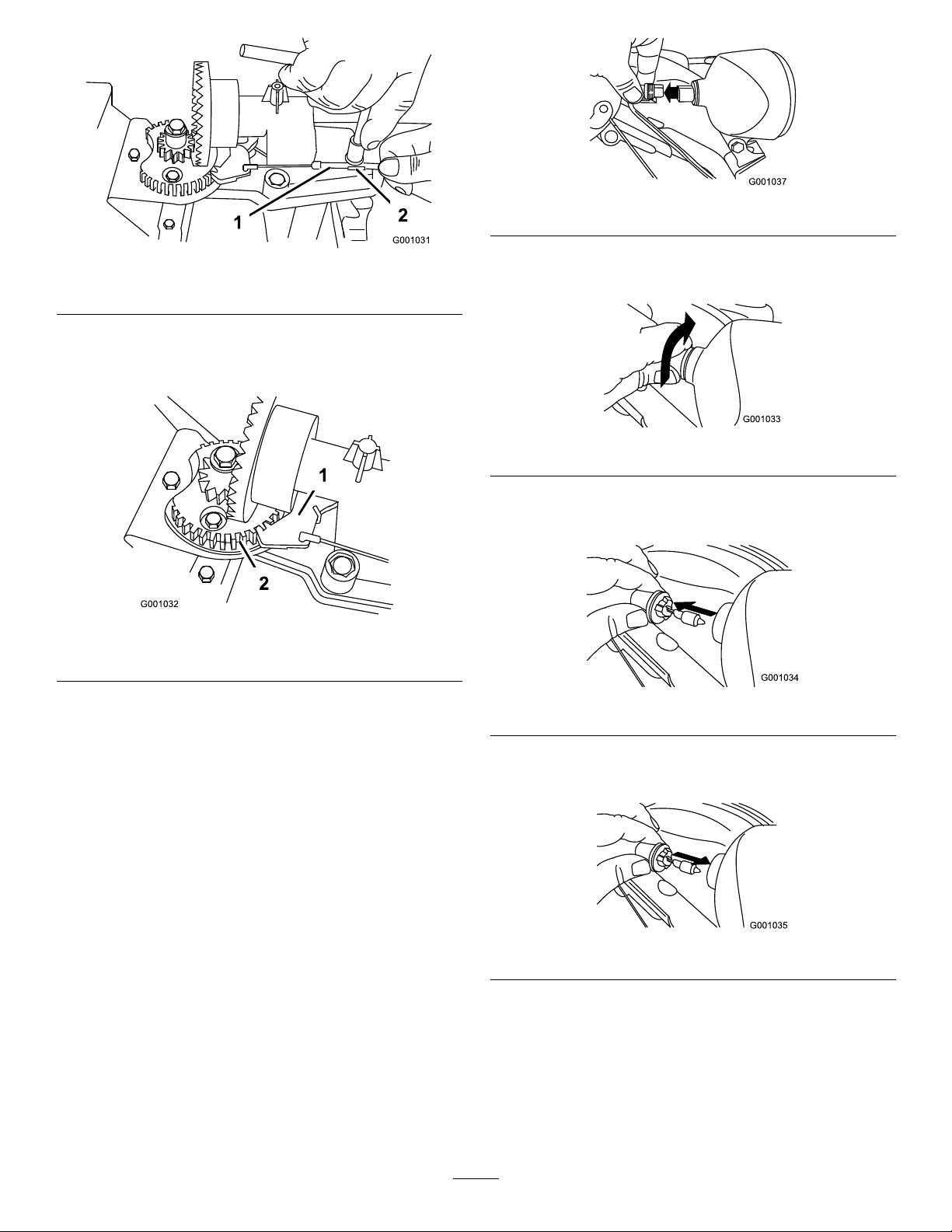
Figure57
Figure55
1.Cableconduit2.Cableclamp
3.Graspthecableconduitandmoveittowardthefront
ofthemachineuntilthedischargechutelatchfully
engagesthegearteeth(Figure55andFigure56).
Figure56
1.Dischargechutelatch
2.Gearteeth
Note:Thelatchisspringloadedandwillnaturally
moveintotheteethofthegear(Figure56).
4.Removeanyslackinthecablebypullingthecable
conduitrearward.
5.Tightentheboltonthecableclamp.
6.Installandsecurethegearcover.
2.Turnthebaseofthebulbcounterclockwiseuntilit
stops(Figure58).
Figure58
3.Removethebulbstraightoutfromthebackofthe
headlight(Figure59).
Figure59
4.Insertanewbulbintothebackoftheheadlight
(Figure60).
ReplacingtheDriveBelts
Iftheauger/impellerdrivebeltorthetractiondrivebelt
becomesworn,oil-soaked,orotherwisedamaged,go
towww.Toro.comforadditionalserviceinformationor
haveanAuthorizedServiceDealerreplacethebelt.
ReplacingtheHeadlightBulb
UseaGE89216Whalogenlightbulb.Donottouch
thebulbwithyourhandsorallowdirtormoistureto
comeintocontactwiththebulb.
1.Removethewireconnectorfromthebackofthe
headlight(
Figure57).
Figure60
5.Turnthebaseofthebulbclockwiseuntilitissnug
(Figure61).
23
Page 24
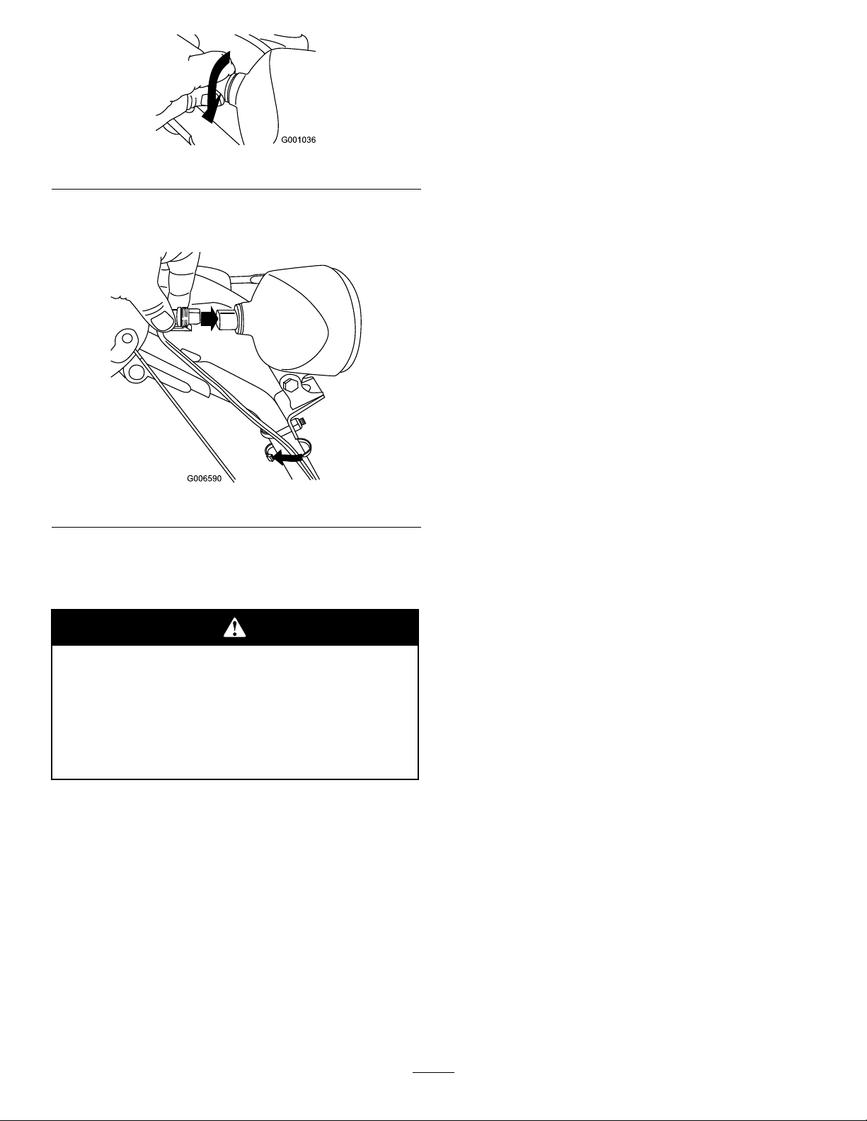
4.Openthefuelshutoffvalveandallowthefuelto
drainoutofthefueltankintoanapprovedfuel
container.
5.Installthefuellineontothefuelshutoffvalveand
secureitwithahoseclamp.
Figure61
6.Insertthewireconnectorstraightintothebackof
theheadlightuntilitissecurelyinplace(
Figure62
Figure62).
6.Runthesnowthroweruntiltheenginestopsfrom
runningoutoffuel.
7.Primetheengineandstartitagain.
8.Allowtheenginetorununtilitstops.Whenyoucan
nolongerstarttheengine,itissufcientlydry.
9.Stoptheengineandallowittocool.
10.Removetheignitionkey.
11.Disconnectthesparkplugwire.
12.Removethesparkplug,add1oz.(30ml)ofoil
throughthesparkplughole,andpullthestarterrope
slowlyseveraltimestodistributeoilthroughoutthe
cylindertopreventcylindercorrosionduringthe
off-season.
13.Looselyinstallthesparkplug.
14.Disposeofanyunusedfuelproperly.Recycleit
accordingtolocalcodes,oruseitinyourautomobile.
Note:Donotstorestabilizedfuelformorethan
90days.
Storage
•Gasolinevaporscanexplode.
•Donotstoregasolinemorethan30days.
•Donotstorethesnowthrowerinan
enclosurenearanopename.
•Allowtheenginetocoolbeforestoringit.
PreparingtheSnowthrower
forStorage
1.Onthelastrefuelingoftheyear,addfuelstabilizer
tofreshfuelasdirectedbytheenginemanufacturer.
2.Runtheenginefor10minutestodistributethe
conditionedfuelthroughthefuelsystem.
3.Loosenthehoseclampthatsecuresthefuellineto
thevalveandslidethefuellineoffthefuelshutoff
valve.
15.Cleanthesnowthrowerthoroughly.
16.Touchupchippedsurfaceswithpaintavailable
fromanAuthorizedServiceDealer.Sandaffected
areasbeforepainting,andusearustpreventativeto
preventthemetalpartsfromrusting.
17.Tightenallloosescrews,bolts,andlocknuts.Repair
orreplaceanydamagedparts.
18.Coverthesnowthrowerandstoreitinaclean,dry
placeoutofthereachofchildren.Allowtheengine
tocoolbeforestoringitinanyenclosure.
RemovingtheSnowthrower
fromStorage
1.Removethesparkplugandspintheenginerapidly
usingthestartertoblowtheexcessoilfromthe
cylinder.
2.Installthesparkplugbyhandandthentorqueitto
15ft-lb(20.4N·m).
3.Connectthesparkplugwire.
4.Performtheannualmaintenanceproceduresasgiven
intheRecommendedMaintenanceSchedule.
24
Page 25

Troubleshooting
Problem
Electricstarterdoesnotturn(electric-start
modelsonly)
Enginedoesnotstartorstartshard
PossibleCauseCorrectiveAction
1.Thepowercordisdisconnectedatthe
outletorthesnowthrower.
2.Thepowercordisworn,corroded,or
damaged.
3.Thepoweroutletisnotenergized.
1.Thekeyisnotintheignitionorisinthe
Stopposition.
2.ThechokeisintheOffpositionandthe
primerhasnotbeenpressed.
3.Thefuelshutoffvalveisnotopen.3.Openthefuelshutoffvalve.
4.ThethrottleisnotintheFastposition.4.MovethethrottletotheFastposition.
5.Thefueltankisemptyorthefuel
systemcontainsstalefuel.
6.Thesparkplugwireislooseor
disconnected.
7.Thesparkplugispitted,fouled,orthe
gapisincorrect.
8.Thefuelventcapisrestricted.
9.Theengineoillevelintheengine
crankcaseistoolowortoohigh.
1.Connectthepowercordtotheoutlet
and/orthesnowthrower.
2.Replacethepowercord.
3.Haveaqualiedelectricianenergize
theoutlet.
1.Insertthekeyintotheignitionandturn
ittotheOnposition.
2.MovethechoketotheOnpositionand
presstheprimer3times.
5.Drainand/orllthefueltankwithfresh
gasoline(notmorethan30daysold).
Iftheproblempersists,contactan
AuthorizedServiceDealer.
6.Connectthewiretothesparkplug.
7.Checkthesparkplugandadjustthe
gapifnecessary .Replacethespark
plugifitispitted,fouled,orcracked.
8.Removetheventrestrictionorreplace
thefuelcap.
9.Addordrainoiltoadjusttheoillevelin
theenginecrankcasetotheFullmark
onthedipstick.
Enginerunsrough
Engineruns,butthesnowthrower
dischargessnowpoorlyornotatall
1.ThechokeisintheOnposition.1.MovethechoketotheOffposition.
2.Thefuelshutoffvalveisnotcompletely
open.
3.Thefueltankisnearlyemptyor
containsstalefuel.
4.Thesparkplugwireisloose.
5.Thesparkplugispitted,fouled,orthe
gapisincorrect.
6.Theengineoillevelintheengine
crankcaseistoolowortoohigh.
1.ThethrottleisnotintheFastposition
whenthrowingsnow .
2.Thesnowthrowerismovingtoofastto
clearthesnow.
3.Y ouaretryingtoremovetoomuch
snowperswath.
4.Y ouaretryingtoremoveextremely
heavyorwetsnow.
5.Thedischargechuteisplugged.5.Unclogthedischargechute.
6.Theauger/impellerdrivebeltisloose
orisoffthepulley.
2.Openthefuelshutoffvalve.
3.Drainandllthefueltankwithfresh
gasoline(notmorethan30daysold).
Iftheproblempersists,contactan
AuthorizedServiceDealer.
4.Connectthewiretothesparkplug.
5.Checkthesparkplugandadjustthe
gapifnecessary .Replacethespark
plugifitispitted,fouled,orcracked.
6.Addordrainoiltoadjusttheoillevelin
theenginecrankcasetotheFullmark
onthedipstick.
1.MovethethrottletotheFastposition.
2.Shiftthesnowthrowerintoalowergear.
3.Reducetheamountofsnowremoved
perswath.
4.Don’toverloadthesnowthrowerwith
extremelyheavyorwetsnow.
6.Installand/oradjusttheauger/impeller
drivebelt;refertowww.Toro.com
forservicinginformationortakethe
snowthrowertoanAuthorizedService
Dealer.
25
Page 26

Problem
7.Theauger/impellerdrivebeltisworn
orbroken.
PossibleCauseCorrectiveAction
7.Replacetheauger/impellerdrivebelt;
refertowww.Toro.comforservicing
informationortakethesnowthrowerto
anAuthorizedServiceDealer.
Dischargechuteeitherdoesnotlockinto
placeordoesnotmove
snowoffthesurface
1.Thedischargechutelatchisnot
properlyadjusted.
1.Theskidsand/orscraperarenot
properlyadjusted.
2.Thepressureinthetiresisnotequal.
1.Adjustthedischargechutelatch.
1.Adjusttheskidsand/orthescraper. Snowthrowerdoesnotproperlyclearthe
2.Checkandadjustthepressureinone
orbothtires.
26
Page 27

International Distributor List—Consumer Products
Distributor:
Atlantis Su ve Sulama Sisstemleri Lt Turkey
Balama Prima Engineering Equip
B-Ray Corporation
Casco Sales Company
Ceres S.A
CSSC Turf Equipment (pvt) Ltd
Cyril Johnston & Co Nothern Ireland
Equiver Mexico
Femco S.A.
G.Y.K. Company ltd.
Geomechaniki of Athens
Guandong Golden Star China
Hako Gorund and Garden Sweden
Hydroturf Int. Co Dubai United Arab Emirates
Hydroturf Egypt LLC
Ibea S.p.A. Italy
Irriamc
Jean Heybroek b.v. Netherlands
Lely (U.K. ) Limited
Maquiver S.A.
Maruyama Mfg. Co. Inc.
Metra Kft
Mounteld a.s. Czech Republic
Munditol S.A.
Oslinger Turf Equipment SA Ecuador
Oy Hako Ground and Garden Ab Finland
Parkland Products Ltd New Zealand
Prochaska & Cie
RT Cohen 2004 Ltd Israel
Riversa Spain
Roth Motorgerate GmBh & Co
Sc Svend Carlsen A/S Denmark
Solvert S.A.S
Spypros Stavrinides Limited
Surge Systems India Limited India
T-Markt Logistics Ltd
Toro Australia Australia
Toro Europe BVBA
Country:
Hong Kong 852 2155 2163
Korea 82 32 551 2076
Puerto Rico
Costa Rica
Sri Lanka
Guatemala
Japan
Greece 30 10 935 0054
Egypt
Portugal
United Kingdom
Colombia
Japan
Hungary
Argentina
Austria
Germany 49 7144 2050
France
Cyprus 357 22 434131
Hungary
Belgium
Phone Number:
90 216 344 86 74
787 788 8383
506 239 1138
94 11 2746100
44 2890 813 121
52 55 539 95444
502 442 3277
81 726 325 861
86 20 876 51338
46 35 10 0000
97 14 347 9479
202 519 4308
39 0331 853611
351 21 238 8260
31 30 639 4611
44 1480 226 800
57 1 236 4079
81 3 3252 2285
36 1 326 3880
420 255 704 220
54 11 4 821 9999
593 4 239 6970
358 987 00733
64 3 34 93760
43 1 278 5100
972 986 17979
34 9 52 83 7500
45 66 109 200
33 1 30 81 77 00
91 1 292299901
36 26 525 500
61 3 9580 7355
32 14 562 960
374-0102 Rev A
Page 28

The Toro Warranty
Conditions and Products Covered
The Toro® Company and its afliate, Toro Warranty Company, pursuant to
an agreement between them, jointly promises to the original purchaser* to
repair any Toro Product used for normal residential purposes* if defective in
materials or workmanship. The following time periods apply from the date
of original purchase:
Products
Walk Power Mowers
Rear Engine Riders 2-year limited warranty
Lawn & Garden Tractors
Electric Hand Held Products
Snowthrowers
Consumer Zero Turn
* “Original purchaser” means use the person who originally purchased Toro
products.
* “Normal residential purposes” means use of the product on the same lot as
your home. Use at more than one location is considered commercial use, and
the commercial use warranty would apply.
Warranty Period
2-year limited warranty
2-year limited warranty
2-year limited warranty
2-year limited warranty
2-year limited warranty
Limited Warranty for Commercial Use
Toro Consumer Products and attachments used for commercial, institutional,
or rental use are warranted against defects in materials or workmanship for the
following time periods from the date of original purchase:
Products
Walk Power Mowers
Rear Engine Riders 90 day warranty
Lawn & Garden Tractors
Electric Hand Held Products
Snowthrowers
Consumer Zero Turn
Warranty Period
90 day warranty
90 day warranty
90 day warranty
90 day warranty
45 day warranty
Instructions for Obtaining Warranty Service
If you think that your Toro Product contains a defect in materials or
workmanship, follow this procedure:
1. Contact your seller to arrange service of the product. If for any reason
it is impossible for you to contact your seller, you may contact any Toro
Authorized Distributor to arrange service.
2. Bring the product and your proof of purchase (sales receipt) to your seller
or the Service Dealer.
If for any reason you are dissatised with the Service Dealer’s analysis or with the
assistance provided, contact the Toro importer or contact us at:
Customer Care Department, Consumer Division
Toro Warranty Company
8111 Lyndale Avenue South
Bloomington, MN 55420-1196
Manager: Technical Product Support: 001-952-887-8248
See attached Distributor List
Owner Responsibilities
You must maintain your Toro Product by following the maintenance procedures
described in the operator’s manual. Such routine maintenance, whether
performed by a dealer or by you, is at your expense.
Items and Conditions Not Covered
This express warranty does not cover:
• Cost of regular maintenance service or parts, such as lters, fuel, lubricants,
tune-up parts, blade sharpening, brake and clutch adjustments.
• Any product or part which has been altered or misused or required
replacement or repair due to normal wear, accidents, or lack of proper
maintenance.
• Repairs necessary due to improper fuel, contaminants in the fuel system, or
failure to properly prepare the fuel system prior to any period of non-use
over three months.
• Engine and transmission. These are covered by the appropriate
manufacturer’s guarantees with separate terms and conditions.
All repairs covered by this warranty must be performed by an Authorized Toro
Service Dealer using Toro approved replacement parts.
General Conditions
The purchaser is covered by the national laws of each country. The rights to
which the purchaser is entitled with the support of these laws are not restricted
by this warranty.
374-0101 Rev A
 Loading...