

Page 1
PowerMax
ModelNo.38597—SerialNo.311000001andUp
ModelNo.38629—SerialNo.311000001andUp
ModelNo.38637—SerialNo.311000001andUp
ModelNo.38639—SerialNo.311000001andUp
ModelNo.38657—SerialNo.311000001andUp
®
Snowthrowers
FormNo.3365-665RevA
Operator'sManual
Introduction
Thismachineisintendedtobeusedbyresidential
homeownersorprofessional,hiredoperators.It
isdesignedprimarilyforremovingsnowfrom
pavedsurfaces,suchasdrivewaysandsidewalks,
andothersurfacesfortrafconresidentialor
commercialproperties.Itisnotdesignedfor
removingmaterialsotherthansnow,norisamodel
withapivotingscraperdesignedforclearingoff
gravelsurfaces.
Readthisinformationcarefullytolearnhowtooperate
andmaintainyourmachineproperlyandtoavoidinjury
andmachinedamage.Youareresponsibleforoperating
themachineproperlyandsafely.
YoumaycontactTorodirectlyatwww .Toro.comfor
machineandaccessoryinformation,helpndinga
dealer,ortoregisteryourmachine.
Wheneveryouneedservice,genuineToroparts,or
additionalinformation,contactanAuthorizedService
DealerorToroCustomerServiceandhavethemodel
andserialnumbersofyourmachineready .
identiesthelocationofthemodelandserialnumbers
onthemachine.Writethenumbersinthespace
provided.
Figure1
ModelNo.
SerialNo.
Thismanualidentiespotentialhazardsandhas
safetymessagesidentiedbythesafetyalertsymbol
(Figure2),whichsignalsahazardthatmaycauseserious
injuryordeathifyoudonotfollowtherecommended
precautions.
Figure2
1.Safetyalertsymbol
Thismanualuses2wordstohighlightinformation.
Importantcallsattentiontospecialmechanical
informationandNoteemphasizesgeneralinformation
worthyofspecialattention.
ReplacementEngineOwner’sManualsmaybe
orderedthroughtheenginemanufacturer.
1.Modelandserialnumberlocation
©2010—TheT oro®Company
8111LyndaleAvenueSouth
Bloomington,MN55420
Figure1
Registeratwww.Toro.com.
OriginalInstructions(EN)
PrintedintheUSA
AllRightsReserved
Page 2
Safety
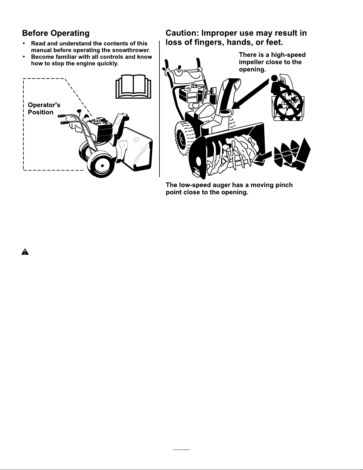
BeforeOperating
?
?
Readandunderstandthecontentsofthis
manualbeforeoperatingthesnowthrower .
Becomefamiliarwithallcontrolsandknow
howtostoptheenginequickly .
Operator 's
Position
Thelow-speedaugerhasamovingpinch
pointclosetotheopening.
Caution:Improperusemayresultin
lossoffingers,hands,orfeet.
Thereisahigh-speed
impellerclosetothe
opening.
ThismachinemeetsorexceedstheISOstandard
8437ineffectatthetimeofproduction.
Readandunderstandthecontentsofthismanual
beforetheengineiseverstarted.
Thisisthesafetyalertsymbol.Itisusedtoalert
youtopotentialpersonalinjuryhazards.Obeyall
safetymessagesthatfollowthissymboltoavoid
possibleinjuryordeath.
Improperlyusingormaintainingthismachine
couldresultininjuryordeath.Toreducethis
potential,complywiththefollowingsafety
instructions.
Training
•Readtheoperatingandserviceinstructionmanual
carefully.Bethoroughlyfamiliarwiththecontrols
andtheproperuseofthemachine.Knowhowto
stopthemachineanddisengagethecontrolsquickly.
•Neverallowchildrentooperatethemachine.Never
allowadultstooperatethemachinewithoutproper
instruction.
•Keeptheareaofoperationclearofallpersons,
particularlysmallchildren,andpets.
Preparation
•Thoroughlyinspecttheareawherethemachineis
tobeusedandremovealldoormats,sleds,boards,
wires,andotherforeignobjects.
•Disengageallclutchesandshiftintoneutralbefore
startingtheengine.
•Donotoperatethemachinewithoutwearing
adequatewintergarments.Wearfootwearwhichwill
improvefootingonslipperysurfaces.
•Handlefuelwithcare;itishighlyammable.
–Useanapprovedfuelcontainer.
–Neveraddfueltoarunningorhotengine.
–Fillfueltankoutdoorswithextremecare.Never
–Replacegasolinecapssecurelyandwipeup
•Adjustthecollectorhousingheighttocleargravel
orcrushedrocksurface.
•Neverattempttomakeanyadjustmentswhile
theengineisrunning(exceptwherespecically
recommendedbymanufacturer).
•Letengineandmachineadjusttooutdoor
temperaturesbeforestartingtoclearsnow.
llfueltankindoors.
spilledfuel.
•Exercisecautiontoavoidslippingorfalling,
especiallywhenoperatinginreverse.
•Theoperationofanypoweredmachinecanresultin
foreignobjectsbeingthrownintotheeyes.Always
2
Page 3

wearsafetyglassesoreyeshieldsduringoperationor
whileperforminganadjustmentorrepair.
•Neveroperatethemachinewithoutgoodvisibility
orlight.Alwaysbesureofyourfooting,andkeepa
rmholdonthehandles.Walk;neverrun.
Operation
•Donotputhandsorfeetnearorunderrotatingparts.
Keepclearofthedischargeopeningatalltimes.
•Exerciseextremecautionwhenoperatingonor
crossinggraveldrives,walks,orroads.Stayalertfor
hiddenhazardsortrafc.
•Afterstrikingaforeignobject,stoptheengine,
removethewirefromthespark-plug,thoroughly
inspectthemachineforanydamage,andrepairthe
damagebeforerestartingandoperatingthemachine.
•Ifthemachineshouldstarttovibrateabnormally,
stoptheengineandcheckimmediatelyforthecause.
Vibrationisgenerallyawarningoftrouble.
•Stoptheenginewheneveryouleavetheoperating
position,beforeuncloggingthecollector/impeller
housingordischargeguide,andwhenmakingany
repairs,adjustments,orinspections.
•Whencleaning,repairing,orinspecting,makecertain
thecollector/impellerandallmovingpartshave
stopped.Disconnectthespark-plugwire,andkeep
thewireawayfromtheplugtopreventaccidental
starting.
•Donotruntheengineindoors,exceptwhenstarting
itandformovingthemachineinoroutofthe
building.Opentheoutsidedoors;exhaustfumes
aredangerous.
•Neveroperatethemachinewithoutgoodvisibility
orlight.
•Takeallpossibleprecautionswhenleavingthe
machineunattended.Shiftintoneutral,setthe
parkingbrake,stoptheengineandremovethekey.
MaintenanceandStorage
•Checkallfastenersatfrequentintervalsforproper
tightnesstobesurethemachineisinsafeworking
condition.
•Neverstorethemachinewithfuelinthefueltank
insideabuildingwhereignitionsourcesarepresent
suchashotwaterandspaceheaters,clothesdryers,
etc.Allowtheenginetocoolbeforestoringinany
enclosure.
•Alwaysrefertoowner’sguideinstructionsfor
importantdetailsifthemachineistobestoredfor
anextendedperiod.
•Maintainorreplacesafetyandinstructionslabels,
asnecessary.
•Runthemachineafewminutesafterthrowingsnow
topreventfreeze-upofthecollector/impeller.
ToroSnowthrowerSafety
•Donotclearsnowacrossthefaceofslopes.Exercise
extremecautionwhenchangingdirectiononslopes.
Donotattempttoclearsteepslopes.
•Neveroperatethemachinewithoutproperguards,
plates,orothersafetyprotectivedevicesinplace.
•Neveroperatethemachinenearglassenclosures,
automobiles,windowwells,drop-offs,etc.without
properadjustmentofthesnowdischargeangle.
Keepchildrenandpetsaway.
•Donotoverloadthemachinecapacitybyattempting
toclearsnowattoofastarate.
•Neveroperatethemachineathightransportspeeds
onslipperysurfaces.Usecarewhenreversing.
•Neverdirectdischargeatbystandersorallowanyone
infrontofthemachine.
•Disengagepowertothecollector/impellerwhen
machineistransportedornotinuse.
•Useonlyattachmentsandaccessoriesapprovedby
themanufacturerofmachine(suchaswheelweights,
counterweights,cabs,etc.).
Thefollowinglistcontainssafetyinformationspecic
toToroproductsorothersafetyinformationthatyou
mustknow.
•Rotatingrotorbladescaninjurengersor
hands.Staybehindthehandlesandawayfromthe
dischargeopeningwhileoperatingthemachine.
Keepyourface,hands,feet,andanyotherpart
ofyourbodyorclothingawayfrommovingor
rotatingparts.
•Beforeadjusting,cleaning,repairing,andinspecting
themachine,andbeforeuncloggingthedischarge
chute,stoptheengine,removethekey ,andwait
forallmovingpartstostop.
•Usethesnowcleanouttool,notyourhands,to
removeobstructionsfromthedischargechute.
•Beforeleavingtheoperatingposition,stopthe
engine,removethekey,andwaitforallmovingparts
tostop.
•Donotwearloose-ttingclothingthatcouldget
caughtinmovingparts.
3
Page 4
•Ifashield,safetydevice,ordecalisdamaged,
illegible,orlost,repairorreplaceitbeforebeginning
operation.Also,tightenanyloosefasteners.
SafetyandInstructional
Decals
•Donotsmokewhilehandlinggasoline.
•Donotusethemachineonaroof.
•Donottouchtheenginewhileitisrunningorsoon
afterithasstoppedbecausetheenginemaybehot
enoughtocauseaburn.
•Performonlythosemaintenanceinstructions
describedinthismanual.Beforeperformingany
maintenance,service,oradjustment,stoptheengine,
removethekey,anddisconnectthewirefromthe
sparkplug.Ifmajorrepairsareeverneeded,contact
anAuthorizedServiceDealer.
•Donotchangethegovernorsettingsontheengine.
•Whenstoringthemachineformorethan30days,
drainthefuelfromthefueltanktopreventa
potentialhazard.Storefuelinanapprovedfuel
container.Removethekeyfromtheignitionswitch
beforestoringthemachine.
•PurchaseonlygenuineTororeplacementpartsand
accessories.
SoundPressure
Thismachinehasasoundpressurelevelattheoperator’s
earof87dBA(allmodelsexcept38657)or91dBA
(model38657only),whichincludesanUncertaintyValue
(K)of1dBA.Thesoundpressurelevelwasdetermined
accordingtotheproceduresoutlinedinENISO11201.
Important:Safetyandinstructiondecalsare
locatednearareasofpotentialdanger.Replace
damageddecals.
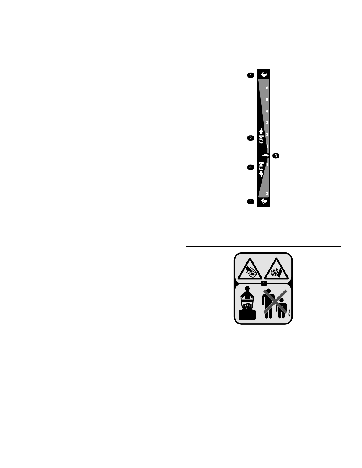
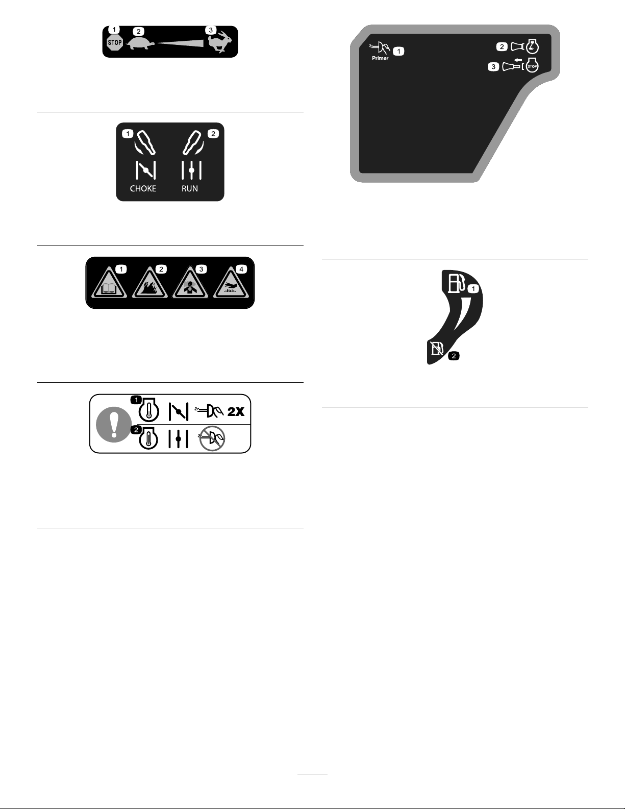
106-4525
Reorderpartno.112-6633
1.Fast
2.Forwardspeeds4.Reversespeeds
3.Slow
SoundPower
Thismachinehasaguaranteedsoundpowerlevelof
102dBA(allmodelsexcept38657)or105dBA(model
38657only),whichincludesanUncertaintyValue(K)
of2dBA.Thesoundpowerlevelwasdetermined
accordingtotheproceduresoutlinedinENISO3744.
Vibration
Measuredvibrationlevelforthelefthand=3.4m/s
modelsexcept38657)or7.1m/s
Measuredvibrationlevelfortherighthand=4.5m/s
(allmodelsexcept38657)or5.5m/s
only)
UncertaintyValue(K)=2.3m/s
38657)or2.8m/s
2
(model38657only)
Themeasuredvaluesweredeterminedaccordingtothe
proceduresoutlinedinENISO20643.
2
(model38657only)
2
(model38657
2
(allmodelsexcept
107-3040
1.Cuttingdismemberment,impellerandcutting
dismemberment,augerhazards—keepbystandersasafe
2
(all
2
4
distancefromthemachine.
Page 5
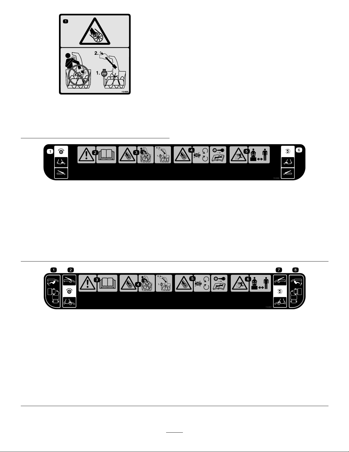
112-6625
Reorderpartno.112-6629
1.Cutting/dismembermenthazard,impeller—donotplace
yourhandinthechute;stoptheenginebeforeleavingthe
operator’sposition,usethetooltoclearthechute.
112-6626
1.Tractiondrive—squeezetheleverto
engage;releasethelevertodisengage.
2.Warning—readtheOperator’sManual.4.Cutting/dismembermenthazard,
3.Cutting/dismembermenthazard,
impeller—donotplaceyourhandinthe
chute;stoptheenginebeforeleaving
theoperator’sposition,usethetool
clearthechute.
impellerandauger—stayawayfrom
movingparts,keepallguardsand
shieldsinplace;removetheignition
keyandreadtheinstructionsbefore
servicingorperformingmaintenance.
5.Thrownobjecthazard—keep
bystandersasafedistancefromthe
machine.
6.Auger/impellerdrive—squeezethe
levertoengage;releasetheleverto
disengage.
1.Leftturncontrol
2.Tractiondrive—squeeze
thelevertoengage;release
thelevertodisengage.
3.Warning—readthe
Operator’sManual.
4.Cutting/dismemberment
hazard,impeller—do
notplaceyourhand
inthechute;stopthe
enginebeforeleavingthe
operator’sposition,usethe
tooltoclearthechute.
112-6627
5.Cutting/dismemberment
hazard,impeller—keep
awayfrommovingparts;
removetheignitionkeyand
readtheinstructionsbefore
servicingorperforming
maintenance.
6.Thrownobject
hazard—keepbystanders
asafedistancefromthe
machine.
7.Auger/impeller
drive—squeezetheleverto
engage;releasethelever
todisengage.
8.Rightturncontrol
5
Page 6
Briggs&StrattonPartNo.273676
1.Stop
2.Slow
3.Fast
Briggs&StrattonPartNo.275949
1.Chokeon(Choke)2.Chokeoff(Run)
Briggs&StrattonPartNo.276925
1.Warning—readthe
Operator’sManual.
2.Warning—rehazard.
3.Warning—toxicgas
inhalationhazard.
4.Warning—hot
surface/burnhazard.
Briggs&StrattonPartNo.277588
1.Primer3.Ignitionkeyout
(Engine—Stop)
2.Ignitionkeyin
(Engine—Run)
Briggs&StrattonPartNo.278866
1.Fuel—On2.Fuel—Off
Briggs&StrattonPartNo.277566
1.Whenstartingacold
engine,closethechoke
andpresstheprimertwo
times.
2.Whenstartingawarm
engine,openthechoke
anddonotpressthe
primer.
6
Page 7
Setup
LooseParts
Usethechartbelowtoverifythatallpartshavebeenshipped.
ProcedureDescription
1
2
3
4
5
6
7
8
9
Handlebolts4
Curvedwashers
Locknuts4
Nopartsrequired
Nopartsrequired
Carriagebolts
Locknuts2
Cabletie
Nopartsrequired
Nopartsrequired
Nopartsrequired
Nopartsrequired
Qty.
Use
4
–
–
2
1
–
–
–
–
Installtheupperhandle.
Installthewheelclutchcableends
Installthetractioncontrollinkage.
Installthechutecontrolrod.
Connectthewiretotheheadlight.
Filltheenginewithoil.
Checkthetirepressure.
Checktheskids.
Checktheoperationofthetractiondrive.
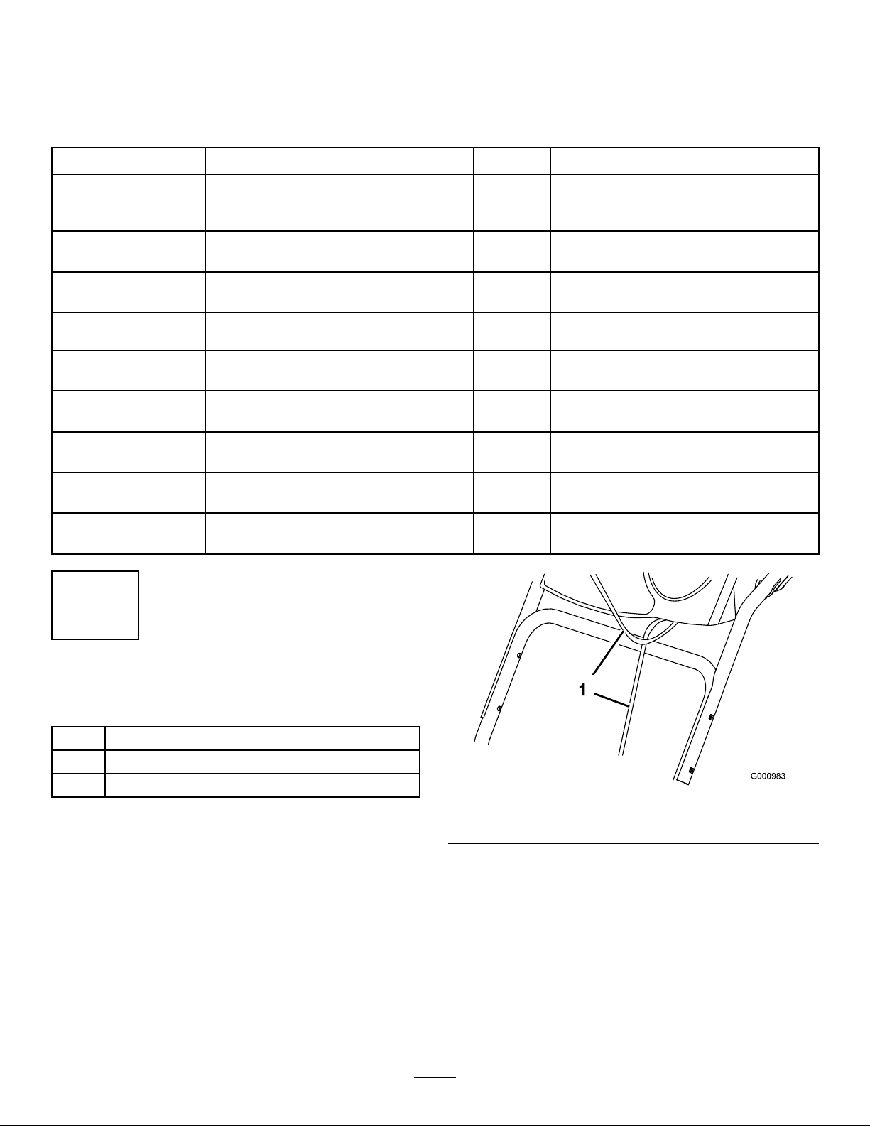
1
InstallingtheUpperHandle
Partsneededforthisprocedure:
4Handlebolts
4
Curvedwashers
4Locknuts
Procedure
Note:Donotremovetherubberbandonthecables
untilyouhaveinstalledtheupperhandle.
1.Liftandrotatetheupperhandleandpositionitover
thelowerhandle(Figure3).
Important:Routethecablesattachedtothe
QuickStickinsidetheupperhandlelegsand
ensurethatthecablesandthewireforthe
headlightarenotpinchedbetweenthehandle
sections.
Figure3
1.Cables
2.Securetheupperhandlewith4handlebolts,
4curvedwashers,and4locknutsfromtheloose
partsbag(Figure4).
7
Page 8
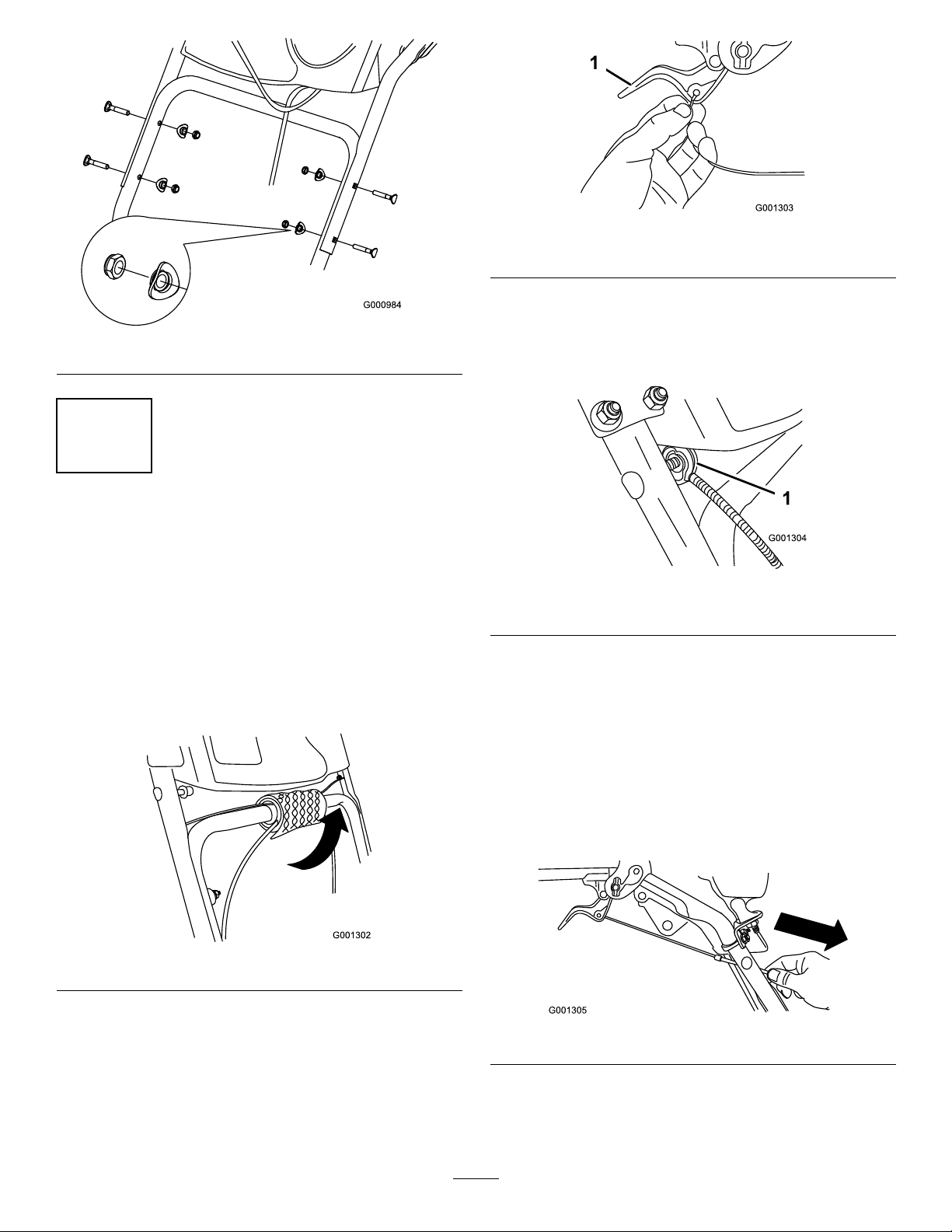
Figure4
2
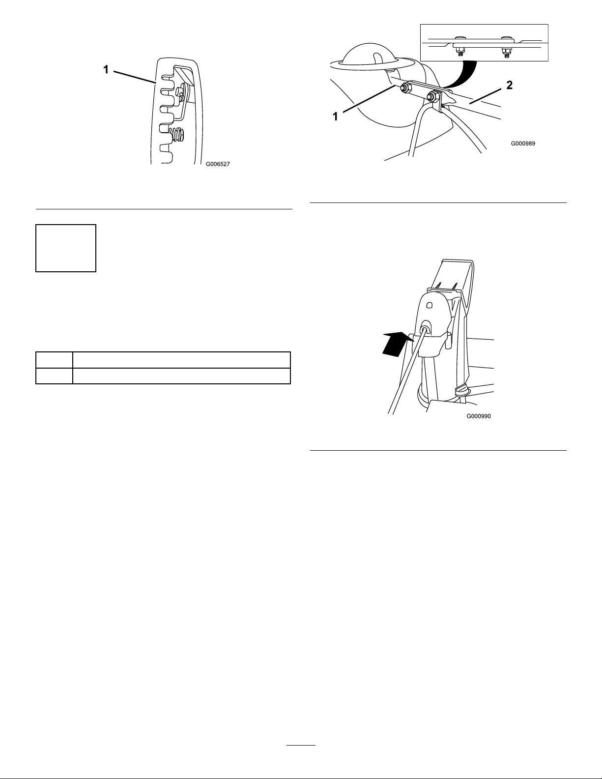
InstallingtheWheelClutch
CableEnds
Figure6
1.Wheelclutchlever
3.Removethenutandwasherfromthehandle,attach
thecableclamponthecabletothehandle,install
thewasherandthenut,andhandtightenthenut
Figure7).
(
NoPartsRequired
Procedure
Models38637and38657only
1.Unwrapthecableendsfromthelowerhandle
Figure5).
(
Figure5
2.Routeeithertheleftorrightcableendoverthelower
handleandinsertthecableendintotheholeinthe
correspondingwheelclutchlever(Figure6).
Figure7
1.Cableclamp(2)
Important:Ensurethatthecurvedsideofthe
cableclampisagainstthehandleandthatthe
cableisroutedbelowtheclampbolt.Thecable
mustbeinastraightlinefromthecableclamp
tothepointwhereitattachestothewheelclutch
lever.
4.Pullthecablejacketdowngentlyuntilthewheel
clutchleverisdownandtheslackisoutofthecable,
thentightenthecableclampnutsecurely(
Figure8
Figure8).
5.Squeezetheleverfully,thencheckthegapbetween
thebottomofthehandleandthewheelclutchlever
end(Figure9).
8
Page 9
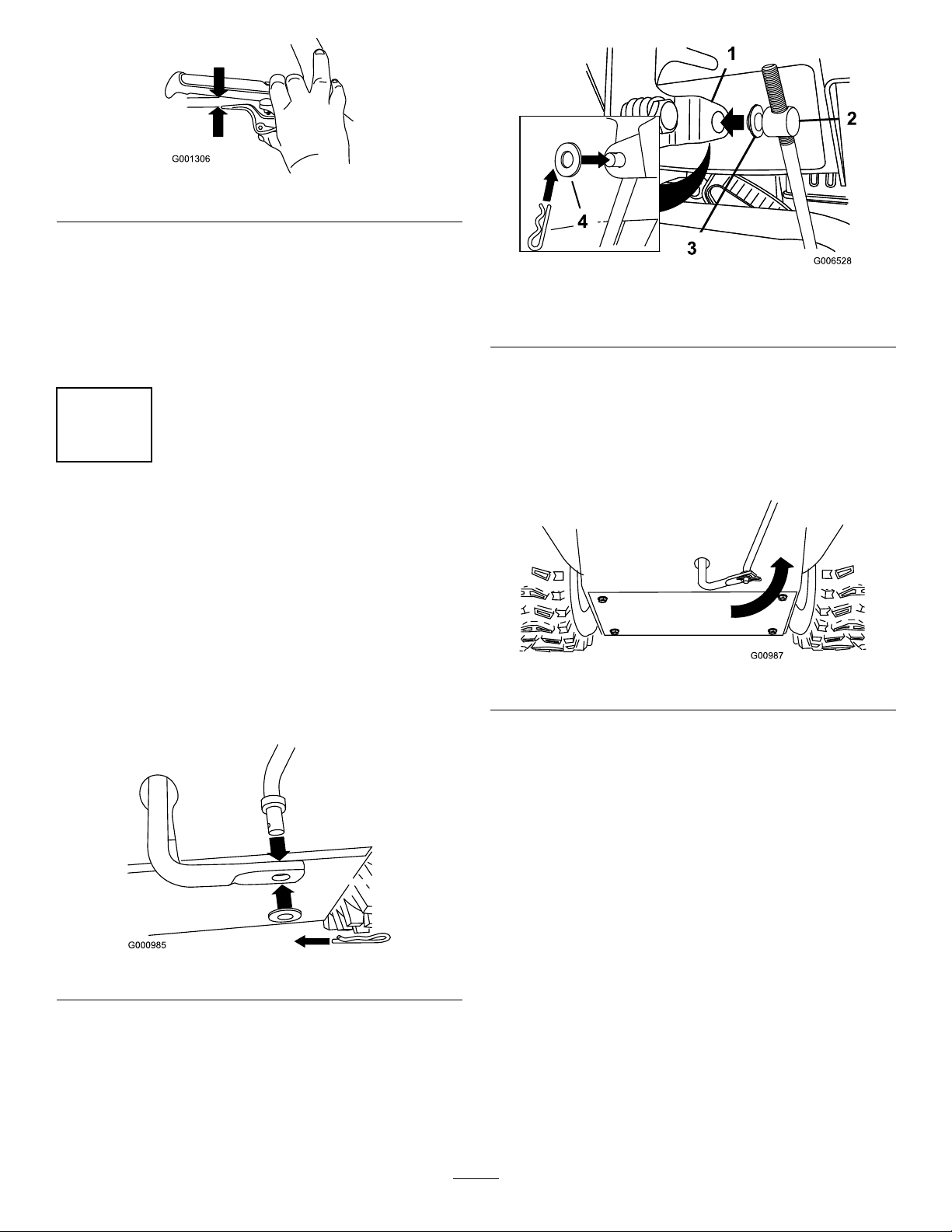
Figure9
Note:Thegapshouldbeapproximatelythe
thicknessofapencil(1/4inchor6mm).Ifitis
greater,loosenthecableclampnut,slidethecable
jacketupslightly,tightenthecableclampnut,and
checkthegapagain.
6.Repeatsteps2through5fortheothercable.
3
InstallingtheTractionControl
Linkage
NoPartsRequired
Procedure
Figure11
1.Speedselectorlever
2.Trunnion
Note:Tomakeinstallationeasier,leavetheat
washeronthetrunnion(
4.ShiftthespeedselectorleverintoPositionR2.
5.Rotatethelowerlinkarmfullyupward
(counterclockwise)(Figure12).
3.Innerwasher
4.Outerwasher
Figure11).
1.Removethehairpincotterandwasherfromthe
lowerendofthespeedcontrolrodandinsertthe
lowerendoftherodintothelowerlinkarmsothat
thebentendofthespeedcontrolrodfacesrearward
Figure10).
(
Figure10
2.Securethelowerendofthespeedcontrolrodwith
thewasherandhairpincotterthatyoupreviously
removed.
Figure12
6.Liftuponthespeedcontrolrodandinsertthe
trunnionintotheholeinthespeedselectorlever
Figure11).
(
Note:Ifthetrunniondoesnottintothehole
whenyouliftuponthespeedcontrolrod,rotatethe
trunnionupwardordownwardonthespeedcontrol
roduntilitts.
7.Securethetrunnionandupperendofthespeed
controlrodwiththeouterwasherandahairpin
cotteryoupreviouslyremoved.
3.Removethehairpincotterandtheouterwasher
fromthetrunnionontheupperendofthespeed
controlrod(
Figure11).
9
Page 10
Note:Foreasierinstallation,lookdownthrough
theopeninginthespeedselector(Figure13).
Figure13
1.Speedselector
4
InstallingtheChuteControl
Rod
Partsneededforthisprocedure:
2
Carriagebolts
2Locknuts
Procedure
1.UnwraptheQuickStickandrotateitsothatitis
uprightandinthecenter.
Figure14
1.Shortrod
4.Insertthefrontendoftherodintotheopeningin
thebackofthechutegearcoveruntilitslidesinto
thechutegear(Figure15).
2.Longchutecontrolrod
Figure15
2.Holdthebluetriggercapdownandpullthelever
fullyrearward.
Note:Thedischargechuteanddeectorshould
faceforward.Iftheydonot,holdthebluetrigger
capdown(butdonotmovetheQuickStick)and
rotatethedischargechuteuntiltheydo.
3.Aligntheattenedbackendofthelongchute
controlrodwiththeattenedfrontendoftheshort
rodthatextendsfromthecontrolpanelsothatthey
nesttogether(
Figure14).
5.Aligntheholesinthenestedendsoftherodsand
insert2carriagebolts(intheloosepartsbag)through
theshortrodfromtheleftsideofthemachine(from
theoperatingposition).
6.Insertthecableclipthatsupportsthedeector
cableontotheforwardcarriagebolt,andsecurethe
carriageboltswithlocknutsfromtheloosepartsbag
Figure16).
(
10
Page 11

Note:Ensurethattheplasticcliponthewire
connectorisonthebottom(Figure17).
2.Secureacabletie(fromtheloosepartsbag)around
thewireandthehandleaboutaninch(2.5cm)below
theU-bolt(
Figure17).
Figure16
1.Cableclip2.Deectorcable
7.HoldthebluetriggercapdownandrotatetheQuick
Stickinacircletoensurethatthechuteanddeector
operatesmoothly.
5
ConnectingtheWiretothe
Headlight
Partsneededforthisprocedure:
1
Cabletie
Procedure
1.Insertthewireconnectoronthelooseendofthe
wirestraightintothebackoftheheadlightuntilitis
securelyinplace(Figure17).
6
FillingtheEnginewithOil
NoPartsRequired
Procedure
Yourmachinecomeswithoilintheenginecrankcase.
Note:Beforestartingtheengine,checktheoillevel
andaddoilifnecessary.
UseautomotivedetergentoilwithanAPIservice
classicationofSF,SG,SH,SJ,SL,orhigher.Referto
yourengineowner’smanual.
UseFigure18belowtoselectthebestoilviscosityfor
theoutdoortemperaturerangeexpected:
1.Plasticcliponwire
connector
2.U-bolt
Figure17
3.Cabletie
1.UsingSAE30atoutdoor
EngineOilCapacities
11
temperaturesbelow40°F
(4°C)willresultinhard
starting.
Figure18
2.Using10W-30atoutdoor
temperaturesabove
80°F(27°C)mayresultin
increasedoilconsumption;
therefore,checktheoil
levelmorefrequentlyin
thesecircumstances.
Page 12

EngineOilCapacities(cont'd.)
Model
38597
38629
38637
38639
38657
1.Removethedipstickandslowlypouroilintothe
oillltubetoraisetheoilleveltotheFullmarkon
thedipstick.Donotoverll(Figure19).Referto
CheckingtheEngineOilLevelinMaintenance.
EngineOilCapacity
18to20oz.(0.53to0.59l)
26to28oz.(0.77to0.83l)
8
CheckingtheSkids
NoPartsRequired
Procedure
RefertoCheckingandAdjustingtheSkidsin
Maintenance.
9
CheckingtheTractionDrive
Operation
NoPartsRequired
Procedure
Figure19
2.Installthedipsticksecurely.
Note:Donotspilloilaroundtheoillltube;oil
couldleakontotractionpartsandcausethetraction
toslip.
7
CheckingtheTirePressure
NoPartsRequired
Procedure
CAUTION
Ifthetractiondriveisnotproperlyadjusted,the
machinemaymoveinthedirectionoppositeof
whatyouintended,causinginjuryand/orproperty
damage.
Carefullycheckthetractiondriveandadjustit
properly,ifnecessary.
1.Starttheengine;refertoStartingtheEngine.
2.MovethespeedselectortoPositionR1;referto
OperatingtheSpeedSelector.
3.Squeezethelefthand(traction)levertothehand-grip
Figure20).
(
Thetiresareoverinatedatthefactoryforshipping.
Reducethepressureequallyinbothtirestobetween17
and20psi(116and137kPa).
Figure20
Themachineshouldmoverearward.Ifthemachine
doesnotmoveormovesforward,completethe
following:
12
Page 13

A.Releasethetractionleverandstoptheengine.
B.Disconnectthetrunnionfromthespeedselector
lever(Figure11).
C.Turnthetrunniondownward(clockwise)onthe
speedcontrolrod(
Figure11).
D.Connectthetrunniontothespeedselectorlever
(Figure11).
4.Releasethetractionlever.
5.MovethespeedselectortothePosition1;referto
OperatingtheSpeedSelector.
6.Squeezethelefthand(traction)levertothehand-grip
Figure20).
(
Themachineshouldmoveforward.Ifthemachine
doesnotmoveormovesrearward,completethe
following:
A.Releasethetractionleverandstoptheengine.
ProductOverview
B.Disconnectthetrunnionfromthespeedselector
Figure11).
lever(
C.Turnthetrunnionupward(counterclockwise)on
thespeedcontrolrod(
Figure11).
D.Connectthetrunniontothespeedselectorlever
(Figure11).
7.Ifyoumadeanyadjustments,repeatthisprocedure
untilnoadjustmentsarerequired.
Important:Ifthemachinemoveswhenthetraction
leverisinthereleasedposition,checkthetraction
cable(refertoCheckingandAdjustingtheTraction
Cable)ortakethemachinetoanAuthorizedService
Dealerforservice.
Figure21
1.Hand-grip(2)10.Scraper
2.Auger/impellerlever
3.Speedselectorlever12.Skid(2)
4.QuickStick™discharge
chutecontrol
5.Tractionlever
6.Fueltankcap
7.Engineoillltube/dipstick16.Headlight(models38637,
8.Chutedeector17.Wheelclutchlever(2)
9.Dischargechute
11.Auger
13.Electricstarterbutton(all
modelsexcept38597)
14.Electricstarterplug(all
modelsexcept38597)
15.Snowcleanouttool
38639,and38657only)
(models38637and38657
only)
13
1.Choke
2.Ignitionswitch
3.Fuelshutoffvalve
4.Throttle
Figure22
5.Recoilstarter
6.Oildrainplug
7.Primer
Page 14

Figure23
1.Snowcleanouttool(attachedtothehandle)
Operation
Note:Determinetheleftandrightsidesofthemachine
fromthenormaloperatingposition.
FillingtheFuelTank
DANGER
Gasolineisextremelyammableandexplosive.A
reorexplosionfromgasolinecanburnyouand
others.
•Topreventastaticchargefromignitingthe
gasoline,placethecontainerand/ormachine
onthegroundbeforelling,notinavehicleor
onanobject.
•Fillthetankoutdoorswhentheengineiscold.
Wipeupspills.
•Donothandlegasolinewhensmokingoraround
anopenameorsparks.
•Storegasolineinanapprovedfuelcontainer,out
ofthereachofchildren.
Fillthefueltankwithfreshunleadedregulargasoline
fromamajorname-brandservicestation(Figure24).
Important:T oreducestartingproblems,add
fuelstabilizertothefuelallseason,mixingitwith
gasolinelessthan30daysold.
the gasoline.
Do not add oil to
Figure24
1.1-1/2inch(3.8cm)
StartingtheEngine
1.Checktheengineoillevel.RefertoCheckingthe
EngineOilLevelinMaintenance.
2.Turnthefuelshutoffvalve1/4turncounterclockwise
toopenit(Figure25).
Figure25
3.Inserttheignitionkey(Figure26).
14
Page 15

Figure26
1.Ignitionkey
4.Firmlypushintheprimerwithyourthumb2times
(15°For-9°Corabove)or4times(below15°For
-9°C),holdingtheprimerinforasecondbefore
releasingiteachtime(Figure27).
Figure28
6.MovethethrottletotheFastposition(Figure29).
Figure29
7.Startthemachinepullingtherecoilstarteror
pressingtheelectric-starterbutton(allmodelsexcept
38597)(
Figure30).
Figure27
5.RotatethechoketotheChokeposition(Figure28).
1.Electric-starterbutton(all
modelsexcept38597)
2.Electricstarterplug(all
modelsexcept38597)
Note:T ousetheelectricstarter,connectapower
cordtotheelectricstarterplugrstandthentoa
poweroutlet(allmodelsexcept38597).
15
Figure30
3.Recoilstarter
Page 16

Important:T opreventdamagingtheelectric
starter,runitinshortcycles(5seconds
maximum,thenwaitoneminutebeforetrying
tostartitagain).Iftheenginestilldoesnot
start,takethemachinetoanAuthorizedService
Dealerforservice(allmodelsexcept38597).
8.Disconnectthepowercordfromthepoweroutlet
rstandthenfromthemachine(allmodelsexcept
38597).
9.Allowtheenginetowarmupforseveralminutes,
movethechoketowardtheRunposition.Wait
fortheenginetorunsmoothlybeforeeachchoke
adjustment.
CAUTION
Ifyouleavethemachinepluggedintoapower
outlet,someonecaninadvertentlystartthe
machineandinjurepeopleordamageproperty.
Unplugthepowercordwheneveryouarenot
startingthemachine.
StoppingtheEngine
1.MovethethrottletotheSlowposition,andthento
theStopposition(Figure31).
Figure32
5.Pulltherecoilstarter3or4times.Thishelpsprevent
therecoilstarterfromfreezingup.
OperatingtheTractionDrive
CAUTION
Ifthetractiondriveisnotproperlyadjusted,the
machinemaymoveinthedirectionoppositeof
whatyouintended,causinginjuryand/orproperty
damage.
Carefullycheckthetractiondriveandadjust
itproperly,ifnecessary;refertoCheckingthe
TractionDriveOperationinSetupformore
information.
Figure31
2.Waitforallmovingpartstostopbeforeleavingthe
operatingposition.
3.Removetheignitionkey.
4.Closethefuelshutoffvalvebyrotatingitclockwise
(Figure32).
Important:Ifthemachinemoveswhenthetraction
leverisinthereleasedposition,checkthetraction
cable(refertoCheckingandAdjustingtheTraction
Cable)ortakethemachinetoanAuthorizedService
Dealerforservice.
1.Toengagethetractiondrive,squeezethelefthand
(traction)levertothehand-grip(
Figure33
2.Tostopthetractiondrive,releasethetractionlever.
Figure33).
16
Page 17

UsingtheWheelClutchLevers
OperatingtheSpeedSelector
Models38637and38657only
Thewheelclutchleversallowyoutomomentarily
disengagethedrivetooneorbothwheelswiththe
tractiondriveleverstillengaged.Thisenablesyouto
turnandmaneuverthemachineeasily.
Note:Holdingdownthetractionleveragainstthe
handleengagesthetractiondrivetobothwheels.
Toturnthemachinetotheright,liftupontheright
wheelclutchleverandsqueezeittowardthehandle
Figure34).
(
Figure34
Note:Thisdisengagesthedrivetotherightwheel
whiletheleftwheelcontinuesdriving,andthemachine
turnstotheright.
Thespeedselectorhas6forwardand2reversegears.
Tochangespeeds,releasethetractionleverandshiftthe
speedselectorlevertothedesiredposition(Figure36).
Theleverlocksinanotchateachspeedselection.
Figure36
OperatingtheAuger/Impeller
Drive
1.Toengagetheauger/impellerdrive,squeezethe
righthand(auger/impeller)levertothehandgrip
(Figure37).
Note:Similarly,squeezingtheleftwheelclutchlever
turnsthemachinetotheleft.
Whenyoucompletetheturn,releasethewheelclutch
lever,andthedrivere-engagesbothwheels(
Figure35
Momentarilysqueezingandreleasingtheleftorright
wheelclutchleveralsoallowsforsteeringadjustments
tokeepthemachinegoinginastraightline,especially
indeepsnow .
Squeezingbothwheelclutchleverssimultaneously
disengagesthedrivetobothwheels.Thisenablesyouto
manuallymovethemachinebackwardwithoutstopping
toshiftitintoareversegear.Italsoallowsyouto
maneuverandtransportthemachinemoreeasilywhen
theengineisnotrunning.
Figure35).
Figure37
2.Tostoptheaugerandimpeller,releasetheright
handlever.
Important:Whenyouengageboththe
auger/impellerleverandthetractionlever,the
tractionleverlockstheauger/impellerlever
down,freeingyourrighthand.Toreleaseboth
levers,simplyreleasethelefthand(traction)
lever.
3.Iftheaugerandimpellercontinuetorotatewhen
youreleasetheauger/impellerlever,donotoperate
themachine.Checktheauger/impellercable(refer
toCheckingandAdjustingtheAuger/Impeller
Cable)andadjustitifnecessary.Otherwise,takethe
machinetoanAuthorizedDealerforservice.
17
Page 18

WARNING
Iftheaugerandimpellercontinuetorotate
whenyoureleasetheauger/impellerlever,you
couldseriouslyinjureyourselforothers.
Donotoperatethemachine.Takeittoan
AuthorizedServiceDealerforservice.
OperatingtheQuickStick
HoldthebluetriggercapdowntousetheQuickStick
tomovethedischargechuteandthechutedeector.
Releasethetriggercaptolockthedischargechuteand
chutedeectorintoposition(
Figure38).
®
•Ifthechutedoesnotmove,refertoAdjustingthe
DischargeChuteLatch.
•Ifthechutedoesnotturnasfartotheleftasitdoes
totheright,ensurethatthecableisroutedtothe
insideofthehandles.RefertoInstallingtheUpper
Handle.
•Ifthechutedoesnotlockintoplacewhenyourelease
thetriggercap,refertoAdjustingtheDischarge
ChuteLatch.
MovingtheChuteDeector
HoldthebluetriggercapdownandmovetheQuick
Stickforwardtolowerthechutedeector;moveit
rearwardtoraisethechutedeector(Figure40).
Figure38
MovingtheDischargeChute
HoldthebluetriggercapdownandmovetheQuick
Sticktothelefttomovethedischargechutetotheleft;
movetheQuickSticktotherighttomovethedischarge
chutetotheright(Figure39).
Figure39
Figure40
UncloggingtheDischarge
Chute
Iftheauger/impellerisrunningbutthereisnosnow
comingoutofthedischargechute,thedischargechute
maybeclogged.
•Tounclogthedischargechute,stayintheoperating
positionandreleasethelefthand(traction)lever.
Whilerunningtheauger/impeller,pushdownon
thehandlestoraisethefrontofthemachineafew
inches(centimeters)offthepavement.Thenliftthe
handlesquicklytobumpthefrontofthemachineon
thepavement.Repeatifnecessaryuntilastreamof
snowcomesoutthedischargechute.
•Ifyoucannotunclogthedischargechutebybumping
thefrontofthemachine,stoptheengine,waitfor
allmovingpartstostop,anduseastick;never
useyourhand.
Important:Uncloggingthedischargechute
bybumpingthefrontofthemachineonthe
18
Page 19

pavementmaycausetheskidstomove.Adjust
theskidsandtightentheskidboltssecurely.
PreventingFreeze-up
WARNING
Therotorbladescanthrowstones,toys,andother
foreignobjectsandcauseseriouspersonalinjuryto
theoperatorortobystanders.
•Insnowyandcoldconditions,somecontrolsand
movingpartsmayfreeze.Donotuseexcessive
forcewhentryingtooperatefrozencontrols.If
youhavedifcultyoperatinganycontrolorpart,
starttheengineandletitrunforafewminutes.
•Afterusingthemachine,lettheenginerunfora
fewminutestopreventmovingpartsfromfreezing.
Engagetheauger/impellertoclearanyremaining
snowfrominsidethehousing.RotatetheQuick
Sticktopreventitfromfreezing.Stoptheengine,
waitforallmovingpartstostop,andremoveallice
andsnowfromthemachine.
•Withtheengineoff,pulltherecoilstarterhandle
severaltimesandpushtheelectric-starterbutton
once(allmodelsexcept38597)topreventtherecoil
andelectricstartersfromfreezingup.
OperatingTips
DANGER
•Keeptheareatobeclearedfreeofallobjects
thattherotorbladescouldpickupandthrow.
•Keepallchildrenandpetsawayfromthearea
ofoperation.
•AlwayssetthethrottletotheFastpositionwhen
throwingsnow.
•Iftheengineslowsdownunderaloadorthewheels
slip,shiftthemachineintoalowergear.
•Ifthefrontofthemachineridesup,shiftthe
machineintoalowergear.Ifthefrontcontinuesto
rideup,liftuponthehandles.
•Thepivotingscraperonthemachineisnot
recommendedforuseongravelsurfaces.But
ifyoumustusethemachineonagravelsurface,
adjusttheskidsfurtherdowntopreventthepivoting
scraperfrompickinguprocks.
Whenthemachineisinoperation,theimpellerand
augercanrotateandcutofforinjurehandsandfeet.
•Beforeadjusting,cleaning,inspecting,
troubleshooting,orrepairingthemachine,stop
theengineandwaitforallmovingpartstostop.
Disconnectthewirefromthesparkplugand
keepitawayfromtheplugtopreventsomeone
fromaccidentallystartingtheengine.
•Removeanobstructionfromthedischarge
chute;refertoUncloggingtheDischargeChute.
Ifnecessary,useastick,notyourhands,to
removeanobstructionfromthedischargechute.
•Staybehindthehandlesandawayfromthe
dischargeopeningwhileoperatingthemachine.
•Keepface,hands,feet,andanyotherpartof
yourbodyorclothingawayfromconcealed,
moving,orrotatingparts.
19
Page 20

Maintenance
Note:Determinetheleftandrightsidesofthemachinefromthenormaloperatingposition.
RecommendedMaintenanceSchedule(s)
MaintenanceService
Interval
Aftertherst2hours
Aftertherst5hours
Beforeeachuseordaily
Every50hours
Yearly
Yearlyorbeforestorage
MaintenanceProcedure
•Inspectthetractioncableandadjustitifnecessary.
•Changetheengineoil.
•Checktheengineoillevelandaddoilifnecessary.
•Changetheengineoil.Changetheengineoilevery25operatinghourswhen
operatingtheengineunderaheavyload.
•Checktheskidsandthescraperandadjustthemifnecessary.
•Checktheskidsandadjustthemifnecessary.
•Inspectthetractioncableandadjustorreplaceitifnecessary.
•Checktheaugergearboxoilandaddoilifnecessary.
•Checktheairpressureinthetiresandinatethemto17–20psi(116–137kPa).
•Drainthegasolineandruntheenginetodryoutthefueltankandthecarburetorat
theendoftheseason.
•HaveanAuthorizedServiceDealerinspectandreplacethetractiondrivebeltand/or
theauger/impellerdrivebelt,ifnecessary.
Important:Youcanndmoreinformationaboutmaintainingandservicingyourmachineat
www.Toro.com.
Important:Refertoyourengineoperator’smanualforadditionalmaintenanceprocedures.Forengine
adjustments,repairs,orwarrantyservicenotcoveredinthismanual,contactanAuthorizedBriggs
&StrattonServicingDealer.
20
Page 21

PreparingforMaintenance
1.Movethemachinetoalevelsurface.
2.Stoptheengineandwaitforallmovingpartstostop.
3.Disconnectthesparkplugwire.RefertoReplacing
theSparkPlug.
CheckingtheEngineOilLevel
ServiceInterval:Beforeeachuseordaily—Check
theengineoillevelandaddoilif
necessary.
1.Removethedipstick,wipeitclean,thenfullyinstall
thedipstick.
2.Removethedipstickandchecktheoillevel
Figure41).IftheoillevelisbelowtheAddmark
(
onthedipstick,addoil.RefertoFillingtheEngine
withOil.
Figure42
1.1/2inch(1.3cm)
3.Supportthesideplatessothattheyareatleast1/2
inch(1.3cm)abovealevelsurface.
Important:Theaugerbladesmustbe
supportedabovethegroundbytheskids.
4.Ensurethatthescraperis1/8inch(3mm)above
andparalleltoalevelsurface.
Note:Ifthepavementiscracked,rough,oruneven,
adjusttheskidstoraisethescraper.Forgravel
surfaces,adjusttheskidsfurtherdowntoprevent
themachinefrompickinguprocks.
5.Movetheskidsdownuntiltheyareevenwiththe
ground.
6.Firmlytightenthenutsthatsecurebothskidstothe
augersides.
Note:Toquicklyadjusttheskidsiftheyloosen,
supportthescraper1/8inch(3mm)offthe
pavement,thenadjusttheskidsdowntothe
pavement.
Figure41
CheckingandAdjustingthe
SkidsandScraper
ServiceInterval:Yearly—Checktheskidsandthe
scraperandadjustthemifnecessary.
Allmodelsexceptmodel38657
Checktheskidsandthescrapertoensurethattheauger
doesnotcontactthepavedorgravelsurface.Adjustthe
skidsandthescraperasneededtocompensateforwear.
1.Checkthetirepressure.RefertoCheckingtheTire
Pressure.
2.Loosenthenutsthatsecurebothskidstothe
augersidesuntiltheskidsslideupanddowneasily
(Figure42).
Note:Iftheskidsbecomeexcessivelyworn,you
canturnthemoverandsettheunusedsidetoward
thepavement.
CheckingandAdjustingthe
Skids
ServiceInterval:Yearly—Checktheskidsandadjust
themifnecessary.
Model38657only
Checktheskidstoensurethattheaugerdoesnot
contactthepavedorgravelsurface.Adjusttheskidsas
neededtocompensateforwear.
1.Checkthetirepressure.RefertoCheckingtheTire
Pressure.
2.Movethemachinetoalevelsurface.
3.Loosenthenutsthatsecurebothskidstothe
augersidesuntiltheskidsslideupanddowneasily
(
Figure43).
21
Page 22

Figure43
1.Skid
4.Pushdownonthehandlestoallowthepivoting
scrapertomovefullyforward,thensetthefront
ofthemachinedownsothatthefrontedgeofthe
pivotingscrapercontactstheground(Figure44).
CheckingandAdjustingthe
TractionCable
ServiceInterval:Aftertherst2hours—Inspect
thetractioncableandadjustitif
necessary.
Yearly—Inspectthetractioncable
andadjustorreplaceitifnecessary.
Ifthemachinedoesnotdriveintheforwardorreverse
speedsoritdriveswhenyoureleasethetractionlever,
adjustthetractioncable.
Withthetractionleverdisengaged,checkthepininthe
elongatedslotintheleftsideofthemachineabovethe
tire.Thereshouldbeagapof1/32to1/16inch(1to
1.5mm)fromthefrontoftheslottothefrontedgeof
thepin(
Figure45).
Figure44
1.Pivotingscraper
5.Movetheskidsdownuntiltheyareevenwiththe
ground.
Note:Forasmoothsurface,youcansettheskids
slightlyhighertoincreasethescrapingaction,but
settheskidsfarenoughdowntopreventtheauger
bladesfromcontactingtheground.
Note:Thepivotingscraperonthemachineis
notrecommendedforuseongravelsurfaces.
Butifyoumustusethemachineonagravelsurface,
adjusttheskidsfurtherdowntopreventthepivoting
scraperfrompickinguprocks.
6.Firmlytightenthenutsthatsecurebothskidstothe
augersides.
Note:Iftheskidsbecomeexcessivelyworn,you
canturnthemoverandsettheunusedsidetoward
thepavement.
Figure45
1.Pin
Ifthelefthand(traction)cableisnotproperlyadjusted,
dothefollowingsteps:
1.Loosenthejamnut.
2.Loosenortightentheturnbuckletoadjustthepin
untilitisthepropergapfromthefrontedgeofthe
slot.
3.Tightenthejamnut(
Figure46).
1.Jamnut2.Turnbuckle
22
Figure46
Page 23

CheckingtheAugerGearbox
OilLevel
ServiceInterval:Yearly—Checktheaugergearboxoil
andaddoilifnecessary.
1.Movethemachinetoalevelsurface.
2.Cleantheareaaroundthepipeplug(
Figure47
Figure47).
3.Removethepipeplugfromthegearbox.
4.Checktheoillevelinthegearbox.Theoilshouldbe
atthepointofoverowingatthelleropening.
5.Iftheoillevelislow,addGL-5orGL-6,SAE85-95
EPtransmissionoiltothegearboxuntilthepoint
ofoverow.
Note:Donotusesyntheticoil.
1.UsingSAE30atoutdoor
temperaturesbelow40°F
(4°C)willresultinhard
starting.
EngineOilCapacities
Model
38597
38629
38637
38639
38657
Figure48
2.Using10W-30atoutdoor
temperaturesabove
80°F(27°C)mayresultin
increasedoilconsumption;
therefore,checktheoil
levelmorefrequentlyin
thesecircumstances.
EngineOilCapacity
18to20oz.(0.53to0.59l)
26to28oz.(0.77to0.83l)
6.Installthepipepluginthegearbox.
ChangingtheEngineOil
ServiceInterval:Aftertherst5hours—Changethe
engineoil.
Every50hours—Changetheengine
oil.Changetheengineoilevery25
operatinghourswhenoperatingthe
engineunderaheavyload.
Ifpossible,runtheenginejustbeforechangingthe
oilbecausewarmoilowsbetterandcarriesmore
contaminants.
UseautomotivedetergentoilwithanAPIservice
classicationofSF,SG,SH,SJ,SL,orhigher.Referto
yourengineowner’smanual.
Figure48belowtoselectthebestoilviscosityfor
Use
theoutdoortemperaturerangeexpected:
1.Cleantheareaaroundtheoildraincap(Figure49).
Figure49
1.Oildraincap
2.Slideanoildrainpanunderthedrainextensionand
removetheoildraincap.
3.Draintheoil.
Note:Disposeoftheusedoilproperlyatalocal
recyclingcenter.
4.Installtheoildraincap.
5.Fillthecrankcasewithoil.RefertoFillingthe
EngineCrankcasewithOil.
23
Page 24

AdjustingtheDischargeChute
Latch
Ifthedischargechutedoesnotlockintothedesired
positionordoesnotunlocksothatyoucanmoveitto
anotherposition,adjustthedischargechutelatch.
1.Removethefasteneronthegearcover(Figure50),
liftthefrontofthecoverup,andslideitbackand
outoftheway.
Note:Thelatchisspringloadedandwillnaturally
moveintotheteethofthegear(Figure52).
4.Removeanyslackinthecablebypullingthecable
conduitrearward.
5.Tightentheboltonthecableclamp.
6.Installandsecurethegearcover.
ReplacingtheDriveBelts
Iftheauger/impellerdrivebeltorthetractiondrivebelt
becomesworn,oil-soaked,orotherwisedamaged,go
towww.Toro.comforadditionalserviceinformationor
haveanAuthorizedServiceDealerreplacethebelt.
ReplacingtheHeadlightBulb
Figure50
2.Loosentheboltonthecableclamp(Figure51).
Figure51
1.Cableconduit2.Cableclamp
3.Graspthecableconduitandmoveittowardthefront
ofthemachineuntilthedischargechutelatchfully
engagesthegearteeth(Figure51andFigure52).
Models38637,38639,and38657only
UseaGE89216Whalogenlightbulb.Donottouch
thebulbwithyourhandsorallowdirtormoistureto
comeintocontactwiththebulb.
1.Removethewireconnectorfromthebackofthe
headlight(
2.Turnthebaseofthebulbcounterclockwiseuntilit
stops(Figure54).
Figure53).
Figure53
1.Dischargechutelatch
Figure54
3.Removethebulbstraightoutfromthebackofthe
headlight(Figure55).
Figure52
2.Gearteeth
24
Page 25

Figure55
4.Insertanewbulbintothebackoftheheadlight
(Figure56).
Figure56
5.Turnthebaseofthebulbclockwiseuntilitissnug
(Figure57).
Figure57
6.Insertthewireconnectorstraightintothebackof
theheadlightuntilitissecurelyinplace(Figure58).
Storage
WARNING
•Gasolinevaporscanexplode.
•Donotstoregasolinemorethan30days.
•Donotstorethemachineinanenclosurenear
anopename.
•Allowtheenginetocoolbeforestoringit.
PreparingtheMachinefor
Storage
1.Onthelastrefuelingoftheyear,addfuelstabilizer
tofreshfuelasdirectedbytheenginemanufacturer.
2.Runtheenginefor10minutestodistributethe
conditionedfuelthroughthefuelsystem.
3.Loosenthehoseclampthatsecuresthefuellineto
thevalveandslidethefuellineoffthefuelshutoff
valve.
4.Openthefuelshutoffvalveandallowthefuelto
drainoutofthefueltankintoanapprovedfuel
container.
5.Installthefuellineontothefuelshutoffvalveand
secureitwithahoseclamp.
6.Runthemachineuntiltheenginestopsfromrunning
outoffuel.
7.Primetheengineandstartitagain.
8.Allowtheenginetorununtilitstops.Whenyoucan
nolongerstarttheengine,itissufcientlydry.
9.Stoptheengineandallowittocool.
10.Removetheignitionkey.
11.Disconnectthesparkplugwire.
12.Removethesparkplug,add1oz.(30ml)ofoil
throughthesparkplughole,andpullthestarterrope
slowlyseveraltimestodistributeoilthroughoutthe
cylindertopreventcylindercorrosionduringthe
off-season.
13.Looselyinstallthesparkplug.
14.Disposeofanyunusedfuelproperly.Recycleit
accordingtolocalcodes,oruseitinyourautomobile.
Figure58
Note:Donotstorestabilizedfuelformorethan
90days.
15.Cleanthemachinethoroughly .
16.Touchupchippedsurfaceswithpaintavailable
fromanAuthorizedServiceDealer.Sandaffected
areasbeforepainting,andusearustpreventativeto
preventthemetalpartsfromrusting.
25
Page 26

17.Tightenallloosescrews,bolts,andlocknuts.Repair
orreplaceanydamagedparts.
18.Coverthemachineandstoreitinaclean,dryplace
outofthereachofchildren.Allowtheengineto
coolbeforestoringitinanyenclosure.
RemovingtheMachinefrom
Storage
1.Removethesparkplugandspintheenginerapidly
usingthestartertoblowtheexcessoilfromthe
cylinder.
2.Installthesparkplugbyhandandthentorqueitto
15ft-lb(20.4N-m).
3.Connectthesparkplugwire.
4.Performtheannualmaintenanceproceduresasgiven
intheRecommendedMaintenanceSchedule.
26
Page 27

Troubleshooting
Problem
Electricstarterdoesnotturn(electric-start
modelsonly)
Enginedoesnotstartorstartshard
PossibleCauseCorrectiveAction
1.Thepowercordisdisconnectedatthe
outletorthemachine.
2.Thepowercordisworn,corroded,or
damaged.
3.Thepoweroutletisnotenergized.
1.Thekeyisnotintheignitionorisinthe
Stopposition.
2.ThechokeisintheOffpositionandthe
primerhasnotbeenpressed.
3.Thefuelshutoffvalveisnotopen.3.Openthefuelshutoffvalve.
4.ThethrottleisnotintheFastposition.4.MovethethrottletotheFastposition.
5.Thefueltankisemptyorthefuel
systemcontainsstalefuel.
6.Thesparkplugwireislooseor
disconnected.
7.Thesparkplugispitted,fouled,orthe
gapisincorrect.
8.Thefuelventcapisrestricted.
9.Theengineoillevelintheengine
crankcaseistoolowortoohigh.
1.Connectthepowercordtotheoutlet
and/orthemachine.
2.Replacethepowercord.
3.Haveaqualiedelectricianenergize
theoutlet.
1.Insertthekeyintotheignitionandturn
ittotheOnposition.
2.MovethechoketotheOnpositionand
presstheprimer3times.
5.Drainand/orllthefueltankwithfresh
gasoline(notmorethan30daysold).
Iftheproblempersists,contactan
AuthorizedServiceDealer.
6.Connectthewiretothesparkplug.
7.Checkthesparkplugandadjustthe
gapifnecessary .Replacethespark
plugifitispitted,fouled,orcracked.
8.Removetheventrestrictionorreplace
thefuelcap.
9.Addordrainoiltoadjusttheoillevelin
theenginecrankcasetotheFullmark
onthedipstick.
Enginerunsrough
Engineruns,butthemachinedischarges
snowpoorlyornotatall
1.ThechokeisintheOnposition.1.MovethechoketotheOffposition.
2.Thefuelshutoffvalveisnotcompletely
open.
3.Thefueltankisnearlyemptyor
containsstalefuel.
4.Thesparkplugwireisloose.
5.Thesparkplugispitted,fouled,orthe
gapisincorrect.
6.Theengineoillevelintheengine
crankcaseistoolowortoohigh.
1.ThethrottleisnotintheFastposition
whenthrowingsnow .
2.Themachineismovingtoofasttoclear
thesnow.
3.Y ouaretryingtoremovetoomuch
snowperswath.
4.Y ouaretryingtoremoveextremely
heavyorwetsnow.
5.Thedischargechuteisplugged.5.Unclogthedischargechute.
6.Theauger/impellerdrivebeltisloose
orisoffthepulley.
2.Openthefuelshutoffvalve.
3.Drainandllthefueltankwithfresh
gasoline(notmorethan30daysold).
Iftheproblempersists,contactan
AuthorizedServiceDealer.
4.Connectthewiretothesparkplug.
5.Checkthesparkplugandadjustthe
gapifnecessary .Replacethespark
plugifitispitted,fouled,orcracked.
6.Addordrainoiltoadjusttheoillevelin
theenginecrankcasetotheFullmark
onthedipstick.
1.MovethethrottletotheFastposition.
2.Shiftthemachineintoalowergear.
3.Reducetheamountofsnowremoved
perswath.
4.Don’toverloadthemachinewith
extremelyheavyorwetsnow.
6.Installand/oradjusttheauger/impeller
drivebelt;refertowww.Toro.com
forservicinginformationortakethe
machinetoanAuthorizedService
Dealer.
27
Page 28

Problem
7.Theauger/impellerdrivebeltisworn
orbroken.
PossibleCauseCorrectiveAction
7.Replacetheauger/impellerdrivebelt;
refertowww.Toro.comforservicing
informationortakethemachinetoan
AuthorizedServiceDealer.
Dischargechuteeitherdoesnotlockinto
placeordoesnotmove
Themachinedoesnotproperlyclearthe
snowoffthesurface
1.Thedischargechutelatchisnot
properlyadjusted.
1.Theskidsand/orscraperarenot
properlyadjusted.
2.Thepressureinthetiresisnotequal.
1.Adjustthedischargechutelatch.
1.Adjusttheskidsand/orthescraper.
2.Checkandadjustthepressureinone
orbothtires.
28
Page 29

Notes:
29
Page 30

Notes:
30
Page 31

InternationalDistributorList
Distributor:
AtlantisSuveSulamaSisstemleriLt
BalamaPrimaEngineeringEquip.HongKong85221552163
B-RayCorporation
CascoSalesCompany
CeresS.A.CostaRica
CSSCTurfEquipment(pvt)Ltd.SriLanka
CyrilJohnston&Co.
EquiverMexico525553995444
FemcoS.A.Guatemala
G.Y .K.CompanyLtd.
GeomechanikiofAthensGreece
GuandongGoldenStarChina
HakoGroundandGardenSweden
HakoGroundandGarden
HayterLimited(U.K.)
HydroturfInt.CoDubai
HydroturfEgyptLLC
IbeaS.P .A.
IrriamcPortugal351212388260
IrrigationProductsInt’lPvtLtd.India862283960789
JeanHeybroekb.v.Netherlands3130639461 1
Lely(U.K.)Limited
MaquiverS.A.Colombia
MaruyamaMfg.Co.Inc.
MetraKft
Mountelda.s.CzechRepublic
MunditolS.A.
OslingerTurfEquipmentSA
OyHakoGroundandGardenAb
ParklandProductsLtd.NewZealand6433493760
Prochaska&Cie
RTCohen2004Ltd.
Riversa
RothMotorgerateGmBh&Co.Germany
ScSvendCarlsenA/S
SolvertS.A.S.
SpyprosStavrinidesLimitedCyprus
SurgeSystemsIndiaLimited
T-MarktLogisticsLtd.Hungary3626525500
ToroAustraliaAustralia61395807355
ToroEuropeBVBABelgium3214562960
Country:
Turkey902163448674
Korea82325512076
PuertoRico7877888383
NorthernIreland442890813121
Japan81726325861
Norway4722907760
UnitedKingdom441279723444
UnitedArabEmirates97143479479
Egypt2025194308
Italy390331853611
UnitedKingdom441480226800
Japan81332522285
Hungary3613263880
Argentina541148219999
Ecuador59342396970
Finland35898700733
Austria4312785100
Israel97298617979
Spain
Denmark4566109200
France33130817700
India911292299901
PhoneNumber:
5062391138
941 12746100
5024423277
30109350054
862087651338
4635100000
5712364079
420255704220
34952837500
4971442050
35722434131
374-0269RevA
Page 32

TheToroWarranty
ConditionsandProductsCovered
TheToro®Companyanditsafliate,ToroWarrantyCompany,pursuantto
anagreementbetweenthem,jointlypromisetorepairtheT oroProduct
listedbelowifusedforresidentialpurposes*ifdefectiveinmaterialsor
workmanship.
Thefollowingtimeperiodsapplyfromthedateofpurchase:
ProductsWarrantyPeriod
WalkPowerMowers2yearlimitedwarranty
RearEngineRiders2yearlimitedwarranty
Lawn&GardenTractors
ElectricHandHeldProducts2yearlimitedwarranty
Snowthrowers
ConsumerZeroTurn
*OriginalPurchasermeansthepersonwhooriginallypurchasedtheToro
Product
*Residentialpurposesmeansuseoftheproductonthesamelotasyour
home.Useatmorethanonelocation,orinstitutionalorrentaluse,is
consideredcommercialuse,andthecommercialusewarrantywould
apply.
2yearlimitedwarranty
2yearlimitedwarranty
2yearlimitedwarranty
LimitedWarrantyforCommercialUse
ToroConsumerProductsandattachmentsusedforcommercial,
institutional,orrentaluse,arewarrantedagainstdefectsinmaterials
orworkmanshipforthefollowingtimeperiodsfromthedateoforiginal
purchase:
ProductsWarrantyPeriod
WalkPowerMowers90daywarranty
RearEngineRiders90daywarranty
Lawn&GardenTractors
ElectricHandHeldProducts90daywarranty
Snowthrowers
ConsumerZeroTurn
90daywarranty
90daywarranty
45daywarranty
InstructionsforObtainingWarrantyService
IfyouthinkthatyourT oroProductcontainsadefectinmaterialsor
workmanship,followthisprocedure:
1.Contactyoursellertoarrangeserviceoftheproduct.Ifforanyreason
itisimpossibleforyoutocontactyourseller,youmaycontactany
ToroAuthorizedDistributortoarrangeservice.
2.Bringtheproductandyourproofofpurchase(salesreceipt)tothe
ServiceDealer.IfforanyreasonyouaredissatisedwiththeService
Dealer’sanalysisorwiththeassistanceprovided,contactusat:
CustomerCareDepartment,ConsumerDivision
TheT oroCompany
811 1LyndaleAvenueSouth
Bloomington,MN55420-1196
Manager:TechnicalProductSupport:001–952–887–8248
SeeattachedDistributorList
OwnerResponsibilities
YoumustmaintainyourT oroProductbyfollowingthemaintenance
proceduresdescribedintheOperator’sManual.Suchroutine
maintenance,whetherperformedbyadealerorbyyou,isatyourexpense.
ItemsandConditionsNotCovered
Thisexpresswarrantydoesnotcoverthefollowing:
•Costofregularmaintenanceserviceorwearparts,suchasrotor
blades(paddles),scraperblades,belts,fuel,lubricants,oilchanges,
sparkplugs,cable/linkageorbrakeadjustments
•Anyproductorpartwhichhasbeenalteredormisusedandrequires
replacementorrepairduetoaccidentsorlackofpropermaintenance
•Repairsnecessaryduetofailuretousefreshfuel(lessthanone
monthold),orfailuretoproperlypreparetheunitpriortoanyperiod
ofnon-useoveronemonth
•Engineandtransmission.Thesearecoveredbytheappropriate
manufacturer’sguaranteeswithseparatetermsandconditions
Allrepairscoveredbythesewarrantiesmustbeperformedbyan
AuthorizedToroServiceDealerusingToroapprovedreplacementparts.
GeneralConditions
Thepurchaseriscoveredbythenationallawsofeachcountry.Therights
towhichthepurchaserisentitledwiththesupportoftheselawsarenot
restrictedbythiswarranty .
374-0268RevA
 Loading...