

Page 1
Power Max™ 6000 Snowthrower
Model No. 38595 —Serial No. 270000001 and Up
Form No. 3355-483 Rev B
Operator's Manual
Introduction
R ead this infor mation carefully to lear n ho w to operate and
maintain y our product properly and to a v oid injur y and
product damag e . Y ou are responsible for operating the
product properly and safely .
Y ou ma y contact T oro directly at www .T oro .com for
product and accessor y infor mation, help finding a dealer ,
or to register y our product.
W henev er y ou need ser vice , g en uine T oro par ts , or
additional infor mation, contact an A uthorized Ser vice
Dealer or T oro Customer Ser vice and ha v e the model and
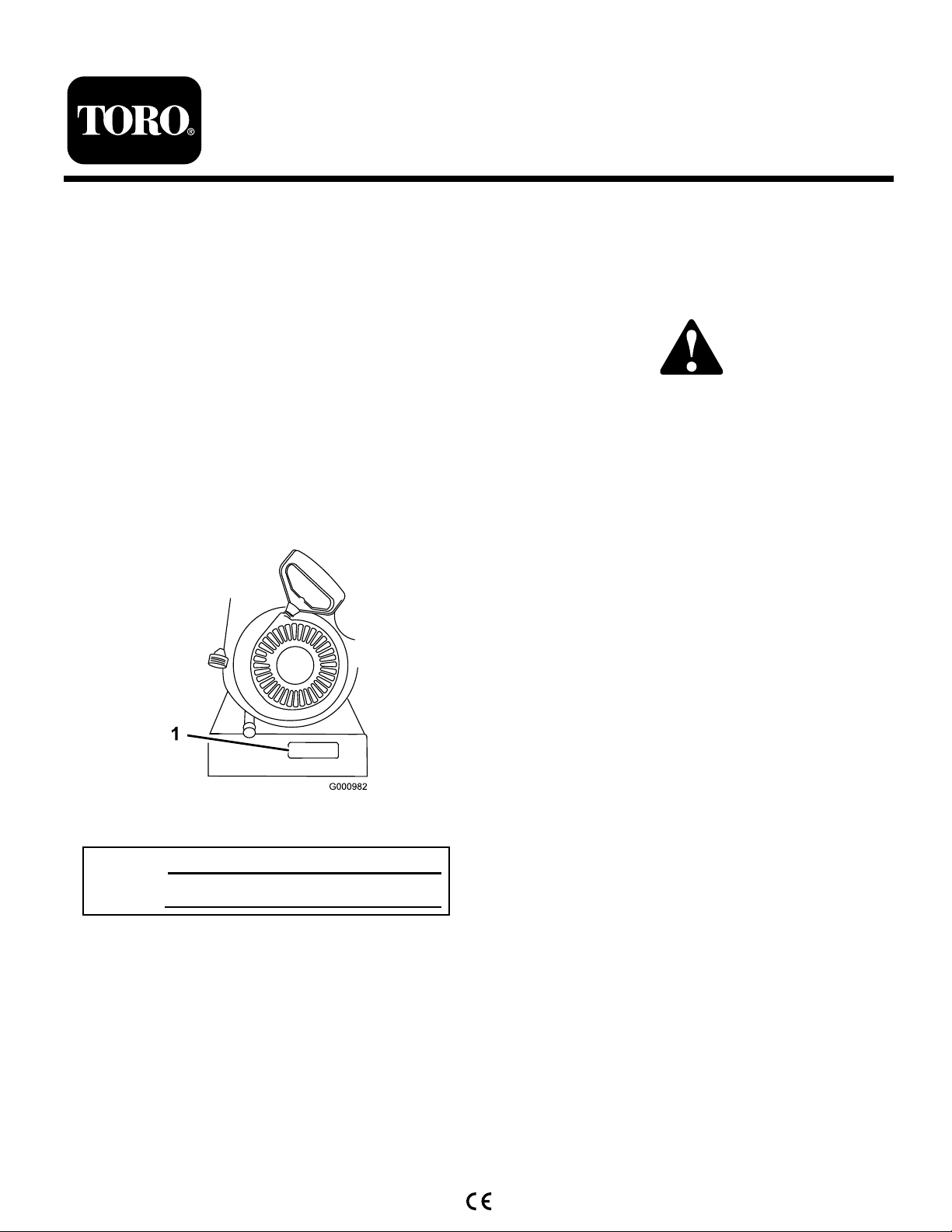
serial n umbers of y our product ready . Figure 1 identifies the
location of the model and serial n umbers on the product.
W rite the n umbers in the space pro vided.
T his man ual identifies potential hazards and has safety
messag es identified b y the safety aler t symbol ( Figure 2 ),
whic h signals a hazard that ma y cause serious injur y or
death if y ou do not follo w the recommended precautions .
Figure 2
1. Safety alert symbol
T his man ual uses 2 w ords to highlight infor mation.
Impor tant calls attention to special mec hanical infor mation
and Note emphasizes g eneral infor mation w or th y of special
attention.
R eplacement Engine Owner’ s Man uals may be order ed
thr ough the engine man uf actur er .
Figure 1
1. Model and serial number location
Model No.
Serial No.
© 2006—The Toro® Company
8111 Lyndale Avenue South
Bloomington, MN 55420
Register at www.Toro.com. Original Instructions (EN)
Printed in the USA
All Rights Reserved
Page 2
Safety
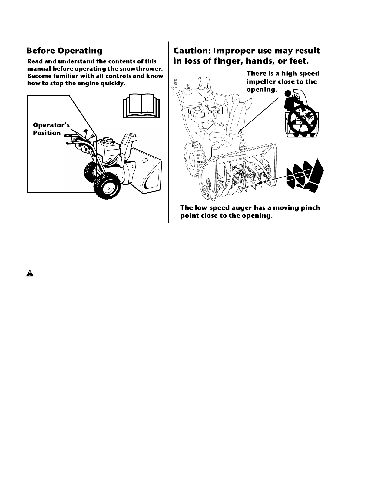
Bef or e Ope r ating
Ca u ti on : Im p ro p er u se ma y r esu lt
in loss of fin g er , h a n d s, o r fe et.
Re a d a nd unders t an d t he cont e n t s o f t hi s
manual b efo re oper atin g th e sn owt hr o w er.
Becom e fam iliar wi t h a ll c o n tr o ls a n d kno w
ho w t o st op t h e eng ine q ui ckly.
Th ere is a h ig h -sp eed
im pe ller close to t h e
o p en in g.
Th e lo w-sp e ed a ug er h a s a m ovin g p in ch
po in t close t o t h e o pe n in g.
Oper at or’s
Posit ion
T his sno wthr o w er meets or ex ceeds the ISO standard
8437 in ef fect at the time of pr oduction.
R ead and under stand the contents of this man ual
bef or e the engine is ev er star ted.
T his is the safety aler t symbol. It is used to aler t y ou
to potential per sonal injur y hazards. Obey all safety
messa ges that f ollo w this symbol to a v oid possible
injur y or death.
Impr oper l y using or maintaining this sno wthr o w er
could r esult in injur y or death. T o r educe this potential,
compl y with the f ollo wing safety instr uctions.
Training
• R ead the operating and ser vice instr uction man ual
carefully . Be thoroughly familiar with the controls and
the proper use of the equipment. Kno w ho w to stop
the unit and diseng ag e the controls quic kly .
• Nev er allo w c hildren to operate the equipment. Nev er
allo w adults to operate the equipment without proper
instr uction.
• K ee p the area of operation clear of all persons ,
par ticularly small c hildren, and pets .
• Ex ercise caution to a v oid slipping or falling, especially
when operating in rev erse .
Preparation
• T horoughly inspect the area where the equipment is to
be used and remo v e all door mats , sleds , boards , wires ,
and other foreign objects .
• Diseng ag e all clutc hes and shift into neutral before
star ting the engine .
• Do not operate the equipment without w earing
adequate winter g ar ments . W ear footw ear whic h will
impro v e footing on slipper y surfaces .
• Handle fuel with care; it is highly flammable .
– Use an appro v ed fuel container .
– Nev er add fuel to a r unning or hot engine .
– Fill fuel tank outdoors with extreme care . Nev er fill
fuel tank indoors .
– R e place g asoline caps securely and wipe up spilled
fuel.
• Adjust the collector housing height to clear g ra v el or
cr ushed roc k surface .
• Nev er attempt to mak e any adjustments while the engine
is r unning (ex ce pt where specifically recommended b y
man ufacturer).
• Let engine and mac hine adjust to outdoor temperatures
before star ting to clear sno w .
• T he operation of any po w ered mac hine can result in
foreign objects being thro wn into the eyes . Alw a ys w ear
2
Page 3

safety glasses or eye shields during operation or while
perfor ming an adjustment or re pair .
Operation
• Do not put hands or feet near or under rotating par ts .
K ee p clear of the disc harg e opening at all times .
• Ex ercise extreme caution when operating on or crossing
g ra v el dri v es , w alks , or roads . Sta y aler t for hidden
hazards or traffic .
• After striking a foreign object, stop the engine , remo v e
the wire from the spark-plug, thoroughly inspect the
sno w thro w er for any damag e , and re pair the damag e
before restar ting and operating the sno w thro w er .
• If the unit should star t to vibrate abnor mally , stop the
engine and c hec k immediately for the cause . Vibration
is g enerally a w ar ning of trouble .
• Stop the engine whenev er y ou lea v e the operating
position, before unclog ging the collector/impeller
housing or disc harg e guide , and when making any
re pairs , adjustments , or inspections .
• W hen cleaning, re pairing, or inspecting, mak e cer tain
the collector/impeller and all mo ving par ts ha v e
stopped. Disconnect the spark-plug wire , and k ee p the
wire a w a y from the plug to prev ent accidental star ting .
• Do not r un the engine indoors , ex ce pt when star ting
it and for mo ving the sno w thro w er in or out of the
building . Open the outside doors; exhaust fumes are
dang erous .
• Do not clear sno w across the face of slopes . Ex ercise
extreme caution when c hanging direction on slopes . Do
not attempt to clear stee p slopes .
• Nev er operate the sno w thro w er without proper guards ,
plates , or other safety protecti v e devices in place .
• Nev er operate the sno w thro w er near glass enclosures ,
automobiles , windo w w ells , drop-offs , etc . without
proper adjustment of the sno w disc harg e angle . K ee p
c hildren and pets a w a y .
• Do not o v erload the mac hine capacity b y attempting to
clear sno w at too fast a rate .
• Nev er operate the mac hine at high transpor t speeds on
slipper y surfaces . Use care when rev ersing .
• Nev er direct disc harg e at b ystanders or allo w any one
in front of the unit.
• Diseng ag e po w er to the collector/impeller when sno w
thro w er is transpor ted or not in use .
• Use only attac hments and accessories appro v ed b y the
man ufacturer of sno w thro w er (suc h as wheel w eights ,
counterw eights , cabs , etc .).
• Nev er operate the sno w thro w er without g ood visibility
or light. Alw a ys be sure of y our footing, and k ee p a fir m
hold on the handles . W alk; nev er r un.
• Nev er operate the sno w thro w er without g ood visibility
or light.
• T ak e all possible precautions when lea ving the mac hine
unattended. Shift into neutral, set the parking brak e ,
stop the engine and remo v e the k ey .
Maintenance and Storage
• Chec k all fasteners at frequent inter v als for proper
tightness to be sure the equipment is in safe w orking
condition.
• Nev er store the mac hine with fuel in the fuel tank inside
a building where ignition sources are present suc h as
hot w ater and space heaters , clothes dr yers , etc . Allo w
the engine to cool before storing in any enclosure .
• Alw a ys refer to o wner’ s guide instr uctions for impor tant
details if the sno w thro w er is to be stored for an
extended period.
• Maintain or re place safety and instr uctions labels , as
necessar y .
• R un the mac hine a few min utes after thro wing sno w to
prev ent freeze-up of the collector/impeller .
Toro Snowthrower Safety
T he follo wing list contains safety infor mation specific to
T oro products or other safety infor mation that y ou m ust
kno w .
• R otating r otor blades can injur e finger s or hands.
Sta y behind the handles and a w a y from the disc harg e
opening while operating the sno wthro w er . K eep y our
f ace, hands, feet, and an y other par t of y our body or
clothing a w ay fr om mo ving or r otating par ts.
• Before adjusting, cleaning, re pairing, and inspecting
the sno wthro w er , and before unclog ging the disc harg e
c hute , stop the engine, r emo v e the k ey , and w ait f or
all mo ving par ts to stop .
• Use the sno w cleanout tool, not y our hands , to remo v e
obstr uctions from the disc harg e c hute .
• Bef or e lea ving the operating position, stop the engine ,
remo v e the k ey , and w ait for all mo ving par ts to stop .
• Do not w ear loose-fitting clothing that could g et caught
in mo ving par ts .
• If a shield, safety device , or decal is damag ed, illegible ,
or lost, re pair or re place it before beginning operation.
Also , tighten any loose fasteners .
• Do not smok e while handling g asoline .
• Do not use the sno wthro w er on a roof .
• Do not touc h the engine while it is r unning or soon
after it has stopped because the engine ma y be hot
enough to cause a bur n.
3
Page 4
• P erfor m only those maintenance instr uctions described
in this man ual. Before perfor ming any maintenance ,
ser vice , or adjustment, stop the engine , remo v e the k ey ,
and disconnect the wire from the spark plug . If major
re pairs are ev er needed, contact an A uthorized Ser vice
Dealer .
Sound Pressure
T his unit has a maxim um sound pressure lev el at the
operator’ s ear of 92 dB A, based on measurements of
identical mac hines per EN 11201.
• Do not c hang e the g o v er nor settings on the engine .
• W hen storing the sno wthro w er for more than 30 da ys ,
drain the fuel from the fuel tank to prev ent a potential
Sound Power
T his unit has a guaranteed sound po w er lev el of 108 dB A,
based on measurements of identical mac hines per EN 3744.
hazard. Store fuel in an appro v ed fuel container .
R emo v e the k ey from the ignition switc h before storing
the sno wthro w er .
• Purc hase only g en uine T oro re placement par ts and
accessories .
Vibration
T his unit does not ex ceed a hand/ar m vibration lev el of
7.0 m/s
2
, based on measurements of identical mac hines
per EN 1033.
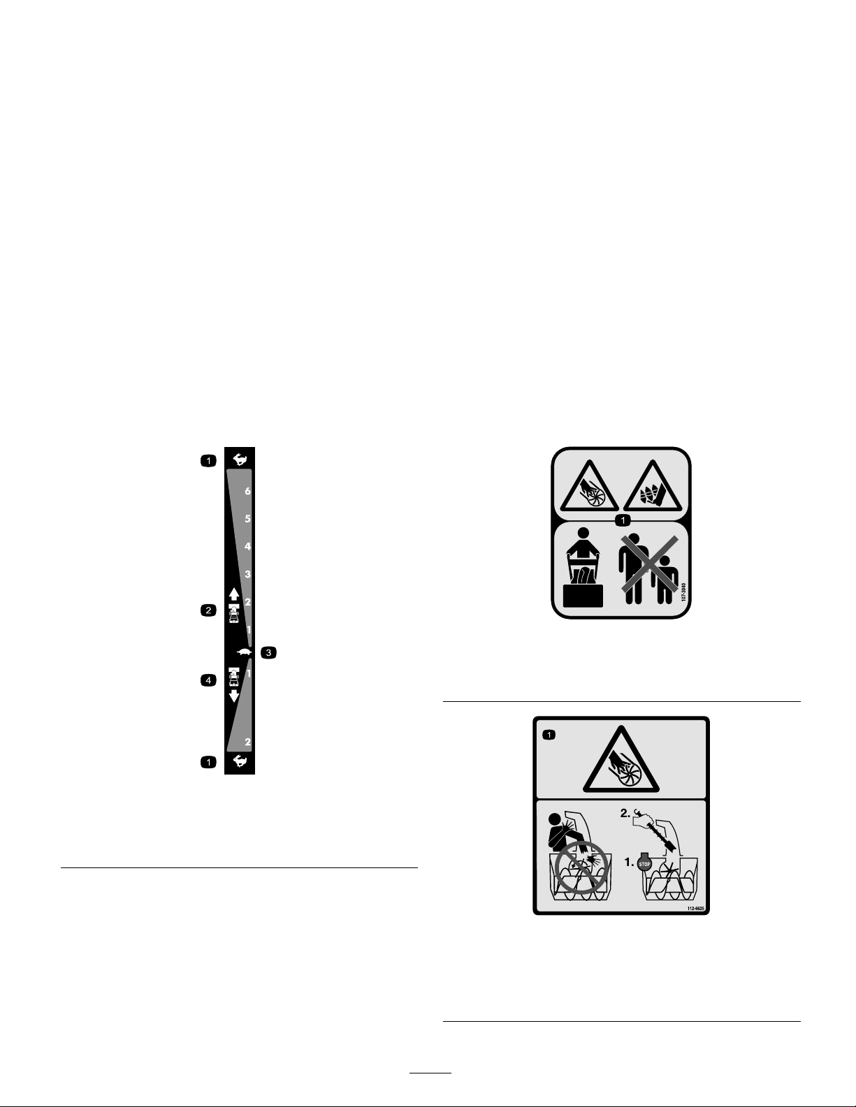
Safety and Instructional Decals
Important: Safety and instr uction decals ar e located near ar eas of potential danger . R eplace dama ged decals.
106-4525
Reorder part no. 112-6631
1. Fast
2. Forward speeds 4. Reverse speeds
3. Slow
107-3040
1. Cutting dismemberment, impeller and cutting dismemberment,
auger hazards—keep bystanders a safe distance from the
snowthrower.
112-6625
Reorder part no. 112-6629
1. Cutting/dismemberment hazard, impeller—do not place your
hand in the chute; stop the engine before leaving the operator’s
position, use the tool to clear the chute.
4
Page 5
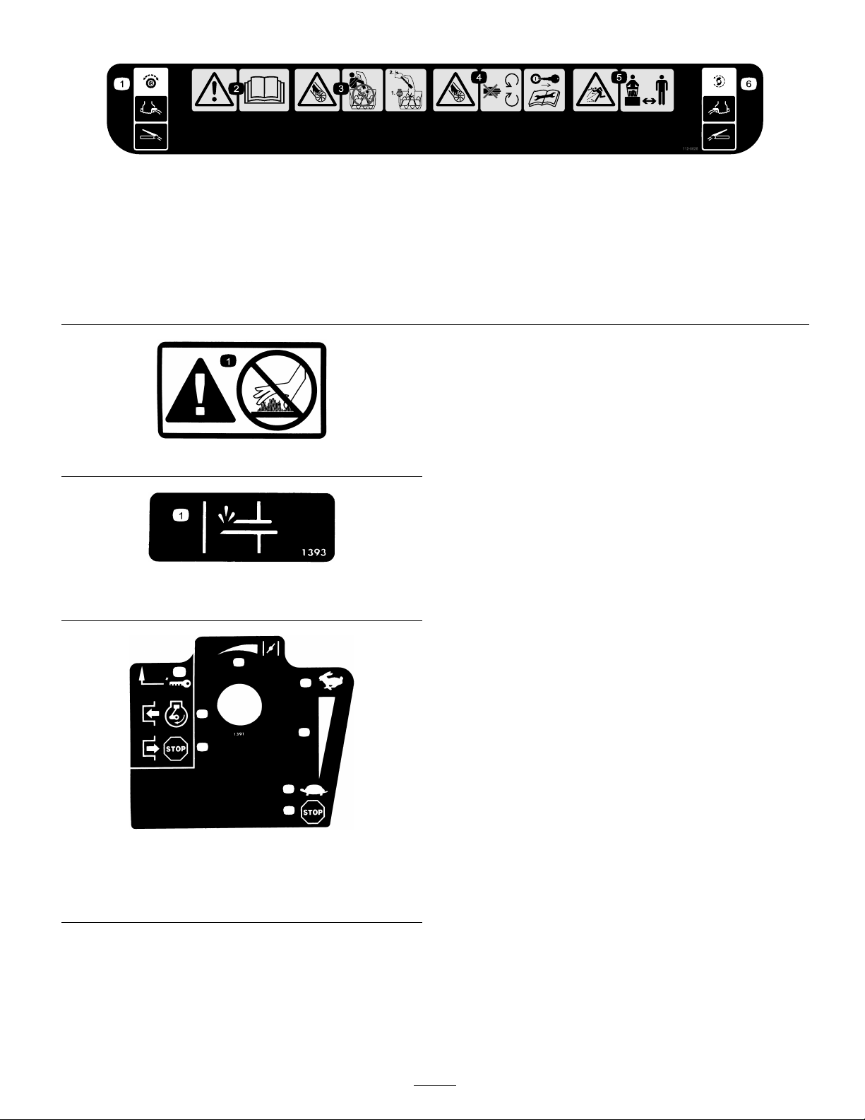
1. Traction drive—squeeze the lever to engage;
1
2
3
4
5
6
5
7
release the lever to disengage.
2. Warning—read the Operator’s Manual.
1. Warning—hot surface, do not touch
Tecumseh Part No. 36501
1. Primer
112-6626
3. Cutting/dismemberment hazard,
impeller—do not place your hand in the
chute; stop the engine before leaving the
operator’s position, use the tool to clear the
chute.
4. Cutting/dismemberment hazard,
impeller—keep away from moving parts;
remove the ignition key and read the
instructions before servicing or performing
maintenance.
5. Thrown object hazard—keep bystanders a
safe distance from the snowthrower.
6. Auger/impeller drive—squeeze the lever to
engage; release the lever to disengage.
Tecumseh Part No. 35077
1. Key ignition
2. Engage to start the engine 6. Slow
3. Disengage to stop the engine 7. Stop the engine
4. Fast
5. Increasing scale
5
Page 6
Setup
Loose Parts
Use the chart below to verify that all parts have been shipped.
Step
Handle bolts
1.
2.
3.
4.
5.
6.
Curved washers
Locknuts
No parts required
Carriage bolts
Locknuts
No parts required
No parts required
No parts required
Description
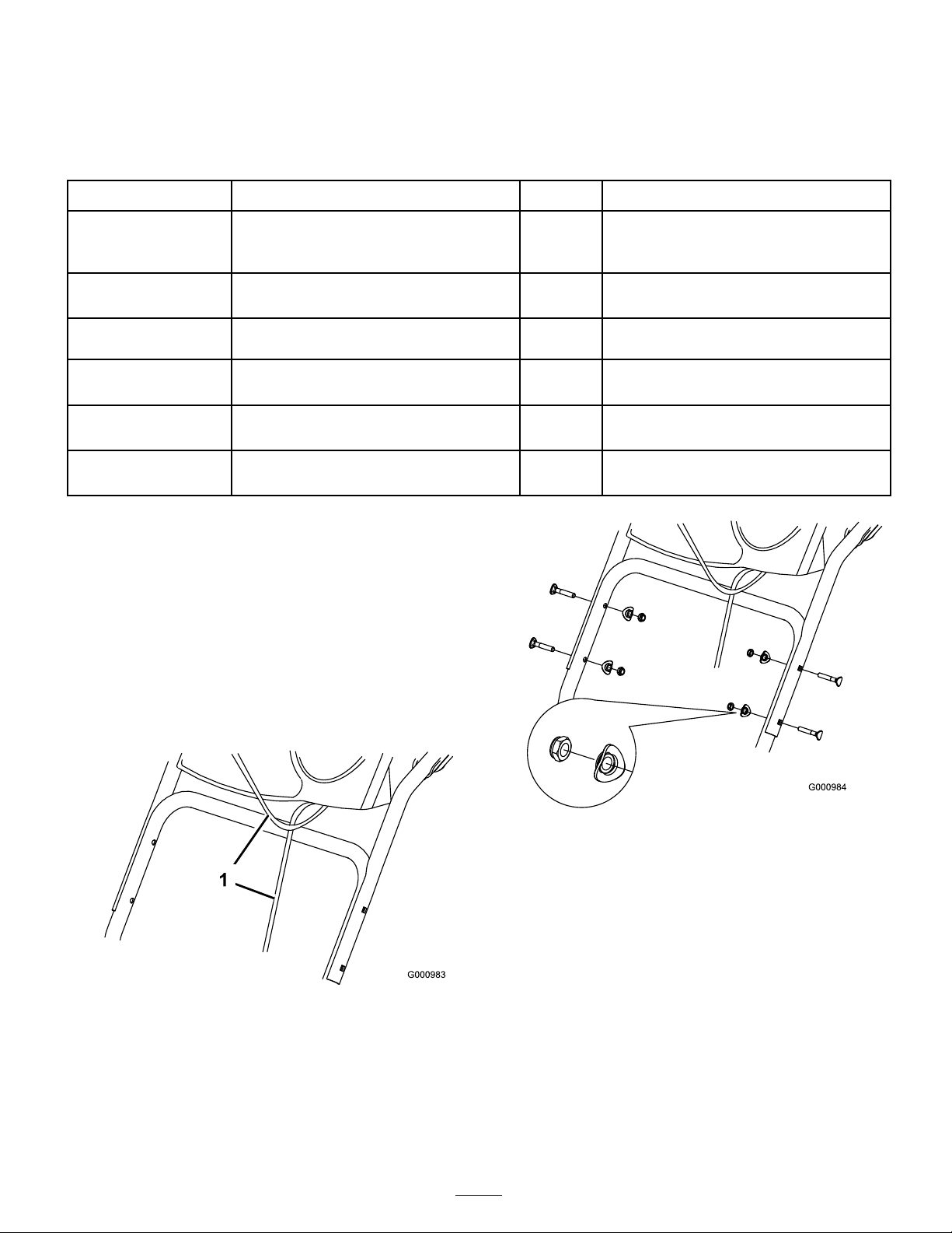
1. Installing the Upper Handle
Note: Do not remo v e the r ubber band until y ou ha v e
installed the upper handle .
1. Lift and rotate the upper handle and position it o v er
the lo w er handle ( Figure 3 ).
Qty.
4
4
4
–
2
2
–
–
–
Install the upper handle.
Install the traction control linkage.
Install the chute control rod.
Fill the engine with oil.
Check the tire pressure.
Check the skids and scraper.
Use
Important: R oute the ca bles attached to the
Quick Stick inside the upper handle legs and
ensur e that the ca bles and the wir e f or the headlight
ar e not pinched betw een the handle sections.
Figure 3
1. Cables
2. Secure the upper handle with 4 handle bolts , 4 cur v ed
w ashers , and 4 loc kn uts from the loose par ts bag ( Figure
4 ).
Figure 4
2. Installing the Traction
Control Linkage
1. R emo v e the hair pin cotter and w asher from the lo w er
end of the speed control rod and inser t the lo w er end
of the rod into the lo w er link ar m so that the bent end
of the speed control rod faces rearw ard ( Figure 5 ).
6
Page 7
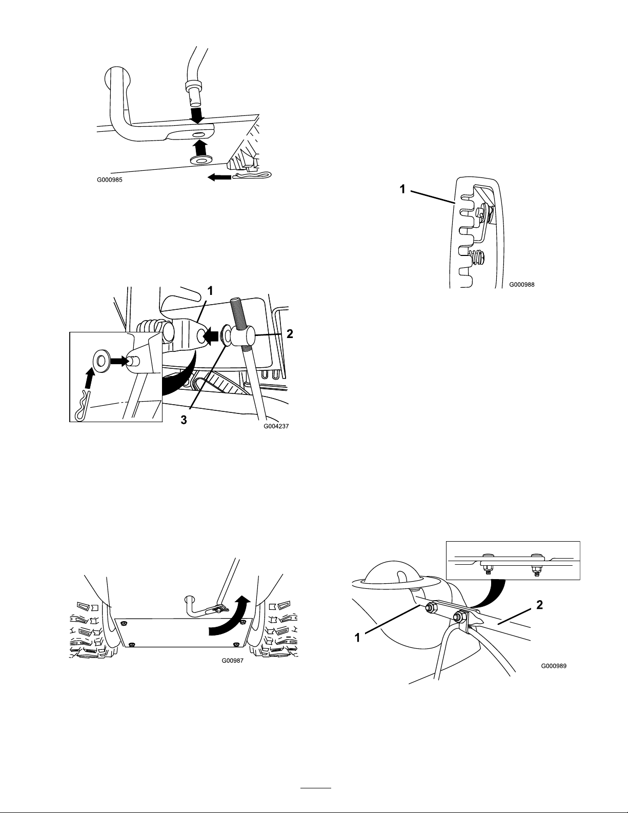
Figure 5
2. Secure the lo w er end of the speed control rod with the
w asher and hair pin cotter that y ou previously remo v ed.
3. R emo v e the hair pin cotter and the outer w asher from
the tr unnion on the upper end of the speed control
rod ( Figure 6 ).
Note: If the tr unnion does not fit into the hole when
y ou lift up on the speed control rod, rotate the tr unnion
upw ard or do wnw ard on the speed control rod until
it fits .
7. Secure the tr unnion and upper end of the speed control
rod with the outer w asher and a hair pin cotter y ou
previously remo v ed.
Note: F or easier installation, look do wn through the
opening in the speed selector ( Figure 8 ).
Figure 8
1. Speed selector
3. Installing the Chute Control
Figure 6
1. Speed selector lever 3. Flat washer
2. Trunnion
Note: T o mak e installation easier , lea v e the flat w asher
on the tr unnion ( Figure 6 ).
4. Shift the speed selector lev er into P osition R2.
5. R otate the lo w er link ar m fully upw ard
(countercloc kwise) ( Figure 7 ).
Rod
1. Unwrap the Quic k Stic k and rotate it so that it is upright
and in the center .
2. Hold the blue trig g er cap do wn and pull the lev er fully
rearw ard.
Note: T he disc harg e c hute and deflector should face
forw ard. If they do not, hold the blue trig g er cap
do wn (but do not mo v e the Quic k Stic k) and rotate the
disc harg e c hute until they do .
3. Align the flattened bac k end of the long c hute control
rod with the flattened front end of the shor t rod
that extends from the control panel so that they nest
tog ether ( Figure 9 ).
Figure 7
6. Lift up on the speed control rod and inser t the tr unnion
into the hole in the speed selector lev er ( Figure 6 ).
Figure 9
1. Short rod 2. Long chute control rod
4. Inser t the front end of the rod into the opening in the
bac k of the c hute g ear co v er until it slides into the c hute
g ear ( Figure 10 ).
7
Page 8
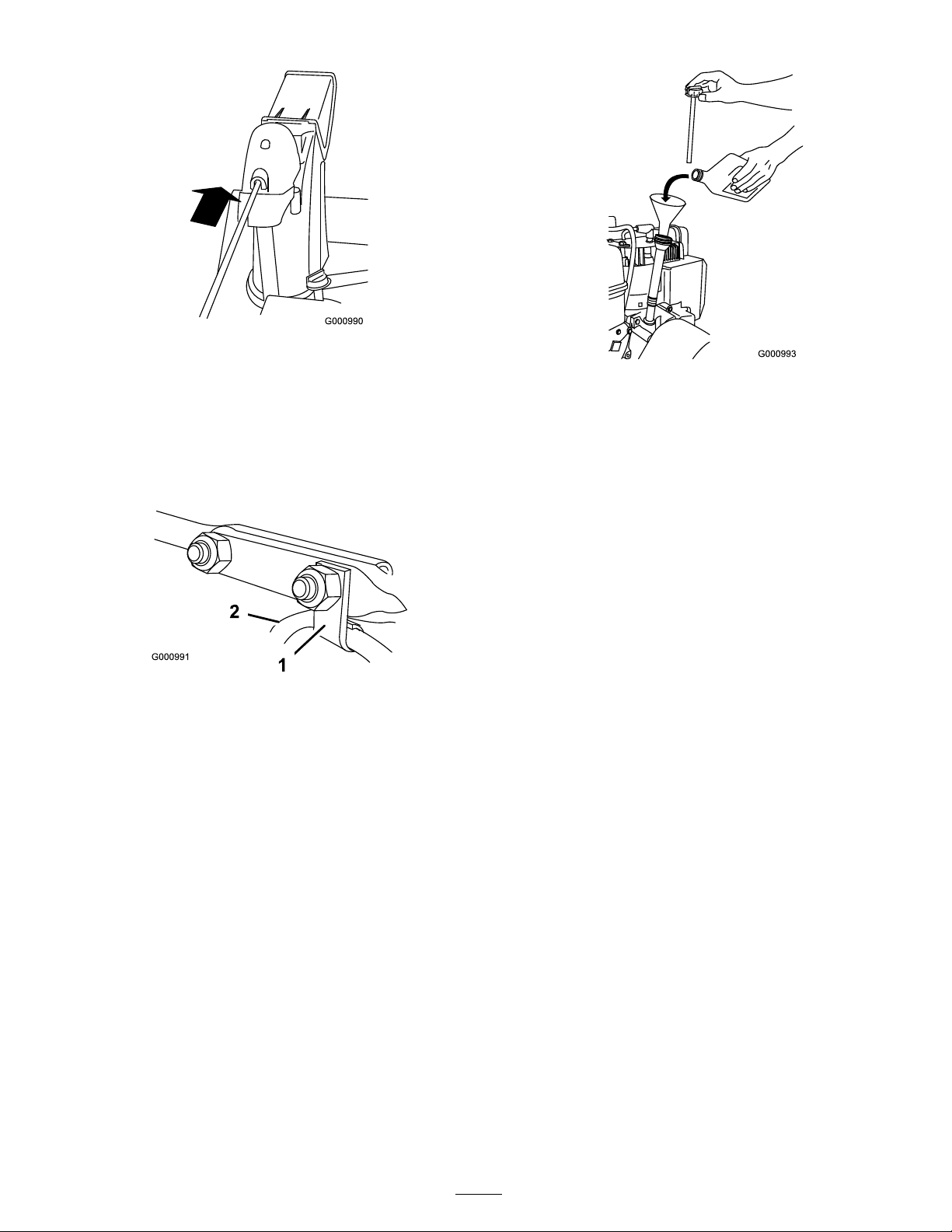
Figure 10
5. Align the holes in the nested ends of the rods and inser t
2 car riag e bolts (in the loose par ts bag) through the
shor t rod from the left side of the sno wthro w er (from
the operating position).
6. Inser t the cable clip that suppor ts the deflector cable
onto the forw ard car riag e bolt, and secure the car riag e
bolts with loc kn uts from the loose par ts bag ( Figure 11 ).
Figure 11
1. Cable clip 2. Deector cable
7. Hold the blue trig g er cap do wn and rotate the Quic k
Stic k in a circle to ensure that the c hute and deflector
operate smoothly .
Figure 12
2. Install the dipstic k securely .
Note: Do not spill oil around the oil fill tube; oil could
leak onto traction par ts and cause the traction to slip .
5. Checking the Tire Pressure
T he tires are o v erinflated at the factor y for shipping . R educe
the pressure equally in both tires to betw een 17 and 20 psi
(116 and 137 kP a).
6. Checking the Skids and
Scraper
R efer to Chec king and Adjusting the Skids and Scraper in
Maintenance .
4. Filling the Engine with Oil
Y our sno wthro w er comes with 26 oz. of oil in the engine .
Note: Before star ting the engine , c hec k the oil lev el and
add oil if necessar y .
Max. fill: 26 oz. (0.77 l), type: automoti v e deterg ent oil with
an API ser vice classification of SF , SG , SH, SJ , SL, or higher .
• F or temperatures abo v e 32°F (0°C), use SAE 30W .
• F or temperatures betw een 0°F and 32°F (-18°C to 0°C),
use SAE 5W30 or SAE 10W .
• F or air temperatures belo w 0°F (-18°C), use SAE 0W30.
1. R emo v e the dipstic k and slo wl y pour oil into the oil
fill tube to raise the oil lev el to the Full mark on the
dipstic k. Do not o v erfill ( Figure 12 ).
8
Page 9
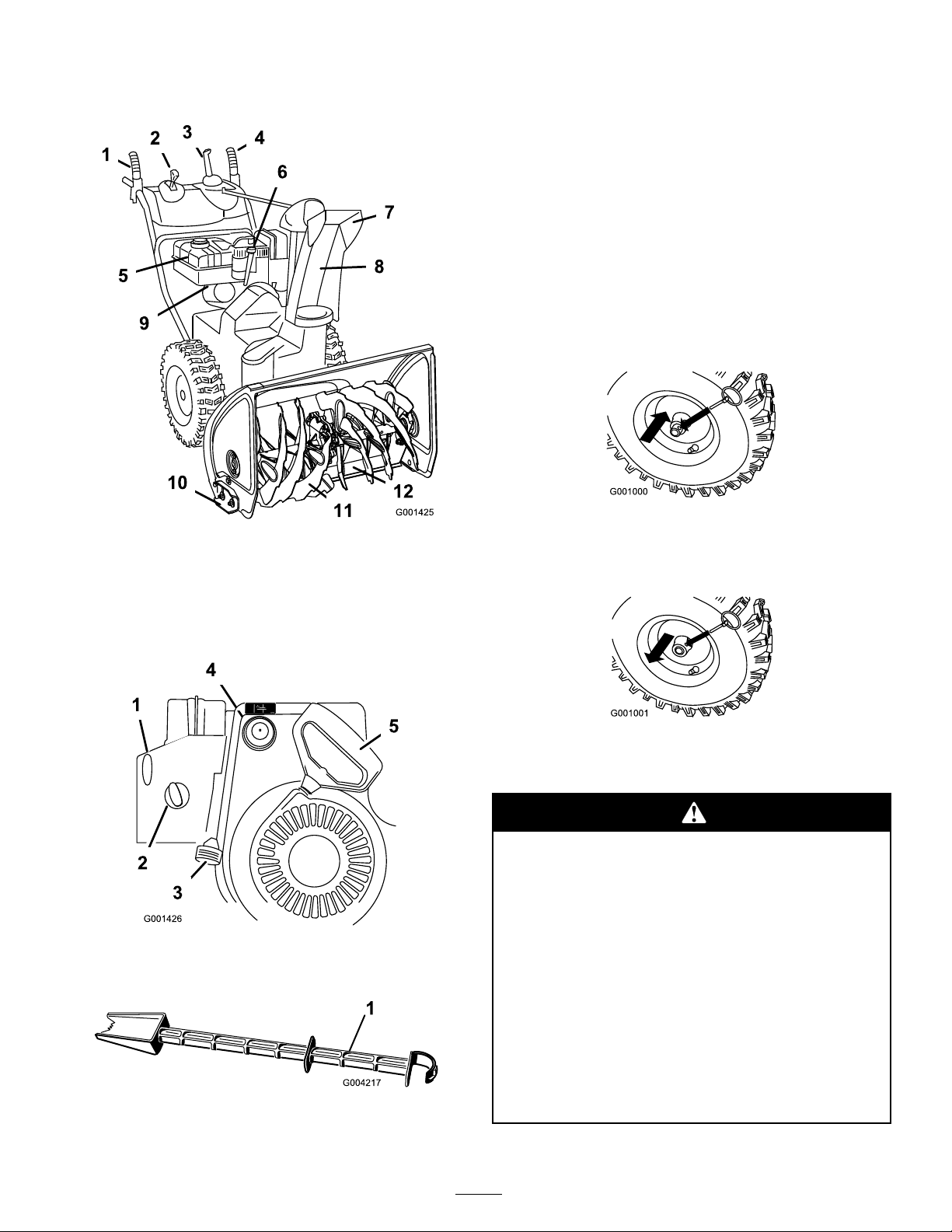
Product Overview
Operation
Note: Deter mine the left and right sides of the mac hine
from the nor mal operating position.
Freewheeling or Using the
Self-propel Drive
Y ou can operate the sno wthro w er with the self-propel
feature eng ag ed or diseng ag ed (freewheeling).
T o freewheel, slide the wheels inw ard and inser t the axle
pins through the outer axle holes , but not through the wheel
hubs ( Figure 16 ).
Figure 16
Figure 13
1. Auger/impeller lever 7. Chute deector
2. Speed selector lever 8. Discharge chute
3. Quick Stick™ discharge chute
control
4. Traction lever
5. Fuel tank
6. Engine oil ll tube/dipstick
Figure 14
1. Ignition switch
2. Choke 5. Recoil starter
3. Throttle
9. Fuel shutoff valve
10. Skid (2)
11. Auger
12. Scraper
4. Primer
T o self-propel, slide the wheels outw ard and inser t the axle
pins through the holes in the wheel hubs and the inner axle
holes ( Figure 17 ).
Figure 17
Filling the Fuel Tank
Gasoline is extr emel y flamma ble and explosi v e. A
fir e or explosion fr om gasoline can bur n y ou and
other s.
• T o pr ev ent a static charge fr om igniting the
gasoline, place the container and/or sno wthr o w er
on the g r ound bef or e filling , not in a v ehicle or
on an object.
• Fill the tank outdoor s when the engine is cold.
W ipe up spills.
Figure 15
1. Snow cleanout tool (attached to the handle)
• Do not handle gasoline when smoking or ar ound
an open flame or spar ks.
• Stor e gasoline in an appr o v ed fuel container , out
of the r each of childr en.
9
Page 10

Fill the fuel tank with fresh unleaded regular g asoline from
a major name-brand ser vice station ( Figure 18 ).
Important: T o r educe star ting pr oblems, add fuel
sta biliz er to the fuel all season, mixing it with gasoline
less than 30 days old. Do not add oil to the gasoline.
Figure 21
4. R otate the c hok e to the On position ( Figure 22 ).
Figure 18
Starting the Engine
1. Connect the spark plug wire ( Figure 19 ).
Figure 19
2. Mo v e the throttle to the F ast position ( Figure 20 ).
Figure 22
5. Inser t the ignition k ey ( Figure 23 ).
Figure 23
6. Fir mly push in the primer 3 times with y our thumb ,
holding the primer in for a second before releasing it
eac h time ( Figure 24 ).
Figure 20
3. R otate the fuel shutoff v alv e countercloc kwise to open
it ( Figure 21 ).
Figure 24
Note: T ak e y our glo v e off when y ou push in the
primer so that air cannot escape from the primer hole .
Note: Priming ex cessi v ely ma y flood the engine and
prev ent it from star ting .
7. Pull the recoil star ter ( Figure 25 ).
10
Page 11
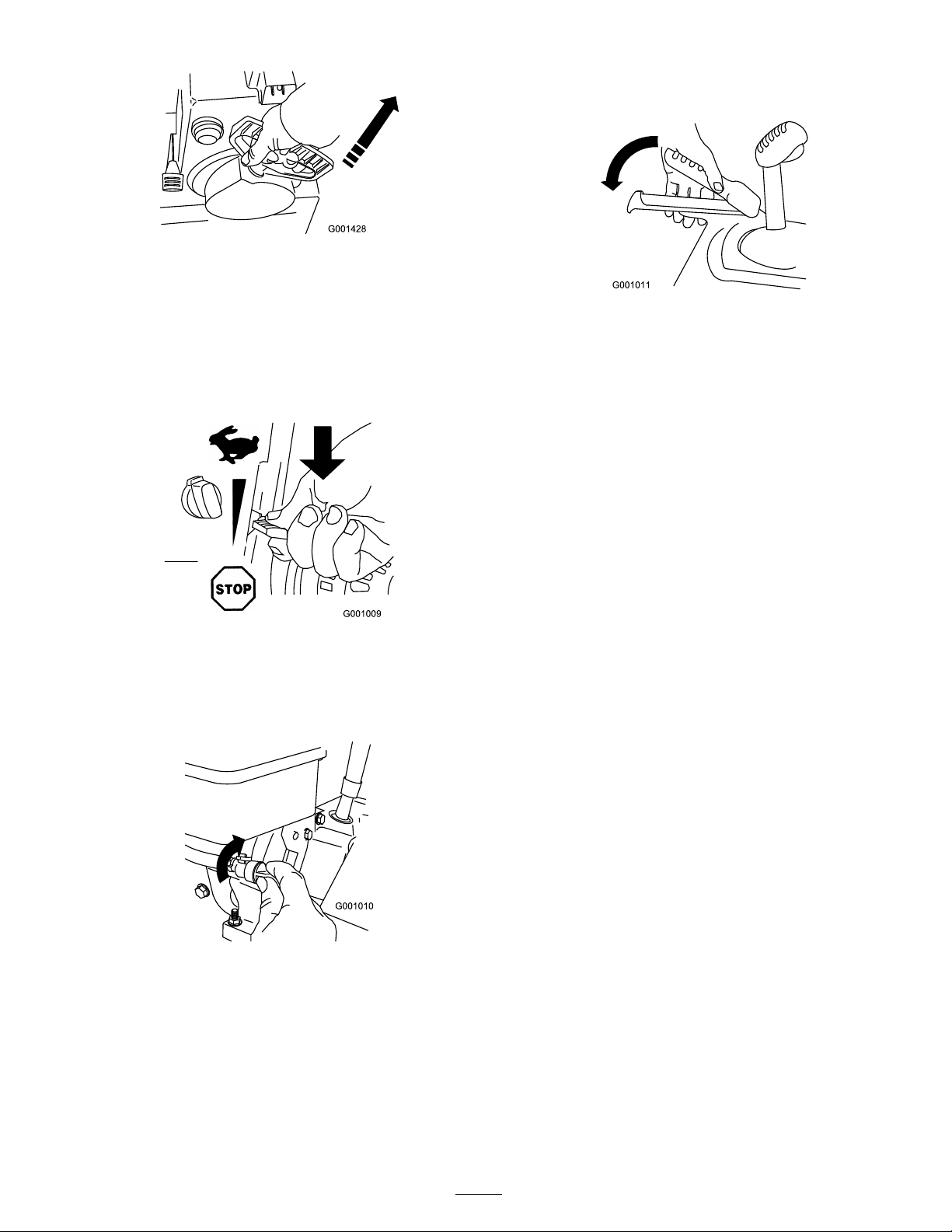
Figure 25
8. W hen the engine star ts , set the c hok e to the
3/4 position. As the engine w ar ms up , set the c hok e
to the 1/2 position. W hen the engine is w ar m, set the
c hok e to the Off position.
Stopping the Engine
1. Mo v e the throttle to the Stop position ( Figure 26 ).
1. T o eng ag e the traction dri v e , squeeze the left hand
(traction) lev er to the handg rip ( Figure 28 ).
Figure 28
2. T o stop the traction dri v e , release the traction lev er .
3. Chec k to ensure that the speed selector operates
properly:
• If the sno wthro w er does not mo v e or mo v es
forw ard when it is in P osition R1, remo v e the
tr unnion from the speed selector lev er , tur n the
tr unnion do wnw ard (cloc kwise) on the speed
control rod, then install the tr unnion.
• If the sno wthro w er does not mo v e or mo v es
rearw ard when it is in P osition 1 (forw ard), remo v e
the tr unnion from the speed selector lev er , tur n the
tr unnion upw ard (countercloc kwise) on the speed
control rod, then install the tr unnion.
Figure 26
2. W ait for all mo ving par ts to stop before lea ving the
operating position.
3. Close the fuel shutoff v alv e b y rotating it cloc kwise
( Figure 27 ).
Figure 27
4. Pull the recoil star ter 3 or 4 times . T his helps prev ent
the recoil star ter from freezing up .
Operating the Traction Drive
Note: R efer to Installing the T raction Control
Linkag e .
Note: If the sno wthro w er mo v es when the
traction lev er is in the released position, c hec k the
traction cable (refer to Chec king and Adjusting
the T raction Cable) or tak e the sno wthro w er to an
A uthorized Ser vice Dealer for ser vice .
Important: T o operate the traction dri v e, y ou
must operate the sno wthr o w er with the self-pr opel
featur e enga ged. R efer to F r eewheeling or Using the
Self-pr opel Dri v e.
11
Page 12
Operating the Speed Selector
Operating the Quick Stick™
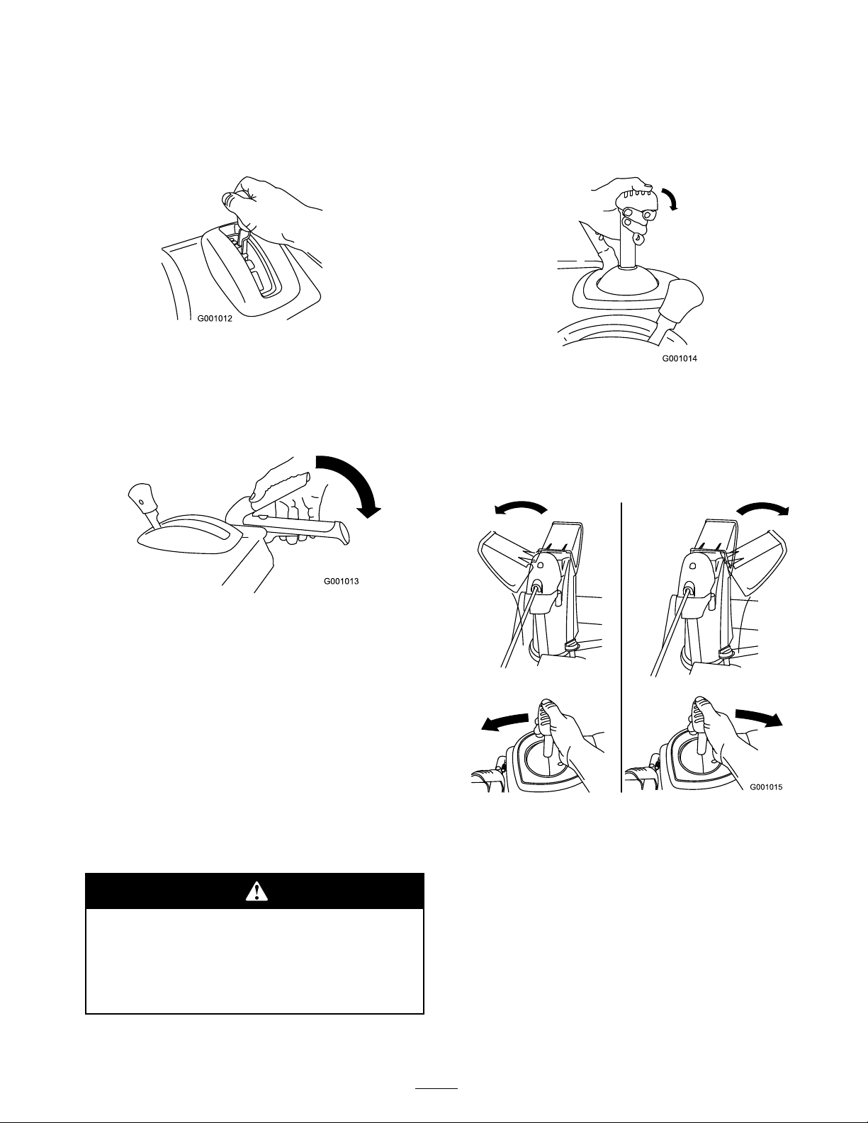
T he speed selector has 6 forw ard and 2 rev erse g ears . T o
c hang e speeds , release the traction lev er and shift the speed
selector lev er to the desired position ( Figure 29 ). T he lev er
loc ks in a notc h at eac h speed selection.
Figure 29
Operating the Auger/Impeller
Drive
1. T o eng ag e the aug er/ impeller dri v e , squeeze the right
hand (aug er/ impeller) lev er to the handg rip ( Figure 30 ).
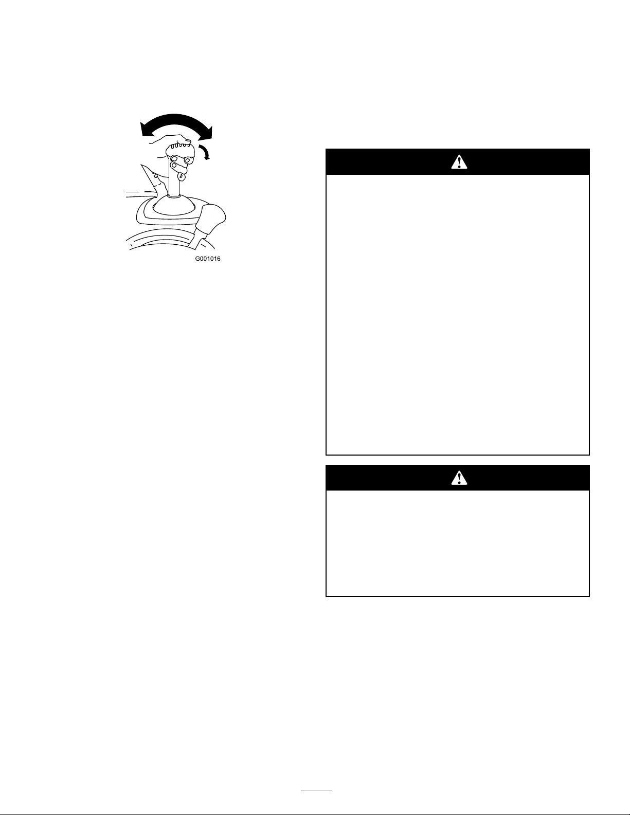
Hold the blue trig g er cap do wn to use the Quic k Stic k to
mo v e the disc harg e c hute and the c hute deflector . R elease
the trig g er cap to loc k the disc harg e c hute and c hute
deflector into position ( Figure 31 ).
Figure 31
Moving the Discharge Chute
Hold the blue trig g er cap do wn and mo v e the Quic k Stic k
to the left to mo v e the disc harg e c hute to the left; mo v e
the Quic k Stic k to the right to mo v e the disc harg e c hute to
the right ( Figure 32 ).
Figure 30
2. T o stop the aug er and impeller , release the right hand
lev er .
Important: W hen y ou enga ge both the
auger/impeller lev er and the traction lev er , the
traction lev er locks the auger/impeller lev er do wn,
fr eeing y our right hand. T o r elease both lev er s,
simpl y r elease the left hand (traction) lev er .
3. If the aug er and impeller contin ue to rotate when y ou
release the aug er/impeller lev er , do not operate the
sno wthro w er . Chec k the aug er/impeller cable (refer to
Chec king and Adjusting the A ug er/Impeller Cable) and
adjust it if necessar y . Otherwise , tak e the sno wthro w er
to an A uthorized Dealer for ser vice .
If the auger and impeller contin ue to r otate when
y ou r elease the auger/impeller lev er , y ou could
seriousl y injur e y our self or other s.
Do not operate the sno wthr o w er . T ak e it to an
Authoriz ed Ser vice Dealer f or ser vice.
Figure 32
• If the c hute does not mo v e , refer to Adjusting the
Disc harg e Chute Latc h.
• If the c hute does not tur n as far to the left as it does to
the right, ensure that the cable is routed to the inside of
the handles . R efer to Installing the Upper Handle .
• If the c hute does not loc k into place when y ou release
the trig g er cap , refer to Adjusting the Disc harg e Chute
Latc h.
12
Page 13
Moving the Chute Deector
Hold the blue trig g er cap do wn and mo v e the Quic k Stic k
forw ard to lo w er the c hute deflector; mo v e it rearw ard to
raise the c hute deflector ( Figure 33 ).
Figure 33
Unclogging the Discharge
Chute
If the aug er/impeller is r unning but there is no sno w
coming out of the disc harg e c hute , the disc harg e c hute ma y
be clog g ed.
• T o unclog the disc harg e c hute , sta y in the operating
position and release the left hand (traction) lev er . W hile
r unning the aug er/impeller , push do wn on the handles
to raise the front of the sno wthro w er a few inc hes
(centimeters) off the pa v ement. T hen lift the handles
quic kly to bump the front of the sno wthro w er on the
pa v ement. R e peat if necessar y until a stream of sno w
comes out the disc harg e c hute .
mo ving par ts to stop , and remo v e all ice and sno w from
the sno wthro w er .
• With the engine off , pull the recoil star ter handle sev eral
times to prev ent the recoil star ter from freezing up .
Operating Tips
W hen the sno wthr o w er is in operation, the impeller
and auger can r otate and cut of f or injur e hands and
feet.
• Bef or e adjusting , cleaning , inspecting ,
tr oubleshooting , or r epairing the sno wthr o w er ,
stop the engine and w ait f or all mo ving par ts
to stop . Disconnect the wir e fr om the spar k
plug and k eep it a w ay fr om the plug to pr ev ent
someone fr om accidentall y star ting the engine.
• R emo v e an obstr uction fr om the discharge
chute; r efer to Unclo g ging the Discharge Chute.
If necessar y , use the sno w cleanout tool, not
y our hands, to r emo v e an obstr uction fr om the
discharge chute.
• Stay behind the handles and a w ay fr om
the discharge opening while operating the
sno wthr o w er .
• K eep f ace, hands, feet, and an y other par t of y our
body or clothing a w ay fr om concealed, mo ving ,
or r otating par ts.
• If y ou cannot unclog the disc harg e c hute b y bumping
the front of the sno wthro w er , stop the engine, w ait
f or all mo ving par ts to stop , and use the sno w
cleanout tool; nev er use y our hand.
Important: Unclo g ging the discharge chute
by bumping the fr ont of the sno wthr o w er on the
pa v ement may cause the skids to mo v e. Adjust the
skids and tighten the skid bolts secur el y .
Preventing Freeze-up
• In sno wy and cold conditions , some controls and
mo ving par ts ma y freeze . Do not use ex cessi v e f orce
when tr ying to operate fr oz en contr ols. If y ou ha v e
difficulty operating any control or par t, star t the engine
and let it r un for a few min utes .
• After using the sno wthro w er , let the engine r un for
a few min utes to prev ent mo ving par ts from freezing .
Eng ag e the aug er/impeller to clear any remaining sno w
from inside the housing . R otate the Quic k Stic k to
prev ent it from freezing . Stop the engine , w ait for all
T he r otor blades can thr o w stones, toys, and other
f or eign objects and cause serious per sonal injur y to
the operator or to bystander s.
• K eep the ar ea to be clear ed fr ee of all objects that
the r otor blades could pick up and thr o w .
• K eep all childr en and pets a w ay fr om the ar ea
of operation.
• Alw a ys set the throttle to the F ast position when
thro wing sno w .
• If the engine slo ws do wn under a load or the wheels
slip , shift the sno wthro w er into a lo w er g ear .
• If the front of the sno wthro w er rides up , shift the
sno wthro w er into a lo w er g ear . If the front contin ues to
ride up , lift up on the handles .
13
Page 14
Maintenance
Note: Deter mine the left and right sides of the mac hine from the nor mal operating position.
Recommended Maintenance Schedule(s)
Maintenance Service
Interval
After the rst 2 operating
hours
Before each use or daily
Yearly
Yearly or before storage
Important: Y ou can find mor e inf or mation a bout maintaining and ser vicing y our sno wthr o w er at
www .T or o.com.
Important: R efer to y our engine operator’ s man ual f or additional maintenance pr ocedur es. F or engine
adjustments, r epair s, or w ar ranty ser vice not co v er ed in this man ual, contact an Authoriz ed T ecumseh Ser vicing
Dealer .
Maintenance Procedure
• Inspect the traction cable and adjust it if necessary.
• Inspect the auger/impeller cable and adjust it if necessary.
• Change the engine oil.
• Check the engine oil level and add oil if necessary.
• Check the skids and the scraper and adjust them if necessary.
• Inspect the traction cable and adjust or replace it if necessary.
• Inspect the auger/impeller cable and adjust or replace it if necessary.
• Check the auger gearbox oil and add oil if necessary.
• Change the engine oil.
• Lubricate the hex shaft.
• Inspect the spark plug. Replace and/or gap it if necessary.
• Check the air pressure in the tires and inate them to 17–20 psi (116–137 kPa).
• Drain the gasoline and run the engine to dry out the fuel tank and the carburetor
at the end of the season.
• Have an Authorized Service Dealer inspect and replace the traction drive belt
and/or the auger/impeller drive belt, if necessary.
Preparing for Maintenance
1. Mo v e the sno wthro w er to a lev el surface .
2. Stop the engine and w ait for all mo ving par ts to stop .
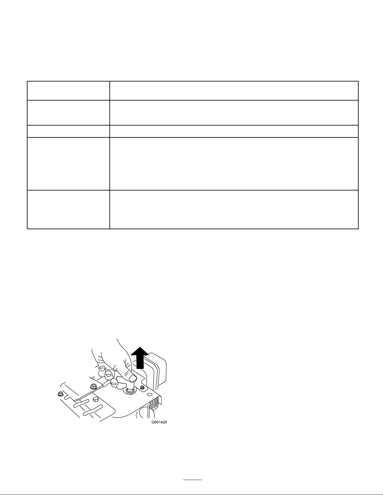
3. Disconnect the spark plug wire ( Figure 34 ).
Figure 34
Checking the Engine Oil Level
Eac h time before using the sno wthro w er , c hec k the oil lev el
in the engine crankcase .
1. R emo v e the dipstic k, wipe it clean, then fully install the
dipstic k.
2. R emo v e the dipstic k and c hec k the oil lev el ( Figure 35 ).
If the oil lev el is belo w the Add mark on the dipstic k,
add oil. R efer to Filling the Engine with Oil.
14
Page 15
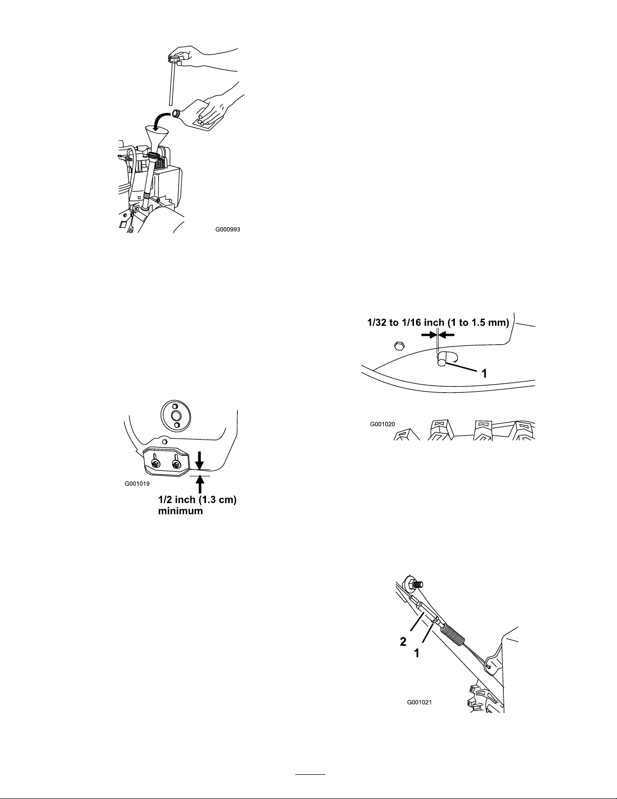
Figure 35
Checking and Adjusting the
Skids and Scraper
Chec k the skids and the scraper to ensure that the aug er
does not contact the pa v ed or g ra v el surface . Adjust the
skids and the scraper as needed to compensate for w ear .
1. Chec k the tire pressure . R efer to Chec king the Tire
Pressure .
Note: T o quic kly adjust the skids if they loosen,
suppor t the scraper 1/8 inc h (3 mm) off the pa v ement,
then adjust the skids do wn to the pa v ement.
Note: If the skids become ex cessi v ely w or n, y ou can
tur n them o v er and set the un used side to w ard the
pa v ement.
Checking and Adjusting the
Traction Cable
Chec k and adjust the traction cable after the first 2 operating
hours , then yearly thereafter . If the sno wthro w er does not
dri v e in the forw ard or rev erse speeds or it dri v es when y ou
release the traction lev er , adjust the traction cable .
With the traction lev er diseng ag ed, c hec k the pin in the
elong ated slot in the left side of the sno wthro w er abo v e
the tire . T here should be a g ap of 1/32 to 1/16 inc h (1 to
1.5 mm) from the front of the slot to the front edg e of the
pin ( Figure 37 ).
2. Loosen the n uts that secure both skids to the aug er
sides until the skids slide up and do wn easily ( Figure 36 ).
Figure 36
3. Suppor t the side plates so that they are at least 1/2 inc h
(1.3 cm) abo v e a lev el surface .
Important: T he auger blades must be suppor ted
a bo v e the g r ound by the skids.
4. Ensure that the scraper is 1/8 inc h (3 mm) abo v e and
parallel to a lev el surface .
Note: If the pa v ement is crac k ed, rough, or unev en,
adjust the skids to raise the scraper . F or g ra v el
surfaces , adjust the skids fur ther do wn to prev ent the
sno wthro w er from pic king up roc ks .
Figure 37
1. Pin
If the left hand (traction) cable is not properly adjusted,
do the follo wing ste ps:
1. Loosen the jam n ut.
2. Loosen or tighten the tur nbuc kle to adjust the pin until
it is the proper g ap from the front edg e of the slot.
3. Tighten the jam n ut ( Figure 38 ).
5. Mo v e the skids do wn until they are ev en with the
g round.
6. Fir mly tighten the n uts that secure both skids to the
aug er sides .
Figure 38
1. Jam nut
15
2. Turnbuckle
Page 16
Checking and Adjusting the
Auger/Impeller Cable
Chec k and adjust the aug er/impeller cable after the first
2 operating hours , then yearly thereafter .
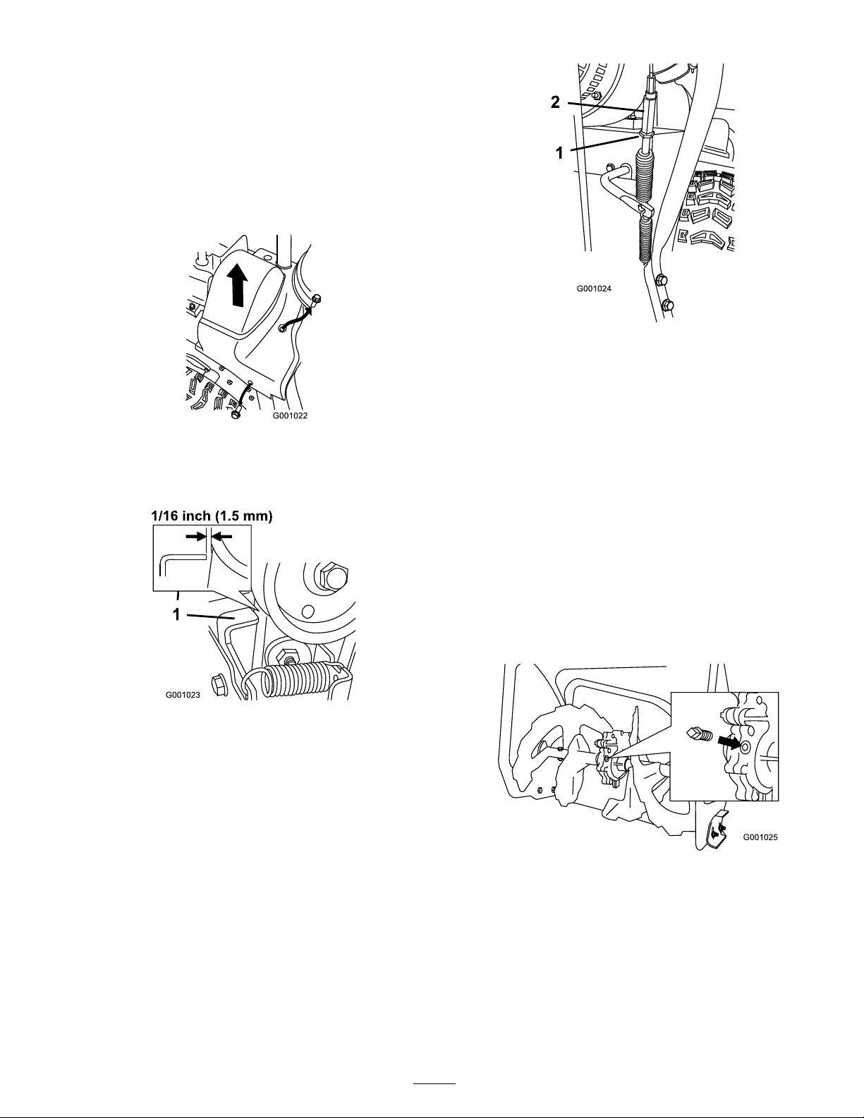
1. R emo v e the 2 screws from the right side of the belt
co v er as sho wn.
2. Lift up the right side of the belt co v er ( Figure 39 ).
Figure 39
3. With the aug er/impeller lev er diseng ag ed, ensure that
the g ap betw een the aug er clutc h assembly and the tab
is 1/16 inc h (1.5 mm) ( Figure 40 ).
Figure 41
1. Jam nut
6. Loosen or tighten the tur nbuc kle that adjusts the
tension on the cable ( Figure 41 ).
7. Adjust the tur nbuc kle until y ou obtain the proper g ap .
8. Tighten the jam n ut.
9. Inser t the 2 screws y ou previously remo v ed on the belt
co v er .
10. If the aug er/impeller cable is properly adjusted but a
problem remains , contact an A uthorized Ser vice Dealer .
2. Turnbuckle
Figure 40
1. Tab
4. If the aug er/impeller cable is not properly adjusted, do
the follo wing ste ps:
5. Loosen the jam n ut ( Figure 41 ).
Checking the Auger Gearbox
Oil Level
Chec k the aug er g earbo x oil yearly and add oil if necessar y .
1. Mo v e the sno wthro w er to a lev el surface .
2. Clean the area around the pipe plug ( Figure 42 ).
Figure 42
3. R emo v e the pipe plug from the g earbo x.
4. Chec k the oil lev el in the g earbo x. T he oil should be at
the point of o v erflo wing at the filler opening .
5. If the oil lev el is lo w , add GL-5 or GL-6, SAE 85-95
EP transmission oil to the g earbo x until the point of
o v erflo w .
Note: Do not use synthetic oil.
6. Install the pipe plug in the g earbo x.
16
Page 17
Changing the Engine Oil
Chang e the engine oil after the first 2 operating hours , then
yearly thereafter . If possible , r un the engine just before
c hanging the oil because w ar m oil flo ws better and car ries
more contaminants .
Max. fill: 26 oz. (0.77 l), type: automoti v e deterg ent oil with
an API ser vice classification of SF , SG , SH, SJ , SL, or higher .
• F or temperatures abo v e 32°F (0°C), use SAE 30W .
• F or temperatures betw een 0°F and 32°F (-18°C to 0°C),
use SAE 5W30 or SAE 10W .
• F or air temperatures belo w 0°F (-18°C), use SAE 0W30.
1. Clean the area around the oil drain cap ( Figure 43 ).
Figure 43
1. Oil drain cap
2. Slide an oil drain pan under the drain extension and
remo v e the oil drain cap .
3. Drain the oil.
Note: Dispose of the used oil properly at a local
recycling center .
4. Install the oil drain cap .
5. Fill the crankcase with oil. R efer to Filling the Engine
Crankcase with Oil.
1. Drain the g asoline from the fuel tank.
2. Tip the sno wthro w er forw ard onto its aug er housing
and bloc k it so that it cannot fall.
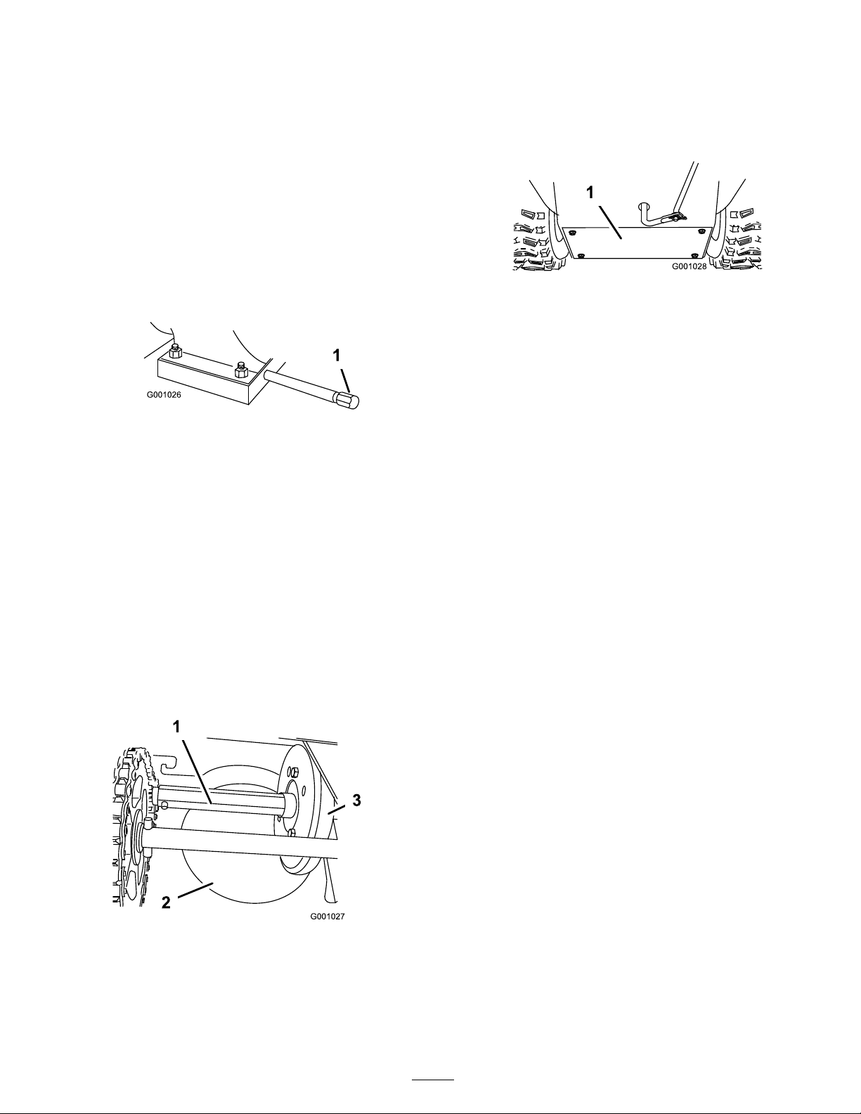
3. R emo v e the bac k co v er ( Figure 45 ).
Figure 45
1. Back cover
4. Mo v e the speed selector lev er to P osition R2.
5. Dip y our fing er in automoti v e engine oil and lightl y
lubricate hex shaft.
6. Mo v e the speed selector lev er to P osition 6.
7. Lubricate the other end of the hex shaft.
8. Mo v e the speed selector lev er forw ard and rearw ard
a few times .
9. Install the bac k co v er and retur n the sno wthro w er to
the operating position.
Lubricating the Hex Shaft
Lightly lubricate the hex shaft yearly with automoti v e engine
oil ( Figure 44 ).
Figure 44
1. Hex shaft 3. Rubber wheel
2. Aluminum friction plate
Important: Do not get oil on the r ub ber wheel or
the alumin um friction dri v e plate because the traction
dri v e will slip ( Figur e 44 ).
17
Page 18
Inspecting and Replacing the
Spark Plug
Use a Champion RJ-19LM or equi v alent spark plug . Chec k
and g ap the spark yearly , and re place the plug if necessar y .
1. Clean around the base of the spark plug .
2. R emo v e the spark plug .
3. Examine the spark plug and re place it if it is crac k ed,
fouled, dir ty , or if the electrodes are w or n.
Important: Do not clean the electr odes because
g rit could enter the cylinder and dama ge the
engine.
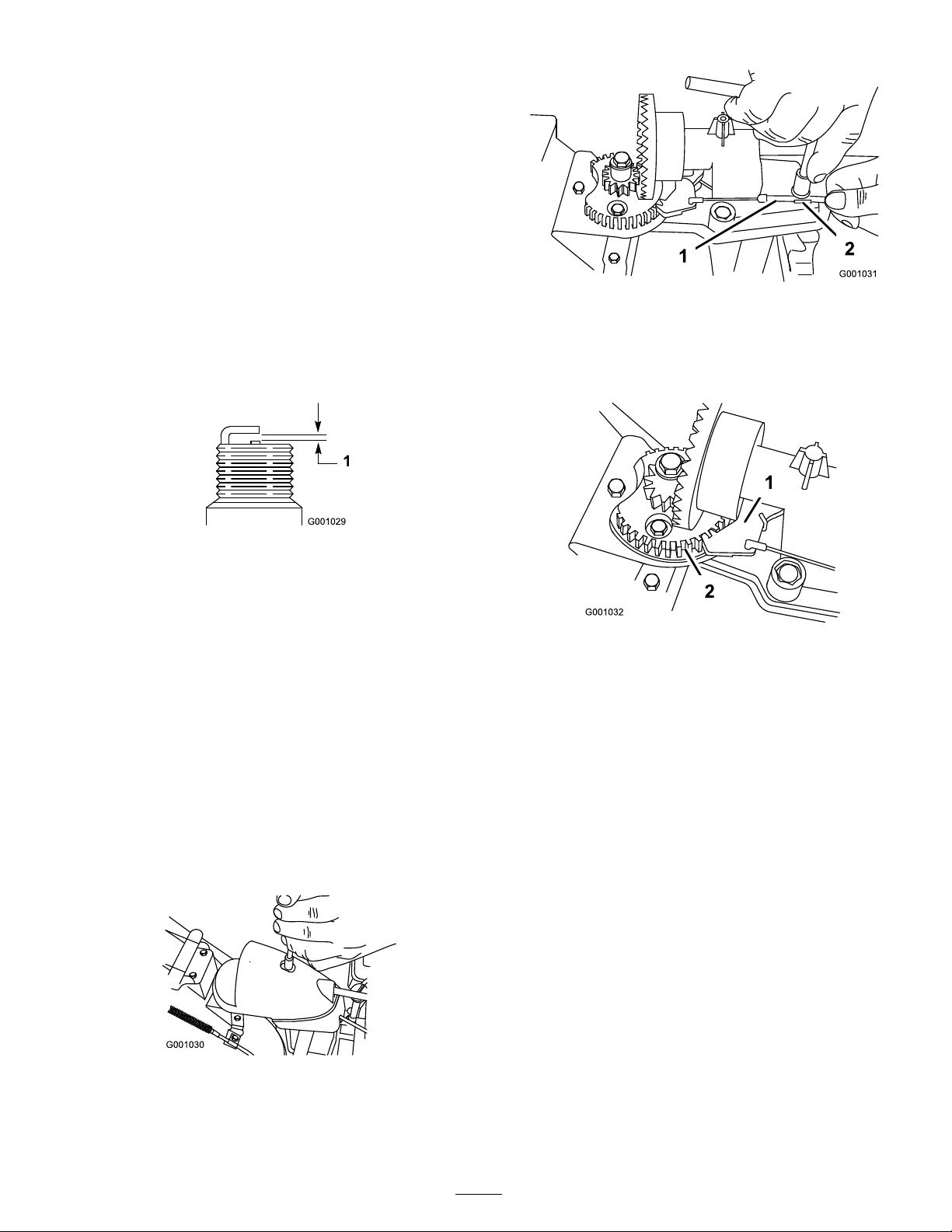
4. Set the g ap betw een the electrodes on the spark plug at
0.030 inc h (0.76 mm) ( Figure 46 ).
Figure 46
1. 0.030 inch (0.76 mm)
5. Install the spark plug b y hand and then tor que it to 15
ft-lb (20.4 N·m).
Note: If y ou do not ha v e a tor que wrenc h, tighten
the plug fir mly .
Adjusting the Discharge Chute
Latch
If the disc harg e c hute does not loc k into the desired
position or does not unloc k so that y ou can mo v e it to
another position, adjust the disc harg e c hute latc h.
1. R emo v e the fastener on the g ear co v er ( Figure 47 ), lift
the front of the co v er up , and slide it bac k and out of
the w a y .
Figure 48
1. Cable conduit 2. Cable clamp
3. Grasp the cable conduit and mo v e it to w ard the front of
the mac hine until the disc harg e c hute latc h fully eng ag es
the g ear teeth ( Figure 48 and Figure 49 ).
Figure 49
1. Discharge chute latch 2. Gear teeth
Note: T he latc h is spring loaded and will naturally
mo v e into the teeth of the g ear ( Figure 49 ).
4. R emo v e any slac k in the cable b y pulling the cable
conduit rearw ard.
5. Tighten the bolt on the cable clamp .
6. Install and secure the g ear co v er .
Replacing the Drive Belts
If the aug er/impeller dri v e belt or the traction dri v e belt
becomes w or n, oil-soak ed, or otherwise damag ed, g o to
www .T oro .com for additional ser vice infor mation or ha v e
an A uthorized Ser vice Dealer re place the belt.
Figure 47
2. Loosen the bolt on the cable clamp ( Figure 48 ).
18
Page 19

Storage
• Gasoline v apor s can explode.
• Do not stor e gasoline mor e than 30 days.
Removing the Snowthrower
from Storage
1. R emo v e the spark plug and spin the engine rapidly using
the star ter to blo w the ex cess oil from the cylinder .
2. Install the spark plug b y hand and then tor que it to
15 ft-lb (20.4 N·m).
• Do not stor e the sno wthr o w er in an enclosur e
near an open flame.
• Allo w the engine to cool bef or e storing it.
Preparing the Snowthrower
for Storage
1. On the last refueling of the year , add fuel stabilizer to
fresh fuel as directed b y the engine man ufacturer .
2. R un the engine for 10 min utes to distribute the
conditioned fuel through the fuel system.
3. Loosen the hose clamp that secures the fuel line to the
v alv e and slide the fuel line off the fuel shutoff v alv e .
4. Open the fuel shutoff v alv e and allo w the fuel to drain
out of the fuel tank into an appro v ed fuel container .
5. Install the fuel line onto the fuel shutoff v alv e and
secure it with a hose clamp .
6. R un the sno wthro w er until the engine stops from
r unning out of fuel.
7. Prime the engine and star t it ag ain.
3. Connect the spark plug wire .
4. P erfor m the ann ual maintenance procedures as gi v en in
the R ecommended Maintenance Sc hedule .
8. Allo w the engine to r un until it stops . W hen y ou can no
long er star t the engine , it is sufficiently dr y .
9. Stop the engine and allo w it to cool.
10. R emo v e the ignition k ey .
11. Disconnect the spark plug wire .
12. R emo v e the spark plug, add 1 oz. (30 ml) of oil through
the spark plug hole , and pull the star ter rope slo wl y
sev eral times to distribute oil throughout the cylinder to
prev ent cylinder cor rosion during the off-season.
13. Loosely install the spark plug .
14. Dispose of any un used fuel properly . R ecycle it
according to local codes , or use it in y our automobile .
Note: Do not store stabilized fuel for more than
90 da ys .
15. Clean the sno wthro w er thoroughly .
16. Tighten all loose screws , bolts , and loc kn uts . R e pair or
re place any damag ed par ts .
19
Page 20

Troubleshooting
Problem
Engine does not start or starts
hard
Possible Cause Corrective Action
1. The key is not in the ignition
or is in the Stop position.
2. The choke is in the Off position
and the primer has not been
pressed.
3. The fuel shutoff valve is not
open.
4. The throttle is not in the Fast
position.
5. The fuel tank is empty or the
fuel system contains stale fuel.
6. The spark plug wire is loose or
disconnected.
7. The spark plug is pitted,
fouled, or the gap is incorrect.
8. The fuel vent cap is restricted. 8. Remove the vent restriction or
9. The engine oil level in the
engine crankcase is too low or
too high.
1. Insert the key into the ignition
and turn it to the On position.
2. Move the choke to the On
position and press the primer
3 times.
3. Open the fuel shutoff valve.
4. Move the throttle to the Fast
position.
5. Drain and/or ll the fuel tank
with fresh gasoline (not more
than 30 days old). If the
problem persists, contact an
Authorized Service Dealer.
6. Connect the wire to the spark
plug.
7. Check the spark plug and
adjust the gap if necessary.
Replace the spark plug if it is
pitted, fouled, or cracked.
replace the fuel cap.
9. Add or drain oil to adjust
the oil level in the engine
crankcase to the Full mark on
the dipstick.
Engine runs rough
1. The choke is in the On
position.
2. The fuel shutoff valve is not
completely open.
3. The fuel tank is nearly empty
or contains stale fuel.
4. The spark plug wire is loose. 4. Connect the wire to the spark
5. The spark plug is pitted,
fouled, or the gap is incorrect.
6. The engine oil level in the
engine crankcase is too low or
too high.
1. Move the choke to the Off
position.
2. Open the fuel shutoff valve.
3. Drain and ll the fuel tank
with fresh gasoline (not more
than 30 days old). If the
problem persists, contact an
Authorized Service Dealer.
plug.
5. Check the spark plug and
adjust the gap if necessary.
Replace the spark plug if it is
pitted, fouled, or cracked.
6. Add or drain oil to adjust
the oil level in the engine
crankcase to the Full mark on
the dipstick.
20
Page 21

Problem
Possible Cause Corrective Action
Engine runs, but the
snowthrower discharges snow
poorly or not at all
1. The throttle is not in the
Fast position when throwing
snow.
2. The snowthrower is moving
too fast to clear the snow.
3. You are trying to remove too
much snow per swath.
4. You are trying to remove
extremely heavy or wet snow.
5. The discharge chute is
plugged.
6. The auger/impeller drive belt
is loose or is off the pulley.
7. The auger/impeller drive belt
is worn or broken.
1. Move the throttle to the Fast
position.
2. Shift the snowthrower into a
lower gear.
3. Reduce the amount of snow
removed per swath.
4. Don’t overload the
snowthrower with extremely
heavy or wet snow.
5. Unclog the discharge chute.
6. Install and/or adjust the
auger/impeller drive belt;
refer to www.Toro.com for
servicing information or
take the snowthrower to an
Authorized Service Dealer.
7. Replace the auger/impeller
drive belt; refer to
www.Toro.com for servicing
information or take the
snowthrower to an Authorized
Service Dealer.
Discharge chute either does not
lock into place or does not move
Snowthrower does not properly
clear the snow off the surface
1. The discharge chute latch is
not properly adjusted.
1. The skids and/or scraper are
not properly adjusted.
2. The pressure in the tires is not
equal.
1. Adjust the discharge chute
latch.
1. Adjust the skids and/or the
scraper.
2. Check and adjust the pressure
in one or both tires.
21
Page 22

Page 23

International Distributor List—Consumer Products
Distributor:
Atlantis Su ve Sulama Sisstemleri Lt Turkey
Balama Prima Engineering Equip
B-Ray Corporation
Casco Sales Company
Ceres S.A
CSSC Turf Equipment (pvt) Ltd
Cyril Johnston & Co Nothern Ireland
Equiver Mexico
Femco S.A.
G.Y.K. Company ltd.
Geomechaniki of Athens
Guandong Golden Star China
Hako Gorund and Garden Sweden
Hydroturf Int. Co Dubai United Arab Emirates
Hydroturf Egypt LLC
Ibea S.p.A. Italy
Irriamc
Jean Heybroek b.v. Netherlands
Lely (U.K. ) Limited
Maquiver S.A.
Maruyama Mfg. Co. Inc.
Metra Kft
Mounteld a.s. Czech Republic
Munditol S.A.
Oslinger Turf Equipment SA Ecuador
Oy Hako Ground and Garden Ab Finland
Parkland Products Ltd New Zealand
Prochaska & Cie
RT Cohen 2004 Ltd Israel
Riversa Spain
Roth Motorgerate GmBh & Co
Sc Svend Carlsen A/S Denmark
Solvert S.A.S
Spypros Stavrinides Limited
Surge Systems India Limited India
T-Markt Logistics Ltd
Toro Australia Australia
Toro Europe BVBA
Country:
Hong Kong 852 2155 2163
Korea 82 32 551 2076
Puerto Rico
Costa Rica
Sri Lanka
Guatemala
Japan
Greece 30 10 935 0054
Egypt
Portugal
United Kingdom
Columbia
Japan
Hungary
Argentina
Austria
Germany 49 7144 2050
France
Cyprus 357 22 434131
Hungary
Belgium
Phone Number:
90 216 344 86 74
787 788 8383
506 239 1138
94 11 2746100
44 2890 813 121
52 55 539 95444
502 442 3277
81 726 325 861
86 20 876 51338
46 35 10 0000
97 14 347 9479
202 519 4308
39 0331 853611
351 21 238 8260
31 30 639 4611
44 1480 226 800
57 1 236 4079
81 3 3252 2285
36 1 326 3880
420 255 704 220
54 11 4 821 9999
593 4 239 6970
358 987 00733
64 3 34 93760
43 1 278 5100
972 986 17979
34 9 52 83 7500
45 66 109 200
33 1 30 81 77 00
91 1 292299901
36 26 525 500
61 3 9580 7355
32 14 562 960
374-0102 Rev A
Page 24

The Toro Warranty
Conditions and Products Covered
The Toro® Company and its afliate, Toro Warranty Company,
pursuant to an agreement between them, jointly promises to the
original purchaser* to repair any Toro Product used for normal
residential purposes* if defective in materials or workmanship.
The following time periods apply from the date of original
purchase:
Products
Walk Power Mowers
Rear Engine Riders 2-year limited warranty
Lawn & Garden Tractors
Electric Hand Held Products
Snowthrowers
Consumer Zero Turn
* “Original purchaser” means use the person who originally
purchased Toro products.
* “Normal residential purposes”means use of the product on
the same lot as your home. Use at more than one location is
considered commercial use, and the commercial use warranty
would apply.
Warranty Period
2-year limited warranty
2-year limited warranty
2-year limited warranty
2-year limited warranty
2-year limited warranty
Limited Warranty for Commercial Use
Toro Consumer Products and attachments used for commercial,
institutional, or rental use are warranted against defects in
materials or workmanship for the following time periods from
the date of original purchase:
Products
Walk Power Mowers
Rear Engine Riders 90 day warranty
Lawn & Garden Tractors
Electric Hand Held Products
Snowthrowers
Consumer Zero Turn
Warranty Period
90 day warranty
90 day warranty
90 day warranty
90 day warranty
45 day warranty
Instructions for Obtaining Warranty Service
If you think that your Toro Product contains a defect in materials
or workmanship, follow this procedure:
1. Contact your seller to arrange service of the product. If for
any reason it is impossible for you to contact your seller,
you may contact any Toro Authorized Distributor to arrange
service.
2. Bring the product and your proof of purchase (sales receipt)
to your seller or the Service Dealer.
If for any reason you are dissatised with the Service Dealer’s
analysis or with the assistance provided, contact the Toro
importer or contact us at:
Customer Care Department, Consumer Division
Toro Warranty Company
8111 Lyndale Avenue South
Bloomington, MN 55420-1196
Manager: Technical Product Support: 001-952-887-8248
See attached Distributor List
Owner Responsibilities
You must maintain your Toro Product by following the
maintenance procedures described in the operator’s manual.
Such routine maintenance, whether performed by a dealer or by
you, is at your expense.
Items and Conditions Not Covered
This express warranty does not cover:
• Cost of regular maintenance service or parts, such as lters,
fuel, lubricants, tune-up parts, blade sharpening, brake and
clutch adjustments.
• Any product or part which has been altered or misused
or required replacement or repair due to normal wear,
accidents, or lack of proper maintenance.
• Repairs necessary due to improper fuel, contaminants in the
fuel system, or failure to properly prepare the fuel system
prior to any period of non-use over three months.
• Engine and transmission. These are covered by the
appropriate manufacturer’s guarantees with separate terms
and conditions.
All repairs covered by this warranty must be performed by an
Authorized Toro Service Dealer using Toro approved replacement
parts.
General Conditions
The purchaser is covered by the national laws of each country.
The rights to which the purchaser is entitled with the support of
these laws are not restricted by this warranty.
374-0101 Rev A
 Loading...