

Page 1
FormNo.3365-632RevA
PowerClearSnowthrower
ModelNo.38587—SerialNo.311000001andUp
ModelNo.38593—SerialNo.311000001andUp
Operator'sManual
Introduction
Thismachineisintendedtobeusedbyresidential
homeownersorprofessional,hiredoperators.It
isdesignedprimarilyforremovingsnowfrom
pavedsurfaces,suchasdrivewaysandsidewalks,
andothersurfacesfortrafconresidentialor
commercialproperties.Itisnotdesignedfor
removingmaterialsotherthansnow,norisit
designedforclearingoffgravelsurfaces.
Readthisinformationcarefullytolearnhowtooperate
andmaintainyourmachineproperlyandtoavoidinjury
andmachinedamage.Youareresponsibleforoperating
themachineproperlyandsafely.
YoumaycontactTorodirectlyatwww .Toro.comfor
machineandaccessoryinformation,helpndinga
dealer,ortoregisteryourmachine.
Wheneveryouneedservice,genuineToroparts,or
additionalinformation,contactanAuthorizedService
DealerorToroCustomerServiceandhavethemodel
andserialnumbersofyourmachineready .
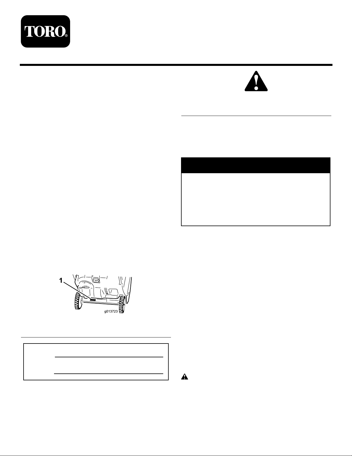
Figure1
identiesthelocationofthemodelandserialnumbers
onthemachine.Writethenumbersinthespace
provided.
Figure2
1.Safetyalertsymbol
Thismanualuses2wordstohighlightinformation.
Importantcallsattentiontospecialmechanical
informationandNoteemphasizesgeneralinformation
worthyofspecialattention.
WARNING
CALIFORNIA
Proposition65Warning
Theengineexhaustfromthisproduct
containschemicalsknowntotheStateof
Californiatocausecancer,birthdefects,
orotherreproductiveharm.
ThissparkignitionsystemcomplieswithCanadian
ICES-002.
Theenclosed
forinformationregardingtheUSEnvironmental
ProtectionAgency(EPA)andtheCalifornia
EmissionControlRegulationofemissionsystems,
maintenance,andwarranty.Replacementsmaybe
orderedthroughtheenginemanufacturer.
Engine Owner’ s Man ual
issupplied
Figure1
1.Modelandserialnumberlocation
ModelNo.
SerialNo.
Thismanualidentiespotentialhazardsandhas
safetymessagesidentiedbythesafetyalertsymbol
(Figure2),whichsignalsahazardthatmaycauseserious
injuryordeathifyoudonotfollowtherecommended
precautions.
©2010—TheT oro®Company
8111LyndaleAvenueSouth
Bloomington,MN55420
Registeratwww.Toro.com.
Safety
ThismachinemeetsorexceedstheB71.3
specicationsoftheAmericanNationalStandards
Instituteineffectatthetimeofproduction.
Readandunderstandthecontentsofthismanual
beforeyoustarttheengine.
Thisisthesafetyalertsymbol.Itisusedtoalert
youtopotentialpersonalinjuryhazards.Obeyall
safetymessagesthatfollowthissymboltoavoid
possibleinjuryordeath.
Improperlyusingormaintainingthismachine
couldresultininjuryordeath.Toreducethis
OriginalInstructions(EN)
PrintedintheUSA
AllRightsReserved
Page 2

potential,complywiththefollowingsafety
instructions.
–Iffuelisspilledonclothing,changeclothing
immediately.
Thismachineiscapableofamputatinghandsand
feetandofthrowingobjects.Failuretoobservethe
followingsafetyinstructionscouldresultinserious
injury.
Training
•Read,understand,andfollowallinstructionsonthe
machineandinthemanual(s)beforeoperatingthis
machine.Bethoroughlyfamiliarwiththecontrols
andtheproperuseofthemachine.Knowhowto
stopthemachineanddisengagethecontrolsquickly.
•Neverallowchildrentooperatethemachine.Never
allowadultstooperatethemachinewithoutproper
instruction.
•Keeptheareaofoperationclearofallpersons,
particularlysmallchildren.
•Exercisecautiontoavoidslippingorfalling.
Preparation
•Thoroughlyinspecttheareawherethemachineis
tobeusedandremovealldoormats,sleds,boards,
wires,andotherforeignobjects.
•Donotoperatethemachinewithoutwearing
adequatewintergarments.Avoidloosetting
clothingthatcangetcaughtinmovingparts.Wear
footwearthatwillimprovefootingonslippery
surfaces.
•Handlefuelwithcare;itishighlyammable.
–Useanapprovedfuelcontainer.
–Neveraddfueltoarunningengineorhotengine.
–Fillfueltankoutdoorswithextremecare.Never
llfueltankindoors.
–Neverllcontainersinsideavehicleorona
truckortrailerbedwithaplasticliner.Always
placecontainersontheground,awayfromyour
vehicle,beforelling.
–Whenpractical,removegas-poweredmachinery
fromthetruckortrailerandrefuelitonthe
ground.Ifthisisnotpossible,thenrefuelsuch
machineryonatrailerwithaportablecontainer,
ratherthanfromagasolinedispensernozzle.
–Keepthenozzleincontactwiththerimof
thefueltankorcontaineropeningatalltimes,
untilrefuelingiscomplete.Donotuseanozzle
lock-opendevice.
–Replacegasolinecapsecurelyandwipeupspilled
fuel.
•Useextensioncordsandreceptaclesasspecied
bythemanufacturerforallmachineswithelectric
startingmotors.
•Donotattempttoclearsnowfromagravelor
crushedrocksurface.Thismachineisintendedfor
useonlyonpavedsurfaces.
•Neverattempttomakeanyadjustmentswhile
theengineisrunning(exceptwhenspecically
recommendedbymanufacturer).
•Alwayswearsafetyglassesoreyeshieldsduring
operationorwhileperforminganadjustmentor
repairtoprotecteyesfromforeignobjectsthatmay
bethrownfromthemachine.
Operation
•Donotputhandsorfeetnearorunderrotatingparts.
Keepclearofthedischargeopeningatalltimes.
•Exerciseextremecautionwhenoperatingonor
crossinggraveldrives,walks,orroads.Stayalertfor
hiddenhazardsortrafc.
•Afterstrikingaforeignobject,stoptheengine,
removetheignitionkey,thoroughlyinspectthe
machineforanydamage,andrepairthedamage
beforerestartingandoperatingthemachine.
•Ifthemachineshouldstarttovibrateabnormally,
stoptheengineandcheckimmediatelyforthecause.
Vibrationisgenerallyawarningoftrouble.
•Stoptheenginewheneveryouleavetheoperating
position,beforeuncloggingtherotorbladehousing
ordischargechute,andwhenmakinganyrepairs,
adjustmentsorinspections.
•Whencleaning,repairing,orinspectingthemachine,
stoptheengineandmakecertainthattherotor
bladesandallmovingpartshavestopped.
•Donotruntheengineindoors,exceptwhenstarting
theengineandfortransportingthemachineinor
outofthebuilding.Opentheoutsidedoors;exhaust
fumesaredangerous.
•Exerciseextremecautionwhenoperatingonslopes.
•Neveroperatethemachinewithoutproperguards
andothersafetyprotectivedevicesinplaceand
working.
•Neverdirectthedischargetowardpeopleorareas
wherepropertydamagecanoccur.Keepchildren
andothersaway.
•Donotoverloadthemachinecapacitybyattempting
toclearsnowattoofastarate.
2
Page 3

•Lookbehindandusecarewhenbackingupwiththe
machine.
•Disengagepowertotherotorbladeswhenthe
machineistransportedornotinuse.
•Neveroperatethemachinewithoutgoodvisibility
orlight.Alwaysbesureofyourfooting,andkeepa
rmholdonthehandles.Walk;neverrun.
•Nevertouchahotengineormufer(
Figure3
1.Symbolstampedontheexhaustbafeindictingahot
surface.
Figure3).
ClearingaCloggedDischarge
ToroSnowthrowerSafety
Thefollowinglistcontainssafetyinformationspecic
toToroproductsorothersafetyinformationthatyou
mustknow.
•Rotatingrotorbladescaninjurengersor
hands.Staybehindthehandlesandawayfromthe
dischargeopeningwhileoperatingthemachine.
Keepyourface,hands,feet,andanyotherpart
ofyourbodyorclothingawayfrommovingor
rotatingparts.
•Beforeadjusting,cleaning,repairing,andinspecting
themachine,andbeforeuncloggingthedischarge
chute,stoptheengine,removethekey ,andwait
forallmovingpartstostop.
•Beforeleavingtheoperatingposition,stopthe
engine,removetheignitionkey,andwaitforall
movingpartstostop.
•Ifashield,safetydevice,ordecalisdamaged,
illegible,orlost,repairorreplaceitbeforebeginning
operation.Also,tightenanyloosefasteners.
Chute
Handcontactwiththerotatingrotorbladesinsidethe
dischargechuteisthemostcommoncauseofinjury
associatedwithsnowthrowers.Neveruseyourhandto
cleanoutthedischargechute.
Toclearthechute:
•Shuttheengineoff!
•Wait10secondstobesuretherotorbladeshave
stoppedrotating.
•Alwaysuseaclean-outtool,notyourhands.
MaintenanceandStorage
•Checkallfastenersatfrequentintervalsforproper
tightnesstobesurethemachineisinsafeworking
condition.
•Neverstorethemachinewithfuelinthefueltank
insideabuildingwhereignitionsourcesarepresent,
suchashotwaterheaters,spaceheaters,orclothes
dryers.Allowtheenginetocoolbeforestoringin
anyenclosure.
•Donotsmokewhilehandlinggasoline.
•Donotusethemachineonaroof.
•Donottouchtheenginewhileitisrunningorsoon
afterithasstoppedbecausetheenginemaybehot
enoughtocauseaburn.
•Performonlythosemaintenanceinstructions
describedinthismanual.Beforeperformingany
maintenance,service,oradjustment,stoptheengine
andremovethekey.Ifmajorrepairsareeverneeded,
contactanAuthorizedServiceDealer.
•Donotchangethegovernorsettingsontheengine.
•Whenstoringthemachineformorethan30days,
drainthefuelfromthefueltanktopreventa
potentialhazard.Storefuelinanapprovedfuel
container.Removethekeyfromtheignitionswitch
beforestoringthemachine.
•PurchaseonlygenuineTororeplacementpartsand
accessories.
•AlwaysrefertotheOperator’sManualforimportant
detailsifthemachineistobestoredforanextended
period.
•Maintainorreplacesafetyandinstructionlabels,as
necessary.
•Runthemachineafewminutesafterthrowingsnow
topreventfreeze-upofmovingparts.
3
Page 4
SafetyandInstructionalDecals
Important:Safetyandinstructiondecalsarelocatednearareasofpotentialdanger.Replacedamaged
decals.
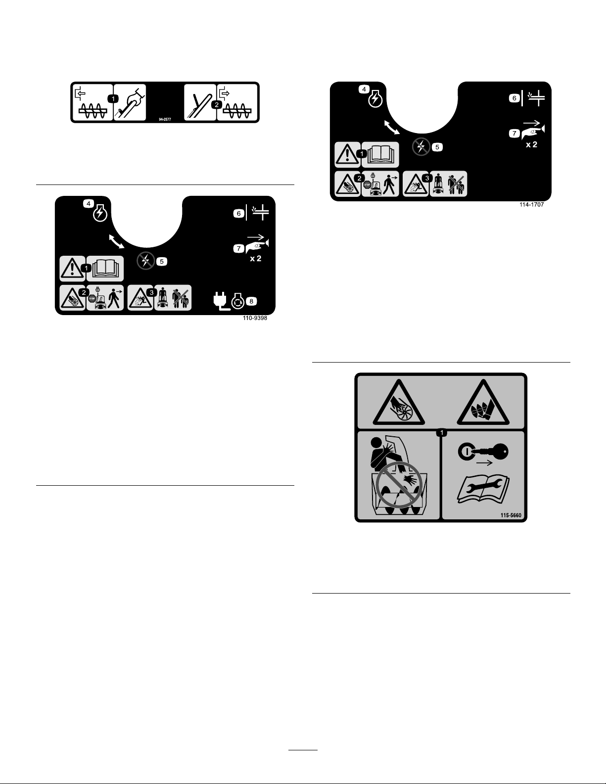
94-2577
1.Toengagetherotorblades,holdthecontrolbaragainst
thehandle.
2.Todisengagetherotorblades,releasethecontrolbar.
114-1707
Orderpartno.1 14-3752
1.Warning—readthe
Operator’sManual.
2.Cutting/dismemberment
hazard,impeller—stopthe
enginebeforeleavingthe
machine.
3.Thrownobject
hazard—keepbystanders
asafedistancefromthe
machine.
4.EngineswitchOn
Orderpartno.108-4928
110-9398
5.EngineswitchOff
6.Primer
7.Pushtheprimertwiceto
primetheengine.
8.Plugthemachineinto
powertheelectricstarter .
1.Warning—readthe
Operator’sManual.
2.Cutting/dismemberment
hazard,rotorblades—stop
theenginebeforeleaving
themachine.
3.Thrownobject
hazard—keepbystanders
asafedistancefromthe
machine.
4.EngineswitchOn
5.EngineswitchOff
6.Primer
7.Pushtheprimertwiceto
primetheengine.
115-5660
1.Cuttingdismembermenthazards,impellerandauger—do
notplaceyourhandinthechute;removetheignitionkey
andreadtheinstructionsbeforeservicingorperforming
maintenance.
4
Page 5
Setup
LooseParts
Usethechartbelowtoverifythatallpartshavebeenshipped.
ProcedureDescription
1
2
Nopartsrequired
Dischargechute1
Chutehandle
Phillipsheadscrews3
Washers3
Locknuts3
1
UnfoldingtheHandle
NoPartsRequired
Procedure
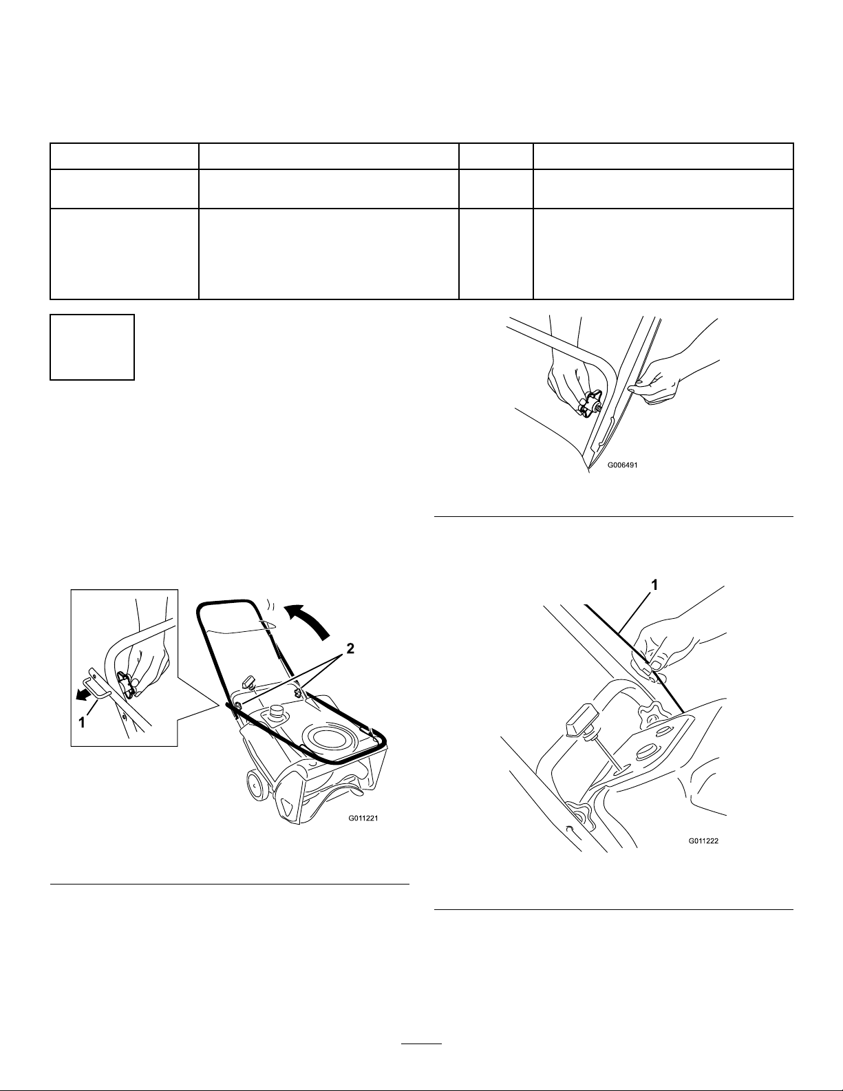
1.Loosenthehandleknobs,pulloutthe“U”-shaped
handlelocksuntilyoucanmovethehandlefreely,
androtatethehandletotheoperatingposition
Figure4).
(
Qty.
–
1
Important:Ensurethatyoudonotpinchor
kinkthecontrolcable(Figure6).
Unfoldthehandle.
Installthedischargechute.
Figure5
Use
Figure4
1.“U”-shapedhandlelock(2)
2.Inserttheendofthe“U”-shapedhandlelockinto
theopenholeinthehandleandtightenthehandle
knobsuntiltheyaresnug(
2.Handleknobs
Figure5).
Figure6
1.Controlcable
5
Page 6
2
3
InstallingtheDischargeChute
Partsneededforthisprocedure:
1Dischargechute
1
Chutehandle
3Phillipsheadscrews
3Washers
3Locknuts
Procedure
Installthedischargechuteasshown(Figure7).
AdjustingtheControlCable
NoPartsRequired
Procedure
RefertoAdjustingtheControlCableinMaintenance.
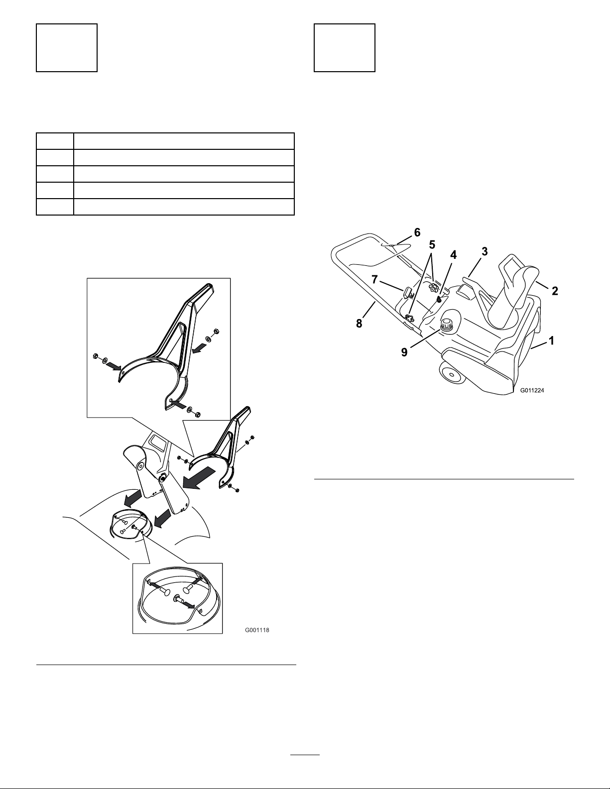
ProductOverview
Figure7
Figure8
1.Rotorblades
2.ChuteDeector
3.Dischargechutehandle8.Handle
4.Ignitionkey9.Fueltankcap
5.Handleknobs
6.Controlbar
7.Recoilstarthandle
6
Page 7
Operation
Note:Determinetheleftandrightsidesofthemachine
fromthenormaloperatingposition.
DANGER
50:1Gasoline-to-OilRatioMixingChart
GasolineOil
1.5USgallons(5.7liters)4.0ounces(120ml)
2USgallons(7.6liters)5.2ounces(160ml)
3USgallons(1 1.4liters)8.0ounces(240ml)
Gasolineisextremelyammableandexplosive.A
reorexplosionfromgasolinecanburnyouand
others.
•Topreventastaticchargefromignitingthe
gasoline,placethecontainerand/ormachine
onthegroundbeforelling,notinavehicleor
onanobject.
•Fillthetankoutdoorswhentheengineiscold.
Wipeupspills.
•Donothandlegasolinewhensmokingoraround
anopenameorsparks.
•Storegasolineinanapprovedfuelcontainer,out
ofthereachofchildren.
MixingGasolineandOil
Thismachineusesa50:1gasoline-to-oilmixture.Use
Toro50:12-CycleOil(FuelStabilizerAdded)oran
equivalenthigh-grade,NMMATCW3-certied2-cycle
oil.
3.Installthecaponthefuelcontainer.
4.Shakethecontainertomixthegasolineandoil
thoroughly.
5.Slowlyremovethecapandaddtheremaining
amountofgasoline.
Note:Donotmixgasolineandoilinthefueltank.
Oilatroomtemperaturemixeseasierandmore
thoroughlythancoldoil.Oilbelow32°F(0°C)
requiresadditionalmixing.
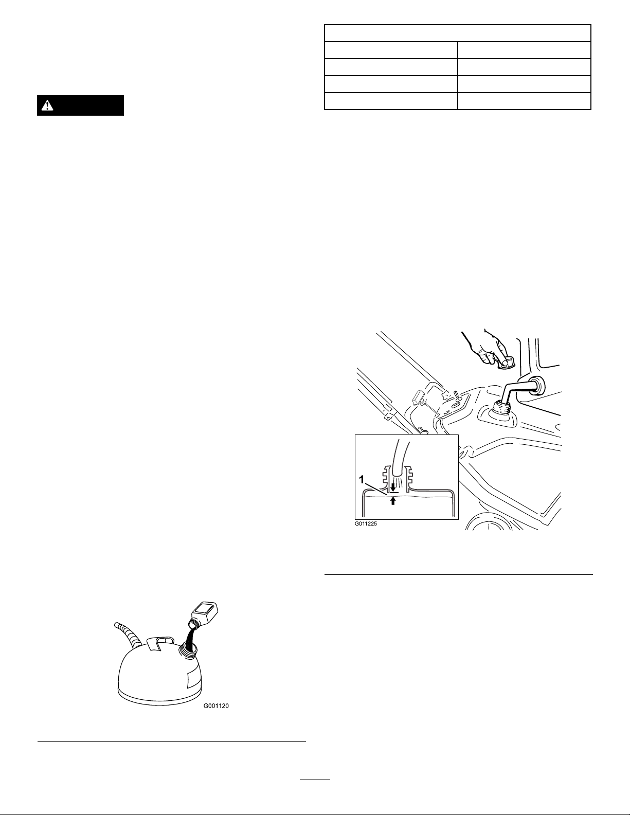
FillingtheFuelTank
Fillthefueltankwithfreshfuel(Figure10).
Important:DonotuseE85orE20fuel.Alternative
fuelswithhighalcoholcontentcancausehard
starting,poorengineperformance,andmaycause
internalenginedamage.
Important:Topreventenginedamage,donotuse
automotiveoil(suchasSAE30or10W30)orfuel
mixedatthewronggasoline-to-oilratio.
1.PourahalfUSgallon(1.9liters)offresh,unleaded
gasolineintoanapprovedfuelcontainer.
2.Add2-cycleoiltothegasoline(
tothefollowingchart:
Figure9
Figure9)according
Figure10
1.1/4inch(6mm)
7
Page 8

StartingtheEngine
1.TurntheignitionkeyclockwisetotheOnposition
(Figure11).
Figure14
Figure11
2.Movethechokelevertotheright(Figure12and
Figure13).
Figure12
1.Chokelever
Note:Removeyourglovewhenyoupushinthe
primersothataircannotescapefromtheprimer
hole.
Important:Donotusetheprimerorthe
chokeiftheenginehasbeenrunningasishot.
Excessiveprimingmayoodtheengineand
preventitfromstarting.
4.Connectagroundedextensioncordtoapower
sourceandthemachine,andpushtheelectric-start
button(model38593only)(
Figure15),orpullthe
recoilstarthandle(Figure16).
Figure13
1.Symbolsonthechokeleverindicatingtomovethechoke
levertotherighttoactivatethechoke.
3.Firmlypushintheprimer2timeswithyourthumb,
holdingtheprimerinaforasecondbeforereleasing
iteachtime(Figure14).
Figure15
1.Electric-startbutton
Note:UseonlyaUL-listed,16-gaugeextension
cordrecommendedforoutdoorusethatisnot
longerthan50feet(15m).
8
Page 9

WARNING
Theelectricalcordcanbecomedamaged,
causingashockorre.
Thoroughlyinspecttheelectricalcordbefore
pluggingitintoapowersource.Ifthe
cordisdamaged,donotuseittostartthe
machine.Replaceorrepairthedamagedcord
immediately.ContactanAuthorizedService
Dealerforassistance.
Figure17
1.Controlbar
DisengagingtheRotorBlades
Todisengagetherotorblades,releasethecontrolbar
(Figure18).
Figure16
Important:Runtheelectricstarternomore
than10timesatintervalsof5secondson,then
5secondsoff.Runningtheelectricstarter
extensivelycanoverheatanddamageit.Ifthe
enginedoesnotstartafterthisseriesofattempts,
waitatleast40minutestoallowthestarterto
coolbeforeattemptingtostartitagain.Ifthe
enginedoesnotstartafterthesecondseriesof
attempts,takethemachinetoanAuthorized
ServiceDealerforservice(model38593only).
Note:Ifyoupulltherecoilhandleandfeelno
resistance,thestartermaybefrozen.Thawoutthe
starterbeforeattemptingtostartthemachine.
5.Whiletheengineisrunning,movethechokeleverto
theleftslowly.
6.Unplugtheextensioncordfromthepowersource
andthemachine(model38593only).
Figure18
StoppingtheEngine
Tostoptheengine,turntheignitionkey
counterclockwisetotheOffposition(Figure19).
EngagingtheRotorBlades
Toengagetherotorblades,holdthecontrolbaragainst
thehandle(Figure17).
Figure19
9
Page 10

AdjustingtheDischargeChute
Toadjustthedischargechute,movethechutehandle
andthechutedeectorhandleasshown(Figure20).
whentryingtooperatefrozencontrols.Ifyouhave
difcultyoperatinganycontrolorpart,startthe
engineandletitrunforafewminutes.
OperatingTips
WARNING
Therotorbladescanthrowstones,toys,andother
foreignobjectsandcauseseriouspersonalinjuryto
theoperatorortobystanders.
•Keeptheareatobeclearedfreeofallobjects
thattherotorbladescouldpickupandthrow.
Figure20
1.Chutehandle2.Chutedeectorhandle
ClearingaCloggedDischarge
Chute
Important:Handcontactwiththerotating
rotorbladesinsidethedischargechuteisthe
mostcommoncauseofinjuryassociatedwith
snowthrowers.Neveruseyourhandtocleanout
thedischargechute.
Toclearthechute:
•Shuttheengineoff!
•Wait10secondstobesurethattherotorbladeshave
stoppedrotating.
•Alwaysuseaclean-outtool,notyourhands.
PreventingFreeze-upafter
Use
•Lettheenginerunforafewminutestoprevent
movingpartsfromfreezing.Stoptheengine,wait
forallmovingpartstostop,andremoveiceand
snowfromthemachine.
•Cleanoffanysnowandicefromthebaseofthe
chute.
•Rotatethedischargechuteleftandrighttofreeit
fromanyicebuildup.
•WiththeignitionkeyintheOffposition,pull
therecoilstarterhandleseveraltimesorpushthe
electric-startbuttononce(model38593only)to
preventtherecoilandelectricstartersfromfreezing
up.
•Insnowyandcoldconditions,somecontrolsand
movingpartsmayfreeze.Donotuseexcessiveforce
•Keepallchildrenandpetsawayfromthearea
ofoperation.
•Removethesnowassoonaspossibleafteritfalls.
•Ifthemachinedoesnotpropelitselfforwardon
slipperysurfacesorinheavysnow,pushforwardon
thehandle,butallowthemachinetoworkatitsown
pace.
•Overlapeachswathtoensurecompletesnow
removal.
•Dischargethesnowdownwindwheneverpossible.
•Iftheengineisrunningnormallybutthemachine
doesnotthrowsnowasfarasitusuallydoes,
performthefollowingstepsasneededuntilthe
problemissolved:
1.Checkthecontrolcableadjustmentandadjustit
ifnecessary;refertoAdjustingtheControlCable.
2.Inspecttherotorbladesforexcessivewear(refer
toCheckingtheRotorBlades),andhavean
AuthorizedDealerreplacethemifnecessary.
3.Replacethedrivebelt;refertoReplacingthe
DriveBelt.
4.Ifnoneoftheprocedureslistedabovesolvesthe
problem,contactanAuthorizedServiceDealer.
10
Page 11

Maintenance
Note:Determinetheleftandrightsidesofthemachinefromthenormaloperatingposition.
RecommendedMaintenanceSchedule(s)
MaintenanceService
Interval
Afterthersthour
Yearly
Yearlyorbeforestorage
MaintenanceProcedure
•Checkthecontrolcableandadjustitifnecessary.
•Checkforloosefastenersandtightenthemifnecessary.
•Checkthecontrolcableandadjustitifnecessary.
•InspecttherotorbladesandhaveanAuthorizedServiceDealerreplacetherotor
bladesandscraperifnecessary.
•Servicethesparkplugandreplaceitifnecessary.
•Checkforloosefastenersandtightenthemifnecessary.
•HaveanAuthorizedServiceDealerinspectthedrivebeltandreplaceitifnecessary.
•Preparethemachineforstorage.
AdjustingtheControlCable
CheckingtheControlCable
ServiceInterval:Afterthersthour—Check
thecontrolcableandadjustitif
necessary.
Yearly—Checkthecontrolcableand
adjustitifnecessary.
Note:Ensurethata1/16-inchto1/8-inch(2mmto3
mm)gapexistsbetweenthecontrolbarandthehandle
(Figure21).
Important:Thecontrolcablemustcontainsome
slackwhenyoudisengagethecontrolbarforthe
rotorbladestostopproperly.
AdjustingtheControlCable
Movethecontrolbarbacktowardthehandletoremove
theslackinthecontrolcable(
Figure21
1.Controlbar2.1/16-inchto1/8-inch(2
Figure21).
mmto3mm)gap
1.Slideupthespringcoverandunhookthespring
fromtheadjusterlink(Figure22).
Figure22
1.Adjusterlink
2.Z-tting
3.Springcover
4.Unhookthespringhere.
Note:Youcanpulluptheadjusterlinkandcableto
makeunhookingthespringeasier.
11
Page 12

2.MovetheZ-ttingtoahigherorlowerholeonthe
adjusterlinkasneededtoobtainthe1/16-inchto
1/8-inch(2mmto3mm)gapbetweenthecontrol
barandthehandle(
Figure22).
Note:MovingtheZ-ttinghigherdecreasesthe
gapbetweenthecontrolbarandthehandle;moving
itlowerincreasesthegap.
3.Hookthespringtotheadjusterlinkandslidethe
springcoverovertheadjusterlink.
4.Checktheadjustment;refertoCheckingtheControl
Cable.
Note:Afterextendeduse,thedrivebeltmaywear
andloseitsproperbelttension.Ifthedrivebelt
slips(continuouslysqueals)underaheavyload,
disconnectthespringfromtheadjustorlinkand
movetheupperendofthespringtotheholethat
isfurtherfromthepivotpointinthecontrolbar
Figure23).Thenconnectthespringtotheadjustor
(
linkandadjustthecontrolcable.
InspectingtheRotorBlades
ServiceInterval:Yearly—Inspecttherotorbladesand
haveanAuthorizedServiceDealer
replacetherotorbladesandscraperif
necessary.
Beforeeachsession,inspecttherotorbladesforwear.
Whenarotorbladeedgehasworndowntothewear
indicatorhole,haveanAuthorizedServiceDealer
replacetherotorbladesandthescraper(
Figure24).
1.Upperendofspring
2.Inserttheupperendof
springintothishole
Figure23
3.Pivotpoint
4.Removetheupperendof
springfromthishole
Figure24
1.Wearindicatorhole
ServicingtheSparkPlug
ServiceInterval:Yearly—Servicethesparkplugand
replaceitifnecessary.
UseaNGKBPMR4Asparkplugorequivalent.
1.Stoptheengineandwaitforallmovingpartstostop.
2.Rotatethedischargechutesothatitfacesforward.
3.Removethedischargechute;refertothegurein
InstallingtheDischargeChuteprocedureinthe
Setupsection.
4.Removethe4screwsthatsecuretheshroud
(Figure25).
Note:Thebeltmayslip(squeal)inwetconditions;
todryoutthedrivesystem,starttherotorandrun
itwithoutaloadfor30seconds.
12
Page 13

12.Installthesparkplugandtightenitsecurely.
13.Connectthewiretothesparkplug.
14.Removethefueltankcap.
15.Installtheshroudwiththescrewsyouremovedin
4.
step
Note:Ensurethattheupperandlowershroudst
togetherinthesidegrooves.
16.Installthefueltankcap.
17.Installthechuteseal,thedischargechute,andthe
dischargechutehandleontothemachineusingthe
hardwareyouremovedinstep
3.
Note:Thesmallscrewgoesthroughthesmallhole
inthechutesealatthefrontofthedischargechute
opening.
ReplacingtheDriveBelt
Figure25
1.Screw(4)3.Spark-plugwire
2.Shroud
5.Removethefueltankcap.
6.Removetheshroud(
Figure25).
7.Installthefueltankcap.
8.Disconnectthewirefromthesparkplug.
9.Cleanaroundthesparkplug.
10.Removethesparkplugfromthecylinderhead.
Important:Replaceacracked,fouled,or
dirtysparkplug.Donotcleantheelectrodes
becausegritenteringthecylindercandamage
theengine.
11.Setthegapontheplugto0.030inch(0.76mm)
Figure26).
(
Ifdrivebeltbecomesworn,oil-soaked,excessively
cracked,frayed,orotherwisedamaged,replacethebelt.
1.Removethedrivebeltcoverbyremovingthe3bolts
asshowninFigureFigure27.
Figure27
1.Drivebeltcover6.Drivebelt
2.Bolt(3)7.Rotorshaft
3.Rotorpulleybolt
4.Curvedwasher
5.Rotorpulley10.Enginepulley
8.Brakespring(unhookfrom
idlerarmhere)
9.Idlerpulley
Figure26
1.Centerelectrodeinsulator3.Airgap(nottoscale)
2.Sideelectrode
2.Unhookthebrakespringfromtheidlerarmto
releasethebelttension(Figure27).
3.Removethescrewandcurvedwasherthatholdthe
rotorpulley(Figure27).
13
Page 14

4.Removetherotorpulleyandthedrivebelt
(Figure27).
Storage
5.Installthenewdrivebelt,routingitasshownin
Figure28.
Figure28
1.Brakespring(installon
idlerarmhere)
2.Idlerpulley4.Rotorpulley
Note:Routethenewdrivebeltrstaroundthe
enginepulley,thentheidlerpulley,andnallyaround
thelooserotorpulleypositionedjustabovetherotor
Figure27).
shaft(
6.Installtherotorpulleyontotherotorshaft
(Figure27).
7.Installthecurvedwasherandtherotorpulleybolt
andtightenthemsecurely(Figure27).
Note:Theconcavesideofthecurvedwashergoes
againsttheoutsideofthepulley.
8.Installthebrakespringontotheidlerarm(
9.Installthedrivebeltcoverwiththeboltsyou
removedinstep1.
Note:Ensurethatthedrivebeltisproperlyadjusted
andoperating;refertoCheckingtheControlCable
andAdjustingtheControlCable.
3.Enginepulley
Figure28).
StoringtheMachine
WARNING
•Gasolinefumesarehighlyammable,explosive,
anddangerousifinhaled.Ifyoustorethe
machineinanareawithanopename,the
gasolinefumesmayigniteandcausean
explosion.
•Donotstorethemachineinahouse(living
area),basement,oranyotherareawhereignition
sourcesmaybepresent,suchashotwaterand
spaceheaters,clothesdryers,furnaces,and
otherlikeappliances.
Important:Donotusethechutehandletoliftthe
machine.Thiscandamagethechutehandle.
1.Addafuelstabilizer/conditionertothefuelinthe
fueltankasdirectedbytheenginemanufacturer.
2.Runtheenginefor5minutestodistributethe
conditionedfuelthroughthefuelsystem.
3.Stoptheengineandallowittocool.
4.Useahandpumptopumpthefuelfromthefuel
tankintoanapprovedfuelcontainer,orrunthe
engineuntilitstops.
5.Starttheengineandrunituntilitstops.
6.Chokeorprimetheengine,startitathirdtime,and
runtheengineuntilitwillnotstart.
7.Slowlypulltherecoilstarteruntilyoufeelresistance
duetocompressionpressure,thenstop.
8.Releasethestartertensiongraduallybyallowingthe
ropetogobackslowlytopreventtheenginefrom
thereversingduetocompressionpressure.
9.Disposeofunusedfuelproperly.Recycleit
accordinglytolocalcodes,oruseitinyour
automobile.
Note:Donotstorestabilizedfuelformorethan
90days.
10.Cleanthemachine.
11.Tightenanyloosefasteners.Repairorreplaceany
damagedparts.
12.Coverthemachineandstoreitinaclean,dryplace
outofthereachofchildren.Allowtheengineto
coolbeforestoringitinanyenclosure.
14
Page 15

Notes:
15
Page 16

TheToro2-YearGTSStartingGuaranteeand
TheToroT otalCoverageGuarantee
AT wo-YearFullWarranty(45DayLimitedWarrantyforCommercialUse)
CCR
PowerClear
Single-StageSnowthrowers
TheToroStartingGuarantee
TheT oroCompanyanditsafliate,ToroWarrantyCompany,pursuant
toanagreementbetweenthem,jointlyguaranteethatyourT oroGTS
(GuaranteedtoStart)engine,whenusedforresidentialpurposes*,will
startontherstorsecondpullfortwo(2)yearsfromthedateofpurchase,
ifyouprovidetheroutinemaintenanceitrequires,orwewillxitfreeof
charge.
Thiswarrantycoversthecostofpartsandlabor ,butyoumustpay
transportationcosts.
ConditionsandProductsCovered
TheToroCompanyanditsafliate,T oroWarrantyCompany,pursuantto
anagreementbetweenthem,jointlypromisetorepairtheT oroProduct
listedbelowifusedforresidentialpurposes*,ifdefectiveinmaterialsor
workmanshiporifitstopsfunctioningduetothefailureofacomponent
fortheperiodlistedbelow.
Thiswarrantycoversthecostofpartsandlabor ,butyoumustpay
transportationcosts.
Thefollowingtimeperiodsapplyfromthedateofpurchase:
ProductsWarrantyPeriod
PowerClearSnowthrowersandAttachments
2years
LimitedWarrantyforCommercialUse
Gas-poweredT oroProductsusedforcommercial,institutional,or
rentaluse,arewarrantedfor45daysagainstdefectsinmaterialsor
workmanship.Componentsfailingduetonormalweararenotcovered
bythiswarranty.
InstructionsforObtainingWarrantyService
IfyouthinkthatyourT oroProductcontainsadefectinmaterialsor
workmanship,followthisprocedure:
1.ContactanyAuthorizedT oroServiceDealertoarrangeserviceattheir
dealership.Tolocateadealerconvenienttoyou,refertotheYellow
Pagesofyourtelephonedirectory(lookunder“LawnMowers”)or
accessourwebsiteatwww.Toro.com.Youmayalsocallthenumbers
listedinitem#3tousethe24-hourT oroDealerlocatorsystem.
2.Bringtheproductandyourproofofpurchase(salesreceipt)tothe
ServiceDealer.Thedealerwilldiagnosetheproblemanddetermine
ifitiscoveredunderwarranty.
3.IfforanyreasonyouaredissatisedwiththeServiceDealer’s
analysisorwiththeassistanceprovided,contactusat:
CustomerCareDepartment,ConsumerDivision
TheT oroCompany
811 1LyndaleAvenueSouth
Bloomington,MN55420-1196
Tollfreeat866-336-5205(U.S.customers)
Tollfreeat866-854–9033(Canadiancustomers)
OwnerResponsibilities
YoumustmaintainyourT oroProductbyfollowingthemaintenance
proceduresdescribedintheOperator’sManual.Suchroutine
maintenance,whetherperformedbyadealerorbyyou,isatyourexpense.
ItemsandConditionsNotCovered
Thereisnootherexpresswarrantyexceptforspecialemissionsystem
coverageandenginewarrantycoverageonsomeproducts.Thisexpress
warrantydoesnotcoverthefollowing:
•Costofregularmaintenanceorwearparts,suchasrotorblades
(paddles),scraperblades,belts,fuel,lubricants,oilchanges,spark
plugs,cable/linkageorbrakeadjustments
•Anyproductorpartwhichhasbeenalteredormisusedandrequires
replacementorrepairduetoaccidentsorlackofpropermaintenance
•Repairsnecessaryduetofailuretousefreshfuel(lessthanone
monthold),orfailuretoproperlypreparetheunitpriortoanyperiod
ofnon-useoveronemonth
•Pickupanddeliverycharges
•Operationalmisuse,neglect,oraccidents
•RepairsorattemptedrepairsbyanyoneotherthananAuthorized
ToroServiceDealer
•Repairsoradjustmentstocorrectstartingdifcultiesduetothe
following:
–failuretofollowpropermaintenanceprocedures
–snowthrowerauger/paddlesstrikinganobject
–contaminantsinthefuelsystem
–improperfuelorfuel/oilmixture(consultyourOperator’sManual
ifindoubt)
–failuretodrainthefuelsystempriortoanyperiodofnon-use
overonemonth
•Specialoperationalconditionswherestartingmayrequiremorethan
twopulls:
–rsttimestartsafterextendedperiodofnon-useoverthree
monthsorseasonalstorage
–improperstartingprocedures
–startingin-10°F(-23°C)orbelowtemperatures
Ifyouarehavingdifcultystartingyourunit,pleasechecktheOperator’s
Manualtoensurethatyouareusingthecorrectstartingprocedures.This
cansaveanunnecessaryvisittoaServiceDealer .
GeneralConditions
Allrepairscoveredbythesewarrantiesmustbeperformedbyan
AuthorizedToroServiceDealerusingT oroapprovedreplacementparts.
RepairbyanAuthorizedToroServiceDealerisyoursoleremedyunder
thiswarranty .
NeitherTheT oroCompanynorToroWarrantyCompanyisliablefor
indirect,incidental,orconsequentialdamagesinconnectionwiththe
useoftheT oroProductscoveredbythesewarranties,includingany
costorexpenseofprovidingsubstituteequipmentorserviceduring
reasonableperiodsofmalfunctionornon-usependingcompletionof
repairsunderthesewarranties.
Somestatesdonotallowexclusionsofincidentalorconsequential
damages,sotheaboveexclusionsmaynotapplytoyou.
Thiswarrantygivesyouspeciclegalrights,andyoumayalsohaveother
rightswhichvaryfromstatetostate.
CountriesOtherthantheUnitedStatesorCanada
CustomerswhohavepurchasedT oroproductsexportedfromtheUnitedStatesorCanadashouldcontacttheirT oroDistributor(Dealer)toobtain
guaranteepoliciesforyourcountry,province,orstate.IfforanyreasonyouaredissatisedwithyourDistributor’sserviceorhavedifcultyobtaining
guaranteeinformation,contacttheToroimporter .Ifallotherremediesfail,youmaycontactusatT oroWarrantyCompany.
*Residentialpurposesmeansuseoftheproductonthesamelotasyourhome.Useatmorethanonelocation,orinstitutionalorrentaluse,isconsidered
commercialuse,andthecommercialusewarrantywouldapply .
374-0264RevB
 Loading...