

Page 1
FormNo.3358-435RevB
PowerClear™Snowthrower
ModelNo.38585—SerialNo.280000001andUp
ModelNo.38586—SerialNo.280000001andUp
Operator'sManual
Introduction
Readthisinformationcarefullytolearnhowtooperate
andmaintainyourproductproperlyandtoavoidinjury
andproductdamage.Youareresponsibleforoperating
theproductproperlyandsafely.
YoumaycontactTorodirectlyatwww.Toro.comfor
productandaccessoryinformation,helpndinga
dealer,ortoregisteryourproduct.
Wheneveryouneedservice,genuineToroparts,or
additionalinformation,contactanAuthorizedService
DealerorToroCustomerServiceandhavethemodel
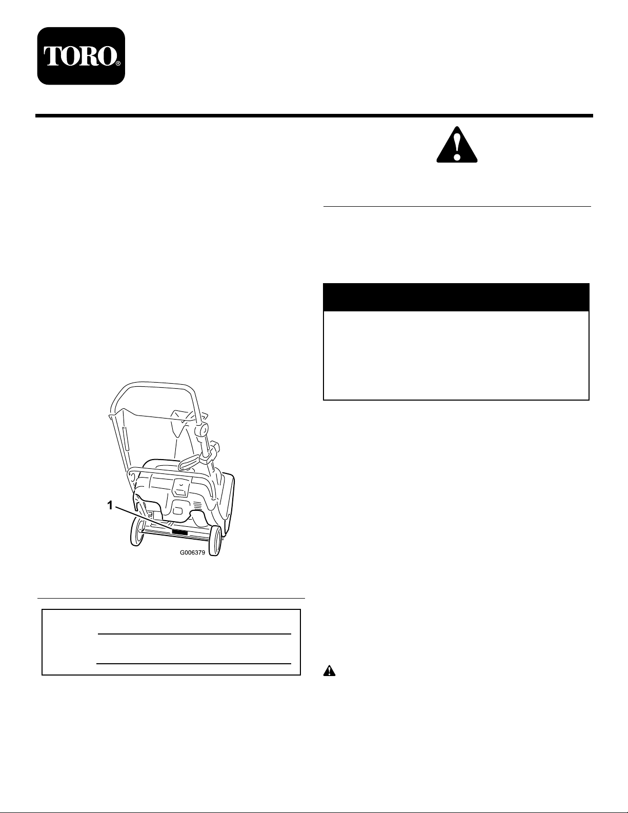
andserialnumbersofyourproductready.Figure1
identiesthelocationofthemodelandserialnumbers
ontheproduct.Writethenumbersinthespace
provided.
Figure2
1.Safetyalertsymbol
Thismanualuses2wordstohighlightinformation.
Importantcallsattentiontospecialmechanical
informationandNoteemphasizesgeneralinformation
worthyofspecialattention.
Warning
CALIFORNIA
Proposition65Warning
Theengineexhaustfromthisproduct
containschemicalsknowntotheStateof
Californiatocausecancer,birthdefects,
orotherreproductiveharm.
ThissparkignitionsystemcomplieswithCanadian
ICES-002.
Theenclosed
forinformationregardingtheUSEnvironmental
ProtectionAgency(EPA)andtheCalifornia
EmissionControlRegulationofemissionsystems,
maintenance,andwarranty.Replacementsmaybe
orderedthroughtheenginemanufacturer.
Engine Owner’ s Man ual
issupplied
Figure1
1.Modelandserialnumberlocation
ModelNo.
SerialNo.
Thismanualidentiespotentialhazardsandhas
safetymessagesidentiedbythesafetyalertsymbol
(Figure2),whichsignalsahazardthatmaycauseserious
injuryordeathifyoudonotfollowtherecommended
precautions.
©2008—TheT oro®Company
8111LyndaleAvenueSouth
Bloomington,MN55420
Registeratwww.Toro.com.
Safety
ThissnowthrowermeetsorexceedstheB71.3
specicationsoftheAmericanNationalStandards
Instituteineffectatthetimeofproduction.
Readandunderstandthecontentsofthismanual
beforeyoustarttheengine.
Thisisthesafetyalertsymbol.Itisusedtoalert
youtopotentialpersonalinjuryhazards.Obeyall
safetymessagesthatfollowthissymboltoavoid
possibleinjuryordeath.
Improperlyusingormaintainingthissnowthrower
couldresultininjuryordeath.Toreducethis
OriginalInstructions(EN)
PrintedintheUSA
AllRightsReserved
Page 2

potential,complywiththefollowingsafety
instructions.
–Iffuelisspilledonclothing,changeclothing
immediately.
Thissnowthroweriscapableofamputatinghands
andfeetandofthrowingobjects.Failuretoobserve
thefollowingsafetyinstructionscouldresultin
seriousinjury.
Training
•Read,understand,andfollowallinstructionsonthe
machineandinthemanual(s)beforeoperatingthis
unit.Bethoroughlyfamiliarwiththecontrolsand
theproperuseoftheequipment.Knowhowtostop
theunitanddisengagethecontrolsquickly .
•Neverallowchildrentooperatetheequipment.
Neverallowadultstooperatetheequipmentwithout
properinstruction.
•Keeptheareaofoperationclearofallpersons,
particularlysmallchildren.
•Exercisecautiontoavoidslippingorfalling.
Preparation
•Thoroughlyinspecttheareawheretheequipmentis
tobeusedandremovealldoormats,sleds,boards,
wires,andotherforeignobjects.
•Donotoperatetheequipmentwithoutwearing
adequatewintergarments.Avoidloosetting
clothingthatcangetcaughtinmovingparts.Wear
footwearthatwillimprovefootingonslippery
surfaces.
•Handlefuelwithcare;itishighlyammable.
–Useanapprovedfuelcontainer.
–Neveraddfueltoarunningengineorhotengine.
–Fillfueltankoutdoorswithextremecare.Never
llfueltankindoors.
–Neverllcontainersinsideavehicleorona
truckortrailerbedwithaplasticliner.Always
placecontainersontheground,awayfromyour
vehicle,beforelling.
–Whenpractical,removegas-poweredequipment
fromthetruckortrailerandrefuelitonthe
ground.Ifthisisnotpossible,thenrefuelsuch
equipmentonatrailerwithaportablecontainer,
ratherthanfromagasolinedispensernozzle.
–Keepthenozzleincontactwiththerimof
thefueltankorcontaineropeningatalltimes,
untilrefuelingiscomplete.Donotuseanozzle
lock-opendevice.
–Replacegasolinecapsecurelyandwipeupspilled
fuel.
•Useextensioncordsandreceptaclesasspeciedby
themanufacturerforallunitswithelectricstarting
motors.
•Donotattempttoclearsnowfromagravelor
crushedrocksurface.Thisproductisintendedfor
useonlyonpavedsurfaces.
•Neverattempttomakeanyadjustmentswhile
theengineisrunning(exceptwhenspecically
recommendedbymanufacturer).
•Alwayswearsafetyglassesoreyeshieldsduring
operationorwhileperforminganadjustmentor
repairtoprotecteyesfromforeignobjectsthatmay
bethrownfromthemachine.
Operation
•Donotputhandsorfeetnearorunderrotatingparts.
Keepclearofthedischargeopeningatalltimes.
•Exerciseextremecautionwhenoperatingonor
crossinggraveldrives,walks,orroads.Stayalertfor
hiddenhazardsortrafc.
•Afterstrikingaforeignobject,stoptheengine,
removetheignitionkey,thoroughlyinspectthesnow
throwerforanydamage,andrepairthedamage
beforerestartingandoperatingthesnowthrower.
•Iftheunitshouldstarttovibrateabnormally,stop
theengineandcheckimmediatelyforthecause.
Vibrationisgenerallyawarningoftrouble.
•Stoptheenginewheneveryouleavetheoperating
position,beforeuncloggingtherotorbladehousing
ordischargechute,andwhenmakinganyrepairs,
adjustmentsorinspections.
•Whencleaning,repairing,orinspectingthesnow
thrower,stoptheengineandmakecertainthatthe
rotorbladesandallmovingpartshavestopped.
•Donotruntheengineindoors,exceptwhenstarting
theengineandfortransportingthesnowthrower
inoroutofthebuilding.Opentheoutsidedoors;
exhaustfumesaredangerous.
•Exerciseextremecautionwhenoperatingonslopes.
•Neveroperatethesnowthrowerwithoutproper
guardsandothersafetyprotectivedevicesinplace
andworking.
•Neverdirectthedischargetowardpeopleorareas
wherepropertydamagecanoccur.Keepchildren
andothersaway.
•Donotoverloadthemachinecapacitybyattempting
toclearsnowattoofastarate.
2
Page 3

•Lookbehindandusecarewhenbackingupwiththe
snowthrower.
•Disengagepowertotherotorbladeswhensnow
throweristransportedornotinuse.
•Neveroperatethesnowthrowerwithoutgood
visibilityorlight.Alwaysbesureofyourfooting,and
keeparmholdonthehandles.Walk;neverrun.
•Nevertouchahotengineormufer.
ClearingaCloggedDischarge
Chute
Handcontactwiththerotatingrotorbladesinsidethe
dischargechuteisthemostcommoncauseofinjury
associatedwithsnowthrowers.Neveruseyourhandto
cleanoutthedischargechute.
Toclearthechute:
•Shuttheengineoff!
•Wait10secondstobesuretherotorbladeshave
stoppedrotating.
•Alwaysuseaclean-outtool,notyourhands.
ToroSnowthrowerSafety
Thefollowinglistcontainssafetyinformationspecic
toToroproductsorothersafetyinformationthatyou
mustknow.
•Rotatingrotorbladescaninjurengersor
hands.Staybehindthehandlesandawayfromthe
dischargeopeningwhileoperatingthesnowthrower.
Keepyourface,hands,feet,andanyotherpart
ofyourbodyorclothingawayfrommovingor
rotatingparts.
•Beforeadjusting,cleaning,repairing,andinspecting
thesnowthrower,andbeforeuncloggingthe
dischargechute,stoptheengine,removethekey,
andwaitforallmovingpartstostop.
•Beforeleavingtheoperatingposition,stopthe
engine,removetheignitionkey,andwaitforall
movingpartstostop.
•Ifashield,safetydevice,ordecalisdamaged,
illegible,orlost,repairorreplaceitbeforebeginning
operation.Also,tightenanyloosefasteners.
•Donotsmokewhilehandlinggasoline.
•Donotusethesnowthroweronaroof.
MaintenanceandStorage
•Checkallfastenersatfrequentintervalsforproper
tightnesstobesuretheequipmentisinsafeworking
condition.
•Neverstorethemachinewithfuelinthefueltank
insideabuildingwhereignitionsourcesarepresent,
suchashotwaterheaters,spaceheaters,orclothes
dryers.Allowtheenginetocoolbeforestoringin
anyenclosure.
•AlwaysrefertotheOperator’sManualforimportant
detailsifthesnowthroweristobestoredforan
extendedperiod.
•Maintainorreplacesafetyandinstructionlabels,as
necessary.
•Runthemachineafewminutesafterthrowingsnow
topreventfreeze-upoftherotorblades.
•Donottouchtheenginewhileitisrunningorsoon
afterithasstoppedbecausetheenginemaybehot
enoughtocauseaburn.
•Performonlythosemaintenanceinstructions
describedinthismanual.Beforeperformingany
maintenance,service,oradjustment,stoptheengine
andremovethekey.Ifmajorrepairsareeverneeded,
contactanAuthorizedServiceDealer.
•Donotchangethegovernorsettingsontheengine.
•Whenstoringthesnowthrowerformorethan30
days,drainthefuelfromthefueltanktoprevent
apotentialhazard.Storefuelinanapprovedfuel
container.Removethekeyfromtheignitionswitch
beforestoringthesnowthrower.
•PurchaseonlygenuineTororeplacementpartsand
accessories.
3
Page 4
SafetyandInstructionalDecals
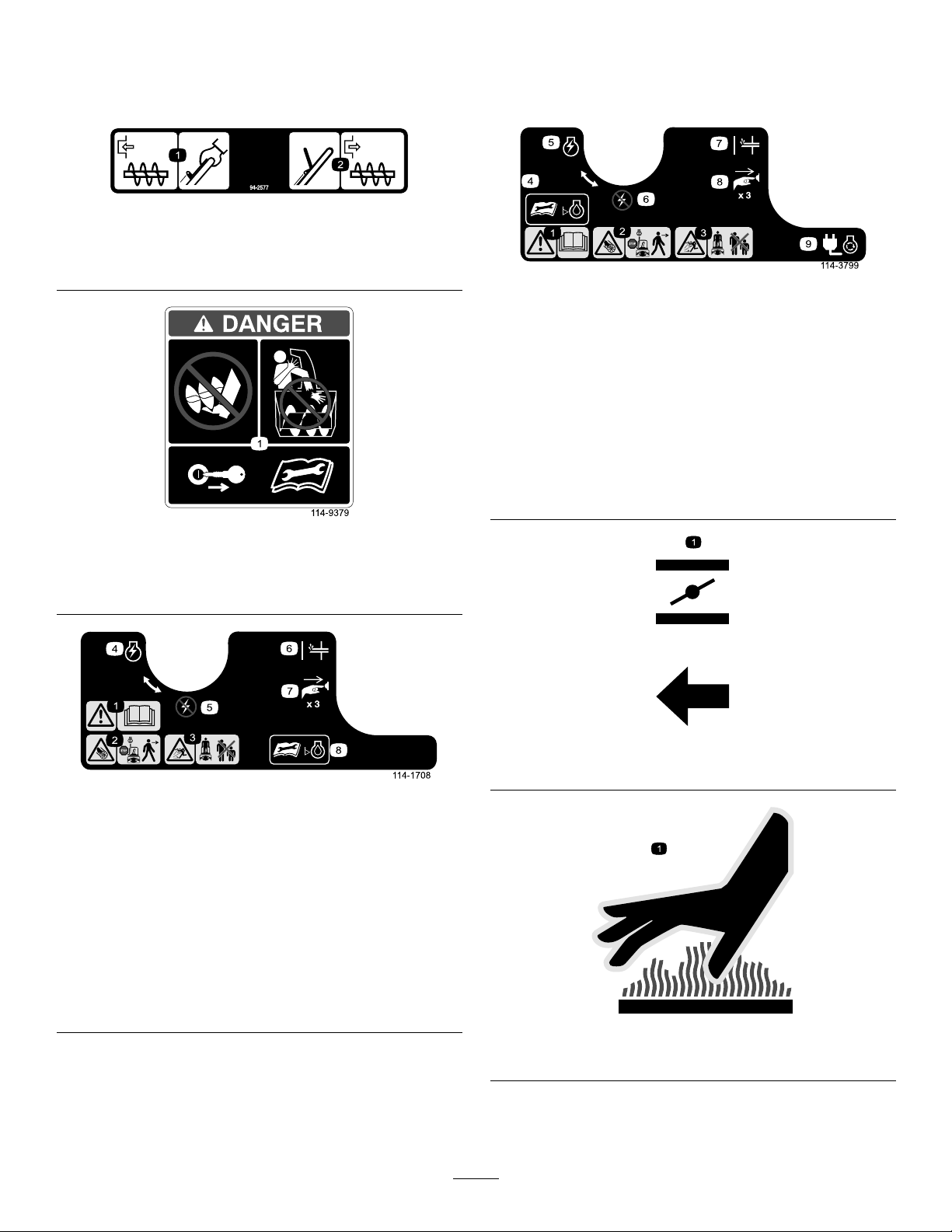
Important:Safetyandinstructiondecalsarelocatednearareasofpotentialdanger.Replacedamaged
decals.
94-2577
1.Toengagetherotorblades,holdthecontrolbaragainst
thehandle.
2.Todisengagetherotorblades,releasethecontrolbar.
114-3753(Model38586only)
1.Warning—readtheOperator’sManual.
2.Cutting/dismembermenthazard,rotorblades—stopthe
enginebeforeleavingthemachine.
3.Thrownobjecthazard—keepbystandersasafedistance
fromthemachine.
4.ReadtheOperator’sManualbeforecheckingengineoil
level.
5.EngineswitchOn
6.EngineswitchOff
7.Primer
8.Pushtheprimerthreetimestoprimetheengine.
9.Plugthemachineintopowertheelectricstarter.
108-4939
1.Cuttingdismemberment,rotorbladeshazard;donotplace
yourhandinthechute;removetheignitionkeyandreadthe
instructionsbeforeservicingorperformingmaintenance.
108-4930(Model38585only)
1.Warning—readthe
Operator’sManual.
2.Cutting/dismemberment
hazard,rotorblades—stop
theenginebeforeleaving
themachine.
3.Thrownobject
hazard—keepbystanders
asafedistancefromthe
machine.
4.EngineswitchOn8.ReadtheOperator’s
5.EngineswitchOff
6.Primer
7.Pushtheprimerthree
timestoprimetheengine.
Manualbeforechecking
engineoillevel.
110-9363
1.Choke
114-3794
1.Hotsurface(onexhaustbafe)
4
Page 5
Setup
LooseParts
Usethechartbelowtoverifythatallpartshavebeenshipped.
ProcedureDescription
1.
2.
Nopartsrequired
Screws
Chuteassembly
1.UnfoldingtheHandle
Procedure
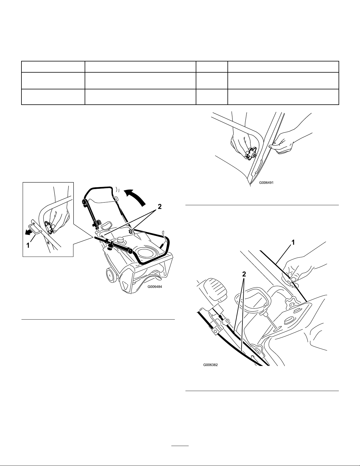
1.Loosenthehandleknobs,pulloutthe“U”-shaped
handlelocksuntilyoucanmovethehandlefreely ,
androtatethehandletotheoperatingposition
(Figure3).
Qty.
–
3
1
Unfoldthehandle.
Installthedischargechute.
Figure4
Use
Important:Ensurethatyoudonotpinchor
kinkthecontrolcableortheQuickShoot™
cables(Figure5).
Figure3
1.“U”-shapedhandlelock(2)
2.Handleknobs
2.Inserttheendofthe“U”-shapedhandlelockinto
theopenholeinthehandleandtightenthehandle
knobsuntiltheyaresnug(Figure4).
Figure5
1.Controlcable2.QuickShoot™cables
5
Page 6
2.InstallingtheDischarge
Chute
3
Screws
1
Chuteassembly
Procedure
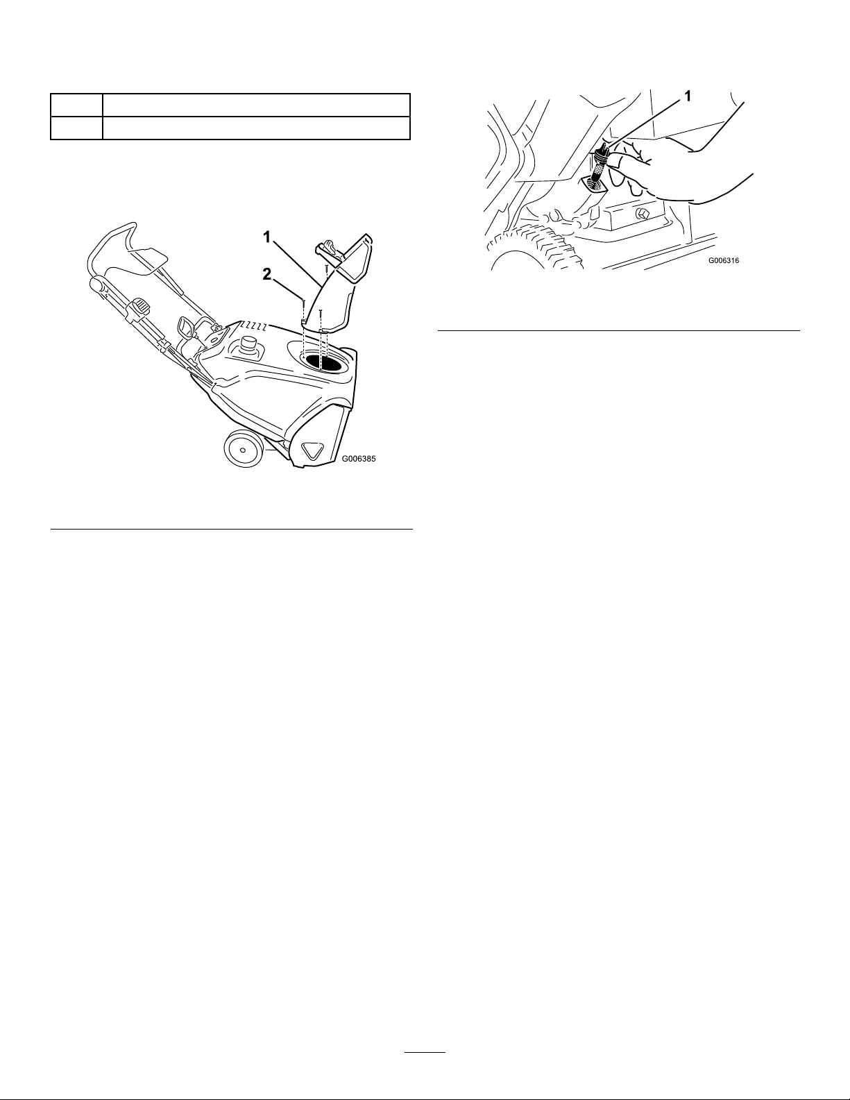
Installthedischargechuteasshown(Figure6).
Figure6
1.Dischargechute
2.Screw(3)
1.Movethesnowthrowertoalevelsurface.
2.Cleanaroundtheoilllcap(Figure7).
Figure7
1.Oilllcap
3.Unscrewtheoilllcapandremoveit.
4.Withthesnowthrowerintheoperatingposition,
carefullypouroilintothecrankcaseuntilthepoint
ofoverow.
5.Screwtheoilllcapintotheoilllholeandtighten
itsecurely.
4.AdjustingtheControlCable
Note:Foreasierinstallation,useasmallratchetwrench
totightenthescrews.
Important:Donotovertightenthescrews;
otherwiseyoumaydamagethedischargechuteand
preventitfromturningfreely.
3.FillingtheEnginewithOil
Procedure
Yoursnowthrowerdoesnotcomewithoilintheengine,
butitdoescomewithabottleofoil.
Important:Beforestartingtheengine,llthe
enginewithoil.
Note:Thebottleofoilmaycontainmorethanis
required.Donotoverlltheengine.
Maxll:21oz.(0.62l),type:automotivedetergentoil
withanAPIserviceclassicationofSJ,SL,orhigher.
•Fortemperaturesabove32°F(0°C),useSAE30.
•Fortemperaturesbetween0°Fand32°F(–18°Cand
0°C),useSAE5W30orSAE10.
Procedure
RefertoAdjustingtheControlCableinMaintenance.
•Fortemperaturesbelow0°F(–18°C),useSAE
0W30.
6
Page 7
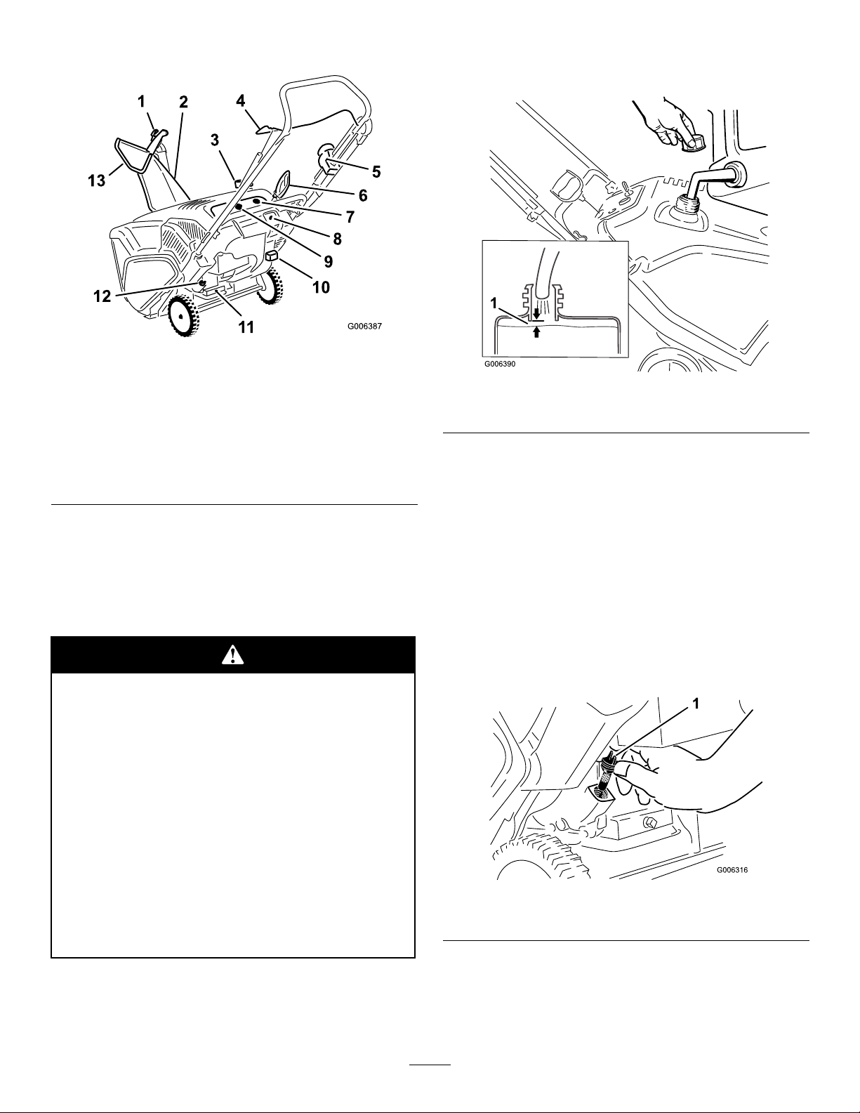
ProductOverview
Figure8
1.Chutedeectortrigger
2.Dischargechute9.Ignitionkey
3.Fueltankcap
4.Controlbar11.Oildrainplug
5.QuickShoot™control12.Oilllcap
6.Recoilstarthandle
7.Primer
8.Electric-startbutton
10.Chokelever
13.Chutedeector
(model38586only)
FillingtheFuelTank
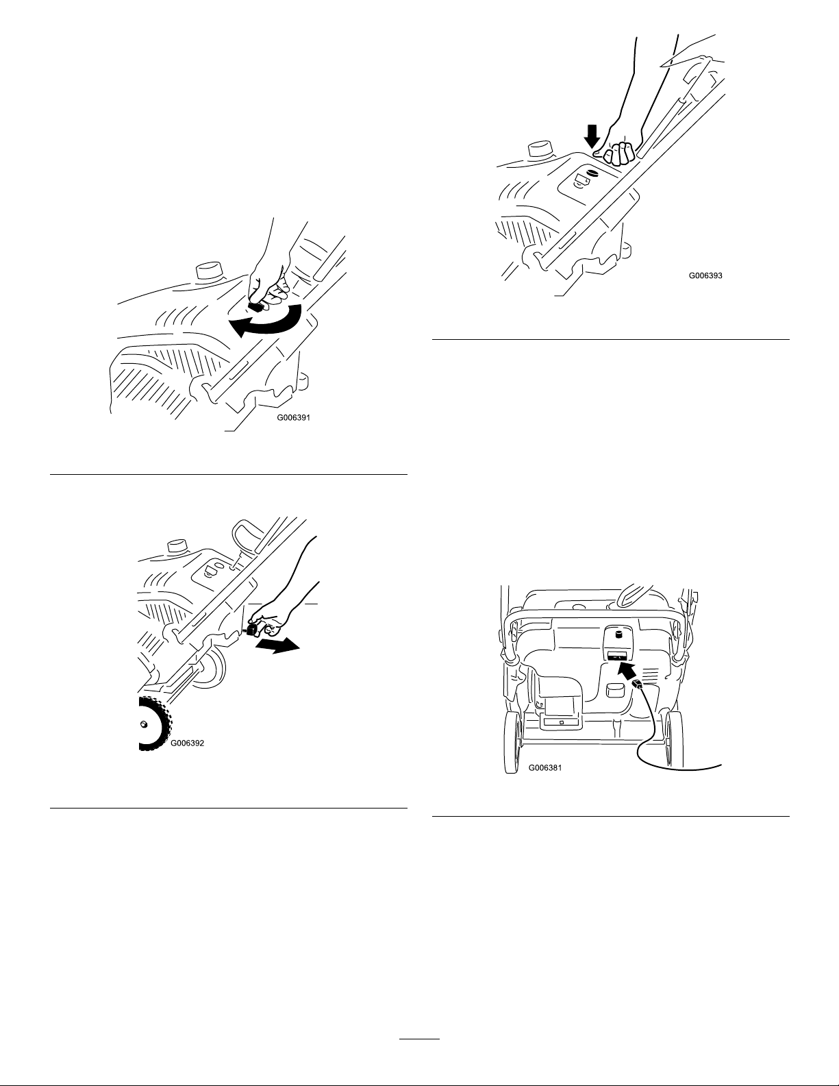
Fillthefueltankwithfreshunleadedgasoline(Figure9).
Figure9
1.1/4inch(6mm)
Important:DonotuseE85orE20fuel.Alternative
fuelswithhighalcoholcontentcancausehard
starting,poorengineperformance,andmaycause
internalenginedamage.
Operation
Note:Determinetheleftandrightsidesofthemachine
fromthenormaloperatingposition.
Gasolineisextremelyammableandexplosive.
Areorexplosionfromgasolinecanburnyou
andothers.
•Topreventastaticchargefromigniting
thegasoline,placethecontainerand/or
snowthroweronthegroundbeforelling,
notinavehicleoronanobject.
•Fillthetankoutdoorswhentheengineis
cold.Wipeupspills.
•Donothandlegasolinewhensmokingor
aroundanopenameorsparks.
•Storegasolineinanapprovedfuelcontainer,
outofthereachofchildren.
CheckingtheEngineOilLevel
ServiceInterval:Beforeeachuseordaily—Check
theengineoillevelandaddoilif
necessary.
1.Movethesnowthrowertoalevelsurface.
2.Cleanaroundtheoilllcap(Figure10).
Figure10
1.Oilllcap
3.Unscrewtheoilllcapandremoveit.
4.Iftheoillevelislow,keepthesnowthrowerinthe
operatingpositionandcarefullypouroilintothe
crankcaseuntilthepointofoverow .(Max.ll:21
7
Page 8
oz.(0.62l),type:SAE30detergentoilwithanAPI
serviceclassicationofSJ,SL,orhigher.)
5.Screwtheoilllcapintotheoilllholeandtighten
itsecurely.
StartingtheEngine
1.TurntheignitionkeyclockwisetotheOnposition
(Figure11).
Figure13
Note:Removeyourglovewhenyoupushinthe
primersothataircannotescapefromtheprimer
hole.
Figure11
2.Pulloutthechokelever(Figure12).
Figure12
1.Chokelever
Important:Donotusetheprimerorthechoke
iftheenginehasbeenrunningandishot.
Excessiveprimingmayoodtheengineand
preventitfromstarting.
4.Connectanextensioncordtoapowersourceand
thesnowthrower,andpushtheelectric-startbutton
(model38586only)(Figure14),orpulltherecoil
starthandle(Figure15).
Figure14
3.Firmlypushintheprimer3timeswithyourthumb,
holdingtheprimerinaforasecondbeforereleasing
iteachtime(Figure13).
8
Page 9
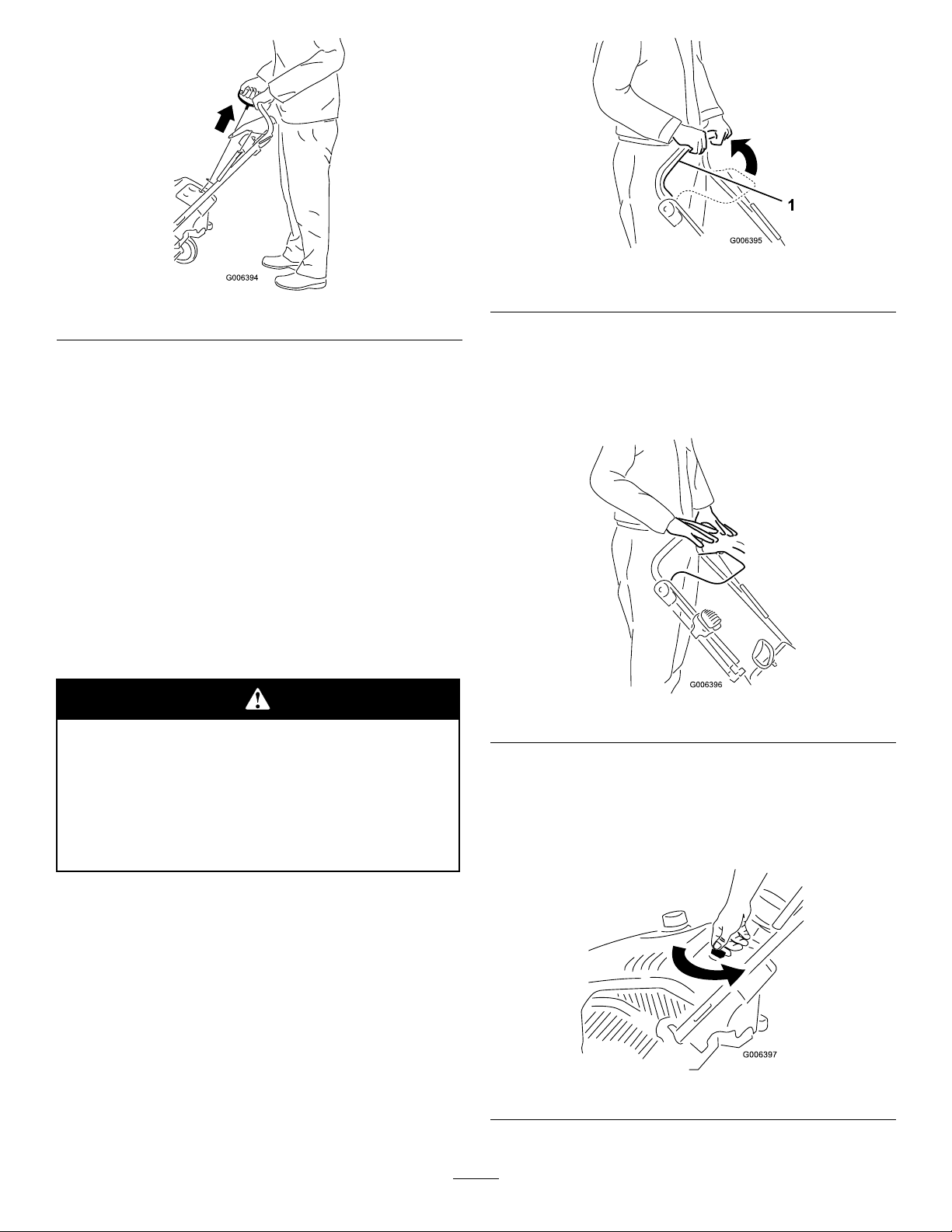
Figure15
Figure16
1.Controlbar
Important:Runtheelectricstarternomore
than10timesatintervalsof5secondson,then
5secondsoff.Runningtheelectricstarter
extensivelycanoverheatanddamageit.Ifthe
enginedoesnotstartafterthisseriesofattempts,
waitatleast40minutestoallowthestarterto
coolbeforeattemptingtostartitagain.Ifthe
enginedoesnotstartafterthesecondseriesof
attempts,takethesnowthrowertoanAuthorized
ServiceDealerforservice(model38586only).
5.Whiletheengineisrunning,pushinthechokelever
slowly.
6.Unplugtheextensioncordfromthepowersource
andthesnowthrower(model38586only).
Ifyouleavethesnowthrowerpluggedintoa
poweroutlet,someonecaninadvertentlystart
thesnowthrowerandinjurepeopleordamage
property(model38586only).
DisengagingtheRotorBlades
Todisengagetherotorblades,releasethecontrolbar
(Figure17).
Figure17
StoppingtheEngine
Unplugthepowercordwheneveryouarenot
startingthesnowthrower.
EngagingtheRotorBlades
Toengagetherotorblades,holdthecontrolbaragainst
thehandle(Figure16).
Tostoptheengine,turntheignitionkey
counterclockwisetotheOffposition(Figure18).
Figure18
9
Page 10
AdjustingtheDischargeChute
PreventingFreeze-upafter
andChuteDeector
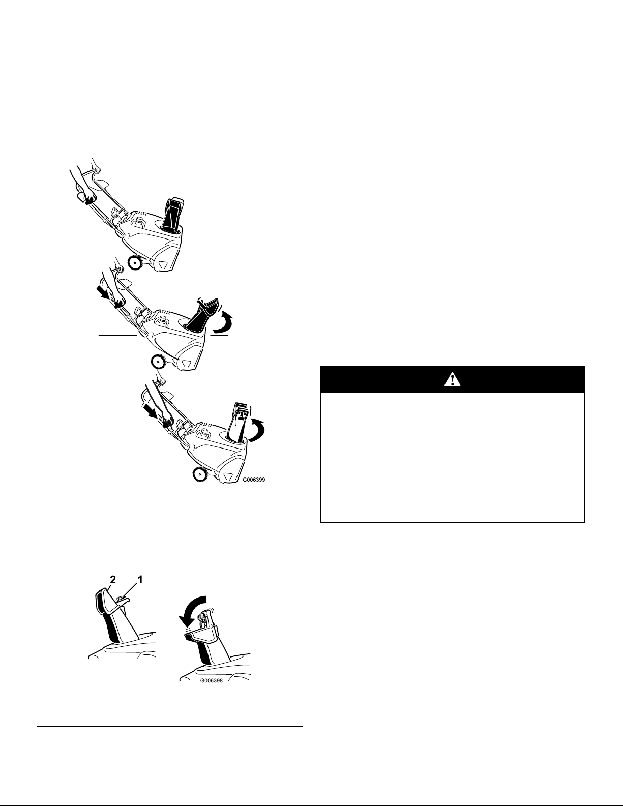
Toadjustthedischargechute,pressthetriggerofthe
QuickShoot™controlontherighthandsideofthe
handleandmoveitupordownalongthehandle.Moving
thecontroldownthehandlerotatesthedischargechute
totheleft;movingthecontrolupthehandlerotatesthe
dischargechutetotheright(Figure19).
Use
•Lettheenginerunforafewminutestoprevent
movingpartsfromfreezing.Stoptheengine,wait
forallmovingpartstostop,andremoveiceand
snowfromthesnowthrower.
•Cleanoffanysnowandicefromthebaseofthe
chute.
•Rotatethedischargechuteleftandrighttofreeit
fromanyicebuildup.
•WiththeignitionkeyintheOffposition,pullthe
recoilstarterhandleseveraltimesorpushtheelectric
startbuttononce(model38586only)topreventthe
recoilandelectricstartersfromfreezingup.
•Insnowyandcoldconditions,somecontrolsand
movingpartsmayfreeze.Donotuseexcessiveforce
whentryingtooperatefrozencontrols.Ifyouhave
difcultyoperatinganycontrolorpart,startthe
engineandletitrunforafewminutes.
OperatingTips
Figure19
Toraiseorlowertheangleofthechutedeector,press
thetriggeronthechutedeectorandmovethechute
deectorupordown(Figure20).
Figure20
1.Chutedeectortrigger2.Chutedeector
Therotorbladescanthrowstones,toys,and
otherforeignobjectsandcauseseriouspersonal
injurytotheoperatorortobystanders.
•Keeptheareatobeclearedfreeofallobjects
thattherotorbladescouldpickupand
throw.
•Keepallchildrenandpetsawayfromthe
areaofoperation.
•Removethesnowassoonaspossibleafteritfalls.
•Ifthesnowthrowerdoesnotpropelitselfforward
onslipperysurfacesorinheavysnow,pushforward
onthehandle,butallowthesnowthrowertowork
atitsownpace.
•Overlapeachswathtoensurecompletesnow
removal.
•Dischargethesnowdownwindwheneverpossible.
10
Page 11
Maintenance
Note:Determinetheleftandrightsidesofthemachinefromthenormaloperatingposition.
RecommendedMaintenanceSchedule(s)
MaintenanceService
Interval
Afterthersthour
Aftertherst2hours
Beforeeachuseordaily
Yearly
Yearlyorbeforestorage
MaintenanceProcedure
•Checkthecontrolcableandadjustitifnecessary.
•Checkforloosefastenersandtightenthemifnecessary.
•Changetheengineoil.
•Checktheengineoillevelandaddoilifnecessary .
•Checkthecontrolcableandadjustitifnecessary.
•InspecttherotorbladesandhaveanAuthorizedServiceDealerreplacetherotor
bladesandscraperifnecessary.
•Changetheengineoil.
•Servicethesparkplugandreplaceitifnecessary.
•Checkforloosefastenersandtightenthemifnecessary.
•HaveanAuthorizedServiceDealerinspectthedrivebeltandreplaceitifnecessary.
•Preparethesnowthrowerforstorage.
AdjustingtheControlCable
CheckingtheControlCable
ServiceInterval:Afterthersthour—Check
thecontrolcableandadjustitif
necessary.
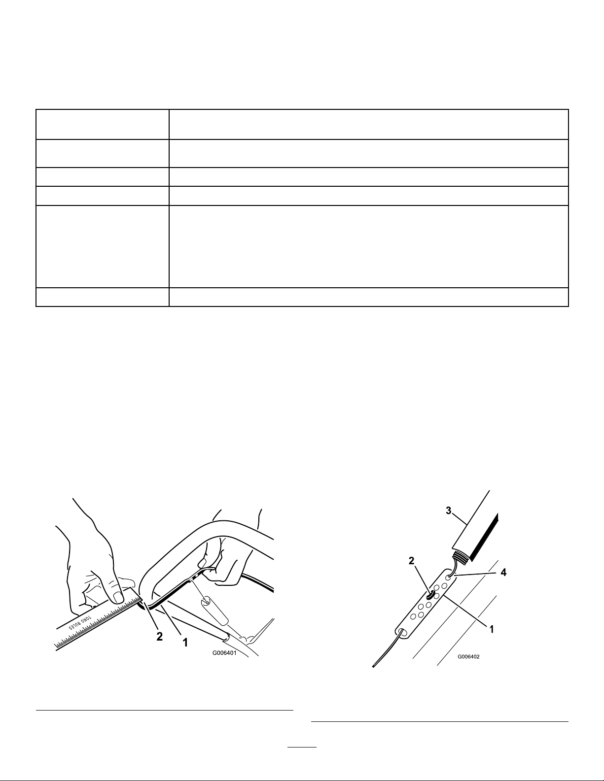
Note:Ensurethata1/16-inchto1/8-inch(2mmto3
mm)gapexistsbetweenthecontrolbarandthehandle
(Figure21).
Important:Thecontrolcablemustcontainsome
slackwhenyoudisengagethecontrolbarforthe
rotorbladestostopproperly.
Yearly—Checkthecontrolcableand
adjustitifnecessary.
Movethecontrolbarbacktowardthehandletoremove
theslackinthecontrolcable(Figure21).
Figure21
1.Controlbar2.1/16-inchto1/8-inch(2
mmto3mm)gap
AdjustingtheControlCable
1.Slideupthespringcoverandunhookthespring
fromtheadjusterlink(Figure22).
Figure22
1.Adjusterlink
2.Z-tting
3.Springcover
4.Unhookthespringhere.
11
Page 12
Note:Youcanpulluptheadjusterlinkandcableto
makeunhookingthespringeasier.
2.MovetheZ-ttingtoahigherorlowerholeonthe
adjusterlinkasneededtoobtainthe1/16-inchto
1/8-inch(2mmto3mm)gapbetweenthecontrol
barandthehandle(Figure21).
Note:MovingtheZ-ttinghigherdecreasesthe
gapbetweenthecontrolbarandthehandle;moving
itlowerincreasesthegap.
3.Hookthespringtotheadjusterlinkandslidethe
springcoverovertheadjusterlink.
4.Checktheadjustment;refertoCheckingtheControl
Cable.
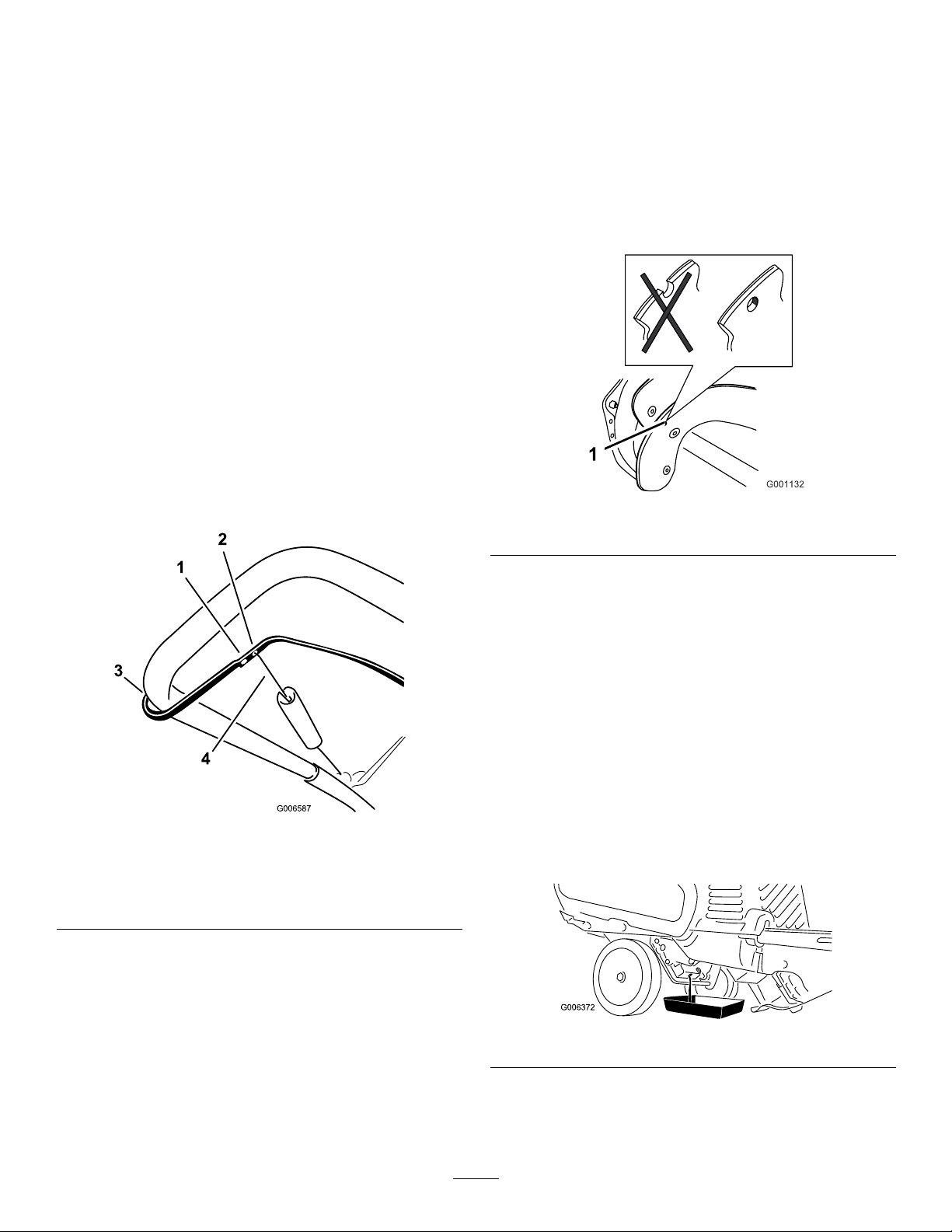
Note:Afterextendeduse,thedrivebeltmaywear
andloseitsproperbelttension.Ifthedrivebelt
slips(continuouslysqueals)underaheavyload,
disconnectthespringfromtheadjustorlinkand
movetheupperendofthespringtotheholethat
isfurtherfromthepivotpointinthecontrolbar
(Figure23).Thenconnectthespringtotheadjustor
linkandadjustthecontrolcable.
InspectingtheRotorBlades
ServiceInterval:Yearly—Inspecttherotorbladesand
haveanAuthorizedServiceDealer
replacetherotorbladesandscraperif
necessary.
Beforeeachsession,inspecttherotorbladesforwear.
Whenarotorbladeedgehasworndowntothewear
indicatorhole,haveanAuthorizedServiceDealer
replacetherotorbladesandthescraper(Figure24).
Figure24
1.Wearindicatorhole
Figure23
1.Removetheupperendof
springfromthishole
2.Inserttheupperendof
springintothishole
3.Pivotpoint
4.Upperendofspring
Note:Thebeltmayslip(squeal)inwetconditions;
todryoutthedrivesystem,starttherotorandrun
itwithoutaloadfor30seconds.
ChangingtheEngineOil
ServiceInterval:Aftertherst2hours
Yearly
Runtheengineafewminutesbeforechangingtheoil
towarmit.Warmoilowsbetterandcarriesmore
contaminants.
1.Stoptheengineandwaitforallmovingpartstostop.
2.Movethesnowthrowertoalevelsurface.
3.Placeanoildrainpanundertheoildrainplug,
removetheoildrainplug,andtipthesnowthrower
backwardanddraintheusedoilintheoildrainpan
Figure25).
Figure25
4.Afterdrainingtheusedoil,returnthesnowthrower
totheoperatingposition.
5.Installtheoildrainplugandtightenitsecurely.
12
Page 13
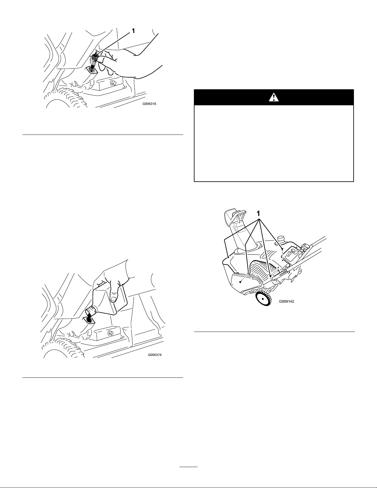
6.Cleanaroundtheoilllcap(Figure26).
ServicingtheSparkPlug
ServiceInterval:Yearly—Servicethesparkplugand
replaceitifnecessary.
UseaChampionRJ19LMsparkplugorequivalent.
1.Stoptheengineandwaitforallmovingpartstostop.
2.Waituntiltheenginehasfullycooled.
Figure26
1.Oilllcap
7.Unscrewtheoilllcapandremoveit(Figure26).
8.Withthesnowthrowerintheoperatingposition,
carefullypouroilintotheoilllholetothepoint
ofoverow(Figure27).
Maxll:21oz.(0.62l),type:automotivedetergent
oilwithanAPIserviceclassicationofSJ,SL,or
higher.
•Fortemperaturesabove32°F(0°C),useSAE30.
•Fortemperaturesbetween0°Fand32°F(–18°C
and0°C),useSAE5W30orSAE10.
•Fortemperaturesbelow0°F(–18°C),useSAE
0W30.
Aftertheenginehasbeenrunning,themufer
andotherenginecomponentswillbeveryhot
andwillseverelyburnyouifyoutouchthem.
Thisprocedurerequiresyoutoremovethe
exhaustbafefromoverthemuferandto
placeyourhandclosetothemuferandengine.
Allowtheenginetofullycoolbeforestarting
thisprocedure.
3.Removeandsavethefastenersthatsecurethe
shroudasshown(Figure28).
Figure27
9.Screwtheoilllcapintotheoilllhole,andtighten
itsecurely.
10.Wipeupanyspilledoil.
11.Disposeoftheusedoilproperlyatalocalrecycling
center.
Figure28
1.Removethese4fasteners
4.Liftupontheleftrearcorneroftheshroudand
pulltheexhaustbafedownandoutoftheengine
compartment(Figure29).
13
Page 14
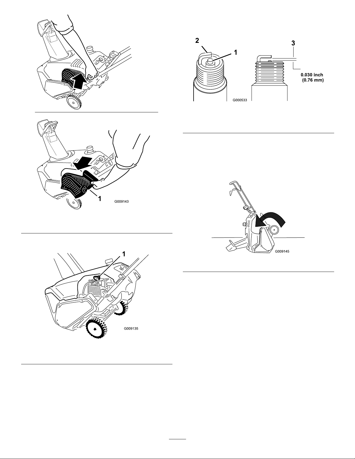
8.Setthegapontheplugto0.030inch(0.76mm)
(Figure31).
Figure31
1.Centerelectrodeinsulator3.Airgap(nottoscale)
2.Sideelectrode
9.Installthesparkplugandtightentheplugsecurely .
10.Connectthewiretothesparkplug.
11.Tipthesnowthrowerforwardontoitsfronttomake
installingtheexhaustbafeeasier(Figure32).
Figure29
1.Exhaustbafe
5.Disconnectthewirefromthesparkplug(Figure30).
Figure30
1.Spark-plugwire
6.Cleanaroundthesparkplug.
Figure32
12.Fromtherearleftposition,inserttheexhaustbafe
upintotheshroud.
Note:Ensurethattheupperlipoftheexhaust
bafetsintothetabsontheinsideoftheshroud
(Figure33).
7.Removethesparkplugfromthecylinderhead.
Important:Replaceacracked,fouled,or
dirtysparkplug.Donotcleantheelectrodes
becausegritenteringthecylindercandamage
theengine.
14
Page 15
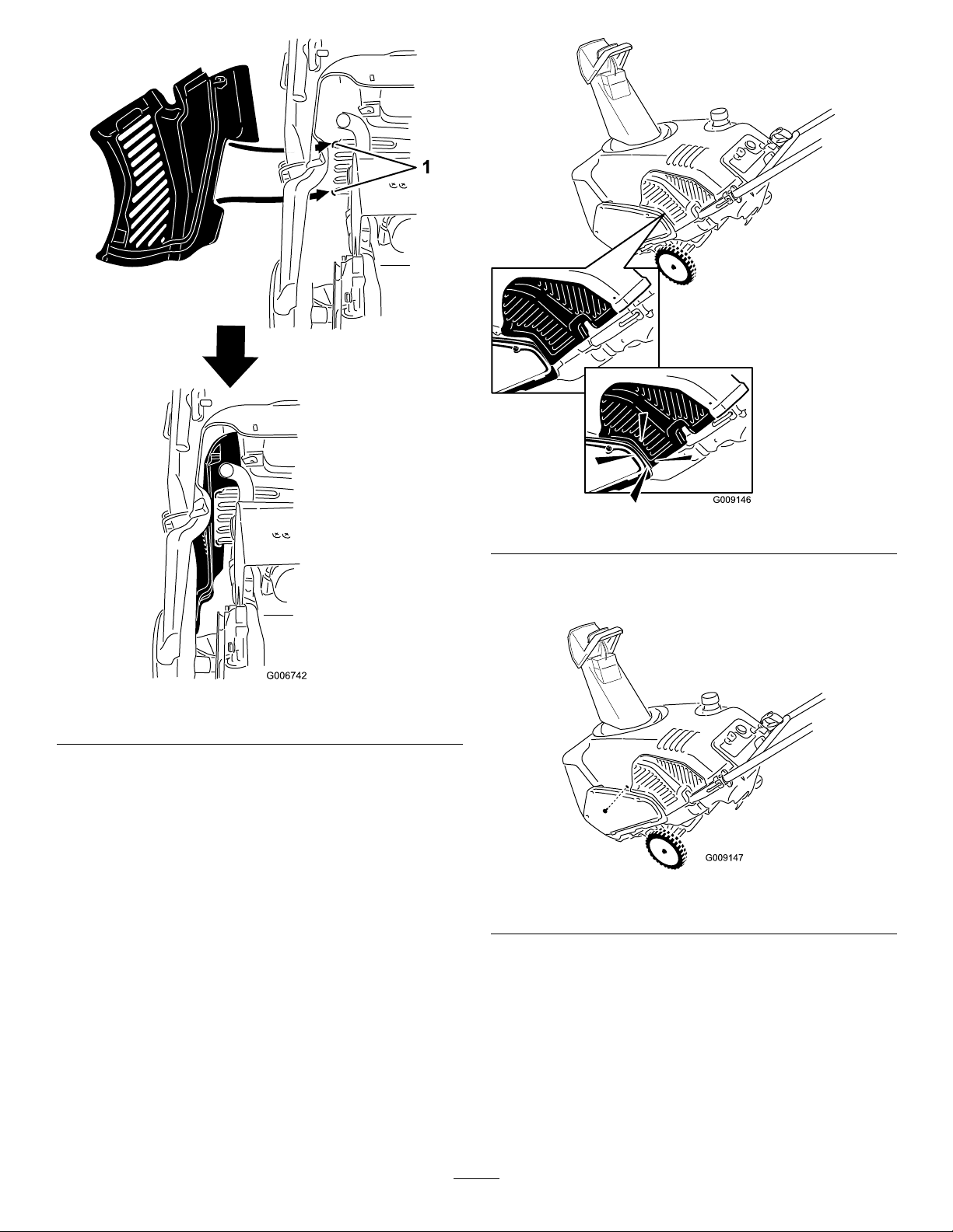
Figure33
1.Tabs
13.Installthe2screwsintotheexhaustbafe.
14.Returnthesnowthrowertotheoperatingposition.
15.Tuckthelowerlipoftheguardbehindthebeltcover
(Figure34).
Figure34
16.Securetheexhaustbafeusingthesmallsidescrew
thatyoupreviouslyremoved(Figure35).
Figure35
1.Smallsidescrewhere
15
Page 16
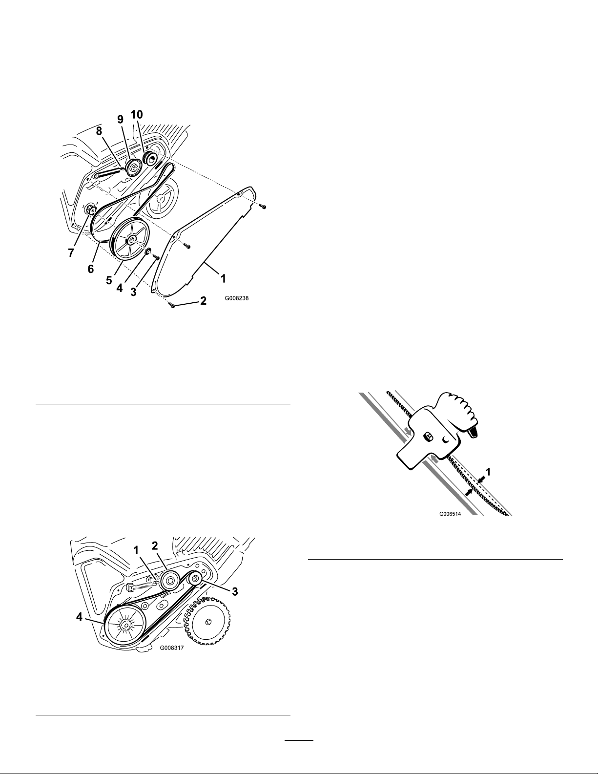
ReplacingtheDriveBelt
Ifdrivebeltbecomesworn,oil-soaked,excessively
cracked,frayed,orotherwisedamaged,replacethebelt.
1.Removethedrivebeltcoverbyremovingthe3bolts
asshowninFigureFigure36.
Note:Routethenewdrivebeltrstaroundthe
enginepulley,thentheidlerpulley ,andnallyaround
thelooserotorpulleypositionedjustabovetherotor
shaft(Figure36).
6.Installtherotorpulleyontotherotorshaft
(Figure36).
7.Installthecurvedwasherandtherotorpulleybolt
andtightenthemsecurely(Figure36).
Note:Theconcavesideofthecurvedwashergoes
againsttheoutsideofthepulley.
8.Installthebrakespringontotheidlerarm(Figure37).
9.Installthedrivebeltcoverwiththeboltsyou
removedinstep1.
Note:Ensurethatthedrivebeltisproperlyadjusted
andoperating;refertoCheckingtheControlCable
andAdjustingtheControlCable.
AdjustingtheQuickShoot™
Figure36
1.Drivebeltcover6.Drivebelt
2.Bolt(3)7.Rotorshaft
3.Rotorpulleybolt
4.Curvedwasher
5.Rotorpulley10.Enginepulley
8.Brakespring(unhookfrom
idlerarmhere)
9.Idlerpulley
2.Unhookthebrakespringfromtheidlerarmto
releasethebelttension(Figure36).
3.Removethescrewandcurvedwasherthatholdsthe
rotorpulley(Figure36).
4.Removetherotorpulleyandthedrivebelt
(Figure36).
5.Installthenewdrivebelt,routingitasshownin
(Figure37).
Control
Ifthereismorethan1/2inch(13mm)ofslackinthe
QuickShootcable(Figure38)orthedischargechute
doesnotrotateleftandrightinequalangles,adjustthe
QuickShootcontrolcables.
Figure38
1.1/2inch(13mm)maximumslack
1.LoosenthetwoQuickShootcontrolcableclamps
(Figure39).
Figure37
1.Brakespring(installon
idlerarmhere)
2.Idlerpulley4.Rotorpulley
3.Enginepulley
16
Page 17
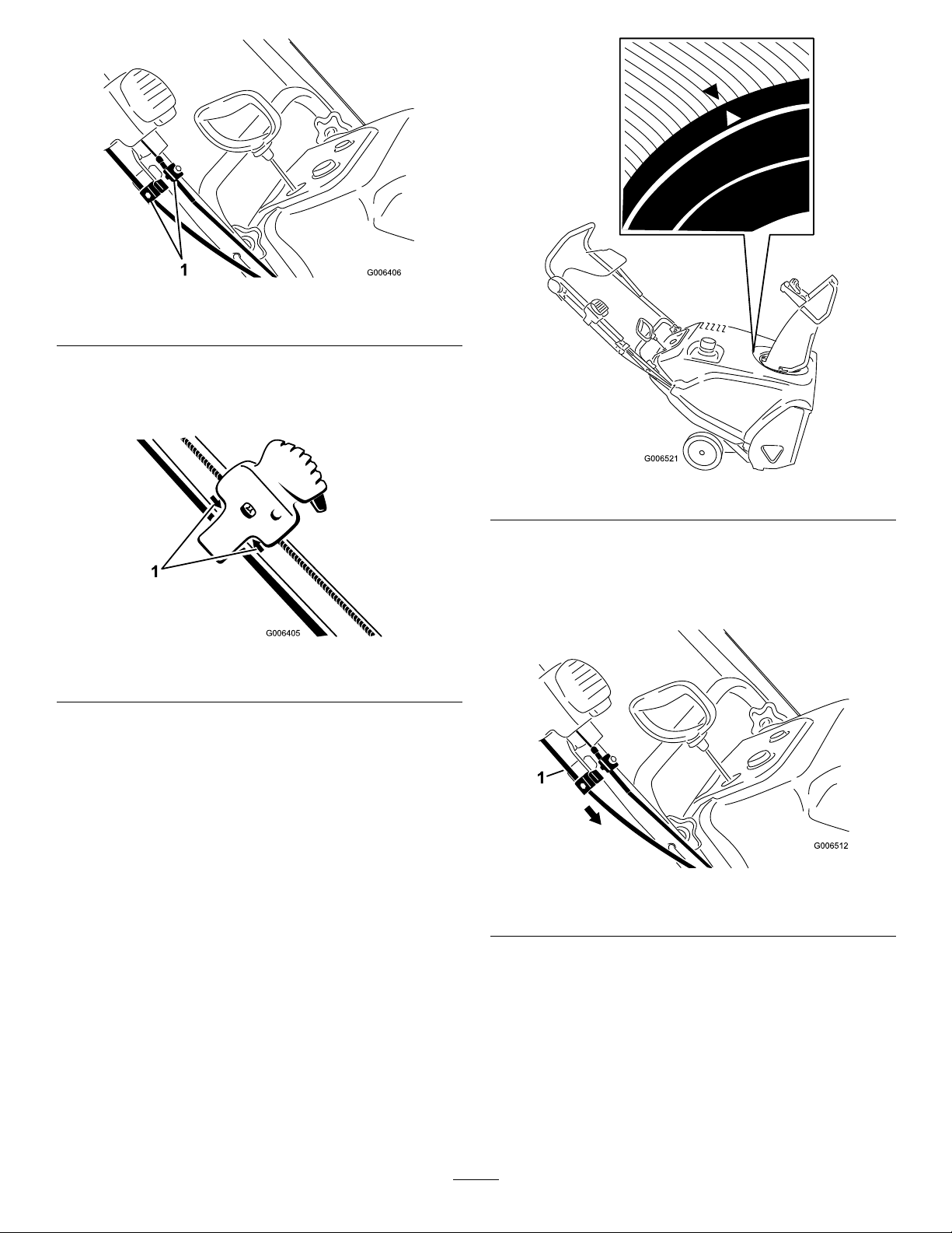
Figure39
1.Cableclamps
2.PositiontheQuickShootcontrolbetweenthetwo
arrowslocatedontherighthandsideoftheupper
handle(Figure40).
Figure40
1.Arrows
3.Rotatethedischargechutesothatitfacesstraight
aheadandthearrowonthebackofthedischarge
chutealignswiththearrowontheshroud(Figure41).
Figure41
4.Holdthedischargechuteinthestraight-ahead
position,pullthelowercablecasingdownwarduntil
youremovetheslackinthecable,andtightenthe
screwonthelowercableclampsecurely(Figure42).
Figure42
1.Lowercablecasing
5.Pulltheuppercablecasingforwarduntilyouremove
theslackinthecable,andtightenthescrewonthe
uppercableclampsecurely(Figure43).
17
Page 18
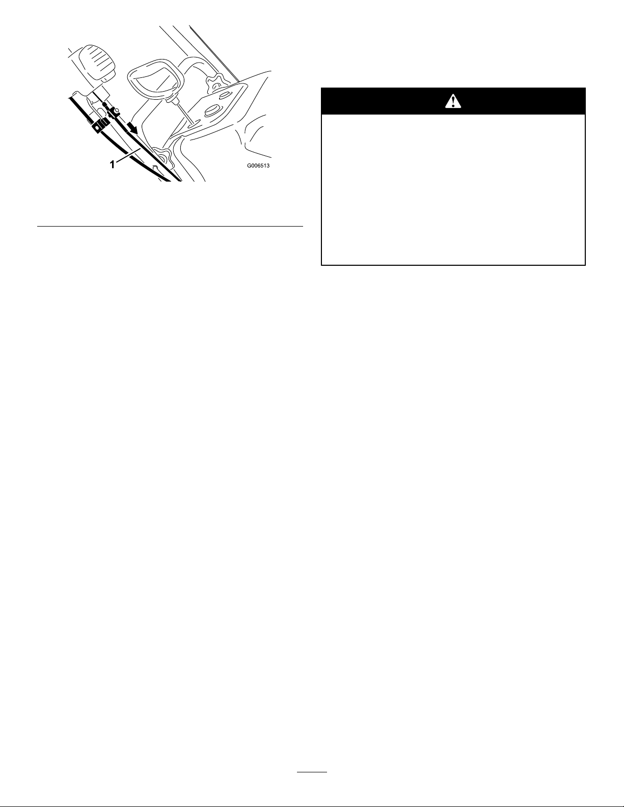
Figure43
1.Uppercablecasing
Note:Donotover-tensionthecables.Ifthecables
areover-tensioned,theQuickShootwillbehardto
operate.
Storage
StoringtheSnowthrower
•Gasolinefumesarehighlyammable,
explosive,anddangerousifinhaled.Ifyou
storetheproductinanareawithanopen
ame,thegasolinefumesmayigniteand
causeanexplosion.
•Donotstorethesnowthrowerinahouse
(livingarea),basement,oranyotherarea
whereignitionsourcesmaybepresent,
suchashotwaterandspaceheaters,clothes
dryers,furnaces,andotherlikeappliances.
1.Onthelastrefuelingoftheyear,addfuelstabilizer
tofreshfuelasdirectedbytheenginemanufacturer.
2.Runtheenginefor10minutestodistributethe
conditionedfuelthroughthefuelsystem.
3.Stoptheengine,allowittocool,andsiphonthefuel
tankorruntheengineuntilitstops.
4.Starttheengineandrunituntilitstops.
5.Chokeorprimetheengine,startitathirdtime,and
runtheengineuntilitwillnotstart.
6.Disposeofunusedfuelproperly .Recycleitaccording
tolocalcodes,oruseitinyourautomobile.
Note:Donotstorestabilizedgasolineformore
than90days.
7.Whiletheengineisstillwarm,changetheengineoil.
RefertoChangingtheEngineOil.
8.Removethesparkplug.
9.Squirt2teaspoonsofoilintothesparkplughole.
10.Installthesparkplugbyhandandthentightenit
securely.Ifyoudonothaveatorquewrench,tighten
theplugrmly.
11.WiththeignitionkeyintheOffposition,pullthe
recoilstarterslowlytodistributetheoilontheinside
ofthecylinder.
12.Cleanthesnowthrower.
13.Touchupchippedsurfaceswithpaintavailable
fromanAuthorizedServiceDealer.Sandaffected
areasbeforepainting,andusearustpreventativeto
preventthemetalpartsfromrusting.
18
Page 19

14.Tightenanyloosefasteners.Repairorreplaceany
damagedparts.
15.Coverthesnowthrowerandstoreitinaclean,dry
placeoutofthereachofchildren.Allowtheengine
tocoolbeforestoringitinanyenclosure.
19
Page 20

CCR 2450
Power Clear
Snow Commander
The Toro 5-Year GTS Starting Guarantee and
The Toro 2-Year Total Coverage Guarantee
A Full Warranty (Limited Warranty for Commercial Use)
Conditions and Products Covered under
The Toro Starting Guarantee
The Toro Company and its affi liate, Toro Warranty Company, guarantee
that your Toro GTS (Guaranteed to Start) engine, when used for residential
purposes*, will start on the fi rst or second pull for fi ve (5) years from the
date of purchase, if you provide the routine maintenance it requires, or we
will fi x it free of charge.
This warranty covers the cost of parts and labor, but you must pay transportation costs.
Guaranteed to Start Warranty Period
CCR 2450 5-years
Power Clear 5-years
Snow Commander 5-years
Conditions and Products Covered under
The Toro Total Coverage Guarantee
The Toro Company and its affi liate, Toro Warranty Company, promise
to repair any Toro Product used for residential purposes* if defective in
materials or workmanship or if it stops functioning due to the failure of a
component for a period of two (2) years from the date of purchase.
This warranty covers the cost of parts and labor, but you must pay transportation costs.
The following time periods apply from the date of purchase:
Snow Product Warranty Period
CCR 2450 2-year Full warranty
Power Clear 2-year Full warranty
Snow Commander 2-year Full warranty
Limited Warranty for Commercial Use
Gas-powered Toro Snowthrowers used for commercial, institutional, or
rental use are warranted for 45 days against defects in materials or workmanship.
Instructions for Obtaining Warranty Service
If you think that your Toro Product contains a defect in materials or
workmanship, or if a normal, able-bodied adult can no longer start your
product’s engine in one or two pulls, follow this procedure:
1. Contact any Toro Authorized or Master Service Dealer to arrange service
at their dealership. To locate a dealer convenient to you, refer to the
Yellow Pages of your telephone directory (look under Lawn Mowers)
or access our web site at www.Toro.com. You may also call our Toro
Customer Care Department toll free at 866-336-5205 (U.S. customers)
or 866-854-9033 (Canadian customers).
2. Bring the product and your proof of purchase (sales receipt) to the
Service Dealer.
If for any reason you are dissatisfi ed with the Service Dealer’s analysis or
with the assistance provided, contact us at:
Customer Care Department, Consumer Division
Toro Warranty Company
8111 Lyndale Avenue South
Bloomington, MN 55420-1196
866-336-5205 (U.S. customers)
866-854-9033 (Canadian customers)
You must maintain your Toro Product by following the maintenance procedures described in the Operator’s Manual. Such routine maintenance,
whether performed by a dealer or by you, is at your expense.
There is no other express warranty. This express warranty does not cover
the following:
Cost of regular maintenance service or parts, such as fi lters, fuel, lubri-
•
cants, oil changes, spark plugs, cable/linkage adjustments, or brake and
clutch adjustments
Any product or part which has been altered or misused or required
•
replacement or repair due to accidents or lack of proper maintenance
Repairs necessary due to electrical supply irregularities
•
Pickup and delivery charges
•
Operational misuse, neglect, or accidents
•
Repairs or attempted repairs by anyone other than a Toro Service outlet
•
Repairs or adjustments to correct starting diffi culties due to the following:
•
failure to follow proper maintenance procedures
-
snowthrower auger/paddles striking an object
-
contaminants in the fuel system
-
improper fuel or fuel/oil mixture (consult your Operator’s Manual if in
-
doubt)
failure to drain the fuel system prior to any period of non-use over
-
three months
Special operational conditions where start-
•
ing may require more than two pulls:
fi rst time starts after extended period of non-use over three months
-
or seasonal storage
improper starting procedures
-
If you are having diffi culty starting your unit, please check the Operator’s
Manual to ensure that you are using the correct starting procedures. This
can save an unnecessary visit to a Service Dealer.
All repairs covered by these warranties must be performed by an Authorized or Master Toro Service Dealer using Toro approved replacement
parts. Repair by a Toro Service Dealer is your sole remedy under these
warranties. Neither The Toro Company nor Toro Warranty Company is
liable for indirect, incidental, or consequential damages in connection with the use of the Toro Products covered by these warranties,
including any cost or expense of providing substitute equipment or
service during reasonable periods of malfunction or non-use pending
completion of repairs under these warranties. Some states do not allow exclusions of incidental or consequential damages, or limitations
on how long an implied warranty lasts, so the above exclusions and
limitations may not apply to you. This warranty gives you specific legal
rights, and you may also have other rights which vary from state to state.
Owner Responsibilities
Items and Conditions Not Covered
General Conditions
Customers who have purchased Toro products exported from the United States or Canada should contact their Toro Distributor (Dealer) to obtain guarantee policies for your country, province, or state. If for any reason you are dissatisfi ed with your Distributor’s service or have diffi culty obtaining guarantee
information, contact the Toro importer. If all other remedies fail, you may contact us at Toro Warranty Company.
*Residential purposes means use of the product on the same lot as your home. Use at more than one location is considered commercial use, and the
commercial use warranty would apply.
Countries Other than the United States or Canada
Part Number 374-0059 Rev. B
 Loading...