


CCR™QuickClear™Snowthrower
38563and38568
SchneefräseCCR™QuickClear™
38563and38568
CCR™QuickClear™-snøfreser
38563and38568
CCR™QuickClear™-snöslunga
38563and38568
FormNo.3440-104RevA
CV
www.T oro.com.
*3440-104*A


CCR
ModelNo.38563—SerialNo.405012000andUp
ModelNo.38568—SerialNo.405012000andUp
™
QuickClear
™
Snowthrower
FormNo.3432-401RevA
Operator'sManual
Introduction
Thismachineisintendedtobeusedbyresidential
homeowners.Itisdesignedprimarilyforremoving
snowfrompavedsurfaces,suchasdrivewaysand
sidewalks,andothersurfacesfortrafconresidential
orcommercialproperties.Itisnotdesignedfor
removingmaterialsotherthansnow,norisitdesigned
forclearinggravelsurfaces.Usingthisproductfor
purposesotherthanitsintendedusecouldprove
dangeroustoyouandbystanders.
Readthisinformationcarefullytolearnhowtooperate
andmaintainyourproductproperlyandtoavoid
injuryandproductdamage.Y ouareresponsiblefor
operatingtheproductproperlyandsafely.
Visitwww.T oro.comforproductsafetyandoperation
trainingmaterials,accessoryinformation,helpnding
adealer,ortoregisteryourproduct.
Wheneveryouneedservice,genuineT oroparts,or
additionalinformation,contactanAuthorizedService
DealerorToroCustomerServiceandhavethemodel
andserialnumbersofyourmachineready.Figure1
identiesthelocationofthemodelandserialnumbers
onthemachine.Writethenumbersinthespace
provided.
Important:Withyourmobiledevice,youcan
scantheQRcodeontheserialnumberdecal(if
equipped)toregisteryourproductandtoaccess
warranty,parts,andotherproductinformation.
Figure1
1.Modelandserialnumberlocation
ModelNo.
SerialNo.
Thismanualidentiespotentialhazardsandhas
safetymessagesidentiedbythesafety-alertsymbol
(Figure2),whichsignalsahazardthatmaycause
seriousinjuryordeathifyoudonotfollowthe
recommendedprecautions.
g000502
Figure2
Safety-alertsymbol
Thismanualuses2wordstohighlightinformation.
Importantcallsattentiontospecialmechanical
informationandNoteemphasizesgeneralinformation
worthyofspecialattention.
ThisproductcomplieswithallrelevantEuropean
directives;fordetails,pleaseseetheseparateproduct
specicDeclarationofConformity(DOC)sheet.
Important:Ifyouareusingthismachineabove
1500m(5,000ft)foracontinuousperiod,ensure
thattheHighAltitudeKithasbeeninstalled
sothattheenginemeetsCARB/EPAemission
regulations.TheHighAltitudeKitincreases
engineperformancewhilepreventingspark-plug
fouling,hardstarting,andincreasedemissions.
Onceyouhaveinstalledthekit,attachthe
high-altitudelabelnexttotheserialdecalonthe
machine.ContactanyAuthorizedToroService
DealertoobtaintheproperHighAltitudeKitand
high-altitudelabelforyourmachine.Tolocate
adealerconvenienttoyou,accessourwebsite
atwww.Toro.comorcontactourToroCustomer
CareDepartmentatthenumber(s)listedinyour
EmissionControlWarrantyStatement.Remove
thekitfromtheengineandrestoretheengineto
g291846
itsoriginalfactorycongurationwhenrunningthe
engineunder1500m(5,000ft).Donotoperatean
enginethathasbeenconvertedforhigh-altitude
useatloweraltitudes;otherwise,youcould
overheatanddamagetheengine.
©2019—TheToro®Company
8111LyndaleAvenueSouth
Bloomington,MN55420
CV
Registeratwww.Toro.com.
OriginalInstructions(EN)
PrintedinMexico
AllRightsReserved
*3432-401*A

Ifyouareunsurewhetherornotyourmachinehas
beenconvertedforhigh-altitudeuse,lookforthe
followinglabel(Figure3).
Figure3
Contents
Introduction...............................................................1
Safety.......................................................................3
GeneralSafety...................................................3
SafetyandInstructionalDecals..........................4
Setup........................................................................5
1UnfoldingtheHandle.......................................5
2InstallingtheDischargeChute.........................5
decal127-9363
3FillingtheEnginewithOil.................................5
4AdjustingtheControlCable..............................6
ProductOverview.....................................................7
Specications....................................................7
Attachments/Accessories...................................7
Operation..................................................................7
BeforeOperation...................................................7
BeforeOperationSafety.....................................7
FillingtheFuelT ank............................................8
CheckingtheEngine-OilLevel............................8
DuringOperation...................................................8
DuringOperationSafety.....................................8
StartingtheEngine.............................................9
EngagingtheRotorBlades...............................10
DisengagingtheRotorBlades..........................10
ShuttingOfftheEngine......................................11
AdjustingtheDischargeChuteandChute
Deector........................................................11
ClearingaCloggedDischargeChute.................11
OperatingTips.................................................12
AfterOperation....................................................12
AfterOperationSafety......................................12
PreventingFreeze-upafterUse........................12
Maintenance...........................................................13
RecommendedMaintenanceSchedule(s)...........13
MaintenanceSafety..........................................13
CheckingandAdjustingtheControl
Cable............................................................13
InspectingtheRotorBlades..............................14
ChangingtheEngineOil...................................15
ServicingtheSparkPlug...................................16
ReplacingtheDriveBelt...................................17
AdjustingtheQuickShootControl....................18
Storage...................................................................20
StorageSafety..................................................20
StoringtheMachine..........................................20
2

Safety
Thismachinehasbeendesignedinaccordancewith
ENISO8437specications.
GeneralSafety
Thisproductiscapableofamputatinghandsand
feetandofthrowingobjects.Alwaysfollowallsafety
instructionstoavoidseriouspersonalinjury.
•Readandunderstandthecontentsofthis
Operator’sManualbeforeyoustarttheengine.
Ensurethateveryoneusingthisproductknows
howtouseit,knowshowtoshutofftheengine
quickly,andunderstandsthewarnings.
•Shutofftheenginewheneveryouleavethe
operatingpositionforanyreason.
•Donotputyourhandsorfeetnearmovingparts
onthemachine.
•Donotoperatethemachinewithoutallguards
andothersafetyprotectivedevicesinplaceand
working.
•Keepclearofanydischargeopening.Keep
bystanders,especiallysmallchildren,outofthe
operatingarea.
•Neverallowchildrentooperatethemachine.
3

SafetyandInstructional
Decals
Safetydecalsandinstructionsare
easilyvisibletotheoperatorandare
locatednearanyareaofpotential
danger.Replaceanydecalthatis
damagedormissing.
94-2577
1.Toengagetherotorblades,holdthecontrolbaragainst
thehandle.
2.Todisengagetherotorblades,releasethecontrolbar.
OrderPartNo.117-9121
Model38563only;orderPartNo.117-6036
decal117-9102
decal94-2577
1.Warning—readthe
Operator'sManual.
2.Cutting/dismemberment
hazard,impeller—shutoff
theengineandwaitfor
theaugertostopbefore
leavingthemachine.
3.Thrownobject
hazard—keepbystanders
away.
4.Explosionhazard—donot
tipthemachine.
5.Engineswitch—on
117-9102
6.Engineswitch—off
7.Primer
8.Pushtheprimer3timesto
primetheengine.
9.ReadtheOperator's
Manualbeforechecking
theengine-oillevel.
115-5698
1.Cutting/dismembermenthazard,impellerandauger—do
notplaceyourhandinthechute;removethekeyandread
theOperator’sManualbeforeperformingmaintenance.
Model38568only;orderPartNo.117-6046
decal115-5698
decal117-9103
117-9103
1.Warning—readthe
Operator'sManual.
2.Cutting/dismemberment
hazard,impeller—shutoff
theengineandwaitfor
theaugertostopbefore
leavingthemachine.
3.Thrownobject
hazard—keepbystanders
away.
4.Explosionhazard—donot
tipthemachine.
5.Engineswitch—on10.Plugthemachineinto
6.Engineswitch—off
7.Primer
8.Pushtheprimer3timesto
primetheengine.
9.ReadtheOperator's
Manualbeforechecking
theengine-oillevel.
powertheelectricstarter.
4

Setup
1
UnfoldingtheHandle
NoPartsRequired
Procedure
g263299
2
InstallingtheDischargeChute
NoPartsRequired
Procedure
g262492
5

3
FillingtheEnginewithOil
NoPartsRequired
Procedure
4
AdjustingtheControlCable
NoPartsRequired
Procedure
RefertoAdjustingtheControlCable(page14).
g253610
6

ProductOverview
Figure7
1.Chute-deectortrigger
2.Dischargechute9.Key
3.Fuel-tankcap
4.Controlbar11.Oil-drainplug
5.QuickShoot™control12.Oilll/dipstick
6.Recoil-starthandle
7.Primer
8.Electric-startbutton
10.Chokelever
13.Chutedeector
(Electric-startmodels
only)
Operation
BeforeOperation
BeforeOperationSafety
GeneralSafety
•Forelectric-startmodelsonly:Useextension
cordsandreceptaclesasspeciedinthemanual.
Inspecttheelectricalcordbeforepluggingitinto
apowersource.Ifthecordisdamaged,replace
it.Unplugthepowercordwheneveryouarenot
startingthemachine.
•Wearappropriateclothing,includingeye
g011431
protection;longpants;substantial,slip-resistant
footwear;andhearingprotection.Tiebacklong
hair,securelooseclothing,anddonotwearloose
jewelry.
•Thoroughlyinspecttheareawhereyouwillusethe
machine,andremovealldoormats,sleds,boards,
wires,andotherforeignobjects.
•Ifashield,safetydevice,ordecalisdamaged,
illegible,ormissing,repairorreplaceitbefore
beginningoperation.Also,tightenanyloose
fasteners.
Specications
ModelWeightLengthWidthHeight
38563
38568
Attachments/Accessories
AselectionofT oroapprovedattachmentsand
accessoriesisavailableforusewiththemachine
toenhanceandexpanditscapabilities.Contact
yourAuthorizedServiceDealerorauthorizedT oro
distributororgotowww.Toro.comforalistofall
approvedattachmentsandaccessories.
Toensureoptimumperformanceandcontinuedsafety
certicationofthemachine,useonlygenuineT oro
replacementpartsandaccessories.Replacement
partsandaccessoriesmadebyothermanufacturers
couldbedangerous,andsuchusecouldvoidthe
productwarranty.
37kg
(82lb)122cm54cm107cm
39kg
(87lb)
(48
inches)
(21
inches)
FuelSafety
Fuelisextremelyammableandexplosive.Areor
explosionfromfuelcanburnyouandothers.
•Topreventastaticchargefromignitingthefuel,
placethecontainerand/ormachineontheground
(42
inches)
beforelling,notinavehicleoronanobject.
•Fillthefueltankoutdoorswhentheengineiscold.
Replacethefuelcapsecurelyandwipeupspills.
•Donothandlefuelwhensmokingoraroundan
openameorsparks.
•Storefuelinanapprovedfuelcontainer,outofthe
reachofchildren.
•Whenfuelisinthetank,tipthemachineonlyas
directedintheinstructions.
•Ifyouspillfuelonyourclothing,changeyour
clothingimmediately.
7

FillingtheFuelTank
•Forbestresults,useonlyclean,fresh(lessthan
30daysold),unleadedgasolinewithanoctane
ratingof87orhigher((R+M)/2ratingmethod).
•Oxygenatedfuelwithupto10%ethanolor15%
MTBEbyvolumeisacceptable.
•Donotuseethanolblendsofgasoline(such
asE15orE85)withmorethan10%ethanolby
volume.Performanceproblemsand/orengine
damagemayresultwhichmaynotbecovered
underwarranty.
•Donotusegasolinecontainingmethanol.
•Donotstorefueleitherinthefueltankorfuel
containersoverthewinterunlessyouuseafuel
stabilizer.
•Donotaddoiltogasoline.
CheckingtheEngine-OilLevel
ServiceInterval:Beforeeachuseordaily
Donotllabovethebottomofthefueltankneck
(Figure8).
g216203
Figure8
Important:Forbestresults,purchaseonlythe
quantityoffuelthatyouexpecttousein30days.
Otherwise,youmayusefuelstabilizer/conditioner
inthemachineatalltimestokeepthefuelfresh
longerwhenusedasdirectedbythefuel-stabilizer
manufacturer.
DuringOperation
DuringOperationSafety
GeneralSafety
•Shutofftheenginebeforeuncloggingthe
machineandalwaysuseastick.
•Staybehindthehandlesandawayfromthe
dischargeopeningwhileoperatingthemachine.
Keepyourface,hands,feet,andanyotherpart
g293231
Figure9
ofyourbodyorclothingawayfrommovingor
rotatingparts.
•Neverdirectthedischargetowardpeopleorareas
wherepropertydamagecanoccur.
•Useyourfullattentionwhileoperatingthe
machine.Donotengageinanyactivitythat
causesdistractions;otherwise,injuryorproperty
damagemayoccur.
•Exercisecautiontoavoidslippingorfalling,
especiallywhenoperatingthemachineinreverse.
•Alwaysbesureofyourfooting,andkeeparm
holdonthehandles.Walk;neverrun.
8

•Exerciseextremecautionwhenoperatingthe
machineonaslope.
•Donotoperatethemachinewithoutgoodvisibility
orlight.
•Lookbehindandusecarewhenbackingupthe
machine.
•Whennotactivelyclearingsnow,disengagepower
totheauger.
•Exerciseextremecautionwhenoperatingthe
machineonwalksorroads.Stayalertforhidden
hazardsortrafc.
•Neverattempttomakeanyadjustmentswhile
theengineisrunning,exceptasdirectedinthe
instructions.
•Afterstrikingaforeignobject,shutofftheengine,
removethekey ,andinspectthemachinefor
damage.Repairanydamagebeforestartingthe
machine.
•Ifthemachinestartstovibrateabnormally ,shutoff
theengineandcheckimmediatelyforthecause.
•Donotruntheengineindoors;exhaustfumesare
dangerous.
•Donotoverloadthemachinecapacityby
attemptingtoclearsnowattoofastarate.
•Shutofftheenginewheneveryouleavethe
operatingposition,beforeclearingorunclogging
thecollector,rotor,ordischargechute,andwhen
makinganyrepairs,adjustments,orinspections.
StartingtheEngine
Note:Removeyourglovewhenyoupushintheprimersothataircannotescapefromtheprimerhole.
Important:Donotusetheprimerorthechokeiftheenginehasbeenrunningandishot.Excessive
primingmayoodtheengineandpreventitfromstarting.
StandardModels
g257388
Figure10
9

Electric-StartModels
Figure11
Note:UseonlyaUL-listed,16-gaugeextensioncordthatisrecommendedforoutdooruseandisnotlonger
than15m(50ft).
WARNING
g257387
Theelectricalcordcanbecomedamaged,causingashockorre.
Thoroughlyinspecttheelectricalcordbeforepluggingitintoapowersource.Ifthecordis
damaged,donotuseittostartthemachine.Replaceorrepairthedamagedcordimmediately.
ContactanAuthorizedServiceDealerforassistance.
CAUTION
Ifyouleavethemachinepluggedintoapowersource,someonecaninadvertentlystartthe
machineandinjurepeopleordamageproperty(electric-startmodelsonly).
Unplugthepowercordwheneveryouarenotstartingthemachine.
EngagingtheRotorBlades
Toengagetherotorblades,holdthecontrolbar
againstthehandle(Figure12).
DisengagingtheRotor
Blades
Todisengagetherotorblades,releasethecontrolbar
(Figure13).
Figure12
g219303
g011230
Figure13
10

ShuttingOfftheEngine
Toshutofftheengine,turnthekeycounterclockwise
totheOFFposition(Figure14).
Figure14
AdjustingtheDischarge
ChuteandChuteDeector
Toadjustthedischargechute,pressthetriggerofthe
QuickShoot™controlontherightsideofthehandle
andmoveitupordownalongthehandle.Movingthe
controldownthehandlerotatesthedischargechute
totheleft;movingthecontrolupthehandlerotates
thedischargechutetotheright(Figure15).
g011433
g006399
Figure15
Toraiseorlowertheangleofthechutedeector,
pressthetriggeronthechutedeectorandmovethe
chutedeectorupordown(Figure16).
Figure16
1.Chute-deectortrigger2.Chutedeector
ClearingaClogged
DischargeChute
Toclearthechute:
•Shuttheengineoff!
•Wait10secondstoensurethattherotorblades
havestoppedrotating.
•Alwaysuseaclean-outtool;neveruseyourhands.
11
g006398

OperatingTips
•Cleanoffanysnowandicefromthebaseofthe
chute.
WARNING
Therotorbladescanthrowstones,toys,
andotherforeignobjectsandcauseserious
personalinjurytoyouorbystanders.
•Keeptheareatobeclearedfreeofall
objectsthattherotorbladescouldpickup
andthrow.
•Keepallchildrenandpetsawayfromthe
areaofoperation.
•Removethesnowassoonaspossibleafteritfalls.
•Overlapeachswathtoensurecompletesnow
removal.
•Dischargethesnowdownwindwheneverpossible.
•Ifthemachinedoesnotpropelitselfforwardon
slipperysurfacesorinheavysnow,pushforward
onthehandle,butallowthemachinetoworkat
itsownpace.
•Themachinemayleaverubbermarksonnew
brushedorlight-coloredconcrete.T estonan
inconspicuouslocationbeforeuse.Thesemarks
arenotpermanent.
•Rotatethedischargechuteleftandrighttofree
itfromanyicebuildup.
•Withthekeyremoved,pulltherecoil-starthandle
severaltimesorconnecttheelectricalcordto
apowersourceandthemachineandpushthe
electric-startbuttononcetopreventtherecoil
starterand/ortheelectricstarterfromfreezingup
(electric-startmodelsonly).
•Insnowyandcoldconditions,somecontrolsand
movingpartsmayfreeze.Donotuseexcessive
forcewhentryingtooperatefrozencontrols.Ifyou
havedifcultyoperatinganycontrolorpart,start
theengineandletitrunforafewminutes.
AfterOperation
AfterOperationSafety
GeneralSafety
•Neverstorethemachinewithfuelinthefuel
tankinsideabuildingwhereignitionsourcesare
present,suchashotwaterheaters,spaceheaters,
orclothesdryers.Allowtheenginetocoolbefore
storingthemachineinanyenclosure.
•Whenstoringthemachineformorethan30
days,refertoStorage(page20)forimportant
information.
•Runthemachineafewminutesafterthrowing
snowtopreventfreeze-upofthecollectorand
rotor.
PreventingFreeze-upafter
Use
•Lettheenginerunforafewminutestoprevent
movingpartsfromfreezing.Shutofftheengine,
waitforallmovingpartstostop,andremoveice
andsnowfromthemachine.
12

Maintenance
RecommendedMaintenanceSchedule(s)
MaintenanceService
Interval
Afterthersthour
Aftertherst2hours
Beforeeachuseordaily
Yearly
Yearlyorbeforestorage
MaintenanceProcedure
•Checkthecontrolcableandadjustitifnecessary.
•Checkforloosefastenersandtightenthemifnecessary .
•Changetheengineoil.
•Checktheengine-oillevelandaddoilifnecessary.
•Checkthecontrolcableandadjustitifnecessary.
•InspecttherotorbladesandhaveanAuthorizedServiceDealerreplacetherotor
bladesandscraperifnecessary .
•Changetheengineoil.
•Servicethesparkplugandreplaceitifnecessary.
•Checkforloosefastenersandtightenthemifnecessary .
•HaveanAuthorizedServiceDealerinspectthedrivebeltandreplaceitifnecessary .
•Preparethemachineforstorage.
MaintenanceSafety
Readthefollowingsafetyprecautionsbefore
performinganymaintenanceonthemachine:
•Shutofftheengine,removethekey,andwait
forallmovementtostopbeforeyouleavethe
operator’sposition.Allowthemachinetocool
beforeadjusting,servicing,cleaning,orstoringit.
•Alwaysweareyeprotectionwhileperformingan
adjustmentorrepairtoprotectyoureyesfrom
foreignobjectsthatthemachinemaythrow.
•Checkallfastenersatfrequentintervalsforproper
tightnesstoensurethatthemachineisinsafe
workingcondition.
•Donotchangethegovernorsettingsontheengine.
PurchaseonlygenuineT ororeplacementparts
andaccessories.
g011233
Figure17
1.Controlbar2.2mmto3mm(1/16inch
to1/8inch)gap
CheckingandAdjustingthe
ControlCable
CheckingtheControlCable
ServiceInterval:Afterthersthour—Checkthe
controlcableandadjustitif
necessary.
Yearly—Checkthecontrolcableandadjustit
ifnecessary.
Movethecontrolbarbacktowardthehandleto
removetheslackinthecontrolcable(Figure17).
Note:Ensurethata2mmto3mm(1/16inchto
1/8inch)gapexistsbetweenthecontrolbarandthe
handle(Figure17).
Important:Thecontrolcablemustcontainsome
slackwhenyoudisengagethecontrolbarforthe
rotorbladestostopproperly.
13

AdjustingtheControlCable
1.Slideupthespringcoverandunhookthespring
fromtheadjusterlink(Figure18).
Figure18
1.Adjusterlink
2.Z-tting
Note:Youcanpulluptheadjusterlinkand
cabletomakeunhookingthespringeasier.
3.Springcover
4.Unhookthespringhere.
g011232
Figure19
g006402
1.Upperendofspring
2.Inserttheupperendof
springintothishole
3.Pivotpoint
4.Removetheupperendof
springfromthishole
Note:Thebeltmayslip(squeal)inwet
conditions;todryoutthedrivesystem,startthe
rotorandrunitwithoutaloadfor30seconds.
2.MovetheZ-ttingtoahigherorlowerholeon
theadjusterlinkasneededtoobtainthe2mm
to3mm(1/16inchto1/8inch)gapbetweenthe
controlbarandthehandle(Figure18).
Note:MovingtheZ-ttinghigherdecreasesthe
gapbetweenthecontrolbarandthehandle;
movingitlowerincreasesthegap.
3.Hookthespringtotheadjusterlinkandslidethe
springcoverovertheadjusterlink.
4.Checktheadjustment;refertoCheckingthe
ControlCable(page13).
Note:Afterextendeduse,thedrivebeltmay
wearandloseitsproperbelttension.Ifthedrive
beltslips(continuouslysqueals)underaheavy
load,disconnectthespringfromtheadjustorlink
andmovetheupperendofthespringtothehole
thatisfurtherfromthepivotpointinthecontrol
bar(Figure19).Thenconnectthespringtothe
adjustorlinkandadjustthecontrolcable.
InspectingtheRotorBlades
ServiceInterval:Yearly—Inspecttherotorblades
andhaveanAuthorizedService
Dealerreplacetherotorbladesand
scraperifnecessary.
Beforeeachsession,inspecttherotorbladesfor
wear.Whenarotor-bladeedgehasworndownto
thewear-indicatorhole,haveanAuthorizedService
Dealerreplacetherotorbladesandthescraper
(Figure20).
1.Thewear-indicatorholeis
intact;youdonotneedto
replacetherotorblades.
14
g011544
Figure20
2.Thewear-indicatorholeis
exposed;replacetherotor
bladesandscraper.

ChangingtheEngineOil
ServiceInterval:Aftertherst2hours
Yearly
Ifpossible,runtheengineforafewminutesbefore
changingtheoiltowarmit.Warmoilowsbetterand
carriesmorecontaminants.
EngineOilSpecications
Engineoilcapacity
OilviscosityRefertoFigure23.
APIserviceclassicationSJorhigher
0.60L(20oz)*
*Thereisresidualoilinthecrankcaseafteryoudrain
theoil.Donotpourtheentirecapacityofoilintothe
crankcase.Fillthecrankcasewithoilasdirectedin
thefollowingsteps.
1.Siphonthefuelfromthefueltankintoan
approvedfuelcontainer,orruntheengineuntil
itshutsoff.
2.Movethemachinetoalevelsurface.
3.Placeanoil-drainpanundertheoil-drainplug,
removetheplug,andtipthemachinebackward
anddraintheusedoilinthepan(Figure21).
g006316
Figure22
1.Dipstick
8.Carefullypourabout3/4oftheenginecapacity
ofoilintotheoil-lltube.
Note:Y oumaytipthemachineforward(handle
up)alittletomakeaddingoileasier.Remember
toreturnthemachinetotheoperatingposition
beforecheckingtheoillevel.
Important:Donottipthemachineallthe
wayforwardontoitsnose,orfuelmayleak
outofthemachine.
UseFigure23toselectthebestoilviscosityfor
theoutdoortemperaturerangeexpected.
Figure21
4.Afterdrainingtheusedoil,returnthemachineto
theoperatingposition.
5.Installtheoil-drainplugandtightenitsecurely.
6.Cleanaroundtheoilll/dipstick.
7.Unscrewthedipstickandremoveit(Figure22).
g006372
g011606
Figure23
9.Wait3minutesfortheoiltosettleintheengine.
10.Wipethedipstickcleanwithacleancloth.
11.Withthemachineintheoperatingposition,
insertthedipstickintotheoil-lltube,butdonot
screwitin,thenremovethedipstick.
12.Readtheoillevelonthedipstick.
•Iftheoillevelonthedipstickistoolow,
carefullypourasmallamountofoilinto
theoil-lltube,wait3minutes,andrepeat
15

steps10through12untiltheoillevelonthe
dipstickiscorrect.
•Iftheoillevelonthedipstickistoohigh,
draintheexcessoiluntiltheoillevelonthe
dipstickiscorrect.
Important:Iftheoillevelintheengineistoo
lowortoohighandyouruntheengine,you
maydamagetheengine.
13.Installthedipstickintotheoil-lltubesecurely.
14.Wipeupanyspilledoil.
15.Recycletheusedoilproperly.
ServicingtheSparkPlug
ServiceInterval:Yearly—Servicethesparkplugand
replaceitifnecessary.
UseaNGKBPR6ESorChampionRN9YCspark
plugorequivalent.
1.Shutofftheengineandwaitforallmovingparts
tostop.
2.Rotatethedischargechutesothatitfaces
forward.
g011435
Figure25
1.Screw(4)3.Sparkplug
2.Shroud4.Spark-plugwire
3.Removethedischargechute,the
discharge-chutehandle,andthechute
sealbyremovingthe3largescrewsand1small
screw(Figure24).
Figure24
1.Fuel-tankcap
2.Largescrews(3)5.Chuteseal
3.Dischargechute
4.Smallscrew
4.Removethe4screwsthatsecuretheshroud
(Figure25).
5.Removethefuel-tankcap.
6.Removetheshroud(Figure25).
7.Installthefuel-tankcap.
8.Disconnectthewirefromthesparkplug.
9.Cleanaroundthesparkplug.
10.Removethesparkplugfromthecylinderhead.
Important:Replaceacracked,fouled,or
dirtysparkplug.Donotcleantheelectrodes
becausegritenteringthecylindercan
damagetheengine.
11.Setthegapontheplugto0.76mm(0.030inch)
asshowninFigure26.
g006489
g000533
Figure26
1.Center-electrodeinsulator3.Airgap(nottoscale)
2.Sideelectrode
16

12.Installthesparkplugandtorqueitto27to30
N∙m(20to22ft-lb).
13.Connectthewiretothesparkplug.
Note:Ensurethatthebreathertubeisrouted
abovethespark-plugwireasshowninFigure
27.
Figure27
1.Breathertube
2.Carburetor-drainbolt
ReplacingtheDriveBelt
Ifthedrivebeltbecomesworn,oil-soaked,excessively
cracked,frayed,orotherwisedamaged,replacethe
belt.
1.Removethedrive-beltcoverbyremovingthe3
boltsasshowninFigure28.
g011440
g008238
Figure28
14.Removethefuel-tankcap.
15.Installtheshroudwiththescrewsthatyou
removedinstep4.
Note:Ensurethattheupperandlowershrouds
ttogetherinthesidegrooves.
16.Installthefuel-tankcap.
17.Installthechuteseal,dischargechute,and
discharge-chutehandleontothemachineusing
thehardwarethatyouremovedinstep3.
Note:Thesmallscrewgoesthroughthe
smallholeinthechutesealatthefrontofthe
discharge-chuteopening.
1.Drive-beltcover6.Drivebelt
2.Bolt(3)7.Rotorshaft
3.Rotor-pulleybolt
4.Curvedwasher
5.Rotorpulley10.Enginepulley
8.Brakespring(unhookfrom
idlerarmhere)
9.Idlerpulley
2.Unhookthebrakespringfromtheidlerarmto
releasethebelttension(Figure28).
3.Removethescrewandcurvedwasherthat
holdstherotorpulley(Figure28).
4.Removetherotorpulleyandthedrivebelt
(Figure28).
5.Installthenewdrivebelt,routingitasshownin
Figure29.
1.Brakespring(installon
idlerarmhere)
2.Idlerpulley4.Rotorpulley
17
g008317
Figure29
3.Enginepulley

Note:Routethenewdrivebeltrstaroundthe
enginepulley ,thentheidlerpulley ,andnally
aroundthelooserotorpulleypositionedjust
abovetherotorshaft(Figure28).
6.Installtherotorpulleyontotherotorshaft(Figure
28).
7.Installthecurvedwasherandtherotor-pulley
boltandtightenthemsecurely(Figure28).
Note:Theconcavesideofthecurvedwasher
goesagainsttheoutsideofthepulley.
8.Installthebrakespringontotheidlerarm(Figure
29).
9.Installthedrive-beltcoverwiththeboltsthatyou
removedinstep1.
Note:Ensurethatthedrivebeltisproperly
adjustedandoperating;refertoCheckingthe
ControlCable(page13)andAdjustingthe
ControlCable(page14).
AdjustingtheQuickShoot
Control
Ifthereismorethan13mm(1/2inch)ofslackinthe
QuickShootcable(Figure30)orthedischargechute
doesnotrotateleftandrightinequalangles,adjust
theQuickShootcontrolcables.
g006406
Figure31
1.Cableclamps
2.PositiontheQuickShootcontrolbetweenthe
2arrowslocatedontherightsideoftheupper
handle(Figure32).
g006405
Figure32
1.Arrows
Figure30
1.13mm(1/2inch)maximumslack
1.Loosenthe2QuickShootcontrol-cableclamps
(Figure31).
3.Rotatethedischargechutesothatitfaces
straightaheadandthearrowonthebackofthe
dischargechutealignswiththearrowonthe
shroud(Figure33).
g006514
18

4.Holdthedischargechuteinthestraight-ahead
position,pullthelowercablecasingdownward
untilyouremovetheslackinthecable,and
tightenthescrewonthelowercableclamp
securely(Figure34).
Figure34
1.Lowercablecasing
g006512
Figure33
g006521
5.Pulltheuppercablecasingforwarduntilyou
removetheslackinthecable,andtightenthe
screwontheuppercableclampsecurely(Figure
35).
g006513
Figure35
1.Uppercablecasing
19

Note:Donotover-tensionthecables.Ifthe
cablesareover-tensioned,theQuickShootwill
behardtooperate.
Storage
StorageSafety
•Shutofftheengine,removethekey,andwait
forallmovementtostopbeforeyouleavethe
operator’sposition.Allowthemachinetocool
beforeadjusting,servicing,cleaning,orstoringit.
•Fuelfumesarehighlyammable,explosive,and
dangerousifinhaled.Ifyoustoretheproductinan
areawithanopename,thefuelfumesmayignite
andcauseanexplosion.
•Donotstorethemachineinahouse(living
area),basement,oranyotherareawhereignition
sourcesmaybepresent,suchashotwaterand
spaceheaters,clothesdryers,furnaces,andother
appliances.
•Donottipthemachineeitherforwardorbackward
withfuelinthefueltank;otherwise,fuelmayleak
outofthemachine.
•Donotstorethemachinewithitshandletipped
downontotheground;otherwise,oilmayleakinto
theenginecylinderandontotheground,andthe
enginemaynotstart.
StoringtheMachine
1.Onthelastrefuelingoftheseason,addfuel
stabilizertofreshfuelasdirectedbythe
fuel-stabilizermanufacturer.
Important:Donotstorefuellonger
thanthatsuggestedbythefuel-stabilizer
manufacturer.
2.Runtheenginefor10minutestodistributethe
conditionedfuelthroughthefuelsystem.
3.Shutofftheengine,allowittocool,andsiphon
thefueltankorruntheengineuntilitshutsoff.
4.Starttheengineandrunituntilitshutsoff.
5.Chokeorprimetheengine,startitathirdtime,
andruntheengineuntilitdoesnotstart.
6.Drainthefuelinthecarburetorthroughthe
carburetor-drainboltintoanapprovedgasoline
container.
7.Disposeofunusedfuelproperly.Recycleit
accordingtolocalcodes,oruseitinyour
automobile.
8.Whiletheengineisstillwarm,changetheengine
oil.RefertoChangingtheEngineOil(page15).
9.Removethesparkplug;refertoServicingthe
SparkPlug(page16).
10.Squirt10ml(2tsp)ofoilintothespark-plughole.
11.Installthesparkplugbyhandandthentorqueit
to27to30N∙m(20to22ft-lb).
20

12.Withthekeyremoved,pulltherecoil-start
handleslowlytodistributetheoilontheinside
ofthecylinder.
13.Cleanthemachine.
14.T ouchupchippedsurfaceswithpaintavailable
fromanAuthorizedServiceDealer.Sand
affectedareasbeforepainting,andusearust
preventativetopreventthemetalpartsfrom
rusting.
15.Tightenanyloosefasteners.Repairorreplace
anydamagedparts.
16.Coverthemachineandstoreitinaclean,dry
placeoutofthereachofchildren.Allowthe
enginetocoolbeforestoringthemachineinany
enclosure.
21

EEA/UKPrivacyNotice
Toro’sUseofYourPersonalInformation
TheT oroCompany(“T oro”)respectsyourprivacy .Whenyoupurchaseourproducts,wemaycollectcertainpersonalinformationaboutyou,eitherdirectly
fromyouorthroughyourlocalT orocompanyordealer .T orousesthisinformationtofullcontractualobligations-suchastoregisteryourwarranty,
processyourwarrantyclaimortocontactyouintheeventofaproductrecall-andforlegitimatebusinesspurposes-suchastogaugecustomer
satisfaction,improveourproductsorprovideyouwithproductinformationwhichmaybeofinterest.Toromayshareyourinformationwithoursubsidiaries,
afliates,dealersorotherbusinesspartnersinconnectiontheseactivities.Wemayalsodisclosepersonalinformationwhenrequiredbylaworin
connectionwiththesale,purchaseormergerofabusiness.Wewillneversellyourpersonalinformationtoanyothercompanyformarketingpurposes.
RetentionofyourPersonalInformation
Torowillkeepyourpersonalinformationaslongasitisrelevantfortheabovepurposesandinaccordancewithlegalrequirements.Formoreinformation
aboutapplicableretentionperiodspleasecontactlegal@toro.com.
Toro’sCommitmenttoSecurity
YourpersonalinformationmaybeprocessedintheUSoranothercountrywhichmayhavelessstrictdataprotectionlawsthanyourcountryofresidence.
Wheneverwetransferyourinformationoutsideofyourcountryofresidence,wewilltakelegallyrequiredstepstoensurethatappropriatesafeguardsare
inplacetoprotectyourinformationandtomakesureitistreatedsecurely.
AccessandCorrection
Youmayhavetherighttocorrectorreviewyourpersonaldata,orobjecttoorrestricttheprocessingofyourdata.T odoso,pleasecontactusbyemail
atlegal@toro.com.IfyouhaveconcernsaboutthewayinwhichT orohashandledyourinformation,weencourageyoutoraisethisdirectlywithus.
PleasenotethatEuropeanresidentshavetherighttocomplaintoyourDataProtectionAuthority .
374-0282RevC

SchneefräseCCR
Modellnr.38563—Seriennr.405012000undhöher
Modellnr.38568—Seriennr.405012000undhöher
Einführung
DieseSchneefräseistzurVerwendungdurch
Privatleuteausgelegt.DieMaschineistfürdas
RäumenvonSchneevongeteertenOberächen,
wiez.B.EinfahrtenoderGehwegen,anderen
GehbereichenaufprivatemoderöffentlichemGelände
gedacht.SieistwederzumRäumenvonanderen
Materialien(außerSchnee)nochzumRäumenvon
Kiesoberächengedacht.WenndiesesProduktfür
einenanderenZweckeingesetztwird,kanndasfür
BedienerundanderePersonengefährlichsein.
LesenSiedieseInformationensorgfältigdurch,
umsichmitdemordnungsgemäßenEinsatzund
derWartungdesGerätsvertrautzumachenund
VerletzungenundeineBeschädigungdesGerätszu
vermeiden.SietragendieVerantwortungfüreinen
ordnungsgemäßenundsicherenEinsatzdesGeräts.
BesuchenSieToro.com,hinsichtlichProduktsicherheit
undSchulungsunterlagen,Zubehörinformationen,
StandorteinesHändlers,oderRegistrierungdes
Produkts.
WendenSiesichandenofziellenToro
VertragshändleroderKundendienst,wennSieeine
Serviceleistung,ToroOriginalersatzteileoderweitere
Informationenbenötigen.HabenSiedafürdieModellundSeriennummernderMaschinegriffbereit.Bild1
zeigtdiePositionderModell-undSeriennummernan
derMaschine.TragenSiehierbittedieModell-und
SeriennummerndesGerätsein.
Wichtig:ScannenSiemitIhremMobilgerät
denQR-CodeaufdemSeriennummernaufkleber
(fallsvorhanden),umIhrProduktzuregistrieren
undaufGarantie-,Ersatzteil-oderandere
Produktinformationenzuzugreifen.
FormNo.3432-404RevA
™
QuickClear
™
Bedienungsanleitung
Bild1
1.TypenschildmitModell-undSeriennummer
Modellnr.
Seriennr.
IndieserAnleitungwerdenpotenzielleGefahren
angeführt,undSicherheitshinweisewerdenvom
Sicherheitswarnsymbol(Bild2)gekennzeichnet.
DiesesWarnsymbolweistaufeineGefahrhin,diezu
schwerenodertödlichenVerletzungenführenkann,
wennSiedieempfohlenenSicherheitsvorkehrungen
nichteinhalten.
Bild2
Sicherheitswarnsymbol
IndieserAnleitungwerdenzweiBegriffezur
HervorhebungvonInformationenverwendet.Wichtig
weistaufspezielletechnischeInformationenhin,und
HinweishebtallgemeineInformationenhervor,die
IhrebesondereBeachtungverdienen.
g291846
g000502
©2019—TheToro®Company
8111LyndaleAvenueSouth
Bloomington,MN55420
CV
RegistrierenSieIhrProduktunter
www.T oro.com.
DiesesProdukterfülltallerelevanteneuropäischen
Richtlinien;weitereDetailsndenSieinder
produktspezischenKonformitätserklärung(DOC).
Wichtig:WennSiedieseMaschinefüreinen
längerenZeitrauminLagenüber1.500m
verwenden,stellenSiesicher,dassdasKitfür
Originaldokuments(DE)
GedrucktinMexiko
AlleRechtevorbehalten
*3432-404*A

Hochlageninstalliertist,damitderMotordie
CARB-bzw.EPA-Abgasvorschrifteneinhält.
DasHochlagenkitsteigertdieMotorleistung
undverhinderteinVerrußenderZündkerzen,
SchwierigkeitenbeimAnlassendesMotors
underhöhteAbgaswerte.KlebenSienach
derInstallationdesKitsdenAufkleberfürdas
HochlagenkitnebendenSeriennummernaufkleber
anderMaschine.WendenSiesichanden
ofziellenToroVertragshändler,umdas
richtigeHochlagenkitunddenrichtigen
HochlagenaufkleberfürIhreMaschinezuerhalten.
AngabenzumörtlichenVertragshändlernden
SieaufderWebsiteunterwww.Toro.comoder
rufenSiedieKundenbetreuungsabteilungunter
denNummernan,dieinderAussagezurGarantie
hinsichtlichderMotorabgasanlageaufgeführt
sind.EntfernenSiedasKitvomMotorund
stellenSiedieOriginalwerkkongurationdes
Motorswiederher,wennSiedenMotorinLagen
unter1.500mverwenden.VerwendenSieeinen
MotormitHochlagenkitnichtinniedrigenLagen,
sonstkannderMotorüberhitzenundbeschädigt
werden.
WennSienichtsichersind,obdieMaschinefür
einenEinsatzinHochlagenumgerüstetwurde,
suchenSiedenfolgendenAufkleber(Bild3).
Bild3
decal127-9363
Inhalt
Einführung................................................................1
Sicherheit..................................................................3
AllgemeineSicherheit.........................................3
Sicherheits-undBedienungsschilder.................3
Einrichtung................................................................5
1AufklappendesHolms.....................................5
2EinbauendesAuswurfkanals...........................5
3AuffüllendesMotorsmitÖl..............................5
4EinstellendesBowdenzugs.............................6
Produktübersicht.......................................................7
TechnischeDaten..............................................7
Anbaugeräte,Zubehör.......................................7
Betrieb......................................................................7
VordemEinsatz....................................................7
VordersicherenVerwendung.............................7
Betanken............................................................8
ÜberprüfendesMotorölstands...........................8
WährenddesEinsatzes.........................................9
Betriebssicherheit...............................................9
AnlassendesMotors........................................10
EinkuppelnderRotorblätter...............................11
AuskuppelnderRotorblätter..............................11
AbstellendesMotors.........................................11
EinstellendesAuswurfkanalsunddes
Auswurfkanalablenkblechs............................11
EntfernenvonVerstopfungenvom
Auswurfkanal................................................12
Betriebshinweise.............................................12
NachdemEinsatz...............................................13
HinweisezurSicherheitnachdem
Betrieb..........................................................13
VermeidendesEinfrierensnachdem
Einsatz..........................................................13
Wartung..................................................................14
EmpfohlenerWartungsplan.................................14
SicherheitbeiWartungsarbeiten.......................14
PrüfenundEinstellendesBowdenzugs............14
PrüfenderRotorblätter.....................................16
WechselndesMotoröls....................................16
WartenderZündkerze......................................17
AustauschendesTreibriemens........................19
EinstellendesQuickShootBedienele-
ments............................................................20
Einlagerung............................................................21
SicherheitbeiderEinlagerung..........................21
EinlagernderMaschine....................................21
2

Sicherheit
DieseMaschineerfülltdieAnforderungender
ENISO8437.
AllgemeineSicherheit
DiesesProduktkannHändeundFüßeamputieren
undGegenständeaufschleudern.Befolgenimmer
sämtlicheSicherheitshinweise,umschwereoder
tödlicheVerletzungenzuvermeiden.
•LesenSievordemStartenderMaschineden
InhaltdieserBedienungsanleitungsorgfältigdurch,
damitSiegutdarüberBescheidwissen.Stellen
Siesicher,dassallePersonen,diedasProdukt
verwenden,mitderrichtigenVerwendungvertraut
sindundwissen,wiederMotorschnellabgestellt
wirdsowiedieWarnhinweiseverstehen.
•StellenSiedenMotorab,wennSiedie
BedienerpositionauseinemGrundverlassen.
•HaltenSieHändeundFüßevonbeweglichen
TeilenderMaschinefern.
decal115-5698
115-5698
1.Schnitt-/AmputationsgefahramGebläseradund
Räumwerk:LegenSieniemalsIhreHandinden
Auswurfkanal;entfernenSiedenSchlüsselundlesen
SiedieBetriebsanleitung,bevorSieWartungsarbeiten
durchführen.
•VerwendenSiedieMaschinenichtohnemontierte
undfunktionierendeSchutzvorrichtungenund
Sicherheitsvorrichtungen.
•BleibenSiejeglichenAuswurföffnungenfern.
HaltenSieUnbeteiligte,besonderskleineKinder,
ausdemArbeitsbereichfern.
•DieMaschinedarfniemalsvonKindernverwendet
werden.
Sicherheits-und
Bedienungsschilder
DieSicherheits-undAnweisungsaufklebersindgutsichtbar;siebenden
sichinderNähedermöglichen
Gefahrenbereiche.TauschenSiebeschädigteoderverlorengegangene
Aufkleberaus.
94-2577
1.HaltenSiezumEinkuppelnderRotorblätterdenSchaltbügel
gegendenGriff.
2.LassenSiezumAuskuppelnderRotorblätterden
Schaltbügelwiederlos.
BestellenSieBestellnummer117-9121
decal94-2577
3

NurModell38563;bestellenSieTeilenummer
117-6036
decal117-9103
117-9103
1.Warnung:LesenSiedie
Bedienungsanleitung.
2.Schnitt-bzw.
Amputationsgefahram
Gebläserad:Stellen
SiedenMotorabund
wartenSie,bisdas
RäumwerkzumStillstand
gekommenist,bevor
SiedieBedienerposition
verlassen.
3.Gefahrdurch
herausgeschleuderte
Objekte:Unbeteiligte
müsseneinenAbstandzur
Maschinehalten.
4.Explosionsgefahr:Kippen
SiedieMaschinenichtum.
5.Motorschalter:Ein
117-9102
6.Motorschalter:Aus
7.Kaltstarthilfe
8.DrückenSiedie
Kaltstarthilfedreimal.
9.LesenSiedie
Bedienungsanleitung,
bevorSiedenStanddes
Motorölsprüfen.
decal117-9102
1.Warnung:LesenSiedie
Bedienungsanleitung.
2.Schnitt-bzw.
Amputationsgefahram
Gebläserad:Stellen
SiedenMotorabund
wartenSie,bisdas
RäumwerkzumStillstand
gekommenist,bevor
SiedieBedienerposition
verlassen.
3.Gefahrdurch
herausgeschleuderte
Objekte:Unbeteiligte
müsseneinenAbstandzur
Maschinehalten.
4.Explosionsgefahr:Kippen
SiedieMaschinenichtum.
5.Motorschalter:Ein
6.Motorschalter:Aus
7.Kaltstarthilfe
8.DrückenSiedie
Kaltstarthilfedreimal.
9.LesenSiedie
Bedienungsanleitung,
bevorSiedenStanddes
Motorölsprüfen.
10.SchließenSiedie
Maschineandie
Stromversorgungan,
umdenElektrostarterzu
speisen.
NurModell38568;bestellenSieTeilenummer
117-6046
4

Einrichtung
1
AufklappendesHolms
KeineTeilewerdenbenötigt
Verfahren
g263299
2
EinbauendesAuswurfkanals
KeineTeilewerdenbenötigt
Verfahren
g262492
5

3
AuffüllendesMotorsmitÖl
KeineTeilewerdenbenötigt
Verfahren
4
EinstellendesBowdenzugs
KeineTeilewerdenbenötigt
Verfahren
SieheEinstellendesBowdenzugs(Seite15).
g253610
6

Produktübersicht
Bild7
1.Abzugfür
Auswurfkanalablenkblech
2.Auswurfkanal9.Schlüssel
3.Kraftstofftankdeckel10.Chokehebel
4.Schaltbügel
5.QuickShoot™
Bedienelement
6.Rücklaufstartergriff13.Auswurfkanalablenkblech
7.Kaltstarthilfe
TechnischeDaten
Modell
38563
38568
Anbaugeräte,Zubehör
EinSortimentanvonTorozugelassenen
AnbaugerätenundZubehörwirdfürdieseMaschine
angeboten,umdenFunktionsumfangdesGerätszu
erhöhenundzuerweitern.WendenSiesichaneinen
ofziellenToro-VertragshändlerodernavigierenSie
aufwww.Toro.comfüreineListederzugelassenen
AnbaugeräteunddesZubehörs.
VerwendenSienurOriginalersatzteileund
-zubehörteilevonToro,umdieoptimaleLeistungund
Sicherheitzugewährleisten.ErsatzteileundZubehör
andererHerstellerkönnengefährlichseinundeine
VerwendungkönntedieGarantieungültigmachen.
GewichtLänge
37kg
(82lb)122cm54cm107cm
39kg
(87lb)
8.Elektrostart-Taste(nur
ModellemitElektrostart)
11.Ölablassschraube
12.Einfüllstutzen/Ölpeilstab
Breite
(48")(21")(42")
Höhe
Betrieb
VordemEinsatz
Vordersicheren
Verwendung
AllgemeineSicherheit
•NurfürModellemitElektrostarter:Verwenden
SiedieinderBedienungsanleitungempfohlenen
VerlängerungskabelundSteckdosen.PrüfenSie
dasElektrokabel,bevorSieesaneinerSteckdose
anschließen.WechselnSiedasKabelaus,wenn
esbeschädigtist.ZiehenSiedenSteckerimmer
g011431
dann,wennSiedieMaschinenichtanlassen.
•TragenSiegeeigneteKleidung,u.a.eine
Schutzbrille,langeHosen,rutschfeste
ArbeitsschuheundeinenGehörschutz.Binden
SielangeHaarehintenzusammen,tragen
keinelosenKleidungsstückeundkeinelangen
Schmuckstücke.
•PrüfenSiedenArbeitsbereichgründlichund
entfernenFußmatten,Schlitten,Bretter,Kabelund
andereFremdkörper.
•SollteeinSchutzblech,eineSicherheitsvorrichtung
odereinAufkleberbeschädigtoderunleserlich
bzw.abhandengekommensein,reparierenSie
dasentsprechendeTeilbzw.tauschenSieesaus,
eheSiedenBetriebaufnehmen.ZiehenSieauch
loseBefestigungenfest.
Kraftstoffsicherheit
Kraftstoffistextremleichtentammbarundexplosiv.
FeuerundExplosionendurchKraftstoffkönnen
VerbrennungenbeiIhnenundanderenPersonen
verursachen.
•StellenSiedenKanisterbzw.dieMaschinevor
demAuftankenaufdenBodenundnichtaufein
FahrzeugoderaufeinObjekt,umeineelektrische
LadungdurchdasEntzündendesKraftstoffszu
vermeiden.
•FüllenSiedenKraftstofftankaußen,wennder
Motorkaltist.SchraubenSiedenTankdeckel
wiederfestaufundwischenSieVerschüttungen
auf.
•RauchenSienichtbeimUmgangmitKraftstoff,
undgehenSienichtinderNähevonoffenem
FeueroderFunkenmitKraftstoffum.
•BewahrenSieKraftstoffnurinzugelassenen
KraftstoffkanisternundaneinemfürKinder
unzugänglichenOrtauf.
7

•KippenSiedieMaschinenurgemäßder
Anweisungen,wennderTankKraftstoffenthält.
•WechselnSiesofortIhreKleidung,wennKraftstoff
daraufverschüttetwird.
Betanken
•DiebestenErgebnisseerhaltenSie,wennSie
sauberes,frisches(nichtälterals30T age),
bleifreiesBenzinmiteinerMindestoktanzahlvon
87(R+M)/2verwenden.
FüllenSiedenKraftstofftanknurbiszurUnterkante
desEinfüllstutzens(Bild8).
g216203
Bild8
•MitSauerstoffangereicherterKraftstoffmitbiszu
10%Ethanoloder15%MTBE(Volumenanteil)
istauchgeeignet.
•VerwendenSiekeineBenzin-Ethanolmischungen
(z.B.E15oderE85)mitmehrals10%Ethanol
(Volumenanteil).SonstkönnenLeistungsprobleme
und/oderMotorschädenauftreten,dieggf.nicht
vonderGarantieabgedecktsind.
•VerwendenSiekeinBenzinmitMethanol.
•LagernSiekeinenKraftstoffimKraftstofftankoder
inKraftstoffbehälternüberdenWinter,wennSie
keinenKraftstoffstabilisatorverwenden.
•VermischenSienieBenzinmitÖl.
ÜberprüfendesMotorölstands
Wartungsintervall:BeijederVerwendungodertäglich
Wichtig:KaufenSieambestenniemehrals
ungefähreinenMonatsvorratanKraftstoff.
SiekönnenauchimmerKraftstoffstabilisator
verwenden,damitderKraftstofflängerfrisch
bleibt,wennSieihngemäßderAnweisungendes
HerstellersdesKraftstoffstabilisatorsverwenden.
Bild9
g293231
8

WährenddesEinsatzes
Betriebssicherheit
AllgemeineSicherheit
•SchaltenSiedenMotoraus,bevorSie
VerstopfungeninderMaschinelösen,
verwendenSiehierzuimmereinenStab.
•BleibenSiestetshinterdenHolmen,wennSiedie
Schneefräsebedienen,undhaltenSiesichvonder
Auswurföffnungfern.HaltenSieGesicht,Hände,
FüßeundandereKörperteileundKleidungvon
sichbewegendenunddrehendenTeilenfern.
•RichtenSiedenAuswurfnieaufPersonen
oderBereiche,indenenSachschädenauftreten
können.
•KonzentrierenSiesichimmerbeiderVerwendung
derMaschine.TunSienichts,wasSieablenken
könnte,sonstkönnenVerletzungenoder
Sachschädenauftreten.
•ÜberlastenSiedieMaschinenicht,indemSie
versuchen,Schneezuschnellzuräumen.
•StellenSiedenMotorjedesMalab,wennSie
dieBedienerpositionverlassen,bevorSiedas
Fangsystem,RotoroderdenAuswurfkanal
reinigenoderVerstopfungenentfernen,und
wennSieReparaturarbeiten,Einstellungenoder
Inspektionendurchführen.
•ArbeitenSievorsichtig,umnichtauszurutschen
oderhinzufallen,insbesonderebeimBetriebder
MaschineimRückwärtsgang.
•AchtenSieimmerauffestenStandundhaltendie
Holmefest.GehenSie,aberlaufenSienie.
•PassenSiebesondersauf,wennSiedieMaschine
aufeinerHanglageeinsetzen.
•SetzenSiedieMaschineniebeischlechterSicht
oderschlechterBeleuchtungein.
•SchauenSiebeimRückwärtsfahrennachhinten
undgehenvorsichtigvor.
•KuppelnSiedasRäumwerkaus,wennSienicht
geradeaktivbeimSchneeräumensind.
•PassenSiebesondersauf,wennSiedieMaschine
aufGehwegenoderStraßeneinsetzen.Achten
SieaufversteckteGefahrenundaufdenVerkehr.
•VersuchenSienie,Einstellungenbeilaufendem
Motorvorzunehmen,wennesnichtausdrücklich
indenAnweisungenangegebenist.
•StellenSiedenMotorabundziehendenSchlüssel
ab,wennSieaufeinObjektaufgepralltsind,und
prüfenSiedieMaschineaufBeschädigungen.
ReparierenSieSchäden,bevorSiedieMaschine
starten.
•FallsdieMaschineungewöhnlicheVibrationen
aufweist,stellenSiedenMotorabundermitteln
sofortdieUrsache.
•LassenSiedenMotornichtinnerhalbvon
Gebäudenlaufen,daAuspuffgasegefährlichsind.
9

AnlassendesMotors
Hinweis:ZiehenSieIhrenHandschuhaus,wennSiedieKaltstarthilfedrücken,damitkeineLuftausdem
Saugerlochentweichenkann.
Wichtig:VerwendenSiedieKaltstarthilfeoderdenChokenicht,wennderMotorgelaufenundheißist.
ZuvielKaltstarthilfekannzumFlutendesMotorsführen,sodassernichtangelassenwerdenkann.
Standardmodelle
Bild10
g257388
ModellemitElektrostart
Bild11
Hinweis:VerwendenSienureinUL-zugelassenes,1,6mmdickesVerlängerungskabel,dasfürden
Außeneinsatzausgelegtundnichtlängerals15mist.
WARNUNG:
g257387
DasElektrokabelkannbeschädigtwerdenundeinenSchlagoderBrandverursachen.
PrüfenSiedasElektrokabelgenau,bevorSieesaneinerSteckdoseanschließen.Wenn
dasKabelbeschädigtist,verwendenSieesnichtzumStartenderMaschine.Reparieren
oderwechselnSieeinbeschädigtesKabelsofortaus.SetzenSiesichmitIhremToro
VertragshändlerinVerbindung,derIhnengerneweiterhilft.
10

ACHTUNG
WennSiedieMaschineaneinerSteckdoseangeschlossenlassen,kanneinePersondie
MaschineversehentlichstartenundKörperverletzungenoderSachschädenverursachen(nur
ModellemitElektrostart).
ZiehenSiedenSteckerimmerdann,wennSiedieMaschinenichtanlassen.
EinkuppelnderRotorblätter
HaltenSiezumEinkuppelnderRotorblätterden
SchaltbügelgegendenGriff(Bild12).
Bild12
Auskuppelnder
Rotorblätter
LassenSiezumAuskuppelnderRotorblätterden
Schaltbügellos(Bild13).
AbstellendesMotors
DrehenSiedenSchlüsselnachlinksindie
AUS-Stellung,umdenMotorabzustellen(Bild14).
g011433
g219303
Bild14
Einstellendes
Auswurfkanalsunddes
Auswurfkanalablenkblechs
DrückenSiezumEinstellendesAuswurfkanalsden
AbzugdesQuickShoot™Bedienelementsander
rechtenSeitedesGriffsnachobenoderuntenam
Griff.WennSiedasBedienelementamGriffnach
untenbewegen,drehtsichderAuswurfkanalnach
links;wennSieesamGriffnachobenbewegen,dreht
sichderAuswurfkanalnachrechts(Bild15).
Bild13
g011230
11

Bild15
Entfernenvon
Verstopfungenvom
Auswurfkanal
SoreinigenSiedenAuswurfkanal:
•StellenSiedenMotorab.
•WartenSiezehnSekunden,umsicherzusein,
dasssichdieRotorblätternichtmehrdrehen.
•VerwendenSieimmereinRäumwerkzeugundnie
dieHände.
Betriebshinweise
WARNUNG:
DieRotorblätterkönnenSteine,Spielzeug
undandereFremdkörperherausschleudern
undzuschwerenVerletzungendesBedieners
oderUnbeteiligterführen.
•RäumenSiedenArbeitsbereichvon
allenGegenständenfrei,dievon
g006399
denRotorblätternaufgenommenund
hochgeschleudertwerdenkönnten.
ZumVergrößernoderVerkleinerndesWinkelsam
AuswurfkanalablenkblechdrückenSiedenAbzug
amAuswurfkanalablenkblechundbewegendas
Ablenkblechnachobenoderunten(Bild16).
Bild16
1.Abzugfür
Auswurfkanalablenkblech
2.Auswurfablenkblech
•HaltenSieKinderundHaustiereausdem
Arbeitsbereichfern.
•BeginnenSienachSchneefällensobaldwie
möglichmitderRäumung.
•LassenSiedieRäumgängeüberlappen,umeine
vollständigeSchneeräumungzugewährleisten.
•StoßenSiedenSchneewennmöglichin
Windrichtungaus.
•WenndieSchneefräseaufeinerrutschigen
OberächeoderbeischweremSchneenicht
vorwärtsfährt,drückenSieamHolmnachvorn,
aberlassenSiedieSchneefräseinihremeigenen
g006398
Tempoarbeiten.
•DieMaschinekannGummispurenauffrisch
gebürstetemoderhellemBetonhinterlassen.
TestenSiediesaneinerunauffälligenStelle.
DieseSpurensindnichtpermanent.
12

NachdemEinsatz
HinweisezurSicherheit
nachdemBetrieb
AllgemeineSicherheit
•StellenSiedieMaschineniemitKraftstoffim
TankinGebäudenab,indenensichZündquellen
wieWarmwasserbereiter,Heißluftgeräteund
Wäschetrocknerbenden.LassenSiedenMotor
abkühlen,bevorSiedieMaschineineinem
geschlossenenRaumabstellen.
•WennSiedieMaschinelängerals30T age
einlagern,ndenSiewichtigeInformationenin
Einlagerung(Seite21).
•LassenSiedieMaschinenachdemSchneeräumen
füreinigeMinutenlaufen,umeinEinfrierendes
Fangsystemsbzw.desRotorszuvermeiden.
VermeidendesEinfrierens
nachdemEinsatz
•LassenSiedenMotornachdemSchneeräumen
einigeMinutenlanglaufen,umeinemEinfrieren
vonbeweglichenTeilenvorzubeugen.StellenSie
denMotorab,wartenSieab,bisallebeweglichen
TeilezumStillstandgekommensind,undentfernen
EisundSchneevonderMaschine.
•EntfernenSieSchnee-undEisrückständevonder
UnterseitedesAuswurfkanals.
•DrehenSiedenAuswurfkanalnachlinksund
rechts,umEisablagerungenzuentfernen.
•ZiehenSiebeiabgezogenemSchlüsselmehrmals
amRücklaufstartergriffoderschließenSiedas
StromkabelaneinerSteckdoseundderMaschine
an.DrückenSiedieElektrostarttasteeinmal,
umeinEinfrierendesRücklaufstartersoderdes
Elektrostartszuverhindern(nurfürModellemit
Elektrostart).
•BeiSchneeundsehrniedrigenT emperaturen
könnenBedienelementeundbeweglicheTeile
einfrieren.WendenSieniemalsübermäßigviel
Kraftan,wennSieversuchen,eingefrorene
Bedienelementezubetätigen.Wennesbeim
BedieneneinerSteuerungodereinesTeils
Schwierigkeitengibt,startenSiedenMotorund
lassenSieihneinpaarMinutenlaufen.
13

Wartung
EmpfohlenerWartungsplan
Wartungsintervall
Nachderersten
Betriebsstunde
NachzweiBetriebsstunden
BeijederVerwendung
odertäglich
Jährlich
Jährlichodervorder
Einlagerung
Sicherheitbei
Wartungsarbeiten
Wartungsmaßnahmen
•ÜberprüfenSiedenBowdenzugundstellenoderersetzenSieihnbeiBedarfein.
•PrüfenSieauflockereBefestigungsteileundziehendiesebeiBedarffest.
•WechselnSiedasMotoröl.
•ÜberprüfenSiedenMotorölstandundfüllenSiebeiBedarfÖlnach.
•ÜberprüfenSiedenBowdenzugundstellenoderersetzenSieihnbeiBedarfein.
•PrüfenSiedieRotorblätterundlassenSiedieRotorblätterunddenAbstreiferggf.
voneinemofziellenHändlerauswechseln.
•WechselnSiedasMotoröl.
•WartenSiedieZündkerzeundtauschenSiesiebeiBedarfaus.
•PrüfenSieauflockereBefestigungsteileundziehendiesebeiBedarffest.
•LassenSiedenTreibriemenvoneinemofziellenT oroHändlerprüfenundggf.
auswechseln.
•BereitenSiedieSchneefräsezurEinlagerungvor.
PrüfenundEinstellendes
Bowdenzugs
LesenSiedievorliegendenSicherheitshinweise,
eheSiejeglicheWartungsarbeitenanderMaschine
durchführen.
•StellenSievordemVerlassendesFahrersitzes
denMotorab,ziehenSiedenSchlüsselab
undwartenSie,bisallebeweglichenT eilezum
Stillstandgekommensind.LassenSiedie
Maschineabkühlen,bevorSiesieeinstellen,
warten,reinigenodereinlagern.
•TragenSiebeiderDurchführungvonEinstellungen
oderReparaturenimmereineSchutzbrille,umdie
AugenvorFremdkörpernzuschützen,dievonder
Maschineherausgeschleudertwerdenkönnen.
•PrüfenSiealleBefestigungenregelmäßigauf
Festigkeit,damitdieMaschineinsicherem
Betriebszustandbleibt.
•VerstellenSiedieEinstellungendes
DrehzahlreglersamMotornicht.
VerwendenSienurT oroOriginalersatzteileund
-zubehör.
PrüfendesBowdenzugs
Wartungsintervall:NachdererstenBetriebs-
stunde—ÜberprüfenSieden
BowdenzugundstellenoderersetzenSieihnbeiBedarfein.
Jährlich—ÜberprüfenSiedenBowdenzugund
stellenoderersetzenSieihnbeiBedarfein.
BewegenSiedenSchaltbügelzumGriff,sodassder
Bowdenzugstraffist(Bild17).
14

g011233
Bild17
1.Schaltbügel
2.2mmbis3mmAbstand
Hinweis:StellenSiesicher,dasseinAbstandvon
2bis3mmzwischendemSchaltbügelunddemGriff
vorhandenist(Bild17).
Wichtig:DerBowdenzugmussetwasSpiel
haben,wennSiedenSchaltbügelauskuppeln,
damitdieRotorblätterordnungsgemäßstehen
bleiben.
Hinweis:SiekönnendasEinstellgliedunddas
Kabelnachobenziehen,umdieFederbesser
aushakenzukönnen.
2.SetzenSiedieZ-Befestigungineinhöheres
oderniedrigeresLochamEinstelllenker,umden
Abstandvon2mmbis3mmzwischendem
SchaltbügelunddemGriffzuerhalten(Bild18).
Hinweis:WennSiedieZ-Befestigunghöher
setzen,verringertsichderAbstandzwischen
demSchaltbügelunddemGriff.WennSie
sienachuntenversetzen,vergrößertsichder
Abstand.
3.HakenSiedieFederindasEinstellgliedein
undschiebenSiedieFederabdeckungaufdas
Einstellglied.
4.ÜberprüfenSiedieEinstellung;siehePrüfen
desBowdenzugs(Seite14).
Hinweis:DerAntriebsriemenwirdnach
längeremEinsatzabgenutztundverliertseine
korrekteSpannung.WennderAntriebsriemen
beieinerschwerenLastrutscht(laufend
quietscht),entfernenSiedieFedervom
EinstellgliedundbewegenSiedasobereEnde
derFederindasLoch,dasamweitestenvom
DrehpunktimSchaltbügelentferntist(Bild19).
SchließenSiedieFederamEinstellgliedanund
stellenSiedenBowdenzugein.
EinstellendesBowdenzugs
1.SchiebenSiedieFederabdeckungnachoben
undhakenSiedieFederausdemEinstellglied
aus(Bild18).
Bild18
1.EinstellbareVerbindung3.Federabdeckung
2.Z-Teil
4.HakenSiedieFederan
dieserStelleaus.
g011232
Bild19
g006402
1.OberesEndederFeder
2.SetzenSiedasobere
EndederFederindieses
Lochein
3.Drehpunkt
4.EntfernenSiedasobere
EndederFedervon
diesemLoch
Hinweis:DerRiemenkannbeinassen
Bedingungenrutschen(quietschen).Starten
SiedenRotorundlassenSieihnohneLastfür
15

30Sekundenlaufen,umdasAntriebssystem
auszutrocknen.
PrüfenderRotorblätter
Wartungsintervall:Jährlich—PrüfenSiedie
RotorblätterundlassenSiedie
RotorblätterunddenAbstreifer
ggf.voneinemofziellenHändler
auswechseln.
PrüfenSiedieRotorblättervorSaisonbeginnauf
Abnutzung.LassenSiedieRotorblätterundden
AbstreifervoneinemofziellenVertragshändler
auswechseln,wenndieKantedesRotorblattsbiszum
verschleißanzeigendenLochabgenutztist(Bild20).
BenzinkanisteroderlassenSiedenMotor
laufen,biserabstirbt.
2.StellenSiedieMaschineaufeinerebenen
Flächeab.
3.StellenSieeineÖlauffangwanneunterdie
Ölablassschraube,nehmendieSchraube
herausundkippendieMaschinenachhinten
undlassenSiedasAltölindieÖlauffangwanne
laufen(Bild21).
g006372
Bild21
4.StellenSiedieSchneefräsenachdemAblassen
desAltölswiederindieBetriebsstellung.
Bild20
1.DasverschleißanzeigendenLochistintakt;die
Rotorblättermüssennicht
ausgewechseltwerden.
2.Dasverschleißanzeigende
Lochliegtfrei;ersetzen
SiedieRotorblätterund
denAbstreifer.
WechselndesMotoröls
Wartungsintervall:NachzweiBetriebsstunden
Jährlich
LassenSiewennmöglichdenMotoreinpaar
Minutenlaufen,bevorSiedasÖlwechseln,umes
aufzuwärmen.WarmesÖließtbesserundführt
mehrFremdstoffemitsich.
Motorölangaben
Motorölmenge0,60Liter*
Ölviskosität
API-ServiceklassikationSJoderhöher
*NachdemAblassendesÖlsbendetsichnoch
RestölimKurbelgehäuse.NichtdiegesamteMenge
desÖlsindasKurbelgehäusegießen.FüllenSie
dasKurbelgehäusewieindenfolgendenSchritten
beschriebenmitÖl.
1.PumpenSiedenKraftstoffausdem
Kraftstofftankineinenzugelassenen
SieheBild23.
5.SetzenSiedieÖlablassschraubeeinundziehen
Siediesefest.
6.ReinigenSiedenBereichumden
g011544
Öleinfülldeckel/Ölpeilstab.
7.SchraubenSiedenPeilstabherausund
entfernenSieihn(Bild22).
g006316
Bild22
1.Peilstab
8.GießenSieca.¾derMotorölfüllmengelangsam
indenÖleinfüllstutzen.
Hinweis:SiekönnendieMaschineetwasnach
vornekippen(Griffhoch),umdasEinfüllendes
Ölszuerleichtern.BringenSiedieMaschine
wiederindieBetriebsstellung,bevorSieden
Ölstandprüfen.
Wichtig:KippenSiedieMaschinenicht
ganznachvorne,sonstkannKraftstoffaus
derMaschineaustreten.
16

WählenSieinBild23diebesteÖlviskositätfür
denerwartetenBereichderAußentemperaturen
aus.
Bild23
9.WartenSiedreiMinuten,damitsichdasÖlim
Motorsetzenkann.
10.WischenSiedenPeilstabmiteinemsauberen
Lappenab.
WartenderZündkerze
Wartungsintervall:Jährlich—WartenSiedie
ZündkerzeundtauschenSiesiebei
Bedarfaus.
VerwendenSieeineNGKBPR6ESoderChampion
RN9YCodergleichwertigeZündkerze.
1.StellenSiedenMotorabundwartenSie,bis
allesichbewegendenT eilezumStillstand
gekommensind.
2.DrehenSiedenAuswurfkanalso,dassernach
vornezeigt.
3.NehmenSiedenAuswurfkanal,den
AuswurfkanalgriffunddieAuswurfkanaldichtung,
indemSiediedreigroßenundeinekleine
g011606
Schraubeentfernen(Bild24).
11.WennsichdieMaschineinBetriebsposition
bendet,steckenSiedenÖlpeilstabinden
Öleinfüllstutzen,schraubenSiedenÖlpeilstab
abernichtein,undentfernenSiedannden
Ölpeilstabwieder.
12.LesenSiedenÖlstandamPeilstabab.
•WennderÖlstandamÖlpeilstabunter
derNachfüll-Markierungliegt,gießenSie
langsametwasÖlindenÖleinfüllstutzen,
wartenSiedreiMinutenundwiederholen
dieSchritte10bis12,bisderÖlstandam
PeilstabdiekorrekteHöheanzeigt.
•WennderÖlstandamÖlpeilstabzuhochist,
lassenSiedasüberschüssigeÖlab,bisder
ÖlstandamÖlpeilstabkorrektist.
Wichtig:WennderÖlstandimMotor
zuhochoderzuniedrigistundSieden
Motorlaufenlassen,könnenMotorschäden
auftreten.
13.SteckenSiedenPeilstabfestinden
Einfüllstutzen.
g006489
Bild24
1.Kraftstofftankdeckel4.KleineSchraube
2.GroßeSchraube(3)5.Auswurfkanaldichtung
3.Auswurfkanal
4.NehmenSiedievierSchraubenab,mitdenen
dieAbdeckungbefestigtist(Bild25).
14.WischenSieverschüttetesÖlauf.
15.EntsorgenSiedasAltölordnungsgemäß.
17

Bild26
g000533
Bild25
1.Schraube(4)
2.Haube4.Zündkerzenstecker
3.Zündkerze
5.NehmenSiedenTankdeckelab.
6.NehmenSiedieAbdeckungab(Bild25).
7.BringenSiedenTankdeckelan.
8.KlemmenSiedasZündkabelvonderZündkerze
ab.
9.ReinigenSiedenBereichumdieZündkerze
herum.
1.Kerzensteindermittleren
Elektrode
2.SeitlicheElektrode
3.Elektrodenabstand(nicht
maßstabsgetreu)
12.SetzenSiedieZündkerzeeinundziehensie
mit27-30N·man.
13.SchließenSiedenZündkerzensteckerwieder
andieZündkerzean.
Hinweis:StellenSiesicher,dassdas
g011435
EntlüftungsrohrüberdemZündkerzenstecker
verlegtist,wieinBild27abgebildet.
10.EntfernenSiedieZündkerzeausdem
Zylinderkopf.
Wichtig:Siemüsseneinegerissene,
verrußteoderverschmutzteZündkerze
austauschen.ReinigenSieniedie
Elektroden,daAbschabungeninden
ZylindereindringenunddenMotor
beschädigenkönnten.
11.StellenSiedenElektrodenabstandauf0,76mm
ein,wieinBild26abgebildet.
Bild27
1.Entlüfterschlauch
2.Vergaserablassschraube
14.NehmenSiedenTankdeckelab.
15.BefestigenSiedieAbdeckungmitdeninSchritt
4entferntenSchrauben.
Hinweis:StellenSiesicher,dassdieobere
unduntereAbdeckungindenseitlichenKerben
zusammenpassen.
16.BringenSiedenTankdeckelan.
17.MontierenSiedieAuswurfkanaldichtung,den
AuswurfkanalunddenAuswurfkanalgriffmit
deninSchritt3entferntenSchraubenander
Maschine.
Hinweis:DiekleineSchraubepasstindas
kleineLochinderAuswurfkanaldichtungvorne
anderÖffnungdesAuswurfkanals.
18
g011440

Austauschendes
Treibriemens
SiemüssendenTreibriemenaustauschen,wenn
erabgenutzt,mitÖlgetränkt,sehrgerissenoder
ausgefranstoderanderweitigbeschädigtist.
1.NehmenSiediedreiSchraubenab,umdie
AbdeckungdesTreibriemenszuentfernen,wie
inBild28abgebildet.
g008317
Bild29
Bild28
1.Treibriemenriemenabdeckung 6.Treibriemen
2.Schraube(3)
3.Rotorscheibenschraube
4.Wellenscheibe
5.Rotorscheibe10.Motorriemenscheibe
7.Rotorwelle
8.Bremsfeder(hiervom
Spannarmaushaken)
9.Spannscheibe
2.HakenSiedieBremsfedervomSpannarmaus,
umdieRiemenspannungzulösen(Bild28).
3.NehmenSiedieSchraubeunddie
Wellenscheibeab,mitdenendieRotorscheibe
befestigtist(Bild28).
1.Bremsfeder(hieram
Spannarmeinhaken)
2.Spannscheibe
3.Motorriemenscheibe
4.Rotorscheibe
Hinweis:VerlegenSiedenneuenTreibriemen
zuerstumdieMotorriemenscheibe,dann
umdieSpannscheibeunddannloseum
dieRotorscheibe,diesichetwasüberder
Rotorwellebendet(Bild28).
6.MontierenSiedieRotorscheibeander
Rotorwelle(Bild28).
7.SetzenSiedieWellenscheibeunddie
Rotorscheibenschraubeeinundziehensie
g008238
beidefest(Bild28).
Hinweis:DiekonkaveSeitederWellenscheibe
kommtgegendieAußenseitederScheibe.
8.HakenSiedieFederwiederindenSpannarm
ein(Bild29).
9.BefestigenSiedieAbdeckungdesTreibriemens
mitdeninSchritt1entferntenSchrauben.
Hinweis:StellenSiesicher,dassder
Treibriemenrichtigeingestelltistundrichtig
funktioniert,siehePrüfendesBowdenzugs
(Seite14)undEinstellendesBowdenzugs
(Seite15).
4.EntfernenSiedieRotorscheibeundden
Treibriemen(Bild28).
5.SetzenSiedenneuenTreibriemenein,siehe
Bild29.
19

EinstellendesQuickShoot
Bedienelements
WenndasQuickShootKabel(13mm)mehralsSpiel
hat(Bild30)oderderAuswurfkanalnichtgleichwinklig
nachrechtsoderlinksgedrehtwerdenkann,müssen
SiedieQuickShootBowdenzügeeinstellen.
Bild30
1.13mmmaximalesSpiel
1.LösenSiediebeidenQuickShoot
Steuerkabelklemmen(Bild31).
g006405
Bild32
1.Pfeile
3.DrehenSiedenAuswurfkanalso,dassernach
vornezeigtundderPfeilhintenamAuswurfkanal
mitdemPfeilanderAbdeckungausgerichtet
g006514
ist(Bild33).
Bild31
1.Kabelklemmen
2.PositionierenSiedasQuickShoot
Bedienelementzwischendenbeiden
PfeilenanderrechtenSeitedesoberenGriffs
(Bild32).
g006406
g006521
Bild33
20

4.HaltenSiedenAuswurfkanalindernachvorne
zeigendenPosition,ziehenSiedenMantel
desunterenBowdenzugsnachunten,bisder
BowdenzugkeinSpielmehrhat.ZiehenSie
danndieSchraubeanderunterenKabelklemme
fest(Bild34).
Bild34
1.UntererBowdenzugmantel
5.ZiehenSiedenManteldesoberenBowdenzugs
nachvorne,bisderBowdenzugstraffist.Ziehen
SiedieSchraubeanderoberenKabelklemme
fest(Bild35).
Einlagerung
Sicherheitbeider
Einlagerung
•StellenSievordemVerlassendesFahrersitzes
denMotorab,ziehenSiedenSchlüsselab
undwartenSie,bisallebeweglichenT eilezum
Stillstandgekommensind.LassenSiedie
Maschineabkühlen,bevorSiesieeinstellen,
warten,reinigenodereinlagern.
•Kraftstoffdämpfesindaußerordentlichentzündlich,
könnenexplodierenundbeimEinatmen
Gesundheitsschädenhervorrufen.WennSiedas
GerätineinemRaumabstellen,indemsicheine
offeneFlammebendet,könnenKraftstoffdämpfe
entzündetwerdenundeineExplosionbewirken.
g006512
•LagernSiedieSchneefräsenichtimHaus
(Wohnbereich),Kelleroderineinemanderen
Bereichein,woEntzündungsquellenvorhanden
sind,wiez.B.Warmwasserbereiter,Heizgeräte,
Wäschetrockner,Heizöfenu.ä.
•KippenSiedieMaschinenichtnachvorneoder
hinten,wennKraftstoffimKraftstofftankist;sonst
kannKraftstoffausderMaschinelaufen.
•LagernSiedieMaschinenichtmitnachunten
gekipptemGriff,sonstkannÖlindenMotorzylinder
undaufdemBodengelangen,undderMotor
startetundläuftnicht.
Bild35
1.ObererBowdenzugmantel
Hinweis:SpannenSiedieKabelnichtzufest.
WenndieKabelzustraffsind,istderQuick
Shootschwerzubedienen.
EinlagernderMaschine
1.FüllenSiebeimletztenBetankenfür
dasJahrdemfrischenKraftstoffeinen
Kraftstoffstabilisatorzu.FolgenSiedabei
denAnweisungendesHerstellersdes
Kraftstoffstabilisators.
g006513
Wichtig:Kraftstoffsolltenursolange
gelagertwerden,wieesvomHerstellerdes
Kraftstoffstabilisatorsempfohlenwird.
2.LassenSiedenMotorzehnMinutenlang
laufen,umdenaufbereitetenKraftstoffinder
Kraftstoffanlagezuverteilen.
3.StellenSiedenMotorab,lassenihnabkühlen
undlassenSiedanndenKraftstoffausdem
TankaboderlassenSiedenMotorlaufen,bis
erabstirbt.
4.StartenSiedenMotorundlassenSieihnlaufen,
biserabstellt.
5.StartenSiedenMotormitChokeoder
KaltstarthilfenocheindrittesMalundlassenSie
ihnlaufen,bisersichnichtmehrstartenlässt.
21

6.LassenSiedenKraftstoffimVergaserüberdie
Vergaserablassschraubeineinenzulässigen
Benzinkanisterablaufen.
7.EntsorgenSiedenKraftstoffordnungsgemäß.
RecycelnSiedenKraftstoffvorschriftsmäßig
oderverwendenSieihnfürIhrAuto.
8.NehmenSieeinenMotorölwechselvor,wenn
derMotornochwarmist.SieheWechselndes
Motoröls(Seite16).
9.EntfernenSiedieZündkerze,sieheWartender
Zündkerze(Seite17).
10.GießenSieca.10mlÖlindie
Zündkerzenöffnung.
11.SetzenSiedieZündkerzemitderHandeinund
ziehensiemit27bis30N·man.
12.ZiehenSiebeiabgezogenemSchlüssellangsam
amRücklaufstartergriff,umdasÖlimZylinder
zuverteilen.
13.ReinigenSiedieMaschine.
14.BessernSieLackschädenmitLackaus,den
SievonIhremVertragshändlerbeziehen
können.SchmirgelnSievordemAufbringen
derLackierungdiebetroffenenStellenabund
tragenSieeinKorrosionsschutzmittelauf,um
MetallteilevorRostzuschützen.
15.ZiehenSieloseBefestigungselementefest.
ReparierenoderersetzenSieallebeschädigten
Teile.
16.DeckenSiedieSchneefräseabundlagernSie
sieaneinemsauberen,trockenenPlatzein,
derfürKinderunzugänglichist.LassenSie
denMotorabkühlen,bevorSiedieMaschinein
einemgeschlossenenRaumabstellen.
22

EEA/UKDatenschutzerklärung
TorosVerwendungIhrerpersönlichenInformationen
TheToroCompany("Toro")respektiertIhrePrivatsphäre.WennSieunsereProduktekaufen,könnenwirbestimmtepersönlicheInformationenüber
Siesammeln,entwederdirektvonIhnenoderüberIhrelokaleToro-NiederlassungoderIhrenHändler.ToroverwendetdieseInformationen,um
vertraglicheVerpichtungenzuerfüllen–z.B.umIhreGarantiezuregistrieren,IhrenGarantieanspruchzubearbeitenoderSieimFalleeinesRückrufs
zukontaktieren–undfürlegitimeGeschäftszwecke–z.B.umdieKundenzufriedenheitzumessen,unsereProduktezuverbessernoderIhnen
ProduktinformationenzurVerfügungzustellen,diefürSievonInteresseseinkönnten.TorokanndieInformationenimRahmendieserAktivitätenan
ToroTochtergesellschaften,HändleroderGeschäftspartnerweitergeben.WirkönnenauchpersönlicheDatenoffenlegen,wenndiesgesetzlich
vorgeschriebenistoderimZusammenhangmitdemVerkauf,KaufoderderFusioneinesUnternehmens.T oroverkauftIhrepersönlichenInformationen
niemalsananderenUnternehmen.
SpeicherungIhrerpersönlichenDaten
TorowirdIhrepersönlichenDatensolangeaufbewahren,wieesfürdieobengenanntenZweckerelevantistundinÜbereinstimmungmitden
gesetzlichenBestimmungen.FürweitereInformationenüberdiegeltendenAufbewahrungsfristenwendenSiesichbitteanlegal@toro.com.
TorosEngagementfürSicherheit
IhrepersönlichenDatenkönnenindenUSAodereinemanderenLandverarbeitetwerden,indemmöglicherweisewenigerstrengeDatenschutzgesetze
geltenalsinIhremWohnsitzland.WannimmerwirIhreDatenaußerhalbIhresWohnsitzlandesübermitteln,werdenwirdiegesetzlichvorgeschriebenen
Schritteunternehmen,umsicherzustellen,dassangemesseneSicherheitsvorkehrungenzumSchutzIhrerDatengetroffenwerdenundum
sicherzustellen,dassdiesesicherbehandeltwerden.
ZugangundKorrektur
SiehabendasRecht,IhrepersönlichenDatenzukorrigierenundzuüberprüfenoderderVerarbeitungIhrerDatenzuwidersprechenbzw.diese
einzuschränken.BittekontaktierenSieunsdazuperE-Mailunterlegal@toro.com.WennSieBedenkenhaben,wieToromitIhrenDatenumgegangenist,
bittenwirSie,diesdirektmitunszubesprechen.BittebeachtenSie,dasseuropäischeBürgerdasRechthaben,sichbeiIhrerDatenschutzbehörde
zubeschweren.
374-0282RevC


CCR
Modellnr.38563—Serienr.405012000ogoppover
Modellnr.38568—Serienr.405012000ogoppover
™
QuickClear
Innledning
Dennemaskinenerberegnetpåprivatbruk.Den
erhovedsakeligberegnetforåfjernesnøfrafast
dekke,somoppkjørsler,fortauerogandretrakkerte
overateriboligområderellerpåkommersielle
eiendommer.Denerikkeberegnetpååfjerneandre
materialerennsnø,ogerhellerikkeberegnetpåå
ryddegrusoverater.Hvisdubrukerdetteproduktettil
andreformålenndeterberegnetpå,kanduutsette
degselvellerandreforfare.
Lesdennehåndbokennøye,slikatdulæreråbruke
ogvedlikeholdeproduktetpåriktigmåteogunngår
person-ellerproduktskade.Duharansvarforåbruke
produktetpåenriktigogsikkermåte.
™
-snøfreser
1.Plasseringavmodell-ogserienummer
FormNo.3432-407RevA
Brukerhåndbok
g291846
Figur1
Gåtilwww.Toro.comformaterialerforproduktsikkerhet
ogopplæringibruk,informasjonomtilbehøroghjelp
tilånneenforhandlerellerforåregistrereproduktet
ditt.
Hvismaskinenmårepareresellerdutrenger
originaleT oro-delerellermerinformasjon,kandu
kontakteetautorisertforhandlerverkstedellerT oros
kundeserviceavdeling.Hamodell-ogserienummer
forhåndennårdutarkontakt.Figur1identiserer
plasseringenavmodell-ogserienummeretpå
maskinen.Skrivinnnumreneidetommefeltene.
Viktig:DukanskanneQR-kodenpå
serienummermerket(hvisdetnnes)meden
mobilenhetforåregistrereproduktetdittogfå
tilgangtilinformasjonomgarantiogdelersamt
annenproduktinformasjon.
Modellnr.
Serienr.
Dennebrukerhåndbokenidentiserermuligefarer
ogidentiserersikkerhetsbeskjedergjennom
sikkerhetsvarslingssymbolet(Figur2)somvarslerom
enfaresomkanføretilalvorligeskaderellerdødsfall
hvismanikketardeanbefalteforholdsreglene.
g000502
Figur2
Sikkerhetsvarselssymbol
Itilleggbrukestoordforåutheveinformasjon.Viktig
gjøroppmerksompåspesiellmekaniskinformasjon
ogObshenvisertilgenerellinformasjonsomerverdt
åhuske.
Detteprodukteterisamsvarmedalle
relevanteeuropeiskedirektiver.Seeget
samsvarserklæringsskjemaforproduktetfordetaljert
informasjon.
©2019—TheToro®Company
8111LyndaleAvenueSouth
Bloomington,MN55420
CV
Registrerdittproduktpåwww.T oro.com.
Viktig:Hvisdubrukerdennemaskinenover
1500mienkontinuerligperiode,påseat
høydesetteterinstallertslikatmotoreninnfrir
CARB/EPA-utslippskrav.Høydesettetøker
Oversettelseavoriginalen(NO)
TrykketiMexico
Medenerett
*3432-407*A

motorensytelseogforhindrertilgrisingav
tennpluggen,startvanskerogøktutslipp.Når
duharmontertsettet,festhøydemerketved
sidenavseriemerketpåmaskinen.Kontaktet
autorisertToro-forhandlerverkstedforåfåkorrekt
høydesettoghøydemerkeformaskinendin.For
ånneenforhandlernærdeg,gåtilvårtnettsted
påwww.Toro.com,ellertakontaktmedToros
kundepleieavdelingpånummeretsomeroppført
ierklæringenomutslippskontrollgaranti.Fjern
settetframotoren,oggjenopprettmotorentilsin
opprinneligefabrikkongurasjonnårdukjører
motorenunder1500m.Ikkebrukenmotor
somharblittkonvertertforbrukihøytliggende
områderilavtliggendeområder,dadettekan
overoppheteogskademotoren.
Hvisduerusikkerpåommaskinenharblitt
konverterttilbrukihøytliggendeområder,seetter
følgendemerke(Figur3).
Figur3
decal127-9363
Innhold
Innledning.................................................................1
Sikkerhet...................................................................3
Generellsikkerhet..............................................3
Sikkerhets-oginstruksjonsmerker.....................4
Montering..................................................................5
1Foldeuthåndtaket...........................................5
2Montereutløpssjakt.........................................5
3Fylleoljepåmotoren........................................5
4Justerestyrekabelen........................................6
Oversiktoverproduktet.............................................7
Spesikasjoner..................................................7
Tilbehør..............................................................7
Bruk..........................................................................7
Førbruk................................................................7
Sikkerhetførbruk...............................................7
Fylletanken........................................................8
Kontrolleremotoroljenivået.................................8
Underbruk............................................................9
Sikkerhetunderdrift...........................................9
Startemotoren....................................................9
Aktivererotorbladene.......................................10
Deaktivererotorbladene...................................10
Slåavmotoren..................................................11
Justereutløpssjaktenogsjaktavlederen............11
Rengjøreenblokkertutløpssjakt.......................12
Brukstips..........................................................12
Etterbruk.............................................................12
Sikkerhetetterbruk..........................................12
Motvirketilfrysingetterbruk..............................12
Vedlikehold.............................................................13
Anbefaltvedlikeholdsplan....................................13
Sikkerhetvedvedlikehold.................................13
Kontrollereogjusterestyrekabelen...................13
Undersøkerotorbladene...................................14
Skiftemotorolje.................................................15
Overhaletennpluggen......................................16
Skiftedrivremmen.............................................17
JustereQuickShoot-kontrollen.........................18
Lagring....................................................................20
Sikkerhetvedoppbevaring...............................20
Oppbevaresnøfreseren....................................20
2

Sikkerhet
DennemaskinenerutformetihenholdtilENISO
8437-spesikasjoner.
Generellsikkerhet
Detteproduktetkanamputerehenderogføtter,og
kanslyngegjenstanderoppiluften.Følgalltidalle
sikkerhetsinstruksjonerforåunngåalvorligeskader.
•Lesogforståinnholdetidennebrukerhåndboken
førdustartermotoren.Sørgforatallesombruker
detteproduktet,vethvordandeskalbrukedet,
vethvordanmotorenslåsrasktavogforstår
advarslene.
•Slåavmotorennårduforlaterførerplassen,
uansettårsak.
•Holdhenderogføtterbortefraroterendedelerpå
maskinen.
•Brukaldrimaskinenutenatalleverneplaterog
andresikkerhetsanordningersitterpåplassog
fungerer.
•Holddegunnaalleåpningerpåutløpssjakten.
Holdandrepersoner,spesieltsmåbarn,bortefra
arbeidsområdet.
•Laaldribarnfåbrukemaskinen.
3

Sikkerhets-og
instruksjonsmerker
Sikkerhetsmerkeroginstruksjonerer
lettsynligeforførerenogerplassert
inærhetenavalleområdersom
representererenpotensiellfare.Bytt
utallemerkersomerødelagteeller
mangler.
Kunmodell38563;Bestilldelenr.117-6036
decal117-9102
117-9102
94-2577
1.Foråaktivererotorbladene,holdkontrollbøylenmot
håndtaket.
2.Forådeaktivererotorbladene,slippkontrollbøylen.
Bestilldelenr.117-9121
115-5698
1.Fareforkutt/amputering,viftehjulogspiralblad–
plasseraldrihåndenisjakten.Fjernnøkkelenogles
brukerhåndbokenførduutførervedlikehold.
decal115-5698
decal94-2577
1.Advarsel–les
brukerhåndboken.
2.Fareforatviftehjuletkan
påførekuttellerlemlesting
–slåavmotorenogvent
tilspiralbladetstanserfør
duforlatermaskinen.
3.Fareforatgjenstander
slyngesgjennomluften
–holdtilskuerepågod
avstand.
4.Eksplosjonsfare–ikke
vippmaskinen.
5.Motorbryter–på
6.Motorbryter–av
7.Primer
8.Trykkprimereninntre
gangerforåprime
motoren.
9.Lesbrukerhåndbokenfør
dusjekkermotoroljenivået.
Kunmodell38568;Bestilldelenr.117-6046
117-9103
1.Advarsel–les
brukerhåndboken.
2.Fareforatviftehjuletkan
påførekuttellerlemlesting
–slåavmotorenogvent
tilspiralbladetstanserfør
duforlatermaskinen.
3.Fareforatgjenstander
slyngesgjennomluften
–holdtilskuerepågod
avstand.
4.Eksplosjonsfare–ikke
vippmaskinen.
5.Motorbryter–på10.Kobletilmaskinenforå
6.Motorbryter–av
7.Primer
8.Trykkprimereninntre
gangerforåprime
motoren.
9.Lesbrukerhåndbokenfør
dusjekkermotoroljenivået.
gistrømtildenelektriske
starteren.
decal117-9103
4

Montering
Foldeuthåndtaket
Ingendelerernødvendige
Prosedyre
1
g263299
Montereutløpssjakt
Ingendelerernødvendige
Prosedyre
2
g262492
5

3
Fylleoljepåmotoren
Ingendelerernødvendige
Prosedyre
4
Justerestyrekabelen
Ingendelerernødvendige
Prosedyre
SeJusterestyrekabelen(side14).
g253610
6

Oversiktover
produktet
Figur7
1.Utløserforsjaktavleder
2.Utløpssjakt
3.Drivstofftanklokk
4.Kontrollbøyle
5.QuickShoot™-kontroll
6.Tilbakespolingsstarterhåndtak
7.Primer
8.Elektriskstart-knapp(kunmodellermedelektriskstart)
9.Nøkkel
10.Chokespak
11.Oljetappeplugg
12.Oljelokk/peilestav
13.Sjaktavleder
Foråoppnåoptimalytelseogholdemaskinen
isikkerhetsgodkjentstand,brukerdubareekte
Toro-reservedelerog-tilbehør.Reservedelerog
tilbehørsomerlagetavandreprodusenter,kanvære
farlige,ogdekanderforføretilatgarantienblir
ugyldig.
Bruk
Førbruk
Sikkerhetførbruk
Generellsikkerhet
•Kunformodellermedelektriskstart:Bruk
skjøteledningerogbeholderesombeskreveti
veiledningen.Kontrollerdenelektriskeledningen
g011431
førdukoblertilstrømmen.Hvisledningen
erskadet,mådenskiftesut.Koblealltidfra
strømledningennårduikkestartermaskinen.
•Hapådegpassendeklær,inkludertvernebriller,
vernebukser,sklisikkertogkraftigfottøyog
hørselsvern.Settopplangthår,festløseklærog
ikkebrukløsesmykker.
•Foretaengrundiginspeksjondermaskinenskal
brukes,ogfjernalledørmatter,kjelker,brett,
ledningerogandreuvedkommendegjenstander.
•Hvisenverneplate,ensikkerhetsanordningelleret
merkeerskadet,uleseligellermangler,mådette
repareresellerskiftesutførarbeidetbegynner.
Stramogsåtilalleløsefester.
Drivstoffsikkerhet
Spesikasjoner
ModellVektLengdeBreddeHøyde
38563
38568
Tilbehør
EtutvalgavToro-godkjenttilbehørsomkanbrukes
sammenmedmaskinenforåforbedreogutvide
densfunksjoner,ertilgjengelig.Takontaktmed
enautorisertserviceforhandlerellerautorisert
Toro-forhandler,ellergåtilwww.T oro.comforåfåen
listeovergodkjenttilbehørogutstyr.
37kg
(82pund)122cm54cm107cm
39kg
(87pund)
(48tom-
mer)
(21tom-
mer)
(42tom-
Drivstoffermegetbrannfarligogeksplosivt.Brann
ellereksplosjonforårsaketavdrivstoffkanpåføredeg
ogandrebrannskader.
•Nårdufyllertanken,mådrivstoffkannenog/eller
maskinenværeplassertpåbakkenogikkeiet
kjøretøyellerpåengjenstand,foråforhindreat
statiskelektrisitetantennerdrivstoffet.
•Fylloppdrivstofftankenutendørsnårmotorener
mer)
nedkjølt.Settbensinlokketgodtpåogtørkopp
altsøl.
•Ikkehåndterdrivstoffnårdurøykerellereri
nærhetenavåpenildellergnister.
•Oppbevardrivstoffiengodkjentkanne,ogutenfor
barnsrekkevidde.
•Nårdrivstoffeteritanken,skalmaskinenkun
vippesslikdeterbeskrevetiinstruksjonene.
•Hvisdusølerdrivstoffpåklær,byttklær
umiddelbart.
7

Fylletanken
•Forbestresultatbørdukunbrukeren,fersk
(mindreenn30dagergammel)ogblyfri
bensinmedoktankvalitetpå87ellerhøyere
(vurderingsmetode(R+M)/2).
•Oksidertdrivstoffmedopptil10%etanoleller
15%MTBEivolumergodkjent.
•Ikkebruketanolblandingeravbensin(som
f.eks.E15ellerE85)medmerenn10%etanoli
volum.Detkanføretilytelsesproblemerog/eller
motorskadesomkanskjeikkedekkesavgarantien.
•Ikkebrukbensinsominneholdermetanol.
•Ikkeoppbevardrivstoffidrivstofftankenelleri
drivstoffbeholdereovervinteren,medmindredu
brukerdrivstoffstabilisator.
•Ikkeblandoljeibensinen.
Ikkefyllhøyereennbunnenavpåfyllingshalsentil
drivstofftanken(Figur8).
Kontrolleremotoroljenivået
Serviceintervall:Forhverbrukellerdaglig
g216203
Figur8
Viktig:Forbestmuligresultatbørduikke
kjøpemerdrivstoffenndetduforventeråbruke
denærmeste30dagene.Ellerskanduha
drivstoffstabiliserings-/kondisjoneringsmiddeli
maskinentilenhvertidforåholdedrivstoffetferskt
lengerunderbruk,somanvistavprodusentenfor
drivstoffstabiliseringsmiddelet.
Figur9
g293231
8

Underbruk
Sikkerhetunderdrift
Generellsikkerhet
•Slåavmotorenførdurensermaskinen,og
brukalltidenpinne.
•Ståalltidbakhåndtakeneogmedutløpsåpningen
vendtbortnårdubrukermaskinen.Holdansikt,
hender,føtterogandrekroppsdelersamtklær
bortefradelersombevegersegellerroterer.
•Rettaldrisnøskyenmotfolkellerområderhvor
eiendomsskadekaninntreffe.
•Væralltidfokusertpåoppgavennårdubruker
maskinen.Ikkedeltaiaktivitetersomforårsaker
distraksjoner,dadettekanføretilpersonskade
ellermateriellskade.
•Værforsiktigslikatduikkesklirellerfaller,spesielt
nårmaskinenbrukesirevers.
•Sørgalltidforåhagodtfotfesteoggodtgrepom
håndtakene.Gå,ikkeløp.
•Værsværtforsiktignårdubrukerkjøretøyeti
hellinger.
•Snøfreserenmåkunbrukesnårdetergodtlysog
godsikt.
•Sedegbakover,ogværforsiktignårdurygger
medmaskinen.
•Nårduikkeaktivtfjernersnø,koblerdufra
strømtilførselentilspiralbladet.
•Værsværtforsiktignårdubrukerkjøretøyetpå
stierellerveier.Væroppmerksompåskjultefarer
ogtrakk.
•Foretaaldrijusteringermensmotorenerigang,
medmindreanneteroppgittiinstruksjonene.
•Etteratmaskinenharkjørtpåengjenstand,slå
avmotoren,tautnøkkelenoginspisermaskinen
forskade.Reparerenhverskadeførdustarter
maskinen.
•Hvismaskinenbegynneråvibreresterkt,mådu
straksslåavmotorenognneårsaken.
•Ikkekjørmotoreninnendørs,ettersomeksoser
farlig.
•Maskinenskapasitetmåikkeoverbelastesvedat
duforsøkeråryddesnøenforfort.
•Slåavmotorenhvergangduforlaterførerplassen,
førdurenserellerfjernermaterialefra
oppsamleren,rotorenellerutløpssjakten,ogved
reparasjon,justeringellerinspeksjon.
Startemotoren
Merk:T aavhanskennårdutrykkerinnprimerenslikatluftenikkekanslippeutavprimerhullet.
Viktig:Ikkebrukeprimerenellerchokenhvismotorenharværtigangogervarm.Formyeprimingkan
oversvømmemotorenslikatdenikkestarter.
Standardmodeller
Figur10
g257388
9

Modellermedelektriskstart
Figur11
Merk:BrukkunenUL-merket,16-målsskjøteledningsomeranbefaltforutendørsbrukogikkeoverskrider
15meter.
ADVARSEL
g257387
Denelektriskeledningenkanbliskadet,ogforårsakestøtellerbrann.
Kontrollerdenelektriskeledningengrundigførdukoblertilstrømmen.Hvisledningener
skadet,måduikkebrukedenforåstartemaskinen.Reparerellerskiftutdenskadede
ledningenumiddelbart.Kontaktetautorisertforhandlerverksted.
FORSIKTIG
Hvisdularsnøfreserenståietstrømuttak,kannoenstartesnøfreserenvedetuhellogpåføre
skadepåmenneskerellereiendom(kunformodellermedelektriskstarter).
Koblealltidfrastrømledningennårduikkestartermaskinen.
Aktivererotorbladene
Foråaktivererotorbladene,holdkontrollbøylenmot
håndtaket(Figur12).
Deaktivererotorbladene
Forådeaktivererotorbladene,slippkontrollbøylen
(Figur13).
Figur12
g219303
Figur13
10
g011230

Slåavmotoren
Foråslåavmotorenvrirdunøkkelenmotklokken
tilAV-stillingen(Figur14).
Figur14
Justereutløpssjaktenog
sjaktavlederen
Foråjustereutløpssjakten,trykkpåuløserenav
QuickShoot™-kontrollenpåhøyresideavhendelen
ogbevegdenoppellernedlangshåndtaket.
Hvisduytterkontrollennedpåhåndtaket,rotere
utløpssjaktentilvenstre,hvisdubevegerkontrollen
opppåhåndtaket,rotererutløpssjaktentilhøyre
(Figur15).
g011433
g006399
Figur15
Foråheveellersenkevinkelenpåsjaktavlederen,
trykkpåutløserenpåsjaktavlederen,ogbeveg
sjaktavlederenoppellerned(Figur16).
1.Utløserforsjaktavleder2.Sjaktavleder
11
g006398
Figur16

Rengjøreenblokkert
Motvirketilfrysingetter
utløpssjakt
Slikrengjørdusjakten:
•Slåavmotoren!
•Ventitisekunderforåværesikkerpåat
rotorbladerharstoppetårotere.
•Brukalltidrengjøringsutstyr,aldrihendene,tilå
gjørerent.
Brukstips
ADVARSEL
Rotorbladenekankastesteiner,leketøyog
andregjenstanderoppiluften,noesomkan
forårsakeskadepådegellerforbipasserende.
•Holdområdetsomskalryddes,frittfor
altsomkanblifrestoppogkastetutav
rotorbladene.
•Holdbarnogkjæledyrbortefra
arbeidsområdet.
•Ryddvekksnøensåsnartsommuligetteratdet
harsnødd.
•Overlapphverskårgangforåværesikkerpåat
allsnøblirfjernet.
•Lasnøenblåseutmedvindretningenhvisdeter
mulig.
•Hvissnøfreserenikkegårframoverpåglatte
overaterellernårdetermyesnø,kandutrykke
håndtaketframover,menlasnøfreserenjobbei
egettempo.
•Maskinenkanetterlategummimerkerpånybørstet
ellerlysfargetbetong.Testpåetlitesynligstedfør
bruk.Dissemerkeneerikkepermanente.
bruk
•Lamotorengåinoenfåminutterforåunngåat
bevegeligedelerfryserfast.Slåavmotorenog
venttilalledeleneharstansetførdufjernerisog
snøframaskinen.
•Fjerneventuellsnøellerisfrasjaktbasen.
•Roterutløpssjaktenpåbeggesiderforåfjerne
eventuellisoppsamling.
•Mednøkkelenfjernet,trekkitilbakespolings-
starterhåndtaketgjentatteganger,ellersettden
elektriskeledningenistrømuttaketogmaskinen,
ogtrykkéngangpådentilhørendeknappen.
Detteunngårattilbakespolingsstarterenog/eller
denelektriskestarterenfryserfast(kunmodeller
medelektriskstart).
•Nårdeterkaldtuteogmyesnø,kandethende
atnoenkontrollerogbevegeligedelerfryserfast.
Ikkebrukformyemaktnårduprøveråbruke
kontrollersomerfrosset.Hvisduharproblemer
medåbrukenoenkontrollerellerdeler,starterdu
motorenoglardengåinoenminutter.
Etterbruk
Sikkerhetetterbruk
Generellsikkerhet
•Ensnøfresermeddrivstoffpåtankenmåaldri
oppbevaresinneibygningerderdetnnes
antennelseskilder,sliksomvarmtvannstanker,
varmeovnerellertørketromler/-skap.Lamotoren
blikaldførmaskinensettespåetlukketsted.
•SeLagring(side20)forviktiginformasjonhvis
maskinenskallagresimerenn30dager.
•Lamaskinengåinoenfåminutteretteratdu
harryddetsnø,foråunngåatoppsamlereneller
rotorenfryserfast.
12
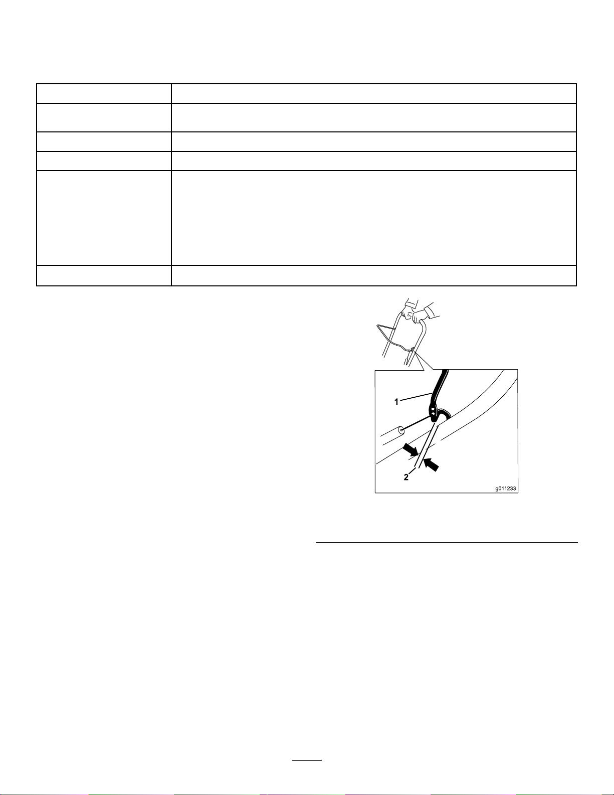
Vedlikehold
Anbefaltvedlikeholdsplan
VedlikeholdsintervallVedlikeholdsprosedyre
Etterførstetime
Etterde2førstetimene
Forhverbrukellerdaglig
Årlig
Årligellerførlagring
•Kontrollerstyrekabelen,ogjusterdenomnødvendig.
•Kontrolleralleløsefester,ogstramdemomnødvendig.
•Skiftmotoroljen.
•Sjekkmotoroljenivået,ogfyllpåoljeetterbehov .
•Kontrollerstyrekabelen,ogjusterdenomnødvendig.
•Undersøkrotorbladeneoglaetautorisertserviceverkstedbytteutrotorbladeneog
skrapenomnødvendig.
•Skiftmotoroljen.
•Overhaltennpluggen,ogerstattomnødvendig.
•Kontrolleralleløsefester,ogstramdemomnødvendig.
•Laetautorisertserviceverkstedundersøkedrivremmen,ogbyttdenuthvisdet
ernødvendig.
•Klargjøremaskinenforoppbevaring.
Sikkerhetvedvedlikehold
Lesdefølgendesikkerhetsforholdsregleneførdu
utførervedlikeholdpåmaskinen:
•Slåavmotoren,tautnøkkelenogventtil
allebevegeligedelerstopperførduforlater
førerposisjonen.Lamaskinenkjølesnedfør
justering,service,rengjøringelleroppbevaring.
•Haalltidpådegvernebrillerellerverneskjerm
vedutføringavenjusteringellerreparasjon,for
åbeskytteøynenefrafremmedlegemersomkan
kastesframaskinen.
•Undersøkallefesteneregelmessigforåseom
tiltrekningsmomenteterriktig,slikatduersikker
påatmaskinenertryggåbruke.
•Dumåikkeendreinnstillingenavmotorregulatoren
imotoren.
Kjøputelukkendeoriginalereservedelerog
tilbehørfraToro.
Kontrollereogjustere
styrekabelen
Kontrollerestyrekabelen
g011233
Figur17
1.Kontrollbøyle2.2–3mmklaring
Merk:Kontrolleratdeterenavstandpå2mmtil
3mmmellomkontrollbøylenoghåndtaket(Figur17).
Viktig:Styrekabelenmåhanoeslakknårdu
koblerfrakontrollbøylenforrotorbladeneforå
stoppehelt.
Serviceintervall:Etterførstetime—Kontroller
styrekabelen,ogjusterdenom
nødvendig.
Årlig—Kontrollerstyrekabelen,ogjusterden
omnødvendig.
Bevegkontrollbøylenbakmothåndtaketforåfjerne
slakkenistyrekabelen(Figur17).
13

Justerestyrekabelen
1.Skyvfjærdekseletoppoghektløsfjærenfra
justeringskoblingen(Figur18).
Figur18
1.Justeringskobling3.Fjærdeksel
2.Z-anordning
Merk:Dukantrekkejusteringskoblingenog
fjærenoppslikatdeterlettereåhekteløs
fjæren.
4.Hektløsfjærenher.
g011232
Figur19
g006402
1.Øvredelavfjæren
2.Settinndenøverstedelen
avfjærenidettehullet
3.Omdreiningspunkt
4.Fjerndenøverstedelen
avfjærenfradettehullet
Merk:Drivremmenkangli(hvine)undervåte
forhold;dufjernerfuktighetfradrivverketved
åstarterotorenogkjøredenutenbelastningi
30sekunder.
2.BevegZ-anordningentilethøyereellerlavere
hullpåjusteringskoblingenforåfåenavstandpå
2til3mmmellomkontrollbøylenoghåndtaket
(Figur18).
Merk:BevegZ-anordningenhøyereforå
minskeavstandenmellomkontrollbøylenog
håndtaket,bevegdetlavereforåøkeavstanden.
3.Festfjærenpåjusteringskoblingenogbeveg
fjærdekseletoverjusteringskoblingen.
4.Kontrollerjusteringen,seKontrollere
styrekabelen(side13).
Merk:Etteromfattendebrukkandethende
atdrivremmenerslitt,ogatdenikkeerstram
nok.Hvisdrivremmenglir(vedvarendehvining)
nårdukjørermedtunglast,koblefjærenfra
justeringskoblingenogyttdenøvredelen
avfjærentilhulletsomerlengrebortefra
omdreiningspunktetikontrollbøylen(Figur19).
Koblesåtilfjærentiljusteringskoblingenog
justerstyringskabelen.
Undersøkerotorbladene
Serviceintervall:Årlig—Undersøkrotorbladeneogla
etautorisertserviceverkstedbytte
utrotorbladeneogskrapenom
nødvendig.
Kontrollerrotorbladeneforslitasjeførhversesong.
Nåreggenpåetrotorbladerslittnedtilslitasjehullet,
laetautorisertserviceverkstedbytteutrotorbladene
ogskraperen(Figur20).
g011544
Figur20
1.Hvisindikatorhulletsom
viserslitasjeerintakt,
trengerduikkeåskifteut
rotorbladene.
14
2.Skiftutrotorbladene
ogskraperenhvis
indikatorhulletforslitasje
vises.

Skiftemotorolje
Serviceintervall:Etterde2førstetimene
Årlig
Hvismulig,lamotorengåinoenminutterforåvarme
oppoljenførduskifterden.Varmoljeyterbedreog
bærermedsegereurenheter.
Spesikasjonerformotorolje
Motoroljekapasitet
OljeviskositetSeFigur23.
API-serviceklassikasjonSJellerhøyere
*Deterrestoljeiveivhusetetteratduhartappet
oljen.Ikkehellheleoljekapasiteteniveivhuset.Fyll
veivhusetmedoljesomanvistifølgendetrinn.
1.Brukenhåndpumpetilåpumpedrivstofffra
drivstofftankenoverienbensinkanne,ellerkjør
motorentildenstanser.
2.Settmaskinenpåenjevnate.
3.Plasseretoljetappefatunderoljetappepluggen,
fjernpluggen,vippsnøfreserenbakoverogtapp
denbrukteoljenioljetappefatet(Figur21).
0,60l*
8.Hellforsiktigoljeioljepåfyllingsrørettilmotoren
er3/4full.
Merk:Dukanvippemaskinenlittforover
(håndtaketopp)forågjøredetenklereåfyllepå
olje.Huskåsettemaskinentilbakeidriftsstilling
førdukontrollereroljenivået.
Viktig:Ikkevippmaskinenheltforovertil
frontenberørerbakken,dadrivstoffkan
lekkeutavmaskinen.
BrukFigur23foråvelgedenbesteoljeviskosi-
tetenforforventetutendørstemperatur.
Figur21
4.Etteratdenbrukteoljenertappet,sett
snøfreserentilbakeidriftsstilling.
5.Monteroljetappepluggen,ogfestdengodt.
6.Rengjøroljelokk/peilestav.
7.Skruutpeilestavenogfjernden(Figur22).
g011606
Figur23
9.Ventitreminuttertiloljenstabiliseresimotoren.
g006372
10.Rengjørpeilestavenmedenrenlle.
11.Medmaskinenidriftsposisjon,settpeilestaven
innioljepåfyllingsrøretutenåskrudeninn,og
trekkdenderetterutigjen.
12.Lesavoljenivåetpåpeilestaven.
•Hvisoljenivåeterforlavt,fyllforsiktigpålitt
oljeioljepåfyllingsrøret,ventitreminutter,og
gjentasåtrinn10tilogmed12,tiloljenivået
påpeilestavenerpåriktignivå.
•Hvisoljenivåetpåpeilestavenerforhøyt,
mådutappeavoljehelttiloljenivåetpå
peilestavenerpåriktignivå.
Viktig:Hvisoljenivåetimotorenerforlavt
ellerforhøyt,ogdukjørermotoren,kan
detteføretilskadepåmotoren.
13.Settpeilestavengodtinnioljepåfyllingsrøret.
14.Tørkoppeventueltdrivstoffsøl.
g006316
Figur22
1.Peilestav
15.Resirkulerdenbrukteoljenpåkorrektmåte.
15

Overhaletennpluggen
Serviceintervall:Årlig—Overhaltennpluggen,og
erstattomnødvendig.
BrukentennpluggavtypenNGKBPR6ESeller
ChampionRN9YC,ellerentilsvarendeplugg.
1.Slåavmotoren,ogventtilallebevegeligedeler
harstanset.
2.Vriutløpssjaktenslikatdenpekerfremover.
3.Fjernutløpssjakten,dettilhørendehåndtaketog
sjakttetningenvedåtautdetrestoreskruene
ogénlitenskrue(Figur24).
g011435
Figur25
Figur24
1.Drivstofftanklokk
2.Storeskruer(tre)5.Sjakttetning
3.Utløpssjakt
4.Litenskrue
4.Fjerndereskruenesomfesterdekselet(Figur
25).
1.Skrue(4)
2.Deksel4.Tennpluggledning
3.Tennplugg
5.Fjerndrivstofftanklokket.
6.Fjerndekselet(Figur25).
g006489
7.Festdrivstofftanklokket.
8.Kobleledningenfratennpluggen.
9.Rengjørrundttennpluggen.
10.Fjerntennpluggenfrasylinderhodet.
Viktig:Entennpluggsomersprukket
ellerskitten,måskiftesut.Ikkerengjør
elektrodene.Partiklersomkommerinni
sylinderenkanføretilatmotorenskades.
11.Justeråpningenpåtennpluggentil0,76mm
somvistiFigur26.
16
1.Midtreelektrodeisolator
2.Elektrodepåsiden
g000533
Figur26
3.Elektrodeavstand(ikke
måltegning)

12.Montertennpluggenogstramtilmedetmoment
på27til30Nm.
13.Kobleledningentiltennpluggen.
Merk:Påseatventilatorslangenliggerriktig
rundttennpluggledningen,somvistiFigur27.
Figur27
Skiftedrivremmen
Hvisdrivremmenblirslitt,gjennomvåttavolje,får
mangesprekker,frynsetekanterellerblirskadetpå
annenmåte,skalremmenskiftesut.
1.Fjerndrivremdekseletvedåfjernedetreboltene
somvistiFigur28.
g011440
1.Ventilatorslange2.Forgasserenstappeskrue
14.Fjerndrivstofftanklokket.
15.Monterdekseletmedskruenedufjernetitrinn4.
Merk:Kontrolleratøvreognedredeksel
passersammenisiderennene.
16.Festdrivstofftanklokket.
17.Montersjakttetningen,utløpssjaktenogdet
tilhørendehåndtaketpåmaskinenvedhjelpav
utstyretdufjernetitrinn3.
Merk:Denlilleskruenpasserinnidet
lillehulletisjakttetningenpåfremsidenav
utløpssjaktåpningen.
Figur28
1.Drivremdeksel6.Drivrem
2.Bolt(3)
3.Rotorskivebolt
4.Bueskive9.Lederull
5.Rotorskive10.Motorremskive
7.Rotoraksel
8.Bremsefjær(hektav
lederullarmenher)
2.Hektløsbremsefjærenfralederullarmenforå
avlasteremmensspenning(Figur28).
3.Fjernskruenogbueskivensomholder
rotorremskiven(Figur28).
4.Fjernrotordrivremmenogdrivremmen(Figur
28).
5.Monterdennyedrivremmen,førdensomvist
iFigur29.
g008238
1.Bremsefjær(monterpå
lederullarmenher)
2.Lederull4.Rotorskive
17
g008317
Figur29
3.Motorremskive

Merk:Førdennyedrivremmenførstrundt
motorremskiven,sålederullenogtilsluttrundt
denløserotorremskivenposisjonertrettover
rotorakselen(Figur28).
6.Monterrotorremskivenpårotorakselen(Figur
28).
7.Monterbueskivenogrotorskiveboltenogtrekk
dengodttil(Figur28).
Merk:Denkonkavesidenavdebueteskivene
skalliggemotyttersidenavremskiven.
8.Monterbremsefjærenpålederullarmen(Figur
29).
9.Monterdrivremdekseletmedboltenedufjerneti
trinn1.
Merk:Påseatdrivremmenerriktigjustertog
fungerer.SeKontrollerestyrekabelen(side13)
ogJusterestyrekabelen(side14).
JustereQuick
Shoot-kontrollen
Hvisdetermerenn13mmslakkiQuick
Shoot-kabelen(Figur30)ellerutløpssjaktenikke
rotererlikemangegraderhvervei(tilvenstreog
høyre),justerQuickShoot-styringskablene.
g006406
Figur31
1.Kabelklemmer
2.StillinnQuickShoot-kontrollenmellomde
topileneplassertpåhøyresideavdetøvre
håndtaket(Figur32).
g006405
Figur32
1.Piler
1.13mmmaksimalslakk
1.Løsnede2QuickShoot-styrekabelklemmene
(Figur31).
3.Roterutløpssjaktenslikatdenpekerrett
fremoverogpilenbakpåutløpssjaktenrettes
innmedpilenpådekselet(Figur33).
g006514
Figur30
18

Figur33
4.Holdutløpssjaktenidennestillingen,trekk
detnedrekabelhusetnedovertildufjerner
slakkenikabelen,ogfestskruenpådennedre
kabelklemmengodt(Figur34).
g006513
Figur35
1.Øvrekabelhus
Merk:Ikkestramkableneformye.Hvis
kabelenerforstram,vilQuickShoot-envære
vanskeligåbruke.
g006521
Figur34
1.Nedrekabelhus
5.Trekkdetøvrekabelhusetfremovertildufjerner
slakkenikabelen,ogfestskruenpådenøvre
kabelklemmengodt(Figur35).
g006512
19

Lagring
Sikkerhetvedoppbevaring
•Slåavmotoren,tautnøkkelenogventtil
allebevegeligedelerstopperførduforlater
førerposisjonen.Lamaskinenkjølesnedfør
justering,service,rengjøringelleroppbevaring.
•Drivstoffgassermegetbrannfarlig,eksplosivog
farligåinnånde.Hvisproduktetoppbevaresi
nærhetenavild,kandrivstoffgassantennesog
forårsakeeneksplosjon.
•Maskinenmåaldrioppbevaresinneihus(bolig),
ikjellerellerpåandrestederderdetnnes
antenningskilder,sliksomvarmtvannsbeholdere
ogvarmeovner,tørketromler/-skap,fyringsanlegg
ogliknende.
•Ikkevippmaskinenforoverellerbakovermed
drivstoffidrivstofftanken,dadrivstoffkanlekkeut
avmaskinen.
•Ikkeoppbevarmaskinenmedhåndtaketvippet
nedpåbakken,fordioljekanlekkeinni
motorsylindreneogpåbakken,ogmotorenvil
kanskjeikkestarte.
10.Sprut10mlmedoljeitennplugghullet.
11.Montertennpluggenforhånd,ogtrekkdentil
medetmomentpå27til30N∙m.
12.Mednøkkelenfjernet,drasaktei
tilbakespolingsstarterenforåfordele
oljenpåinnsidenavsylinderen.
13.Rengjørsnøfreseren.
14.Lakkeravskalledeoveratermedlakksomer
tilgjengeligfraetautorisertserviceverksted.
Pussområdetførlakkeringogbruket
rustforhindrendemiddelforåforhindreat
metalldelerruster.
15.Trekktilalleløsefester.Reparerellerskiftut
ødelagtedeler.
16.Dekktilmaskinen,ogoppbevardenpået
rent,tørtstedsomerutilgjengeligforbarn.La
motorenblikaldførmaskinensettespåetlukket
sted.
Oppbevaresnøfreseren
1.Nårdufyllerpådrivstoffdensistegangen
iåret,blanderdustabiliseringsmiddeli
nyttdrivstoffsomanvistavprodusentenav
stabiliseringsmiddelet.
Viktig:Ikkeoppbevardrivstofflengre
ennanbefaltavprodusentenav
drivstoffstabiliseringsmiddelet.
2.Kjørmotorenitiminutterforåfordelebensinen
medtilsettingsmidletidrivstoffsystemet.
3.Stoppmotoren,ladenavkjøles,ogtøm
drivstofftankenellerkjørtilmotorenstopperav
segselv.
4.Startmotorenigjen,ogkjørdentildenslåsav.
5.Chokeellerprimmotoren,startdenfortredje
gangogkjørmotorentildenikkestarter.
6.T appdrivstoffetiforgasserengjennom
forgasserenstappeskrueogoppiengodkjent
bensinbeholder.
7.Avhendubruktdrivstoffpåkorrektmåte.
Resirkulerisamsvarmedlokaleforskrifter,eller
brukdrivstoffetibilendin.
8.Skiftmotoroljenmensmotorenfortsattervarm.
SeSkiftemotorolje(side15).
9.Fjerntennpluggen.SeOverhaletennpluggen
(side16).
20

PersonvernerklæringforEØS/Storbritannia
Torobrukerpersonopplysningenedine
ToroCompany(«T oro»)respektererdittpersonvern.Nårdukjøpevåreprodukter,vikansamlebestemtepersonopplysningeromdeg,entendirektefra
degellerviadenlokaleT oro-avdelingeneller-forhandleren.Torobrukerdenneinformasjonenforåinnfrikontraktsfestedeforpliktelser–sliksomå
registreregarantiendin,behandlegarantikravetdittellerkontaktedegitilfelleenprodukttilbakekalling–ogtillegitimeforretningsformål–sliksomå
målekundenstilfredshet,forbedreproduktenevåreogutstyredegmedproduktinformasjonsomkanværeavinteresse.Torokandeledininformasjon
medvåredatterselskaper,forhandlereellerandreforretningspartnereiforbindelsemeddisseaktivitetene.Vikanogsåoppgipersonopplysninger
nårdettekrevesunderlovenelleriforbindelsemedsalg,kjøpellersammenslåingavenvirksomhet.Vivilikkeselgepersonopplysningenedinetil
andreselskaperformarkedsføringsformål.
Bevaringavpersonopplysninger
Torovilbevaredinepersonopplysningersålengesomdeterrelevantfordeovennevnteformåleneogisamsvarmedlovfestedekrav .Hvisduvilhamer
informasjonomgjeldendebevaringsperioder,kandukontaktelegal@toro.com.
Torosforpliktelsetilsikkerhet
PersonopplysningenedinekanbehandlesiUSAelleretannetlandsomkanhamindrestrengepersonvernloverennlandetduerbosatti.Når
vioverføreropplysningenedineutenforlandetduerbosatti,vilviiverksettelovfestede,påbudtetiltakforåsikreatdeterpåplassskikkeligevern
sombeskytteropplysningenedineogsikreratdebehandlessikkert.
Tilgangogkorrigering
Dukanharettentilåkorrigereellergjennomgåpersonopplysningenedineellermotsettedegellerbegrensebehandlingenavopplysningenedine.Forå
gjøredettemådukontakteosspåe-postpålegal@toro.com.HvisduharbekymringeromhvordanT oroharbehandletpersonopplysningenedine,
oppfordrervidegtilåtadetteoppdirektemedoss.VæroppmerksompåatbosatteiEuropaharrettentilåklagetildetlokaledatatilsynet.
374-0282RevC


CCR
Modellnr38563—Serienr405012000ochhögre
Modellnr38568—Serienr405012000ochhögre
™
QuickClear™-snöslunga
Introduktion
Dennamaskinäravseddattanvändasav
privatkunder.Denärfrämstkonstrueradföratt
skottasnöfrånstenbelagdaytor,t.ex.uppfarteroch
trottoarer,ochandratrakområdenruntbostäder
ellerkommersiellaanläggningar.Denärinteavsedd
förattforslabortandramaterialänsnö,ellerföratt
rensagrusytor.Detkanmedförafarafördigoch
kringståendeommaskinenanvändsiandrasyften
änvadsomavsetts.
Läsdennainformationnogasåattdulärdigatt
användaochunderhållaproduktenpårättsätt,och
förattundvikaperson-ochproduktskador.Duär
ansvarigförattproduktenanvändspåettkorrektoch
säkertsätt.
Besökwww.Toro.comomdubehöver
utbildningsmaterialförsäkerhetochdrift,
informationomtillbehör,hjälpmedatthittaen
återförsäljareelleromduvillregistreradinprodukt.
Kontaktaenauktoriseradåterförsäljareeller
Toroskundserviceochhamaskinensmodell-och
serienummertillhandsomduharbehovavservice,
Toro-originaldelarellerytterligareinformation.
Figur1visarvardunnermaskinensmodell-och
serienummer.Skrivinnumrenidettommautrymmet.
FormNo.3432-412RevA
Bruksanvisning
g291846
Figur1
1.Modell-ochserienummer
Modellnr
Serienr
Idenhärbruksanvisningenangespotentiellarisker
ochallasäkerhetsmeddelandenharmarkeratsmed
envarningssymbol(Figur2),somangerfarasom
kanledatillallvarligapersonskadorellerdödsfallom
föreskrifternainteföljs.
Viktigt:Skannarutkodenpåserienummerdekalen
(iförekommandefall)medenmobilenhet
förattregistreradinprodukt,fåtillgångtill
informationomgaranti,reservdelarochannan
produktinformation.
©2019—TheToro®Company
8111LyndaleAvenueSouth
Bloomington,MN55420
Registreradinproduktpåwww.Toro.com.
CV
g000502
Figur2
Varningssymbol
Tvåordanvändsocksåidenhärbruksanvisningenför
attmarkerainformation.Viktigtangerspeciellteknisk
informationochObserveraangerallmäninformation
somärvärdattnotera.
Produktenuppfyllerallarelevantaeuropeiskadirektiv.
Merinformationnnsiproduktensseparataförsäkran
omöverensstämmelse.
Viktigt:Omduanvändermaskinenpåenhöjd
över1500munderenkontinuerligperiodskadu
setillattensatsförhöghöjdharmonteratssåatt
motornuppfyllerutsläppskravenfrånCARB/EPA.
Satsenförhöghöjdökarmotornsprestanda,
samtidigtsomdenförhindrarfastnadetändstift,
Översättningavoriginalet(SV)
TrycktiMexiko
Medensamrätt
*3432-412*A

trögstartochhögreutsläpp.Närduharmonterat
satsenskadufästaetikettenförhöghöjdbredvid
serienummersdekalenpåmaskinen.Kontakta
enauktoriseradToro-återförsäljareomduvill
skaffarättsatsförhöghöjdochenetikettför
höghöjdtilldinmaskin.Duhittaråterförsäljare
idinnärhetpåvårwebbplatswww.Toro.com
ellergenomattkontaktaToroskundtjänstpå
denummersomangesigarantiförklaringen
omutsläppsbegränsning.Tabortsatsenfrån
motornochåterställmotorntilldessursprungliga
fabrikskongurationnärmotornkörspålägre
höjdän1500m.Körinteenmotorsomhar
konverteratsföranvändningpåhöghöjdpålägre
höjd.Dåkanmotornöverhettasochskadas.
Omduärosäkerpåommaskinenharkonverterats
föranvändningpåhöghöjdskaduletaefter
följandeetikett(Figur3).
Figur3
decal127-9363
Innehåll
Introduktion...............................................................1
Säkerhet...................................................................3
Allmänsäkerhet..................................................3
Säkerhets-ochinstruktionsdekaler....................4
Montering..................................................................5
1Fällaupphandtaget.........................................5
2Monteringavutkastare....................................5
3Fyllapåoljaimotorn........................................5
4Justerastyrkabeln...........................................6
Produktöversikt.........................................................7
Specikationer...................................................7
Redskap/tillbehör................................................7
Körning.....................................................................7
Förekörning..........................................................7
Säkerhetföreanvändning...................................7
Fyllabränsletanken............................................8
Kontrolleraoljenivånimotorn.............................8
Underarbetetsgång..............................................8
Säkerhetunderanvändning................................8
Startamotorn......................................................9
Kopplainrotorbladen........................................10
Urkopplingavrotorbladen.................................10
Stängaavmotorn..............................................11
Justerautkastarenochstrålriktaren...................11
Rensaenigensattutkastare..............................11
Arbetstips........................................................12
Efterkörning........................................................12
Säkerhetefteranvändning................................12
Förhindrafastfrysningefteranvändning............12
Underhåll................................................................13
Rekommenderatunderhåll..................................13
Säkerhetvidunderhåll......................................13
Kontrolleraochjusterastyrkabeln.....................13
Kontrollerarotorbladen.....................................14
Bytautmotoroljan.............................................15
Utförservicepåtändstiftet................................16
Bytautdrivremmen...........................................17
JusteraQuickShoot-styrsystemet....................18
Förvaring................................................................20
Säkerförvaring.................................................20
Ställamaskineniförvar.....................................20
2

Säkerhet
Maskinenharutformatsienlighetmed
specikationernaiSS-ENISO8437.
Allmänsäkerhet
Maskinenkanslitaavhänderochfötterochkasta
omkringföremål.Följalltidallasäkerhetsanvisningar
förattundvikaallvarligapersonskador.
•Läsochsetillattduharförståttinnehålletiden
härbruksanvisningeninnandustartarmotorn.Se
tillattallasomanvänderdenhärproduktenförstår
varningarna,vethurproduktenskaanvändasoch
vethurmansnabbtstängeravmotorn.
•Stängavmotornnärdulämnarkörpositionen,
oavsettorsak.
•Hållhänderochfötterpåavståndfrånmaskinens
rörligadelar.
•Körendastmaskinenomskyddochandra
säkerhetsanordningarsitterpåplatsochfungerar.
•Hållavståndettillutkastaröppningen.Håll
kringstående,isynnerhetsmåbarn,bortafrån
arbetsområdet.
•Låtaldrigbarnköramaskinen.
3

Säkerhets-och
instruktionsdekaler
Säkerhetsdekalernaoch
anvisningarnaärfulltsynliga
föroperatörenochnnsnäraalla
potentiellafarozoner.Ersättdekaler
somharskadatsellersaknas.
94-2577
1.Hållstyrstångenmothandtagetförattstartarotorbladen.
2.Släppstyrstångenförattstopparotorbladen.
Beställartikelnr117-9121
decal94-2577
Endastmodell38563,beställartikelnr117-6036
117-9102
1.Varning–läs
bruksanvisningen.
2.Kapnings-/avslitningsrisk,
impeller–stängav
motornochväntatills
matarskruvenstannar
innandukliverur
maskinen.
3.Riskförkringygande
föremål–hållkringstående
påavstånd.
4.Explosionsrisk–lutainte
maskinenbakåt.
5.Tändningslås–på
6.Tändningslås–av
7.Snapspump
8.Tryckpåknappentre
gångerförattsnapsa
motorn.
9.Läsbruksanvisningen
innandukontrollerar
motornsoljenivå.
decal117-9102
decal115-5698
115-5698
1.Kapnings-/avslitningsriskiimpellernochmatarskruven–
placeraintehändernaiutkastaren,tautnyckelnochläs
bruksanvisningeninnanunderhållutförs.
Endastmodell38568,beställartikelnr117-6046
117-9103
1.Varning–läs
bruksanvisningen.
2.Kapnings-/avslitningsrisk,
impeller–stängav
motornochväntatills
matarskruvenstannar
innandukliverur
maskinen.
3.Riskförkringygande
föremål–hållkringstående
påavstånd.
4.Explosionsrisk–lutainte
maskinenbakåt.
5.Tändningslås–på
6.Tändningslås–av
7.Snapspump
8.Tryckpåknappentre
gångerförattsnapsa
motorn.
9.Läsbruksanvisningen
innandukontrollerar
motornsoljenivå.
10.Anslutmaskinenförattför
attstartadenelektriska
startmotorn.
decal117-9103
4

Montering
Fällaupphandtaget
Ingadelarkrävs
Tillvägagångssätt
1
g263299
2
Monteringavutkastare
Ingadelarkrävs
Tillvägagångssätt
g262492
5

3
Fyllapåoljaimotorn
Ingadelarkrävs
Tillvägagångssätt
4
Justerastyrkabeln
Ingadelarkrävs
Tillvägagångssätt
SeJusterastyrkabeln(sida14).
g253610
6

Produktöversikt
1.Strålriktarensavtryckare
2.Utkastare9.Nyckel
3.Tanklock
4.Styrstång
5.QuickShoot™-styrsystem
6.Startsnörehandtag
7.Snapspump
Figur7
8.Knapptillelektrisk
10.Choke
11.Oljeavtappningsplugg
12.Påfyllningsrör/oljesticka
13.Strålriktare
startmotor(endast
modellermedelstart)
Körning
Förekörning
Säkerhetföreanvändning
Allmänsäkerhet
•Endastförmodellermedelektriskstart:Använd
förlängningssladdarochkärlenligthandboken.
Inspekteradenelektriskasladdeninnandu
ansluterdentillelnätet.Bytutsladdenomden
harskadats.Kopplabortströmkabelnomduinte
avserattstartamaskinen.
•Användlämpligakläder,inklusiveögonskydd,
g011431
långbyxor,rejälaochhalkfriaskorsamt
hörselskydd.Sättupplångthår,knytfastlöst
sittandeklädesplaggochanvändintelösa
smycken.
•Inspekteranogadetområdedärmaskinenska
användasochplockabortallafrämmandeföremål
såsomdörrmattor,pulkor,plankorochkablar.
•Förekörningskadurepareraellerersätta
eventuellaskydd,säkerhetsanordningareller
dekalersomärtrasiga,oläsligaellersaknas.Se
ocksåtillattallaskruvar,bultarochmuttrarär
åtdragna.
Specikationer
ModellVikt
37kg
38563
(82lb)122cm54cm107cm
39kg
38568
(87lb)
Längd
(48tum)(21tum)(42tum)
Redskap/tillbehör
DetnnsetturvalavgodkändaToro-redskapoch
-tillbehörsomdukananvändaförattförbättraoch
utökamaskinenskapacitet.Kontaktaenauktoriserad
återförsäljareellerauktoriseradT oro-distributör,eller
gåtillwww.Toro.comförattseenlistaöveralla
godkändaredskapochtillbehör.
Användendastoriginalreservdelarochtillbehör
frånT oroförattgaranteraoptimalprestandaoch
fortlöpandesäkerhetförprodukten.Detkanvara
farligtattanvändareservdelarochtillbehörfrånandra
tillverkareochdetkangöraproduktgarantinogiltig.
Bredd
Bränslesäkerhet
Höjd
Bränsleärmycketbrandfarligtochexplosivt.Brand
ellerexplosionibränslekangedigochandra
personerbrännskador.
•Förhindraattstatiskelektricitetantänderbränslet
genomattställabränsledunkenoch/ellermaskinen
påmarkenförepåfyllning,inteiettfordoneller
ovanpåettföremål.
•Fyllbränsletankenutomhus,dåmotornärkall.
Sättpåtanklocketordentligtochtorkaupp
eventuelltutspilltbränsle.
•Hanteraintebränslenärdurökerellerbennerdig
inärhetenavenöppenlågaellergnistor.
•Förvarabränsleiengodkändbränsledunksom
förvarasoåtkomligförbarn.
•Lutamaskinenendastenligtanvisningarnanärdet
nnsbränsleitanken.
•Omduspillerbränslepåklädernamåstedubyta
demomedelbart.
7

Fyllabränsletanken
•Användendastrenochfärsk(ejäldreän30dagar)
blyfribensinmedoktantal87ellerhögreförbästa
resultat(klassiceringsmetod[R+M]/2).
•Syresattabränslenmedupptill10%etanoleller
15%MTBEbaseratpåvolymärgodkända.
•Användinteetanol-bensinblandningar(t.ex.
E15ellerE85)sominnehållermerän10%
etanolbaseratpåvolym.Detkanledatill
prestandaproblemoch/ellerskadorpåmotorn,
vilkaeventuelltinteomfattasavgarantin.
•Användintebensinsominnehållermetanol.
•Förvaraintebränsleibränsletankenellerien
bränsledunkundervinternominteenstabiliserare
används.
•Tillförinteoljaibensinen.
Kontrolleraoljenivånimotorn
Serviceintervall:Varjeanvändningellerdagligen
Fyllintepåöverpåfyllningsröretsnederstadelpå
bränsletanken(Figur8).
g216203
Figur8
Viktigt:Köpbarasåmycketbränslesomgåråt
inomenmånadförbästaresultat.Annarskan
duanvändabränslestabiliserare/konditionerare
imaskinensåattbränsletförblirfärskt
längre.Följanvisningarnafråntillverkarenav
bränslestabiliseraren.
Underarbetetsgång
Säkerhetunderanvändning
Allmänsäkerhet
•Stängavmotorninnandurensarmaskinen
ochanvändalltidenpinne.
•Hålldigbakomhandtagenochhållavståndtill
utkastaröppningennärdukörsnöslungan.Håll
ansikte,händer,fötterochandrakroppsdelar
g293231
Figur9
ochklädesplaggbortafrånrörligaoch
roterandedelar.
•Riktaaldrigutkastarenmotpersonerellermot
områdendärdetkanuppståegendomsskador.
•Varfulltkoncentreradpåmaskinennärdu
använderden.Ägnadiginteåtaktivitetersomkan
distraheradig,eftersompersonskadorellerskador
påegendomdåkanuppstå.
•Varförsiktigsåattduintehalkarellerramlar,
särskiltnärdukörmaskinenbakåt.
•Setillattduharbrafotfästeochhållordentligti
handtaget.Gå!Springaldrig.
8

•Varytterstförsiktignärduanvändermaskineni
sluttningar.
•Körintemaskinenomduhardåligsikteller
belysning.
•Hauppsiktbakåtochvarförsiktignärdubackar
medmaskinen.
•Omdukörpåettfrämmandeföremålskadu
stängaavmotorn,tautnyckelnochundersökaom
maskinenärskadad.Repareraeventuellaskador
innandustartarmaskinen.
•Ommaskinenbörjarvibreraonormaltskadu
genaststängaavmotornochfastställaorsaken.
•Körintemotorninomhus,eftersomavgaserär
•Drivningentillmatarskruvenskavaraurkopplad
närsnöslunganinteanvänds.
•Varytterstförsiktignärduanvändermaskinenpå
stigarellervägbanor.Seuppfördoldafaroroch
trak.
•Göraldrignågrajusteringarmedmotornigång,
medundantagavvadsomangesianvisningarna.
farliga.
•Överbelastaintemaskinengenomattförsökaröja
försnabbt.
•Stängavmotorninnandukliverurförarsätet,innan
durensaruppsamlaren,impellern,rotorneller
utkastarrännansamtvidreparationer,justeringar
ochkontroller.
Startamotorn
Obs:Taavdighandskennärdusnapsarsåattingenluftkankommautursnapshålet.
Viktigt:Snapsaellerchokainteommotornharkörtsochärvarm.Förmycketsnapsningkanöda
motornochgöraattdenintestartar.
Standardmodeller
g257388
Figur10
9

Modellermedelstart
Figur11
Obs:AnvändbaraenUL-listad16gauge-förlängningssladdsomrekommenderasförutomhusbrukochsom
inteärlängreän15m.
VARNING
g257387
Denelektriskasladdenkanskadasochorsakaelektriskastötarellereldsvåda.
Inspekteradenelektriskasladdennogainnanduansluterdentillelnätet.Startaintemaskinen
omsladdenärskadad.Repareraellerbytutdenskadadesladdenomedelbart.Kontaktaen
auktoriseradåterförsäljareförhjälp.
VARFÖRSIKTIG
Omdulämnarmaskinenanslutentilletteluttagkannågonråkastartadenavmisstagoch
skadapersonerellerföremål(endastmodellermedelektriskstart).
Kopplabortdenelektriskasladdenomduinteavserattstartamaskinen.
Kopplainrotorbladen
Hållstyrstångenmothandtagetförattstarta
rotorbladen(Figur12).
Urkopplingavrotorbladen
Släppstyrstångenförattstopparotorbladen(Figur
13).
Figur12
g219303
Figur13
10
g011230

Stängaavmotorn
Stängavmotorngenomattvridanyckelnmotsolstill
detA VSLAGNAläget(Figur14).
Figur14
Justerautkastarenoch
strålriktaren
NärduskajusterautkastarentryckerdupåQuick
Shoot™-styrsystemetsavtryckarepåhandtagets
högrasidaochförreglagetuppellernedlängs
handtaget.Omduyttarnerreglagetlängshandtaget
roterasutkastarenåtvänsterochomdetyttasuppåt
roterasutkastarenåthöger(Figur15).
g011433
g006399
Figur15
Omduvillhöjaellersänkastrålriktarensvinkeltrycker
dupåstrålriktarensavtryckareochyttardenuppåt
ellernedåt(Figur16).
Figur16
1.Strålriktarensavtryckare2.Strålriktare
Rensaenigensattutkastare
Såhärrensarduutkastaren:
•Stängavmotorn.
•Väntai10sekundertillsduärsäkerpåatt
rotorbladenharstannat.
•Användalltidettrensningsverktyg,aldrig
händerna.
11
g006398

Arbetstips
•Vridutkastarenåtvänsterochhögerförattfrigöra
denfråneventuellisbildning.
VARNING
Stenar,leksakerochandrafrämmande
föremålkanslungasutfrånrotorbladenoch
skadadigellerkringståendeallvarligt.
•Hållområdetsomskaröjasfrittfrån
föremålsomkanplockasuppochslungas
omkringavrotorbladen.
•Hållbarnochhusdjurpåavståndfråndet
områdesomskaröjas.
•Röjsnönsåsnartsommöjligteftersnöfallet.
•Låtstråkenöverlappavarandraföreffektiv
snöröjning.
•Låtsnönslungasutmotlänärsåärmöjligt.
•Ommaskinenintedriversigsjälvframåtpåhala
underlagelleritungsnö,skaduförahandtaget
framåtmenlåtamaskinenarbetaisinegentakt.
•Maskinenkanavlämnagummimärkenpå
nyborstadellerljusbetong.Testapåenavsides
ytaföreanvändning.Dessamärkenärinte
permanenta.
•Närduhartagitutnyckelndrardui
startsnörehandtageteragånger,ellerkopplar
denelektriskasladdentillettelektrisktuttag
ochmaskinen,ochtryckerpådenelektriska
startmotornsstartknappengångförattundvika
attstartsnöretoch/ellerdenelektriskastartmotorn
fryserfast(endastmodellermedelektrisk
startmotor).
•Undersnöigaochkallaväderförhållandenkan
vissareglageochrörligadelarfrysafast.Använd
inteförmycketkraftförattförsökamanövrera
reglagesomharfrusitfast.Startamotornochlåt
dengånågraminuteromduharproblemmedatt
manövreraettreglageellerendel.
Efterkörning
Säkerhetefteranvändning
Allmänsäkerhet
•Förvaraaldrigmaskinenmedbränsleitankeni
enbyggnaddärdetnnsgnistkällor,somt.ex.
varmvattenberedare,värmeelementochtorkskåp.
Låtmotornsvalnainnanmaskinenställsundani
ettslutetutrymme.
•LäsavsnittetFörvaring(sida20)förvadsomgäller
ommaskinenställsiförvaringimerän30dagar.
•Fortsättatthamaskinenpåslagenettparminuter
efteranvändningsåattuppsamlarenochrotorn
intefryserfast.
Förhindrafastfrysningefter
användning
•Låtmotornvarapåslagenettparminuterföratt
förhindraattrörligadelarfryserfast.Stängav
motorn,väntatillsallarörligadelarharstannatoch
tasedanbortisochsnöfrånsnöslungan.
•Rensaborteventuellsnöochisfrånutkastarens
nederdel.
12

Underhåll
Rekommenderatunderhåll
UnderhållsintervallUnderhållsförfarande
Efterdenförstatimmen
Efterdeförsta2timmarna
Varjeanvändningeller
dagligen
Årligen
Årligenellerföreförvaring
•Kontrollerastyrkabelnochjusteradenvidbehov.
•Kontrollerafästelementenochdraåtdemomdeärlösa.
•Bytutmotoroljan.
•Kontrolleramotoroljenivånochfyllpåvidbehov .
•Kontrollerastyrkabelnochjusteradenvidbehov.
•Kontrollerarotorbladenochlåtenauktoriseradåterförsäljarebytautdemoch
skrapanvidbehov.
•Bytutmotoroljan.
•Utförservicepåtändstiftetochbytutdetvidbehov.
•Kontrollerafästelementenochdraåtdemomdeärlösa.
•Låtenauktoriseradåterförsäljareinspekteradrivremmenochbytautdenvidbehov.
•Förberedmaskinenförförvaring.
Säkerhetvidunderhåll
Läsföljandesäkerhetsföreskrifterinnanduutförnågot
underhållpåmaskinen.
•Stängavmotorn,tautnyckelnochväntatills
allarörligadelarharstannatinnandukliverur
förarsätet.Låtmaskinensvalnainnandujusterar,
rengör,förvararellerutförunderhållpåden.
•Användalltidskyddsglasögonellerögonskyddvid
justeringochreparationförattskyddaögonen
frånfrämmandeföremålsomkankastasivägav
maskinen.
•Kontrolleraregelbundetattallafästelementär
korrektåtdragnasåattmaskinenärisäkert
bruksskick.
•Ändraintemotornsvarvtalsinställningar.
KöpendastTorosoriginalreservdelarochtillbehör.
Kontrolleraochjustera
styrkabeln
Kontrollerastyrkabeln
Serviceintervall:Efterdenförstatim-
men—Kontrollerastyrkabeln
ochjusteradenvidbehov.
Årligen—Kontrollerastyrkabelnochjusteraden
vidbehov.
g011233
Figur17
1.Styrstång2.mellanrumpå2–3mm
Obs:Kontrolleraattdetnnsettmellanrumpå
2–3mmmellanstyrstångenochhandtaget(Figur17).
Viktigt:Styrkabelnmåstehaettvisstslacknärdu
släpperstyrstångenförattrotorbladenskakunna
stannanormalt.
Förstyrstångentillbakamothandtagetförattfåbort
slacketistyrkabeln(Figur17).
13

Justerastyrkabeln
1.Skjutuppfjäderkåpanochhakalossfjädernfrån
justerlänken(Figur18).
Figur18
1.Justerlänk
2.Z-inpassning
Obs:Dukandrauppjusterlänkenochvajern
förattunderlättalossandetavfjädern.
2.FlyttaZ-inpassningentilletthögreellerlägre
hålijusterlänkenefterbehovföratterhålla
mellanrummetpå2–3mmmellanstyrstången
ochhandtaget(Figur18).
Obs:OmZ-inpassningenyttasupp,
minskasmellanrummetmellanstyrstången
ochhandtaget.Omdenyttasnedökar
mellanrummet.
3.Hakafastfjädernpåjusterlänkenochskjutdit
fjäderkåpanöverjusterlänken.
4.Kontrollerajusteringen;seKontrollerastyrkabeln
(sida13).
3.Fjäderkåpa
4.Hakalossfjädernhär.
g011232
Figur19
g006402
1.Fjädernsövreände3.Vridpunkt
2.Sättidenövreändenav
fjädernidethärhålet
4.Tabortdenövreändenav
fjädernfråndethärhålet
Obs:Remmenkanslira(gnissla)vidvåta
förhållanden.Torkautdrivsystemetgenomatt
startarotornochköradenutanbelastningi
30sekunder.
Kontrollerarotorbladen
Serviceintervall:Årligen—Kontrollerarotorbladen
ochlåtenauktoriseradåterförsäljare
bytautdemochskrapanvidbehov.
Kontrollerarotorbladenförevarjearbetspasssåattde
inteärslitna.Enauktoriseradåterförsäljareskabyta
utdetrerotorbladenochskrapannäreggenpåett
rotorbladharslititsnedtillslitageindikatorhålet(Figur
20).
Obs:Närsnöslunganharanväntsenlängre
tidkandrivremmenblislitenochförlorasin
ursprungligaremspänning.Omdrivremmen
slirar(ochmanhörettoavbrutetgnisslande)
vidtungbelastninglossardufjädernfrån
justerlänkenochyttarfjädernsöverände
tilldethålsomärlängstfrånstyrstångens
vridpunkt(Figur19).Hakadärefterfastfjäderni
justerlänkenochjusterastyrkabeln.
14
1.Rotorbladenbehöver
intebytasuteftersom
slitageindikatorhåletär
intakt.
g011544
Figur20
2.Rotorbladenochskrapan
måstebytasuteftersom
slitageindikatorhåletär
frilagt.

Bytautmotoroljan
Serviceintervall:Efterdeförsta2timmarna
Årligen
Körommöjligtmotorninågraminuterföreoljebytet
förattvärmaoljan.Varmoljarinnerlättareochför
medsigmerföroreningar.
Motoroljespecikationer
Motoroljekapacitet
OljeviskositetSeFigur23.
API-klassiceringSJellerhögre
0,60liter*
*Detnnsöverskottsoljaivevhusetefterattdutömtut
oljan.Hällinteifulltmedoljaivevhuset.Fyllvevhuset
medoljaenligtanvisningarnaiföljandesteg.
1.Pumpabränsletfrånbränsletankentillen
godkändbränsledunkellerkörmotorntillsden
stängsav.
2.Flyttasnöslungantillettplantunderlag.
3.Placeraettavtappningskärlunderoljepluggen
ochskruvasedanuroljepluggenochluta
maskinenbakåtinnandutömmerutden
användaoljanikärlet(Figur21).
g006316
Figur22
1.Oljesticka
8.Fylllångsamtoljepåfyllningsröretmedcatre
fjärdedelaravdenmängdoljasomrymsi
motorn.
Obs:Dukanlutamaskinenliteframåt
(handtagetupp)sågårdetlättareattfyllapå
olja.Komihågattställamaskinenplantinnan
dukontrolleraroljenivån.
Viktigt:Lutaintemaskinensålångtframåt
såattdenbalanserarpånoseneftersom
bränsledåkanläckauturmaskinen.
AnvändFigur23förattväljarättoljeviskositet
fördetförväntadeutomhustemperaturintervallet.
Figur21
4.Närduhartömturoljanåterställerdumaskinen
tillarbetsläge.
5.Sätttillbakaoljepluggenochdraåtden
ordentligt.
6.Görrentruntoljestickan.
7.Skruvalossoljestickanochavlägsnaden(Figur
22).
g006372
g011606
Figur23
9.Väntaitreminutertillsoljanharlagtsigimotorn.
10.T orkaavoljestickanmedenrentrasa.
11.Närmaskinenäridriftlägetsätterduioljestickan
ioljepåfyllningsröretutanattskruvafastden.
Tasedanutoljestickanigen.
12.Läsavoljenivånpåoljestickan.
•Omoljestickanvisarattoljenivånärförlåg
fyllerduförsiktigtpåliteoljaipåfyllningsröret,
15

väntaritreminuterochuppreparsteg10till
12tillsoljestickanvisarkorrektnivå.
•Omoljestickanvisarattoljenivånärförhög
tapparduutöverödigoljatillsoljestickan
visarkorrektnivå.
Viktigt:Ommotornkörsnäroljenivåni
motornärförlågellerförhögkanmotorn
skadas.
13.Sätttillbakaoljestickanipåfyllningsröret
ordentligt.
14.T orkauppallutspilldolja.
15.Lämnainoljanpågodkändåtervinningsstation.
Utförservicepåtändstiftet
Serviceintervall:Årligen—Utförservicepåtändstiftet
ochbytutdetvidbehov.
AnvändetttändstiftavtypenNGKBPR6ESeller
ChampionRN9YCellermotsvarande.
1.Stängavmotornochväntatillsallarörligadelar
harstannat.
2.Roterautkastarensåattdenärriktadframåt.
3.T abortutkastaren,utkastarhandtagetoch
utkastarenstätninggenomatttabortdetre
storaskruvarnaochdenlillaskruven(Figur24).
Figur25
1.Skruv(4)
2.Skydd
3.Tändstift
4.Tändkabel
5.T aborttanklocket.
6.T aborthöljet(Figur25).
7.Skruvapåtanklocket.
8.Lossakabelnfråntändstiftet.
9.Rengörrunttändstiftet.
10.Skruvaborttändstifteturcylindertoppen.
Viktigt:Ettsprucket,skadatellersmutsigt
tändstiftmåstebytasut.Rengörinte
elektrodernaeftersomagorkantasigini
cylindernochorsakaskadorpåmotorn.
11.Ställingapetpådetnyastiftettill0,76mmenligt
Figur26.
g011435
Figur24
1.Tanklock4.Litenskruv
2.Storaskruvar(3)
3.Utkastare
5.Utkastartätning
4.T abortdefyraskruvarsomhållerfasthöljet
(Figur25).
g006489
g000533
Figur26
1.Mittelektrodinsulator
2.Sidoelektrod
16
3.Luftgap(ejiskala)

12.Sättfasttändstiftetochdraåtdettillettmoment
på20–27Nm.
13.Ansluttändkabelntilltändstiftet.
Obs:Kontrolleraattventilationsröretdras
ovanförtändkabelnenligtFigur27.
Figur27
1.Ventilatorrör2.Förgasarens
avtappningsskruv
14.T aborttanklocket.
15.Sättdithöljetmedskruvarnasomdutogbort
isteg4.
Obs:Kontrolleraattdetövreochnedrehöljet
passarihopisidospåren.
Bytautdrivremmen
Bytdrivremmenomdenharblivitsliten,oljeindränkt,
sprucken,nöttellerfåttandraskador.
1.T abortdrivremskåpangenomattlossadetre
skruvarnaenligtFigur28.
g011440
g008238
Figur28
1.Drivremmenskåpa
2.Skruv(3)
3.Rotorskivansskruv
4.Böjdbricka
5.Rotorskiva10.Motorremskiva
6.Drivrem
7.Rotorspindel
8.Bromsfjäder(hakaloss
frånmellandrevsarmen
här)
9.Mellanremskiva
16.Skruvapåtanklocket.
17.Sättfastutkastarenstätning,utkastaren
ochutkastarhandtagetpåmaskinenmedde
fästelementsomdutogbortisteg3.
Obs:Denlillaskruvensättsidetlillahåleti
tätningenpåutkastaröppningensframsida.
2.Hakalossbromsfjädernfrånmellandrevsarmen
förattminskaremspänningen(Figur28).
3.Lossaskruvenochdenböjdabrickansomhåller
fastrotorskivan(Figur28).
4.T abortrotorskivanochdrivremmen(Figur28).
5.MonteradennyadrivremmenenligtFigur29.
Figur29
1.Bromsfjäder(monterapå
mellandrevsarmenhär)
2.Mellanremskiva4.Rotorskiva
3.Motorremskiva
g008317
Obs:Draförstdennyadrivremmenrunt
motorremskivan,runtmellanremskivanoch
17

slutligenruntdenlösarotorskivanprecisovanför
rotorspindeln(Figur28).
6.Monterarotorskivanpårotorspindeln(Figur28).
7.Monteradenböjdabrickanochrotorskivans
skruv,ochdraåtordentligt(Figur28).
Obs:Deböjdabrickornaskonkavasidapassar
motskivansutsida.
8.Monterabromsfjädernpåmellandrevsarmen
(Figur29).
9.Monteradrivremmenskåpamedskruvarnasom
dutogbortisteg1.
Obs:Kontrolleraattdrivremmenärkorrekt
justeradochattdenfungerar.SeKontrollera
styrkabeln(sida13)ochJusterastyrkabeln(sida
14).
JusteraQuick
Shoot-styrsystemet
StällinQuickShoot-reglagevajrarnaomdetnnsmer
än13mmslackiQuickShoot-vajern(Figur30)eller
omutkastareninteroterartillsammavinkelåthöger
ochvänster.
g006406
Figur31
1.Kabelklämmor
2.PlaceraQuickShoot-reglagetmellandetvå
pilarnapådetövrehandtagetshögrasida(Figur
32).
Figur30
1.13mmmaximaltslack
1.LossadetvåklämmornapåQuick
Shoot-reglagevajern(Figur31).
g006405
Figur32
1.Pilar
3.Vridutkastarensåattdenärriktadraktframåt
ochsåattpilenpåutkastarensbaksidaliggeri
g006514
linjemedpilenpåhöljet(Figur33).
18

4.Hållutkastarenraktframåt,dradetnedre
vajerhöljetnedåttillsvajernspännsochdraåt
skruvenpådennedrevajerklämmanordentligt
(Figur34).
Figur34
1.nedrevajerhölje
g006512
Figur33
g006521
5.Dradetövrevajerhöljetframåttillsvajernspänns
ochdraåtskruvenpådenövrevajerklämman
ordentligt(Figur35).
g006513
Figur35
1.Övrevajerhölje
19

Obs:Spännintevajrarnaförhårt.Omvajrarna
spännsförhårtblirdetsvårtattanvändaQuick
Shoot.
Förvaring
Säkerförvaring
•Stängavmotorn,tautnyckelnochväntatills
allarörligadelarharstannatinnandukliverur
förarsätet.Låtmaskinensvalnainnandujusterar,
rengör,förvararellerutförunderhållpåden.
•Bränsleångorärmycketlättantändliga,explosiva
ochfarligaattandasin.Omduförvarar
produkteniettutrymmemedenöppenlåga
kanbränsleångornaantändasochorsakaen
explosion.
•Förvaraintemaskinenietthus(bostad),källare
ellernågotannatutrymmedärdetnnsgnistkällor
somt.ex.varmvattenberedare,värmeelement,
torkskåp,pannorochliknande.
•Lutaintemaskinenframåtellerbakåtnärdetnns
bränsleibränsletanken.Detkanläckautbränsle
urmaskinen.
•Förvaraintemaskinenmedhandtagetlutatmot
marken,oljakandåläckainimotorcylindernoch
utpåmarken,vilketkanledatillattmotorninte
kanstartas.
Ställamaskineniförvar
1.Närduskafyllapåbränsleförsista
gångenunderaktuellsäsongskadutillsätta
bränslestabiliseraretillfärsktbränsleenligt
anvisningarnafrånbränslestabiliserarens
tillverkare.
Viktigt:Förvaraintebränslelängreänvad
bränslestabiliserartillverkarenanger.
2.Låtmotorngåitiominutersåattdetstabiliserade
bränsletfördelasibränslesystemet.
3.Stängavmotorn,låtdensvalnaochtappaur
bränsletankenellerkörmotorntillsdenstängs
av.
4.Startamotornochkördentillsdenstängsav.
5.Chokaellersnapsamotorn,startadenentredje
gångochkörtillsdenintestartarigen.
6.T appaavförgasarbränsletgenomförgasarens
avtappningsskruvochiniettgodkäntbensinkärl.
7.Kasseraoanväntbränslepålämpligtsätt.
Lämnainbränslespilltillåtervinningelleranvänd
detibilen.
8.Bytmotoroljanmedanmotornfortfarandeär
varm.SeBytautmotoroljan(sida15).
9.Avlägsnatändstiftet,seUtförservicepå
tändstiftet(sida16).
10.Sprutain10ml(tvåteskedar)oljai
tändstiftshålet.
20

11.Monteratändstiftetförhandochskruvasedanåt
dettill27–30N∙m.
12.Närduhartagitutnyckelndrardulångsamt
istartsnörehandtagetsåattoljanfördelaspå
cylindernsinsida.
13.Rengörmotorn.
14.Målailackskadormedfärgsomduköptfrånen
auktoriseradåterförsäljare.Slipaskadadeytor
innandumålardemochanvändrostskyddså
attmetalldelarnainterostar.
15.Setillattallaskruvar,bultarochmuttrarär
åtdragna.Repareraellerbytutskadadedelar.
16.Täckövermaskinenochförvaradenpåenren,
torrplatsutomräckhållförbarn.Låtmotorn
svalnainnanmaskinenställsundaniettslutet
utrymme.
21

IntegritetsmeddelandeförEES/STORBRITANNIEN
Torosbrukavdinapersonuppgifter
TheToroCompany(”T oro”)respekterardinintegritet.Isambandmeddinaköpavvåraprodukterkanvisamlainvissapersonuppgifteromdig,antingen
direktfråndigellerviadinlokalaT oro-återförsäljare.T oroanvänderdessauppgiftertillattutförasinaskyldigheterenligtavtalet(t.ex.registreradin
garanti,behandladinagarantianspråkellerkontaktadigihändelseavattenproduktmåsteåterkallas)ochföratttillfredsställalegitimaaffärsändamål
(t.ex.mätakundnöjdhet,förbättravåraprodukterellertillhandahållaproduktinformationsomkanvaraavintressefördig).T orokanvidarebefordra
uppgifternatillsinadotterbolag,återförsäljareellerandraaffärspartnersisambandmednågonavdessaaktiviteter.Vikanävenvidarebefordra
personuppgifteridefallsomlagenkräverdetellerisambandmedförsäljning,köpellerfusionavettföretag.Visäljerintedinapersonuppgifteri
marknadsföringssyftetillnågotannatföretag.
Behållandeavdinapersonuppgifter
Torobehållerdinapersonuppgiftersålängedeärrelevantaförovannämndasyftenochenligtgällandelag.Kontaktalegal@toro.comförytterligare
informationomtillämpligaperioderförbehållande.
Torosengagemangförskydd
DinapersonuppgifterkanbearbetasiUSAellerettannatlandsomkanhamindrestriktadataskyddslagarändetlandivilketduärbosatt.Idefallsomvi
överföruppgifterfråndetlandivilketduärbosatt,vidtarvilagstadgadeåtgärderföratttillförsäkraattdinauppgifterskyddasochbehandlaskondentiellt.
Åtkomstochkorrigering
Dukanägarättattkorrigeraellergåigenomdinapersonuppgiftersamtnekaellerbegränsabehandlingenavdinauppgifter.Omduönskargöradetska
dukontaktaossviae-postpålegal@toro.com.OmduharfrågorrörandedetsättpåvilketT oroharhanteratdinauppgifter,uppmanarvidigattdiskutera
detdirektmedoss.Observeraatteuropeiskamedborgareägerrättattlämnainklagomåltillavseddmyndighetfördataskydd.
374-0282RevC
 Loading...