

Page 1

POWER SHIFT SNOWTHROWER SERVICE MANUAL
Table of Contents – Page 1 of 5
ABOUT THIS MANUAL
SAFETY INSTRUCTIONS
FOR YOUR SAFETY...
IDENTIFICATION
MODEL AND SERIAL NUMBERS
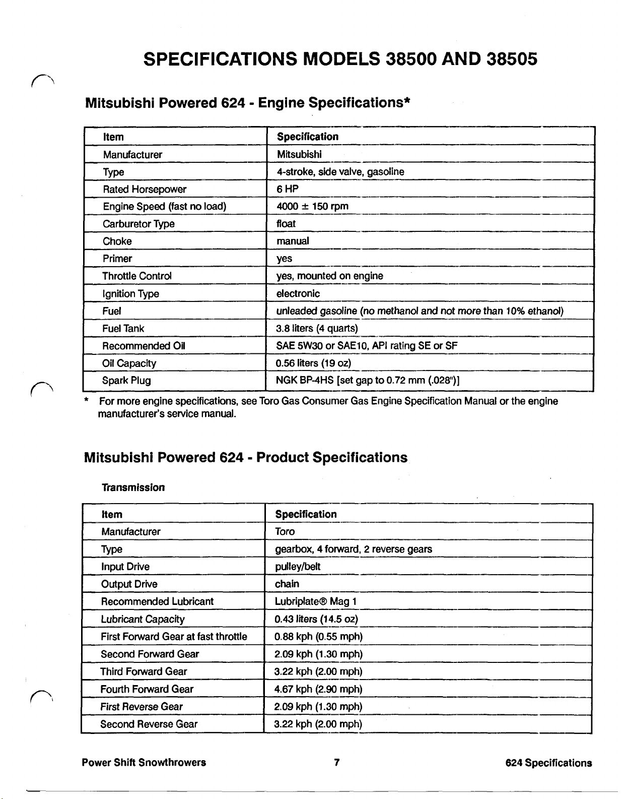
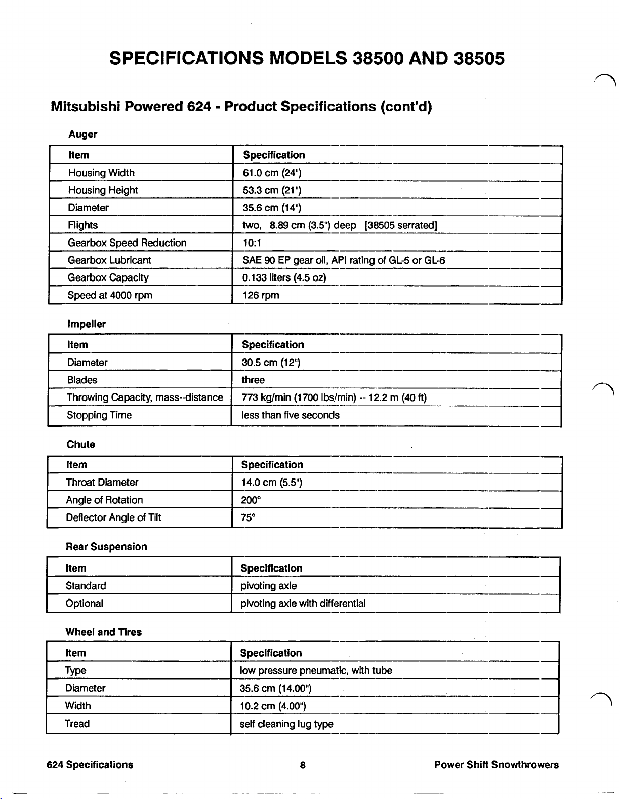
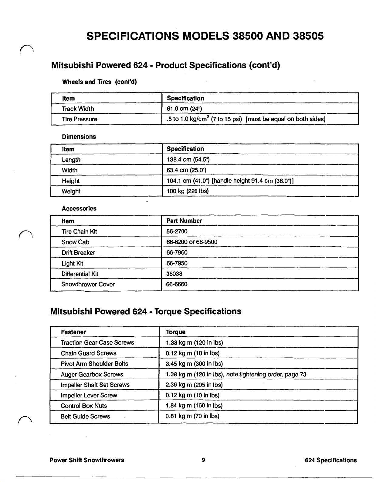
SPECIFICATIONS MODELS 38500 AND 38505
MITSUBISHI POWERED 624 - ENGINE SPECIFICATIONS*
MITSUBISHI POWERED 624 - PRODUCT SPECIFICATIONS
MITSUBISHI POWERED 624 - TORQUE SPECIFICATIONS
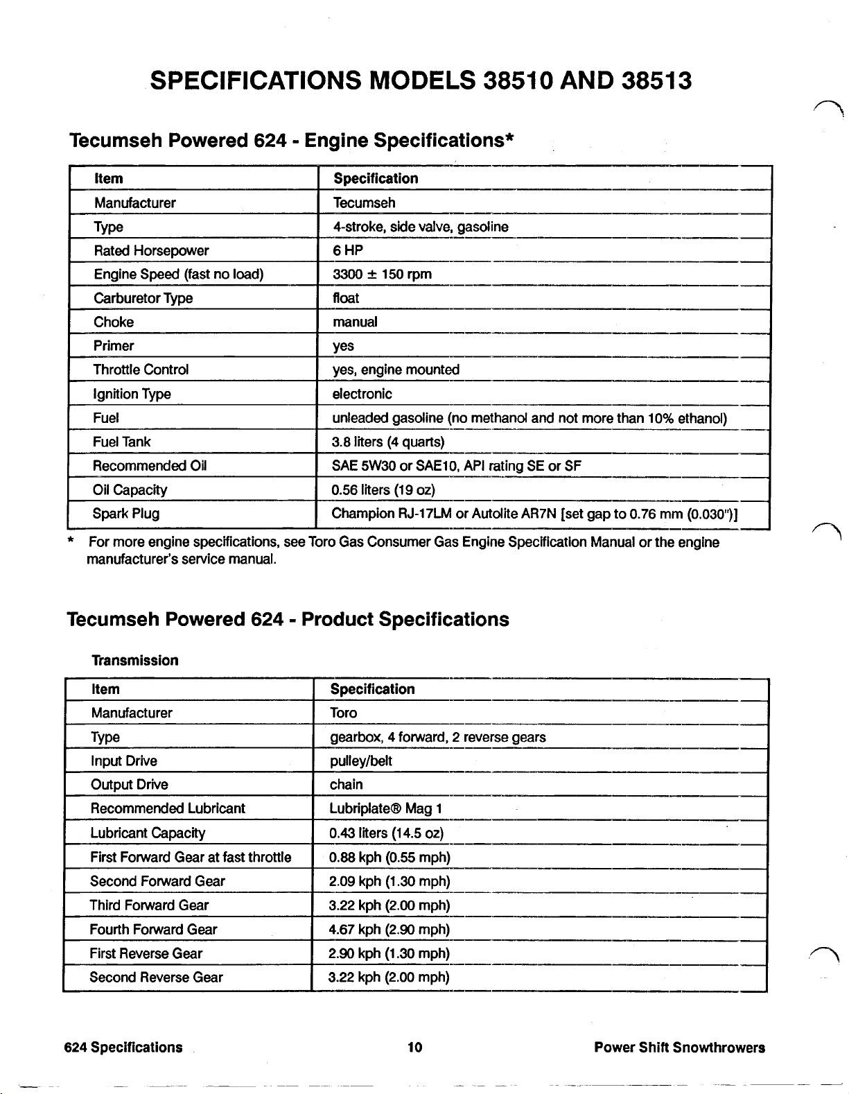
SPECIFICATIONS MODELS 38510 AND 38513
TECUMSEH POWERED 624 - ENGINE SP ECIFIC ATIONS*
TECUMSEH POWERED 624 - PRODUCT SPECIFICATIONS
TORQUE SPECIFICATIONS
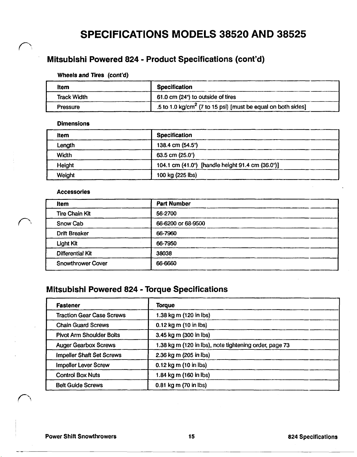
SPECIFICATIONS MODELS 38520 AND 38525
MITSUBISHI POWERED 824 - ENGINE SPECIFICATIONS*
MITSUBISHI POWERED 824 - PRODUCT SPECIFICATIONS
MITSUBISHI POWERED 824 - TORQUE SPECIFICATIONS
SPECIFICATIONS MODELS 38540 AND 38543
TECUMSEH POWERED 824 - ENGINE SP ECIFIC ATIONS*
TECUMSEH POWERED 824 - PRODUCT SPECIFICATIONS
TECUMSEH POWERED 824 - TORQUE SPECIFICATIONS
SPECIFICATIONS MODEL 38545
MITSUBISHI POWERED 828 - ENGINE SPECIFICATIONS*
MITSUBISHI POWERED 828 - PRODUCT SPECIFICATIONS
MITSUBISHI POWERED 828 - TORQUE SPECIFICATIONS
SPECIFICATIONS MODEL 38570
BRIGGS AND STRATTON POWERED 828 - ENGINE SPECIFICATIONS*
BRIGGS AND STRATTON POWERED 828 - PRODUCT SPECIFICATIONS
BRIGGS AND STRATTON POWERED 828 - TORQUE SPECIFICATIONS
SPECIFICATIONS MODEL 38573
TECUMSEH POWERED 828 - ENGINE SP ECIFIC ATIONS*
TECUMSEH POWERED 828 - PRODUCT SPECIFICATIONS
TECUMSEH POWERED 828 - TORQUE SPECIFICATIONS
Page 2

POWER SHIFT SNOWTHROWER SERVICE MANUAL
Table of Contents – Page 2 of 5
SPECIFICATIONS MODELS 38565 AND 38580
BRIGGS AND STRATTON POWERED 1132 - ENGINE SPECIFICATIONS*
BRIGGS AND STRATTON POWERED 1132 - PRODUCT SPECIFICATIONS
TORQUE SPECIFICATIONS
SPECIAL TOOLS AND OTHER NECESSITIES
TROUBLESHOOTING
UNIT DOES NOT PROPEL FORWARD
UNIT WILL NOT PROPEL BACKWARD
NEUTRAL NOT IN CORRECT LOCATION
SHIFT LEVER WILL NOT LOCK IN POWER SHIFT OR REVERSE
OPERATOR CAN SHIFT BETWEEN FORWARD AND REVERSE WHILE TRACTION LEVER IS
WHEELS WILL NOT SWING WHEN POWER SHIFTING
MACHINE DOES NOT PROPEL IN A STRAIGHT LINE
ENGINE KILLS WHEN AUGER OR TRACTION ARE ENGAGED
POOR SNOWTHROW ING PERFORMANC E
IMPELLER OR AUGER DOES NOT TURN
TRACTION OR IMPELLER DOES NOT DISENGAGE
CHUTE PLUGS WITH SNOW
SCRAPER CATCHES ON UNEVEN PAVEMENT
SNOWTHROWER LEAVES SNOW BEHIND
RAPID SKID AND SCRAPER W EAR
FRONT END RISES
MAINTENANCE
MAINTENANCE - DRAINING GASOLINE
MAINTENANCE - CHAIN LUBRICATION
MAINTENANCE - CHANGING CRANKCASE OIL
MAINTENANCE - AUGER GEAR BOX OIL SERVICE
MAINTENANCE - IMPELLER DRIVE BELT ADJUSTMENT
MAINTENANCE - TRACTION DRIVE BELT ADJUSTMENT
MAINTENANCE - REPLACING DRIVE BELTS
MAINTENANCE - DRIVE CHAIN ADJUSTMENT
MAINTENANCE - SPARK PLUG SERVICE
PREPARING SNOWTHROWER FOR STORAGE
SECTION I POWER SHIFT CONTROLS
CONTROL BOX OPERATION
OPERATION - LATCH RELEASE MECHANISM
CONTROL BOX OPERATION - REVERSE CONTROL
CONTROL BOX OPERATION - SHIFT LOCKOUT
CONTROL BOX OPERATION - INDEXING MECHANISM
CONTROL BOX SERVICE
CONTROL BOX SERVICE - TESTING
Page 3

POWER SHIFT SNOWTHROWER SERVICE MANUAL
Table of Contents – Page 3 of 5
SECTION I POWER SHIFT CONTROLS - Continued
CONTROL BOX SERVICE - DISASSEMBLY
CONTROL BOX SERVICE - REASSEMBLY
CONTROL BOX SERVICE - INSTALLATION
CONTROL BOX SERVICE - ADJUSTMENTS
SECTION 2 TRACTION AND IMPELLER CONTROLS
OPERATION
OPERATION - IMPELLER CONTROL
OPERATION - IMPELLER LOCKING MECHANISM
TRACTION AND IMPELLER CONTROLS
TRACTION AND IMPELLER CONTROLS - INSPECTION
TRACTION AND IMPELLER CONTROLS - REASSEMBLY
TRACTION AND IMPELLER CONTROLS - TRACTION CABLE ADJUSTMENT
TRACTION AND IMPELLER CONTROLS - IMPELLER CABLE ADJUSTMENT
SECTION 3 DISCHARGE CHUTE
CHUTE CONTROL
DISCHARGE CHUTE
DISCHARGE CHUTE - REMOVAL
DISCHARGE CHUTE - INSTALLATION
SECTION 4 IDLER SYSTEM
IDLER SYSTEM - OPERATION
IDLER SYSTEM - REMOVAL
IDLER SYSTEM - DISASSEMBLY
IDLER SYSTEM - REASSEMBLY
IDLER SYSTEM - INSTALLATION
IDLER SYSTEM - ADJUSTMENT
SECTION 5 PIVOT AND LATCH SYSTEM
PIVOT SYSTEM
PIVOT SYSTEM - REASSEMBLY
LATCH SYSTEM
SECTION 6 TRANSMISSION
TRANSMISSION - OPERATION
TRANSMISSION - REMOVAL
TRANSMISSION - DISASSEMBLY
TRANSMISSION - REASSEMBLY
TRANSMISSION - INSTALLATION
SECTION 7 AUGER
AUGER
Page 4

POWER SHIFT SNOWTHROWER SERVICE MANUAL
Table of Contents – Page 4 of 5
SECTION 8 AUGER GEAR BOX
AUGER GEAR BOX - OPERATION
AUGER GEAR BOX - REMOVAL
AUGER GEAR BOX - DISASSEMBLY
AUGER GEAR BOX - REASSEMBLY
AUGER GEAR BOX - INSTALLATION
SECTION 9 IMPELLER AND PULLEY SYSTEM
IMPELLER AND PULLEY - OPER ATION
IMPELLER AND PULLEY - REMOV AL
IMPELLER AND PULLEY - INST ALL ATION
SECTION 10 FRONT HOUSING
FRONT HOUSING - OPERATION
FRONT HOUSING - INSTALLATION
SKIDS - OPERATION
SKIDS - REMOVAL
SKIDS - INSTALLATION
SCRAPER- OPERATION
SCRAPER- REMOVAL
SCRAPER- INSTALLATION
SECTION 11 CONTROL PANEL AND HANDLES
CONTROL PANEL - OPERATION
CONTROL PANEL - INSTALLATION
HANDLES
RIGHT HANDLE - INSTALLATION
LEFT HANDLE - REMOVAL
LEFT HANDLE- INSTALLATION
SECTION 12 WHEELS, TIRES AND CHAINS
WHEELS - OPERATION
WHEELS - REMOVAL
WHEELS- INSTALLATION
TIRES - OPERATION
TIRES - SERVICE
CHAINS - OPERATION
CHAINS- INSTALLATION
SECTION 13 ENGINES
ENGINES - SERVICE INFORMATION
SECTION 14 DIFFERENTIAL KIT
DIFFERENTIAL KIT - OPERATION
DIFFERENTIAL KIT - REMOVAL
Page 5

POWER SHIFT SNOWTHROWER SERVICE MANUAL
Table of Contents – Page 5 of 5
SECTION 14 DIFFERENTIAL KIT - Continued
DIFFERENTIAL KIT - DISASSEMBLY
DIFFERENTIAL KIT - ASSEMBLY
DIFFERENTIAL KIT- INSTALLAT ION
SECTION 15 LIGHT KIT
LIGHT KIT 66-7930 - OPERATION
LIGHT KIT 66-7930 - TESTING
LIGHT KIT 66-7930 - LAMP REMOVAL
LIGHT KIT 66-7930 - LAMP INSTALLATION
LIGHT KIT 66-7930 - ALTERNATOR REMOVAL
LIGHT KIT 66-9730 - ALTERNATOR INSTALLATION
LIGHT KITS 66-7940 AND 66-7950 - OPERATION
LIGHT KITS 66-7940 AND 66-7950 - LAMP REMOVAL
LIGHT KIT 66-7940 AND 66-7950 - LAMP INSTALLATION
SECTION 16 SNOW CAB
SNOW CAB - OPERATION
SNOW CAB - REMOVAL
SNOW CAB - INSTALLATION
SECTION 17 DRIFT BREAKER
DRIFT BREAKER - OPERATION
DRIFT BREAKER- DISASSEMBLY
DRIFT BREAKER - ASSEMBLY
Page 6
Page 7
ABOUT THIS MANUAL
This service manual was written expressly for the Tor0 624, 824, 828 and
Power Shift Snowthrowers. The Tor0 Company has made every effort to make the
information in this manual complete and correct.
This manual was written with the service technician in mind.
information used most often
information on safety, identification, specifications, special tods, troubleshooting
and maintenance, all in the front third of the manual.
Disassembly, inspection and reassembly procedures are covered in the last
two-thirds of the manual and are grouped by component.
common repair with its own section or sub-section. For example, you will find that
auger service and auger gearbox service are addressed separately.
And,
because the Power Shift Snowthrower
sections will include some component theory. This information can be found at the
front of each service procedure section.
We are hopeful that you will
you have any questions
the following address:
is
up front.
find
this manual a valuable addition to your shop.
or
comments regarding this manual, please contact
The
81II
Lyndale Avenue South
Minneapolis,
As
a result, you will find reference
is
a relatively complex machine, most
Tor0 Company
MN
55420
It
is organized
We
tried
1132
so
that
to cover each
If
us
at
The Tor0 Company reserves the right to change product specifications or this
manual without notice.
@COPYRIGHT
The
Minneapolis,
ALL
Toro
RIGHTS
Company
MN
55420
RESERVED
1989
-USA
Page 8

TABLE
Reference Information Page
OF CONTENTS
I
Safety Instructions
5
Service Procedures
Section
1
Identification
Specifications
Tool Requirements
Troubleshooting
Maintenance
Power Shift Controls Page
control Box Operation
gear selector control
latch release mechanism
reversecontrol
shiftlockout
indexing mechanism
Control Box Service
removal
testing
disassembly
31
32
36
41
41
41
43
43
45
6
7
Section
Power Shift Snowthrowers
2
Traction and Impeller Controls
Operation
Traction and Impeller Controls
reassembly
installation
adjustments
tractioncontrol
impellercontrol
impeller locking mechanism
disassembly
inspection
reassembly
traction cable adjustment
impeller cable adjustment
1
48
49
50
50
50
51
52
52
53
53
Table of Contents
Page 9
TABLE
Service Procedures (cont’d)
OF
CONTENTS
(cont’d)
Section
Section
3
4
Discharge Chute
Chute Control
operation 54
knobremoval
knob installation
upper rod removal
upper rod installation
lower rod removal
lower rod installation
Discharge Chute
operation
removal
installation 56
Idler System
operation 57
removal 57
disassembly
reassembly
installation
adjustment
54
54
54
55
55
55
55
56
57
58
58
59
Section
!
Section 6 Transmission
5
Pivot and Latch System
Pivot System
operation
disassembly
reassembly 61
latch System
disassembly 61
reassembly 62
operation
removal
disassembly
reassembly
installation 67
60
60
63
64
65
Table
of
Contents
2
Power Shift Snowthrowers
Page 10

TABLE-
Service Procedures (cont’d)
Section 7 Auger Page
OF
CONTENTS
(cont’d)
Section
Section
Section 10 Front Housing
8
9
operation
removal
installation 70
Auger Gearbox
operation 71
removal 71
disassembly 71
reassembly 72
Impeller and Pulley System
operation 75
removal 75
installation 76
Front Housing
operation 78
removal 78
installation 78
69
69
Section
11
Skids
operation 78
removal 78
installation 78
Scraper
removal 79
installation 79
Control Panel and Handles
Control Panel
operation
removal
installation
Handles
right handle removal 81
right handle installation
left handle removal
left handle installation
80
80
80
82
83
84
Power
Shift
Snowthrowers
3
Table
of
Contents
Page 11

TABLE
Service Procedures (cont’d)
OF
CONTENTS
(cont’d)
Section 12
Section
Section 14
Section
13
15
Wheels and Tires
wheels
tires
chains
Engines
servicing information 87
Differential
Light
Light
Kii
Kit
operation 88
removal 88
disassembly 88
reassembly
installation
Kit
66-7930
operation 91
testing 91
lampremoval 91
lamp installation 92
alternator removal 92
alternator installation
Page
85
85
86
89
89
92
Table
Section
Section 17
of
Contents
16
Light
Kits
66-7940 and 66-7950
operation 93
lampremoval
lamp installation
Snow Cab
operation
removal 95
installation
Drift Breaker
operation 98
removal 98
installation 98
4
94
94
95
95
Power Shift Snowthrowers
Page 12
SAFETY
INSTRUCTIONS
Servicing of any outdoor
power' equipment requires
A
statements have been placed thoughout this information on the operation of the Power Shift
manual to enhance safety. Whenever you Snowthrowers.
encounter
instruction because
Failure to comply with the instruction may
result
in
personal injury or death.
I
care and common sense to
prevent injury. "CAUTION"
the
word CAUTION Read the
it
has to do with safety.
FOR
YOUR
This manual is intended as a service and repair manual
only. The safety instructions provided in this manual are
for the troubleshooting and service of the product only.
The individual Operator's Manuals will contain safety
Operator's Manuals with complete operational safety
instruction are available through:
The Toro Company
Publications Department
8111
Lyndale Avenue South
Minneapolis, MN
55420
U.S.A.
SAFETY
Avoid electrocution
Always use a grounded three wire plug and cord when
starting or troubleshooting a snowthrower equipped
with and electric starter.
Avoid possible fires and explosions
Use a container designed for gasoline.
gasoline and never smoke while working around
gasoline.
Avoid fires and falls
Wipe up any spilled fuel or oil.
Avoid lacerations and amputations
Stay clear of all moving parts when running the machine.
Treat all moving parts as
the engine is running or has the potential to start.
Avoid burns
Do not touch engine while running or shortly after
running.
Avoid falls
Do not operate snowthrower at fast speeds on slippery
surfaces.
if
they were moving whenever
Avoid
spilling
Avoid asphyxiation
Never operate an engine in a confined area without
proper ventilation.
Avoid possible eye injuries
Wear eye protection when working with springs or
cables.
Avoid unexpected starting of engine
Always turn
before attempting any cleaning, adjustment or repair.
Avoid accidental misuse of fuel
Always store fuel
that is properly labeled.
Avoid possible injury due to inferior parts
Use only Toro original
safety criteria are met.
Avoid injury to bystanders
Always clear area of bystanders before starting or
testing a snowthrower.
off
key and disconnect spark plug wire
in
a container designed for gasoline
parts
to insure that important
Power Shift Snowthrowers
5
Safety !nstructions
Page 13

Model
and
Serial
Numbers
The snowthrower itself has
a model number and a serial number. The
are stamped on a decal which is located on back
engine mounting plate. These numbers are required number must be included on warranty claims related to
whenever a warranty claim is being filed on a Toro
two
identification numbers: Each engine also has a model and serial number.
two
numbers
of
the location of these numbers. Engine
part.
Consult the engine manufacturers manual for the
model
a failed engine component. This applies even when the
claim is being filed
to
The Toro Company.
and serial
Power Shift Snowthrowers
Page 14
SPECIFICATIONS
MODELS
38500 AND 38505
Mitsubishi Powered 624 Engine Specifications*
I
Choke
Primer
manual
I
--yes
(no methanol and not
r
SAE10,
set gap to
*
For more engine specifications, see Toro Gas Consumer Gas Engine Specification Manual or the engine
manufacturer's service manual.
API
rating
0.72
SE
mm
more
or
SF
(.028')]
than
10%
ethanol)
Mitsubishi Powered 624 Product Specifications
Transmission
Item Specification
Manufacturer
Type
Toro
gearbox, 4 forward, 2 reverse gears
pulley/belt
chain
Lubriplate(R) Mag
-I_
1
Power
Shift
Snowthrowers
0.43
0.88
2.09
3.22
4.67
2.09
3.22
liters
kph
kph
kph
kph
kph
kph
(14.5
(0.55
(1.30
(2.00
(2.90
(1.30
(2.00
7
oz)
mph)
mph)
mph)
mph)
mph)
mph)
624
Specifications
~-
Page 15
SPECIFICATIONS
MODELS
38500 AND 38505
Mitsubishi Powered
Auger
Item
Housing Width
Housing Height
Diameter
Flights
Gearbox Capacity
Impeller
624
Product Specifications (cont'd)
Specification
61
.O
cm
(24)
53.3
cm
(21")
cm
35.6
two,
1O:l
0.133
(14”)
8.89
cm
(3.5")
90
EP
gear oil, API rating
liters
(4.5
oz)
deep
(38505
serrated1
of
GL-5 or GL-6
Chute
Throat Diameter
Angle
of
Rotation
Deflector Angle
Rear Suspension
Item Specification
Standard pivoting axle
Optional pivoting axle with differential
Item Specification
Type low pressure pneumatic, with tube
Diameter
Width
Tread self cleaning lug type
of
Tilt
14.0
200"
75"
35.6
10.2
cm
(5.5")
cm
(14.00")
cm
(4.00")
a
Power
Shift
Snowthrowers
Page 16
SPECIFICATIONS
MODELS
38500
AND
38505
Mitsubishi Powered
Wheels and Tires (cont’d)
Tire Pressure
Dimensions
I
Item
Accessories
624
Product Specifications (cont’d)
Specification
Mitsubishi Powered
Fastener Toque
Traction Gear Case Screws 1.38 kg
-Chain Guard Screws
Pivot
Power Shift Snowthrowers
Arm
Shoulder Bolts
Auger Gearbox Screws 1.38 kg
Control Box
Belt Guide Screws
Nuts
624
Torque Specifications
m
(120
in
Ibs)
m
(10 in
(120 in
(205
(70 in
9
Ibs)
in
Ibs)
Ibs)
Ibs)
Ibs),
Ibs)
0.12 kg
3.45
kg m (300 in
m
2.36 kg
0.12 kg m (10 in
1.84 kg m (160 in Ibs)
0.81 kg
m
m
note tightening order, page 73
624
Specifications
I
Page 17
SPECIFICATIONS MODELS 38510
Tecumseh Powered 624 Engine Specifications*
_I-
AND
38513
*
For more engine specifications, see Toro Gas Consumer Gas Engine Specification Manual or the engine
manufacturer’s service manual.
Tecumseh Powered 624 Product Specifications
Transmission
I
Item
Input Drive pulley/belt
output
Drive chain
Specification
Toro Manufacturer
4
gearbox,
forward, 2 reverse gears
624
Specifications
10
Power
Shift Snowthrowers
Page 18
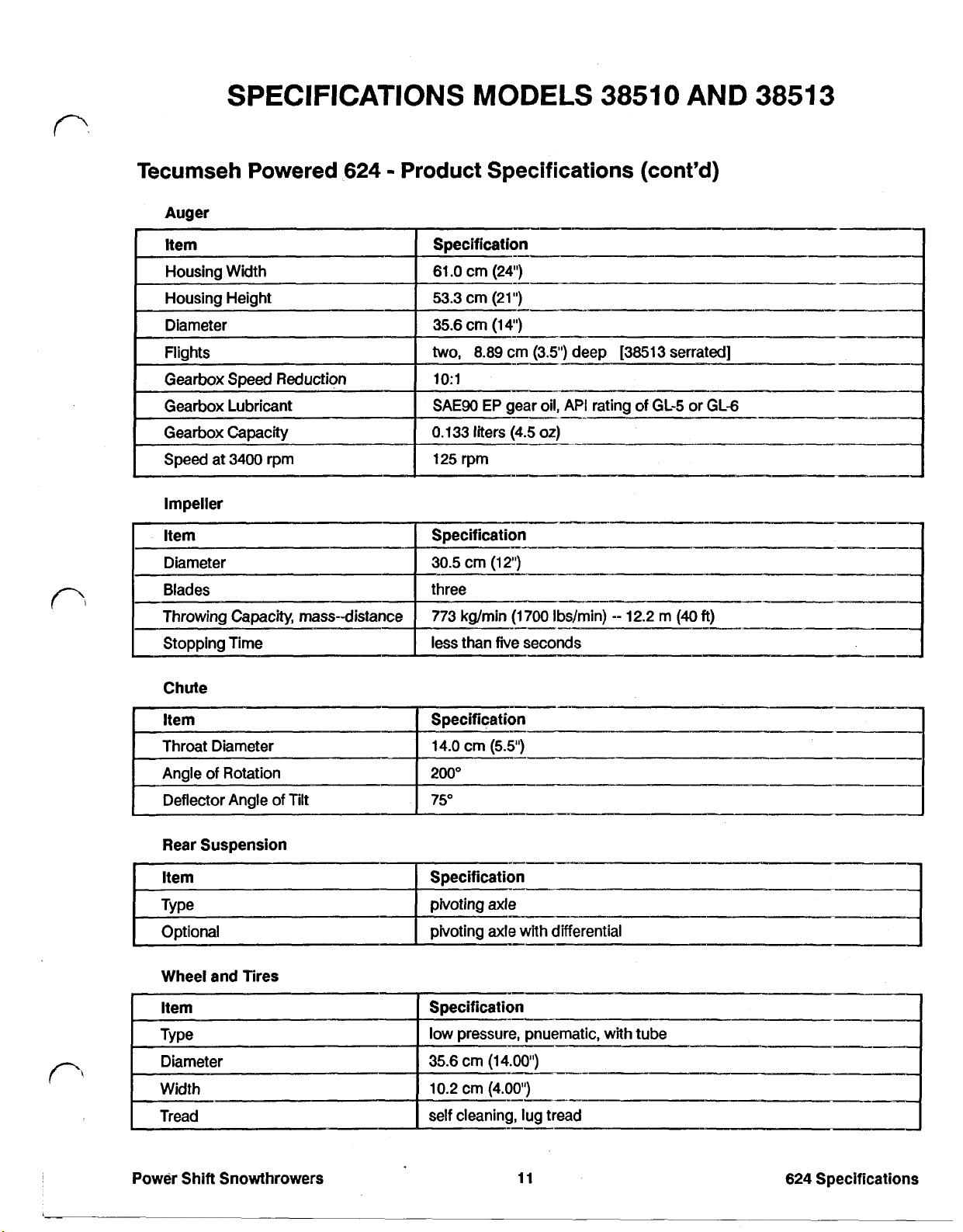
Tecumseh Powered
Auger
Impeller
624
Product Specifications (cont'd)
30.5
cm
(12'”)
Chute
Throat Diameter
Angle
of
Deflector Angle
I
Rear Suspension
Item
Type pivoting axle
Optional
Wheel and Tires
Rotation
of
Tilt
14.0
cm
I
200"
75"
pivoting axle
(5.5”)
with
differential
I
I
Power
Shift
Snowthrowers
11
624
Specifications
Page 19
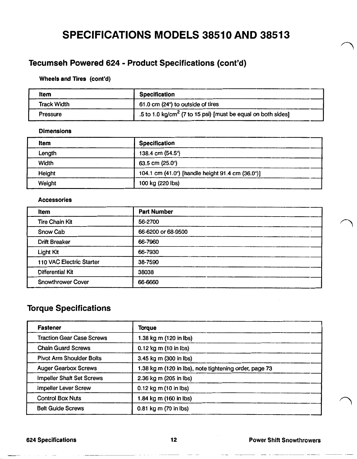
SPECIFICATIONS MODELS 38510 AND 38513
Tecumseh Powered
Wheels and Tires (cont'd)
Track Width
Dimensions
I
Item
Weight
624
Product Specifications (cont'd)
61
.O
cm (24") to outside
.5
to 1
.O
kg/cm2 (7
Specification
138.4 cm (54.5")
63.5
cm (25.0")
104.1 cm (41
100 kg (220 I bs)
.O'”)
[handle height 91.4 cm (36.O'”)
of
tires
to
15 psi) [must be equal on both sides] Pressure
I
I
I
Torque Specifications
Fastener
Traction Gear Case Screws
Chain Guard Screws
Pivot Arm Shoulder Bolts
Auger Gearbox Screws
Impeller Shaft Set Screws
Impeller Lever Screw
Control Box
Belt Guide Screws
624
Specifications
Nuts
Torque
1.38 kg m (120 in Ibs)
0.12 kg
3.45 kg m (300 in Ibs)
1.38 kg m (120 in Ibs), note tightening order, page 73
2.36 kg m (205 in Ibs)
0.12 kg m (10 in Ibs)
1.84 kg m (160 in
0.81 kg m (70 in Ibs)
m
(10 in
12
Ibs)
Ibs)
I---
Power Shift Snowthrowers
Page 20
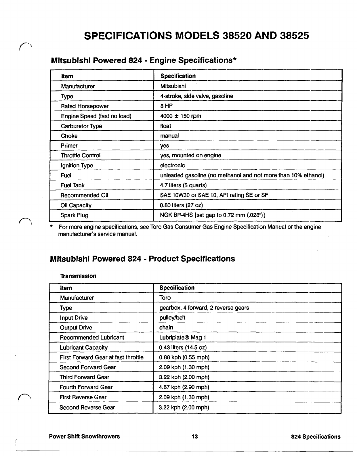
Mitsubishi Powered 824 Engine Specifications*
Item
Manufacturer
Type
Rated Horsepower
Engine Speed (fast no load)
Carburetor Type
Choke
Primer
Throttle Control
Fuel unleaded gasoline (no methanol and not more than 10% ethanol)
Fuel Tank 4.7 liters
Recommended Oil
Oil Capacity
Spark Plug NGK BP-4HS [set gap to 0.72 mm (.028')
*
For more engine specifications, see Toro Gas Consumer Gas Engine Specification Manual or the engine
manufacturer's service manual.
Specification
Mitsubishi
4-stroke, side valve, gasoline
8
HP
4000
float
manual
yes
I
yes, mounted on engine
I
electronic
SAE 10W30 or SAE 10, API rating SE or SF
0.80
150 rpm
liters (27
(5
quarts)
oz)
Mitsubishi Powered 824 Product Specifications
Transmission
Second Forward Gear 2.09 kph (1.30 mph)
Third Forward Gear
Fourth Forward Gear 4.67 kph (2.90 mph)
First Reverse Gear
Second Reverse Gear
3.22 kph (2.00 mph)
2.09 kph (1.30 mph)
3.22 kph
(2.00
mph)
Power Shift Snowthrowers
13
824
Specifications
Page 21
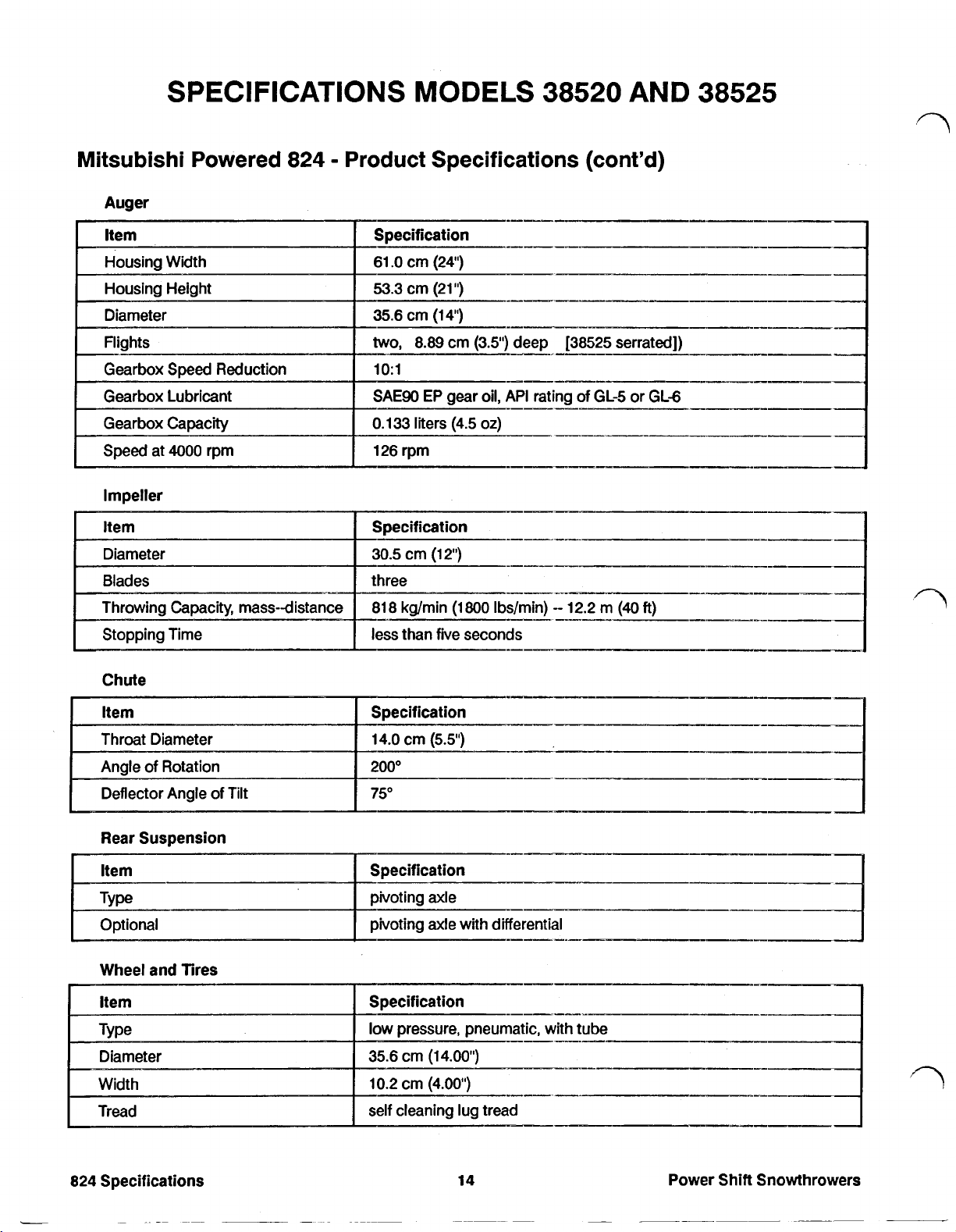
SPECIFICATIONS MODELS 38520 AND 38525
Mitsubishi Powered
Auger
Housing Width
I
ltem
824
Product Specifications (cont'd)
61
.O
cm
(24")
I
[
Stopping Time less than five seconds
Rear Suspension
ltem
Type pivoting axle
Optional pivoting axle with differential
824
Specifications
Power
Shift
Snowthrowers
Page 22
SPECIFICATIONS
MODELS
38520
AND
Mitsubishi Powered 824 Product Specifications (cont'd)
Wheels and Tires (cont'd)
I
Item
Track Width
I
Specification
61.O cm (24") to outside of tires
38525
Pressure
Dimensions
Accessories
.5
to
1.O
56-2700
66-6200
66-7960
66-7950
38038
66-6660
kg/cm2 (7 to 15 psi) [must be equal on both sides]
)
[handle height 91.4 cm (36.0'”)
or 68-9500
Mitsubishi Powered 824 Torque Specifications
in
Ibs),
note tightening order, page 73
Power
Shift Snowthrowers
15
824
Specifications
_I
Page 23
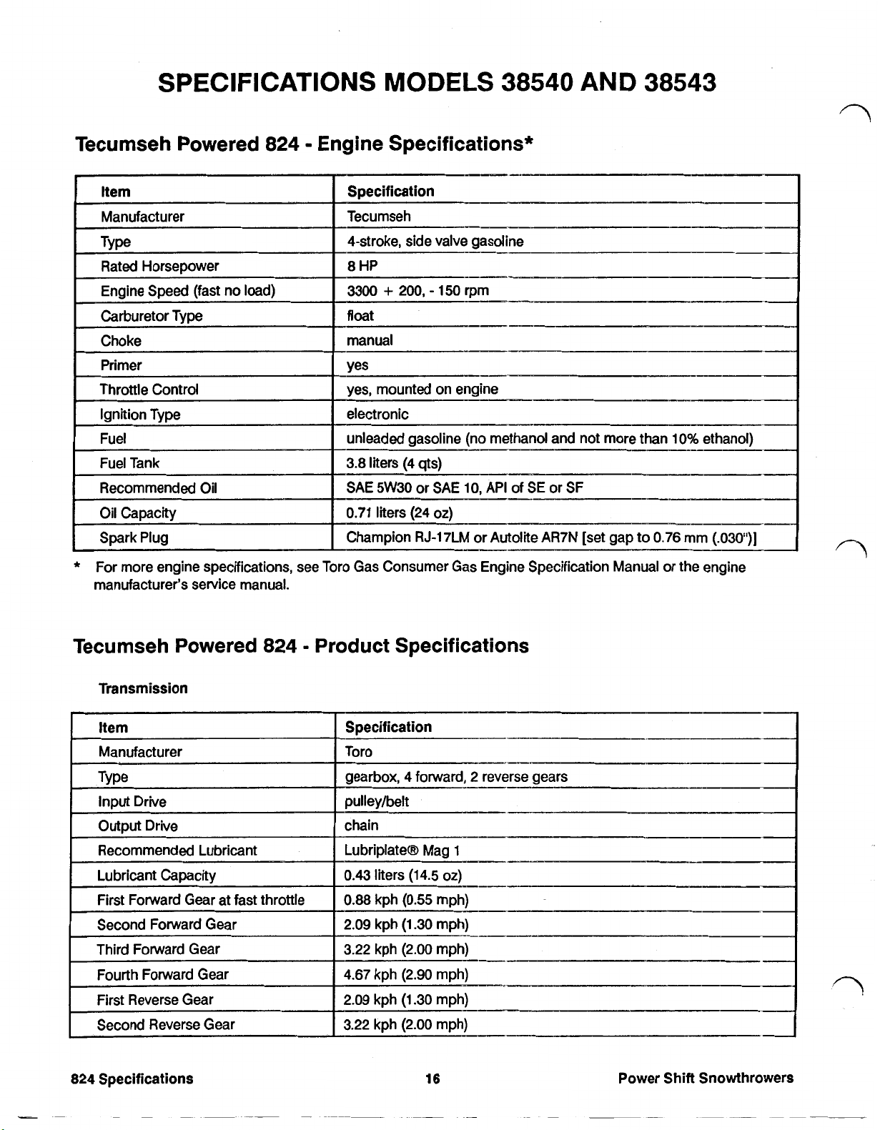
SPECIFICATIONS
MODELS
38540
AND
38543
Tecumseh Powered
824
Engine Specifications*
Specification
Tecumseh
4-stroke, side valve gasoline
8 HP
+
200,
150
3300
float
manual
Yes
yes, mounted on engine
electronic
unleaded gasoline (no methanol and not more than
3.8
liters (4
SAE 5W30
0.71
Champion
liters
qts)
or
(24
RJ-17LM
rpm
_-
SAE 10, API
oz)
or Autolite
of
SE
AR7N
or
SF
[set gap to
I
-_._-I-
I---
_._.___
10%
0.76
ethanol)
mm
(.030'))
*
For more engine specifications, see Toro Gas Consumer Gas Engine Specification Manual
manufacturer's service manual.
Tecumseh Powered
Transmission
824
Product Specifications
or
the engine
824
Specifications
16
Power Shift Snowthrowers
Page 24
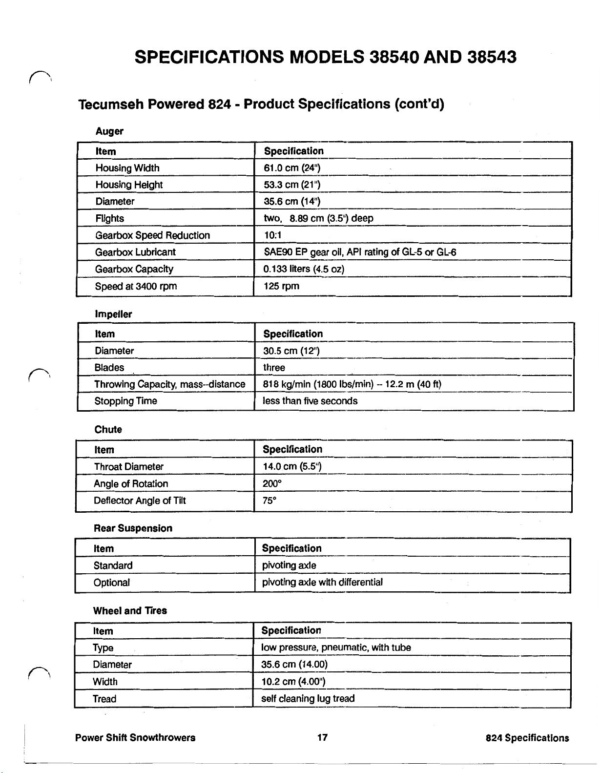
SPECIFICATIONS MODELS 38540 AND 38543
Tecumseh Powered
Auger
Impeller
Item
Diameter
Blades
Throwing Capacity, mass-distance
Stopping Time
824
Product Specifications (cont'd)
Specification
30.5
cm
(12')
three
818 kg/min
less than fie seconds
(1800
Ibs/min)
12.2
m (40
ft)
Chute
Rear Suspension
Wheel and Tires
Specification
14.0 cm
200"
75"
(5.5')
Power Shift Snowthrowers
17
824
Specifications
Page 25
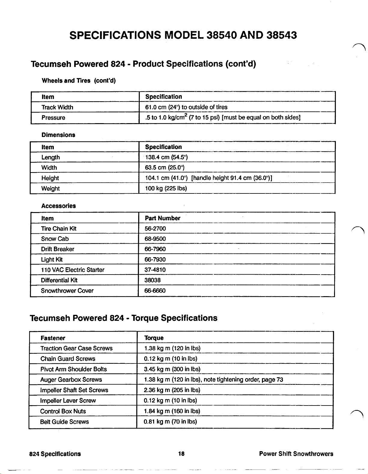
SPECIFICATIONS
MODEL
38540
AND
38543
Tecumseh Powered
Wheels and Tires (cont’d)
Dimensions
824
Product Specifications (cont’d)
15
psi) [must
eight
91.4
be
equal
cm
on
(36.0’)
-~I--
both si
Tecumseh Powered
824
Specifications
824
Torque Specifications
18
Power Shift Snowthrowers
Page 26
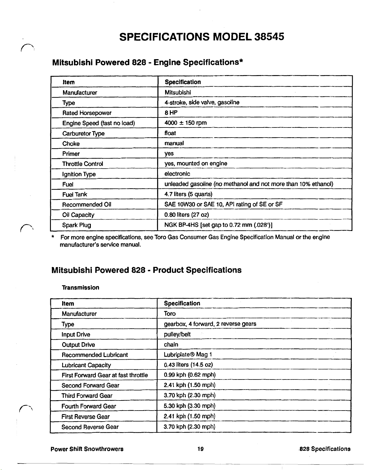
Mitsubishi Powered
828
Engine Specifications*
*
For more engine specifications, see
manufacturer's service manual.
Mitsubishi Powered
Transmission
828
Toro
Gas Consumer Gas Engine Specification Manual or the engine
Product Specifications
Power
Shift
Snowthrowers
19
828
Specifications
Page 27
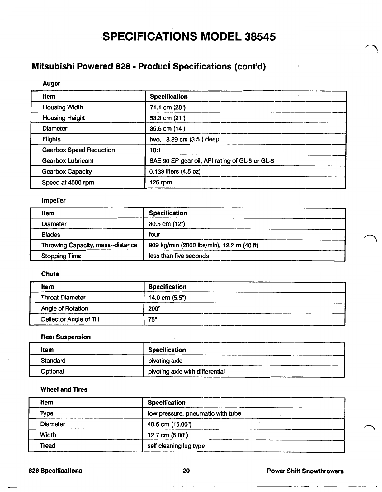
SPECIFICATIONS
MODEL
38545
Mitsubishi Powered
Impeller
Item Specification
Diameter
Blades
Throwing Capacity, mass-distance
Stopping Time
828
Product Specifications (cont'd)
30.5
cm
four
909
kg/min
less than five seconds
(12")
(2000
Ibs/min),
12.2
m
(40
ft)
Chute
Item
Throat Diameter
Angle
of
Rotation
Deflector Angle of Tilt
Rear Suspension
Wheel and Tires
Item
Type low pressure, pneumatic with tube
Diameter
Width
Tread
Specification
14.0
200°
75"
Specification
40.6
12.7
self cleaning lug type
cm
cm
cm
(5.5")
(16.00')
(5.00')
828
Specifications
20
Power Shift Snowthrowers
Page 28
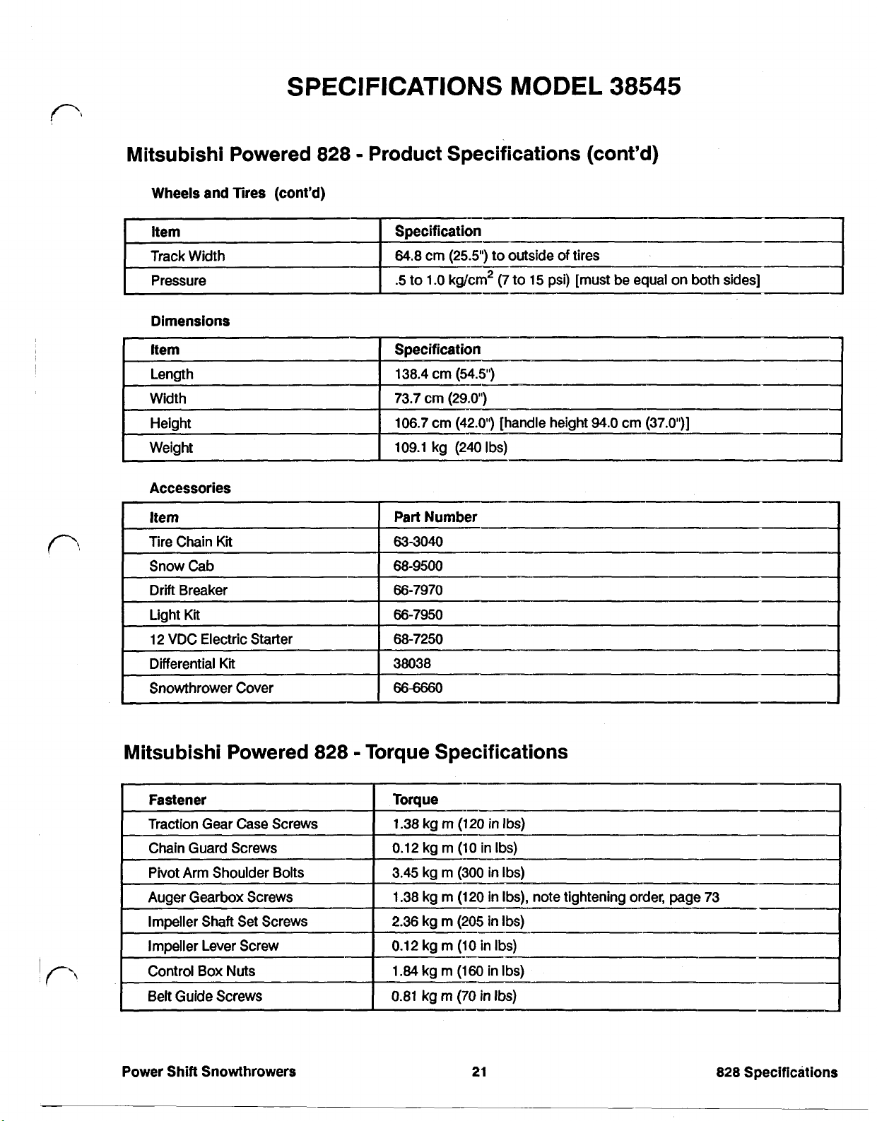
SPECIFICATIONS MODEL
38545
Mitsubishi Powered
Wheels and Tires (cont'd)
I
Item
Track
Width
Pressure
Dimensions
Accessories
828
Product Specifications (cont'd)
64.8
cm
(25.5')
.5
to
1.O
kg/cm2
to outside
(7
to
of
tires
15
psi) [must be equal
on
both sides]
I
I
Mitsubishi Powered
Power Shift Snowthrowers
828
Torque Specifications
21
828
Specifications
Page 29
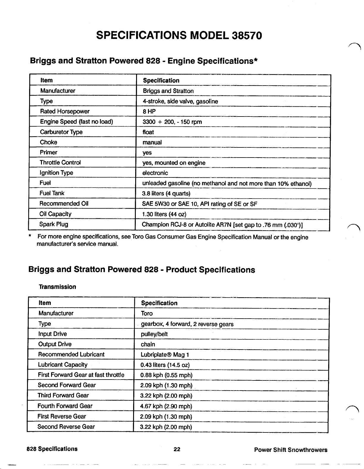
SPECIFICATIONS
MODEL
38570
Briggs and Stratton Powered
Champion RCJ-8 or Autolite AR7N [set gap to
828
Engine Specifications*
_I-
.76
mm
(.030'”)
*
For more engine specifications, see Toro Gas Consumer Gas Engine Specification Manual or the engine
manufacturer's service manual.
Briggs and Stratton Powered
Transmission
828
Product Specifications
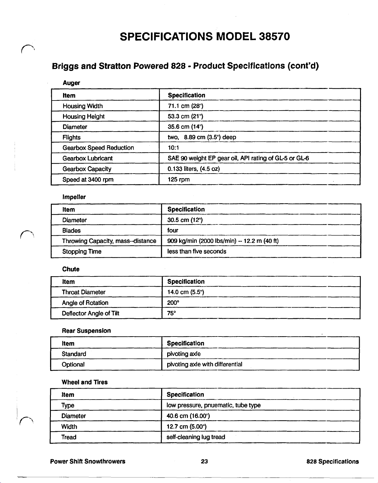
Page 30
SPECIFICATIONS
MODEL
38570
Briggs
Auger
Impeller
and
Stratton
Powered
828
Product Specifications (cont'd)
i
r'
Chute
Wheel and
Tires
self-cleaning lug
tread
Power
Shift Snowthrowers
23
828
Specifications
Page 31
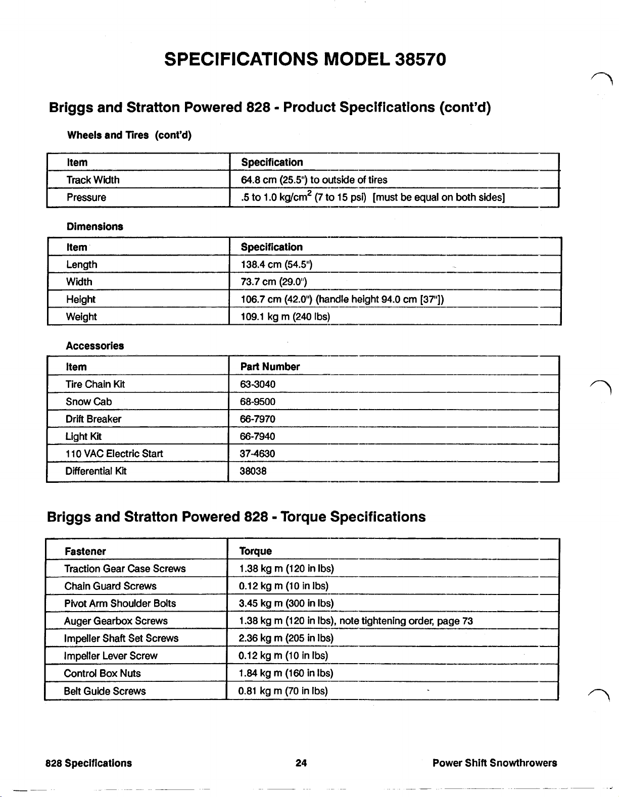
SPECIFICATIONS
MODEL
38570
Briggs and Stratton Powered 828 Product Specifications (cont'd)
Wheels and Tires (cont'd)
Specification
Track Width 64.8 cm (25.5) to outside
.5 to
1.O
Pressure
Dimensions
Item
Length
Width
Height
Weight
Specification
138.4 cm
73.7 cm
106.7 cm (42.0') (handle height 94.0 crn [37"])
109.1
kg/cm2 (7 to
(54.5")
(29.0")
kg m (240 Ibs)
of
tires
15
psi) [must be equal
on
both sides]
Briggs and Stratton Powered 828 Torque Specifications
Power
Shift
Snowthrowers
Page 32

SPECIFICATIONS
MODEL
Tecumseh Powered 828 Engine Specifications*
38573
Item
Manufacturer
Ignition Type electronic
Fuel Tank
oil
Capacity
Spark Plug Champion
*
For more engine specifications, see Toro Gas Consumer Gas Engine Specification Manual or the engine
manufacturer's service manual.
Specification
Tecumseh
yes, mounted on engine
unleaded gasoline (no methanol and not more than
3.8
liters
(4
quarts)
SAE
5W30
or
SAE10, API
RJ-17LM
or
Autolite
rating
of
SE
AR7N
or SF
[set gap to
0.76
10%
ethanol)
mm
(.030'”)
Tecumseh Powered 828 Product Specifications
Transmission
Specification
Toro
4
Manufacturer
gearbox,
pulley/belt
chain
Lubriplate(R) Mag
0.43
0.88
2.09
3.22
4.67
2.09
3.22
forward, 2 reverse gears
1
liters
(14.5 oz)
kph
(0.55
mph)
kph
(1.30
mph)
kph
(2.00
mph)
kph
(2.90
mph)
kph
(1.30
mph)
kph
(2.00
mph)
Power
Shift
Snowthrowers
25
828
Specifications
Page 33

Tecumseh Powered
Impeller
828
Product Specifications (cont'd)
Specification
30.5
cm
(12")
four
909
kg/min
less than five seconds
(2000
lbs/min)
12.2
rn
(40
ft)
Rear Suspension
Item
Optional pivoting axle
Wheel
I
Item
I
Type
Diameter
Tread
828
Specifications
and
Tires
Specification
low
pressure, pnuematic, tube type
40.6
cm
(16.00")
with
differential
Power
Shift
Snowthrowers
I
I
Page 34
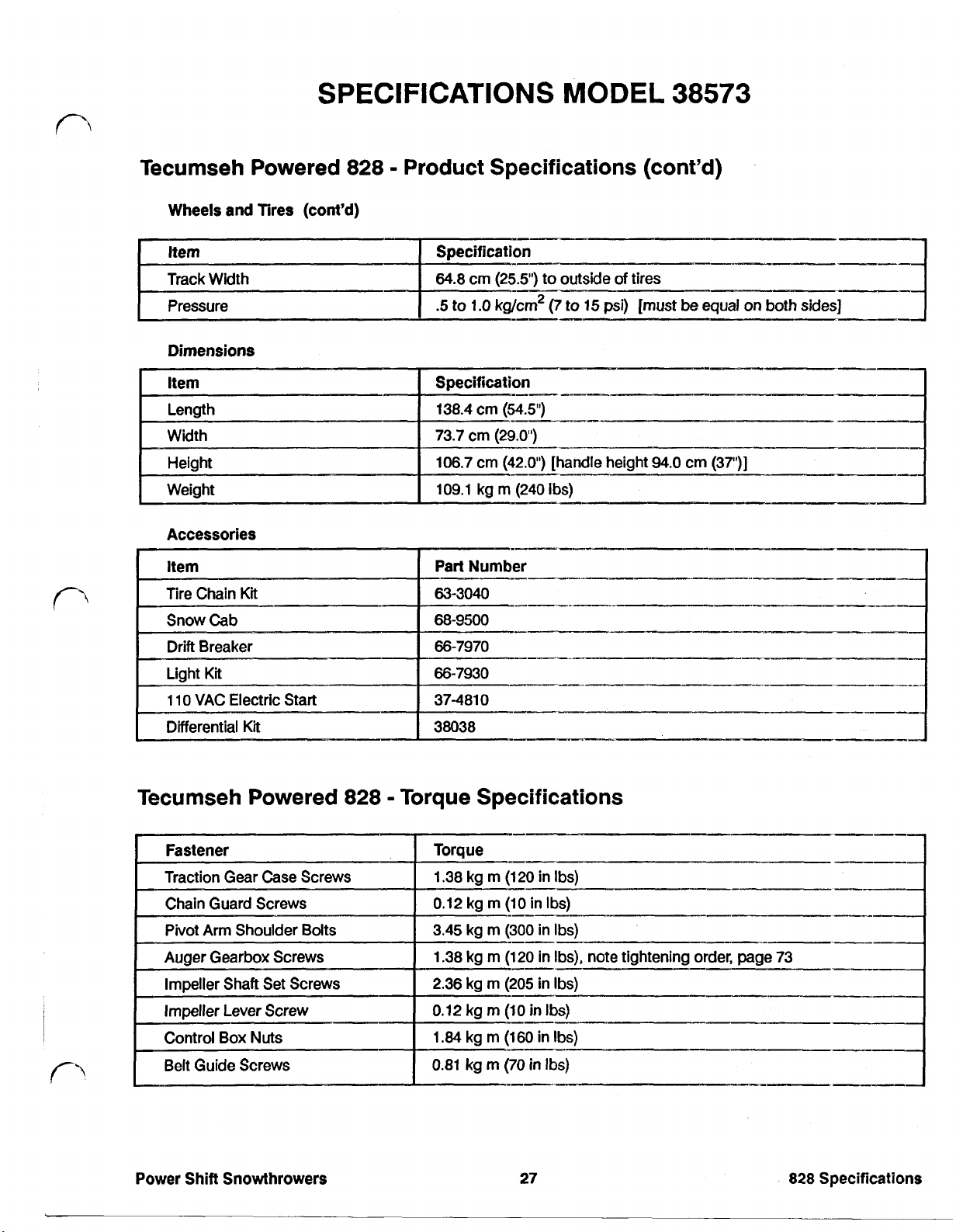
SPECIFICATIONS MODEL
38573
Tecumseh Powered 828 Product Specifications (cont'd)
Wheels and Tires (cont'd)
I
Item
Pressure
Dimensions
Width
Height
Weight
Accessories
Specification
64.8
crn
(25.5") to outside
.5
to
1.0
kg/cm2
cm
73.7
106.7
109.1
(29.0")
crn
(42.0') [handle height
kg m (240 Ibs)
(7 to
15
of
psi)
tires
[must
94.0
be
cm
equal on both
(37")]
I
sides]
I
Tecumseh Powered 828 Torque Specifications
Torque
1.38 kg
0.12
3.45
1.38
2.36
0.12 kg
1.84
0.81
Power Shift Snowthrowers
m
(120
in Ibs)
kg
rn
(10
in
Ibs)
kg
m
(300 in Ibs)
kg m
(120
in Ibs), note tightening order, page 73
kg
m (205 in
m
(10
kg
m
(160
kg m (70 in Ibs)
in Ibs)
-_I__.
in
27
Ibs)
Ibs)
I_.--
--__-
828
Specifications
Page 35

SPECIFICATIONS
MODELS
38565 AND 38580
Briggs and Stratton Powered 1132 Engine Specifications*
no methanol and not more
_.-
*
For more engine specifications, see Toro Gas Consumer Gas Engine Specification Manual or the engine
manufacturer’s service manual.
Briggs and Stratton Powered 1132 Product Specifications
1132
Specifications
28
Power Shift Snowthrowers
Page 36
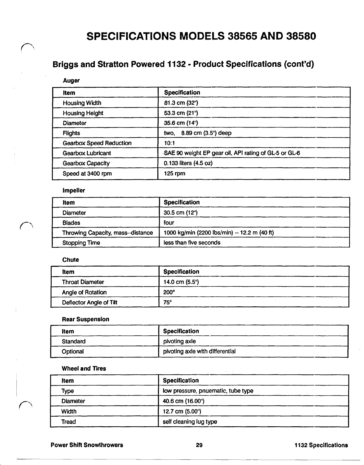
Briggs and Stratton Powered
Auger
Impeller
1132
Product Specifications (cont'd)
Chute
Rear Suspension
Wheel and Tires
Item
Type
Diameter
Width
Tread
Specification
low
pressure, pneumatic tube type
40.6
cm
(16.00'1
12.7 cm
self cleaning lug type
(5.00')
I
I
Power Shift Snowthrowers
29
1132
Specifications
Page 37

SPECIFICATIONS MODELS 38565 AND 38580
Briggs and Stratton Powered
Wheels and Tires (cont'd)
Track Width
Pressure
64.8
.5
1132
cm
to
1.O
Product Specifications (cont'd)
(25.5")
kg/cm2
to outside
(7
to
of
tires
15
psi) [must be equal on both sides]
Torque Specifications
1132
Specifications
30
Power Shift Snowthrowers
Page 38

SPECIAL TOOLS AND OTHER NECESSITIES
The Power Shift Snowthrowers do not require any
complex tools for most servicing. Servicing can be
accomplished with the following:
Necessary
Complete English Socket Wrench Set (1/4" thru 1")
Complete English End Wrench Set (1/4" through 1")
Phillips Screwdrivers
Standard Screwdrivers
Pocket Knife
Rubber Mallot
Pliers (regular, needle nose and linesman)
Snap Ring Pliers (outside)
Tools
it
is a
In addition to those tools,
following
Lubricants, Sealants and Adhesives
on
hand:
good
idea to have the
Power Shift Snowthrowers
31
Special Tools
Page 39

TROUBLESHOOTING
Unit Does Not Propel Forward
Remedy
Check tire pressure, lock differential, install chains
Position klik Pin through wheel and
Adjust cable
Adjust traction cable
Remove ice accumulation in lower belt cover.
Repair gear or jaw damage
Unit will not Propel Backward
Possible Causes
Wheels not pinned to axle
Reverse cable too loose
Traction belt slipping
Reverse bevel gear or jaw
clutch malfunction
Remedy
Position klik pin through wheel and axle
Adjust reverse cable
Adjust traction cable
Repair reverse gear or jaw clutch damage
axle
I
Neutral Not in Correct Location
I I
Possible Causes Remedy
Lower shift rod not adjusted correctly
Shift bracket incorrectly assembled Reassemble control box correctly
Adjust lower shift rod
I
Shift Lever Will Not Lock in Power Shift or Reverse
Possible Causes Remedy
Lockout lever
Lockout lever binding
Lockout lever spring malfunction
tabs
broken Replace lockout lever
Free by spraying with WD40
Replace lock out lever spring
Power
Shift
Snowthrowers
I
I
Page 40
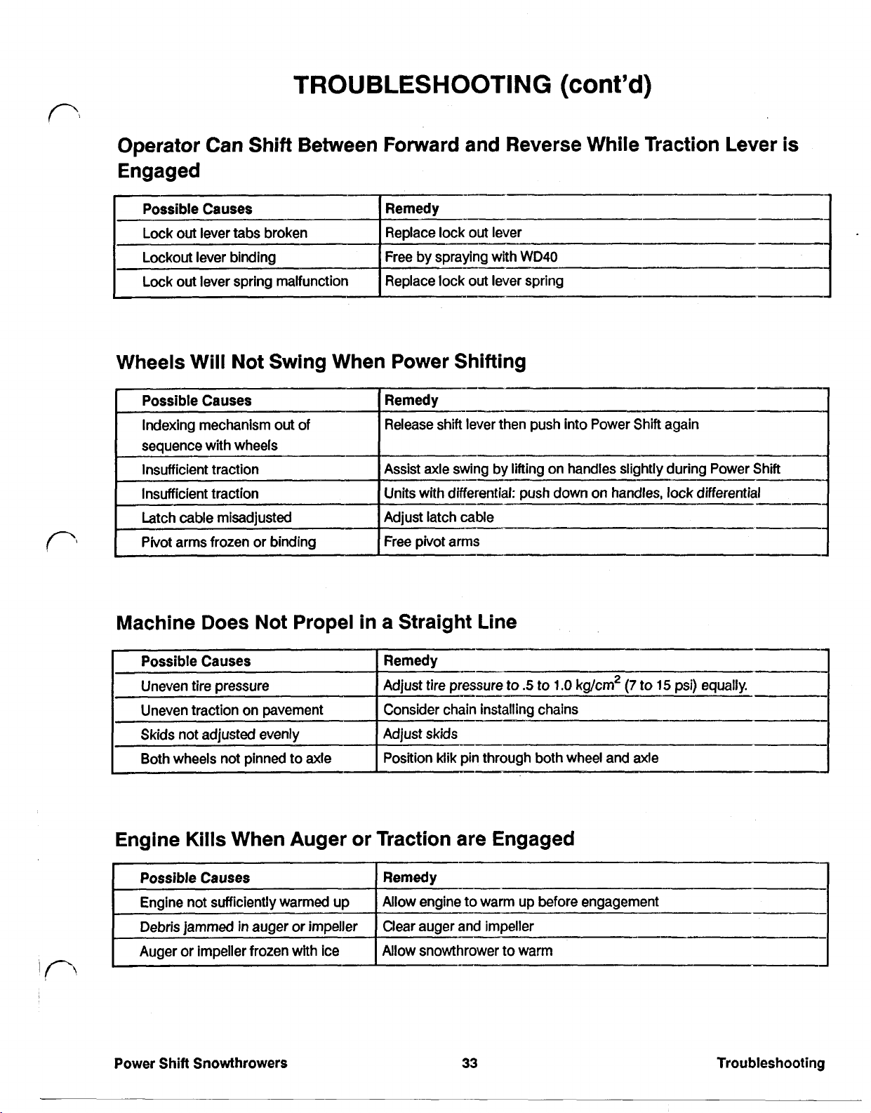
TROUBLESHOOTING
(cont'd)
Operator Can Shift Between Forward and Reverse While Traction Lever is
Engaged
Possible Causes
Lock out lever tabs broken
Lockout lever binding
Lock out lever spring malfunction Replace lock out lever spring
Remedy
Replace lock out lever
Free by spraying with WD40
I
Wheels Will Not Swing When Power Shifting
Possible Causes
Indexing mechanism out
sequence with wheels
Insufficient traction
of
Remedy
Release shift lever then
Assist axle swing by lifting on handles slightly during Power Shift
Units with differential: push down on handles, lock differential
Adjust latch cable
Free pivot arms
push
into Power Shift again
I
Machine Does Not Propel in a Straight Line
I
Possible Causes Remedy
Uneven tire pressure
Uneven traction on pavement
Skids not adjusted evenly
Both wheels not pinned to axle Position klik pin through both wheel and axle
Adjust tire pressure to
Consider chain installing chains
Adjust
skids
.5
to
.O
1.0
kg/cm2
Engine Kills When Auger or Traction are Engaged
Possible Causes
Engine not sufficiently warmed up
Debris jammed
Auger or impeller frozen with ice
in
auger or impeller
Remedy
Allow engine to warm
Clear auger and impeller
Allow snowthrower to warm
up
before engagement
(7
to
15
psi) equally.
-I
I
Power Shift Snowthrowers
33
Troubleshooting
Page 41

TROUBLESHOOTING
Poor Snowthrowing Performance
Impeller or Auger Does Not Turn
Remedy
Clear debris
Allow snowthrower to warm
Adjust impeller belt
(cont'd)
Gear malfunction
in
auger gearbox
Traction or Impeller Does
-Possible Causes
Cable too tight
Belt guide broken
Incorrect belt
Chute Plugs With Snow
Possible Causes
Engine rpm too slow
Belt slippage
Tighten pulley fasteners
Replace auger bolt
Tighten impeller shaft fasteners
Repair auger gearbox
Not
Disengage
Replace belt guide
Check parts catalog for correct belt
Always throw snow at full throttle
Adjust impeller belt
Ground speed not matched
Snow too wet
Troubleshooting
in
Select slower gear in heavy conditions, faster gear
Sand, paint and wax chute and rough areas in housing and chute
Allow snow to melt or freeze
34
Power Shift Snowthrowers
light conditions
Page 42
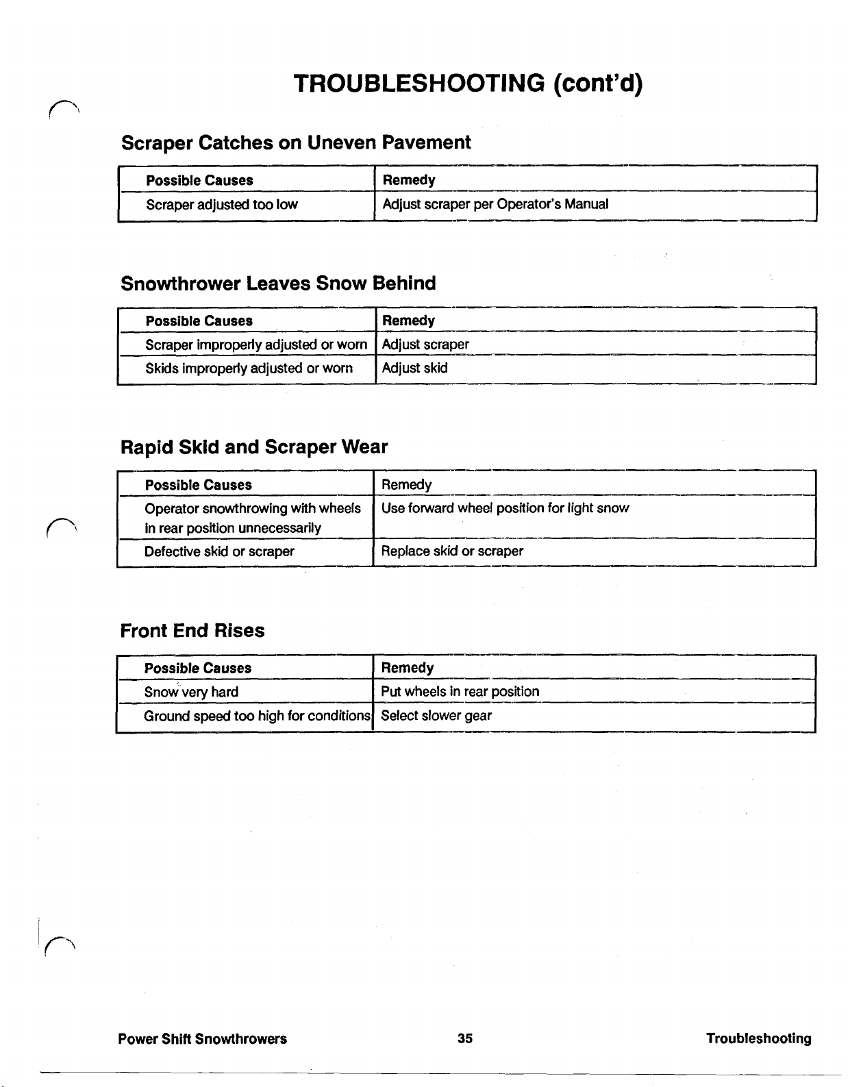
TROUBLESHOOTING
Scraper Catches on Uneven Pavement
Snowthrower Leaves Snow Behind
Remedy
(cont’d)
per Operator’s Manual
Scraper improperly adjusted or worn
Skids improperly adjusted or worn
Adjust scraper
Adjust skid
Rapid Skid and Scraper Wear
Possible Causes
Operator snowthrowing with wheels
in rear position unnecessarily
Defective or scraper
Remedy
Use forward wheel position
Replace skid or scraper
Front End Rises
___-
for
light snow
Power
Shift
Snowthrowers
35
Troubleshooting
Page 43
CAUTION: To prevent accidental starting of the engine
while performing maintenance, rotate the ignition key to
off
and remove
it
from the switch. Next, pull the wire
off
the spark plug and make sure the wire does not
accidentally touch the plug.
Maintenance Draining Gasoline
Stop the engine and pull the wire
1.
2.
Remove the cap from the fuel tank and use a
off
spark plug.
pump-type syphon to drain fuel into clean gas can.
NOTE: This is the only procedure recommended
for draining
fuel.
CAUTION: Since gasoline is highly flammable,
it
drain
outdoors and make sure the engine is cool
to prevent a potential fire hazard. Wipe up any
gasoline that may have spilled.
Do
not drain
gasoline near any open flame or where the
gasoline fumes may be ignited by a spark.
Do
not
smoke a cigar, cigarette or a pipe when handling
gasoline.
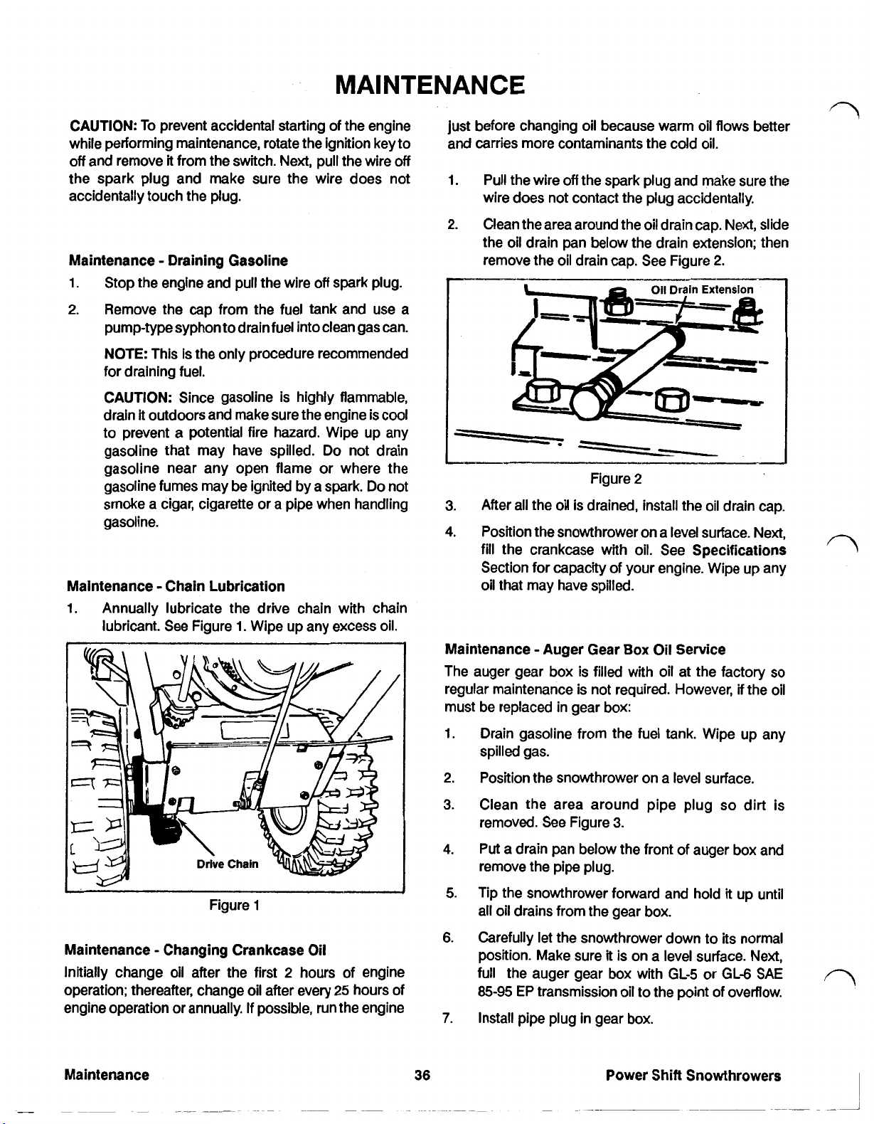
Maintenance Chain Lubrication
1.
Annually lubricate the drive chain with chain
lubricant. See Figure
1.
Wipe up any excess oil.
just before changing oil because warm oil flows better
and carries more contaminants the cold oil.
1.
Pull the wire
off
the spark plug and make sure the
wire does not contact the plug accidentally.
2.
Clean the area around the oil drain cap. Next, slide
the oil drain pan below the drain extension; then
remove the oil drain cap.
3.
After all the oil is drained, install the oil drain cap.
4.
Position the snowthrower on a level surface. Next,
fill
the crankcase with oil. See Specifications
Section for capacity
See
Figure
Oil
Drain
of
your engine. Wipe up any
2.
Extension
oil that may have spilled.
Box
Maintenance Auger Gear
The auger gear box is filled with oil at the factory
regular maintenance is not required. However,
Oil Service
if
the oil
so
must be replaced in gear box:
Figure
1
Maintenance Changing Crankcase Oil
2
Initially change oil after the first
operation; thereafter, change oil after every
hours of engine
25
hours of
engine operation or annually. If possible, run the engine
1.
Drain gasoline from the fuel tank. Wipe up any
spilled gas.
2.
Position the snowthrower on a level surface.
3.
Clean the area around pipe plug
removed. See Figure
4.
Put a drain pan below the front of auger box and
3.
remove the pipe plug.
Tip the snowthrower forward and hold
5.
all oil drains from the gear box.
Carefully let the snowthrower down to its normal
6.
position. Make sure it is on a level surface. Next,
full the auger gear box with
85-95
EP
transmission oil to the point
7.
Install pipe plug in gear box.
GL-5
or
Power Shift Snowthrowers
so
it
up until
GL-6
of
overflow.
dirt is
SAE
Page 44

Maintenance Auger Gear Box Oil Service (cont'd)
Figure
3
Maintenance Impeller Drive Belt Adjustment
If
the auger/impeller
belt
slips resulting in decreased
snowthrowing performance, an adjustment is required.
WHENEVER
ADJUSTMENT
1.
Remove the three flanged head capscrews
A
NEW BELT
IS
REQUIRED.
IS
INSTALLED, AN
securing the belt cover to engine frame and slide
belt cover up the cables.
2.
Check idler and brake adjustment. There should
be
a minimum clearance of 3 mm
(1/8”)
between
the tab on the impeller idler arm and the brake
arm. See Figure
clearance, the
4.
If there is less than 3 mm
belt
must be replaced.
(1/8'”)
Rotate the bottom jam nut upward to increase belt
4.
tension.
NOTE: When adjusting the cable, always rotate
the nut one turn at a time.
belt
NOTE: Do not adjust the
too tight because
may cause the auger/impeller to turn when the
auger/impeller is in
the
disengaged position.
occurs, readjust the lever by loosening belt
tension.
Tighten upper jam nut against bracket.
5.
CAUTION: Improper adjustment may cause
injury if auger/impeller turns when the lever
disengages. Use only genuine Toro replacement
parts.
Recheck the idler and brake adjustment referring
6.
to step
Reinstall the belt cover.
7.
Check tension of belt by operating the auger.
8.
2.
belt slips, repeat procedure.
If
this
If
the
it
Figure
3.
Loosen the upper jam nut securing the auger/
4
impeller cable to the mounting bracket. See
Figure
5.
Power Shift Snowthrowers
Maintenance Traction Drive Belt Adjustment
If
the traction belt slips during operation, an adjustment
is
required. Whenever the belt is replaced, an
adjustment is required.
1.
Loosen the upper jam nut securing the traction
cable to the mounting bracket.
2.
Rotate the bottom jam nut upward to increase belt
tension.
37
Maintenance
Page 45

Maintenance Traction Drive Belt Adjustment
(cont'd)
NOTE:
When adjusting cable, always rotate nut
one turn at a time.
3.
Tighten the upper jam nut against the bracket.
4.
Check the tension of the belt by operating the
machine. If the belt slips, repeat the procedure.
CAUTION: Do not adjust the belt too tight
because
it
may cause the snowthrower to creep
when traction lever is in the disengaged position.
If
this occurs, readjust by loosening belt tension.
Maintenance Replacing Drive Belts
If
the auger/impeller belt or traction belt become worn,
glazed, stretched, oil-soaked, or otherwise defective,
belt replacement is required.
1.
Pull wire
off
the spark plug and make sure
it
does
not contact the plug accidentally.
2.
Remove the three thread forming screws holding
the belt cover in place, and slide the belt cover up
cables.
7.
If
replacing the traction belt, slide the mid section
of the on pulley and belt
off
crankshaft and remove
belt from transmission pulley.
8.
On the control cable which corresponds to the
belt being replaced, loosen the jam nuts securing
cable to bracket. Cable must
be
free to slide in the
bracket when changing the belt(s).
9.
Reinstall the belts by reversing procedure. Make
sure tabs
in
half sheave are inserted into the
mounting grooves in the auger/impeller pulley
when reinstalling.
NOTE:
Make sure the idler pulleys are aligned
with the belts when reinstalling idler pulley
assembly.
10.
Readjust the belts, referring to Maintenance
Impeller Drive Belt Adjustment or Maintenance
Traction Drive Belt Adjustment, pages
38.
CAUTION: Improper adjustment may cause
injury
if
auger/impeller turns when the lever
disengages. Use only genuine Toro replacement
parts.
37
and
3.
Move the speed shift control to
4.
Remove the two flanged head capscrews
N,
neutral.
securing the idler pulley assembly to the engine
frame. Remove the idler pulley assembly. See
Figure
5.
Remove the capscrew and lockwasher securing
6.
Figure
6
the half sheave to front of pulley assembly.
Maintenance Drive Chain Adjustment
The drive chain must be adjusted to maintain
1/8-3/8
of
an inch deflection at mid span between transmission
and axle sprocket. Check chain deflection after every
25
hours of operation.
1.
Check deflection of the chain by lifting up on the
chain with moderate pressure at mid span. There
should be
1/8-3/8”
specified an adjustment is required.
deflection.
If
deflection is not as
See
Figure
Deflection
3/8”
7.
6.
Slide auger/impeller half sheave and belt
crankshaft and remove belt from impeller pulley.
Maintenance
off
38
Figure
7
Power Shift Snowthrowers
I
Page 46

Maintenance Drive Chain Adjustment (cont'd)
NOTE:
To
adjust the drive chain,
the
snowthrower
must be tipped up on the auger housing. However,
before the snowthrower is tipped, siphon all
gasoline from fuel tank.
2.
Make sure the wheels are positioned in rear
position. Move the shift control into
2nd
gear and
tip the snowthrower up onto auger housing.
3.
Loosen the four flanged head capscrews (two
each side) securing transmission frame to engine
frame. See Figure
4.
Lightly
9
mm
lift
up on the transmission frame until 3 to
(1/8
to 3/8”) chain deflection is attained, then
8.
retighten the flanged head capscrews.
Figure
NOTE:
lifting
Do not pry or use excessive force when
the transmission frame, as transmission
8
damage may occur.
NOTE:
If
gear shift lever
is
not aligned with the
Power Shift slot in control panel (see Figure
inset), shift rod length must beadjusted as follows:
a. Disconnect the
move
the
jam
b. Rotate the
ball
joint from bellcrank and
nut
up shift rod. See Figure
ball
joint up or down until the gear
shift lever is aligned with the Power Shift slot.
c. Reinstall
the
ball
joint to the bellcrank and
tighten the jam nut.
5.
Recheck the chain deflection and lower the
snowthrower to
its
normal position.
9.
9
Figure
9
Maintenance Spark Plug Service
Check the Specifications Section for the proper spark
plug and gap. Since the air gap between the center and
side electrodes of the spark plug increases gradually
during normal engine operation, install a new plug after
25
hours of engine operation.
1.
Clean the area around the spark plug
so
foreign
matter cannot fall into cylinder when plug is
removed.
2.
Pull the wire
off
the spark plug and remove the
plug from cylinder head.
NOTE:
A
cracked, fouled, or dirty spark plug must
be replaced. Do not sand blast, scrape or clean
the electrodes because grit may eventually
release from the plug and fall into the cylinder. The
result will likely be engine damage.
3.
Set air gap between electrodes of new spark plug.
See Figure
cylinder head. Torque plug to
wrench
10.
Next, install the spark plug in the
15
is
not used, tighten plug firmly.
ft-lb. If torque
Power Shift Snowthrowers
39
Maintenance
Page 47

Maintenance Spark Plug Service (cont’d)
2.
Start the engine and let
it
run until
it
stops because
there is no gasoline in the fuel system.
Remove the spark plug from the cylinder head.
3.
Next, pour
two
teaspoons of engine oil into spark
plug hole in cylinder head. Install the spark plug
in the cylinder head,
but
do not install the wire on
the plug. Then pull recoil starter slowly to
distribute the oil on the inside of the cylinder.
Lubricate the snowthrower: refer to Maintenance
4.
Chain Lubrication, page
36.
Change crankcase
oil: see Operator’s Manual.
Clean the snowthrower. Touch up chipped
5.
surfaces with paint. Sand the affected areas
before painting. Use a rust preventative to prevent
metal parts from rusting.
Figure
4.
Push the wire onto the spark plug.
10
Preparing Snowthrower For Storage
1.
Siphon or remove the gasoline from the fuel tank,
referring to Maintenance Draining Gasoline,
page
36.
Wipe up any gasoline that may have
spilled.
Tighten all screws and nuts.
6.
If
any parts are
damaged, repair or replace them.
7.
Store the snowthrower in
cover
it
to give protection.
The snowthrower may be stored tipped up on the
8.
a
clean, dry place and
auger housing. Make sure to drain gas before
tipping snowthrower.
Page 48
SECTION
1
POWER SHIFT CONTROLS
CAUTION:
require working with some of- the moving
prevent accidental starting of
performing service, take the following precautions:
Rotate the ignition key to
Pull the wire
Make sure the wire does not accidentally touch
the spark plug.
CAUTION:
feature of being able to
for service and storage. Always drain the fuel from the
tank prior to such service taking the following
precautions:
Drain
Wipe up any gasoline that may have spilled.
Do
spark.
Do
Servicing the Power Shift Snowthrower will this motion down to a bellcrank that moves the linkage
parts.
To
the
engine while
off
and remove.
off
the spark plug.
The Power Shift Snowthrower has the
be
stood on the front housing
it
outdoors and make sure the engine
not drain the gasoline near any open flame or
not smoke when handling gasoline.
is
cool.
on top of the transmission.
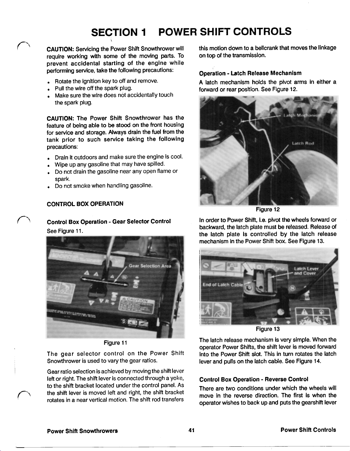
Operation Latch Release Mechanism
A
latch mechanism holds
forward or rear position. See Figure
the
pivot arms
12.
in
either a
Power Shift Snowthrowers
41
Power Shift Controls
Page 49
Control
Box
Operation Reverse Control (cont'd)
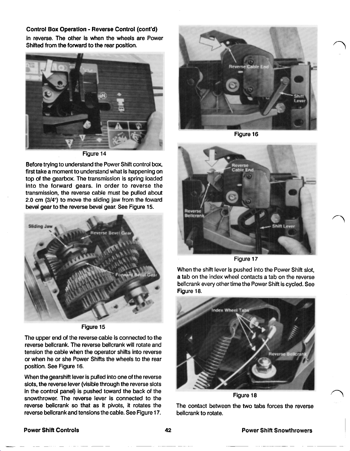
in reverse. The other is when the wheels are Power
Shifted from the forward to the rear position.
Figure
14
Before trying to understand the Power Shift control box,
first take a moment to understand what is happening on
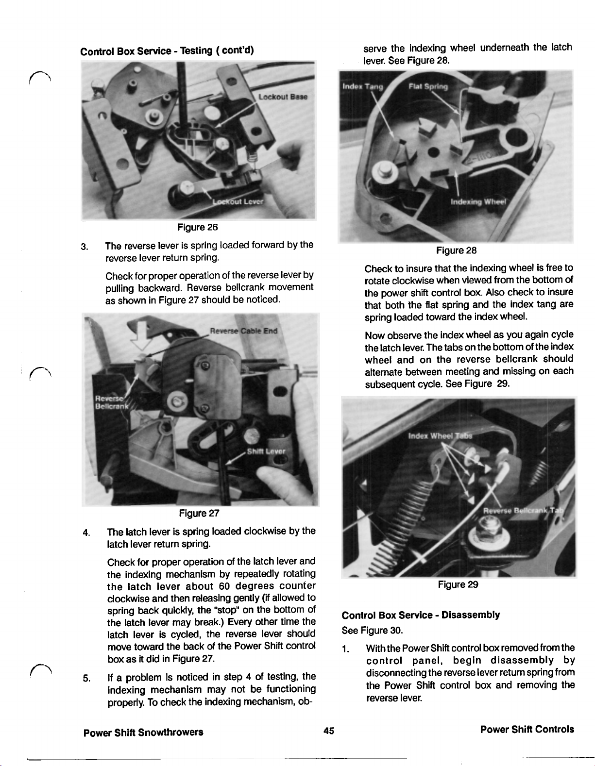
top of the gearbox. The transmission is spring loaded
into the forward gears.
In
order to reverse the
transmission, the reverse cable must be pulled about
2.0
cm
(3/4”)
to move the sliding jaw from the forward
bevel gear to the reverse bevel gear. See Figure
15.
Figure
Figure
16
17
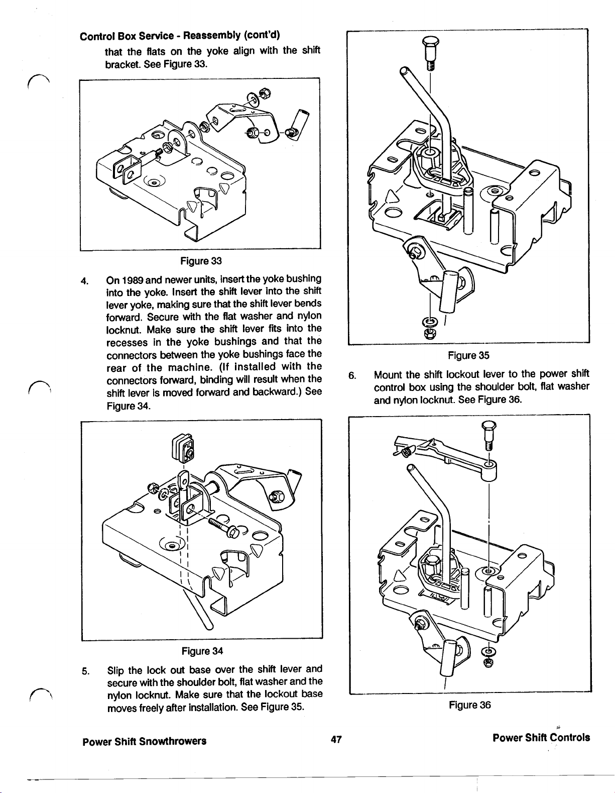
When the shift lever is pushed into the Power Shift slot,
a tab on the index wheel contacts a tab on the reverse
bellcrank every other time the Power Shift is cycied. See
Figure
18.
Figure
15
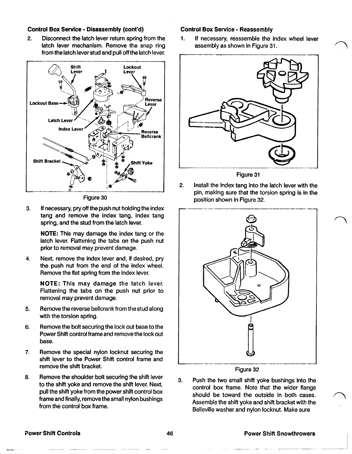
The upper end of the reverse cable is connected to the
reverse bellcrank. The reverse bellcrank will rotate and
tension the cable when the operator shifts into reverse
or when he or she Power Shifts the wheels to the rear
position. See Figure
When the gearshift lever is pulled into one
16.
of
the reverse
slots, the reverse lever (visible through the reverse slots
in the control panel) is pushed toward the back of the
snowthrower. The reverse lever is connected to the
reverse bellcrank
reverse bellcrank and tensions the cable. See Figure
Power
Shift
so
Controls
that as
it
pivots,
it
rotates the
17.
42
Figure
The contact between the
bellcrank
to
rotate.
18
two
tabs forces the reverse
Power Shift Snowthrowers
1
Page 50

Control
The
index
Box
Operation Reverse Control (cont'd)
wheel
is
necessary because
the
wheels must
alternate between forward backward movement
when Power Shifting. bellcrank and the wheels power forward when the
the
When Power Shifting
wheels forward, the indexing
mechanism does nothing but index. The tabs On the
bottom
traction lever is engaged.
Of
the index wheel miss the tab On the reverse
See
Figure
20.
Control
Transmission damage could result
Box
Operation Shift
Lockout
if
the operator were
to shift the transmission into reverse while the unit were
moving forward and vice versa. To prevent this, a shift
lockout is used. This lockout physically prevents the
operator from switching directions without first stopping
the unit.
The lockout base pivots on a shoulder bolt and rotates
whenever the shift lever is moved to either the Power
Shift or reverse slots. See Figure Note however, that 19.
the lockout base does not rotate when the gearshift lever
is
moved from side to side.
When the wheels are to be moved to the rear position,
a
corresponding tab on the reverse bellcrank and the
wheels power backward when the traction lever
engaged. See Figure 21.
Figure 20
tab on the bottom of the index wheel contacts a
is
Figure 19
When
engaged, the
the
traction lever on the left handle
lockout
base
is
free
to
move in either
is
not
direction. However, once the traction lever is engaged,
the
two
tabs on the lockout lever engage the lockout
base. This prevents the shift lever from being moved
forward or backward.
An added benefit
of
the shift lockout is that
it
allows the
operator to lock the gearshift lever in either the Power
Shift or reverse slots by depressing the traction lever.
This allows the operator one hand operation
of
Power
Shift or reverse leaving the other hand free to rotate the
chute.
Control
An indexing mechanism is used
of wheel movement while Power Shifting. This
Box
Operation Indexing Mechanism
to
control the direction
is
necessary because the wheels need to alternate
between forward and reverse when the Power Shift
is
cycled.
Figure
21
The index tang and a flat spring control the rotation of
the index wheel. When the shift lever is pushed into the
Power Shift slot, the index tang rotates the index wheel
1/8
revolution and then prevents the wheel from rotating
backwards when the tabs on the index wheel and
reverse bellcrank make contact. See Figure
As
the shift lever returns to its "at rest" position,
22.
the
index
wheel has a natural tendency to turn backwards due to
the pressure from the index tang. The flat spring
prevents backward rotation by engaging the index
wheel at one of the teeth.
Power Shift Snowthrowers
43
Power Shift Controls
Page 51

Control
Box
Operation Indexing Mech. (cont'd)
4. Using a 1/2" deep well socket, remove the four
nylon locknuts securing the power shift control
box to the control panel.
See
Figure 24.
Figure 22
The index wheel is mounted on a piece called the index
fits
wheel lever. This piece
rotate slightly.
It
provides the small amount of rotation
inside the lever latch and can
necessary to index the index wheel.
CONTROL
Control
BOX
SERVICE
Box
Service Removal
1. Tip the snowthrower up onto the auger housing.
2. Pull the shift selector knob
off
of the shift selector
lever.
3. Disconnect the shift rod from the power shift
control box. See Figure 23.
Figure 24
5.
Remove the latch cover from the latch lever,
6.
Disconnect the latch control cable and the reverse
cable from the power shift control box.
7. Remove the power shift control box as an
assembly, from the control panel.
Control Box Service Testing
All
major functions of the power shift control box can be
tested, with the Power Shift control box removed from
so,
the control panel. To do
hole at the end
of
the reverse lever.
insert a 7/16' bolt into the
1. Check for proper operation of the shift lockout
mechanism. With the lock
shown in Figure 25, the lock
out
lever in the position
out
base should
prevent the shift lever from forward and backward
movement.
Power Shift Controls
Figure 23
.44
Figure
2.
When the lockout lever is pulled back to the
25
position shown in Figure 26, the shift lever should
be
free to move forward and backward.
Power Shift Snowthrowers
Page 52
Control
Box
Service Testing ( cont’d)
serve the indexing wheel underneath the latch
lever. See Figure
28.
Figure
3.
The reverse lever is spring loaded forward
26
reverse lever return spring.
Check for proper operation of the reverse lever by
pulling backward. Reverse bellcrank movement
as shown in Figure
27
should be noticed.
by
the
Figure 28
Check to insure that the indexing wheel is free to
rotate clockwise when viewed from the bottom of
the power shift control box.
Also
check to insure
that both the flat spring and the index tang are
spring loaded toward the index wheel.
Now observe the index wheel as you again cycle
the latch lever. The tabs on
the
bottom of the index
wheel and on the reverse bellcrank should
alternate between meeting and missing on each
subsequent cycle. See Figure
29.
Figure 27
4.
The latch lever is spring loaded clockwise by the
latch lever return spring.
Check for proper operation of the latch lever and
the indexing mechanism by repeatedly rotating
the latch lever about
clockwise and then releasing gently
60
degrees counter
(if
allowed to
spring back quickly, the “stop” on the bottom of
the latch lever may break.) Every other time the
latch lever is cycled, the reverse lever should
move toward the back of the Power Shift control
box
as
it
did in Figure 27.
5.
If a problem is noticed in step 4 of testing, the
indexing mechanism may not be functioning
properly.
To
check the indexing mechanism, ob-
Power Shift Snowthrowers
Control
See Figure
1.
45
Figure 29
Box
Service Disassembly
30.
With the Power Shift control box removed from the
control panel, begin disassembly by
disconnecting the reverse lever return spring from
the Power Shift control box and removing the
reverse lever.
Power Shift Controls
Page 53
Control
Box
Service Disassembly (cont’d)
2. Disconnect the latch lever return spring from the
latch lever mechanism. Remove the snap ring
from the latch lever stud and pull
Lockout
off
the
Lockout
latch lever.
Figure 30
If necessary, pry
3.
off
the push nut holding the index
tang and remove the index tang, index tang
spring, and the stud from the latch lever.
Control
Box
Service Reassembly
1. If necessary, reassemble the index wheel lever
assembly as shown in Figure 31.
Figure 31
2.
Install
the
index tang into the latch lever with the
pin, making sure that the torsion spring
position shown in Figure 32.
I._____----~
is
in the
I
NOTE:
This may damage the index tang or the
latch lever. Flattening the tabs on the push nut
prior to removal may prevent damage.
4.
Next, remove the index lever and,
if
desired, pry
the push nut from the end of the index wheel.
Remove the flat spring from the index lever.
NOTE:
This may damage the latch lever.
Flattening the tabs on the push nut prior to
removal may prevent damage.
Remove the reverse bellcrank from the stud along
5.
with the torsion spring.
Remove the bolt securing the lock out base to the
6.
Power Shift control frame and remove the lock out
base.
Remove the special nylon locknut securing the
7.
shift lever to the Power Shift control frame and
remove the shift bracket.
Remove the shoulder bolt securing the shift lever
8.
to the shift yoke and remove the shift lever. Next,
pull the shift yoke from the power shift control box
frame and finally, remove the small nylon bushings
from the control box frame.
Figure 32
3.
Push the
two
small shift yoke bushings into the
control box frame. Note that the wider flange
should be toward the outside in both cases.
Assemble the shift yoke and shift bracket with the
Belleville washer and nylon locknut. Make sure
Power Shift Snowthrowers
Page 54
Control
Box
that
the
bracket. See Figure
Service Reassembly (cont'd)
flats on the yoke align with the shift
33.
Figure
4.
On
1989
and newer units, insert the yoke bushing
into the yoke. Insert the shift lever into the shift
lever yoke, making sure that the shift lever bends
forward. Secure with the flat washer and nylon
locknut. Make sure the shift lever
recesses in the yoke bushings and that the
connectors between the yoke bushings face the
rear of the machine. (If installed with the
connectors forward, binding will result when the
shift lever is moved forward and backward.)
Figure
34.
33
fits
into the
See
Figure
6.
Mount the shift lockout lever to
control box using the shoulder bolt, flat washer
and nylon locknut. See Figure
35
36.
the
power shift
Figure
34
5.
Slip the lock
secure with
nylon locknut. Make sure that the lockout base
moves freely after installation. See Figure
Power Shift Snowthrowers
out
base over the shift lever and
the
shoulder bolt, flat washer and the
35.
47
Figure
36
Power Shift Controls
Page 55

Control
7.
Box
Service Reassembly (cont’d)
NOTE:
compound Toro
corrosion and subsequent binding.
Slip the reverse bellcrank and torsion spring onto
the stud as shown in Figure
wheel lever assembly onto the stud. Make sure
that the ends
positions shown in Figure
NOTE:
anti-seize compound Toro part number
to prevent corrosion and subsequent binding.
Coat the shoulder
part
of
the
bolt
with an anti-seize
number
torsion spring are in the
505-109)
37.
Slide the index
38.
Coat the reverse bellcrank with an
to prevent
505-109)
lever back and forth to insure that the index wheel
is rotating properly. Secure with the flat washer
and snap ring. See Figure
NOTE:
compound Toro part number
corrosion and subsequent binding.
9.
Next, install
return spring as shown in Figure
that the boss at the bottom
engages the reverse bellcrank.
Coat the latch lever with an anti-seize
the
reverse lever and reverse lever
38.
505-109)
39.
of
the reverse lever
to prevent
Make sure
Figure
Figure
Install the latch lever and spring into the position
8.
shown in Figure
38.
37
38
Once installed, rotate the latch
Figure
10.
Make sure that all three control box springs are in
the position shown in Figure
Control
1.
2.
Box
Service Installation
Install the end of the reverse cable into the reverse
bellcrank from the bottom of the reverse bellcrank.
Secure with the
cable sheath. Adjust as described in Control
Service Adjustments, page
Insert the end
small hole in the top
described in Control
49.
page
two
of
39
40.
jam nuts at the end
of
49.
the latch release cable into the
of
the latch lever. Adjust as
Box
Service -Adjustments,
the
Box
Power
Shift
Controls
48
Power
Shift
Snowthrowers
Page 56

Control
3.
Box
Service Installation (cont'd)
Install the latch lever cover with 2 Phillips screws.
Do
not overtighten. Adjust the latch cable as
described in Control
Lockout Lever
Box
-Adjustments, page
49.
Control
1.
Box
Service Adjustments
Latch Cable Adjustment: Adjust the latch control
cable by removing slack between the end
sheath and the end of the cable.
Do
beyond the point of removing slack. See Figure
42.
of
the
not tighten
U
I
Figure
4.
Install the Power Shift control box on the control
panel, making sure that the reverse lever
properly mounted on the upper left stud. Secure
with
4
nylon locknuts. Before proceeding, be sure
all levers are working smoothly.
5.
Attach the lower shift rod to the shift bracket with
the nylon locknut
certain that the ball joint is in the position shown
or the shift mechanism will not work properly.
as
40
shown
in
Figure
41.
is
Make
Figure
2.
Reverse Cable Adjustment: Adjust the reverse
cable
so
that there is 1.5 mm (1/16") side play in
42
the reverse bellcrank as shown in Figure
cable is too loose,
cable is too tight,
loss
of reverse will result.
loss
of the forward gears
occur.
Figure
43
43.
If
If
the
the
will
Lower
Shift
Rod
Figure
41
6. Push the rubber-shift knob onto
it
is fully seated. Note that
it
is a press
installed the knob should point forward.
Power Shift Snowthrowers
the
shift lever until
fit
only. Once
49
3.
Shift
Lever Adjustment: The shift
adjusted when the transmission
and the lever slides
power shift slot.
right
down the center of the
If
adjustment is necessary,
lever is properiy
is
in second gear
remove the lower shift rod from the bellcrank near
the transmission and manually place the bellcrank
in second (ie. second notch from the top). Loosen
the jam nut at the ball joint and move
up
or down until the shift lever rides in the center
of
the power shift slide. Secure by attaching the
ball joint
to
the bellcrank with a nylon locknut and
the
ball joint
tightening the jam nut.
Power Shift Controls
Page 57
CAUTION: Servicing the Power Shift Snowthrower will
require working with some of the moving parts. To
prevent accidental starting of the engine while
performing service, take the following precautions:
Rotate the ignition key to
Pull the wire
off
the spark plug.
off
and remove.
Make sure the wire does not accidentally touch
the spark plug.
CAUTION: The Power Shift Snowthrower has the
feature of being able to be stood on the front housing
for service and storage. Always drain the fuel from the
tank prior to such service taking the following
precautions:
Drain
it
outdoors and make sure the engine
is
cool.
Wipe up any gasoline that may have spilled.
Do not drain the gasoline near any open flame or
spark.
Do not smoke when handling gasoline.
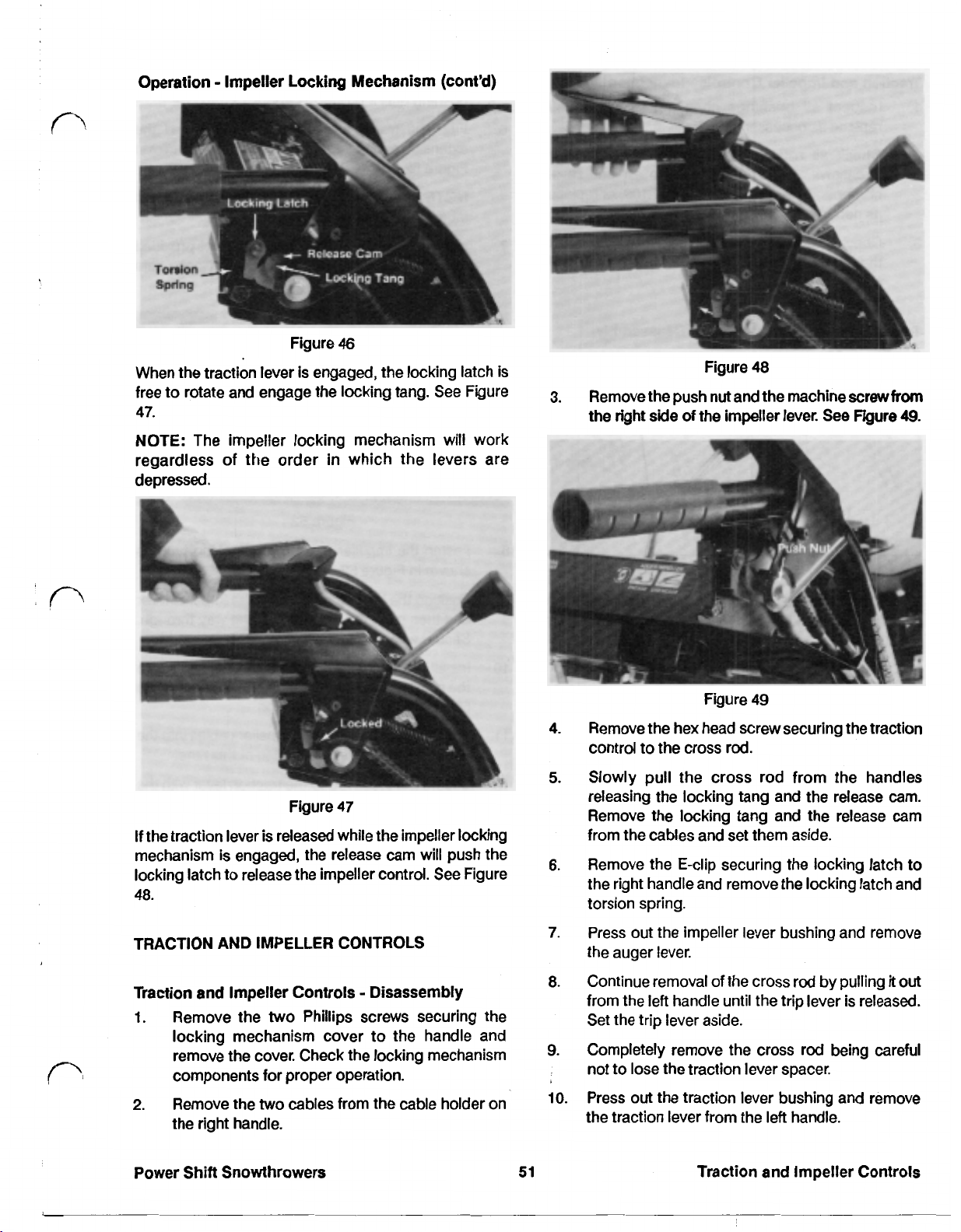
OPERATION
Operation Traction Control
Traction is controlled by means of the lever on top of the
left
handle. See Figure
44.
The lever is spring loaded in
the disengaged position. The transmission can be
engaged by pushing down on the lever.
Impeller
Lever
Traction
Lever
Figure
45
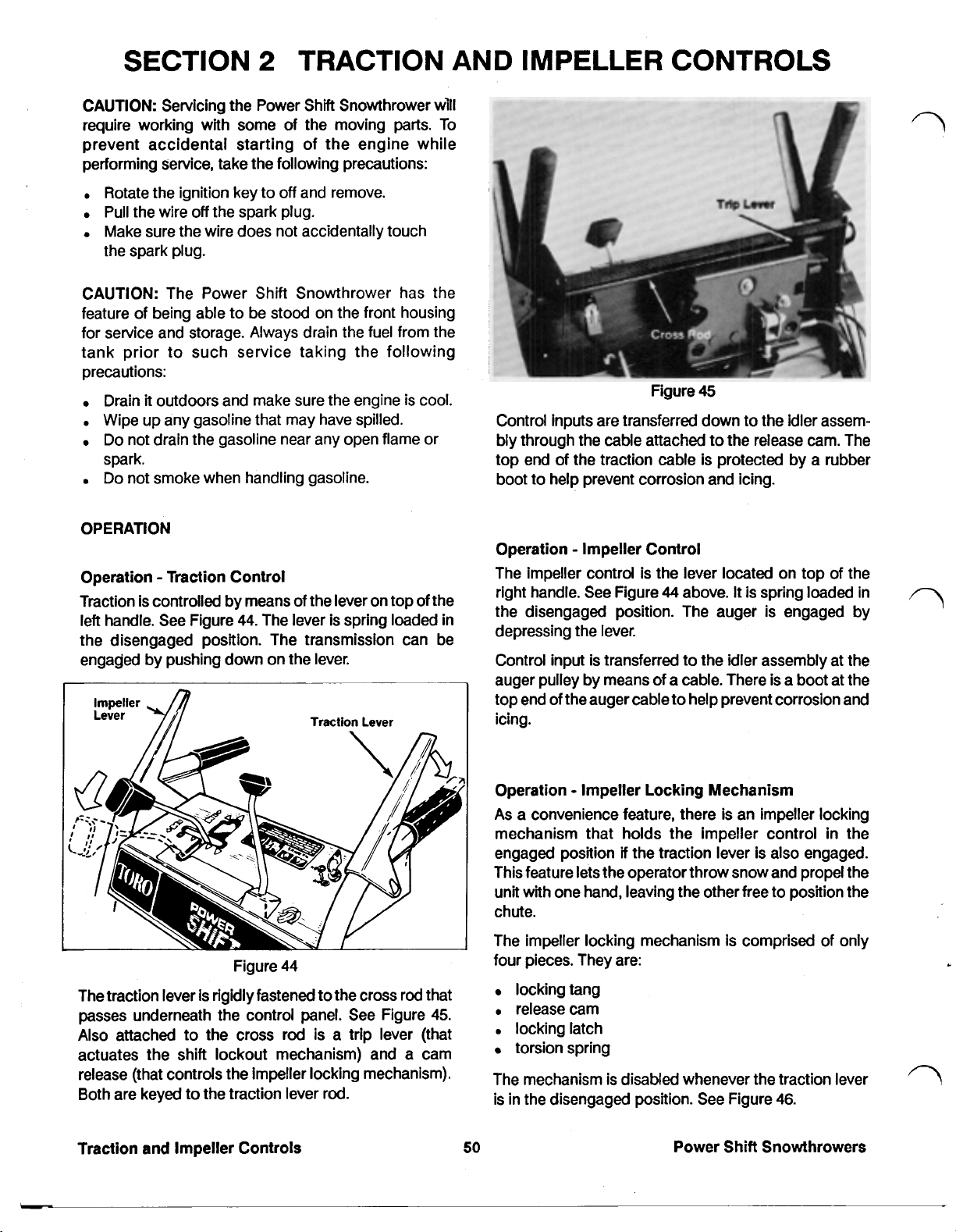
Control inputs are transferred down to the idler assembly through
the
cable attached to the release cam. The
top end of the traction cable is protected by a rubber
boot to help prevent corrosion and icing.
Operation Impeller Control
The impeller control is the lever located on top of the
right handle. See Figure
44
above.
It
is spring loaded in
the disengaged position. The auger is engaged by
depressing the lever.
Control input is transferred to the idler assembly at the
auger pulley by means of
a
cable. There is a boot at the
top end of the auger cable to help prevent corrosion and
icing.
Figure
The traction lever
is
rigidly fastened to the cross rod that
passes underneath the control panel. See Figure
44
45.
Also attached to the cross rod is a trip lever (that
actuates the shift lockout mechanism) and a cam
release (that controls the impeller locking mechanism).
Both are keyed to the traction lever rod.
Traction and Impeller Controls
Operation Impeller Locking Mechanism
As
a convenience feature, there is an impeller locking
mechanism that holds the impeller control in the
if
engaged position
the traction lever is also engaged.
This feature lets the operator throw snow and propel the
unit with one hand, leaving the other free to position the
chute.
The impeller locking mechanism
is
comprised of only
four pieces. They are:
locking tang
release cam
locking latch
torsion spring
The mechanism is disabled whenever the traction lever
is in the disengaged position. See Figure
50
Power Shift Snowthrowers
46.
Page 58
Operation Impeller
When the traction lever is engaged, the locking latch is
free to rotate and engage the locking tang.
47.
NOTE: The impeller locking mechanism will work
regardless of the order
depressed.
Locking
Figure
in
Mechanism (cont’d)
46
See
Figure
which the levers are
Figure
48
3.
Remove the push nut and the machine screw
the
right side of the impeller lever. See Figure
from
49.
Figure
If the traction lever is released while the impeller locking
mechanism
locking latch to release the impeller control. See Figure
48.
TRACTION AND IMPELLER CONTROLS
Traction and Impeller Controls Disassembly
1.
locking mechanism cover to the handle and
remove the cover. Check the locking mechanism
components for proper operation.
2.
Remove the
the right handle.
is
engaged, the release cam will push the
Remove the
two
two
cables from the cable holder on
47
Phillips screws securing the
Figure
Remove the hex head screw securing the traction
4.
control to the cross rod.
Slowly pull
5.
releasing the locking tang and the release cam.
Remove the locking tang and the release cam
from the cables and set them aside.
Remove the E-clip securing the locking latch to
6.
the right handle and remove the locking latch and
torsion spring.
Press out the impeller lever bushing and remove
7.
the auger lever.
Continue removal of the cross rod by pulling
a.
from the
Set the trip lever aside.
Completely remove the cross rod being careful
9.
not to lose the traction lever spacer.
Press out the traction lever bushing and remove
10.
the traction lever from the
the
left
handle until the trip lever is released.
49
cross rod from the handles
left
handle.
it
out
Power Shift Snowthrowers
51
Traction and Impeller Controls
Page 59

Traction and Impeller Controls Inspection
1.
Inspect all bushings checking for wear and
replace as necessary.
2.
Check all rotating parts for corrosion and/or
excessive wear. Lubricate with an anti-seize
compound (Toro
part
number
505-109)
or replace
as necessary.
3.
Check the trip lever and release cam to insure that
the keys securing them to the cross rod are still
intact.
Traction and Impeller Controls Reassembly
See Figure
50.
5.
Push the cross rod through the impeller lever
bushing until
6.
Find the traction cable and install
it
protrudes-about
13
mm
extension spring into the release cam as shown in
Figure
52.
NOTE: The recessed side of the release
face the control panel.
7.
Hook the extension spring into the slot provided
in the right handle then mount the release cam
onto the cross rod.
(1/2").
it
and the
cam
will
Figure
50
1.
Position the traction lever in
the
left
handle and press in the traction lever
its
normal location on
bushing.
NOTE: The traction lever bushing is reversible.
2.
Place
the
traction lever spacer inside the traction
lever and insert the cross rod through the traction
lever.
3.
Install the trip lever onto the cross rod as shown
in Figure
51.
Figure
8.
Fasten the impeller cable to the locking tang
shown in Figure
9.
Position the locking tang inside the impeller lever
52.
52
and then push the cross rod all the way through.
Secure with the Phillips screw.
10.
Install
the
torsion spring and the lock latch onto
the spindle and secure with the E-clip. See Figure
52
for proper spring orientation.
11.
Position both traction and impeller cables into the
cable holder,
12.
Secure the cross rod to the traction lever with the
but
do not tighten at this time.
hex head screw and locknut.
13.
Before assembling any further, verify that
everything works as described under Traction
and Impeller Controls Operation, page
14.
Install a new push nut on the right end of the cross
rod. Be sure to align the tabs in the push nut
from the keyway to insure retention.
15.
Install the locking mechanism cover with the
screws.
as
50.
90"
two
Figure
51
Traction and Impeller Controls Traction Cable
Adjustment
4.
Position the impeller lever on the right handle and
press in the impeller lever bushing.
The
traction
system
power from the engine. Therefore, the belt doesn't
NOTE: The impeller lever bushing is reversible. require much tension to drive the wheels.
Traction and Impeller Controls
52
very
Power
little
of
the
Shift
Snowthrowers
A
available
Page 60

Traction and Impeller Controls Traction Cable
Adjustment (cont'd)
1.
Check for proper tension by pushing the front
housing
wall. Proper traction belt tension is achieved when
the wheels spin on a concrete floor in second gear,
but do not in fourth.
2.
Adjust tension by loosening the two jam nuts at
the upper end of the traction cable. To increase
tension, rotate the nuts
sheath moves down. To decrease tension, the end
of the sheath must be moved closer to the traction
lever.
of
the snowthrower against a protected
so
that the
end
of
the
.23
mm to
.30
mm
(.009”
to
.012")
CAUTION:
cause the snowthrower to creep when the
traction lever is
Traction and Impeller Controls Impeller Cable
Adjustment
The impeller drive system will in some conditions
transmit most of the power available from the engine.
Therefore the tension
1.
Depress the impeller lever. Proper tension is
achieved when there is
between coils
Figure
53.
Do
not overtighten because
in
the disengaged position.
on
this belt is fairly high.
.25
mm
(.010”)
of
the impeller cable spring.
it
may
clearance
See
Figure
2.
Adjust tension by loosening the
the top of the auger cable. Increase tension by
rotating the nuts
moves down. Decrease tension by moving the
end of the sheath toward the impeller lever.
NOTE: Do not overtighten as
impeller and auger to turn when the lever is in the
disengaged position.
53
so
that the end
two
of
it
may cause the
jam nuts at
the sheath
Power Shift Snowthrowers
53
Traction and Impeller Controls
Page 61

CAUTION: Servicing the Power Shift Snowthrower will
require working with some of the moving parts. To
prevent accidental starting of the engine while
performing service, take the following precautions:
Rotate the Ignition key to
Pull the wire
Make sure the wire does not accidentally touch
the spark plug.
CAUTION: The Power Shift Snowthrower has the
feature of being able to be stood on the front housing
for service and storage. Always drain the fuel
tank prior to such service taking the following
precautions:
Drain
it
Wipe up any gasoline that may have spilled.
Do
not drain the gasoline near any open flame or
spark.
Do not smoke when handling gasoline.
CHUTE CONTROL
Chute Control Operation
The control for the discharge chute of the Toro Power
Shift Snowthrower was designed
would turn
rotated.
See
off
the spark plug.
outdoors and make sure the engine is cool.
In
the same direction that the input knob was
Figure
54.
off
and remove.
so
from
that the chute
the
The chute rotates from extreme
200
arc of
Chute Control Knob Removal
NOTE:
I.
2.
3.
Chute Control Knob Installation
1.
degrees in about six turns of the crank.
Do
not remove
To remove the knob, use a pocket knife to pry
the square knob cover.
Remove the push nut by drilling through the
tabs in the pushnut and prying
Remove the knob.
Install the knob on the
the
Figure
left
to right through an
knob unless necessary.
See
Figure
55
off.
rod,
recessed side
off
55.
two
up.
Figure
The operator provides control input by turning the chute
control knob at the control panel. This rotation is
transmitted to the chute by means of a constant velocity
joint and
which drives the teeth on the chute.
two
shafts. The final shaft turns a worm gear
54
54
2.
Press on a new pushnut using an
socket.
3.
Reinstall the knob cover using a small amount of
clear silicone
Chute Control Upper
1.
Remove the
56.
NOTE: Do not remove the knob unless necessary.
2.
Pull the upper
control panel. Do not lose the rubber washer
above the gear.
3.
If desired, remove the upper
removing the
control panel.
if
necessary.
Rod
Removal
roll
pin in the upper gear. See Figure
rod
assembly out through the
two
Phillips screws from beneath the
Power Shift Snowthrowers
11
rod
bushing by
mm
(7/16'”)
Page 62

Chute Control
Upper
Rod
Removal
(cont'd)
3.
Slide the upper rod through the bracket then slip
the rubber washer on the end of the rod. Install
the gear on
4.
Secure the gear with the roll pin.
the
rod with the teeth facing down.
Chute Control Upper
See Figure
57.
Figure
Rod
56
Installation
Chute Control Lower
1.
Remove the roll pin from the lower rod gear.
2.
Pull
the rod from the worm gear bracket and then
forward to remove
3.
If desired, remove the worm gear bracket.
Chute Control Lower
See Figure
58.
Rod
it
from
Rod
Figure
Removal
the bracket.
Installation
58
Figure
1.
Mount the upper rod bushing on the control panel.
2.
Slide the upper rod assembly through the control
panel from the top.
57
1.
Loosely mount the worm gear bracket with the
carriage bolt, washer and locknut.
Insert the lower rod into the joint bracket.
2.
Place the worm gear in the worm gear bracket and
3.
slide the lower rod into
4.
Install the lower rod gear with the teeth facing
rear of machine.
Adjust the worm gear bracket by pushing
5.
the
chute until the teeth on the chute and the worm
gear are just touching. Check for binding by
rotating the control knob.
move the worm gear bracket out slightly and
recheck.
DISCHARGE CHUTE
Discharge Chute Operation
CAUTION! Keep hands,
discharge chute area. The impeller at the bottom of the
discharge chute rotates rapidly and could cause severe
injury
if
contacted. If the chute should
it.
it
toward
If
binding is noticed,
feet
and loose clothing from the
the
Power Shift Snowthrowers
55
Discharge Chute
Page 63

Discharge Chute Operation (cont'd)
clog, always stop the engine, wait for all moving parts
to stop, disconnect spark plug lead and then use a tool,
such as a broom handle, to clear the obstruction.
Discharge Chute Removal
1.
Remove the three socket head machine screws at
the base of the chute.
2.
Remove the chute.
CAUTION!
chute guard in place.
inadvertent contact with the impeller.
Do
not operate the snowthrower without the
It
is there to help prevent
Discharge Chute Installation
See Figure
CAUTION! When throwing snow, never direct the
discharge at people, pets or personal property as debris
or ice could
See Figure
The discharge chute rotates through an arc of
be
picked up and thrown.
59.
200"
for
convenient directioning of snow while throwing.
The chute rotates on a ring that is welded to the front
housing assembly. Three retainers hold the chute on the
ring and allow
it
to rotate.
Directional changes are the result of manual inputs from
the operator and are transmitted through the control rod
assembly and the worm gear. The chute itself has teeth
manufactured into
it
which mate
with
the worm gear.
60.
Figure
59
The chute deflector is hinged and gives the operator
greater control over the vertical and horizontal
distances the snow is thrown.
A
piano hinge is used to
reduce the amount of snow blown through the hinge.
Nylon washers hold the top of the chute in position and
allow
it
to be moved without the use of tools when the
locknut is properly tightened.
The chute deflector is not removable or replaceable
separately.
Figure
1.
Lightly grease the chute ring with a
60
#2
lithium
base grease.
2.
Loosen the nut under the worm gear bracket to
facilitate installation of the chute.
Place the chute on the chute ring with the
3.
facing
forward.
Install
the
two
rear chute retainers
chute
using socket head machine screws and nylon
locknuts.
Install the front chute retainer being sure that the
4.
chute guard is trapped by the chute guard
bracket.
Adjust the worm gear bracket by pushing
5.
it
toward
the chute until the teeth on the chute and the worm
gear are just touching. Check for binding by
rotating the control knob.
If
binding is noticed,
move the worm gear bracket out slightly and
recheck.
Discharge Chute
56
Power Shift Snowthrowers
Page 64
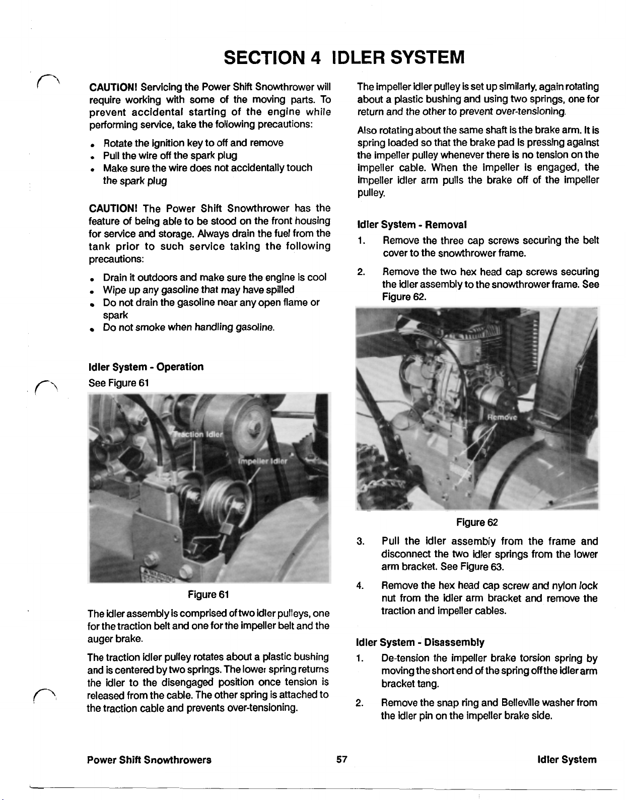
SECTION
IDLER SYSTEM
4
CAUTION! Servicing the Power
require working with some of the moving parts. To
prevent accidental starting of the engine while
performing service, take the following precautions:
Rotate the ignition key to
Pull the wire
Make sure the wire does not accidentally touch
the spark plug
CAUTION! The Power Shift Snowthrower has the
feature of being able to be stood on the front housing
for service and storage. Always drain the fuel from the
tank prior to such service taking the following
precautions:
Drain
Wipe up any gasoline that may have spilled
Do not drain the gasoline near any open flame or
spark
Do not smoke when handling gasoline
Idler System Operation
See Figure 61
off
the spark plug
it
outdoors and make sure the engine is cool
Shift
off
and remove
Snowthrower will
The impeller idler pulley is set up similarly, again rotating
about a plastic bushing and using
return and the other to prevent over-tensioning.
Also
rotating about the same shaft is the brake arm.
so
spring loaded
the
impeller pulley whenever there is no tension on the
impeller cable. When the impeller is engaged, the
impeller idler arm pulls the brake
pulley.
Idler
System Removal
1. Remove the three cap screws securing the belt
cover to the snowthrower frame.
2. Remove the
the idler assembly to the snowthrower frame.
Figure 62.
that the brake pad is pressing against
two
hex head cap screws securing
two
springs, one for
off
of the impeller
It
is
See
3.
Figure 61
two
The idler assembly is comprised of
for the traction belt and one for the impeller belt and the
auger brake.
The traction idler pulley rotates about a plastic bushing
two
and is centered by
the idler to the disengaged position once tension is
released from the cable. The other spring is attached to
the traction cable and prevents over-tensioning.
Power Shift Snowthrowers
springs. The lower spring returns
idler pulleys, one
4.
Idler System Disassembly
1.
2.
57
Figure 62
Pull the idler assembly from the frame and
two
disconnect the
arm bracket. See Figure
Remove the hex head cap screw and nylon lock
nut from the idler arm bracket and remove the
traction and impeller cables.
De-tension the impeller brake torsion spring by
moving the short end of
bracket tang.
Remove the snap ring and Belleville washer from
the
idler pin on the impeller brake side.
idler springs from the lower
63.
the
spring
off
the idler arm
Idler System
Page 65

Idler System Disassembly (cont'd)
1.
Insert a hex head cap screw into each of the idler
pulleys.
Figure
CAUTION !
Eye protection and heavy gloves are
recommended when installing spring.
Check the impeller pulley brake pad for excessive
3.
wear and remove if necessary. Remove by
grasping with a needle nose plyers and rotating.
Pull the idler pin from the idler arm bracket and
4.
remove the
Remove the
5.
arms.
Remove the fastener retaining the cables and
6.
remove the cables.
The torsion spring is under tension.
two
idler arms.
two
idler return springs from the idler
63
NOTE:
the short race of each idler pulley bearing.
Secure with the nylon locknuts and check for free
rotation of each idler pulley
2.
Mount the
using Figure
3.
Insert the
secure with the idler pin using Figure
guide.
4.
Hook the
holes on the idler arms.
5.
If
apply a small amount
arm and install the brake pad.
6.
Slip the torsion spring into the brake arm with the
short side of the spring on the opposite end of the
brake pad. Slip onto the idler pin and secure with
a
NOTE:
time.
7.
Grasp the short end
needle nose plyers and slip into the tang on the
idler arm bracket.
See Figure
The head of each cap screw must be on
two
idler arms onto the idler bushing
64
as a guide.
two
idler arms into the idler bracket and
two
idler return springs into the lower
the impeller pulley brake pad was removed,
of
adhesive onto the brake
belt,
washer and snap ring.
Do
not attempt to tension the spring at this
of
the torsion spring with a
65
64
as a
Remove the idler bushing from the idler arm pivots
7.
and inspect for wear. Replace
Check the traction idler pulley and impeller idler
8.
pulleys for free rotation on the idler arms.
necessary, remove and replace the pulleys.
Idler System Reassembly
See Figure
64.
Figure
64
if
necessary.
If
Figure
CAUTION!
Eye protection and heavy gloves should be worn
when performing this procedure.
Idler System Installation
1.
Find the impeller cable and insert the spring end
into the upper hole on the impeller idler arm, then
slip the end of the impeller cable sheath into the
slot provided at the top
The torsion spring is under tension.
65
of
the idler bracket.
Power Shift Snowthrowers
Page 66
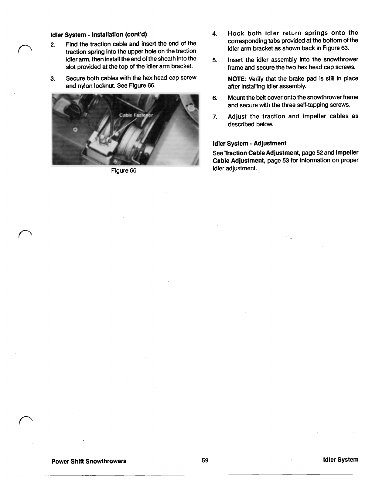
Idler System Installation (cont’d)
2.
Find the traction
cable
and insert the end of the
traction spring into the upper hole on the traction
idler arm, then install the end of the sheath into the
slot provided at the top of the idler arm bracket.
3.
Secure both cables with the hex head cap screw
and nylon locknut. See Figure
Figure
66.
66
4.
Hook both idler return springs onto the
corresponding tabs provided at the bottom of the
idler arm bracket as shown back in Figure
5.
Insert the idler assembly into the snowthrower
frame and secure the
NOTE:
Verify that the brake pad is still in place
two
hex head
cap
screws.
after installing idler assembly.
6.
Mount the belt cover
onto
the snowthrower frame
and secure with the three self-tapping screws.
7.
Adjust the traction and impeller cables
described below.
Idler
System Adjustment
52
See Traction Cable Adjustment, page
Cable Adjustment, page
53
for information on proper
and Impeller
idler adjustment.
63.
as
Power Shift Snowthrowers
59
Idler System
Page 67
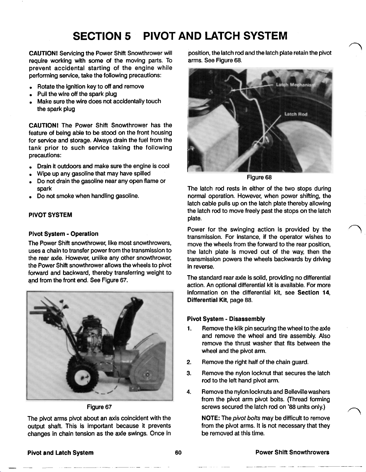
SECTION
5
PIVOT AND LATCH SYSTEM
CAUTION! Servicing the Power Shift Snowthrower will position, the latch rod and the latch plate retain
require working with some of the moving
prevent accidental starting of the engine while
performing service, take
Rotate the ignition key to
Pull the wire
Make sure the wire does not accidentally touch
the spark plug
CAUTION! The Power Shift Snowthrower has the
feature of being able to
for service and storage. Always drain the fuel from the
tank prior to such service taking the following
precautions:
Drain
Wipe up any gasoline that may have spilled
Do not drain the gasoline near any open flame or
spark
Do
not smoke when handling gasoline.
PIVOT SYSTEM
off
it
outdoors and make sure the engine is cool
the
following precautions:
off
and remove
the spark plug
be
stood on the front housing
parts.
To arms. See Figure
The latch rod rests in either of the
normal operation. However, when power shifting, the
latch cable pulls up on the latch plate thereby allowing
the latch rod to move freely past the stops on the latch
plate.
68.
Figure
68
two
stops during
the
pivot
Pivot System Operation
The Power Shift snowthrower, like most snowthrowers,
uses a chain to transfer power from the transmission to
the rear axle. However, unlike any other snowthrower,
the Power Shift snowthrower allows the wheels to pivot
forward and backward, thereby transferring weight to
and from the front end. See Figure
Figure
67.
67
Power for the swinging action is provided by the
transmission. For instance,
move the wheels from the forward to the rear position,
the latch plate
transmission powers the wheels backwards by driving
in reverse.
The standard rear axle is solid, providing no differential
action. An optional differential
information on the differential kit, see Section
Differential Kit, page
Pivot System Disassembly
1.
Remove the klik pin securing the wheel to the axle
and remove the wheel and tire assembly. Also
remove the thrust washer that fits between the
wheel and the pivot arm.
2.
Remove the right half of the chain guard.
3.
Remove the nylon locknut that secures the latch
rod to the
4.
I
Remove the nylon locknuts and Belleville washers
from the pivot arm pivot bolts. (Thread forming
screws secured the latch rod on
is
moved out of the way, then the
88.
left
hand pivot arm.
if
the operator wishes to
kt
is available. For more
'88
units only.)
14,
The pivot arms pivot about an axis coincident with the
output shaft. This is important because it prevents
changes in chain tension as the axle swings. Once in
Pivot and Latch System
60
NOTE: The
from the pivot arms. It
be removed at this time.
pivot
bolts
may be difficult to remove
is
Power
not necessary that they
Shift
Snowthrowers
Page 68

Pivot System Disassembly (cont’d)
5.
Remove the left hand pivot arm complete with the
chain guard.
6.
Remove the latch rod, pivot arm, and rear axle
assembly by slipping the chain
off
sprocket.
7.
Remove chain guard from the
8.
Remove the latch rod from
left
hand pivot arm.
the
right hand pivot
arm.
9.
If necessary, remove the bushings from the pivot
arms using an arbor press.
If
10.
desired, remove the pivot bolts. They may flare
somewhat once installed and may have to be
pressed out with an arbor press.
11.
If
necessary, remove the roll pins from the axle.
Pivot System Reassembly
See
Figure
69.
the large
6.
Insert the latch rod, pivot arm, and axle assembly
into the proper location on the right side of the
chassis. Be sure to slip the chain over the
sprocket.
NOTE: There must be a Belleville washer between
the frame and the pivot arm. The serrated side of
the Belleville washer should face
7.
Slide the
left
pivot arm and chain guard assembly
the
pivot arm.
over the axle and into position.
NOTE: Make sure all washers are in place. There
should be a Belleville washer (serrated side
toward the pivot arm) between the pivot arm
the chassis, a large flat washer (between the end
of the latch rod and the pivot arm), and a thrust
washer between the roll pin and the pivot arm
when
it
is installed correctly. See Figure
and
70.
8.
Secure the assembly by tightening the pivot arm
bolts and nuts, and the nuts on the latch rod.
9.
Mate the right half of the chain guard with the
half and secure with the three Phillips screws.
Figure
69
10. Coat the end of the axle with an anti-seize
compound Toro part number 505-109).
1.
Press new bushings into both pivot arms.
2.
Install the chain guard on the left hand pivot arm.
apply in the bushing area as
“gummy”.
11. Slide the thrust washers over the end of the
3.
Press roll pins into the two inner holes on the axle
and slide thrust washers on each end
so
that they
rest against the roll pins.
4.
Install the latch rod into the right hand pivot arm, Secure the wheels with the klik pin. Use the outer
making sure that there is a large flat washer on hole
each side of the pivot arm. Don’t tighten the nylon hole
and install the wheel assemblies. Note that the
part of the hub with the hole in
Rotate wheel to distribute anti-seize compound,
if
free wheeling is desired, or use the inner
if
drive is desired.
locknut at this time.
5.
Insert the axle into the right pivot arm and latch
rod assembly. The sprocket will be on the
of the axle when
it
is installed correctly. Latch System Disassembly
left
side
LATCH
SYSTEM
Figure
70
Do
it
may become
it
faces outward.
left
not
axle
NOTE: Make sure there is
between the roll
Power
Shift
Snowthrowers 61 Pivot and
pin
a
thrust washer 1. Remove the panel fastener from the latch plate
and the pivot arm. and slip out the end of the latch cable.
Latch
System
Page 69

Latch System Disassembly
2.
Pull the latch plate down to detension the latch
plate spring, then remove the nylon locknuts on
either side of the latch plate.
3.
Remove the latch plate and latch plate spring from
the snowthrower frame.
Latch System Reassembly
See Figure
71
2.
Place the latch plate in position.
3.
Secure the latch plate with the
two
shoulder bolts
and the nylon locking nuts. Make sure that the
head of the bolts are on the inside of the frame.
4.
Swing the latch plate up into position and slip the
cable into the slot provided. Secure the cable with
a
new panel fastener. See Figure
Figure
72
72.
Figure
71
1.
Position the latch plate spring on the right side
the frame.
of
5.
Check to insure that the latch plate operates
correctly and does not bind.
6.
Complete latch plate servicing by reassembling
the pivot and drive assembly as described under
Pivot System Reassembly, page
61.
Pivot
and
Latch System
~-
Page 70
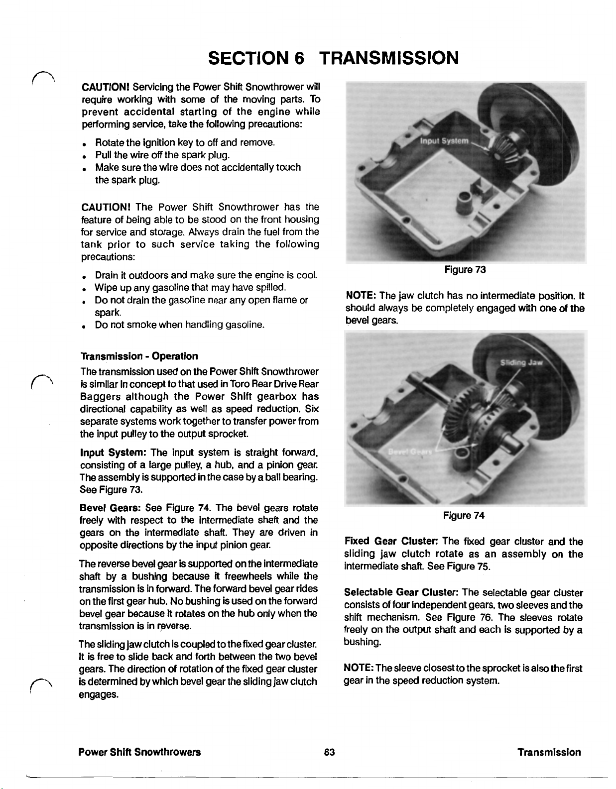
SECTION
CAUTION! Servicing the Power Shift Snowthrower will
require working with some of the moving
prevent accidental starting of the engine while
performing service, take the following precautions:
6
parts.
TRANSMISSION
To
Rotate the ignition key to
Pull the wire
Make sure the wire does not accidentally touch
the spark plug.
CAUTION! The Power Shift Snowthrower has the
feature of being able to be stood on the front housing
for service and storage. Always drain the fuel from the
tank prior to such service taking the following
precautions:
Drain
it
Wipe up any gasoline that may have spilled.
Do not drain the gasoline near any open flame or
spark.
Do not smoke when handling gasoline.
Transmission Operation
The transmission used on the Power Shift Snowthrower
is similar in concept to that used in Toro Rear Drive Rear
Baggers although the Power Shift gearbox has
directional capability as well as speed reduction. Six
separate systems work together to transfer power from
the input pulley to the output sprocket.
off
the spark plug.
outdoors and make sure the engine is cool.
off
and remove.
Figure
NOTE: The jaw clutch has no intermediate position.
should always
bevel gears.
be
completely engaged with one
73
of
It
the
Input
System: The input system is straight forward,
consisting of a large pulley, a hub, and a pinion gear.
The assembly is supported in the case by a
See Figure
Bevel Gears: See Figure
freely with respect to the intermediate shaft and the
gears on the intermediate shaft. They are driven in
opposite directions by the input pinion gear.
The reverse bevel gear is supported on the intermediate
shaft by a bushing because
transmission is in forward. The forward bevel gear rides
on the first gear hub.
bevel gear because it rotates on the hub only when the
transmission is in reverse.
The sliding jaw clutch is coupled to the fixed gear cluster.
It
is free to slide back and forth between the two bevel
gears. The direction of rotation of
is determined by which bevel gear the sliding jaw clutch
engages.
73.
74.
The bevel gears rotate
it
freewheels while the
No
bushing is used on the forward
the
ball
bearing.
fixed gear cluster
Fixed Gear Cluster: The fixed gear cluster and the
sliding jaw clutch rotate as an assembly on the
intermediate shaft. See Figure
Selectable Gear Cluster: The selectable gear cluster
consists of four independent gears, two sleeves and the
shift mechanism.
freely on the output shaft and each is supported by a
bushing.
NOTE: The sleeve closest to the sprocket
gear in the speed reduction system.
See
Figure
Figure
74
75.
76.
The sleeves rotate
is
also the first
Power Shift Snowthrowers
63
Transmission
Page 71

Transmission Operation (cont'd)
and number three speed reduction gears. Gears
and three are joined and therefore rotate at the same
speed.
The number three speed reduction gear transmits
power to
four gear and the output shaft are splined together,
power is transmitted to the output shaft and sprocket.
NOTE: The number four speed reduction gear is the
only component on the output shaft that
the output
the
number four gear. Because the number
is
shaft.
coupled to
two
Figure
The four gears are driven by the gears opposite them
on the intermediate shaft. The selectable gears rotate
freely on the sleeves when the transmission is in neutral.
However, when the transmission is in gear, the shift
mechanism engages
and the sleeves rotate together.
Shift Mechanism: See Figure
consists of
collar and the shift fork. Control input from the operator
rotates the shift fork
desired gear.
Speed Reduction Gear Set: In order to bring the speed
of the transmission down to one acceptable for
snowthrowing, a speed reduction gear set was
incorporated. See Figure
The first gear in the speed reduction gear set is also the
sleeve in which the shift keys slide. Therefore, when the
transmission is in gear, the number one speed reduction
gear rotates. This transmits power to the number
two
one
sliding shift keys, a shift sleeve, a shift
so
76
of the gears
77.
that the sliding keys engage the
78.
so
that the gear
The shift mechanism
two
Transmission Removal
NOTE:
steps, the use of air tools is recommended. However,
do not use air tools to tighten or loosen self-tapping
screws in aluminum. Thread damage could result.
1.
Figure
Figure
Because transmission removal requires many
Stand the unit on the front housing to provide
better access to the transmission. Don't forget to
drain the fuel first as described at the beginning of
this section.
77
78
Transmission
64
Power Shift Snowthrowers
Page 72
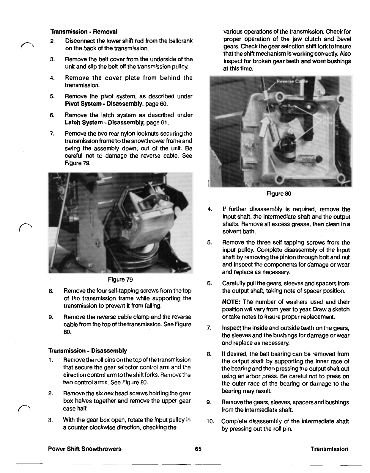
Transmission Removal various operations of the transmission. Check for
2.
Disconnect the lower shift rod from the bellcrank proper operation of the jaw clutch and bevel
on the back of the transmission. gears. Check the gear selection shift fork to insure
that the shift mechanism is working correctly.
3.
Remove the belt cover from the underside of the inspect for broken gear teeth and-worn bushings
off
unit and slip the belt
4.
Remove the cover plate from behind the
the transmission pulley. at this time.
transmission.
5.
Remove the pivot system, as described under
Pivot
System Disassembly, page
6.
Remove the latch system as described under
Latch System Disassembly, page
7.
Remove the
transmission frame to
two
rear nylon locknuts securing the
the
snowthrower frame and
60.
61.
swing the assembly down, out of the unit. Be
careful not to damage the reverse cable.
Figure
79.
See
Figure
80
Also
4.
If
further disassembly is required, remove the
input shaft, the intermediate shaft and the output
shafts. Remove all excess grease, then clean in a
solvent bath.
5.
Remove the three self tapping screws from the
input pulley. Complete disassembly of the input
shaft by removing the pinion through bolt and nut
and inspect the components for damage or wear
and replace as necessary.
Figure
8.
Remove the four self-tapping screws from the top the output shaft, taking note of spacer position.
of the transmission frame while supporting 'the
transmission to prevent
9.
Remove the reverse cable clamp and the reverse or take notes to insure proper replacement.
cable from the top of
80.
79
it
from falling.
the
transmission*
See
Figure
6.
Carefully pull the gears, sleeves and spacers from
NOTE:
The number of washers used and
position will vary from year to year. Draw a sketch
7.
Inspect the inside and outside teeth on the gears,
the sleeves and the bushings for damage or wear
and replace as necessary.
Transmission Disassembly
1.
Remove the roll pins on the top
of
the transmission
that secure the gear selector control arm and the
direction control arm to the shift forks. Remove the
two
control arms.
2.
Remove the six hex head screws holding the gear
See
Figure
80.
box halves together and remove the upper gear
case half.
3.
With the gear
a
counter clockwise direction, checking the by pressing
box
open, rotate the input pulley in
8.
If
desired, the ball bearing can be removed from
the output shaft by supporting the inner race of
the bearing and then pressing the output shaft out
using an arbor press. Be careful not to press on
the outer race of the bearing or damage to the
bearing may result.
9.
Remove the gears, sleeves, spacers and bushings
from the intermediate shaft.
10.
Complete disassembly of the intermediate shaft
out
the roll pin.
their
Power Shift Snowthrowers
65
Transmission
Page 73
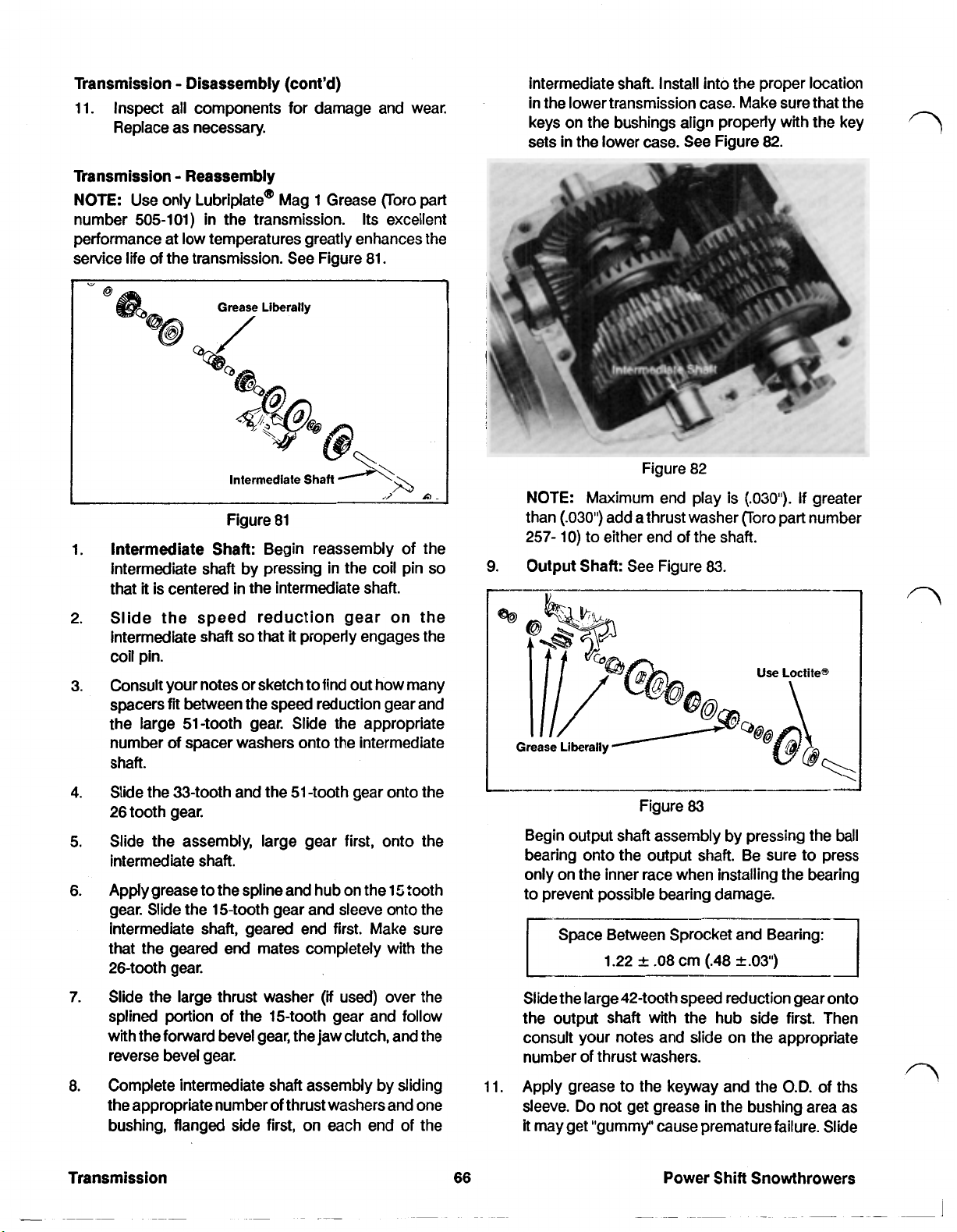
Transmission Disassembly (cont'd)
11. Inspect all components for damage and wear.
Replace as necessary.
Transmission Reassembly
NOTE: Use only Lubriplate@ Mag 1 Grease Toro part
number 505-101) in the transmission. Its excellent
performance at low temperatures greatly enhances the
service life of the transmission. See Figure 81.
intermediate shaft. Install into the proper location
in
the
lower transmission case. Make sure that the
keys on the bushings align properly with the key
sets in the lower case. See Figure
82.
Figure 82
Figure 81
Intermediate Shaft: Begin reassembly of the
1.
Intermediate shaft by pressing in the coil pin
that
it
is centered in the intermediate shaft.
2.
Slide the speed reduction gear on the
so
that
it
intermediate shaft
properly engages the
coil pin.
Consult your notes or sketch to find out how many
3.
spacers fit between the speed reduction gear and
the large 51-tooth gear. Slide the appropriate
number of spacer washers onto the intermediate
Shaft.
Slide the 33-tooth and the 51 -tooth gear onto the
4.
26 tooth gear.
Slide the assembly, large gear first, onto the
5.
intermediate shaft.
Apply grease to the spline and hub on the 15 tooth
6.
gear. Slide the 15-tooth gear and sleeve onto the
intermediate shaft, geared
end
first. Make sure
that the geared end mates completely with the
26-tooth gear.
so
NOTE: Maximum end play is
than
(.030")
add a thrust washer (Toro part number
(.030").
If greater
257- 10) to either end of the shaft.
9.
Output
Shaft: See Figure
Figure
83
83.
Begin output shaft assembly by pressing the
bearing onto the output shaft. Be sure to press
only on the inner race when installing the bearing
to prevent possible bearing damage.
Space Between Sprocket and Bearing:
1.22
-08
cm (.48
2.03')
ball
7.
Slide the large thrust washer
)if
used) over the
splined portion of the 15-tooth gear and follow
with the forward bevel gear, the jaw clutch, and the
reverse bevel gear.
Complete intermediate shaft assembly by sliding
8.
the appropriate number
bushing, flanged side first, on each end
of
thrust washers and one
of
the
Transmission
66
Slide the large 42-tooth speed reduction gear onto
the output shaft with the hub side first. Then
consult your notes and slide on the appropriate
number of thrust washers.
11.
Apply grease to the keyway and the
Do
sleeve.
it
may get "gummy" cause premature failure. Slide
not get grease in the bushing area as
O.D.
of ths
Power Shift Snowthrowers
Page 74

Transmission Reassembly
the
first half of the shift sleeve with the 19-tooth
gear onto the output shaft, geared end first.
Slide the four selectable gears onto the output
12.
83
shaft as shown in Figure
Apply grease to second sleeve half then slide onto
13.
the output shaft, flanged end last. Make sure that
the tabs properly engage the recesses
19-tooth gear sleeve. When properly assembled,
the outer sleeve half and the 15-tooth gear will turn
together.
above.
on
the
19. Assemble the input pinion, ball bearing, hub and
pulley as shown in Figure
85.
Assemble the shift mechanism consisting
14.
sleeve, the
grease to the shift collar groove.
Slide the shift mechanism, shift keys first,
15.
output shaft and into the appropriate slots
gear sleeves.
Complete assembly of the output shaft by
16.
installing the correct number of spacers and the
output bushing, flanged end first.
Install the assembled output shaft into the lower
17.
transmission case. Use Loctite(R) (Toro part
number 505-103) to secure the outer race of the
bearing to lower gearcase. Check for proper
operation of the various components, making
sure that there is neither excessive play nor
binding.
lower case.
install the
18.
Make sure that both shift collar grooves have been
greased.
two
shift keys and
Align
the bushing keys with keysets in the
two
shift forks as shown in Figure 84.
the
shift collar. Apply
of
onto
in
the
the
the
Figure
20. Use a small amount of Loctite(R) (Toro part
number 505-103) to secure the outer race of the
bearing to the lower gear case half. Be careful not
to get Loctite@ on the pinion or the hub.
21. Rotate the input pulley in a counterclockwise
direction and check for proper operation of the
entire transmission.
22. Apply (14.5 oz) of Lubriplate(R) Mag 1 grease (Toro
part
number
under gears first, then top. Also grease shift forks.
Install upper gear case half.
23. Press the gear selector control arm and the
directional control arm onto the shift forks
shown
in
Figure
505-101)
86.
85
to gears
in
transmission.
Fill
as
Power
Shift
Snowthrowers
Figure
84
67
Figure
86
Secure with the
Again, check to insure that the transmission
operates freely, then secure the
halves with the six self tapping hex head screws.
Coat screws with oil to prevent them from seizing.
two
roll pins.
two
1.38 kg m (120 in Ibs)
gear case
Transmission
Page 75

Transmission Installation
NOTE: Because of the number of steps involved, air
tools are recommended. However, do not use air tools
when installing or removing self-tapping screws from
aluminum. Damage to the threads could result.
Apply an anti-seize compound (Toro part number
1.
505-109)
to all pivot and contact points on top
of
the transmission including detent button, detent
box, link and bellcrank.
Before installing the transmission, check to be
2.
sure the input shaft and all controls on top of the
transmission are working correctly.
Insert the end of the reverse cable spring into the
3.
directional control arm and install the reverse
cable clamp.
Secure the transmission to the transmission frame
4.
with the four transmission screws and Belleville
washers (serrations up).
Fasten thetransmission frame to the snowthrower
5.
frame with the four hex head cap screws.
Slip the traction belt onto the transmission pulley.
6.
Install the latch plate as described under Latch
7.
System Installation, page 62.
Install the pivot and drive assembly as described
8.
under Pivot System Reassembly, page
Fasten the lower plastic belt cover to the frame
9.
using the
two
self tapping screws. The tabs on
61.
the edge of the cover should be located behind
the bulkhead plate.
10.
Place the transmission in second gear by pushing
the rear of the bellcrank to the top of
pulling down
Install the rear cover plate with 4 nylon lock nuts.
11.
Check chain adjustment, as described under
12.
2
clicks. See Figure
Figure
87
its
travel, then
87.
Maintenance Drive Chain Adjustment, page
38.
Install the lower shift rod into the bellcrank and
13.
adjust per instructions under Control
Service Shift Lever Adjustment, page
14.
Check latch cable adjustment as described under
Box
Control
49.
page
Check proper adjustment of the reverse cable as
15.
described under Control
Cable Adjustment, page
Service Latch Cable Adjustment,
Box
Service Reverse
49.
49.
Box
Power Shift Snowthrowers
Page 76
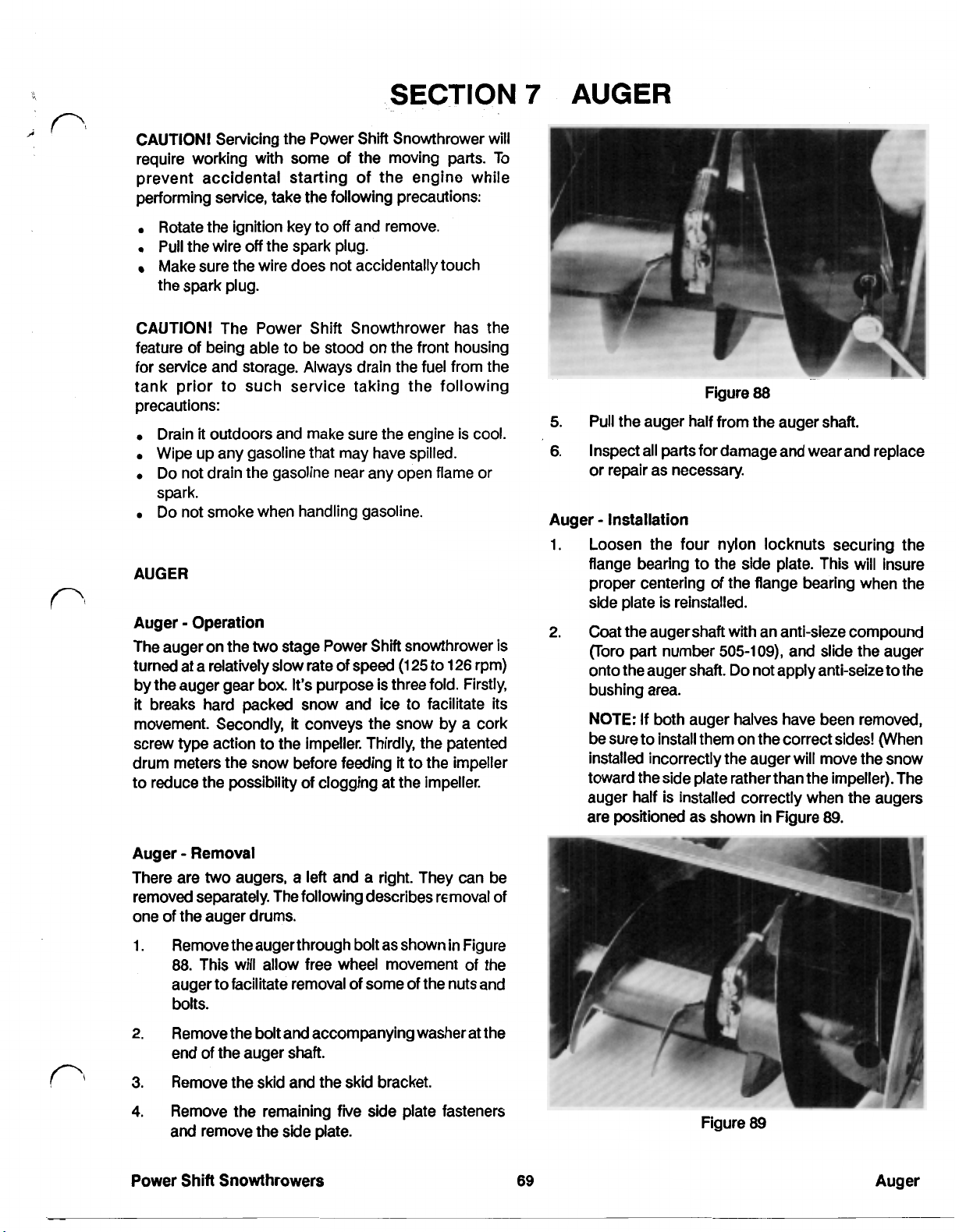
SECTION
CAUTION! Servicing the Power Shift Snowthrower will
require working with some of the moving parts. To
prevent accidental starting of the engine while
performing service, take the following precautions:
7
AUGER
Rotate the ignition key to
Pull
the wire
Make sure the wire does not accidentally touch
the spark plug.
CAUTION! The Power Shift Snowthrower has the
feature of being able to be stood on the front housing
for service and storage. Always drain the
tank prior to such service taking the following
precautions:
Drain
it
Wipe up any gasoline that may have spilled.
Do not drain the gasoline near any open flame
spark.
Do
not smoke when handling gasoline.
AUGER
Auger Operation
The auger on
turned at a relatively slow rate of speed
by the auger gear box. It’s purpose is three fold. Firstly,
it
breaks hard packed snow and ice to facilitate its
movement. Secondly,
screw type action to the impeller. Thirdly, the patented
drum meters the snow before feeding it to the impeller
to reduce the possibility of clogging at the impeller.
off
the spark plug.
outdoors and make sure the engine is
the
two
stage Power Shift snowthrower is
off
and remove.
fuel
from the
(125
to
126
it
conveys the snow by a cork
cool.
or
rpm)
Figure
5.
Pull the auger half from the auger shaft.
6.
Inspect all
or repair as necessary.
Auger Installation
1.
Loosen the four nylon locknuts securing the
flange bearing to the side plate. This will insure
proper centering of the flange bearing when the
side plate is reinstalled.
2.
Coat the auger shaft with an anit-seize compound
(Toro part number
onto the auger shaft. Do not apply anti-seize to the
bushing area.
NOTE:
be sure to install them on the correct sides! (When
installed incorrectly the auger will move the snow
toward the side plate rather than the impeller). The
auger half is installed correctly when the augers
are positioned as shown in Figure
parts
for damage and wear and replace
If
both auger halves have been removed,
88
505-109)
and slide the auger
89.
Auger Removal
There are
removed separately. The following describes removal
one of the auger drums.
1.
2.
3.
4.
Power Shift Snowthrowers
two
augers, a left and a right. They can be
Remove the augerthrough bolt as shown in Figure
88.
This will allow free wheel movement of the
auger to facilitate removal of some of the nuts and
bolts.
Remove the bolt and accompanying washer at the
end of the auger shaft.
Remove the skid and the skid bracket.
Remove the remaining five side plate fasteners
and remove the side plate.
of
69
Figure
89
Auger
Page 77

Auger Installation
Slide the side plate
3.
onto the auger shaft and secure with the top five
cap screws and lock nuts.
4.
Fasten the
housing and
(cont'd)
and
auger bearing assembly Tighten the four
skid
support bracket to the auger
loosely
install the
skid.
5.
Support
shaft is centered in the hole in the side plate.
6.
Secure the auger half to the auger shaft using the
long cap screw and nylon lock nut.
7.
Adjust the scraper and skids as described under
Skids Installation and Scraper Installation,
pages
78
the
and
auger
cap
79.
so
that the end
screws and nylon lock nuts.
of
the auger
70
Page 78

SECTION
8
AUGER GEAR
BOX
CAUTION! Servicing the Power
require working with some of the moving parts.
prevent accidental starting of the engine while
performing service, take the following precautions:
Rotate the ignition key to off and remove. 1. Disassemble the snowthrower as described in,
Pull the wire off the spark plug. under Impeller and Pulley Removal, page
Make sure the wire does not accidentally touch
the spark plug. 2. Remove the auger halves from the auger shaft by
CAUTION! The Power Shift Snowthrower has the auger halves and the auger shaft.
feature of being able to be stood on the front housing
for service and storage. Always drain the fuel from the
tank prior to such service taking the following Auger
precautions: 1. Remove the drain plug from the auger gear box
Drain
it
outdoors and make sure the engine is cool.
Wipe up any gasoline that may have spilled.
Do
not drain the gasoline near any open flame or 2. Remove the six self tapping flange head screws
spark. holding the
Do
not smoke when handling gasoline.
Auger Gear Box Operation
The auger gear box is a
meaning that its input and output shafts are at
degrees to each other. The auger box accomplishes this
by using a worm and helical gear combination. See
Figure
90.
Shift
Snowthrower'
90
degree transmission,
will
To
90
ment. Do not use Lubriplate(R) Mag 1 grease in the auger
gear box.
Auger Gear Box Removal
removing the carriage bolts passing through the
Gear
and drain the gear box lubricant into an approved
container for recycling.
3.
Separate the gearbox halves.
NOTE: Be careful not the distort or damage the
gear box halves when prying the
4.
Before disassembling further, inspect all parts for
wear and/or damage making note
require replacement.
Before removing the seals, bushings and thrust
5.
bearing from the input shaft, remove any
corrosion and/or burrs from the shaft.
Disassembly
two
gear box halves together.
two
halves apart.
of
those which
75.
Figure
The auger gear box also provides speed reduction for
the auger. The impeller, when at full throttle, turns at
approximately 1250 rpm, while the auger turns at 125 to
126 rpm under the same conditions.
Lubrication is supplied by an
pressure
This is necessary because of the temperatures and
pressures provided by a worm helical gear arrange-
(EP)
gear oil with an
90
SAE
API
90
weight extreme
rating of
GL-5
or
GL-6.
Remove the bushings, seal, thrust bearings,
6.
spacers and snap ring from the input shaft.
overstress
7.
Remove the output shaft along with the helical
gear and spacers from the gear box half.
Remove the helical gear, spacers and the
8.
woodruff key from the output shaft.
If
9.
necessary, remove the seals and bushings from
the gear box halves by pressing out on an arbor
press with an appropriately sized pilot.
NOTE:
the blue Hylomar@ sealant (Toro part number
505-105) from the gear box halves.
without being removed. However, remove any
excess oil in the tongue and groove area.
NOTE:
will use a different sealant that will affect these
instructions. Look for forthcoming information in
Service Bulletin form.
the
snap ring during removal.
('88
and
'89
units only) Do not scrape off
It
'90
and newer Power Shift Snowthrowers
Do
not
will reseal
Power
Shift
Snowthrowers 71 Auger Gearbox
Page 79
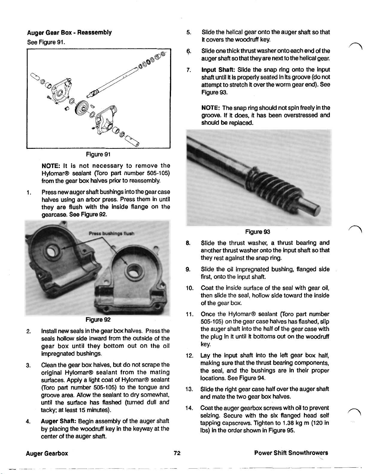
Auger Gear
See Figure 91.
Box
Reassembly
Slide the helical gear onto the auger shaft
5.
it
covers the woodruff key.
Slide one thick thrust washer onto each
6.
auger shaft
Input
7.
shaft until
attempt to stretch
Figure
so
that they are next to the helical gear.
Shaft:
Slide the snap ring onto the input
it
is properly seated in
it
over the worm gear end). See
93.
its
so
that
end
of
the
groove (do not
NOTE:
groove. If
should
Slide the thrust washer, a thrust bearing and
8.
another thrust washer onto the input shaft
they rest against the snap ring.
Slide the
9.
first, onto the input shaft.
The snap ring should not spin freely in the
it
does,
it
has been overstressed and
be
replaced.
93
Figure
oil
impregnated bushing, flanged side
so
that
Figure 92
Install new seals in the gear box halves. Press the
2.
seals hollow side inward from the outside of the
gear box until they bottom out on the oil
impregnated bushings.
Clean the gear box halves, but do not scrape the
3.
original HyIomar(R) sealant from the mating
surfaces. Apply a light coat of Hylomar(R) sealant
(Toro
part
number
groove area. Allow the sealant to dry somewhat,
until the surface has flashed (turned dull and
tacky: at least
Auger Shaft:
4.
by placing the woodruff key in the keyway at the
center of the auger shaft.
505-105)
15
minutes).
Begin assembly of the auger shaft
to the tongue and
Coat the inside surface of the seal with gear oil,
10.
then slide the seal, hollow side toward the inside
of the gear
Once the Hylomar(R) sealant Foro part number
11.
505-105) on the gear case halves has flashed, slip
the auger shaft into the half of the gear case with
the plug in
key.
Lay the input shaft into the left gear box half,
12.
making sure that the thrust bearing components,
the seal, and the bushings are in their proper
locations. See Figure
Slide the right gear case half over the auger shaft
13.
and mate the
Coat the auger gearbox screws with
14.
seizing. Secure with the six flanged head self
tapping capscrews. Tighten to
Ibs) in the order shown in Figure
box.
it
until
it
bottoms
two
gear box halves.
Power
94.
out
on the woodruff
oil
1.38
kg m
95.
Shift
Snowthrowers
to prevent
(120
in
Page 80
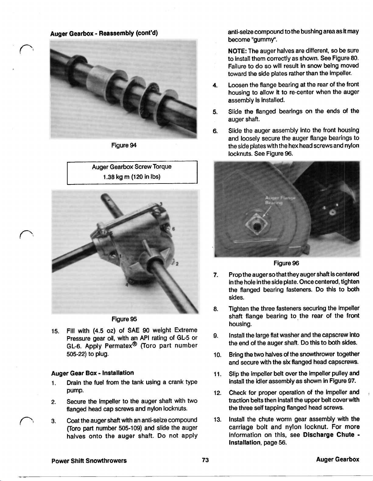
Auger Gearbox Reassembly (cont’d)
anti-seize compound to the bushing area as
become’ “gummy”.
it
may
Figure
Auger Gearbox Screw Torque
1.38 kg m (120 in
94
Ibs)
NOTE:
to install them correctly as shown. See Figure
Failure to do
toward the side plates rather than the impeller.
Loosen the flange bearing at
4.
housing to allow
assembly is installed.
Slide the flanged bearings on the ends of
5.
auger shaft.
Slide the auger assembly into the front housing
6.
and loosely secure the auger flange bearings to
the side plates with the hex head screwsand nylon
locknuts. See Figure
The auger halves are different,
so
will result in snow being moved
the
rear of the front
it
to re-center when the auger
96.
so
be
sure
80.
the
Figure
15. Fill with
Pressure gear oil, with an API rating of
GL-6.
505-22)
Auger Gear Box Installation
1.
Drain the fuel from the tank using a crank type
pump.
2. Secure the impeller to the auger shaft with
flanged head cap screws and nylon locknuts.
3.
Coat the auger shaft with an anti-seize compound
(Toro
halves onto the auger shaft. Do not apply
(4.5
oz) of
Apply Permatex(R) (Toro part number
to plug.
part
number
95
SAE
505-109)
90 weight Extreme
and slide the auger
GL-5
or
two
Figure
7.
Prop the auger
in the hole in the side plate. Once centered, tighten
the flanged bearing fasteners.
sides.
8. Tighten the three fasteners securing the impeller
shaft flange bearing to
housing.
9.
Install the large flat washer and the capscrew into
the end of the auger shaft.
10. Bring the
and secure with the
11.
Slip the impeller belt over the impeller pulley and
install the idler assembly as shown in Figure
12.
Check for proper operation of the impeller and
traction belts then install the upper belt cover with
the three self tapping flanged head screws.
13. Install the chute worm gear assembly with the
carriage bolt and nylon locknut. For more
information on this, see Discharge Chute
Installation, page
so
two
halves of the snowthrower together
96
that they auger shaft is centered
Do
this to both
the
rear of
Do
this to both sides.
six
flanged head capscrews.
56.
the
front
97.
Power Shift Snowthrowers
73
Auger Gearbox
Page 81
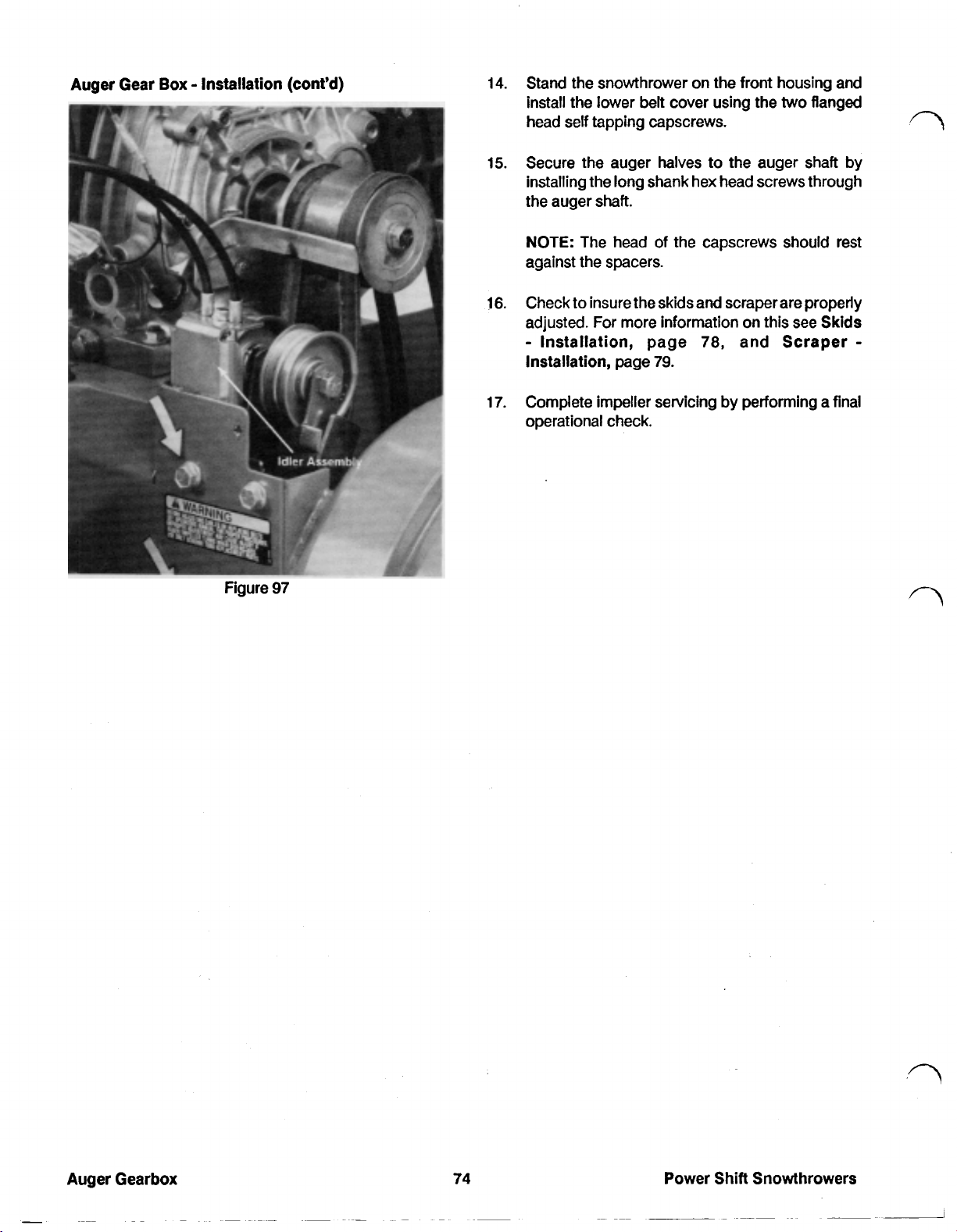
Auger Gear Box Installation (cont’d)
14.
Stand the snowthrower on the front housing and
install the lower belt cover using the
two
flanged
head self tapping capscrews.
Secure the auger halves to the auger shaft by
15.
installing the long shank hex head screws through
the auger
shaft.
NOTE: The head of the capscrews should rest
against the spacers.
Check to insure the skids and scraper are properly
16.
adjusted. For more information on this see Skids
Installation, page
Installation, page
17.
Complete impeller servicing by performing a final
79.
78,
and Scraper
operational check.
Figure
97
Power Shift Snowthrowers
Page 82
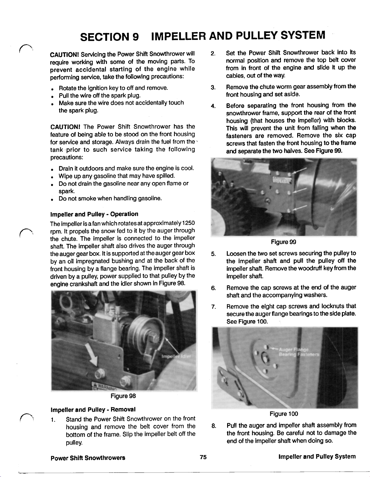
SECTION
CAUTION! Servicing the Power Shift Snowthrower will
require working with some of the moving parts. To
prevent accidental starting of the engine while
performing service, take the following precautions:
Rotate the ignition key to
Pull the wire
Make sure the wire does not accidentally touch
the spark plug.
CAUTION! The Power Shift Snowthrower has the
feature of being able to be stood on the front housing
for service and storage. Always drain the fuel from the
tank .prior to such service taking the following
precautions:
Drain
it
Wipe up any gasoline that may have spilled.
Do not drain the gasoline near any open flame or
spark.
Do
not smoke when handling gasoline.
off
the spark plug.
outdoors and make sure the engine is cool.
9
off
and remove.
IMPELLER
AND
2.
3.
4.
PULLEY
Set the Power Shift Snowthrower back into its
normal position and remove the top
from in front of the engine and slide
cables, out of the way.
Remove the chute worm gear assembly from the
front housing and set aside.
Before separating the front housing from the
snowthrower frame, support the rear of the front
housing (that houses the impeller) with blocks.
This will prevent the unit from falling when the
fasteners are removed. Remove the six cap
screws that fasten the front housing to the frame
and
separate the
SYSTEM
two
halves. See Figure
belt
it
99.
cover
up the
Impeller and Pulley Operation
The impeller is a fan which rotatesat approximately
rpm.
It
propels the snow fed to
the chute. The impeller
shaft. The impeller shaft also drives the auger through
the auger gear box.
by an oil impregnated bushing and at the back of the
front housing by a flange bearing. The impeller shaft is
driven by a pulley, power supplied to that pulley by
engine crankshaft and the idler shown in Figure
It
is supported at the auger gear box
it
by the auger through
is
connected to the impeller
1250
the
98.
Figure
99
Figure
Impeller and Pulley Removal
1.
Stand the Power Shift Snowthrower on the front
housing and remove the belt cover from the
bottom
pulley.
Power Shift Snowthrowers
of
the frame. Slip the impeller belt
98
off
the
75
Impeller and Pulley System
Page 83

Impeller and Pulley Removal (cont'd)
9. Remove the impeller from the Impeller shaft by
removing the
locknuts. Be careful not to lose the
hub inserts. (On
impeller to the
two
flanged cap screws and nylon
two
'88
units, set screws retained the
shaft.)
impeller
10. If impeller bearing servicing is necessary, remove
the flange bearing from the rear of the housing by
removing the three nylon locknuts.
1 1. Inspect all parts for damage and wear and replace
as necessary.
Impeller and Pulley Installation
1. If the impeller bearing was removed, reassemble
the bearing as shown in Figure 101. Note that the
flanged portion of the oil impregnated bearing
faces forward.
The entire flange bearing must fit behind the front
housing.
Also
notice the the hollow head set screw
faces up when correctly installed.
3.
Prepare for impeller installation by making sure
that the inserts are in place on the impeller hub
and by coating the impeller shaft with an anti-seize
compound (Toro part number 505-109). Fasten
the impeller to the impeller shaft with the
flanged cap screws
screws were used on
NOTE:
When the flanged head cap screws are
and
nylon locknuts. (Set
'88
product.)
two
installed correctly, the heads will be against the
inserts.
4.
Slide the impeller into the front housing making
sure that the bearings at the end of the auger shaft
have not fallen
Installation,
off.
page
If
they have, consult Auger
70,
for information on how to
reassemble.
Secure the auger shaft bearings to the side plates
using the eight cap screws and nylon locknuts.
See Figure
103.
I
Figure 101
2. Loosely fasten the flange bearing to the rear of the
front housing using Figure 102 as a guide.
I
Figure 102
NOTE:
ween the components of the flange bearing.
Do
not sandwich the front housing bet-
Figure 103
Install the cap screws and large washers
5.
ends of the auger shaft.
Lightly tighten the hollow head set screw in the
6.
impeller shaft bearing.
Tighten the three nylon locknuts securing the
7.
impeller flange bearing to the front housing.
Coat the impeller shaft with an anti-seize
9.
compound (Toro part number
505-109)
the woodruf key and the impeller pulley. Be sure
to tighten both square head set screws. Remove
all end play from impeller shaft but
NOTE:
3/8”,
Tighten the square head set screws with a
12 pt. socket.
do
not preload.
Set Screw Torque:
2.3
kg m (205 in Ibs)
0
n
the
and install
Impeller and Pulley System
76
Power
Shift
Snowthrowers
Page 84
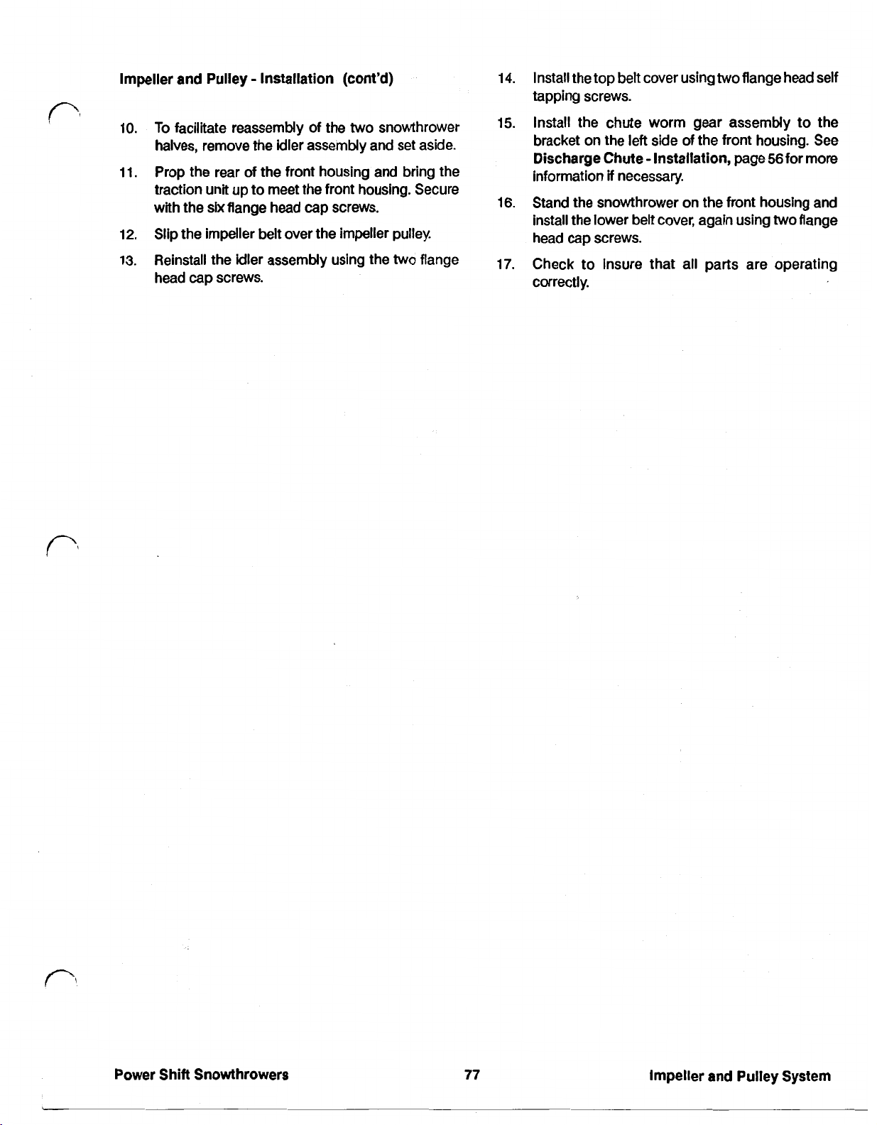
Impeller and Pulley Installation (cont’d)
10.
To
facilitate reassembly of the
two
snowthrower
halves, remove the idler assembly and set aside.
11.
Prop the rear of the front housing and bring the
traction unit up to meet the front housing. Secure
with the
12.
Slip the impeller belt over the impeller pulley.
13.
Reinstall the idler assembly using the
six
flange head cap screws.
two
head cap screws.
flange
14.
Install the top
belt
cover using
two
flange head self
tapping screws.
15.
Install the chute worm gear assembly to the
bracket on the left side of the front housing. See
Discharge Chute Installation, page 56 for more
information
16. Stand the snowthrower
install the lower belt cover, again using
if
necessary.
on
the front housing and
two
head cap screws.
17.
Check to insure that all parts are operating
correctly.
flange
Power Shift Snowthrowers
77
Impeller and Pulley System
Page 85

SECTION
CAUTION! Servicing the Power
require working with some of the moving parts.
prevent accidental starting of the engine while
performing service, take the following precautions:
Rotate the ignition key to
Pull the wire
Make sure the wire does not accidentally touch
the spark plug.
off
the spark plug.
Shift
off
and remove. pages
Snowthrower will
10
To
FRONT
3.
Install the chute assembly as described under
Discharge Chute Installation, page
4.
Adjust
Skids Installation and Scraper Installation,
SKIDS
HOUSING
the scraper
78
and
and
79
skids
as
described
56.
under
CAUTION! The Power Shift Snowthrower has the
feature
for Service and Storage. Always drain the fuel from the
tank Prior to such Service taking the following
precautions:
FRONT HOUSING
Front Housing Operation
The front housing is very durable and should rarely
require servicing, however
the following procedure.
1.
2.
3.
Of
being able to be Stood on the front housing
Drain
it
outdoors and make sure the engine is cool.
Wipe up any gasoline that may have spilled.
Do not drain the gasoline near any open flame or
spark. to the pavement.
Do not smoke when handling gasoline.
if
the damage occurs, use
Remove the chute assembly as described under
Discharge Chute Removal, page
Remove the impeller and auger assembly as
described under Impeller
Removal, page
Remove the scraper as described under Scraper
Removal, page
75.
79.
and
56.
Pulley System
Skids Operation
The purpose of the skids is to provide more contact area
with the ground. When properly adjusted, they slow
wearing
wearing
For convenience, the skids are turned inward to allow
cleaning along side obstacles. The skids are adjustable
to help insure that the snowthrower cleans right down
Skids Removal
1.
Remove the skids by removing the
cap screws securing them to the side plates.
2.
Inspect the skids. Replace when the outside edge
of the skid begins wearing away.
Skids Installation
1.
With the wheels in the rear position, loosen the
lock nut on the skid support bracket to insure that
it
gets proper placement when the new skid is put
on.
2.
Install the skid as shown in Figure
of
the scraper. The skids are intended to be a
part.
two
flanged
104.
4.
Inspect for damage and repair or replace the
housing as necessary.
Front Housing Installation
1.
If
the front housing was replaced or painted be
sure that all safety decals are also replaced and
are in the proper location.
2.
Install the impeller and auger assembly as
described under Impeller and Pulley System
Installation, page
76.
78
Figure
104
Power Shift Snowthrowers
Page 86

Skids Installation (cont'd)
skid
NOTE: The pads of the
3.
Adjust the skids
(1/8'”)
clearance between the scraper and the
so
that the scraper has
are turned inboard.
3
ground. Make sure that the pad is riding flat. Adjust
higher
if
operating on a crushed rock or gravel
surface.
SCRAPER
Scraper Operation
The scraper on
1989
and newer Power Shifts is
adjustable. This is to insure that snow is removed as
close to the ground as possible.
Scraper Removal
See Figure
105.
mm
3.
Inspect the scraper. Replace when
within
.64
cm
(1/4”)
from the bottom of the front
the
scraper is
housing and has been adjusted as low as
Scraper Installation
1.
Begin scraper installation by first checking tire
pressure in both tires. Make sure that they are both
equal
and
psi).
Also
sitting on
between
make sure that the snowthrower is
a
level surface. This will insure proper
.5
and
1.O
kg/cm2
(7
positioning of the scraper.
2.
Loosen the
skid
mounting screws
so
that the skids
are free to move and will not interfere with scraper
adjustment.
3.
install the front flanged cap screw, securing the
scraper, side plate and the skid
4.
On a flat surface with the snowthrower
on
each side.
normal operating position, support the auger
is
.32
cm
(1/8'”)
off
the ground.
5.
Move the scraper
so
that
it
contacts the flat
surface all the way across, then tighten the
flanged cap screws securing
side plate. This locks
the remainder of
the
it
and the skids to the
it
in proper position
fasteners can be installed
without affecting adjustment.
it
will go.
and
in
so
15
the
so
it
two
that
Figure
1.
Remove the
2.
Remove the front flanged cap screw from the skid
and
remove the scraper.
six
carriage bolts from the scraper.
105
6.
Push the handles down
so
that the snowthrower
rests on the handles and secure the scraper with
the six carriage bolts and nylon locknuts.
7.
Adjust the skids with the scraper in the new
position as described under Skids Installation,
page
78.
Power Shift Snowthrowers
79
Front Housing
Page 87
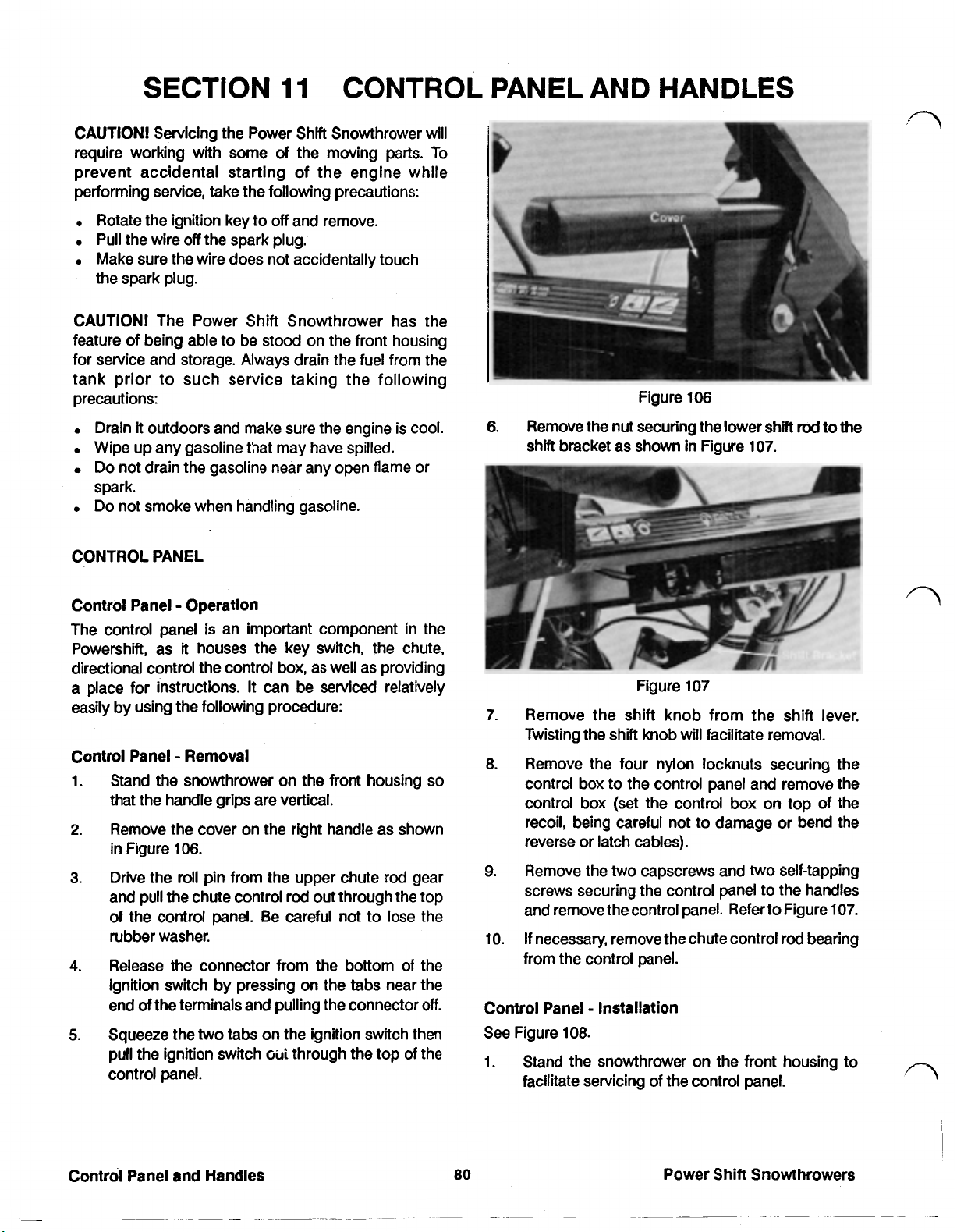
SECTION
CAUTION! Servicing the Power Shift Snowthrower will
require working with some of the moving parts. To
prevent accidental starting of the engine while
performing service, take the following precautions:
11
CONTROL PANEL AND HANDLES
Rotate the ignition key to
Pull the wire
Make sure the wire does not accidentally touch
the spark plug.
CAUTION! The Power Shift Snowthrower has the
feature of being able to be stood on the front housing
for service and storage. Always drain the fuel from the
tank prior to such service taking the following
precautions:
Drain it outdoors and make sure the engine is cool.
Wipe
up
Do not drain the gasoline near any open flame or
spark.
Do not smoke when handling gasoline.
CONTROL PANEL
Control Panel Operation
The control panel is an important component in the
Powershift, as
directional control the control box, as well as providing
a place for instructions.
easily by using the following procedure:
Control Panel Removal
Stand the snowthrower on the front housing
1.
that the handle grips are vertical.
Remove the cover on
2.
in Figure
Drive the
3.
and pull
of the control panel. Be careful not to lose the
rubber washer.
Release the connector from the bottom of the
4.
ignition switch by pressing on the tabs near the
end of the terminals and pulling the connector
Squeeze the
5.
pull the ignition switch
control panel.
off
the spark plug.
any gasoline that may have spilled.
it
houses the key switch, the chute,
106.
roll
pin from the upper chute rod gear
the
chute control
two
off
and remove.
It
can
be
serviced relatively
so
the
right handle as shown
rod
out through the top
off.
tabs on the ignition switch then
out
through the top of the
Figure
6.
Remove the nut securing the lower shift
shift
bracket as shown
Figure
7.
Remove the shift knob from the shift lever.
Twisting the shift knob will facilitate removal.
8.
Remove the four nylon locknuts securing the
control box to the control panel and remove the
control box (set the control box on top of the
recoil, being careful not to damage
reverse
9.
Remove the
screws securing the control panel to the handles
and remove the control panel. Refer to Figure
10.
If
from the control panel.
Control Panel Installation
See Figure
Stand the snowthrower on the front housing to
1.
facilitate servicing of the control panel.
or
latch cables).
two
necessary, remove the chute control
108.
106
in
Figure
107
capscrews and
107.
two
rod
to the
or
bend the
self-tapping
107.
rod
bearing
Control Panel and Handles
80
Power Shift Snowthrowers
Page 88
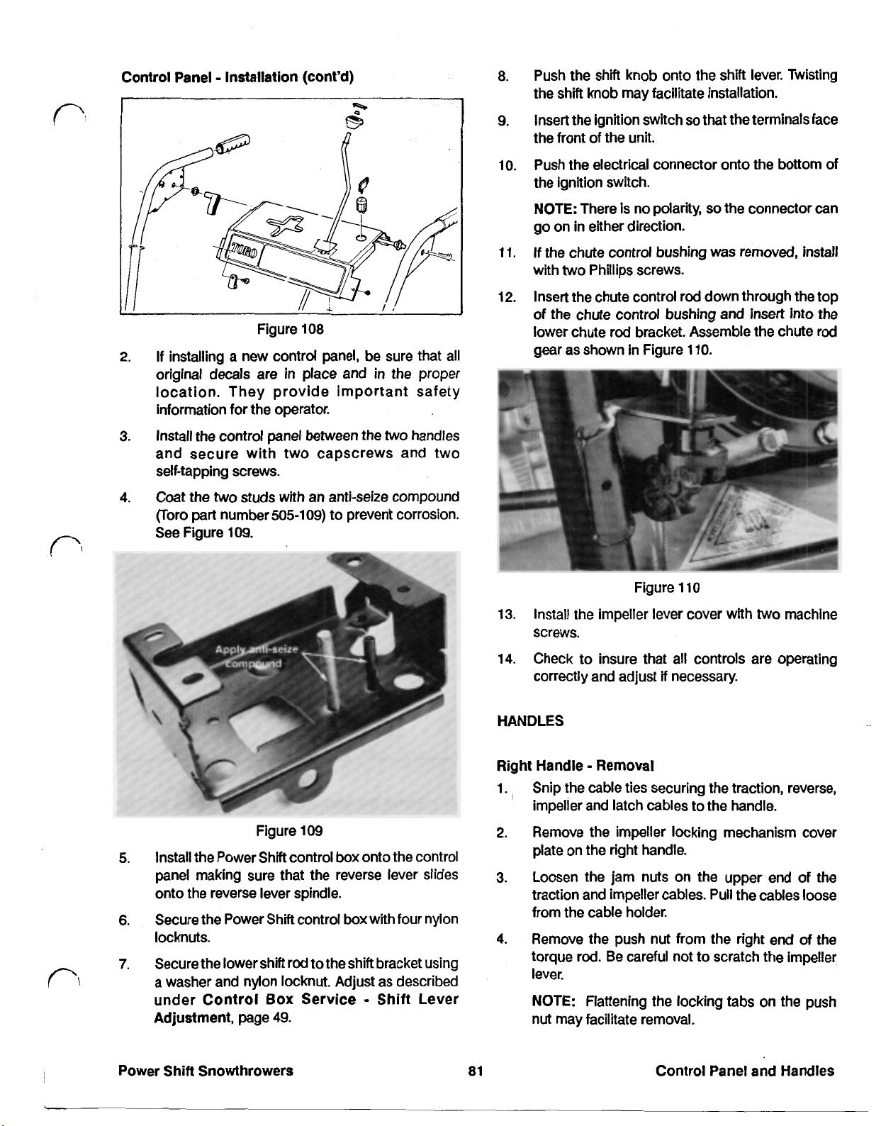
Control Panel Installation (cont'd)
8.
Push the shift knob onto the
the shift knob may facilitate installation.
9.
Insert the ignition switch
the front of the unit.
10.
Push the electrical connector onto the bottom of
the ignition switch.
shift
so
that the terminalsface
lever. Twisting
Figure
2.
If installing a new control panel, be sure that all
original decals are in place and
location. They provide important safety
information for the operator.
3.
Install the control panel between the
and secure with two capscrews and two
self-tapping screws.
4.
Coat the two studs with an anti-seize compound
(Toro part number
See Figure
109.
108
505-109)
in
to prevent corrosion.
the
two
proper
handles
NOTE:
go on in either direction.
11.
If
with
12.
Insert the chute control rod down through
of
lower chute rod bracket. Assemble the chute
gear as shown in Figure
13.
Install the impeller lever cover with
screws.
There is no polarity,
the
chute control bushing was removed, install
two
Phillips screws.
the chute control bushing
Figure
so
110.
110
the connector can
the
top
and
insert into the
rod
two
machine
Figure
5.
Install the Power Shift control box onto the control
panel making sure that the reverse lever slides
onto the reverse lever spindle.
6.
Secure the Power Shift control box with four nylon
locknuts.
7.
Secure the lower shift rod to the shift bracket using
a washer and nylon locknut. Adjust as described
under Control
Adjustment, page
Box
49.
109
Service
Shift
Lever
14.
Check to insure that all controls are operating
if
correctly and adjust
HANDLES
Right Handle Removal
1.
Snip
the
cable ties securing the traction, reverse,
impeller and latch cables to the handle.
2.
Remove the impeller locking mechanism cover
plate on the right handle.
3.
Loosen the jam nuts on the upper end of the
traction and impeller cables.
from the cable holder.
4.
Remove the push nut from the right end of the
torque rod. Be careful not to scratch the impeller
lever.
NOTE:
nut may facilitate removal.
Flattening the locking tabs
necessary.
Pull
the cables loose
on
the push
Power Shift Snowthrowers
81
Control Panel and Handles
Page 89
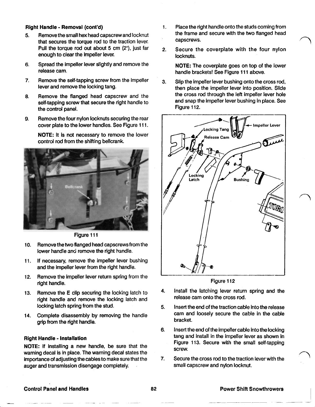
Right Handle
5.
Remove the
Removal
small
hex head capscrew and locknut
(cont'd)
that secures the torque rod to the traction lever.
Pull the torque rod out about
enough to clear
6.
Spread the impeller lever slightly and remove the
the
impeller lever.
5
cm
release cam.
7.
Remove the self-tapping screw from the impeller
lever and remove the locking tang.
8.
Remove the flanged head capscrew and the
self-tapping screw that secure the right handle
the control panel.
9.
Remove the four nylon locknuts securing the rear
cover plate to the lower handles. See Figure
(2”),
just far
111.
to
1.
Place the right handle onto the studs coming from
the frame and secure with the
two
flanged head
capscrews.
2.
Secure the coverplate with the four nylon
locknuts.
NOTE:
handle brackets! See Figure
3.
Slip the impeller lever bushing onto the cross rod,
The coverplate goes on top of the lower
111
above.
then place the impeller lever into position. Slide
the cross rod through the
left
impeller lever hole
and snap the impeller lever bushing in place.
Figure
112.
See
NOTE:
control rod
10.
Remove the
lower handle
11.
If
It
is not necessary to remove the lower
from
the shifting bellcrank.
Figure
two
flanged head capscrews from the
and
111
remove the right handle.
necessary, remove the impeller lever bushing
and the impeller lever from the right handle.
12.
Remove the impeller lever return spring from the
right handle.
13.
Remove the E clip securing the locking latch to
right handle and remove the locking latch and
locking latch spring from the stud.
14.
Complete disassembly by removing the handle
grip from the right handle.
Right
Handle Installation
NOTE:
If installing a new handle, be sure that the
warning decal is in place. The warning decal states the
importance of adjusting the cables to make sure that the
auger and transmission disengage completely.
Figure
4.
Install the latching lever return spring and the
112
release cam onto the cross rod.
Insert the end of the traction cable into the release
5.
cam and loosely secure the cable
in
the cable
bracket.
Insert the end of the impeller cable into the locking
6.
tang and install in the impeller lever as shown in
Figure
113.
Secure with the small self-tapping
screw.
7.
Secure the cross rod to the traction lever with the
small capscrew and nylon locknut.
82
Power Shift Snowthrowers
Page 90

Right Handle Installation (cont'd)
6.
Remove the small hex head capscrews and nylon
locknuts securing the cross rod to the traction
lever.
Figure
Press the push nut onto the end of the cross rod
8.
113
to secure the impeller lever.
NOTE: Make sure the tab on the push nut is at
to the keyway to insure proper retention
Secure the control panel to the handle using the
9.
flanged head capscrew and self-tapping screw.
If the locking latch and the locking latch spring
10.
were removed, install now. Secure with the
Refer to Figure
Secure the cables with
11.
Adjust the impeller and traction cables as
12.
113
above.
two
cable ties.
described under Traction and Impeller Controls
Traction Cable Adjustment and Traction and
Impeller Controls Impeller Cable Adjustment,
page
49.
Install the cover plate on the right handle
with the
Complete handle replacement by checking all
13.
two
small machine screws.
controls and making adjustments as required.
E
90"
clip.
7.
Pull the cross rod from
Figure
114
the
impeller lever control
panel and traction lever.
NOTE: The release cam, impeller bushing, trip
lever and traction lever spacer will all be
once the cross rod is removed. Be careful not to
loose them.
8.
Remove the flanged head capscrew and small
self-tapping screw securing the
control panel. See Figure
115.
left
handle to the
loose
Left Handle Removal
1.
Stand the snowthrower on the front housing to
facilitate handle removal.
2.
Snip the cable ties securing the wiring harness to
the left handle.
3.
Drive out the roll pin securing the upper chute
directional gear to the upper chute control rod.
Remove the gear and the rubber washer, then pull
the upper chute rod from the control panel.
4.
Remove the impeller locking mechanism cover
from the right handle.
5.
Remove the push nut securing the impeller lever
to the cross rod. Refer to Figure
114.
NOTE: Flattening the locking tabs on the push nut
may facilitate removal.
Power Shift Snowthrowers
83
Figure
9.
Remove the four nylon locknuts securing the rear
115
cover plate to the lower handle brackets and the
rear cover plate.
10.
Remove the two flanged head capscrews
securing the lower handle to the frame and
remove the left handle complete with the front
chute control rod.
Control Panel and Handles
Page 91

Left Handle Removal (cont’d)
11.
If necessary, drive the roll pin from the forward
chute control rod and gear and remove the chute
control rod from the right angle bracket.
12.
Complete disassembly by removing the handle
grip from the left hand handle.
Place the chute worm gear into the worm gear
3.
bracket then place the left handle onto the studs
while inserting the lower control rod into the chute
worm gear.
Move the rear cover plate into position on the four
4.
studs and secure with four nylon locknuts.
Left Handle Installation
See Figure
116.
Traction
Lever
NOTE:
The rear cover plate
fits
outside the handle
bracket.
5.
7.
Install the
the
Secure the
two
flanged head capscrews securing
left
handle to the frame.
left
handle to the control panel using
the self-tapping screw and the flanged head
capscrew.
Insert the upper chute control rod through the
8.
control panel and the right angle bracket while
installing the rubber washer and the upper chute
directional gear. Secure with the roll pin.
Place the traction lever into position on the left
9.
handle and loosely fasten in placewith the traction
lever bushing.
Place the traction lever spacer inside the traction
10.
lever then slip the cross
rod
through the trip lever.
Make sure that the traction and impeller cables are
installed into the release cam and locking latch
then push the cross rod through both
components. Secure with
a
new push nut.
1.
Stand
Figure
the
Power Shift Snowthrower onto the front
116
housing to facilitate installation.
2.
Insert the lower chute control rod into the right
angle bracket and secure the gear with the roll pin.
NOTE:
Install the locking latch cover plate on the right
11.
hand handle using the
The release cam is keyed to the cross rod.
two
small machine screws
with star washers.
Secure the
12.
left
end of the cross rod to the traction
lever with the small capscrew and nylon locknut.
Secure the ignition switch wire to the
13.
with
two
cable ties.
14.
Complete handle replacement by checking all
left
controls and making adjustments as required.
handle
Control Panel and Handles
Power Shift Snowthrowers
Page 92
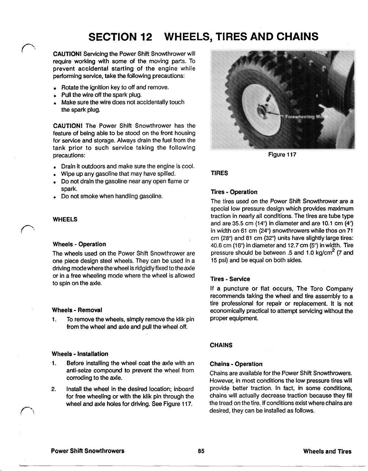
SECTION
CAUTION! Servicing the Power Shift Snowthrower will
require working with some
prevent accidental starting of the engine
performing service, take the following precautions:
12
of
the moving parts. To
WHEELS,
while
TIRES
AND CHAINS
Rotate the ignition key to
Pull the wire
Make sure the wire does not accidentally touch
the spark plug.
CAUTION! The Power Shift Snowthrower has the
feature of being able to be stood on the front housing
for service and storage. Always drain the fuel from the
tank prior to such service taking the following
precautions:
Drain
Wipe up any gasoline that may have spilled.
Do not drain the gasoline near any open flame or
spark.
Do not smoke when handling gasoline.
WHEELS
Wheels Operation
The wheels used on the Power Shift Snowthrower are
one piece design steel wheels. They can
driving modewhere the wheel is rigidly fixed to the axle
or in a free wheeling mode where the wheel is allowed
to spin on the axle.
Wheels Removal
1.
To remove the wheels, simply remove the klik pin
from the wheel and axle and pull the wheel
off
the spark plug.
it
outdoors and make sure the engine is cool.
off
and remove.
be
used in a
off.
Figure
TIRES
Tires Operation
The tires used on the Power Shift Snowthrower are
special low pressure design which provides maximum
traction in nearly all conditions. The tires are tube type
and are 35.5 cm (14') in diameter and are 10.1 cm
in width on
cm (28”) and 81 cm (32") units have slightly large tires:
40.6
pressure should be between
15 psi) and be equal on both sides.
Tires
If a puncture or flat occurs, The Toro Company
recommends taking the wheel and tire assembly
tire professional for repair or replacement.
economically practical
proper equipment.
cm
(16')
Service
61
cm
(24")
in diameter and 12.7 cm
117
(4")
snowthrowers while thos on 71
(5")
in
width. Tire
.5
and 1.0 kg/cm2
(7
and
to
It
is not
to
attempt servicing without the
a
a
Wheels Installation
1. Before installing the wheel coat the axle with an
anti-seize compound
corroding
2. Install the wheel in the desired location; inboard
for free wheeling or with the klik pin through the
wheel and axle holes for
Power Shift Snowthrowers
to
the axle.
to
prevent the wheel from
driving.
See Figure 117.
CHAINS
Chains Operation
Chains are available for the Power Shift Snowthrowers.
However, in most conditions the low pressure tires will
provide better traction.
chains will actually decrease traction because they fill
the tread on the tire. If conditions exist where chains are
desired, they can be installed as follows.
85
In
fact,
in
some conditions,
Wheels and Tires
Page 93
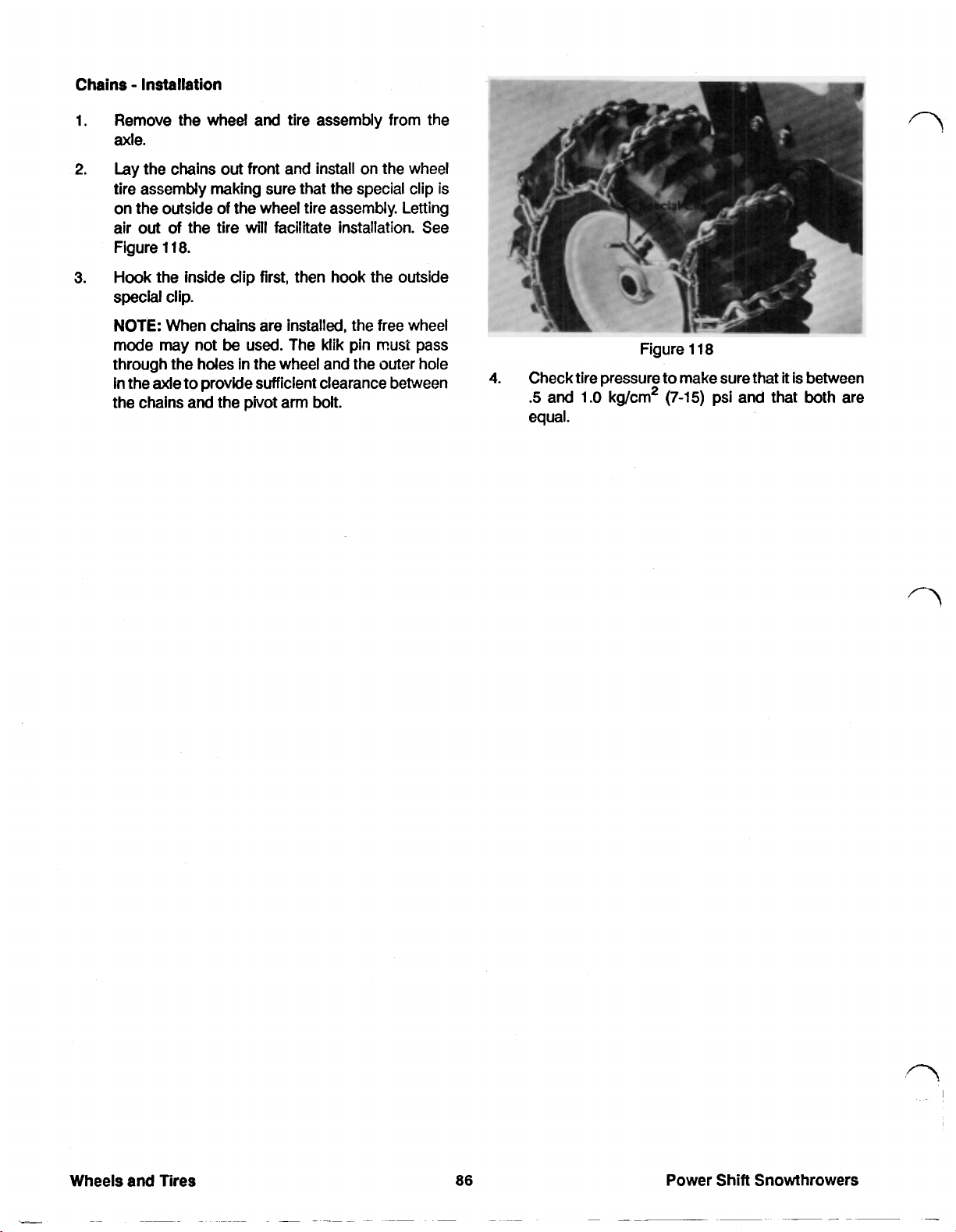
Chains Installation
Remove the wheel and tire assembly from the
1.
rude.
Lay the chains out front and install on the wheel
2.
tire assembly making sure that the special clip is
on the outside
air
out
of
Figure
Hook the inside clip first, then hook the outside
3.
118.
of
the wheel tire assembly. Letting
the tire
will
facilitate installation. See
special clip.
NOTE: When chains are installed, the free wheel
mode may not
through the holes in
used. The klik pin
the
wheel and the outer hole
must
be
in the axle to provide sufficient clearance between
the chains and the pivot arm bolt.
pass
Figure
4.
Check tire pressure to make sure that
.5
and
1.O
kg/cm2
118
(7-15)
equal.
it
is between
psi and that both are
Power Shift Snowthrowers
Page 94

SECTION
13
Engines Service Information
A
number of different engines are
used
on the Power
Shift Snowthrowers. Manufacturer. include Briggs and
Stratton, Mitsubishi and Tecumseh. See Figure
119
below to determine the manufacturer of the engine on
the unit you are servicing.
SPECIFICATIONS
Name Manufacturer
624
624
624
624
824
824
824
824
828
1132
828
828
1132
Engine
Mitsubishi
Mitsubishi
Tecumseh
Tecumseh
Mitsubishi
Mitsubishi
Tecumseh
Tecumseh
Mitsubishi
Briggs
Briggs
8
Tecumseh
Briggs
8
Figure
8
Stratton
Stratton
Stratton
119
Sold
In
U.S.
Int'l
U.S.
Int'l
us.
Int'l
us.
Int'l
Int'l
Int'l
U.S.
Int'l
us.
Some information on specifications and maintenance of
the engines can be found in the Specifications and
Maintenance Sections
in
the front of the book.
However, because the engine manufacturers have each
published their own manual for these engines, complete
servicing information is not included in this
If
you
require a manual for one of the engines please
book.
contact the engine manufacture at one the following
addresses:
Briggs and Stratton
PO.
Box
702
Milwaukee, WI
53201
Mitsubishi Heavy Industries America, Inc.
699
North Wheeling
Suite
101
Mount Prospect,
IL
Road
60056
Tecumseh Products Company
900
North Street
Grafton, WI
53024
Be sure to include engine model and serial number with
your request.
If
you have difficulty obtaining engine service manuals
from any of the above manufacturers, please feel free to
contact
us
at the following address:
The Toro Company
8111
Lyndale Avenue South
Bloomington,
MN
55420
Power
Shift
Snowthrowers
a7
Engines
Page 95
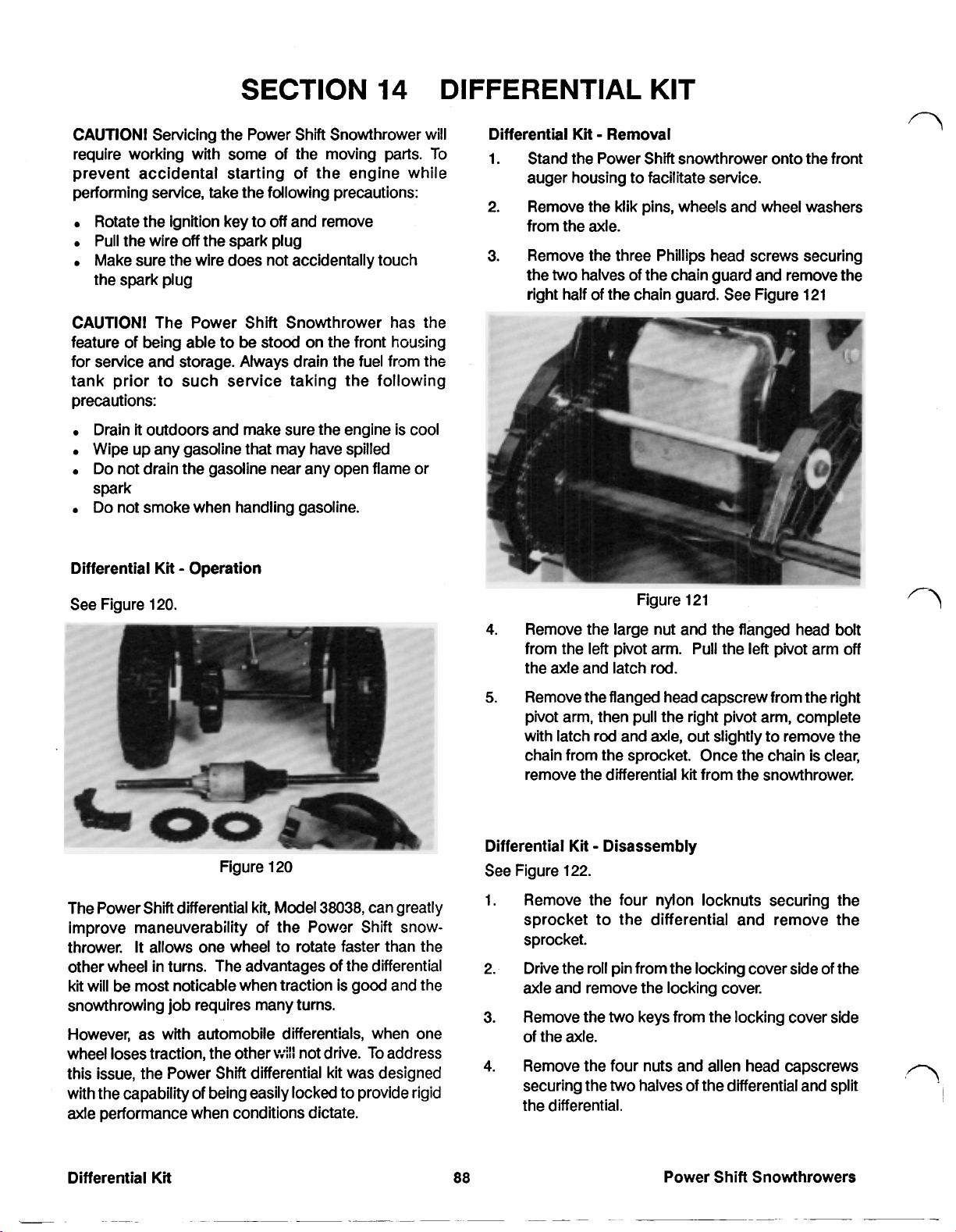
SECTION
14
DIFFERENTIAL
KIT
CAUTION!
require working with some of the moving parts.
prevent accidental starting of the engine while
performing service, take the following precautions:
Rotate the ignition key to
Pull the wire
Make sure the wire does not accidentally touch
the spark plug
CAUTION!
feature of being able to be stood on the front housing
for service and storage. Always drain the fuel from the
tank prior to such service taking the following
precautions:
Drain
Wipe up any gasoline that may have spilled
Do not drain the gasoline near any open flame or
spark
Do not smoke when handling gasoline.
Differential
Servicing the Power Shift Snowthrower will
off
and remove
off
the spark plug
The Power Shift Snowthrower has the
it
outdoors and make sure the engine is cool
Kit
Operation
To
Differential
1. Stand the Power Shift snowthrower onto the front
2. Remove
3.
Kit
Removal
auger housing to facilitate service.
the
klik pins, wheels and wheel washers
from the axle.
Remove the three Phillips head screws securing
the
two
halves of the chain guard and remove the
right half of the chain guard. See Figure 121
See Figure 120.
Figure 120 See Figure 122.
kit,
Model
The Power Shift differential
improve maneuverability of the Power Shift snowthrower.
other wheel in turns. The advantages of the differential
kit
will be most noticable when traction is good and the
snowthrowing job requires many turns.
However, as with automobile differentials, when one
wheel loses traction, the other
this issue, the Power Shift differential kit was designed
with the capability of being easily locked to provide rigid
axle performance when conditions dictate.
It
allows one wheel to rotate faster than the
38038,
will
not drive. To address
can greatly
Figure 121
4.
Remove the large nut and the flanged head bolt
left
from the left pivot arm. Pull the
the axle and latch rod.
5.
Remove the flanged head capscrew from the right
pivot arm, then pull the right pivot arm, complete
with latch rod and axle, out slightly to remove the
chain from the sprocket. Once the chain is clear,
remove the differential
Differential Kit Disassembly
1. Remove the four nylon locknuts securing the
sprocket to the differential and remove the
sprocket.
2. Drive the roll pin from the locking cover side
axle and remove the locking cover.
3.
Remove the
of the axle.
4.
Remove the four nuts and allen head capscrews
securing the
the differential.
two
two
kit
from the snowthrower.
keys from the locking cover side
halves of the differential and split
pivot arm
of
off
the
Differential
Kit
88
Power Shift Snowthrowers
Page 96

Differential
Locking
5.
Kt
Disassembly (cont’d)
Cover
Figure
122
Remove the cross shaft and the two cross shaft
gears from the differential.
6.
If
further disassembly is required, remove the snap
rings securing the bevel gears to the axle and
remove the gears and differential case halves from
the axles.
4.
Install
the
two
keys into the keyways on the long
axle shaft, then slide the locking cover onto the
it
shaft making sure that
moves freely over the
keys.
5.
Drive the roll pin into the locking cover half of the
axle.
6.
Mount the sprocket onto the differential and
secure with four nylon lock nuts.
Kt
Differential
1.
Stand the Power Shift snowthrower onto the front
Installation
housing to facilitate installation.
2.
If
the differential
kt
is being installed for the first
time, select the correct sprocket for the
differential. Use the list in Figure
123
or match the
number of teeth on the original sprocket with one
in the
kt.
Differential
Kt
Sprocket Data
7.
Inspect the spindle and the four gears for wear.
8.
Inspect the differential case halves for wear by
placing the case halves on the axle and checking
for excessive play. Excessive play indicates that
the bushings are worn. If this occurs, replace the
differential case halves.
Differential
Refer to Figure
1.
Kt
Assembly
122
above.
Place a bevel gear in one of the case halves and
secure to one of the axles with the snap ring.
Repeat for the other axle and case half.
NOTE:
Although there is a male and female
differential case half, they are otherwise
symmetrical and can be placed on either axle half.
2.
Spread Bentonite@ grease, (available from
Tecumseh/Peerless), onto
the
bevel gears, and
the cross shaft then slide the cross shaft pinions
onto the cross shaft.
3.
Install the cross shaft and cross shaft pinion
assembly into a differential case half and
assembly the case halves.
NOTE:
Make sure there is adequate lubricant, but
do not overfill.
3.
Slide a thrust washer onto each end of the axle.
4.
Slide the axle through the pivot arm and attach
chain. Fasten the right hand pivot arm to
frame, being sure to install the special washer
between the pivot arm and frame. Tighten the
flanged head pivot bolt and the nylon locknut. See
Figure
5.
If
in the differential
124.
necessary, install the new chain guard included
kt
onto the
left
hand pivot arm
with the two self-tapping capscrews.
the
the
Power Shift Snowthrowers
89
Differential
Kt
Page 97

Differential
Kit
Installation (cont'd)
7.
Install the right hand half
of
the chain guard with
the three Phillips screws.
Slide the thrust washers then the wheels onto
8.
each end of the
If
9.
this is the first time the differential
axle.
Secure with klik pins.
installed and the product was produced in
install the new belt cover as shown in Figure 125.
This belt cover provides clearance for the
differential when the wheels are in the forward
position.
kt
is
being
'88,
Figure 124
6.
Slide the thick washer onto the latch rod then
install the
the
frame. Secure the
flanged head capscrew
left
pivot arm, again being sure to install
special washer between the pivot arm and the
left
hand pivot arm with the
and
the nylon locknut.
Figure 125
10.
Check for proper operation of all controls and
adjust
if
necessary.
90
Power Shift Snowthrowers
Page 98
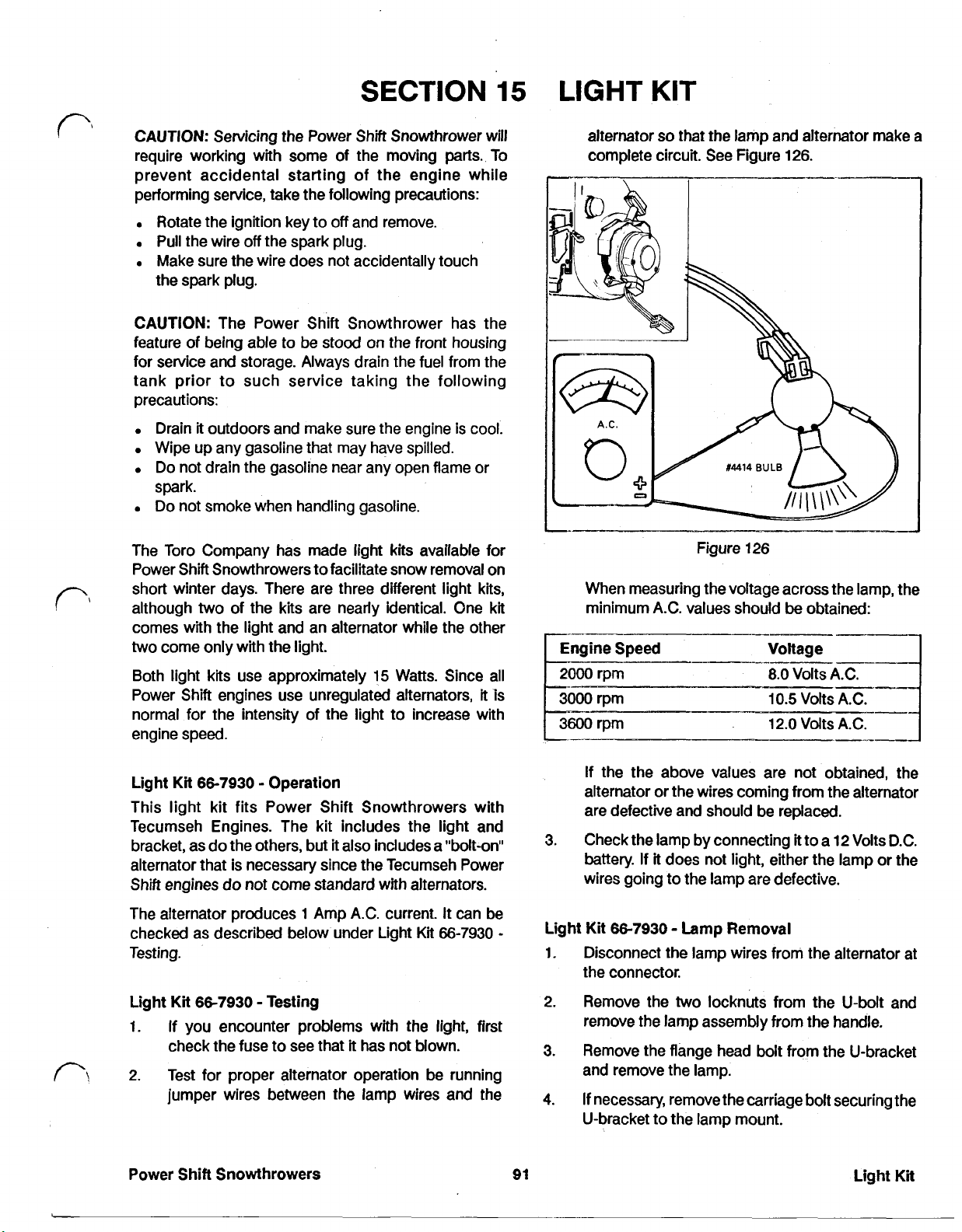
SECTION
15
LIGHT
KIT
CAUTION:
require working with some of the moving parts. To
prevent accidental starting of the engine while
performing service, take the following precautions:
Rotate the ignition key to
Pull the wire
Make sure the wire does not accidentally touch
the spark plug.
CAUTION:
feature of being able to be stood on the front housing
for service and storage. Always drain the fuel from the
tank prior to such service taking the following
precautions:
Drain
Wipe up any gasoline that may have spilled.
Do not drain the gasoline near any open flame or
spark.
Do
The Toro Company has made light
Power Shift Snowthrowers to facilitate snow removal on
short winter days. There are three different light
although two of the
comes with the light and an alternator while the other
two come only with the light.
Both light
Power Shift engines use unregulated alternators, it is
normal for the intensity of the light to increase with
engine speed.
Servicing the Power Shift Snowthrower will
off
and remove.
off
the spark plug.
The Power Shift Snowthrower has the
it
outdoors and make sure the engine
not smoke when handling gasoline.
kits
available for
kits
are nearly identical. One kit
kits
use approximately 15 Watts. Since all
is
cool.
kits,
alternator
complete circuit. See Figure 126.
When measuring the voltage across the lamp, the
minimum A.C. values should
2000 rpm
3600
rpm 12.0 volts A.C.
so
that the lamp and alternator make a
Figure 126
be
obtained:
Voltage
8.0
Volts A.C.
10.5 Volts A.C.
Light
Kit 66-7930
This light kit fits Power Shift Snowthrowers with
Tecumseh Engines. The kit includes the light and
bracket, as do the others, but
alternator that is necessary since the Tecumseh Power
Shift engines do not come standard with alternators.
The alternator produces 1 Amp A.C. current. It can be
checked as described below under Light
Testing.
Kit 66-7930
Light
1. If you encounter problems with the light,
check the fuse to see that
2. Test
Power Shift Snowthrowers
for
jumper wires between the lamp wires and the
Operation
it
also includes a "bolt-on"
Testing
it
has not blown.
proper alternator operation be running
Kt
66-7930
first
If the the above values are not obtained, the
alternator or the wires coming from the alternator
are defective and should be replaced.
3.
Check the lamp by connecting
battery. If it does not light, either the lamp or the
wires going to the lamp are defective.
Light
Kit
66-7930
1. Disconnect the lamp wires from the alternator at
the connector.
2.
Remove the two locknuts from the U-bolt and
remove the lamp assembly from the handle.
3.
Remove the flange head
and remove the lamp.
4.
If
necessary, remove the carriage bolt securing the
U-bracket to the lamp mount.
91
Lamp Removal
it
to a 12 Volts D.C.
bolt
from the U-bracket
Light
Kit
Page 99

Light
Kit
66-7930
1.
Using the U-bolt, washers and nuts supplied in
Lamp
Installation
loosely secure the lamp mount to
shown in Figure
127.
the
kit,
handle as
6.
Remove the alternator shaft.
Kit
Light
1.
2.
66-9730
Remove the recoil
If the recoil assembly has a center plug
housing, push
Figure
128.
Alternator Installation
it
out and proceed to step
If
not
so
if
still on the unit.
equipped, refer to step
4.
in
3.
the
See
Figure
Route the wires and the fuse holder inside the
2.
127
channel and through the U-bolt.
3.
Secure the U-bracket to the lamp mount with a
carriage bolt, lock washer and nut. Do not
overtighten the nut or lamp adjustment will be
difficult.
4.
Secure the lamp assembly to the U-bracket with
two
a flange head screw,
lock washers and a
flange nut. Place a washer on each side between
the U-bracket and the lamp bracket. Do not
overtighten.
Light Kit
1.
66-7930
Snip the
Alternator Removal
tie
straps securing the harness to the
handle.
2.
Disconnect the lamp wires from the alternator
wires at the connector.
3.
Remove the three self tapping screws from the
alternator and remove the alternator assembly
from the recoil.
4.
Remove the light connector from the alternator
receptacle.
5.
Take note of the position of the recoil handle.
Remove the fasteners securing the recoil to the
shroud and remove the recoil assembly.
Figure
Drill the center hole in recoil housing as follows:
3.
128
a. Position the recoil assembly (pulley side up) on
a flat surface suitable for drilling.
b. Using the center hole in the pulley assembly as
a guide. See Figure
through
c.
Locate thedepressed drill starts (three) in the front
4.
the
housing.
Remove all debris after drilling.
side of housing. See Figure
Using caution not to hit
5.
housing, drill three
129.
Drill a
1/4"
diameter hole
130.
the
recoil pulley under
1/8”
diameter holes through
housing. Remove all debris after drilling.
6.
The
is supplied with
two
different alternator
kit
shafts. Use the longer shaft on snowthrower
models
and
Install the alternator shaft coupler onto the
7.
38540, 38543,
3851 3
use the short shaft.
or
38573.
On models
flywheel nut as far as possible.
Place the centering tube on alternator shaft.
8.
38510
Power Shift Snowthrowers
Page 100

Light
Kit 66-9730
Alternator Installation (cont'd)
Secure the alternator to the recoil assembly with
three self tapping screws.
12.
Plug the lamp assembly into the light connector.
13.
Secure the wire harness to the handle with
straps. Insure
the
wire harness does not interfere
tie
with the operation of the control levers or cables.
Light
Kits
66-7940
two
These
light
part number
units while the
and
66-7950
kits
are essentially the same. The
66-7940
kt
fits Briggs and Stratton powered
with part number
66-7950
Operation
fits
kt
with
units with
Mitsubishi engines. They include the lamp and the
mounting hardware. The lamp can be switched on and
Off
Drill
Starts
Figure
Figure
129
130
Power for the light
kt
comes from the alternator on the
engine. Refer to the tables below to determine whether
your engine was equipped with an alternator and,
if
so,
the type and amount of current that is produced.
Mitsubishi Alternator Data
Alternator kits can
These kits come with a flywheel, single circuit alternator and ignition
coil
as well as the necessary mounting hardware. For models 38500
and 38505, order
38545,
and
order
part
part
be
added to
number
number
1988
65-0610.
65-2170.
Mitsubishi powered units.
For
models 38520, 38525
9.
Slide the recoil assembly onto centering tube and
align the mounting holes. Insure the starter handle
is in the proper location and secure the assembly
to the blower housing with the previously removed
fasteners. Remove the centering tube.
10.
Plug the light connector into the alternator
receptacle.
11.
Slide the alternator onto the alternator shaft. Align
the mounting holes and position the receptacle
down and away from the control lever and linkage.
Power Shift Snowthrowers
93
Light
Kt
 Loading...