

Page 1
Form No. 3322-820 Rev A
CCR
CCR
CCR
2450 GTS
3600 GTS
3650 GTS
Snowthrower
Model No. 38413—000000001 and Up
Model No. 38413—200000001 and Up
Model No. 38419—000000001 and Up
Model No. 38419—200000001 and Up
Model No. 38439—200000001 and Up
Model No. 38440—200000001 and Up
Model No. 38445—200000001 and Up
Operator’s Manual
Pour
obtenir gratuitement une version en français de ce manuel, écrivez à l’adresse
ci-dessous. N’oubliez pas d’indiquer les numéros de modèle et de série de votre produit.
The T
oro Company
, Attn: Parts Dept., 8111 L
yndale A
ve S, Bloomington, MN 55420–1
196
Domestic English (EN)
Page 2
Contents
Introduction
Page
Introduction 2.
Safety 3
General Snowthrower Safety3. . . . . . . . . . . . . . . . .
T
oro Snowthrower Safety4. . . . . . . . . . . . . . . . . . .
Safety and Instruction Decals5. . . . . . . . . . . . . . . . .
Assembly 6
Loose Parts6. . . . . . . . . . . . . . . . . . . . . . . . . . . . . . .
Installing the Dischar
Installing the Chute Crank7. . . . . . . . . . . . . . . . . . .
Unfolding the Handle7. . . . . . . . . . . . . . . . . . . . . . .
Before Starting8. . . . . . . . . . . . . . . . . . . . . . . . . . . . . . .
Mixing Gasoline and Oil8. . . . . . . . . . . . . . . . . . . .
Operation 10
Operating Controls10. . . . . . . . . . . . . . . . . . . . . . . . .
Starting the Engine10. . . . . . . . . . . . . . . . . . . . . . . . .
Stopping the Engine10. . . . . . . . . . . . . . . . . . . . . . . .
Starting the Rotor Blades10. . . . . . . . . . . . . . . . . . . .
Stopping the Rotor Blades10. . . . . . . . . . . . . . . . . . .
Adjusting the Dischar
Throwing Snow11. . . . . . . . . . . . . . . . . . . . . . . . . . .
Maintenance 12
Recommended Maintenance Schedule12. . . . . . . . .
Adjusting the Control Cable12. . . . . . . . . . . . . . . . . .
Emptying the Fuel T
Replacing the Scraper13. . . . . . . . . . . . . . . . . . . . . .
Replacing the Drive Belt14. . . . . . . . . . . . . . . . . . . .
Replacing the Spark Plug14. . . . . . . . . . . . . . . . . . . .
Replacing the Rotor Blades15. . . . . . . . . . . . . . . . . .
Storage 16
Preparing the Fuel System16. . . . . . . . . . . . . . . . . . .
Preparing the Engine17. . . . . . . . . . . . . . . . . . . . . . .
T
ightening the Fasteners and Cleaning the
Snowthrower 17
Covering and Storing the Snowthrower17. . . . . . . . .
Federal and California Emission Control W
Statement 18
Warranty
. . . . . . . . . . . . . . . . . . . . . . . . . . . . . . . .
. . . . . . . . . . . . . . . . . . . . . . . . . . . . . . . . . . . . . .
. . . . . . . . . . . . . . . . . . . . . . . . . . . . . . . . . . .
ge Chute6. . . . . . . . . . . . . . . .
. . . . . . . . . . . . . . . . . . . . . . . . . . . . . . . . . . .
ge Chute10. . . . . . . . . . . . . . .
. . . . . . . . . . . . . . . . . . . . . . . . . . . . . . . . .
ank 13
. . . . . . . . . . . . . . . . . . . . .
. . . . . . . . . . . . . . . . . . . . . . . . . . . . . . . . . . . . .
. . . . . . . . . . . . . . . . . . . . . . . . . . . .
arranty
. . . . . . . . . . . . . . . . . . . . . . . . . . . . . . . . . .
. . . . . . . . . . . . . . . . . . . . . . . . . . . . . .
Back cover
Thank you for choosing a T
be completely satisfied with your new purchase.
Read this manual carefully to learn how to operate and
maintain your product properly. The information in this
manual can help you and others avoid injury and product
damage. Although T
products, you are responsible for operating the product
properly and safely
Whenever you contact your Authorized Service Dealer or
the factory for help with service, genuine T
additional information, have the model number and the
serial number of your product handy
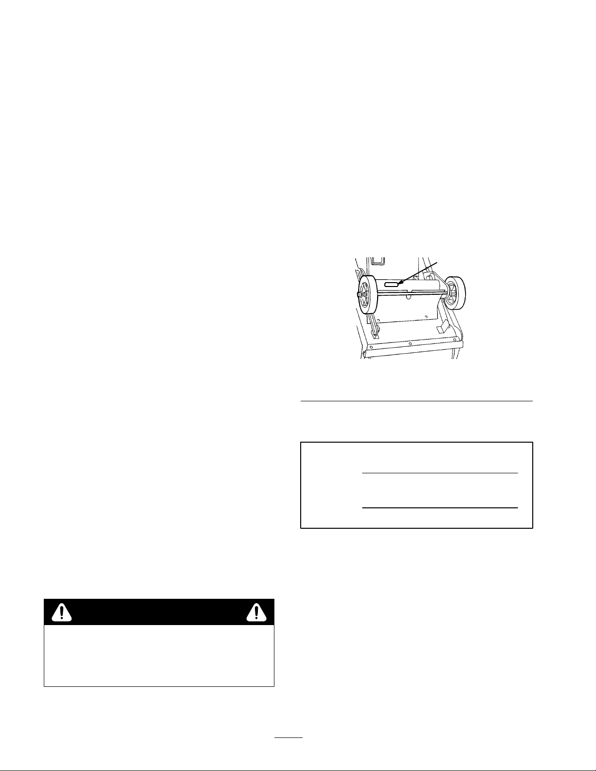
model number and serial number decal on the product as
illustrated in Figure 1.
1. Model
Write
space below:
This
safety messages that help you and others avoid personal
injury and even death. DANGER, W
CAUTION are words used to identify the level of hazard.
number and serial number decal
the product model number and serial number in the
Model
No.
Serial No.
manual identifies potential hazards and has special
.
oro product. W
oro designs and produces safe
Figure
1
e want you to
oro parts, or
. Y
ou will find the
637
ARNING, and
WARNING
The engine exhaust fr
chemicals known to the State of California to
cause cancer
harm.
The T
All Rights Reserved
, birth defects, or other r
oro Company
om this pr
– 1999
oduct contains
eproductive
DANGER
serious injury or death if you do not follow the
recommended precautions.
WARNING
or death if you do not follow the recommended
precautions.
CAUTION
moderate injury if you do not follow the recommended
precautions.
signals an extreme hazard that will cause
signals a hazard that may cause serious injury
signals a hazard that may cause minor or
2
Printed in USA
Page 3

This manual uses two other words to highlight
information.
mechanical information and
information worthy of special attention.
Important
calls attention to special
Note
emphasizes general
Safety
T
o ensur
gain knowledge of the pr
and any other operator of the snowthr
understand the contents of this manual befor
motor is ever started. Pay particular attention to the
safety alert symbol
W
instruction.” Read and understand the instruction
because it has to do with safety
instruction may r
The snowthrower is designed and tested to of
reasonably safe service; however, failur
the following instructions may r
injury.
General
The
ANSI/OPEI standard B71.3—1995 and ISO standard
8437:1989. Information or terminology specific to T
snowthrowers is enclosed in parenthesis.
e maximum safety
ARNING, OR DANGER — “personal safety
esult in personal injury
, best performance, and to
oduct, it is essential that you
ower r
ead and
e the
which means CAUTION,
. Failur
e to comply with
.
fer
e to comply with
esult in personal
Snowthrower Safety
following instructions have been adapted from the
oro
•
Do not operate the equipment without wearing
adequate winter garments. W
improve footing on slippery surfaces.
•
Handle fuel with care; it is highly flammable.
•
Use an approved fuel container
Never add fuel to a running or hot engine.
•
•
Fill fuel tank outdoors with extreme care. Never
fill fuel tank indoors.
•
Replace gasoline caps securely and wipe up spilled
fuel.
Use only the power cord supplied with the
•
snowthrower and a receptacle appropriate for use with
the cord for electric starting motors.
•
Adjust the collector (auger) housing height to clear
gravel or crushed rock surface (this is not necessary on
single-stage snowthrowers).
•
Never attempt to make any adjustments while the
engine is running, except where specifically
recommended by manufacturer (T
Let engine and machine adjust to outdoor temperatures
•
before starting to clear snow
The operation of any powered machine can result in
•
foreign objects being thrown into the eyes. Always
wear safety glasses or eye shields during operation or
while performing an adjustment or repair
ear footwear which will
.
oro).
.
.
Training
•
Read the operator’s manual carefully
familiar with the controls and the proper use of the
equipment. Know how to stop the unit and disengage
the controls quickly
Never allow children to operate the equipment. Never
•
allow adults to operate the equipment without proper
instruction.
Keep the area of operation clear of all persons,
•
particularly small children and pets.
•
Exercise caution to avoid slipping or falling, especially
when operating in reverse.
.
. Be thoroughly
Preparation
•
Thoroughly inspect the area where the equipment is to
be used and remove all doormats, sleds, boards, wires,
and other foreign objects.
•
Disengage all clutches and shift into neutral before
starting the engine.
Operation
•
Do not put hands or feet near or under rotating parts.
Keep clear of the dischar
•
Exercise extreme caution when operating on or
crossing gravel drives, walks, or roads. Stay alert for
hidden hazards or traf
After striking a foreign object, stop the engine, remove
•
the wire from the spark plug, thoroughly inspect the
snowthrower for any damage, and repair the damage
before restarting and operating the snowthrower
If the unit should start to vibrate abnormally
•
engine and check immediately for the cause. V
is generally a warning of trouble.
•
Stop the engine whenever you leave the operating
position, before unclogging the collector
(auger)/impeller housing or dischar
and when making any repairs, adjustments, or
inspections.
When cleaning, repairing, or inspecting, make certain
•
the collector/impeller (auger/impeller or rotor blades)
and all moving parts have stopped. Disconnect the
ge opening at all times.
fic.
, stop the
ge guide (chute),
.
ibration
3
Page 4

spark-plug wire, and keep the wire away from the plug
to prevent someone from accidentally starting the
engine. Disconnect the cable on electric motors.
•
Do not run the engine indoors, except when starting it
and for moving the snowthrower in or out of the
building. Open the outside doors; exhaust fumes are
dangerous.
Do not clear snow across the face of slopes. Exercise
•
extreme caution when changing direction on slopes.
Do not attempt to clear steep slopes.
•
Never operate the snowthrower without proper guards.
plates or other safety protective devices in place.
•
Never operate the snowthrower near glass enclosures,
automobiles, window wells, drop-of
proper adjustment of the snow dischar
children and pets away
Do not overload the machine capacity by attempting to
•
clear snow at too fast a rate.
•
Never operate the machine at high transport speeds on
slippery surfaces. Look behind and use care when
moving in reverse.
•
Never direct dischar
in front of the unit.
•
Disengage power to the collector/impeller
(auger/impeller or rotor blades) when snowthrower is
transported or not in use.
•
Use only attachments and accessories approved by the
manufacturer of snowthrower (T
weights, counterweights, cabs, etc. (Refer to your
Authorized Service Dealer for accessories available for
your snowthrower
Never operate the snowthrower without good visibility
•
or light. Always be sure of your footing, and keep a
firm hold on the handles. W
.
ge at bystanders or allow anyone
.)
alk; never run.
fs, etc. without
ge angle. Keep
oro), such as wheel
Maintenance and storage
• Check
•
•
•
all fasteners at frequent intervals for proper
tightness to be sure the equipment is in safe working
condition.
Never store the machine with fuel in the fuel tank
inside a building where ignition sources are present
such as hot water and space heaters, clothes dryers,
etc. Allow the engine to cool before storing in any
enclosure.
Always refer to this operator’s manual for important
details if the snowthrower is to be stored for an
extended period.
Maintain or replace safety and instruction labels, as
necessary.
Run the machine a few minutes after throwing snow to
•
prevent freeze-up of the collector (auger)/impeller
ith the engine running, pull the recoil starter handle
(W
several times.)
Toro
The
T
know that is not included in the ANSI or ISO standards.
•
•
•
• Before
•
•
•
•
•
•
•
•
Snowthrower Safety
following list contains safety information specific to
oro products or other safety information that you must
The r
otating impeller/auger or r
off or injur
handles and away from the dischar
operating the snowthrower
feet, and any other part of your body or clothing
away fr
Before adjusting, cleaning, repairing, and inspecting
the snowthrower, and before unclogging the dischar
chute,
all moving parts to stop
the spark plug and keep it away from the plug to
prevent someone from accidentally starting the engine.
Use a stick,
from the dischar
handles, stop the engine, remove the key
all moving parts to stop.
Do not wear loose fitting clothing that could possibly
get caught in moving parts.
If a shield, safely device, or decal is damaged,
illegible, or lost, repair or replace it before beginning
operation. Also, tighten any loose fasteners.
Do not
For two-stage snowthrowers, use the lower gear and, if
applicable, the rear wheel position when operating on
slopes.
Do not
Do not touch the engine while it is running or soon
after it is stopped because the engine will be hot
enough to cause a burn. Do not add oil or check the
oil level in the crankcase when the engine is running.
Perform only those maintenance instructions described
in this manual. Before performing any maintenance,
service, or adjustment, stop the engine, remove the key
and pull the wire from the spark plug, keeping it away
from the plug to prevent someone from accidentally
starting the engine. If major repairs are ever needed,
contact your Authorized Toro Service Dealer
Do not over speed the engine by changing the
governor settings.
e fingers or hands.
. Keep your face hands,
om concealed, moving, or r
stop the engine, r
not your hands
ge chute.
leaving the operator’s position behind the
smoke while handling gasoline.
use the snowthrower on a roof.
emove the key
. Also, pull the wire of
otor blades can cut
Stay behind the
ge opening while
otating parts.
, and wait for
to remove obstructions
, and wait for
.
f of
.
ge
4
Page 5
•
When storing the snowthrower for more than 30 days,
drain the gasoline from the fuel tank to prevent a
potential hazard. Store gasoline in a safety approved,
red metal container
switch before storing the snowthrower
. Remove the key from the ignition
.
o ensure the best performance and safety
• T
only genuine T
to keep the T
eplacement parts and accessories as they could
r
cause a safety hazard.
oro replacement parts and accessories
oro all T
oro.
Do not use “W
, purchase
ill Fit”
Safety
On
(Part No. 60-9480)
and Instruction Decals
Safety
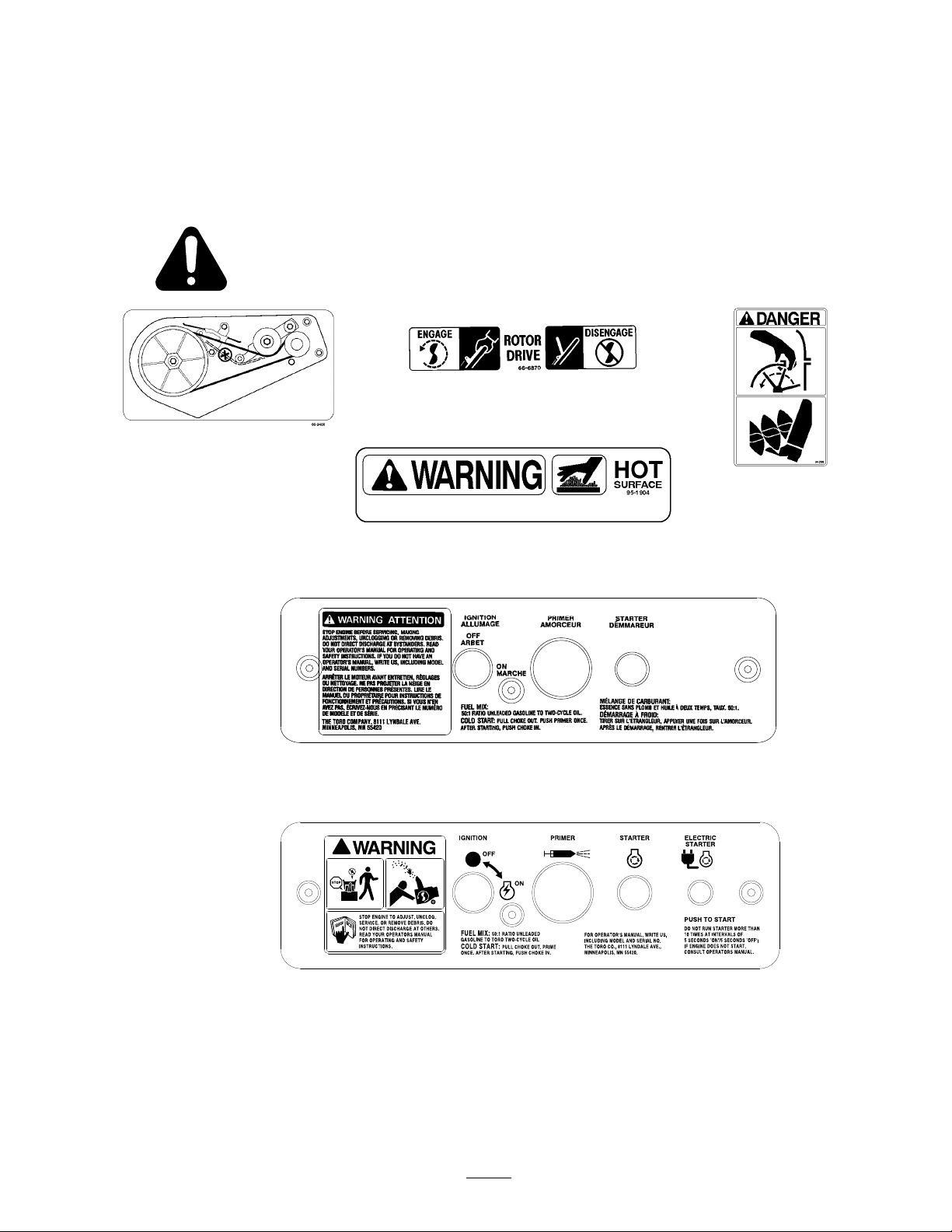
decals and instructions are easily visible to the operator and are located near any
area of potential danger
Inside of Belt Cover
. Replace any decal that is damaged or lost.
On Handle
(Part No. 66-6870)
On Chute
(Part No. 94-2900)
By Muffler
(Part No. 95-1904)
Replace Control Panel for Models 38413 and 38440
(Part No. 55-9350)
Replace Control Panel for Models 38419, 38439, and 38445
(Part No. 61-4410)
5
Page 6
Assembly
Note:
Determine the left and right sides of the snowthrower by standing in the normal operating position.
Loose
DESCRIPTION QTY. USE
Carriage
Locknuts
Discharge chute
Plastic bushing
Capscrews
Locknuts
Chute crank and mounting bracket
Installing
Models 38413 and 38419 only
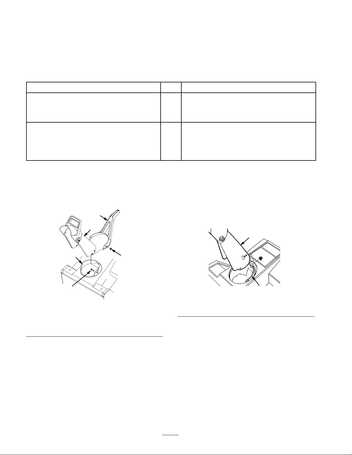
1. Place
Parts
bolts
the Discharge Chute
the chute handle over the chute ring (Fig. 2).
3
3
1
1
2
2
1
Installing the discharge chute
Installing the chute crank (Models 38439,
38440, and 38445 only)
5.
Install the carriage bolts and the locknuts through the
remaining holes, with the locknuts on the outside.
6. T
ighten all locknuts
securely.
Models 38439, 38440, and 38445 only
3
1. Set
the dischar
2
ge chute over the chute ring (Fig. 3).
2
1
4
Figure
1. Chute
2.
3.
2. Insert
3.
Note: You can rotate the chute ring for easier assembly
4.
ring
Discharge chute
Chute handle
the dischar
the chute handle. (Fig. 2).
Align the hole in the back of the chute with the center
hole in the ring.
Install a carriage bolt and a locknut through the center
holes, with the locknut on the outside.
ge chute between the chute ring and
2
4.
5. Locknut
5
m-3277
Carriage bolt
1
Figure
1. Chute
2. Align
3.
Note: You can rotate the chute ring for easier assembly
4.
.
5. T
ring
the hole in the back of the chute with the center
hole in the ring (Fig. 3)
Install a carriage bolt and a locknut through the center
holes, with the locknut on the outside (Fig. 3)
Install carriage bolts and locknuts through the
remaining holes, with the locknuts on the outside.
ighten all locknuts
securely.
3
2.
Discharge chute
636
.
6
Page 7
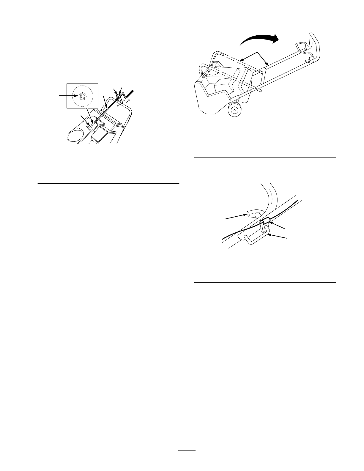
Installing
the Chute Crank
Models 38439, 38440, and 38445 only
1. Insert
1. Chute
2.
3. Gear
2. Slowly
3.
4.
the flattened end of the chute crank through the
hole in the shroud while aligning the mounting bracket
with the holes in the lower handle (Fig. 4).
4
2
5
893
1
3
635
Figure
crank
Mounting bracket
4
4.
Plastic bushing
5.
Hidden gear opening
rotate the crank until the flattened end fits into
the hidden gear opening and the chute ring turns with
the crank (Fig. 4).
Fully insert the plastic bushing into the hole in the
mounting bracket (Fig. 4).
Secure the mounting bracket to the handle with two
capscrews and locknuts (Fig. 4).
1
Figure
1. Upper
Note:
handle
Ensure that the cable guide is in the position as
5
shown in Figure 6.
1
2
3
Unfolding
1. Cut
the tie that secures the control cable to the handle.
2.
Loosen the knobs and pull out the handle locks until
the Handle
the upper handle rotates freely (Fig. 6).
3.
Position the upper handle as shown in Figure 5.
1. Knob
2. Handle
4. Insert
Figure
lock
the loose end of the control cable into the top
6
3.
Cable guide
hole of the control bar as illustrated in Figure 7
(models 38413 and 38419) or into the bottom hole as
illustrated in Figure 8 (models 38439, 38440, and
38445).
7
Page 8
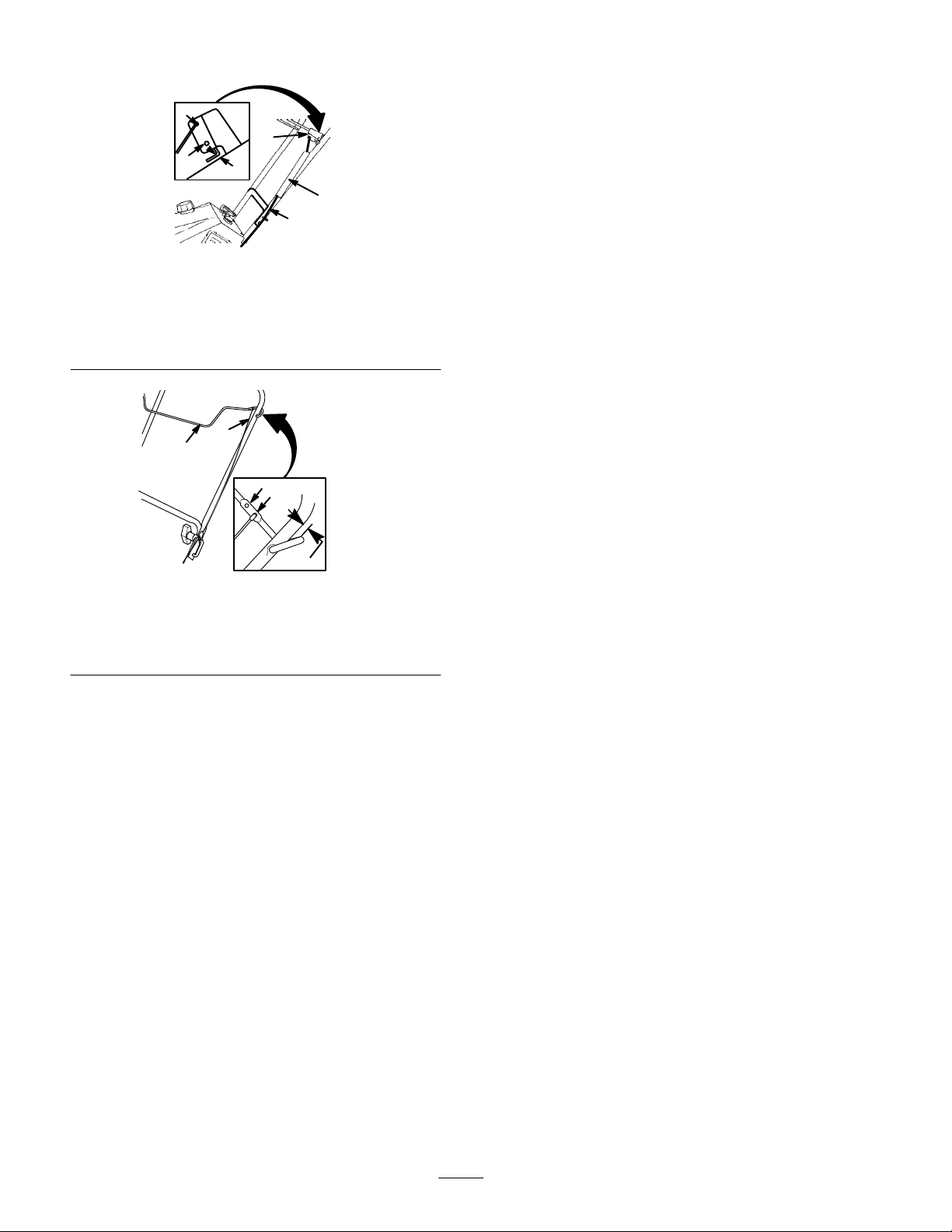
1. Control
2.
3.
4. T
cable
Spring cover
Control bar bracket
op hole
4
3
5
6
2
1
m-2708
Figure
7
5.
Bottom hole
6.
1/16 to 1/8 in. (0.16 to
0.32 cm) gap
Before
Mixing
Use
only clean, fresh, lead-free gasoline (including
oxygenated or reformulated gasoline) with an octane
rating of 87 or higher
the amount of gasoline you expect to use in 30 days.
Using unleaded gasoline results in fewer combustion
chamber deposits and longer spark plug life.
IMPORTANT
containing methanol, gasohol containing mor
10% ethanol, pr
these fuels can damage the engine’
Starting
Gasoline and Oil
. T
o ensure freshness, purchase only
: Do not use methanol, gasoline
emium gasoline, or white gas. Using
s fuel system.
e than
1
2
3
4
5
m–4017/4012
Figure
1. Cable
2. Control
3. T
5. Fully
6. T
7.
bar bracket
op hole
insert the handle locks.
ighten the knobs until they are snug.
Ensure that a 1/16 to 1/8 in. (0.16 to 0.32 cm) gap
8
4.
Bottom hole
5.
1/16 to 1/8 in. (0.16 to
0.32 cm) gap
exists between the control bar and the handle (Refer to
Adjusting the Contr
ol Cable
on page 12).
IMPORTANT
: Do not use automotive oil (i.e., SAE 30,
10W30, etc.), a two-cycle oil that is not NMMA- or
TCW
-certified, or a fuel mixed at the wr
ong
gasoline/oil ratio. This can cause engine damage not
cover
ed under the Toro warranty
.
8
Page 9

DANGER
DANGER
POTENTIAL HAZARD
•
In certain conditions gasoline is extr
flammable and highly explosive.
WHA
T CAN HAPPEN
•
A fir
e or explosion fr
others, and cause pr
HOW T
•
•
•
• Stor
•
O AVOID THE HAZARD
Use a funnel and fill the fuel tank outdoors, in
an open ar
any gasoline that spills.
Do not fill the fuel tank completely full. Add
gasoline to the fuel tank until the level is 1/4” to
1/2” (6 mm to 13 mm) below the bottom of the
filler neck. This empty space in the tank allows
gasoline to expand.
Never smoke when handling gasoline, and stay
away fr
fumes may be ignited by a spark.
keep it out of the r
Never buy mor
gasoline.
ea, when the engine is cold. W
om an open flame or wher
e gasoline in an appr
om gasoline can burn you,
operty damage.
oved container and
each of childr
e than a 30-day supply of
emely
e gasoline
en.
ipe up
POTENTIAL HAZARD
•
When fueling, under certain cir
static charge can develop, igniting the gasoline.
WHA
T CAN HAPPEN
•
A fir
e or explosion fr
and others and cause pr
HOW T
•
•
•
•
•
O AVOID THE HAZARD
Always place gasoline containers on the gr
away from your vehicle befor
Do not fill gasoline containers inside a vehicle
or on a truck or trailer bed because interior
carpets or plastic truck bed liners may insulate
the container and slow the loss of any static
charge.
When practical, r
equipment fr
the equipment with its wheels on the gr
If this is not possible, then refuel such
equipment on a truck or trailer fr
container
dispenser nozzle.
If a gasoline dispenser nozzle must be used,
keep the nozzle in contact with the rim of the
fuel tank or container opening at all times until
fueling is complete.
om the truck or trailer and r
, rather than fr
om gasoline can burn you
operty damage.
emove gas-power
om a gasoline
cumstances, a
e filling.
ed
ound.
om a portable
ound
efuel
1.
Pour a half gallon (1.9 liters) of gasoline into an
approved gasoline container
Do not mix gasoline and oil in the fuel tank. Oil at
Note:
room temperature mixes easier and more thoroughly than
cold oil. Oil below 32°F (0°C) requires additional mixing.
2.
Add the proper amount of high grade, NMMA- or
TCW
-certified two-cycle oil as directed on the
container label.
For best results, use
Install the cap on the gasoline container and shake the
3.
container to mix the gasoline and oil thoroughly
Remove the cap and add the remaining gasoline.
4.
Tor
.
o 50:1 T
wo-Cycle Oil
.
.
9
Page 10
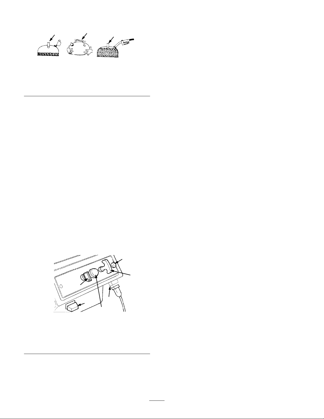
1
1. Add
oil to small amount of
gasoline
2.
Install cap and shake can
to mix
We
recommend using a stabilizer/conditioner for all T
gasoline-powered products during operation and storage.
A fuel stabilizer/conditioner cleans the engine during
operation and prevents gum-like varnish deposits from
forming in the engine during storage. A fuel
stabilizer/conditioner works best when you mix it with
fresh gasoline.
Note:
If you use
Engine Oil with Fuel Stabilizer
fuel stabilizer/conditioner
IMPORTANT
stabilizer during storage. Do not use fuel stabilizers
with an alcohol base such as ethanol, methanol, or
isopropanol.
Tor
o Heavy Duty 50:1 All Season 2-Cycle
: Do not use fuel additives except a fuel
2
Figure
9
3.
, you do not need to add a
.
3
Add remaining amount of
gasoline
111
oro
2.
Cover the hole in the center of the primer with your
thumb and push the primer in twice. In extremely cold
temperatures, repeat this step as necessary
Do not use the choke and the primer when starting a
Note:
warm engine.
3.
For a r
ecoil starter:
hand and pull the recoil starter vigorously with the
other hand.
For an electric starter:
A.
Connect the power cord to the snowthrower and to
a standard household power outlet.
B.
Push the starter button.
Run the electric starter no more than ten times at
intervals of five seconds on, then five seconds of
If the engine does not start after this attempt, wait
at least 40 minutes to allow the starter to cool
before attempting to start it again.
IMPORTANT
can overheat and damage the starter
If the engine does not start after the second
attempt, bring the snowthrower to an Authorized
Service Dealer for service.
C.
When the engine starts, disconnect the power cord
from the snowthrower and the outlet.
: Running the electric starter extensively
Hold the snowthrower with one
.
.
f.
Operation
Operating
The
snowthrower control panel contains a key switch, a
primer
, a recoil starter
choke is just below the control panel (Fig. 10).
1. Key
switch
2. Primer
3.
Recoil start
4. Choke
Starting
1. Turn
the key to the On position and pull the choke out.
Controls
, and an electric start button. The
1
4
2
Figure
10
Elec. start button (electric
5.
start models only)
6.
Cord connection (electric
start models only)
the Engine
6
4. W
ith the engine running, push in the choke slowly
Stopping
Turn
the key to the Of
parts to stop before leaving the operating position.
5
3
Starting
To
start the rotor blades, squeeze the control bar and
handle together
Stopping
642
Release
Note:
stop, but the engine continues to run.
the control bar to stop the rotor blades.
When you release the control bar
Adjusting
the Engine
f position, and wait for all moving
the Rotor Blades
.
the Rotor Blades
, the rotor blades
the Discharge Chute
.
Models 38413 and 38419 only
Move
the chute handle left and right to adjust the
direction of the snow stream (Fig. 1
handle on top of the discharge chute controls the height of
the snow stream.
mounting locknuts.
Do not overtighten the chute deflector
1). The chute deflector
10
Page 11
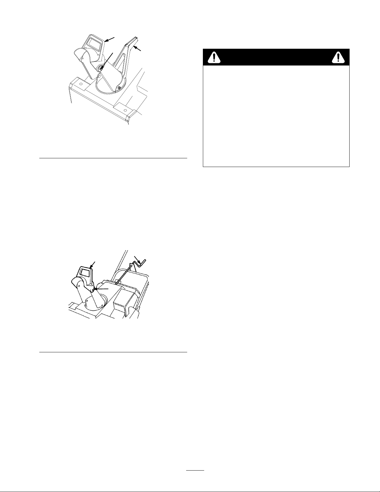
2
Throwing
Snow
3
1
m-3278
Figure 11
1. Chute
2.
IMPORTANT:
snowthrower
handle
Chute deflector handle
Do not use the chute handle to lift the
. This can damage the chute handle.
3.
Deflector mounting
locknuts
Models 38439, 38440, and 38445 only
Rotate
the chute crank clockwise to move the dischar
chute to the right or counterclockwise to move the chute
to the left (Fig. 12). The chute deflector handle on top of
the dischar
ge chute controls the height of the snow stream.
Do not overtighten the chute deflector mounting
locknuts.
2
1
3
ge
WARNING
POTENTIAL
•
Stones, toys and other foreign objects may be
picked up and thr
WHA
T CAN HAPPEN
• Thr
own objects can cause serious personal
injury to operator or bystanders.
HOW T
•
Keep the ar
that could be picked up and thr
blades.
Keep all childr
•
operation.
•
The snowthrower clears down to the ground and
propels itself forward when you raise the handle. The
snowthrower tilts
strike the ground. The wheels do not need to touch the
ground to self-propel. The more you tilt the handle
forward, the faster the snowthrower self-propels.
•
Always overlap each swath and dischar
downwind whenever possible.
• T
o clear snow from crushed rock or gravel, push down
on the handle to raise the rotor blades clear of the
loose material and push the snowthrower forward.
•
In snowy and cold conditions, some controls and
moving parts may freeze solid.
for
ce when trying to operate fr
have dif
engine and let it run for a few minutes.
HAZARD
own by the r
otor blades.
O AVOID THE HAZARD
ea to be clear
en and pets away fr
slightly
ed fr
ee of all objects
own by r
om ar
otor
ea of
forward so that rotor blades
ge the snow
Do not use excessive
ozen contr
ols.
ficulty operating any control or part, start the
If you
1. Chute
2.
crank
Chute deflector handle
Figure
12
3.
Deflector mounting
locknuts
629
11
•
After clearing the snow
, let the engine run for a few
minutes to prevent moving parts from freezing. Shut
of
f the engine and remove all ice and snow from the
snowthrower. On models 38439, 38440, and 38445:
Operate the chute crank several times to remove any
ice and snow
.
Page 12
Maintenance
Recommended
Service
Control cable
Fuel tank
Scraper
Drive belt
Spark plug
Rotor blades
Tighten
fasteners
Item
Check the control cable. Adjust if necessary
Drain the fuel and run the engine until the fuel tank
and the carburetor are dry
Check the scraper
Inspect the drive belt. Replace if necessary
Clean, inspect, and gap. Replace if necessary
Inspect the rotor blades. Replace if necessary
Check and for loose fasteners and tighten them if
necessary.
POTENTIAL
•
If you leave the wir
WHA
T CAN HAPPEN
•
Someone accidentally starting the engine could seriously injur
HOW T
•
Pull the wir
does not accidentally contact the spark plug.
HAZARD
O AVOID THE HAZARD
e off of the spark plug befor
Maintenance Schedule
Service Operation
. X X
.
. Replace if necessary
CAUTION
e on the spark plug, someone could start the engine.
e you do any maintenance. Also, push it aside so it
. X
. X
. X
. X
Initial Annually Comments
Check and adjust
as needed.
X
T
X X
e you or other bystanders.
ighten fasteners
as needed.
Adjusting
Periodically
adjustment.
Stop the engine and wait for all moving parts to stop.
1.
2.
Move the control bar back toward the handle to
remove the slack in the cable (Fig. 7 or Fig. 8).
3.
Ensure that a 1/16 to 1/8 in. (0.16 to 0.32 cm) gap
exists between the control bar and the handle (Refer to
the inset in Fig. 7). T
Note: The control cable must have slack in the
disengaged position.
4.
Adjust the cable as follows:
Models 38413 and 38419 only:
A.
Unhook the spring end from the top hole in the
control bar bracket (Fig. 7).
B.
Slide the spring cover of
adjuster.
the Control Cable
check the control cable for proper
o adjust the cable, go to step 4.
f the spring and the cable
Unhook the Z fitting from the cable adjuster and
C.
reposition the Z fitting in the top or bottom hole on
the adjuster to obtain a proper gap of 1/16 to 1/8 in.
(0.16 to 0.32 cm) between the control bar bracket
and the handle (Fig. 13).
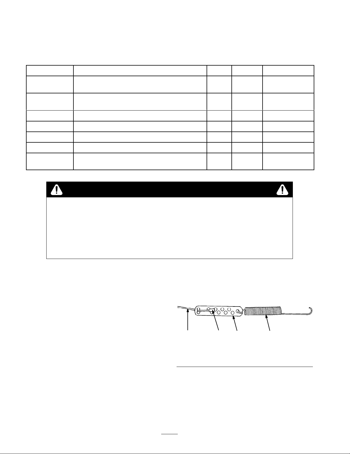
4321
Figure
1. Spring
2. Cable
adjuster
D. Install
E.
Models 38439, 38440, and 38445 only:
the spring cover over the cable adjuster and
the spring.
Hook the spring into the top hole of the control bar
bracket (Fig. 7).
13
3.
Z fitting
4. Cable
897
12
Page 13
A.
Unhook the upper cable end from the hole in the
control bar bracket (Fig. 7).
B.
Slide the spring cover up the cable to expose the
cable adjuster (Fig. 7).
C.
Unhook the Z fitting from the cable adjuster and
position it in the top or bottom hole on the adjuster
to obtain a gap of 1/16 to 1/8 in. (0.16 to 0.32 cm)
between the control bar bracket and the handle
(Fig. 13).
D.
Install the spring cover over the cable adjuster
Install the upper cable end into the bottom hole in
E.
the control bar bracket (Fig. 8).
2
3
1. Spring
2.
Z fitting
Figure
cover
14
3.
Cable adjuster
1
630
2.
Remove the fuel tank cap and use a pump-type syphon
to drain the fuel into a clean gasoline container
Start the engine and allow it to run until it consumes
3.
.
all the fuel in the fuel tank and stops running. Repeat
this step two more times to ensure that the fuel tank is
empty.
Replacing
Before
.
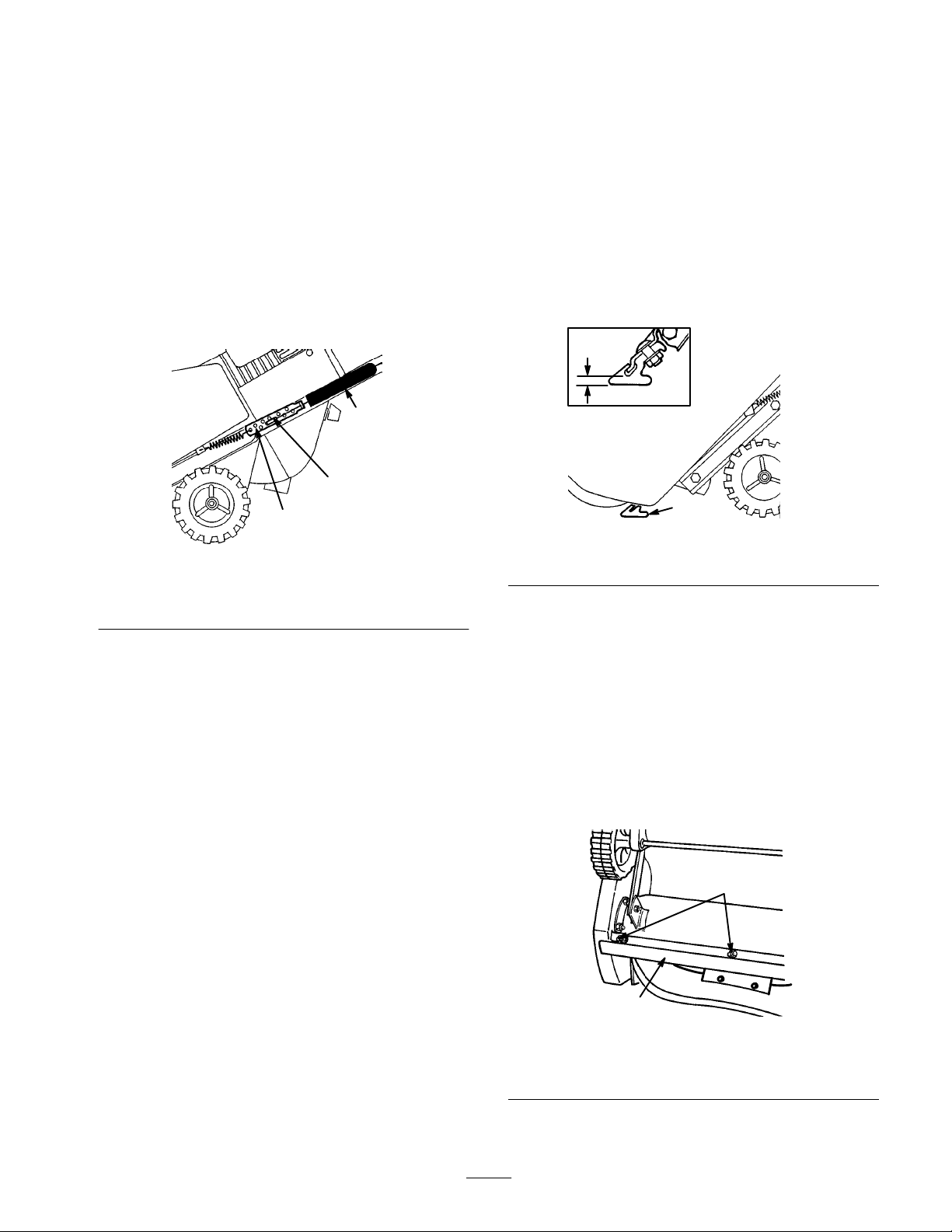
each season, inspect the scraper for wear
thickness of the scraper’s bottom is less than 1/16 in.
the Scraper
. If the
(1.6 mm), replace the scraper (Fig. 15).
2
1
Figure
1. Scraper 2. 1/16
Note:
The running time and the roughness of the driveway
15
in.
634
or sidewalk determines the scraper wear rate.
5. Check
the adjustment (refer to steps 2 and 3 above).
After extended use, the drive belt may wear and lose its
proper belt tension. Improper belt tension causes belt
slippage and decreases the performance under a heavy
load. Belt slippage may occur after two or three seasons of
normal usage (10 to 15 hours). If the drive belt slips
(continuously squeals) under a heavy load, increase the
belt tension by doing one of the following steps:
•
For Models 38413 and 38419:
Reposition the spring
end in the bottom hole of the control bar bracket
(Fig. 7).
•
For Models 38439, 38440, and 38445:
Reposition the
upper cable end into the upper hole of the control bar
bracket (Fig. 8).
Using the incorrect adjusting hole in the control bar
bracket can reduce the drive belt life. Occasional belt
slippage (squealing) may occur in extremely wet
conditions due to moisture in the drive system. T
o remove
moisture, start the rotor and operate it without a load for
30 seconds. Once you remove the moisture, the drive belt
should not slip.
Emptying
the Fuel T
ank
1.
Stop the engine.
2.
Drain the fuel from the fuel tank. Refer to
the Fuel T
3. T
ip the snowthrower forward onto its front housing.
4.
Remove three carriage bolts and the locknuts holding
ank
on page 13.
Emptying
scraper in place (Fig. 16).
5.
Remove the scraper by sliding it to the right and down.
2
1
Figure
1. Scraper 2. Carriage
16
locknuts
644
bolts and
1. Stop
the engine and remove the key from the switch.
13
Page 14
6. Install
the new scraper to the housing using the
carriage bolts and locknuts.
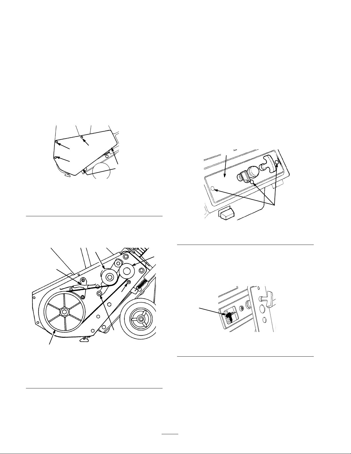
4. Loop
the new drive belt around the engine pulley
under the idler pulley
brake assembly
,
, over the roller
, through the
, and around the rotor pulley (Fig. 18).
Replacing
Inspect
the drive belt before each season, and replace it if
the Drive Belt
it is worn or damaged.
1.
Stop the engine.
2.
Remove three self tapping screws, two capscrews, one
washer
, and two locknuts that secure the belt cover to
the snowthrower frame (Fig. 17). Set the drive belt
cover aside.
2
3
1
4
631
1. Cap screw
2. Capscrew
washer
3. Push
, locknut
, locknut,
down on the idler pulley and remove the drive
belt from the rotor pulley
Figure
17
3.
Long self tapping screw
4.
Short self tapping screws
, the brake arm assembly, and
the engine pulley (Fig. 18).
IMPORTANT:
The drive belt must be on top of the roller
as shown in Figure 18.
5.
Install the drive belt cover
securely
Replacing
Before
, but
do not overtighten
the Spark Plug
each season, check the spark plug. If the electrodes
. T
ighten the fasteners
.
in the center of the plug are dark or have deteriorated,
install a new NGK BPMR4A spark plug.
1.
Remove the three mounting screws that secure the
control panel to the housing (Fig. 19).
1
2
643
1. Control
Figure
panel
19
2.
Mounting screws
1. Engine
2.
Idler pulley
3. Roller
4
5
pulley
2
Figure
6
3
18
4.
Brake arm assembly
5.
Rotor pulley
6.
Belt guide
1
626
2. Remove
the ignition key and lift of
f the panel,
allowing it to hang on the recoil rope.
3.
Pull the wire of
f the spark plug and remove the spark
plug (Fig. 20).
1
628
1. Spark
4. Examine
plug wire
the spark plug and replace it if it is cracked,
fouled, or dirty
IMPORTANT
Figure
.
: Do not sandblast, scrape, or clean the
20
spark plug. Dirt may fall into the cylinder and cause
engine damage.
14
Page 15
5.
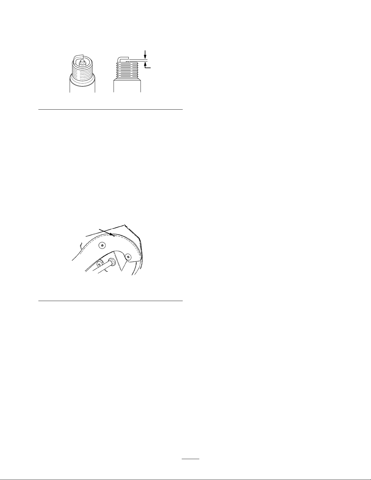
Set the spark plug gap (Fig. 21) between the electrodes
to .032 in. (.81 mm).
.032 in.
(.81 mm)
Figure
6. Install
7.
8.
Replacing
Before
When a rotor blade edge has worn to the wear indicator
hole (Fig. 22), replace
performance and to prevent damage to the underside of
the snowthrower
the spark plug and torque it to 15 ft-lb
(20.4 Nm). If you do not have a torque wrench,
tighten the plug firmly
Push the wire onto the spark plug.
Install the control panel with the capscrews.
the Rotor Blades
each season, inspect the rotor blades for wear
both
.
21
.
.
rotor blades to ensure proper
Note:
Replace the scraper whenever you replace the rotor
blades. This ensures proper snowthrower operation and
performance.
The running time and the roughness of the driveway
Note:
or the sidewalk determines the wear rate of the rotor
blades.
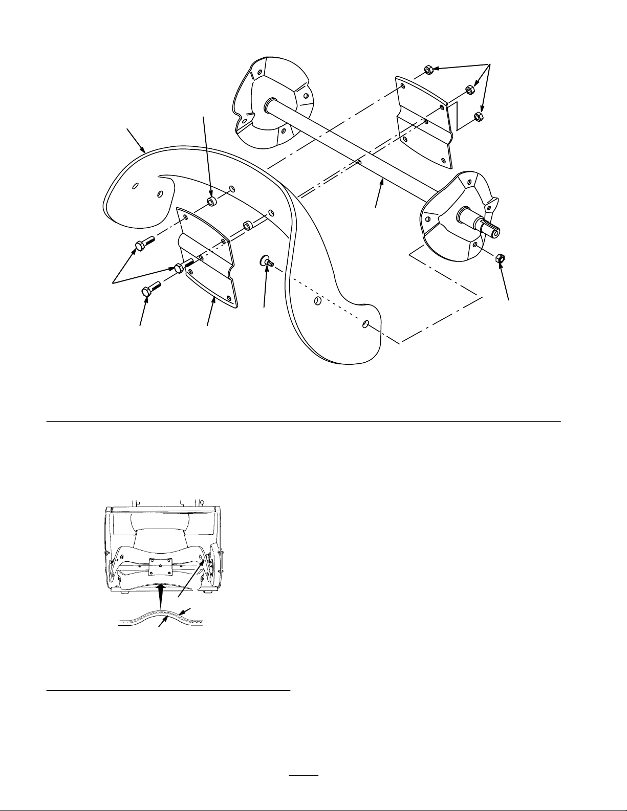
Removing the Old Blade
Note: You will need a No. T27 torx driver to complete
this procedure.
1.
Remove four torx screws and four locknuts that secure
the outer edges of the rotor blade to the rotor shaft
assembly (Fig. 23).
2.
Remove two hex-head capscrews, spacers, and
locknuts that secure the center of the blade to the rotor
halves (Fig. 23).
3.
Loosen the hex-head screw securing the rotor halves to
the auger shaft assembly (Fig. 23).
4.
Slide the blade out from between the rotor halves
(Fig. 23).
1. Wear
indicator hole
1
Figure
22
15
Page 16
4
6
1
7
5
1. Rotor
2.
Rotor half
8
blade
2
3. Torx screw
4. Locknut
Installing a New Blade
1. Examine
layer thickness (Fig. 24). Some rotor blades have a
part number on the thick side of the blade.
1. Thin
2.
Thick layer
a new rotor blade edge for the dif
3
2
Figure
layer
24
3. W
1
681
ear indicator hole
3
ference in
Figure
23
5.
Hex-head capscrew
6. Spacer
2.
Insert the new rotor blade between the rotor halves.
3.
Secure the rotor blade to the rotor halves with two
Auger shaft assembly
7.
8.
Hex-head screw
hex-head capscrews, two spacers, and two locknuts,
positioning the bolt heads on the thick side of the
blade (Fig. 23).
4.
Curve the rotor blade and secure it with the remaining
torx screws and locknuts, positioning the screw heads
on the thick side of the blade (Fig. 23).
5. T
ighten all screws and locknuts securely
.
Storage
Preparing
1. Add
Note:
mix it with fresh gasoline.
a fuel stabilizer/conditioner to the gasoline in the
fuel tank as directed.
A fuel stabilizer/conditioner works best when you
the Fuel System
4
680
Install
the rotor blades with the thick layer on the
inside
of the curve. (Fig. 24). If you do not install the
blades properly
, the blades may be out of balance and
cause the snowthrower to “hop” or “bounce.”
Note:
If you use
Tor
Engine Oil with Fuel Stabilizer
fuel stabilizer/conditioner
16
o Heavy Duty 50:1 All Season 2-Cycle
, you do not need to add a
.
Page 17

2.
Run the engine for five minutes to distribute the
conditioned fuel through the fuel system.
3.
Stop the engine, allow it to cool, and drain the fuel
tank.
Start the engine again and run it until it stops.
4.
5.
Prime the engine, start it a third time, and run it until it
will not restart.
6.
Recycle the fuel according to local codes.
Preparing
This
procedure allows you to close both the intake and the
exhaust ports of the engine, preventing cylinder bore
corrosion.
Slowly pull the recoil starter until you feel resistance
1.
due to compression pressure, then stop.
2.
Release the starter tension slowly to prevent the engine
from reversing due to compression pressure.
Tightening
the Engine
the Fasteners and
Cleaning the Snowthrower
1. Tighten
replace damaged parts.
2.
Clean the snowthrower thoroughly
Covering
all loose screws, bolts, and locknuts. Repair or
.
and Storing the
Snowthrower
Cover
the snowthrower and store it in a clean, dry place
out of the reach of children.
IMPORTANT
position and on its wheels. Storing the snowthr
its fr
ont housing may cause hard starting.
: Stor
e the snowthrower in its operating
WARNING
POTENTIAL HAZARD
•
Gasoline is highly flammable, explosive, and
danger
WHA
•
If gasoline contacts a flame or is inhaled,
serious personal injury can occur
HOW T
•
Never stor
ar
be pr
clothes dryers.
•
Allow the engine to cool befor
snowthr
ous if inhaled.
T CAN HAPPEN
.
O AVOID THE HAZARD
e the snowthrower in a house (living
ea) or a basement wher
esent, such as hot water and space heaters,
ower in an enclosur
e ignition sour
e storing the
e.
ces may
ower on
17
Page 18

Federal
The U.S. Environmental Protection Agency (EP
explain the emission control system warranty on your 1995 and later utility/lawn/garden equipment engine. In California,
new utility/lawn/garden equipment engines must be designed, built and equipped to meet the State’
standards. In other states, new 1997 and later model year utility/lawn/garden equipment engines must be designed, built
and equipped, at the time of sale, to meet the U.S. EPA regulations for small nonroad engines. The equipment engine must
be free from defects in materials and workmanship which cause it to fail to conform with U.S. EPA standards for the first
two years of engine use from the date of sale to the ultimate purchaser
your utility/lawn/garden equipment engine for the period of time listed above provided there has been no abuse, neglect or
improper maintenance of your utility/lawn/garden equipment engine.
Y
our emission control system may include parts such as the carburetor or fuel injection system, the ignition system, and
catalytic converter
Where a warrantable condition exists, T
and California Emission Control W
A T
wo Y
ear Limited W
our W
Y
. Also included may be hoses, belts, and connectors and other emission related assemblies.
oro will repair your engine at no cost to you including diagnosis, parts and labor
arranty Rights and Obligations
A), the California Air Resources Board (CARB) and Toro are pleased to
arranty
. T
oro must warrant the emission control system on
arranty Statement
s stringent anti–smog
.
Manufacturer’s
Utility/Lawn/Garden
part on your engine is defective in materials or workmanship, the part will be repaired or replaced by T
charge.
Owner’s
W
• As
the engine owner
manual. T
deny warranty solely for the lack of receipts or for your failure to ensure the performance of all scheduled
maintenance.
Any replacement part or service that is equivalent in performance and durability may be used in non–warranty
•
maintenance or repairs, and shall not reduce the warranty obligations of the engine manufacturer
As the engine owner
•
part has failed due to abuse, neglect, improper maintenance or unapproved modifications or parts.
• Y
ou are responsible for presenting your equipment engine to a T
The warranty repairs should be completed in a reasonable amount of time, not to exceed 30 days.
•
If you have any questions regarding your warranty rights and responsibilities or if you need a referral to a T
Service Dealer
W
arranty Coverage:
equipment engines are warranted for two years from the date of delivery
arranty Responsibilities:
, you are responsible for the performance of the required maintenance listed in your owner
oro recommends that you retain all receipts covering maintenance on your equipment, but T
, you should, however
, please feel free to contact us at the following address:
, be aware that T
T
oro Customer Service Department
811
1 L
yndale A
Bloomington, MN 55420–1
612–888–8801
800–348–2424
oro may deny you warranty coverage if your engine or a
ORO Service Dealer as soon as a problem exists.
venue South
196
. If any emission–related
oro free of
’s
oro cannot
.
ORO
Warranted
The
warrants to the initial owner and each subsequent purchaser that the engine is free from defects in materials and
workmanship which cause the engine to fail to conform with applicable regulations for a period of two years.
Failures caused by abuse, neglect, or improper maintenance are not covered. The use of add–on or modified parts can
be grounds for disallowing a warranty claim. The manufacturer is not liable to cover failures of warranted parts caused
by the use of add–on or modified parts. T
a warranted part still under warranty
defined by the manufacturer in the written instructions.
Any warranted part which is not scheduled for replacement as required maintenance, or which is scheduled only for
regular inspection to the effect of ”repair or replace as necessary” shall be warranted for the warranty period. Any
warranted part which is scheduled for replacement as required maintenance shall be warranted for the period of time up
to the first scheduled replacement point for that part. Coverage under this warranty extends only to the parts listed
below (the emissions system parts) to the extent that these parts were present on the engine when purchased.
Parts:
warranty period begins on the date the engine or equipment is delivered to a retail purchaser
oro is liable for damages to other engine components caused by the failure of
. The owner is responsible for the performance of the required maintenance, as
. The manufacturer
18
Rev
. 10/26/1998
Page 19

–
Fuel Metering System
•
Cold start enrichment system including the choke mechanism or priming system
•
Fuel pump
•
Air fuel ratio feed back system
•
Carburetor and internal parts
•
Fuel injection system
–
Air Induction System
•
Air cleaner
•
Reed intake system
•
Intake manifold
•
Controlled hot air intake system
–
Ignition System
•
Spark plug(s)
•
Ignition coils and electronics
•
Advance/retard mechanisms
–
Catalytic Converter/Thermal Reactor System
•
Catalytic converter
•
Thermal reactor
•
Exhaust manifold
–
Air Injection System
•
Air injection system or pulse valve
• V
alves af
fecting distribution of air
–
Exhaust Gas Recirculation (EGR) System
•
EGR valve body and piping system connecting to the intake side of the engine
•
EGR control system
–
Particulate Controls
• T
raps filters, precipators and any other device used to capture particulate emissions
–
Miscellaneous Items Used in the Above Systems
• V
acuum, temperature, and time sensitive valves and switches
•
Electronic controls
•
Hoses, connectors, and assemblies of same
How
to Get W
Should
Authorized T
good reference source. The dealer will either arrange service at his/her dealership or recommend another Authorized
Service Dealer who may be more convenient. Y
etc.) for warranty validation. The owner shall not be char
a warranted part is defective, if the diagnostic work is performed at a warranty station.
The Toro Company is not liable for indir
T
ORO Pr
warranted part still under warranty
the above exclusion may not apply to you.
arranty Service:
you feel your T
ORO Service Dealer or T
oducts cover
ORO Product requires warranty service, contact the dealer who sold you the product or any
ed by this warranty
ORO Master Service Dealer
ou may need proof of purchase (copy of registration card, sales receipt,
ged for diagnostic labor which leads to the determination that
ect, incidental or consequential damages in connection with the use of the
, except for damages to other engine components caused by the failur
. Some states do not allow exclusions of incidental or consequential damages, so
. The Y
ellow Pages of your telephone directory is a
e of a
This warranty gives you specific legal rights, and you may also have other rights which vary fr
19
om state to state.
Page 20

The Toro Total Coverage
Gas
Powered
Snow
Products
A Full Two-Year Warranty
(Limited Warranty for Commercial Use)
What
Is Covered By This Express W
The Toro Company promises to repair any T
for normal residential purposes* if defective in materials or
workmanship for a period of two years from the date of pur
chase. For single stage snowthrowers, the cost of parts and
labor is included, but the customer pays the transportation
costs.
T
ransportation within a 15 mile radius of the servicing dealer
is covered under this warranty for two-stage snowthrowers.
What
Products Are Covered By This W
This
warranty applies to all gasoline powered snow products.
How
About Commercial Use?
Toro
Consumer Products used for commercial, institutional or
rental use are covered by a limited warranty for 45 days from
the date of purchase.
How
Do Y
ou Get W
Should
you feel your T
rial or workmanship, contact the dealer who sold you the
product or any Authorized T
ter Service Dealer
rectory is a good reference source. The dealer will either
arrange service at his/her dealership or recommend another
Authorized Service Dealer who may be more convenient.
Y
ou may need proof of purchase (copy of registration card,
sales receipt, etc.) for warranty validation.
If for any reason you are dissatisfied with the Service Deal
s analysis of the defect in materials or workmanship or if
er’
you need a referral to a T
to contact us at the following address:
T
oro Customer Service Department
811
1 L
Bloomington, MN 55420–1
612–888–8801
800–348–2424
What
Must Y
oro Product contains a defect in mate
. The Y
yndale A
ou Do T
arranty Service?
oro Service Dealer or T
ellow Pages of your telephone di
oro Service Dealer
venue South
196
o Keep The W
In Effect?
You
must maintain your T
nance
procedures described in the operator’s manual. Such
routine maintenance, whether performed by a dealer or by
you, is at your expense.
oro Product by following the mainte
arranty?
oro Product used
, please feel free
arranty
Guarantee
-
arranty?
oro Mas
-
-
What
Does This W
arranty Not Cover?
and
How Does Y
There
is no other express warranty except for special emis
sion system coverage on some products and the T
Guarantee on GTS Engines. This express warranty does not
cover:
Cost of regular maintenance service or parts, such as fil
ters, fuel, lubricants, tune-up parts, blade sharpening, brake
and clutch adjustments.
Any product or part which has been altered or misused or
required replacement or repair due to normal wear
or lack of proper maintenance.
Repairs necessary due to improper fuel, contaminants in
the fuel system, or failure to properly prepare the fuel system
prior to any period of non-use over three months.
Pickup and delivery charges for distances beyond a 15 mile
radius from an Authorized T
-
ucts only).
All repairs covered by this warranty must be performed by an
-
Authorized T
ment parts.
Repair by an Authorized T
edy under this warranty
The T
oro Company is not liable for indirect, incidental or
consequential damages in connection with the use of the
T
oro Products covered by this warranty
cost or expense of providing substitute equipment or ser
vice
during reasonable periods of
pending
states do not allow exclusions of incidental or conse
quential damages, so the above exclusion may not apply
to you.
This
warranty gives you specific legal rights, and you may
also
have other rights which vary from state to state.
*
Normal residential purposes means removing snow on the
same lot as your home. Use at more than one location is
considered commercial use and the commercial use war
ranty would apply
-
our State Law Relate T
oro Service Dealer (covered prod
oro Service Dealer using T
oro Service Dealer is your sole rem
.
completion of repairs under this warranty
.
o This Warranty?
oro approved replace
, including any
malfunction or non–use
oro Starting
-
-
, accidents,
-
-
-
-
. Some
-
-
Countries
Customers who have purchased T
tributor (Dealer) to obtain guarantee policies for your country
your Distributor
fail, you may contact us at The Toro Company
’s service or have dif
oro Products exported from the United States or Canada should contact their T
Other than the United States or Canada
ficulty obtaining guarantee information, contact the T
.
, province, or state. If for any reason you are dissatisfied with
oro importer
. If all other remedies
oro Dis-
 Loading...