

Page 1

FORM NO. 3321–772
CCR
Snowthrower
Model No. 38177 – 9900001 & Up
Model No. 38178 – 9900001 & Up
POWERLITE
Operator’s Manual
Page 2
Figures
1
3
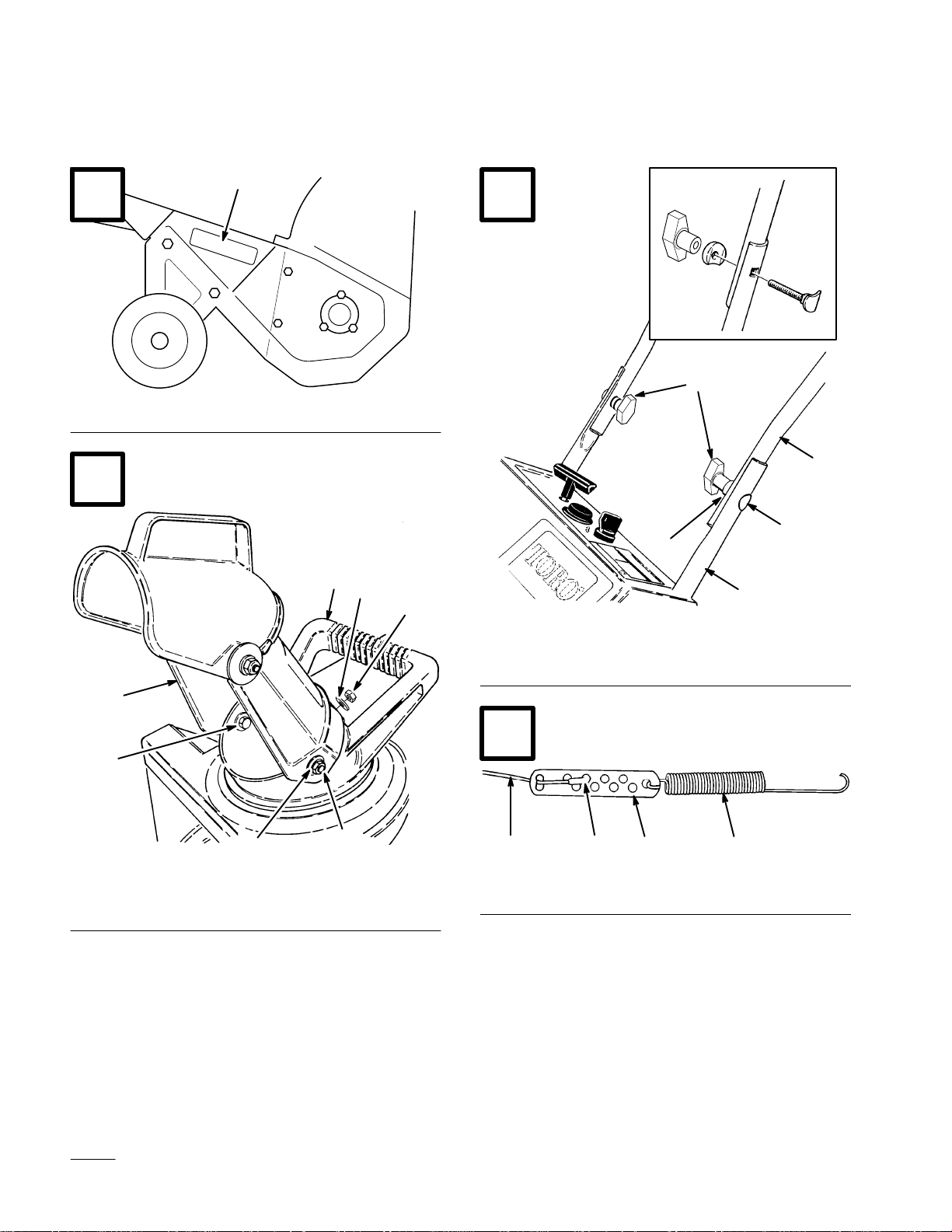
1. Model
2
1
3
and serial number decal
2121
4
2
3
5
2
4
5
1.
Lower handle
2.
Upper handle
3.
Oval head bolt
4. Knob
5.
1
Curved washers
m–4022
4
1.
Discharge chute
2.
Chute handle
3.
Hex bolt
i
4
4. Washer
5. Locknut
5
m-3371
EThe Toro Company – 1998
All Rights Reserved
1. Spring
2.
Cable adjuster
43 21
3. Cable
4.
Z fitting
Printed in USA
897
Page 3
1 235
5
5
6
1. Loop
2.
Control cable
3.
Spring cover
6
1
1/16–1/8”
4
1
4.
Control bar bracket
5. T
op hole
6.
Bottom hole
2
7
3
2
m-3993
3
4
1.
Key switch
2. Primer
3.
Recoil start
4.
Choke lever
8
5.
Elec. start button*
6.
Cord connection*
*
ELEC. START MODEL
2
3
6
m–3992
1
1.
Add oil to small amount of
gasoline
2.
Install cap and shake can
to mix
3.
Add remaining amount of
gasoline
111
1.
Chute handle
2.
Chute deflector handle
3.
Deflector mounting nuts
m-3370
ii
Page 4
3
2
9 10
1
1
1.
Discharge chute
2.
Discharge chute handle
11
921
3. Handle
m–3994
1. W
ear indicator hole
4
8
2
5
1
4
1
3
1
7
1
1. Torx screw
2. Capscrew
iii
3. Locknut
4.
Blade support
6
5.
Drive belt cover
6.
Thick layer
7.
Thin layer
8. W
ear indicator hole
929
Page 5
12
14
2
1
1
1. Scraper 2. W
ear indicator groove
13
1
2
1. Scraper 2. Screws
923
924
1.
Self-tapping screws
15
5
4
1
2
925
2. Capscrew
, nut, washer
3
2
6
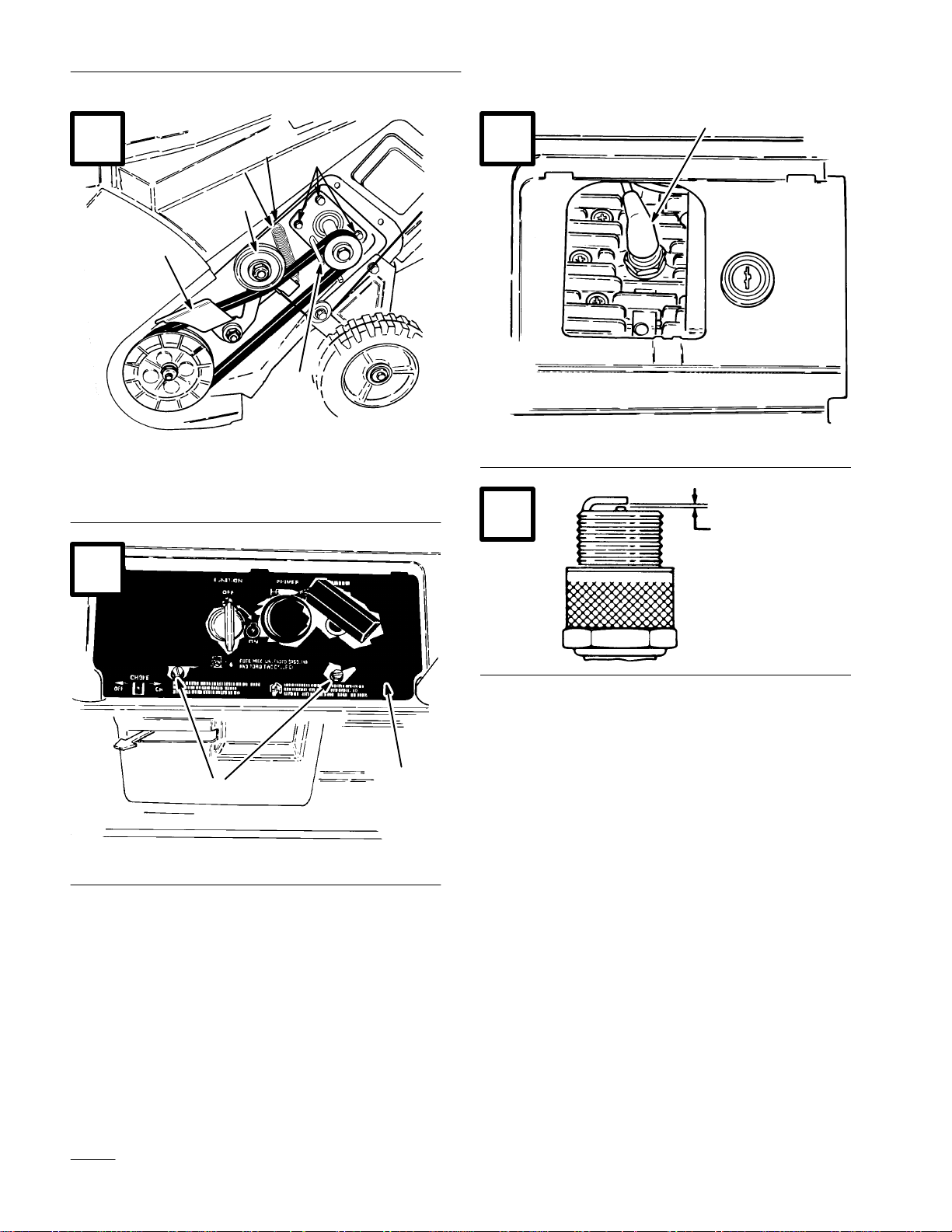
1.
Rotor pulley
2.
Drive pulley
3.
Idler pulley
1
4.
Drive belt
5.
Brake arm
6.
Idler pivot nut
m–4014
iv
Page 6
16
1
4
3
2
18
1
5
6
1.
Idler pulley
2.
Engine mounting nuts (3
of 4 shown)
3.
Idler spring
17
1.
Control panel
4. Hole
5.
Brake arm
6.
Belt guide
m–4015
1.
Spark plug wire
19
0.030”
918
(.76 mm)
110
2
2. Screws
1
917
v
Page 7

Contents
Page
Introduction 1.
Safety 2
Assembly 8
Before Starting 9
Operation 10
Maintenance 12
Storage 15
. . . . . . . . . . . . . . . . . . . . . . . . . . . . . . . . .
Before Operating 2
While Operating 2
Maintaining Snowthrower 3
Sound Pressure Level 4
Vibration Level 4
Symbol Glossary4. . . . . . . . . . . . . . . . . . . .
Install Discharge Chute (Fig. 2) 8
Install Handle (Fig. 3) 8
Install Control Cable 8
Mix Gasoline and Oil (Fig. 6) 9
Starting/Stopping Engine (Fig. 7) 10
Operating Tips (Fig. 8) 11
Folding Snowthrower (Fig. 9) 12
Adjusting Control Bar 12
Draining Gasoline 13
Replacing Rotor Blades (Fig. 10-11) 13
Replacing Scraper (Fig. 12-13) 14
Replacing Drive Belt (Fig. 14-16) 14
Replacing Spark Plug (Fig. 17-19) 14
Adjusting Carburetor 15
. . . . . . . . . . . . . . . . . . . . . . . . . . .
. . . . . . . . . . . . . . . . . . . .
. . . . . . . . . . . . . . . . . . . . .
. . . . . . . . . . . . .
. . . . . . . . . . . . . . . . .
. . . . . . . . . . . . . . . . . . . . .
. . . . . . . . . . . . . . . . . . . . . . . . . . . . . .
. . . . . . . . .
. . . . . . . . . . . . . . . .
. . . . . . . . . . . . . . . . .
. . . . . . . . . . . . . . . . . . . . . . . . . .
. . . . . . . . . .
. . . . . . . . . . . . . . . . . . . . . . . . . . . . . .
. . . . . . .
. . . . . . . . . . . . . . . .
. . . . . . . . . .
. . . . . . . . . . . . . . . . . . . . . . . . . . . .
. . . . . . . . . . . . . . . .
. . . . . . . . . . . . . . . . . . .
. . . . .
. . . . . . . . .
. . . . . . .
. . . . . .
. . . . . . . . . . . . . . . . .
. . . . . . . . . . . . . . . . . . . . . . . . . . . . . . . .
Whenever you contact your Authorized Service
Dealer or the factory, always know the model and
serial numbers of your product. These numbers will
help the Service Dealer or Service Representative
provide exact information about your specific
product. You will find the model and serial number
decal located in a unique place on the product as
shown in Figure 1.
For your convenience, write the product model and
serial numbers in the space below.
Model No:
Serial No.
Read this manual carefully to learn how to operate
and maintain your product correctly. Reading this
manual will help you and others avoid personal injury
and damage to the product. Although Toro designs,
produces and markets safe, state-of-the-art products,
you are responsible for using the product properly
and safely. You are also responsible for training
persons who you allow to use the product about safe
operation.
The Toro warning system in this manual identifies
potential hazards and has special safety messages that
help you and others avoid personal injury, even death.
DANGER, WARNING and CAUTION are signal
words used to identify the level of hazard. However,
regardless of the hazard, be extremely careful.
Introduction
Thank you for purchasing a Toro product.
All of us at Toro want you to be completely satisfied
with your new product, so feel free to contact your
local Authorized Service Dealer for help with service,
genuine Toro parts, or other information you may
require.
DANGER signals an extreme hazard that will cause
serious injury or death if the recommended
precautions are not followed.
WARNING signals a hazard that may cause serious
injury or death if the recommended precautions are
not followed.
CAUTION signals a hazard that may cause minor or
moderate injury if the recommended precautions are
not followed.
GB–1
Page 8

Two other words are also used to highlight
information. “Important” calls attention to special
mechanical information and “Note” emphasizes
general information worthy of special attention.
4. Inspect area thoroughly where snowthrower will
be used. Remove doormats, sleds, boards, sticks,
wire, and any other foreign objects which might
be picked up and thrown by the snowthrower.
The left and right side of the machine is determined
by standing behind the handle in the normal
operator’s position.
Safety
T
o ensur
to gain knowledge of the product, it is essential
that you or any other operator of the snowthrower
read and understand the contents of this manual
before the motor is ever started. Pay particular
attention to the safety alert symbol
means CAUTION, W
“personal safety instruction.” Read and
understand the instruction because it has to do
with safety. Failure to comply with instruction
may result in personal injury.
This snowthrower is designed and tested to offer safe
and effective service, provided it is operated in strict
accordance with the following Safety Instructions.
Failure to comply with the following instructions
MA
e maximum safety, best performance, and
which
ARNING OR DANGER —
Y RESUL
T IN PERSONAL INJUR
Y.
5. Keep all shields and safety devices in place. If a
shield, safety device, or decal is illegible or
damaged, repair or replace it before beginning
operation. Also, tighten any loose nuts, bolts,
knobs or screws.
6. Wear adequate winter clothing and rubber boots
that will ensure proper footing on slippery
surfaces. Do not wear loose fitting clothing that
could possibly get caught in moving parts.
7. Always wear safety glasses or eye shields during
operation or while performing an adjustment or
repair to protect eyes from foreign objects that
may be thrown from the machine.
8. Because fuel is highly flammable, handle it
carefully.
HANDLING GASOLINE.
A. Use an approved fuel container.
B. Fill fuel tank outdoors with extreme care,
C.
DO NOT SMOKE WHILE
not indoors.
NEVER ADD FUEL T
THAT IS RUNNING OR HOT.
O AN ENGINE
Before
1. Read and understand the contents of this manual
2. Never allow children to operate the
3. Keep everyone, especially children and pets,
GB–2
Operating
carefully before operating the snowthrower. Be
thoroughly familiar with all controls and proper
use of the equipment. Know how to stop the
snowthrower and disengage the controls quickly.
snowthrower. Adults should operate the
snowthrower only after reading this manual.
away from the snowthrower and area of
operation.
D. Replace gas cap securely on fuel container
and gas tank, and wipe up any spilled
gasoline before starting engine.
9. Allow engine to warm up outdoors before
operating.
10. Engines produce carbon monoxide gas, which is
an odorless, deadly poison; therefore, do not run
engine indoors or in an enclosed area.
While
11. Use only a CE compliant extension cord for use
Operating
with the electric start model. Do not plug the
extension cord into outlet while standing in
Page 9

water or when hands are wet. Do not use cord if
gasoline has been spilled. If extension cord is
damaged, replace immediately.
12. Never direct discharge toward or operate
snowthrower near bystanders, glass enclosures,
automobiles and trucks, window wells, or a
drop–off. Never allow anyone in front of
snowthrower.
22. If a foreign object is hit or snowthrower vibrates
abnormally, stop engine by turning key to OFF,
disconnect spark plug wire, disconnect the cord
on electric start units, and wait for all moving
parts to stop. Check snowthrower immediately
for possible damage, an obstruction, or loose
parts. Vibration is generally a sign of trouble.
Repair any damage before operating
snowthrower again.
13. Operate the snowthrower only when there is
good visibility or light.
14. Always maintain secure footing and balance and
keep a firm grip on the handle. Walk; never run.
Exercise caution to avoid slipping or falling.
15. Be attentive when using the snowthrower, and
stay alert for holes in the terrain and other
hidden hazards.
16. STA
17. Never clear snow off steep slopes or across the
18. DO NOT USE SNOWTHROWER ON A
19. Do not overload the snowthrower by clearing
Y BEHIND THE HANDLES AND
AWAY FROM DISCHARGE OPENING
WHILE OPERA
SNOWTHROWER. Keep face, hands, feet, and
any other part of your body or clothing away
from concealed, moving or rotating parts.
face of slopes. Exercise extreme caution when
changing direction on slopes.
ROOF.
snow at too fast a rate.
TING THE
23. Before adjusting, cleaning, repairing or
inspecting the snowthrower, or before
unclogging the discharge chute or auger housing,
stop engine by turning key to OFF and wait for
all moving parts to stop. Do not make any
adjustments while engine is running. Disconnect
the spark plug wire and keep the wire away from
plug to prevent accidental starting.
24.
WHENEVER YOU LEA
OPERA
BY TURNING KEY T
KEY FROM SWITCH IF UNIT WILL BE
UNATTENDED.
25. Let snowthrower run for a few minutes after
clearing snow so moving parts do not freeze.
26. Remove key from switch when snowthrower is
transported or not in use.
27. Always drain gasoline from snowthrower fuel
tank before transporting in a car trunk or vehicle;
refer to Draining Gasoline, page 13. Gasoline
and its fumes are highly flammable, explosive,
and dangerous if inhaled.
TING POSITION, ST
VE THE
O OFF
OP ENGINE
. REMOVE
20. Never operate the machine at high transport
speeds on slippery surfaces.
21.
Use extr
snowthrower on walks or roads. It is not
recommended that snowthrower be used on
gravel or crushed rock drives. Stay alert for
hidden hazards or traffic. Refer to Operation,
page 11, item 5 for correct operating procedure.
eme caution when crossing or operating
Maintaining
28. REMOVE KEY FROM SWITCH when storing
snowthrower. Store key in a memorable place.
29. Never store snowthrower with fuel in fuel tank
inside a building where ignition sources such as
an open flame, sparks, hot water and space
heaters, and clothes dryers are present. Allow
engine to cool before storing. Never store
Snowthrower
GB–3
Page 10

snowthrower in house (living area) or basement
because gasoline and fumes are highly
flammable, explosive, and dangerous if inhaled.
30. Always refer to Operator’s Manual for important
details if snowthrower is to be stored for an
extended period.
35. To ensure optimum performance and safety,
purchase genuine TORO replacement parts and
accessories to keep your TORO all TORO.
NEVER USE “WILL FIT” REPLACEMENT
PAR
TS AND ACCESSORIES.
31. Perform only those maintenance instructions
described in this manual.
32. Remove key from switch and spark plug wire
from the spark plug before performing
maintenance procedures to prevent the
possibility of accidental starting. Ensure that the
spark plug wire cannot accidentally touch the
spark plug.
33. If major repairs are ever needed, contact your
local Authorized TORO Service Dealer for
assistance.
34. Keep snowthrower in safe operating condition
by keeping nuts, bolts, and screws tight. Check
all fasteners frequently to ensure they are tight.
Symbol
Glossary
Sound
This unit has a sound pressure at the operator’s ear of
90 dBA, based on measurements of identical
machines per Directive 81/1051/EEC.
Sound
This unit has a sound power level of 103 LwA, based
on measurements of identical machines per Directive
79/113/EEC.
Vibration
This unit has a maximum hand-arm vibration level of
11.4 m/s@, based on measurements of identical
machines per EN 1033.
Pressure Level
Power Level
Level
Safety
symbol within triangle
indicates a hazard
Safety alert symbol
Read operator
manual
GB–4
alert triangle —
’s
Do not open or
remove safety shields
while engine is
running
Stay a safe distance
from the machine
Stay a safe distance
from the machine –
single stage
snowthrower
Page 11

Consult technical
manual for proper
service procedures
Shut off engine and
remove key before
performing
maintenance or repair
work
Shut off engine and
remove key before
leaving operator
position – single
stage snowthrower
Shut off engine and
remove key before
leaving operator
position – two stage
snowthrower
Stay a safe distance
from the machine –
two stage
snowthrower
Thrown or flying
objects — Whole body
exposure
Electrical shock –
electrocution
Cutting or
entanglement of foot –
rotating auger
Severing of fingers or
hand – impeller blade
Hot surfaces – burns
to fingers or hands
Caustic liquids –
chemical burns to
fingers or hands
Electric start
Machine loss of
control – uphill slope
Machine loss of
control – downhill
slope
GB–5
Page 12

Do not tip battery T
raction drive
Keep dry
Machine travel
direction – forward
Machine travel
direction – rearward
On/start Choke
Snowthrower collector
auger
Engage
Disengage
Off/stop
Fast Neutral
Engine speed
(Throttle)
GB–6
Page 13

Slow
Decreasing/Increasing Lock
Snowthrower collector
auger
Engine start
Engine stop
Snowthrower chute
direction
Primer (start aid)
Unlock
Lever operation
Lever operation
Unleaded fuel
Primer operation
Throttle operation Cutting of foot
Cutting of fingers or
hand
GB–7
Page 14

PowerShift operation
Belt routing
Assembly
Note: Determine left and right sides of
snowthrower by standing in the normal
operating position.
Note: Figures referenced in this section are
contained in the front of this
document.
Install
1. Position holes on sides of discharge chute over
2.
Discharge Chute (Fig. 2)
hex bolts on sides of chute handle. Secure
discharge chute onto hex bolts with (2) washers
and (2) locknuts. While holding hex bolt heads
with a wrench (7/16), tighten locknuts securely.
Rotate dischar
position. Secure rear of discharge chute with a
washer and locknut.
ge chute to the completely upright
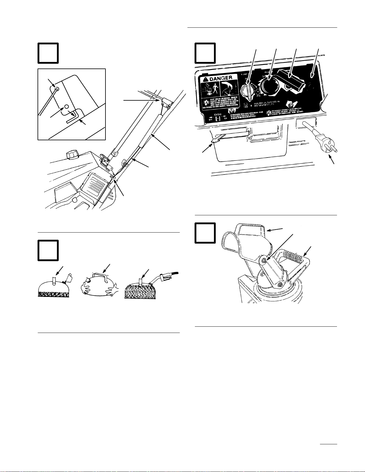
2. Secure upper handle to lower handles using oval
head bolts, curved washers, and knobs. Position
knobs and curved washers on inside of handle
and
TIGHTEN KNOBS SECUREL
prevent them from loosening.
Note: Make sure the oval head bolts and
curved washers are aligned correctly as
shown in Figure 3 to prevent knobs
from loosening.
Install
1. Route control cable through loop on left side of
2. Hook spring to round hole at end of cable
3. Route cable through elongated hole in cable
Control Cable
snowthrower.
adjuster (Fig. 4).
adjuster. Insert Z fitting on end of cable into 3rd
hole on cable adjuster (Fig. 4).
Y to
Install
1. Position ends of upper handle on inside of lower
GB–8
Handle (Fig. 3)
handles and align holes. Ensure that the handle is
positioned so that the control bar is on the upper
side of the handle.
4. Slide spring cover over spring and cable adjuster.
Push spring end through hole at end of spring
cover (Fig. 5).
5. Hook spring into top hole of control bar bracket
(Fig. 5).
6. Move control bar back toward handle until slack
in cable is removed. The gap between the control
bar bracket and handle should be approximately
Page 15

1/16”-1/8”. See insert, Figure 5. If an adjustment
is required, refer to Adjusting Control Bar,
page 12.
Note: The control cable must always have
slack in it when in the disengaged
position.
Before
Starting
only the quantity of gasoline that can be used in 30
days. Use of lead-free gasoline results in fewer
combustion chamber deposits and longer spark plug
life. Use of premium grade fuel is not necessary.
1. APPROVED OIL—For simplicity and best
engine performance, mix the contents of one 5.2
ounce bottle of Toro 50:1 Two–Cycle Oil with
two gallons of fresh, unleaded regular gasoline.
You can also use Toro “Easy–Mix” Two–Cycle
Oil (3.2 ounce bottle mixed one per gallon of
gasoline; 40:1 ratio) in this Toro two–cycle
engine. Leaded regular gasoline may be used if
unleaded regular is not available.
POTENTIAL
HAZARD
• In certain conditions gasoline is extremely
flammable and highly explosive.
WHAT CAN HAPPEN
• A fire or explosion from gasoline can burn
you and others and cause property damage.
HOW TO AV
OID THE HAZARD
• Use a funnel and fill the fuel tank outdoors,
in an open area, when the engine is cold.
Wipe up any gasoline that spills.
• Do not fill the fuel tank completely full.
Add gasoline to the fuel tank until the level
is 1/4” to 1/2” (6 mm to 13 mm) below the
bottom of the filler neck. This empty space
in the tank allows gasoline to expand.
• Never smoke when handling gasoline, and
stay away from an open flame or where
gasoline fumes may be ignited by a spark.
• Store gasoline in an approved container
and keep it out of the reach of children.
• Never buy more than a 30-day supply of
gasoline.
Note: Figures referenced in this section are
contained in the front of this
document.
Mix
Gasoline and Oil (Fig. 6)
Use clean, fresh lead-free gasoline, including
oxygenated or reformulated gasoline, with an octane
rating of 85 or higher. To ensure freshness, purchase
Toro Two–Cycle Oil is specially formulated to
provide superior lubrication, make starting easy,
and prolong engine life. If Toro T
is not available, mix two gallons of gasoline and
5.2 ounces of another high grade two–cycle oil
that has the NMMA or BIA–TCW certification
printed on the label.
NEVER USE AUTOMOTIVE OIL (i.e. SAE
30, 10W30 etc.), TWO–CYCLE OIL THAT IS
NOT CERTIFIED NMMA/BIA–TCW, OR THE
WRONG MIX RA
ENGINE CAN BE DAMAGED, AND IT
WOULD NOT BE COVERED BY THE TORO
WARRANTY.
2. Mixing Gasoline and Oil—Pour a half gallon of
gasoline into an approved gasoline container and
add the correct amount of two–cycle oil. Install
cap on gasoline container and shake the
container to mix oil and gas thoroughly. Remove
cap and add remaining amount of gasoline.
Toro also recommends that Toro
Stabilizer/Conditioner be used regularly in all
Toro gasoline powered products during operation
and storage seasons. Toro Stabilizer/Conditioner
cleans the engine during operation and prevents
gum–like varnish deposits from forming in the
engine during periods of storage.
Note: A fuel stabilizer/conditioner is most
effective when mixed with fresh
gasoline.
TIO BECAUSE THE
wo–Cycle Oil
GB–9
Page 16

IMPORTANT
GASOLINE CONT
GASOHOL CONT
10% ETHANOL, PREMIUM GASOLINE,
OR WHITE GAS BECAUSE ENGINE
FUEL SYSTEM DAMAGE COULD
RESULT.
DO NOT USE FUEL ADDITIVES OTHER
THAN THOSE MANUF
FUEL ST
STORAGE SUCH AS TORO’S
ST
ABILIZER/CONDITIONER OR A
SIMILAR PRODUCT
ST
ABILIZER/CONDITIONER IS A
PETROLEUM DISTILLA
CONDITIONER/ST
DOES NOT RECOMMEND ST
WITH AN ALCOHOL BASE SUCH AS
ETHANOL, METHANOL OR ISOPROPYL.
ADDITIVES SHOULD NOT BE USED T
TRY TO ENHANCE THE POWER OR
PERFORMANCE OF MACHINE.
: NEVER USE METHANOL
AINING METHANOL
AINING MORE THAN
ACTURED FOR
ABILIZA
TION DURING
. TORO’S
TE BASED
ABILIZER. T
ABILIZERS
,
,
ORO
O
Starting/Stopping
Engine
(Fig. 7)
1. CONTROLS—Key switch, primer, electric start
button (if applicable), and recoil starter are
located on the control panel. The choke lever is
just below the lower left corner of the control
panel.
2. Turn key to ON and move choke lever to ON
(far right position).
3. Cover hole in center of primer with thumb and
push primer twice slowly (1 to 2 seconds per
prime) for temperatures above 0_F (–18_C).
Push primer slowly three times for temperatures
below 0_F (–18_C).
ENGINE HAS BEEN RUNNING AND IS
HOT.
Note: When starting engine for first time or
after running out of fuel, more priming
may be required to start engine.
DO NOT PRIME IF THE
Note: Do not mix gasoline and oil in the
product fuel tank. Oil that is at room
temperature mixes easier and more
thoroughly than cold oil.
50:1
GAS/OIL Mixing Chart
U.S. GALLON
Gasoline Oil
Operation
Note: Figures referenced in this section are
contained in the front of this
document.
4. STARTING
A. RECOIL STARTING—Hold snowthrower
with one hand and pull recoil starter
vigorously with other hand. If engine does
not start after three pulls, push primer once
more and pull recoil starter vigorously
again.
B. ELECTRIC STARTING—Connect
extension cord to snowthrower and standard
household power outlet. Push starter button.
When engine starts, disconnect extension
cord from snowthrower and outlet.
IMPORTANT: Excessive running of the
electric starter could damage the starter due
to overheating. If you are having difficulty
starting the engine, ONL
STAR
TING PROCEDURE TWICE. Run the
electric starter no more than 10 times at
intervals of 5 seconds ON, 5 seconds OFF. If
engine does not start after this first attempt,
wait more than 40 minutes to allow starter to
cool before trying to run starter again. Before
Y TR
Y THIS
GB–10
Page 17

repeating engine starting procedure, check
that ignition key switch is ON, and make sure
there is fresh fuel in fuel tank. If engine still
will not start after a second attempt, bring the
snowthrower to an Authorized Toro Service
Dealer for servicing.
IMPORTANT: Do not leave the electric
starter cord connected to the power outlet
when storing the snowthrower. It should only
be connected to the power outlet during the
starting procedure. If you leave it connected
to the power outlet during storage, a power
surge could start the snowthrower when no
one is in attendance.
5. When engine starts, move choke lever to middle
position after a few seconds of running time.
After engine has warmed up, move choke lever
to OFF (far left) position.
6. TO START/STOP ROTOR—To start the rotor,
squeeze the control bar to the handle. When the
control bar handle is released, the rotor blades
stop, but the engine continues to run.
7. TO STOP ENGINE—Release the control bar to
stop the rotor, turn key to OFF, and wait for all
moving parts to stop before leaving operator’s
position.
Operating Tips (Fig. 8)
1. ADJUSTING DISCHARGE CHUTE—Move
the chute handle left and right to adjust the
direction of the snow stream. Rotate the chute
deflector handle on top of the discharge chute
forward and backward to adjust the height of the
snow stream. Do not overtighten the chute
deflector mounting nuts so excessive force is
required to adjust the deflector.
2. SELF–PROPELLING ACTION—The
snowthrower clears down to the ground and
propels itself forward when tilted slightly
forward so rotor blades strike the ground. The
wheels do not have to touch the ground in order
to self-propel. The further you tilt the handle
forward, the faster the snowthrower self-propels.
However, depth of snow affects forward speed.
Always overlap each swath and discharge
downwind when possible.
Note: If snowthrower is tilted too far
forward, it will self-propel at a rapid
rate and snow will spray back at the
feet of the operator. Reduce lift on
handle slightly to self-propel at a
moderate rate.
3. Keep the area to be cleared free of stones, toys,
or other foreign objects which may be picked up
and thrown by the rotor blades. Such items could
be covered by snowfall and, therefore, unnoticed
until struck by the rotor blades. Always be sure
to keep all people and pets away from area of
operation to prevent possibility of being hit by
thrown objects.
4. ON STEPS OR CUTTING THROUGH
DRIFTS—It is recommended that operator stand
on right side of snowthrower and hold it by
upper handle and chute handle (standing on left
side may expose operator to engine exhaust).
Use a side–to–side sweeping motion to clear
snow.
5. It is not recommended that snowthrower be used
on gravel or crushed rock driveways or walks.
Should you find it necessary to clear snow from
crushed rock or gravel, push down on handle to
raise rotor blades clear of loose material that
could be thrown by the blades and push unit
forward.
6. In some snow and cold weather conditions, some
controls and moving parts may freeze solid. DO
NOT USE EXCESSIVE FORCE WHEN
TR
YING T
CONTROLS. When any control or part
becomes hard to operate, start the engine and let
it run for a few minutes. If control or part still
will not move with moderate force, stop engine,
remove ice or thaw out snowthrower.
O OPERA
TE FROZEN
GB–11
Page 18

POTENTIAL HAZARD
• Gasoline and its fumes are highly
flammable, explosive, and dangerous if
inhaled.
WHAT CAN HAPPEN
• If gasoline contacts a flame or is inhaled,
serious personal injury can occur.
HOW TO AV
OID THE HAZARD
• Never warm up snowthrower with fuel in
tank inside a building where open flame or
sparks ar
•
Never stor
area), basement or anywhere open flame is
present.
•
Always r
fuel tank before transporting in a closed
car trunk or vehicle; refer to Draining
Gasoline, page 13.
e present.
e snowthrower in house (living
emove gasoline from snowthrower
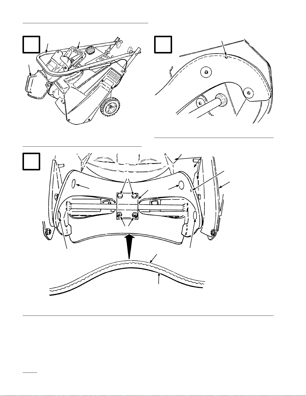
3. Loosen knobs on handle and fold handle down
over unit, ensuring that you do not kink the
control cable.
4. Carry unit by discharge chute handle.
5. Be sure to tighten all knobs SECURELY
unfolding handle and chute.
after
Maintenance
Keep snowthrower in safe operating condition by
cleaning the unit. Check and tighten any loose nuts,
bolts, knobs, and screws. The scraper, drive belt, rotor
blades, and spark plug should be checked once a year.
Note: Figures referenced in this section are
contained in the front of this
document.
Adjusting
Control Bar
7. AFTER CLEARING SNOW—Let engine run
for a few minutes so ice does not freeze moving
parts solid. After engine is shut off, wipe ice and
snow off entire unit.
IMPORTANT: ST
IN OPERA
WHEELS OR HANG ON A W
HANDLE. TIPPING OR ST
FORW
CAUSE HARD ST
Folding
The CCR POWERLITE folds compactly for easy
transporting or storage. To fold up snowthrower,
follow these instructions:
1. Remove locknut and washer from rear of
discharge chute.
2. Fold chute down. Reinstall locknut and washer
tightly onto bolt at rear of discharge chute handle
to prevent losing them.
TING POSITION ON ITS
ARD ONT
Snowthrower (Fig. 9)
ORE SNOWTHROWER
ALL BY ITS
ORING UNIT
O FRONT HOUSING MAY
ARTING.
Periodically check control bar for proper adjustment.
1. Turn key switch to OFF.
2. CHECK ADJUSTMENT (Fig. 5)—Move
control bar back toward handle until slack in
cable is removed. Gap between control bar
bracket and handle should be approximately
1/16”–1/8”. If cable is too loose or too tight,
proceed to step 3 for adjustment procedure.
Note: The control cable must always have
slack in it when in the disengaged
position.
3. Unhook spring end from the top hole in control
bar bracket (Fig. 5).
4. Slide spring cover off spring and cable adjuster.
5. Unhook Z fitting from cable adjuster and
reposition Z fitting in a higher or lower hole on
adjuster to obtain proper gap of 1/16”–1/8”
between control bar bracket and handle (Fig. 4).
(Positioning cable end in a lower hole decreases
gap; positioning cable end in a higher hole
increases gap.)
GB–12
Page 19

6. Install spring cover over cable adjuster and
spring.
7. Hook spring into top hole of control bar bracket
(Fig. 5).
8. After extended use, the drive belt may wear and
proper belt tension may not be maintained.
Improper belt tension causes belt slippage and
decreases the snowthrower
a heavy load. Belt slippage may occur after 2–3
seasons of normal usage (10–15 hours). If drive
belt slips (continuous squealing noise) under
heavy load, increase belt tension by
repositioning spring end in bottom hole in
control bar bracket (Fig. 5).
Readjust cable (see steps 2–3).
’s performance under
Replacing
(Fig. 10-1
Before each snow season, inspect rotor blades for
wear. When blade edge has worn to the wear indicator
hole (Fig. 10), the blades must be replaced to ensure
proper performance and prevent damage to underside
of snowthrower. Always replace both blades at the
same time.
Note: Whenever rotor blades are replaced,
1. Stop engine. Remove key from switch. Pull wire
off spark plug.
Rotor Blades
1)
scraper should also be replaced to
ensure proper snowthrower operation
and performance.
IMPORTANT: Unnecessary use of forward or
bottom adjusting hole in control bar bracket
reduces drive belt life. Occasional belt slippage
(squealing) may occur in extremely wet
conditions due to moisture in drive system. To
remove moisture, start rotor and operate under
no load for 30 seconds. Once moisture is
removed, belt should not slip.
Draining
1. Stop engine. Remove key from switch.
2. Remove cap from fuel tank and use a pump type
syphon to drain fuel into a clean, approved fuel
container.
3. After fuel is drained, start engine and let it run
until all fuel is consumed and engine stops.
Repeat the starting procedure two more times to
ensure all fuel is removed from the engine.
Note: This is the only procedure
Gasoline
recommended for draining fuel because
it allows all fuel to be removed from
fuel tank.
2. REMOVING BLADE (Fig. 11)–Remove (4)
Torx screws (Bit No. T27), (2) capscrews, and
(6) locknuts securing blade to rotor shaft
assembly.
3. Slide the blade out from between the blade
supports (Fig. 11).
4. INSTALLING NEW BLADE–The rotor blades
are made of laminated rubber. Examine the edge
of a blade to see the difference in layer thickness
(Fig. 11).
Both blades must be installed with the thick
layer on the inside of the curve, and the wear
indicator holes must be on the drive belt cover
side (Fig. 11). If one of the blades is installed
with the thick layer on the outside of the curve
and the other blade installed with the thick layer
on the inside of the curve, the blades will be
unbalanced, causing the snowthrower to “hop”
or “bounce.”
5. Insert new blade between blade supports. Secure
center of blade to blade supports with (2)
capscrews and (2) locknuts. Position screw heads
on thick layer side of blade. Curve blade and
secure it with remaining (4) Torx screws and
locknuts (position screw heads on thick layer
side of blade). Tighten all screws and nuts
securely.
GB–13
Page 20

6. Repeat steps 1–5 to replace other blade.
B. Pull belt out at the bottom of the rotor
pulley and remove it from the pulley.
Replacing
Before each season, inspect scraper for wear. When
wear indicator groove is worn away (Fig. 12), replace
scraper to prevent damage to underside of
snowthrower.
1. Stop engine. Remove key from switch. Pull wire
off spark plug.
2. Tip snowthrower forward onto front housing.
3. Remove (3) screws holding scraper in place
(Fig. 13). Remove scraper.
4. Secure new scraper to housing with (3) screws.
Replacing
Scraper (Fig. 12-13)
Drive Belt
(Fig. 14-16)
After extended use, drive belt may wear and require
replacement. If drive belt continues to slip under a
heavy load or the rotor does not turn, check to see if
belt is severely worn.
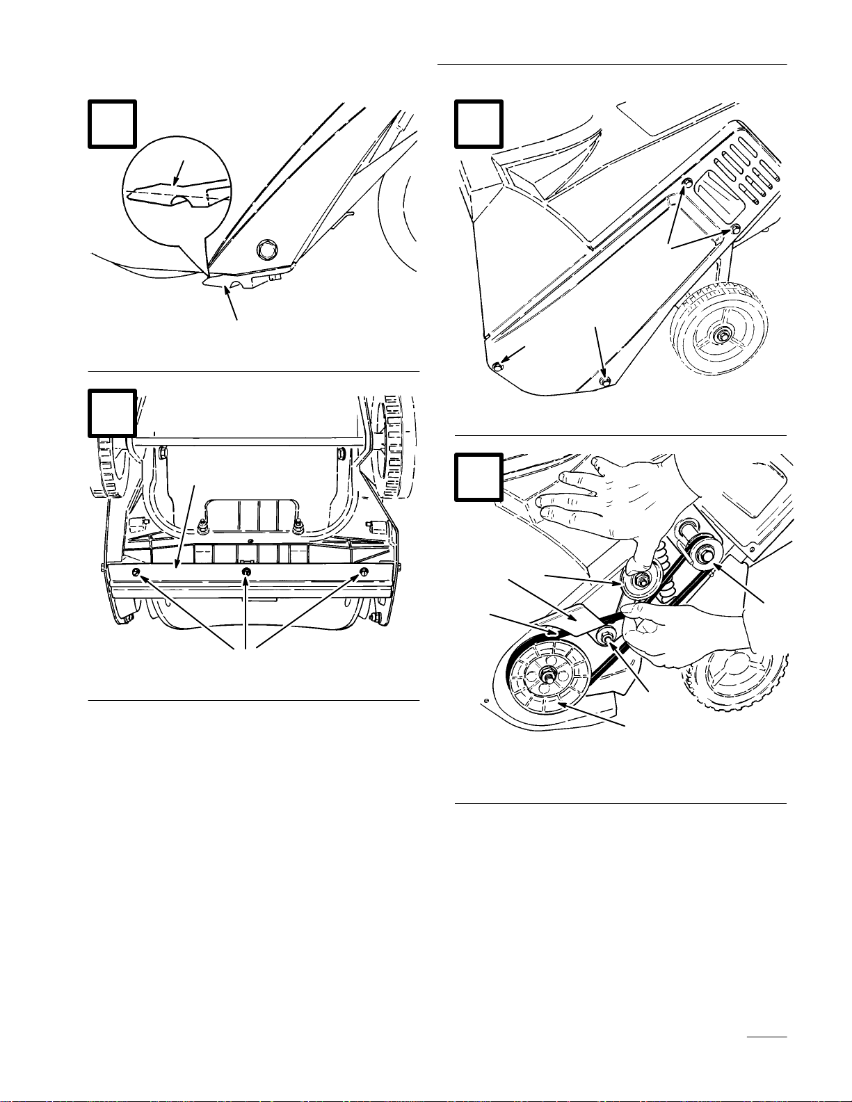
C. Push down on the idler pulley to release the
brake arm and pull the belt from behind the
brake arm.
D. Slide the belt off of the drive pulley.
5. INSTALLING BELT (Fig. 16):
A. Loop belt around drive pulley.
B. While holding belt with right hand, slip belt
onto rotor pulley and rotate rotor with left
hand until belt is completely on rotor
pulley.
C. Make sure long end of idler spring is
hooked in housing hole and round end of
spring is hooked in the brake arm.
D. Lift up the brake arm assembly
belt together, and route belt under idler
pulley.
6. Tighten the engine mounting nuts and the idler
pivot nut. Torque to 170 to 200 in–lbs (19.2 to
22.5 N·m)
, squeeze
1. Stop engine. Remove key from switch. Pull wire
off spark plug.
2. Remove (3) self tapping screws, (1) capscrew,
(1) washer, and (1) nut securing left side cover to
snowthrower frame (Fig. 14). Remove cover.
3. Loosen the (4) engine mounting nuts enough to
allow the belt guide to be rotated away from the
drive pulley to remove the belt (Fig. 16).
IMPORTANT: Do not remove the nuts or the
engine will fall loose into the snowthrower. If
you accidentally remove the nuts, contact
your Authorized Toro Service Dealer.
4. REMOVING BELT (Fig. 15):
A. Loosen idler pivot nut.
7. Reinstall left side cover. T
securely, but DO NOT OVERTIGHTEN.
Replacing
Spark Plug
ighten fasteners
(Fig. 17-19)
Check spark plug yearly or every 100 operating
hours. If electrodes in center of plug are dark or have
deteriorated, install a new plug. Use a Champion
RCJ8Y spark plug or equivalent and set gap at .030”
(.76 mm).
1. REMOVE CONTROL PANEL
(Fig. 17)–Remove (2) screws securing control
panel to housing. Remove ignition key and lift
off panel, allowing it to hang on recoil rope.
GB–14
Page 21

2. REMOVE SPARK PLUG (Fig. 18)–Pull wire
off spark plug and remove plug. Examine the
plug and replace if cracked, fouled, or dirty. DO
NOT SANDBLAST
SP
ARK PLUG BECAUSE DIR
RELEASE AND F
CAUSING ENGINE DAMAGE.
, SCRAPE, OR CLEAN
T MA
Y
ALL INT
O CYLINDER
2. CYLINDER/PISTON CARE—Slowly pull
recoil starter until resistance is felt due to
compression pressure, then stop. Release starter
tension slowly to prevent engine from reversing
due to compression pressure. This position
closes both the intake and exhaust ports which
prevents corrosion of the cylinder bore.
3. INSTALL SPARK PLUG–Set air gap (Fig. 19)
between electrodes at .030” (.76 mm). Install
plug and tighten to 15 ft–lb (20.4 Nm). If torque
wrench is not used, tighten plug firmly with
wrench by hand; DO NOT OVERTIGHTEN.
Push wire onto spark plug and reinstall control
panel.
Adjusting
The carburetor has been factory set, and no
adjustment is required.
Carburetor
Storage
1. FUEL SYSTEM PREPARATION–
Note: A fuel stabilizer/conditioner is most
effective when mixed with fresh
gasoline.
3. TIGHTEN FASTENERS AND
CLEAN—Tighten screws, bolts, knobs and nuts
if necessary
Clean unit thoroughly.
4. ST
ORE SNOWTHROWER—Cover
snowthrower and store in a clean, dry place out
of the reach of children.
SNOWTHROWER IN HOUSE (LIVING
AREA) OR BASEMENT WHERE
IGNITION SOURCES MA
SUCH AS HOT WATER AND SPACE
HEA
LIKE
ARE HIGHL
EXPLOSIVE, AND DANGEROUS IF
INHALED.
in any enclosure.
. Repair or replace damaged parts.
NEVER ST
Y BE PRESENT
TERS, CLOTHES DR
BECAUSE GASOLINE AND FUMES
Y FLAMMABLE,
Allow engine to cool before storing
YERS, AND THE
ORE
• Add Toro Stabilizer/Conditioner to the fuel tank
(one ounce per gallon of fuel).
• Run engine for ten minutes to distribute
conditioned fuel through fuel system.
• Stop engine, allow it to cool, and drain fuel tank
or run engine until it stops.
• Restart the engine again and run it until it stops.
• Either choke or prime the engine, restart it a
third time and run engine until it will not restart.
• Dispose of fuel properly. Recycle per local
codes.
• DO NOT store ST
days.
ABILIZED gasoline over 90
GB–15
Page 22

Page 23

Page 24

 Loading...