

Page 1
Form No. 3326-370 Rev A
622 Power Throw
Snowthrower
Model No. 38064—220000001 and Up
Operator’s Manual
Domestic English (EN)
Page 2
Warning
The engine exhaust from this product contains
chemicals known to the State of California to cause
cancer, birth defects, or other reproductive harm.
Important This engine is not equipped with a spark
arrester muffler. It is a violation of California Public
Resource Code Section 4442 to use or operate this engine
on any forest-covered, brush-covered or grass-covered
land. Other states or federal areas may have similar laws.
This spark ignition system complies with Canadian
ICES-002.
Ce système d’allumage par étincelle de véhicule est
conforme à la norme NMB-002 du Canada.
The enclosed Engine Owner’s Manual is supplied for
information regarding The U.S. Environmental
Protection Agency (EPA) and the California Emission
Control Regulation of emission systems, maintenance
and warranty.
Keep this engine Owner’s Manual with your unit.
Should this engine Owner’s Manual become damaged
or illegible, replace immediately. Replacements may be
ordered through the engine manufacturer.
Contents
Page
Introduction 2. . . . . . . . . . . . . . . . . . . . . . . . . . . . . . . . .
Safety 3. . . . . . . . . . . . . . . . . . . . . . . . . . . . . . . . . . . . . .
Safe Operating Practices 3. . . . . . . . . . . . . . . . . . . .
Toro Snowthrower Safety 4. . . . . . . . . . . . . . . . . . .
Safety and Instruction Decals 6. . . . . . . . . . . . . . . . .
Assembly 8. . . . . . . . . . . . . . . . . . . . . . . . . . . . . . . . . . .
Loose Parts 8. . . . . . . . . . . . . . . . . . . . . . . . . . . . . . .
Installing the Handle Assembly 8. . . . . . . . . . . . . . .
Installing the Speed Selector Rod 9. . . . . . . . . . . . .
Installing the Traction Rod 9. . . . . . . . . . . . . . . . . . .
Installing the Auger/Impeller Drive Control
Linkage 10. . . . . . . . . . . . . . . . . . . . . . . . . . . . . . . .
Installing the Chute Control Rod 11. . . . . . . . . . . . . .
Securing the Chute Deflector 11. . . . . . . . . . . . . . . . .
Before Starting 12. . . . . . . . . . . . . . . . . . . . . . . . . . . . . . .
Filling the Engine Crankcase with Oil 12. . . . . . . . . .
Filling the Fuel Tank with Gasoline 12. . . . . . . . . . . .
Checking the Tire Pressure 13. . . . . . . . . . . . . . . . . .
Reviewing the Maintenance Schedule 13. . . . . . . . . .
Operation 13. . . . . . . . . . . . . . . . . . . . . . . . . . . . . . . . . . .
Operating Controls 13. . . . . . . . . . . . . . . . . . . . . . . . .
Removing the Carburetor Heater Box 14. . . . . . . . . .
2001 by The Toro Company
8111 Lyndale Avenue South
Bloomington, MN 55420-1196
Page
Installing the Carburetor Heater Box 15. . . . . . . . . . .
Starting the Engine 15. . . . . . . . . . . . . . . . . . . . . . . . .
Stopping the Engine 16. . . . . . . . . . . . . . . . . . . . . . . .
Freewheeling or Self-propel Drive 16. . . . . . . . . . . .
Snowthrowing Tips 16. . . . . . . . . . . . . . . . . . . . . . . .
Maintenance 17. . . . . . . . . . . . . . . . . . . . . . . . . . . . . . . . .
Recommended Maintenance Schedule 17. . . . . . . . .
Checking the Engine Oil Level 18. . . . . . . . . . . . . . .
Checking the Auger Gearbox Grease 18. . . . . . . . . . .
Adjusting the Skids and the Scraper 19. . . . . . . . . . .
Adjusting the Speed Selector 20. . . . . . . . . . . . . . . . .
Adjusting the Traction Drive Belt 20. . . . . . . . . . . . .
Replacing the Traction Drive Belt 21. . . . . . . . . . . . .
Adjusting the Auger/Impeller Drive Belt 22. . . . . . . .
Replacing the Auger/Impeller Drive Belt 22. . . . . . .
Changing the Engine Oil 22. . . . . . . . . . . . . . . . . . . .
Lubricating the Snowthrower 23. . . . . . . . . . . . . . . . .
Replacing the Spark Plug 23. . . . . . . . . . . . . . . . . . . .
Emptying the Fuel Tank 24. . . . . . . . . . . . . . . . . . . . .
Storage 24. . . . . . . . . . . . . . . . . . . . . . . . . . . . . . . . . . . . .
Preparing the Fuel System 24. . . . . . . . . . . . . . . . . . .
Preparing the Engine 24. . . . . . . . . . . . . . . . . . . . . . .
Preparing the Snowthrower 24. . . . . . . . . . . . . . . . . .
Accessories 25. . . . . . . . . . . . . . . . . . . . . . . . . . . . . . . . .
Troubleshooting 25. . . . . . . . . . . . . . . . . . . . . . . . . . . . . .
The Toro Total Coverage Guarantee 28. . . . . . . . . . . . . .
Introduction
Read this manual carefully to learn how to operate and
maintain your product properly. The information in this
manual can help you and others avoid injury and product
damage. Although Toro designs and produces safe
products, you are responsible for operating the product
properly and safely.
Whenever you need service, genuine Toro parts, or
additional information, contact an Authorized Service
Dealer or Toro Customer Service and have the model and
serial numbers of your product ready. Figure 1 illustrates
the location of the model and serial numbers on the
product.
1
m–2592
Figure 1
1. Location of the model and serial numbers
All Rights Reserved
Printed in the USA
2
Page 3

Write the product model and serial numbers in the space
below:
Model No.
Training
• Read the operator’s manual carefully. Be thoroughly
familiar with the controls and the proper use of the
equipment. Know how to stop the unit and disengage
the controls quickly.
Serial No.
This manual identifies potential hazards and has special
safety messages that help you and others avoid personal
injury and even death. Danger, Warning, and Caution are
signal words used to identify the level of hazard. However,
regardless of the hazard, be extremely careful.
Danger signals an extreme hazard that will cause serious
injury or death if you do not follow the recommended
precautions.
Warning signals a hazard that may cause serious injury or
death if you do not follow the recommended precautions.
Caution signals a hazard that may cause minor or moderate
injury if you do not follow the recommended precautions.
This manual uses two other words to highlight information.
Important calls attention to special mechanical
information and Note: emphasizes general information
worthy of special attention.
Safety
This two-stage snowthrower meets or exceeds the B71.3
specifications of the American National Standards
Institute in effect at the time of production.
To ensure maximum safety and best performance, and
to gain knowledge of the product, it is essential that you
and any other operator of the snowthrower read and
understand the contents of this manual before the
engine is ever started.
• Never allow children to operate the snowthrower. Never
allow adults to operate the snowthrower without proper
instruction.
• Keep the area of operation clear of all persons
(particularly small children) and pets.
• Exercise caution to avoid slipping or falling, especially
when operating the snowthrower in reverse.
Preparation
• Thoroughly inspect the area where you will use the
snowthrower. Remove all doormats, sleds, boards,
wires, and other foreign objects.
• Disengage all clutches and shift the snowthrower into
neutral before starting the engine.
• Do not operate the snowthrower without wearing
adequate winter garments. Wear footwear that will
improve your footing on slippery surfaces.
• Handle fuel with care; it is highly flammable.
– Use an approved fuel container.
– Never add fuel to a running or hot engine.
– Fill the fuel tank outdoors with extreme care. Never
fill the fuel tank indoors.
– Replace the fuel tank cap securely and wipe up any
spilled fuel.
• Use only the power cord supplied with the snowthrower
and a receptacle appropriate for use with the power cord
for electric-starting motors.
This is the safety alert symbol. It is used to alert you
to potential personal injury hazards. Obey all safety
messages that follow this symbol to avoid possible
injury or death.
Improperly using or maintaining this snowthrower
could result in injury or death. To reduce this potential,
comply with the following safety instructions.
Safe Operating Practices
The following instructions have been adapted from the
ANSI/OPEI B71.3–1995 standard and the ISO 8437:1989
standard. Information or terminology specific to Toro
snowthrowers is enclosed in parenthesis.
• Adjust the auger housing height to clear gravel or
crushed rock surface.
• Never attempt to make any adjustments while the
engine is running, except where specifically
recommended by Toro.
• Let the engine and the snowthrower adjust to the
outdoor temperature before starting to clear snow.
• Operating any powered machine can result in foreign
objects being thrown into the eyes. Always wear safety
glasses or eye shields while operating, adjusting, or
repairing the snowthrower.
3
Page 4

Operation
• Do not put hands or feet near or under rotating parts.
Keep clear of the discharge opening at all times.
• Never operate the snowthrower without good visibility
or light. Always be sure of your footing, and keep a
firm hold on the handle. Walk; never run.
• Exercise extreme caution when operating on or crossing
gravel drives, walks, or roads. Stay alert for hidden
hazards or traffic.
• After striking a foreign object, stop the engine, remove
the wire from the spark plug, thoroughly inspect the
snowthrower for any damage, and repair the damage
before operating the snowthrower.
• If the unit should start to vibrate abnormally, stop the
engine and check immediately for the cause. Vibration
is generally a warning of trouble.
• Stop the engine whenever you leave the operating
position, before unclogging the auger/impeller housing
or discharge chute, and when making any repairs,
adjustments, or inspections.
• When cleaning, repairing, or inspecting, make certain
that the auger/impeller and all moving parts have
stopped. Disconnect the spark-plug wire, and keep the
wire away from the spark plug to prevent someone from
accidentally starting the engine.
• Do not run the engine indoors, except when starting it
and for moving the snowthrower in or out of the
building. Open the outside doors; exhaust fumes are
dangerous.
• Do not clear snow across the face of slopes. Exercise
extreme caution when changing direction on slopes. Do
not attempt to clear steep slopes.
• Never operate the snowthrower without proper guards
or other safety devices in place.
• Never operate the snowthrower near glass enclosures,
automobiles, window wells, and drop-offs without
properly adjusting the snow discharge angle. Keep
children and pets away.
• Do not overload the machine capacity by attempting to
clear snow at too fast a rate.
• Never operate the machine at high transport speeds on
slippery surfaces. Look behind and use care when
moving in reverse.
• Never direct the discharge at bystanders or allow
anyone in front of the unit.
• Disengage the power to the auger/impeller when the
snowthrower is being transported or when not in use.
• Use only attachments and accessories approved by
Toro, such as wheel weights, counterweights, and cabs.
(Contact your Authorized Service Dealer for
accessories available for your snowthrower.)
Maintenance and Storage
• Check all fasteners at frequent intervals for proper
tightness to be sure that the equipment is in safe
working condition.
• Never store the machine with fuel in the fuel tank inside
a building where ignition sources are present, such as
hot water and space heaters and clothes dryers. Allow
the engine to cool before storing in any enclosure.
• Always refer to this operator’s manual for important
details if the snowthrower is to be stored for an
extended period.
• Maintain or replace safety and instruction labels when
necessary.
• Run the engine run for a few minutes after clearing the
snow to prevent the auger/impeller from freezing.
Toro Snowthrower Safety
The following list contains safety information specific to
Toro products or other safety information that you must
know.
• Rotating auger/impeller can cut off or injure fingers or
hands. Stay behind the handles and away from the
discharge opening while operating the snowthrower.
Keep your face, hands, feet, and any other part of your
body or clothing away from moving or rotating parts.
• Before adjusting, cleaning, repairing, and inspecting the
snowthrower, and before unclogging the dischar ge
chute, stop the engine, remove the key, and wait for all
moving parts to stop. Also, disconnect the wire from the
spark plug and keep it away from the spark plug to
prevent someone from accidentally starting the engine.
• Use a stick, not your hands, to remove obstructions
from the discharge chute.
• Before leaving the operating position, stop the engine,
remove the key, and wait for all moving parts to stop.
• Do not wear loose-fitting clothing that could get caught
in moving parts.
• If a shield, safety device, or decal is damaged, illegible,
or lost, repair or replace it before beginning operation.
Also, tighten any loose fasteners.
• Do not smoke while handling gasoline.
• When operating the snowthrower on slopes, use the
lower gear. For Power Shift
rear wheel position.
snowthrowers, use the
4
Page 5
• Do not use the snowthrower on a roof.
• Do not touch the engine while it is running or soon after
it has stopped because the engine may be hot enough to
cause a burn. Do not add oil or check the oil level in the
crankcase while the engine is running.
• Perform only those maintenance instructions described
in this manual. Before performing any maintenance,
service, or adjustment, stop the engine, remove the key
and disconnect the wire from the spark plug. Keeping
the wire away from the spark plug to prevent someone
from accidentally starting the engine. If major repairs
are ever needed, contact your Authorized Service
Dealer.
• Do not change the governor settings on the engine.
• When storing the snowthrower for more than 30 days,
drain the fuel from the fuel tank to prevent a potential
hazard. Store fuel in an approved fuel container.
Remove the key from the ignition switch before storing
the snowthrower.
• To ensure the best performance and safety, purchase
only genuine Toro replacement parts and accessories.
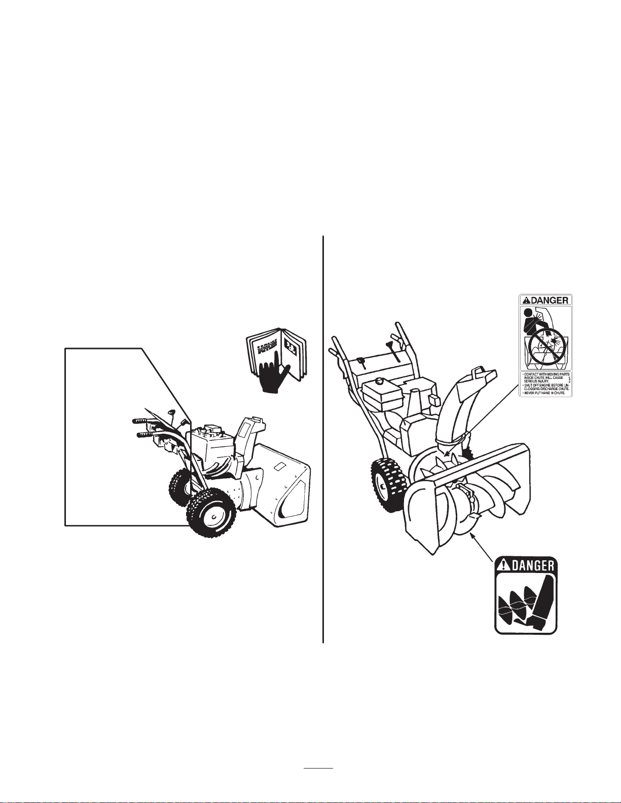
Before Operating
Read and understand the contents of this manual
before operating the snowthrower. Become familiar
with all controls and know how to stop the engine
quickly.
Operator's
Position
472
Caution: Improper use may result
in loss of fingers, hands, or feet.
There is a highspeed
impeller within two inches
of the opening.
1508
The lowspeed auger
has a moving pinch
point close to the
opening.
5
Page 6
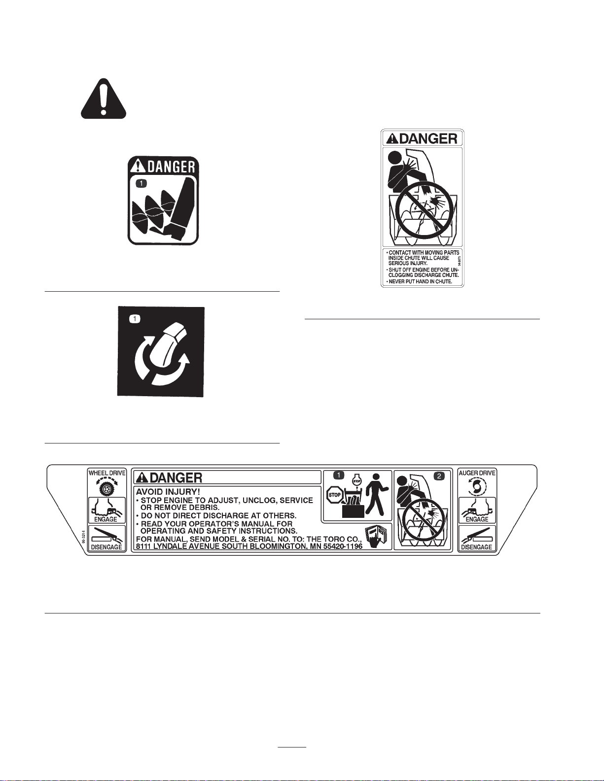
Safety and Instruction Decals
Safety decals and instructions are easily visible to the operator and are located near any area
of potential danger. Replace any decal that is damaged or lost.
53-7670
1. Cutting/dismemberment hazard in auger
94-8079
63-3510
2. Chute direction control
99-3214
1. Stop the engine before leaving the machine
2. Contact with the moving parts within the chute will cause serious injury; never put your hand into the chute
6
Page 7
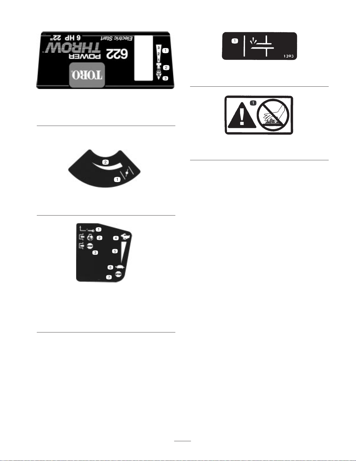
100-3333
1. Forward drive speed
settings
2. Speed selector
3. Reverse drive speed
setting
Tecumseh Part No. 34418
1. Choke 2. Increasing scale
Tecumseh Part No. 36501
1. Primer
Tecumseh Part No. 37119
1. Warning—hot surface; do not touch
Tecumseh Part No. 35063
1. Key ignition
2. Engage to start the
engine
3. Disengage to stop the
engine
4. Fast
5. Increasing scale
6. Slow
7. Stop the engine
7
Page 8

Assembly
g
Note: Determine the left and right sides of the machine from the normal operating position.
Loose Parts
DESCRIPTION QTY. USE
Handle assembly 1
Bolts 4
Curved washers 4
Flange nut 1
Speed selector rod 1
Installing the handle assembly
Cotter pin 1
Flat washer 1
Flange locknut 1 Installing the traction rod
Clevis pin
Cotter pin
Chute control rod assembly (Rod and bracket,
worm gear, and bracket)
Bolt, pyramidal washer, and locknut 1 Installing the chute control rod
Bolt 1
Locknut 1
Carriage bolt
Rubber washer
Friction plate
Large flat washer
Curved washer
Locknut
Ignition key 1 Starting and stopping the engine
1
1
1
1
1
1
1
1
1
Installing the speed selector rod
Installing the auger/impeller drive control
linkage
Securing the chute deflector
Power cord 1 Starting the engine
Installing the Handle Assembly
1. Remove the tie straps that secure the control rods to the
handle assembly.
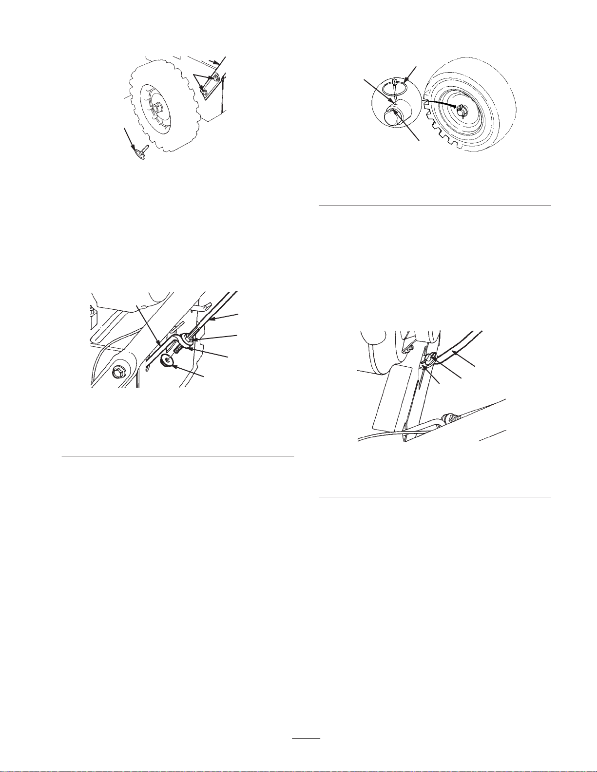
2. Remove the axle pins from both wheels (Fig. 2) and
slide the wheels outward on the axle approximately one
inch (2.5 centimeters).
8
Page 9
3
2
1
3
1
653
Figure 2
1. Axle pin (2)
2. Cap screws and curved
washers (4)
3. Handle assembly
3. Thread a flange nut (not the flange locknut) with the
flange down onto the traction rod attached to the left
side of the handle assembly (Fig. 3).
1
2
3
4
5
654
Figure 3
1. Lower traction rod
2. Traction rod
3. Flange nut
4. Loop
5. Flange locknut
4. Position the left side of the handle assembly against the
side of the snowthrower and insert the end of the
traction rod through the loop in the lower traction rod
(Fig. 3).
5. Align the holes in the left side of the handle assembly
with the holes in the left side plate, and secure the
handle with two cap screws and curved washers until
they are finger tight (Fig. 2).
Note: The concave side of the curved washer goes
against the outside of the handle.
6. Align the holes in the right side of the handle assembly
with the holes in the right side plate, and secure the
handle with two cap screws and curved washers until
they are finger tight.
7. Ensure that the handles are at the same height, then
tighten the handle fasteners securely.
8. Slide the wheels inward and insert each axle pin
through the hole in each wheel hub and through the
inner hole of the axle (Fig. 4).
2
473
Figure 4
1. Inner axle hole and wheel
hub
2. Outer axle hole
3. Axle pin
Note: To use tire chains (optional), install the axle pins
through the outer axle holes.
Installing the Speed Selector
Rod
1. Pull the speed selector arm (Fig. 5) to the most outward
position.
3
2
1
648
Figure 5
1. Speed selector arm
2. Flat washer and cotter pin
3. Speed selector rod
2. Move the speed selector (Fig. 13) on the control panel
to the R (Reverse) position.
3. Install the speed selector rod into the selector arm, add a
flat washer on the selector rod, and secure it with a
cotter pin (Fig. 5).
Installing the Traction Rod
1. Thread the flange locknut (flange side up) onto the
bottom of the traction control rod, below the loop in the
lower traction rod (Fig. 3).
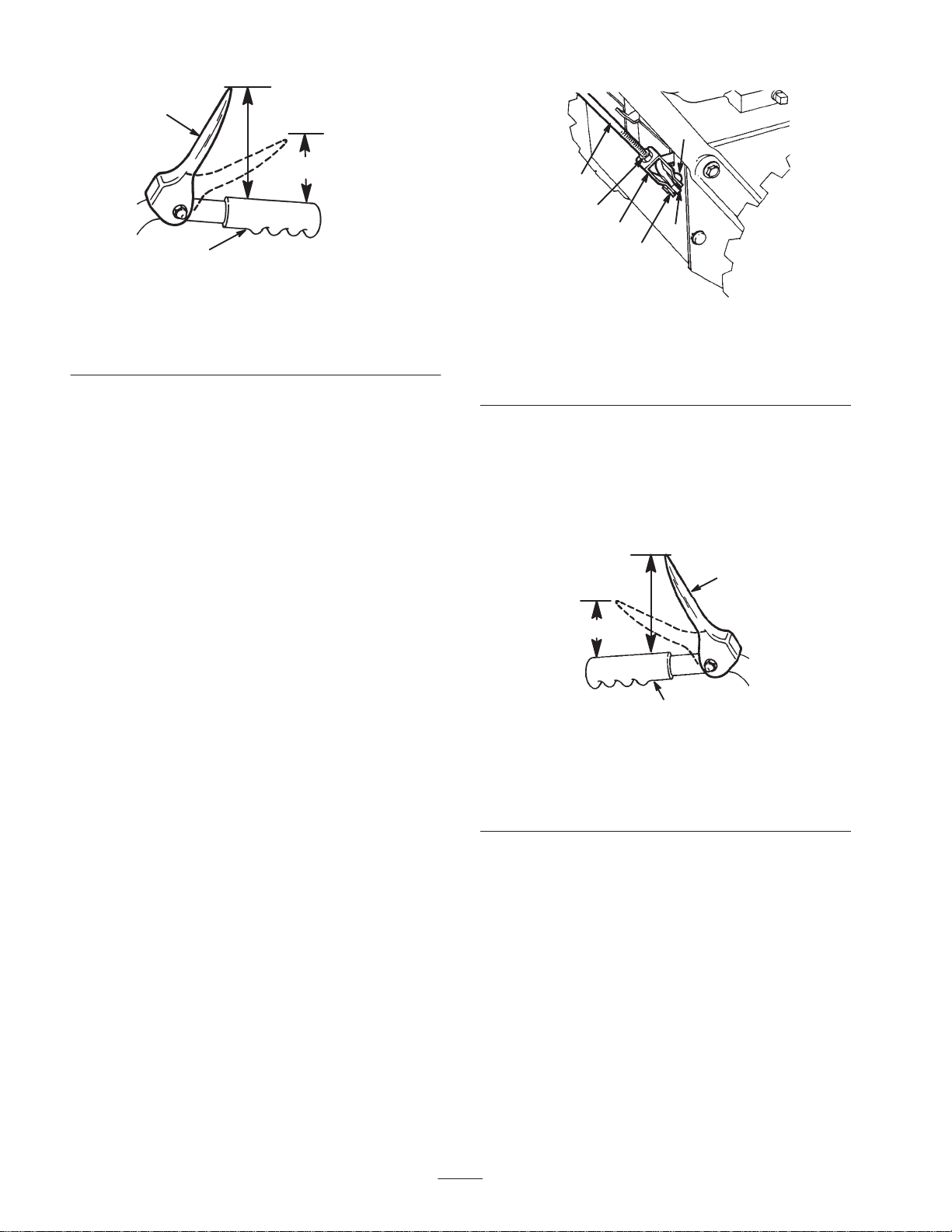
2. Adjust the two flange nuts up or down on the traction
rod until the distance between the top of the handgrip
and the bottom of the traction control lever is
approximately 4-3/8 inches (11 centimeters) as shown
in Figure 6.
9
Page 10
1
3
5
4
2
665
Figure 6
1. Traction control lever
2. Handgrip
3. 4-3/8 inches
(11centimeters)
4. One to two inches (2.5 to
5.0 centimeters)
3. Tighten the two flange nuts until they are finger tight.
4. Move the speed selector (Fig. 13) into third gear.
Note: If the speed selector does not move into third
gear, adjust the speed selector before continuing. Refer
to Adjusting the Speed Selector on page 20.
5. Slowly pull the snowthrower backward while slowly
pressing the traction control lever toward the handgrip.
Note: The adjustment is correct when the wheels stop
rolling backward and the distance between the top of
the handgrip and the bottom of the traction control lever
is one to two inches (2.5 to 5.0 centimeters) as shown in
Figure 6.
1
2
3
6
649
4
Figure 7
1. Upper control rod
2. Jam nut
3. Clevis
4. Cotter pin
5. Clevis pin
6. Lower control rod
2. Align the holes in the clevis and the lower control rod
and insert the clevis pin (Fig. 7).
3. Check the distance between the top of the handgrip and
the bottom of the auger/impeller drive control lever
(Fig. 8). The distance should be approximately four
inches (ten centimeters).
4
2
1
6. Adjust the two flange nuts, if necessary, to obtain the
proper distance between the top of the handgrip and the
bottom of the traction control lever.
7. Tighten the flange nuts securely.
Installing the Auger/Impeller
Drive Control Linkage
1. Loosen the jam nut above the clevis on the upper
control rod (Fig. 7).
3
665
Figure 8
1. One to two inches (2.5 to
5.0 centimeters)
2. Four inches
(ten centimeters)
3. Handgrip
4. Auger/impeller control
lever
4. Press the auger/impeller drive control lever slowly
toward the handgrip.
Note: The amount of force needed to compress the
lever increases noticeably when you remove the slack
from the auger/impeller drive belt (approximately
one-half of the lever movement). The adjustment is
correct when the force begins to increase and the
distance between the top of the handgrip and the bottom
of the auger/impeller drive control lever is one to two
inches (2.5 to 5.0 centimeters) as shown in Figure 8.
Note: If the force does not noticeably increase, remove
the belt cover (refer to steps 1 and 2 of Replacing the
Auger/Impeller Drive Belt on page 22) and measure
10
Page 11
two inches (five centimeters) above the handgrip at the
point where you remove the slack from the
auger/impeller drive belt.
3. Loosely mount the worm gear and the bracket to the
mounting flange with a bolt, a pyramidal washer, and a
locknut as shown in Figure 10.
5. To adjust the distance:
A. Remove the clevis pin.
B. Loosen the jam nut.
C. Thread the clevis up or down to increase or decrease
the distance between the top of the handgrip and the
bottom of the auger/impeller drive control lever
(Fig. 7).
6. When the adjustment is correct, install the clevis pin
and secure it in place with the cotter pin (Fig. 7).
7. Tighten the jam nut to secure the clevis (Fig. 7).
Installing the Chute Control
Rod
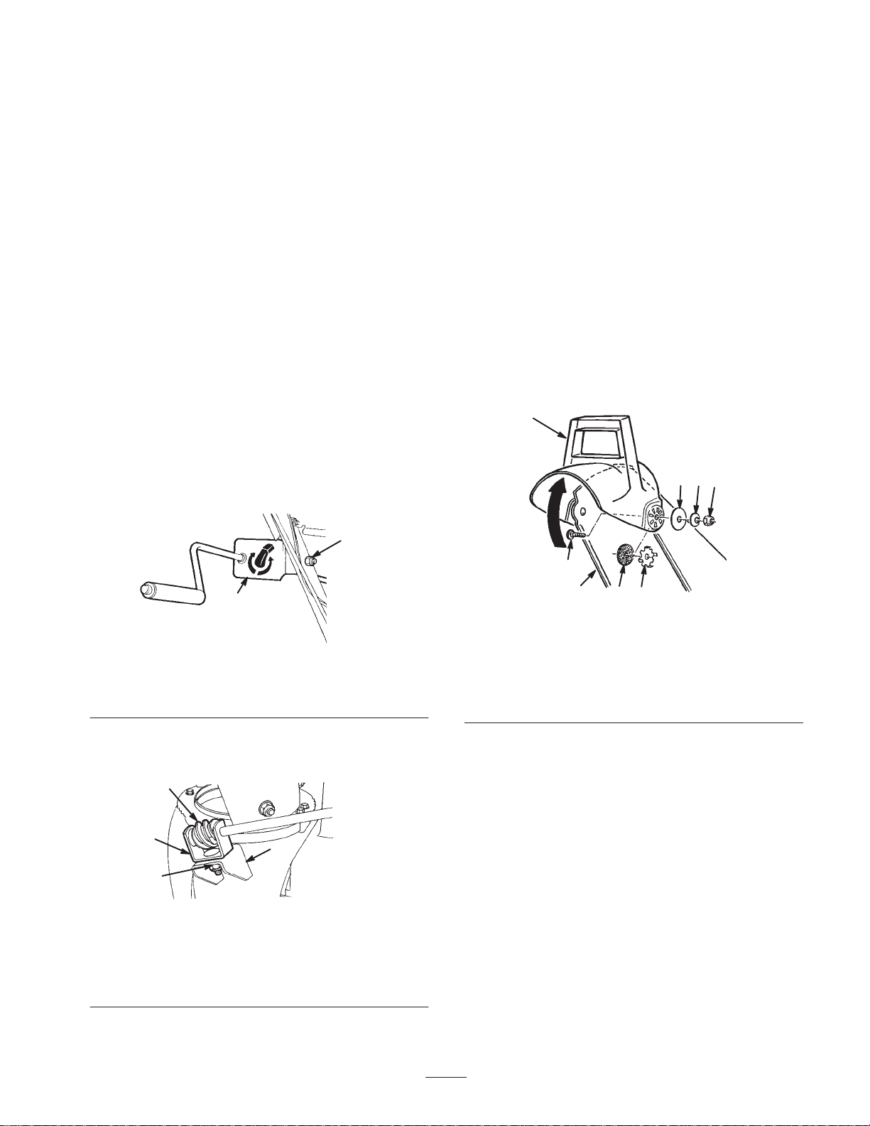
1. Assemble the chute control bracket and rod to the left
side of the handle assembly with the bolt and the
locknut as shown in Figure 9.
Note: Leave the locknut loose.
2
4. Slide the worm gear into the teeth of the chute retaining
ring and tighten the locknut (Fig. 10).
5. Tighten the locknut that secures the chute control
bracket (Fig. 9).
6. Check the operation of the chute control rod, and move
the worm gear slightly outward if it binds.
Securing the Chute Deflector
1. Pivot the deflector upward and back until the deflector
stop passes over the lip on the top of the discharge
chute.
2. Secure the left side of the deflector to the discharge
chute using the parts as shown in Figure 11.
1
7
6
8
1
886
Figure 9
1. Chute control bracket and
rod
2. Bolt and locknut
2. Apply No. 2 general purpose grease to the worm gear
(Fig. 10).
1
2
4
3
658
Figure 10
1. Worm gear
2. Bracket
3. Bolt, pyramidal washer,
and locknut
4. Mounting flange
2
3
4
5
667
Figure 11
1. Deflector
2. Carriage bolt
3. Discharge chute
4. Rubber washer
5. Friction plate
6. Large flat washer
7. Curved washer
8. Locknut
Note: Position the rubber washer and the friction plate
between the discharge chute and the deflector, and
ensure that the friction plate tabs fit into the holes in the
deflector.
Note: The concave side of the curved washers go
against the large flat washers.
3. Tighten the nuts on both sides of the deflector. Do not
overtighten the nuts.
11
Page 12
Before Starting
Filling the Engine Crankcase
with Oil
The engine comes from the factory with only a few ounces
of oil in the crankcase. Before starting the engine, add oil.
The crankcase holds 21 ounces (0.62 liters) of oil; however,
because there is some oil in the crankcase, do not add the
full amount at one time. Use only a high-quality, SAE
5W–30 or SAE 10 weight detergent oil that has the
American Petroleum Institute (API) service classification
SF, SG, SH, or SJ. For extremely cold conditions (below
0°F or –18°C), use 0W–30 weight detergent oil that has the
American Petroleum Institute (API) service classification
SF, SG, SH, or SJ.
To add oil:
1. Move the snowthrower to a level surface to ensure an
accurate oil level reading.
8. If the oil level is below the Add mark on the dipstick,
slowly pour only enough oil into the filler hole to raise
the oil level to the Full mark on the dipstick.
Important Do not overfill the crankcase with oil and
run the engine; engine damage will result. Drain the excess
oil until the oil level on the dipstick reads Full.
9. Insert the dipstick into the filler neck and rotate the cap
clockwise until it is tight.
Filling the Fuel Tank with
Gasoline
For best results, use clean, fresh, lead-free gasoline,
including oxygenated or reformulated gasoline, with an
octane rating of 87 or higher. To ensure freshness, purchase
only the quantity of gasoline that you expect to use in 30
days. Using unleaded gasoline results in fewer combustion
deposits and longer engine life. You may use leaded
gasoline if unleaded gasoline is not available.
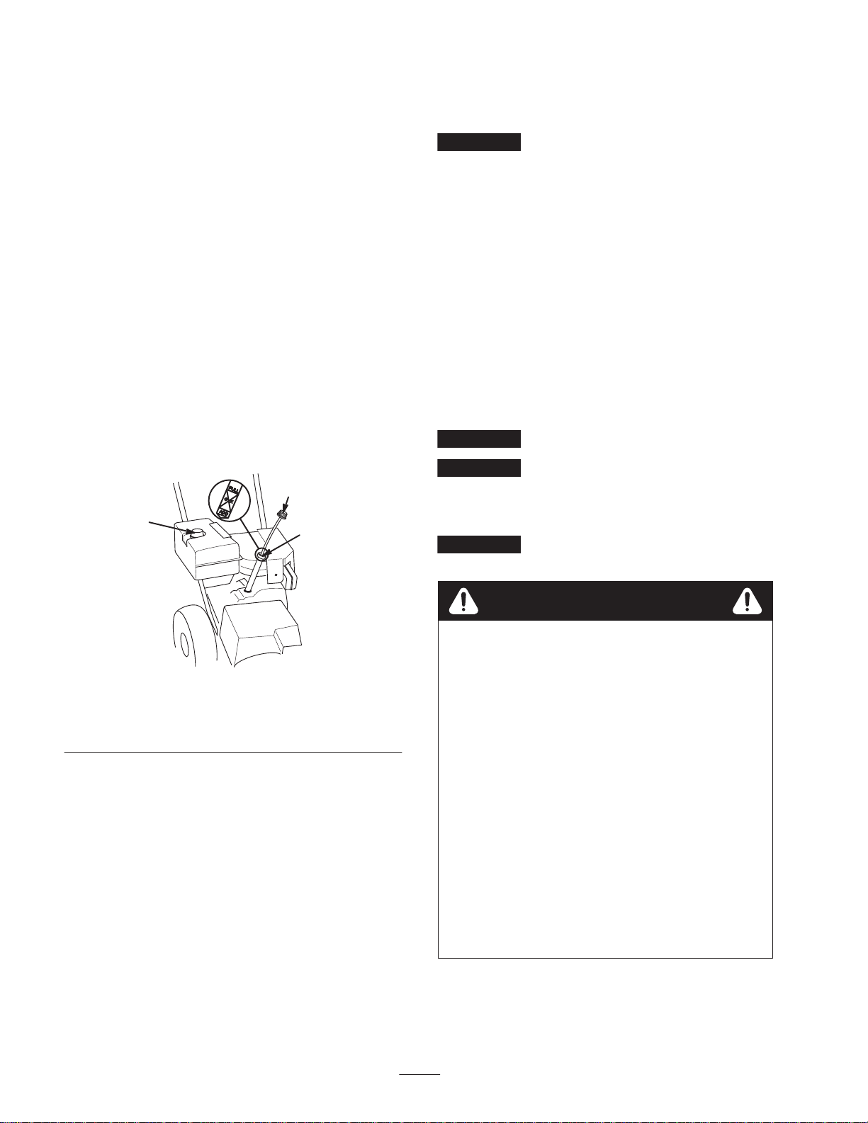
2. Clean around the dipstick (Fig. 12).
2
1
Figure 12
1. Fuel tank cap
2. Dipstick
3. Remove the dipstick by rotating the cap
counterclockwise and pulling it out (Fig. 12).
4. Slowly pour about three-fourths of the crankcase
capacity of oil into the crankcase.
5. Wipe the dipstick clean with a clean cloth.
6. Install the dipstick into the filler neck, then remove it.
Note: To ensure an accurate oil level reading, you must
fully install the dipstick.
7. Read the oil level on the dipstick.
3. Filler hole
3
684
Important Do not add oil to the gasoline.
Important Do not use methanol, gasoline containing
methanol, gasohol containing more than 10% ethanol,
premium gasoline, or white gas. Using these fuels can
damage the engine’s fuel system.
Important Do not use gasoline that is more than 30
days old.
Danger
In certain conditions, gasoline is extremely
flammable and highly explosive. A fire or
explosion from gasoline can burn you and others
and can damage property.
• Fill the fuel tank outdoors, in an open area, and
when the engine is cold. Wipe up any gasoline
that spills.
• Do not fill the fuel tank completely full. Add
gasoline to the fuel tank until the level is 1/4 to
1/2 in. (6 to 13 mm) below the bottom of the
filler neck. This empty space in the tank allows
the gasoline to expand.
• Never smoke when handling gasoline, and stay
away from an open flame or where a spark may
ignite the gasoline fumes.
• Store gasoline in an approved fuel container and
keep it out of the reach of children.
• Never buy more than a 30-day supply of
gasoline.
12
Page 13
Danger
When fueling, under certain circumstances, a
static charge can develop, igniting the gasoline. A
fire or explosion from gasoline can burn you and
others and damage property.
• Always place gasoline containers on the ground
and away from your vehicle before filling.
• Do not fill gasoline containers inside a vehicle or
on a truck or trailer bed because interior
carpets or plastic truck bed liners may insulate
the container and slow the loss of any static
charge.
• When practical, remove gasoline-powered
equipment from the truck or trailer and refuel
the equipment with its wheels on the ground.
• If this is not possible, then refuel such
equipment on a truck or trailer from a portable
container, not from a gasoline dispenser nozzle.
• If you must use a gasoline dispenser nozzle, keep
the nozzle in contact with the rim of the fuel
tank or container opening at all times until
fueling is complete.
Reviewing the Maintenance
Schedule
Review the Recommended Maintenance Schedule on
page 17. You may need to perform one or more additional
procedures before or soon after you begin operating the
snowthrower.
Operation
Note: Determine the left and right sides of the machine
from the normal operating position.
Operating Controls
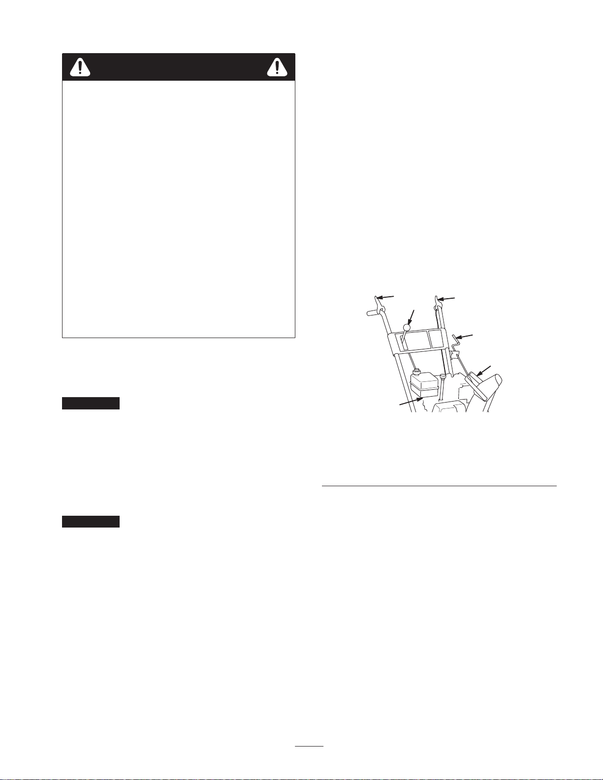
• Auger/Impeller Drive Control Lever (Fig. 13)—To
engage both the auger and impeller, press the lever
against the right handgrip. To disengage, release the
lever.
1
3
2
4
Use a fuel stabilizer/conditioner regularly during operation
and storage. A stabilizer/conditioner cleans the engine
during operation and prevents gum-like varnish deposits
from forming in the engine during periods of storage.
Important Do not use fuel additives other than a fuel
stabilizer/conditioner. Do not use fuel stabilizers with an
alcohol base such as ethanol, methanol, or isopropanol.
1. Clean around the fuel tank cap (Fig. 12).
2. Remove the fuel tank cap.
3. Fill the fuel tank with unleaded to within 1/4 to 1/2 inch
(6 to 13 millimeters) from the top of the tank. Do not
fill into the filler neck.
Important Do not fill the fuel tank more than 1/4 inch
(6 millimeters) from the top of the tank because the
gasoline must have room to expand.
4. Install the fuel tank cap and wipe up any spilled
gasoline.
Checking the Tire Pressure
Check the pressure of the tires because they are
overinflated at the factory for shipping. Reduce the
pressure equally in both tires to between 12 and 15 psi
(82 and 103 kPa).
5
6
Figure 13
1. Auger/impeller drive
control lever
2. Traction control lever
3. Speed selector
• Traction Control Lever (Fig. 13)—To engage the
traction (wheel drive), press the lever against the left
handgrip. To stop the traction, release the lever.
• Speed Selector (Fig. 13)—This control has four
positions: three forward speeds and one reverse. To
change speeds, move the speed selector to the desired
position. The lever locks in a notch at each speed
selection.
Note: Before shifting gears into or out of reverse, you
must release the traction control lever. You may shift
between any of the forward speeds without releasing the
traction control lever.
• Discharge Chute Control (Fig. 13)—Rotate the
discharge chute control clockwise to move the
discharge chute to the left; counterclockwise to move
the chute to the right.
4. Discharge chute control
5. Chute deflector handle
6. Fuel shutoff valve
879
13
Page 14
• Chute Deflector Handle (Fig. 13)—Move the deflector
handle forward to move the snow stream down; move it
rearward to move the snow stream up.
1
2
• Fuel Shutoff Valve (Fig. 13)—Close the valve by
rotating clockwise. Open the valve by rotating it
counterclockwise. Close the valve when you do not use
the snowthrower.
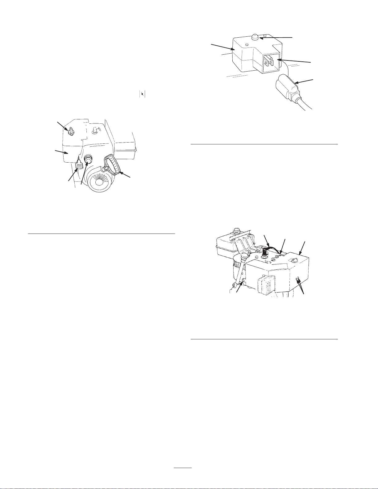
• Choke (Fig. 14)—Move the choke to the (Full)
position to start a cold engine. As engine warms up,
gradually move the choke to the Off position.
1
2
5
3
4
725
Figure 14
1. Choke
2. Ignition switch
3. Throttle
4. Primer
5. Recoil starter
• Ignition Switch (Fig. 14)—Insert the key before
starting the engine. To stop the engine, remove the key.
3
4
m–4516
Figure 15
1. Electric starter
2. Starter button
3. Receptacle
4. Power cord
• Power Cord (Fig. 15)—Connect the power cord to the
electric starter and to an electrical outlet when starting
the engine.
Removing the Carburetor
Heater Box
If you operate the engine when the air temperature is above
40F (4C), remove the carburetor heater box (Fig. 16).
1
2
3
• Throttle (Fig. 14)—Move the throttle upward to
increase the engine speed; move it downward to
decrease the engine speed. Move the throttle to the Stop
position to stop the engine.
• Primer (Fig. 14)—Press the primer to pump a small
amount of gasoline into the engine for improved
cold-weather starting.
• Recoil Starter (Fig. 14)—The recoil starter is on the
back side of the engine. Pull the recoil starter to start the
engine.
• Electric Starter (Fig. 15)—Push the starter button to
start the engine.
m-2754
5
4
Figure 16
1. Spark-plug wire
2. Self-tapping screw
3. Carburetor heater box
4. Screws and lockwashers
5. Screw
1. Disconnect the wire from the spark plug and ensure that
the wire does not contact the plug (Fig. 16).
2. Remove the key from the ignition switch (Fig. 14).
3. Pull the choke knob off (Fig. 14).
4. Remove the fasteners that secure the carburetor heater
box in place (Fig. 16).
14
Page 15
Note: Install these fasteners in their holes for safe
keeping.
5. Lift the carburetor heater box up and away from the
engine.
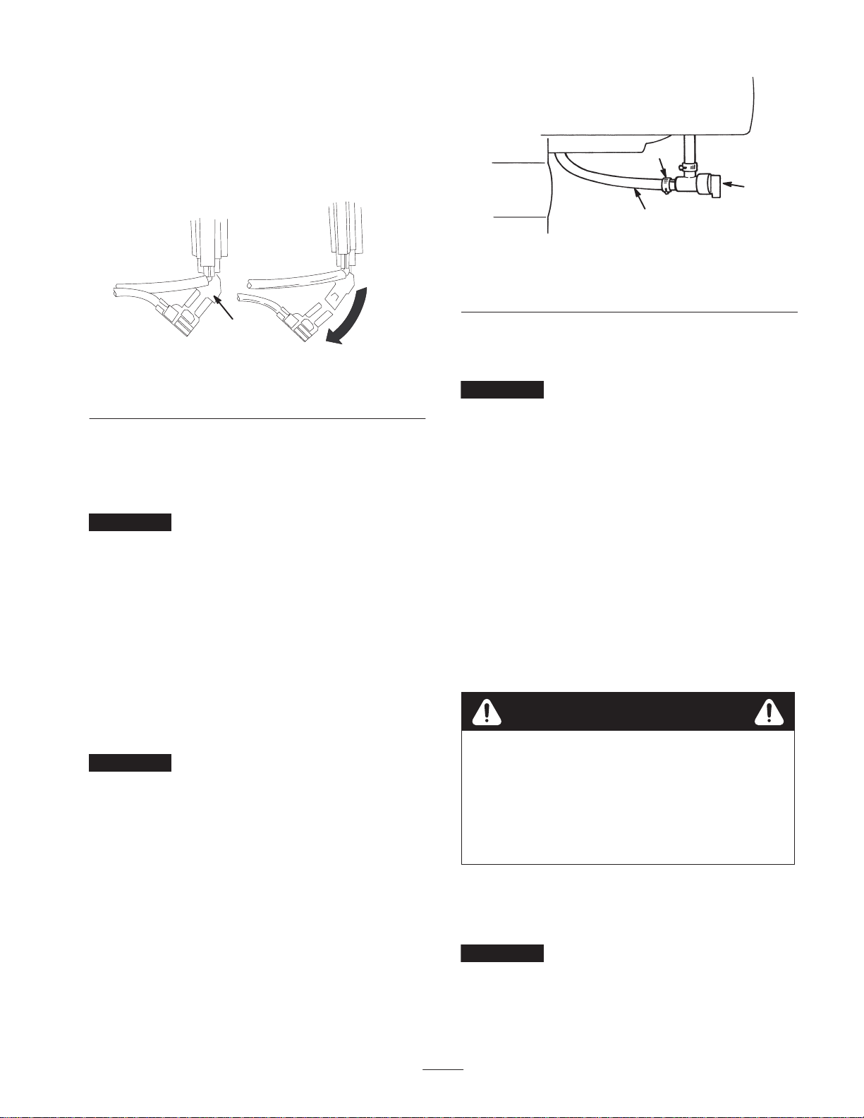
6. Disconnect the green ground wire clip under the throttle
(Fig. 17).
1. Fuel line
2. Hose clamp
2
3
726
1
Figure 18
3. Fuel shutoff valve
1
m4947
Figure 17
1. Green ground wire clip
7. Install the choke knob.
8. Insert the ignition key.
9. Connect the wire to the spark plug.
Important Use the carburetor heater box as a reference
for the choke and throttle positions.
Installing the Carburetor
Heater Box
To install the carburetor heater box, reverse steps 1 through
9 of Removing the Carburetor Heater Box on page 14.
Remove the fasteners from their holes before installing the
carburetor heater box.
Starting the Engine
Important Ensure that there are no obstructions in the
auger/impeller and the discharge chute before you operate
the snowthrower. Use a stick, not your hand, to remove an
obstruction from the auger/impeller or the discharge chute.
1. Connect the wire to the spark plug.
2. Move the throttle to the Fast position (Fig. 14).
3. Release the auger/impeller drive control lever and the
traction control lever (Fig. 13).
4. Open the fuel shutoff valve below the fuel tank
(Fig. 18).
5. Rotate the choke (Fig. 14) to the On position.
6. Insert the ignition key (Fig. 14).
Important Do not use the primer or the choke if the
engine has been running and is hot. Excessive priming may
flood the engine and prevent it from starting.
7. Cover the hole in the center of the primer (Fig. 14) with
your thumb and slowly push in the primer three times,
pausing a moment between pushes.
8. For the recoil starter:
A. Grasp the recoil starter handle (Fig. 14) and pull it
out slowly until positive engagement results; then
pull the handle vigorously to start the engine.
B. Keep a firm grip on the starter handle and return the
rope slowly.
For the electric starter:
A. Connect the power cord to the snowthrower
(Fig. 15) and to a standard household power outlet.
Caution
If you leave the snowthrower plugged into a power
outlet, someone can inadvertently start the
snowthrower and injure people or damage
property.
Unplug the power cord whenever you do are not
starting the snowthrower.
B. Push the starter button.
Note: Run the electric starter no more than ten times at
intervals of five seconds on, then five seconds off.
Important Running the electric starter extensively can
overheat and damage the starter.
15
Note: If the engine does not start after this series of
attempts, wait at least 40 minutes to allow the starter to
cool before attempting to start it again.
Page 16

Note: If the engine does not start after the second series
of attempts, take the snowthrower to an Authorized
Service Dealer for service.
C. When the engine starts, disconnect the power cord
from the snowthrower and the outlet.
Note: If engine does not start or if the air temperature is
–10F (–23C) or below, the engine may need additional
priming. After pushing in the primer, try to start the engine
before priming again.
freewheels. When you insert the axle pins through the holes
in the wheel hubs and the inner axle holes (Fig. 4) and
engage the traction control lever, the snowthrower propels
itself.
Snowthrowing Tips
Danger
9. After the engine starts, immediately rotate the choke
(Fig. 14) to the 3/4 position. As the engine warms up,
rotate the choke to the 1/2 position. When the engine
warms up sufficiently, rotate the choke to the Off
position.
10.Move the speed selector (Fig. 13) to first gear, squeeze
the traction control lever to the handgrip, and then
release the traction control lever. If the snowthrower
moves forward before engaging the traction drive
control lever or after releasing the lever, see Adjusting
the Traction Drive on page 20.
Important Do not operate the snowthrower if the auger
and impeller rotate when you disengage the auger/impeller
drive control lever.
Stopping the Engine
1. Engage the auger to clear any remaining snow from
inside the housing.
2. Run the engine for a few minutes to dry off any
accumulated moisture.
3. Release the auger/impeller drive control lever and the
traction control lever (Fig. 13).
4. Stop the engine by doing one of the following:
A. Move the throttle to the Slow position, and remove
the ignition key.
B. Move the throttle to the Stop position.
5. Close the fuel shutoff valve (Fig. 18).
6. Pull the recoil starter with a rapid, continuous, full-arm
stroke three or four times. This helps prevent the recoil
starter from freezing up.
7. Wait for all moving parts to stop before leaving the
operating position.
Freewheeling or Self-propel
Drive
You can operate the snowthrower with the self-propelling
feature engaged or disengaged (freewheeling). When you
insert the axle pins through the outer axle holes and not
through the wheel hubs (Fig. 4), the snowthrower
When the snowthrower is in operation, the
impeller and auger can be rotating and cut off or
injure hands and feet.
• Before adjusting, cleaning, repairing and
inspecting the snowthrower, and before
unclogging the discharge chute, stop the engine
and wait for all moving parts to stop. Disconnect
the wire from the spark plug and keep it away
from the plug to prevent someone from
accidentally starting the engine.
• Use a stick, not your hands, to remove an
obstruction from the discharge chute.
• Stay behind the handles and away from the
discharge opening while operating the
snowthrower.
• Keep face, hands, feet, and any other part of
your body or clothing away from concealed,
moving, or rotating parts.
Warning
The auger/impeller may pick up and throw stones,
toys, and other foreign objects, causing serious
personal injury to the operator or to bystanders.
• Keep the area to be cleared free of all objects
that could be picked up and thrown by the
auger/impeller.
• Keep all children and pets away from area of
operation.
• Adjust the skids to match the type of surface being
cleaned. Refer to Adjusting the Skids and the Scraper
on page 19.
• In snowy and cold conditions, some controls and
moving parts may freeze. Do not use excessive force
when trying to operate frozen controls. If you have
difficulty operating any control or part, start the engine
and let it run for a few minutes.
• Remove snow as soon as possible after it falls. This
produces the best snow removal results.
• Always use the Fast throttle position when throwing
snow.
• Overlap each swath to ensure complete snow removal.
16
Page 17

• Discharge the snow downwind whenever possible.
• Do not overload the snowthrower by clearing snow at
too fast a rate. If the engine slows down, shift the
snowthrower into a lower gear to reduce the forward
speed.
• In wet or slushy conditions, maintain maximum engine
speed, and do not overload the engine to prevent
clogging the discharge chute.
• If the front of the snowthrower tends to ride up, reduce
the forward speed by shifting the snowthrower into a
lower gear. If the front still tends to ride up, lift up on
both handgrips to hold down the front of snowthrower.
• If the wheels slip, shift the snowthrower into a lower
gear to reduce the forward speed.
• After clearing the snow, let the engine run for a few
minutes to prevent moving parts from freezing. Engage
the auger/impeller to clear any remaining snow from
inside the housing. Shut off the engine, wait for all
moving parts to stop, and remove all ice and snow from
the snowthrower.
• With the engine shut off, pull the recoil starter handle
several times to prevent the recoil starter from freezing
up.
• When you are not using the snowthrower, close the fuel
shutoff valve and remove the key.
Maintenance
Note: Determine the left and right sides of the machine from the normal operating position.
Recommended Maintenance Schedule
Maintenance Service
Interval
Initially
1 Hour
2 Hours • Change the engine oil. Refer to Changing the Engine Oil on page 22.
5 Hours
10 Hours
15 Hours
25 Hours • Change the engine oil. Refer to Changing the Engine Oil on page 22.
Maintenance Procedure
• Check the engine oil level.1 Refer to Checking the Engine Oil Level on page 18.
• Check the auger gearbox grease and add grease if necessary. Refer to
Checking the Auger Gearbox Grease on page 18.
2
• Adjust the skids and the scraper.
on page 19.
• Adjust the speed selector.
• Inspect and adjust the traction drive belt. Refer to Adjusting the Traction Drive
Belt on page 20.
• Inspect and adjust the auger/impeller drive belt. Refer to Adjusting the
Auger/Impeller Drive Belt on page 22.
• Inspect and adjust or replace the traction drive belt if necessary. Refer to
Adjusting the Traction Drive Belt on page 20, or to Replacing the Traction Drive
Belt on page 21.
• Inspect and adjust or replace the auger/impeller drive belt if necessary. Refer to
Adjusting the Auger/Impeller Drive Belt on page 22, or to Replacing the
Auger/Impeller Drive Belt on page 22.
• Check the auger gearbox grease and add grease if necessary. Refer to
Checking the Auger Gearbox Grease on page 18.
• Oil and grease the internal moving parts. Refer to Lubricating the Snowthrower
on page 23.
3
Refer to Adjusting the Skids and the Scraper
Refer to Adjusting the Speed Selector on page 20.
17
Page 18
Maintenance Service
Interval
Maintenance Procedure
100 Hours
Annually
1
Check the engine oil level
2
Adjust the skids and the scraper as needed.
3
Adjust the speed selector as needed.
Important Refer to your engine operator’s manual for additional maintenance procedures.
before each use
• Inspect and gap the spark plug. Replace it if necessary. Refer to Replacing the
Spark Plug on page 23.
• Check the auger gearbox grease after removing the snowthrower from storage
and add grease if necessary. Refer to Checking the Auger Gearbox Grease on
page 18.
• Change the engine oil at the end of the snowthrowing season. Refer to Changing
the Engine Oil on page 22.
• Oil and grease the internal moving parts at the end of the snowthrowing season.
Refer to Lubricating the Snowthrower on page 23.
• Drain the gasoline and run the engine to dry out the fuel tank and the carburetor
at the end of the snowthrowing season. Refer to Emptying the Fuel Tank on
page 24.
and add oil if necessary.
Caution
If you leave the wire on the spark plug, someone could accidently start the engine and seriously
injure you or other bystanders.
Disconnect the wire from the spark plug before you do any maintenance. Set the wire aside so
that it does not accidentally contact the spark plug.
Checking the Engine Oil Level
Every time you use the snowthrower, first ensure that the
oil level is between the Add and the Full marks on the
dipstick.
1. Stop the engine and wait for all moving parts to stop.
2. Move the snowthrower to a level surface to ensure an
accurate oil level reading.
3. Clean around the dipstick (Fig. 12).
4. Remove the dipstick by rotating the cap
counterclockwise and pulling it out (Fig. 12).
5. Wipe the dipstick clean with a clean cloth.
6. Install the dipstick into the filler neck, then remove it.
Note: To ensure an accurate oil level reading, you must
fully install the dipstick.
7. Read the oil level on the dipstick.
8. If the oil level is below the Add mark on the dipstick,
slowly pour only enough oil into the filler hole to raise
the oil level to the Full mark on the dipstick.
Note: Use only a high-quality, SAE 5W–30 or SAE 10
weight detergent oil that has the American Petroleum
Institute (API) service classification SF, SG, SH, or SJ.
For extremely cold conditions (below 0°F or –18°C),
use 0W–30 weight detergent oil that has the American
Petroleum Institute (API) service classification SF, SG,
SH, or SJ.
Important Do not overfill the crankcase with oil and
run the engine; engine damage will result. Drain the excess
oil until the oil level on the dipstick reads Full.
9. Insert the dipstick into the filler neck and rotate the cap
clockwise until it is tight.
Checking the Auger Gearbox
Grease
Check the auger gearbox initially, after every ten operating
hours, and when you remove the snowthrower from annual
storage.
1. Stop the engine and wait for all moving parts to stop.
2. Move the snowthrower to a level surface.
3. Disconnect the wire from the spark plug and ensure that
the wire does not contact the spark plug (Fig. 16).
18
Page 19
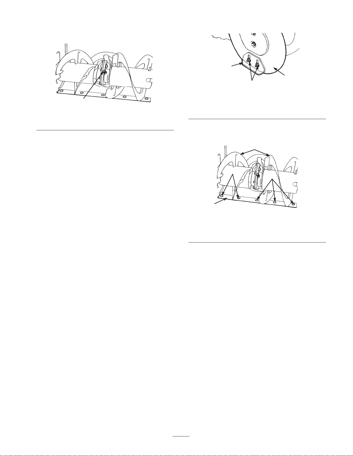
4. Clean the area around the pipe plug (Fig. 19).
1
3
2
651
6521
Figure 19
1. Pipe plug
5. Remove the pipe plug from the gearbox (Fig. 19).
6. Check the level of grease in the gearbox. The grease
should be visible through the opening.
7. If the level of grease is low, add Lubriplate MAG-1
grease (a low-temperature, high-pressure grease) to the
gearbox until the point of overflow.
8. Install the pipe plug in the gearbox.
9. Connect the wire to the spark plug.
Adjusting the Skids and the
Scraper
Adjust the skids and the scraper initially and then as needed
to ensure that the auger does not contact the paved or gravel
surface. Also, adjust them as needed to compensate for
wear.
1. Stop the engine and wait for all moving parts to stop.
2. Move the snowthrower to a level surface.
3. Disconnect the wire from the spark plug and ensure that
the wire does not contact the plug (Fig. 16).
4. Check the tire pressure in the tires. Refer to Checking
the Tire Pressure on page 13.
Figure 20
1. Skid (2)
2. Flange nuts (4)
3. Auger side plate (2)
6. Support the auger blades so that they are 1/8 inch
(3 millimeters) off the ground (Fig. 21).
3
2
2
1
652
Figure 21
1. Scraper
2. Mounting screws
3. Auger blades
7. Check the scraper adjustment. The scraper should be
1/8 inch (3 millimeters) above and parallel to a level
surface.
For Concrete and Asphalt Surfaces:
If the snowthrower does not clear the snow close enough to
the pavement, adjust the skids to lower the scraper; if the
pavement surfaces are cracked, rough, or uneven, adjust the
skids to raise the scraper.
For Gravel Surfaces:
5. Loosen the four flange nuts that secure both skids to the
auger side plates (Fig. 20) until the skids slide up and
down easily.
Support the auger blades a few inches (centimeters) above
the ground, and adjust the skids to prevent the snowthrower
from picking up rocks.
8. To adjust the scraper, loosen the five mounting screws
(Fig. 21), level the scraper, and tighten the mounting
screws.
9. Move the skids down as far as possible.
10.Tighten the four flange nuts that secure both skids to the
auger side plates (Fig. 20).
11. Connect the wire to the spark plug.
19
Page 20
Adjusting the Speed Selector
Adjust the speed selector linkage initially and when the
snowthrower is slow, first gear has no speed, or the speed
selector does not move into third gear.
1. Stop the engine and wait for all moving parts to stop.
2. Disconnect the wire from the spark plug and ensure that
the wire does not contact the spark plug (Fig. 16).
3. Tip the snowthrower forward and block it so that it
cannot fall.
4. Remove the four flange-head bolts that secure the
bottom cover to the frame and remove the cover
(Fig. 26).
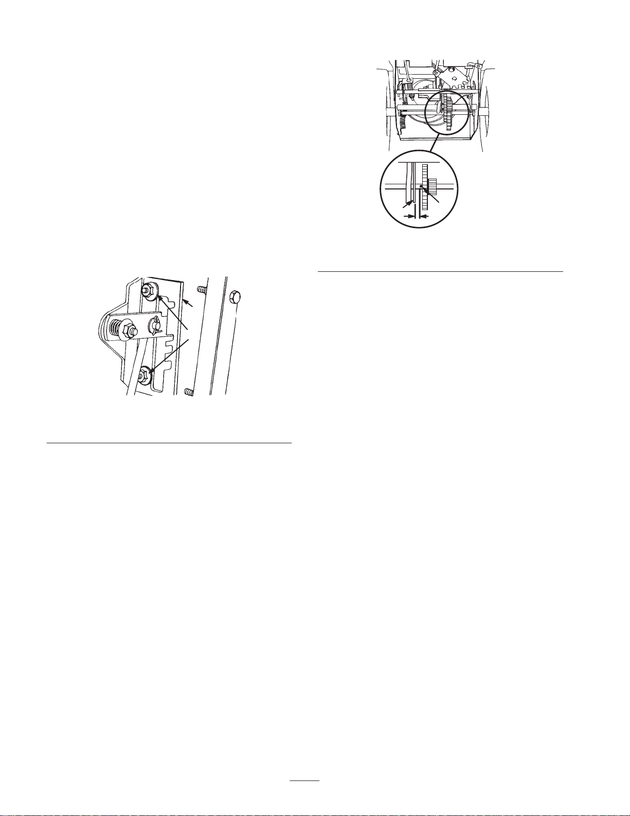
5. Loosen the flange nuts that secure the selector plate to
the control panel (Fig. 22).
1
2
659
Figure 22
1. Speed selector plate 2. Flange nuts
6. Shift the speed selector to third gear and push down on
the speed selector plate to move the drive assembly to
the right.
Note: The drive assembly should be 1/8 inch
(3 millimeters) from the roll pin; if not, slide the
selector plate (Fig. 22) until the gap is 1/8 inch
(3 millimeters); refer to Figure 23.
1
1. Roll pin 2. Drive assembly
7. With the drive assembly 1/8 inch (3 millimeters) from
the roll pin, tighten the flange nuts that secure the speed
selector plate.
8. Shift the speed selector to the R (Reverse) position and
back to third gear to check the adjustment.
9. If the space between the roll pin and the drive assembly
is more than 3/16 inch (5 millimeters), repeat steps 4
through 7.
10.Install the bottom cover and return the snowthrower to
the upright position.
11. Connect the wire to the spark plug.
2
650/913
Figure 23
Adjusting the Traction Drive
Belt
Adjust the traction drive belt after the first operating hour,
after every five operating hours thereafter, and when the
speed selector shifts properly but the snowthrower does not
drive in the forward or reverse speeds.
1. Stop the engine and wait for all moving parts to stop.
2. Disconnect the wire from the spark plug and ensure that
the wire does not contact the spark plug (Fig. 16).
3. Check and adjust the traction drive as described in steps
4 through 7 of Installing the Traction Rod on page 9.
4. If the problem persists after adjusting the linkage,
contact an Authorized Service Dealer.
5. Connect the wire to the spark plug.
20
Page 21
Replacing the Traction Drive
Belt
If the traction drive belt becomes worn, oil-soaked, or
otherwise damaged, replace the belt.
1. Stop the engine and wait for all moving parts to stop.
2. Disconnect the wire from the spark plug and ensure that
the wire does not contact the spark plug (Fig. 16).
3. Drain the gasoline from the fuel tank. Refer to
Emptying the Fuel Tank on page 24.
1
m–2592
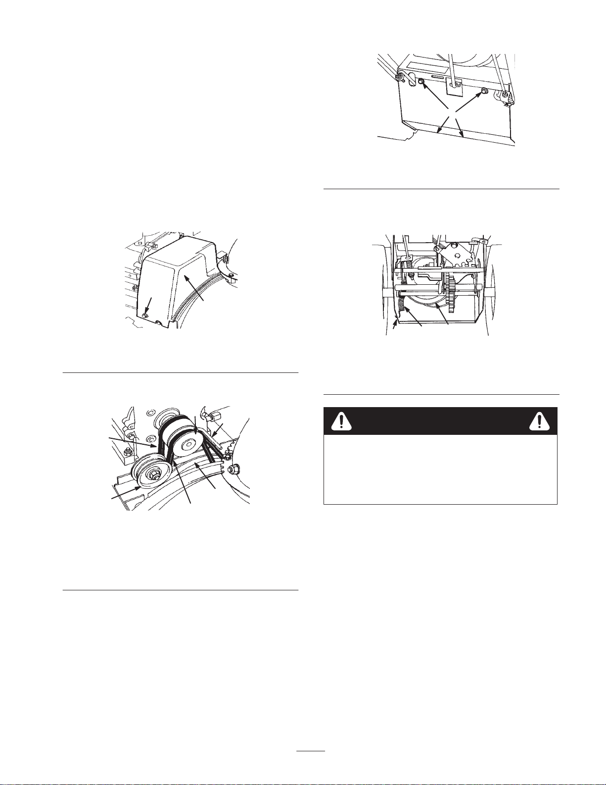
Figure 26
1. Flange-head bolts
4. Remove the two flange-head bolts that hold the belt
cover in place and set the cover aside (Fig. 24).
1
2
661
Figure 24
1. Flange-head bolt (2) 2. Belt cover
5. Loosen the belt guide (Fig. 25).
6
5
1
4
2
3
664
Figure 25
1. Traction drive belt
2. Idler pulley
3. Auger/impeller drive belt
4. Large auger/impeller
pulley
5. Belt guide
6. Engine pulley
6. Remove the auger/impeller drive belt from the engine
pulley and the large auger/impeller pulley (Fig. 25).
7. Tip the snowthrower forward and block it so that it
cannot fall.
8. Remove the four flange-head bolts that secure the
bottom cover to the frame and remove the cover
(Fig. 26).
9. Disconnect the spring from the notch in the bottom
edge of the side plate (Fig. 27).
3
1
2
650
Figure 27
1. Notch in side plate
2. Spring
3. Large traction pulley
Caution
The spring is under heavy tension and could injure
the you or a bystander if you do not carefully
remove it.
Carefully remove the spring.
10.Set the snowthrower upright.
11. Remove the traction drive belt from the engine pulley
and the large traction pulley (Fig. 25).
12.Install a new belt around the large traction pulley.
13.Loop the belt over the engine pulley, ensuring that the
belt is on the inside of the belt guide (Fig. 25).
14.Tip the snowthrower forward and block it so that it
cannot fall.
15.Hook the spring into the notch in the bottom edge of the
side plate (Fig. 27).
16.Replace the bottom cover with the four flange-head
bolts.
21
Page 22

17.Set the snowthrower upright.
18.Install the auger/impeller drive belt around the large
auger/impeller pulley and engine pulley, ensuring that
the belt is on the inside of the idler pulley and the belt
guide (Fig. 25).
19.Adjust the belt guide so that there is 1/8 inch
(3 millimeters) of clearance between the auger/impeller
drive belt and the guide, and secure the belt guide when
the auger/impeller drive belt is tight.
6. If the belt still slips, replace it. Refer to Replacing the
Auger/Impeller Drive Belt on page 22.
Important Do not operate the snowthrower if the auger
and the impeller rotate when you disengage the
auger/impeller drive control lever.
Replacing the Auger/Impeller
Drive Belt
20.Check the auger/impeller drive linkage and adjust it if
necessary. Refer to steps 4 through 7 of Installing the
Auger/Impeller Drive Control Linkage on page 10.
21.Install the belt cover.
22.Connect the wire to the spark plug.
Adjusting the Auger/Impeller
Drive Belt
Operating the snowthrower with an auger/impeller drive
belt that slips decreases the snowthrowing performance and
damages the belt. Check the auger/impeller drive belt for
the proper tension after the first operating hour, after every
five operating hours thereafter. Adjust the belt when
necessary.
Danger
Improperly adjusting the auger/impeller may
cause it to turn when disengaged. A rotating auger
or impeller can cut off or injure fingers, hands, or
feet.
• Keep your face, hands, feet, and any other part
of your body or clothing away from concealed,
moving, or rotating parts.
• Ensure that the impeller brake arm clearance is
maintained.
• Do not adjust the auger/impeller drive belt too
tight because it may cause the auger/impeller to
turn when the control lever is in the Disengaged
position. If this occurs, decrease the belt tension.
If the auger/impeller drive belt becomes worn, oil-soaked,
or otherwise damaged, replace the belt.
1. Stop the engine and wait for all moving parts to stop.
2. Disconnect the wire from the spark plug and ensure that
the wire does not contact the plug (Fig. 16).
3. Remove the two flange-head bolts that hold the belt
cover in place and set the cover aside (Fig. 24).
4. Loosen the belt guide (Fig. 25).
5. Remove the auger/impeller drive belt from the engine
pulley and the large auger/impeller pulley (Fig. 25).
6. Install a new belt around the large auger/impeller pulley
(Fig. 25).
7. Loop the belt over the engine pulley, ensuring that the
belt is on the inside of the idler pulley and the belt guide
(Fig. 25).
8. Adjust the belt guide so that there is 1/8 inch
(3 millimeters) of clearance between the auger/impeller
drive belt and the guide, and secure the belt guide.
9. Check and adjust the auger/impeller drive belt as
instructed in steps 4 through 7 of Installing the
Auger/Impeller Drive Control Linkage on page 10.
10.Install the belt cover.
11. Connect the wire to the spark plug.
Important Do not operate the snowthrower if the auger
and the impeller rotate when you disengage the
auger/impeller drive control lever.
1. Stop the engine and wait for all moving parts to stop.
2. Disconnect the wire from the spark plug and ensure that
the wire does not contact the plug (Fig. 16).
3. Check and adjust the belt as instructed in steps 4
through 7 of Installing the Auger/Impeller Drive
Control Linkage on page 10.
4. Connect the wire to the spark plug.
5. Check the belt tension by operating the auger.
Changing the Engine Oil
Change the engine oil after the first two operating hours,
after every 25 operating hours, and at the end of the
snowthrowing season. If possible, run the engine just
before changing the oil because warm oil flows better and
carries more contaminants.
1. Stop the engine and wait for all moving parts to stop.
2. Disconnect the wire from the spark plug and ensure that
the wire does not contact the spark plug (Fig. 16).
3. Block up the rear of the snowthrower.
22
Page 23

4. Remove the left wheel.
5. Clean the area around the oil drain plug (Fig. 28).
1
2
Figure 28
1. Oil drain plug 2. Drain extension
6. Slide an oil drain pan below the drain extension and
remove the oil drain plug (Fig. 28).
Note: Place a funnel under the drain extension so the oil
drains directly into the oil drain pan and away from the
snowthrower.
7. Drain the oil.
8. Install the oil drain plug.
9. Install the left wheel.
10.Fill the crankcase with oil. Refer to Filling the Engine
Crankcase with Oil on page 12.
11. Wipe up any spilled oil.
12.Connect the wire to the spark plug.
m–4070
Lubricating the Snowthrower
Lightly lubricate all moving parts of the snowthrower after
every 15 operating hours and at the end of the
snowthrowing season.
Important Do not get oil or grease on the rubber wheel
or friction drive plate because the wheel will slip and the
rubber may deteriorate.
887
Figure 29
Important Do not excessively oil the snowthrower;
extra oil may enter the traction drive and cause the traction
drive belt to slip.
7. Wipe up any excess oil.
8. Grease the snowthrower as shown in Figure 29.
9. Wipe up any excess grease.
10.Install the bottom cover.
11. Return the snowthrower to its upright position.
12.Connect the wire to the spark plug.
Replacing the Spark Plug
Use a Champion RJ-19LM or equivalent spark plug. Install
a new plug after every 100 operating hours.
1. Stop the engine and wait for all moving parts to stop.
2. Clean any debris from around the base of the spark
plug.
3. Disconnect the wire from the spark plug (Fig. 16).
4. Remove the spark plug.
5. Examine the spark plug and replace it if it is cracked,
fouled, dirty, or if the electrodes are worn.
1. Stop the engine and wait for all moving parts to stop.
2. Disconnect the wire from the spark plug and ensure that
the wire does not contact the plug (Fig. 16).
3. Drain gasoline from the fuel tank. Refer to Emptying
the Fuel Tank on page 24.
4. Tip the snowthrower forward onto the auger/impeller
housing and block it so that it cannot fall.
5. Remove the four flange-head bolts that secure the
bottom cover and remove the cover (Fig. 26).
6. Lightly lubricate the snowthrower with light oil as
shown in Figure 29.
Important Do not clean the electrodes because grit
could enter the cylinder and damage the engine.
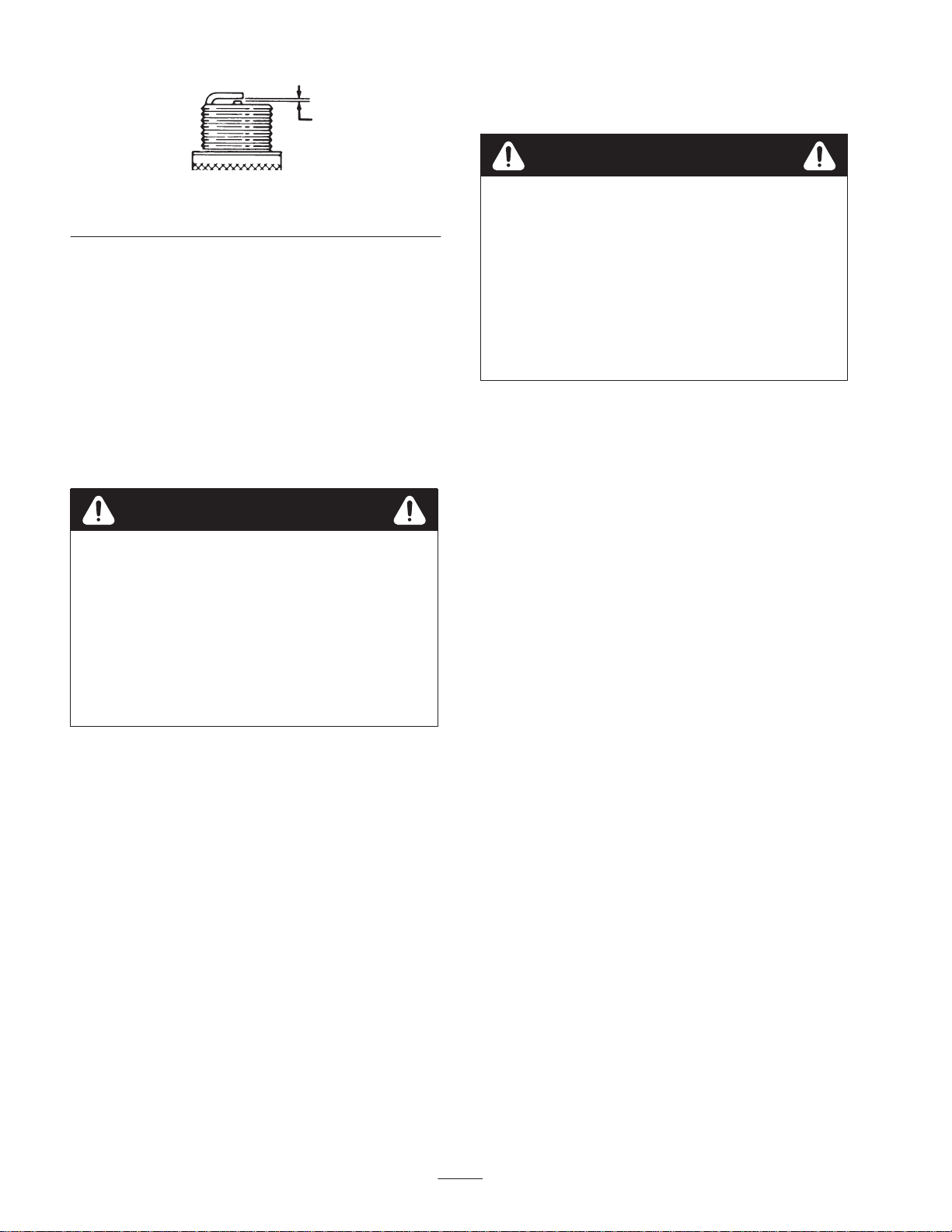
6. Set the gap between the electrodes on the spark plug at
0.030 in. (0.76 mm) as shown in Figure 30.
23
Page 24
1
Storage
110
Figure 30
1. 0.030 in. (0.76 mm)
7. Install the spark plug by hand and then torque it to
15 ft-lb (20.4 Nm). If you do not have a torque wrench,
tighten the plug firmly.
8. Connect the wire to the spark plug.
Emptying the Fuel Tank
1. Stop the engine and wait for all moving parts to stop.
2. Disconnect the wire from the spark plug (Fig. 16)
3. Close the fuel shutoff valve (Fig. 18).
Danger
Gasoline is highly flammable; it can ignite and
cause serious personal injury.
• Drain gasoline outdoors.
• Drain gasoline from a cold engine only.
• Wipe up any gasoline that may have spilled.
• Do not drain gasoline near any open flame or
where gasoline fumes may be ignited by a spark.
• Do not smoke a cigar, a cigarette, or a pipe when
handling gasoline.
4. Place a clean drain pan under the fuel shutoff valve.
Warning
Gasoline fumes are highly flammable, explosive,
and dangerous if inhaled. If the product is stored
in an area with an open flame, the gasoline fumes
may ignite and cause an explosion.
Do not store the snowthrower in a house (living
area), basement, or any other area where ignition
sources may be present, such as hot water and
space heaters, clothes dryers, furnaces, and other
like appliances.
Preparing the Fuel System
1. Add stabilizer/conditioner to the fuel in the fuel tank as
directed.
2. Run the engine for ten minutes to distribute conditioned
fuel through the fuel system.
3. Stop the engine, allow it to cool, and drain the fuel tank
or run the engine until it stops. Refer to Emptying the
Fuel T ank on page 24.
4. Start the engine and run it until it stops.
5. Choke or prime the engine, start it a third time, and run
the engine until it will not start.
6. Dispose of unused fuel properly. Recycle it according to
local codes, or use it in your automobile.
Note: Do not store stabilized gasoline for more than 90
days.
5. Loosen the hose clamp that secures the fuel line to the
valve and slide the fuel line off the fuel shutoff valve
(Fig. 18).
6. Open the fuel shutoff valve and allow the fuel to drain
out of the fuel tank into the drain pan.
7. Install the fuel line onto the fuel shutoff valve and
secure it with a hose clamp.
8. Connect the wire to the spark plug.
9. Start the snowthrower and run the engine until it stops.
Repeat this step two more times to ensure that the fuel
tank and the carburetor are empty.
Preparing the Engine
1. While the engine is still warm, change the engine oil.
Refer to Changing the Engine Oil on page 22.
2. Remove the spark plug.
3. Use an oil can to squirt two teaspoons of oil into the
spark plug hole.
4. Install the spark plug by hand and then torque it to
15 ft-lb (20.4 Nm). If you do not have a torque wrench,
tighten the plug firmly. Do not connect the wire to the
plug.
5. Pull the recoil starter slowly to distribute the oil on the
inside of the cylinder.
Preparing the Snowthrower
1. Lubricate the snowthrower. Refer to Lubricating the
Snowthrower on page 23.
24
Page 25

2. Clean the snowthrower.
Engine does not start or starts
1.The key is not in the ignition or
1.Insert the key into the ignition
3. Touch up chipped surfaces with paint available from an
Authorized Service Dealer. Sand affected areas before
painting, and use a rust preventative to prevent the
metal parts from rusting.
4. Tighten any loose fasteners. Repair or replace any
damaged parts.
Accessories
You can obtain the following snowthrower accessories
from your Authorized Service Dealer:
• Tire Chain Kit
• Drift Breaker Kit
5. Cover the snowthrower and store it in a clean, dry place
out of the reach of children. Allow the engine to cool
before storing it in any enclosure.
• Snow Shield Kit
Troubleshooting
Toro designed and built your snowthrower for trouble-free operation. Check the following components and items carefully,
and refer to Maintenance on page 17 for more information. If a problem continues, see an Authorized Service Dealer.
Problem Possible Causes Corrective Action
Electric starter does not turn
(electric-start models only)
Engine does not start or starts 1. The key is not in the ignition or 1. Insert the key into the ignition
hard
1. The power cord is
disconnected at the outlet or
the snowthrower.
2. The power cord is worn,
corroded, or damaged.
3. The power outlet is not
energized.
is in the
2. The choke is in the
and the primer has not been
pressed.
Off
position.
Off
position
1. Connect the power cord to the
outlet and/or the snowthrower.
2. Replace the power cord.
3. Have a qualified electrician
energize the power outlet.
and turn it to the On position.
2. Move the choke to the
position and press the primer
three times.
On
3. The fuel shutoff valve is not
open.
4. The throttle is not in the
position.
5. The fuel tank is empty or the
fuel system contains stale fuel.
6. The spark plug wire is loose or
disconnected.
7. The spark plug is pitted, fouled,
or the gap is incorrect.
8. The fuel cap vent is restricted. 8. Remove the vent restriction or
9. The engine oil level in the
engine crankcase is too low or
too high.
Fast
3. Open the fuel shutoff valve.
4. Move the throttle to the
position.
5. Drain and/or fill the fuel tank
with fresh gasoline (not more
than 30 days old). If the
problem persists, contact your
Authorized Service Dealer.
6. Connect the wire to the spark
plug.
7. Check the spark plug and
adjust the gap if necessary.
Replace the spark plug if it is
pitted, fouled, or cracked.
replace the fuel cap.
9. Add or drain oil to adjust the oil
level in engine crankcase to the
Full
mark on the dipstick.
Fast
25
Page 26

Problem Corrective ActionPossible Causes
10.The air temperature is above
40°F (4°C) and the carburetor
heater box is on the
snowthrower.
Engine runs rough 1. The choke is in the On position. 1. Move the choke to the
2. The fuel shutoff valve is not
completely open.
3. The fuel tank is nearly empty or
contains stale fuel.
4. The spark plug wire is loose. 4. Connect the wire to the spark
5. The spark plug is pitted, fouled,
or the gap is incorrect.
6. The engine oil level in the
engine crankcase is too low or
too high.
10.Remove the carburetor heater
box.
position.
2. Open the fuel shutoff valve.
3. Drain and fill the fuel tank with
fresh gasoline (not more than
30 days old). If the problem
persists, contact an Authorized
Service Dealer.
plug.
5. Check the spark plug and
adjust the gap if necessary.
Replace the spark plug if it is
pitted, fouled, or cracked.
6. Add or drain the oil level in the
engine crankcase to the
mark on the dipstick.
Off
Full
Engine runs, but the snowthrower
discharges snow poorly or not at
all
7. The air temperature is above
40°F (4°C) and the carburetor
heater box is on the
snowthrower.
1. The throttle is not in the
position when throwing snow.
2. The snowthrower is moving too
fast to clear the snow.
3. You are trying to remove too
much snow per swath.
4. You are trying to remove
extremely heavy or wet snow.
5. The discharge chute is
plugged.
6. The auger/impeller drive belt is
loose or is off the pulley.
7. The auger/impeller drive belt is
worn or broken.
Fast
7. Remove the carburetor heater
box.
1. Move the throttle to the
position.
2. Shift the snowthrower into a
lower gear.
3. Reduce the amount of snow
removed for per swath.
4. Don’t overload the snowthrower
with extremely heavy or wet
snow.
5. Stop the engine, wait for all
moving parts to stop, and use a
stick to remove the snow from
the discharge chute.
6. Install and/or adjust the
auger/impeller drive belt.
7. Replace the auger/impeller
drive belt.
Fast
Snowthrower does not properly
clear the snow off the surface
1. The tire pressure is low. 1. Check the pressure in the tires
and adjust it if necessary.
2. The skids and/or the scraper is
not properly adjusted.
2. Adjust the skids and the
scraper.
26
Page 27

27
Page 28

Gas Powered
Snow Products
The Toro Total Coverage Guarantee
A Two-Year Full Warranty
(Limited Warranty for Commercial Use)
Conditions and Products Covered
The Toro Company and its affiliate, Toro Warranty Company,
pursuant to an agreement between them, jointly promise to repair
any Toro Product used for normal residential purposes* if defective
in materials or workmanship for a period of two years from the date
of purchase.
This warranty includes the cost of parts and labor, but you must
pay transportation costs. Transportation within a fifteen mile radius
of the servicing dealer is covered under this warranty for two-stage
snowthrowers only.
This warranty applies to all gasoline powered snow products.
* Normal residential purposes means use of the product on the
same lot as your home. Use at more than one location is
considered commercial use, and the commercial use warranty
would apply.
Limited Warranty for Commercial Use
Toro Consumer Products used for commercial, institutional, or
rental use are warranted against defects in materials or workmanship for 45 days from the date of purchase.
Instructions for Obtaining Warranty Service
If you think that your Toro Product contains a defect in materials or
workmanship, follow this procedure:
1. Contact any Toro Authorized or Master Service Dealer to
arrange service at their dealership. To locate a dealer
convenient to you, refer to the Yellow Pages of your telephone
directory (look under “Lawn Mowers”) or access our website at
www.Toro.com. U.S. Customers may also call 800-421-9684
to use our 24-hour Toro dealer locator system.
2. Bring the product and your proof of purchase (sales receipt) to
the Service Dealer.
If for any reason you are dissatisfied with the Service Dealer’s
analysis or with the assistance provided, contact us at:
Customer Care Department, Consumer Division
Toro Warranty Company
8111 Lyndale Avenue South
Bloomington, MN 55420-1196
800-348-2424 (U.S. customers)
877-484-9255 (Canada customers)
Y ou must maintain your Toro Product by following the maintenance
procedures described in the operator’s manual. Such routine
maintenance, whether performed by a dealer or by you, is at your
expense.
There is no other express warranty except for special emission
system coverage on some products and the Toro Starting
Guarantee on GTS engines. This express warranty does not
cover:
• Cost of regular maintenance service or parts, such as filters,
fuel, lubricants, tune-up parts, blade sharpening, brake and
clutch adjustments
• Any product or part which has been altered or misused or
required replacement or repair due to normal wear, accidents,
or lack of proper maintenance
• Repairs necessary due to improper fuel, contaminants in the
fuel system, or failure to properly prepare the fuel system prior
to any period of non-use over three months
All repairs covered by this warranty must be performed by an
Authorized Toro Service Dealer using Toro approved replacement
parts.
Repair by an Authorized Toro Service Dealer is your sole remedy
under this warranty.
Neither The Toro Company nor Toro Warranty Company is liable
for indirect, incidental or consequential damages in connection
with the use of the Toro Products covered by this warranty,
including any cost or expense of providing substitute equipment or
service during reasonable periods of malfunction or non-use
pending completion of repairs under this warranty.
Some states d o n o t a l l o w exclusions of incidental or consequential
damages, or limitations on how long an implied warranty lasts, so
the above exclusions and limitations may not apply to you.
This warranty gives you specific legal rights, and you may also
have other rights which vary from state to state.
Owner Responsibilities
Items and Conditions Not Covered
General Conditions
Countries Other than the United States or Canada
Customers who have purchased Toro products exported from the United States or Canada should contact their T oro Distributor (Dealer)
to obtain guarantee policies for your country , province, or state. If for any reason you are dissatisfied with your Distributor’s service or
have difficulty obtaining guarantee information, contact the Toro importer. I f all other remedies fail, you may contact us at Toro Warranty
Company.
Part No. 374-0011 Rev. A
 Loading...