

Page 1

FormNo.3420-243RevB
CommercialWalk-Behind
TractionUnit
18HPPistol-GripHydroDrive
ModelNo.31914—SerialNo.400000000andUp
Registeratwww.T oro.com.
OriginalInstructions(EN)
*3420-243*B
Page 2
ThisproductcomplieswithallrelevantEuropean
directives;fordetails,pleaseseetheseparateproduct
specicDeclarationofConformity(DOC)sheet.
Introduction
Thisrotary-blade,lawnmowerisintendedtobe
usedbyprofessional,hiredoperators.Itisdesigned
primarilyforcuttinggrassonwell-maintainedlawnson
residentialorcommercialproperties.Itisnotdesigned
forcuttingbrushorforagriculturaluses.
Readthisinformationcarefullytolearnhowtooperate
andmaintainyourproductproperlyandtoavoid
injuryandproductdamage.Thismanualshouldbe
consideredaspartofthemachine,asitcontains,
safety,operationalandmaintenanceinformation.The
mowerisaprecisionbuiltmachinedesignedsolelyfor
cuttinggrassandsimilarlowlyinggroundvegetation
withinthelimitationsstatedinthismanual.Youare
responsibleforoperatingtheproductproperlyand
safely.
g250801
Figure1
1.Modelandserialnumberlocation
ModelNo.
SerialNo.
YoumaycontactT orodirectlyforproductsafetyand
operationtrainingmaterials,accessoryinformation,
helpndingadealer,ortoregisteryourproduct
atToroCommercialProductsServiceDepartment
Spellbrook,BishopsStortford,CM234BU,England,
+44(0)1279603019,Email:uk.service@toro.com.
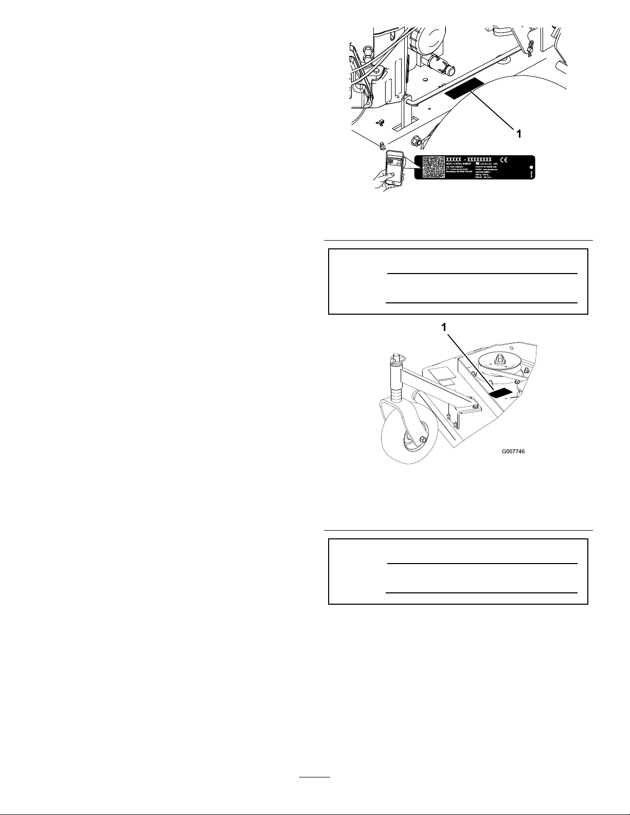
Wheneveryouneedservice,genuineToroparts,or
additionalinformation,contactanAuthorizedService
DealerorToroCustomerServiceandhavethemodel
andserialnumbersofyourproductready.Figure1
andFigure2identifythelocationofthemodeland
serialnumbersontheproduct.Writethenumbersin
thespaceprovided.
Important:Withyourmobiledevice,youcan
scantheQRcodeontheserialnumberdecal(if
equipped)toaccesswarranty,parts,andother
productinformation.
g007746
Figure2
Rear-dischargedeckshown
1.Modelandserialnumberlocation
ModelNo.
SerialNo.
Thismanualidentiespotentialhazardsandhas
safetymessagesidentiedbythesafety-alertsymbol
(Figure3),whichsignalsahazardthatmaycause
seriousinjuryordeathifyoudonotfollowthe
recommendedprecautions.
©2018—TheToro®Company
8111LyndaleAvenueSouth
Bloomington,MN55420
Contactusatwww.Toro.com.
2
PrintedintheUSA.
AllRightsReserved
Page 3

Figure3
1.Safety-alertsymbol
Thismanualuses2wordstohighlightinformation.
Importantcallsattentiontospecialmechanical
informationandNoteemphasizesgeneralinformation
worthyofspecialattention.
Contents
Safety.......................................................................4
SafeOperatingPractices....................................4
SafetyandInstructionalDecals..........................5
Setup........................................................................8
1CheckingtheFluidsandTirePressure.............8
2InstallingtheWheelKit.....................................8
3ReadingtheManualandViewingthe
OperatorTrainingMaterial..............................8
ProductOverview.....................................................9
Controls.............................................................9
Specications..................................................10
Attachments/Accessories.................................10
Operation.................................................................11
AddingFuel.......................................................11
ThinkSafetyFirst..............................................12
OperatingtheParkingBrake.............................12
StartingtheEngine...........................................12
ShuttingOfftheEngine.....................................13
OperatingtheNeutralLocks.............................13
OperatingtheBlade-ControlKnob
(PTO)............................................................14
UsingtheSafety-InterlockSystem....................14
DrivingtheMachineForwardand
Backward......................................................15
BringingtheMachinetoNeutral........................15
PushingtheMachinebyHand..........................15
TransportingtheMachine.................................16
AdjustingtheHeightofCut...............................16
AdjustingtheCasterPosition............................17
AdjustingtheHandleHeight.............................18
Height-of-CutChart..........................................19
Maintenance...........................................................20
RecommendedMaintenanceSchedule(s)...........20
Lubrication..........................................................21
LubricatingtheCasterandWheel
Bearings........................................................21
GreasingtheMower-BeltIdler..........................21
GreasingthePumpControlandBell
Crank............................................................21
EngineMaintenance...........................................22
ServicingtheAirCleaner..................................22
ServicingtheEngineOil....................................23
ServicingtheSparkPlug...................................25
FuelSystemMaintenance...................................26
g000502
ServicingtheFuelT ank.....................................26
ServicingtheFuelFilter....................................27
DriveSystemMaintenance..................................28
AdjustingtheSpeed-ControlLinkage................28
AdjustingtheNeutralControlLinkages.............29
AdjustingtheHydraulicControl
Linkages.......................................................30
AdjustingtheControlRod.................................31
AdjustingtheTracking.....................................32
AdjustingtheSpringAnchorLinks....................32
CheckingtheTirePressure...............................33
CoolingSystemMaintenance..............................33
CleaningtheAirIntakeScreen..........................33
BrakeMaintenance.............................................34
ServicingtheBrake..........................................34
BeltMaintenance................................................35
CheckingtheBelts............................................35
ReplacingtheMowerBelt.................................35
AdjustingtheMowerBeltT ension.....................35
HydraulicSystemMaintenance...........................38
ServicingtheHydraulicSystem........................38
MowerDeckMaintenance....................................41
ServicingtheCuttingBlades.............................41
AdjustingtheBladeBrake.................................43
Storage...................................................................43
Troubleshooting......................................................45
Schematics.............................................................47
3
Page 4

Safety
Improperuseormaintenancebytheoperatororowner
canresultininjury.T oreducethepotentialforinjury,
complywiththesesafetyinstructionsandalwayspay
attentiontothesafety-alertsymbol,whichmeans
Caution,Warning,orDanger—personalsafety
instruction.Failuretocomplywiththeinstructionmay
resultinpersonalinjuryordeath.
Thismachinehasbeendesignedinaccordancewith
ENISO5395:2013.
SafeOperatingPractices
Training
•ReadtheOperator'sManualandothertraining
material.
•Iftheoperator(s)ormechanic(s)cannotreadthe
manuallanguage,itistheowner'sresponsibilityto
explainthismaterialtothem.
•Becomefamiliarwiththesafeoperationofthe
equipment,operatorcontrols,andsafetysigns.
•Alloperatorsandmechanicsshouldbetrained.
Theownerisresponsiblefortrainingtheusers.
•Neverletchildrenoruntrainedpeopleoperateor
servicetheequipment.Localregulationsmay
restricttheageoftheoperator.
•Theowner/usercanpreventandisresponsible
foraccidentsorinjuriesoccurringtopeople,or
damagetoproperty.
Preparation
•Evaluatetheterraintodeterminewhataccessories
andattachmentsyouneedtoproperlyandsafely
performthejob.Useonlyaccessoriesand
attachmentsapprovedbythemanufacturer.
•Wearappropriateclothingincludingeyeprotection,
longplants,substantialslip-resistantfootwear,and
hearingprotection.Tiebacklonghairanddonot
wearlooseclothingorloosejewelry.
•Inspecttheareawhereyouwillusetheequipment
andremoveallobjectssuchasrocks,toys,and
wire,whichcanbecontactedbythemachine.
•Checkthattheoperator-presencecontrols,
safetyswitches,andshieldsareattachedand
functioningproperly.Donotoperateunlessthey
arefunctioningproperly.
SafeHandlingofFuels
•Useextracarewhenhandlingfuel.Theyare
ammableandvaporsareexplosive.
•Extinguishallcigarettes,cigars,pipes,andother
sourcesofignition.
•Useonlyanapprovedfuelcontainer.
•Donotremovethefuelcaporllthefueltank
whiletheengineisrunningorhot.
•Donotaddordrainfuelinanenclosedspace.
•Donotstorethemachineorfuelcontainerwhere
thereisanopename,spark,orpilotlight,such
asonawaterheaterorotherappliance.
•Ifyouspillfuel,donotattempttostarttheengine;
avoidcreatinganysourceofignitionuntilthefuel
vaporshavedissipated.
Operation
•Useyourfullattentionwhileoperatingthe
machine.Donotengageinanyactivitythat
causesdistractions;otherwise,injuryorproperty
damagemayoccur.
•Lightningcancausesevereinjuryordeath.If
lightningisseen,orthunderisheardinthearea,
donotoperatethemachine;seekshelter.
•Donotrunanengineinanenclosedarea.
•Operateonlyinwell-litareas,keepingawayfrom
holesandhiddenhazards.
•Ensurethatalldrivesareinneutralandthatthe
parkingbrakeisengagedbeforestartingengine.
Starttheengineonlyfromtheoperator’sposition.
•Makesurethatyouhavegoodfootingwhile
usingthismachine,especiallywhenbackingup.
Reducedfootingcouldcauseslipping.
•Donotraisethemowerdeckwiththeblades
running.
•DonotoperatethemachinewithoutthePTO
shieldorotherguardssecurelyinplace.Besure
thatallinterlocksareattached,adjustedproperly ,
andfunctioningproperly.
•Donotoperatewiththedischargedeectorraised,
removedoraltered,unlessyouareusingagrass
catcher.
•Donotchangetheenginegovernorsettingor
overspeedtheengine.
•Parkthemachineonalevelsurface,disengage
drives,engagetheparkingbrake,shutoffthe
engine,andremovethekeybeforeleavingthe
operator'spositionforanyreason,including
emptyingthecatchersoruncloggingthechute.
•Stopthemachine,shutofftheengine,removethe
key,andinspectthebladesafterstrikingobjects
orifanabnormalvibrationoccurs.Makethe
necessaryrepairsbeforeresumingoperation.
4
Page 5

•Keepyourhandsandfeetawayfromthecutting
unit.
•Lookbehindanddownbeforebackingupto
ensureaclearpath.
•Keeppetsandbystandersawayfromanoperating
machine.
•Slowdownandusecautionwhenmakingturns
andcrossingroadsandsidewalks.Stopthe
bladesifyouarenotmowing.
•Beawareofthemower-dischargedirectionand
donotpointitatanyone.
•Donotoperatethemachinewhileill,tired,or
undertheinuenceofalcoholordrugs.
•Usecarewhenloadingorunloadingthemachine
intoorfromatrailerortruck.
•Usecarewhenapproachingblindcorners,shrubs,
trees,orotherobjectsthatmayobscurevision.
SlopeSafety
•Mowacrossthefaceofslopes;neverupand
down.Useextremecautionwhenchanging
directiononslopes.
•Donotmowonexcessivelysteepslopes.Poor
footingcouldcauseaslip-and-fallaccident.
•Mowwithcautionneardrop-offs,ditches,or
embankments.
MaintenanceandStorage
•Parkthemachineonalevelsurface,disengage
drives,engagetheparkingbrake,shutoffthe
engine,andremovethekeyordisconnect
spark-plugwire.Waitforallmovementtostop
beforeadjusting,cleaning,orrepairing.
•Cleangrassanddebrisfromthecuttingunit,
drives,mufers,andenginetohelppreventres.
•Cleanupoilorfuelspills.
•Lettheenginecoolbeforestoringthemachine.
•Donotstorefuelnearamesordrainfuelindoors.
•Donotallowuntrainedpersonneltoservicethe
machine.
•Usejackstandstosupportcomponentswhen
required.
•Carefullyreleasepressurefromcomponentswith
storedenergy.
•Disconnectthebatteryorremovethespark-plug
wirebeforemakinganyrepairs.Disconnectthe
negativeterminalrstandthepositiveterminal
last.Connectthepositiveterminalrstand
negativelast.
•Usecarewhencheckingtheblades.Wrapthe
blade(s)orwearthicklypaddedgloves,anduse
cautionwhenservicingthem.Onlyreplaceblades;
donotstraightenorweldthem.
•Keephandsandfeetawayfrommovingparts.If
possible,donotmakeadjustmentswiththeengine
running.
•Keepallpartsingoodworkingconditionandall
hardwaretightened.Replaceallwornordamaged
decals.
SafetyandInstructionalDecals
Safetydecalsandinstructionsareeasilyvisibletotheoperatorandarelocatednearanyarea
ofpotentialdanger.Keepsafetysignsclearandvisible,replaceanydecalthatisdamaged
ormissing.
Manufacturer'sMark
1.Indicatesthebladeisidentiedasapartfromtheoriginal
machinemanufacturer.
decaloemmarkt
decal320006
320006
1.Heightofcut
5
Page 6
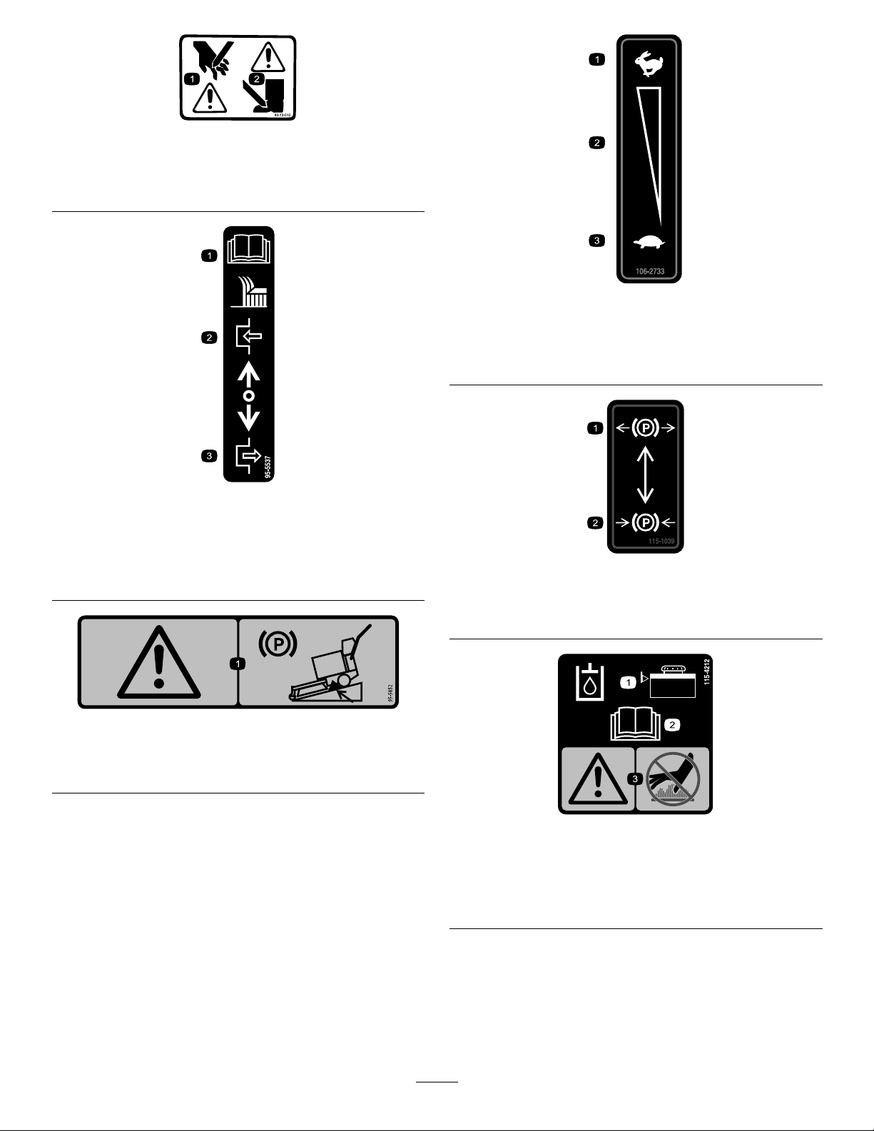
1.Cuttinghazardofhand
2.Cuttinghazardoffoot
decal40-13-010
40-13–010
decal106-2733
106-2733
1.ReadtheOperator's
Manualforinstructionson
operatingthecuttingblade
2.Pushforwardtoengage
1.Fast
3.Slow
2.Continuousvariable
setting
decal95-5537(hydro)
95-5537
3.Pullbacktodisengage
decal115-1039
115-1039
1.Parking
brake—disengaged
decal95-5852
2.Parkingbrake—engaged
95-5852
1.Warning—engagetheparkingbrakeandblockthewheels
whenparkingonaslope.
1.Hydraulic-uidlevel
2.ReadtheOperator's
6
decal115-4212
115-4212
3.Warning—donottouchthe
hotsurface.
Manual.
Page 7
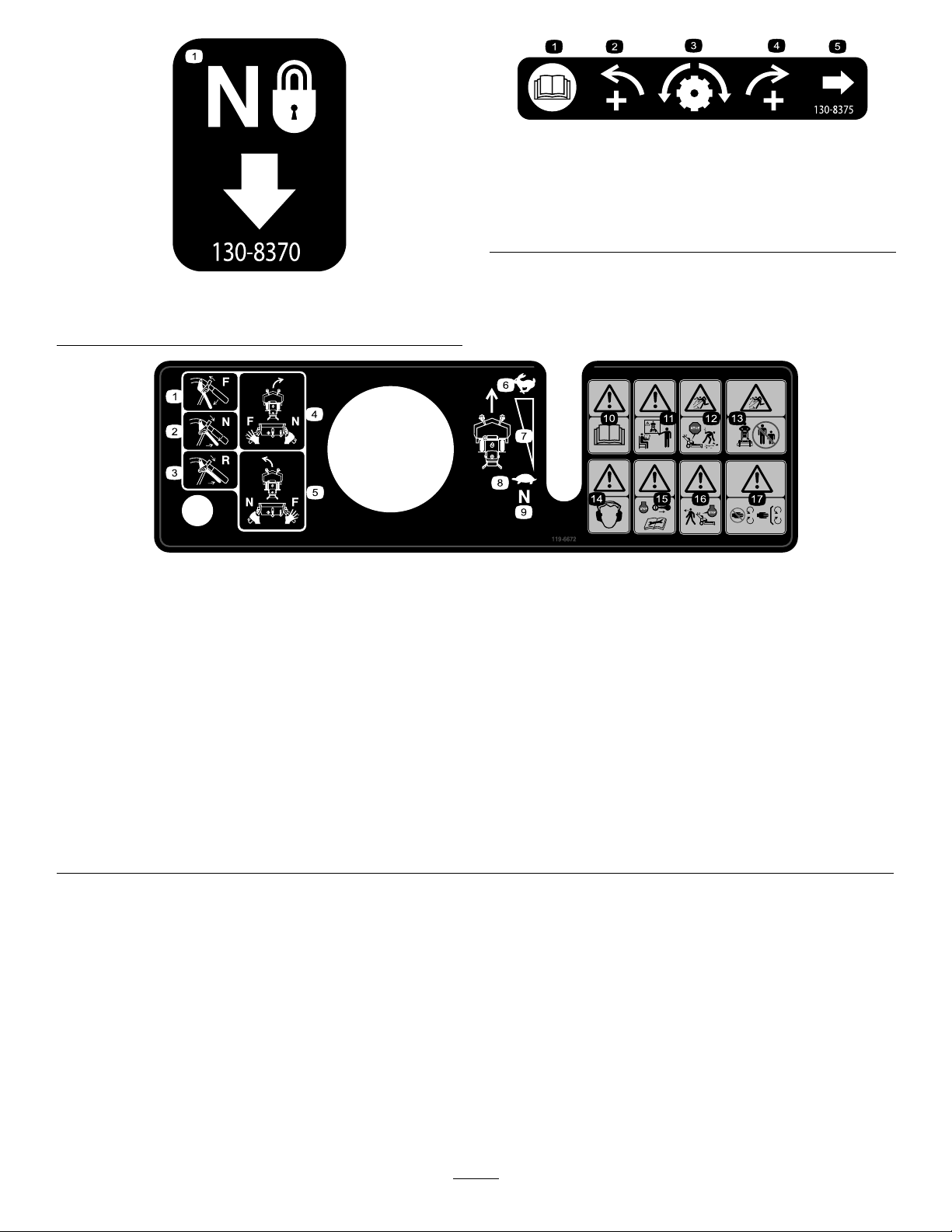
decal130-8375
130-8375
1.ReadtheOperator's
4.Increaseright
Manual.
2.Increaseleft
5.Trackingadjustmentknob
3.Trackingadjustment
decal130-8370
130-8370
1.Neutrallock
119-6672
1.Forward
2.Neutral11.Warning—donotoperatethismachineunlessyouaretrained.
3.Reverse
4.Toturnthemachineright,engageNEUTRALontherighthandle
whilethelefthandleisintheFORWARDposition.
5.Toturnthemachineleft,engageNEUTRALonthelefthandle
whiletherighthandleisintheFORWARDposition.
6.Fast
7.Continuous-variablesetting16.Warning—shutofftheenginebeforeleavingthemachine.
8.Slow17.Cutting,dismembermenthazardofhand—stayawayfrom
9.Neutral
10.Warning—readtheOperator'sManual.
12.Thrownobjecthazard—shutofftheenginebeforeclearing
debris.
13.Thrownobjecthazard—keepbystandersasafedistance
awayfromthemachine.
14.Warning—wearearprotection.
15.Warning—shutofftheengineandremovethekeybefore
performinganymaintenanceonthemachine.
movingparts,keepallguardsandshieldsinplace.
decal119-6672
7
Page 8

Setup
LooseParts
Usethechartbelowtoverifythatallpartshavebeenshipped.
ProcedureDescription
1
2
3
Note:Determinetheleftandrightsidesofthemachinefromthenormaloperatingposition.
Nopartsrequired
WheelKit(soldseparately)
Operator'sManual
Engineowner’smanual1
Operatortrainingmaterial
Oil-drainhose
1
CheckingtheFluidsand TirePressure
ReadingtheManualand
ViewingtheOperator
Qty.
–
1InstalltheWheelKit.
1
1
1
3
TrainingMaterial
NoPartsRequired
Use
Checktheuidsandtirepressure.
ReadtheOperator'sManualandwatch
theoperatortrainingmaterialbefore
operatingthemachine.
Procedure
•Beforeyoustarttheengineandusethemachine,
checktheoillevelintheenginecrankcase;refer
toCheckingtheEngine-OilLevel(page23).
•Checkthegreaseforthemachineandmower
deck.
Note:Thecuttingbladesaresettoa51mm(2inch)
heightofcutatinitialpurchase.TheaxlepositionisB,
with2spacesbelowthecastersand4spacesbelow
thespindle.
2
InstallingtheWheelKit
Partsneededforthisprocedure:
1
WheelKit(soldseparately)
Partsneededforthisprocedure:
1
Operator'sManual
1Engineowner’smanual
1
Operatortrainingmaterial
1
Oil-drainhose
Procedure
•ReadtheOperator'sManual.
•Viewtheoperatortrainingmaterialbefore
operatingthemachine.Thisisgeneraltraining
materialandthemachinemaydifferfromthat
supplied.
•Usetheoil-drainhosewhenchangingtheengine
oil.
Procedure
RefertotheInstallationInstructionsforthewheelkit
8
Page 9
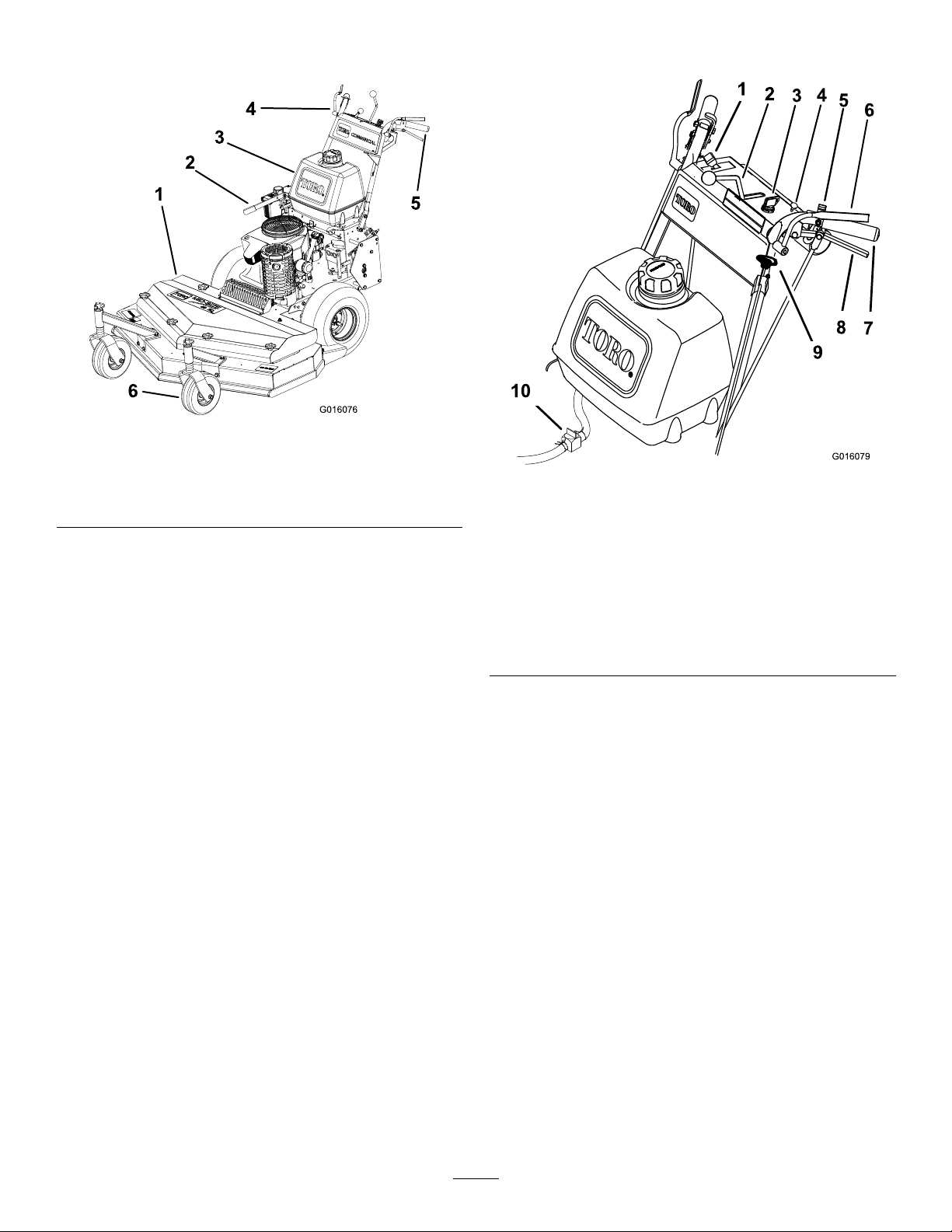
ProductOverview
g016076
Figure4
ControlPanel
1.Mowerdeck
2.Brake5.Handle
3.Fueltank
4.Controls
6.Casterwheel
Controls
Becomefamiliarwithallthecontrols(Figure5)before
youstarttheengineandoperatethemachine.
Figure5
1.Throttlecontrol
2.Speed-controllever
3.Keyswitch8.DriveLever
4.Choke9.Blade-controlknob(PTO)
5.Neutrallock
6.Operator-presencecontrol
(OPC)levers
7.Handle
10.Fuel-shutoffvalve
ThrottleControl
Thethrottlecontrolstheenginespeedandhas2
positions:SLOWandFAST.
Operator-PresenceControl(OPC)
Levers
WhenyousqueezetheOPCleversagainstthe
handles,theOPCsystemsensesthatyouareinthe
normaloperatingposition.Whenyoureleasethe
OPClevers,theOPCsystemsensesthatyouhave
leftthenormaloperatingposition,andthesystem
shutsofftheengineifeitherthespeed-controllever
isnotintheNEUTRALpositionortheblade-control
(PTO)knobisengaged.
g016079
9
Page 10

Blade-ControlKnob(PTO)
Specications
Usetheblade-controlknob(PTO),withtheOPC
leverspressedagainstthehandles,toengageand
disengagethedrivebelttodrivethemowerblades.
Pulltheknobuptoengagethebladesandpushdown
todisengagetheblades.
KeySwitch
Thisswitchisusedinconjunctionwithrecoilstarter
andhas3positions:OFF,RUN,andSTART.
Speed-ControlLever
Thismachinehasavariablespeedcontrolwitha
NEUTRALposition.Thiscontrolshowfastthemachine
travels.
DriveLevers
Releasethedriveleverstodrivethemachineforward;
squeezetheleversuntilyoufeelanincreaseinforce
togointotheNEUTRALpositionandthencontinue
tosqueezethemtodrivethemachineinreverse.
Squeezetherightdrivelevertoturnrightandsqueeze
theleftlevertoturnleft.
NeutralLock
Squeezethedriveleversuntilyoufeelanincreasein
forceandmovelockstotherearforneutrallock.
Note:Specicationsanddesignaresubjectto
changewithoutnotice.
82cm(32inch)mowerdecks:
Cuttingwidth82cm(32inches)
Width
Length
Height
Weight
89cm(35inches)
203cm(80inches)
112cm(44inches)
231kg(509lb)
91cm(36inch)mowerdecks:
Cuttingwidth91cm(36inches)
Width
Length
Height
Weight
94cm(37inches)
203cm(80inches)
112cm(44inches)
232kg(511lb)
122cm(48inch)mowerdecks:
Cuttingwidth122cm(48inches)
Width
Length
Height
Weight
126cm(49-1/2inches)
194cm(76-1/2inches)
112cm(44inches)
248kg(547lb)
Fuel-ShutoffValve
Closethefuel-shutoffvalvewhentransportingor
storingthemachine.
ChokeControl
Usethechokecontroltostartacoldengine.
Attachments/Accessories
AselectionofT oroapprovedattachmentsand
accessoriesisavailableforusewiththemachineto
enhanceandexpanditscapabilities.Contactyour
AuthorizedServiceDealerorDistributororgoto
www.T oro.comforalistofallapprovedattachments
andaccessories.
Toensureoptimumperformanceandcontinuedsafety
certicationofthemachine,useonlygenuineT oro
replacementpartsandaccessories.Replacement
partsandaccessoriesmadebyothermanufacturers
couldbedangerous,andsuchusecouldvoidthe
productwarranty.
10
Page 11

Operation
AddingFuel
FuelSafety
•Toavoidpersonalinjuryorpropertydamage,use
extremecareinhandlingfuel.Fuelvaporsare
ammableandexplosive.
•Extinguishallcigarettes,cigars,pipes,andother
sourcesofignition.
•Useonlyanapprovedfuelcontainer.
•Donotremovethefuelcaporaddfueltothefuel
tankwhiletheengineisrunningorwhilehot.
•Donotrefuelthemachineindoors.
•Donotstorethemachineorfuelcontainerwhere
thereisanopename,spark,orpilotlight,such
asonawaterheateroronotherappliances.
•Donotllcontainersinsideavehicleoronatruck
ortrailerbedwithaplasticliner.Alwaysplace
containersontheground,awayfromyourvehicle
beforelling.
•Removetheequipmentfromthetruckortrailer
andrefuelitwhileitisontheground.Ifthisisnot
possible,thenrefuelfromaportablecontainer
ratherthanafuel-dispensernozzle.
•Donotoperatethemachinewithouttheentire
exhaustsysteminplaceandinproperworking
condition.
•Keepthefuel-dispensernozzleincontactwith
therimofthefueltankorcontaineropeningat
alltimesuntilfuelingiscomplete.Donotusea
nozzlelock-opendevice.
•Ifyouspillfuelonyourclothing,changeyour
clothingimmediately.Wipeupanyfuelthatspills.
•Neveroverllthefueltank.Replacethefuelcap
andtightenitsecurely.
RecommendedFuel
•Forbestresults,useonlyclean,fresh(lessthan
30daysold),unleadedgasolinewithanoctane
ratingof87orhigher((R+M)/2ratingmethod).
•Ethanol:Gasolinewithupto10%ethanol
(gasohol)or15%MTBE(methyltertiarybutyl
ether)byvolumeisacceptable.Ethanoland
MTBEarenotthesame.Gasolinewith15%
ethanol(E15)byvolumeisnotapprovedforuse.
Neverusegasolinethatcontainsmorethan
10%ethanolbyvolume,suchasE15(contains
15%ethanol),E20(contains20%ethanol),orE85
(containsupto85%ethanol).Usingunapproved
gasolinemaycauseperformanceproblemsand/or
enginedamagewhichmaynotbecoveredunder
warranty.
•Donotusegasolinecontainingmethanol.
•Donotstorefueleitherinthefueltankorfuel
containersoverthewinterunlessyouuseafuel
stabilizer.
•Donotaddoiltogasoline.
UsingStabilizer/Conditioner
Usefuelstabilizer/conditionerinthemachinetokeep
thefuelfreshlongerwhenusedasdirectedbythe
fuel-stabilizermanufacturer.
Important:Donotusefueladditivescontaining
methanolorethanol.
Addtheamountoffuelstabilizer/conditionertofresh
fuelasdirectedbythefuel-stabilizermanufacturer.
FillingtheFuelTank
1.Parkthemachineonalevelsurface.
2.Engagetheparkingbrake.
3.Shutofftheengineandremovethekey.
4.Cleanaroundthefuel-tankcap.
•Storefuelinanapprovedcontainerandkeepit
outofthereachofchildren.Neverbuymorethan
a30-daysupplyoffuel.
•Donotllthefueltankcompletelyfull.Addfuelto
thefueltankuntilthelevelis6to13mm(1/4to
1/2inch)belowthebottomofthellerneck.This
emptyspaceinthetankallowsfueltoexpand.
–Avoidprolongedbreathingofvapors.
–Keepyourfaceawayfromthenozzleandfuel
tankopening.
–Avoidcontactwithskin;washoffspillswith
soapandwater.
5.Fillthefueltankuntilthelevelis6to13mm(1/4
to1/2inch)belowthebottomofthellerneck.
Note:Thisspaceinthetankallowsthefuelto
expand.Donotllthefueltankcompletelyfull.
6.Installthefueltankcapsecurely.Wipeupany
fuelthatmayhavespilled.
11
Page 12
ThinkSafetyFirst
Carefullyreadallthesafetyinstructionsanddecals
inthesafetysection.Knowingthisinformationcould
helpyouoranybystandersavoidinjury.
CAUTION
Thismachineproducessoundlevelsin
excessof85dBAattheoperator'searand
cancausehearinglossthroughextended
periodsofexposure.
Wearhearingprotectionwhenoperatingthis
machine.
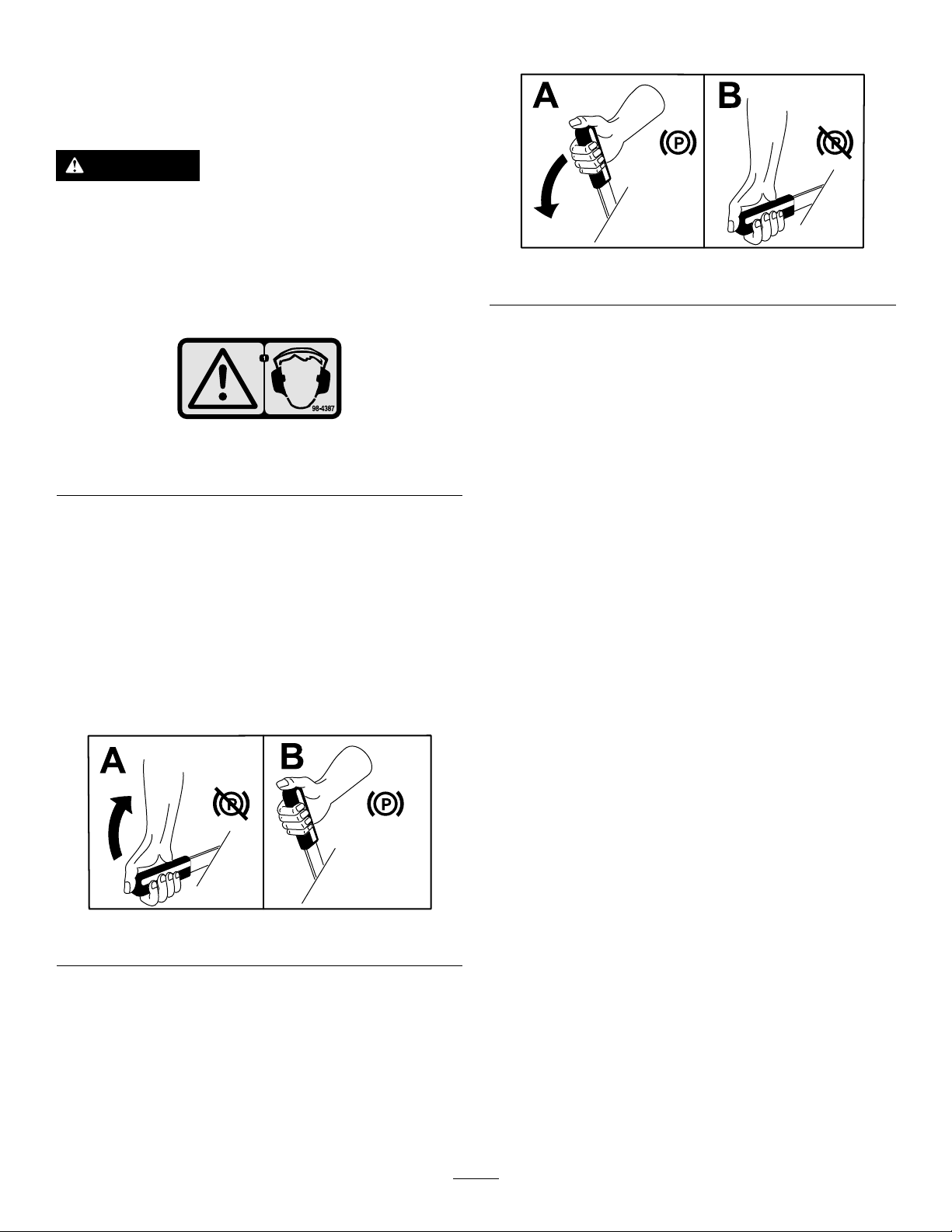
DisengagingtheParkingBrake
g241312
Figure8
StartingtheEngine
1.Connectthewirestothesparkplugs.
Figure6
1.Warning—wearhearingprotection.
OperatingtheParking Brake
Alwaysengagetheparkingbrakewhenyoustopthe
machineorleaveitunattended.
EngagingtheParkingBrake
Parkthemachineonalevelsurface.
decal98-4387
2.Openthefuelvalve.
3.Disengagetheblade-controlknob(PTO)and
movethespeed-controllevertotheNEUTRAL
position.
4.MovethedriveleverstotheNEUTRALposition
andengagetheneutrallocks.
5.Engagetheparkingbrake.
6.TurnthekeytotheRUNposition(Figure5).
7.Tostartacoldengine,movethethrottlecontrol
midwaybetweentheFASTandSLOWpositions.
8.Tostartawarmengine,movethethrottlecontrol
totheFASTposition.
9.Engagethechokeiftheengineiscold(Figure
5).
Note:Awarmorhotengineusuallydoesnot
requireanychoking.
10.TurnthekeytotheST ARTpositiontoenergize
thestarter.Whentheenginestarts,releasethe
key.
Figure7
Note:Donotengagethestarterformorethan
5secondsatatime.Iftheenginefailstostart,
g241313
12
allowfora15secondcool-downperiodbetween
attempts.Failuretofollowtheseinstructionscan
burnoutthestartermotor.
11.Disengagethechokeastheenginewarmsup
(Figure9).
12.Iftheengineiscold,allowittowarmupandthen
movethethrottlecontroltotheFASTposition.
Page 13
ShuttingOfftheEngine
Important:Inanemergency,youcanshutoff
theengineimmediatelybyturningthekeytothe
OFFposition.
1.MovethedriveleverstotheNEUTRALposition
andengagetheneutrallocks.
2.MovethethrottlelevertotheSLOW(Figure9).
3.Disengagetheblade-controlknob(PTO)and
movethespeed-controllevertotheNEUTRAL
position.
4.Lettheengineidlefor30to60seconds
2.Placeyourthumbsontheupperpartofthelocks
andmovethembackuntilthepinsareinthe
NEUTRALposition(Figure10).
5.TurnthekeytotheOFFposition.
6.Engagetheparkingbrakeandremovethekey.
Important:Closethefuel-shutoffvalve
beforetransportingorthestoringthe
machinetopreventfuelleakage.
Figure10
1.Handle4.Drivelever
2.Neutrallock
3.NEUTRALposition6.REVERSEposition
5.Fullspeedforward
ReleasingtheNeutralLock
1.Squeezethedriveleversuntilyoufeelan
increaseinforce.
2.Placeyourthumbsontheupperpartoflocks
andmovethemforwarduntilthepinsareinthe
forwardslot(Figure11).
g001508
Figure9
1.Throttlelever
2.Keyswitch
3.Choke
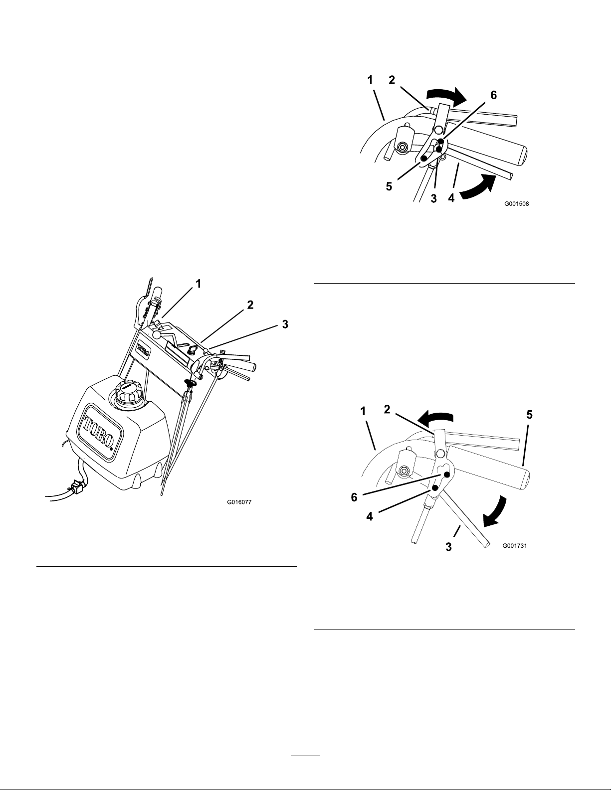
OperatingtheNeutral Locks
Alwaysengagetheneutrallockwhenyoustop
themachine.Engagetheparkingbrakeifitisleft
unattended.
SettingtheNeutralLock
1.Squeezethedriveleversuntilyoufeelan
increaseinforce.
g027797
g001731
Figure11
1.Handle
2.Neutrallock5.Handle
3.Drivelever6.Forwardslot
13
4.Pininfullspeedforward
Page 14
Operatingthe
UsingtheSafety-Interlock
Blade-ControlKnob(PTO)
Theblade-controlknob(PTO)isusedinconjunction
withtheoperator-presencecontrol(OPC)leversto
engageanddisengagethemowerblades.
EngagingtheMowerBlades(PTO)
1.Toengagethemowerblades,squeezethe
operator-presencecontrol(OPC)leversagainst
handlegrips(Figure12).
2.Pulltheblade-controlknob(PTO)up.Holdthe
OPCleversagainsthandlegrip.
Note:ReleasingtheOPCleverswiththe
mowerbladesrunningshutsofftheengine.
3.Starttheengineandrepeattheprocedure
toengagethemowerbladesifthe
operator-presencecontrol(OPC)levers
arereleased.
System
CAUTION
Ifsafety-interlockswitchesaredisconnected
ordamagedthemachinecouldoperate
unexpectedlycausingpersonalinjury.
•Donottamperwiththeinterlockswitches.
•Checktheoperationoftheinterlock
switchesdailyandreplaceanydamaged
switchesbeforeoperatingthemachine.
Understandingthe Safety-InterlockSystem
Thesafety-interlocksystemisdesignedtopreventthe
machinefromstartingunless:
•Theblade-controlknob(PTO)isdisengaged.
•Thespeed-controlleverisintheNEUTRALposition.
Thesafety-interlocksystemisdesignedtoshutoff
theenginewhen:
Figure12
1.Throttlelever4.DriveLever
2.Operator-presencecontrol
(OPC)levers
3.Handle
5.Blade-controlknob(PTO)
DisengagingtheMowerBlades (PTO)
Themowerbladescanbedisengagedby2ofthe
followingsteps.
1.Pushtheblade-controlknob(PTO)downtothe
OFFposition(Figure12).
2.Releasingtheoperator-presencecontrol(OPC)
leversshutsofftheengineandstopstheblades
(Figure12)withtheblade-controlleverengaged.
•Theoperator-presencecontrol(OPC)levers
arereleasedwiththemowerbladesengaged
and/orthespeed-controlleveroutoftheNEUTRAL
position.
•Thespeed-controlleverisshiftedoutofthe
NEUTRALwithoutholdingOPCleversorwiththe
brakeengaged.
•Theblade-controlknob(PTO)ispulledupwithout
holdingtheOPClevers.
g016110
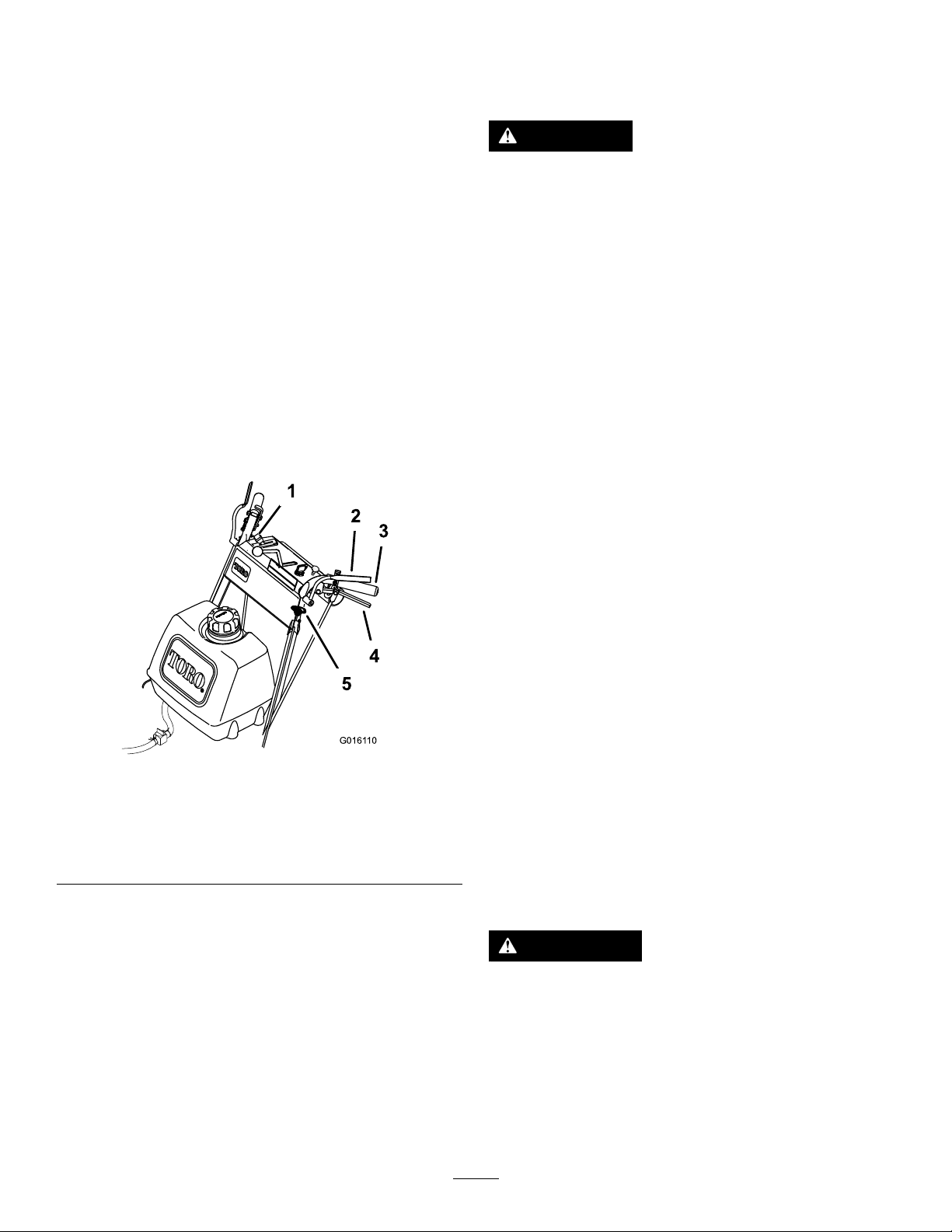
TestingtheSafety-Interlock System
ServiceInterval:Beforeeachuseordaily
Testthesafety-interlocksystembeforeyouusethe
machineeachtime.Ifthesafetysystemdoesnot
operateasdescribed,haveanAuthorizedService
Dealerrepairthesafetysystemimmediately.
WARNING
Whiletestingthesafety-interlocksystem,
themachinemaymoveforwardandcause
personalinjuryorpropertydamage.
•Testthesafety-interlocksysteminanopen
area.
•Ensurethatnooneisstandingin
frontofthemachinewhiletestingthe
safety-interlocksystem.
14
Page 15
1.Engagetheneutrallocksandmovethe
speed-controllevertotheNEUTRALposition.
2.Starttheengine;refertoStartingtheEngine
(page12).
3.Withoutholdingtheoperator-presencecontrol
(OPC)levers,pulltheblade-controlknob(PTO)
up.Theengineshouldshutoff.
4.Disengagetheblade-controlknob(PTO).
5.Withenginerunning,holddowntheOPClevers.
Pulltheblade-controlknob(PTO)up.Thedrive
beltshouldengageandthemowerbladesbegin
rotating.
6.ReleasetheOPClevers.Theengineshould
shutoff.
7.Withtheenginerunning,movethespeed-control
leverforward.ReleasetheOPClevers.The
engineshouldshutoff.
1.Drivelever
g01611 1
Figure13
2.Speed-controllever
8.Ifalltheaboveconditionsarenotmethave
anAuthorizedServiceDealerrepairthesafety
systemimmediately.
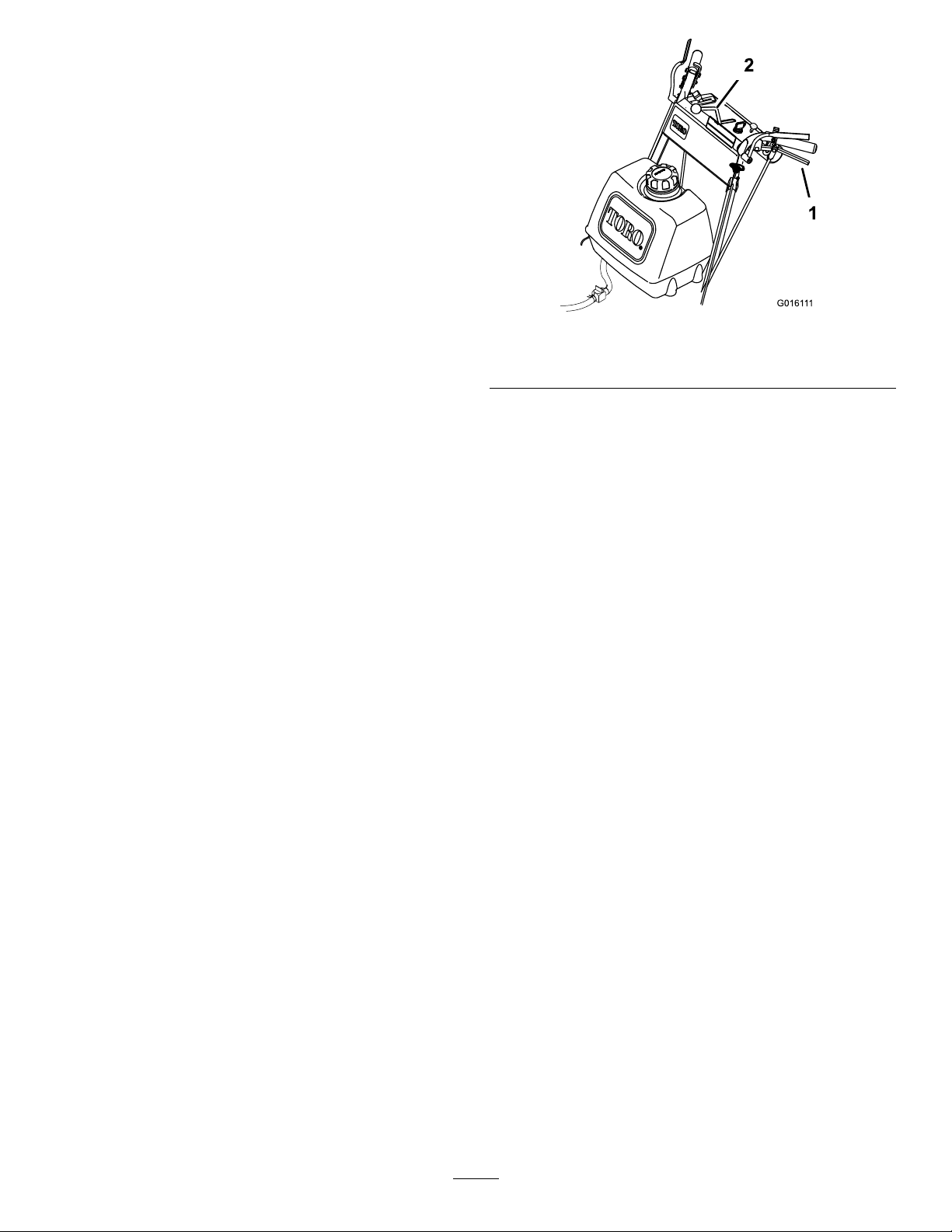
DrivingtheMachine ForwardandBackward
Thethrottlecontrolregulatestheenginespeedas
measuredinrpm(revolutionsperminute).Placethe
throttlecontrolintheFASTpositionforbestmowing
performance.
DrivingForward
1.Disengagetheparkingbrake.
2.Movethespeed-controllevertodesiredspeed.
3.Releasetheneutrallock.RefertoReleasingthe
NeutralLock(page13).
4.Slowlyreleasethedriveleverstomoveforward
(Figure13).
Togostraight,releasedriveleversequally
(Figure13).
Toturn,squeezethedriveleveronthesideand
directionyouwanttoturn(Figure13).
DrivingBackward
Slowlysqueezethedriveleverstothehandletomove
rearward(Figure13).
BringingtheMachineto Neutral
Alwaysengagetheneutrallockandparkingbrake
whenyoustopthemachine.
1.SqueezethedriveleverstotheNEUTRAL
position.
2.Engagetheneutrallocks.RefertoOperating
theNeutralLocks(page13).
3.Movethespeed-controllevertotheNEUTRAL
position.
PushingtheMachineby Hand
Thebypassvalvesenableyoutopushthemachine
byhandwithouttheenginerunning.
Important:Alwayspushthemachinebyhand.
Nevertowthemachine,becausehydraulic
damagemayoccur.
ToPushtheMachine
1.Parkthemachineonalevelsurface,disengage
thePTO,andengagetheparkingbrake.
2.Shutofftheengine,removethekey,andwait
forallmovingpartstostopbeforeleavingthe
operatingposition.
15
Page 16

3.Openthebypassvalvesbyturningthemcounter
clockwise1to2times(Figure14).
Note:Thisallowshydraulicuidtobypassthe
pumpsandthewheelstoturn.
4.Disengagetheparkingbrake.
5.Pushthemachinetothedesiredlocation.
6.Engagetheparkingbrake.
7.Closethebypassvalvesbutdonotovertighten
them.
Note:Rotatethebypassvalvesamaximumof
2turnssothevalvedoesnotcomeoutofthe
bodyandcauseuidtorunout.
heightofcut.RefertoHeight-of-CutChart(page19)
toselectthecombinationofadjustmentsrequired.
AdjustingtheBladeHeight
Adjustthebladesbyusingthe4spacers(1/4inch)
spacersonthebladespindlebolts.Thisallowsfora
25mm(1inch)adjustmentrangeofcuttingheight,in
6mm(1/4inch)increments,inanyaxleposition.Use
thesamenumberofbladespacersonallbladesto
achievealevelcut(2aboveand2below,1above
and3below,etc.).
1.Parkthemachineonalevelsurface,disengage
thePTO,andengagetheparkingbrake.
Important:Donotstartoroperatethe
machinewiththebypassvalvesopen.
Damagetosystemmayoccur.
Figure14
1.Hydraulicpump2.Bypassvalve
TransportingtheMachine
Useaheavy-dutytrailerortrucktotransportthe
machine.Ensurethatthetrailerortruckhasall
necessarylightingandmarkingasrequiredbylaw.
Pleasecarefullyreadallthesafetyinstructions.
Knowingthisinformationcouldhelpyou,yourfamily,
petsorbystandersavoidinjury.
2.Shutofftheengine,removethekey,andwait
forallmovingpartstostopbeforeleavingthe
operatingposition.
3.Holdthebladeboltandremovethenut.Slide
theboltdownthroughthespindle,andchange
thespacersasneeded(Figure15).
g007735
1.Secureatrailertotowingvehiclewithsafety
chains.
2.Shutofftheengine,removethekey,andwait
forallmovingpartstostopbeforeleavingthe
operatingposition.
3.Securelyfastenthemachinetothetraileror
truckwithstraps,chains,cable,orropes.
AdjustingtheHeightofCut
Thismachinehasa26to108mm(1to4-1/4inch)
rangeforheightofcut.Adjustthebladespacers,rear
axleheightorfrontcasterspacerstogetthecorrect
1.Blade
2.Bladebolt5.Thinwasher
3.Curvedwasher
16
g001454
Figure15
4.Spacer
6.Nut
Page 17

4.Installthebolt,curvedwasher,blade,addextra
spacers,andsecurethemwithathinwasher
andanut(Figure15).
5.Torquethebladeboltto101to108N∙m(75to
80ft-lb).
AdjustingtheAxleHeight
Adjusttheaxlepositiontotheselectedheight-of-cut
setting.RefertoHeight-of-CutChart(page19).
1.Parkthemachineonalevelsurface,disengage
thePTO,andengagetheparkingbrake.
2.Shutofftheengine,removethekey,andwait
forallmovingpartstostopbeforeleavingthe
operatingposition.
3.Placeajackundertheengineframe.Raisethe
backendoftheengineframeenoughtoremove
thedrivewheels.
4.Removethedrivewheels.
5.Loosen,butdonotremove,the2topaxlebolts
(Figure16).
6.Removethe2loweraxlebolts(Figure16).
AdjustingtheCaster Position
1.Adjustthecasterspacerstomatchwiththeaxle
holeselected(Figure17);refertoHeight-of-Cut
Chart(page19)and.
Figure17
1.Latchpin
2.Spacer—5mm(3/16inch)
3.Spacer—13mm(1/2inch)
g001456
Figure16
1.Topaxlebolt2.Loweraxlebolt
7.Raiseorlowerthemountingbracket,sothat
youcaninstallthe2axleadjustmentboltsinthe
desiredholelocation(Figure16).
Note:Ataperedpunchcanbeusedtohelp
aligntheholes.
2.Removethelatchpin,slidethecasterfromthe
support,andchangethespacers(Figure17).
3.Installthecasterinthesupportandinsertthe
latchpin(Figure17).
g001512
8.Tightenall4bolts.
9.Installthedrivewheelsandlowerthemachine.
17
Page 18

AdjustingtheHandle Height
Thehandlepositioncanbeadjustedtomatchyour
heightpreference.
1.Removethehairpincottersandclevispinsfrom
thedriveleversandneutrallocks(Figure18).
g001734
Figure19
Figure18
1.Controlrod5.Lefthandleshown
2.Clevispin
3.Drivelever7.Hairpincotter
4.Operator-presencecontrol
lever(OPC)
6.Neutrallock
2.Loosentheupperangebolts(3/8x1-1/4
inches)andangenutsecuringhandletorear
frame(Figure19).
3.Removethelowerangebolts(3/8x1inch)
andangenutssecuringhandletorearframe
(Figure19).
4.Pivothandletodesiredoperatingpositionand
installlowerangebolts(3/8x1inch)andange
nutsintomountingholes.Tightenallange
bolts.
1.Controlrodtting
2.Lowermountingholes7.Lowerposition
3.Rearframe
g001733
4.Lowerangebolt(3/8x1
inch)
5.Upperangebolt(3/8x
1-1/4inches)
6.Highposition
8.Uppermountinghole
9.Handle
10.Flangenut(3/8inch)
5.Adjustthecontrolrodlengthbyrotatingthe
controlrodintherodtting(Figure18and
Figure19).
6.Installhairpincotterbetweendriveleversand
neutrallocksandintoclevispins(Figure18).
Note:Makesurethattheclevispinsare
insertedintotheneutrallocks.
7.Performthehydrauliclinkageadjustmentswhen
thehandleheightischanged;referAdjustingthe
HydraulicControlLinkages(page30).
18
Page 19

Height-of-CutChart
Numberofspacers
Axle
Position
A00
A01
A10
B01
B10
B11
B20
C
C
C
C
D21
D30
D31
D40
E31
E40
E41
belowcaster
13mm5mm
(1/2inch)(3/16inch)
11
20
21
30
Numberof6mm(1/4inch)bladespacersbelowspindle
43210
26mm32mm38mm45mm51mm
(1inch)(1-1/4inch)(1-1/2inch)(1-3/4inch)(2inch)
29mm35mm41mm48mm54mm
(1-1/8inch)(1-3/8inch)(1-5/8inch)(1-7/8inch)(2-1/8inch)
35mm41mm48mm54mm60mm
(1-3/8inch)(1-5/8inch)(1-7/8inch)(2-1/8inch)(2-3/8inch)
35mm41mm48mm54mm60mm
(1-3/8inch)(1-5/8inch)(1-7/8inch)(2-1/8inch)(2-3/8inch)
41mm48mm54mm60mm67mm
(1-5/8inch)(1-7/8inch)(2-1/8inch)(2-3/8inch)(2-5/8inch)
45mm51mm
(1-3/4inch)(2inch)(2-1/4inch)(2-1/2inch)(2-3/4inch)
51mm
(2inch)(2-1/4inch)(2-1/2inch)(2-3/4inch)(3inch)
48mm54mm60mm67mm73mm
(1-7/8inch)(2-1/8inch)(2-3/8inch)(2-5/8inch)(2-7/8inch)
54mm60mm67mm73mm79mm
(2-1/8inch)(2-3/8inch)(2-5/8inch)(2-7/8inch)(3-1/8inch)
57mm
(2-1/4inch)(2-1/2inch)(2-3/4inch)(3inch)(3-1/4inch)
64mm70mm76mm83mm89mm
(2-1/2inch)(2-3/4inch)(3inch)(3-1/4inch)(3-1/2inch)
60mm67mm73mm79mm86mm
(2-3/8inch)(2-5/8inch)(2-7/8inch)(3-1/8inch)(3-3/8inch)
64mm70mm76mm83mm89mm
(2-1/2inch)(2-3/4inch)(3inch)(3-1/4inch)(3-1/2inch)
70mm76mm83mm89mm95mm
(2-3/4inch)(3inch)(3-1/4inch)(3-1/2inch)(3-3/4inch)
76mm83mm89mm95mm102mm
(3inch)(3-1/4inch)(3-1/2inch)(3-3/4inch)(4inch)
73mm79mm86mm92mm98mm
(2-7/8inch)(3-1/8inch)(3-3/8inch)(3-5/8inch)(3-7/8inch)
79mm86mm92mm98mm105mm
(3-1/8inch)(3-3/8inch)(3-5/8inch)(3-7/8inch)(4-1/8inch)
83mm89mm95mm102mm108mm
(3-1/4inch)(3-1/2inch)(3-3/4inch)(4inch)(4-1/4inch)
57mm
64mm70mm76mm83mm
57mm
64mm70mm76mm
64mm70mm
19
Page 20

Maintenance
Note:Determinetheleftandrightsidesofthemachinefromthenormaloperatingposition.
RecommendedMaintenanceSchedule(s)
MaintenanceService
Interval
Aftertherst8hours
Aftertherst25hours
Beforeeachuseordaily
Every25hours
Every50hours
MaintenanceProcedure
•Changetheengineoil.
•Checkthemowerbelttension.
•Checkthehydraulic-uidlevel.
•Replacethehydraulicuidlter.
•Checkthemowerbelttension.
•Checkthesafetysystem.
•Greasethecasterwheelsandcasterpivot.
•Checktheengine-oillevel.
•Cleantheairintakescreen.
•Checktheparkingbrake.
•Inspecttheblades.
•Cleanthemowerdeck.
•Cleanthefoamair-cleanerelement(moreoftenindirtyordustyconditions).
•Checkthehydraulic-uidlevel.
•Greasethemower-beltidler .
•Greasethepump-driveidlerpivot.
•Greasethepumpcontrol.
•Checkthepaperair-cleanerelement(moreoftenindirtyordustyconditions).
•Checkthetirepressure.
•Checkthebelts.
•Checkthemowerbelttension.
•Greasetheblade-engagementbellcrank.
Every100hours
Every200hours
Every300hours
Every400hours
Beforestorage
•Changetheengineoil(moreoftenindirtyordustyconditions).
•Replaceorcleanandgapthesparkplug.
•Checkhydrauliclinesandhoses.
•Replacethepaperair-cleanerelement(moreoftenindirtyordustyconditions).
•Changetheengine-oillter(moreoftenindirtyordustyconditions).
•Replacethefuellter.
•Replacethehydraulicuidlter.
•Checkandadjustthevalveclearance.SeeanAuthorizedServiceDealer.
•Lubricatethecamlockwithanti-seizecompound.
•Paintchippedsurfaces.
•Performallmaintenanceprocedureslistedabovebeforestorage.
Important:Refertotheengineowner’smanualforadditionalmaintenanceprocedures.
CAUTION
Ifyouleavethekeyintheswitch,someonecouldaccidentlystarttheengineandseriously
injureyouorotherbystanders.
Removethekeyfromtheswitchbeforeyouperformanymaintenance.
20
Page 21

Lubrication
GreasingthePumpControl
UseFigure20forlocatingthegreasepointsonthe
machine.
Greasetype:No.2lithiumormolybdenumgrease
1.Parkthemachineonalevelsurface,disengage
thePTO,andengagetheparkingbrake.
2.Shutofftheengine,removethekey,andwait
forallmovingpartstostopbeforeleavingthe
operatingposition.
3.Cleanthegreasettingswitharag.Scrapeany
paintoffthefrontofthetting(s).
4.Connectagreaseguntothetting.Pump
greaseintothettingsuntilgreasebeginsto
oozeoutofthebearings.
5.Wipeupanyexcessgrease.
LubricatingtheCasterand WheelBearings
ServiceInterval:Beforeeachuseordaily
andBellCrank
ServiceInterval:Every50hours—Greasethe
pump-driveidlerpivot.
Every50hours—Greasethepumpcontrol.
Every100hours—Greasethe
blade-engagementbellcrank.
Every400hours—Lubricatethecamlockwith
anti-seizecompound.
Greasethettingonthepump-driveidlerpivotand
thepumpcontrol.
Greasethebladeengagement(PTO)bellcrank
(Figure20).
Lubricatecamlockwithanti-seizecompound.
Note:Removetheguardsttedunderthemachineto
accessthegreasettingonthepump-driveidlerpivot.
Lubricatethefrontwheelbearingsandfrontspindles
(Figure20).
GreasingtheMower-Belt Idler
ServiceInterval:Every50hours
Greasethettingonthemower-beltidlerarmpivot
(Figure20).
Note:Removethemowerdeckcovertoaccessthe
greasettingforthemower-beltidlerarm.
Figure20
1.Pump-driveidlerarm4.Mowerbeltidlerarm
2.Pumpcontrolarm
3.Bellcrank
5.Casterwheelbearing
6.Casterpivot
g001514
21
Page 22

EngineMaintenance
CleaningtheFoamAir-Cleaner Element
ServicingtheAirCleaner
ServiceInterval:Every25hours(moreoftenindirty
ordustyconditions).
Every50hours(moreoftenindirtyordusty
conditions).
Every200hours/Yearly(whichevercomesrst)
(moreoftenindirtyordustyconditions).
Inspectthefoamandpaperelementsandreplace
themiftheyaredamagedorexcessivelydirty .
Important:Donotoilthefoamorpaperelement.
RemovingtheFoamandPaper Elements
1.Parkthemachineonalevelsurface,disengage
thePTO,andengagetheparkingbrake.
2.Shutofftheengine,removethekey,andwait
forallmovingpartstostopbeforeleavingthe
operatingposition.
3.Cleanaroundtheaircleanertopreventdirtfrom
gettingintotheengineandcausingdamage
(Figure21).
4.Unscrewthecoverknobsandremovethe
air-cleanercover(Figure21).
5.Unscrewthehoseclampandremovethe
air-cleanerassembly(Figure21).
6.Carefullypullthefoamelementoffthepaper
element(Figure21).
1.Washthefoamelementinliquidsoapand
warmwater.Whentheelementisclean,rinse
itthoroughly.
2.Drytheelementbysqueezingitinacleancloth.
Important:Replacethefoamelementifit
istornorworn.
ServicingthePaperAir-Cleaner Element
1.Donotcleanthepaperlter.Replaceit(Figure
21).
2.Inspecttheelementfortears,anoilylm,or
damagetotherubberseal.
3.Replacethepaperelementifitisdamaged.
InstallingtheFoamandPaper Elements
Important:Topreventenginedamage,always
operatetheenginewiththecompletefoamand
paperair-cleanerassemblyinstalled.
1.Carefullyslidethefoamelementontothepaper
air-cleanerelement(Figure21).
2.Placetheair-cleanerassemblyontothe
air-cleanerbaseandsecureitwiththe2wing
nuts(Figure21).
3.Placetheair-cleanercoverintopositionand
tightenthecoverknob(Figure21).
Figure21
1.Cover
2.Hoseclamp4.Foamelement
3.Paperelement
g012352
22
Page 23

ServicingtheEngineOil
EngineOilSpecications
OilCapacity:withalterchange—1.7L(57oz);
withoutalterchange—1.5L(51oz)
Viscosity:Seethetablebelow.
Figure22
g017470
CheckingtheEngine-OilLevel
ServiceInterval:Beforeeachuseordaily
Note:Checktheoilwhentheengineiscold.
Important:Ifyouoverllorunderlltheengine
crankcasewithoilandruntheengine,youmay
damagetheengine.
1.Parkthemachineonalevelsurface,disengage
thePTO,andengagetheparkingbrake.
2.Shutofftheengine,removethekey,andwait
forallmovingpartstostopbeforeleavingthe
operatingposition.
Note:Ensurethattheengineiscoolsothatthe
oilhashadtimetodrainintothesump.
3.Tokeepdirt,grassclippings,etc.,outofthe
engine,cleantheareaaroundtheoil-llcapand
dipstickbeforeremovingit(Figure23).
g194611
Figure23
ChangingtheEngineOil
ServiceInterval:Aftertherst8hours—Changethe
engineoil.
Every100hours—Changetheengineoil(more
oftenindirtyordustyconditions).
1.Parkthemachinesothatthedrainsideisslightly
lowerthantheoppositesidetoensurethatthe
oildrainscompletely.
2.DisengagethePTOandengagetheparking
brake.
3.Shutofftheengine,removethekey,andwait
forallmovingpartstostopbeforeleavingthe
operatingposition.
4.Draintheoilfromtheengine(Figure24).
23
Page 24

Figure24
5.Slowlypourapproximately80%ofthespecied
oilintothellertubeandslowlyaddthe
additionaloiltobringittotheFullmark(Figure
25).
g194610
Figure25
6.Disposeoftheusedoilatarecyclingcenter.
g027476
24
Page 25

ChangingtheEngine-OilFilter
ServicingtheSparkPlug
ServiceInterval:Every200hours—Changethe
engine-oillter(moreoftenindirty
ordustyconditions).
1.Draintheoilfromtheengine;refertoChanging
theEngineOil(page23).
2.Changetheengine-oillter(Figure26).
ServiceInterval:Every100hours
Ensurethattheairgapbetweenthecenterandside
electrodesiscorrectbeforeinstallingthesparkplug.
Useasparkplugwrenchforremovingandinstalling
thesparkplugandagappingtoolorfeelergaugeto
checkandadjusttheairgap.Installanewsparkplug
ifnecessary .
TypeofSparkPlug:NGK
AirGap:0.75mm(0.03inch)
®
BPR4ESorequivalent
RemovingtheSparkPlug
1.Parkthemachineonalevelsurface,disengage
thePTO,andengagetheparkingbrake.
2.Shutofftheengine,removethekey,andwait
forallmovingpartstostopbeforeleavingthe
operatingposition.
3.Cleantheareaaroundthebaseoftheplugto
keepdirtanddebrisoutoftheengine.
4.Removethesparkplug(Figure27).
Figure26
Note:Ensurethattheoil-ltergaskettouches
theengine,andthenturntheoillteranextra
3/4turn.
3.Fillthecrankcasewiththepropertypeofnew
oil(Figure25).
g027478
Figure27
g027477
25
Page 26

CheckingtheSparkPlug
Important:Donotcleanthesparkplug(s).
Alwaysreplacethesparkplug(s)whenithasa
blackcoating,wornelectrodes,anoilylm,or
cracks.
Ifyouseelightbrownorgrayontheinsulator,the
engineisoperatingproperly.Ablackcoatingonthe
insulatorusuallymeanstheaircleanerisdirty .
Setthegapto0.75mm(0.03inch).
Figure28
FuelSystem
Maintenance
ServicingtheFuelTank
DANGER
Incertainconditions,fuelisextremely
ammableandhighlyexplosive.Areor
explosionfromfuelcanburnyouandothers
andcandamageproperty.
•Drainfuelfromthefueltankwhenthe
engineiscold.Dothisoutdoorsinanopen
area.Wipeupanyfuelthatspills.
•Neversmokewhendrainingfuel,andstay
g206628
awayfromanopenameorwhereaspark
mayignitethefuelfumes.
DrainingtheFuelTank
InstallingtheSparkPlug
Figure29
1.Parkthemachineonalevelsurface,disengage
thePTO,andengagetheparkingbrake.
2.Shutofftheengine,removethekey,andwait
forallmovingpartstostopbeforeleavingthe
operatingposition.
3.Closethefuel-shutoffvalveatthefueltank
(Figure30).
4.Squeezetheendsofthehoseclamptogether
andslideitupthefuellineawayfromfuellter
(Figure30).
5.Pullthefuellineoffthefuellter(Figure30).
Openthefuel-shutoffvalveandallowthefuelto
drainintoafuelcanordrainpan.
Note:Nowisthebesttimetoinstallanewfuel
lterbecausethefueltankisempty.Referto
g027661
ReplacingtheFuelFilter(page27).
6.Installthefuellineontothefuellter.Slidethe
hoseclampclosetothevalvetosecurethefuel
line.
26
Page 27

Figure30
g001467
1.Fuel-shutoffvalve2.Fuellter
ServicingtheFuelFilter
ReplacingtheFuelFilter
ServiceInterval:Every200hours/Yearly(whichever
comesrst)
Neverinstalladirtylterafterremovingitfromthe
fuelline.
1.Parkthemachineonalevelsurface,disengage
thePTO,andengagetheparkingbrake.
2.Shutofftheengine,removethekey,andwait
forallmovingpartstostopbeforeleavingthe
operatingposition.
3.Closefuel-shutoffvalveatthefueltank(Figure
30).
4.Squeezetheendsofthehoseclampstogether
andslidethemawayfromthelter(Figure31).
g001468
Figure31
1.Hoseclamp3.Filter
2.Fuelline
5.Removethelterfromthefuellines.
6.Installanewlterandmovethehoseclamps
closetothelter.
7.Openfuel-shutoffvalveatfueltank(Figure30).
8.Checkforfuelleaksandrepairifneeded.
9.Wipeupanyspilledfuel.
Note:Notehowthefuellterisinstalledin
ordertoinstallthenewltercorrectly.
27
Page 28

DriveSystem
Maintenance
Performthefollowinglinkageadjustments,Adjusting
theSpeed-ControlLinkage(page28)through
AdjustingtheTracking(page32),whenthemachine
needsmaintenance.Ifanyadjustmentisneeded,do
themintheorderthattheyarelisted.
Adjustingthe Speed-ControlLinkage
1.Parkthemachineonalevelsurface,disengage
thePTO,andengagetheparkingbrake.
2.Shutofftheengine,removethekey,andwait
forallmovingpartstostopbeforeleavingthe
operatingposition.
3.Movethespeed-controllever(locatedonthe
console)tothefullforwardposition.
4.Checktheorientationofthetabsontheends
ofthespeedcontrolcrank.Ensurethatthese
tabsarepointingstraightdownatthe6o'clock
positionapproximately(Figure32).
7.Checktomakesurethatthesafetyswitchis
pressedandthereisa8mm(5/16inch)space
betweentheactuatingtabandtheswitch(Figure
33).
8.Ifneeded,adjustswitchlocationtocreatethe
8mm(5/16inch)space(Figure33).
5.Adjustthethreadedyokeatthebottomofthe
speed-controllinkageuntilthetabsareatthe
6o'clockposition(Figure32).
Figure32
g007736
Figure33
1.Safetyswitch
2.8mm(5/16inch)space
g001516
3.Actuatingtab
1.Speedcontrolrod
2.Yoke5.Jamnut
3.Speedcontrolcrank
6.Pullthespeed-controlleverbacktotheNEUTRAL
position.
4.Tabs,6o'clockposition
28
Page 29

AdjustingtheNeutral ControlLinkages
WARNING
Theenginemustberunningwhenyou
performthecontrollinkageadjustments.
Contactwithmovingpartsorhotsurfaces
maycausepersonalinjury.
Keepyourhands,feet,face,clothingand
otherbodypartsawayfromrotatingparts,
muferandotherhotsurfaces.
WARNING
Mechanicalorhydraulicjacksmayfailto
supportmachineandcauseaseriousinjury.
•Usejackstandswhensupportingmachine.
•Donotusehydraulicjacks.
1.Parkthemachineonalevelsurface,disengage
thePTO,andengagetheparkingbrake.
2.Shutofftheengine,removethekey,andwait
forallmovingpartstostopbeforeleavingthe
operatingposition.
3.Raisetherearofthemachineontojackstands
toraisethedrivewheelsofftheground.
8.Squeeze1driveleveruntilyoufeelanincreased
resistance.ThisistheNEUTRALposition.
Note:Makesurethatyouhavenotreachedthe
endoftheneutrallockslot.Ifyouhave,shorten
thecontrolleverlinkage.RefertoAdjustingthe
ControlRod.
9.Ifthewheelturnswhileholdingthedriveleverin
theNEUTRAL,theneutralcontrollinkagesneed
adjustment(Figure34).Ifthewheelstopsthen
gotostep12.
10.Loosenthenutagainsttheneutralcontrol
linkageyoke(Figure34).
11.Adjusttheneutralcontrollinkageuntilthe
respectivedrivewheelstopswhilethedrivelever
ispulledagainsttheneutralspring(NEUTRAL
position)(Figure34).
12.Turntheadjustingboltapproximately1/4turn
clockwiseifthewheelisturninginreverseorturn
theboltapproximately1/4turncounter-clockwise
ifthewheelisturningforward(Figure34).
13.Releasethedrivelevertotheforwarddrive
positionandsqueezebackintotheNEUTRAL
position.Checktoseeifthewheelstops.Ifnot,
repeattheaboveadjustmentprocedure.
14.Afteradjustmentsaremade,tightenthenuts
againsttheyokes.
15.Repeatthisprocedurefortheoppositeside.
4.Disengagetheparkingbrake.
5.Starttheengineandmovethethrottletothefull
throttleposition.
6.Placetheneutrallocksinthefullforward
positionandmovethespeed-controllevertothe
medium-speedposition.
7.HoldOPCleversdown.
Note:HoldtheOPCleversdownwhenever
thespeed-controlleverisoutoftheNEUTRAL
positionortheenginewillshutoff.
WARNING
Theelectricalsystemdoesnot
performpropersafetyshutoffwiththe
operator-presencecontrol(OPC)levers
helddowninplace.
•Makesurethattheoperator-presence
control(OPC)leversareworking
whenadjustmentiscompleted.
•Neveroperatethisunitwiththe
operator-presencecontrol(OPC)
levershelddowninplace.
g007737
Figure34
1.Neutralcontrollinkage3.Adjustingbolt
2.Yoke4.Nut
29
Page 30

AdjustingtheHydraulic ControlLinkages
WARNING
Theenginemustberunningwhenyou
performthecontrollinkageadjustments.
Contactwithmovingpartsorhotsurfaces
maycausepersonalinjury.
Keepyourhands,feet,face,clothingand
otherbodypartsawayfromrotatingparts,
muferandotherhotsurfaces.
WARNING
Mechanicalorhydraulicjacksmayfailto
supportmachineandcauseaseriousinjury.
•Usejackstandswhensupportingmachine.
•Donotusehydraulicjacks.
8.Loosenthefrontadjustingnutonlefthydraulic
controllinkageasshowninFigure36.
9.Turntheleftrearadjustingnutcounter-clockwise
untilwheelrotatesforward(Figure36).
10.Turntherearadjustingnutclockwise1/4turn
atatime.Thenmovethespeed-controllever
forwardandbacktotheNEUTRALposition.
Repeatthisuntilleftwheelstopsrotatingforward
(Figure36).
11.Turntherearnutanadditional1/2turnand
tightenthefrontadjustingnut.
Note:Makesurethattheatpartoflinkageis
perpendiculartopinpartofswivel(Figure35).
AdjustingtheLeftSideLinkage
1.Parkthemachineonalevelsurface,disengage
thePTO,andengagetheparkingbrake.
2.Shutofftheengine,removethekey,andwait
forallmovingpartstostopbeforeleavingthe
operatingposition.
3.Raisetherearofthemachineontojackstands
highenoughtoraisethedrivewheelsofthe
ground.
4.Disengagetheparkingbrake.
5.Starttheengineandmovethethrottletothefull
throttleposition.
6.Placetheleftdriveleverinthefullforward
position.
7.Placethespeed-controlleverintheNEUTRAL
position.
WARNING
Theelectricalsystemdoesnot
performpropersafetyshutoffwiththe
operator-presencecontrol(OPC)levers
helddowninplace.
•Makesurethattheoperator-presence
control(OPC)leversareworking
whenadjustmentiscompleted.
Figure35
1.Hydrauliccontrollinkage
2.Swivelwithpin4.Correctpositionfor
12.Afteradjustingthelefthydrauliccontrollinkage,
movethespeed-controlleverforwardandthen
backtotheNEUTRALposition.
13.HoldtheOPCleversdown.
3.Incorrectpositionfor
hydrauliccontrollinkage
Hydrauliccontrollinkage,
90degrees
Note:HoldtheOPCleversdownwhenever
thespeed-controlleverisoutoftheNEUTRAL
positionortheenginewillshutoff.
14.Makesurethatthespeed-controlleverisinthe
NEUTRALpositionandthetiredoesnotrotate.
15.Repeattheadjustmentifneeded.
g001735
•Neveroperatethisunitwiththe
operator-presencecontrol(OPC)
levershelddowninplace.
30
Page 31

Figure36
1.Hydrauliccontrollinkage3.Rearadjustingnut
2.Frontadjustingnut
4.Controlarm
NEUTRALposition.Repeatthisuntilrightwheel
stopsrotatingforward(Figure38).
5.HoldtheOPCleversdown.
Note:HoldtheOPCleversdownwhenever
thespeed-controlleverisoutoftheNEUTRAL
positionortheenginewillshutoff.
6.Thespringthatkeepstensionontheknob
shouldnormallynotneedadjustment.However
ifanadjustmentisneeded,adjustthelengthof
springto26mm(1inch)betweenthewashers
(Figure38).
7.Adjustspringlengthbyturningnutatfrontof
spring(Figure38).
g007738
Note:Ifinconsistentneutraloccurs,ensure
thatbothspringsareproperlytightenedon
thespeed-controlleverundertheconsole,
especiallytherearpivotspring.Repeatthe
adjustmentsaboveifnecessary(Figure37).
Figure37
1.Speed-controllever
2.Rearpivotspring
3.spring
AdjustingtheRightSideLinkage
1.Placethespeed-controlleverintheNEUTRAL
position.
2.Placetherightdriveleverinthefullforward
position.
3.Adjusttherightsidelinkagebyturningthequick
trackknobcounterclockwiseuntilthetirebegins
torotateforward(Figure38).
4.Turntheknobclockwise1/4turnatatime.Then
movethespeedcontrolforwardandbacktothe
g007880
Figure38
1.Hydrauliccontrollinkage
2.Spring4.26mm(1inch)
g001520
AdjustingtheControlRod
3.Quicktrackknob
CheckingtheControlRod
1.Withrearofmachinestillonjackstands
andenginerunningatfullthrottle,movethe
speed-controllevertothemediumspeed
position.
Note:HoldtheOPCleversdownwhenever
thespeed-controlleverisoutoftheNEUTRAL
positionortheenginewillshutoff.
2.Movetherespectivedriveleverupwarduntil
itreachestheNEUTRALpositionandengage
neutrallocks.
3.Ifthetirerotateseitherdirection,adjustthe
lengthofthecontrolrod;refertoAdjustingthe
ControlRod(page32)..
31
Page 32

AdjustingtheControlRod
1.Adjusttherodlengthbyreleasingthedrivelever
andremovingthehairpincotterandclevispin.
Rotatetherodintherodtting(Figure39).
2.Lengthenthecontrolrodifthetireisturningin
reverseandshortentherodifthetireisturning
forward.
3.Rotatetherodseveralturnsifthetireisrotating
fast.Then,adjusttherodin1/2turnincrements.
4.Placetheclevispinintothedrivelever(Figure
39).
Figure39
1.Controlrod5.Lefthandleshown
2.Clevispin
3.Drivelever7.Hairpincotter
4.Operator-presencecontrol
(OPC)lever
6.Neutrallock
g001732
Figure40
1.Handle5.Neutralposition
2.Neutrallock6.Drivelever
3.Handle
4.Neutrallockslot
7.Fullspeedforward
8.Controlrod
AdjustingtheTracking
1.Removemachinefromanyjackstands.
2.Checkthereartirepressure.RefertoChecking
theTirePressure(page33).
g001733
3.Runtheunitandobservethetrackingona
level,smooth,hardsurfacesuchasconcrete
orasphalt.
4.Iftheunittracksto1sideortheother,turnthe
quicktrackknob.Turntheknobrighttosteer
rightandturntheknoblefttosteerleft(Figure
41).
5.Releaseandengagetheneutrallock,checking
thatthetiredoesnotrotate(Figure40).Continue
thisprocessuntilthetiredoesnotrotate.
6.Installthehairpincotterbetweenthedrivelevers
andtheneutrallocksandintotheclevispins
(Figure39).
7.Repeatthisadjustmentfortheoppositeside.
g001523
Figure41
1.Quicktrackknob
AdjustingtheSpring AnchorLinks
Formediumorheavydutydriveconditions,suchas
operatingwithasulkyonsteepslopes,ahigherspring
forcemayberequiredonthehydraulicpumpcontrol
armstopreventthedrivesystemfromstalling.
32
Page 33

1.Parkthemachineonalevelsurface,disengage
thePTO,andengagetheparkingbrake.
2.Shutofftheengine,removethekey,andwait
forallmovingpartstostopbeforeleavingthe
operatingposition.
3.Foraheavierdrivesetting,relocatethespring
anchorlinkstoeitherthemediumorheavyduty
positions(Figure42).Thespringanchorlinks
areattachedtotheupperrearcornerofthe
hydraulicdriveshieldsontheleftandrightsides
ofthemachine.
Note:Inthemediumorheavydutypositions,
thedriveleverforcesattheupperhandlewill
alsoincrease.
CoolingSystem
Maintenance
CleaningtheAirIntake Screen
ServiceInterval:Beforeeachuseordaily
Beforeeachuseremoveanybuildupofgrass,dirt
orotherdebrisfromthecylinderandcylinderhead
coolingns,airintakescreenonywheelend,
andcarburetor-governorleversandlinkage.This
helpsensureadequatecoolingandcorrectengine
speedandreducesthepossibilityofoverheatingand
mechanicaldamagetotheengine.
Figure42
1.Springanchor
2.Standardsetting
3.Mediumsetting
4.Heavydutysetting
CheckingtheTirePressure
ServiceInterval:Every50hours/Monthly(whichever
comesrst)
Maintaintheairpressureinthereartiresasspecied.
Checkthepressureatthevalvestem(Figure43).
RearTirePressure:15psi(1bar)
g001524
Figure43
g001055
33
Page 34

BrakeMaintenance
ServicingtheBrake
Beforeeachuse,checktheparkingbrakeforproper
operation.
Alwaysengagetheparkingbrakewhenyoustopthe
machineorleaveitunattended.Iftheparkingbrake
doesnotholdsecurely ,adjustit.
CheckingtheParkingBrake
ServiceInterval:Beforeeachuseordaily
1.Parkthemachineonalevelsurface,disengage
thePTO,andengagetheparkingbrake.
2.Shutofftheengine,removethekey,andwait
forallmovingpartstostopbeforeleavingthe
operatingposition.
3.Settheparkingbrake.
Note:Settingtheparkingbrakeshouldtakea
reasonableamountofforce.Ifitengagestoo
hardortooeasily,anadjustmentisrequired.
RefertoAdjustingtheParkingBrake.
AdjustingtheParkingBrake
Theparking-brakeleverisontherightsideofthe
machine.Iftheparkingbrakedoesnotholdsecurely ,
adjustit.
1.Checktheparkingbrakebeforeyouadjustit;
refertoCheckingtheParkingBrake(page34).
Figure44
1.Brakelinkageyoke4.Lowerbrakelink
2.Lowerbrakelever
3.Springclevispin
4.Rotatethelowerbrakelinkyokeclockwiseinto
theyoketotightentheparkingbrake;rotatethe
brakelinkyokecounterclockwiseoutoftheyoke
outtoloosentheparkingbrake(Figure44).
5.6mm(1/4inch)
6.Hairpin
Note:Withtheparkingbrakeinthereleased
position,theclearancebetweenthetireandthe
atbarisapproximately6mm(1/4inch)(Figure
44).
5.Securethelowerlinktothelowerbrakelever
withthehairpincotterandtheclevispin(Figure
44).
6.Checkthebrakeoperationagain;referto
CheckingtheParkingBrake(page34).
g001513
2.Disengagetheparkingbrake;referto
DisengagingtheParkingBrake(page12).
3.Removethespringhairpinfromthelowerbrake
link(Figure44).
34
Page 35

BeltMaintenance
CheckingtheBelts
ServiceInterval:Every50hours/Monthly(whichever
comesrst)
Checkthebeltsforsquealingwhenthebeltisrotating,
bladesslippingwhencuttinggrass,frayedbeltedges,
burnmarksandcracksaresignsofawornmower
belt.Replacethemowerbeltifanyoftheseconditions
areevident.
ReplacingtheMowerBelt
ForRear-DischargeDecks
Note:FortheFlailAttachment,refertotheOperator’s
Manualforthecuttingunit.
1.Parkthemachineonalevelsurface,disengage
thePTO,andengagetheparkingbrake.
2.Shutofftheengine,removethekey,andwait
forallmovingpartstostopbeforeleavingthe
operatingposition.
3.Removetheknobsandthebeltcoveronthe
mowerdeck.
4.Removetheidlerpulleyandthewornbelt
(Figure45).
5.Installthenewmowerbelt.
6.Installtheidlerpulley.
7.Engagethebladecontrol(PTO)leverandcheck
thebelttension.RefertoAdjustingtheMower
BeltT ension(page35).
Note:Thepropermowerbelttensionis44to
67N(10to15lb)withthebeltdeected13mm
(1/2inch)halfwaybetweenthepulleys(Figure
45).
g007739
Figure45
1.Idlerpulley2.Mowerbeltwith13mm
(1/2inch)deection
AdjustingtheMowerBelt Tension
ForRear-DischargeDecks
Note:FortheFlailAttachment,refertotheOperator’s
Manualforthecuttingunit.
AdjustingtheTension
ServiceInterval:Aftertherst8hours
Aftertherst25hours
Every50hours
Important:Whenthebelttensionorthebrake
linkageisadjusted,thebrakeneedsadjustment.
Important:Thebeltmustbetightenoughto
notslipduringheavyloadswhilecuttinggrass.
Overtensioningthebeltreducesthespindle
bearinglife,thebeltlifeandtheidlerpulleylife.
Thebeltmustbetightenoughsoitdoesnotslip
duringheavyloadswhilecuttinggrass;overtensioning
reducesbeltandspindlebearinglife.
1.Parkthemachineonalevelsurface,disengage
thePTO,andengagetheparkingbrake.
2.Shutofftheengine,removethekey,andwait
forallmovingpartstostopbeforeleavingthe
operatingposition.
3.Loosenthelocknutontheturnbuckle(Figure
46).
4.Rotatetheturnbuckletowardtherearofthe
mowerdecktoincreasethetensiononthebelt.
35
Page 36

Rotatetheturnbuckletowardthefrontofthe
mowerdecktodecreasethetensiononthebelt
(Figure46).
Note:Ensurethattheeyeboltthreadsonboth
endsoftheturnbuckleareengagedaminimum
of8mm(5/16inch).
Figure46
1.Locknut4.Assistarm
2.Turnbuckle
3.Frontstop
5.EngagethePTOandcheckthebelttension.
6.Ifthereisnoadjustmentleftintheturnbuckle
andthebeltisstillloose,positiontherearidler
pulleyinthemiddleorfronthole(Figure47).
Usetheholethatgivesthecorrectadjustment.
5.13mm(1/2inch)deection
here
g001848
Figure47
1.Rearidlerpulley4.Beltguideinbackposition
2.Middlehole
3.Fronthole
g007740
5.Frontidlerpulley(122
cm(48inch)mowerdeck
only)
8.Checkthebeltguideundertheengineframefor
properadjustment(Figure48).
Note:Whenthemowerbeltisengaged,ensure
thatthedistancebetweenthebeltguideand
themowerbeltis19mm(3/4inch)(Figure48).
Adjustthemowerbeltguideasnecessary.The
disengagedbeltshouldnotdragorfalloffthe
pulleywhentheguidesareproperlyadjusted.
7.Whentheidlerpulleyismovedthebeltguide
mustbemoved.Movethebeltguidetothefront
position(Figure47).
g016078
Figure48
1.Beltguide
9.Checkthebladebrakeadjustment;referto
AdjustingtheBladeBrake(page43).
AdjustingthePTOEngagement Linkage
ThePTOengagementlinkageadjustmentislocated
beneaththefrontlefthandcorneroftheenginedeck.
1.Parkthemachineonalevelsurface,disengage
thePTO,andengagetheparkingbrake.
36
Page 37

2.Shutofftheengine,removethekey,andwait
forallmovingpartstostopbeforeleavingthe
operatingposition.
3.EngagethePTO.
4.Adjustthelinkagelengthtowherethelower
endofthebellcrankjustclearstheaxlesupport
gusset(Figure49).
Figure49
1.Bellcrank4.Yoke
2.Safetyswitchlocated
underenginedeck
3.Bellcrankjustclearsthe
gussetwiththePTO
engageded
5.Nut
6.Assistarmlink
g001849
Figure50
1.Assistarm5.Assistarmlink
2.Frontassistarmstop6.Y oke
3.Rearassistarmstop7.Hairpincotter
4.Turnbuckle
8.Toadjusttheassistarmlink,removethehairpin
cotterfromtheassistarm(Figure50).
g001847
9.Loosenthenutagainsttheyoke(Figure49).
10.Removetheassistarmlinkfromtheassistarm
androtatethelinktoadjustthelength.
11.Installtheassistarmlinkintotheassistarmand
secureitwiththehairpincotter(Figure50).
12.Checkiftheassistarmhitsagainstthestops
correctly.
5.Makesurethattheassistarmisagainsttherear
assistarmstoponthedeck(Figure50).
6.Pushthebladecontrolknob(PTO)downtothe
DISENGAGEDposition.
7.Theassistarmshouldcontactthefrontassist
armstoponthedeck.Ifitdoesnotcontact,
adjustthebellcranksoitisclosertothegusset
(Figure50).
AdjustingthePTOSafetySwitch
1.Parkthemachineonalevelsurface,disengage
thePTO,andengagetheparkingbrake.
2.Shutofftheengine,removethekey,andwait
forallmovingpartstostopbeforeleavingthe
operatingposition.
3.DisengagethePTO.Makesurethattheassist
armisagainstthefrontassiststoparm.
4.Ifneeded,adjustthebladesafetyswitchby
looseningtheboltsholdingtheswitchbracket
(Figure51).
5.Movethemountingbracketuntilthebellcrank
pressestheplungerby6mm(1/4inch).
Makesurethatthebellcrankdoesnottouch
theswitchbodyordamagetotheswitchcould
occur(Figure51).
6.Tightentheswitchmountingbracket.
37
Page 38

1.Bellcrank
2.Boltsandnuts
Figure51
3.Switchmountingbracket
4.Switchbody
HydraulicSystem
Maintenance
ServicingtheHydraulic System
WARNING
Hydraulicuidescapingunderpressurecan
penetrateskinandcauseinjury .
•Ifhydraulicuidisinjectedintotheskinit
mustbesurgicallyremovedwithinafew
g001855
hoursbyadoctorfamiliarwiththistypeof
injury.Gangrenemayresultifthisisnot
done.
•Keepbodyandhandsawayfrompinhole
leaksornozzlesthatejecthigh-pressure
hydraulicuid.
•Usecardboardorpapertondhydraulic
leaks.
•Safelyrelieveallpressureinthehydraulic
systembeforeperforminganyworkonthe
hydraulicsystem.
•Makesurethatallhydraulicuidhoses
andlinesareingoodconditionandall
hydraulicconnectionsandttingsare
tightbeforeapplyingpressuretohydraulic
system.
HydraulicFluidSpecications
FluidType:Mobil115W-50syntheticmotoroilor
equivalentsyntheticoil.
Important:Usetheuidspeciedorequivalent.
Otheruidscouldcausesystemdamage.
HydraulicSystemCapacity:2.3L(77oz)
CheckingtheHydraulicFluid
ServiceInterval:Aftertherst8hours
Every25hours
Note:Thereare2waysofcheckingthehydraulic
uid:checkingtheuidwhenitiswarmandchecking
theuidwhenitiscold.Thebafeinsidethetankhas
2levels,dependingiftheuidiswarmorcold.
1.Parkthemachineonalevelsurface,disengage
thePTO,andengagetheparkingbrake.
2.Shutofftheengine,removethekey,andwait
forallmovingpartstostopbeforeleavingthe
operatingposition.
38
Page 39

3.Waitforallmovingpartstostopbeforeleaving
theoperatingpositionandthenengagethe
parkingbrake.
4.Cleanareaaroundcapandllerneckof
hydraulictank(Figure52).
4.Locatelterunderenginebaseandplacedrain
panunderlter(Figure53).
5.Removetheoldlterandwipethelteradapter
gasketsurfaceclean(Figure53).
Figure52
1.Cap3.Colduidlevel—full
2.Bafe4.Hotuidlevel—full
5.Removecapfromllerneck.Lookinsideto
checkifthereisuidinthereservoir(Figure52).
6.Ifthereisnouid,adduidtothereservoiruntil
itreachesthecoldlevelofthebafe.
7.Runthemachineatlowidlefor15minutesto
allowanyairtopurgeoutofthesystemand
warmuid.RefertoStartingandStoppingthe
Engine.
8.Checktheuidlevelwhiletheuidiswarm.
Ifrequired,adduidtothereservoiruntilit
reachesthehotlevelofthebafe.
Note:Whentheuidiswarm,theuidlevelis
atthetopofthehotlevelofthebafe(Figure52).
9.Installcaponllerneck.
ReplacingtheHydraulic-Fluid Filter
ServiceInterval:Aftertherst8hours
Every200hours
Important:Donotsubstituteanautomotiveoil
lter,otherwiseseverehydraulicsystemdamage
mayresult.
1.Parkthemachineonalevelsurface,disengage
thePTO,andengagetheparkingbrake.
2.Shutofftheengine,removethekey,andwait
forallmovingpartstostopbeforeleavingthe
operatingposition.
3.Removehydraulicreservoircapandtemporarily
covertheopeningwithaplasticbagandrubber
bandtopreventallhydraulicuidfromdraining
out.
g001045
Figure53
1.Hydrauliclter
2.Gasket
3.Adapter
g001043
6.Applyathincoathydraulicuidtotherubber
gasketonthereplacementlter.
7.Installreplacementhydrauliclterontothelter
adapter.Donottighten.
8.Removeplasticbagfromreservoiropeningand
allowltertollwithhydraulicuid.
9.Whenthehydrauliclterisfull,turntheoillter
clockwiseuntiltherubbergasketcontactsthe
lteradapter,thentightenthelteranadditional
1/2turn(Figure53).
10.Cleanupanyspilleduid.
11.Ifthereisnouid,hydraulicuidtoapproximately
6mm(1/4inch)belowthetopofreservoirbafe.
Important:UsetheoilspeciedinHydraulic
FluidSpecications(page38)orequivalent.
Otheruidscouldcausesystemdamage.
12.Startengineandletrunforabout2minutesto
purgeairfromthesystem.Shutofftheengine
andcheckforleaks.If1orbothwheelsdonot
drive,refertoBleedingtheHydraulicSystem
(page39).
13.Checklevelandadduid,ifrequired.Donot
overll.
BleedingtheHydraulicSystem
Thetractionsystemisselfbleeding,however,itmay
benecessarytobleedthesystemifuidischanged
orafterworkisperformedonthesystem.
Purgetheairfromthehydraulicsystemwhenany
hydrauliccomponents,includingoillter,areremoved
oranyofthehydrauliclinesaredisconnected.The
39
Page 40

criticalareaforpurgingairfromthehydraulicsystem
isbetweentheoilreservoirandeachchargepump
locatedonthetopofeachvariabledisplacement
pump.Airinotherpartsofthehydraulicsystemwill
bepurgedthroughnormaloperationoncethecharge
pumpisprimed.
1.Parkthemachineonalevelsurface,disengage
thePTO,andengagetheparkingbrake.
2.Shutofftheengine,removethekey,andwait
forallmovingpartstostopbeforeleavingthe
operatingposition.
3.Raisetherearofthemachineupontojack
standshighenoughtoraisethedrivewheels
offtheground.
4.Checkthehydraulic-uidlevel.
C.Liftthechargepumphousingupwardand
waitforasteadyowofuidtoowoutfrom
underthehousing.Tightenthecapscrews.
D.Repeatthisforbothpumps.
Note:Thehydraulicreservoircanbe
pressurizedtoupto5psi(0.35bar)tospeedup
thisprocess.
8.Ifeitherdrivewheelstilldoesnotrotate,stop
andrepeatsteps4and5ontherespective
pump.Ifwheelsrotateslowly ,thesystem
mayprimeafteradditionalrunning.Checkthe
hydraulic-uidlevel.
9.Allowunittorunseveralminutesafterthecharge
pumpsareprimedwithdrivesysteminthefull
speedposition.
5.Starttheengineandmovethethrottlecontrolto
thefullthrottleposition.Movethespeed-control
levertothemiddlespeedpositionandplacethe
driveleversintothedriveposition.
Ifeitherdrivewheeldoesnotrotate,itispossible
toassistthepurgingofthechargepumpby
carefullyrotatingthetireintheforwarddirection.
Note:Itisnecessarytolightlytouchthecharge
pumpcapwithyourhandtocheckthepump
temperature.Ifthecapistoohottotouch,turn
offengine.Thepumpsmaybedamagedifthe
pumpbecomestoohot.Ifeitherdrivewheelstill
doesnotrotate,continuetothenextstep.
10.Checkthehydrauliccontrollinkageadjustment.
RefertoAdjustingtheHydraulicControl
Linkages(page30).
CheckingtheHydraulicLines
ServiceInterval:Every100hours
Checkthehydrauliclinesandhosesforleaks,loose
ttings,kinkedlines,loosemountingsupports,wear,
weatherandchemicaldeterioration.Makenecessary
repairsbeforeoperating.
Note:Keepareasaroundhydraulicsystemclean
fromgrassanddebrisbuildup.
WARNING
Hydraulicuidescapingunderpressurecan
penetrateskinandcauseinjury .
•Ifhydraulicuidisinjectedintotheskinit
mustbesurgicallyremovedwithinafew
hoursbyadoctorfamiliarwiththistypeof
injury.Gangrenemayresultifthisisnot
done.
Figure54
1.Socketheadscrew2.Chargepumpcap
6.Thoroughlycleantheareaaroundeachofthe
chargepumphousings.
7.Toprimethechargepump,continueasfollows:
A.Shutofftheengineandremovethekey.
B.Loosenthe2hex-socketheadcapscrews
(Figure54)1-1/2turnsonly .
•Keepbodyandhandsawayfrompinhole
leaksornozzlesthatejecthigh-pressure
g007741
hydraulicuid.
•Usecardboardorpapertondhydraulic
leaks.
•Safelyrelieveallpressureinthehydraulic
systembeforeperforminganyworkonthe
hydraulicsystem.
•Makesurethatallhydraulicuidhoses
andlinesareingoodconditionandall
hydraulicconnectionsandttingsare
tightbeforeapplyingpressuretohydraulic
system.
40
Page 41

MowerDeck Maintenance
ServicingtheCutting Blades
ForRear-DischargeDecks
Note:FortheFlailAttachment,refertotheOperator’s
Manualforthecuttingunit.
Toensureasuperiorqualityofcut,keeptheblades
sharp.Forconvenientsharpeningandreplacement,
keepextrabladesonhand.
WARNING
Awornordamagedbladecanbreak,anda
pieceofthebladecouldbethrownatyou
orbystanders,resultinginseriouspersonal
injuryordeath.
•Inspectthebladeperiodicallyforwearor
damage.
•Replaceawornordamagedblade.
BeforeInspectingorServicingthe Blades
1.Parkthemachineonalevelsurface,disengage
thePTO,andengagetheparkingbrake.
g006530
Figure55
1.Cuttingedge3.Wear/slotforming
2.Curvedarea4.Crack
CheckingforBentBlades
1.Rotatethebladesuntiltheendsfaceforward
andbackward.
2.Measurefromalevelsurfacetothecutting
edge,positionA,oftheblades(Figure56).
2.Shutofftheengine,removethekey,and
disconnectthespark-plugwiresfromthespark
plugs.
InspectingtheBlades
ServiceInterval:Beforeeachuseordaily
1.Inspectthecuttingedges(Figure55).
2.Iftheedgesarenotsharporhavenicks,remove
andsharpentheblade;refertoSharpeningthe
Blades(page42).
3.Inspecttheblades,especiallyinthecurvedarea.
4.Ifyounoticeanycracks,wear,oraslotforming
inthisarea,immediatelyinstallanewblade
(Figure55).
Figure56
1.Measureherefromblade
tohardsurface
3.Rotatetheoppositeendsofthebladesforward.
4.Measurefromalevelsurfacetothecuttingedge
ofthebladesatthesamepositionasinstep2
above.
2.PositionA
Note:Thedifferencebetweenthedimensions
obtainedinsteps2and4mustnotexceed3
mm(1/8inch).
Note:Ifthisdimensionexceeds3mm(1/8
inch),thebladeisbentandmustbereplaced.
g000975
41
Page 42

RemovingtheBlades
SharpeningtheBlades
Replacethebladesifyouhitasolidobjectorifthe
bladesareoutofbalanceorbent.T oensureoptimum
performanceandcontinuedsafetyconformanceof
themachine,usegenuineTororeplacementblades.
Replacementbladesmadebyothermanufacturers
mayresultinnon-conformancewithsafetystandards.
1.Holdthebladeboltwithawrench.
2.Removethenut,bladebolt,curvedwasher,
blade,spacers,andthinwasherfromthespindle
(Figure57).
1.Usealetosharpenthecuttingedgeatboth
endsoftheblade(Figure58).
Note:Maintaintheoriginalangle.
Note:Thebladeretainsitsbalanceifthesame
amountofmaterialisremovedfrombothcutting
edges.
g000552
Figure58
1.Sharpenatoriginalangle.
2.Checkthebalanceofthebladebyputtingitona
bladebalancer(Figure59).
Note:Ifthebladestaysinahorizontalposition,
thebladeisbalancedandcanbeused.
Note:Ifthebladeisnotbalanced,lesome
metalofftheendofthesailareaonly(Figure58).
Figure57
1.Blade
2.Bladebolt5.Thinwasher
3.Curvedwasher
g000553
Figure59
1.Blade2.Balancer
3.Repeatthisprocedureuntilthebladeis
balanced.
InstallingtheBlades
g001454
4.Spacer
6.Nut
1.Installthebolt,curvedwasher,andblade.Select
thepropernumberofspacer(s)fortheheightof
cut,andslidetheboltintothespindle(Figure
57).
Important:Thecurvedpartoftheblade
mustpointupwardtowardtheinsideofthe
mowerdecktoensurepropercutting.
2.Installtheremainingspacer(s)andsecurethem
withathinwasherandanut(Figure57).
3.Torquethebladeboltto75to80N∙m(101to
108ft-lb).
42
Page 43

AdjustingtheBladeBrake
1.Parkthemachineonalevelsurface,disengage
thePTO,andengagetheparkingbrake.
2.Shutofftheengine,removethekey,andwait
forallmovingpartstostopbeforeleavingthe
operatingposition.
3.Ifnecessary ,adjustthespringmountingboltsso
thatthebladebrakepadrubsagainstbothsides
ofthepulleygroove(Figure60).
4.Adjustthenutattheendofthebladebrake
roduntilthereis3to5mm(1/8to3/16inch)
betweenthenutandspacer(Figure60).
5.Engagetheblades.Ensurethatthebladebrake
padnolongercontactsthepulleygroove.
Figure60
1.Springmountingbolts3.3to5mm(1/8to3/16inch)
2.Bladebrakepad
Storage
1.Parkthemachineonalevelsurface,disengage
thePTO,andengagetheparkingbrake.
2.Shutofftheengine,removethekey,andwait
forallmovingpartstostopbeforeleavingthe
operatingposition.
3.Removegrassclippings,dirt,andgrimefromthe
externalpartsoftheentiremachine,especially
theengine.Cleandirtandchafffromtheoutside
oftheengine'scylinderheadnsandblower
housing.
Important:Y oucanwashthemachinewith
milddetergentandwater.Donotpressure
washthemachine.Avoidexcessiveuseof
water,especiallyneartheshiftleverplate,
andengine.
4.Checkthebrake;refertoServicingtheBrake
(page34).
5.Servicetheaircleaner;refertoServicingtheAir
Cleaner(page22).
6.Greasethemachine;refertoLubrication(page
21).
7.Changethecrankcaseoil;refertoChangingthe
EngineOil(page23).
8.Checkthetirepressure;refertoCheckingthe
TirePressure(page33).
9.Forlong-termstorage:
g001485
A.Addfuelstabilizer/conditionertofreshfuel
inthetank.Followthemixinginstructions
fromthestabilizermanufacturer.Donot
useanalcohol-basedstabilizer(ethanolor
methanol).
B.Runtheenginetodistributeconditionedfuel
throughthefuelsystemfor5minutes.
C.Shutofftheengine,allowittocool,and
drainthefueltank;refertoServicingthe
FuelT ank(page26),oroperateengineuntil
itshutsoff.
D.Starttheengineandrununtilitshutsoff.
Repeat,withthechokeengaged,untilthe
enginedoesnotstart.
E.Disposeoffuelproperly.Recycleitasper
localcodes.
Important:Donotstorefuelcontaining
stabilizer/conditionerlongerthan
thedurationrecommendedbythe
fuel-stabilizermanufacturer.
10.Removethesparkplug(s)andcheckits
condition;refertoServicingtheSparkPlug
(page25).Withthesparkplug(s)removedfrom
theengine,pour2tablespoonsofengineoil
43
Page 44

intothesparkplughole.Nowusethestarterto
cranktheengineanddistributetheoilinsidethe
cylinder.Installthesparkplug(s).Donotinstall
thesparkplugwiresontothesparkplug(s).
11.Checkandtightenallbolts,nuts,andscrews.
Repairorreplaceanypartthatisdamagedor
worn.
12.Paintallscratchedorbaremetalsurfaces.Paint
isavailablefromyourAuthorizedServiceDealer.
13.Storethemachineinaclean,drygarageor
storagearea.Removethekeyfromtheswitch
andkeepitinamemorableplace.Coverthe
machinetoprotectitandkeepitclean.
44
Page 45

Troubleshooting
Problem
Theenginedoesnotstart,startshard,or
failstokeeprunning.
Theenginelosespower.
PossibleCauseCorrectiveAction
1.Thefueltankisempty.1.Fillthefueltankwithfuel.
2.Thefuel-shutoffvalveisclosed.2.Openthefuel-shutoffvalve.
3.Thechokeisnoton.3.Applythechoke.
4.Theaircleanerisdirty.
5.Asparkplugwireislooseor
disconnected.
6.Asparkplugispitted,fouled,orthe
gapisincorrect.
7.Dirtisinthefuellter.7.Replacethefuellter.
8.Dirt,water,orstalefuelisinthefuel
system.
1.Theengineloadisexcessive.1.Reducethegroundspeed.
2.Theaircleanerisdirty.
3.Theoillevelinthecrankcaseislow.3.Addoiltothecrankcase.
4.Coolingnsandairpassagesunder
theengineblowerhousingareplugged.
5.Asparkplugispitted,fouled,orthe
gapisincorrect.
6.Theventholeinthefuelcapisplugged.6.Cleanorreplacethefuelcap.
7.Dirtisinthefuellter.7.Replacethefuellter.
8.Dirt,water,orstalefuelisinthefuel
system.
4.Cleanorreplacetheair-cleaner
element.
5.Installthewireonthesparkplug.
6.Installanew,correctlygappedspark
plug.
8.ContactanAuthorizedServiceDealer.
2.Cleantheair-cleanerelement.
4.Removetheobstructionfromthe
coolingnsandairpassages.
5.Installanew,correctlygappedspark
plug.
8.ContactanAuthorizedServiceDealer.
Theengineoverheats.
Themachinedoesnotdrive.
Themachineisvibratingabnormally .
Thecuttingheightisuneven.
1.Theengineloadisexcessive.1.Reducethegroundspeed.
2.Theoillevelinthecrankcaseislow.2.Addoiltothecrankcase.
3.Coolingnsandairpassagesunder
theengineblowerhousingareplugged.
1.Thespeed-controlleverisinthe
NEUTRALposition.
2.Atractionbeltisworn,loose,orbroken.
3.Atractionbeltisoffapulley .3.Changethebelt.
4.Anidlerspringisbrokenormissing.4.Replacethespring.
1.Acuttingbladeisbentorunbalanced.1.Installanewcuttingblade.
2.Ablademountingboltisloose.2.Tightentheblademountingbolt.
3.Enginemountingboltsareloose.3.Tightentheenginemountingbolts.
4.Anenginepulley,idlerpulley,orblade
pulleyisloose.
5.Anenginepulleyisdamaged.
6.Thebladespindleisbent.
1.Blade(s)is/arenotsharp.1.Sharpentheblade(s).
2.Cuttingblade(s)is/arebent.2.Installnewcuttingblade(s).
3.Themowerisnotlevel.
4.Theundersideofthemowerisdirty.4.Cleantheundersideofthemower.
Tirepressureisnotcorrect.
5.
Abladespindleisbent.
6.
3.Removetheobstructionfromthe
coolingnsandairpassages.
1.Movethespeed-controlleveroutofthe
NEUTRALposition.
2.Changethebelt.
4.Tightentheappropriatepulley.
5.ContactanAuthorizedServiceDealer.
6.ContactanAuthorizedServiceDealer.
3.Levelthemowerfromside-to-sideand
front-to-rear.
Adjustthetirepressure.
5.
6.
ContactanAuthorizedServiceDealer.
45
Page 46

Problem
PossibleCauseCorrectiveAction
Thebladesdonotrotate.
1.Themowerdeckbeltiswornorloose.
2.Themowerdeckbeltisbroken.2.Installanewdeckbelt.
3.Themowerdeckbeltisoffapulley.3.Inspectthebeltandreplaceif
4.Anidlerspringisbrokenormissing.4.Replacethespring.
1.Checkthebelttension.
damaged.Checkthepulleysandidlers
andadjustthebelttension.
46
Page 47

Schematics
g016112
ElectricalSchematic(Rev .A)
HydraulicSchematic(Rev .A)
47
g001544
Page 48

EuropeanPrivacyNotice
TheInformationT oroCollects
ToroWarrantyCompany(T oro)respectsyourprivacy .Inordertoprocessyourwarrantyclaimandcontactyouintheeventofaproductrecall,weaskyou
tosharecertainpersonalinformationwithus,eitherdirectlyorthroughyourlocalT orocompanyordealer .
TheT orowarrantysystemishostedonserverslocatedwithintheUnitedStateswhereprivacylawmaynotprovidethesameprotectionasapplies
inyourcountry.
BYSHARINGYOURPERSONALINFORMATIONWITHUS,YOUARECONSENTINGTOTHEPROCESSINGOFYOURPERSONALINFORMATION
ASDESCRIBEDINTHISPRIV ACYNOTICE.
TheWayT oroUsesInformation
Toromayuseyourpersonalinformationtoprocesswarrantyclaims,tocontactyouintheeventofaproductrecallandforanyotherpurposewhichwetell
youabout.ToromayshareyourinformationwithT oro'safliates,dealersorotherbusinesspartnersinconnectionwithanyoftheseactivities.Wewillnot
sellyourpersonalinformationtoanyothercompany.Wereservetherighttodisclosepersonalinformationinordertocomplywithapplicablelawsand
withrequestsbytheappropriateauthorities,tooperateoursystemsproperlyorforourownprotectionorthatofotherusers.
RetentionofyourPersonalInformation
Wewillkeepyourpersonalinformationaslongasweneeditforthepurposesforwhichitwasoriginallycollectedorforotherlegitimatepurposes
(suchasregulatorycompliance),orasrequiredbyapplicablelaw .
Toro'sCommitmenttoSecurityofY ourPersonalInformation
Wetakereasonableprecautionsinordertoprotectthesecurityofyourpersonalinformation.Wealsotakestepstomaintaintheaccuracyandcurrent
statusofpersonalinformation.
AccessandCorrectionofyourPersonalInformation
Ifyouwouldliketorevieworcorrectyourpersonalinformation,pleasecontactusbyemailatlegal@toro.com.
AustralianConsumerLaw
AustraliancustomerswillnddetailsrelatingtotheAustralianConsumerLaweitherinsidetheboxoratyourlocalT oroDealer.
374-0282RevC
 Loading...