

Toro Groundsmaster 5900, Groundsmaster 5910, 31698, 31699 Operator's Manual
FormNo.3403-582RevB
Groundsmaster
®
5900and5910
RotaryMower
ModelNo.31698—SerialNo.316000001andUp
ModelNo.31699—SerialNo.316000001andUp
Registeratwww.T oro.com.
OriginalInstructions(EN)
*3403-582*B
ThisproductcomplieswithallrelevantEuropean
directives;fordetails,pleaseseetheseparateproduct
specicDeclarationofConformity(DOC)sheet.
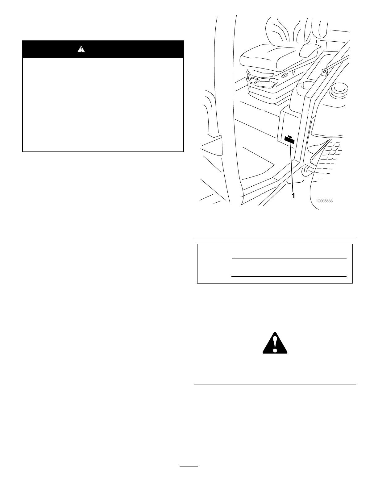
WARNING
CALIFORNIA
Proposition65Warning
Thisproductcontainsachemical
orchemicalsknowntotheStateof
Californiatocausecancer,birthdefects,
orreproductiveharm.
Dieselengineexhaustandsomeofits
constituentsareknowntotheStateof
Californiatocausecancer,birthdefects,
andotherreproductiveharm.
ItisaviolationofCaliforniaPublicResourceCode
Section4442or4443touseoroperatetheengineon
anyforest-covered,brush-covered,orgrass-covered
landunlesstheengineisequippedwithaspark
arrester,asdenedinSection4442,maintainedin
effectiveworkingorderortheengineisconstructed,
equipped,andmaintainedforthepreventionofre.
g008833
Figure1
Introduction
Thismachineisaride-on,rotary-bladelawnmower
intendedtobeusedbyprofessionaloperatorsin
commercialapplications.Itisdesignedprimarilyfor
mowinggrassonwell-maintainedlawnsinparks,
golfcourses,sportselds,alongroadways,andon
commercialgrounds.Itisnotdesignedformowing
brushorforagriculturaluses.
Readthisinformationcarefullytolearnhowtooperate
andmaintainyourproductproperlyandtoavoid
injuryandproductdamage.Youareresponsiblefor
operatingtheproductproperlyandsafely .
YoumaycontactTorodirectlyatwww.Toro.com
forproductsafetyandoperationtrainingmaterials,
accessoryinformation,helpndingadealer,orto
registeryourproduct.
Wheneveryouneedservice,genuineToroparts,or
additionalinformation,contactanAuthorizedService
DealerorToroCustomerServiceandhavethemodel
andserialnumbersofyourproductready.Figure1
identiesthelocationofthemodelandserialnumbers
ontheproduct.Writethenumbersinthespace
provided.
1.Modelandserialnumberlocation
ModelNo.
SerialNo.
Thismanualidentiespotentialhazardsandhas
safetymessagesidentiedbythesafety-alertsymbol
(Figure2),whichsignalsahazardthatmaycause
seriousinjuryordeathifyoudonotfollowthe
recommendedprecautions.
g000502
Figure2
1.Safety-alertsymbol
Thismanualuses2wordstohighlightinformation.
Importantcallsattentiontospecialmechanical
informationandNoteemphasizesgeneralinformation
worthyofspecialattention.
©2017—TheToro®Company
8111LyndaleAvenueSouth
Bloomington,MN55420
Contactusatwww.Toro.com.
2
PrintedintheUSA
AllRightsReserved

Contents
Safety.......................................................................4
GeneralSafety...................................................4
SoundPowerLevel............................................4
SoundPressureLevel........................................5
VibrationLevel....................................................5
Engine-EmissionCertication.............................5
SafetyandInstructionalDecals..........................6
Setup......................................................................17
1RemovingtheWing-Deck-ShippingStraps
andBraces....................................................17
2LoweringtheFront-DeckWinglets.................17
3CheckingtheTireandCasterWheel
Pressure.......................................................19
4LevelingtheFront,CenterDeck.....................19
5LevelingtheWingletDeckstotheFront,
CenterDeck..................................................19
6CheckingtheFluidLevels..............................20
7GreasingtheMachine....................................20
ProductOverview...................................................21
Controls...........................................................22
CabControls.................................................23
InfoCenterControl.........................................24
Specications..................................................34
Attachments/Accessories.................................34
BeforeOperation.................................................35
BeforeOperationSafety...................................35
CheckingtheEngine-OilLevel..........................36
CheckingtheCoolingSystems.........................36
CheckingtheHydraulicSystem........................36
FillingtheFuelTank..........................................36
CheckingtheTirePressure...............................37
CheckingtheCasterWheelTire
Pressure.......................................................37
CheckingtheT orqueoftheWheel-Lug
Nuts..............................................................38
AdjustingtheHeightofCut...............................38
AdjustingtheSkids...........................................40
AdjustingtheMowerDeckAnti-Scalp
Rollers...........................................................41
CheckingaMismatchBetweenMower
Decks............................................................42
AdjustingtheMirrors.........................................44
AimingtheHeadlights.......................................44
CheckingtheSafety-InterlockSwitches............44
CheckingtheBladeStoppingTime...................45
DuringOperation.................................................45
DuringOperationSafety...................................45
StartingandStoppingtheEngine......................46
RaisingorLoweringtheDecks..........................47
CuttingGrasswiththeMachine........................47
DieselParticulateFilterRegeneration...............48
UnderstandingtheOperatingCharacteristics
oftheMachine..............................................56
Understandingthe12Vand24VElectrical
Systems........................................................56
AutomaticReversing-FanCycle.......................56
OperatingTips.................................................57
AfterOperation....................................................58
AfterOperationSafety......................................58
PushingorT owingtheMachine........................58
IdentifyingtheTie-DownPoints........................59
HaulingtheMachine.........................................59
Maintenance...........................................................60
RecommendedMaintenanceSchedule(s)...........60
DailyMaintenanceChecklist.............................61
Service-IntervalChart.......................................63
Pre-MaintenanceProcedures..............................64
Pre-MaintenanceSafety...................................64
UsingtheBattery-DisconnectSwitch................64
RaisingtheMachine.........................................65
RemovingandInstallingthe
Inner-Wing-DeckCovers...............................65
Lubrication..........................................................66
GreasingtheBearingsandBushings................66
EngineMaintenance...........................................69
EngineSafety...................................................69
ServicingtheAirCleaner..................................69
ServicingtheEngineOil....................................71
AdjustingtheEngine-ValveClearance..............73
CleaningtheEngineEGRCooler......................73
InspectingtheEngineCrankcase-Breather
System..........................................................73
CheckingandReplacingFuelHosesand
Engine-CoolantHoses..................................73
LappingorAdjustingtheEngineIntakeand
ExhaustValves.............................................73
InspectingandCleaning
Engine-Emission-ControlComponents
andTurbocharger.........................................74
ServicingtheDiesel-OxidationCatalyst
(DOC)andtheSootFilter..............................74
FuelSystemMaintenance...................................75
ServicingtheFuelSystem................................75
ServicingtheWaterSeparator.........................75
ReplacingtheFuelFilterElement.....................76
ElectricalSystemMaintenance...........................76
ElectricalSystemSafety...................................76
LocatingtheFuses...........................................76
CheckingtheConditionoftheBatteries.............78
ChargingtheBatteries......................................78
Jump-StartingtheMachine...............................79
DriveSystemMaintenance..................................80
CalibratingtheTractionPedal...........................80
AdjustingtheTraction-PedalAngle...................80
CheckingtheRearWheelToe-In......................80
CoolingSystemMaintenance..............................81
CoolingSystemSafety.....................................81
CheckingtheEngine-CoolingSystem...............81
CleaningtheCoolingSystems..........................82
ChangingtheEngine-Cooling-System
Fluid..............................................................83
BeltMaintenance................................................84
Servicingthe12VAlternatorBelt......................84
3

Servicingthe24VAlternatorBeltandAC
CompressorBelt...........................................84
ReplacingtheBlade-DriveBelts.......................84
HydraulicSystemMaintenance...........................86
HydraulicSystemSafety...................................86
CheckingtheHydraulicFluid............................86
ChangingtheHydraulicFluidand
Filters............................................................87
CheckingtheHydraulicLinesand
Hoses............................................................88
InspectingtheHydraulicSystemT est
Ports.............................................................88
MowerMaintenance.............................................89
Pivoting(Tilting)theFrontMowerDeck
Upright..........................................................89
Pivoting(Tilting)theFrontMowerDeck
Down.............................................................90
AdjustingtheMower-DeckPitch.......................90
ServicingtheCaster-ArmBushings..................91
ServicingtheCasterWheelsand
Bearings........................................................91
BladeMaintenance..............................................92
BladeSafety.....................................................92
CheckingforaBentBlade................................92
RemovingandInstallingaBlade.......................92
InspectingandSharpeningaBlade...................93
CorrectingaMower-DeckMismatch.................93
CabMaintenance.................................................94
CleaningtheCab..............................................94
CleaningtheCabAirFilters..............................94
CleaningtheAir-Conditioning-Condenser
Coil...............................................................95
Storage...................................................................95
PreparingtheMachineforStorage...................95
Safety
Thismachinehasbeendesignedinaccordancewith
ENISO5395:2013andANSIB71.4-2012.
GeneralSafety
Thisproductiscapableofamputatinghandsand
feetandofthrowingobjects.Alwaysfollowallsafety
instructionstoavoidseriouspersonalinjury.
Usingthisproductforpurposesotherthanitsintended
usecouldprovedangeroustoyouandbystanders.
•Readandunderstandthecontentsofthis
Operator’sManualbeforeyoustarttheengine.
Ensurethateveryoneusingthisproductknows
howtouseitandunderstandsthewarnings.
•Donotputyourhandsorfeetnearmoving
componentsofthemachine.
•Donotoperatethemachinewithoutallguards
andothersafetyprotectivedevicesinplaceand
workingonthemachine.
•Keepclearofanydischargeopening.Keep
bystandersasafedistancefromthemachine.
•Keepchildrenoutoftheoperatingarea.Never
allowchildrentooperatethemachine.
•Stopthemachineandshutofftheenginebefore
servicing,fueling,oruncloggingthemachine.
Improperlyusingormaintainingthismachinecan
resultininjury.Toreducethepotentialforinjury,
complywiththesesafetyinstructionsandalwayspay
attentiontothesafety-alertsymbol,whichmeans
Caution,Warning,orDanger—personalsafety
instruction.Failuretocomplywiththeseinstructions
mayresultinpersonalinjuryordeath.
Youcanndadditionalitemsofsafetyinformationin
theirrespectivesectionsthroughoutthismanual.
SoundPowerLevel
Model31698
Thisunithasaguaranteedsoundpowerlevelof105
dBA,whichincludesanUncertaintyValue(K)of1.0
dBA.
Soundpowerlevelwasdeterminedaccordingtothe
proceduresoutlinedinISO11094.
Model31699
Thisunithasaguaranteedsoundpowerlevelof105
dBA,whichincludesanUncertaintyValue(K)of1.0
dBA.
4

Soundpowerlevelwasdeterminedaccordingtothe
proceduresoutlinedinISO11094.
SoundPressureLevel
Model31698
Thisunithasasoundpressurelevelattheoperator’s
earof90dBA,whichincludesanUncertaintyV alue
(K)of1.0dBA.
VibrationLevel
Hand-Arm
Model31698
Measuredvibrationlevelforrighthand=0.8m/s
Measuredvibrationlevelforlefthand=1.0m/s
UncertaintyValue(K)=0.5m/s
2
2
2
Soundpressurelevelwasdeterminedaccordingto
theproceduresoutlinedinENISO5395:2013.
Model31699
Thisunithasasoundpressurelevelattheoperator’s
earof82dBA,whichincludesanUncertaintyV alue
(K)of1.0dBA.
Soundpressurelevelwasdeterminedaccordingto
theproceduresoutlinedinENISO5395:2013.
CAUTION
Long-termexposuretonoisewhileoperating
themachinemaycausesomehearingloss.
Wearadequatehearingprotectionwhenever
youoperatethemachineforanextended
periodoftime.
Measuredvaluesweredeterminedaccordingtothe
proceduresoutlinedinENISO5395:2013.
Model31699
Measuredvibrationlevelforrighthand=0.8m/s
Measuredvibrationlevelforlefthand=1.0m/s
UncertaintyValue(K)=0.5m/s
Measuredvaluesweredeterminedaccordingtothe
proceduresoutlinedinENISO5395:2013.
2
WholeBody
Model31698
Measuredvibrationlevel=0.35m/s
UncertaintyValue(K)=0.18m/s
Measuredvaluesweredeterminedaccordingtothe
proceduresoutlinedinENISO5395:2013.
2
2
2
2
Model31699
Measuredvibrationlevel=0.35m/s
UncertaintyValue(K)=0.18m/s
Measuredvaluesweredeterminedaccordingtothe
proceduresoutlinedinENISO5395:2013.
2
2
Engine-Emission
Certication
TheengineinthismachineisEP ATier4FinalandEU
Stage3bemissionscompliant.
5
SafetyandInstructionalDecals
Safetydecalsandinstructionsareeasilyvisibletotheoperatorandarelocatednearanyarea
ofpotentialdanger.Replaceanydecalthatisdamagedorlost.
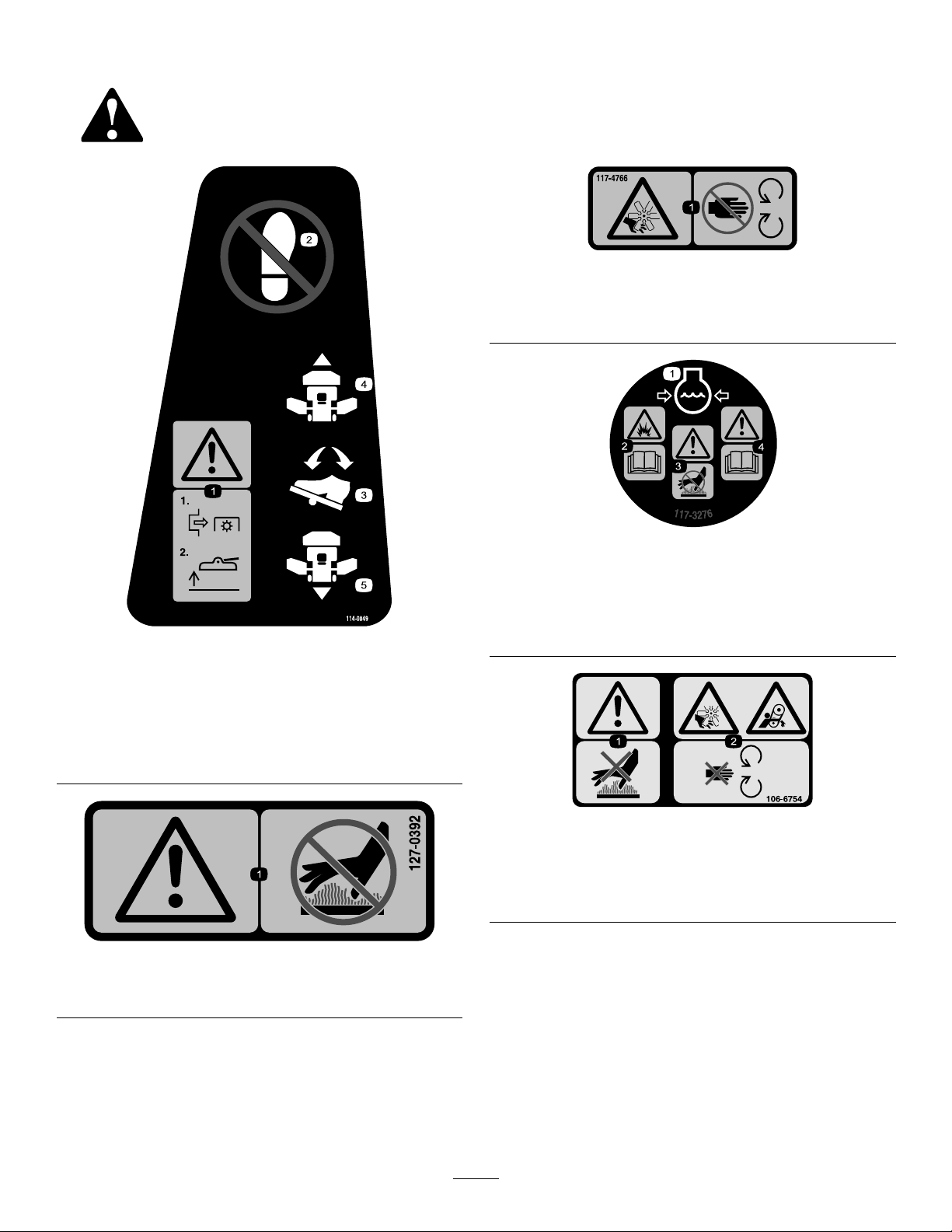
decal117-4766
117-4766
1.Cutting/dismembermenthazard,fan—stayawayfrom
movingparts;keepallguardsandshieldsinplace.
114-0849
1.Warning—disengagethePTOthenraisethedeck.
2.Nostep
3.Traction-controlpedal
4.Forward
5.Reverse
127-0392
decal117-3276
117-3276
1.Enginecoolantunder
pressure
2.Explosionhazard—read
decal114-0849
theOperator'sManual.
3.Warning—donottouchthe
hotsurface.
4.Warning—readthe
Operator'sManual.
decal106-6754
106-6754
1.Warning—donottouchthehotsurface.
2.Cutting/dismembermenthazard,fanandentanglement
hazard,belt—stayawayfrommovingparts.
decal127-0392
1.Warning—keepawayfromhotsurfaces.
6
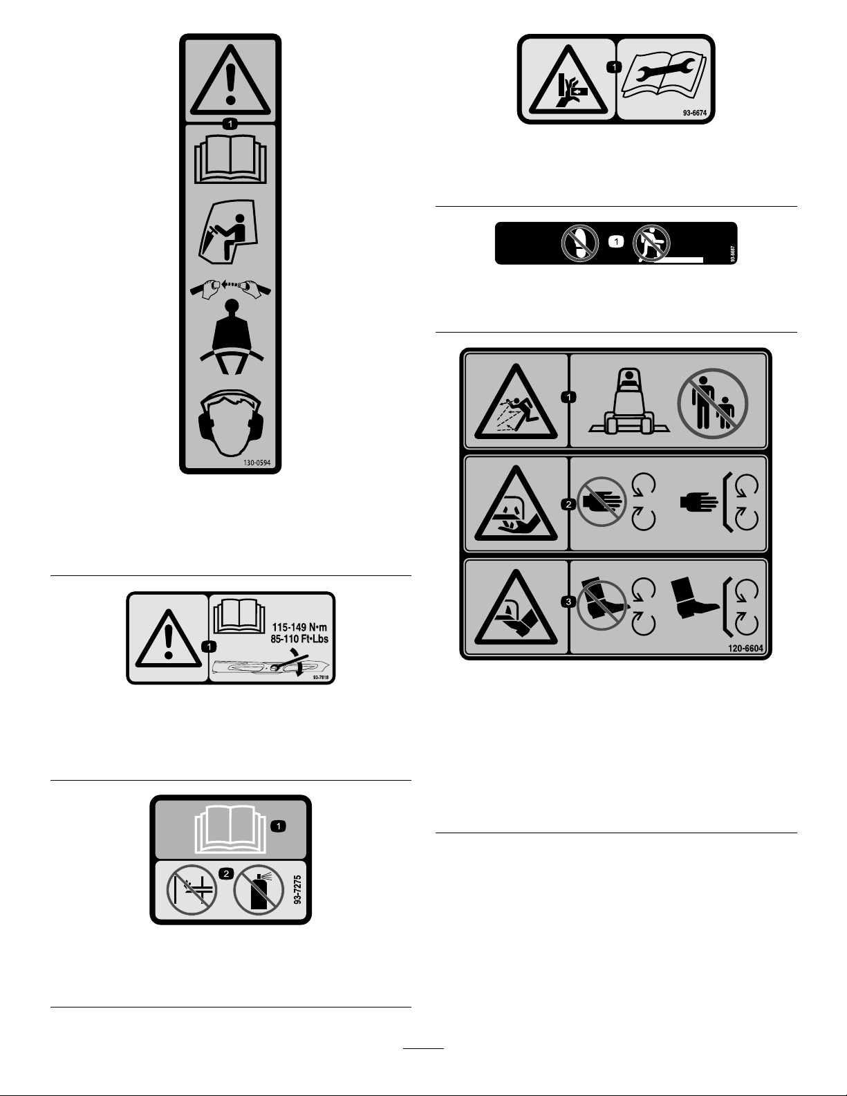
130-0594
ModelwithCabOnly
decal93-6674
93-6674
1.Crushinghazard,hand—readtheinstructionsbefore
servicingorperformingmaintenance.
decal93-6687
93-6687
1.Donotstephere.
decal130-0594
1.Warning—readtheOperator’sManual;whensittinginthe
cab,alwayswearaseatbelt;wearhearingprotection.
93-7818
1.Warning—readtheOperator'sManualforinstructionson
torquingthebladebolt/nutto1 15to149N·m(85to1 10
ft-lb).
93-7275
decal120-6604
decal93-7818
120-6604
1.Thrownobjecthazard—keepbystandersawayfromthe
machine.
2.Cutting/dismembermenthazardofhand,mower
blade—stayawayfrommovingparts;keepallguardsand
shieldsinplace.
3.Cutting/dismembermenthazardoffoot,mowerblade—stay
awayfrommovingparts;keepallguardsandshieldsin
place.
decal93-7275
1.ReadtheOperator’sManual—donotusestartinguidto
starttheengine.
7
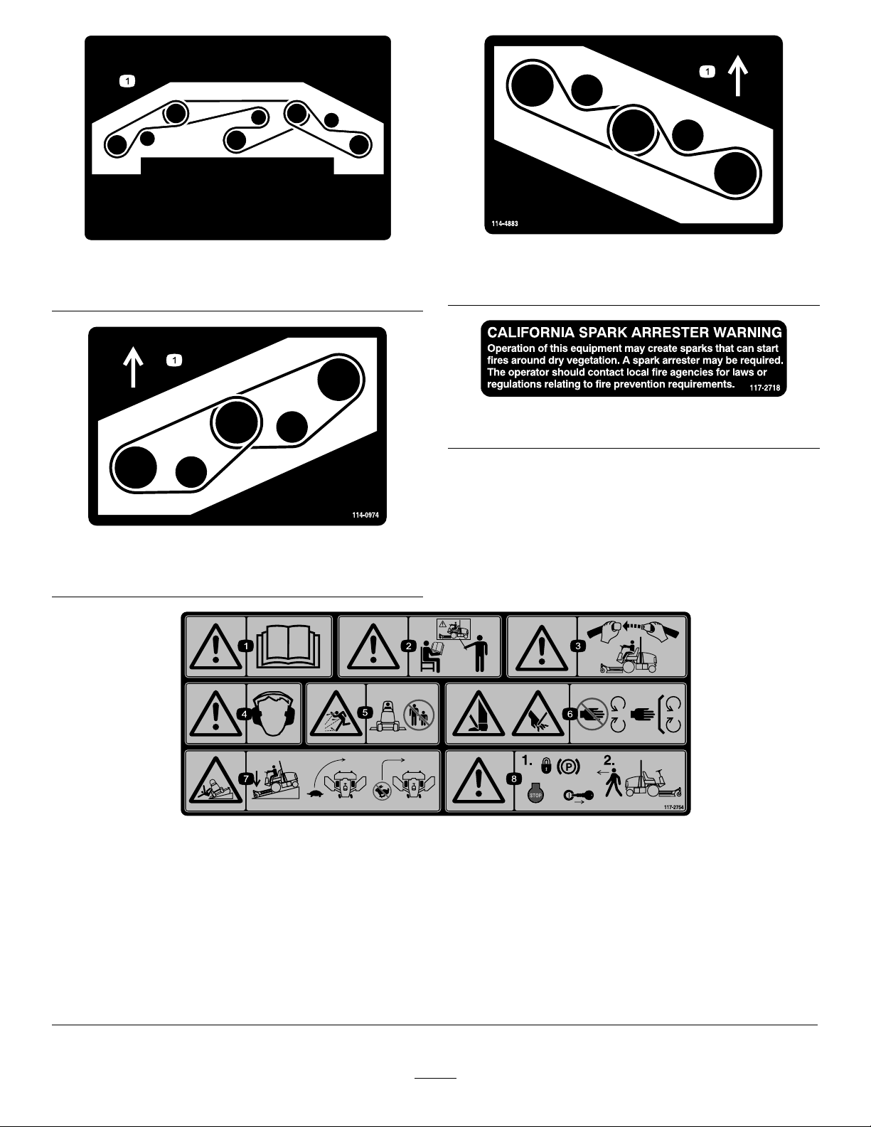
114-0922
decal114-0922
114-0922
1.Beltrouting
1.Beltrouting
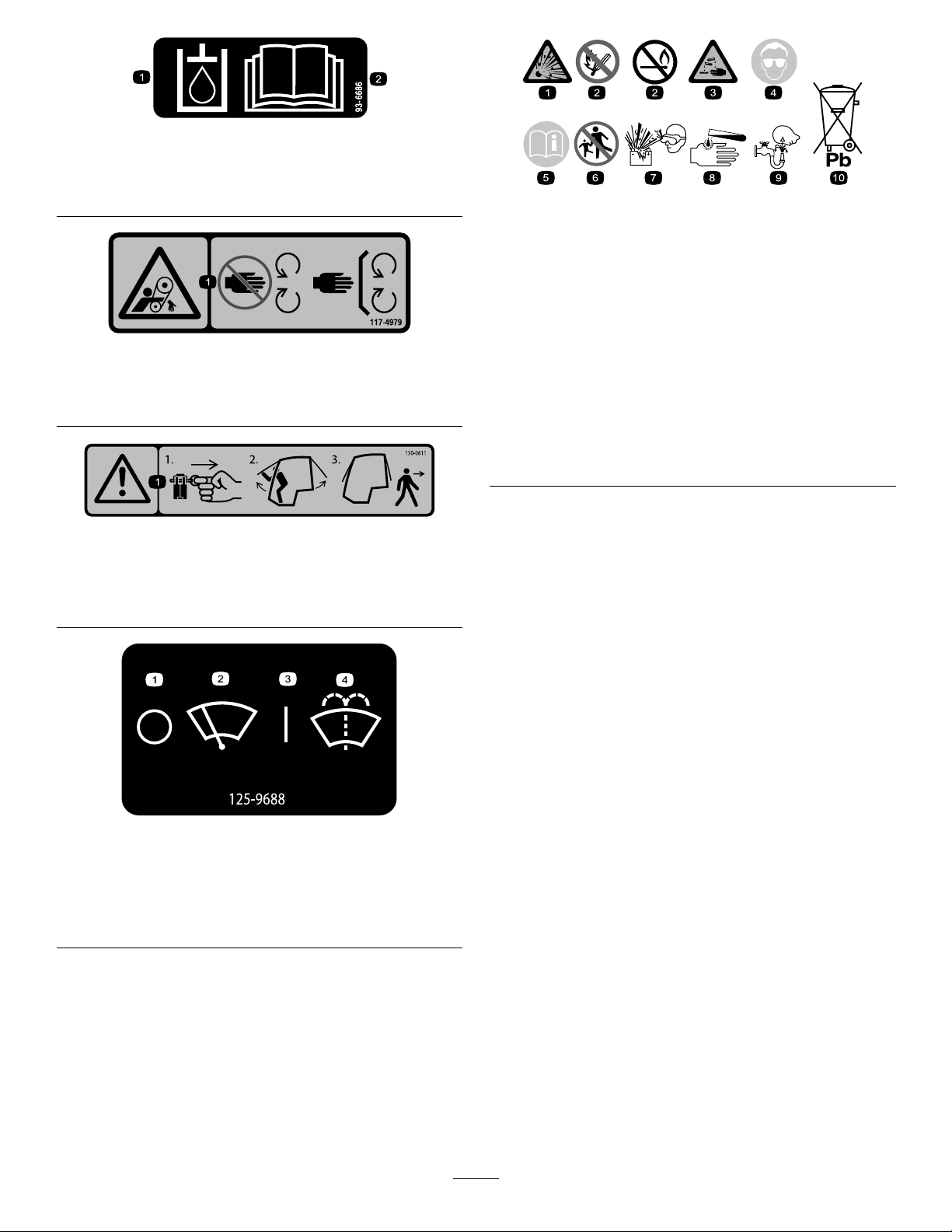
114-4883
decal114-4883
decal117-2718
117-2718
decal114-0974
114-0974
1.Beltrouting
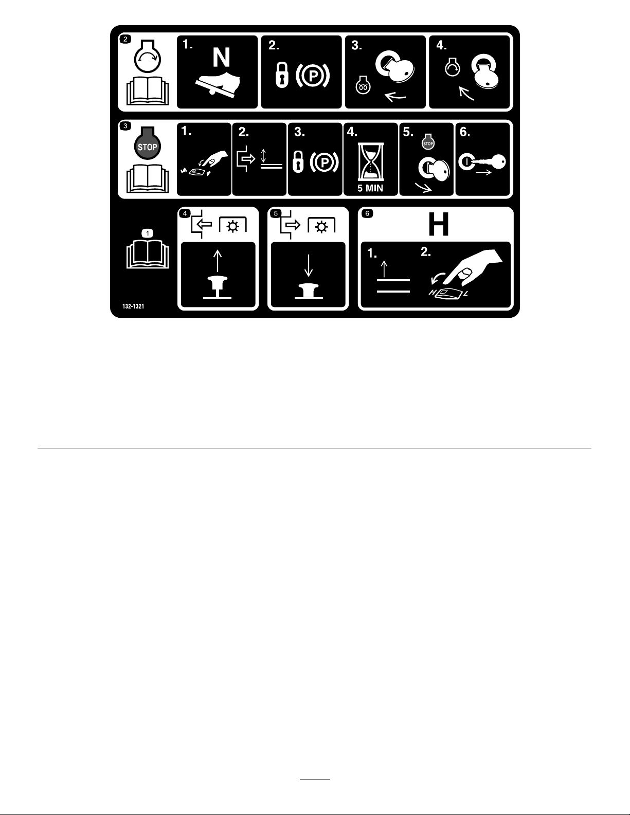
117-2754
1.Warning—readtheOperator'sManual.
2.Warning—donotoperatethismachineunlessyouaretrained.
3.Warning—weartheseatbeltwhenseatedintheoperator'sposition.
4.Warning—wearhearingprotection.
5.Thrownobjecthazard—keepbystandersasafedistancefromthemachine.
6.Cuttinghazardofhandorfoot—stayawayfrommovingparts;keepallguardsinplace.
7.Tippinghazard—lowerthecuttingunitwhendrivingdownslopes;slowmachinebeforeturning;donotturnathighspeeds
8.Warning—settheparkingbrake,stoptheengine,andremovetheignitionkeybeforeleavingthemachine.
8
decal117-2754
1.Hydraulicoil
2.ReadtheOperator'sManual.
decal93-6686
93-6686
decalbatterysymbols
BatterySymbols
Someorallofthesesymbolsareonyourbattery .
117-4979
1.Entanglementhazard,belt—stayawayfrommovingparts;
keepallguardsandshieldsinplace.
130-0611
ModelwithCabOnly
1.Warning—1)Removethepin;2)Raisethedoors;3)Exit
thecab
decal117-4979
decal130-0611
1.Explosionhazard
2.Nore,opename,or
6.Keepbystandersasafe
7.Weareyeprotection;
smoking
3.Causticliquid/chemical
8.Batteryacidcancause
burnhazard
4.Weareyeprotection.9.Flusheyesimmediately
5.ReadtheOperator's
10.Containslead;donot
Manual.
distancefromthebattery.
explosivegasescan
causeblindnessandother
injuries.
blindnessorsevereburns.
withwaterandgetmedical
helpfast.
discard.
ModelwithCabOnly
1.Windshieldwipers—off
2.Windshieldwipers
decal125-9688
125-9688
3.Windshieldwipers—on
4.Spraywindshieldwasher
uid
9
132-1321
1.ReadtheOperator’sManual.4.ToengagethePTO,pulluptheknob.
2.Tostarttheengine:1)Putthetractionpedalinneutral;2)Set
theparkingbrake;3)Turnthekeytotherunposition;4)Turn
thekeytotheenginestartposition.
3.Toshutofftheengine:1)Movethethrottleswitchtoslow;
2)DisengagethePTO;3)Settheparkingbrake;4)Wait5
minutes;5)TurntheignitionkeytoStop;and6)Removethe
key.
5.TodisengagethePTO,pushdowntheknob.
6.Toswitchthetransmissiontohighspeed,fullyraisethe
attachmentsandswitchthespeedcontroltotheHIGHposition.
decal132-1321
10
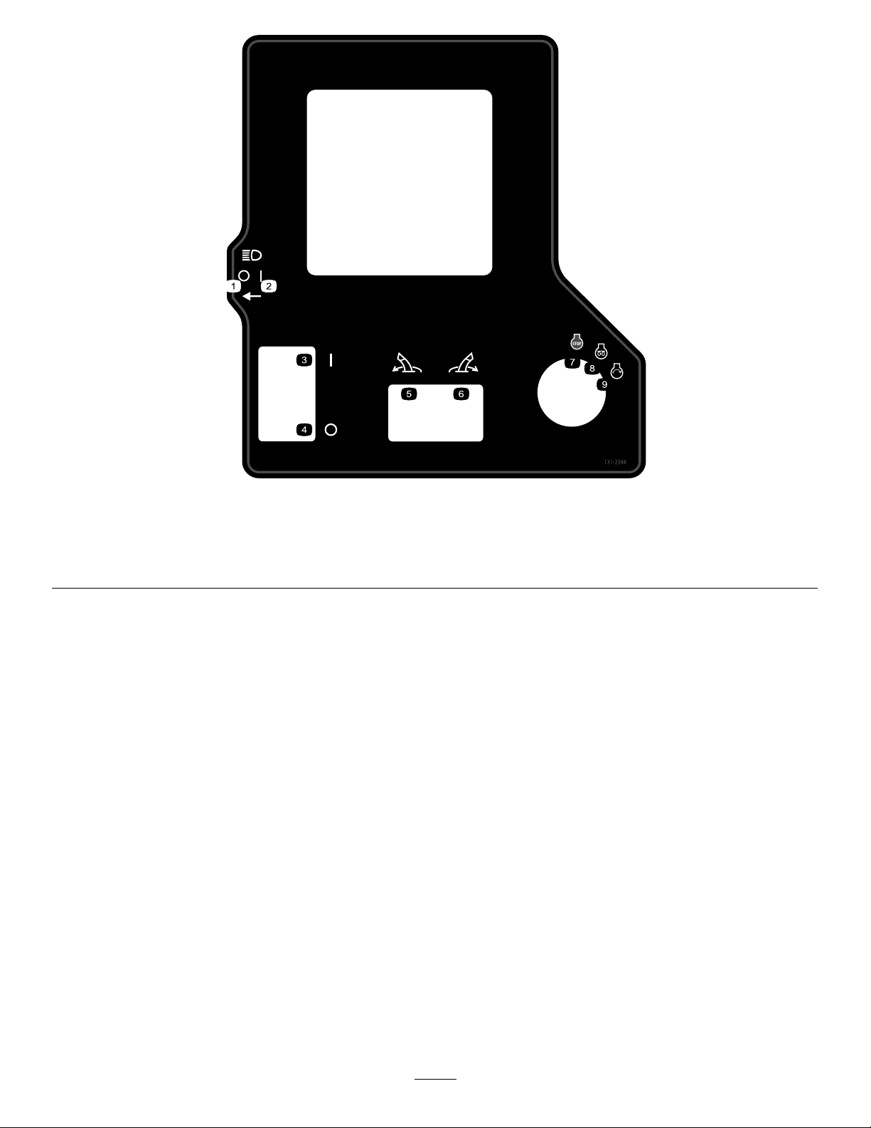
decal131-2348
131-2348
1.Headlights—off4.Parkingbrake—off
2.Headlights—on
5.Pivottheattachmentleft.
3.Parkingbrake—on6.Pivottheattachmentright.9.Engine—start
7.Engine—stop
8.Engine—run,electricpreheat
11
132-3600
ModelwithCabOnly
decal132-3600
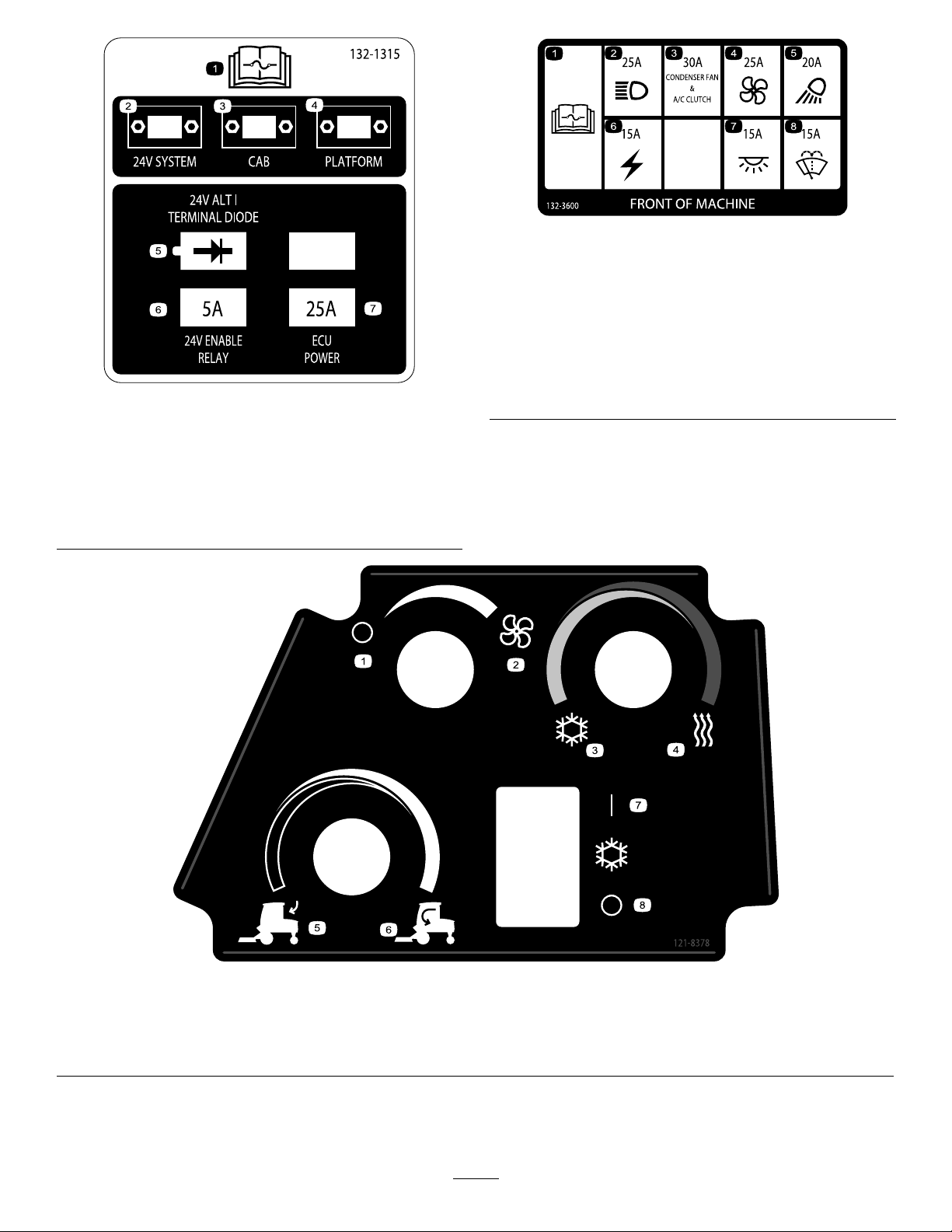
132-1315
1.ReadtheOperator's
Manualformore
informationonfuses.
2.24Vsystem6.24Venablerelay—5A
3.Cab7.ECUpower—25A
4.Platform
5.24Valt/terminaldiode
1.ReadtheOperator's
5.Workinglight—20A
Manualformore
informationonfuses.
2.Headlight—25A6.Auxiliarypower—15A
3.CondenserfanandA/C
7.Cablight—15A
clutch—30A
decal132-1315
4.Fan—25A8.Windshieldwipers—15A
1.Fan—off3.Coldair
2.Fan—onfull
4.Hotair6.Internalair
decal121-8378
121-8378
ModelwithCabOnly
5.Externalair7.Airconditioner—on
8.Airconditioner—off
12
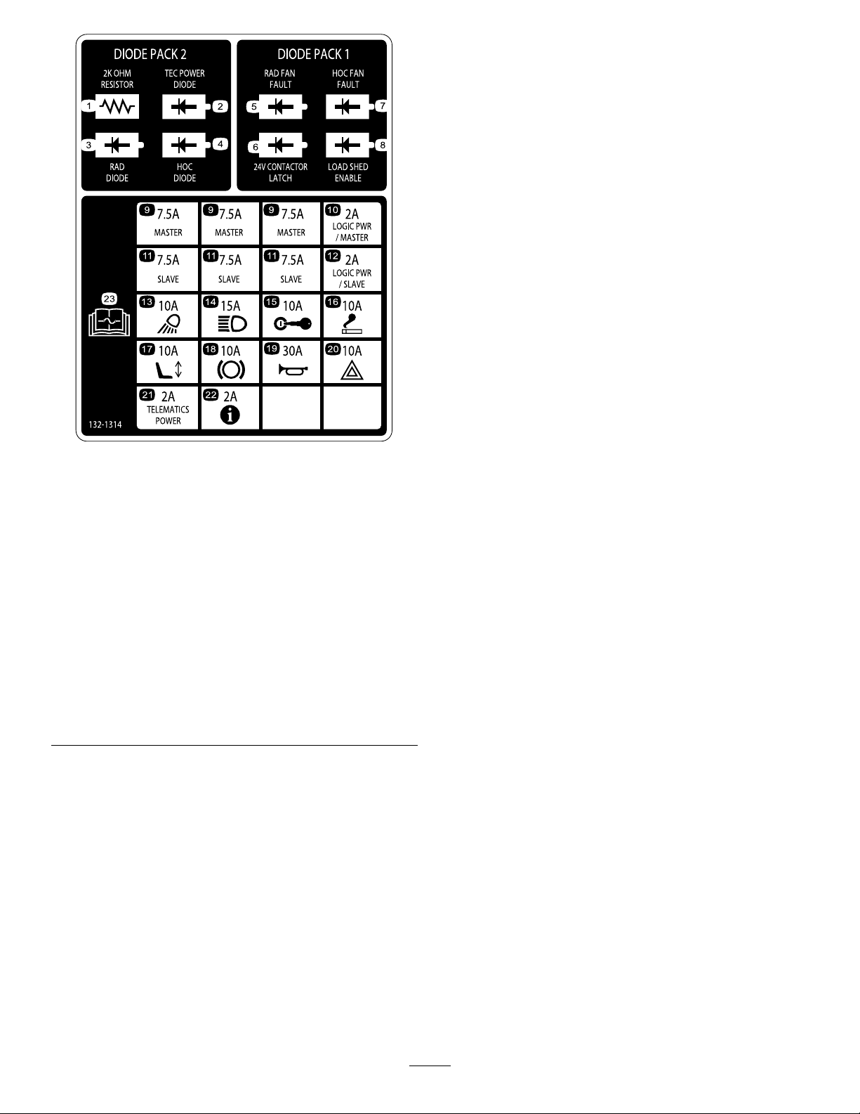
decal132-1314
132-1314
1.Resistor(2kOhm)
2.TECpowerdiode
13.Workinglight—10A
14.Headlight—15A
3.RADdiode15.Ignition—10A
4.HOCdiode16.Cigarettelighter—10A
5.RADfanfault
17.Electricseat—10A
6.Contactorlatch(24V)18.PTO—10A
7.HOCfanfault
19.Horn—30A
8.Loadshedenable20.Hazardlight—10A
9.Master—7.5A21.Telematicspower—2A
10.Logicpower/master—2A22.Infocenter—2A
11.Slave—7.5A23.Formoreinformationon
fuses,readtheOperator’s
Manual.
12.Logicpower/slave—2A
13
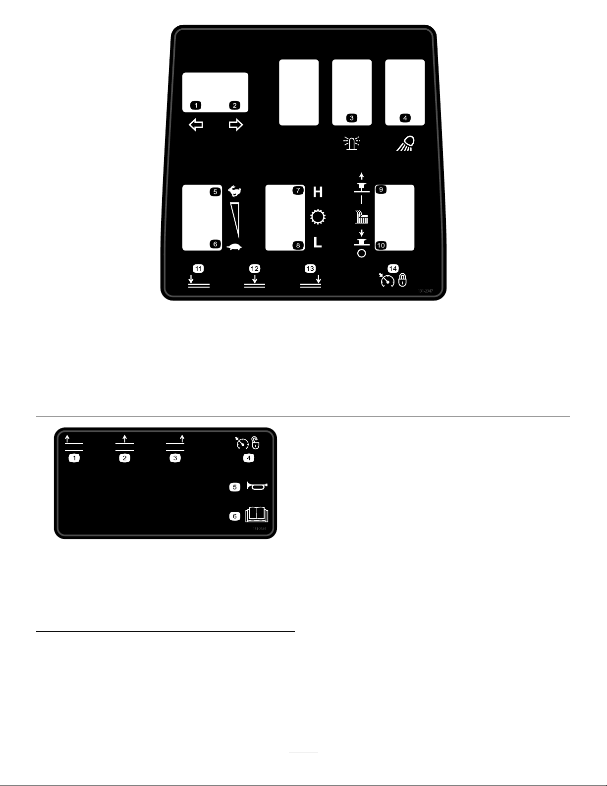
decal131-2347
131-2347
1.Left-turnsignal5.Enginespeed—fast
9.Pulluptoturnonthecutting
unit.
2.Right-turnsignal6.Enginespeed—slow
10.Pushdowntoturnoffthe
cuttingunit.
3.Beacon7.Transmission—highrange
11.Lowertheleftcuttingunit.
4.Worklight8.Transmission—lowrange12.Lowerthecentercutting
unit.
decal131-2349
131-2349
1.Raisetheleftcuttingunit.4.Cruisecontrol—off
2.Raisethecentercutting
unit.
3.Raisetherightcuttingunit.
5.Horn
6.ReadtheOperator's
Manual.
13.Lowertherightcuttingunit.
14.Cruisecontrol—set
14
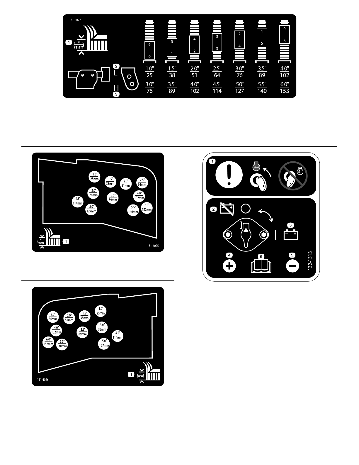
decal131-6027
131-6027
1.Height-of-cutsettings3.Lowercasterposition—heightsofcut76to153cm(3to6
inches)
2.Uppercasterposition—heightsofcut25to102cm(1to4
inches)
decal131-6025
131-6025
1.Heightofcut
132-1313
decal132-1313
1.Heightofcut
1.Attention—movethe
4.Positiveterminal
keytotheenginestop
positionbeforeservicing
thebattery;donotservice
thebatterywiththeengine
running.
2.Battery—disconnect5.Negativeterminal
3.Battery—connect
6.ReadtheOperator’s
Manualformore
informationonservicing
thebattery.
decal131-6026
131-6026
15
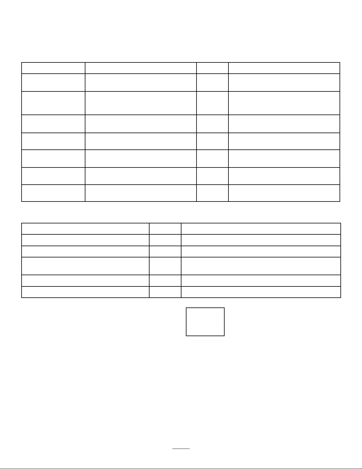
decal132-1316
132-1316
1.Entanglementhazard,belt—keepawayfrommovingparts.
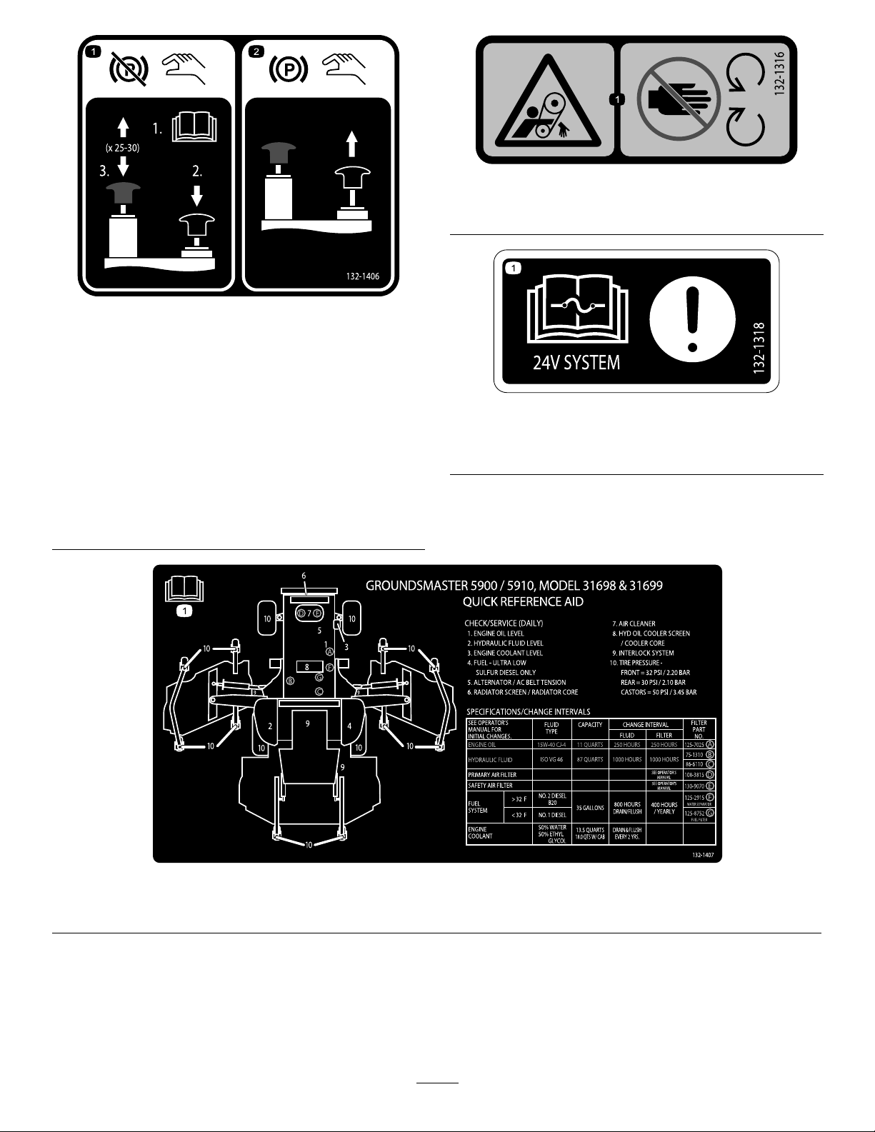
decal132-1406
132-1406
1.Releasingtheparking
brakewhentheengine
isoff—1)Openthetow
valvesonthetraction
pump(readtheOperator's
Manual);2)Pushdown
andholdtheblackknobto
releasetheparkingbrake;
3)Workthehandpump
upanddown.Youcan
releasetheblackknob
after2to3pumps.The
parkingbrakewillrelease
after25to30pumps.
2.Engagingtheparking
brake—pulluponthe
blackknob;themanual
valveresetswhenyou
starttheengine.
decal132-1318
132-1318
1.Attention—readtheOperator'sManualforinformationon
fuses.
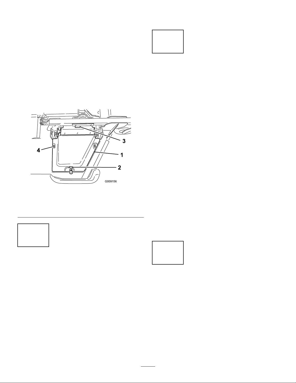
1.ReadtheOperator'sManualformoreinformationonservicingthemachine.
decal132-1407
132-1407
16
Setup
LooseParts
Usethechartbelowtoverifythatallpartshavebeenshipped.
ProcedureDescription
1
2
3
4
5
6
7
MediaandAdditionalParts
Description
Nopartsrequired
Rightdeckcover1
Leftdeckcover
V-belt2
Nopartsrequired
Nopartsrequired
Nopartsrequired
Nopartsrequired
Nopartsrequired
Qty.
Qty.
Use
–
1
–
–
–
–
–
Removethewing-deck-shippingstraps
andbraces.
Lowerthefront-deckwinglets.
Checkthetireandcasterwheel
pressure.
Levelthefront,centerdeck.
Levelthewingletdeckstothefront,
centerdeck.
Checktheuidlevels.
Greasethemachine.
Use
Operator'sManual
Engineowner'smanual1
PartsCatalog
Operatortrainingmaterials
Declarationofconformity
Note:Determinetheleftandrightsidesofthe
machinefromthenormaloperatingposition.
1
1
1
1
Reviewitbeforeoperatingthemachine.
Useittoreferenceengineinformation.
Useittoreferencepartnumbersandorderreplacement
parts.
Readthematerialsbeforeoperatingthemachine.
ForCEcompliance
1
Removingthe Wing-Deck-ShippingStraps andBraces
NoPartsRequired
Procedure
Removethestrapsandbracessecuringthewing
decksforshipping.
17
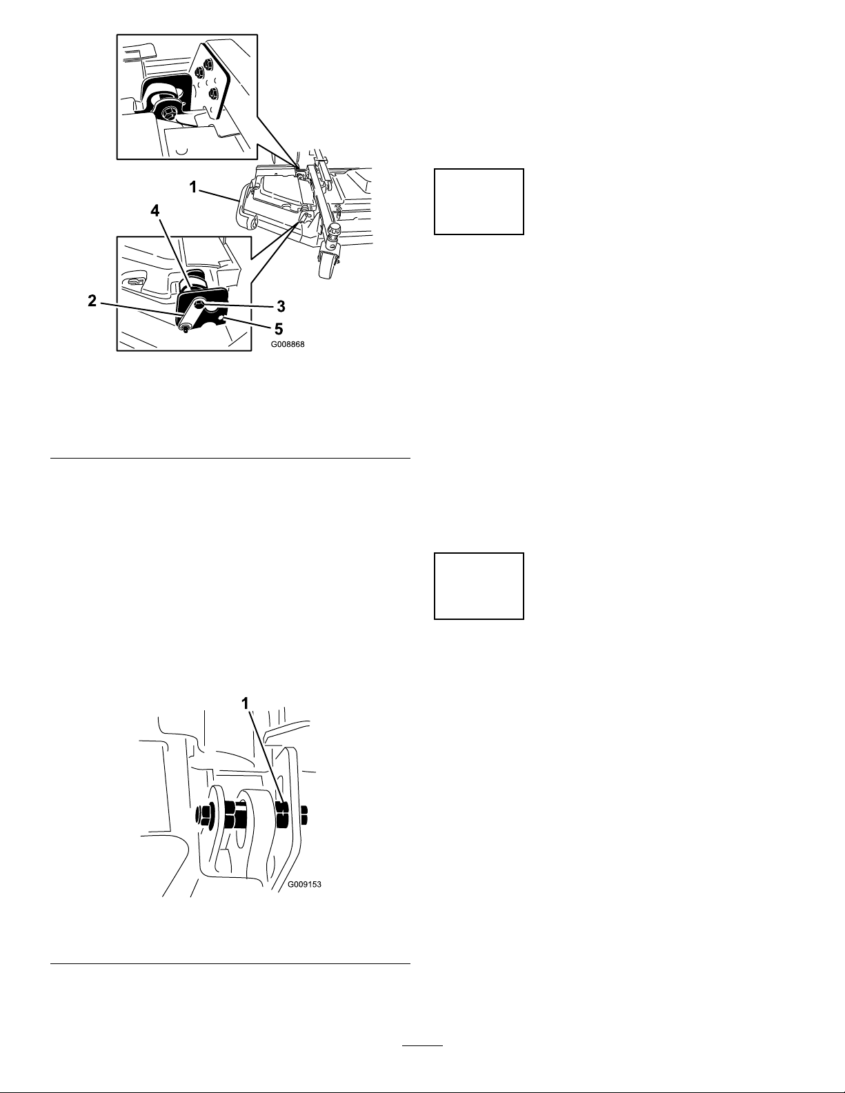
2
LoweringtheFront-Deck
Winglets
Partsneededforthisprocedure:
1Rightdeckcover
1
Leftdeckcover
2V-belt
Procedure
1.Removethenutssecuringthefrontandrearstop
boltstotherightwinglet-deckmounts(Figure3).
Note:Ensurethatthestopboltengagesthetab
onthehingepin.
g008868
Figure4
1.Winglet4.Eccentric
2.Hingepin5.Lowerhole
3.Bolt
Figure3
1.Winglet4.Eccentric
2.Hingepin5.Upperhole
3.Stopbolt
2.Whilesupportingtherightwinglet,removethe
frontandrearstopboltsfromthedeckmounts
(Figure3).
6.Deckmounts
Note:Leavetheeccentricspositionedbetween
thedeckmounts.
3.Lowerthewinglettotheoperatingposition.
4.Installthefrontandrearstopboltsthroughthe
upper-mountingholesandeccentrics(Figure4).
5.Installthenutssecuringthestopbolts.
Note:Donottightenthenutsatthistime.
6.Repeatthisprocedureonleftwinglet.
7.Installthewingletbeltsasfollows:
A.Startthebeltaroundthewinglet-spindle
pulleyandthefront-deck-spindlepulley
(Figure5).
g009013
g009155
Figure5
1.Winglet-spindlepulley3.Idlerpulley
2.Front-deck-spindlepulley
18
B.Usingaratchetwrenchorasimilartool,
movetheidlerpulleyawayfromthepulleys
(Figure5).
C.Routethebeltaroundthewinglet-spindle
pulleyandtheupper-spindlepulleyonthe
frontdeck.
D.Releasetheidlerpulleytoputtensionon
thebelt.
8.Installthewinglet-deckcoverandsecureitwith
therubberlatch(Figure6).
Note:Ensurethatyouslidethecoverunderthe
front,centerdeck-covertabsbeforeinsertingit
ontothemountinghooksandpost.
9.Repeatthisprocedureontheotherwinglet.
tiresizebetweenthefrontandreartires.Onlyuse
genuineTorotires.
4
LevelingtheFront,Center Deck
NoPartsRequired
Procedure
Note:Performthisprocedureonaat,levelsurface.
RefertoAdjustingtheHeightofCut(page38).
1.Rotatethebladeoneachouterspindleuntilthe
endsfaceforwardandbackward.
2.Measurefromtheoortothefronttipofthe
blade.
Figure6
1.Cover
2.Rubberlatch4.Mounthooks
3.Front,centerdeck-cover
tabs
3
CheckingtheTireand CasterWheelPressure
NoPartsRequired
Procedure
Checkthetireandcasterwheelpressurebeforeuse;
refertoCheckingtheTirePressure(page37)and
CheckingtheCasterWheelTirePressure(page37).
Important:Maintainpressureinalltiresto
ensureagoodquality-of-cutandpropermachine
performance.Donotunderinatethetires.
Important:Tractionperformance,including
tire-slipcontrol,isdependentontheratioofthe
3.Adjustthe3mm(1/8inch)shimsonthefront
casterfork(s)tomatchthedesiredheightofcut.
4.Rotatetheblades180°andmeasurefromthe
g009156
oortotherear-facingtipoftheblade.
5.Loosenthelowerjamnutsontheheight-of-cut
chainU-bolt.
6.Adjustthenutstoraiseorlowertherearofthe
mowerdecksothatthetipsoftherearblades
are6.35mm(1/4inch)to9.53mm(3/8inch)
higherthanthefronttips.
7.Tightenthejamnuts.
5
LevelingtheWingletDecks totheFront,CenterDeck
NoPartsRequired
Procedure
1.Rotatethebladeoneachwingletsothatitpoints
sidetoside.
2.Loosentheboltsandnutssecuringthe2
eccentricspacerstothewinglets(Figure7).
19
6.Adjusttheforwardeccentricuntilitjustmakes
contactwiththeinnerslotsurfaceofthe
winglet-pivotbrackets.
7.Tightentheboltandnutforthiseccentricto149
N·m(1 10ft-lb).
8.Repeattheprocedureontheoppositewinglet.
6
CheckingtheFluidLevels
NoPartsRequired
Figure7
1.Winglet4.Eccentric
2.Hingepin5.Upperhole
3.Stopbolt
3.Rotatetheforwardeccentricuntilitreaches
maximumclearancewiththeinner-slotsurface
ofthewinglet-pivotbracket.
4.Rotatetherear(closesttothetractionunit)
eccentricuntiltheoutsidebladetipisabout3
mm(1/8inch)higherthanthedesiredheightof
cut(Figure7).
Note:Thereisanotchontheeccentrichex,
whichis180°fromthelobeontheeccentric
cam(Figure8).Usethenotchestoreference
thelocationofthelobeswhenadjustingthe
eccentrics.
g008868
Procedure
1.Checktheengine-oillevelbeforestartingthe
engine;refertoCheckingtheEngine-OilLevel
(page71).
2.Checkthehydraulic-uidlevelbeforestarting
theengine;refertoCheckingtheHydraulicFluid
(page86).
3.Checkthecoolingsystembeforestartingthe
engine;refertoCheckingtheEngine-Cooling
System(page81).
7
GreasingtheMachine
NoPartsRequired
Procedure
Figure8
1.Eccentricnotch
5.Tightentheboltandnutforthiseccentricto149
N·m(1 10ft-lb).
Greasethemachinebeforeuse;refertoLubrication
(page66).Failuretoproperlygreasethemachine
resultsinprematurefailureofcriticalparts.
g009153
20
ProductOverview
Figure9
1.Wingmowerdeck5.Fueltank
2.Controlpanel6.Steeringwheel
3.Rollover-ProtectionSystem(ROPS)
4.Hood
7.Frontmowerdeck
8.InfoCenter
21
g031657
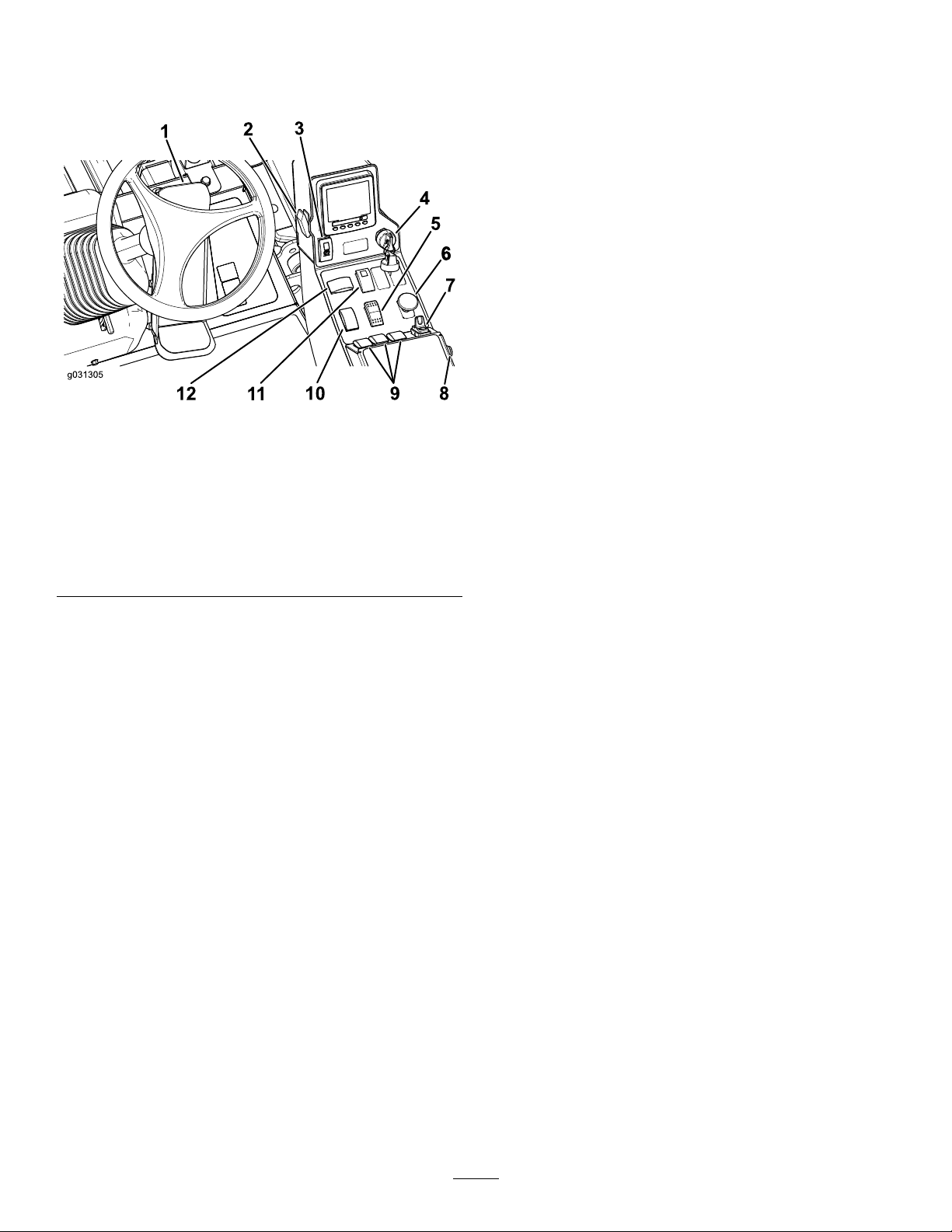
Controls
KeySwitch
Note:Determinetheleftandrightsidesofthe
machinefromthenormaloperatingposition.
Figure10
1.Tractionpedal
2.Lightswitch8.Hornbutton
3.Parking-brakeswitch
4.Keyswitch10.Throttleswitch
5.High—Lowrange-speed
switch
6.PTOswitch
7.Cruise-controlswitch
9.Deck-liftswitches
11.Hazardswitch
12.Turn-signalswitch
Thekeyswitchhas3positions:STOP,RUN/PREHEA T,
andSTART(Figure10).
High-LowRange-SpeedSwitch
PressthefrontoftheswitchtoselectHIGH-SPEED
RANGE.Presstherearoftheswitchtoselect
LOW-SPEEDRANGE.Themachinemustbestationary
ortravelingatlessthan1.0km/h(0.6mph)toshift
betweenHIGHandLOW(Figure10).
PTOSwitch
ThePTOswitchhas2positions:OUT(start)and
IN(stop).PulloutthePTObuttontoengagethe
implementormower-deckblades.Pushinthebutton
g031305
todisengagetheimplementoperation(Figure10).
Cruise-ControlSwitch
Thecruise-controlswitchsetsyourdesiredspeedof
themachine.
Movethecruise-controlswitchtothecenterposition
toturnthecruisecontroltotheONposition.Press
theswitchforwardtosetthespeed.Presstheswitch
rearwardtodisengagethecruisecontrol.(Figure10).
TractionPedal
Thetractionpedalcontrolstheforwardandreverse
operation.Pressthetopofthepedaltomovethe
machineforwardandthebottomtomoveitbackward.
Groundspeeddependsonhowfaryoupressthe
pedal.Formaximumgroundspeed,fullypressthe
pedalwhilethethrottleisintheHIGHIDLEposition
(Figure10).
Tostopthemachine,reduceyourfootpressureon
thetractionpedalandallowittoreturntothecenter
position.
LightSwitch
Pressthelightswitchupwardtoturnthelightstothe
ONposition(Figure10).
Pressthelightswitchdownwardtoturnthelightsto
theOFFposition.
Parking-BrakeSwitch
Theparking-brakeswitchrequires2actionstosetthe
brake.Whileholdingthesmalllatchback,pressthe
parking-brakeswitchforwardtoengagetheparking
brake.Presstheparking-brakeswitchrearwardto
disengagetheparkingbrake(Figure10).
Note:Footpedalmovementalsodisengagesthe
cruisecontrol.
Whenyouengagethecruisecontrol,youcan
changethecruise-controlspeed;refertoSettingthe
Cruise-ControlSpeed(page30).
HornButton
Pressthehornbuttontoactivatethehorn(Figure10).
Deck-LiftSwitches
Thedeck-liftswitchesraiseandlowerthemower
decks(Figure10).
Presstheswitchesforwardtolowerthemowerdeck
andrearwardtoraisethemowerdeck.
Note:Thedecksdonotlowerwhilethemachineis
intheHIGH-speedrange,andthedecksdonotraise
orlowerifyouareoutoftheseatwhiletheengineis
running.
Note:Thedeck-raisingfunctionislimitedatengine
speedsbelow2,000rpm.Only1deckraisesatatime
below2,000rpm.
22

ThrottleSwitch
Thethrottleswitchhas2positions:LOWIDLEandHIGH
IDLE(Figure10).
Presstheswitchforwardfor2ormoresecondstoset
thethrottleatHIGHIDLE;presstheswitchrearward
for2ormoresecondstosetthethrottleatLOWIDLE;
ormomentarilypresstheswitchineitherdirectionto
increaseordecreasetheenginespeedin100-rpm
increments.
HazardSwitch
Pressthehazardswitchforwardtoengagethehazard
lightsandrearwardtodisengagethehazardlights
(Figure10).
Turn-SignalSwitch
CabControls
Model31699Only
Presstheleftsideoftheturn-signalswitchtoactivate
theleft-turnsignalandtherightsideoftheswitchto
activatetheright-turnsignal(Figure10).
Note:Thecenterpositionisoff.
PowerPoint
Youcaninsertyourportablechargerintothepower
pointtochargeapersonaldevice,suchasaphoneor
otherelectronicdevice(Figure11).
Figure11
1.Powerpoint
g032672
Figure12
1.Air-conditioningswitch4.Temperaturecontrol
2.Air-recirculationcontrol5.Windshield-wiperswitch
3.Fancontrol
Air-RecirculationControl
Setsthecabtoeitherrecirculatetheairinthecabinor
todrawairintothecabinfromoutside(Figure12).
6.Blankswitchesforoptional
kits
•Setittorecirculatetheairwhenusingthe
air-conditioning.
•Setittodrawairinwhenusingtheheaterorfan.
FanControl
Rotatethefancontrolknobtoregulatethespeedof
thefan(Figure12).
g033266
TemperatureControl
Rotatethetemperaturecontrolknobtoregulatethe
airtemperatureinthecab(Figure12).
AudibleAlarm(Console)
Thealarmisactivatedwhenafaultisdetected.
Thebuzzersoundswhenthefollowingoccur:
•Whentheenginesendsastopfault
•Whentheenginesendsacheck-enginefault
•Whenthefuellevelislow
Windshield-WiperSwitch
Usethisswitchtoturnthewindshieldwipersonor
off(Figure12).
AirConditioningSwitch
Usethisswitchtoturntheairconditioningonoroff
(Figure12).
WindShieldLatch
Liftuponlatchestoopenthewindshield(Figure13).
Pressinonlatchtolockwindshieldinopenposition.
23
Pulloutanddownonlatchtocloseandsecurewind
11.3
1
2
3
4
5
6
8
9
G033320
7
shield.
Figure13
1.Windshieldlatch
RearWindowLatch
Liftuponlatchestoopentherearwindow.Pressin
onlatchtolockwindowinopenposition.Pulloutand
downonlatchtocloseandsecurewindow(Figure13).
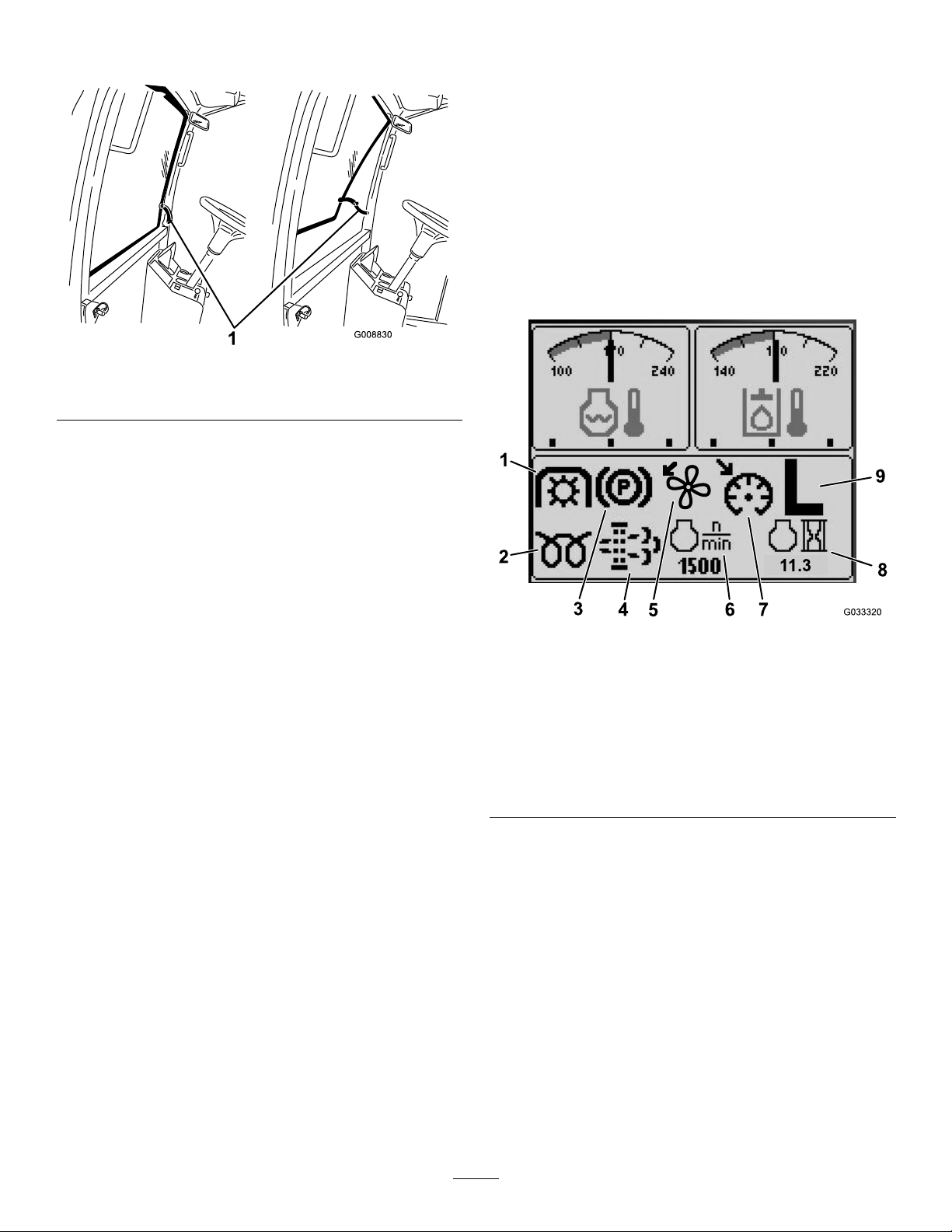
InfoCenterControl
Start-UpScreen
Whenyoustartthemachine,thestart-upscreen
appears,displayingthecorrespondingiconsthat
apply(i.e.,theparkingbrakeisapplied,thePTOisin
theONposition,cruisecontrolisintheONposition).
Note:Thefollowinggureisanexamplescreen;this
screenismeanttoshowallofthepotentialiconsthat
couldappearonthescreenwhileoperating.
Refertothefollowinggraphicforalloftheicon
meanings(Figure14).
g008830
Important:Therearwindowmustbeclosed
beforeopeningthehoodordamagemayoccur.
Seat-AdjustingLever
Pulloutthelevertoslidetheseatforwardorrearward.
Seat-Back-AdjustingLever
Movethelevertoadjusttheseat-backangle.
Armrest-AdjustingKnob
Rotatetheknobtoadjusttheangleofthearmrest.
Figure14
1.PTOindicator
2.Glow-plugindicator7.Cruise-control-set
3.Parking-brakeindicator8.Engine-hoursindicator
4.Diesel-particulatelter
(DPF)maintenance
indicator
5.Fan-reverseindicator
ScreenFunctions
6.Enginespeed
indicator
9.H/L(High/Low)
transmission-range
indicator
Pressthecorrespondingbuttontoviewscreen1or
screen2,tostoptheaudiblealarm,toviewthefault
screen,ortoexit(Figure15).
g033320
24
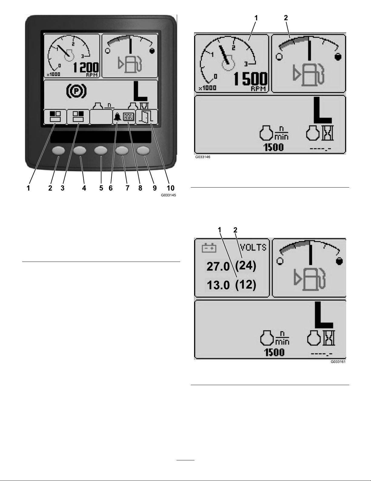
1
2
3 4
5
6
7
8
9 10
G033145
1
2
G033146
Figure16
27.0
(24)
13.0
(12)
2
1
1.Tachometer2.Fuel-levelindicator
g033146
Figure15
1.Screen1—top,leftscreen
2.Button17.Button4
3.Screen2—top,right
screen
4.Button29.Button5
5.Button310.Exit
Pressbuttons1to4toaccessthepop-up-menubar
onthebottomofthescreen(Figure15).
Afterthestart-upscreenappears,youcanselectwhat
youwouldlikedisplayedinboththetop,leftcorner
andtop,rightcornerofthedisplayscreenbypressing
button1orbutton2ontheInfoCentercontrol(Figure
15).
6.Audiblealarm
8.Faultscreen
Note:Whenyoushutoffthemachine,thetop2
screenswillremainattheprevioussettingbeforethe
machinewasshutoff.
Youcantogglebetweenthefollowingscreensby
pressingbutton1andbutton2:
•Tachometer—top,leftscreenFigure16
•Fuel-levelindicator—top,rightscreen(Figure16)
g033145
•12Vbattery-voltageindicator—top,leftscreen
(Figure17)
•24Vbattery-voltageindicator—top,left
screen(Figure17)
g033161
Figure17
•Hydraulic-uid-temperatureandfanindicator—top,
rightscreen(Figure18)
Note:InexampleFigure18,the
hydraulic-uid-coolingfansarerunningat
25%speedintheforwarddirection.
•Engine-coolant-temperatureandfan
indicator—top,leftscreen(Figure18)
25
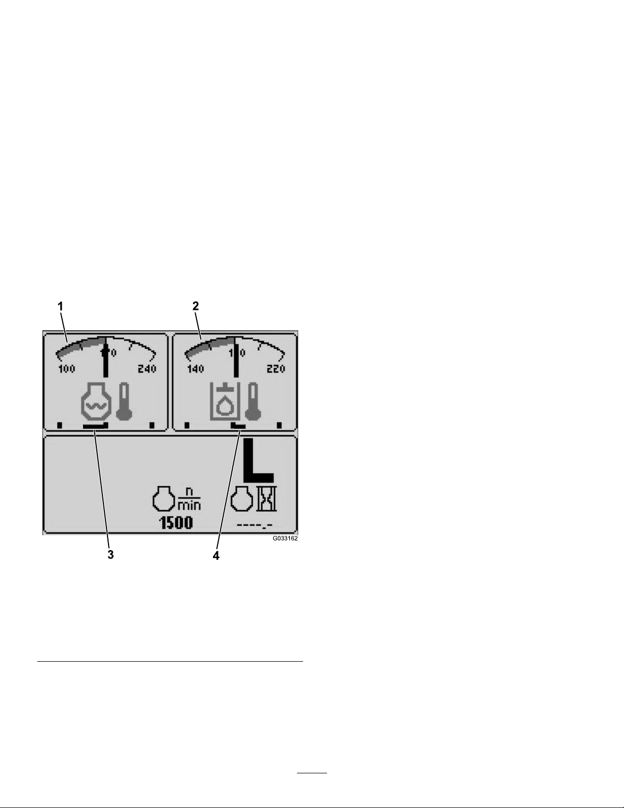
Note:InexampleFigure18,theengine-coolant
1
2
G033162
3
4
fansarerunningat50%speedinthereverse
direction.
Thisdisplayindicates(Figure14)fanspeedand
direction.Thefanspeediscontrolledbythe
hydraulic-uidtemperatureortheengine-coolant
temperature,andautomaticallyreversesas
needed.Areversecycleautomaticallyinitiatesto
helpblowdebrisofftherespectivehoodscreen,
wheneitherthetemperatureoftheenginecoolant
orthehydraulicuidreachesacertainpoint.
Additionally,theradiatorfansperformareverse
cycleevery21minutesregardlessofthecoolant
temperature.
Fandirectionisalsoindicatedonthe
engine-coolant-temperaturescreenandthe
hydraulic-uid-temperaturescreen.Ifthebaris
totherightofthemidpointhashmark,thefans
arerunningintheforwarddirection.Ifthebaristo
theleftofthemidpointhashmark,thefansare
runninginthereversedirection(Figure18).
Pressthearrowkeystonavigatethefaultscreen.
Pressanykeytorevealtheinformationkeysonthe
screen.
Diesel-Particulate-Filter(DPF)MaintenanceIndicator
Ifthediesel-particulate-lter(DPF)maintenance
indicator(Figure14)appearsonthescreen,
immediatelycontactyourTorodistributorforservice;
refertoDieselParticulateFilterRegeneration(page
48).
Fuel-LevelIndicator
Thisdisplayindicatestheleveloffuelinthetank
(Figure16).
PTOIndicator
Thisdisplayindicates(Figure14)whenthePTOis
engaged.
Parking-BrakeIndicator
Thisdisplayindicatesthattheparkingbrakeis
engaged(Figure14).
Cruise-ControlIndicator
Thisdisplay(Figure14)indicateswhenthecruise
controlisset.
H/L(High/LowRange)Speed-RangeIndicator
Thisdisplayindicatestheselectedtransmission
speedrange(Figure14).
Glow-PlugIndicator
Thisdisplayindicateswhentheengineispreheating
(Figure14).
Engine-HoursIndicator
Thisdisplayshowsthetotalhoursthattheenginehas
1.Engine-coolant-temperature
indicator
2.Hydraulic-uid-temperature
indicator
g033162
Figure18
3.Engine-coolantfans
runningat50%speedin
thereversedirection
4.Hydraulic-uid-cooling
fansrunningat25%speed
intheforwarddirection
beenoperated(Figure14).
Tachometer
Thisdisplayshowstheengine-operatingspeedinrpm
(Figure16).
Hydraulic-Fluid-TemperatureIndicatorand
Cooling-Fan-StatusIndicator
Ifafaultappearsonthescreen,pressanykeytoview
theactivefaultadvisory(Figure15).
Note:Contactyoursupervisorormechanictorelay
thefaultadvisoryanddeterminethecourseofaction.
Thisdisplayindicatesthehydraulic-uidtemperature
andthestatusofthecoolingfan(Figure18).
Engine-Coolant-TemperatureIndicatorand
Cooling-Fan-StatusIndicator
Thisdisplayindicatestheengine-coolanttemperature
andthestatusofthecoolingfan(Figure18).
26
BatteryVoltage
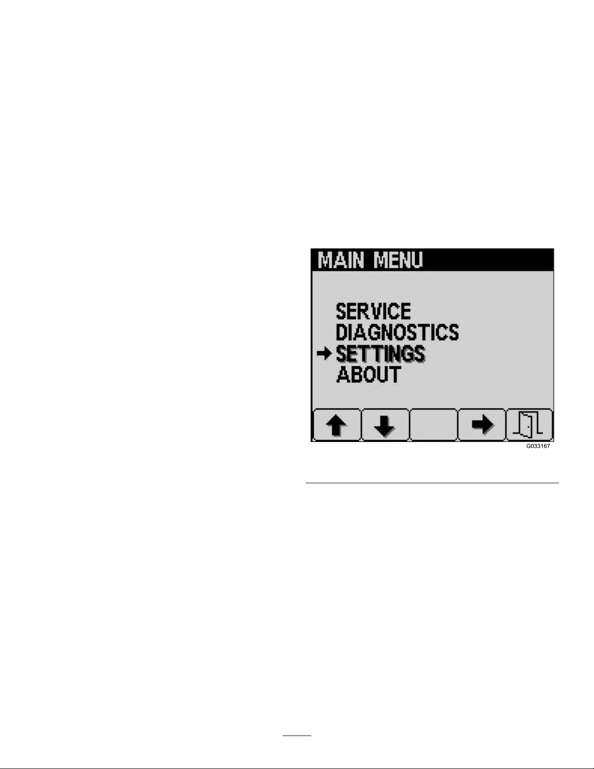
MainMenu
Thisdisplayshowsboththe12Vand24Vbattery
voltage(Figure17).
Service-DueIndicator
Thisdisplayindicatesthetimeuntilthenextregular
serviceinterval.
Note:Afteryouservicethemachine,resetthe
indicator.
1.Pressandholdthefar,rightbuttononthe
InfoCenter.
Note:TheMainMenuscreenappears.
2.SelectServiceusingthe2buttonsonthe
left;pressthebuttonbelowtherightarrowto
continue.
3.SelectHoursandpressthebuttonbelowthe
rightarrow.
4.PressthebuttonbelowResetHours.
5.SelecttheHoursfortheappropriatenextservice
timeandpressthebuttonbelowtherightarrow.
Note:Acheckmarkappearsoncetheindicator
hasbeenreset.
Pressandholdthefthbutton(farright)onthe
InfoCentertoaccessthemainmenu.
Fromthemainmenuscreen,youcanaccessthe
Servicescreen,Diagnosticsscreen,Settingsscreen,
ortheAboutscreen(Figure19).
ServiceScreen
IfyouhaveanissuethatrequiresuseoftheService
screen(i.e.,calibratingthetractionpedal),contact
yourAuthorizedToroServiceDealerforassistance.
InfoCenterPINEntry
1.Fromthestart-upscreen,pressandholdbutton
5untiltheMainMenuappears(Figure19).
6.Whenyouarenished,pressthebuttonbelow
theexiticon(pictureofanopendoor)toreturn
tothemainscreen,orpresscanceltoexit.
AudibleAlarm(InfoCenter)
Thealarmsoundsduringthefollowingscenarios:
Loweringthedeck
•Theengineisnotrunning
•Anydeckisbeinglowered
Deckisoutofoat
•ThePTOisrequestedandqualied
•Anydeckisbelowthelimit,butnotoating
MachinesendsarequesttotheInfoCenter
•Theenginesendsared,stoplampmessage
Note:Ifthealarmstopsoriftheoperator
acknowledgesthealarmbypressinganybutton
ontheInfoCenter,thenthealarmshouldstop.
•Regenerationrequestedbytheengine
g033167
Figure19
2.Pressbutton2untilyoureachSettingsonthe
MainMenuscreenandpressbutton4toselect
Settings(Figure19).
3.FromtheSettingsscreen,pressbutton4to
selectDisplay(Figure20).
•Anyenginefault
•Anyadvisory;refertoInfoCenterAdvisories(page
31)
•Theenginesendsanamber-warningmessage
•Thefuellevelisbelow2.2%
27
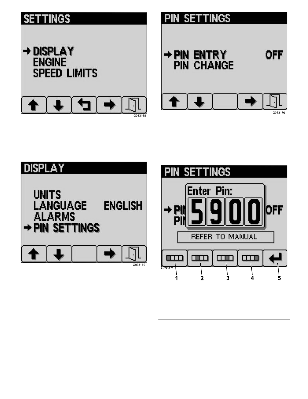
Figure20
1
2
3
4
5
G033171
g033168
Figure22
g033170
4.Pressbutton2untilyoureachPINSettingson
theDisplayscreenandpressbutton4toselect
PINSettings(Figure21).
Figure21
5.FromthePINSettingscreen,pressbutton4to
selectPINEntry(Figure22).
6.EnterthedefaultPIN,5900,intotheEnterPIN
screenbyusingbuttons1to4toselectthe
digitsandpressbutton5tocompletethePIN
(Figure23).
g033169
g033171
Figure23
1.Digit14.Digit4
2.Digit25.EnterPIN
3.Digit3
28

ChangingtheInfoCenterPIN
1 2 3
4
5
1 2 3
4
5
1 2 3
4
5
1.Fromthestart-upscreen,pressandholdbutton
5untiltheMainMenuappears(Figure19).
2.Pressbutton2untilyoureachSettingsonthe
MainMenuscreenandpressbutton4toselect
Settings(Figure19).
3.FromtheSettingsscreen,pressbutton4to
selectDisplay(Figure20).
4.Pressbutton2untilyoureachPINSettingson
theDisplayscreenandpressbutton4toselect
PINSettings(Figure21).
5.Pressbutton2untilyoureachPINChangeon
thePINSettingsscreenandpressbutton4to
selectPINChange(Figure22).
6.EnteryouroldPINusingbuttons1to4andpress
button5whenyoucompletethePIN(Figure24).
Note:ThedefaultPINwhenyouinitiallysetup
yourPINis5900.
g033173
Figure25
1.Digit14.Digit4
2.Digit25.EnterPIN
3.Digit3
Figure24
1.Digit14.Digit4
2.Digit25.EnterPIN
3.Digit3
7.EnteryournewPINusingbuttons1to4and
pressbutton5whenyoucompleteyournew
PIN(Figure25).
8.ConrmyournewPINusingbuttons1to4and
pressbutton5whenyoucompletethePIN
(Figure26).
g033172
g033174
Figure26
1.Digit14.Digit4
2.Digit25.EnterPIN
3.Digit3
29
ChangingtheInfoCenterDisplay
1 2 3
4
5
1
G033179
1
+
2 3
G033180
Brightness/Contrast
1.Fromthestart-upscreen,pressbutton5to
accessthebrightness/contrastpop-up-menu
bar(Figure27).
g033179
Figure28
1.Cruise-controlselection
Figure27
1.Decreasebrightness4.Increasecontrast
2.Increasebrightness5.Exit
3.Decreasecontrast
2.Pressbutton1todecreasebrightness,button
2toincreasebrightness,button3todecrease
contrast,andbutton4toincreasecontrast
(Figure27).
3.Whenyouhavesetyourbrightness/contrast,
pressbutton5toexit(Figure27).
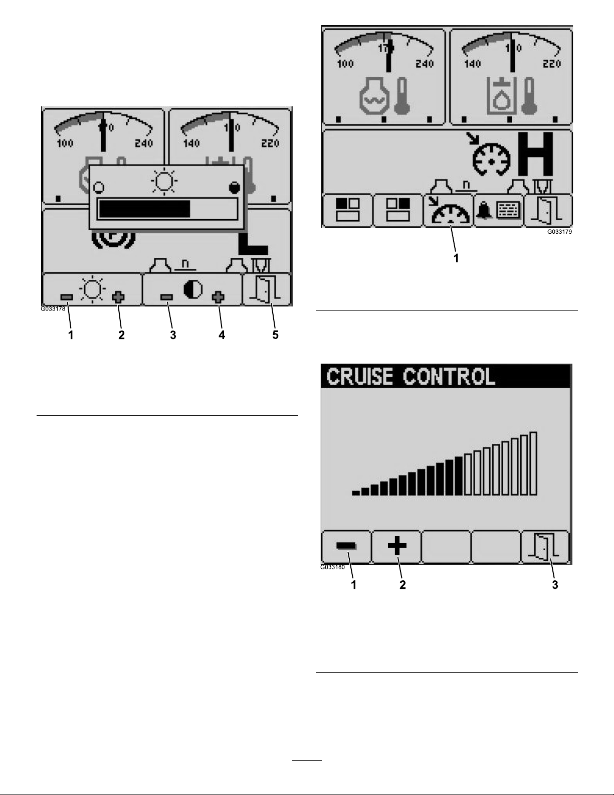
SettingtheCruise-ControlSpeed
Youcansetthecruise-controlspeedbymovingthe
cruise-controlswitchmomentarilyforward,viathe
Infocenterasfollows:
1.Movethecruise-controlswitchtotheONposition
(Figure10).
2.Whenthecruise-controliconappearsonthe
displayscreen,pressbutton1to4toaccessthe
pop-up-menubar.
3.Pressbutton3toaccesstheCruiseControl
screen(Figure28)˙.
4.FromtheCruiseControlscreen,pressbutton1
g033178
todecreasethecruise-controlspeedorbutton2
toincreasethecruise-controlspeed(Figure29).
Figure29
1.Decreasecruise-control
speed
2.Increasecruise-control
speed
3.Exit
g033180
5.Whenyouhavesetyourdesiredcruise-control
speed,pressbutton5toexit(Figure29).
30
 Loading...