

Page 1
FormNo.3403-582RevB
Groundsmaster
®
5900and5910
RotaryMower
ModelNo.31698—SerialNo.316000001andUp
ModelNo.31699—SerialNo.316000001andUp
Registeratwww.T oro.com.
OriginalInstructions(EN)
*3403-582*B
Page 2
ThisproductcomplieswithallrelevantEuropean
directives;fordetails,pleaseseetheseparateproduct
specicDeclarationofConformity(DOC)sheet.
WARNING
CALIFORNIA
Proposition65Warning
Thisproductcontainsachemical
orchemicalsknowntotheStateof
Californiatocausecancer,birthdefects,
orreproductiveharm.
Dieselengineexhaustandsomeofits
constituentsareknowntotheStateof
Californiatocausecancer,birthdefects,
andotherreproductiveharm.
ItisaviolationofCaliforniaPublicResourceCode
Section4442or4443touseoroperatetheengineon
anyforest-covered,brush-covered,orgrass-covered
landunlesstheengineisequippedwithaspark
arrester,asdenedinSection4442,maintainedin
effectiveworkingorderortheengineisconstructed,
equipped,andmaintainedforthepreventionofre.
g008833
Figure1
Introduction
Thismachineisaride-on,rotary-bladelawnmower
intendedtobeusedbyprofessionaloperatorsin
commercialapplications.Itisdesignedprimarilyfor
mowinggrassonwell-maintainedlawnsinparks,
golfcourses,sportselds,alongroadways,andon
commercialgrounds.Itisnotdesignedformowing
brushorforagriculturaluses.
Readthisinformationcarefullytolearnhowtooperate
andmaintainyourproductproperlyandtoavoid
injuryandproductdamage.Youareresponsiblefor
operatingtheproductproperlyandsafely .
YoumaycontactTorodirectlyatwww.Toro.com
forproductsafetyandoperationtrainingmaterials,
accessoryinformation,helpndingadealer,orto
registeryourproduct.
Wheneveryouneedservice,genuineToroparts,or
additionalinformation,contactanAuthorizedService
DealerorToroCustomerServiceandhavethemodel
andserialnumbersofyourproductready.Figure1
identiesthelocationofthemodelandserialnumbers
ontheproduct.Writethenumbersinthespace
provided.
1.Modelandserialnumberlocation
ModelNo.
SerialNo.
Thismanualidentiespotentialhazardsandhas
safetymessagesidentiedbythesafety-alertsymbol
(Figure2),whichsignalsahazardthatmaycause
seriousinjuryordeathifyoudonotfollowthe
recommendedprecautions.
g000502
Figure2
1.Safety-alertsymbol
Thismanualuses2wordstohighlightinformation.
Importantcallsattentiontospecialmechanical
informationandNoteemphasizesgeneralinformation
worthyofspecialattention.
©2017—TheToro®Company
8111LyndaleAvenueSouth
Bloomington,MN55420
Contactusatwww.Toro.com.
2
PrintedintheUSA
AllRightsReserved
Page 3

Contents
Safety.......................................................................4
GeneralSafety...................................................4
SoundPowerLevel............................................4
SoundPressureLevel........................................5
VibrationLevel....................................................5
Engine-EmissionCertication.............................5
SafetyandInstructionalDecals..........................6
Setup......................................................................17
1RemovingtheWing-Deck-ShippingStraps
andBraces....................................................17
2LoweringtheFront-DeckWinglets.................17
3CheckingtheTireandCasterWheel
Pressure.......................................................19
4LevelingtheFront,CenterDeck.....................19
5LevelingtheWingletDeckstotheFront,
CenterDeck..................................................19
6CheckingtheFluidLevels..............................20
7GreasingtheMachine....................................20
ProductOverview...................................................21
Controls...........................................................22
CabControls.................................................23
InfoCenterControl.........................................24
Specications..................................................34
Attachments/Accessories.................................34
BeforeOperation.................................................35
BeforeOperationSafety...................................35
CheckingtheEngine-OilLevel..........................36
CheckingtheCoolingSystems.........................36
CheckingtheHydraulicSystem........................36
FillingtheFuelTank..........................................36
CheckingtheTirePressure...............................37
CheckingtheCasterWheelTire
Pressure.......................................................37
CheckingtheT orqueoftheWheel-Lug
Nuts..............................................................38
AdjustingtheHeightofCut...............................38
AdjustingtheSkids...........................................40
AdjustingtheMowerDeckAnti-Scalp
Rollers...........................................................41
CheckingaMismatchBetweenMower
Decks............................................................42
AdjustingtheMirrors.........................................44
AimingtheHeadlights.......................................44
CheckingtheSafety-InterlockSwitches............44
CheckingtheBladeStoppingTime...................45
DuringOperation.................................................45
DuringOperationSafety...................................45
StartingandStoppingtheEngine......................46
RaisingorLoweringtheDecks..........................47
CuttingGrasswiththeMachine........................47
DieselParticulateFilterRegeneration...............48
UnderstandingtheOperatingCharacteristics
oftheMachine..............................................56
Understandingthe12Vand24VElectrical
Systems........................................................56
AutomaticReversing-FanCycle.......................56
OperatingTips.................................................57
AfterOperation....................................................58
AfterOperationSafety......................................58
PushingorT owingtheMachine........................58
IdentifyingtheTie-DownPoints........................59
HaulingtheMachine.........................................59
Maintenance...........................................................60
RecommendedMaintenanceSchedule(s)...........60
DailyMaintenanceChecklist.............................61
Service-IntervalChart.......................................63
Pre-MaintenanceProcedures..............................64
Pre-MaintenanceSafety...................................64
UsingtheBattery-DisconnectSwitch................64
RaisingtheMachine.........................................65
RemovingandInstallingthe
Inner-Wing-DeckCovers...............................65
Lubrication..........................................................66
GreasingtheBearingsandBushings................66
EngineMaintenance...........................................69
EngineSafety...................................................69
ServicingtheAirCleaner..................................69
ServicingtheEngineOil....................................71
AdjustingtheEngine-ValveClearance..............73
CleaningtheEngineEGRCooler......................73
InspectingtheEngineCrankcase-Breather
System..........................................................73
CheckingandReplacingFuelHosesand
Engine-CoolantHoses..................................73
LappingorAdjustingtheEngineIntakeand
ExhaustValves.............................................73
InspectingandCleaning
Engine-Emission-ControlComponents
andTurbocharger.........................................74
ServicingtheDiesel-OxidationCatalyst
(DOC)andtheSootFilter..............................74
FuelSystemMaintenance...................................75
ServicingtheFuelSystem................................75
ServicingtheWaterSeparator.........................75
ReplacingtheFuelFilterElement.....................76
ElectricalSystemMaintenance...........................76
ElectricalSystemSafety...................................76
LocatingtheFuses...........................................76
CheckingtheConditionoftheBatteries.............78
ChargingtheBatteries......................................78
Jump-StartingtheMachine...............................79
DriveSystemMaintenance..................................80
CalibratingtheTractionPedal...........................80
AdjustingtheTraction-PedalAngle...................80
CheckingtheRearWheelToe-In......................80
CoolingSystemMaintenance..............................81
CoolingSystemSafety.....................................81
CheckingtheEngine-CoolingSystem...............81
CleaningtheCoolingSystems..........................82
ChangingtheEngine-Cooling-System
Fluid..............................................................83
BeltMaintenance................................................84
Servicingthe12VAlternatorBelt......................84
3
Page 4

Servicingthe24VAlternatorBeltandAC
CompressorBelt...........................................84
ReplacingtheBlade-DriveBelts.......................84
HydraulicSystemMaintenance...........................86
HydraulicSystemSafety...................................86
CheckingtheHydraulicFluid............................86
ChangingtheHydraulicFluidand
Filters............................................................87
CheckingtheHydraulicLinesand
Hoses............................................................88
InspectingtheHydraulicSystemT est
Ports.............................................................88
MowerMaintenance.............................................89
Pivoting(Tilting)theFrontMowerDeck
Upright..........................................................89
Pivoting(Tilting)theFrontMowerDeck
Down.............................................................90
AdjustingtheMower-DeckPitch.......................90
ServicingtheCaster-ArmBushings..................91
ServicingtheCasterWheelsand
Bearings........................................................91
BladeMaintenance..............................................92
BladeSafety.....................................................92
CheckingforaBentBlade................................92
RemovingandInstallingaBlade.......................92
InspectingandSharpeningaBlade...................93
CorrectingaMower-DeckMismatch.................93
CabMaintenance.................................................94
CleaningtheCab..............................................94
CleaningtheCabAirFilters..............................94
CleaningtheAir-Conditioning-Condenser
Coil...............................................................95
Storage...................................................................95
PreparingtheMachineforStorage...................95
Safety
Thismachinehasbeendesignedinaccordancewith
ENISO5395:2013andANSIB71.4-2012.
GeneralSafety
Thisproductiscapableofamputatinghandsand
feetandofthrowingobjects.Alwaysfollowallsafety
instructionstoavoidseriouspersonalinjury.
Usingthisproductforpurposesotherthanitsintended
usecouldprovedangeroustoyouandbystanders.
•Readandunderstandthecontentsofthis
Operator’sManualbeforeyoustarttheengine.
Ensurethateveryoneusingthisproductknows
howtouseitandunderstandsthewarnings.
•Donotputyourhandsorfeetnearmoving
componentsofthemachine.
•Donotoperatethemachinewithoutallguards
andothersafetyprotectivedevicesinplaceand
workingonthemachine.
•Keepclearofanydischargeopening.Keep
bystandersasafedistancefromthemachine.
•Keepchildrenoutoftheoperatingarea.Never
allowchildrentooperatethemachine.
•Stopthemachineandshutofftheenginebefore
servicing,fueling,oruncloggingthemachine.
Improperlyusingormaintainingthismachinecan
resultininjury.Toreducethepotentialforinjury,
complywiththesesafetyinstructionsandalwayspay
attentiontothesafety-alertsymbol,whichmeans
Caution,Warning,orDanger—personalsafety
instruction.Failuretocomplywiththeseinstructions
mayresultinpersonalinjuryordeath.
Youcanndadditionalitemsofsafetyinformationin
theirrespectivesectionsthroughoutthismanual.
SoundPowerLevel
Model31698
Thisunithasaguaranteedsoundpowerlevelof105
dBA,whichincludesanUncertaintyValue(K)of1.0
dBA.
Soundpowerlevelwasdeterminedaccordingtothe
proceduresoutlinedinISO11094.
Model31699
Thisunithasaguaranteedsoundpowerlevelof105
dBA,whichincludesanUncertaintyValue(K)of1.0
dBA.
4
Page 5

Soundpowerlevelwasdeterminedaccordingtothe
proceduresoutlinedinISO11094.
SoundPressureLevel
Model31698
Thisunithasasoundpressurelevelattheoperator’s
earof90dBA,whichincludesanUncertaintyV alue
(K)of1.0dBA.
VibrationLevel
Hand-Arm
Model31698
Measuredvibrationlevelforrighthand=0.8m/s
Measuredvibrationlevelforlefthand=1.0m/s
UncertaintyValue(K)=0.5m/s
2
2
2
Soundpressurelevelwasdeterminedaccordingto
theproceduresoutlinedinENISO5395:2013.
Model31699
Thisunithasasoundpressurelevelattheoperator’s
earof82dBA,whichincludesanUncertaintyV alue
(K)of1.0dBA.
Soundpressurelevelwasdeterminedaccordingto
theproceduresoutlinedinENISO5395:2013.
CAUTION
Long-termexposuretonoisewhileoperating
themachinemaycausesomehearingloss.
Wearadequatehearingprotectionwhenever
youoperatethemachineforanextended
periodoftime.
Measuredvaluesweredeterminedaccordingtothe
proceduresoutlinedinENISO5395:2013.
Model31699
Measuredvibrationlevelforrighthand=0.8m/s
Measuredvibrationlevelforlefthand=1.0m/s
UncertaintyValue(K)=0.5m/s
Measuredvaluesweredeterminedaccordingtothe
proceduresoutlinedinENISO5395:2013.
2
WholeBody
Model31698
Measuredvibrationlevel=0.35m/s
UncertaintyValue(K)=0.18m/s
Measuredvaluesweredeterminedaccordingtothe
proceduresoutlinedinENISO5395:2013.
2
2
2
2
Model31699
Measuredvibrationlevel=0.35m/s
UncertaintyValue(K)=0.18m/s
Measuredvaluesweredeterminedaccordingtothe
proceduresoutlinedinENISO5395:2013.
2
2
Engine-Emission
Certication
TheengineinthismachineisEP ATier4FinalandEU
Stage3bemissionscompliant.
5
Page 6
SafetyandInstructionalDecals
Safetydecalsandinstructionsareeasilyvisibletotheoperatorandarelocatednearanyarea
ofpotentialdanger.Replaceanydecalthatisdamagedorlost.
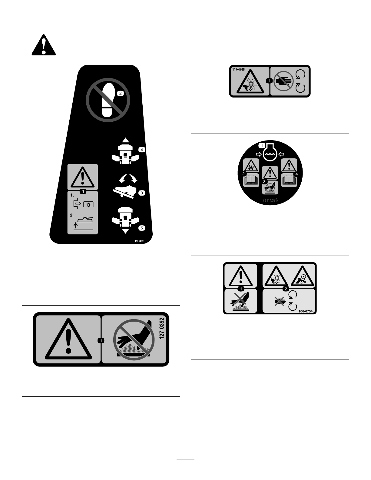
decal117-4766
117-4766
1.Cutting/dismembermenthazard,fan—stayawayfrom
movingparts;keepallguardsandshieldsinplace.
114-0849
1.Warning—disengagethePTOthenraisethedeck.
2.Nostep
3.Traction-controlpedal
4.Forward
5.Reverse
127-0392
decal117-3276
117-3276
1.Enginecoolantunder
pressure
2.Explosionhazard—read
decal114-0849
theOperator'sManual.
3.Warning—donottouchthe
hotsurface.
4.Warning—readthe
Operator'sManual.
decal106-6754
106-6754
1.Warning—donottouchthehotsurface.
2.Cutting/dismembermenthazard,fanandentanglement
hazard,belt—stayawayfrommovingparts.
decal127-0392
1.Warning—keepawayfromhotsurfaces.
6
Page 7
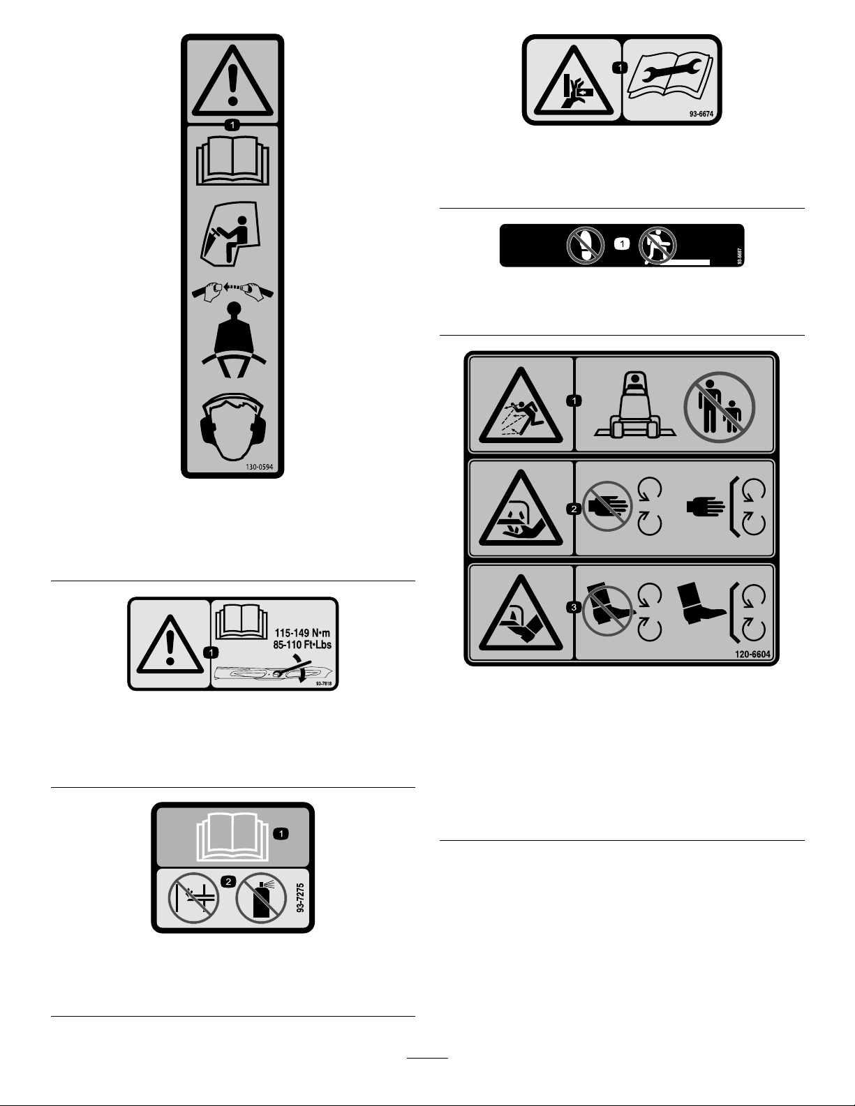
130-0594
ModelwithCabOnly
decal93-6674
93-6674
1.Crushinghazard,hand—readtheinstructionsbefore
servicingorperformingmaintenance.
decal93-6687
93-6687
1.Donotstephere.
decal130-0594
1.Warning—readtheOperator’sManual;whensittinginthe
cab,alwayswearaseatbelt;wearhearingprotection.
93-7818
1.Warning—readtheOperator'sManualforinstructionson
torquingthebladebolt/nutto1 15to149N·m(85to1 10
ft-lb).
93-7275
decal120-6604
decal93-7818
120-6604
1.Thrownobjecthazard—keepbystandersawayfromthe
machine.
2.Cutting/dismembermenthazardofhand,mower
blade—stayawayfrommovingparts;keepallguardsand
shieldsinplace.
3.Cutting/dismembermenthazardoffoot,mowerblade—stay
awayfrommovingparts;keepallguardsandshieldsin
place.
decal93-7275
1.ReadtheOperator’sManual—donotusestartinguidto
starttheengine.
7
Page 8
114-0922
decal114-0922
114-0922
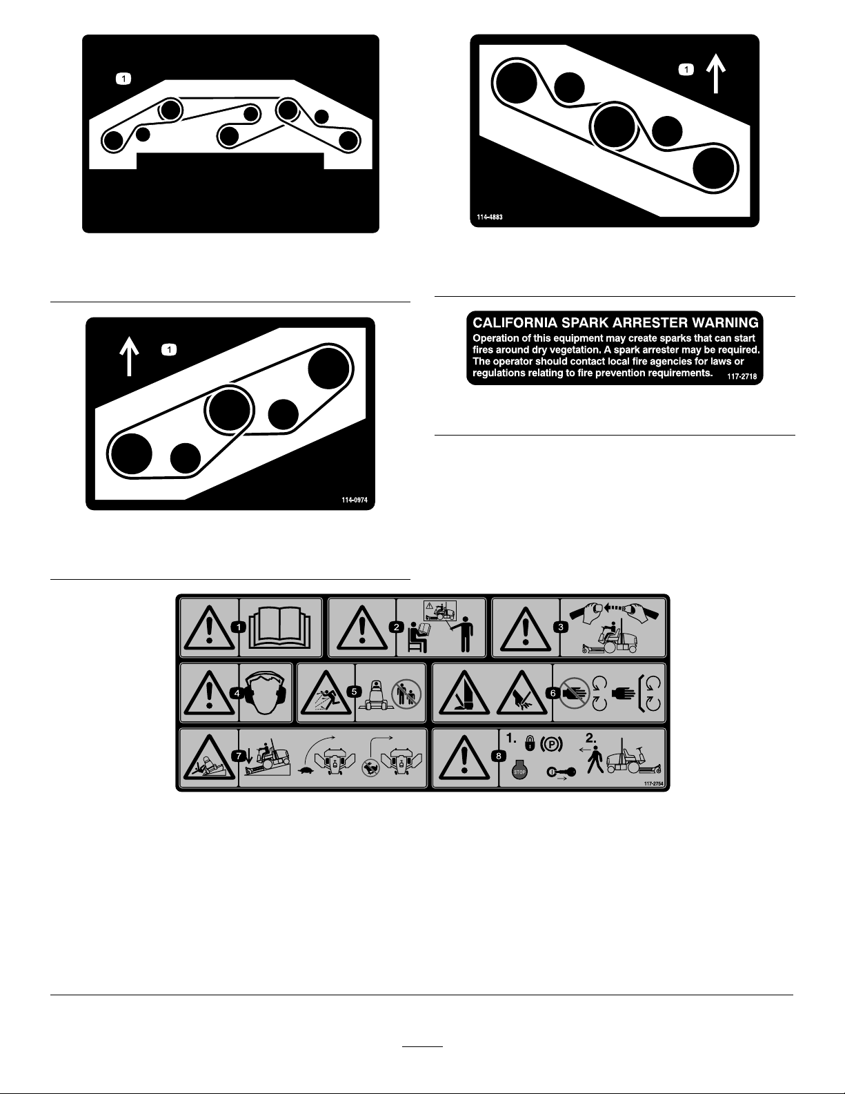
1.Beltrouting
1.Beltrouting
114-4883
decal114-4883
decal117-2718
117-2718
decal114-0974
114-0974
1.Beltrouting
117-2754
1.Warning—readtheOperator'sManual.
2.Warning—donotoperatethismachineunlessyouaretrained.
3.Warning—weartheseatbeltwhenseatedintheoperator'sposition.
4.Warning—wearhearingprotection.
5.Thrownobjecthazard—keepbystandersasafedistancefromthemachine.
6.Cuttinghazardofhandorfoot—stayawayfrommovingparts;keepallguardsinplace.
7.Tippinghazard—lowerthecuttingunitwhendrivingdownslopes;slowmachinebeforeturning;donotturnathighspeeds
8.Warning—settheparkingbrake,stoptheengine,andremovetheignitionkeybeforeleavingthemachine.
8
decal117-2754
Page 9
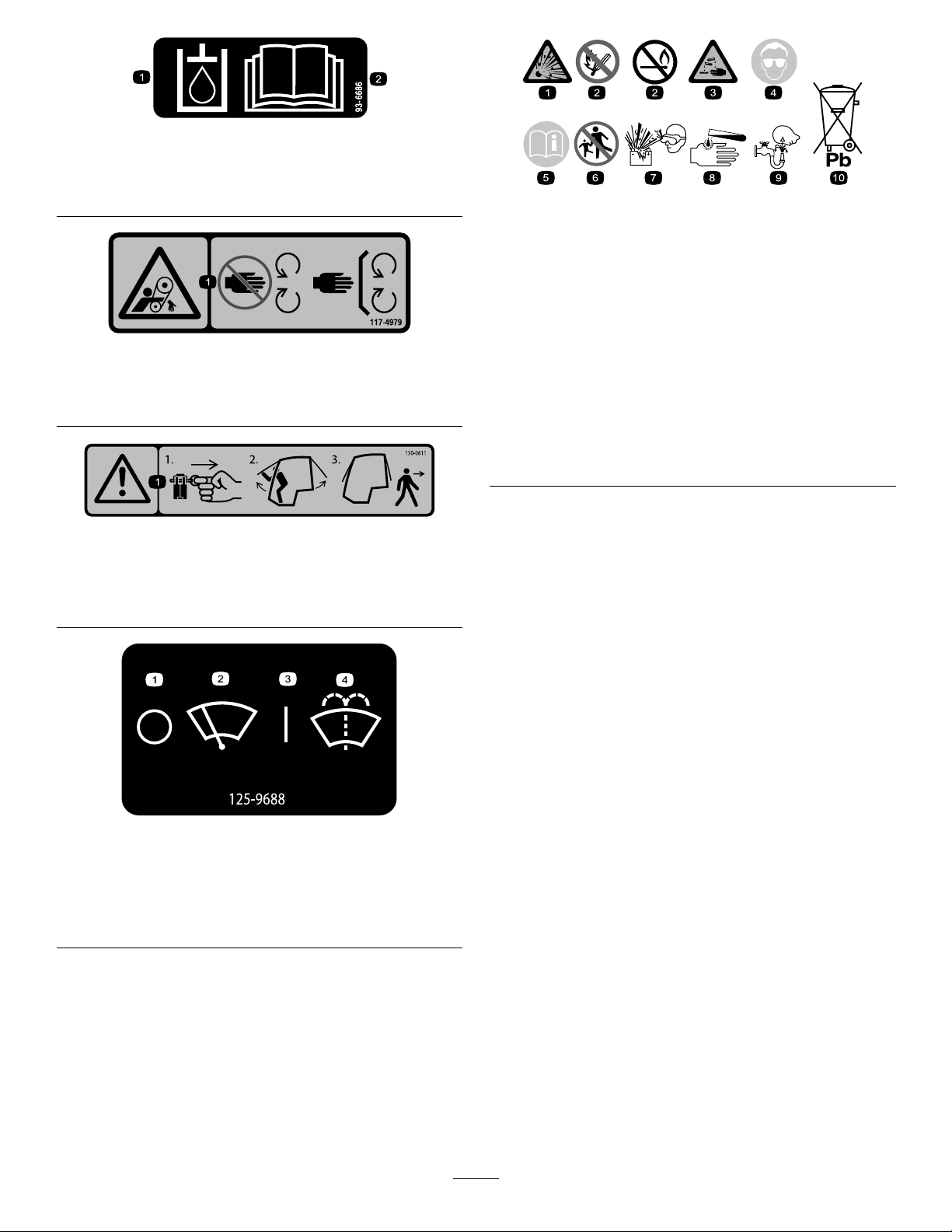
1.Hydraulicoil
2.ReadtheOperator'sManual.
decal93-6686
93-6686
decalbatterysymbols
BatterySymbols
Someorallofthesesymbolsareonyourbattery .
117-4979
1.Entanglementhazard,belt—stayawayfrommovingparts;
keepallguardsandshieldsinplace.
130-0611
ModelwithCabOnly
1.Warning—1)Removethepin;2)Raisethedoors;3)Exit
thecab
decal117-4979
decal130-0611
1.Explosionhazard
2.Nore,opename,or
6.Keepbystandersasafe
7.Weareyeprotection;
smoking
3.Causticliquid/chemical
8.Batteryacidcancause
burnhazard
4.Weareyeprotection.9.Flusheyesimmediately
5.ReadtheOperator's
10.Containslead;donot
Manual.
distancefromthebattery.
explosivegasescan
causeblindnessandother
injuries.
blindnessorsevereburns.
withwaterandgetmedical
helpfast.
discard.
ModelwithCabOnly
1.Windshieldwipers—off
2.Windshieldwipers
decal125-9688
125-9688
3.Windshieldwipers—on
4.Spraywindshieldwasher
uid
9
Page 10
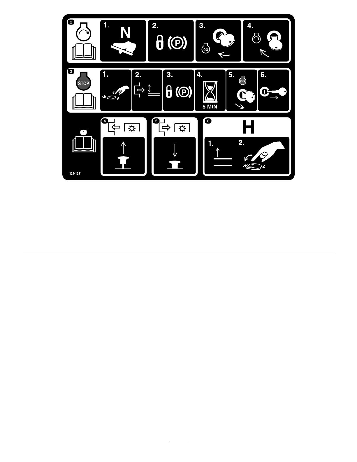
132-1321
1.ReadtheOperator’sManual.4.ToengagethePTO,pulluptheknob.
2.Tostarttheengine:1)Putthetractionpedalinneutral;2)Set
theparkingbrake;3)Turnthekeytotherunposition;4)Turn
thekeytotheenginestartposition.
3.Toshutofftheengine:1)Movethethrottleswitchtoslow;
2)DisengagethePTO;3)Settheparkingbrake;4)Wait5
minutes;5)TurntheignitionkeytoStop;and6)Removethe
key.
5.TodisengagethePTO,pushdowntheknob.
6.Toswitchthetransmissiontohighspeed,fullyraisethe
attachmentsandswitchthespeedcontroltotheHIGHposition.
decal132-1321
10
Page 11
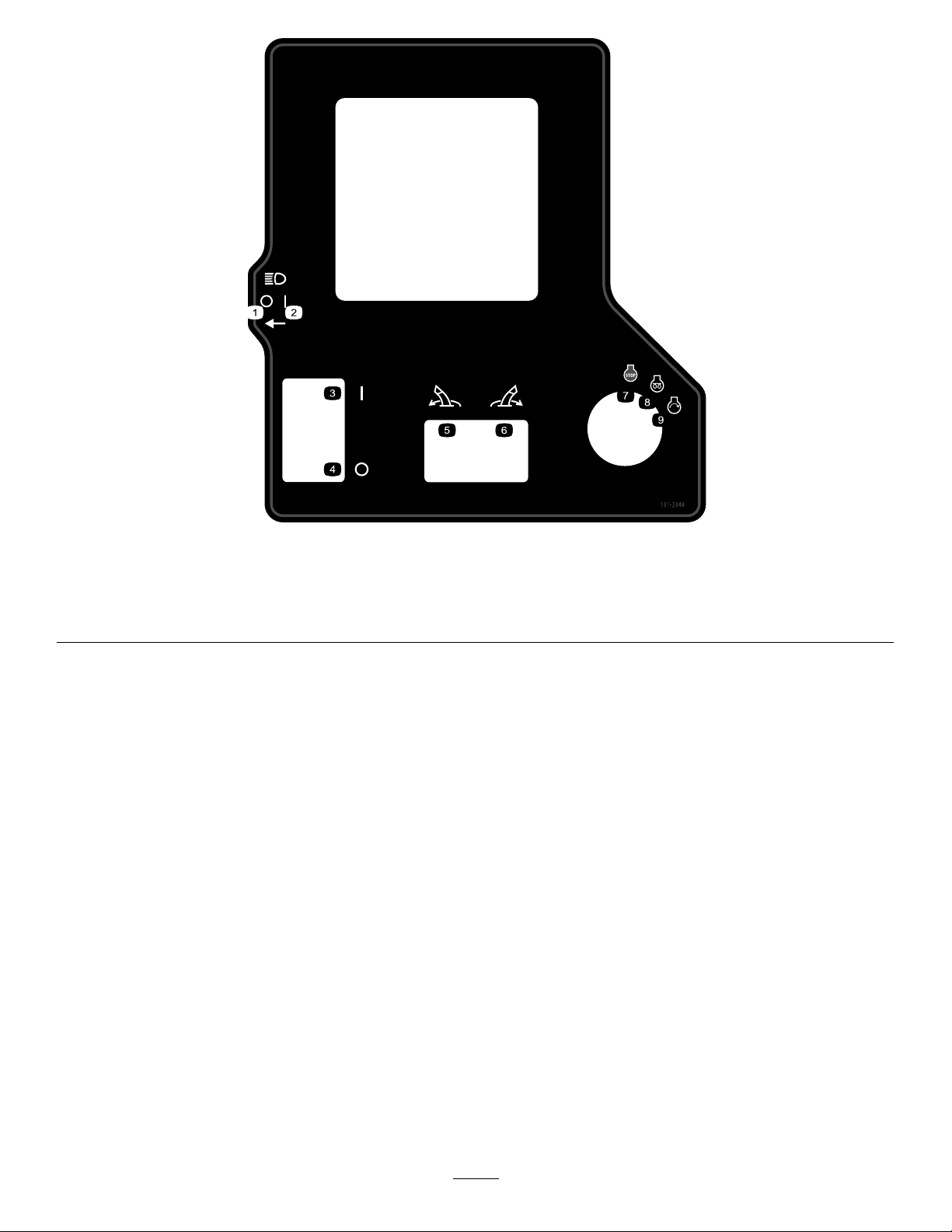
decal131-2348
131-2348
1.Headlights—off4.Parkingbrake—off
2.Headlights—on
5.Pivottheattachmentleft.
3.Parkingbrake—on6.Pivottheattachmentright.9.Engine—start
7.Engine—stop
8.Engine—run,electricpreheat
11
Page 12
132-3600
ModelwithCabOnly
decal132-3600
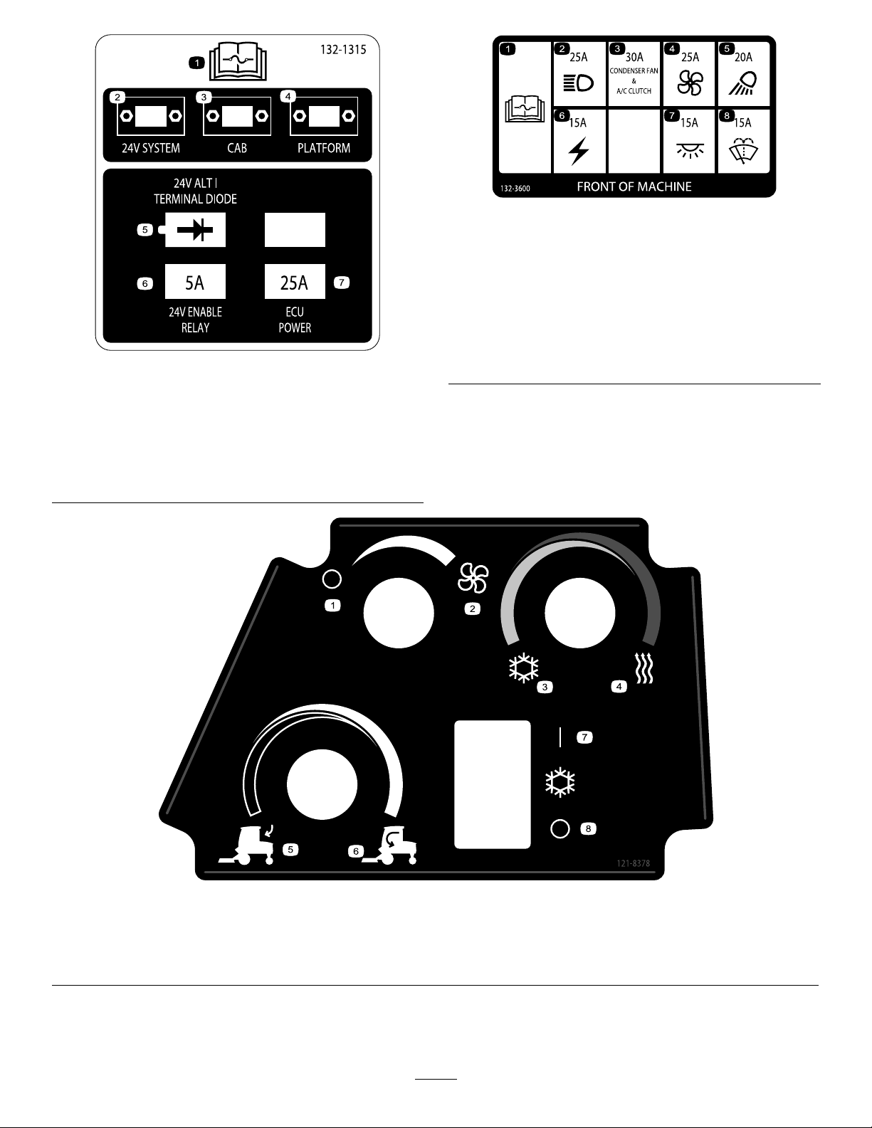
132-1315
1.ReadtheOperator's
Manualformore
informationonfuses.
2.24Vsystem6.24Venablerelay—5A
3.Cab7.ECUpower—25A
4.Platform
5.24Valt/terminaldiode
1.ReadtheOperator's
5.Workinglight—20A
Manualformore
informationonfuses.
2.Headlight—25A6.Auxiliarypower—15A
3.CondenserfanandA/C
7.Cablight—15A
clutch—30A
decal132-1315
4.Fan—25A8.Windshieldwipers—15A
1.Fan—off3.Coldair
2.Fan—onfull
4.Hotair6.Internalair
decal121-8378
121-8378
ModelwithCabOnly
5.Externalair7.Airconditioner—on
8.Airconditioner—off
12
Page 13
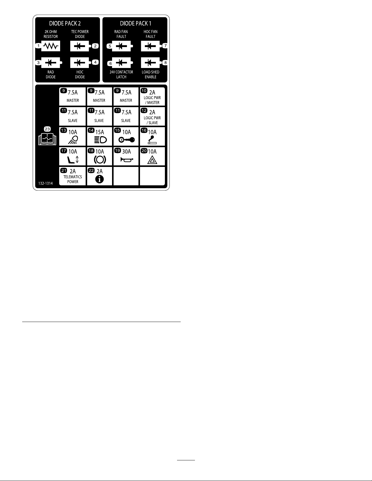
decal132-1314
132-1314
1.Resistor(2kOhm)
2.TECpowerdiode
13.Workinglight—10A
14.Headlight—15A
3.RADdiode15.Ignition—10A
4.HOCdiode16.Cigarettelighter—10A
5.RADfanfault
17.Electricseat—10A
6.Contactorlatch(24V)18.PTO—10A
7.HOCfanfault
19.Horn—30A
8.Loadshedenable20.Hazardlight—10A
9.Master—7.5A21.Telematicspower—2A
10.Logicpower/master—2A22.Infocenter—2A
11.Slave—7.5A23.Formoreinformationon
fuses,readtheOperator’s
Manual.
12.Logicpower/slave—2A
13
Page 14
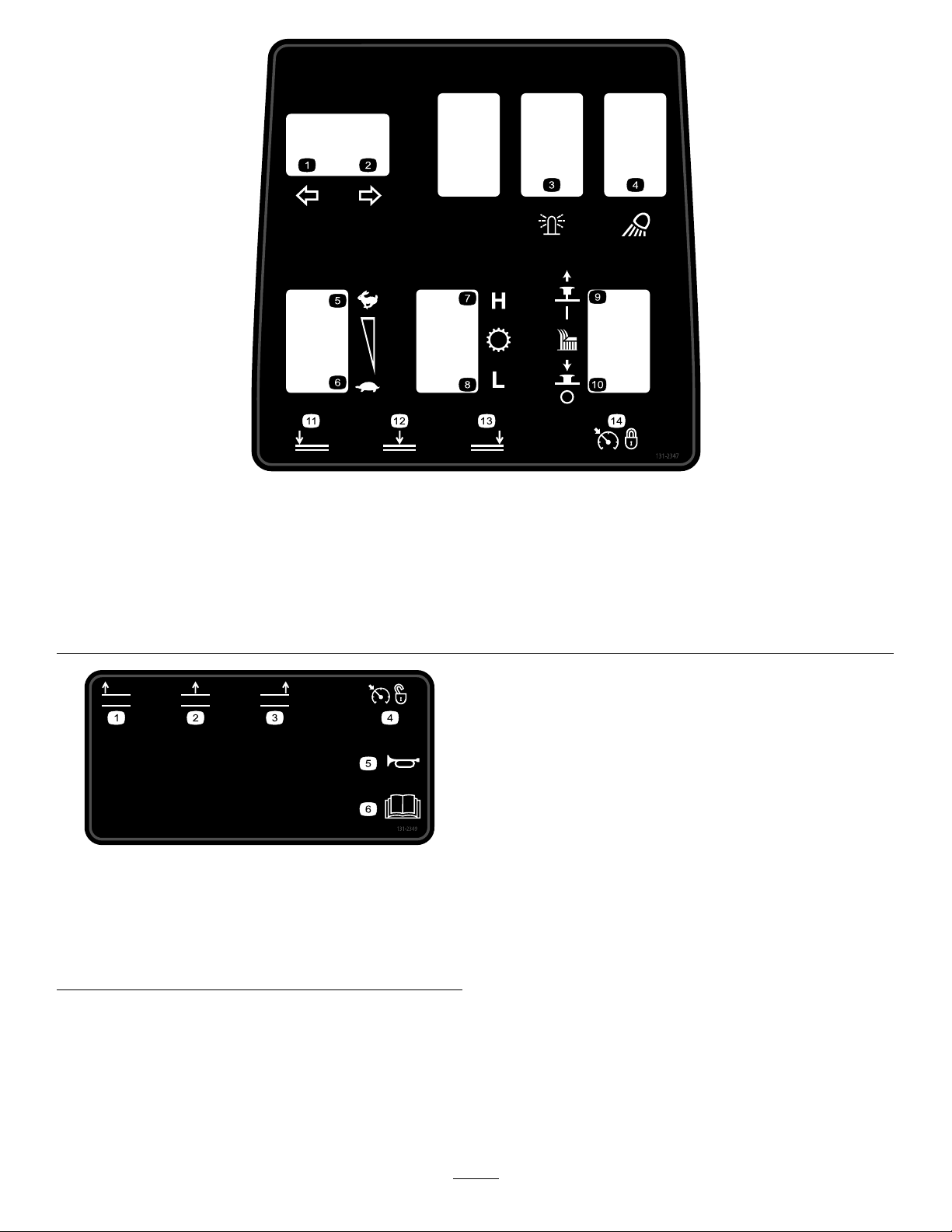
decal131-2347
131-2347
1.Left-turnsignal5.Enginespeed—fast
9.Pulluptoturnonthecutting
unit.
2.Right-turnsignal6.Enginespeed—slow
10.Pushdowntoturnoffthe
cuttingunit.
3.Beacon7.Transmission—highrange
11.Lowertheleftcuttingunit.
4.Worklight8.Transmission—lowrange12.Lowerthecentercutting
unit.
decal131-2349
131-2349
1.Raisetheleftcuttingunit.4.Cruisecontrol—off
2.Raisethecentercutting
unit.
3.Raisetherightcuttingunit.
5.Horn
6.ReadtheOperator's
Manual.
13.Lowertherightcuttingunit.
14.Cruisecontrol—set
14
Page 15
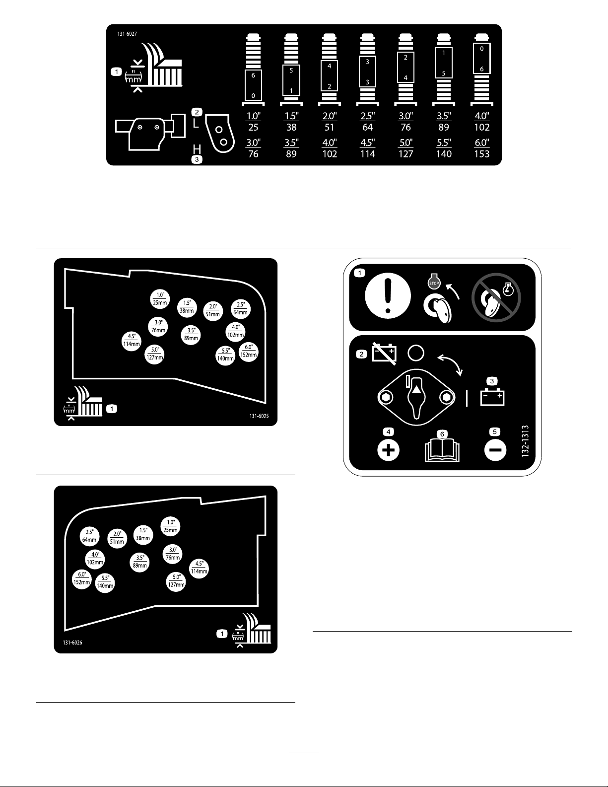
decal131-6027
131-6027
1.Height-of-cutsettings3.Lowercasterposition—heightsofcut76to153cm(3to6
inches)
2.Uppercasterposition—heightsofcut25to102cm(1to4
inches)
decal131-6025
131-6025
1.Heightofcut
132-1313
decal132-1313
1.Heightofcut
1.Attention—movethe
4.Positiveterminal
keytotheenginestop
positionbeforeservicing
thebattery;donotservice
thebatterywiththeengine
running.
2.Battery—disconnect5.Negativeterminal
3.Battery—connect
6.ReadtheOperator’s
Manualformore
informationonservicing
thebattery.
decal131-6026
131-6026
15
Page 16
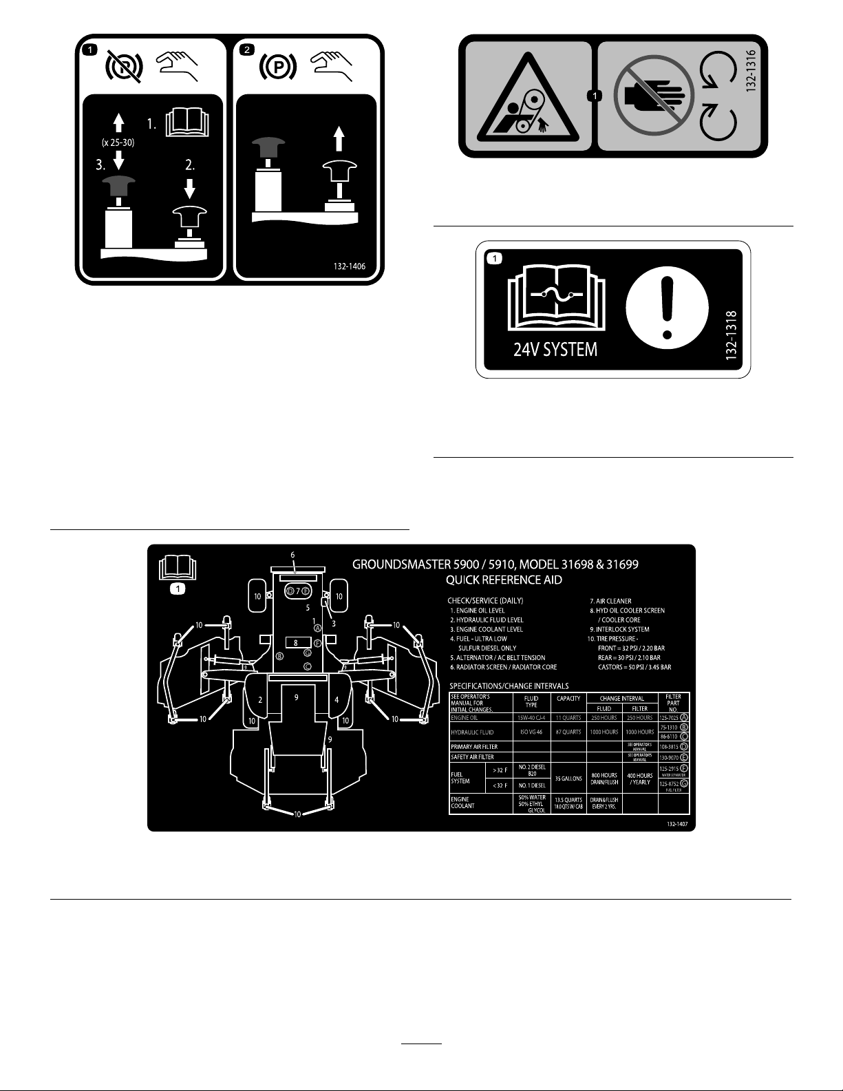
decal132-1316
132-1316
1.Entanglementhazard,belt—keepawayfrommovingparts.
decal132-1406
132-1406
1.Releasingtheparking
brakewhentheengine
isoff—1)Openthetow
valvesonthetraction
pump(readtheOperator's
Manual);2)Pushdown
andholdtheblackknobto
releasetheparkingbrake;
3)Workthehandpump
upanddown.Youcan
releasetheblackknob
after2to3pumps.The
parkingbrakewillrelease
after25to30pumps.
2.Engagingtheparking
brake—pulluponthe
blackknob;themanual
valveresetswhenyou
starttheengine.
decal132-1318
132-1318
1.Attention—readtheOperator'sManualforinformationon
fuses.
1.ReadtheOperator'sManualformoreinformationonservicingthemachine.
decal132-1407
132-1407
16
Page 17

Setup
LooseParts
Usethechartbelowtoverifythatallpartshavebeenshipped.
ProcedureDescription
1
2
3
4
5
6
7
MediaandAdditionalParts
Description
Nopartsrequired
Rightdeckcover1
Leftdeckcover
V-belt2
Nopartsrequired
Nopartsrequired
Nopartsrequired
Nopartsrequired
Nopartsrequired
Qty.
Qty.
Use
–
1
–
–
–
–
–
Removethewing-deck-shippingstraps
andbraces.
Lowerthefront-deckwinglets.
Checkthetireandcasterwheel
pressure.
Levelthefront,centerdeck.
Levelthewingletdeckstothefront,
centerdeck.
Checktheuidlevels.
Greasethemachine.
Use
Operator'sManual
Engineowner'smanual1
PartsCatalog
Operatortrainingmaterials
Declarationofconformity
Note:Determinetheleftandrightsidesofthe
machinefromthenormaloperatingposition.
1
1
1
1
Reviewitbeforeoperatingthemachine.
Useittoreferenceengineinformation.
Useittoreferencepartnumbersandorderreplacement
parts.
Readthematerialsbeforeoperatingthemachine.
ForCEcompliance
1
Removingthe Wing-Deck-ShippingStraps andBraces
NoPartsRequired
Procedure
Removethestrapsandbracessecuringthewing
decksforshipping.
17
Page 18
2
LoweringtheFront-Deck
Winglets
Partsneededforthisprocedure:
1Rightdeckcover
1
Leftdeckcover
2V-belt
Procedure
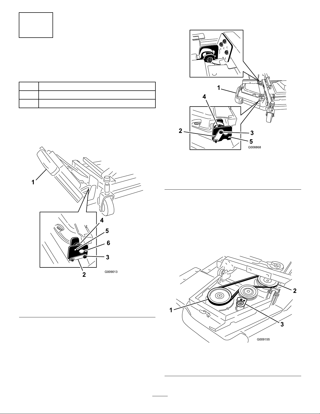
1.Removethenutssecuringthefrontandrearstop
boltstotherightwinglet-deckmounts(Figure3).
Note:Ensurethatthestopboltengagesthetab
onthehingepin.
g008868
Figure4
1.Winglet4.Eccentric
2.Hingepin5.Lowerhole
3.Bolt
Figure3
1.Winglet4.Eccentric
2.Hingepin5.Upperhole
3.Stopbolt
2.Whilesupportingtherightwinglet,removethe
frontandrearstopboltsfromthedeckmounts
(Figure3).
6.Deckmounts
Note:Leavetheeccentricspositionedbetween
thedeckmounts.
3.Lowerthewinglettotheoperatingposition.
4.Installthefrontandrearstopboltsthroughthe
upper-mountingholesandeccentrics(Figure4).
5.Installthenutssecuringthestopbolts.
Note:Donottightenthenutsatthistime.
6.Repeatthisprocedureonleftwinglet.
7.Installthewingletbeltsasfollows:
A.Startthebeltaroundthewinglet-spindle
pulleyandthefront-deck-spindlepulley
(Figure5).
g009013
g009155
Figure5
1.Winglet-spindlepulley3.Idlerpulley
2.Front-deck-spindlepulley
18
Page 19
B.Usingaratchetwrenchorasimilartool,
movetheidlerpulleyawayfromthepulleys
(Figure5).
C.Routethebeltaroundthewinglet-spindle
pulleyandtheupper-spindlepulleyonthe
frontdeck.
D.Releasetheidlerpulleytoputtensionon
thebelt.
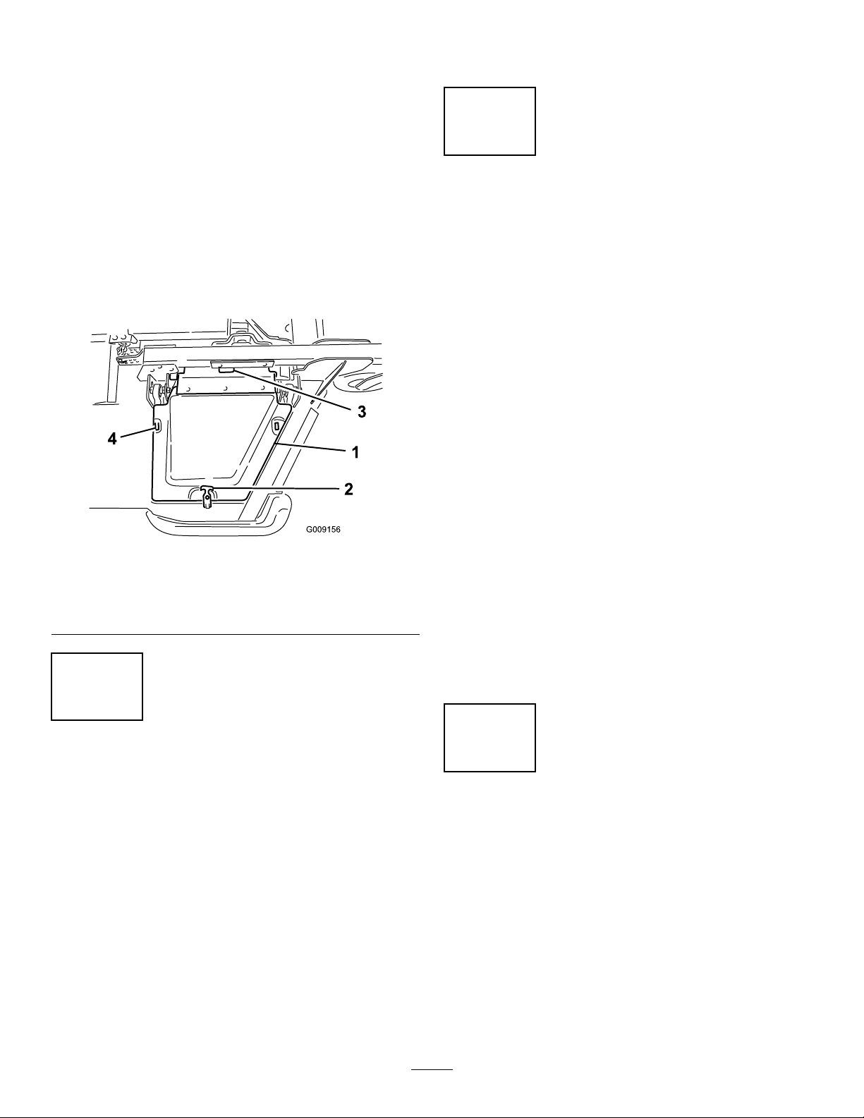
8.Installthewinglet-deckcoverandsecureitwith
therubberlatch(Figure6).
Note:Ensurethatyouslidethecoverunderthe
front,centerdeck-covertabsbeforeinsertingit
ontothemountinghooksandpost.
9.Repeatthisprocedureontheotherwinglet.
tiresizebetweenthefrontandreartires.Onlyuse
genuineTorotires.
4
LevelingtheFront,Center Deck
NoPartsRequired
Procedure
Note:Performthisprocedureonaat,levelsurface.
RefertoAdjustingtheHeightofCut(page38).
1.Rotatethebladeoneachouterspindleuntilthe
endsfaceforwardandbackward.
2.Measurefromtheoortothefronttipofthe
blade.
Figure6
1.Cover
2.Rubberlatch4.Mounthooks
3.Front,centerdeck-cover
tabs
3
CheckingtheTireand CasterWheelPressure
NoPartsRequired
Procedure
Checkthetireandcasterwheelpressurebeforeuse;
refertoCheckingtheTirePressure(page37)and
CheckingtheCasterWheelTirePressure(page37).
Important:Maintainpressureinalltiresto
ensureagoodquality-of-cutandpropermachine
performance.Donotunderinatethetires.
Important:Tractionperformance,including
tire-slipcontrol,isdependentontheratioofthe
3.Adjustthe3mm(1/8inch)shimsonthefront
casterfork(s)tomatchthedesiredheightofcut.
4.Rotatetheblades180°andmeasurefromthe
g009156
oortotherear-facingtipoftheblade.
5.Loosenthelowerjamnutsontheheight-of-cut
chainU-bolt.
6.Adjustthenutstoraiseorlowertherearofthe
mowerdecksothatthetipsoftherearblades
are6.35mm(1/4inch)to9.53mm(3/8inch)
higherthanthefronttips.
7.Tightenthejamnuts.
5
LevelingtheWingletDecks totheFront,CenterDeck
NoPartsRequired
Procedure
1.Rotatethebladeoneachwingletsothatitpoints
sidetoside.
2.Loosentheboltsandnutssecuringthe2
eccentricspacerstothewinglets(Figure7).
19
Page 20
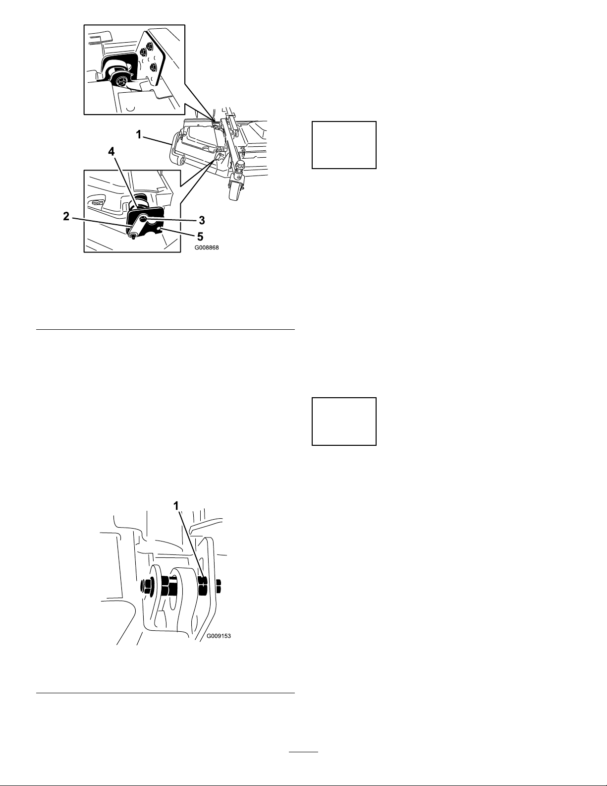
6.Adjusttheforwardeccentricuntilitjustmakes
contactwiththeinnerslotsurfaceofthe
winglet-pivotbrackets.
7.Tightentheboltandnutforthiseccentricto149
N·m(1 10ft-lb).
8.Repeattheprocedureontheoppositewinglet.
6
CheckingtheFluidLevels
NoPartsRequired
Figure7
1.Winglet4.Eccentric
2.Hingepin5.Upperhole
3.Stopbolt
3.Rotatetheforwardeccentricuntilitreaches
maximumclearancewiththeinner-slotsurface
ofthewinglet-pivotbracket.
4.Rotatetherear(closesttothetractionunit)
eccentricuntiltheoutsidebladetipisabout3
mm(1/8inch)higherthanthedesiredheightof
cut(Figure7).
Note:Thereisanotchontheeccentrichex,
whichis180°fromthelobeontheeccentric
cam(Figure8).Usethenotchestoreference
thelocationofthelobeswhenadjustingthe
eccentrics.
g008868
Procedure
1.Checktheengine-oillevelbeforestartingthe
engine;refertoCheckingtheEngine-OilLevel
(page71).
2.Checkthehydraulic-uidlevelbeforestarting
theengine;refertoCheckingtheHydraulicFluid
(page86).
3.Checkthecoolingsystembeforestartingthe
engine;refertoCheckingtheEngine-Cooling
System(page81).
7
GreasingtheMachine
NoPartsRequired
Procedure
Figure8
1.Eccentricnotch
5.Tightentheboltandnutforthiseccentricto149
N·m(1 10ft-lb).
Greasethemachinebeforeuse;refertoLubrication
(page66).Failuretoproperlygreasethemachine
resultsinprematurefailureofcriticalparts.
g009153
20
Page 21
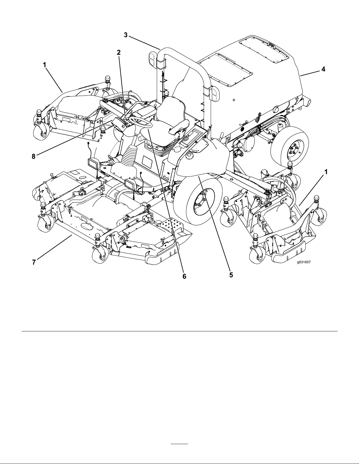
ProductOverview
Figure9
1.Wingmowerdeck5.Fueltank
2.Controlpanel6.Steeringwheel
3.Rollover-ProtectionSystem(ROPS)
4.Hood
7.Frontmowerdeck
8.InfoCenter
21
g031657
Page 22
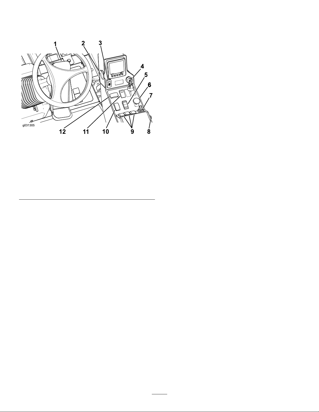
Controls
KeySwitch
Note:Determinetheleftandrightsidesofthe
machinefromthenormaloperatingposition.
Figure10
1.Tractionpedal
2.Lightswitch8.Hornbutton
3.Parking-brakeswitch
4.Keyswitch10.Throttleswitch
5.High—Lowrange-speed
switch
6.PTOswitch
7.Cruise-controlswitch
9.Deck-liftswitches
11.Hazardswitch
12.Turn-signalswitch
Thekeyswitchhas3positions:STOP,RUN/PREHEA T,
andSTART(Figure10).
High-LowRange-SpeedSwitch
PressthefrontoftheswitchtoselectHIGH-SPEED
RANGE.Presstherearoftheswitchtoselect
LOW-SPEEDRANGE.Themachinemustbestationary
ortravelingatlessthan1.0km/h(0.6mph)toshift
betweenHIGHandLOW(Figure10).
PTOSwitch
ThePTOswitchhas2positions:OUT(start)and
IN(stop).PulloutthePTObuttontoengagethe
implementormower-deckblades.Pushinthebutton
g031305
todisengagetheimplementoperation(Figure10).
Cruise-ControlSwitch
Thecruise-controlswitchsetsyourdesiredspeedof
themachine.
Movethecruise-controlswitchtothecenterposition
toturnthecruisecontroltotheONposition.Press
theswitchforwardtosetthespeed.Presstheswitch
rearwardtodisengagethecruisecontrol.(Figure10).
TractionPedal
Thetractionpedalcontrolstheforwardandreverse
operation.Pressthetopofthepedaltomovethe
machineforwardandthebottomtomoveitbackward.
Groundspeeddependsonhowfaryoupressthe
pedal.Formaximumgroundspeed,fullypressthe
pedalwhilethethrottleisintheHIGHIDLEposition
(Figure10).
Tostopthemachine,reduceyourfootpressureon
thetractionpedalandallowittoreturntothecenter
position.
LightSwitch
Pressthelightswitchupwardtoturnthelightstothe
ONposition(Figure10).
Pressthelightswitchdownwardtoturnthelightsto
theOFFposition.
Parking-BrakeSwitch
Theparking-brakeswitchrequires2actionstosetthe
brake.Whileholdingthesmalllatchback,pressthe
parking-brakeswitchforwardtoengagetheparking
brake.Presstheparking-brakeswitchrearwardto
disengagetheparkingbrake(Figure10).
Note:Footpedalmovementalsodisengagesthe
cruisecontrol.
Whenyouengagethecruisecontrol,youcan
changethecruise-controlspeed;refertoSettingthe
Cruise-ControlSpeed(page30).
HornButton
Pressthehornbuttontoactivatethehorn(Figure10).
Deck-LiftSwitches
Thedeck-liftswitchesraiseandlowerthemower
decks(Figure10).
Presstheswitchesforwardtolowerthemowerdeck
andrearwardtoraisethemowerdeck.
Note:Thedecksdonotlowerwhilethemachineis
intheHIGH-speedrange,andthedecksdonotraise
orlowerifyouareoutoftheseatwhiletheengineis
running.
Note:Thedeck-raisingfunctionislimitedatengine
speedsbelow2,000rpm.Only1deckraisesatatime
below2,000rpm.
22
Page 23

ThrottleSwitch
Thethrottleswitchhas2positions:LOWIDLEandHIGH
IDLE(Figure10).
Presstheswitchforwardfor2ormoresecondstoset
thethrottleatHIGHIDLE;presstheswitchrearward
for2ormoresecondstosetthethrottleatLOWIDLE;
ormomentarilypresstheswitchineitherdirectionto
increaseordecreasetheenginespeedin100-rpm
increments.
HazardSwitch
Pressthehazardswitchforwardtoengagethehazard
lightsandrearwardtodisengagethehazardlights
(Figure10).
Turn-SignalSwitch
CabControls
Model31699Only
Presstheleftsideoftheturn-signalswitchtoactivate
theleft-turnsignalandtherightsideoftheswitchto
activatetheright-turnsignal(Figure10).
Note:Thecenterpositionisoff.
PowerPoint
Youcaninsertyourportablechargerintothepower
pointtochargeapersonaldevice,suchasaphoneor
otherelectronicdevice(Figure11).
Figure11
1.Powerpoint
g032672
Figure12
1.Air-conditioningswitch4.Temperaturecontrol
2.Air-recirculationcontrol5.Windshield-wiperswitch
3.Fancontrol
Air-RecirculationControl
Setsthecabtoeitherrecirculatetheairinthecabinor
todrawairintothecabinfromoutside(Figure12).
6.Blankswitchesforoptional
kits
•Setittorecirculatetheairwhenusingthe
air-conditioning.
•Setittodrawairinwhenusingtheheaterorfan.
FanControl
Rotatethefancontrolknobtoregulatethespeedof
thefan(Figure12).
g033266
TemperatureControl
Rotatethetemperaturecontrolknobtoregulatethe
airtemperatureinthecab(Figure12).
AudibleAlarm(Console)
Thealarmisactivatedwhenafaultisdetected.
Thebuzzersoundswhenthefollowingoccur:
•Whentheenginesendsastopfault
•Whentheenginesendsacheck-enginefault
•Whenthefuellevelislow
Windshield-WiperSwitch
Usethisswitchtoturnthewindshieldwipersonor
off(Figure12).
AirConditioningSwitch
Usethisswitchtoturntheairconditioningonoroff
(Figure12).
WindShieldLatch
Liftuponlatchestoopenthewindshield(Figure13).
Pressinonlatchtolockwindshieldinopenposition.
23
Page 24
Pulloutanddownonlatchtocloseandsecurewind
11.3
1
2
3
4
5
6
8
9
G033320
7
shield.
Figure13
1.Windshieldlatch
RearWindowLatch
Liftuponlatchestoopentherearwindow.Pressin
onlatchtolockwindowinopenposition.Pulloutand
downonlatchtocloseandsecurewindow(Figure13).
InfoCenterControl
Start-UpScreen
Whenyoustartthemachine,thestart-upscreen
appears,displayingthecorrespondingiconsthat
apply(i.e.,theparkingbrakeisapplied,thePTOisin
theONposition,cruisecontrolisintheONposition).
Note:Thefollowinggureisanexamplescreen;this
screenismeanttoshowallofthepotentialiconsthat
couldappearonthescreenwhileoperating.
Refertothefollowinggraphicforalloftheicon
meanings(Figure14).
g008830
Important:Therearwindowmustbeclosed
beforeopeningthehoodordamagemayoccur.
Seat-AdjustingLever
Pulloutthelevertoslidetheseatforwardorrearward.
Seat-Back-AdjustingLever
Movethelevertoadjusttheseat-backangle.
Armrest-AdjustingKnob
Rotatetheknobtoadjusttheangleofthearmrest.
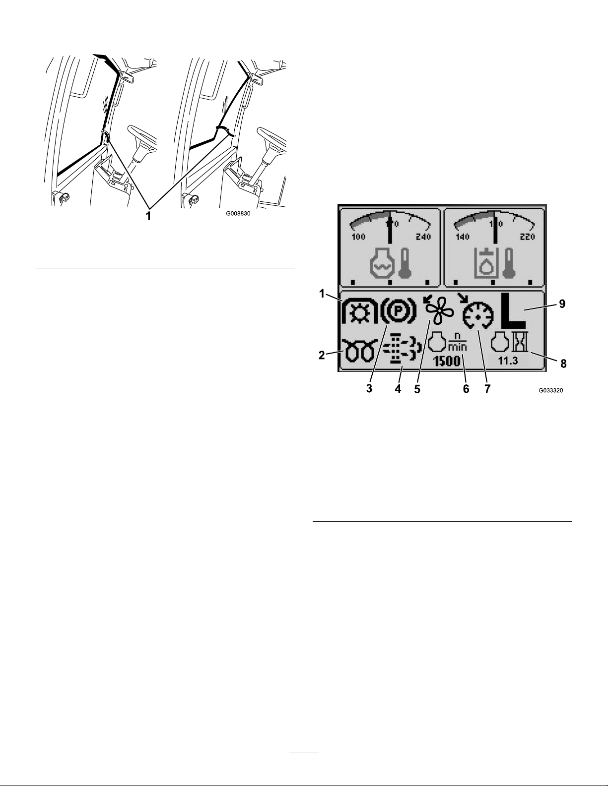
Figure14
1.PTOindicator
2.Glow-plugindicator7.Cruise-control-set
3.Parking-brakeindicator8.Engine-hoursindicator
4.Diesel-particulatelter
(DPF)maintenance
indicator
5.Fan-reverseindicator
ScreenFunctions
6.Enginespeed
indicator
9.H/L(High/Low)
transmission-range
indicator
Pressthecorrespondingbuttontoviewscreen1or
screen2,tostoptheaudiblealarm,toviewthefault
screen,ortoexit(Figure15).
g033320
24
Page 25
1
2
3 4
5
6
7
8
9 10
G033145
1
2
G033146
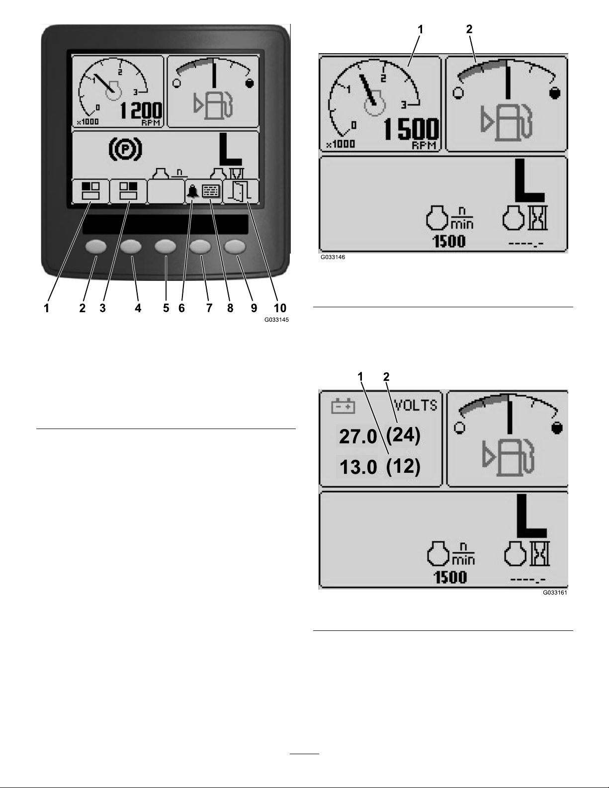
Figure16
27.0
(24)
13.0
(12)
2
1
1.Tachometer2.Fuel-levelindicator
g033146
Figure15
1.Screen1—top,leftscreen
2.Button17.Button4
3.Screen2—top,right
screen
4.Button29.Button5
5.Button310.Exit
Pressbuttons1to4toaccessthepop-up-menubar
onthebottomofthescreen(Figure15).
Afterthestart-upscreenappears,youcanselectwhat
youwouldlikedisplayedinboththetop,leftcorner
andtop,rightcornerofthedisplayscreenbypressing
button1orbutton2ontheInfoCentercontrol(Figure
15).
6.Audiblealarm
8.Faultscreen
Note:Whenyoushutoffthemachine,thetop2
screenswillremainattheprevioussettingbeforethe
machinewasshutoff.
Youcantogglebetweenthefollowingscreensby
pressingbutton1andbutton2:
•Tachometer—top,leftscreenFigure16
•Fuel-levelindicator—top,rightscreen(Figure16)
g033145
•12Vbattery-voltageindicator—top,leftscreen
(Figure17)
•24Vbattery-voltageindicator—top,left
screen(Figure17)
g033161
Figure17
•Hydraulic-uid-temperatureandfanindicator—top,
rightscreen(Figure18)
Note:InexampleFigure18,the
hydraulic-uid-coolingfansarerunningat
25%speedintheforwarddirection.
•Engine-coolant-temperatureandfan
indicator—top,leftscreen(Figure18)
25
Page 26
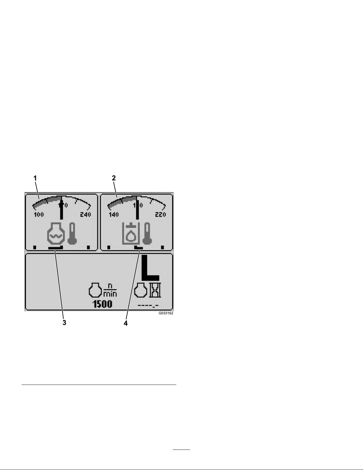
Note:InexampleFigure18,theengine-coolant
1
2
G033162
3
4
fansarerunningat50%speedinthereverse
direction.
Thisdisplayindicates(Figure14)fanspeedand
direction.Thefanspeediscontrolledbythe
hydraulic-uidtemperatureortheengine-coolant
temperature,andautomaticallyreversesas
needed.Areversecycleautomaticallyinitiatesto
helpblowdebrisofftherespectivehoodscreen,
wheneitherthetemperatureoftheenginecoolant
orthehydraulicuidreachesacertainpoint.
Additionally,theradiatorfansperformareverse
cycleevery21minutesregardlessofthecoolant
temperature.
Fandirectionisalsoindicatedonthe
engine-coolant-temperaturescreenandthe
hydraulic-uid-temperaturescreen.Ifthebaris
totherightofthemidpointhashmark,thefans
arerunningintheforwarddirection.Ifthebaristo
theleftofthemidpointhashmark,thefansare
runninginthereversedirection(Figure18).
Pressthearrowkeystonavigatethefaultscreen.
Pressanykeytorevealtheinformationkeysonthe
screen.
Diesel-Particulate-Filter(DPF)MaintenanceIndicator
Ifthediesel-particulate-lter(DPF)maintenance
indicator(Figure14)appearsonthescreen,
immediatelycontactyourTorodistributorforservice;
refertoDieselParticulateFilterRegeneration(page
48).
Fuel-LevelIndicator
Thisdisplayindicatestheleveloffuelinthetank
(Figure16).
PTOIndicator
Thisdisplayindicates(Figure14)whenthePTOis
engaged.
Parking-BrakeIndicator
Thisdisplayindicatesthattheparkingbrakeis
engaged(Figure14).
Cruise-ControlIndicator
Thisdisplay(Figure14)indicateswhenthecruise
controlisset.
H/L(High/LowRange)Speed-RangeIndicator
Thisdisplayindicatestheselectedtransmission
speedrange(Figure14).
Glow-PlugIndicator
Thisdisplayindicateswhentheengineispreheating
(Figure14).
Engine-HoursIndicator
Thisdisplayshowsthetotalhoursthattheenginehas
1.Engine-coolant-temperature
indicator
2.Hydraulic-uid-temperature
indicator
g033162
Figure18
3.Engine-coolantfans
runningat50%speedin
thereversedirection
4.Hydraulic-uid-cooling
fansrunningat25%speed
intheforwarddirection
beenoperated(Figure14).
Tachometer
Thisdisplayshowstheengine-operatingspeedinrpm
(Figure16).
Hydraulic-Fluid-TemperatureIndicatorand
Cooling-Fan-StatusIndicator
Ifafaultappearsonthescreen,pressanykeytoview
theactivefaultadvisory(Figure15).
Note:Contactyoursupervisorormechanictorelay
thefaultadvisoryanddeterminethecourseofaction.
Thisdisplayindicatesthehydraulic-uidtemperature
andthestatusofthecoolingfan(Figure18).
Engine-Coolant-TemperatureIndicatorand
Cooling-Fan-StatusIndicator
Thisdisplayindicatestheengine-coolanttemperature
andthestatusofthecoolingfan(Figure18).
26
Page 27
BatteryVoltage
MainMenu
Thisdisplayshowsboththe12Vand24Vbattery
voltage(Figure17).
Service-DueIndicator
Thisdisplayindicatesthetimeuntilthenextregular
serviceinterval.
Note:Afteryouservicethemachine,resetthe
indicator.
1.Pressandholdthefar,rightbuttononthe
InfoCenter.
Note:TheMainMenuscreenappears.
2.SelectServiceusingthe2buttonsonthe
left;pressthebuttonbelowtherightarrowto
continue.
3.SelectHoursandpressthebuttonbelowthe
rightarrow.
4.PressthebuttonbelowResetHours.
5.SelecttheHoursfortheappropriatenextservice
timeandpressthebuttonbelowtherightarrow.
Note:Acheckmarkappearsoncetheindicator
hasbeenreset.
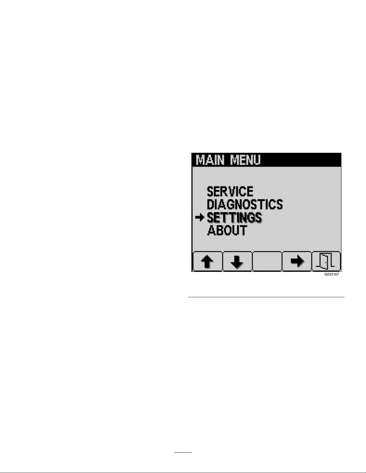
Pressandholdthefthbutton(farright)onthe
InfoCentertoaccessthemainmenu.
Fromthemainmenuscreen,youcanaccessthe
Servicescreen,Diagnosticsscreen,Settingsscreen,
ortheAboutscreen(Figure19).
ServiceScreen
IfyouhaveanissuethatrequiresuseoftheService
screen(i.e.,calibratingthetractionpedal),contact
yourAuthorizedToroServiceDealerforassistance.
InfoCenterPINEntry
1.Fromthestart-upscreen,pressandholdbutton
5untiltheMainMenuappears(Figure19).
6.Whenyouarenished,pressthebuttonbelow
theexiticon(pictureofanopendoor)toreturn
tothemainscreen,orpresscanceltoexit.
AudibleAlarm(InfoCenter)
Thealarmsoundsduringthefollowingscenarios:
Loweringthedeck
•Theengineisnotrunning
•Anydeckisbeinglowered
Deckisoutofoat
•ThePTOisrequestedandqualied
•Anydeckisbelowthelimit,butnotoating
MachinesendsarequesttotheInfoCenter
•Theenginesendsared,stoplampmessage
Note:Ifthealarmstopsoriftheoperator
acknowledgesthealarmbypressinganybutton
ontheInfoCenter,thenthealarmshouldstop.
•Regenerationrequestedbytheengine
g033167
Figure19
2.Pressbutton2untilyoureachSettingsonthe
MainMenuscreenandpressbutton4toselect
Settings(Figure19).
3.FromtheSettingsscreen,pressbutton4to
selectDisplay(Figure20).
•Anyenginefault
•Anyadvisory;refertoInfoCenterAdvisories(page
31)
•Theenginesendsanamber-warningmessage
•Thefuellevelisbelow2.2%
27
Page 28
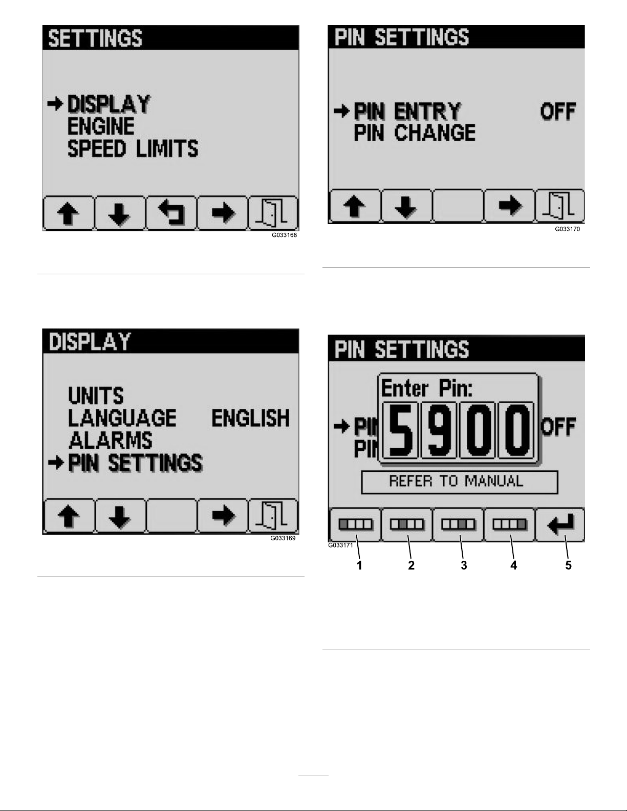
Figure20
1
2
3
4
5
G033171
g033168
Figure22
g033170
4.Pressbutton2untilyoureachPINSettingson
theDisplayscreenandpressbutton4toselect
PINSettings(Figure21).
Figure21
5.FromthePINSettingscreen,pressbutton4to
selectPINEntry(Figure22).
6.EnterthedefaultPIN,5900,intotheEnterPIN
screenbyusingbuttons1to4toselectthe
digitsandpressbutton5tocompletethePIN
(Figure23).
g033169
g033171
Figure23
1.Digit14.Digit4
2.Digit25.EnterPIN
3.Digit3
28
Page 29

ChangingtheInfoCenterPIN
1 2 3
4
5
1 2 3
4
5
1 2 3
4
5
1.Fromthestart-upscreen,pressandholdbutton
5untiltheMainMenuappears(Figure19).
2.Pressbutton2untilyoureachSettingsonthe
MainMenuscreenandpressbutton4toselect
Settings(Figure19).
3.FromtheSettingsscreen,pressbutton4to
selectDisplay(Figure20).
4.Pressbutton2untilyoureachPINSettingson
theDisplayscreenandpressbutton4toselect
PINSettings(Figure21).
5.Pressbutton2untilyoureachPINChangeon
thePINSettingsscreenandpressbutton4to
selectPINChange(Figure22).
6.EnteryouroldPINusingbuttons1to4andpress
button5whenyoucompletethePIN(Figure24).
Note:ThedefaultPINwhenyouinitiallysetup
yourPINis5900.
g033173
Figure25
1.Digit14.Digit4
2.Digit25.EnterPIN
3.Digit3
Figure24
1.Digit14.Digit4
2.Digit25.EnterPIN
3.Digit3
7.EnteryournewPINusingbuttons1to4and
pressbutton5whenyoucompleteyournew
PIN(Figure25).
8.ConrmyournewPINusingbuttons1to4and
pressbutton5whenyoucompletethePIN
(Figure26).
g033172
g033174
Figure26
1.Digit14.Digit4
2.Digit25.EnterPIN
3.Digit3
29
Page 30
ChangingtheInfoCenterDisplay
1 2 3
4
5
1
G033179
1
+
2 3
G033180
Brightness/Contrast
1.Fromthestart-upscreen,pressbutton5to
accessthebrightness/contrastpop-up-menu
bar(Figure27).
g033179
Figure28
1.Cruise-controlselection
Figure27
1.Decreasebrightness4.Increasecontrast
2.Increasebrightness5.Exit
3.Decreasecontrast
2.Pressbutton1todecreasebrightness,button
2toincreasebrightness,button3todecrease
contrast,andbutton4toincreasecontrast
(Figure27).
3.Whenyouhavesetyourbrightness/contrast,
pressbutton5toexit(Figure27).
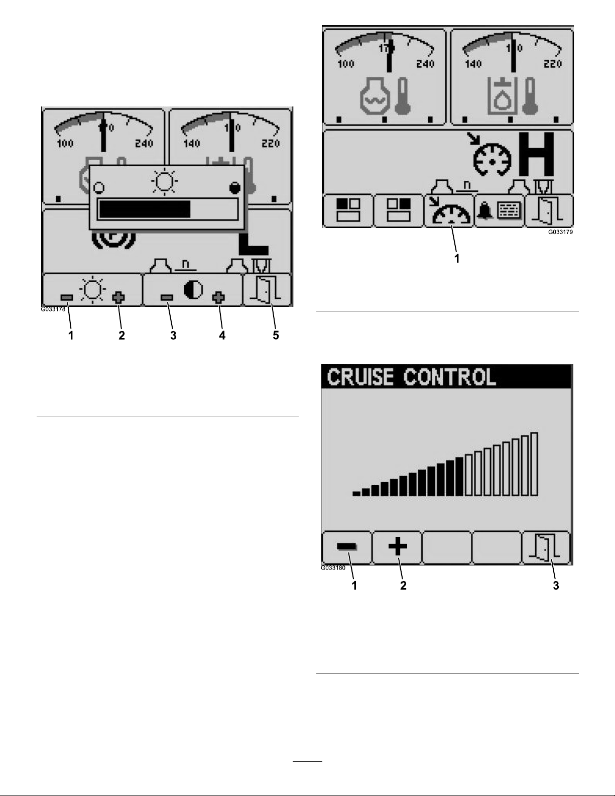
SettingtheCruise-ControlSpeed
Youcansetthecruise-controlspeedbymovingthe
cruise-controlswitchmomentarilyforward,viathe
Infocenterasfollows:
1.Movethecruise-controlswitchtotheONposition
(Figure10).
2.Whenthecruise-controliconappearsonthe
displayscreen,pressbutton1to4toaccessthe
pop-up-menubar.
3.Pressbutton3toaccesstheCruiseControl
screen(Figure28)˙.
4.FromtheCruiseControlscreen,pressbutton1
g033178
todecreasethecruise-controlspeedorbutton2
toincreasethecruise-controlspeed(Figure29).
Figure29
1.Decreasecruise-control
speed
2.Increasecruise-control
speed
3.Exit
g033180
5.Whenyouhavesetyourdesiredcruise-control
speed,pressbutton5toexit(Figure29).
30
Page 31

InfoCenterAdvisories
1
2
3
OperatoradvisoriesautomaticallydisplayontheInfoCenterscreenwhenamachinefunctionrequiresadditional
action.Forexample,ifyouattempttostarttheenginewhilepressingthetractionpedal,anadvisorydisplays,
indicatingthatthetractionpedalmustbeintheNEUTRALposition.
Foreachadvisorythatoccurs,thereisacondition(e.g.,startdenied,PTOdenied,cruisecontroldenied),
anadvisorycode(number),aqualier(thecauseoftheadvisorydisplayed),andadisplaytext(whatthe
advisorydisplaysastextonthescreen)asshowninFigure30.
Figure30
g031999
1.Displaytext
2.Code
3.PressanykeyontheInfoCentertoclearthetextfromthe
displayscreen.
Note:Advisoriesdonotlogintothefaultlog.
Note:Y oucanclearanadvisoryfromthedisplayscreenbypressinganyoftheInfoCenterkeys.
RefertothefollowingtableforalltheInfoCenteradvisories:
ConditionCodeQualier
StartDenied
StartDenied
StartDenied
StartDenied
StartDenied
StartDenied
PTODenied
PTODenied
PTODenied
PTODenied
PTODenied
4Teachengaged
5
6NotinNEUTRALT ostart,movetractionpedalto
7
8DeckswitchengagedT ostart,disengagedeckswitch
9Recyclepower
102
106
107
108Enginehot
109
PTOengagedTostart,disengagePTO
Neitherinseatnorparking
brakeapplied
Inhighrange(onlycutinlow)ToengagePTO,mustbeinlow
OutofseatToengagePTO,operatormust
Nodecksoating(hitadown
key)
LossofCANbus(service
required)
DisplayText
N/A
NEUTRAL
Tostart,mustbeseatedorset
parkingbrake
Tostart,turnkeyswitchoff,
thenon
range
beseated
ToengagePTO,lowerdecks
ToengagePTO,letenginecool
ToengagePTO,requires
service
31
Page 32

PTODenied
CruiseControlDenied
DeckLowerDenied302
DeckLowerDenied303
DeckLowerDenied304
DeckNotFloating(onengine
start)
RangeHiDenied502
RangeHiDenied503
RangeHiDenied504Rightdecknotup
RangeHiDenied505
RangeHiDenied506
RangeHiDenied507
RangeHiDenied508
RangeHiDenied509
RangeHiDenied510
RangeHiDenied51 1
RangeHiDenied512HydraulicoiltoocoldT osethighrange,lethydraulic
RangeLoDenied602
RangeLoDenied603
RangeLoDenied604
TractionDisabled804
TractionDisabled805NotinNEUTRALFortraction,movetraction
TractionDisabled806
EngineAdvisory1205
EngineAdvisory1206
EngineAdvisory1207
EngineAdvisory1208
EngineAdvisory1209DPFservicerequiredRegenerationrequiredwithin
110Hydraulicoiltoocold
202Tooslowtocapturecruise
control
Can’tlowerintransport
Outofseat
Servicerequired
402Adviseoperatortopressdown
switches
LeftdecknotupTosethighrange,liftleftdeck
CenterdecknotupT osethighrange,liftcenter
LeftdeckoatingTosethighrange,liftleftdeck
CenterdeckoatingT osethighrange,liftcenter
RightdeckoatingTosethighrange,liftrightdeck
PTOswitchengaged
Cruisecontrolengaged
Speedtoohigh
LossofCANbus(service
required)
Cruisecontrolengaged
Speedtoohigh
LossofCANbus(service
required)
ParkingbrakeON
Outofseat
Starterhasbeenactivefor30
seconds
ReplaceengineairlterChecktheairlter
Servicedue
Servicepastdue
ToengagePTO,lethydraulic
oilwarmup
Increasegroundspeed
Tolowerdeck,returntraction
pedaltoNEUTRAL
Tolowerdeck,operatormust
beseated
Tolowerdeck,requiresservice
Tooat,lowerdecks
deck
Tosethighrange,liftrightdeck
fully
deckfully
fully
Tosethighrange,disengage
PTO
Tosethighrange,disengage
cruise
Tosethighrange,reduce
groundspeed
Tosethighrange,requires
service
oilwarmup
Tosetlowrange,disengage
cruise
Tosetlowrange,reduce
groundspeed
Tosetlowrange,requires
service
Fortraction,releaseparking
brake
pedaltoNEUTRAL
Fortraction,operatormustbe
seated
Engine30secondstartertime
out
Engineservicedue
approaching
Engineservicepastdue
30minutes
32
Page 33

EngineAdvisory1210Enginederateduetohigh
Letenginecool
temperature
EngineAdvisory1211Enginespeedrestricted:
hydraulicoiltoocold
Hydraulicoilislessthan4°C
(40°F),soderatetheengine
speedto1,650rpm
FuelLevel1302Fuellevelislow
TPNotCalibrated
1402
Tractionpedalisoutof
Addfuel
Calibratethetractionpedal
calibration
Teach1500EnteredteachmodeEnteredtractionpedal
teach—pleasewait
Teach1502
TractionpedalisoutofNEUTRAL
Returntractionpedalto
NEUTRAL
Teach1503
Teach1504
Teach1505
Slowlymovethetractionpedal
forward
Slowlymovethetractionpedal
forward
NeutralforwardcapturepassedNeutralforwardcapturepassed
Neutralforwardcapture
failed—toofast
Neutralforwardcapture
failed—movementtoofast;try
again
Teach1506
Neutralforwardcapturefailed
Restartteachmode
(outofrange)—voltage
capturedwasoutof
specication
Teach1507MovetractionpedaltoMAX
FORWARDandhold
Teach1508
Teach1509
MaxforwardcapturepassedMaxforwardcapturepassed
Maxforwardcapturefailed(out
MovetractionpedaltoMAX
FORWARDandhold
Restartteachmode
ofrange)—voltagecaptured
wasoutofspecication
Teach1510
Slowlymovethetractionpedal
inREVERSE
Slowlymovethetractionpedal
inREVERSE
Teach1511NeutralrevcapturepassedNeutralrevcapturepassed
Teach1512
Neutralrevcapturefailed—too
fast
Neutralrevcapture
failed—movementtoofast;
tryagain
Teach1513
Neutralrevcapturefailed(out
Restartteachmode
ofrange)—voltagecaptured
wasoutofspecication
Teach1514MovetractionpedaltoMAX
REVERSEandhold
MovetractionpedaltoMAX
REVERSEandhold
Teach1515MaxreversecapturepassedMaxreversecapturepassed
Teach1516
Maxreversecapturefailed(out
Restartteachmode
ofrange)—voltagecaptured
wasoutofspecication
Teach1517
Teach1518
DeckRaiseDenied1602
TPteachdone/valuesstored
TPteachwasunsuccessful
OutofseatOperatormustbeseated
DeckRaiseDenied1603Parkingbrakenotset
Exitteach
Exitteachandtryagain
Setparkingbrake
DeckRaiseDenied1604NotinNEUTRALReturntractionpedalto
NEUTRAL
33
Page 34

DeckRaiseDenied1605
DeckRaiseDenied1606AlldecknotraisingtogetherIncreasetheenginespeed
ServicerequiredContractyourT orodistributor
to2,000rpm,andthedecks
willraiseoneatatimewhen
all3switchesarehelddown
simultaneously
Specications
Note:Specicationsanddesignaresubjecttochangewithoutnotice.
Widthofcut
Overall488cm(192inches)
Frontmowerdeck
Wingmowerdeck
Frontandone-wingmowerdeck
Overallwidth
Mowerdecksdown
Mowerdecksup(transport)251cm(99inches)
Overallheight(withwingmowerdecksdown)
WithROPS216cm(85inches)
WithoutROPS160cm(63inches)
Withcab
Overalllength442cm(174inches)
Minimumgroundclearance(atthemachinecenterline)26.2cm(10.3inches)
Wheeltread(tothecenterofthetire)
Front
Rear
Wheeltread(totheoutsideofthetire)
Front
Rear
Wheelbase
NetWeight(withmowerdecks)
Withoutcab
Withcab
234cm(92inches)
145cm(57inches)
361cm(142inches)
505cm(199inches)
240cm(94.5inches)
158.8cm(62.5inches)
142cm(56inches)
190.5cm(75inches)
170cm(67inches)
194cm(76.5inches)
2,935kg(6,470lb)
3,202kg(7,060lb)
Attachments/Accessories
AselectionofToroapprovedattachmentsand
accessoriesisavailableforusewiththemachineto
enhanceandexpanditscapabilities.Contactyour
AuthorizedServiceDealerorDistributororgoto
www.T oro.comforalistofallapprovedattachments
andaccessories.
Tobestprotectyourinvestmentandmaintainoptimal
performanceofyourToroequipment,countonT oro
genuineparts.Whenitcomestoreliability,T oro
deliversreplacementpartsdesignedtotheexact
engineeringspecicationofourequipment.Forpeace
ofmind,insistonTorogenuineparts.
34
Page 35

Operation
FuelSafety
Note:Determinetheleftandrightsidesofthe
machinefromthenormaloperatingposition.
BeforeOperation
BeforeOperationSafety
GeneralSafety
•Neverallowchildrenoruntrainedpeopleto
operateorservicethemachine.Localregulations
mayrestricttheageoftheoperator.Theowner
isresponsiblefortrainingalloperatorsand
mechanics.
•Becomefamiliarwiththesafeoperationofthe
equipment,operatorcontrols,andsafetysigns.
Knowhowtostopthemachineandenginequickly.
•Checkthatallsafetydevicesareattachedand
functioningproperly.Thisincludes,butisnot
limitedto,operator-presencecontrols;safety
switchesandshields;therolloverprotection
system(ROPS);attachments;andbrakes.Do
notoperatethemachineunlessallsafetydevices
areinpositionandfunctioningasintendedbythe
manufacturer.
•Alwaysinspectthemachinetoensurethatthe
blades,bladebolts,andcuttingassemblyarenot
wornordamaged.Replacewornordamaged
bladesandboltsinsetstopreservebalance.
•Inspecttheareawhereyouwillusethemachine
andremoveallobjectsthatthemachinecould
potentiallythrow.
•Evaluatetheterraintodeterminetheappropriate
equipmentandanyattachmentsoraccessories
requiredtooperatethemachineproperlyand
safely.
DANGER
Incertainconditions,fuelisextremely
ammableandhighlyexplosive.Areor
explosionfromfuelcanburnyouandothers
andcandamageproperty.
•Fillthefueltankoutdoors,inanopenarea,
whentheengineiscold.Wipeupanyfuel
thatspills.
•Neverllthefueltankinsideanenclosed
trailer.
•Neversmokewhenhandlingfuel,andstay
awayfromanopenameorwherefuel
fumesmaybeignitedbyaspark.
•Storefuelinanapprovedcontainerand
keepitoutofthereachofchildren.Never
buymorethana180-daysupplyoffuel.
•Donotoperatethemachinewithoutthe
entireexhaustsysteminplaceandin
properworkingcondition.
WARNING
Fuelisharmfulorfatalifswallowed.
Long-termexposuretovaporscancause
seriousinjuryandillness.
•Avoidprolongedbreathingofvapors.
•Keepyourhandsandfaceawayfromthe
nozzleandthefuel-tankopening.
•Keepfuelawayfromyoureyesandskin.
•Useonlyanapprovedfuelcontainer.
•Neverremovethefuelcaporaddfueltothefuel
tankwhiletheengineisrunning.
•Neverllcontainersinsideavehicleoronatruck
ortrailerbedwithaplasticliner.Alwaysplace
containersonthegroundandawayfromyour
vehiclebeforelling.
•Removetheequipmentfromthetruckortrailer
andaddfueltoitwhileitisontheground.Ifthis
isnotpossible,thenaddfuelusingaportable
containerratherthanfromafuel-dispensernozzle.
•Keepthefuel-dispensernozzleincontactwith
therimofthefueltankorcontaineropeningat
alltimesuntilfuelingiscomplete.Donotusea
nozzlelock-opendevice.
•Ifyouspillfuelonyourclothing,changeyour
clothingimmediately.
•Fillthefueltankuntilthefuellevelis25mm(1
inch)belowthebottomofthellerneck.Donot
35
Page 36

overllthefueltank.Replacethefuel-tankcap
andtightenitsecurely.
CheckingtheEngine-Oil Level
Beforeyoustarttheengineandusethemachine,
checktheoillevelintheenginecrankcase;referto
CheckingtheEngine-OilLevel(page71).
CheckingtheCooling Systems
Beforeyoustarttheengineandusethemachine,
checkthecoolingsystems;refertoCheckingthe
Engine-CoolingSystem(page81)andCleaningthe
CoolingSystems(page82).
CheckingtheHydraulic System
Beforeyoustarttheengineandusethemachine,
checkthehydraulicsystem;refertoCheckingthe
HydraulicFluid(page86).
FuelTable
Dieselfuelspecication
ASTMD975
No.1-DS15
No.2-DS15
EN590EuropeanUnion
ISO8217DMX
JISK2204GradeNo.2
KSM-2610
Location
USA
International
Japan
Korea
•Useonlyclean,freshdieselfuelorbiodieselfuels.
•Purchasefuelinquantitiesthatcanbeusedwithin
180daystoensurefuelfreshness.
Usesummer-gradedieselfuel(No.2-D)at
temperaturesabove-7°C(20°F)andwinter-grade
fuel(No.1-DorNo.1-D/2-Dblend)belowthat
temperature.
Note:Useofwinter-gradefuelatlowertemperatures
provideslowerashpointandcoldowcharacteristics
whicheasesstartingandreducesfuellterplugging.
Usingsummer-gradefuelabove-7°C(20°F)
contributestowardlongerfuelpumplifeandincreased
powercomparedtowinter-gradefuel.
FillingtheFuelTank
FuelTankCapacity
132L(35USgallons)
FuelSpecication
Important:Useonlyultra-lowsulphurdiesel
fuel.Fuelwithhigherratesofsulfurdegrades
thedieseloxidationcatalyst(DOC),whichcauses
operationalproblemsandshortenstheservicelife
ofenginecomponents.
Failuretoobservethefollowingcautionsmay
damagetheengine.
•Neverusekeroseneorgasolineinsteadofdiesel
fuel.
•Nevermixkeroseneorusedengineoilwiththe
dieselfuel.
•Neverkeepfuelincontainerswithzincplatingon
theinside.
•Donotusefueladditives.
PetroleumDiesel
Biodiesel
Thismachinecanalsouseabiodieselblendedfuelof
uptoB20(20%biodiesel,80%petroleumdiesel).
Sulfurcontent:Ultra-lowsulfur(<15ppm)
Biodieselfuelspecication:ASTMD6751or
EN14214
Blendedfuelspecication:ASTMD975,EN590,
orJISK2204
Important:Thepetroleumdieselportionmust
beultra-lowsulfur.
Observethefollowingprecautions:
•Biodieselblendsmaydamagepaintedsurfaces.
•UseB5(biodieselcontentof5%)orlesserblends
incoldweather.
•Monitorseals,hoses,gasketsincontactwithfuel
astheymaybedegradedovertime.
•Fuellterpluggingmaybeexpectedforatime
afterconvertingtobiodieselblends.
•ContactyourAuthorizedT oroDistributorifyou
wishformoreinformationonbiodiesel.
Cetanerating:45orhigher
Sulfurcontent:Ultra-lowsulfur(<15ppm)
36
Page 37

AddingFuel
1.Parkthemachineonalevelsurface(Figure31).
2.Shutofftheengineandengagetheparking
brake.
3.Cleanaroundthefuel-tankcapandremovethe
cap.
4.Addfuelandinstallthefuel-tankcap.Wipeup
anyspilledfuel.
CheckingtheTirePressure
ServiceInterval:Beforeeachuseordaily
Thecorrectairpressureinthefronttiresis220kPa
(32psi)andthereartiresis207kPa(30psi)as
showninFigure32.
Important:Maintainpressureinalltiresto
ensureagoodqualityofcutandpropermachine
performance.Donotunderinatethetires.
Checktheairpressureinallthetiresbefore
operatingthemachine.
Tractionperformance,includingtire-slipcontrol,
isdependentontheratioofthetiresizebetween
thefrontandreartires.OnlyusegenuineToro
tires.
Figure31
g001055
Figure32
CheckingtheCasterWheel TirePressure
Thecorrectairpressureinthecasterwheeltiresis
340kPa(50psi).
Important:Maintainpressureinalltiresto
ensureagoodqualityofcutandpropermachine
performance.Donotunderinatethetires.
Checktheairpressureinallthetiresbefore
g031226
operatingthemachine.
37
Page 38

CheckingtheTorqueofthe Wheel-LugNuts
ServiceInterval:Aftertherst10hours
Every250hours
WARNING
Failuretomaintainthepropertorqueofthe
wheelnutscouldresultinfailureorlossofa
wheel,andmayresultinpersonalinjury.
Torquethefrontandrear-wheelnutsto135
to150N·m(100to110ft-lb)after10hoursof
operation.Torquethenutsevery250hours
thereafter.
AdjustingtheHeightofCut
Youcanadjusttheheightofcutfrom25to153mm(1
to6inches)in13mm(1/2inch)increments.Toadjust
theheightofcut,positionthecaster-wheelaxlesin
theupperorlowerholesofthecasterforks,addor
removeanequalnumberofspacersfromthecaster
forks,andadjusttherearchain(frontdeckonly)tothe
desiredholes.
AdjustingtheFrontMowerDeck
1.Starttheengineandraisethemowerdecksso
youcanchangetheheightofcut.
Figure33
1.Casterwheelheight-of-cut
mountingholes
4.Usingthesuppliedcaster-capwrench,loosen
thetensioningcapandremoveitfromthe
caster-spindleshaftandslidethecastershaft
outofthecasterarm(Figure34).
2.Casterforkheight-of-cut
spacers
g031660
2.Shutofftheengineandremovethekeyafterthe
mowerdeckisraised.
3.Positionthecaster-wheelaxlesinthesame
holesinallofthecasterforks;refertothechart
(Figure33)todeterminethecorrectholesfor
thesetting.
Note:Topreventgrassbuildupbetweenthe
wheelandthefork,operatethemachineatthe
76mm(3inches)heightofcutorhigherand
installtheaxleboltinthebottomcaster-fork
hole.Whenoperatingthemachineataheight
ofcutlowerthan76mm(3inches)andwhen
youdetectgrassbuildup,reversethedirection
ofthemachinetopullanyclippingsawayfrom
thewheelandfork.
g031661
Figure34
1.Tensioningcap4.T opaxle-mountinghole
2.Spacers(6)5.Casterwheel
3.Shims(2topand2bottom)
5.Slidetheappropriatenumberofspacersonto
theshafttogetthedesiredheightofcut.
Note:Refertothecharttodeterminethe
combinationsofspacersforthesetting(Figure
33).
Note:Y oumayusetheshimsinany
combinationaboveorbelowthecaster-armhub
(asrequired)toachievethedesiredheightof
cutordecklevel.
6.Pushthecastershaftthroughthefrontcaster
arm.
7.Installtheshims(asoriginallyinstalled)andthe
remainingspacersontotheshaft(Figure34).
38
Page 39

8.Installthetensioningcapandtightenitwith
thesuppliedcaster-capwrenchtosecurethe
assembly(Figure34).
9.Removethehairpincotterandclevispin
securingtheheight-of-cutchainstotherearof
themowerdeck(Figure35).
AdjustingtheWingMowerDecks
1.Starttheengineandraisethemowerdecksso
youcanchangetheheightofcut.
2.Shutofftheengineandremovethekeyafter
youraisethemowerdeck.
3.Positionthecaster-wheelaxlesinthesame
holesinallofthecasterforks;refertothe
charttodeterminethecorrectholesforthe
height-of-cutsetting(Figure37).
Note:Topreventgrassbuildupbetweenthe
wheelandthefork,operatethemachineatthe
76mm(3inches)heightofcutorhigherand
installtheaxleboltinthebottomcaster-fork
hole.Whenoperatingthemachineataheight
ofcutlowerthan76mm(3inches)andwhen
youdetectgrassbuildup,reversethedirection
ofthemachinetopullanyclippingsawayfrom
thewheelandfork.
Figure35
1.Height-of-cutchain
2.Clevispin
3.Hairpincotter
10.Mounttheheight-of-cutchainstothedesired
height-of-cutholewiththeclevispinandhairpin
cotter(Figure36).
Note:Whenmowingataheightofcutbelow51
mm(2inches),movetheskids,gagewheels,
androllerstothehighestholes.
g008979
Figure37
g031395
4.Usingthesuppliedcaster-capwrench,loosen
thetensioningcapandremoveitfromthe
caster-spindleshaftandslidethecastershaft
outofthecasterarm(Figure38).
Note:Youmayuseshimsinanycombination
aboveorbelowthecasterarmhubasrequired
toachievethedesiredheightofcutordecklevel.
Figure36
decal131-6025
39
Page 40

Figure38
1.Tensioningcap4.T opaxle-mountinghole
2.Spacers(6)5.Casterwheel
3.Shims(2topand2bottom)
5.5.Install2shimsontotheshaftasoriginally
installedandslidetheappropriatenumberof
spacersontotheshafttogetthedesiredheight
ofcut.
6.Pushthecastershaftthroughthecasterarm.
7.Installtheshims(asoriginallyinstalled)andthe
remainingspacersontotheshaft.
8.Installthetensioningcapandtightenitwith
thesuppliedcaster-capwrenchtosecurethe
assembly.
AdjustingtheSkids
AdjustingtheInnerSkids
g031661
g032003
Figure39
Mounttheinnerskidsinthelowerpositionwhen
operatingatheightsofcutgreaterthan51mm(2
inches)andinthehigherpositionwhenoperatingat
heightsofcutlowerthan51mm(2inches).
Adjusttheinnerskids(Figure39).
Important:Torquethescrewatthefrontofeach
innerskidto9to11N·m(80to100in-lb).
40
Page 41
AdjustingtheOuterSkids
AdjustingtheMowerDeck
Mounttheouterskidsinthelowerpositionwhen
operatingatheightsofcutgreaterthan51mm(2
inches)andinthehigherpositionwhenoperatingat
heightsofcutlowerthan51mm(2inches).
Note:Whentheouterskidsbecomeworn,youcan
switchthemtotheoppositesidesofthemowerby
ippingthemover.Thisallowsyoutousetheouter
skidslongerbeforereplacingthem.
Adjusttheouterskids(Figure40).
Important:Torquethescrewatthefrontofeach
outerskidto9to11N·m(80to100in-lb).
Anti-ScalpRollers
Mounttherollerinthelowerpositionwhenoperating
atheightsofcutgreaterthan51mm(2inches)and
inahigherpositionwhenoperatingatheightsofcut
lowerthan51mm(2inches).
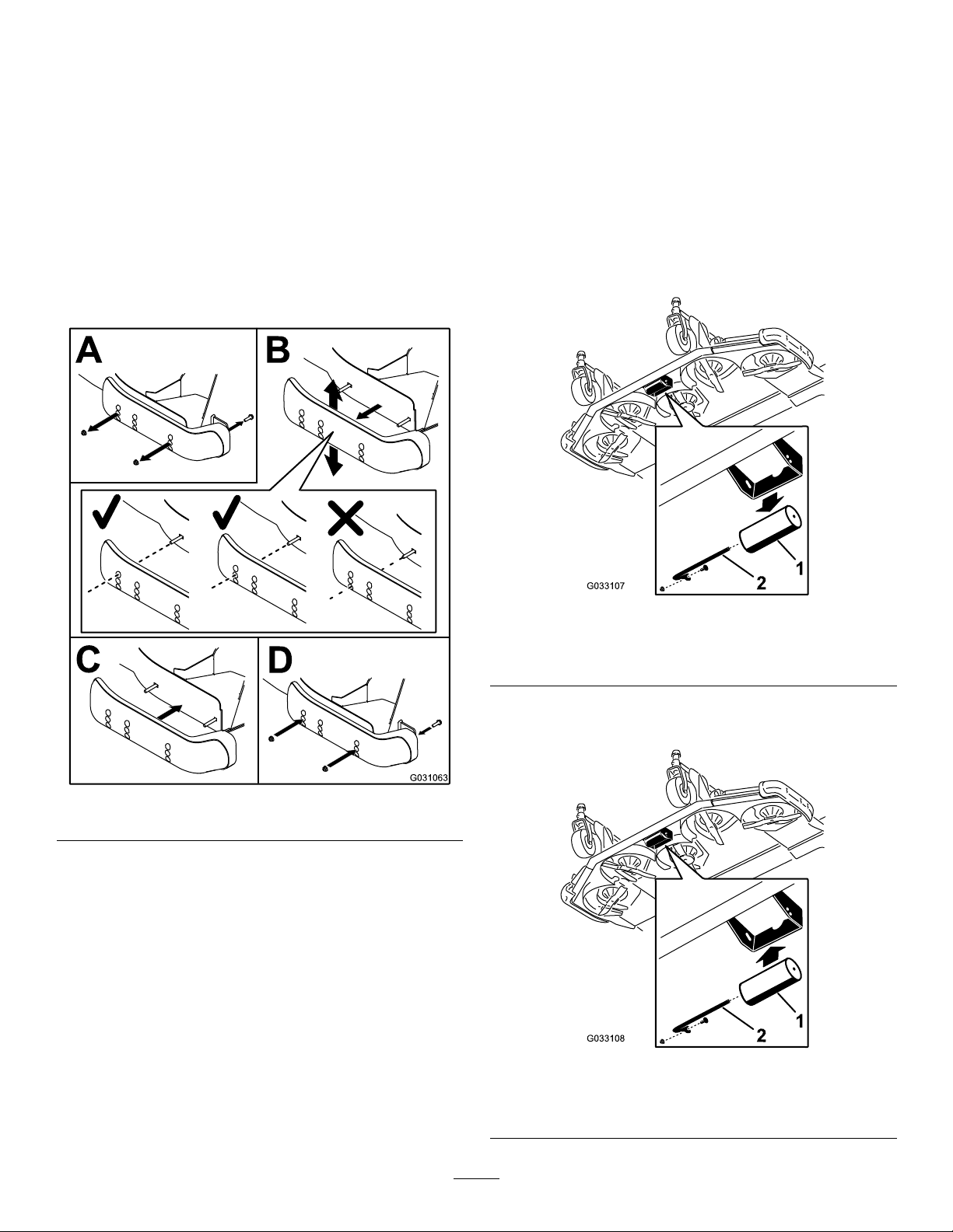
AdjustingtheRoller
1.Removetherollershaft,screw,andnutsecuring
therollertothedeckbracket(Figure41).
Figure40
g033107
Figure41
1.Roller
2.Rollershaft,screw,and
nut
2.Aligntherollerwiththetopholesandinstallthe
shaftwiththescrewandnut(Figure42).
g031063
g033108
Figure42
1.Roller
41
2.Rollershaft,screw,and
nut
Page 42

CheckingaMismatch BetweenMowerDecks
Duetodifferencesingrassconditionsandthe
counterbalancesettingofthetractionunit,youshould
cutthegrassandchecktheappearancebeforeyou
beginmowingtheentirearea.
1.Setallmowerdeckstothedesiredheightofcut;
refertoAdjustingtheHeightofCut(page38).
2.Checkandadjustthefrontandreartirepressure.
Note:Thecorrectairpressureinthefronttires
is220kPa(32psi)andthereartiresis207kPa
(30psi).
3.Checkandadjustallcastertirepressuresto340
kPa(50psi).
4.Checktheliftandcounterbalancepressureswith
theenginethrottleatHIGHIDLEusingthetest
ports;refertoInspectingtheHydraulicSystem
TestPorts(page88).
5.Checkforbentblades;refertoCheckingfora
BentBlade(page92).
MatchingtheHeightofCut
BetweenMowerDecks
1.Positionthebladesidetosideontheoutside
spindleofbothwingmowerdecks.
2.Measurefromtheoortothetipofthe
cuttingedgeonbothunitsandcomparethe
measurements.
Note:Thesenumbersshouldbewithin3mm
(1/8inch)ofeachother.Makenoadjustment
atthistime.
3.Positionthebladesidetosideontheinside
spindleofthewingmowerdeckandthe
correspondingoutsidespindleofthefront
mowerdeck.
4.Measurefromtheoortothetipofthecutting
edgeontheinsideedgeofthewingmowerdeck
tothecorrespondingoutsideedgeofthefront
mowerdeckandcompare.
Note:Thewingmowerdeckcaster
wheelsshouldremainonthegroundwith
counterbalanceapplied.
6.Cutgrassinatestareatodetermineifallmower
decksaremowingatthesameheight.
7.Ifyouneedtoadjustamowerdeck,ndaat
surfaceusinga2m(6ft)orlongerstraightedge
toensurethatthesurfaceisat.
8.T oeasemeasuringthebladeplane,raisethe
heightofcuttothehighestposition;referto
AdjustingtheHeightofCut(page38).
9.Lowerthemowerdecksontotheatsurfaceand
removethecoversfromthetopsofthemower
decks.
WingMowerDecks
1.Rotatethebladeofeachspindleuntiltheends
faceforwardandbackward.
2.Fortheoutsidebladespindleonly,equallyadjust
theshimsonthefrontcasterforkstomatchthe
desiredheightofcut.
3.Measurefromtheoortothefronttipofthe
mowingblade.
Note:Ifyouneedtomakeanadjustmentto
matchthecutbetweenthefrontandwingmower
deck,makethemtothewingmowerdecksonly .
5.Iftheinsideedgeofthewingmowerdeckistoo
highrelativetotheoutsideedgeofthefront
mowerdeck,remove1shimfromthebottomof
thefront,insidecasterarmonthewingmower
deck(Figure43andFigure44).
Note:Checkthemeasurementbetweenthe
outsideedgesofbothwingmowerdecksand
theinsideedgeofthewingmowerdeckto
outsideedgeofthefrontmowerdeckagain.
4.Rotatetheblade180°andmeasurefromthe
oortothetipofthemowingblade.
Note:Therearofthebladeshouldbe7.5mm
(0.3inch)higherthanthefront.
Note:Ifyouneedtomakeanadjustment,
adjusttheshimsontherearcasterforks.
42
Page 43

Figure43
1.Tensioningcap4.T opaxle-mountinghole
2.Spacers(6)5.Casterwheel
3.Shims(2topand2bottom)
Note:Checkthemeasurementbetweenthe
outsideedgesofbothwingmowerdecksand
theinsideedgeofthewingmowerdecktothe
outsideedgeofthefrontmowerdeckagain.
8.Iftheinsideedgeisstilltoolow,addanadditional
shimtothebottomoffront,insidecasterarmof
thewingmowerdeckand1shimtothefront,
outsidecasterarmofthewingmowerdeck.
9.Oncethemowingheightmatchesattheedgesof
thefrontandwingmowerdecks,verifythatthe
mowerdeckunitpitchisstill7.6mm(0.3inch).
g031661
Figure44
1.Left,front,outsidecaster
arm
2.Left,front,insidecaster
arm
3.Right,front,insidecaster
arm
4.Right,front,outsidecaster
arm
6.Iftheinsideedgeisstilltoohigh,removean
additionalshimfromthebottomofthefront,
insidecasterarmofthewingmowerdeckand
1shimfromthefront,outsidecasterarmofthe
wingmowerdeck(Figure43andFigure44).
7.Iftheinsideedgeofthewingmowerdeckis
toolowrelativetotheoutsideedgeofthefront
mowerdeck,add1shim(1/8inch)tothebottom
ofthefront,insidecasterarmonthewingmower
deck(Figure43andFigure44).
g031663
43
Page 44

AdjustingtheMirrors
Checkingthe
Model31699Only
Rear-ViewMirror
Whilesittingintheseat,adjusttherear-viewmirror
toattainthebestviewoutoftherearwindow.Pull
theleverrearwardtotiltthemirrortoreducethe
brightnessandglareoflight(Figure45).
Figure45
1.Side-viewmirrors
2.Rear-viewmirror
3.Lever
Safety-InterlockSwitches
CAUTION
Ifsafety-interlockswitchesaredisconnected
ordamaged,themachinecouldpotentially
operateunexpectedly,causingpersonal
injury.
•Donottamperwithordisablethesafety
systems.
•Checktheoperationoftheinterlock
switchesdailyandreplaceanydamaged
switchesbeforeoperatingthemachine.
Themachinesafety-interlocksystemisdesignedto
disablethetractiondrivewhentheoperatorleaves
theseatwiththetractionpedaloutoftheNEUTRAL
g008870
position.Thedeckdrivealsodisengagesunderthe
samecondition.However,youmaygetofftheseat
whiletheengineisrunningifthetractionpedalisin
theNEUTRALposition.
1.Drivethemachineslowlytoalarge,openarea.
Side-ViewMirrors
Whilesittingintheseat,haveanotherpersonadjust
theside-viewmirrorstoattainthebestviewaround
thesideofthemachine(Figure45).
AimingtheHeadlights
Model31698Only
1.Loosenthemountingnutsandpositioneach
headlightsothatitpointsstraightahead.
Note:Tightenthemountingnutjustenoughto
holdtheheadlightinposition.
2.Placeaatpieceofsheetmetaloverthefaceof
theheadlight.
3.Mountamagneticprotractorontotheplate.
4.Whileholdingtheassemblyinplace,carefullytilt
theheadlightdownward3°thentightenthenut.
5.Repeatthisprocedureontheotherheadlight.
2.Lowerthemowerdeck(s),shutofftheengine,
andengagetheparkingbrake.
CheckingtheTractionNeutral
Safety-InterlockFunction
1.MovethetractionpedaloutoftheNEUTRAL
positionandstarttheengine.
Note:Theengineshouldnotstart.Ifitdoes
start,thereisamalfunctionintheinterlock
systemthatyoushouldcorrectbeforeresuming
operation.
2.Removeyourfootfromthetractionpedal,start
theengine,andengagetheparkingbrake.
3.Withtheenginerunning,movethetractionpedal
outoftheNEUTRALposition.
Note:Thetractiondriveshouldnotfunction.
Ifitdoesfunction,thereisamalfunctioninthe
interlocksystemthatyoushouldcorrectbefore
resumingoperation.
44
Page 45

CheckingthePTOSafety-Interlock
Function
DuringOperation
1.Starttheengine.
2.Withtheenginerunning,risefromtheseatand
engagethePTO.
Note:ThePTOshouldnotengage.Ifitdoes
engage,thereisamalfunctionintheinterlock
systemthatyoushouldcorrectbeforeresuming
operation.
3.SitontheseatanddisengagethePTO.
4.Withtheenginerunning,engagethePTOand
risefromtheseat.
Note:ThePTOdriveshoulddisengageaftera
1-seconddelay.Ifitdoesnotshutoff,thereis
amalfunctionintheinterlocksystemthatyou
shouldcorrectbeforeresumingoperation.
5.Sitontheseat,disengagethePTO,andstart
theengine.
6.Withtheenginerunning,engagethePTOand
raiseeachmowerdeckindividually.
Note:Thebladesoftheraisedmowerdeck
shouldstop.Ifthebladesdonotstop,thereis
amalfunctionintheinterlocksystemthatyou
shouldcorrectbeforeresumingoperation.
CheckingtheBlade StoppingTime
ServiceInterval:Beforeeachuseordaily
Thebladesofthemowerdeckshouldcometoa
completestopinapproximately5secondsafteryou
shutdownthemower-deck-engagementswitch.
Note:Ensurethatthedecksareloweredontoa
cleansectionofturforhardsurfacetoavoidthrown
dustanddebris.Toverifythestoppingtime,have
someonestandbackfromthedeckatleast6m(20
ft)andwatchthebladeson1ofthemowerdecks.
Shutthemowerdecksdownandrecordthetimethat
ittakesforthebladestocometoacompletestop.If
thetimeisgreaterthan7seconds,adjustthebraking
valve;contactyourToroDistributorforassistancein
makingthisadjustment.
DuringOperationSafety
GeneralSafety
•Theowner/usercanpreventandisresponsiblefor
accidentsthatmaycauseinjuriestohimself/herself
andothersandfordamagetoproperty.
•Wearappropriateclothing,includingeye
protection;slip-resistant,substantialfootwear;and
hearingprotection.Wearingsafetyshoesandlong
pantsisadvisableandrequiredbysomelocal
ordinancesandinsuranceregulations.Tieback
longhair,securelooseclothing,anddonotwear
jewelry.
•EnsurethatalldrivesareintheNEUTRALposition,
theparkingbrakeisengaged,andyouareinthe
operatingpositionbeforeyoustarttheengine.
•Keepallbodyparts,includinghandsandfeet,
awayfromallmovingparts.
•Donotoperatethemachinewhileill,tired,or
undertheinuenceofalcoholordrugs.
•Keepthedirectionofthemowerdischargeaway
frompeopleandpets.
•Donotmowinreverseunlessitisabsolutely
necessary.Ifyoumustmowinreverse,look
behindanddownforsmallchildrenbeforeand
whilemovingthemachineinreverse.Stayalert
andstopthemachineifachildentersthearea.
•Useextremecarewhenapproachingblind
corners,shrubs,trees,orotherobjectsthatmay
blockyourview.
•Donotmowneardrop-offs,ditches,or
embankments.Themachinecouldsuddenlyroll
overifawheelgoesovertheedgeoriftheedge
cavesin.
•Nevercarrypassengersonthemachine.
•Operatethemachineonlyingoodvisibilityand
appropriateweatherconditions.Donotoperate
themachinewhenthereistheriskoflighting.
•Donotmowonwetgrass.Reducedtractioncould
causethemachinetoslide.
•Neverraisethemowerdeckwiththeblades
running.
•Stopthemachineandinspectthebladesafter
strikinganobjectorifthereisanabnormal
vibrationinthemachine.Makeallnecessary
repairsbeforeresumingoperation.
•Stopthebladeswheneveryouarenotmowing,
especiallywhilecrossinglooseterrainsuchas
gravel.
45
Page 46

•Slowdownandusecautionwhenmakingturns
andcrossingroadsandsidewalkswiththe
machine.Alwaysyieldtheright-of-way.
•Turnontheashingwarninglightsonthemachine
wheneveryoutravelonapublicroad,except
wheresuchuseisprohibitedbylaw.
•Disengagethedrivetotheattachmentandshutoff
theenginebeforeaddingfuelandadjustingthe
heightofcut.
•Reducethethrottlesettingbeforestoppingthe
engineand,iftheenginehasafuel-shutoffvalve,
shutoffthefuelwhenyouhavenishedoperating
themachine.
•Neverrunanengineinanareawhereexhaust
gasesareenclosed.
•Neverleavearunningengineunattended.
•Beforeleavingtheoperatingposition,dothe
following:
–Stopthemachineonlevelground.
–Disengagethepowertake-offandlowerthe
attachments.
SlopeSafety
•Slowdownthemachineanduseextracareon
hillsides.Travelintherecommendeddirectionon
hillsides.Turfconditionscanaffectthestabilityof
themachine.
•Avoidstarting,stopping,orturningthemachine
onaslope.Ifthetireslosetraction,disengage
theblade(s)andproceedslowlystraightdownthe
slope.
•Donotturnthemachinesharply.Usecarewhen
reversingthemachine.
•Whenoperatingthemachineonaslope,always
keepallcuttingunitslowered.
•Avoidturningthemachineonslopes.Ifyoumust
turn,turnslowlyandgraduallydownhill,ifpossible.
•Useextracarewhileoperatingthemachinewith
attachments;theycanaffectthestabilityofthe
machine.
StartingandStoppingthe
–Settheparkingbrake.
–Shutofftheengineandremovethekey .
–Waitforallmovingpartstostop.
•Donotchangethegovernorsettingsonor
overspeedtheengine.Operatingtheengineat
excessivespeedmayincreasethepotentialfor
personalinjury.
•Donotusethemachineasatowingvehicle.
•Useaccessoriesandattachmentsapprovedby
TheT oro®Companyonly.
RolloverProtectionSystem
(ROPS)Safety
•DonotremovetheROPSfromthemachine.
•Ensurethattheseatbeltisattachedandthatyou
canreleaseitquicklyintheeventofanemergency.
•AlwayswearyourseatbeltwhentheROPSisup.
•Checkcarefullyforoverheadclearances,suchas
branches,doorways,andelectricalwires,before
drivingthemachineunderthem.Donotcontact
them.
•KeeptheROPSinsafeoperatingconditionby
thoroughlyinspectingitperiodicallyfordamage
andkeepingallthemountingfastenerstight.
•ReplaceadamagedROPS.Donotrepairorrevise
it.
•AnyalterationstoaROPSmustbeapprovedby
TheT oro®Company.
Engine
1.Ensurethattheparkingbrakeisengaged.
2.Removeyourfootfromthetractionpedaland
ensurethatitisintheNEUTRALposition.
3.TurntheignitionkeytotheRUNposition.
4.Whentheglowindicatordims,turntheignition
keytotheST ARTposition.
5.Releasethekeyimmediatelywhentheengine
startsandallowittoreturntotheRUNposition.
6.Allowtheenginetowarmupatlowspeed
(withoutload)for3to5minutes,thenactuate
thethrottleswitchtoattainthedesiredengine
speed.
Important:Thestartermotorautomatically
disengagesafter30secondstoprevent
prematurestartermotorfailure.Iftheengine
failstostartafter30seconds,turnthekey
totheOFFposition,checkthecontrolsand
proceduresagain,wait2minutes,andrepeat
thestartingprocedure.
Note:Whenthehydraulic-oiltemperatureis
below4°C(40°F),themachineoperatesin
awarm-upmode;limitingtheenginespeed
to1,650rpmandpreventingtraction-drive
operationinHighrange.Whentheoil
temperaturereaches4°C(40°F),thewarm-up
modedisables.
7.T ostoptheengine,setthethrottleswitchtothe
LOW-IDLEposition,movethePTOswitchtothe
46
Page 47

OFFposition,settheparkingbrake,andturnthe
ignitionkeytoOFF.
8.Removethekeyfromtheswitchtoprevent
accidentalstarting.
Important:Allowtheenginetoidlefor5minutes
beforeshuttingitoffafterafull-loadoperation.
Failuretodosomayleadtoturbo-charger
complications.
RaisingorLoweringthe Decks
RaisingtheDecks
1.Whilesittingintheoperator’sseat,startthe
engine.
Note:Wheneveryouarerunningthemachine
atunder2,000rpm(e.g.,whenyouarerunning
theengineatidleortransportingthemachine
intooroutofabuilding),youwillnotbeable
raiseallthemowersatonce.Instead,youcan
onlyraise1mowerdeckatatime.
2.Pushthedeck-liftswitchesrearwardtoraise
thedecks.
CuttingGrasswiththe Machine
Note:Cuttinggrassataratethatloadstheengine
promotesDPFregeneration.
1.Movethemachinetothejobsite.
2.Wheneverpossible,settheengine-speedswitch
tohighidle.
3.EngagethePTOswitch.
4.Graduallymovethetractionpedalforwardand
slowlydrivethemachineoverthemowingarea.
5.Oncethefrontofthecuttingunitsareoverthe
mowingarea,lowerthecuttingunits.
6.Cutgrasssothatthebladescancutand
dischargeclippingsatahighratewhile
producingagoodqualityofcut.
Note:Ifthecuttingrateistoohigh,thequality
ofcutmaydeteriorate.Reducetheground
speedofthemachineorreducethewidthofcut
toregainhighidleenginespeed.
7.Whenthecuttingunitsareoverthefaredgeof
themowingarea,liftthecuttingunits.
8.Performatear-shapedturntoquicklylineupfor
yournextpass.
LoweringtheDecks
1.Whilesittingintheoperator’sseat,turnthe
ignitionkeytotheRUNposition.
2.Usingthehandle,unhookthelatchesholding
thedecksintheraisedposition(Figure46).
Figure46
1.Handle2.Latch
3.Pushthedeck-liftswitchesforwardtolowerthe
decks.
g032698
47
Page 48

DieselParticulateFilter Regeneration
Thedieselparticulatelter(DPF)ispartoftheexhaust
system.Thediesel-oxidationcatalystoftheDPF
reducesharmfulgassesandthesootlterremoves
sootfromtheengineexhaust.
TheDPFregenerationprocessusesheatfromthe
engineexhausttoincineratethesootaccumulatedon
thesootlter,convertingthesoottoash,andclears
thechannelsofthesootltersothatlteredengine
exhaustowsouttheDPF .
Theenginecomputermonitorstheaccumulationof
sootbymeasuringthebackpressureintheDPF .If
thebackpressureistoohigh,sootisnotincinerating
inthesootlterthroughnormalengineoperation.T o
keeptheDPFclearofsoot,rememberthefollowing:
•Passiveregenerationoccurscontinuouslywhile
theengineisrunning—runtheengineatfull
enginespeedwhenpossibletopromoteDPF
regeneration.
•Ifthebackpressureistoohigh,theengine
computersignalsyouthroughtheInfoCenter
whenadditionalprocesses(assistandreset
regeneration)arerunning.
Operateandmaintainyourmachinewiththefunction
oftheDPFinmind.Engineloadathighidle
enginespeedgenerallyproduceadequateexhaust
temperatureforDPFregeneration.
Important:Minimizetheamountoftimethatyou
idletheengineoroperatetheengineatlow-engine
speedtohelpreducetheaccumulationofsootin
thesootlter.
CAUTION
Theexhausttemperatureishot(approximately
600°C(1112°F)duringDPFparked
regenerationorrecoveryregeneration.Hot
exhaustgascanharmyouorotherpeople.
•Neveroperatetheengineinanenclosed
area.
•Makesurethattherearenoammable
materialsaroundtheexhaustsystem.
•Nevertouchahotexhaustsystem
component.
•Neverstandnearoraroundtheexhaust
pipeofthemachine.
DPFSootAccumulation
•Overtime,theDPFaccumulatessootinthesoot
lter.Thecomputerfortheenginemonitorsthe
sootlevelintheDPF .
•Whenenoughsootaccumulates,thecomputer
informsyouthatitistimetoregeneratethediesel
particulatelter.
•DPFregenerationisaprocessthatheatstheDPF
toconvertthesoottoash.
•Inadditiontothewarningmessages,thecomputer
reducesthepowerproducedbytheengineat
differentsoot-accumulationlevels.
EngineWarningMessages—SootAccumulation
Indication
Level
Level1:
Engine
Warning
Level2:
Engine
Warning
RegenerationIcon
Figure47
Figure49
FaultCode
g211812
g211810
g214934
Figure48
CheckEngine
g214934
Figure50
CheckEngine
EnginePowerRatingRecommendedAction
Thecomputer
de-ratestheengine
powerto85%.
Thecomputer
de-ratestheengine
powerto50%.
Performaparked
regenerationassoonas
possible;refertoParked
Regeneration(page53).
Performarecovery
regenerationassoon
aspossible;referto
RecoveryRegeneration
(page53).
48
Page 49

DPFAshAccumulation
•Thelighterashisdischargedthroughtheexhaust
system;theheavierashcollectsinthesootlter.
•Ashisaresidueoftheregenerationprocess.Over
time,thedieselparticulatelteraccumulatesash
thatdoesnotdischargewiththeengineexhaust.
•Thecomputerfortheenginecalculatestheamount
ofashaccumulatedintheDPF.
InfoCenterActiveFaultMessages—AshAccumulation
•Whenenoughashaccumulates,theengine
computersendsinformationtotheInfoCenterin
theformofasystemadvisoryoranenginefaultto
indicatetheaccumulationofashintheDPF .
•Theadvisoryandfaultsareindicationsthatitis
timetoservicetheDPF .
•Inadditiontothewarnings,thecomputerreduces
thepowerproducedbytheengineatdifferent
ash-accumulationlevels.
Indication
Level2:
Engine
Warning
Level3:
Engine
Warning
Level4:
Engine
Warning
Level
ActiveFault
g214980
Figure51
EngineSpeed
Reduction
None
EnginePowerRatingRecommendedAction
Thecomputer
de-ratestheengine
powerto85%
ServicetheDPF;
refertoServicingthe
Diesel-OxidationCatalyst
(DOC)andtheSoot
Filter(page74).
CheckEngine
SPN3720T ooHighSevere
ServicetheDPF;
refertoServicingthe
Diesel-OxidationCatalyst
(DOC)andtheSoot
Filter(page74).
g214979
Figure52
None
Thecomputer
de-ratestheengine
powerto50%
CheckEngine
SPN3720
ServicetheDPF;
refertoServicingthe
Diesel-OxidationCatalyst
(DOC)andtheSoot
Filter(page74).
g214978
Figure53
Enginespeedatmax
torque+200rpm
Thecomputer
de-ratestheengine
powerto50%
CheckEngine
SPN3251High
49
Page 50

RegenerationUnavailableMessages
UnavailableMessageTable
Message
g214114
Figure54
g21411 1
Figure55
g214488
Figure56
Condition
Theengineisnotrunning.
Theenginecoolanttemperature
iscoolerthan60°C(140°F).
Theengineranlessthan50
hourssincelastregeneration.
Theexhausttemperatureisless
than250°C(482°F)
Theengineranlessthan50
hourssincelastregenerationand
theexhausttemperatureisless
than250°C(482°F).
RecommendedAction
Starttheengine.
Runtheengineuntilthecoolant
temperatureishotterthan60°C
(140°F).
Operatethemachineuntiltheparked
regenerationicondisplaysinthe
InfoCenter.
Runtheengineatfullthrottleorunder
highloadbeforestartingtheparked
regeneration.
Operatethemachineuntiltheparked
regenerationicondisplaysinthe
InfoCenterandruntheengineatfull
throttleorunderhighloadbefore
startingtheparkedregeneration.
g214137
Figure57
Theenginespeedisfasterthat
slowidle.
50
Reducetheenginespeedtoslowidle.
Page 51

UnavailableMessageTable(cont'd.)
Message
g214110
Figure58
g214113
Figure59
Condition
RecommendedAction
Theparkingbrakeisnotengaged.Engagetheparkingbrake.
Thetractionpedalisinthe
FORWARDorREVERSEposition.
MovethetractionpedaltotheNEUTRAL
position.
g214109
Figure60
g214112
Figure61
Theenginecomputerhassenta
diagnostictroublecode.
Thesootlterneedsservice.
Troubleshootthediagnosticfaultcode
and/orrepairtheengine.
RefertoServicingtheDiesel-Oxidation
Catalyst(DOC)andtheSootFilter
(page74).
51
Page 52

TypesofDieselParticulateFilterRegeneration
Typesofdieselparticulatelterregenerationthatareperformedwhilethemachineisoperating:
TypeofRegenerationConditionsforDPFregenerationDPFdescriptionofoperation
Passive
Assist
Reset
Occursduringnormaloperationofthemachineat
high-enginespeedorhigh-engineload
Occursasaresultoflow-enginespeed,low-engine
load,orafterthecomputerdetectsbackpressure
intheDPF
Occursafterassistregenerationonlyifthe
computerdetectsthatassistregenerationdidnot
sufcientlyreducethesootlevel
Alsooccursevery100hourstoresetbaseline
sensorreadings
Typesofdieselparticulatelterregenerationthatrequireyoutoparkthemachine:
TypeofRegenerationConditionsforDPFregenerationDPFdescriptionofoperation
Parked
Recovery
Sootbuildupoccursasaresultofprolonged
operationatlow-enginespeedorlow-engineload.
Mayalsooccurasaresultofusingincorrectfuel
oroil
Thecomputerdetectsbackpressureduetosoot
buildupandrequestsaparkedregeneration
Occursasaresultofignoringparkedregeneration
requestsandcontinuingoperation,addingmore
sootwhentheDPFisalreadyinneedofaparked
regeneration
TheInfoCenterdoesnotdisplayaniconindicating
passiveregeneration.
Duringpassiveregeneration,theDPFprocesses
high-heatexhaustgasses;oxidizingharmful
emissionsandburningsoottoash.
RefertoPassiveDPFRegeneration(page53).
Duringassistregeneration,thecomputercontrols
theintakethrottletoincreasetheexhaust
temperature,enablingassistregenerationtooccur.
RefertoAssistDPFRegeneration(page53).
Duringresetregeneration,thecomputercontrols
theintakethrottleandfuelinjectorstoincreasethe
exhausttemperatureduringregeneration.
RefertoResetRegeneration(page53).
Whentheparked-regenerationicon
isdisplayedintheInfoCenter ,aregenerationis
requested.
•Performtheparkedregenerationassoonas
possibletoavoidneedingarecoveryregeneration.
•Aparkedregenerationrequires30to60minutes
tocomplete.
•Youmusthaveatleasta1/4tankoffuelinthe
tank.
•Youmustparkthemachinetoperformarecovery
regeneration.
RefertoParkedRegeneration(page53).
Whentherecovery-regenerationiconis
displayedintheInfoCenter,arecoveryregeneration
isrequested.
•Arecoveryregenerationrequiresapproximately4
hourstocomplete.
•Youmusthaveatleasta1/2tankoffuelinthe
machine.
•Youmustparkthemachinetoperformarecovery
regeneration.
RefertoRecoveryRegeneration(page53).
52
Page 53

PassiveDPFRegeneration
•Passiveregenerationoccursaspartofnormal
engineoperation.
•Whileoperatingthemachine,runtheengineat
full-enginespeedwhenpossibletopromoteDPF
regeneration.
AssistDPFRegeneration
•Thecomputertakescontroloftheintakethrottleto
increasethetemperatureoftheengineexhaust.
•Whileoperatingthemachine,runtheengineat
fullenginespeedwhenpossibletopromoteDPF
regeneration.
operatethemachine(Figure63),acriticalamount
ofsootmayaccumulateintheDPF .
ResetRegeneration
•Thecomputertakescontroloftheintakethrottle
andchangesthefuelinjectionoperationto
increasethetemperatureoftheengineexhaust.
Important:Theassist/reset-regeneration
iconindicatesthattheexhausttemperature
dischargedfromofyourmachinemaybe
hotterthanduringregularoperation.
•Whileoperatingthemachine,runtheengineat
fullenginespeedwhenpossibletopromoteDPF
regeneration.
ParkedRegenerationand
RecoveryRegeneration
ParkedRegeneration
•Theparked-regenerationrequestedicondisplays
intheInfoCenter(Figure62).
g214645
Figure63
•Ifyouareauthorizedbyyourcompany,youneed
thePINcodetoperformtheparked-regeneration
process.
RecoveryRegeneration
•Therecovery-regenerationicondisplaysinthe
InfoCenter(Figure64).
Figure62
•Ifyouignoretherequestforaparkedregeneration
(displayedintheInfoCenter)andcontinueto
g214648
Figure64
•Ifyouignoretherequestforaparkedregeneration
(displayedintheInfoCenter)andcontinueto
operatethemachine(Figure65),acriticalamount
ofsootmayaccumulateintheDPF .
g214646
53
Page 54

Figure65
•Ifyouareauthorizedbyyourcompany,youneed
thePINcodetoperformtherecovery-regeneration
process.
PreparingtoPerformaParkedorRecovery
Regeneration
1.Ensurethatthemachinehasfuelinthetankfor
thetypeofregenerationyouareperforming:
•ParkedRegeneration:Ensurethatyou
have1/4tankoffuelbeforeperformingthe
parkedregeneration.
•RecoveryRegeneration:Ensurethatyou
have1/2tankoffuelbeforeperformingthe
recoveryregeneration.
2.Movethemachineoutsidetoanareaawayfrom
combustiblematerials.
3.Parkthemachineonalevelsurface.
g214647
g214884
Figure66
2.OntheSERVICEmenu,pressbutton1orbutton
2tonavigatetotheREGENERATIONoption,and
pressbutton4toselecttheREGENERA TIONentry
(Figure67).
IfanUNA VAILABLEMESSAGEdisplaysinthe
InfoCenter,performtherecommendedactions
describedintheunavailablemessagetableof
RegenerationUnavailableMessages(page50).
4.Ensurethatthetractioncontrolormotion-control
leversareintheNEUTRALposition.
5.Ifapplicable,lowerthecuttingunitsandshut
themoff.
6.Engagetheparkingbrake.
7.SetthethrottletothelowIDLEposition.
PerformingtheRegeneration
Note:Forinstructionsonunlockingprotectedmenus,
refertoAccessingProtectedMenusontheSoftware
Guideforyoumachine.
1.OntheMAINMENU,pressbutton1orbutton2to
navigatetotheSERVICEoption,andpressbutton
4toselecttheSERVICEentry(Figure66).
g214887
Figure67
3.Ontheregenerationscreen,pressbutton4to
starttheregenerationprocess(Figure68).
54
Page 55

Figure68
Note:Ifyoupressbutton5whilethe
regenerationisprocessing,youwillexitthe
regenerationprocess.AttheEXITscreenpress
button5toreturntotheSERVICEmenu(Figure
70).
g214486
4.TheInfoCenterdisplaysaseriesofscreens
(Figure69)astheregenerationprocesses:
g214485
Figure70
5.Whenregenerationcompletes,theCOMPLETE
screendisplaysintheInfoCenter.Pressbutton
5toreturntotheSERVICEmenu(Figure71).
1.REQUESTINGFORCEDis
displayedduringaparked
regeneration
g214483
Figure71
g214903
Figure69
2.REQUESTINGRECOVERY
isdisplayedduringa
recoveryregeneration
55
Page 56

Understandingthe
G010392
Understandingthe12Vand
OperatingCharacteristics
oftheMachine
Practicedrivingthemachine,asithasahydrostatic
transmission,anditscharacteristicsmaydifferfrom
otherturf-maintenancemachines.
WithT oroSmartPower™,theoperatordoesnothave
tolistentotheenginespeedinheavyloadconditions.
SmartPowerpreventstheenginefrombogging
downinheavycuttingconditionsbyautomatically
controllingthemachinespeedandoptimizingcutting
performance.
IfT oroSmartPower™isdisabled,tomaintainenough
powerforthetractionunitandimplementwhile
operating,regulatethetractionpedaltokeepthe
enginespeed(rpm)highandconstant.Decreasethe
groundspeedastheloadontheimplementincreases,
andincreasethegroundspeedastheloaddecreases.
Allowthetractionpedaltomovebackwardasthe
enginespeed(rpm)decreases,andpressthepedal
slowlyastheenginespeedincreases.Bycomparison,
whendrivingbetweenworkareas,withnoloadand
themowerdeckraised,setthethrottleinthehighest
positionandpressthetractionpedalslowly,butfully,
toattainmaximumgroundspeed.
Beforestoppingtheengine,disengageallcontrols
anddecreasetheenginespeedtoLOWIDLE(1,000
rpm).TurntheignitionkeytotheOFFpositiontoshut
offtheengine.
Beforetransportingthemachine,raisethemower
decksandsecurethetransportlatchesonthewing
mowerdeck(Figure72).
24VElectricalSystems
Thismachineisdesignedwith2voltagesystems:12
Vand24V.
The12Vsystempowersallfunctionsofthe
machine,exceptfortheengine-coolingfansand
hydraulic-coolingfans.The2large12Vbatteriesat
therear,rightcornerofthemachineareconnectedin
paralleltoprovide12Vnominal.The12Vengine
alternatorchargesthesebatteries.
The24Vsystempowerstheengine-coolingfansand
hydraulic-coolingfans.The2small12Vbatteriesat
therear,leftcornerofthemachineareconnectedin
seriestoprovide24Vnominal.The24Valternator
chargesthesebatteries.
Thebattery-disconnectswitchislocatedattherear,
rightsideofthemachine.Thisswitchcanbeusedto
disconnectpowerfromthebatteriesduringserviceor
maintenanceprocedures.
AutomaticReversing-Fan
Cycle
Thehydraulic-fanspeediscontrolledbyhydraulic-oil
temperature.Theradiator-fanspeediscontrolled
bytheengine-coolanttemperature.Areversecycle
automaticallyinitiateswheneithertheenginecoolant
orhydraulic-oiltemperaturereachesacertainpoint.
Thisreversalblowsdebrisoffthescreens,lowering
theengineandhydraulic-oiltemperatures(Figure
73).Additionally ,theradiatorfansperformareverse
cycleevery21minutesregardlessofthecoolant
temperature.
g008846
Figure72
1.Transportlatch
g010392
Figure73
56
Page 57

OperatingTips
SelectingtheProperHeight-of-Cut
Setting
Removeapproximately25mm(1inch)ornomore
thanathirdofthegrassbladewhenmowing.In
exceptionallylushanddensegrass,youmayneedto
raisetheheight-of-cuttothenextsetting(Figure74).
Figure74
MowingWhenGrassIsDry
•Ensurethattheair-conditioningscreenisclean.
•Ensurethattheair-conditioning-condenserns
areclean.
•Operatetheair-conditionerbloweratthe
mid-speedsetting.
•Ensurethatthereisacontinuoussealbetweenthe
roofandtheheadlinerandcorrectitasneeded.
•Measuretheairtemperatureatthefront,center
ventintheheadliner.Thisshouldtypicallystabilize
atlessthanorequalto10°C(50°F).
•RefertotheServiceManualforadditional
information.
g031395
Moweitherinthelatemorningtoavoidthedew,which
causesgrassclumping,orinlateafternoontoavoid
thedamagethatdirectsunlightcandotosensitive,
freshly-mowedgrass.
MowingattheProperIntervals
Undermostnormalconditions,youwillneedtomow
approximatelyevery4to5days.But,grassgrows
atdifferentratesatdifferenttimes.So,tomaintain
thesameheightofcut(whichisagoodpractice),you
willneedtocutmorefrequentlyintheearlyspring;as
thegrassgrowthrateslowsinmidsummer,cutonly
every8to10days.Ifyouareunabletomowforan
extendedperiodduetoweatherconditionsorother
reasons,mowrstwithahighheightofcut;thenmow
again2to3dayslaterwithalowerheightsetting.
AdjustingtheMower-DeckPitch
Mower-deckpitchisthedifferenceinheight-of-cut
fromthefrontofthebladeplanetothebackofthe
bladeplane.Useabladepitchof7.6mm(0.3inch).
Apitchlargerthan7.6mm(0.3inch)resultsinless
powerrequired,largerclippings,andapoorerquality
ofcut.Apitchlessthan7.6mm(0.3inch)resultsin
morepowerrequired,smallerclippings,andabetter
qualityofcut.
MaximizingtheAirConditioner
Performance
•Tolimitsolarheating,parkthemachineina
shadedareaorleavethedoorsopenindirectsun.
57
Page 58

AfterOperation
PushingorTowingthe
Machine
AfterOperationSafety
GeneralSafety
•Cleangrassanddebrisfromthecuttingunits,
drives,mufers,andenginetohelppreventres.
Cleanupoilorfuelspills.
•Shutoffthefuelwhilestoringortransportingthe
machine.
•Disengagethedrivetotheattachmentwhenever
youaretransportingornotusingthemachine.
•Usefull-widthrampsforloadingthemachine
intoatrailerortruck.Donotexceeda15°angle
betweentherampandthetrailerortruck.
•Tiethemachinedownsecurelyusingstraps,
chains,cable,orropes.Bothfrontandrearstraps
shouldbedirecteddownandoutwardfromthe
machine.
•Allowtheenginetocoolbeforestoringthemachine
inanyenclosure.
•Neverstorethemachineorfuelcontainerwhere
thereisanopename,spark,orpilotlight,such
asonawaterheateroronotherappliances.
Important:Donotpushortowthemachine
fasterthan3to4.8km/h(2to3mph),because
internal-transmissiondamagemayoccur.
1.Raisethehoodandlocatethebypassvalves
onthepump
g021158
Figure75
1.Bypassvalves(2)
TowingSafety
•Towonlywithamachinethathasahitchdesigned
fortowing.Donotattachtowedequipmentexcept
atthehitchpoint.
•Followthemanufacturer’srecommendationfor
weightlimitsfortowedequipmentandtowing
onslopes.Onslopes,theweightofthetowed
equipmentmaycauselossoftractionandlossof
control.
•Neverallowchildrenorothersinorontowed
equipment.
•Travelslowlyandallowextradistancetostop
whentowing.
2.Loosenbothtowvalvesonthehydrostatic
transmission.
3.Rotateeachvalve3turnscounter-clockwiseto
openandallowoiltobypassinternally.
4.Manuallyreleasetheautomaticparkingbrake
usingthebypassvalveandplungerasshown
inFigure76.
58
Page 59

IdentifyingtheTie-Down Points
Frontofthemachine—underthefrontofthe
operator'splatform(Figure77)
Figure77
1.Fronttiedowns
g008997
Figure76
5.Closethebypassvalvesbeforestartingthe
engineandtorqueto70N·m(52ft-lb)toclose
thevalve.
Note:Themanualparking-brakerelease
automaticallyresetswhentheengineisstarted.
Rearofthemachine—onthebumper(Figure78)
g031557
g009005
Figure78
1.Reartiedowns
HaulingtheMachine
•Usecarewhenloadingorunloadingthemachine
intoatraileroratruck.
•Usefull-widthrampsforloadingthemachineinto
atraileroratruck.
•Tiethemachinedownsecurelyusingstraps,
chains,cable,orropes.Bothfrontandrearstraps
shouldbedirecteddownandoutwardfromthe
machine.
59
Page 60

Maintenance
Note:Determinetheleftandrightsidesofthemachinefromthenormaloperatingposition.
Important:Refertoyourengineoperator'smanualforadditionalmaintenanceprocedures.
RecommendedMaintenanceSchedule(s)
MaintenanceService
Interval
Aftertherst10hours
Aftertherst50hours
Beforeeachuseordaily
Every50hours
Every100hours
MaintenanceProcedure
•Checkthewheel-lugnuts.
•Checkthe12Valternatorbelt.
•Checkthe24ValternatorbeltandACcompressorbelt.
•Checktheblade-bolttorque.
•Changetheengineoilandengine-oillter.
•Checkthetirepressure.
•Checkthebladestoppingtime.
•Checktheengine-oillevel.
•Drainthewaterseparator.
•Checktheengine-coolantlevelintheoverowreservoir.
•Removedebrisfromthehydraulic-uid-coolercoreandtheradiatorcorewith
compressedair.
•Checkthehydraulic-uidlevel.
•Checktheconditionofthemowerblade.
•Checkthesafety-interlocksystem.
•Lubricateallgreasettings.
•Removetheair-cleanercoverandcleanoutthedebris.Donotremovethelter.
•Checktheconditionofthebatteries.
•Inspecttheblade-drivebelts.
•Checktheblade-bolttorque.
•Removealldebrisandchafffromtheenginecompartment,radiator,andoilcooler.
•Inspectthecooling-systemhoses.
Every250hours
Every400hours
Every500hours
Every800hours
Every1,000hours
Every1,500hours
•Checkthewheel-lugnuts.
•Cleanthecabairlters;replacethemiftheyaretornorexcessivelydirty.
•Cleantheair-conditioning-condensercoil.Cleanitmorefrequentlyinextremely
dustyordirtyconditions.
•Checktheair-cleanerbodyfordamagewhichcouldcauseanairleak.Replaceif
damaged.
•Checkthewholeair-intakesystemforleaks,damage,orloosehoseclamps.
•Replacethefuel/waterseparatorelement.
•Changetheengineoilandengine-oillter.
•Inspectthefuellinesandconnections.
•Replacethefuel-lterelement.
•Inspectthemowerdeckcaster-wheelassemblies.
•Drainandcleanthefueltank.
•Adjusttheengine-valveclearance(ifnecessary).
•Calibratethetractionpedal.
•Checktherearwheeltoe-in.
•Flushtheengine-coolingsystemandreplacetheuid.
•Checkthe12Valternator-belttension.
•Checkthe24ValternatorbeltandACcompressor-belttension.
•Replacetheblade-drivebelts.
•Changethehydraulicuidandthe2hydrauliclters.
•CleantheengineEGRcooler.
•Inspecttheenginecrankcase-breathersystem.
60
Page 61

MaintenanceService
Interval
MaintenanceProcedure
Every2,000hours
Every3,000hours
Every6,000hours
Every2years
DailyMaintenanceChecklist
Duplicatethispageforroutineuse.
Fortheweekof:
MaintenanceCheckItem
Checkthesafety-interlock
operation.
Checkthebrakeoperation.
Checktheengine-oillevel.
Checkthe
cooling-system-uidlevel.
Drainthewater/fuel
separator.
Checktheairlter,dustcup,
andburpvalve.
Checkforunusualengine
2
noises.
Checktheradiatorand
hydraulic-oil-coolerscreens
fordebrisandblowoutwith
compressedair.
Checkforunusualoperating
noises.
Checkthehydraulic-systemoillevel.
Checkthehydraulichoses
fordamage.
Checkforuidleaks.
Checkthefuellevel.
Checkthetireandcaster
pressure.
Checktheinstrument
operation.
Checktheheight-of-cut
adjustment.
Lubricateallofthegrease
2
ttings.
•Checkandreplace(ifnecessary)fuelhosesandengine-coolanthoses.
•Laporadjusttheengineintakeandexhaustvalves(ifnecessary).
•Inspectandclean(ifnecessary)theengine-emission-controlcomponentsand
turbocharger.
•Disassemble,clean,andassemblethesootlteroftheDPF.orcleanthesootlterif
activefaultsSPN3251HIGH,SPN3720TOOHIGHSEVERE,orSPN3720HIGHdisplay
intheInfoCenter.
•Replacemovinghydrauliclinesandhoses.
MondayTuesdayWednesdayThursdayFriday
SaturdaySunday
61
Page 62

Fortheweekof:
MaintenanceCheckItem
MondayTuesdayWednesdayThursdayFriday
SaturdaySunday
Touchupanydamaged
paint.
1
Checktheglowplug,injectornozzlesandengineairltersifstartingishard,thereisexcesssmoke,orroughrunningisnoted.
2
Immediatelyaftereverywashing,regardlessoftheintervallisted.
62
Page 63

NotationforAreasofConcern
Inspectionperformedby:
ItemDate
Service-IntervalChart
Information
Figure79
decal132-1407
63
Page 64

Pre-Maintenance
Usingthe
Procedures
Pre-MaintenanceSafety
•Keepallpartsofthemachineingoodworking
conditionandallhardwaretightened,especially
blade-attachmenthardware.Replaceallwornor
damageddecals.
•Neverallowuntrainedpersonneltoservicethe
machine.
•Beforeadjusting,cleaning,orrepairingthe
machine,dothefollowing:
1.Movethemachinetolevelground.
2.Disengagethedrives.
3.Lowerthecuttingunits.
4.MovethetractionpedaltotheNEUTRAL
position.
5.Engagetheparkingbrake.
6.MovethethrottleswitchtotheLOW-IDLE
position.
Battery-DisconnectSwitch
Openthehoodtoaccessthebattery-disconnect
switch.
Turnthebattery-disconnectswitchtotheONorOFF
positiontoperformthefollowing:
•Toenergizethemachineelectrically ,rotatethe
battery-disconnectswitchclockwisetotheON
position(Figure80).
•Tode-energizethemachineelectrically,rotatethe
battery-disconnectswitchcounterclockwisetothe
OFFposition(Figure80).
Important:Donotturnthebattery-disconnect
switchtotheOFFpositionwhiletheengineis
running.Ensurethatthemachineisshutoff
beforeturningthebattery-disconnectswitch
totheOFFposition,asyoumaycausedamage
totheengineand/ormachine.
7.Shutofftheengineandremovethekey.
8.Turnthebattery-disconnectswitchtothe
OFFposition.
9.Waitforallmovingpartstostop.
•Wheneveryouparkorstorethemachine,orleave
itunattended,lowerthecuttingunitsunlessyou
useapositivemechanicallock.
•Ifpossible,donotperformmaintenanceonthe
machinewhiletheengineisrunning.Ifyoumust
runtheenginetoperformmaintenanceonthe
machine,keepyourhands,feet,otherbodyparts,
andclothingawayfromallmovingparts,the
mower-dischargearea,andtheundersideofthe
mowers.
•Donottouchpartsofthemachineoranattachment
thatmaybehotfromoperation.Allowtheparts
tocoolbeforeattemptingtomaintain,adjust,or
servicethem.
•Usejackstandstosupportthemachineand/orits
componentswhenrequired.
•Carefullyreleasepressurefromcomponentswith
storedenergy.
•Ifyourmachinerequiresmajorrepairsorifyou
desireassistance,contactanAuthorizedT oro
Distributor.
•UseonlygenuineT ororeplacementpartsand
accessories.Replacementpartsandaccessories
madebyothermanufacturerscouldbedangerous,
andsuchusecouldvoidtheproductwarranty.
1.Battery-disconnectswitch
(OFFposition)
g031667
Figure80
2.Battery-disconnectswitch
(ONposition)
64
Page 65

RaisingtheMachine
RemovingandInstallingthe
Usethefollowingaspointstojackupthemachine:
Frontofthemachine—ontheframe,ontheinsideof
eachdrivetire(Figure81)
Figure81
1.Frontjackingpoint(2)
Rearofthemachine—atthecenteroftheaxle
(Figure82)
Inner-Wing-DeckCovers
RemovingtheInner-Wing-Deck
Covers
1.Lowerthewingdeckontoalevelsurface.
2.Disengagethecoverlatch.
3.Removetheboltsecuringthebeltcover(if
equipped).
4.Lifttherearandinsidecoveredgesoffthe
mountingposts(Figure83).
g008996
1.Rearjackingpoint
Figure82
g013892
Figure83
1.Mountingposts
5.Whileliftingthecover,slideittowardthetraction
unitapproximately2.5cm(1inch),todisengage
theoutercoveredgefromthedeck(Figure84).
g008995
g013893
Figure84
1.Slidethecoverinward
approximately2.5cm(1
inch).
2.Disengagethesecover
edges.
6.Liftthefrontedgeandguideitbetweenthelift
armandtherollertoremoveit(Figure85).
65
Page 66

Figure85
1.Slidethecoveroutbetweentheliftarmandroller.
InstallingtheInner-Wing-Deck
Covers
1.Lowerthewingdeckontoalevelsurface.
2.Slidethecoverintopositionbyguidingtherear
edgebetweentheliftarmandtheroller.
3.Whileslidingthecoverawayfromthetraction
unit,guidetheoutsideedgeunderthefrontand
rearbracketsonthedeck.
Lubrication
GreasingtheBearingsand Bushings
ServiceInterval:Every50hours—Lubricateall
greasettings.
Themachinehasgreasettingsthatyoumust
lubricateregularlywithNo.2lithiumgrease.Also,
lubricatethemachineimmediatelyafterevery
washing.
g013894
TractionUnit
•2impactarms(Figure86)
•2frontdeck-lift-cylinderpivots(Figure86)
•2sidedeck-lift-cylinderpivots(Figure86)
•4steering-cylinder-balljoints(Figure87)
•2tie-rod-balljoints(Figure87)
•2king-pinbushings(Figure87)
•1rearaxle-pivotbushing(Figure88)
4.Alignthedeckmountingpostswiththeholesin
thecoverandlowerthecoverintoposition.
5.Installtheboltsecuringthebeltcover,ifso
equipped.
6.Engagethedeck-coverlatch.
66
Page 67

Figure87
g031674
Figure86
FrontMowerDeck
•2caster-fork-shaftbushings(Figure89)
•5spindle-shaftbearings(locatedonthespindle
housing)asshowninFigure89
•3idler-arm-pivotbushings(locatedonthe
idler-pivotshaft)asshowninFigure89
•4winglet-deckbushings(locatedonthe
winglet-pivotpins)asshowninFigure89
g008855
Figure88
g033268
g009249
Figure89
67
Page 68

FrontLiftAssemblies
WingLiftAssemblies(PerWing)
•2lift-armbushings(Figure90)
•2lift-arm-balljoints(Figure90)
•2frontdecklift-cylinderpivots(Figure90)
Figure90
WingMowerDecks(EachWing)
•3mainlift-armbushings(Figure92)
•1lift-cylinderbushing(Figure92)
g009248
Figure92
g009247
•4caster-fork-shaftbushing(Figure91)
•3spindle-shaftbearings(locatedonthespindle
housing)asshowninFigure91
•2idler-arm-pivotbushings(locatedonthe
idler-pivotshaft)asshowninFigure91
Figure91
g009151
68
Page 69

EngineMaintenance
g021 157
Important:Donotdirectlycontactthe
engine-controlunit(ECU)orelectricalconnectors
withwater,asthismaycausedamage;referto
Figure93fortheECUandelectricalconnections
location.
Figure93
Locatedontheleftsideofthemachineunderthehood
1.Engine-controlunit(ECU)
g021157
Figure94
ServicingtheAir-CleanerCover
g033303
ServiceInterval:Every50hours—Removethe
air-cleanercoverandcleanoutthe
debris.Donotremovethelter.
Checktheair-cleanerbodyfordamagewhichcould
causeanairleak.Replaceadamagedaircleaner
body.
EngineSafety
Shutofftheenginebeforecheckingtheoiloradding
oiltothecrankcase.
ServicingtheAirCleaner
Checktheair-cleanerbodyfordamagethatcould
causeanairleakandreplaceitifitisdamaged.Check
theentireintakesystemforleaks,damage,orloose
hoseclamps.Also,inspecttherubberintake-hose
connectionsattheaircleanerandturbochargerto
ensurethattheconnectionsarecomplete.
Servicetheair-cleanerlteronlywhenthe“CheckAir
Filter”messageisdisplayedontheInfoCenter(Figure
94).Changingtheairlterbeforeitisnecessaryonly
increasesthechanceofdirtenteringtheenginewhen
youremovethelter.
Ensurethatthecoverisseatedcorrectlyandseals
withtheair-cleanerbody.
Cleantheair-cleanercover(Figure95).
g031340
Figure95
69
Page 70

ServicingtheAir-CleanerFilter
elements
ServiceInterval:Every400hours
Every400hours
Theair-intakesystemonthismachineiscontinuously
monitoredbyanair-restrictionsensorthatwilldisplay
anadvisorywhentheairlterneedstobereplaced.
Donotreplacetheelementsuntilthisoccurs.
Important:Replacethesecondarylterelement
onlyevery3primarylterservices.Donotremove
thesecondaryelementwhencleaningorreplacing
theprimaryelement.Theinnerelementprevents
dustfromenteringtheenginewhenyouservice
theprimaryelement.
Important:Donotoperatetheenginewithoutthe
air-cleanerelementsasthiswouldallowforeign
materialtoentertheengineanddamageit.
1.Releasethelatchessecuringtheair-cleaner
covertotheair-cleanerbody(Figure96).
g008910
Figure97
1.Primarylter
Figure96
1.Air-cleanercover2.Air-cleanerlatch
2.Removethecoverfromtheair-cleanerbody.
3.Beforeremovingthelter,uselow-pressure
air(275kPaor40psi,cleananddry)tohelp
removelargeaccumulationsofdebrispacked
betweentheoutsideoftheprimarylterandthe
canister.
Note:Avoidusinghigh-pressureairthatcould
forcedirtthroughthelterintotheintake.This
cleaningprocesspreventsdebrisfrommigrating
intotheintakewhentheprimarylterisremoved.
4.Removetheprimarylter(Figure97).
Note:Donotcleantheusedelementduetothe
possibilityofdamagetotheltermedia.
Note:Replacethesecondarylterevery3
primarylterservices(Figure98).
g034926
Figure98
1.Secondarylter
5.Inspectthenewlterforshippingdamage,
g008909
checkingthesealingendofthelterandthe
body.
Important:Donotuseadamagedelement.
6.Insertthenewlterbyapplyingpressuretothe
outerrimoftheelementtoseatitinthecanister.
Important:Donotapplypressuretothe
exiblecenterofthelter,asthismay
damagethelter.
7.Cleanthedirt-ejectionportlocatedinthe
removablecover.
8.Removetherubberoutletvalvefromthecover,
cleanthecavity,andreplacetheoutletvalve.
9.Installthecoverorientingtherubberoutletvalve
inadownwardposition—approximatelybetween
the5o’clockand7o’clockpositionwhenviewed
fromtheend.
10.Securethecoverlatches.
70
Page 71

ServicingtheEngineOil
OilSpecication
Usehigh-quality,low-ashengineoilthatmeetsor
exceedsthefollowingspecications:
•APIservicecategoryCJ-4orhigher
•ACEAservicecategoryE6
•JASOservicecategoryDH-2
Important:UsingengineoilotherthanAPICJ-4
orhigher,ACEAE6,orJASODH-2maycausethe
dieselparticulateltertoplugorcauseengine
damage.
Usethefollowingengineoilviscositygrade:
•Preferredoil:SAE15W-40(above0°F)
•Alternateoil:SAE10W-30or5W-30(all
temperatures)
ToroPremiumEngineOilisavailablefromyour
AuthorizedT oroDistributorineither15W-40or
10W-30viscositygrades.Seethepartscatalogfor
partnumbers.
g031550
CheckingtheEngine-OilLevel
ServiceInterval:Beforeeachuseordaily—Check
theengine-oillevel.
Theengineisshippedwithoilinthecrankcase;
however,theoillevelmustbecheckedbeforeand
aftertheengineisrststarted.
Important:Checktheengineoildaily.Ifthe
engine-oillevelisabovetheFullmarkonthe
dipstick,theengineoilmaybedilutedwithfuel;
IftheengineoillevelisabovetheFullmark,
changetheengineoil.
Thebesttimetochecktheengineoiliswhenthe
engineiscoolbeforeithasbeenstartedfortheday.
Ifithasalreadybeenrun,allowtheoiltodrainback
downtothesumpforatleast10minutesbefore
checking.IftheoillevelisatorbelowtheAddmark
onthedipstick,addoiltobringtheoilleveltotheFull
mark.Donotoverlltheenginewithoil.
Important:Keeptheengineoillevelbetweenthe
upperandlowerlimitsonthedipstick;theengine
mayfailifyourunitwithtoomuchortoolittleoil.
g031256
Figure99
Checktheengine-oillevelasshowninFigure99.
71
Page 72

CrankcaseOilCapacity
10.4L(11USqt)withthelter
ChangingtheEngineOiland
Engine-OilFilter
ServiceInterval:Aftertherst50hours—Change
theengineoilandengine-oillter.
Every500hours—Changetheengineoiland
engine-oillter.
Note:Changetheengineoilandltermorefrequently
whentheoperatingconditionsareextremelydusty
orsandy.
1.Starttheengineandletitrun5minutestoallow
theoiltowarmup.
2.Parkthemachineonalevelsurface,engagethe
parkingbrake,lowerthecuttingdeck,shutoff
theengine,andremovethekey.
3.ChangetheengineoilasshowninFigure100.
g031551
Figure100
g031336
72
Page 73

4.Changetheengine-oillter(Figure101).
Note:Ensurethattheoil-ltergaskettouches
theengine,andthenanextra3/4turnis
completed.
AdjustingtheEngine-Valve Clearance
ServiceInterval:Every1,000hours
Refertoyourengineoperator’smanualforthe
adjustmentprocedure.
CleaningtheEngineEGR Cooler
ServiceInterval:Every1,500hours
g031260
ForinformationoncleaningtheengineEGRcooler,
refertoyourengineoperator’smanual.
InspectingtheEngine Crankcase-Breather System
ServiceInterval:Every1,500hours
Forinformationoninspectingtheengine
crankcase-breathersystem,refertoyourengine
operator’smanual.
CheckingandReplacing FuelHosesand Engine-CoolantHoses
ServiceInterval:Every2,000hours
Forinformationoncheckingandreplacingfuelhoses
andengine-coolanthoses,refertoyourengine
operator’smanual.
Figure101
LappingorAdjustingthe
EngineIntakeandExhaust
g031261
Valves
ServiceInterval:Every2,000hours
Forinformationonlappingoradjustingtheengine
intakeandexhaustvalves,refertoyourengine
operator’smanual.
73
Page 74

InspectingandCleaning Engine-Emission-Control Componentsand Turbocharger
ServiceInterval:Every3,000hours
Forinformationoninspectingandcleaningthe
engine-emission-controlcomponents,refertoyour
engineoperator’smanual.
Servicingthe Diesel-OxidationCatalyst (DOC)andtheSootFilter
ServiceInterval:Every6,000hoursorcleanthesoot
lterifactivefaultsSPN3251HIGH,
SPN3720TOOHIGHSEVERE,orSPN
3720HIGHdisplayintheInfoCenter.
2.RefertoyourAuthorizedT oroDistributorfor
diesel-oxidationcatalystandthesootlter
replacementpartsorservice.
3.ContactyourAuthorizedToroDistributortohave
themresettheengineECUafteryouinstalla
cleanDPF.
IfenginefaultsACTIVEF AULTSPN3251HIGH,ACTIVE
FAUL TSPN3720TOOHIGHSEVERE,orACTIVEF AULT
SPN3720HIGHintheInfoCenter(Figure102)display
intheInfoCenter,cleanthesootlterusingthesteps
thatfollow:
Figure102
Figure103
g214978
g214980
Figure104
1.RefertotheEnginesectionintheService
Manualforinformationondisassemblingand
assemblingthediesel-oxidationcatalystandthe
sootlteroftheDPF .
g214979
74
Page 75

FuelSystem
3.Tightenthevalveafterdraining.
Maintenance
ServicingtheFuelSystem
DrainingtheFuelTank
ServiceInterval:Every800hours—Drainandclean
thefueltank.
Drainandcleanthetankalsoifthefuelsystem
becomescontaminatedorifyouarestoringthe
machineforanextendedperiodoftime.Useclean
fueltoushoutthetank.
InspectingtheFuelLinesand
Connections
ServiceInterval:Every500hours—Inspectthefuel
linesandconnections.
Checkthefuellinesandconnectionsevery500hours
oryearly,whichevercomesrst.Inspectthemfor
deterioration,damage,orlooseconnections.
ServicingtheWater Separator
ReplacingtheWater-Separator
Element
1.Placeacleancontainerunderthewater
separator.
2.Drainsomefuelbylooseningtheventplugand
openingthedrainvalve(Figure105).
3.Cleantheareawherethelterelementmounts
tothehead.
4.Removethelterelement.
5.Applyacoatingofcleanfuelorengineoiltothe
newO-ringandelementseal.
6.Installthenewltercanisterbyhanduntilthe
gasketcontactsthelterhead,thentightenit
anadditional1/2turn.
Note:Donotusetools.
7.Closethedrainplug.
8.Withtheventplugstillloosened,turntheignition
keytotheRunposition(donotstarttheengine)
sothattheelectricfuelpumpcanllthenew
lter.
9.Whenfuelowsfromtheventplug,closethe
ventplug,starttheengine,andcheckforleaks.
ServiceInterval:Beforeeachuseordaily—Drainthe
waterseparator.
Every400hours—Replacethefuel/water
separatorelement.
DrainingtheWaterSeparator
1.Placeadrainpanunderthefuellter.
2.Loosenthedrainvalveonthebottomofthelter
(Figure105).
Figure105
Note:Correctasnecessarywiththeengineoff.
g031733
1.Ventplug3.Drainvalve
2.Waterseparator/lter
75
Page 76

ReplacingtheFuelFilter
ElectricalSystem
Element
ServiceInterval:Every500hours—Replacethe
fuel-lterelement.
1.Cleantheareaaroundthefuel-lterhead
(Figure106).
Figure106
1.Fuel-lterhead
2.Removethelterandcleanthe
lter-head-mountingsurface(Figure106).
3.Lubricatetheltergasketwithclean,lubricating
engineoil;refertotheengineowner'smanual
(includedwiththemachine)foradditional
information.
4.Installthedryltercanister,byhand,untilthe
gasketcontactsthelterhead,thenrotateitan
additional1/2turn.
5.TurntheignitionkeytotheRUNpositionso
thattheelectricfuelpumpcanllthefuel-lter
canister.
6.Starttheengineandcheckforfuelleaksaround
thelterhead.
2.Filter
Maintenance
ElectricalSystemSafety
•Disconnectthebatterybeforerepairingthe
machine.
•Turnthebattery-disconnectswitchtotheOFF
position.
•Batteryacidispoisonousandcancauseburns.
Avoidcontactwithyourskin,eyes,andclothing.
Protectyourface,eyes,andclothingwhenworking
withabattery.
•Batterygasescanexplode.Keepcigarettes,
sparks,andamesawayfromthebattery.
g031734
•Chargethebatteriesinanopen,well-ventilated
area,awayfromsparksandames.Unplugthe
chargerbeforeconnectingordisconnectingthe
battery.Wearprotectiveclothinganduseinsulated
tools.
•Donotuseapressurewashernearanyelectronic
components.
WARNING
CALIFORNIA
Proposition65Warning
Batteryposts,terminals,andrelated
accessoriescontainleadandlead
compounds,chemicalsknownto
theStateofCaliforniatocause
cancerandreproductiveharm.Wash
handsafterhandling.
LocatingtheFuses
Important:Ifyouareinstallinganauxiliary
accessorytothemachine,theonlyapproved
locationstosourcepowerareatthetraction-unit
fuseblock(Figure111)orthecab-fuseblock
(Figure113).Amaximumof10Aisavailablefrom
eitherlocation.ContactyourlocalTorodistributor
forassistance.
Note:Shutofftheengineandremovethekeybefore
removingthefuses.
Thetraction-unitfuses(Figure107)arelocatedinthe
power-centerconsolebehindtheseat(Figure108).
Additionaltraction-unitfuses(Figure109)arelocated
ontherear,rightsideofthemachine(Figure110).
76
Page 77
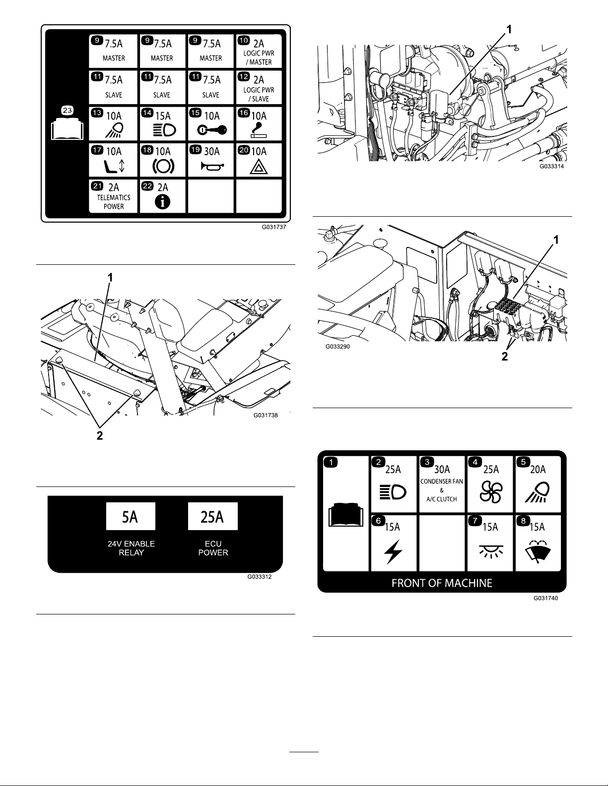
Figure107
G033312
24V ENABLE
RELAY
ECU
POWER
Figure108
g033314
Figure110
1.Fuseblock
g031737
g033290
Figure111
1.Fuseblock2.Powerleads
Thecabfuses(Figure112)arelocatedinthefusebox
g031738
onthecabheadliner(Figure113).
1.Power-centerconsole2.Knobs
Figure109
g033312
g031740
Figure112
77
Page 78

Figure113
ChargingtheBatteries
WARNING
Chargingthebatteriesproducesgassesthat
canexplode.
Donotsmokenearthebattery,andkeep
sparksandamesawayfromthebatteries.
Important:Keepthebatteriesfullycharged.This
g032673
isespeciallyimportanttopreventbatterydamage
whenthetemperatureisbelow32°F(0°C).
1.Cabfusebox
2.Fuses
CheckingtheConditionof theBatteries
ServiceInterval:Every50hours—Checkthe
conditionofthebatteries.
Important:Beforeweldingonthemachine,
disconnectthebatterytopreventdamagetothe
electricalsystem.Also,youmustdisconnect
theenginecontroller,InfoCenter,andmachine
controllersbeforeweldingonthemachine.
Note:Checkthebatteryconditionweeklyorafter
every50hoursofoperation.Keeptheterminalsand
theentirebatterycaseclean,becauseadirtybattery
dischargesslowly.T ocleanthebattery,washthe
entirecasewithasolutionofbakingsodaandwater.
Rinsewithclearwater.Coatthebatterypostsand
cableconnectorswithGrafo112X(skin-over)grease
(ToroPartNo.505-47)orpetroleumjellytoprevent
corrosion.
1.Performthepre-maintenanceprocedure;refer
toPre-MaintenanceSafety(page64).
2.Cleantheexteriorofthebatterycaseandthe
batteryposts.
Note:Connecttheleadsofthebatterycharger
tobatterypostsbeforeconnectingthecharger
totheelectricalsource.
3.Removethecoversfromthejumpposts(Figure
114).
g031800
Figure114
1.Jump-postcovers
4.Connectthepositiveleadofthebatterycharger
tothepositivejumppost(Figure115).
78
Page 79

Figure115
1.Parkthemachineonalevelsurface,stopthe
engine,andremovetheignitionkey.
2.Sitintheoperatorseatandhavetheother
personmaketheconnections.
Note:Ensurethatthejumperbatteryisa
12-voltbattery.
Important:Ifyouareusinganothermachine
forpower,ensurethatthe2machinesare
nottouchingeachother.
3.Removethecoversfromthejumpposts(Figure
114).
4.Connectthepositive(+)jumpercabletothe
positivejumppost(Figure116).
g033269
1.Positive(+)jumppost3.Negative(-)jumper-cable
clamp
2.Negative(-)jumppost4.Positive(+)jumper-cable
clamp
5.Connectthenegativeleadofthebatterycharger
tothenegativejumppost(Figure115).
6.Connectthebatterychargertotheelectrical
source,andchargethebatteryaccordingtothe
Battery-chargingT ablethatfollows.
Important:Donotoverchargethebattery.
Battery-chargerT able
ChargersettingChargingtime
4to6amperes30minutes
25to30amperes10to15minutes
7.Whenthebatteriesarefullycharged,unplug
thechargerfromtheelectricalsource,then
disconnectthechargerleadsfromthejump
posts(Figure115).
g033269
Figure116
1.Positive(+)jumppost3.Negative(-)jumper-cable
clamp
2.Negative(-)jumppost4.Positive(+)jumper-cable
clamp
5.Connectthenegative(-)jumpercabletothe
negativejumppost(Figure116).
Jump-StartingtheMachine
WARNING
Jump-startingthebatterycanproducegasses
thatcanexplode.
Donotsmokenearthebatteryandkeep
sparksandamesawayfrombattery.
Note:Thisprocedurerequires2peopletoperform.
Ensurethatthepersonmakingtheconnectionswears
theproperfaceprotection,protectivegloves,and
clothing.
6.Starttheengine.
Important:Iftheenginestartsandthen
stops,donotoperatethestartermotoruntil
thestartermotorstopsturning.Donot
operatethestartermotorformorethan30
secondsatonetime.Wait30secondsbefore
operatingthestartermotortocoolthemotor.
7.Whentheenginestarts,havetheotherperson
disconnectthenegative(-)jumpercablefrom
thenegativejumppostandthendisconnectthe
positive(+)jumpercable(Figure1 16).
79
Page 80

DriveSystem
Maintenance
CalibratingtheTraction Pedal
ServiceInterval:Every1,000hours—Calibratethe
tractionpedal.
ContactyourlocalT orodistributororrefertotheToro
ServiceManualforassistance.
Adjustingthe
g034932
Figure118
Traction-PedalAngle
Youcanadjusttheoperatingangleofthetraction
pedalforyourcomfort.
1.Loosenthe2nutsandboltssecuringtheleftside
ofthetractionpedaltothebracket(Figure1 17).
Figure117
1.Tractionpedal2.Mountingnutsandbolts
1.Outsidedistance
2.T oadjustthetoe-in,loosentheclampsatboth
endsofthetierods(Figure1 18).
3.Rotatethetie-rodtomovethefrontofthetire
inwardoroutward.
4.Onceyouachievethecorrecttoe-in,tightenthe
tie-rodclamps.
g009745
2.Tie-rodclamps
2.Pivotthepedaltothedesiredoperatingangle
andtightenthenuts(Figure117).
CheckingtheRearWheel Toe-In
ServiceInterval:Every1,000hours—Checktherear
wheeltoe-in.
1.Withthereartiresinastraightposition,measure
theoutsidedistance(ataxleheight)atthefront
andrearofthereartires(Figure118).
Note:Thefrontmeasurementshouldbe0
to3mm(0to0.12inch)greaterthantherear
measurement.
80
Page 81

CoolingSystem
Maintenance
CoolingSystemSafety
CAUTION
Dischargeofhot,pressurizedcoolantor
touchingahotradiatorandsurroundingparts
cancausesevereburns.
•Donotremovetheradiatorcapwhenthe
engineishot.Alwaysallowtheengineto
coolatleast15minutesoruntiltheradiator
capiscoolenoughtotouchwithout
burningyourhandbeforeremovingthe
radiatorcap.
•Donottouchtheradiatorandsurrounding
partsthatarehot.
DANGER
Swallowingenginecoolantcancause
poisoning.
•Donotswallowenginecoolant.
•Keepoutofreachfromchildrenandpets.
DANGER
Therotatingfansanddrivebeltscancause
personalinjury .
•Donotoperatethemachinewithoutthe
coversinplace.
•Keepngers,hands,andclothingclearof
therotatingfananddrivebelt.
•Shutofftheengine,removetheignition
key,andturnthebattery-disconnectswitch
totheOFFpositionbeforeperforming
maintenance.
CAUTION
Iftheenginehasbeenrunning,the
pressurized,hotcoolantcanescapeand
causeburns.
•Donotopentheradiatorcapwhenthe
engineisrunning.
•Usearagwhenopeningtheradiatorcap,
andopenthecapslowlytoallowsteamto
escape.
1.Carefullyremovetheradiatorcapand
expansion-tankcap(Figure119).
Checkingthe Engine-CoolingSystem
ServiceInterval:Beforeeachuseordaily—Check
theengine-coolantlevelinthe
overowreservoir.
Every100hours—Inspectthecooling-system
hoses.
Thecapacityofthesystemonamachinewithouta
cabis10.4L(13.5USqt)andwithacabis17L(18
USqt).
RecommendedCoolant
Note:CoolantmustmeetorexceedASTMStandard3306
Glycolbasedpre-dilutedcoolant(50/50blend)
or
Glycol-basedcoolantmixedwithdistilledwater(50/50blend)
or
Glycol-basedcoolantmixedwithgoodqualitywater(50/50
blend)aslistedintheCumminsManual
CaCO
+MgCO
3
Chloride<40ppm(CI)
Sulfur<100ppm(SO
3
<170ppm
)
4
g031320
Figure119
1.Expansion-tankcap2.Radiatorcap
2.Checkthecoolantlevelintheradiator(Figure
119).
Note:Whencool,theradiatorshouldbelled
tothetopofthellerneckandtheexpansion
tanklledtotheFullmark.
3.Ifthecoolantislow,addtherecommended
replacementcoolanttotheexpansiontankto
theFullmark.
Note:Donotusewateronlyor
alcohol/methanol-basedcoolants.
4.Installtheradiatorcapandexpansion-tankcap.
81
Page 82

CleaningtheCooling Systems
ServiceInterval:Beforeeachuseordaily
Performthepre-maintenanceprocedure;referto
Pre-MaintenanceSafety(page64).
Important:Donotusewatertocleantheradiator
coreorhydraulic-uid-coolercore.Cleaning
theradiatorcoreorhydraulic-uid-coolercore
withwatercanpromoteprematurecorrosionand
damagetocomponents.
CleaningtheRadiator
1.Raisethehoodtothefully-openposition.
2.Pivottheengine-coolingfansrearwardofthe
radiatorandlocktheproprodintothenotch
(Figure120).
Figure120
g033277
Figure121
1.Proprod3.Radiator
2.Engine-coolingfans
CleaningtheHydraulic-Fluid
Cooler
1.Raisethehoodtothefully-openposition.
2.Pivotthehydraulic-coolingfansupwardandlock
theproprodintothenotch(Figure122).
g033276
1.Proprod3.Radiator
2.Engine-coolingfans
3.Usingclean,compressedair,blowthedebris
fromtheenginesiderearwardtocleanthe
radiatorcore.
4.Pivottheengine-coolingfansforwardandlock
theproprodintothenotch(Figure121).
Figure122
1.Hydraulic-uidcooler
2.Hydraulic-coolingfans
3.Proprod
3.Usingclean,compressedair,blowthedebris
fromtheenginesideupwardtocleanthecooling
core.
4.Pivotthehydraulic-coolingfansdownwardand
locktheproprodintothenotch(Figure123).
82
g033288
Page 83

Figure123
g033289
1.Hydraulic-uidcooler
2.Hydraulic-coolingfans
3.Proprod
Changingthe
Engine-CoolingSystemFluid
ServiceInterval:Every1,000hours—Flushthe
engine-coolingsystemandreplace
theuid.
Thecapacityofthesystemonamachinewithouta
cabis10.4L(13.5USqt)andwithacabis17L(18
USqt).
1.Performthepre-maintenanceprocedure;refer
toPre-MaintenanceSafety(page64).
2.Removetheradiatorcap.
3.Withtheradiator-drainhoseplacedinadrain
pan,openthedrainvalveontheradiatorhose
anddraintheuidintoadrainpan(Figure124).
g031321
Figure124
1.Drainvalve3.Radiator
2.Radiator-drainhose
4.Closethevalveontheradiator-drainhose
(Figure124).
5.Filltheradiatorwithcoolantuntilthecoolant
levelevenwiththelipofthellerport(Figure
125).
g034933
Figure125
1.Radiatorcap2.Reserve-tankcap
6.Installtheradiatorcap.
7.Removethecoolanthosefromtheengine-oil
cooler(Figure126).
83
Page 84

Figure126
BeltMaintenance
Servicingthe12V AlternatorBelt
ServiceInterval:Aftertherst10hours
Every1,000hours
Refertotheengineowner'smanual(includedwiththe
g034935
machine)fortheservicingprocedure.
1.Coolanthose
8.Afterdrainingtheenginecoolant,closethedrain
valveontheradiator-drainhoseandconnectthe
coolanthose.
9.Removethecapoftheexpansiontankandll
ittotheLowmarkwithenginecoolant.Install
thecap.
10.Startandruntheengineuntilitreaches
operatingtemperature.
11.Checktheengine-coolantlevel;referto
CheckingtheEngine-CoolingSystem(page81).
12.Addcoolanttotheexpansiontanktobringthe
coolantleveltotheFullmark.
13.Checkallengine-coolant-hoseconnectionsfor
leaks.
Servicingthe24V AlternatorBeltandAC CompressorBelt
ServiceInterval:Aftertherst10hours
Every1,000hours
TheACcompressorand24Valternatorbeltusesa
spring-loadedtensionerthatispre-setatthefactory.
RefertotheToroServiceManualfortheservicing
procedure.
ReplacingtheBlade-Drive Belts
ServiceInterval:Every50hours—Inspectthe
blade-drivebelts.
Every1,000hours—Replacetheblade-drive
belts.
Theblade-drivebelt,tensionedbythespring-loaded
idlerpulley,isverydurable.However,aftermany
hoursofuse,thebeltwillshowsignsofwear.Signs
ofawornbeltaresquealingwhenthebeltisrotating;
bladesslippingwhencuttinggrass;frayededges;
burnmarks;andcracks.Replacethebeltifanyof
thesesignsoccur.
ReplacingtheFrontMower-Deck
Belts
1.Lowerthemowerdecktotheoor.
2.Removethebeltcoversfromthetopofthe
mowerdeckandsetthecoversaside.
3.Onthefrontdeck,centerposition,loosenthe
jamnutsontheidlerpulleystopscrewand
threadthestopscrewintothebracket(Figure
127).
84
Page 85

1.Idler-stopscrew
114-0922
2.Idlerpulley
Figure127
3.2.5mmto4mm(0.10to
0.16inch)
8.Routethenewbeltaroundthespindlepulleys
andidler-pulleyassembly(Figure129).
decal114-0922nc
Figure129
9.Adjustthestopscrewontheidlerpulleyand
tightenthejamnuts.
10.Installthebeltcovers.
ReplacingtheWingMower-Deck
g009014
Belts
Note:Toremovethelowerbelt,youmustremove
theupperbeltrst.
1.Lowerthemowerdecktotheoor.
4.Usingaratchetwrenchorsimilartool,move
eachwing-deckidlerpulleyawayfromthedrive
belttoreleasethebelttensionandallowthebelt
toslipoffthewing-deckpulley(Figure127).
5.Removetheboltssecuringthehydraulicmotor
tothemowerdeck(Figure128).
Figure128
1.Mountingbolts2.Hydraulicmotor
2.Removethebeltcoversfromthetopofthe
mowerdeckandsetthecoversaside.
3.Removetheboltssecuringthehydraulicmotor
tothemowerdeck(Figure128).
4.Liftthemotoroffthemowerdeckandlayiton
topofthemowerdeck.
5.Usingaratchetwrenchorsimilartool,movethe
idlerpulleysawayfromthedrivebelttorelease
thebelttensionandallowthebelttoslipoffthe
pulleys(Figure130).
g031805
6.Liftthemotoroffthemowerdeckandlayiton
topofthemowerdeck.
7.Removetheoldbeltfromaroundthespindle
pulleysandidlerpulley.
85
Page 86

HydraulicSystem
Maintenance
HydraulicSystemSafety
WARNING
Hydraulicuidescapingunderpressurecan
penetrateskinandcauseinjury.
•Ensurethatallhydraulic-uidhoses
andlinesareingoodconditionandall
hydraulicconnectionsandttingsaretight
beforeapplyingpressuretothehydraulic
system.
Figure130
1.Idlerpulleys
6.Removetheoldbeltfromaroundthespindle
pulleysandidlerpulley.
7.Routethenewbeltaroundthespindlepulleys
andidler-pulleyassembly(Figure131and
Figure132).
Figure131
Rightdeck
g009009
•Keepyourbodyandhandsawayfrom
pinholeleaksornozzlesthateject
high-pressurehydraulicuid.
•Usecardboardorpapertondhydraulic
leaks.
•Safelyrelieveallpressureinthehydraulic
systembeforeperforminganyworkonthe
hydraulicsystem.
•Seekimmediatemedicalattentionifuid
isinjectedintoskin.
CheckingtheHydraulic Fluid
ServiceInterval:Beforeeachuseordaily—Check
thehydraulic-uidlevel.
decal114-0974nc
Thehydraulic-uidreservoirislledatthefactorywith
approximately62.7L(16.6USgallons)ofhigh-quality
hydraulicuid.Checkthelevelofthehydraulic
uidbeforeyoustarttheengineforthersttime
anddailythereafter.
Figure132
Leftdeck
UseToroPremiumAll-SeasonHydraulicFluid
(Availablein5-gallonpailsor55-gallondrums.See
thePartsCatalogorT orodistributorforpartnumbers.)
IftheT orouidisnotavailable,youmayuseother
uidsprovidedthattheymeetallthefollowingmaterial
propertiesandindustryspecications.Consultwith
yourlubricantdistributortoidentifyasatisfactory
product.
decal114-4883nc
Note:T orodoesnotassumeresponsibilityfor
damagecausedbyimpropersubstitutions,souse
onlyproductsfromreputablemanufacturerswhowill
standbehindtheirrecommendation.
86
Page 87

High-ViscosityIndex/Low-PourPoint
Anti-WearHydraulicFluid,ISOVG46
MaterialProperties:
St@40°C42to50 Viscosity,ASTMD445
St@100°C7.6to8.5
ViscosityIndexASTM
D2270
PourPoint,ASTMD97-40°Fto-49°F
FZG,Failstage
Watercontent(newuid)500ppm(maximum)
IndustrySpecications:VickersI-286-S(QualityLevel),
VickersM-2950-S(Quality
Level),DenisonHF-0
140orhigher
Important:TheISOVG46multigradeuid
offersoptimalperformanceinawiderange
oftemperatureconditions.Foroperationin
consistentlyhighambienttemperatures,65°F
(18°C)to120°F(49°C),ISOVG68hydraulicuid
mayofferimprovedperformance.
5.Removethedipstickfromthellerneckand
wipeitwithacleanrag.Insertthedipstickinto
thellerneck,thenremoveitandchecktheuid
level(Figure134).
Note:Theuidlevelshouldbewithinthesafe
operatingrangeonthedipstick.
11orbetter
g009240
Figure134
1.Safeoperatingrange
Important:Manyhydraulicuidsarealmost
colorless,makingitdifculttospotleaks.A
reddyeadditiveforthehydraulic-systemoilis
availablein20ml(2/3oz)bottles.1bottleis
sufcientfor15to22L(4to6USgallons)of
hydraulicoil.OrderToroPartNo.44-2500from
yourauthorizedT orodistributor.
1.Performthepre-maintenanceprocedure;refer
toPre-MaintenanceSafety(page64).
2.Ontherightsideofthemachine,raisethe
accesscovertoexposethehydraulic-tankcap
(Figure133).
Figure133
1.Hydraulic-tankcap
6.Ifthelevelislow,addtheappropriateuidto
raisetheleveltotheuppermark.
7.Installthedipstickandcapontothellerneck.
8.Closethecover.
ChangingtheHydraulic FluidandFilters
ServiceInterval:Every1,000hours
Ifthehydraulicuidbecomescontaminated,contact
yourlocalT orodistributorbecausethesystemmust
beushed.Contaminateduidlooksmilkyorblack
whencomparedtocleanoil.
UseT ororeplacementlters(PartNo.86-6110forthe
leftsideofthemachineandPartNo.75-1310forthe
rightsideofthemachine).
Important:Usinganyotherltermayvoidthe
warrantyonsomecomponents.
1.Positionthemachineonalevelsurface,lower
thecuttingunits,shutofftheengine,engagethe
parkingbrakes,andremovetheignitionkey.
g031318
2.Placealargedrainpanunderthehydraulic-uid
tank.
3.Removethehydraulicreservoircapanddipstick.
3.Cleantheareaaroundthellerneckandcapof
thehydraulictank(Figure133).
4.Removethecapfromthellerneck.
4.Removethedrainplugfromthebottomofthe
tankandletthehydraulicuidowintothepan
(Figure135).
87
Page 88

CheckingtheHydraulic LinesandHoses
ServiceInterval:Every2years—Replacemoving
hydrauliclinesandhoses.
Inspectthehydrauliclinesandhosesdailyfor
leaks,kinkedlines,loosemountingsupports,wear,
loosettings,weatherdeterioration,andchemical
deterioration.Makeallnecessaryrepairsbefore
operatingthemachine.
Figure135
1.Hydrauliclters
5.Installthedrainplugwhenthehydraulicuid
stopsdraining.
6.Cleantheareaaroundthelter-mountingareas.
7.Placeadrainpanunderthelterandremove
thelter(Figure135).
8.Lubricatethenewltergasketandllthelter
withhydraulicuid.
9.Ensurethatthelter-mountingareaiscleanand
screwtheltersonuntilthegasketscontacts
themountingplates;thentightenthelteran
additional1/2turn.
10.Fillthereservoirwithhydraulicuid;referto
CheckingtheHydraulicFluid(page86).
2.Drainplug
Important:Useonlythehydraulicuids
specied.Otheruidscouldcausesystem
damage.
g031319
InspectingtheHydraulic SystemTestPorts
Thetestportsareusedtotestthepressureinthe
hydrauliccircuits.ContactyourlocalTorodistributor
orrefertotheToroServiceManualforassistance.
11.Installthereservoirdipstickandcap.
12.Starttheengineanduseallofthehydraulic
controlstodistributehydraulicuidthroughout
thesystem.
Note:Also,checkforleaks,thenstopthe
engine.
13.Checktheuidlevelandaddenoughtoraise
theleveltotheFullmarkonthedipstick.
Note:Donotoverll.
88
Page 89

MowerMaintenance
Pivoting(Tilting)theFront MowerDeckUpright
Note:Althoughnotneededfornormalmaintenance
procedures,youcanpivot(tilt)thefrontmowerdeck
upright.
1.Raisethefrontmowerdeckslightlyofftheoor.
2.Performthepre-maintenanceprocedure;refer
toPre-MaintenanceSafety(page64).
3.Removetheretainerclipanddisconnectthe
damperassemblyfromthemowerdeck(Figure
136).
g008979
Figure137
Figure136
1.Damperassembly2.Retainerclip
4.Removethehairpincotterandclevispin
securingtheheight-of-cutchainstotherearof
themowerdeck(Figure137).
1.Height-of-cutchain
2.Clevispin
3.Hairpincotter
5.Starttheengine,slowlyraisethefrontmower
deck,stoptheengine,andremovetheignition
key.
6.Wedgeablockofwoodbetweentherearofthe
deckandthemachine(Figure138).
g008980
g008985
Figure138
1.Blockofwood
89
Page 90

Pivoting(Tilting)theFront MowerDeckDown
1.Withthehelpofanotherpersonholdingthefront
ofthemowerdeck,removetheblockofwood.
2.Sitontheseat,starttheengine,andlowerthe
mowerdeckuntilitisslightlyofftheoor.
3.Securetheheight-of-cutchainstotherearof
themowerdeck.
4.Connectthedamperassemblyandsecureit
withtheretainerclip.
AdjustingtheMower-Deck Pitch
MeasuringtheMower-DeckPitch
Themower-deckpitchisthedifferencebetweenthe
heightofcutfromthefronttipofthebladetotheback
tip.Setabladepitchof6.3to9.7mm(0.25to0.38
inch);i.e.,thebacktipofthebladeshouldbe7.5mm
(0.3inch)higherthanthefronttip.
3.Measurefromtheoortothebacktipofthe
wingletbladeandrecordthisdimension.
4.Subtractthefrontdimensionfromtherear
dimensiontocalculatethepitchofeachblade.
5.Loosenthejamnutsonthetoporbottomofthe
height-of-cutchainU-bolt(Figure140).
Note:Loosenortightentheheight-of-cutchain
nutsequally,sothatthedeckremainslevelfrom
sidetoside.
1.Positionthemachineonalevelsurfaceonthe
oor.
2.Setthemowerdecktothedesiredheightofcut.
3.Ensurethatthewingletsareleveltothefront
deckandthefrontdeckislevelsidetoside.
AdjustingtheFrontMower-Deck
Pitch
1.Rotateeachbladesothattheypointstraight
forward(Figure139).
Figure139
g009012
Figure140
1.Height-of-cutchain3.Nut(2)
2.U-bolt
6.Adjusttheothersetofnutstoraiseorlowerthe
rearofthemowerdeckandattainthecorrect
mower-deckpitchbasedontheaveragepitch
ofeachblade.
7.Tightenthejamnuts.
g009150
1.Use1ofthesebladesfor
measuringthefront-blade
height.
2.Usingashortruler,measurefromtheoorto
thefronttipofthefrontbladeandrecordthis
dimension.
2.Use1ofthesebladesfor
measuringtherear-blade
height.
90
Page 91

AdjustingtheWingMower-Deck
Pitch
1.Removethetensioningcapfromthe
caster-spindleshaftandslidethespindleoutof
thecasterarm(Figure141).
Figure141
1.Tensioningcap4.T opaxle-mountinghole
2.Spacers5.Casterwheel
3.Shims
ServicingtheCaster WheelsandBearings
ServiceInterval:Every500hours—Inspect
themowerdeckcaster-wheel
assemblies.
1.Removethelocknutfromtheboltholdingthe
caster-wheelassemblybetweenthecasterfork
orthecaster-pivotarm(Figure142).
g008866
g004738
Figure142
2.Positiontheshims,asrequired,toraiseorlower
thecastorwheeluntilthemowerdeckhasthe
correctpitch.
3.Installthetensioningcap.
ServicingtheCaster-Arm Bushings
Thecasterarmshavebushingspressedintothetop
andbottomofthetube,andaftermanyhoursof
operation,thebushingswear.T ocheckthebushings,
movethecasterforkbackandforthandfromsideto
side.Ifthecasterspindleislooseinsidethebushings,
thebushingsarewornandmustbereplaced.
Removethetensioningcapandcasterfork(Figure
141).
Note:Recordthepositionofthewashersand
spacersbeforeyouremovethemsothatyoudonot
needtoadjustthedeckpitch.
1.Casterwheel
2.Casterfork
2.Graspthecasterwheelandslidetheboltoutof
theforkorpivotarm(Figure142).
3.Removethebearingfromthewheelhuband
allowthebearingspacertofallout(Figure142).
4.Removethebearingfromtheoppositesideof
thewheelhub(Figure142).
5.Checkthebearings,spacer,andinsideofthe
wheelhubforwear.
3.Bearing
4.Bearingspacer
Note:Replaceanydamagedparts.
6.T oassemblethecasterwheel,pushthebearing
intothewheelhub.
Note:Wheninstallingthebearings,presson
theouterraceofthebearing.
7.Slidethebearingspacerintothewheelhuband
pushtheotherbearingintotheopenendofthe
wheelhubtocaptivatethebearingspacerinside
thewheelhub.
8.Installthecaster-wheelassemblybetweenthe
casterforkandsecureitinplacewiththebolt
andlocknut.
91
Page 92

BladeMaintenance
BladeSafety
Note:Thedifferencebetweenthedimensions
obtainedinsteps4and5mustnotexceed3mm
(1/8inch).Ifthedimensionexceeds3mm(1/8
inch),thebladeisbentandmustbereplaced;
refertoRemovingandInstallingaBlade(page
92).
DANGER
Awornordamagedbladecanbreak,anda
pieceofthebladecouldbethrownatyou
orbystanders,resultinginseriouspersonal
injuryordeath.Tryingtorepairadamaged
blademayresultindiscontinuedsafety
certicationoftheproduct.
•Inspectthebladeperiodicallyforwearor
damage.
•Nevertrytostraightenabladethatisbent
orweldabrokenorcrackedblade.
•Replaceawornordamagedblade.
•Usecarewhencheckingtheblades.Wrapthe
bladesorweargloves,andusecautionwhen
servicingtheblades.Onlyreplacetheblades;
neverstraightenorweldthem.
•Onmulti-bladedmachines,takecareasrotating1
bladecancauseotherbladestorotate.
CheckingforaBentBlade
RemovingandInstallinga Blade
Replacethebladeifithitsasolidobject,ifitisout
ofbalance,orifitisbent.AlwaysusegenuineT oro
replacementbladestobesureofsafetyandoptimum
performance.Neverusereplacementbladesmade
byothermanufacturersbecausetheycouldbe
dangerous.
1.Raisethemowerdecktothehighestposition.
2.Performthepre-maintenanceprocedure;refer
toPre-MaintenanceSafety(page64).
3.Blockthemowerdecktopreventitfrom
accidentallyfalling.
4.Grasptheendofthebladeusingaragor
thicklypaddedgloveandremovethebladebolt,
anti-scalpcup,andbladefromthespindleshaft
(Figure144).
Afterstrikingaforeignobject,inspectthemachine
fordamageandmakerepairsbeforerestartingand
operatingtheequipment.T orqueallthespindle-pulley
nutsto176to203N·m(130to150ft-lb).
1.Raisethemowerdeck.
2.Performthepre-maintenanceprocedure;refer
toPre-MaintenanceSafety(page64).
3.Blockthemowerdecktopreventitfrom
accidentallyfalling.
4.Rotatethebladeuntiltheendsfaceforwardand
backward,andmeasurefromtheinsideofthe
mowerdecktothecuttingedgeatthefrontof
theblade(Figure143).
Note:Recordthisdimension.
Figure143
5.Rotatetheoppositeendofthebladeforward
andmeasurebetweenthemowerdeckand
cuttingedgeofthebladeatthesameposition
asinstep4.
g004741
Figure144
1.Bladebolt2.Anti-scalpcup
5.Installtheblade,anti-scalpcup,andbladebolt.
6.T orquethebladeboltto115to149N·m(85to
110ft-lb).
Important:Thecurvedpartoftheblade
mustpointtowardtheinsideofthemower
decktoensurepropermowing.
Note:Afterstrikingaforeignobject,torqueall
g004740
thespindle-pulleynutsto176to203N·m(130
to150ft-lb)andthebladeboltsto1 15to149
N·m(85to1 10ft-lb).
92
Page 93

InspectingandSharpening aBlade
ServiceInterval:Aftertherst10hours
Every50hours
Beforeeachuseordaily
Youmustconsider2areasofthebladewhenchecking
andservicingit:thesailandthecuttingedge.Both
cuttingedgesandthesail,whichistheturned-up
portionoppositeofthecuttingedge,contributetoa
goodqualityofcut.Thesailisimportantbecauseit
liftsthegrassupstraight,therebyproducinganeven
cut.However,thesailgraduallywearsdownduring
operation,whichisnormal.Asthesailwearsdown,
thequalityofcutdegradessomewhat,althoughthe
cuttingedgesaresharp.Thecuttingedgeoftheblade
mustbesharpsothatthegrassiscut,nottorn.A
dullcuttingedgeisevidentwhenthetipsofthegrass
appearbrownandshredded.Sharpenthecutting
edgestocorrectthiscondition.
1.Positionthemachineonalevelsurface,raise
themowerdeck,engagetheparkingbrake,put
thetractionpedalinNEUTRAL,ensurethatthe
PTOswitchisintheOFFposition,shutoffthe
engine,andremovetheignitionkey.
g000276
Figure146
1.Sharpenattheoriginalangle.
Note:Sharpenonlythetopofthecuttingedge
andmaintaintheoriginalcuttingangletoensure
thesharpness.
Note:Thebladewillremainbalancedifthe
sameamountofmetalisremovedfromboth
cuttingedges.
Note:Removethebladesandsharpenthemona
grinder.Aftersharpeningthecuttingedges,installthe
bladewiththeanti-scalpcupandbladebolt;referto
RemovingandInstallingaBlade(page92).
CorrectingaMower-Deck Mismatch
2.Examinethecuttingendsofthebladecarefully
(especiallywheretheatandcurvedpartsofthe
blademeet)asshowninFigure145.
Note:Sincesandandabrasivematerialcan
wearawaythemetalthatconnectstheat
andcurvedpartsoftheblade,checktheblade
beforeusingthemower.Ifyounoticewear,
replacetheblade(Figure145).
Figure145
1.Cuttingedge3.Wear/slotforming
2.Curvedarea4.Crack
3.Examinethecuttingedgesofalloftheblades.
4.Sharpenthecuttingedgesiftheyaredullor
nicked(Figure146).
Whenthereismismatchbetweenthebladesona
singlemowerdeck,thegrassappearsstreakedwhen
itiscut.Youcancorrectthisproblembyensuringthat
thebladesarestraight.
1.Usinga1m(3ft)longcarpenter’slevel,nda
levelsurfaceontheshopoor.
2.Raisetheheight-of-cuttothehighestposition;
refertoAdjustingtheHeightofCut(page38).
3.Lowerthemowerdeckontoaatsurfaceand
removethecoversfromthetopofthemower
deck.
4.Rotatethebladesuntiltheendsfaceforward
andbackward.
5.Measurefromtheoortothefronttipofthe
cuttingedge(recordthisdimension).
g006530
6.Rotatethesameblade,sothattheoppositeend
isforwardandmeasureitagain.
Note:Thedifferencebetweenthedimensions
mustnotexceed3mm(1/8inch).Ifthe
dimensionexceeds3mm(1/8inch),replace
theblade,becauseitisbent.Measureallthe
blades.
7.Ensurethatthedeckislevelfromsidetoside
andadjustasrequired.
8.Installthebeltcovers.
93
Page 94

CabMaintenance
1
2
3
4
1
2
3
g028378
1
2
2
3
g028379
CleaningtheCab
ForMachineswithaCab
Important:Usecarearoundthecabsealsand
lights(Figure147).Ifyouareusingapressure
washer,keepthewasherwandatleast0.6m(2ft)
awayfromthemachine.Donotusethepressure
washerdirectlyonthecabsealsandlightsor
undertherearoverhang.
g028378
Figure148
In-CabAirFilter
Figure147
1.Seal3.Keepwand0.6m(2ft)
2.Light4.Donotpressure-wash
away.
undertherearoverhang.
1.Filter
2.Grate
g034330
Figure149
RearCabAirFilter
1.Filter
2.Grate
3.Screw
g028379
3.Screw
CleaningtheCabAirFilters
ServiceInterval:Every250hours
1.Removethescrewsandgratesfromboththe
in-cabandrearcabairlters(Figure148and
Figure149).
2.Cleantheltersbyblowingclean,oil-free,
compressedairthroughthem.
Important:Ifeitherlterhasahole,tear,or
otherdamage,replacethelter.
3.Installtheltersandthegratewiththethumb
screws.
94
Page 95

Cleaningthe Air-Conditioning-Condenser Coil
ServiceInterval:Every250hoursCleanitmore
frequentlyinextremelydustyordirty
conditions.
1.Performthepre-maintenanceprocedure;refer
toPre-MaintenanceSafety(page64).
2.Disconnectthewireforeachfan(Figure150).
Storage
PreparingtheMachinefor Storage
PreparingtheTractionUnit
1.Thoroughlycleanthetractionunit,mowerdecks,
andtheengine.
Important:Donotusehigh-pressurewater
neartheInfoCenterorengine-controlunit
(ECU),asthismaycausedamage.
2.Checkthetirepressure;refertoCheckingthe
TirePressure(page37).
3.Checkallfastenersforlooseness;tightenas
necessary.
4.Greaseoroilallgreasettingsandpivotpoints
andwipeupanyexcesslubricant;referto
Lubrication(page66).
Figure150
RightFanShown
1.Fan3.Knob
2.Wire
3.Removethe2knobsandremovethefan
assembly.
4.Openthe4latchesontheair-conditioning
assemblyandremovethescreen(Figure151).
Figure151
1.Air-conditioning-condenser
coil
2.Latch
3.Air-conditioningscreen
g032323
5.Lightlysandandusetouch-uppaintonpainted
areasthatarescratched,chipped,orrusted,
andrepairanydentsinthemetalbody.
6.Servicethebatteryandcablesasfollows:
A.Removethebatteryterminalsfromthe
batteryposts.
B.Cleanthebattery,terminals,andpostswith
awirebrushandbaking-sodasolution.
C.Coatthecableterminalsandbatteryposts
withGrafo112Xskin-overgrease(T oroPart
No.505-47)orpetroleumjellytoprevent
corrosion.
D.Slowlychargethebatteryevery60days
for24hourstopreventleadsulfationofthe
battery.
PreparingtheEngine
1.Draintheengineoilfromtheoilpanandinstall
thedrainplug.
g032324
2.Removeandinstallanewoillter.
3.Fillenginewith10.4L(11USqt)ofSAE15W-40
CJ-4motoroil.
4.Starttheengineandrunitatidlespeedfor
approximately2minutes.
5.Removetheairlters(Figure149).
6.Cleantheair-conditioningassembly.
7.Installtheairlters,screen,andfanassembly
(Figure149,Figure150,andFigure151).
8.Connectthewireforeachfan(Figure150).
5.Stoptheengine.
6.Flushthefueltankwithfresh,cleanfuel.
7.Secureallofthefuel-systemttings.
8.Thoroughlycleanandservicetheair-cleaner
assembly.
95
Page 96

9.Sealtheair-cleanerinletandtheexhaustoutlet
withweatherprooftape.
10.Checktheanti-freezeprotectionandadda
50/50solutionofwaterandethyleneglycol
anti-freezeasneededfortheexpectedminimum
temperatureinyourarea.
96
Page 97

Notes:
Page 98

Notes:
Page 99

InternationalDistributorList
Distributor:
AgrolancKft
AsianAmericanIndustrial(AAI)
B-RayCorporation
BrisaGoodsLLC
CascoSalesCompany
CeresS.A.CostaRica
CSSCTurfEquipment(pvt)Ltd.SriLanka
CyrilJohnston&Co.
CyrilJohnston&Co.RepublicofIreland
FatDragon
FemcoS.A.Guatemala
FIVEMANSNew-T echCo.,LtdChina
ForGarderOU
G.Y .K.CompanyLtd.
GeomechanikiofAthensGreece
GolfinternationalTurizm
HakoGroundandGardenSweden
HakoGroundandGarden
HayterLimited(U.K.)
HydroturfInt.CoDubai
HydroturfEgyptLLC
IrrimacPortugal351212388260T oroEuropeNVBelgium3214562960
IrrigationProductsInt'lPvtLtd.India00914424494387ValtechMorocco212537663636
JeanHeybroekb.v.Netherlands31306394611VictusEmakPoland48618238369
Country:
Hungary3627539640
HongKong85224977804
Korea82325512076
Mexico12104952417
PuertoRico7877888383
NorthernIreland442890813121
China
Estonia3723846060
Japan81726325861Riversa
Turkey902163365993
Norway4722907760
UnitedKingdom441279723444
UnitedArabEmirates97143479479T -MarktLogisticsLtd.Hungary3626525500
Egypt2025194308ToroAustraliaAustralia61395807355
PhoneNumber:Distributor:
MaquiverS.A.Colombia
MaruyamaMfg.Co.Inc.
Mountelda.s.CzechRepublic
Mountelda.s.Slovakia
5062391138
94112746100
442890813121ParklandProductsLtd.NewZealand6433493760
8861080841322
5024423277
86-10-63816136
30109350054
4635100000
MunditolS.A.
NormaGarden
OslingerTurfEquipmentSA
OyHakoGroundandGardenAb
Perfetto
PratoverdeSRL.
Prochaska&Cie
RTCohen2004Ltd.
LelyTurfcare
Lely(U.K.)Limited
SolvertS.A.S.
SpyprosStavrinidesLimitedCyprus
SurgeSystemsIndiaLimited
Country:
Japan81332522285
Argentina541148219999
Russia74954116120
Ecuador59342396970
Finland35898700733
Poland48618208416
Italy390499128128
Austria4312785100
Israel97298617979
Spain
Denmark4566109200
UnitedKingdom441480226800
France33130817700
India911292299901
PhoneNumber:
5712364079
420255704220
420255704220
34952837500
35722434131
EuropeanPrivacyNotice
TheInformationToroCollects
ToroWarrantyCompany(T oro)respectsyourprivacy.Inordertoprocessyourwarrantyclaimandcontactyouintheeventofaproductrecall,weaskyou
tosharecertainpersonalinformationwithus,eitherdirectlyorthroughyourlocalT orocompanyordealer.
TheT orowarrantysystemishostedonserverslocatedwithintheUnitedStateswhereprivacylawmaynotprovidethesameprotectionasapplies
inyourcountry.
BYSHARINGYOURPERSONALINFORMATIONWITHUS,YOUARECONSENTINGTOTHEPROCESSINGOFYOURPERSONALINFORMATION
ASDESCRIBEDINTHISPRIV ACYNOTICE.
TheWayT oroUsesInformation
Toromayuseyourpersonalinformationtoprocesswarrantyclaims,tocontactyouintheeventofaproductrecallandforanyotherpurposewhichwetell
youabout.ToromayshareyourinformationwithToro'safliates,dealersorotherbusinesspartnersinconnectionwithanyoftheseactivities.Wewillnot
sellyourpersonalinformationtoanyothercompany.Wereservetherighttodisclosepersonalinformationinordertocomplywithapplicablelawsand
withrequestsbytheappropriateauthorities,tooperateoursystemsproperlyorforourownprotectionorthatofotherusers.
RetentionofyourPersonalInformation
Wewillkeepyourpersonalinformationaslongasweneeditforthepurposesforwhichitwasoriginallycollectedorforotherlegitimatepurposes
(suchasregulatorycompliance),orasrequiredbyapplicablelaw .
Toro'sCommitmenttoSecurityofYourPersonalInformation
Wetakereasonableprecautionsinordertoprotectthesecurityofyourpersonalinformation.Wealsotakestepstomaintaintheaccuracyandcurrent
statusofpersonalinformation.
AccessandCorrectionofyourPersonalInformation
Ifyouwouldliketorevieworcorrectyourpersonalinformation,pleasecontactusbyemailatlegal@toro.com.
AustralianConsumerLaw
AustraliancustomerswillnddetailsrelatingtotheAustralianConsumerLaweitherinsidetheboxoratyourlocalToroDealer.
374-0269RevK
Page 100

TheToroWarranty
ATwo-YearLimitedWarranty
ConditionsandProductsCovered
TheToroCompanyanditsafliate,T oroWarrantyCompany,pursuant
toanagreementbetweenthem,jointlywarrantyourT oroCommercial
product(“Product”)tobefreefromdefectsinmaterialsorworkmanship
fortwoyearsor1500operationalhours*,whicheveroccursrst.This
warrantyisapplicabletoallproductswiththeexceptionofAerators
(refertoseparatewarrantystatementsfortheseproducts).Wherea
warrantableconditionexists,wewillrepairtheProductatnocosttoyou
includingdiagnostics,labor,parts,andtransportation.Thiswarranty
beginsonthedatetheProductisdeliveredtotheoriginalretailpurchaser.
*Productequippedwithanhourmeter.
InstructionsforObtainingWarrantyService
YouareresponsiblefornotifyingtheCommercialProductsDistributoror
AuthorizedCommercialProductsDealerfromwhomyoupurchasedthe
Productassoonasyoubelieveawarrantableconditionexists.Ifyouneed
helplocatingaCommercialProductsDistributororAuthorizedDealer,or
ifyouhavequestionsregardingyourwarrantyrightsorresponsibilities,
youmaycontactusat:
ToroCommercialProductsServiceDepartment
ToroWarrantyCompany
811 1LyndaleAvenueSouth
Bloomington,MN55420-1196
952–888–8801or800–952–2740
E-mail:commercial.warranty@toro.com
OwnerResponsibilities
AstheProductowner,youareresponsibleforrequiredmaintenanceand
adjustmentsstatedinyourOperator'sManual.Failuretoperformrequired
maintenanceandadjustmentscanbegroundsfordisallowingawarranty
claim.
ItemsandConditionsNotCovered
Notallproductfailuresormalfunctionsthatoccurduringthewarranty
periodaredefectsinmaterialsorworkmanship.Thiswarrantydoesnot
coverthefollowing:
•Productfailureswhichresultfromtheuseofnon-Tororeplacement
parts,orfrominstallationanduseofadd-on,ormodiednon-Toro
brandedaccessoriesandproducts.Aseparatewarrantymaybe
providedbythemanufactureroftheseitems.
•Productfailureswhichresultfromfailuretoperformrecommended
maintenanceand/oradjustments.Failuretoproperlymaintainyour
ToroproductpertheRecommendedMaintenancelistedinthe
Operator’sManualcanresultinclaimsforwarrantybeingdenied.
•ProductfailureswhichresultfromoperatingtheProductinanabusive,
negligent,orrecklessmanner.
•Partssubjecttoconsumptionthroughuseunlessfoundtobedefective.
Examplesofpartswhichareconsumed,orusedup,duringnormal
Productoperationinclude,butarenotlimitedto,brakepadsand
linings,clutchlinings,blades,reels,rollersandbearings(sealedor
greasable),bedknives,sparkplugs,castorwheelsandbearings,tires,
lters,belts,andcertainsprayercomponentssuchasdiaphragms,
nozzles,andcheckvalves,etc.
•Failurescausedbyoutsideinuence.Conditionsconsideredtobe
outsideinuenceinclude,butarenotlimitedto,weather,storage
practices,contamination,useofunapprovedfuels,coolants,lubricants,
additives,fertilizers,water,orchemicals,etc.
•Failureorperformanceissuesduetotheuseoffuels(e.g.gasoline,
diesel,orbiodiesel)thatdonotconformtotheirrespectiveindustry
standards.
•Normalnoise,vibration,wearandtear,anddeterioration.
•Normal“wearandtear”includes,butisnotlimitedto,damagetoseats
duetowearorabrasion,wornpaintedsurfaces,scratcheddecalsor
windows,etc.
Parts
Partsscheduledforreplacementasrequiredmaintenancearewarranted
fortheperiodoftimeuptothescheduledreplacementtimeforthatpart.
Partsreplacedunderthiswarrantyarecoveredforthedurationofthe
originalproductwarrantyandbecomethepropertyofT oro.T orowillmake
thenaldecisionwhethertorepairanyexistingpartorassemblyorreplace
it.T oromayuseremanufacturedpartsforwarrantyrepairs.
DeepCycleandLithium-IonBatteryWarranty:
DeepcycleandLithium-Ionbatterieshaveaspeciedtotalnumberof
kilowatt-hourstheycandeliverduringtheirlifetime.Operating,recharging,
andmaintenancetechniquescanextendorreducetotalbatterylife.Asthe
batteriesinthisproductareconsumed,theamountofusefulworkbetween
chargingintervalswillslowlydecreaseuntilthebatteryiscompletelyworn
out.Replacementofwornoutbatteries,duetonormalconsumption,
istheresponsibilityoftheproductowner.Batteryreplacementmaybe
requiredduringthenormalproductwarrantyperiodatowner’sexpense.
Note:(Lithium-Ionbatteryonly):ALithium-Ionbatteryhasapartonly
proratedwarrantybeginningyear3throughyear5basedonthetime
inserviceandkilowatthoursused.RefertotheOperator'sManualfor
additionalinformation.
MaintenanceisatOwner’sExpense
Enginetune-up,lubrication,cleaningandpolishing,replacementoflters,
coolant,andcompletingrecommendedmaintenancearesomeofthe
normalservicesT oroproductsrequirethatareattheowner’sexpense.
GeneralConditions
RepairbyanAuthorizedToroDistributororDealerisyoursoleremedy
underthiswarranty.
NeitherTheToroCompanynorToroWarrantyCompanyisliablefor
indirect,incidentalorconsequentialdamagesinconnectionwiththe
useoftheToroProductscoveredbythiswarranty,includingany
costorexpenseofprovidingsubstituteequipmentorserviceduring
reasonableperiodsofmalfunctionornon-usependingcompletion
ofrepairsunderthiswarranty.ExceptfortheEmissionswarranty
referencedbelow,ifapplicable,thereisnootherexpresswarranty .All
impliedwarrantiesofmerchantabilityandtnessforusearelimitedto
thedurationofthisexpresswarranty.
Somestatesdonotallowexclusionsofincidentalorconsequential
damages,orlimitationsonhowlonganimpliedwarrantylasts,sotheabove
exclusionsandlimitationsmaynotapplytoyou.Thiswarrantygivesyou
speciclegalrights,andyoumayalsohaveotherrightswhichvaryfrom
statetostate.
Noteregardingenginewarranty:
TheEmissionsControlSystemonyourProductmaybecoveredby
aseparatewarrantymeetingrequirementsestablishedbytheU.S.
EnvironmentalProtectionAgency(EPA)and/ortheCaliforniaAirResources
Board(CARB).Thehourlimitationssetforthabovedonotapplytothe
EmissionsControlSystemWarranty.RefertotheEngineEmissionControl
WarrantyStatementsuppliedwithyourproductorcontainedintheengine
manufacturer’sdocumentationfordetails
CountriesOtherthantheUnitedStatesorCanada
CustomerswhohavepurchasedT oroproductsexportedfromtheUnitedStatesorCanadashouldcontacttheirT oroDistributor(Dealer)toobtain
guaranteepoliciesforyourcountry ,province,orstate.IfforanyreasonyouaredissatisedwithyourDistributor'sserviceorhavedifcultyobtaining
guaranteeinformation,contacttheT oroimporter.
374-0253RevD
 Loading...