

Page 1
FormNo.3391-812RevA
Groundsmaster
®
5900and5910
RotaryMower
ModelNo.31598N—SerialNo.315000001andUp
ModelNo.31599N—SerialNo.315000001andUp
Registeratwww.T oro.com.
OriginalInstructions(EN)
*3391-812*A
Page 2
WARNING
CALIFORNIA
Proposition65Warning
Thisproductcontainsachemicalorchemicals
knowntotheStateofCaliforniatocausecancer,
birthdefects,orreproductiveharm.
Dieselengineexhaustandsomeofits
constituentsareknowntotheStateof
Californiatocausecancer,birthdefects,
andotherreproductiveharm.
Becauseinsomeareastherearelocal,state,orfederal
regulationsrequiringthatasparkarresterbeusedonthe
engineofthismachine,asparkarresterisincorporatedwith
themuferassembly.
GenuineT orosparkarrestersareapprovedbytheUSDA
ForestryService.
Important:Thisengineisequippedwithaspark
arrestermufer.ItisaviolationofCaliforniaPublic
ResourceCodeSection4442touseoroperatetheengine
onanyforest-covered,brush-covered,orgrass-covered
landwithoutasparkarrestermufermaintainedin
workingorder,ortheengineconstricted,equipped,and
maintainedforthepreventionofre.Otherstatesor
federalareasmayhavesimilarlaws.
yourproductready.Figure1identiesthelocationofthe
modelandserialnumbersontheproduct.Writethenumbers
inthespaceprovided.
Figure1
Introduction
Thismachineisaride-on,rotary-bladelawnmowerintended
tobeusedbyprofessional,hiredoperatorsincommercial
applications.Itisprimarilydesignedforcuttinggrasson
well-maintainedlawnsinparks,golfcourses,sportselds,
andoncommercialgrounds.Itisnotdesignedforcutting
brush,mowinggrassandothergrowthalongsidehighways,
orforagriculturaluses.
Readthisinformationcarefullytolearnhowtooperateand
maintainyourproductproperlyandtoavoidinjuryand
productdamage.Youareresponsibleforoperatingthe
productproperlyandsafely.
YoumaycontactT orodirectlyatwww .Toro.comforproduct
safetyandoperationtrainingmaterials,accessoryinformation,
helpndingadealer,ortoregisteryourproduct.
YoumaycontactT orodirectlyatwww .Toro.comforproduct
andaccessoryinformation,helpndingadealer,ortoregister
yourproduct.
Wheneveryouneedservice,genuineT oroparts,oradditional
information,contactanAuthorizedServiceDealerorToro
CustomerServiceandhavethemodelandserialnumbersof
1.Modelandserialnumberlocation
ModelNo.
SerialNo.
Thismanualidentiespotentialhazardsandhassafety
messagesidentiedbythesafetyalertsymbol(Figure2),
whichsignalsahazardthatmaycauseseriousinjuryordeath
ifyoudonotfollowtherecommendedprecautions.
Figure2
1.Safetyalertsymbol
Thismanualuses2wordstohighlightinformation.
Importantcallsattentiontospecialmechanicalinformation
andNoteemphasizesgeneralinformationworthyofspecial
attention.
©2014—TheToro®Company
8111LyndaleAvenueSouth
Bloomington,MN55420
Contactusatwww.Toro.com.
2
PrintedintheUSA.
AllRightsReserved
Page 3

Contents
Safety...........................................................................4
SafeOperatingPractices...........................................4
ToroMowerSafety..................................................6
SafetyandInstructionalDecals.................................7
Setup...........................................................................15
1RemoveSideDeckShippingStrapand
Brace................................................................15
2LoweringtheFrontDeckWinglets.........................15
3LevelingtheFrontCenterDeck.............................17
4LevelingtheWingletDeckstotheFrontCenter
Deck.................................................................17
5CheckingtheTirePressure....................................18
6CheckingtheFluidLevels.....................................18
7GreasingtheMachine...........................................18
ProductOverview.........................................................19
Controls...............................................................19
Specications........................................................26
Attachments/Accessories........................................26
Operation....................................................................27
CheckingtheEngineOilLevel.................................27
CheckingtheCoolingSystem...................................27
CheckingtheHydraulicSystem................................27
AddingFuel...........................................................27
CheckingtheTirePressure......................................28
CheckingtheTorqueofWheelLugNuts....................28
AdjustingtheHeight-of-Cut....................................28
AdjustingtheSkids.................................................31
AdjustingtheCuttingUnitAnti-ScalpRollers.............31
CheckingtheMismatchBetweenCutting
Units.................................................................32
AdjustingtheMirrors..............................................33
AimingtheHeadlights............................................33
StartingandStoppingtheEngine..............................33
CheckingtheInterlockSwitches...............................34
PushingorTowingtheMachine................................34
JackingPoints........................................................35
TieDowns............................................................35
OperatingCharacteristics........................................36
ReversingFanOperation.........................................36
OperatingTips......................................................37
Maintenance.................................................................38
RecommendedMaintenanceSchedule(s)......................38
ServiceIntervalChart.............................................39
PremaintenanceProcedures........................................39
InnerWingDeckCovers.........................................39
Lubrication...............................................................40
GreasingtheBearingsandBushings..........................40
EngineMaintenance..................................................43
AirCleanerMaintenance.........................................43
ServicingtheEngineOil..........................................44
AdjustingtheValveClearance..................................45
FuelSystemMaintenance...........................................45
ServicingtheFuelSystem........................................45
ServicingtheWaterSeparator..................................45
ReplacingtheFuelFilter..........................................46
ElectricalSystemMaintenance....................................47
Fuses....................................................................47
BatteryCare...........................................................48
JumpStarting/BatteryCharging..............................48
RecalibrateTractionPedal.......................................48
DriveSystemMaintenance.........................................49
AdjustingtheTractionPedalAngle...........................49
CheckingthePlanetaryDriveGear/Brake
Oil....................................................................49
ChangingthePlanetaryDriveGear/Brake
Oil....................................................................49
CheckingtheRearWheelToe-In..............................50
CoolingSystemMaintenance......................................51
CheckingtheCoolingSystem...................................51
ServicingtheEngineCoolingSystem........................52
BrakeMaintenance....................................................52
AdjustingtheServiceBrakes....................................52
BeltMaintenance......................................................53
ServicingtheAlternatorBelt....................................53
ServicingtheCompressorBelt.................................53
ReplacingtheBladeDriveBelts................................53
FrontCuttingUnit..................................................53
SideCuttingDecks.................................................54
HydraulicSystemMaintenance....................................55
CheckingtheHydraulicFluid...................................55
ChangingtheHydraulicFluidandFilters....................56
CheckingtheHydraulicLinesandHoses....................56
HydraulicSystemTestPorts.....................................57
MowerMaintenance...................................................57
Pivoting(Tilting)theFrontCuttingUnit
Upright.............................................................57
PivotingtheFrontCuttingUnitDown.......................58
AdjustingtheCuttingUnitPitch...............................58
ServicingtheCastorArmBushings...........................59
ServicingtheCastorWheelsandBearings..................59
BladeMaintenance.....................................................60
CheckingforaBentBlade........................................60
RemovingandInstallingtheCutterBlade(s)...............60
InspectingandSharpeningtheCutterBlade(s)............61
CorrectingtheCuttingUnitMismatch.......................62
MiscellaneousMaintenance.........................................62
ServicingtheSparkArrestorMufer.........................62
CleaningtheCabAirFilters(For31599N
Models).............................................................62
CleaningtheAirConditioningCoil...........................63
Storage........................................................................64
PreparingforSeasonalStorage.................................64
3
Page 4

Safety
Thismachinehasbeendesignedinaccordancewith
ANSIB71.4-2012.
Improperuseormaintenancebytheoperatoror
ownercanresultininjury.Toreducethepotential
forinjury,complywiththesesafetyinstructionsand
alwayspayattentiontothesafetyalertsymbol,which
meansCaution,Warning,orDanger—personalsafety
instruction.Failuretocomplywiththeinstructionmay
resultinpersonalinjuryordeath.
•Thoroughlyinspecttheareawheretheequipmentisto
beusedandremoveallobjectswhichmaybethrownby
themachine.
•Replacefaultysilencers/mufers.
•Beforeusing,alwaysvisuallyinspecttoseethatthe
blades,bladebolts,andcuttingassemblyarenotworn
ordamaged.Replacewornordamagedbladesandbolts
insetstopreservebalance.
•Evaluatetheterraintodeterminewhataccessoriesand
attachmentsareneededtoproperlyandsafelyperform
thejob.Onlyuseaccessoriesandattachmentsapproved
bythemanufacturer.
SafeOperatingPractices
Training
•ReadtheOperator'sManualandothertrainingmaterial
carefully.Befamiliarwiththecontrols,safetysigns,and
theproperuseoftheequipment.
•Neverallowchildrenorpeopleunfamiliarwiththese
instructionstousethemower.Localregulationsmay
restricttheageoftheoperator.
•Nevermowwhilepeople,especiallychildren,orpetsare
nearby.
•Keepinmindthattheoperatororuserisresponsiblefor
accidentsorhazardsoccurringtohimselforherself,other
people,orproperty.
•Donotcarrypassengers.
•Alldriversandmechanicsshouldseekandobtain
professionalandpracticalinstruction.Theowneris
responsiblefortrainingtheusers.Suchinstructionshould
emphasize:
–theneedforcareandconcentrationwhenworking
withride-onmachines;
–controlofaride-onmachineslidingonaslopewill
notberegainedbytheapplicationofthebrake.The
mainreasonsforlossofcontrolare:
◊insufcientwheelgrip;
◊beingdriventoofast;
◊inadequatebraking;
◊thetypeofmachineisunsuitableforitstask;
◊lackofawarenessoftheeffectofground
conditions,especiallyslopes;
◊incorrecthitchingandloaddistribution.
•Checkthatoperatorspresencecontrols,safetyswitches,
andshieldsareattachedandfunctioningproperly.Donot
operateunlesstheyarefunctioningproperly.
SafeHandlingofFuels
•Toavoidpersonalinjuryorpropertydamage,use
extremecareinhandlinggasoline.Gasolineisextremely
ammableandthevaporsareexplosive.
•Extinguishallcigarettes,cigars,pipes,andothersources
ofignition.
•Useonlyanapprovedfuelcontainer.
•Neverremovefuelcaporaddfuelwiththeengine
running.
•Allowenginetocoolbeforerefueling.
•Neverrefuelthemachineindoors.
•Neverstorethemachineorfuelcontainerwherethereis
anopename,spark,orpilotlightsuchasonawater
heateroronotherappliances.
•Neverllcontainersinsideavehicleoronatruckor
trailerbedwithaplasticliner.Alwaysplacecontainerson
thegroundawayfromyourvehiclebeforelling.
•Removeequipmentfromthetruckortrailerandrefuelit
ontheground.Ifthisisnotpossible,thenrefuelsuch
equipmentwithaportablecontainer,ratherthanfroma
fueldispensernozzle.
•Keepthenozzleincontactwiththerimofthefueltank
orcontaineropeningatalltimesuntilfuelingiscomplete.
Donotuseanozzlelockopendevice.
•Iffuelisspilledonclothing,changeclothingimmediately.
•Neveroverllfueltank.Replacefuelcapandtighten
securely.
Preparation
•Whilemowing,alwayswearsubstantialfootwear,long
trousers,hardhat,safetyglasses,andearprotection.Long
hair,looseclothingorjewelrymaygettangledinmoving
parts.Donotoperatetheequipmentwhenbarefootor
wearingopensandals.
Operation
•Donotoperatetheengineinaconnedspacewhere
dangerouscarbonmonoxidefumescancollect.
•Mowonlyindaylightoringoodarticiallight.
•Beforeattemptingtostarttheengine,disengagethePTO,
shiftintoneutral,andengagetheparkingbrake.Only
4
Page 5

starttheenginefromtheoperatorsposition.Useseat
belts,ifprovided.
•Rememberthereisnosuchthingasasafeslope.Travel
ongrassslopesrequiresparticularcare.Toguardagainst
overturning:
–Donotstoporstartsuddenlywhengoingupor
downhill.
–Themachinespeedshouldbekeptlowonslopesand
duringtightturns.
–Stayalertforhumpsandhollowsandotherhidden
hazards.
–Nevermowacrossthefaceoftheslope,unlessthe
machineisdesignedforthatpurpose.
•Stayalertforholesintheterrainandotherhiddenhazards.
•Usecarewhenusingheavyequipment.
–Donotturnsharply.Usecarewhenreversing.
–Usecounterweight(s)orwheelweightswhen
suggestedintheOperator'sManual.
•Watchoutfortrafcwhencrossingornearroadways.
•Stopthebladesfromrotatingbeforecrossingsurfaces
otherthangrass.
•Whenusinganyattachments,neverdirectdischargeof
materialtowardbystandersnorallowanyonenearthe
machinewhileinoperation.
•Neveroperatethemachinewithdamagedguards,shields,
orwithoutsafetyprotectivedevicesinplace.Besureall
interlocksareattached,adjustedproperly ,andfunctioning
properly.
•Donotchangetheenginegovernorsettingsoroverspeed
theengine.Operatingtheengineatexcessivespeedmay
increasethehazardofpersonalinjury.
•Beforeleavingtheoperatorsposition:
–Stoponlevelground.
–Disengagethepowertake-offandlowerthe
attachments.
–Changeintoneutralandsettheparkingbrake.
–Stoptheengineandremovethekey.
•Disengagedrivetoattachments,stoptheengineand
removetheignitionkey:
–beforeclearingblockages;
–beforechecking,cleaning,orworkingonthemachine;
–afterstrikingaforeignobject.Inspectthemachine
fordamageandmakerepairsbeforerestartingand
operatingtheequipment.Torqueallthespindlepulley
nutsto176to203N-m(130to150ft-lb)andallthe
bladeboltsto115to149N-m(85to110ft-lb),
–ifthemachinestartstovibrateabnormally(check
immediately).
•Disengagedrivetoattachmentswhentransportingornot
isuse.
•Stoptheengineanddisengagedrivetoattachment:
–beforerefuelling;
–beforemakingheightadjustmentunlessadjustment
canbemadefromtheoperatorsposition.
•Reducethethrottlesettingbeforestoppingengineand,if
theengineisprovidedwithafuelshut-offvalve,turnthe
fueloffattheconclusionofmowing.
•Neverraisedeckwiththebladesrunning.
•Keephandsandfeetawayfromthecuttingunits.
•Lookbehindanddownbeforebackinguptobesureof
aclearpath.
•Slowdownandusecautionwhenmakingturnsand
crossingroadsandsidewalks.
•Donotoperatethemowerundertheinuenceofalcohol
ordrugs.
•Lightningcancausesevereinjuryordeath.Iflightning
isseenorthunderisheardinthearea,donotoperate
themachine;seekshelter.
•Usecarewhenloadingorunloadingthemachineintoa
trailerortruck.
•Theoperatorshallturnonashingwarninglights
whenevertravelingonapublicroad,exceptwheresuch
useisprohibitedbylaw.
MaintenanceandStorage
•Keepallnuts,bolts,andscrewstighttobesurethe
equipmentisinsafeworkingcondition.
•Neverstoretheequipmentwithfuelinthetankinsidea
buildingwherefumesmayreachanopenameorspark.
•Allowtheenginetocoolbeforestoringinanyenclosure
anddonotstorenearame.
•Toreducetherehazard,keeptheenginecompartment,
silencer/mufer,batterycompartment,cuttingunits,
drives,andfuelstorageareafreeofgrass,leaves,or
excessivegrease.Cleanupoilorfuelspillage.
•Replacewornordamagedpartsforsafety.
•Ifthefueltankhastobedrained,dothisoutdoors.
•Onmulti-bladedmachines,takecareasrotatingoneblade
cancauseotherbladestorotate.
•Whenmachineistobeparked,stored,orleftunattended,
lowerthecuttingunitsunlessapositivemechanicallock
isprovided.
•Disengagedrives,lowerthecuttingunits,movetraction
pedaltoNeutral,setparkingbrake,movethethrottle
switchtothelowidleposition,stopengineandremove
ignitionkey.Waitforallmovementtostopbefore
adjusting,cleaningorrepairing.
•Shutofffuelwhilestoringortransporting.Donotstore
fuelnearames.
•Parkmachineonlevelground.Neverallowuntrained
personneltoservicemachine.
•Usejackstandstosupportcomponentswhenrequired.
•Carefullyreleasepressurefromcomponentswithstored
energy.
5
Page 6

•Disconnectbatterybeforemakinganyrepairs.Disconnect
thenegativeterminalrstandthepositivelast.Reconnect
positiverstandnegativelast.
•Usecarewhencheckingblades.Wrapthebladesor
weargloves,andusecautionwhenservicingthem.Only
replaceblades.Neverstraightenorweldthem.
•Keephandsandfeetawayfrommovingparts.Ifpossible,
donotmakeadjustmentswiththeenginerunning.
•Chargebatteriesinanopenwellventilatedarea,away
fromsparkandames.Unplugchargerbeforeconnecting
ordisconnectingfrombattery.W earprotectiveclothing
anduseinsulatedtools.
•Makesureallhydrauliclineconnectorsaretightandall
hydraulichosesandlinesareingoodconditionbefore
applyingpressuretothesystem.
•Keepyourbodyandhandsawayfrompinholeleaksor
nozzlesthatejecthydraulicuidunderhighpressure.
Usepaperorcardboard,notyourhands,tosearchfor
leaks.Hydraulicuidescapingunderpressurecanhave
sufcientforcetopenetratetheskinandcauseserious
injury.Ifuidisinjectedintotheskinitmustbesurgically
removedwithinafewhoursbyadoctorfamiliarwiththis
formofinjuryorgangrenemayresult.
Hauling
•Usecarewhenloadingorunloadingthemachineintoa
trailerortruck.
•Usefullwidthrampsforloadingmachineintotraileror
truck.
•Tiethemachinedownsecurelyusingstraps,chains,cable,
orropes.Bothfrontandrearstrapsshouldbedirected
downandoutwardfromthemachine
ToroMowerSafety
ThefollowinglistcontainssafetyinformationspecictoToro
productsorothersafetyinformationthatyoumustknowthat
isnotincludedintheCEN,ISO,orANSIstandards.
Thisproductiscapableofamputatinghandsandfeetand
throwingobjects.Alwaysfollowallsafetyinstructionsto
avoidseriousinjuryordeath.
Useofthisproductforpurposesotherthanitsintendeduse
couldprovedangeroustouserandbystanders.
Operation
•Beforeoperatingthemachinebecertainthattheseat
beltsareattached.
•Knowhowtostopthemachineandenginequickly .
•Donotoperatethemachinewhilewearingtennisshoes
orsneakers.
•Wearingsafetyshoesandlongpantsisadvisableand
requiredbysomelocalordinancesandinsurance
regulations.
•Keephands,feet,andclothingawayfrommovingparts
andthemowerdischargeareaandundersideofthe
mowerwhiletheengineisrunning.
•Fillfueltankuntillevelis25mm(1inch)belowthe
bottomofthellerneck.Donotoverll.
•Checkthesafetyinterlockswitchesdailyforproper
operation.Ifaswitchshouldfail,replacetheswitch
beforeoperatingthemachine.
•Checkcarefullyforoverheadclearances(i.e.branches,
doorways,electricalwires)beforedrivingunderany
objectsanddonotcontactthem.
•Donotmowinreverseunlessabsolutelynecessary.
•Reducespeedwhenmakingsharpturns.
•Avoidstartingorstoppingonaslope.Iftireslosetraction,
disengagethebladesandproceedslowlystraightdown
theslope.Avoidraisingthesidecuttingunitsonaslope.
•Avoidturningonslopes.Ifyoumustturn,turnslowly
andgraduallydownhill,ifpossible.
•NeverremovetheROPSfromthemachine.
•Alwaysweartheseatbeltwhenoperatingthemachine.
•Becertainthattheseatbeltcanbereleasedquicklyifthe
machineisdrivenorrollsintoapondorwater.
•Watchfortrafcwhennearorcrossingroads.Always
yieldtheright-of-way.
•Donotmowneardrop-offs,ditches,orembankments.
Themachinecouldsuddenlyturnoverifawheelgoes
overtheedgeofaclifforditchorifanedgegivesway .
•Donotmowonwetgrass.Reducedtractioncouldcause
sliding.
•Machineshouldnotbeusedasatowvehicle.
•Useextracarewithotherattachments.Thesecanchange
thestabilityofthemachine.
•Turnoffthebladeswhennotmowing.
•Foroperatingenvironmentsexceeding43degreesC(110
degreesF),consultToroforspecialmachineneeds.
•Donotoperatetheenginebelow1350rpm.
MaintenanceandStorage
•Donottouchequipmentorattachmentpartswhichmay
behotfromoperation.Allowtocoolbeforeattempting
tomaintain,adjust,orservice.
•Neverstorethemachineorfuelcontainerinsidewhere
thereisanopename,suchasnearawaterheateror
furnace.
•Keepnutsandboltstight,especiallythebladeattachment
bolts.Keepequipmentingoodcondition.
•Iftheenginemustberunningtoperformamaintenance
adjustment,keephands,feet,clothing,andanypartsof
thebodyawayfromthecuttingunits,attachments,and
anymovingparts.Keepeveryoneaway.
6
Page 7
•Checkbrakeoperationfrequently.Adjustandserviceas
required.
•Batteryacidispoisonousandcancauseburns.Avoid
contactwithskin,eyes,andclothing.Protectyourface,
eyes,andclothingwhenworkingwithabattery.
•Batterygasescanexplode.Keepcigarettes,sparks,and
amesawayfromthebattery.
•DonotusehighpressurewaternearInfoCenter.
SafetyandInstructionalDecals
Safetydecalsandinstructionsareeasilyvisibletotheoperatorandarelocatednearanyareaofpotential
danger.Replaceanydecalthatisdamagedorlost.
•Theenginemustbeshutoffbeforecheckingtheoilor
addingoiltothecrankcase.
•Ifmajorrepairsareeverneededorifassistanceisdesired,
contactanAuthorizedToroDistributor.
•Tomakesureofoptimumperformanceandcontinued
safetycerticationofthemachine,useonlygenuineToro
replacementpartsandaccessories.Replacementparts
andaccessoriesmadebyothermanufacturerscouldbe
dangerous,andsuchusecouldvoidtheproductwarranty.
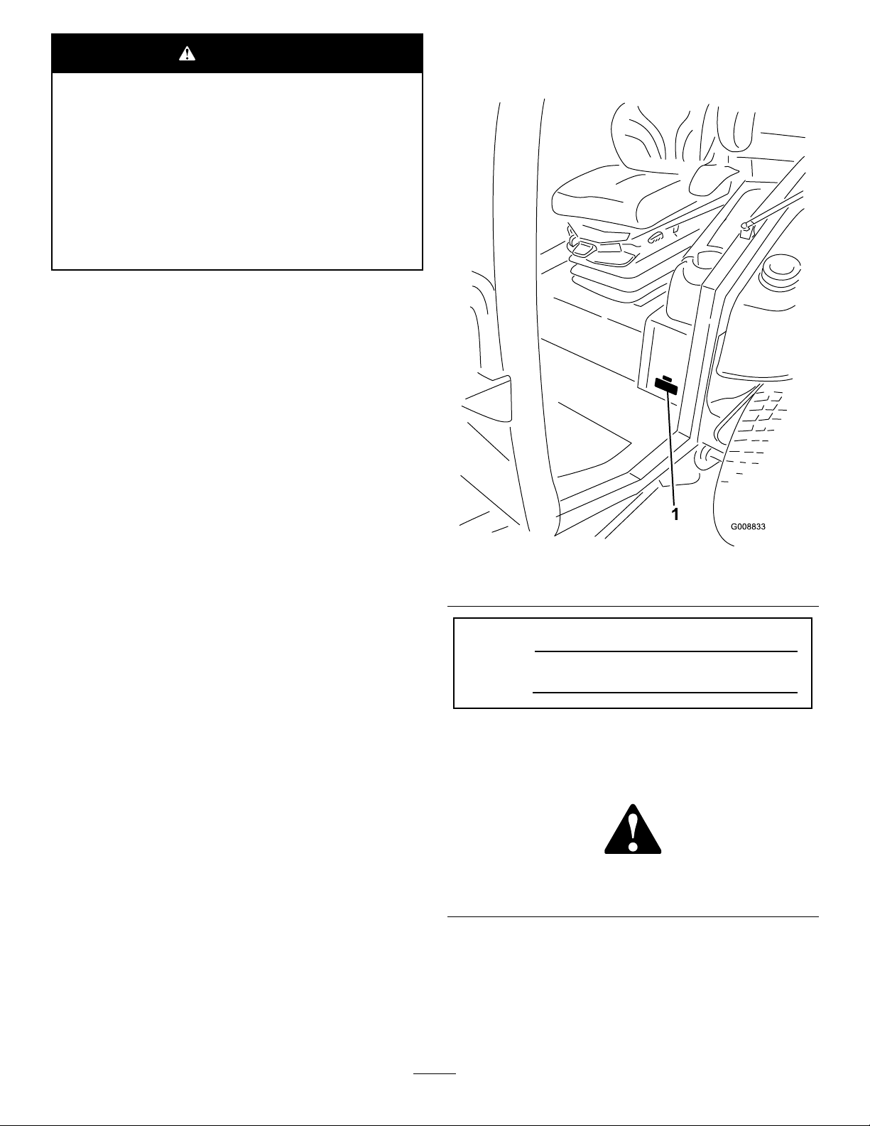
114-0849
1.Warning—disengagethePTOthenraisethedeck.
2.Nostep
3.Tractioncontrolpedal
4.Forward
5.Reverse
121–3883
1.DisengagethePTO3.ReadtheOperator’s
Manual
2.EngagethePTO
121–3884
114-0845
1.Tiltsteeringlever2.Horn
1.Engine—stop3.Engine—start
2.Engine—preheat
7
Page 8
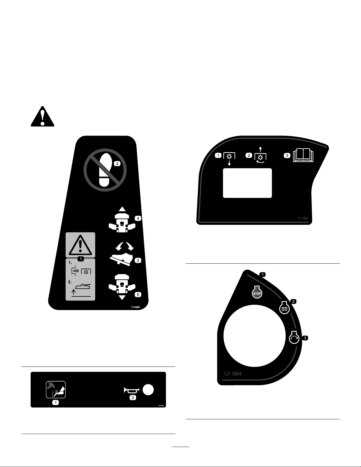
114-0135
1.Raisecuttingunits—left
2.Raisecutting
units—center
3.Raisecuttingunits—right
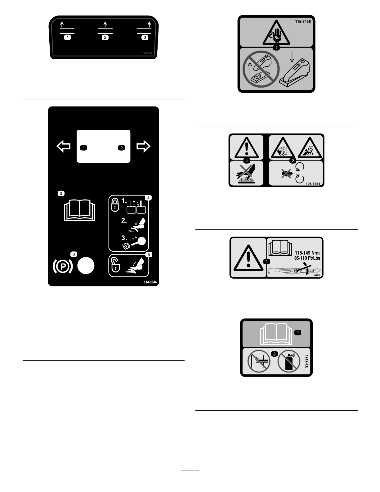
115-5459
1.Electricshockhazard—donotremovecover;keepcoverin
place.
106-6754
1.Warning—donottouchthehotsurface.
2.Cutting/dismembermenthazard,fanandentanglement
hazard,belt—stayawayfrommovingparts.
114-0844
1.Lefthandturnsignal
2.Righthandturnsignal5.Tounlocktheparking
3.ReadtheOperators
Manual.
4.Tolockthebrakes,close
latch,pressthebrake
pedalandpulluponthe
parkingbrakeknob.
brake,pressthebrake.
6.Parkingbrake
93-7818
1.Warning—readtheOperator'sManualforinstructionson
torquingthebladebolt/nutto115-149N-m(85-110ft-lb).
93–7275
1.ReadtheOperator’sManual—donotusestartinguidto
starttheengine.
8
Page 9
93-6674
1.Crushinghazard,hand—readtheinstructionsbefore
servicingorperformingmaintenance.
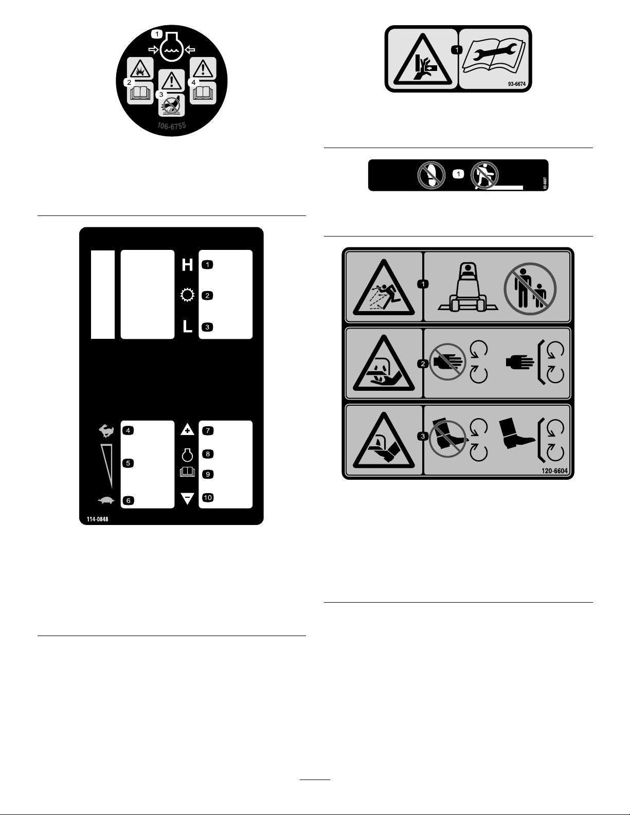
106-6755
1.Enginecoolantunder
pressure.
2.Explosionhazard—read
theOperator'sManual.
3.Warning—donottouchthe
hotsurface.
4.Warning—readthe
Operator'sManual.
93-6687
1.Donotstephere.
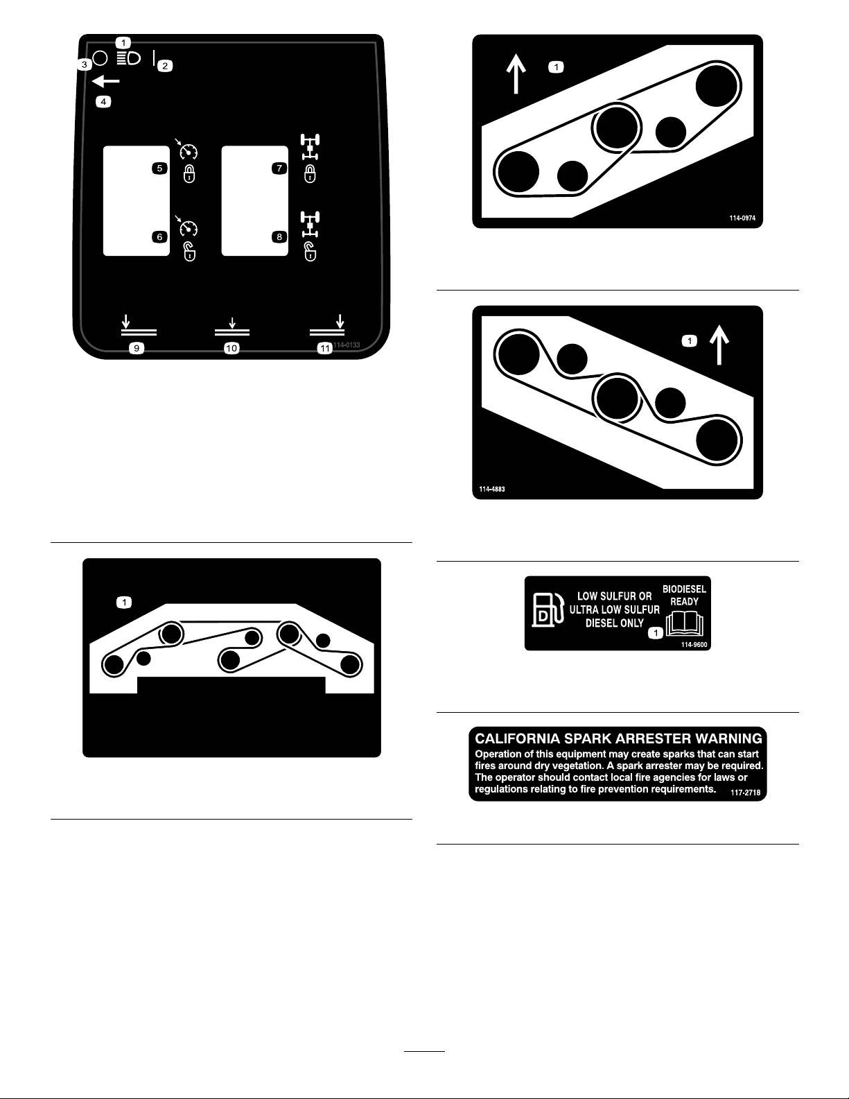
114-0848
1.Highrange6.Lowidle
2.Transmission7.Increaseenginespeed
3.Lowrange8.Engine
4.Highidle
5.Mididle10.Decreaseenginespeed
9.ReadtheOperator’s
Manual.
120-6604
1.Thrownobjecthazard—keepbystandersawayfromthe
machine.
2.Cutting/dismembermenthazardofhand,mower
blade—stayawayfrommovingparts,keepallguardsand
shieldsinplace.
3.Cutting/dismembermenthazardoffoot,mowerblade—stay
awayfrommovingparts,keepallguardsandshieldsin
place.
9
Page 10
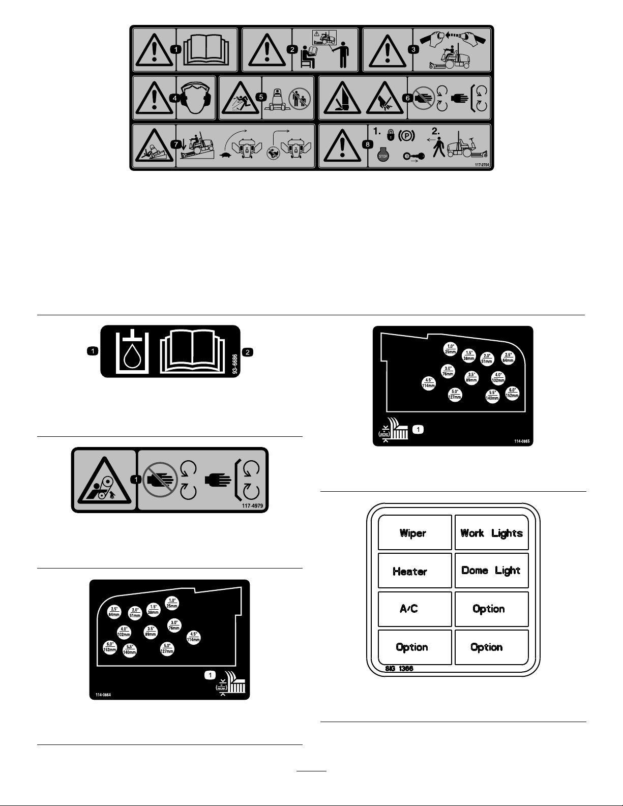
114-0133
114-0922
1.Headlights7.Tractionassist—engage
2.On
3.Off9.Lowercuttingunits—left
4.Headlightswitchlocation10.Lowercutting
5.Cruisecontrol—engage
6.Cruisecontrol—disengage
8.Traction
assist—disengage
units—center
11.Lowercuttingunits—right
114-0974
1.Beltrouting
114-4883
1.Beltrouting
114-9600
1.ReadtheOperator'sManual.
114-0922
1.Beltrouting
117–2718
10
Page 11
117–2754
1.Warning—readtheOperator'sManual.
2.Warning—donotoperatethismachineunlessyouaretrained.
3.Warning—weartheseatbeltwhenseatedintheoperator'sposition.
4.Warning—wearhearingprotection.
5.Thrownobjecthazard—keepbystandersasafedistancefromthemachine.
6.Cuttinghazardofhandorfoot—stayawayfrommovingparts;keepallguardsinplace.
7.Tippinghazard—lowerthecuttingunitwhendrivingdownslopes;slowmachinebeforeturning,donotturnathighspeeds
8.Warning—locktheparkingbrake,stoptheengineandremovetheignitionkeybeforeleavingthemachine.
93-6686
1.Hydraulicoil
2.ReadtheOperator'sManual.
114-0865
1.Heightofcutadjustment
117–4979
1.Entanglementhazard,belt—stayawayfrommovingparts,
keepallguardsandshieldsinplace.
114-0864
1.Heightofcutadjustment
115-5509
(Model31599Nonly)
11
Page 12

115-5489
(Model31599Nonly)
1.Warning—whenthecabwindowsareopenwearhearing
protection.
2.Closetherearwindowbeforeattemptingtoopenthehood.
BatterySymbols
Someorallofthesesymbolsareonyourbattery
1.Explosionhazard
2.Nore,opename,or
smoking.
3.Causticliquid/chemical
burnhazard
4.Weareyeprotection9.Flusheyesimmediately
5.ReadtheOperator's
Manual.
6.Keepbystandersasafe
7.Weareyeprotection;
8.Batteryacidcancause
10.Containslead;donot
distancefromthebattery.
explosivegasescan
causeblindnessandother
injuries
blindnessorsevereburns.
withwaterandgetmedical
helpfast.
discard.
114-0975
1.Height-of-cut
12
Page 13
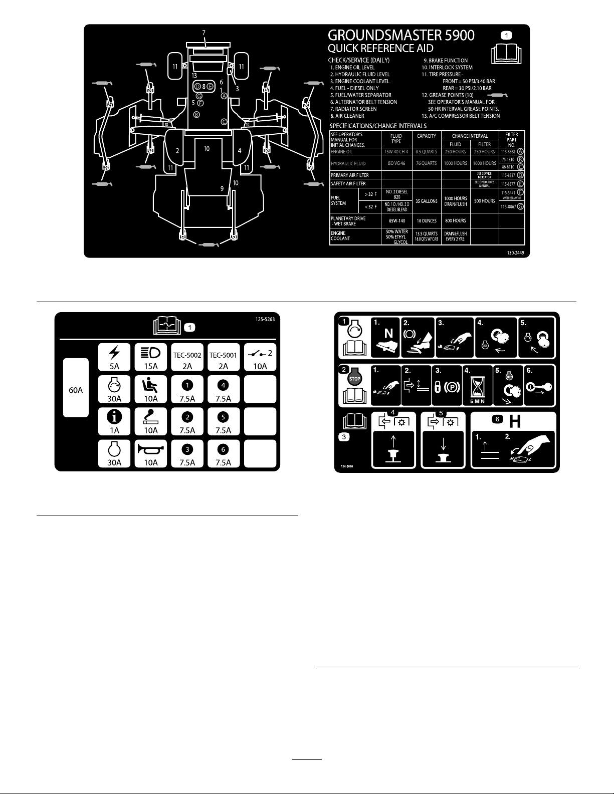
1.ReadtheOperator’sManualforinformationonmaintenance.
130–2449
125–5263
1.ReadtheOperator’sManualforinformationonfuses.
114-0846
1.ReadtheOperatorsManual;tostarttheengine,movethe
tractionpedaltoNeutral,applythebrake,movethethrottle
switchtolow,turntheignitionkeytoPreheat.Whenthe
WaittoStartAdvisoryclearsontheInfoCenterthenturn
theignitionkeytoStart.
2.ReadtheOperatorsManual;tostoptheengine,movethe
throttlelevertoslow,disengagethePTO,settheparking
brake,wait5minutes,turntheignitionkeytoStop,and
removethekey;readtheOperatorsManual.
3.ReadtheOperatorsManual.
4.ToengagethePTO,pulluponthePTOswitch.
5.TodisengagethePTO,pushdownonthePTOswitch.
6.Toswitchthetransmissiontohighspeed,fullyraisethe
attachmentsandswitchthespeedcontroltoHigh.
13
Page 14

130-0458
1.ReadtheOperator's
Manualformore
informationonfuses
2.Electricalpower
accessory—15A
3.Domelight—15A7.Fan—15A
4.Windshieldwiper
uid—15A
5.Headlights—25A
6.CondenserfanandA/C
clutch—30A
8.Worklight—15A
14
Page 15
Setup
LooseParts
Usethechartbelowtoverifythatallpartshavebeenshipped.
ProcedureDescription
1
2
3
4
5
6
7
MediaandAdditionalParts
Description
Operator'sManual
EngineOperator'sManual
OperatorTrainingMaterial
PartsCatalog
Nopartsrequired
DeckcoverR.H.1
DeckcoverL.H.1
V-Belt2
Nopartsrequired
Nopartsrequired
Nopartsrequired
Nopartsrequired
Nopartsrequired
Qty.
1
1
1
1
Providetheoperatorwithinformationontheuseand
maintenanceofthemachine
Orderingparts
Qty.
Use
–
–
–
–
–
–
Removethesidedeckstrapsandbrace
Lowerthefrontdeckwinglets
Levelthefrontcenterdeck
Levelthewingletdeckstothefront
centerdeck
Checkthetirepressure
Checktheuidlevels
Greasethemachine.
Use
DeclarationofConformity
Note:Determinetheleftandrightsidesofthemachine
fromthenormaloperatingposition.
Note:Somepartsmayhavealreadybeeninstalledatthe
factory.
1
RemoveSideDeckShipping StrapandBrace
NoPartsRequired
Procedure
Removethestrapandbracesecuringthesidedecksfor
shipping.
1
2
LoweringtheFrontDeck Winglets
Partsneededforthisprocedure:
1DeckcoverR.H.
1DeckcoverL.H.
2V-Belt
Procedure
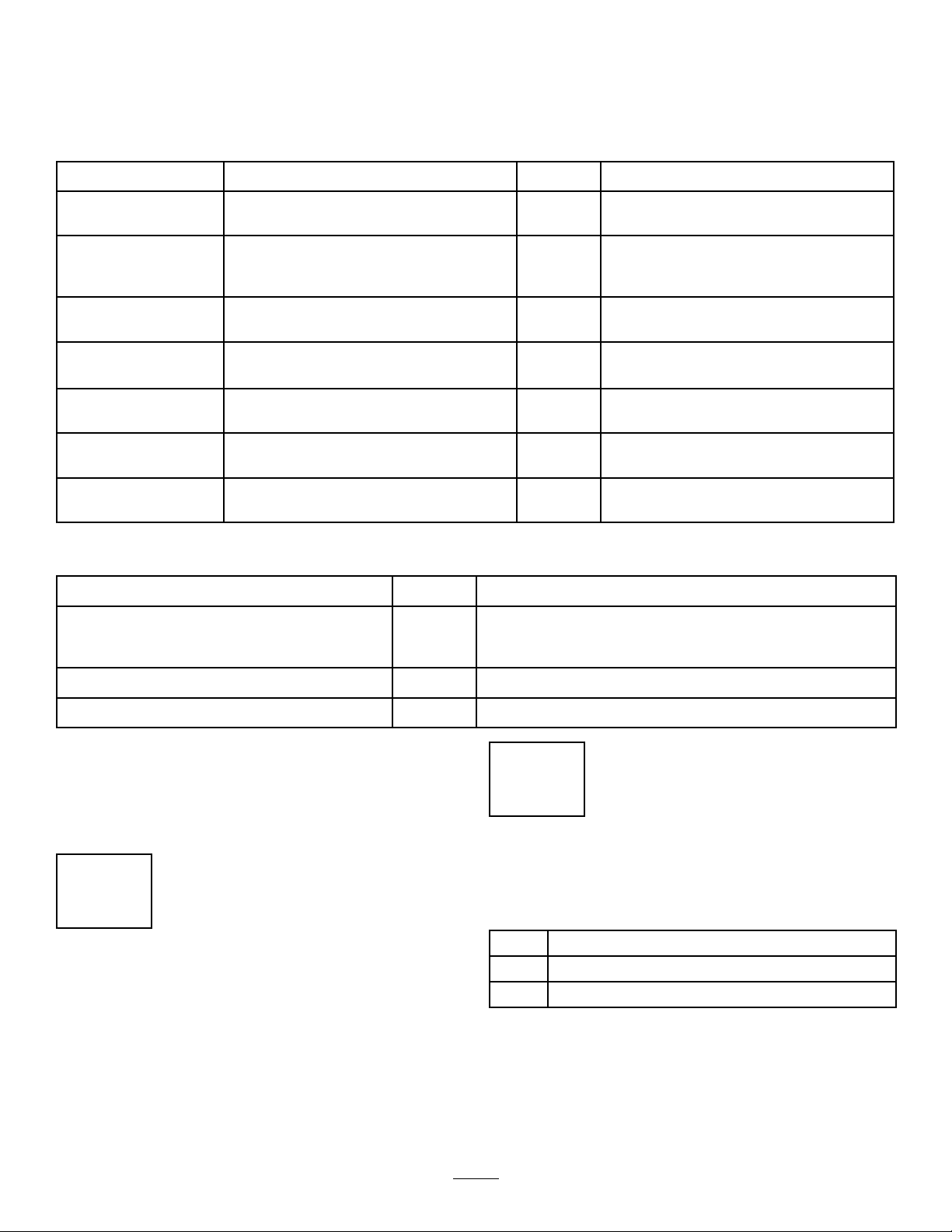
1.Removethenutssecuringthefrontandrearstopbolts
totherightwingletdeckmounts(Figure3).
2.Whilesupportingtherightwinglet,removethefront
andrearstopboltsfromthedeckmounts(Figure
15
Page 16
3).Leavetheeccentricspositionedbetweenthedeck
mounts.
3.Lowerthewinglettotheoperatingposition.
Figure4
1.Winglet4.Eccentric
2.Hingepin5.Lowerhole
3.Bolt
Figure3
1.Winglet4.Eccentric
2.Hingepin5.Upperhole
3.Stopbolt
6.Deckmounts
4.Installthefrontandrearstopboltsthroughtheupper
mountingholesandeccentrics.Makesurethestopbolt
engagesthetabonthehingepin.
5.Installthenutssecuringthestopboltsbutdonot
tightenatthistime.
6.Repeattheprocedureonleftwinglet.
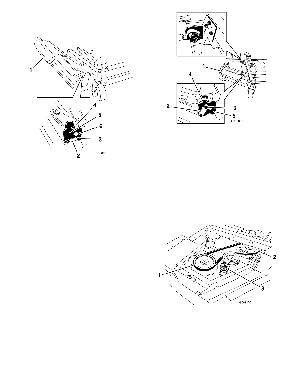
7.Installthewingletbeltsasfollows:
•Startthebeltaroundthewingletspindlepulleyand
thefrontdeckspindlepulley(Figure5).
•Usingaratchetwrenchorsimilartool,movethe
idlerpulleyawayfromthepulleys(Figure5).
•Routethebeltaroundthewingletspindlepulley
andtheupperspindlepulleyonthefrontdeck.
•Releasetheidlerpulleytoputtensiononthebelt.
Figure5
1.Wingletspindlepulley3.Idlerpulleyassembly
2.Frontdeckspindlepulley
8.Installthewingletdeckcoverandsecurewithrubber
latch(Figure6).
16
Page 17
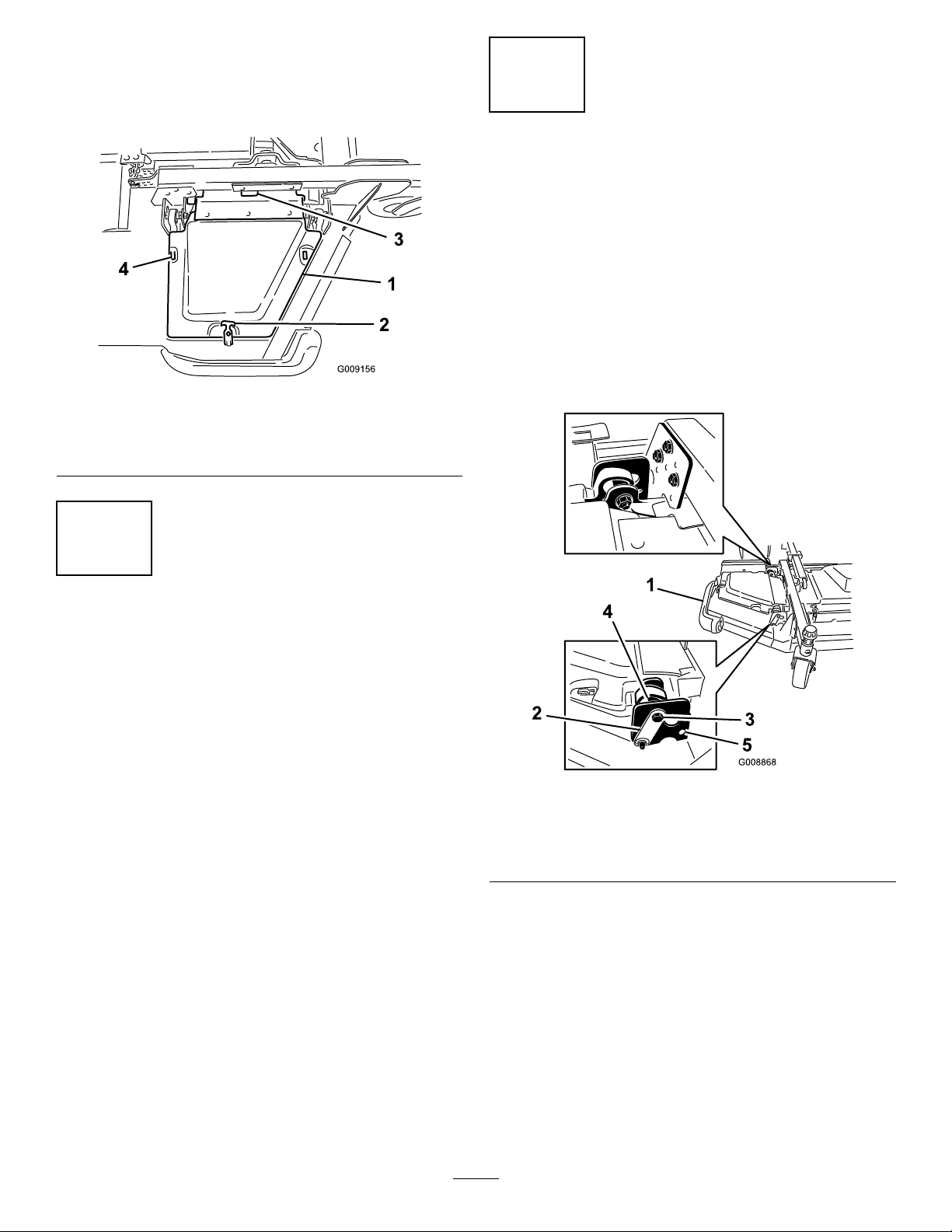
Note:Makesuretoslidethecoverunderthefront
centerdeckcovertabsbeforeinsertingitontothe
mountinghooksandpost.
9.Repeattheprocedureontheotherwinglet.
Figure6
4
LevelingtheWingletDecksto theFrontCenterDeck
NoPartsRequired
Procedure
Levelthewingletdeckstothefrontdeckasfollows:
•Rotatethebladeoneachwingletsothatitpointsside
toside.
•Loosentheboltsandnutssecuringthetwoeccentric
spacerstothewinglets(Figure7).
1.Cover
2.Rubberlatch4.Mounthooks
3.Frontcenterdeckcover
tabs
3
LevelingtheFrontCenterDeck
NoPartsRequired
Procedure
RefertoAdjustingtheHeight-of-CutinOperation.
1.Rotatebladeoneachouterspindleuntiltheendsface
forwardandbackward.
2.Measurefromtheoortothefronttipoftheblade.
Adjustthe1/8inchshimsonthefrontcastorfork(s)
tomatchthedesiredheightofcut.
3.Rotatetheblades180°andnowmeasurefromtheoor
tothe(rearfacing)tipoftheblade.
4.Loosenthelowerjamnutsontheheight-of-cutchain
U-bolt.
5.Adjustthenutstoraiseorlowertherearofthecutting
unitsothatthefrontandrearbladetipshavethesame
measurement.Tightenthejamnuts.
6.Proceedtoprocedure4andlevelthewingletdecksto
thefrontcenterdeck.
Figure7
1.Winglet4.Eccentric
2.Hingepin5.Upperhole
3.Stopbolt
•Rotatetherear(closesttotractionunit)eccentricuntilthe
outsidebladetipisabout3mm(1/8inch)higherthan
thedesiredheightofcut(Figure7).
Note:Thereisanotchontheeccentrichexwhichis
180°fromthelobeontheeccentriccam(Figure8).Use
thenotchestoreferencethelocationofthelobeswhen
adjustingtheeccentrics.
17
Page 18

6
CheckingtheFluidLevels
NoPartsRequired
Procedure
Figure8
1.Eccentricnotch
•Tightentheboltandnutforthiseccentricto149N-m
(110ft-lb).
•Adjusttheforwardeccentricuntilitjustmakescontact
withtheinnerslotsurfaceofthewingletpivotbrackets.
•Tightentheboltandnutforthiseccentricto149N-m
(110ft-lb).
•Repeattheprocedureontheoppositewinglet.Referto
AdjustingtheCuttingUnitPitchprocedureinMower
Maintenance.
5
CheckingtheTirePressure
NoPartsRequired
Procedure
Checktheairpressureinallthetiresbeforeoperatingthe
machine.Thecorrectairpressureinthefronttiresis345kPa
(50psi)andthereartiresis207kPa(30psi)(Figure9).
1.Checktheengineoillevelbeforestartingtheengine,
refertoCheckingtheEngineOilLevelinEngine
Maintenance.
2.Checkthehydraulicuidlevelbeforestartingthe
engine,refertoCheckingtheHydraulicFluidLevelin
HydraulicSystemMaintenance.
3.Checkthecoolingsystembeforestartingtheengine;
refertoCheckingtheCoolingSysteminCooling
SystemMaintenance.
7
GreasingtheMachine
NoPartsRequired
Procedure
Beforethemachineisoperated,itmustbegreasedto
ensureproperlubricatingcharacteristics;refertoGreasing
theBearingsandBushingsprocedureinLubricationinthe
MaintenanceSection.Failuretoproperlygreasethemachine
willresultinprematurefailureofcriticalparts.
Important:Maintainpressureinalltirestoensurea
goodquality-of-cutandpropermachineperformance.
Do not under -inate.
Figure9
18
Page 19
ProductOverview
Controls
Note:Determinetheleftandrightsidesofthemachine
fromthenormaloperatingposition.
CAUTION
Thismachineproducessoundlevelsinexcessof85
dBAattheoperatorsearandcancausehearingloss
throughextendedperiodsofexposure.
Wearhearingprotectionwhenoperatingthis
machine.
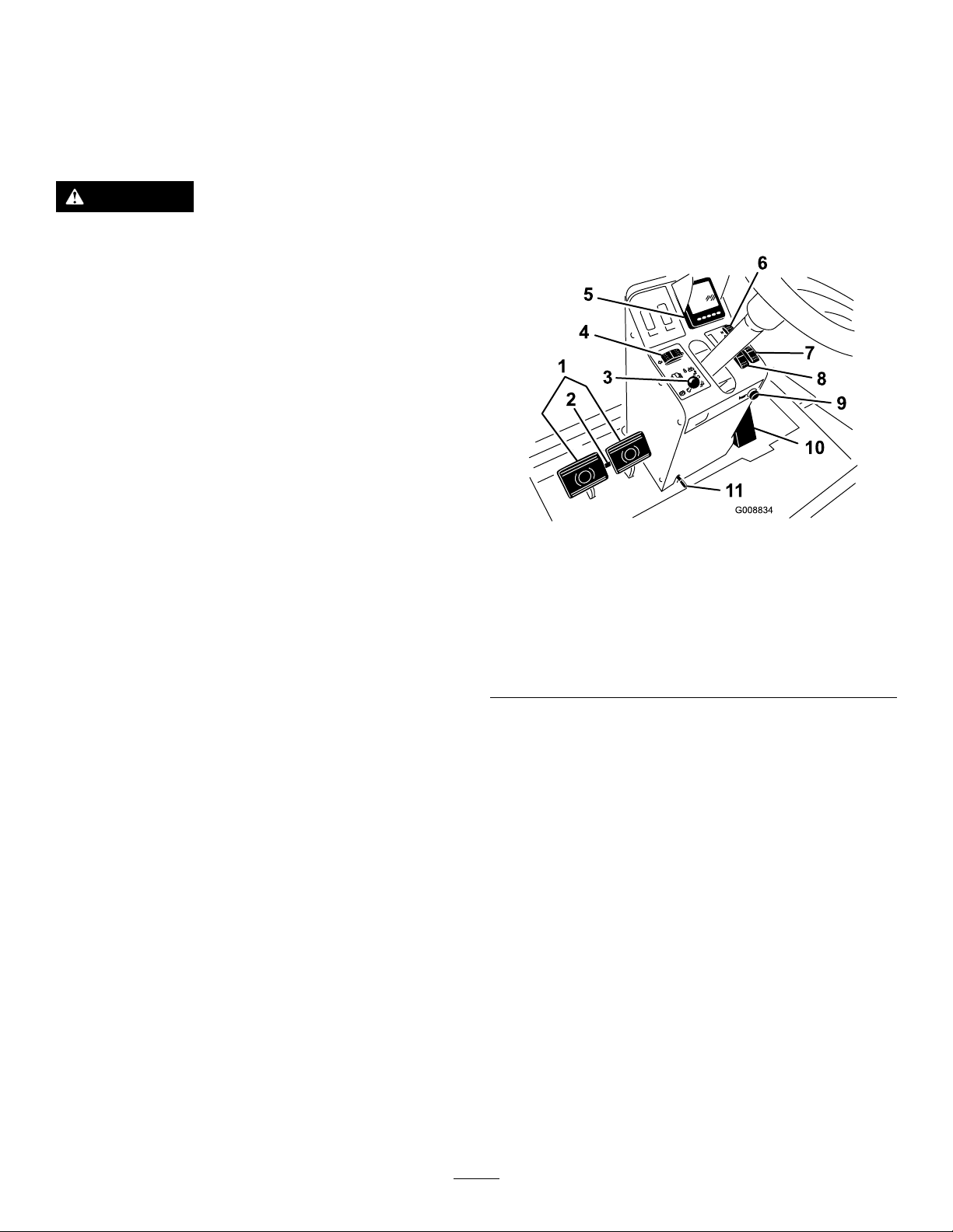
TractionPedal
Thetractionpedal(Figure10)controlsforwardandreverse
operation.Pressthetopofthepedaltomoveforwardand
thebottomtomovebackward.Groundspeeddependson
howfaryoupressthepedal.Fornoload,maximumground
speed,fullypressthepedalwhilethethrottleisintheHi
idleposition.
HornButton
Pressthehornbutton(Figure10)toactivatethehorn.
ParkingBrakeLatch
Theknobontheleftsideoftheconsoleactuatestheparking
brakelock(Figure10).Toengagetheparkingbrake,connect
thepedalswiththelockinglatch,pushdownonbothpedals,
andpulltheparkingbrakelatchout.Toreleasetheparking
brake,pressbothpedalsuntiltheparkingbrakelatchretracts.
Tostop,reduceyourfootpressureonthetractionpedaland
allowittoreturntothecenterposition.
BrakePedals
Twofootpedals(Figure10)operateindividualwheelbrakes
forturningassistance,parking,andtoaidinobtainingbetter
sidehilltraction.Alatchconnectsthepedalsforparking
brakeoperationandtransport.
PedalLockingLatch
Thepedallockinglatch(Figure10)connectsthepedals
togethertoengagetheparkingbrake.
TiltSteeringLever
Pressthelever(Figure10)downtotiltthesteeringwheel
tothedesiredposition.Thenreleasethelevertolockthe
adjustment.
TurnSignalSwitch
Presstheleftsideoftheturnsignalswitch(Figure10)to
activatetheleftturnsignalandtherightsideoftheswitchto
activatetherightturnsignal.Thecenterpositionisoff.
Figure10
1.Brakepedals7.Variablethrottleswitch
2.Pedallockinglatch8.Throttleswitch
3.Parkingbrakelatch9.Horn
4.Turnsignalswitch10.Tractionpedal
5.Infocenter
6.Hi-lorangespeedcontrol
11.Tiltsteeringlever
ThrottleSwitch
Thethrottleswitch(Figure11)hasthreepositionslowidle,
mididleandhighidle.
VariableThrottleSwitch
Thevariablethrottleswitch(Figure11)allowstheengine
speedtobeadjustedinsmallincrements.Pressthe“+”once
toincreasetheenginespeedandthe“-”oncetodecrease
theenginespeed.
Note:Movingthethrottleswitchwilloverrideandcancel
thevariablethrottlesetting.
Important:Donotoperatetheenginebelow1350rpm.
Hi-LoRangeSpeedSwitch
Pressthefrontoftheswitch(Figure10)toselecthighspeed
range.Presstherearoftheswitchtoselectlowspeedrange.
Themachinemustbestationaryortravelingataveryslow
speed,lessthan2mph,toshifttoHiorLo.
LiftSwitches
Theliftswitches(Figure11)raiseandlowerthecuttingunits.
Presstheswitchesforwardtolowerthecuttingunitand
backwardtoraisethecuttingunits.
19
Page 20

Note:ThedeckswillnotlowerwhileintheHispeedrange.
andthedeckswillnotraiseorloweriftheoperatorisoutof
theseatwhentheengineisrunning.
LightSwitch
Presstheloweredgeoftheswitch(Figure11)toturnonthe
lights.Presstheupperedgeoftheswitchtoturnoffthelights.
KeySwitch
Thekeyswitch(Figure11)hasthreepositions:Stop,
Run/Preheat,andStart.
Figure11
1.PTOswitch5.Cruisecontrol
2.Keyswitch6.Lightswitch
3.Tractionassistswitch
4.Liftswitches
7.Powerpoint(ontheright
sideofconsole)
AudibleAlarm(Console)
Thealarmisactivatedwhenafaultisdetected.
Thebuzzersounds:
•continuouswhentheenginesendsastopfault.
•withashortpulsewhentheenginesendsacheckengine
fault.
•whenthereislowfuel.
PowerPoint
Thepowerpoint,locatednexttotheconsoleontheside
ofthepowercenter,isusedtopoweroptionalelectrical
accessories(Figure11).
SeatAdjustments
Weightgauge
Indicateswhentheseatisadjustedtotheweightofthe
operator(Figure12).Heightadjustmentismadeby
positioningthesuspensionwithintherangeofthegreen
region.
PTOSwitch
ThePTOswitch(Figure11)hastwopositions:Out(start)
andIn(stop).PullthePTObuttonouttoengagethe
implementorcuttingunitblades.Pushinthebuttonto
disengagetheimplementoperation.
TractionAssistSwitch
Whenmowing(lowspeedrange),pressandholdthe
tractionassistswitch(Figure11)toenhancetractiondrive
performanceincompromisedoperatingconditions.
Note:ThetractionassistonlyengagesinMow-Forward.
ThetractionassistwillnotengageinMow-ReverseorHi
speedrange.
CruiseControlSwitch
Thecruisecontrolswitch(Figure11)setsthespeedofthe
machine.Pressingtherearoftheswitchturnsoffthecruise
control,themiddlepositionoftheswitchenablesthecruise
controlfunctionandthefrontoftheswitchsetsthedesired
groundspeed.
Note:Pressingeitherbrakepedalormovingthetraction
pedalintothereverseposition,foronesecond,willalso
disengagethecruisecontrol.
Figure12
1.Weightgauge
2.Weightadjustinglever5.Armrestadjustingknob
3.ForeandAftadjusting
lever
WeightAdjustingLever
Adjustforoperatorweight(Figure12).Pulluponthelever
toincreasetheairpressureandpushdowntodecreasetheair
4.Seatbackadjustinglever
20
Page 21
pressure.Theproperadjustmentisattainedwhentheweight
gaugeisinthegreenregion.
ForeandAftAdjustingLever
Pulloutonthelevertoslidetheseatforeoraft(Figure12).
SeatBackAdjustingLever
Movethelevertoadjusttheseatbackangle(Figure12).
SeatArmRestAdjustingKnob
Rotatetheknobtoadjusttheseatarmrestangle(Figure12).
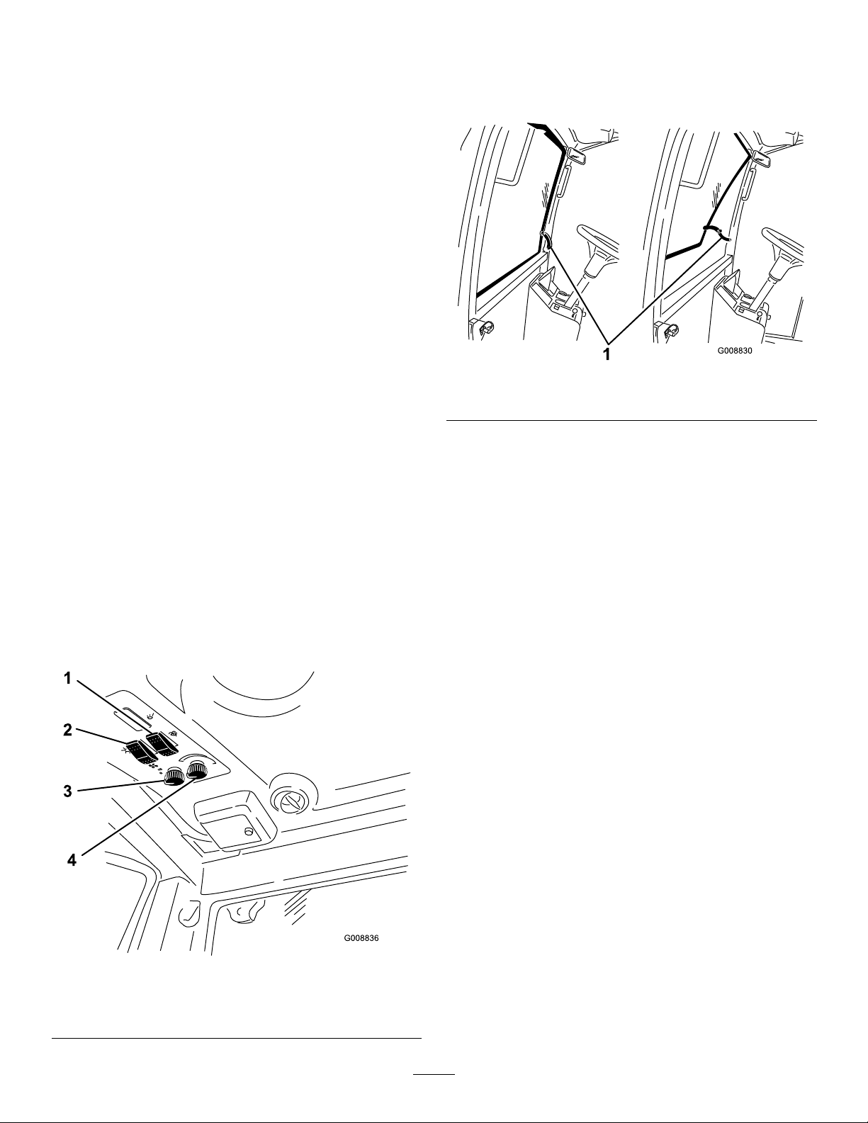
CabControls
Model31599and31599Nonly
WindShieldLatch
Liftuponlatchestoopenthewindshield(Figure14).Press
inonlatchtolockwindshieldinopenposition.Pulloutand
downonlatchtocloseandsecurewindshield.
WindShieldWiperSwitch
Pressfrontofswitchtoactivatethewindshieldwipers
(Figure13)andrearofswitchtoturnoffthewipers.
AirConditioningSwitch
Pressfrontofswitchtoactivatetheairconditioning(Figure
13)andrearofswitchtoturnofftheairconditioning.
FanControl
Rotatethefancontrolknobtoregulatethespeedofthefan
(Figure13).
TemperatureControl
Rotatethetemperaturecontrolknobtoregulatetheair
temperatureinthecab(Figure13).
Figure14
1.Windshieldlatch
RearWindowLatch
Liftuponlatchestoopentherearwindow .Pressinonlatch
tolockwindowinopenposition.Pulloutanddownonlatch
tocloseandsecurewindow(Figure14).
Important:Therearwindowmustbeclosedbefore
openingthehoodordamagemayoccur.
InfoCenter
ScreenFunctions
•Pressthecorrespondingbuttontoviewscreen1orscreen
2,tostopaudiblealarm,toviewfaultscreenortoexit
(Figure15).
•Ifafaultappearsonthescreen,pressanykeytoviewthe
activefaultadvisory.Contactyoursupervisorormechanic
torelayfaultadvisoryanddeterminecourseofaction.
Figure13
1.Windshieldwiperswitch3.Fancontrol
2.Airconditioningswitch4.T emperaturecontrol
•Pressthearrowkeystonavigatethefaultscreen.
•Pressanykeytorevealtheinformationkeysonthescreen.
21
Page 22

1.Screen1
2.Screen2
3.Audiblealarm
Figure15
4.Faultscreen
5.Exit
EngineCoolantTemperatureIndicator
Thisdisplayindicatestheenginecoolanttemperature(Figure
16).
ParkingBrakeIndicator
Thisdisplayindicatesthattheparkingbrakeisactuated
(Figure16).
PTOIndicator
Thisdisplayindicates(Figure16)whenthePTOinengaged.
FanReverseIndicator
Thisdisplayindicates(Figure16)whenthefanisoperating
inreverse.Thefanspeedwillbecontrolledbythehydraulic
oiltemperature,airintaketemperatureorenginecoolant
temperatureandwillautomaticallyreverse.Areversecycleis
automaticallyinitiated,tohelpblowdebrisoffoftherear
hoodscreen,wheneithertheenginecoolanttemperatureor
hydraulicoiltemperatureacertainpoint.
OperatorInformation
Therearetwoscreensthatwillmonitoranddisplaythe
machinefunctionsthattheoperatorcanuse.
Screen1willdisplay:
TopLeftGauge-EngineCoolantTemperature
TopRightGauge-FuelLevel
LefttoRightontheBottomHalf
1.PTOEngaged
2.ParkingBrakeEngaged
3.FanReversing
4.CruiseControlEngaged
5.H/L(Hi/Lowspeedrange)
BottomLeftCorner-AirIntakeHeaterActive
BottomMiddle-TractionAssistEngaged
BottomRight-MachineHours
Screen2willdisplay:
TopLeftCorner-EngineRPM
TopRightCorner-HydraulicOilTemperature
LowerLeftCorner-BatteryVoltage
LowerRightCorner-ServiceDue
CruiseControlIndicator
Thisdisplayindicates(Figure16)whenthecruisecontrolis
inoperation.
FuelLevelIndicator
Thisdisplayindicatestheleveloffuelinthetank(Figure16).
Figure16
1.Enginecoolant
temperatureindicator
2.Fuelindicator7.Tractionassistindicator
3.PTOindicator8.Cruisecontrolindicator
4.Airintakeheaterindicator9.Machinehoursindicator
5.Parkingbrakeindicator
6.Fanreverseindicator
10.H/L(Hi/Low)speed
rangeindicator
22
Page 23

H/L(Hi/Low)SpeedRangeIndicator
g021 157
Thisdisplayindicateswhichspeedrangehasbeenselected
(Figure16).
Note:Whenservicehasbeenperformed,makesuretoreset
theindicator.
ResettingtheServiceIntervalIndicator
AirIntakeHeaterIndicator
Thisdisplayindicateswhenthesystemispreheating(Figure
16).
TractionAssistIndicator
Thisdisplayindicateswhenthetractionassistisengaged
(Figure16).
MachineHoursIndicator
Thisdisplayshowsthetotalhoursthatthemachinehasbeen
operated(Figure17).
1.PressandholdthefarrightbuttonontheInfoCenter.
2.TheMainMenuscreenwillcomeup.SelectSERVICE
usingthe2buttonsontheleft;pressthebuttonbelow
therightarrowtocontinue.
3.SelectHOURSandpressthebuttonbelowtheright
arrow.
4.PressthebuttonbelowRESETHOURS.
5.SelecttheHOURSfortheappropriatenextservice
timeandpressthebuttonbelowtherightarrow .A
checkmarkwillappearonceithasbeenreset.When
nished,pressthebuttonbelowtheexiticon(picture
ofadooropen)toreturntothemainscreen,orpress
canceltoexit.
EngineAirFilterRestrictionIndicator
Thisdisplay(Figure18)indicateswhentheengineairlter
isrestricted.
Figure17
1.Tachometer3.Batteryvoltage
2.Hydraulicoiltemperature
4.Servicedue
Tachometer
ThisdisplayshowstheengineoperatingspeedinRPM
(Figure17).
BatteryVoltage
Thisdisplayshowsthebatteryvoltage(Figure17).
HydraulicOilTemperatureIndicator
Thisdisplayindicatesthehydraulicoiltemperature(Figure
17).
ServiceDueIndicator
Thisdisplayindicatesthetimeuntilthenextregularservice
interval(Figure17).
Figure18
Alarm(InfoCenter)
TheInfoCenter'salarmsoundswhen:
•anenginefaultisreceived
•anadvisoryorfaultisreceivedfromtheTECcontrollers
•startingthemachine
InfoCenter
FaultIndicators
Stop-IfthedriverreceivesaSTOPindication,thedriver
shouldceaseoperationofthemachineandtheengineas
quicklyandassafelyaspossibletoreducedamagetothe
engine(Figure19).
23
Page 24

CheckEngine-IfthedriverreceivesaCheckEngine
indicationforamaintenancefault,thedrivershouldtakethe
machinetoaservicecenterassoonaspossible.
Figure19
FaultExample
ToSetCruiseControl
Increasegroundspeed
ToFloatDeck
Lowerdecks
ToLowerDeck
1.Operatormustbeseated
2.Selectlowrange
3.Setparkingbrake
ElectronicsIssues
1.FixHigh/Lowrangeswitch
2.Controllerrmwareincompatible
3.Blownfuse
4.HHDTready
Engine
1.Lowerenginespeed
2.Waittoshutoffengine
FuelLevel
1.Faultscreen
Advisories
Advisoriesprovidetheoperatoradditionalinformationto
operatecertainfunctionsonthemachine(Figure20).
Addfuel
ToEngagePTO
1.Solveenginefault
2.Letenginewarmup
3.Lethydraulicoilwarm
4.Lowerdecks
5.Mustbeinlowrange
6.Operatormustbeseated
ToSetHighRange
1.Disengagecruise
2.DisengagePTO
3.Liftleftdeck
4.Liftcenterdeck
5.Liftrightdeck
6.Reducegroundspeed
ToSetLowRange
1.Disengagecruise
2.Reducegroundspeed
1.Advisoryscreen
ToStart
Figure20
AdvisoryExample
1.Disengagedeckswitch
2.DisengagePTO
3.Movetractionpedaltoneutral
4.Insertjumperinteachplug
24
Page 25

5.Enginerunning
6.Mustbeseatedorsetparkingbrake
7.Turnkeyswitchoffthenon
8.Wait
ForT each(TractionPedalCalibration)
Turnkeyswitchoffthenon
ForTraction
1.Fixcriticalsensorerror
2.Fixcriticalvoltageerror
3.Moveforward
4.Movetractionpedaltoneutral
5.Releaseparkingbrake
6.Operatormustbeseated
ForTractionAssist
1.Mustbeinlowrange
2.Operatormustbeseated
TractionDerateDueT o
1.Requiresservice
2.Engineorhydraulicstoohot
3.Tractionpedalsensorneedscalibration
4.Reserved1
5.Reserved2
6.Reserved3
25
Page 26

Specications
Note:Specicationsanddesignaresubjecttochangewithoutnotice.
Widthofcut
overall
frontcuttingunit234cm(92inches)
sidecuttingunit
frontandonesidecuttingunit361cm(142inches)
Overallwidth
cuttingunitsdown
cuttingunitsup(transports)251cm(99inches)
Overallheight
withROPS226cm(89inches)
withoutROPS152cm(60inches)
withcab
Overalllength445cm(175inches)
Minimumgroundclearance(atmachinecenterline)24cm(9.5inches)
Wheeltread(tocenteroftire)
front160cm(63inches)
rear
Wheeltread(tooutsideoftire)
front193cm(76inches)
rear
Wheelbase
NetWeight(withcuttingunits)
withoutcab
withcab
488cm(192inches)
145cm(57inches)
505cm(199inches)
236cm(93inches)
142cm(56inches)
168cm(66inches)
193cm(76inches)
2929kg(6,457lb)
2706kg(5,966lb)
Attachments/Accessories
AselectionofToroapprovedattachmentsandaccessoriesis
availableforusewiththemachinetoenhanceandexpand
itscapabilities.ContactyourAuthorizedServiceDealeror
Distributororgotowww .Toro.comforalistofallapproved
attachmentsandaccessories.
26
Page 27

Operation
Note:Determinetheleftandrightsidesofthemachine
fromthenormaloperatingposition.
WARNING
Fuelisharmfulorfatalifswallowed.Long-term
exposuretovaporscancauseseriousinjuryand
illness.
CAUTION
Thismachineproducessoundlevelsinexcessof85
dBAattheoperatorsearandcancausehearingloss
throughextendedperiodsofexposure.
Wearhearingprotectionwhenoperatingthis
machine.
CheckingtheEngineOilLevel
Beforeyoustarttheengineandusethemachine,checktheoil
levelintheenginecrankcase;refertoCheckingOilLevelin
EngineMaintenance.
CheckingtheCoolingSystem
Beforeyoustarttheengineandusethemachine,checkthe
coolingsystem;refertoCheckingtheCoolingSystemin
CoolingSystemMaintenance.
CheckingtheHydraulic System
Beforeyoustarttheengineandusethemachine,checkthe
hydraulicsystem;refertoCheckingtheHydraulicSystemin
HydraulicSystemMaintenance.
AddingFuel
Useonlyclean,freshdieselfuelorbiodieselfuelswithlow
(<500ppm)orultralow(<15ppm)sulfurcontent.The
minimumcetaneratingshouldbe40.Purchasefuelin
quantitiesthatcanbeusedwithin180daystoensurefuel
freshness.
Fueltankcapacity:132liters(35USgallons)
Usesummergradedieselfuel(No.2-D)attemperatures
above-7°C(20°F)andwintergrade(No.1-DorNo.
1-D/2-Dblend)belowthattemperature.Useofwintergrade
fuelatlowertemperaturesprovideslowerashpointand
coldowcharacteristicswhichwilleasestartingandreduce
fuellterplugging.
Useofsummergradefuelabove-7°C(20°F)willcontribute
towardlongerfuelpumplifeandincreasedpowercompared
towintergradefuel.
Important:Donotusekeroseneorgasolineinsteadof
dieselfuel.Failuretoobservethiscautionwilldamage
theengine.
•Avoidprolongedbreathingofvapors.
•Keepfaceawayfromnozzleandfueltankor
conditioneropening.
•Keepfuelawayfromeyesandskin.
BiodieselReady
Thismachinecanalsouseabiodieselblendedfuelofup
toB20(20%biodiesel,80%petrodiesel).Thepetrodiesel
portionshouldbeloworultralowsulfur.Observethe
followingprecautions:
•Thebiodieselportionofthefuelmustmeetspecication
ASTMD6751orEN14214.
•TheblendedfuelcompositionshouldmeetASTMD975
orEN590.
•Paintedsurfacesmaybedamagedbybiodieselblends.
•UseB5(biodieselcontentof5%)orlesserblendsincold
weather.
•Monitorseals,hoses,gasketsincontactwithfuelasthey
maybedegradedovertime.
•Fuellterpluggingmaybeexpectedforatimeafter
convertingtobiodieselblended.
•Contactyourdistributorifyouwishmoreinformation
onbiodiesel.
Incertainconditionsduringfueling,staticelectricitycanbe
releasedcausingasparkwhichcanignitethefuelvapors.A
reorexplosionfromfuelcanburnyouandothersandcan
damageproperty.
•Alwaysplacefuelcontainersonthegroundawayfrom
yourvehiclebeforelling.
•Donotllfuelcontainersinsideavehicleoronatruck
ortrailerbedbecauseinteriorcarpetsorplastictruckbed
linersmayinsulatethecontainerandslowthelossofany
staticcharge.
•Whenpractical,removeequipmentfromthetruckor
trailerandrefueltheequipmentwithitswheelsonthe
ground.
•Ifthisisnotpossible,thenrefuelsuchequipmenton
atruckortrailerfromaportablecontainer,ratherthan
fromafueldispensernozzle.
•Ifafueldispensernozzlemustbeused,keepthenozzlein
contactwiththerimofthefueltankorcontaineropening
atalltimesuntilfuelingiscomplete.
27
Page 28

DANGER
Incertainconditions,fuelisextremelyammable
andhighlyexplosive.Areorexplosionfromfuel
canburnyouandothersandcandamageproperty.
•Fillthefueltankoutdoors,inanopenarea,when
theengineiscold.Wipeupanyfuelthatspills.
•Neverllthefueltankinsideanenclosedtrailer.
•Neversmokewhenhandlingfuel,andstayaway
fromanopenameorwherefuelfumesmaybe
ignitedbyaspark.
•Storefuelinanapprovedcontainerandkeepit
outofthereachofchildren.Neverbuymore
thana180-daysupplyoffuel.
•Donotoperatemachinewithoutentireexhaust
systeminplaceandinproperworkingcondition.
Checktheairpressureinallthetiresbeforeoperating
themachine.
Figure22
CheckingtheTorqueofWheel
FillingtheFuelTank
1.Parkthemachineonalevelsurface.
2.Usingacleanrag,cleanareaaroundfueltankcap.
3.Removecapfromthefueltank(Figure21).
Figure21
1.Fueltankcap
4.Fillthetankuntilthelevelistothebottomoftheller
neckwithdieselfuel.
5.Installfueltankcaptightlyafterllingtank.
Note:Ifpossible,llthefueltankaftereachuse.This
willminimizepossiblebuildupofcondensationinside
thefueltank.
LugNuts
ServiceInterval:Aftertherst10hours
Every250hours
WARNING
Failuretomaintainpropertorqueofthewheelnuts
couldresultinfailureorlossofwheelandmay
resultinpersonalinjury.
Torquethefrontandrearwheelnutsto95to122
N-m(70to90ft-lb)after10hoursofoperation.
Torqueevery250hoursthereafter.
AdjustingtheHeight-of-Cut
Theheight-of-cutisadjustablefrom25to153mm(1to
6inches)in13mm(1/2inch)increments.Toadjustthe
height-of-cut,positionthecastorwheelaxlesintheupper
orlowerholesofthecastorforks,addorremoveanequal
numberofspacersfromthecastorforks,andadjusttherear
chain(frontdeckonly)tothedesiredholes.Thehigher
heightsofcutareattainedbyrepositioningthedeckcaster
armstothelowersetofholesonthedeckmountingbrackets.
FrontCuttingUnit
CheckingtheTirePressure
ServiceInterval:Beforeeachuseordaily
Thecorrectairpressureinthefronttiresis345kPa(50psi)
andthereartiresare207kPa(30psi)(Figure22).
Important:Maintainpressureinalltirestoensurea
goodquality-of-cutandpropermachineperformance.
Do not under -inate.
1.Starttheengineandraisethecuttingunitssothatthe
height-of-cutcanbechanged.Stoptheengineand
removethekeyafterthecuttingunitisraised.
2.Positionthecastorwheelaxlesinthesameholesinall
castorforks.Refertothechart(Figure23)todetermine
thecorrectholesforthesetting.
28
Page 29

Figure23
1.Castorarmheightofcut
mountingholes
2.Castorforkheightofcut
mountingholes
3.Castorforkheightofcut
spacers
Note:Whenoperatingat64mm(2-1/2inch)height
ofcutorhigher,theaxleboltshouldbeinstalledin
thebottomcastorforkholetopreventgrassbuildup
betweenthewheelandthefork.Whenoperatingat
heightsofcutlowerthan64mm(2-1/2inch)andgrass
buildupisdetected,reversethemachinesdirectionto
pullanyclippingsawayfromthewheel/forkarea.
3.Removethetensioningcapfromthecastorshaft
(Figure24).andslidetheshaftoutofthecastorarm.
Put2shims(3mm[1/8inch])ontothecastorshaft
asoriginallyinstalled.Slidetheappropriatenumber
of1/2inchspacersontotheshafttogetthedesired
height-of-cut.
Note:Theshimwashersmaybeusedinany
combinationaboveorbelowthecastorarmhubas
requiredtoachievethedesiredheightofcutordeck
level.
Figure24
1.Tensioningcap4.Topaxlemountinghole
2.Spacers(4)5.Castorwheel
3.Shims(2top&2bottom
5.Removethehairpincotterandclevispinsecuringthe
height-of-cutchainstotherearofthecuttingunit
(Figure25).
Refertothechart(Figure23)todeterminethe
combinationsofspacersforthesetting:
4.Pushthecastorshaftthroughthefrontcastorarm.
Installtheshims(asoriginallyinstalled)andthe
remainingspacersontotheshaft.Installthetensioning
captosecuretheassembly(Figure24).
Figure25
1.Height-of-cutchain
2.Clevispin
6.Mounttheheight-of-cutchainstothedesired
height-of-cuthole(Figure26)withtheclevispinand
hairpincotter.
29
3.Hairpincotter
Page 30

Figure26
Figure28
Note:Whenmowingatheight-of-cutsbelow64mm
(2-1/2inch),movetheskids,gagewheelsandrollers
tothehighestholes.
7.Toattainthe102to153mm(5to6inch)heightofcut
settings,removethemountingboltssecuringthedeck
hangerbracketstotheheightofcutcastorarmsand
remountthedeckhangerbracketstotheheightofcut
castorarmsusingthelowersetofholes(Figure27).
Note:Whenoperatingat64mm(2-1/2inch)height
ofcutorhigher,theaxleboltshouldbeinstalledin
thebottomcastorforkholetopreventgrassbuildup
betweenthewheelandthefork.Whenoperatingat
heightsofcutlowerthan64mm(2-1/2inch)andgrass
buildupisdetected,reversethemachinesdirectionto
pullanyclippingsawayfromthewheel/forkarea.
3.Removethetensioningcapfromthecastorspindle
shaft(Figure29)andslidethecastorshaftoutofthe
castorarm.Put2shims(3mm[1/8inch])onto
theshaftasoriginallyinstalled.Slidetheappropriate
numberof1/2inchspacersontotheshafttogetthe
desiredheight-of-cut.
Note:Theshimwashersmaybeusedinany
combinationaboveorbelowthecastorarmhubas
requiredtoachievethedesiredheightofcutordeck
level.
Figure27
1.Lowermountingbolts
SideCuttingUnits
1.Starttheengineandraisethecuttingunitssothatthe
height-of-cutcanbechanged.Stoptheengineand
removethekeyafterthecuttingunitisraised.
2.Positionthecastorwheelaxlesinthesameholesinall
castorforks.Refertothechart(Figure28)todetermine
thecorrectholesfortheheightofcutsetting.
Figure29
1.Tensioningcap4.Topaxlemountinghole
2.Spacers(4)5.Castorwheel
3.Shims(2topand2bottom)
4.Pushthecastorshaftthroughthecastorarm.Install
theshims(asoriginallyinstalled)andtheremaining
spacersontotheshaft.Installthetensioningcapto
securetheassembly.
30
Page 31

AdjustingtheSkids
Theskidsshouldbemountedinthelowerpositionwhen
operatingatheightsofcutgreaterthan64mm(2-1/2inch)
andinthehigherpositionwhenoperatingatheightsofcut
lowerthan64mm(2-1/2inch).
Note:Whentheskidsbecomeworn,youcanswitchtheskid
totheoppositesidesofthemower,ippingthemover.This
willallowyoutousetheskidslongerbeforereplacingthem.
1.Loosenthescrewatthefrontofeachskid(Figure30).
Figure31
1.Gagewheel2.Screwandnut
2.Slidetheshaftoutofthelowerbracketholes,alignthe
rollerwiththetopholes,andinstalltheshaft(Figure
32).
Figure30
1.Skid
2.Removetheange-headboltsandnutsfromeachskid
(Figure30).
3.Moveeachskidtothedesiredpositionandsecurethem
withtheange-headboltsandnuts.
Note:Onlyusethetoporcentersetsofholesto
adjusttheskids.Thebottomholesareusedwhen
switchingsidesatwhichtimetheybecomethetop
holesontheothersideofthemower.
4.Torquethescrewatthefrontofeachskidto9to11
N-m(80to100in-lb).
AdjustingtheCuttingUnit Anti-ScalpRollers
Thecuttingunitgagewheelsandrollershouldbemountedin
thelowerpositionwhenoperatingatheightsofcutgreater
than64mm(2-1/2inch)andinthehigherpositionwhen
operatingatheightsofcutlowerthan64mm(2-1/2inch).
Figure32
1.Roller
3.Installthescrewandnuttosecuretheassemblies.
2.Rollershaft,screwandnut
AdjustingtheGageWheels
1.Removetheboltandnutsecuringthegagewheelto
thecuttingunitbrackets(Figure31).
AdjustingtheRoller
1.Removethescrewandnutsecuringtherollershaftto
thedeckbracket(Figure31).
2.Aligntherollerandspacerwiththetopholesinthe
bracketsandsecurethemwiththeboltandnut.
31
Page 32

CheckingtheMismatch BetweenCuttingUnits
Duetodifferencesingrassconditionsandthecounterbalance
settingofthetractionunit,itisadvisedthatgrassbecutand
appearancecheckedbeforeformalcuttingisstarted.
1.Setallcuttingunitstothedesiredheightofcut;referto
AdjustingtheHeightofCut.
2.Checkandadjustfrontandreartractortirepressure.
Thecorrectairpressureinthefronttiresis345kPa(50
psi)andthereartiresis207kPa(30psi).
3.Checkandadjustallcastortirepressuresto345kPa
(50psi).
4.Checkliftandcounterbalancepressureswithengineat
highidleusingtestportsdenedinHydraulicSystems
TestPorts.Adjustasrequired.
5.Checkforbentblades;refertoCheckingforaBent
BladeprocedureinMowerMaintenance.
6.Cutgrassinatestareatodetermineifallcuttingunits
arecuttingatthesameheight.
7.Ifcuttingunitadjustmentsarestillneeded,ndaat
surfaceusinga2m(6foot)orlongerstraightedgeto
ensurethesurfaceisat.
8.Toeasemeasuringbladeplane,raisetheheightofcut
tothehighestposition;refertoAdjustingtheHeight
ofCut.
9.Lowercuttingunitsontotheatsurface.Removethe
coversfromthetopofthecuttingunits.
SideCuttingUnits
1.Rotatebladeofeachspindleuntiltheendsfaceforward
andbackward
2.Fortheoutsidebladespindleonly,equallyadjustthe
1/8inchshimsonthefrontcastorforkstomatchthe
desiredheightofcut
correspondingoutsideedgeoffrontcuttingunitand
compare.
Note:Thesidecuttingunitcastorwheelsshould
remainonthegroundwithcounterbalanceapplied.
Note:Ifadjustmentsneedtobemadetomatchthe
cutbetweenthefrontandsidecuttingunits,makethe
adjustmentstothesidecuttingunitsonly.
3.Iftheinsideedgeofthesidecuttingunitistoohigh
relativetotheoutsideedgeofthefrontcuttingunit,
removeone1/8inchshimfromthebottomofthe
frontinsidecastorarmonthesidecuttingunit(Figure
33andFigure34).Recheckmeasurementbetween
outsideedgesofbothsidecuttingunitsandinsideedge
ofsidecuttingunittooutsideedgeoffrontcuttingunit.
4.Ifinsideedgeisstilltoohigh,removeanadditional1/8
inchshimfrombottomoffrontinsidecastorarmof
thesidecuttingunitandone1/8inchshimfromthe
frontoutsidecastorarmofthesidecuttingunit(Figure
33andFigure34).
5.Iftheinsideedgeofthesidecuttingunitistoolow
relativetotheoutsideedgeofthefrontcuttingunit,
addone1/8inchshimtothebottomofthefront
insidecastorarmonthesidecuttingunit(Figure33
andFigure34).Checkmeasurementbetweenoutside
edgesofbothsidecuttingunitsandinsideedgeofside
cuttingunittooutsideedgeoffrontcuttingunit.
6.Ifinsideedgeisstilltoolow ,addanadditional1/8inch
shimtothebottomoffrontinsidecastorarmofthe
sidecuttingunitandaddone1/8inchshimtothe
frontoutsidecastorarmofthesidecuttingunit.
7.Oncecuttingheightmatchesattheedgesoffrontand
sidecuttingunits,verifythatsidecuttingunitpitchis
still7.6mm(.300inch).Adjustasnecessary.
3.Measurefromoortothefronttipofthecuttingblade.
4.Rotatetheblade180°andmeasurefromoortothe
tipofthecuttingblade.
5.Therearofthebladeshouldbe7.5mm(.300inch)
higherthanthefront.Ifadjustmentisrequired,adjust
1/8inchshimsonrearcastorforks.
MatchingHeightOfCutBetweenCuttingUnits
1.Positionbladesidetosideonoutsidespindleofboth
sidecuttingunits.Measurefromtheoortothetipof
thecuttingedgeonbothunitsandcompare.These
numbersshouldbewithin3mm(1/8inch)ofeach
other.Makenoadjustmentatthistime.
2.Positionbladesidetosideoninsidespindleofside
cuttingunitandcorrespondingoutsidespindleoffront
cuttingunit.Measurefromtheoortothetipofthe
cuttingedgeoninsideedgeofsidecuttingunitto
Figure33
1.Tensioningcap4.Topaxlemountinghole
2.Spacers(4)5.Castorwheel
3.Shims(2topand2bottom)
32
Page 33

AimingtheHeadlights
1.Loosenthemountingnutsandpositioneachheadlight
sothatitpointsstraightahead.Tightenthemounting
nutjustenoughtoholdtheheadlightinposition.
2.Placeaatpieceofsheetmetaloverthefaceofthe
headlight.
3.Mountamagneticprotractorontotheplate.While
holdingtheassemblyinplace,carefullytilttheheadlight
downward3degrees,thentightenthenut.
4.Repeattheprocedureontheotherheadlight.
StartingandStoppingthe
Figure34
1.Leftfrontoutsidecastor
arm
2.Leftfrontinsidecastorarm4.Rightfrontoutsidecastor
3.Rightfrontinsidecastor
arm
arm
AdjustingtheMirrors
RearViewMirror
Whilesittingintheseat,adjusttherearviewmirror(Figure
35)toattainthebestviewouttherearwindow .Pullthelever
rearwardtotiltthemirrortoreducethebrightnessandglare
oflight.
SideViewMirrors
Whilethesittingintheseat,haveahelperadjustthesideview
mirrors(Figure35)toattainthebestviewaroundthesideof
themachine.
Engine
1.Ensurethattheparkingbrakeisset.Removeyourfoot
fromthetractionpedalandensurethatitisinneutral.
2.Setthethrottleswitchtothelow-idleposition.
3.TurntheignitionkeytotheRunposition.Theairintake
heatericonontheinfocenterwillshow/disappear.
4.Whentheglowindicatordims,turntheignitionkey
totheStartposition.Releasethekeyimmediately
whentheenginestartsandallowittoreturntothe
Runposition.Allowenginetowarmupatlowspeed
(withoutload)for3to5minutes,thenactuatethe
throttleswitchestoattainthedesiredenginespeed.
Important:Donotrunthestartermotormore
than30secondsatatimeorprematurestarter
failuremayresult.Iftheenginefailstostart
after30seconds,turnthekeytotheOffposition,
recheckthecontrolsandprocedures,wait2
minutes,andrepeatthestartingprocedure.
Whenthetemperatureisbelow-75°C(20°F),letthe
machinewarmupforaminimumof10minutes.
5.Tostoptheengine,setthethrottleswitchtolow
idle,movethePTOswitchtotheOffposition,set
theparkingbrake,androtatetheignitionkeytoOff.
Removethekeyfromtheswitchtopreventaccidental
starting.
1.Sideviewmirrors
2.Rearviewmirror
Important:Allowenginetoidlefor5minutesbefore
shuttingitoffafterafullloadoperation.Failuretodo
somayleadtoturbo-chargertrouble.
Figure35
3.Lever
33
Page 34

CheckingtheInterlock
G021 160
1
2
3
Switches
CAUTION
Ifsafetyinterlockswitchesaredisconnectedor
damagedthemachinecouldoperateunexpectedly
causingpersonalinjury.
•Donottamperwiththeinterlockswitches.
•Checktheoperationoftheinterlockswitches
dailyandreplaceanydamagedswitchesbefore
operatingthemachine.
Themachinehasinterlockswitchesintheelectricalsystem.
Theseswitchesaredesignedtostoptheenginewhenoperator
getsoffoftheseatwhenthetractionpedalisdepressed.
However,theoperatormaygetoffoftheseatwhilethe
engineisrunning,thetractionpedalisinneutralandthe
parkingbrakeengaged.
Figure36
1.Bypassvalves(2)
Tochecktheoperationoftheinterlockswitches,perform
thefollowingprocedure:
1.Drivethemachineslowlytoalarge,relativelyopen
area.Lowerthecuttingunit,stoptheengine,andapply
theparkingbrake.
2.Sitontheseatanddepressthetractionpedal.Tryto
starttheengine.Theengineshouldnotcrank.Ifthe
enginecranks,thereisamalfunctionintheinterlock
systemthatshouldbecorrectedbeforebeginning
operation.
3.Sitontheseatandstarttheengine.Risefromtheseat
andmovethePTOlevertoOn.ThePTOshouldnot
engage.IfthePTOengages,thereisamalfunctionin
theinterlocksystemthatshouldbecorrectedbefore
beginningoperation.
4.Sitontheseat,engagetheparkingbrakeandstartthe
engine.Movethetractionpedaloutoftheneutral
position.Thetractiondriveshouldnotfunction.Ifthe
tractiondrivestillfunctionsthereisamalfunctionin
theinterlocksystemthatshouldbecorrectedbefore
beginningoperation.
2.Rotateeachvalve3turnscounter-clockwisetoopen
andallowoiltobypassinternally.Donotopenmore
than3turns.Becauseuidisbypassed,themachinecan
beslowlymovedwithoutdamagingthetransmission.
3.Closethebypassvalvesbeforestartingtheengine.
Torqueto70N-m(52ft-lb)toclosethevalve.
Important:Ifthemachinemusttobepushedor
towedinreverse,thecheckvalveinthefour-wheel
drivemanifoldmustalsobebypassed.T obypass
thecheckvalve,connectahoseassembly(Hose
PartNo.95-8843,CouplerFittingNo.95-0985
[Qty.2],andHydraulicFittingNo.340-77[Qty .
2])tothereversetractionpressuretestportMB,
locatedonthehydrostat,andonthetestportG2
onthereartractionmanifoldwhichislocated
behindthefronttire.
PushingorTowingthe Machine
Inanemergency,themachinecanbemovedforwardby
actuatingthebypassvalveinthevariabledisplacement
hydraulicpumpandpushingortowingthemachine.
Important:Donotpushortowthemachinefasterthan
3-4.8km/h(2-3MPH)becauseinternaltransmission
damagemayoccur.Thebypassvalvesmustbeopen
wheneverthemachineispushedortowed.
1.Raisethehoodandlocatethebypassvalvesonthe
pump(Figure36).
1.Reversefour-wheeldrive
pressuretestport(Port
G2)
2.Hoseassembly
34
Figure37
3.Reversetractionpressure
testport(PortMB)
Page 35

JackingPoints
TieDowns
•Onthefrontofthemachineontheframeontheinside
ofeachdrivetire(Figure38).
Figure38
1.Frontjackingpoint(2)
•Ontherearofthemachineatthecenteroftheaxle
(Figure39).
•Underthefrontoftheoperator'splatform(2places)
(Figure40).
Figure40
1.Fronttiedown(2)
•Therearbumper(2places)(Figure41).
1.Rearjackingpoint
Figure39
Figure41
1.Reartiedown(2)
35
Page 36

OperatingCharacteristics
G010392
Practicedrivingthemachinebecauseithasahydrostatic
transmissionanditscharacteristicsaredifferentthanmany
turfmaintenancemachines.Somepointstoconsiderwhen
operatingthetractionunit,cuttingunit,orotherimplements
arethetransmission,enginespeed,loadonthecuttingblades
orotherimplementcomponents,andtheimportanceofthe
brakes.
Tomaintainenoughpowerforthetractionunitand
implementwhileoperating,regulatethetractionpedalto
keeptheenginespeed(RPM)highandsomewhatconstant.
Agoodruletofollowistodecreasethegroundspeedasthe
loadontheimplementincreases,andincreasetheground
speedastheloaddecreases.
Therefore,allowthetractionpedaltomovebackwardasthe
enginespeed(RPM)decreases,anddepressthepedalslowly
astheenginespeed(RPM)increases.Bycomparison,when
drivingfromoneworkareatoanother,withnoloadand
cuttingunitraised,havethethrottleinthehighestposition
anddepressthetractionpedalslowlybutfullytoattain
maximumgroundspeed.
Thetractionassistenhancestractiondriveperformancein
compromisedoperatingconditions.Thetractionassistis
foruseinlowspeedrangeonly.Whenapproachinganarea
knowntocausewheelspin,depressandholdtractionassist
switchuntilcompletelypastthearea.Ifatirespinswhile
climbingormaneuveringonslopes,depressswitchandslowly
driveoutofarea.Ifbothafrontandrearwheelspins,the
steeringbrakecanbefeatheredtotransferthetorquefrom
thespinningwheelstooppositefrontwheel.
Thebrakescanbeusedtoassistinturningthemachine.
However,usethemcarefully,especiallyonsoftorwetgrass
becausetheturfmaybetornaccidentally.Anotherbenet
ofthebrakesistomaintaintraction.Forexample,insome
slopeconditions,theuphillwheelslipsandlosestraction.If
thissituationoccurs,depresstheuphillturnpedalgradually
andintermittentlyuntiltheuphillwheelstopsslipping,thus,
increasingtractiononthedownhillwheel.
Beforestoppingtheengine,disengageallcontrolsandmove
thethrottletotheslowestposition.Movingthethrottletothe
slowestpositionreduceshighenginespeed(RPM),noise,and
vibration.TurnthekeytoOfftostoptheengine.
Beforetransportingthemachine,raisethecuttingunitsand
securethesidecuttingunittransportlatches(Figure42).
Figure42
1.Transportlatch
ReversingFanOperation
Thefanspeedwillbecontrolledbyhydraulicoiltemperature,
airintaketemperatureandenginecoolanttemperature.A
reversecycleisautomaticallyinitiatedandonlyhappenswhen
eithertheenginecoolantorhydraulicoiltemperaturereaches
acertainpoint.Thisreversalwillhelpblowdebrisofftherear
screenandlowertheengineandhydraulicoiltemperatures
(Figure43).
Useextracarewhenoperatingthemachineonslopes.Make
suretheseatbeltisbuckled.Driveslowlyandavoidsharp
turnsonslopestopreventrollovers.Forsteeringcontrol,the
cuttingunitmustbeloweredwhengoingdownhill.
WARNING
Thisproductisdesignedtodriveobjectsintothe
groundwheretheyloseenergyquicklyingrass
areas.However,carelessoperation,combinedwith
terrainangle,ricochets,orimproperlypositioned
safetyguardcanleadtothrownobjectinjuries.
•Whenapersonorpetappearssuddenlyinor
nearthemowingarea,
•Donotresumemowinguntiltheareaiscleared.
stop mo wing
Figure43
.
36
Page 37

OperatingTips
SelecttheProperHeight-of-CutSetting
toSuitConditions
Removeapproximately25mm(1inch)ornomorethan1/3
ofthegrassbladewhencutting.Inexceptionallylushand
densegrass,youmayhavetoraisetheheight-of-cuttothe
nextsetting.
Figure45
1.Transportlatch
AfterOperating
Figure44
MowWhenGrassisDry
Moweitherinthelatemorningtoavoidthedew ,whichcauses
grassclumping,orinlateafternoontoavoidthedamage
thatcanbecausedbydirectsunlightonthesensitive,freshly
mowedgrass.
MowatProperIntervals
Undermostnormalconditionsyouwillneedtomow
approximatelyevery4-5days.Butremember,grassgrowsat
differentratesatdifferenttimes.Thismeansthatinorderto
maintainthesameheight-of-cut,whichisagoodpractice,
youwillneedtocutmorefrequentlyinearlyspring;asthe
grassgrowthrateslowsinmidsummer,cutonlyevery8-10
days.Ifyouareunabletomowforanextendedperioddue
toweatherconditionsorotherreasons,mowrstwiththe
height-of-cutatahighlevel;thenmowagain2-3dayslater
withalowerheightsetting.
Toensureoptimumperformance,cleantheundersideofthe
mowerhousingaftereachuse.Ifresidueisallowedtobuild
upinthemowerhousing,cuttingperformancewilldecrease.
CuttingUnitPitch
Cuttingunitpitchisthedifferenceinheight-of-cutfrom
thefrontofthebladeplanetothebackofthebladeplane.
Abladepitchof7.6mm(.300inch)isrecommended.A
pitchlargerthan7.6mm(.300inch)willresultinlesspower
required,largerclippings,andapoorerqualityofcut.A
pitchlessthan7.6mm(.300inch)willresultinmorepower
required,smallerclippingsandabetterqualityofcut.
MaximizingAirConditioner
Performance
•Tolimitsolarheating,parkthemachineinashadedarea
orleavethedoorsopenindirectsun.
•Checktomakesuretheairconditioningscreenisclean.
•Checktomakesuretheairconditioningcondenserns
areclean.
Transporting
Usethetransportlatcheswhentransportingoverlong
distances,roughterrain,orwhentrailering.
•Operatetheairconditionerbloweratthemidspeed
setting.
•Verifycontinuoussealbetweentheroofandtheheadliner.
Correctasrequired.
•Measuretheairtemperatureatthefrontcenterventin
theheadliner(Typicallystabilizeatlessthanorequalto
50degreesF .)
•RefertotheServiceManualforadditionalinformation
37
Page 38

Maintenance
Note:Determinetheleftandrightsidesofthemachinefromthenormaloperatingposition.
RecommendedMaintenanceSchedule(s)
MaintenanceService
Interval
Aftertherst10hours
Aftertherst250hours
Beforeeachuseordaily
Every50hours
Every100hours
MaintenanceProcedure
•Torquethewheellugnuts.
•Checkthealternatorbelttension.
•Checkthecompressorbelttension.
•Checkbladebolttorque
•Adjustthevalveclearance
•Changetheplanetarydrivegear/brakeoil
•Checkthetirepressure.
•Lubricatecastorarmbushings.
•Checktheengineoillevel.
•Drainthewaterseparator
•Checkthecoolantlevel.
•Checkthehydraulicuidlevel.
•Checkmowerbladecondition
•Checkthesafetyinterlockswitchoperation
•Lubricateallgreasettings.
•RemoveaircleanercoverandcleanoutdebrisDonotremovelter.
•Checkthebatterycondition
•Inspectthebladedrivebelts.
•Checkbladebolttorque
•Removealldebrisandchafffromtheenginecompartment,radiatorandoilcooler.
•Inspectthecoolingsystemhoses.
Every250hours
Every400hours
Every500hours
Every800hours
Every1,000hours
Every2,000hours
Every2years
•Torquethewheellugnuts.
•Changetheengineoilandlter.
•Servicethesparkarrestor.
•Cleanthecabairlters.(Replacethemiftheyaretornorexcessivelydirty.)
•Cleantheairconditioningcoil.(Cleanmorefrequentlyinextremelydustyordirty
conditions)
•Checktheplanetarydrivegear/brakeoillevel(Also,checkifexternalleakage
isobserved)
•Inspectthefuellinesandconnections.
•Replacethefuel/waterseparatorelement.
•Replacethefuellterelement
•Inspectthecuttingunitcastorwheelassemblies.
•Changetheplanetarydrivegear/brakeoil(Oryearly,whichevercomesrst)
•Drainandcleanthefueltank.
•Recalibratetractionpedal
•Checktherearwheeltoe-in.
•Checkthealternatorbelttension.
•Checkthecompressorbelttension.
•Replacethedrivebladebelts
•Changethehydraulicuidandlters.
•Adjustthevalveclearance
•Flushthecoolingsystemandreplaceuid.
•Replacemovinghoses.
38
Page 39

CAUTION
Ifyouleavethekeyintheignitionswitch,someonecouldaccidentlystarttheengineandseriouslyinjure
youorotherbystanders.
Removethekeyfromtheignitionbeforeyoudoanymaintenance.
ServiceIntervalChart
Premaintenance
Procedures
InnerWingDeckCovers
Removal
1.Lowerthewingdeckontoalevelsurface.
2.Disengagethecoverlatch.
3.Removetheboltsecuringthebeltcover,ifsoequipped.
4.Lifttherearandinsidecoveredgesoffthemounting
posts(Figure47).
Figure46
Figure47
1.Mountingposts
5.Whileliftingthecover,slideittowardthetractionunit,
approximately1inch,todisengagetheoutercoveredge
fromthedeck(Figure48).
39
Page 40

Lubrication
GreasingtheBearingsand Bushings
ServiceInterval:Beforeeachuseordaily—Lubricatecastor
armbushings.
Every50hours—Lubricateallgreasettings.
Figure48
1.Slidecoverinward
approximately1inch
6.Liftthefrontedge,guideitbetweentheliftarmand
therollertoremoveit(Figure49).
1.Slidecoveroutbetweenliftarmandroller
2.Disengagethesecover
edges
Figure49
Themachinehasgreasettingsthatmustbelubricated
regularlywithNo.2GeneralPurposeLithiumBaseGrease.
Ifthemachineisoperatedundernormalconditions,lubricate
allbearingsandbushingsafterevery50hoursofoperationor
immediatelyaftereverywashing.
Note:Thecastorforkshaftbushingsmustbelubricated
beforeeachuseordaily
Thegreasettinglocationsandquantitiesare:
TractionUnit
•Impactarms(2)(Figure50)
•FrontDeckLiftcylinderpivots(2)(Figure50)
•SideDeckLiftcylinderpivots(2)(Figure50)
•Steeringcylinderballjoints(4)(Figure51)
•Tierodballjoints(2)(Figure51)
•Kingpinbushings(2)(Figure51)
•Rearaxlepivotbushing(1)(Figure52)
•Brakeshaftpivotbearings(1)(Figure53)
Installation
1.Lowerthewingdeckontoalevelsurface.
2.Slidethecoverintopositionbyguidingtherearedge
betweentheliftarmandroller.
3.Whileslidingthecoverawayfromthetractionunit,
guidetheoutsideedgeunderthefrontandrearbrackets
onthedeck.
4.Alignthedeckmountingpostswiththeholesinthe
coverandlowerthecoverintoposition.
5.Installtheboltsecuringthebeltcover,ifsoequipped.
6.Engagethedeckcoverlatch.
40
Page 41

Figure51
Figure50
Figure53
FrontCuttingUnit
•Castorforkshaftbushings(2)(Figure54)
Figure52
•Spindleshaftbearings(5)(locatedonspindlehousing)
(Figure54)
•Idlerarmpivotbushings(3)(locatedontheidlerpivot
shaft)(Figure54)
41
Page 42

Figure54
FrontLiftAssemblies
•Liftarmbushings(2)(Figure55)
•Liftarmballjoints(2)(Figure55)
•FrontDeckLiftcylinderpivots(2)(Figure55)
Figure56
SideLiftAssemblies(perside)
•Mainliftarmbushings(3)(Figure57)
•Liftcylinderbushings(1)(Figure57)
•
Figure55
SideCuttingUnits(perside)
•Castorforkshaftbushing(4)(Figure56)
•Spindleshaftbearings(3each)(locatedonspindle
housing)(Figure56)
•Idlerarmpivotbushings(2)(locatedontheidlerpivot
shaft)(Figure56)
Figure57
42
Page 43

EngineMaintenance
g021 157
6
g021 152
cleaningprocesspreventsdebrisfrommigratinginto
theintakewhentheprimarylterisremoved.
AirCleanerMaintenance
•Checktheaircleanerbodyfordamagewhichcould
causeanairleak.Replaceifdamaged.Checkthewhole
intakesystemforleaks,damageorloosehoseclamps.
Also,inspecttherubberintakehoseconnectionsatthe
aircleanerandturbotomakesuretheconnectionsare
complete.
•Servicetheaircleanerlteronlywhen“CheckAirFilter”
isdisplayedontheInfoCenter(Figure58).Changingthe
airlterbeforeitisnecessaryonlyincreasesthechanceof
dirtenteringtheenginewhenthelterisremoved.
Figure58
2.Removetheprimarylter(Figure59).Cleaningofthe
usedelementisnotrecommendedduetothepossibility
ofdamagetotheltermedia.Inspectthenewlterfor
shippingdamage,checkingthesealingendofthelter
andthebody.Donotuseadamagedelement.Donot
removethesafetylter(Figure60).
Figure59
1.Aircleanerrestriction
sendingunit
2.Aircleanerlatch5.Rubberoutletvalve
3.Aircleanerbody6.Rubberintakehose
4.Aircleanerprimarylter
•Besurethecoverisseatedcorrectlyandsealswiththe
aircleanerbody.
ServicingtheAirCleanerCover
ServiceInterval:Every50hours—Removeaircleanercover
andcleanoutdebrisDonotremovelter.
Checktheaircleanerbodyfordamagewhichcouldcausean
airleak.Replaceadamagedaircleanerbody.
Servicetheaircleanerlteronlywhen“CheckAirFilter”is
displayedontheInfoCenter(Figure58).Changingtheair
lterbeforeitisnecessaryonlyincreasesthechanceofdirt
enteringtheenginewhenthelterisremoved.
1.Pullthelatchoutwardandrotatetheaircleanercover
counterclockwise(Figure59).
2.Removethecoverfromtheaircleanerbody .
3.Cleananydebrisfromcoverandreinstallcover.Do
notremoveairlters
ServicingtheAirCleanerFilter
1.Beforeremovingthelter,uselowpressureair(40psi,
cleananddry)tohelpremovelargeaccumulationsof
debrispackedbetweenoutsideofprimarylterand
thecanister.Avoidusinghighpressureairwhichcould
forcedirtthroughthelterintotheintaketract.This
Important:Neverattempttocleanthesafetylter
(Figure60).Replacethesafetylterwithanew
oneaftereverythreeprimarylterservices.
Figure60
1.Safetylter
3.Replacetheprimarylter(Figure59).
4.Insertthenewlterbyapplyingpressuretotheouter
rimoftheelementtoseatitinthecanister.Donot
applypressuretotheexiblecenterofthelter.
5.Cleanthedirtejectionportlocatedintheremovable
cover.Removetherubberoutletvalvefromthecover,
cleanthecavityandreplacetheoutletvalve.
43
Page 44

6.Installthecoverorientingtherubberoutletvalve
(Figure59)inadownwardposition-between
approximately5:00to7:00whenviewedfromtheend.
Securethelatch.
ServicingtheEngineOil
CheckingtheEngineOilLevel
ServiceInterval:Beforeeachuseordaily—Checktheengine
oillevel.
Theengineisshippedwithoilinthecrankcase;however,the
oillevelmustbecheckedbeforeandaftertheengineisrst
started.
Thecrankcasecapacityis8.04liters(8.5quarts)withthelter.
Usehigh-qualityengineoilthatmeetsthefollowing
specications:
•APIClassicationLevelRequired:CH-4,CI-4orhigher.
•Preferredoil:SAE15W-40(above0°F)
•Alternateoil:SAE10W -30(below23°F)
Figure61
1.Oillter
3.IftheoilisbelowtheLowmark,removethellcap
(Figure62)andaddoiluntilthelevelreachestheFull
mark.Donotoverll.
2.Dipstick
ToroPremiumEngineOilisavailablefromyourdistributor
ineither15W-40or10W-30viscosity.Seethepartscatalog
forpartnumbers.Also,refertotheEngineOperator'sManual,
includedwiththemachine,forfurtherrecommendations.
Note:Thebesttimetochecktheengineoiliswhenthe
engineiscoolbeforeithasbeenstartedfortheday.Ifithas
alreadybeenrun,allowtheoiltodrainbackdowntothe
sumpforatleast10minutesbeforechecking.Iftheoillevelis
atorbelowthe‘add’markonthedipstick,addoiltobringthe
oilleveltothe‘full’mark.Donotoverll.Iftheoillevelis
betweenthe‘full’and‘add’marks,nooiladditionisrequired.
1.Parkthemachineonalevelsurface.
2.Removethedipstick(Figure61),wipeitclean,install
thedipstickintothetube,andpullitoutagain.Theoil
levelshouldbeuptotheFullmark.
Figure62
1.Oilllcap
4.Installtheoilllcapanddipstick.
ChangingtheEngineOil
ServiceInterval:Every250hours—Changetheengineoil
andlter.
1.Removethedrainplug(Figure63)andlettheoilow
intoadrainpan.Whentheoilstops,installthedrain
plug.
44
Page 45

Figure63
1.Engineoildrainplug
2.Removetheoillter(Figure61).Applyalightcoatof
cleanoiltothenewltersealbeforescrewingiton.
Donotovertighten.
3.Addoiltothecrankcase;refertoCheckingtheEngine
Oil.
FuelSystem
Maintenance
ServicingtheFuelSystem
DANGER
Undercertainconditions,dieselfuelandfuel
vaporsarehighlyammableandexplosive.Are
orexplosionfromfuelcanburnyouandothersand
cancausepropertydamage.
•Useafunnelandllthefueltankoutdoors,in
anopenarea,whentheengineisoffandiscold.
Wipeupanyfuelthatspills.
•Donotllthefueltankcompletelyfull.Add
fueltothefueltankuntilthelevelis6to13mm
(1/4to1/2inch)belowthebottomoftheller
neck.Thisemptyspaceinthetankallowsthe
fueltoexpand.
AdjustingtheValveClearance
ServiceInterval:Aftertherst250hours—Adjustthevalve
clearance
Every2,000hours—Adjustthevalveclearance
RefertotheEngineOperator'sManual,includedwiththe
machine,fortheadjustingprocedure.
•Neversmokewhenhandlingfuel,andstayaway
fromanopenameorwherefuelfumesmaybe
ignitedbyaspark.
•Storefuelinaclean,safety-approvedcontainer
andkeepthecapinplace.
FuelTank
ServiceInterval:Every1,000hours—Drainandcleanthe
fueltank.
Drainandcleanthefueltankevery1000hours.Also,drain
andcleanthetankiffuelsystembecomescontaminatedor
ifthemachinewillbestoredforanextendedperiodoftime.
Usecleanfueltoushoutthetank.
FuelLinesandConnections
ServiceInterval:Every500hours—Inspectthefuellines
andconnections.
Checkthefuellinesandconnectionsevery500hoursor
yearly,whichevercomesrst.Inspectthemfordeterioration,
damage,orlooseconnections.
ServicingtheWaterSeparator
ServiceInterval:Beforeeachuseordaily—Drainthewater
separator
Every500hours—Replacethefuel/waterseparator
element.
DrainingtheWaterSeparator
1.Placeacleancontainerunderthewaterseparator
(Figure64).
45
Page 46

2.Openthedrainplugandoperatethepumptodrainoff
contaminates(Figure64).
Figure64
1.Waterseparatorlter
canister
2.Primingpump5.Ventplug
3.Drainplug
4.Flowcheckvalve
3.Closethedrainplug.
ReplacingtheFuelFilterElement
1.Placeacleancontainerunderthewaterseparator.
2.Drainsomefuelbylooseningtheventplugand
openingthedrainplug(Figure64).
3.Disconnectthewatersensor(electricalconnector)
fromthebottomofthewaterseparator
ReplacingtheFuelFilter
ServiceInterval:Every500hours—Replacethefuellter
element
1.Cleantheareaaroundthefuellterhead(Figure65).
Figure65
1.Fuellterhead
2.Removethelterandcleanthelterheadmounting
surface(Figure65).
3.Lubricatetheltergasketwithcleanlubricatingengine
oil.RefertotheEngineOperator'sManual,included
withthemachine,foradditionalinformation.
4.Installthedryltercanister,byhand,untilthegasket
contactsthelterhead,thenrotateitanadditional
1/2turn.
5.Loosenthebanjottingonthefuellterhousing
(Figure66).
2.Filter
4.Cleantheareawherethelterelementmountstothe
head.
5.Removethelterelementandbowl.Removethe
elementfromthebowlandcleanthemountingsurface.
6.CleantheO-ringglandonthebowl.
7.Applyacoatingofcleanfuelormotoroiltothenew
O-ringandelementseal.
8.Spinthebowlontothenewelementandthenspin
thembothontothelterheadbyhandonly .Donot
usetools.
9.Closethedrainplug.
10.Connectthewatersensor(electricalconnector)from
thebottomofthewaterseparator.
11.Withtheventplugstillloosened,operatetheprimer
pumpuntilfuelpurgesattheventplug.Closethevent
plug,starttheengineandcheckforleaks.Correctas
necessarywiththeengineoff.
1.Fuellter3.WaterSeparator
2.Banjotting
46
Figure66
4.Primingpump
Page 47

6.Operatethewaterseparatorprimingpumpuntilasolid
g021 155
streamoffuelisdetectedatthebanjotting(Figure
66).
7.Tightenthefuellterbanjotting.
8.Pushdowntheprimingpumpandturnitclockwise
tosecure.
9.Starttheengineandcheckforfuelleaksaroundthe
lterhead.
ElectricalSystem
Maintenance
WARNING
Ifinstallinganauxiliaryaccessorytothemachine,
theonlyapprovedlocationstosourcepowerare
thetractionunitfuseblock(Figure69)orthecab
fuseblock(Figure71).Amaximumof10ampsis
availablefromeitherlocation.Contactyourlocal
Torodistributorforassistance.
Note:Makesurethekeyisoffandremovedfromtheswitch
beforeremovingfuses.
Fuses
Thetractionunitfuses(Figure69)arelocatedinthepower
centerconsole(Figure68).
Figure67
Figure68
1.Powercenterconsole2.Knob
47
Page 48

G021 159G021 159
1
2
3
1.Fuse-60AMP
2.Fuseblock
Figure69
3.Alternatepositivepostfor
chargingorjumpstarting
BatteryCare
ServiceInterval:Every50hours—Checkthebattery
condition
WARNING
CALIFORNIA
Proposition65Warning
Batteryposts,terminals,andrelated
accessoriescontainleadandleadcompounds,
chemicalsknowntotheStateofCalifornia
tocausecancerandreproductiveharm.
Washhandsafterhandling .
Thecabfusesarelocatedinthefuseboxonthecabheadliner
(Figure71).
Figure70
Important:Beforeweldingonthemachine,disconnect
thenegativecablefromthebatterytopreventdamage
totheelectricalsystem.Also,theengine,InfoCenter
andmachinecontrollersmustbedisconnectedbefore
weldingonthemachine.
Note:Checkthebatteryconditionweeklyorafterevery
50hoursofoperation.Keeptheterminalsandtheentire
batterycasecleanbecauseadirtybatterywilldischargeslowly.
Tocleanthebattery,washtheentirecasewithasolution
ofbakingsodaandwater.Rinsewithclearwater.Coat
thebatterypostsandcableconnectorswithGrafo112X
(skin-over)grease(ToroPartNo.505-47)orpetroleumjelly
topreventcorrosion.
JumpStarting/Battery Charging
Ifthemachineneedstobejumpstartedorthebatteriesneed
tobecharged,thealternatepositivepostcanbeusedinstead
ofthepositivebatterypost(Figure69).Thealternatepositive
postislocatedinthefrontofthepowercenterconsole
(Figure68).
1.Cabfusebox
RecalibrateTractionPedal
ServiceInterval:Every1,000hours—Recalibratetraction
pedal
ContactyourlocalTorodistributororrefertotheToro
ServiceManualfortheassistance.
Figure71
2.Fuses
48
Page 49

DriveSystem
g019500
G024792
1
Maintenance
AdjustingtheTractionPedal Angle
Thetractionpedaloperatinganglecanbeadjustedfor
operatorcomfort.
Figure73
1.Loosenthetwonutsandboltssecuringtheleftsideof
thetractionpedaltothebracket(Figure72).
Figure72
1.Tractionpedal2.Mountingnutsandbolts
(2)
2.Pivotthepedaltothedesiredoperatingangleand
tightenthenuts(Figure72).
CheckingthePlanetaryDrive Gear/BrakeOil
ServiceInterval:Every400hours—Checktheplanetary
drivegear/brakeoillevel(Also,checkif
externalleakageisobserved)
1.Check/drainplug(3o'clockposition)
2.Removetheplugatthe3o’clockposition(Figure73).
Oillevelshouldbewithin6mm(1/4inch)ofthe
checkplughole
3.Iftheoillevelislow,removetheplugatthe12o’clock
positionandaddoiluntilitbeginstoowoutofthe
holeatthe3o’clockposition.
4.Re-installbothplugs.
5.Repeatsteps1-3ontheoppositeplanetarygear
assembly.
ChangingthePlanetaryDrive Gear/BrakeOil
ServiceInterval:Aftertherst250hours—Changethe
planetarydrivegear/brakeoil
Every800hours
Changetheoilinitiallyafterrst250hoursofoperation.
Thereafterchangetheoilevery800hours,oryearly,
whicheveroccursrst.UseahighqualitySAE85W-140gear
lubeasreplacement.
1.Withmachineonlevelsurface,positionawheelsoone
ofthecheck/drainplugsisatthelowest(6o’clock)
position(Figure74).
Checktheoillevelafterevery400hoursofoperationorif
externalleakageisnoted.UsehighqualitySAE85W-140gear
lubeasareplacement.
1.Withthemachineonalevelsurface,positionthewheel
sothatonecheckplug(Figure73)isatthe12o'clock
positionandtheotherisat3o'clockposition.
Figure74
1.Check/drainplugs
2.Placeadrainpanundertheplanetaryhub,removeboth
plugsandallowoiltodrain.
3.Placeadrainpanunderthebrakehousing,removethe
drainplugandallowtheoiltodrain(Figure75).
49
Page 50

g021 156
Figure75
G024858
1
1.Drainplug2.Brakehousing
4.Whenalloftheoilhasdrainedfrombothlocations,
re-installthepluginthebrakehousing.
5.Rotatethewheeluntiltheopenholesintheplanetary
areatthe11and1o'clockposition(Figure76).
Figure76
1.Holesatthe11and1o'clockposition
6.Througheitheropenhole,slowlylltheplanetary
with.53-.59liter(18–20ounces)ofhighqualitySAE
85W-140wt.gearlube.
Figure77
1.Centertocenterdistance
2.Tierodclamps
2.Toadjust,loosentheclampsatbothendsofthetie
rods(Figure77).
3.Rotatethetierodendtomovethefrontofthetire
inwardoroutward.
4.Tightenthetierodclampswhentheadjustmentis
correct.
7.Reinstalltheplugs.
8.Repeattheprocedureontheoppositeplanetary/brake
assembly
CheckingtheRearWheel Toe-In
ServiceInterval:Every1,000hours—Checktherearwheel
toe-in.
Afterevery1000operatinghoursorannually,checktherear
wheeltoe-in.
1.Measurethecenter-to-centerdistance(ataxleheight)at
thefrontandrearofthesteeringtires(Figure77).The
frontmeasurementmustbenogreaterthan3mm(1/8
inch)lessthantherearmeasurement.
50
Page 51

CoolingSystem
Maintenance
DANGER
Therotatingfananddrivebeltcancausepersonal
injury.
CAUTION
Dischargeofhotpressurizedcoolantortouching
hotradiatorandsurroundingpartscancausesevere
burns.
•Donotremovetheradiatorcapwhentheengine
ishot.Alwaysallowtheenginetocoolatleast15
minutesoruntiltheradiatorcapiscoolenough
totouchwithoutburningyourhandbefore
removingtheradiatorcap.
•Donottouchradiatorandsurroundingparts
thatarehot.
DANGER
Swallowingenginecoolantcancausepoisoning.
•Donotswallowenginecoolant.
•Keepoutofreachfromchildrenandpets.
CheckingtheCoolingSystem
ServiceInterval:Beforeeachuseordaily—Checkthe
coolantlevel.
•Donotoperatethemachinewithoutthecovers
inplace.
•Keepngers,handsandclothingclearof
rotatingfananddrivebelt.
•Shutofftheengineandremovetheignitionkey
beforeperformingmaintenance.
1.Carefullyremovetheradiatorcapandexpansiontank
cap(Figure78).
CAUTION
Iftheenginehasbeenrunning,the
pressurized,hotcoolantcanescapeandcause
burns.
•Donotopentheradiatorcapwhenthe
engineisrunning.
•Usearagwhenopeningtheradiatorcap,
andopenthecapslowlytoallowsteamto
escape.
2.Checkthecoolantlevelintheradiator.Theradiator
shouldbelledtothetopofthellerneckandthe
expansiontanklledtotheFullmark.
Checklevelofcoolantatthebeginningofeachday.Capacity
ofthesystemonamachinewithoutacabis10.4liters(13.5
quarts)andwithacabis17liters(18quarts).
RecommendedCoolant
Note:CoolantmustmeetorexceedASTMStandard3306
Glycolbasedpre-dilutedcoolant(50/50blend)
or
Glycolbasedcoolantmixedwithdistilledwater(50/50blend)
or
Glycolbasedcoolantmixedwithgoodqualitywater(50/50
blend)aslistedintheCumminsManual
CaCO
+MgCO
3
Chloride<40ppm(CI)
Sulfer<100ppm(SO
3
<170ppm
)
4
Figure78
1.Expansiontank2.Radiatorcap
3.Ifthecoolantislow,addrecommendedreplacement
coolant,asrequired.Donotusewateronlyor
alcohol/methanolbasecoolants.
4.Installtheradiatorcapandexpansiontankcap.
51
Page 52

ServicingtheEngineCooling System
BrakeMaintenance
ServiceInterval:Every100hours—Inspectthecooling
systemhoses.
Every2years—Flushthecoolingsystemandreplace
uid.
Removedebrisandchafffromtheenginecompartment,
oilcoolerandradiatordaily.Cleanmorefrequentlyin
dustyanddirtyconditions,ifrequired.
1.Turntheengineoffandraisethehood.Cleanthe
engineareathoroughlyofalldebris.
2.Rotatethelatches(Figure79)securingtheoilcooler
totheframe.
AdjustingtheServiceBrakes
Adjusttheservicebrakeswhenthereismorethan50mm(2
inches)of“freetravel”ofthebrakepedal,orwhenthebrakes
donotworkeffectively.Freetravelisthedistancethebrake
pedalmovesbeforebrakingresistanceisfelt.
1.Disengagethelockinglatchfromthebrakepedalsso
thatbothpedalsworkindependentlyofeachother.
2.Toreducefreetravelofthebrakepedals,adjustthe
brakecablesasfollows:
A.Loosenthefrontnutonthethreadedendofthe
brakecable.
Note:T oalloweasieraccesstotheadjusting
nuts,thespringmaybeunhookedandremoved.
Figure79
1.Latches
3.Pivottheoilcoolerrearward.Cleanbothsidesoftheoil
coolerandradiatorareathoroughlywithcompressed
air.Startfromthefansideandblowthedebrisout
towardstheback.Thencleanfromthebacksideand
blowtowardsthefront.Repeatprocedureseveraltimes
untilallchaffanddebrisisremoved.
Important:Cleaningtheradiatororoilcooler
withwatercanpromoteprematurecorrosionand
damagetocomponents.
4.Pivottheoilcoolerbackintoposition.Secureittothe
framewiththelatchesandclosethehood.
Figure80
1.Brakecable3.Rearnut
2.Frontnut
B.Tightentherearnutuntilthebrakepedalshave
50mm(2inches)offreetravel.
C.Repeattheprocedureontheotherbrakecable.
D.Tightenthefrontnutsafterthebrakesareadjusted
correctly.
E.Reinstallthesprings,ifremoved.
Important:Adjustingthebraketensiontootight
willdecreasethelifeofthefrictionpadmaterial.
4.Spring
52
Page 53

BeltMaintenance
ServicingtheAlternatorBelt
squealingwhenbeltisrotating,bladesslippingwhencutting
grass,frayededges,burnmarksandcracks.Replacethebeltif
anyoftheseconditionsareevident.
ServiceInterval:Aftertherst10hours—Checkthe
alternatorbelttension.
Every1,000hours—Checkthealternatorbelttension.
RefertotheEngineOperator'sManual,includedwiththe
machine,fortheservicingprocedure.
ServicingtheCompressorBelt
ServiceInterval:Aftertherst10hours—Checkthe
compressorbelttension.
Every1,000hours—Checkthecompressorbelt
tension.
Model31599only
1.Loosenthecompressorpivotboltandadjustingbolt
(Figure81).
2.Insertatorquewrenchintothesquareholeinthe
compressorbracket(Figure81).
FrontCuttingUnit
1.Lowerthecuttingunittotheshopoor.Removethe
beltcoversfromthetopofthecuttingunitandsetthe
coversaside.
2.Onthefrontdeck,loosenthejamnutsontheidler
pulleystopscrewandthreadthestopscrewintothe
bracket(Figure82).
3.Usingaratchetwrenchorsimilartool,movetheidler
pulley(Figure82)awayfromthedrivebelttorelease
thebelttensionandallowthebelttobeslippedoff
thedeckpulleys.
Figure81
1.Compressorbelt3.Squarehole
2.Mountingbolt4.Pivotbolt
3.Rotatethewrenchuntilatorqueof37–45N-m(27–33
ft-lb)isattained.
4.Tightenthemountingbolts.
ReplacingtheBladeDrive Belts
ServiceInterval:Every50hours—Inspectthebladedrive
belts.
Every1,000hours—Replacethedrivebladebelts
Thebladedrivebelt,tensionedbythespringloadedidler
pulley,isverydurable.However,aftermanyhoursofuse,
thebeltwillshowsignsofwear.Signsofawornbeltare:
Figure82
1.Idlerstopscrew
2.Idlerpulley
4.Removetheboltssecuringthehydraulicmotortothe
cuttingunit(Figure83).Liftthemotoroffofthe
cuttingunitandlayitontopofthecuttingunit.
53
3.2.5-4mm(.10to.16inch)
Page 54

Figure83
114-0922
1.Hydraulicmotor2.Mountingbolts
5.Removetheoldbeltfromaroundthespindlepulleys
andidlerpulley.
6.Routethenewbeltaroundthespindlepulleysandidler
pulleyassemblyasshowninFigure84.
Figure84
7.Readjusttheidlerpulleystopscrewandtightenthe
jamnuts.
SideCuttingDecks
Note:Toremovethelowerbelt,theupperbeltmustrst
beremoved.
Figure85
1.Idlerpulleys
4.Removetheoldbeltfromaroundthespindlepulleys
andidlerpulley.
5.Routethenewbeltaroundthespindlepulleysandidler
pulleyassemblyasshowninFigure86andFigure87.
Figure86
Rightsidedeck
1.Lowerthecuttingunittotheshopoor.Removethe
beltcoversfromthetopofthecuttingunitandsetthe
coversaside.
2.Removetheboltssecuringthehydraulicmotortothe
cuttingunit(Figure83).Liftthemotoroffofthe
cuttingunitandlayitontopofthecuttingunit.
3.Usingaratchetwrenchorsimilartool,movetheidler
pulleys(Figure85)awayfromthedrivebelttorelease
thebelttensionandallowthebelttobeslippedoff
thepulleys.
Figure87
Leftsidedeck
54
Page 55

HydraulicSystem
Maintenance
CheckingtheHydraulicFluid
ServiceInterval:Beforeeachuseordaily—Checkthe
hydraulicuidlevel.
Themachinesreservoirislledatthefactorywith
approximately71.9liters(19U .S.gallons)ofhighquality
hydraulicuid.Checkthelevelofthehydraulicuid
beforetheengineisrststartedanddailythereafter.The
recommendedreplacementuidis:
ToroPremiumAllSeasonHydraulicFluid(18.9liter(5
gallon)pailsor208liter(55gallondrums).Seepartscatalog
orT orodistributorforpartnumbers.)
Alternateuids:IftheTorouidisnotavailable,otheruids
maybeusedprovidedtheymeetallthefollowingmaterial
propertiesandindustryspecications.Wedonotrecommend
theuseofsyntheticuid.Consultwithyourlubricant
distributortoidentifyasatisfactoryproduct.
oftemperatureconditions.Thisuidiscompatible
withconventionalmineraloils,butformaximum
biodegradabilityandperformancethehydraulicsystem
shouldbethoroughlyushedofconventionaluid.The
oilisavailablein19liters(5gallon)containersor55
gallondrumsfromyourMobilDistributor.
Important:Manyhydraulicuidsarealmostcolorless,
makingitdifculttospotleaks.Areddyeadditive
forthehydraulicsystemoilisavailablein20ml(2/3
oz.)bottles.Onebottleissufcientfor15-22liters(4-6
gallons)ofhydraulicoil.Orderpartno.44-2500from
yourauthorizedT orodistributor.
1.Positionthemachineonalevelsurface,lowerthe
cuttingunits,stoptheengine,andremovethekey.
2.Ontherightsideofthemachine,raisetheaccesscover
toexposethehydraulictankcap(Figure88).
3.Cleantheareaaroundthellerneckandcapofthe
hydraulictank(Figure88).Removethecapfromthe
llerneck.
Note:Torowillnotassumeresponsibilityfordamage
causedbyimpropersubstitutions,souseonlyproducts
fromreputablemanufacturerswhowillstandbehindtheir
recommendation.
HighViscosityIndex/LowPourPoint
Anti-wearHydraulicFluid,ISOVG46
MaterialProperties:
St@40°C44to48 Viscosity,ASTMD445
St@100°C7.9to8.5
ViscosityIndexASTM
D2270
PourPoint,ASTMD97-34°Fto-49°F
FZG,Failstage
Watercontent(newuid)500ppm(maximum)
IndustrySpecications:VickersI-286-S(QualityLevel),
VickersM-2950-S(Quality
Level),DenisonHF-0
Important:TheISOVG46Multigradeuidhasbeen
foundtoofferoptimalperformanceinawiderangeof
temperatureconditions.Foroperationinconsistently
highambienttemperatures,65°F(18°C)to120°F
(49°C),ISOVG68hydraulicuidmayofferimproved
performance.
140to160
11orbetter
Figure88
1.Hydraulictankcap
4.Removethedipstickfromthellerneckandwipeit
withacleanrag.Insertthedipstickintothellerneck;
thenremoveitandchecktheuidlevel.Theuid
levelshouldbewithinthesafeoperatingrangeonthe
dipstick(Figure89).
PremiumBiodegradableHydraulicFluid-MobilEAL
EnviroSyn46H
Important:MobilEALEnviroSyn46Histheonly
syntheticbiodegradableuidapprovedbyT oro.This
uidiscompatiblewiththeelastomersusedinToro
hydraulicsystemsandissuitableforawide-range
55
Page 56

Figure89
Figure90
1.Safeoperatingrange
5.Ifthelevelislow ,addtheappropriateuidtoraisethe
leveltotheuppermark.
6.Installthedipstickandcapontothellerneck.
7.Closethecover.
ChangingtheHydraulicFluid andFilters
ServiceInterval:Every1,000hours—Changethehydraulic
uidandlters.
Changethe2hydraulicltersandthehydraulicuidafter
every1000operatinghours,innormaloperatingconditions.
Iftheuidbecomescontaminated,contactyourlocalToro
distributorbecausethesystemmustbeushed.Contaminated
uidlooksmilkyorblackwhencomparedtocleanoil.
UseT ororeplacementlters(PartNo.86–6110fortheleft
sideofthemachineand75-1310fortherightsideofthe
machine).
Important:Useofanyotherltermayvoidthewarranty
onsomecomponents.
1.Hydrauliclter
2.Hydrauliclter
4.Cleantheareaaroundtheltermountingareas.Placea
drainpanunderthelterandremovethelter(Figure
90).
5.Lubricatethenewltergasketandllthelterwith
hydraulicuid.
6.Ensurethattheltermountingareaisclean.Screw
theltersonuntilthegasketscontactsthemounting
plates;thentightenthelteranadditional1/2turn.
7.Fillthereservoirwithhydraulicuid;refertoChecking
theHydraulicFluid.
Important:Useonlythehydraulicuids
specied.Otheruidscouldcausesystem
damage.
8.Installthereservoircap.Starttheengineanduseall
ofthehydrauliccontrolstodistributehydraulicuid
throughoutthesystem.Alsocheckforleaks;thenstop
theengine.
9.Checktheuidlevelandaddenoughtoraiselevelthe
leveltotheFullmarkonthedipstick.Donotoverll.
3.Hydraulictankdrainplug
1.Positionthemachineonalevelsurface,lowerthe
cuttingunits,stoptheengine,engagetheparking
brakes,andremovetheignitionkey.
2.Placealargedrainpanunderthehydraulicuidtank.
3.Removethedrainplug(Figure90)fromthebottomof
thetankandletthehydraulicuidowintothepan.
Installthedrainplugwhenthehydraulicuidstops
draining.
CheckingtheHydraulicLines andHoses
ServiceInterval:Every2years—Replacemovinghoses.
Inspectthehydrauliclinesandhosesdailyforleaks,kinked
lines,loosemountingsupports,wear,loosettings,weather
deterioration,andchemicaldeterioration.Makeallnecessary
repairsbeforeoperating.
56
Page 57

WARNING
Hydraulicuidescapingunderpressurecan
penetrateskinandcauseinjury.
•Makesureallhydraulicuidhosesandlinesare
ingoodconditionandallhydraulicconnections
andttingsaretightbeforeapplyingpressureto
thehydraulicsystem.
•Keepyourbodyandhandsawayfrompin
holeleaksornozzlesthatejecthighpressure
hydraulicuid.
•Usecardboardorpapertondhydraulicleaks.
MowerMaintenance
Pivoting(Tilting)theFront CuttingUnitUpright
Note:Althoughnotneededfornormalmaintenance
procedures,thefrontcuttingunitcanbepivoted(tilted)toan
uprightposition.Shouldyoudesiretotiltthecuttingunit,
proceedasfollows:
1.Raisethefrontcuttingunitslightlyoffoftheoor,set
theparkingbrake,andstoptheengine.Removethe
ignitionkey .
•Safelyrelieveallpressureinthehydraulicsystem
beforeperforminganyworkonthehydraulic
system.
•Seekimmediatemedicalattentionifuidis
injectedintoskin.
HydraulicSystemTestPorts
Thetestportsareusedtotestthepressureinthehydraulic
circuits.ContactyourlocalTorodistributororrefertothe
ToroServiceManualforassistance.
2.Removetheretainerclipanddisconnectthedamper
assemblyfromthecuttingunit(Figure91).
Figure91
1.Damperassembly2.Retainerclip
3.Removethehairpincotterandclevispinsecuringthe
height-of-cutchainstotherearofthecuttingunit
(Figure92).
57
Page 58
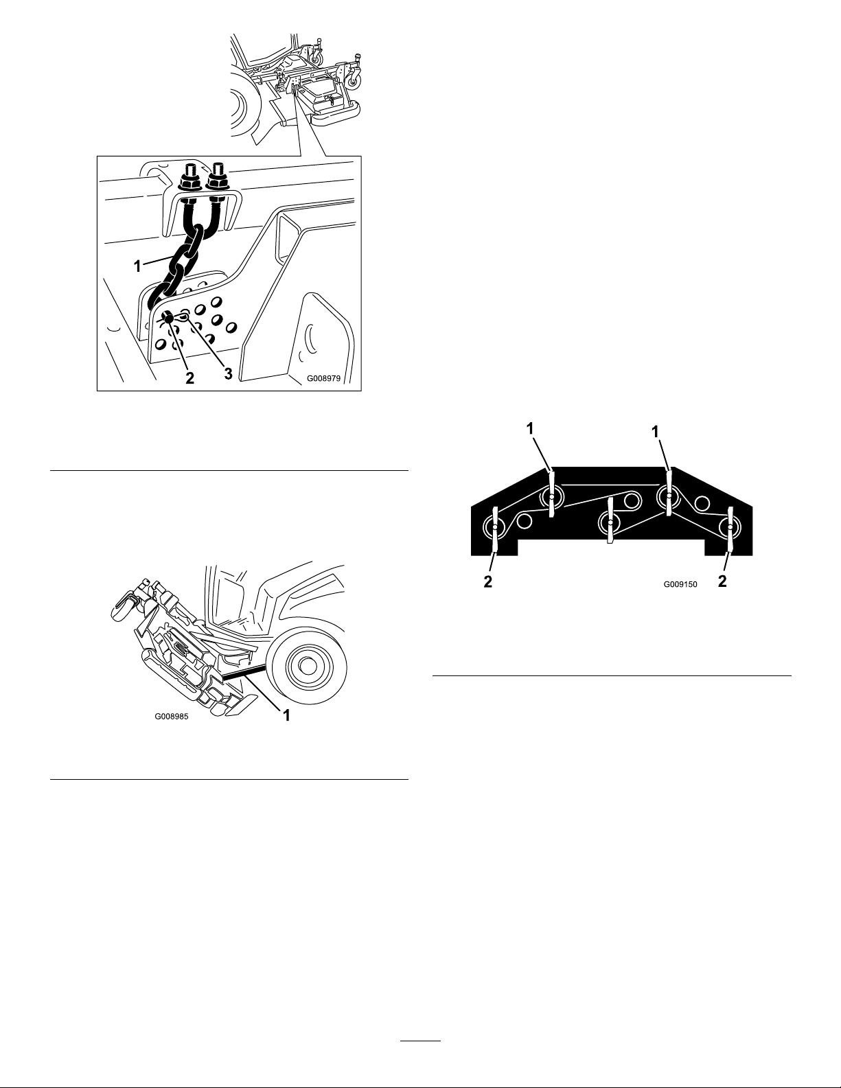
Figure92
AdjustingtheCuttingUnit Pitch
MeasuringtheCuttingUnitPitch
Cuttingunitpitchisthedifferenceinheight-of-cutfromthe
frontofthebladeplanetothebackofthebladeplane.T oro
recommendsabladepitchof7.5mm(.300inch).Thatisthe
backofthebladeplaneis7.5mm(.300inch)higherthan
thefront.
1.Positionthemachineonalevelsurfaceontheshop
oor.
2.Setthecuttingunittothedesiredheight-of-cut.
3.Makesurethewingletsareleveltothefrontdeckand
thefrontdeckislevelsidetoside.
AdjustingtheFrontCuttingUnit
1.Rotatethe2outerfrontbladesandthewingletblades
sothattheypointstraightforward(Figure94).
1.Heightofcutchain
2.Clevispin
4.Starttheengine,slowlyraisethefrontcuttingunit,and
stoptheengine.Removetheignitionkey.
5.Wedgea2x4betweentherearofthedeckandthe
machine(Figure93).
1.2x4
3.Hairpincotter
Figure93
PivotingtheFrontCuttingUnit Down
1.Withthehelpofanotherpersonholdingthefrontof
thecuttingunit,removethe2x4.
2.Sitontheseat,starttheengine,andlowerthecutting
unituntilitisslightlyoffoftheoor.
3.Securetheheight-of-cutchainstotherearofthe
cuttingunit.
4.Connectthedamperassemblyandsecureitwiththe
retainerclip.
Figure94
1.Useoneoftheseblades
formeasuringthefront
bladeheight
2.Usingashortruler,measurefromtheoortothefront
tipofthefrontbladeandrecordthisdimension.
3.Measurefromtheoortothebacktipofthewinglet
bladeandrecordthisdimension.
4.Subtractthefrontdimensionfromthereardimension
tocalculatethebladepitch.
5.Loosenthejamnutsonthetoporbottomofthe
height-of-cutchainU-bolt(Figure95).
Note:Loosenortightentheheightofcutchainnuts
equallysothedeckremainslevelsidetoside.
6.Adjusttheothersetofnutstoraiseorlowertherearof
thecuttingunitandattainthecorrectcuttingunitpitch.
7.Tightenthejamnuts.
2.Useoneoftheseblades
formeasuringtherear
bladeheight
58
Page 59

Figure95
1.Height-of-cutchain3.Nut(2)
2.U-bolt
ServicingtheCastorArm Bushings
Thecastorarmshavebushingspressedintothetopand
bottomofthetubeandaftermanyhoursofoperation,the
bushingswillwear.Tocheckthebushings,movethecastor
forkbackandforthandfromsidetoside.Ifthecastor
spindleislooseinsidethebushings,thebushingsareworn
andmustbereplaced.
1.Raisethecuttingunitsothatthewheelsareoffof
theoor.Blockthecuttingunitsothatitcannot
accidentallyfall.
2.Removethetensioningcap,spacer(s),andthrust
washerfromthetopofthecastorspindle.
Note:Recordthepositionofthewashersandspacers
beforeremovalsothedeckpitchdoesnothavetobe
readjusted.
3.Pullthecastorspindleoutofthemountingtube.
Allowthethrustwasherandspacer(s)toremainon
thebottomofthespindle.
4.Insertapinpunchintothetoporbottomofthe
mountingtubeanddrivethebushingoutofthetube
(Figure97).Alsodrivetheotherbushingoutofthe
tube.Cleantheinsideofthetubestoremovedirt.
AdjustingtheSideCuttingUnits
1.Removethetensioningcapfromthecastorspindle
shaftandslidethespindleoutofthecastorarm(Figure
96).Repositiontheshims,asrequired,toraiseorlower
thecastorwheeluntilthecuttingunithasthecorrect
pitch.
2.Installthetensioningcap.
Figure96
1.Tensioningcap4.Topaxlemountinghole
2.Spacers5.Castorwheel
3.Shims
Figure97
1.Castorarmtube
5.Applygreasetotheinsideandoutsideofthenew
bushings.Usingahammerandatplate,drivethe
bushingsintothemountingtube.
6.Inspectthecastorspindleforwearandreplaceitifit
isdamaged.
7.Pushthecastorspindlethroughthebushingsand
mountingtube.Slidethethrustwasherandspacer(s)
ontothespindle.Installthetensioningcaponthe
castorspindletoretainallpartsinplace.
2.Bushings
ServicingtheCastorWheels andBearings
ServiceInterval:Every500hours—Inspectthecuttingunit
castorwheelassemblies.
1.Removethelocknutfromtheboltholdingthecastor
wheelassemblybetweenthecastorfork(Figure98)or
59
Page 60

thecastorpivotarm.Graspthecastorwheelandslide
theboltoutoftheforkorpivotarm.
Figure98
1.Castorwheel
2.Castorfork
3.Bearing
4.Bearingspacer
BladeMaintenance
CheckingforaBentBlade
Afterstrikingaforeignobject,inspectthemachinefor
damageandmakerepairsbeforerestartingandoperatingthe
equipment.Torqueallthespindlepulleynutsto176to203
N⋅m(130to150ft-lb).
1.Positionthemachineonalevelsurface.Raisethe
cuttingunit,engagetheparkingbrake,putthetraction
pedalinneutral,makesurethePTOswitchisintheOff
position,stoptheengine,andremovetheignitionkey.
Blockthecuttingunittopreventitfromaccidentally
falling.
2.Rotatethebladeuntiltheendsfaceforwardand
backward(Figure99).Measurefromtheinsideof
thecuttingunittothecuttingedgeatthefrontofthe
blade.Recordthisdimension.
2.Removethebearingfromthewheelhubandallow
thebearingspacertofallout(Figure98).Removethe
bearingfromtheoppositesideofthewheelhub.
3.Checkthebearings,spacer,andinsideofthewheelhub
forwear.Replaceanydamagedparts.
4.Toassemblethecastorwheel,pushthebearingintothe
wheelhub.Wheninstallingthebearings,pressonthe
outerraceofthebearing.
5.Slidethebearingspacerintothewheelhub.Pushthe
otherbearingintotheopenendofthewheelhubto
captivatethebearingspacerinsidethewheelhub.
6.Installthecastorwheelassemblybetweenthecastor
forkandsecureitinplacewiththeboltandlocknut.
Figure99
3.Rotatetheoppositeendofthebladeforward.Measure
betweenthecuttingunitandcuttingedgeoftheblade
atthesamepositionasinstep2.Thedifference
betweenthedimensionsobtainedinsteps2and3
mustnotexceed3mm(1/8inch).Ifthedimension
exceeds3mm(1/8inch),thebladeisbentandmustbe
replaced;refertoRemovingandInstallingtheCutter
Blade.
RemovingandInstallingthe CutterBlade(s)
Theblademustbereplacedifasolidobjectishit,theblade
isoutofbalance,orifthebladeisbent.Alwaysusegenuine
Tororeplacementbladestobesureofsafetyandoptimum
performance.Neverusereplacementbladesmadebyother
manufacturersbecausetheycouldbedangerous.
1.Raisethecuttingunittothehighestposition,engage
theparkingbrake,stoptheengine,andremovethe
ignitionkey.Blockthecuttingunittopreventitfrom
accidentallyfalling.
2.Grasptheendofthebladeusingaragorthickly
paddedglove.Removethebladebolt,anti-scalpcup,
andbladefromthespindleshaft(Figure100).
3.Installtheblade,anti-scalpcup,andbladebolt.Tighten
thebladeboltto115to149N⋅m(85to110ft-lb).
Important:Thecurvedpartoftheblademustbe
pointingtowardtheinsideofthecuttingunitto
ensurepropercutting .
60
Page 61

Note:Afterstrikingaforeignobject,torqueallthe
spindlepulleynutsto176to203N⋅m(130to150ft-lb)
andthebladeboltsto115to149N⋅m(85to110ft-lb).
Figure100
1.Bladebolt2.Anti-scalpcup
2.Examinethecuttingendsofthebladecarefully,
especiallywheretheatandcurvedpartsoftheblade
meet(Figure97).Sincesandandabrasivematerialcan
wearawaythemetalthatconnectstheatandcurved
partsoftheblade,checkthebladebeforeusingthe
mower.Ifwearisnoticed(Figure97),replacetheblade.
Figure101
InspectingandSharpeningthe CutterBlade(s)
ServiceInterval:Aftertherst10hours
Every50hours
Beforeeachuseordaily
DANGER
Awornordamagedbladecanbreak,andapiece
ofthebladecouldbethrownintotheoperator's
orbystander'sarea,resultinginseriouspersonal
injuryordeath.Tryingtorepairadamagedblade
mayresultindiscontinuedsafetycerticationof
theproduct.
•Inspectthebladeperiodicallyforwearor
damage.
•Nevertrytostraightenabladethatisbentor
weldabrokenorcrackedblade
•Replaceawornordamagedblade.
Twoareasmustbeconsideredwhencheckingandservicing
thecutterblade-thesailandthecuttingedge.Bothcutting
edgesandthesail,whichistheturnedupportionopposite
thecuttingedge,contributetoagoodquality-of-cut.The
sailisimportantbecauseitliftsthegrassupstraight,thereby
producinganevencut.However,thesailwillgraduallywear
downduringoperation,andthisconditionisnormal.Asthe
sailwearsdown,thequality-of-cutwilldegradesomewhat,
althoughthecuttingedgesaresharp.Thecuttingedgeof
theblademustbesharpsothatthegrassiscutratherthan
torn.Adullcuttingedgeisevidentwhenthetipsofthegrass
appearbrownandshredded.Sharpenthecuttingedgesto
correctthiscondition.
1.CuttingEdge3.Wear/slotForming
2.CurvedArea4.Crack
3.Examinethecuttingedgesofalloftheblades.Sharpen
thecuttingedgesiftheyaredullornicked.Sharpen
onlythetopofthecuttingedgeandmaintainthe
originalcuttingangletomakesureofsharpness(Figure
97).Thebladewillremainbalancedifthesameamount
ofmetalisremovedfrombothcuttingedges.
DANGER
Ifthebladeisallowedtowear,aslotwillform
betweenthesailandatpartoftheblade
(Figure102).Eventuallyapieceoftheblade
maybreakoffandbethrownfromunderthe
housing,possiblyresultinginseriousinjury
toyouorbystanders.
•Inspectthebladeperiodicallyforwearor
damage.
•Nevertrytostraightenabladethatisbent
orweldabrokenorcrackedblade.
•Replaceawornordamagedblade.
Figure102
1.Sharpenatoriginalangle
1.Positionthemachineonalevelsurface.Raisethe
cuttingunit,engagetheparkingbrake,putthetraction
pedalinneutral,makesurethePTOswitchisintheOff
position,stoptheengine,andremovetheignitionkey.
Note:Removethebladesandsharpenthemonagrinder.
Aftersharpeningthecuttingedges,installthebladewith
theanti-scalpcupandbladebolt;refertoRemovingand
InstallingtheCutterBlade(s).
61
Page 62

CorrectingtheCuttingUnit
Miscellaneous
Mismatch
Ifthereismismatchbetweentheblades,onasinglecutting
unit,thegrasswillappearstreakedwhenitiscut.This
problemcanbecorrectedbymakingsurethatthebladesare
straight.
1.Usinga1meter(3foot)longcarpenterslevel,nda
levelsurfaceontheshopoor.
2.Raisetheheight-of-cuttothehighestposition;referto
AdjustingtheHeight-Of-Cut.
3.Lowerthecuttingunitontotheatsurface.Remove
thecoversfromthetopofthecuttingunit.
4.Rotatethebladesuntiltheendsfaceforwardand
backward.Measurefromtheoortothefronttipof
thecuttingedge.Recordthisdimension.Thenrotate
thesamebladesothattheoppositeendisforward,and
measureagain.Thedifferencebetweenthedimensions
mustnotexceed3mm(1/8inch).Ifthedimension
exceeds3mm(1/8inch),replacethebladebecauseit
isbent.Makesuretomeasurealloftheblades.
5.Checkthatdeckislevelsidetosideandadjustas
required.
6.Installthebeltcovers.
Maintenance
ServicingtheSparkArrestor
Mufer
ServiceInterval:Every250hours—Servicethespark
arrestor.
Every250hoursoperation,clearthemuferofcarbon
buildup.
1.Removethepipeplugfromtheclean-outportatthe
lowersideofthemufer.
CAUTION
Themufermaybehotandcouldcause
injury.
Becarefulwhileworkingaroundthemufer.
2.Starttheengine.Plugthenormalmuferexitwitha
blockofwoodormetalplatesothattheexhaustow
willbeforcedoutoftheclean-outport.Continueto
blocktheexituntilcarbondepositsceasecomingout
oftheport.
CAUTION
Donotstandinlinewiththeclean-outport.
Alwayswearsafetyglasses.
3.Stoptheengineandreplacethepipeplug.
CleaningtheCabAirFilters (For31599NModels)
ServiceInterval:Every250hours(Replacethemiftheyare
tornorexcessivelydirty.)
1.Removethescrewsandgratesfromoverboththe
in-cabandrearcabairlters(Figure103).
62
Page 63

1
2
3
g028378
Figure103
1
2
2
3
g028379
1
1
2
2
g028380
1
2
3
g028378
1.Stoptheengineandremovethekey.
2.Removethe6nutsandwashersfromthebottomofthe
rearofthecab(Figure105).
1.Filter
2.Grate
Figure104
1.Filter
2.Grate
2.Cleantheltersbyblowingclean,oilfree,compressed
airthroughthem.
Important:Ifeitherlterhasahole,tear,orother
3.Screw
3.Screw
damage,replaceit.
3.Installtheltersandgrate,securingthemwiththe
thumbscrews.
Figure105
1.Washer2.Nut
3.Removethecabinroofofthecabbyremovingthe22
boltsthatsecuretheroof(Figure106).
Figure106
1.Cabinroof
2.Airlters
3.Airconditioningcoils
4.Removetheairlters(Figure106).
CleaningtheAirConditioning
5.Removeandcleantheairconditioningcoils(Figure
Coil
ServiceInterval:Every250hours(Cleanmorefrequentlyin
extremelydustyordirtyconditions)
63
106).
6.Replacetheairconditioningcoils,airltersandcabin
roof.
Page 64

Storage
PreparingforSeasonal Storage
TractionUnit
1.Thoroughlycleanthetractionunit,cuttingunits,and
theengine.
Important:Donotusehighpressurewaternear
InfoCenter
2.Checkthetirepressure;refertoCheckingtheTire
PressureprocedureinOperation.
3.Checkallfastenersforlooseness;tightenasnecessary.
4.Greaseoroilallgreasettingsandpivotpoints.Wipe
upanyexcesslubricant.
5.Lightlysandandusetouch-uppaintonpaintedareas
thatarescratched,chipped,orrusted.Repairanydents
inthemetalbody.
6.Servicethebatteryandcablesasfollows:
A.Removethebatteryterminalsfromthebattery
posts.
B.Cleanthebattery,terminals,andpostswithawire
brushandbakingsodasolution.
C.Coatthecableterminalsandbatterypostswith
Grafo112Xskin-overgrease(T oroPartNo.
505-47)orpetroleumjellytopreventcorrosion.
D.Slowlyrechargethebatteryevery60daysfor24
hourstopreventleadsulfationofthebattery.
Engine
1.Draintheengineoilfromtheoilpanandinstallthe
drainplug.
2.Removeanddiscardtheoillter.Installanewoillter.
3.Relltheoilpanwith8.04liters(8.5quarts)ofSAE
15W-40CH-4,CI-4orhighermotoroil.
4.Starttheengineandrunitatidlespeedfor
approximatelytwominutes.
5.Stoptheengine.
6.Flushthefueltankwithfresh,cleandieselfuel.
7.Secureallofthefuelsystemttings.
8.Thoroughlycleanandservicetheaircleanerassembly.
9.Sealtheaircleanerinletandtheexhaustoutletwith
weatherprooftape.
10.Checktheantifreezeprotectionandadda50/50
solutionofwaterandethyleneglycolanti-freezeas
neededfortheexpectedminimumtemperatureinyour
area.
64
Page 65

Notes:
65
Page 66

Notes:
66
Page 67

Notes:
67
Page 68

ToroGeneralCommercialProductWarranty
ATwo-YearLimitedWarranty
ConditionsandProductsCovered
TheToroCompanyanditsafliate,T oroWarrantyCompany,pursuant
toanagreementbetweenthem,jointlywarrantyourT oroCommercial
product(“Product”)tobefreefromdefectsinmaterialsorworkmanship
fortwoyearsor1500operationalhours*,whicheveroccursrst.This
warrantyisapplicabletoallproductswiththeexceptionofAerators
(refertoseparatewarrantystatementsfortheseproducts).Wherea
warrantableconditionexists,wewillrepairtheProductatnocosttoyou
includingdiagnostics,labor,parts,andtransportation.Thiswarranty
beginsonthedatetheProductisdeliveredtotheoriginalretailpurchaser.
*Productequippedwithanhourmeter.
InstructionsforObtainingWarrantyService
YouareresponsiblefornotifyingtheCommercialProductsDistributoror
AuthorizedCommercialProductsDealerfromwhomyoupurchasedthe
Productassoonasyoubelieveawarrantableconditionexists.Ifyouneed
helplocatingaCommercialProductsDistributororAuthorizedDealer,or
ifyouhavequestionsregardingyourwarrantyrightsorresponsibilities,
youmaycontactusat:
ToroCommercialProductsServiceDepartment
ToroWarrantyCompany
811 1LyndaleAvenueSouth
Bloomington,MN55420-1196
952–888–8801or800–952–2740
E-mail:commercial.warranty@toro.com
OwnerResponsibilities
AstheProductowner,youareresponsibleforrequiredmaintenanceand
adjustmentsstatedinyourOperator'sManual.Failuretoperformrequired
maintenanceandadjustmentscanbegroundsfordisallowingawarranty
claim.
ItemsandConditionsNotCovered
Notallproductfailuresormalfunctionsthatoccurduringthewarranty
periodaredefectsinmaterialsorworkmanship.Thiswarrantydoesnot
coverthefollowing:
•Productfailureswhichresultfromtheuseofnon-T ororeplacement
parts,orfrominstallationanduseofadd-on,ormodiednon-Toro
brandedaccessoriesandproducts.Aseparatewarrantymaybe
providedbythemanufactureroftheseitems.
•Productfailureswhichresultfromfailuretoperformrecommended
maintenanceand/oradjustments.Failuretoproperlymaintainyour
ToroproductpertheRecommendedMaintenancelistedinthe
Operator’sManualcanresultinclaimsforwarrantybeingdenied.
•ProductfailureswhichresultfromoperatingtheProductinanabusive,
negligent,orrecklessmanner.
•Partssubjecttoconsumptionthroughuseunlessfoundtobedefective.
Examplesofpartswhichareconsumed,orusedup,duringnormal
Productoperationinclude,butarenotlimitedto,brakepadsand
linings,clutchlinings,blades,reels,rollersandbearings(sealedor
greasable),bedknives,sparkplugs,castorwheelsandbearings,tires,
lters,belts,andcertainsprayercomponentssuchasdiaphragms,
nozzles,andcheckvalves,etc.
•Failurescausedbyoutsideinuence.Conditionsconsideredtobe
outsideinuenceinclude,butarenotlimitedto,weather,storage
practices,contamination,useofunapprovedfuels,coolants,lubricants,
additives,fertilizers,water,orchemicals,etc.
•Failureorperformanceissuesduetotheuseoffuels(e.g.gasoline,
diesel,orbiodiesel)thatdonotconformtotheirrespectiveindustry
standards.
•Normalnoise,vibration,wearandtear ,anddeterioration.
•Normal“wearandtear”includes,butisnotlimitedto,damagetoseats
duetowearorabrasion,wornpaintedsurfaces,scratcheddecalsor
windows,etc.
Parts
Partsscheduledforreplacementasrequiredmaintenancearewarranted
fortheperiodoftimeuptothescheduledreplacementtimeforthatpart.
Partsreplacedunderthiswarrantyarecoveredforthedurationofthe
originalproductwarrantyandbecomethepropertyofT oro.T orowillmake
thenaldecisionwhethertorepairanyexistingpartorassemblyorreplace
it.T oromayuseremanufacturedpartsforwarrantyrepairs.
DeepCycleandLithium-IonBatteryWarranty:
DeepcycleandLithium-Ionbatterieshaveaspeciedtotalnumberof
kilowatt-hourstheycandeliverduringtheirlifetime.Operating,recharging,
andmaintenancetechniquescanextendorreducetotalbatterylife.Asthe
batteriesinthisproductareconsumed,theamountofusefulworkbetween
chargingintervalswillslowlydecreaseuntilthebatteryiscompletelyworn
out.Replacementofwornoutbatteries,duetonormalconsumption,
istheresponsibilityoftheproductowner.Batteryreplacementmaybe
requiredduringthenormalproductwarrantyperiodatowner’sexpense.
Note:(Lithium-Ionbatteryonly):ALithium-Ionbatteryhasapartonly
proratedwarrantybeginningyear3throughyear5basedonthetime
inserviceandkilowatthoursused.RefertotheOperator'sManualfor
additionalinformation.
MaintenanceisatOwner’sExpense
Enginetune-up,lubrication,cleaningandpolishing,replacementoflters,
coolant,andcompletingrecommendedmaintenancearesomeofthe
normalservicesT oroproductsrequirethatareattheowner’sexpense.
GeneralConditions
RepairbyanAuthorizedToroDistributororDealerisyoursoleremedy
underthiswarranty.
NeitherTheToroCompanynorToroWarrantyCompanyisliablefor
indirect,incidentalorconsequentialdamagesinconnectionwiththe
useoftheToroProductscoveredbythiswarranty,includingany
costorexpenseofprovidingsubstituteequipmentorserviceduring
reasonableperiodsofmalfunctionornon-usependingcompletion
ofrepairsunderthiswarranty.ExceptfortheEmissionswarranty
referencedbelow,ifapplicable,thereisnootherexpresswarranty.All
impliedwarrantiesofmerchantabilityandtnessforusearelimitedto
thedurationofthisexpresswarranty.
Somestatesdonotallowexclusionsofincidentalorconsequential
damages,orlimitationsonhowlonganimpliedwarrantylasts,sotheabove
exclusionsandlimitationsmaynotapplytoyou.Thiswarrantygivesyou
speciclegalrights,andyoumayalsohaveotherrightswhichvaryfrom
statetostate.
Noteregardingenginewarranty:
TheEmissionsControlSystemonyourProductmaybecoveredby
aseparatewarrantymeetingrequirementsestablishedbytheU.S.
EnvironmentalProtectionAgency(EP A)and/ortheCaliforniaAirResources
Board(CARB).Thehourlimitationssetforthabovedonotapplytothe
EmissionsControlSystemWarranty.RefertotheEngineEmissionControl
WarrantyStatementsuppliedwithyourproductorcontainedintheengine
manufacturer’sdocumentationfordetails
CountriesOtherthantheUnitedStatesorCanada
CustomerswhohavepurchasedT oroproductsexportedfromtheUnitedStatesorCanadashouldcontacttheirT oroDistributor(Dealer)toobtain
guaranteepoliciesforyourcountry ,province,orstate.IfforanyreasonyouaredissatisedwithyourDistributor'sserviceorhavedifcultyobtaining
guaranteeinformation,contacttheT oroimporter.
374-0253RevC
 Loading...