

Page 1

FormNo.3403-609RevA
Groundsmaster
®
5900or5910
RotaryMower
ModelNo.31598—SerialNo.316000001andUp
ModelNo.31598N—SerialNo.316000001andUp
ModelNo.31599—SerialNo.316000001andUp
ModelNo.31599N—SerialNo.316000001andUp
Registeratwww.T oro.com.
OriginalInstructions(EN)
*3403-609*A
Page 2

WARNING
CALIFORNIA
Proposition65Warning
Thisproductcontainsachemicalorchemicals
knowntotheStateofCaliforniatocausecancer,
birthdefects,orreproductiveharm.
Dieselengineexhaustandsomeofits
constituentsareknowntotheStateof
Californiatocausecancer,birthdefects,
andotherreproductiveharm.
ItisaviolationofCaliforniaPublicResourceCode
Section4442or4443touseoroperatetheengineonany
forest-covered,brush-covered,orgrass-coveredlandunless
theengineisequippedwithasparkarrester,asdenedin
Section4442,maintainedineffectiveworkingorderorthe
engineisconstructed,equipped,andmaintainedforthe
preventionofre.
Theenclosed
Engine Owner's Man ual
issuppliedfor
informationregardingtheUSEnvironmentalProtection
Agency(EPA)andtheCaliforniaEmissionControl
Regulationofemissionsystems,maintenance,and
warranty.Replacementsmaybeorderedthroughthe
enginemanufacturer.
Introduction
Thismachineisaride-on,rotary-bladelawnmowerintended
tobeusedbyprofessional,hiredoperatorsincommercial
applications.Itisprimarilydesignedforcuttinggrasson
well-maintainedlawnsinparks,golfcourses,sportselds,
andoncommercialgrounds.Itisnotdesignedforcutting
brush,mowinggrassandothergrowthalongsidehighways,
orforagriculturaluses.
Readthisinformationcarefullytolearnhowtooperateand
maintainyourproductproperlyandtoavoidinjuryand
productdamage.Youareresponsibleforoperatingthe
productproperlyandsafely.
YoumaycontactTorodirectlyatwww .Toro.comforproduct
safetyandoperationtrainingmaterials,accessoryinformation,
helpndingadealer,ortoregisteryourproduct.
Wheneveryouneedservice,genuineT oroparts,oradditional
information,contactanAuthorizedServiceDealerorToro
CustomerServiceandhavethemodelandserialnumbersof
yourproductready.Figure1identiesthelocationofthe
modelandserialnumbersontheproduct.Writethenumbers
inthespaceprovided.
Figure1
1.Modelandserialnumberlocation
ModelNo.
SerialNo.
Thismanualidentiespotentialhazardsandhassafety
messagesidentiedbythesafety-alertsymbol(Figure2),
whichsignalsahazardthatmaycauseseriousinjuryordeath
ifyoudonotfollowtherecommendedprecautions.
Figure2
1.Safety-alertsymbol
Thismanualuses2wordstohighlightinformation.
Importantcallsattentiontospecialmechanicalinformation
andNoteemphasizesgeneralinformationworthyofspecial
attention.
©2016—TheToro®Company
8111LyndaleAvenueSouth
Bloomington,MN55420
Contactusatwww.Toro.com.
2
PrintedintheUSA
AllRightsReserved
Page 3

Contents
Safety...........................................................................4
GeneralSafety.........................................................4
SafetyandInstructionalDecals.................................5
Setup...........................................................................13
1RemovingtheSide-DeckShippingStrapand
Brace................................................................13
2LoweringtheFront-DeckWinglets.........................14
3LevelingtheFront,CenterDeck.............................15
4LevelingtheWingletDeckstotheFront,Center
Deck.................................................................15
5PreparingtheMachine..........................................16
ProductOverview.........................................................16
Controls...............................................................16
CabControls......................................................18
Specications........................................................23
Attachments/Accessories........................................23
BeforeOperation......................................................23
BeforeOperationSafety..........................................23
CheckingtheEngine-OilLevel.................................24
CheckingtheCoolingSystem...................................24
CheckingtheHydraulicSystem................................24
FillingtheFuelTank...............................................24
CheckingtheTirePressure......................................25
CheckingtheTorqueoftheWheel-Lug
Nuts.................................................................25
AdjustingtheHeightofCut.....................................26
AdjustingtheSkids.................................................28
AdjustingtheMowerDeckAnti-Scalp
Rollers...............................................................28
CheckingaMismatchBetweenMower
Decks................................................................29
AdjustingtheMirrors..............................................30
AimingtheHeadlights............................................30
CheckingtheSafety-InterlockSwitches......................31
DuringOperation.....................................................31
DuringOperationSafety.........................................31
StartingandStoppingtheEngine..............................32
UnderstandingtheOperatingCharacteristics..............33
AutomaticReversing-FanCycle................................33
OperatingTips......................................................33
AfterOperation........................................................34
AfterOperationSafety............................................34
IdentifyingtheTie-DownPoints..............................35
PushingorTowingtheMachine................................35
Maintenance.................................................................36
RecommendedMaintenanceSchedule(s)......................36
ServiceIntervalChart.............................................37
PremaintenanceProcedures........................................37
Pre-MaintenanceSafety...........................................37
PreparingtheMachineforMaintenance.....................38
RaisingtheMachine................................................38
RemovingandInstallingtheInner-Wing-Deck
Covers...............................................................38
Lubrication...............................................................39
GreasingtheBearingsandBushings..........................39
EngineMaintenance..................................................42
EngineSafety.........................................................42
Air-CleanerMaintenance.........................................42
ServicingtheEngineOil..........................................43
AdjustingtheValveClearance..................................44
FuelSystemMaintenance...........................................44
ServicingtheFuelSystem........................................44
ServicingtheWaterSeparator..................................45
ReplacingtheFuelFilter..........................................45
ElectricalSystemMaintenance....................................46
ElectricalSystemSafety...........................................46
LocatingtheFuses..................................................46
CheckingtheBatteryCondition................................47
ChargingtheBattery...............................................48
UsingtheAlternatePositivePost..............................48
CalibratingtheTractionPedal..................................48
DriveSystemMaintenance.........................................49
AdjustingtheTraction-PedalAngle...........................49
CheckingthePlanetary-DriveGear/Brake-Oil
Level.................................................................49
ChangingthePlanetary-DriveGear/Brake
Oil....................................................................49
CheckingtheRear-WheelToe-in...............................50
CoolingSystemMaintenance......................................51
CoolingSystemSafety.............................................51
CheckingtheCoolingSystem...................................51
ServicingtheEngine-CoolingSystem........................52
BrakeMaintenance....................................................52
AdjustingtheServiceBrakes....................................52
BeltMaintenance......................................................53
ServicingtheAlternatorBelt....................................53
ServicingtheCompressorBelt.................................53
ReplacingtheBlade-DriveBelts................................53
HydraulicSystemMaintenance....................................55
HydraulicSystemSafety..........................................55
CheckingtheHydraulicFluid...................................55
ChangingtheHydraulicFluidandFilters....................56
CheckingtheHydraulicLinesandHoses....................57
InspectingtheHydraulic-SystemTestPorts................57
MowerMaintenance...................................................57
Pivoting(Tilting)theFrontMowerDeck
Upright.............................................................57
Pivoting(Tilting)theFrontMowerDeck
Down................................................................58
AdjustingtheMower-DeckPitch..............................58
ServicingtheCastor-ArmBushings...........................59
ServicingtheCasterWheelsandBearings...................60
BladeMaintenance.....................................................60
BladeSafety...........................................................60
CheckingforaBentBlade........................................60
RemovingandInstallingaBlade...............................61
InspectingandSharpeningtheCutterBlade(s)............61
CorrectingaMower-DeckMismatch.........................62
MiscellaneousMaintenance.........................................62
ServicingtheSpark-ArrestorMufer.........................62
CleaningtheCabAirFilters.....................................63
CleaningtheAir-ConditioningAssembly
........................................................................63
Cleaning...................................................................64
3
Page 4

CleaningtheCab....................................................64
DisposingofWaste.................................................64
Storage........................................................................64
PreparingforSeasonalStorage.................................64
Safety
ThismachinehasbeendesignedinaccordancewithANSI
B71.4-2012.
GeneralSafety
Thisproductiscapableofamputatinghandsandfeetand
ofthrowingobjects.Alwaysfollowallsafetyinstructionsto
avoidseriouspersonalinjury.
Usingthisproductforpurposesotherthanitsintendeduse
couldprovedangeroustoyouandbystanders.
•ReadandunderstandthecontentsofthisOperator’ sManual
beforeyoustarttheengine.Ensurethateveryoneusing
thisproductknowshowtouseitandunderstandsthe
warnings.
•Donotputyourhandsorfeetnearmovingcomponents
ofthemachine.
•Donotoperatethemachinewithoutallguardsandother
safetyprotectivedevicesinplaceandworkingonthe
machine.
•Keepclearofanydischargeopening.Keepbystandersa
safedistancefromthemachine.
•Keepchildrenoutoftheoperatingarea.Neverallow
childrentooperatethemachine.
•Stopthemachineandshutofftheenginebeforeservicing,
fueling,oruncloggingthemachine.
Improperlyusingormaintainingthismachinecanresult
ininjury.Toreducethepotentialforinjury,complywith
thesesafetyinstructionsandalwayspayattentiontothe
safety-alertsymbol,whichmeansCaution,Warning,or
Danger—personalsafetyinstruction.Failuretocomplywith
theseinstructionsmayresultinpersonalinjuryordeath.
Youcanndadditionalitemsofsafetyinformationintheir
respectivesectionsthroughoutthismanual.
4
Page 5

SafetyandInstructionalDecals
Safetydecalsandinstructionsareeasilyvisibletotheoperatorandarelocatednearanyareaofpotential
danger.Replaceanydecalthatisdamagedorlost.
93-6674
1.Crushinghazard,hand—readtheinstructionsbefore
servicingorperformingmaintenance.
93-6686
1.Hydraulicoil
2.ReadtheOperator'sManual.
93-6687
1.Donotstephere.
106-6754
1.Warning—donottouchthehotsurface.
2.Cutting/dismembermenthazard,fanandentanglement
hazard,belt—stayawayfrommovingparts.
106-6755
1.Enginecoolantunder
pressure.
2.Explosionhazard—read
theOperator'sManual.
3.Warning—donottouchthe
hotsurface.
4.Warning—readthe
Operator'sManual.
93-7275
1.ReadtheOperator’sManual—donotusestartinguidto
starttheengine.
93-7818
1.Warning—readtheOperator'sManualforinstructionson
torquingthebladebolt/nutto1 15to149N·m(85to1 10
ft-lb).
1.Windshieldwipers—off
2.Windshieldwipers
5
125-9688
ModelwithCabOnly
3.Windshieldwipers—on
4.Spraywindshieldwasher
uid
Page 6

114-0135
132-3600
ModelwithCabOnly
1.ReadtheOperator's
Manualformore
informationonfuses.
2.Headlight—25A6.Auxiliarypower—15A
3.CondenserfanandA/C
clutch—30A
4.Fan—25A8.Windshieldwipers—15A
5.Workinglight—20A
7.Cablight—15A
1.Raisecuttingunits—left
2.Raisecutting
units—center
3.Raisecuttingunits—right
114-0133
1.Headlights7.Tractionassist—engage
2.On
3.Off9.Lowercuttingunits—left
4.Headlightswitchlocation10.Lowercutting
5.Cruisecontrol—engage
6.Cruisecontrol—disengage
8.Traction
assist—disengage
units—center
11.Lowercuttingunits—right
114-0844
1.Leftturnsignal
2.Rightturnsignal5.T ounlocktheparking
3.ReadtheOperators
Manual.
4.Tolockthebrakes,close
thelatch,pressthebrake
pedal,andpulluponthe
parking-brakeknob.
brake,pressthebrake.
6.Parkingbrake
114-0845
1.Tiltsteeringlever2.Horn
6
Page 7

114-0846
1.ReadtheOperatorsManual;tostarttheengine,movethe
tractionpedaltoNeutral,applythebrake,movethethrottle
switchtolow,turntheignitionkeytoPreheat.Whenthe
WaittoStartAdvisoryclearsontheInfoCenter,turnthe
ignitionkeytoStart.
2.ReadtheOperatorsManual;tostoptheengine,movethe
throttlelevertoslow,disengagethePTO,settheparking
brake,wait5minutes,turntheignitionkeytoStop,and
removethekey;readtheOperatorsManual.
3.ReadtheOperatorsManual.
4.ToengagethePTO,pulluponthePTOswitch.
5.TodisengagethePTO,pushdownonthePTOswitch.
6.Toswitchthetransmissiontohighspeed,fullyraisethe
attachmentsandswitchthespeedcontroltoHigh.
114-0848
1.Highrange6.Lowidle
2.Transmission7.Increaseenginespeed
3.Lowrange8.Engine
4.Highidle
5.Mididle10.Decreaseenginespeed
9.ReadtheOperator’s
Manual.
7
Page 8

114-0865
114-0922
1.Height-of-cutadjustment
114-0849
1.Warning—disengagethePTOthenraisethedeck.
2.Nostep
3.Tractioncontrolpedal
4.Forward
5.Reverse
114-0864
1.Height-of-cutadjustment
114-0922
1.Beltrouting
114-0974
1.Beltrouting
8
Page 9

1.Beltrouting
1.ReadtheOperator'sManual.
117-4979
1.Entanglementhazard,belt—stayawayfrommovingparts,
keepallguardsandshieldsinplace.
114-4883
114-9600
115-5459
1.Electricshockhazard—donotremovecover;keepcoverin
place.
130-0611
ModelwithCabOnly
1.Warning—1)Removethepin;2)Raisethedoors;3)Exit
thecab
120-6604
1.Thrownobjecthazard—keepbystandersawayfromthe
machine.
2.Cutting/dismembermenthazardofhand,mower
blade—stayawayfrommovingparts,keepallguardsand
shieldsinplace.
3.Cutting/dismembermenthazardoffoot,mowerblade—stay
awayfrommovingparts,keepallguardsandshieldsin
place.
121-3883
1.DisengagethePTO3.ReadtheOperator’s
117-2718
2.EngagethePTO
Manual
9
Page 10

BatterySymbols
Someorallofthesesymbolsareonyourbattery
1.Engine—stop3.Engine—start
2.Engine—preheat
1.Explosionhazard
2.Nore,opename,or
smoking.
121-3884
3.Causticliquid/chemical
burnhazard
4.Weareyeprotection.9.Flusheyesimmediately
5.ReadtheOperator's
Manual.
6.Keepbystandersasafe
distancefromthebattery.
7.Weareyeprotection;
explosivegasescan
causeblindnessandother
injuries.
8.Batteryacidcancause
blindnessorsevereburns.
withwaterandgetmedical
helpfast.
10.Containslead;donot
discard.
125-5263
1.ReadtheOperator’sManualforinformationonfuses.
10
Page 11

114-0975
1.Heightofcut
117-2754
1.Warning—readtheOperator'sManual.
2.Warning—donotoperatethismachineunlessyouaretrained.
3.Warning—weartheseatbeltwhenseatedintheoperator'sposition.
4.Warning—wearhearingprotection.
5.Thrownobjecthazard—keepbystandersasafedistancefromthemachine.
6.Cuttinghazardofhandorfoot—stayawayfrommovingparts;keepallguardsinplace.
7.Tippinghazard—lowerthecuttingunitwhendrivingdownslopes;slowthemachinebeforeturning,donotturnathighspeeds
8.Warning—locktheparkingbrake,stoptheengine,andremovetheignitionkeybeforeleavingthemachine.
11
Page 12

121-8378
ModelwithCabOnly
1.Fan—off3.Coldair
2.Fan—onfull
4.Hotair6.Internalair8.Airconditioner—on
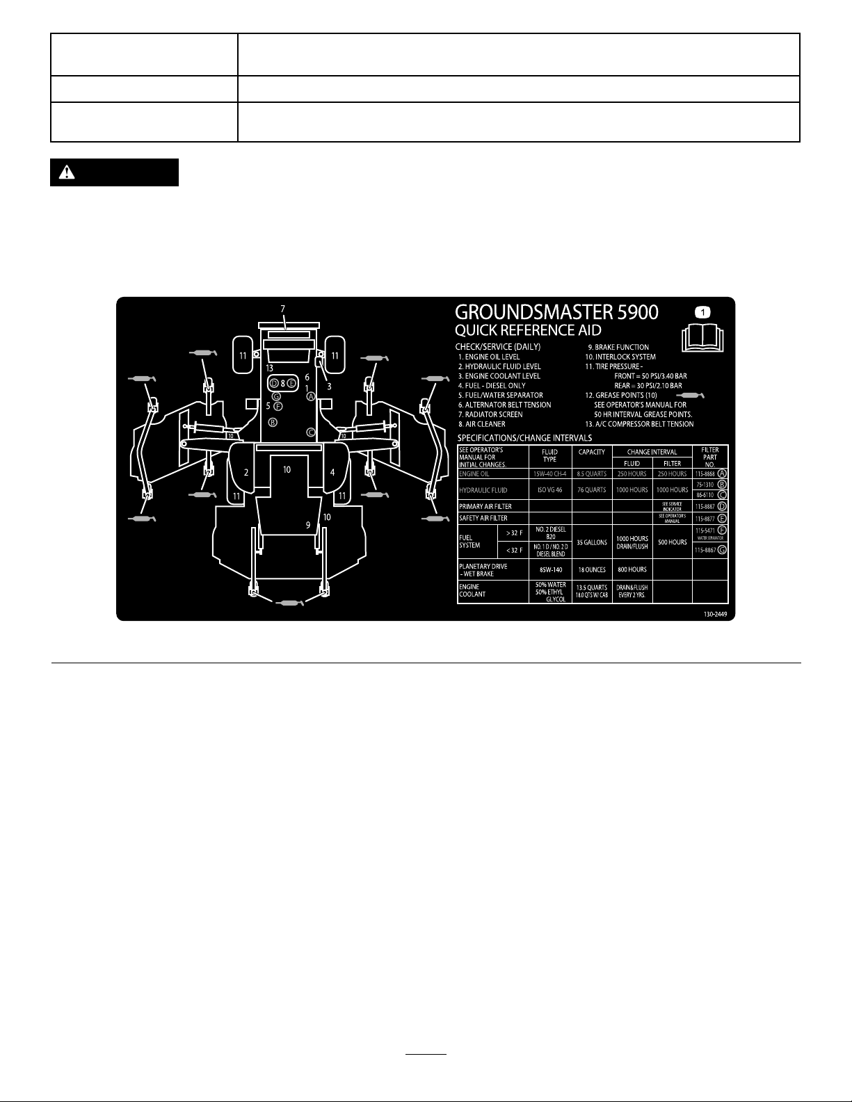
130-2449
5.Externalair
7.Airconditioner—off
1.ReadtheOperator’sManualforinformationonmaintenance.
12
Page 13

Setup
LooseParts
Usethechartbelowtoverifythatallpartshavebeenshipped.
ProcedureDescription
1
2
3
4
5
MediaandAdditionalParts
Description
Operator'sManual
EngineOwner'sManual
PartsCatalog
Nopartsrequired
Rightdeckcover1
Leftdeckcover
V-Belt2
Nopartsrequired
Nopartsrequired
Nopartsrequired
Qty.
1
1
1
Reviewitbeforeoperatingthemachine.
Useittoreferenceengineinformation.
Useittoreferencepartnumbersandorderreplacement
parts.
Qty.
Use
–
1
–
–
–
Removetheside-deckshippingstraps
andbrace.
Lowerthefrontdeckwinglets.
Levelthefront,centerdeck.
Levelthewingletdeckstothefront,
centerdeck.
Preparethemachine.
Use
Operatortrainingmaterials
Declarationofconformity
Note:Determinetheleftandrightsidesofthemachinefromthenormaloperatingposition.
Note:Somepartsmayhavealreadybeeninstalledatthefactory.
1
1
Readthematerialsbeforeoperatingthemachine.
ForCEcompliance
1
RemovingtheSide-Deck ShippingStrapandBrace
NoPartsRequired
Procedure
Removethestrapandbracesecuringthesidedecksfor
shipping.
13
Page 14

2
LoweringtheFront-Deck Winglets
Partsneededforthisprocedure:
1Rightdeckcover
1
Leftdeckcover
2V-Belt
Procedure
1.Removethenutssecuringthefrontandrearstopbolts
totherightwinglet-deckmounts(Figure3).
Figure4
1.Winglet4.Eccentric
2.Hingepin5.Lowerhole
3.Bolt
5.Installthenutssecuringthestopbolts.
Figure3
1.Winglet4.Eccentric
2.Hingepin5.Upperhole
3.Stopbolt
2.Whilesupportingtherightwinglet,removethefront
andrearstopboltsfromthedeckmounts(Figure3).
Note:Leavetheeccentricspositionedbetweenthe
deckmounts.
6.Deckmounts
Note:Donottightenthenutsatthistime.
6.Repeatthisprocedureonleftwinglet.
7.Installthewingletbeltsasfollows:
A.Startthebeltaroundthewinglet-spindlepulley
andthefront-deck-spindlepulley(Figure5).
Figure5
1.Winglet-spindlepulley3.Idlerpulley
2.Front-deck-spindlepulley
3.Lowerthewinglettotheoperatingposition.
4.Installthefrontandrearstopboltsthroughthe
upper-mountingholesandeccentrics(Figure4).
Note:Ensurethatthestopboltengagesthetabon
thehingepin.
B.Usingaratchetwrenchorasimilartool,movethe
idlerpulleyawayfromthepulleys(Figure5).
C.Routethebeltaroundthewinglet-spindlepulley
andtheupper-spindlepulleyonthefrontdeck.
D.Releasetheidlerpulleytoputtensiononthebelt.
14
Page 15

8.Installthewinglet-deckcoverandsecureitwiththe
rubberlatch(Figure6).
Note:Ensurethatyouslidethecoverunderthefront,
centerdeck-covertabsbeforeinsertingitontothe
mountinghooksandpost.
9.Repeatthisprocedureontheotherwinglet.
Figure6
1.Cover
2.Rubberlatch4.Mounthooks
3.Front,centerdeck-cover
tabs
4
LevelingtheWingletDecksto theFront,CenterDeck
NoPartsRequired
Procedure
1.Rotatethebladeoneachwingletsothatitpointsside
toside.
2.Loosentheboltsandnutssecuringthe2eccentric
spacerstothewinglets(Figure7).
3
LevelingtheFront,Center Deck
NoPartsRequired
Procedure
RefertoAdjustingtheHeightofCut(page26).
1.Rotatethebladeoneachouterspindleuntiltheends
faceforwardandbackward.
2.Measurefromtheoortothefronttipoftheblade.
3.Adjustthe1/8inchshimsonthefrontcasterfork(s)
tomatchthedesiredheightofcut.
4.Rotatetheblades180°andmeasurefromtheoorto
therear-facingtipoftheblade.
5.Loosenthelowerjamnutsontheheight-of-cutchain
U-bolt.
6.Adjustthenutstoraiseorlowertherearofthemower
decksothatthetipsofthefrontandrearbladeshave
thesamemeasurement.
Figure7
1.Winglet4.Eccentric
2.Hingepin5.Upperhole
3.Stopbolt
3.Rotatetherear(closesttothetractionunit)eccentric
untiltheoutsidebladetipisabout3mm(1/8inch)
higherthanthedesiredheightofcut(Figure7).
Note:Thereisanotchontheeccentrichex,whichis
180°fromthelobeontheeccentriccam(Figure8).
Usethenotchestoreferencethelocationofthelobes
whenadjustingtheeccentrics.
7.Tightenthejamnuts.
15
Page 16

Figure8
1.Eccentricnotch
4.Tightentheboltandnutforthiseccentricto149N·m
(110ft-lb).
5.Adjusttheforwardeccentricuntilitjustmakescontact
withtheinnerslotsurfaceofthewinglet-pivotbrackets.
ProductOverview
Controls
Note:Determinetheleftandrightsidesofthemachine
fromthenormaloperatingposition.
6.Tightentheboltandnutforthiseccentricto149N·m
(110ft-lb).
7.Repeattheprocedureontheoppositewinglet.
5
PreparingtheMachine
NoPartsRequired
CheckingtheTirePressure
Checkthetirepressurebeforeuse;refertoCheckingtheTire
Pressure(page25).
Important:Maintainpressureinalltirestoensurea
goodquality-of-cutandpropermachineperformance.
Do not underinate the tir es.
CheckingtheFluidLevels
1.Checktheengine-oillevelbeforestartingtheengine;
refertoCheckingtheEngine-OilLevel(page43).
2.Checkthehydraulic-uidlevelbeforestartingthe
engine;refertoCheckingtheHydraulicFluid(page55).
Figure9
1.Brakepedals7.Variablethrottleswitch
2.Pedal-lockinglatch8.Throttleswitch
3.Parking-brakelatch9.Horn
4.Turn-signalswitch10.Tractionpedal
5.Infocenter11.Steering-levertilt
6.High-Lowrange-speed
switch
TractionPedal
Thetractionpedalcontrolstheforwardandreverseoperation.
Pressthetopofthepedaltomovethemachineforwardand
thebottomtomoveitbackward.Groundspeeddependson
howfaryoupressthepedal.Fornoload,maximumground
speed,fullypressthepedalwhilethethrottleisintheHIGH
IDLEposition(Figure9).
Tostopthemachine,reduceyourfootpressureonthe
tractionpedalandallowittoreturntothecenterposition.
Pedal-LockingLatch
Thepedal-lockinglatchconnectsthepedalstogetherto
engagetheparkingbrake(Figure9).
3.Checkthecoolingsystembeforestartingtheengine;
refertoCheckingtheCoolingSystem(page51).
GreasingtheMachine
Greasethemachinebeforeuse;refertoLubrication(page39).
Failuretoproperlygreasethemachineresultsinpremature
failureofcriticalparts.
Parking-BrakeLatch
Theknobontheleftsideoftheconsoleactuatesthe
parking-brakelock.Toengagetheparkingbrake,connect
thepedalswiththepedal-lockinglatch,pushdownonboth
pedals,andpulltheparking-brakelatchout.Toreleasethe
parkingbrake,pressbothpedalsuntiltheparking-brakelatch
retracts(Figure9).
16
Page 17

Steering-LeverTilt
Presstheleverdowntotiltthesteeringwheeltothedesired
position.Releasethelevertolocktheadjustment(Figure9).
Turn-SignalSwitch
Presstheleftsideoftheturn-signalswitchtoactivatethe
left-turnsignalandtherightsideoftheswitchtoactivatethe
right-turnsignal(Figure9).
Note:Thecenterpositionisoff.
High-LowRangeSpeedSwitch
PressthefrontoftheswitchtoselectHIGH-SPEEDRANGE.
PresstherearoftheswitchtoselectLOW-SPEEDRANGE.The
machinemustbestationaryortravelingataveryslowspeed,
lessthan3.2km/h(2mph),toshifttoHIGH–LOW(Figure9).
HornButton
Pressthehornbuttontoactivatethehorn(Figure9).
ThrottleSwitch
Thethrottleswitchhas3positionsLOWIDLE,MIDIDLE,and
HIGHIDLE(Figure9).
Figure10
1.PTOswitch5.Cruisecontrol
2.Keyswitch6.Lightswitch
3.Traction-assistswitch
4.Liftswitches
7.Powerpoint(ontheright
sideofconsole)
LiftSwitches
Theliftswitchesraiseandlowerthemowerdecks(Figure10).
Presstheswitchesforwardtolowerthemowerdeckand
backwardtoraiseit.
Variable-ThrottleSwitch
Thevariable-throttleswitchallowstheenginespeedtobe
adjustedinsmallincrements.Pressthe“+”oncetoincrease
theenginespeedandthe“-”oncetodecreasetheengine
speed(Figure10).
Note:Movingthethrottleswitchoverridesandcancelsthe
variable-throttlesetting.
Important:Donotoperatetheenginebelow1350rpm.
KeySwitch
Thekeyswitch(Figure10)has3positions:STOP,
RUN/PREHEAT,andSTART.
Note:Thedecksdonotlowerwhilethemachineisinthe
HIGH-speedrange,andthedecksdonotraiseorlowerifyou
areoutoftheseatwhiletheengineisrunning.
LightSwitch
PressthelightswitchupwardtoturnthelightstotheON
position(Figure10).
Pressthelightswitchdownwardtoturnthelightstothe
OFFposition.
PTOSwitch
ThePTOswitchhas2positions:OUT(start)andIN(stop).
PulloutthePTObuttontoengagetheimplementor
mower-deckblades.Pushinthebuttontodisengagethe
implementoperation(Figure10).
Traction-AssistSwitch
Whenmowing(lowspeedrange),pressandholdthe
traction-assistswitchtoenhancethetraction-drive
performanceincompromisedoperatingconditions(Figure
10).
Note:ThetractionassistonlyengagesinMow-Forward.
ThetractionassistdoesnotengageinMow-ReverseorHigh
speedrange.
17
Page 18

Cruise-ControlSwitch
Windshield-WiperSwitch
Thecruise-controlswitchsetsyourdesiredspeedofthe
machine.
Presstheswitchforwardtoengagethecruisecontroland
rearwardtodisengageit(Figure10).
AudibleAlarm(Console)
Thealarmisactivatedwhenafaultisdetected.
Thebuzzersoundswhenthefollowingoccur:
•Whentheenginesendsastopfault
•Whentheenginesendsacheck-enginefault
•Whenthefuellevelislow
CabControls
Usethewindshield-wiperswitchtoturnthewindshield
wiperstotheONorOFFposition(Figure11).
LightsSwitch
Usethelightsswitchtoturntheheadlightsandtail-lightsto
theONorOFFposition(Figure10).
FlashersSwitch
Usetheashersswitchtoturntheashers(hazardlights)to
theONorOFFposition(Figure10).
Air-ConditioningSwitch
Usetheair-conditioningswitchtoturntheairconditioning
onoroff(Figure11).
WindshieldLatch
Liftupthelatchtoopenthewindshield(Figure12).Pressin
thelatchtolockthewindshieldintheopenposition.Pullout
anddownonthelatchtocloseandsecurethewindshield.
Figure11
1.Air-conditioningswitch4.Temperaturecontrol
2.Air-recirculationcontrol5.Windshield-wiperswitch
3.Fancontrol
Air-RecirculationControl
6.Blankswitchesforoptional
kits
Thiscontroleitherrecirculatestheairinthecabinordraws
outsideairintothecabin(Figure11).
•Setittorecirculatetheairwhenusingairconditioning.
•Setittodrawairinwhenusingtheheaterorfan.
FanControl
Rotatethefan-controlknobtoregulatethespeedofthefan
(Figure11).
TemperatureControl
Rotatethetemperature-controlknobtoregulatetheair
temperatureinthecab(Figure11).
Figure12
1.Windshieldlatch
Rear-WindowLatch
Liftupthelatchtoopentherearwindow.Pressinthelatch
tolockthewindowintheopenposition.Pulloutanddown
onthelatchtocloseandsecurethewindow(Figure12).
Important:Y oumustclosetherearwindowbefore
openingthehood;otherwise,youmaydamagethe
window.
PowerPoint
Thepowerpoint,locatednexttotheconsoleontheside
ofthepowercenter,isusedtopoweroptionalelectrical
accessories(Figure10).
Seat-AdjustingLever
Pulloutthelevertoslidetheseatforwardorrearward.
18
Page 19

Seat-Back-AdjustingLever
1.PTOEngaged
Movethelevertoadjusttheseat-backangle.
Armrest-AdjustingKnob
Rotatetheknobtoadjusttheangleofthearmrest.
InfoCenter
ScreenFunctions
•Pressthecorrespondingbuttontoviewscreen1orscreen
2,tostoptheaudiblealarm,toviewthefaultscreen,orto
exit(Figure13).
2.ParkingBrakeEngaged
3.FanReversing
4.CruiseControlEngaged
5.H/L(High/Lowspeedrange)
•Bottom,LeftCorner—Air-IntakeHeaterActive
•Bottom,Middle—TractionAssistEngaged
•Bottom,Right—MachineHours
Screen2displaysthefollowing:
•Top,LeftCorner—Enginerpm
•Top,RightCorner—Hydraulic-OilTemperature
•Lower,LeftCorner—BatteryV oltage
•Lower,RightCorner—ServiceDue
Figure13
1.Screen1
2.Screen2
3.Audiblealarm
4.Faultscreen
5.Exit
•Ifafaultappearsonthescreen,pressanykeytoviewthe
activefaultadvisory.
Note:Contactyoursupervisorormechanictorelaythe
faultadvisoryanddeterminethecourseofaction.
•Pressthearrowkeystonavigatethefaultscreen.
•Pressanykeytorevealtheinformationkeysonthescreen.
OperatorInformation
Thereare2screensthatmonitoranddisplaythemachine
functionsthatyoucanuse.
Screen1displaysthefollowing:
•Top,LeftGauge—Engine-CoolantTemperature
•Top,RightGauge—FuelLevel
•LefttoRightontheBottomHalf
19
Page 20

Engine-Coolant-TemperatureIndicator
Thisdisplayindicatesthetemperatureoftheenginecoolant
(Figure14).
Figure14
H/L(High/LowRange)Speed-Range
Indicator
Thisdisplayindicatestheselectedspeedrange(Figure14).
Air-Intake-HeaterIndicator
Thisdisplayindicateswhenthesystemispreheating(Figure
14).
Traction-AssistIndicator
Thisdisplayindicateswhenthetractionassistisengaged
(Figure14).
Machine-HoursIndicator
Thisdisplayshowsthetotalhoursthatthemachinehasbeen
operated(Figure15).
1.Engine-coolant-temperature
indicator
2.Fuel-levelindicator7.Traction-assistindicator
3.PTOindicator8.Cruise-controlindicator
4.Air-intake-heaterindicator9.Machine-hoursindicator
5.Parking-brakeindicator
6.Fan-reverseindicator
10.H/L(High/Low)
speed-rangeindicator
Fuel-LevelIndicator
Thisdisplayindicatestheleveloffuelinthetank(Figure14).
PTOIndicator
ThisdisplayindicateswhenthePTOinengaged(Figure14).
Parking-BrakeIndicator
Thisdisplayindicatesthattheparkingbrakeisengaged
(Figure14).
Fan-ReverseIndicator
Figure15
1.Tachometer3.Batteryvoltage
2.Hydraulic-oiltemperature
4.Servicedue
Tachometer
Thisdisplayshowstheengine-operatingspeedinrpm(Figure
15).
Thisdisplayindicateswhenthefanisoperatinginreverse
(Figure14).Thefanspeediscontrolledbythehydraulic-oil
temperature,air-intaketemperature,orengine-coolant
temperature,andautomaticallyreverses.Areversecycleis
automaticallyinitiatedtohelpblowdebrisofftherear-hood
screen,wheneitherthetemperatureoftheenginecoolantor
thehydraulic-oilreachesacertainpoint.
Cruise-ControlIndicator
Thisdisplayindicateswhenthecruisecontrolisinoperation
(Figure14).
Hydraulic-Oil-TemperatureIndicator
Thisdisplayindicatesthehydraulic-oiltemperature(Figure
15).
BatteryVoltage
Thisdisplayshowsthebatteryvoltage(Figure15).
Service-DueIndicator
Thisdisplayindicatesthetimeuntilthenextregularservice
interval(Figure15).
20
Page 21

Note:Afteryouservicethemachine,resettheindicator.
g021 157
ResettingtheService-IntervalIndicator
1.Pressandholdthefar,rightbuttonontheInfoCenter.
Note:TheMainMenuscreenappears.
2.SelectServiceusingthe2buttonsontheleft;pressthe
buttonbelowtherightarrowtocontinue.
3.SelectHoursandpressthebuttonbelowtheright
arrow.
4.PressthebuttonbelowResetHours.
5.SelecttheHoursfortheappropriatenextservicetime
andpressthebuttonbelowtherightarrow .
Note:Acheckmarkappearsoncetheindicatorhas
beenreset.
6.Whenyouarenished,pressthebuttonbelowtheexit
icon(pictureofanopendoor)toreturntothemain
screen,orpresscanceltoexit.
Figure17
FaultExample
EngineAirFilterRestrictionIndicator
Thisdisplayindicateswhentheengineairlterisrestricted
(Figure16).
Figure16
Alarm(InfoCenter)
ThealarmontheInfoCentersoundswhenthefollowing
occurs:
•Itreceivesanenginefault.
•ItreceivesanadvisoryorfaultfromtheTECcontrollers.
•Youarestartingthemachine.
1.Faultscreen
ChecktheengineifyoureceiveaCheckEngineindication
foramaintenancefault.Youshouldtakethemachinetoa
servicecenterassoonaspossible.
InfoCenterAdvisories
TheInfoCenteradvisoriesprovideadditionalinformationto
operatecertainfunctionsonthemachine(Figure18).
InfoCenterFaultIndicators
StopthemachineifthedriverreceivesaStopindication.
Youshouldceaseoperatingthemachineandtheengineas
quicklyandassafelyaspossibletoreducedamagetothe
engine(Figure17).
Figure18
AdvisoryExample
1.Advisoryscreen
21
Page 22

ToSettheCruiseControl
2.DisengagethePTO.
Increasethegroundspeed.
ToFloattheDeck
Lowerthedecks.
ToLowertheDeck
1.Theoperatormustbeseated.
2.Selectthelowrange.
3.Settheparkingbrake.
ElectronicsIssues
1.FixtheHigh/Lowrangeswitch.
2.Controllerrmwareincompatible.
3.Blownthefuse.
4.HHDTready.
Engine
1.Lowertheenginespeed.
2.Waittoshutofftheengine.
3.MovethetractionpedaltoNEUTRAL.
4.Insertthejumperinteachplug.
5.Enginerunning.
6.Operatormustbeseatedorsettheparkingbrake.
7.Turnthekeyswitchoffthenon.
8.Wait.
ForT each(TractionPedalCalibration)
Turnthekeyswitchoffthenon.
ForTraction
1.Fixthecriticalsensorerror.
2.Fixthecriticalvoltageerror.
3.Releasetheparkingbrake.
4.MovethetractionpedaltoNEUTRAL.
5.Operatormustbeseated.
ForTractionAssist
FuelLevel
Addthefuel.
ToEngagePTO
1.Solvetheenginefault.
2.Lettheenginewarmup.
3.Letthehydraulicoilwarm.
4.Lowerthedecks.
5.Mustbeinthelowrange.
6.Operatormustbeseated.
ToSetHighRange
1.Disengagethecruise.
2.DisengagethePTO.
3.Lifttheleftdeck.
4.Liftthecenterdeck.
5.Lifttherightdeck.
6.Reducethegroundspeed.
1.Mustbeinthelowrange.
2.Operatormustbeseated.
TractionDerateDueTo
1.Requiresservice.
2.Engineorhydraulicstoohot.
3.Tractionpedalsensorneedscalibration.
4.Reserved1
5.Reserved2
6.Reserved3
ToSetLowRange
1.Disengagethecruise.
2.Reducethegroundspeed.
ToStart
1.Disengagethedeckswitch.
22
Page 23

Specications
Note:Specicationsanddesignaresubjecttochange
withoutnotice.
Widthofcut
Overall488cm(192inches)
Frontmowerdeck
Sidemowerdeck145cm(57inches)
Frontandonesidemower
deck
Overallwidth
Mowerdecksdown
Mowerdecksup(transports)251cm(99inches)
Overallheight
WithROPS226cm(89inches)
WithoutROPS152cm(60inches)
Withcab
Overalllength445cm(175inches)
Minimumgroundclearance(at
machinecenterline)
Wheeltread(tocenteroftire)
Front
Rear
Wheeltread(tooutsideoftire)
Front
Rear
Wheelbase
NetWeight(withmowerdecks)
Withoutcab
Withcab
Attachments/Accessories
234cm(92inches)
361cm(142inches)
505cm(199inches)
236cm(93inches)
24cm(9.5inches)
63inches(160cm)
56inches(142cm)
193cm(76inches)
168cm(66inches)
193cm(76inches)
2706kg(5966lb)
2929kg(6457lb)
Operation
Note:Determinetheleftandrightsidesofthemachine
fromthenormaloperatingposition.
BeforeOperation
BeforeOperationSafety
GeneralSafety
•Neverallowchildrenoruntrainedpeopletooperateor
servicethemachine.Localregulationsmayrestrictthe
ageoftheoperator.Theownerisresponsiblefortraining
alloperatorsandmechanics.
•Becomefamiliarwiththesafeoperationoftheequipment,
operatorcontrols,andsafetysigns.Knowhowtostop
themachineandenginequickly.
•Checkthatallsafetydevicesareattachedand
functioningproperly.Thisincludes,butisnotlimitedto,
operator-presencecontrols;safetyswitchesandshields;
therolloverprotectionsystem(ROPS);attachments;and
brakes.Donotoperatethemachineunlessallsafety
devicesareinpositionandfunctioningasintendedby
themanufacturer.
•Alwaysinspectthemachinetoensurethattheblades,
bladebolts,andcuttingassemblyarenotwornor
damaged.Replacewornordamagedbladesandboltsin
setstopreservebalance.
•Inspecttheareawhereyouwillusethemachineand
removeallobjectsthatthemachinecouldpotentially
throw .
•Evaluatetheterraintodeterminetheappropriate
equipmentandanyattachmentsoraccessoriesrequiredto
operatethemachineproperlyandsafely.
AselectionofToroapprovedattachmentsandaccessoriesis
availableforusewiththemachinetoenhanceandexpand
itscapabilities.ContactyourAuthorizedServiceDealeror
Distributororgotowww .Toro.comforalistofallapproved
attachmentsandaccessories.
Tobestprotectyourinvestmentandmaintainoptimal
performanceofyourToroequipment,countonTorogenuine
parts.Whenitcomestoreliability ,Torodeliversreplacement
partsdesignedtotheexactengineeringspecicationofour
equipment.Forpeaceofmind,insistonT orogenuineparts.
23
Page 24

FuelSafety
CheckingtheEngine-OilLevel
DANGER
Incertainconditions,fuelisextremelyammable
andhighlyexplosive.Areorexplosionfromfuel
canburnyouandothersandcandamageproperty.
•Fillthefueltankoutdoors,inanopenarea,when
theengineiscold.Wipeupanyfuelthatspills.
•Neverllthefueltankinsideanenclosedtrailer.
•Neversmokewhenhandlingfuel,andstayaway
fromanopenameorwherefuelfumesmaybe
ignitedbyaspark.
•Storefuelinanapprovedcontainerandkeepit
outofthereachofchildren.Neverbuymore
thana180-daysupplyoffuel.
•Donotoperatethemachinewithouttheentire
exhaustsysteminplaceandinproperworking
condition.
WARNING
Fuelisharmfulorfatalifswallowed.Long-term
exposuretovaporscancauseseriousinjuryand
illness.
•Avoidprolongedbreathingofvapors.
•Keepyourhandsandfaceawayfromthenozzle
andthefuel-tankopening.
•Keepfuelawayfromyoureyesandskin.
•Useonlyanapprovedfuelcontainer.
•Neverremovethefuelcaporaddfueltothefueltank
whiletheengineisrunning.
•Neverllcontainersinsideavehicleoronatruckor
trailerbedwithaplasticliner.Alwaysplacecontainerson
thegroundandawayfromyourvehiclebeforelling.
•Removetheequipmentfromthetruckortrailerandadd
fueltoitwhileitisontheground.Ifthisisnotpossible,
thenaddfuelusingaportablecontainerratherthanfrom
afuel-dispensernozzle.
•Keepthefuel-dispensernozzleincontactwiththerimof
thefueltankorcontaineropeningatalltimesuntilfueling
iscomplete.Donotuseanozzlelock-opendevice.
•Ifyouspillfuelonyourclothing,changeyourclothing
immediately.
•Fillthefueltankuntilthefuellevelis25mm(1inch)
belowthebottomofthellerneck.Donotoverllthe
fueltank.Replacethefuel-tankcapandtightenitsecurely .
Beforeyoustarttheengineandusethemachine,check
theoillevelintheenginecrankcase;refertoCheckingthe
Engine-OilLevel(page43).
CheckingtheCoolingSystem
Beforeyoustarttheengineandusethemachine,checkthe
coolingsystem;refertoCheckingtheCoolingSystem(page
51).
CheckingtheHydraulic System
Beforeyoustarttheengineandusethemachine,checkthe
hydraulicsystem;refertoCheckingtheHydraulicFluid(page
55).
FillingtheFuelTank
RecommendedFuel
Useonlyclean,freshdieselfuelorbiodieselfuelswithlow
(<500ppm)orultralow(<15ppm)sulfurcontent.The
minimumcetaneratingshouldbe40.Purchasefuelin
quantitiesthatyoucanusewithin180daystoensurethat
thefuelisfresh.
Fuel-tankcapacity:132L(35USgallons)
Usesummer-gradedieselfuel(No.2-D)attemperatures
above-7°C(20°F)andwintergrade(No.1-DorNo.
1-D/2-Dblend)belowthattemperature.Usingwinter-grade
fuelatlowertemperaturesprovidealowerashpointand
cold-owcharacteristicswhicheasesstartingandreduces
pluggingofthefuellter.
Usingsummer-gradefuelabove-7°C(20°F)contributes
towardlongerlifeofthefuelpumpandincreasedpower
comparedtowinter-gradefuel.
Important:Donotusekeroseneorgasolineinsteadof
dieselfuel.Failuretoobservethiscautionwilldamage
theengine.
BiodieselReady
Thismachinecanalsouseabiodieselblendedfuelofup
toB20(20%biodiesel,80%petrodiesel).Thepetrodiesel
portionshouldbeloworultralowsulfur.Observethe
followingprecautions:
•Thebiodieselportionofthefuelmustmeetspecication
ASTMD6751orEN14214.
•TheblendedfuelcompositionshouldmeetASTMD975
orEN590.
•Paintedsurfacesmaybedamagedbybiodieselblends.
•UseB5(biodieselcontentof5%)orlesserblendsincold
weather.
24
Page 25

•Monitorseals,hoses,andgasketsincontactwithfuelas
theymaydegradeovertime.
•Fuel-lterpluggingmaybeexpectedforatimeafter
convertingtobiodieselblended.
•Contactyourdistributorifyouwishmoreinformation
onbiodiesel.
FillingtheFuelTank
Note:Ifpossible,llthefueltankaftereachuse.This
minimizespossiblebuildupofcondensationinsidethefuel
tank.
CheckingtheTirePressure
ServiceInterval:Beforeeachuseordaily
Thecorrectairpressureinthefronttiresis345kPa(50psi)
andthereartiresis207kPa(30psi)asshownin(Figure20).
Important:Maintainpressureinalltirestoensurea
goodqualityofcutandpropermachineperformance.
Do not underinate the tir es.
Checktheairpressureinallthetiresbeforeoperating
themachine.
Figure20
Figure19
CheckingtheTorqueofthe Wheel-LugNuts
ServiceInterval:Aftertherst10hours
Every250hours
WARNING
Failuretomaintainthepropertorqueofthewheel
nutscouldresultinfailureorlossofawheel,and
mayresultinpersonalinjury.
Torquethefrontandrearwheelnutsto95to122
N·m(70to90ft-lb)after10hoursofoperation.
Torquethenutsevery250hoursthereafter.
25
Page 26

AdjustingtheHeightofCut
Youcanadjusttheheightofcutfrom25to153mm(1to6
inches)in13mm(1/2inch)increments.Toadjusttheheight
ofcut,positionthecastor-wheelaxlesintheupperorlower
holesofthecastorforks,addorremoveanequalnumberof
spacersfromthecastorforks,andadjusttherearchain(front
deckonly)tothedesiredholes.
AdjustingtheFrontMowerDeck
1.Starttheengineandraisethemowerdeckssoyoucan
changetheheightofcut.
2.Shutofftheengineandremovethekeyafterraising
themowerdeck.
3.Positionthecastor-wheelaxlesinthesameholesinall
castorforks;refertothechart(Figure21)todetermine
thecorrectholesforthesetting.
Note:Topreventgrassbuildupbetweenthewheel
andthefork,operatethemachineatthe64mm(2-1/2
inch)heightofcutorhigherandinstalltheaxlebolt
inthebottomcaster-forkhole.Whenoperatingthe
machineataheightofcutlowerthan64mm(2-1/2
inches)andwhenyoudetectgrassbuildup,reversethe
directionofthemachinetopullanyclippingsaway
fromthewheelandfork.
Figure22
1.Tensioningcap4.Topaxlemountingbolt
2.Spacers(4)5.Castorwheel
3.Shims(4)
7.Installthetensioningcaptosecuretheassembly
(Figure22).
8.Removethehairpincotterandclevispinsecuringthe
height-of-cutchainstotherearofthemowerdeck
(Figure23).
Figure21
1.Castor-armheight-ofcut
mountingholes
2.Castor-forkheight-ofcut
mountingholes
3.Castor-forkheight-ofcut
spacers
4.Install2shimsontothecastershaftasoriginally
installedandslidetheappropriatenumberofspacers
ontotheshafttogetthedesiredheightofcut.
Note:Refertothecharttodeterminethe
combinationsofspacersforthesetting(Figure21).
Note:Youmayusetheshimsinanycombination
aboveorbelowthecaster-armhub(asrequired)to
achievethedesiredheightofcutordecklevel.
5.Pushthecastershaftthroughthefrontcasterarm.
6.Installtheshims(asoriginallyinstalled)andthe
remainingspacersontotheshaft(Figure22).
Figure23
1.Height-of-cutchain
2.Clevispin
9.Mounttheheight-of-cutchainstothedesired
height-of-cutholewiththeclevispinandhairpincotter
(Figure24).
26
3.Hairpincotter
Page 27

Note:Whenmowingataheightofcutbelow51mm
(2-1/2inches),movetheskids,gagewheels,androllers
tothehighestholes.
Note:Topreventgrassbuildupbetweenthewheel
andthefork,operatethemachineatthe64mm(2-1/2
inch)heightofcutorhigherandinstalltheaxlebolt
inthebottomcaster-forkhole.Whenoperatingthe
machineataheightofcutlowerthan64mm(2-1/2
inches)andwhenyoudetectgrassbuildup,reversethe
directionofthemachinetopullanyclippingsaway
fromthewheelandfork.
Figure24
10.Toattainthe102to153mm(5to6inch)height-of
cutsettings,removethemountingboltssecuringthe
deck-hangerbracketstotheheight-ofcutcastorarms
andmountthedeck-hangerbracketstotheheight-of
cutcastorarmsusingthelowersetofholes(Figure25).
Figure26
4.Removethetensioningcapfromthecaster-spindle
shaftandslidethecastershaftoutofthecasterarm
(Figure27).
Note:Youmayuseshimsinanycombinationabove
orbelowthecasterarmhubasrequiredtoachievethe
desiredheightofcutordecklevel.
Figure25
1.Lowermountingbolts
AdjustingtheSideMowerDecks
1.Starttheengineandraisethemowerdeckssoyoucan
changetheheightofcut.
2.Shutofftheengineandremovethekeyafteryouraise
themowerdeck.
3.Positionthecastorwheelaxlesinthesameholesinall
castorforks;refertothechart(Figure26)todetermine
thecorrectholesfortheheight-ofcutsetting.
Figure27
1.Tensioningcap4.Topaxle-mountinghole
2.Spacers(6)5.Casterwheel
3.Shims(2topand2bottom)
5.Install2shimsontotheshaftasoriginallyinstalledand
slidetheappropriatenumberofspacersontotheshaft
togetthedesiredheightofcut.
6.Pushthecastershaftthroughthecasterarm.
7.Installtheshims(asoriginallyinstalled)andthe
remainingspacersontotheshaft.
8.Installthetensioningcaptosecuretheassembly.
27
Page 28

AdjustingtheSkids
AdjustingtheMowerDeck
Mounttheskidsinthelowerpositionwhenoperatingat
heightsofcutgreaterthan64mm(2-1/2inches)andinthe
higherpositionwhenoperatingatheightsofcutlowerthan
64mm(2-1/2inches).
Note:Whentheskidsbecomeworn,youcanswitchthemto
theoppositesidesofthemowerbyippingthemover.This
allowsyoutousetheouterskidslongerbeforereplacingthem.
Adjusttheskids(Figure28).
Important:T orquethescrewatthefrontofeachskidto
9to11N·m(80to100in-lb).
Anti-ScalpRollers
Mountthemower-deckgagewheelsandrollerinthelower
positionwhenoperatingatheightsofcutgreaterthan64mm
(2-1/2inches)andinthehigherpositionwhenoperatingat
heightsofcutlowerthan64mm(2-1/2inches).
AdjustingtheRoller
1.Removethescrewandnutsecuringtherollershaftto
thedeckbracket(Figure29).
Figure28
Figure29
1.Gagewheel2.Screwandnut
2.Slidetheshaftoutofthelowerbracketholes,alignthe
rollerwiththetopholes,andinstalltheshaft(Figure
30).
Figure30
1.Roller
3.Installthescrewandnuttosecuretheassemblies.
28
2.Rollershaft,screw,and
nut
Page 29

AdjustingtheGageWheels
1.Removetheboltandnutsecuringthegagewheelto
themower-deckbrackets(Figure29).
2.Aligntherollerandspacerwiththetopholesinthe
bracketsandsecurethemwiththeboltandnut.
MatchingtheHeightofCutBetween
MowerDecks
1.Positionthebladesidetosideontheoutsidespindle
ofbothsidemowerdecks.
2.Measurefromtheoortothetipofthecuttingedge
onbothunitsandcomparethemeasurements.
CheckingaMismatchBetween MowerDecks
Duetodifferencesingrassconditionsandthecounterbalance
settingofthetractionunit,youshouldcutthegrassandcheck
theappearancebeforeyoubegincuttingtheentirearea.
1.Setallmowerdeckstothedesiredheightofcut;refer
toAdjustingtheHeightofCut(page26).
2.Checkandadjustfrontandreartirepressure.
Note:Thecorrectairpressureinthefronttiresis345
kPa(50psi)andthereartiresis207kPa(30psi).
3.Checkandadjustallcastortirepressuresto345kPa
(50psi).
4.Checktheliftandcounterbalancepressureswithengine
atHIGHIDLEusingthetestports;refertoInspecting
theHydraulic-SystemTestPorts(page57).
5.Checkforbentblades;refertoCheckingforaBent
Blade(page60).
6.Cutgrassinatestareatodetermineifallmowerdecks
arecuttingatthesameheight.
7.Ifyouneedtoadjustamowerdeck,ndaatsurface
usinga2m(6ft)orlongerstraightedgetoensurethat
thesurfaceisat.
Note:Thesenumbersshouldbewithin3mm(1/8
inch)ofeachother.Makenoadjustmentatthistime.
3.Positionthebladesidetosideontheinsidespindle
ofsidemowerdeckandthecorrespondingoutside
spindleofthefrontmowerdeck.
4.Measurefromtheoortothetipofthecuttingedge
ontheinsideedgeofthesidemowerdecktothe
correspondingoutsideedgeofthefrontmowerdeck
andcompare.
Note:Thesidemower-deckcasterwheelsshould
remainonthegroundwithcounterbalanceapplied.
Note:Ifyouneedtomakeanadjustmenttomatch
thecutbetweenthefrontandsidemowerdecks,make
themtothesidemowerdecksonly.
5.Iftheinsideedgeofthesidemowerdeckistoohigh
relativetotheoutsideedgeofthefrontmowerdeck,
remove1shimfromthebottomofthefront,inside
casterarmonthesidemowerdeck(Figure31and
Figure32).
Note:Checkthemeasurementbetweentheoutside
edgesofbothsidemowerdecksandtheinsideedge
ofthesidemowerdecktooutsideedgeofthefront
mowerdeckagain.
8.Toeasemeasuringbladeplane,raisetheheightofcut
tothehighestposition;refertoAdjustingtheHeight
ofCut(page26).
9.Lowerthemowerdecksontotheatsurfaceand
removethecoversfromthetopofthemowerdecks.
SideMowerDecks
1.Rotatethebladeofeachspindleuntiltheendsface
forwardandbackward.
2.Fortheoutsidebladespindleonly ,equallyadjustthe
shimsonthefrontcasterforkstomatchthedesired
heightofcut.
3.Measurefromtheoortothefronttipofthecutting
blade.
4.Rotatetheblade180°andmeasurefromtheoorto
thetipofthecuttingblade.
Note:Therearofthebladeshouldbe7.5mm(0.3
inch)higherthanthefront.
Note:Ifyouneedtomakeanadjustment,adjustthe
shimsontherearcasterforks.
Figure31
1.Tensioningcap4.Topaxle-mountinghole
2.Spacers(6)5.Casterwheel
3.Shims(2topand2bottom)
29
Page 30

Figure32
AdjustingtheMirrors
Rear-ViewMirror
Whilesittingintheseat,adjusttherear-viewmirrortoattain
thebestviewoutoftherearwindow.Pulltheleverrearward
totiltthemirrortoreducethebrightnessandglareoflight
(Figure33).
1.Left,front,outsidecaster
arm
2.Left,front,insidecaster
arm
3.Right,front,insidecaster
arm
4.Right,front,outsidecaster
arm
6.Iftheinsideedgeisstilltoohigh,removeanadditional
shimfromthebottomofthefront,insidecasterarm
ofthesidemowerdeckand1shimfromthefront,
outsidecasterarmofthesidemowerdeck(Figure31
andFigure32).
7.Iftheinsideedgeofthesidemowerdeckistoolow
relativetotheoutsideedgeofthefrontmowerdeck,
add1shim(1/8inch)tothebottomofthefront,inside
casterarmonthesidemowerdeck(Figure31and
Figure32).
Note:Checkthemeasurementbetweentheoutside
edgesofbothsidemowerdecksandtheinsideedgeof
thesidemowerdecktotheoutsideedgeofthefront
mowerdeckagain.
8.Iftheinsideedgeisstilltoolow ,addanadditionalshim
tothebottomoffront,insidecasterarmoftheside
mowerdeckand1shimtothefront,outsidecasterarm
ofthesidemowerdeck.
9.Oncethecuttingheightmatchesattheedgesof
thefrontandsidemowerdecks,verifythattheside
mower-deckpitchisstill7.6mm(0.3inch).
Figure33
1.Side-viewmirrors
2.Rear-viewmirror
3.Lever
Side-ViewMirrors
Whilesittingintheseat,haveanotherpersonadjustthe
side-viewmirrorstoattainthebestviewaroundthesideof
themachine(Figure33).
AimingtheHeadlights
1.Loosenthemountingnutsandpositioneachheadlight
sothatitpointsstraightahead.
Note:Tightenthemountingnutjustenoughtohold
theheadlightinposition.
2.Placeaatpieceofsheetmetaloverthefaceofthe
headlight.
3.Mountamagneticprotractorontotheplate.
4.Whileholdingtheassemblyinplace,carefullytiltthe
headlightdownward3°thentightenthenut.
5.Repeatthisprocedureontheotherheadlight.
30
Page 31

CheckingtheSafety-Interlock Switches
Note:Theengineshouldshutoff.Ifitdoesnotshut
off,thereisamalfunctionintheinterlocksystemthat
youshouldcorrectbeforeresumingoperation.
CAUTION
Ifsafety-interlockswitchesaredisconnectedor
damaged,themachinecouldpotentiallyoperate
unexpectedly,causingpersonalinjury.
•Donottamperwithordisablethesafetysystems.
•Checktheoperationoftheinterlockswitches
dailyandreplaceanydamagedswitchesbefore
operatingthemachine.
Themachinehasinterlockswitchesintheelectricalsystem.
Theseswitchesaredesignedtostoptheenginewhenyouget
offtheseatwhenthetractionpedalisnotintheNEUTRAL
positionorthePTOisengaged.However,youmaygetoff
theseatwhiletheengineisrunning,thetractionpedalisin
NEUTRAL,andtheparkingbrakeisengaged.
1.Drivethemachineslowlytoalarge,openarea.
2.Lowerthemowerdeck(s),shutofftheengine,and
engagetheparkingbrake.
CheckingtheTraction-Neutral
Safety-InterlockFunction
1.MovethetractionpedaloutoftheNEUTRALposition
andstarttheengine.
Note:Theengineshouldnotstart.Ifitdoesstart,
thereisamalfunctionintheinterlocksystemthatyou
shouldcorrectbeforeresumingoperation.
2.Removeyourfootfromthetractionpedal,startthe
engine,andengagetheparkingbrake.
3.Withtheenginerunning,movethetractionpedalout
oftheNEUTRALposition.
Note:Thetractiondriveshouldnotfunction.Ifit
doesfunction,thereisamalfunctionintheinterlock
systemthatyoushouldcorrectbeforeresuming
operation.
CheckingthePTOSafety-Interlock
Function
1.Starttheengine.
2.Withtheenginerunning,risefromtheseatandengage
thePTO.
5.Sitontheseat,disengagethePTO,andstarttheengine.
6.Withtheenginerunning,engagethePTOandraise
eachmowerdeckindividually.
Note:Thebladesoftheraisedmowerdeckshould
stop.Ifthebladesdonotstop,thereisamalfunction
intheinterlocksystemthatyoushouldcorrectbefore
resumingoperation.
DuringOperation
DuringOperationSafety
GeneralSafety
•Theowner/usercanpreventandisresponsiblefor
accidentsthatmaycauseinjuriestohimself/herselfand
othersandfordamagetoproperty.
•Wearappropriateclothing,includingeyeprotection;
slip-resistant,substantialfootwear;andhearing
protection.Wearingsafetyshoesandlongpantsis
advisableandrequiredbysomelocalordinancesand
insuranceregulations.Tiebacklonghair,secureloose
clothing,anddonotwearjewelry.
•EnsurethatalldrivesareintheNEUTRALposition,the
parkingbrakeisengaged,andyouareintheoperating
positionbeforeyoustarttheengine.
•Keepallbodyparts,includinghandsandfeet,awayfrom
allmovingparts.
•Donotoperatethemachinewhileill,tired,orunderthe
inuenceofalcoholordrugs.
•Keepthedirectionofthemowerdischargeawayfrom
peopleandpets.
•Donotmowinreverseunlessitisabsolutelynecessary.If
youmustmowinreverse,lookbehindanddownforsmall
childrenbeforeandwhilemovingthemachineinreverse.
Stayalertandstopthemachineifachildentersthearea.
•Useextremecarewhenapproachingblindcorners,
shrubs,trees,orotherobjectsthatmayblockyourview.
•Donotmowneardrop-offs,ditches,orembankments.
Themachinecouldsuddenlyrolloverifawheelgoes
overtheedgeoriftheedgecavesin.
Note:ThePTOshouldnotengage.Ifitdoesengage,
thereisamalfunctionintheinterlocksystemthatyou
shouldcorrectbeforeresumingoperation.
3.SitontheseatanddisengagethePTO.
4.Withtheenginerunning,engagethePTOandrise
fromtheseat.
•Nevercarrypassengersonthemachine.
•Operatethemachineonlyingoodvisibilityand
appropriateweatherconditions.Donotoperatethe
machinewhenthereistheriskoflighting.
•Donotmowonwetgrass.Reducedtractioncouldcause
themachinetoslide.
31
Page 32

•Neverraisethemowerdeckwiththebladesrunning.
•Stopthemachineandinspectthebladesafterstrikingan
objectorifthereisanabnormalvibrationinthemachine.
Makeallnecessaryrepairsbeforeresumingoperation.
•Stopthebladeswheneveryouarenotmowing,especially
whilecrossinglooseterrainsuchasgravel.
•Slowdownandusecautionwhenmakingturnsand
crossingroadsandsidewalkswiththemachine.Always
yieldtheright-of-way.
•Turnontheashingwarninglightsonthemachine
wheneveryoutravelonapublicroad,exceptwheresuch
useisprohibitedbylaw.
•Disengagethedrivetotheattachmentandshutoffthe
enginebeforeaddingfuelandadjustingtheheightofcut.
•Reducethethrottlesettingbeforestoppingtheengine
and,iftheenginehasafuel-shutoffvalve,shutoffthe
fuelwhenyouhavenishedoperatingthemachine.
•Neverrunanengineinanareawhereexhaustgasesare
enclosed.
•Neverleavearunningengineunattended.
•Beforeleavingtheoperatingposition,dothefollowing:
–Stopthemachineonlevelground.
–Disengagethepowertake-offandlowerthe
attachments.
–Settheparkingbrake.
–Shutofftheengineandremovethekey .
–Waitforallmovingpartstostop.
•Donotchangethegovernorsettingsonoroverspeed
theengine.Operatingtheengineatexcessivespeedmay
increasethepotentialforpersonalinjury.
•Donotusethemachineasatowingvehicle.
•UseaccessoriesandattachmentsapprovedbyTheToro®
Companyonly.
RolloverProtectionSystem(ROPS)
Safety
•DonotremovetheROPSfromthemachine.
•Ensurethattheseatbeltisattachedandthatyoucan
releaseitquicklyintheeventofanemergency.
•AlwayswearyourseatbeltwhentheROPSisup.
•Checkcarefullyforoverheadclearances,suchasbranches,
doorways,andelectricalwires,beforedrivingthemachine
underthem.Donotcontactthem.
•KeeptheROPSinsafeoperatingconditionbythoroughly
inspectingitperiodicallyfordamageandkeepingallthe
mountingfastenerstight.
•ReplaceadamagedROPS.Donotrepairorreviseit.
•AnyalterationstoaROPSmustbeapprovedbyThe
Toro®Company.
SlopeSafety
•Slowdownthemachineanduseextracareonhillsides.
Travelintherecommendeddirectiononhillsides.Turf
conditionscanaffectthestabilityofthemachine.
•Avoidstarting,stopping,orturningthemachineona
slope.Ifthetireslosetraction,disengagetheblade(s)and
proceedslowlystraightdowntheslope.
•Donotturnthemachinesharply .Usecarewhenreversing
themachine.
•Whenoperatingthemachineonaslope,alwayskeepall
cuttingunitslowered.
•Avoidturningthemachineonslopes.Ifyoumustturn,
turnslowlyandgraduallydownhill,ifpossible.
•Useextracarewhileoperatingthemachinewith
attachments;theycanaffectthestabilityofthemachine.
StartingandStoppingthe Engine
1.Ensurethattheparkingbrakeisengaged.
2.Removeyourfootfromthetractionpedalandensure
thatitisintheNEUTRALposition.
3.SetthethrottleswitchtotheLOW-IDLEposition.
4.TurntheignitionkeytotheRUNposition.
5.Whentheglowindicatordims,turntheignitionkeyto
theSTARTposition.
6.Releasethekeyimmediatelywhentheenginestartsand
allowittoreturntotheRUNposition.
7.Allowtheenginetowarmupatlowspeed(without
load)for3to5minutes,thenactuatethethrottleswitch
toattainthedesiredenginespeed.
Important:Donotrunthestartermotormore
than30secondsatatimeorprematurestarter
failuremayresult.Iftheenginefailstostartafter
30seconds,turnthekeytotheOFFposition,check
thecontrolsandproceduresagain,wait2minutes,
andrepeatthestartingprocedure.
Note:Whenthetemperatureisbelow-7°C(20°F),
letthemachinewarmupforaminimumof10minutes.
8.Tostoptheengine,setthethrottleswitchtothe
LOW-IDLEposition,movethePTOswitchtotheOFF
position,settheparkingbrake,andturntheignition
keytoOFF.
9.Removethekeyfromtheswitchtopreventaccidental
starting.
Important:Idletheenginefor5minutesbefore
shuttingitoffafterafull-loadoperation.Failuretodoso
mayleadtoturbo-chargercomplications.
32
Page 33

UnderstandingtheOperating
G010392
Characteristics
Practicedrivingthemachine,asithasahydrostatic
transmission,anditscharacteristicsmaydifferfromother
turf-maintenancemachines.
Tomaintainenoughpowerforthetractionunitand
implementwhileoperating,regulatethetractionpedalto
keeptheenginespeed(rpm)highandconstant.Decreasethe
groundspeedastheloadontheimplementincreases,and
increasethegroundspeedastheloaddecreases.
Allowthetractionpedaltomovebackwardastheengine
speed(rpm)decreases,andpressthepedalslowlyasthe
enginespeedincreases.Bycomparison,whendrivingbetween
workareas,withnoloadandthemowerdeckraised,setthe
throttleinthehighestpositionandpressthetractionpedal
slowly,butfully,toattainmaximumgroundspeed.
Figure35
Beforestoppingtheengine,disengageallcontrolsandmove
thethrottletotheslowestposition,whichreducestheengine
speed(rpm),noise,andvibration.Turntheignitionkeyto
theOFFpositiontoshutofftheengine.
Beforetransportingthemachine,raisethemowerdecksand
securethetransportlatchesonthesidemowerdeck(Figure
34).
Figure34
1.Transportlatch
OperatingTips
SelectingtheProperHeight-of-Cut
Setting
Removeapproximately25mm(1inch)ornomorethan1/3
ofthegrassbladewhencutting.Inexceptionallylushand
densegrass,youmayneedtoraisetheheight-of-cuttothe
nextsetting(Figure36).
Figure36
MowingWhenGrassisDry
AutomaticReversing-Fan Cycle
Thehydraulic-fanspeediscontrolledbythehydraulic-oil
temperature.Theradiator-fanspeediscontrolledbythe
engine-coolanttemperature.Areversecycleautomatically
initiateswheneithertheenginecoolantorhydraulic-oil
temperaturereachesacertainpoint.Thisreversalblows
debrisoffthescreens,loweringtheengineandhydraulic-oil
temperatures(Figure35).
Moweitherinthelatemorningtoavoidthedew ,whichcauses
grassclumping,orinlateafternoontoavoidthedamagethat
directsunlightcandotosensitive,freshlymowedgrass.
MowingatProperIntervals
Undermostnormalconditionsyouwillneedtomow
approximatelyevery4to5days.However,grassgrowsat
differentratesatdifferenttimes.Tomaintainthesameheight
ofcut,whichisagoodpractice,youwillneedtocutmore
frequentlyinearlyspring;asthegrassgrowthrateslowsin
midsummer,cutonlyevery8to10days.Ifyouareunable
tomowforanextendedperiodduetoweatherconditionsor
otherreasons,mowrstwithahighheightofcut;thenmow
again2to3dayslaterwithalowerheightsetting.
33
Page 34

TransportingtheMachine
Usethetransportlatcheswhentransportingthemachineover
longdistancesorroughterrainorwhentrailering.
AfterOperation
AfterOperationSafety
GeneralSafety
•Cleangrassanddebrisfromthecuttingunits,drives,
mufers,andenginetohelppreventres.Cleanupoil
orfuelspills.
•Shutoffthefuelwhilestoringortransportingthe
machine.
•Disengagethedrivetotheattachmentwheneveryouare
transportingornotusingthemachine.
Figure37
1.Transportlatch
AfterOperatingtheMachine
Toensureoptimumperformance,cleantheundersideofthe
mowerhousingaftereachuse.Ifresidueisallowedtobuild
upinthemowerhousing,cuttingperformancewilldecrease.
Mower-DeckPitch
Mower-deckpitchisthedifferenceinheightofcutfromthe
frontofthebladeplanetothebackofthebladeplane.Use
abladepitchof7.6mm(0.3inch).Apitchlargerthan7.6
mm(0.3inch)resultsinlesspowerrequired,largerclippings,
andapoorerqualityofcut.Apitchlessthan7.6mm(0.3
inch)resultsinmorepowerrequired,smallerclippings,and
abetterqualityofcut.
MaximizingAir-Conditioner
Performance
•Tolimitsolarheating,parkthemachineinashadedarea
orleavethedoorsopenindirectsun.
•Usefull-widthrampsforloadingthemachineintoa
trailerortruck.Donotexceeda15°anglebetweenthe
rampandthetrailerortruck.
•Tiethemachinedownsecurelyusingstraps,chains,cable,
orropes.Bothfrontandrearstrapsshouldbedirected
downandoutwardfromthemachine.
•Allowtheenginetocoolbeforestoringthemachinein
anyenclosure.
•Neverstorethemachineorfuelcontainerwherethereis
anopename,spark,orpilotlight,suchasonawater
heateroronotherappliances.
TowingSafety
•Towonlywithamachinethathasahitchdesignedfor
towing.Donotattachtowedequipmentexceptatthe
hitchpoint.
•Followthemanufacturer’ srecommendationforweight
limitsfortowedequipmentandtowingonslopes.On
slopes,theweightofthetowedequipmentmaycauseloss
oftractionandlossofcontrol.
•Neverallowchildrenorothersinorontowedequipment.
•Travelslowlyandallowextradistancetostopwhen
towing.
•Ensurethattheair-conditioningscreenisclean.
•Ensurethattheair-conditioning-condensernsareclean.
•Operatetheair-conditionerbloweratthemid-speed
setting.
•Ensurethatthereisacontinuoussealbetweentheroof
andtheheadlinerandcorrectitasneeded.
•Measuretheairtemperatureatthefront,centerventin
theheadliner.Thisshouldtypicallystabilizeatlessthan
orequalto10°C(50°F).
•RefertotheServiceManualforadditionalinformation.
34
Page 35

IdentifyingtheTie-Down
G021 160
1
2
3
Points
Frontofthemachine—underthefrontoftheoperator's
platform(Figure38)
Figure38
1.Fronttiedowns
Figure40
1.Bypassvalve
2.Rotateeachvalve3turnscounter-clockwisetoopen
andallowoiltobypassinternally.
Rearofthemachine—onthebumper(Figure39)
Figure39
1.Reartiedowns
PushingorTowingthe Machine
Important:Donotpushortowthemachinefasterthan3
to4.8km/h(2to3mph),becauseinternal-transmission
damagemayoccur.Ensurethatthebypassvalvesare
openwheneveryoupushortowthemachine.
1.Raisethehoodandlocatethebypassvalvesonthe
pump(Figure40).
Important:Donotopenthevalvesmorethan
3turns.
Note:Becauseuidisbypassed,youcanslowlymove
themachinewithoutdamagingthetransmission.
3.Closethebypassvalvesbeforestartingtheengine.
Torqueto70N·m(52ft-lb)toclosethevalve.
Important:Ifyoumustpushortowthemachine
inreverse,youmustalsobypassthecheckvalvein
the4-wheel-drivemanifold.T obypassthecheck
valve,connectahoseassembly(HosePartNo.
95-8843,CouplerFittingNo.95-0985[Qty.2],
andHydraulicFittingNo.340-77[Qty.2])tothe
reverse-traction-pressuretestportMB,locatedon
thehydrostatandonthetestportG2ontherear
tractionmanifold,locatedbehindthefronttire.
Figure41
1.Reverse
4-wheel-drive-pressure
testport(PortG2)
2.Hoseassembly
3.Reverse-traction-pressure
testport(PortMB)
35
Page 36

Maintenance
Note:Determinetheleftandrightsidesofthemachinefromthenormaloperatingposition.
Important:Refertoyourengineoperator'smanualforadditionalmaintenanceprocedures.
RecommendedMaintenanceSchedule(s)
MaintenanceService
Interval
Aftertherst10hours
Aftertherst250hours
Beforeeachuseordaily
Every50hours
MaintenanceProcedure
•T orquethewheel-lugnuts.
•Checkthealternator-belttension.
•Checkthecompressor-belttension.
•Checkbladebolttorque
•Adjustthevalveclearance.
•Changetheplanetary-drivegear/brakeoil.
•Checkthetirepressure.
•Lubricatethecaster-armbushings.
•Checktheengine-oillevel.
•Drainthewaterseparator.
•Checkthecoolantlevel.
•Removedebrisandchafffromtheenginecompartment,oilcooler,andradiator
(moreoftenindustyordirtyconditions).
•Checkthehydraulicuidlevel.
•Checkmowerbladecondition
•Checkthesafety-interlock-switchoperation
•Lubricateallgreasettings.
•RemoveaircleanercoverandcleanoutdebrisDonotremovelter.
•Checktheconditionofthebattery.
•Inspecttheblade-drivebelts.
•Checkbladebolttorque
•Removealldebrisandchafffromtheenginecompartment,radiator,andoilcooler.
Every100hours
Every250hours
Every400hours
Every500hours
Every800hours
Every1,000hours
•Inspectthecooling-systemhoses.
•T orquethewheel-lugnuts.
•Changetheengineoilandlter.
•Servicethesparkarrestor.
•Cleanthecabairlters;replacethemiftheyaretornorexcessivelydirty .
•Cleantheair-conditioningassembly(morefrequentlyinextremelydustyordirty
conditions).
•Checktheplanetary-drivegear/brake-oillevel(checkifyouobserveexternal
leakage).
•Inspectthefuellinesandconnections.
•Replacethefuel/waterseparatorelement.
•Replacethefuel-lterelement
•Inspectthemower-deckcaster-wheelassemblies.
•Changetheplanetarydrivegear/brakeoil(Oryearly,whichevercomesrst).
•Drainandcleanthefueltank.
•Calibratethetractionpedal.
•Checktherear-wheeltoe-in.
•Checkthealternator-belttension.
•Checkthecompressor-belttension.
•Replacetheblade-drivebelts.
•Changethehydraulicuidandlters.
36
Page 37
MaintenanceService
Interval
MaintenanceProcedure
Every2,000hours
Every2years
•Adjustthevalveclearance.
•Flushthecoolingsystemandreplaceuid.
•Replacemovinghoses.
CAUTION
Ifyouleavethekeyintheignitionswitch,someonecouldaccidentlystarttheengineandseriouslyinjure
youorotherbystanders.
Removethekeyfromtheignitionbeforeyoudoanymaintenance.
ServiceIntervalChart
Premaintenance
Procedures
Pre-MaintenanceSafety
•Keepallpartsofthemachineingoodworkingcondition
andallhardwaretightened,especiallyblade-attachment
hardware.Replaceallwornordamageddecals.
•Neverallowuntrainedpersonneltoservicethemachine.
•Beforeadjusting,cleaning,orrepairingthemachine,do
thefollowing:
1.Movethemachinetolevelground.
2.Disengagethedrives.
3.Lowerthecuttingunits.
4.MovethetractionpedaltotheNEUTRALposition.
5.Engagetheparkingbrake.
Figure42
6.MovethethrottleswitchtotheLOW-IDLEposition.
7.Shutofftheengineandremovethekey.
8.Waitforallmovingpartstostop.
•Wheneveryouparkorstorethemachine,orleaveit
unattended,lowerthecuttingunitsunlessyouusea
positivemechanicallock.
•Ifpossible,donotperformmaintenanceonthemachine
whiletheengineisrunning.Ifyoumustruntheengineto
performmaintenanceonthemachine,keepyourhands,
feet,otherbodyparts,andclothingawayfromallmoving
parts,themower-dischargearea,andtheundersideof
themowers.
•Donottouchpartsofthemachineoranattachment
thatmaybehotfromoperation.Allowthepartstocool
beforeattemptingtomaintain,adjust,orservicethem.
•Usejackstandstosupportthemachineand/orits
componentswhenrequired.
37
Page 38

•Carefullyreleasepressurefromcomponentswithstored
energy.
•Ifyourmachinerequiresmajorrepairsorifyoudesire
assistance,contactanAuthorizedToroDistributor.
•UseonlygenuineTororeplacementpartsandaccessories.
Replacementpartsandaccessoriesmadebyother
manufacturerscouldbedangerous,andsuchusecould
voidtheproductwarranty.
PreparingtheMachinefor Maintenance
1.EnsurethatthePTOisdisengaged.
2.Parkthemachineonalevelsurface.
3.Settheparkingbrake.
4.Lowerthecuttingunit(s)ifnecessary.
5.Shutofftheengineandwaitforallmovingpartsto
stop.
6.TurntheignitionkeytotheSTOPpositionandremove
it.
7.Allowmachinecomponentstocoolbeforeperforming
maintenance.
RaisingtheMachine
Usethefollowingaspointstojackupthemachine:
Frontofthemachine—ontheframe,ontheinsideofeach
drivetire(Figure43)
Figure44
1.Rearjackingpoint
RemovingandInstallingthe Inner-Wing-DeckCovers
RemovingtheInner-Wing-DeckCovers
1.Lowerthewingdeckontoalevelsurface.
2.Disengagethecoverlatch.
3.Removetheboltsecuringthebeltcover(ifequipped).
4.Lifttherearandinsidecoveredgesoffthemounting
posts(Figure45).
Figure43
1.Frontjackingpoint(2)
Rearofthemachine—atthecenteroftheaxle(Figure44)
Figure45
1.Mountingposts
5.Whileliftingthecover,slideittowardthetractionunit
approximately2.5cm(1inch),todisengagetheouter
coveredgefromthedeck(Figure46).
38
Page 39

Lubrication
GreasingtheBearingsand Bushings
ServiceInterval:Beforeeachuseordaily—Lubricatethe
caster-armbushings.
Every50hours—Lubricateallgreasettings.
Figure46
1.Slidethecoverinward
approximately2.5cm(1
inch).
6.Liftthefrontedgeandguideitbetweentheliftarm
andtherollertoremoveit(Figure47).
2.Disengagethesecover
edges.
Figure47
Themachinehasgreasettingsthatyoumustlubricate
regularlywithNo.2lithiumgrease.Also,lubricatethe
machineimmediatelyaftereverywashing.
Note:Lubricatethecaster-fork-shaftbushingsbefore
eachuseordaily.
TractionUnit
•2impactarms(Figure48)
•2frontdeck-lift-cylinderpivots(Figure48)
•2sidedeck-lift-cylinderpivots(Figure48)
•4steering-cylinder-balljoints(Figure49)
•2tie-rod-balljoints(Figure49)
•2king-pinbushings(Figure49)
•1rearaxle-pivotbushing(Figure50)
•1brake-shaft-pivotbearing(Figure51)
1.Slidethecoveroutbetweentheliftarmandroller.
InstallingtheInner-Wing-DeckCovers
1.Lowerthewingdeckontoalevelsurface.
2.Slidethecoverintopositionbyguidingtherearedge
betweentheliftarmandtheroller.
3.Whileslidingthecoverawayfromthetractionunit,
guidetheoutsideedgeunderthefrontandrearbrackets
onthedeck.
4.Alignthedeckmountingpostswiththeholesinthe
coverandlowerthecoverintoposition.
5.Installtheboltsecuringthebeltcover,ifsoequipped.
6.Engagethedeck-coverlatch.
39
Page 40

Figure49
Figure48
Figure51
Figure50
40
Page 41
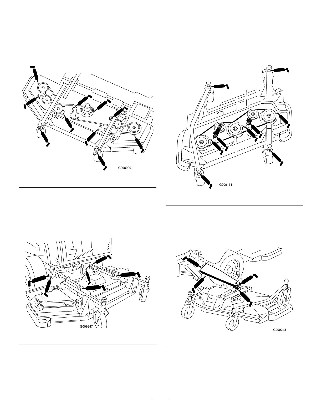
FrontMowerDeck
SideMowerDecks(EachSide)
•2caster-fork-shaftbushings(Figure52)
•5spindle-shaftbearings(locatedonthespindlehousing)
asshowninFigure52
•3idler-arm-pivotbushings(locatedontheidler-pivot
shaft)asshowninFigure52
Figure52
•4caster-fork-shaftbushings(Figure54)
•3spindle-shaftbearings(locatedonthespindlehousing)
asshowninFigure54
•2idler-arm-pivotbushings(locatedontheidler-pivot
shaft)asshowninFigure54
FrontLiftAssemblies
•2lift-armbushings(Figure53)
•2lift-armballjoints(Figure53)
•2frontdeck-lift-cylinderpivots(Figure53)
Figure53
Figure54
SideLiftAssemblies(PerSide)
•3mainlift-armbushings(Figure55)
•1lift-cylinderbushing(Figure55)
Figure55
41
Page 42

EngineMaintenance
g021 157
6
g021 152
EngineSafety
Shutofftheenginebeforecheckingtheoiloraddingoilto
thecrankcase.
Air-CleanerMaintenance
Checktheair-cleanerbodyfordamagethatcouldcauseanair
leakandreplaceitifitisdamaged.Checktheentireintake
systemforleaks,damage,orloosehoseclamps.Also,inspect
therubberintake-hoseconnectionsattheaircleanerand
turbochargertoensurethattheconnectionsarecomplete.
Servicetheair-cleanerlteronlywhenthe“CheckAirFilter”
messageisdisplayedontheInfoCenter(Figure56).Changing
theairlterbeforeitisnecessaryonlyincreasesthechanceof
dirtenteringtheenginewhenyouremovethelter.
Ensurethatthecoverisseatedcorrectlyandsealswiththe
air-cleanerbody .
cleaningprocesspreventsdebrisfrommigratinginto
theintakewhenyouremovetheprimarylter.
2.Removetheprimarylter(Figure57).
Note:Donotcleanausedelementduetothe
possibilityofdamagetotheltermedia.
Figure57
Figure56
ServicingtheAir-CleanerCover
ServiceInterval:Every50hours—Removeaircleanercover
andcleanoutdebrisDonotremovelter.
1.Pullthelatchoutwardandrotatetheair-cleanercover
counterclockwise(Figure57).
2.Removethecoverfromtheair-cleanerbody.
3.Cleananydebrisfromthecoverandinstallthecover.
Donotremovetheairlters
ServicingtheAir-CleanerFilter
1.Beforeremovingthelter,uselowpressureair275kPa
(40psi,cleananddry)toremovelargeaccumulations
ofdebrispackedbetweenoutsideofprimarylterand
thecanister.
1.Air-cleanerrestriction
sendingunit
2.Air-cleanerlatch5.Rubberoutletvalve
3.Air-cleanerbody6.Rubberintakehose
Important:
attempttocleanthesafetylter(Figure58).
Replacethesafetylterwithanewoneafterevery
3primarylterservices.
1.Safetylter
3.Inspectthenewlterforshippingdamage,checking
thesealingendofthelterandthebody.
Important:Donotuseadamagedelement.
4.Replacetheprimarylter(Figure57).
5.Insertthenewlterbyapplyingpressuretotheouter
rimoftheelementtoseatitinthecanister.
Do not
4.Air-cleanerprimarylter
removethesafetylter.Never
Figure58
Note:Avoidusinghigh-pressureair,whichcould
forcedirtthroughthelterintotheintaketract.This
Important:Donotapplypressuretotheexible
centerofthelter.
42
Page 43

6.Cleanthedirt-ejectionportlocatedintheremovable
cover.
7.Removetherubberoutletvalvefromthecover,clean
thecavity,andreplacetheoutletvalve.
8.Installthecoverorientingtherubberoutletvalveina
downwardposition-betweenapproximately5:00to
7:00whenviewedfromtheend(Figure57).
9.Securethelatch.
ServicingtheEngineOil
CheckingtheEngine-OilLevel
ServiceInterval:Beforeeachuseordaily—Checkthe
engine-oillevel.
Theengineisshippedwithoilinthecrankcase;however,
checktheoillevelbeforeandafteryoustarttheenginethe
rsttime.
Thecrankcasecapacityis8.04L(8.5USqt)withthelter.
Usehigh-qualityengineoilthatmeetsthefollowing
specications:
•APIClassicationLevelRequired:CH-4,CI-4orhigher.
•Preferredoil:SAE15W -40(above0°F)
•Alternateoil:SAE10W -30(below23°F)
ToroPremiumEngineOilisavailablefromyourdistributor
ineither15W-40or10W-30viscosity.Seethepartscatalog
forpartnumbers.Also,refertotheengineowner’ smanual
(includedwiththemachine)forfurtherrecommendations.
Note:Thebesttimetochecktheengineoiliswhenthe
engineiscoolbeforeithasbeenstartedfortheday.Ifyou
havealreadyruntheengine,allowtheoiltodrainbackdown
tothesumpforatleast10minutesbeforechecking.Iftheoil
levelisatorbelowtheAddmarkonthedipstick,addoilto
bringtheoilleveltotheFullmark.Donotoverll.Ifthe
oillevelisbetweentheFullandAddmarks,youdonotneed
toaddoil.
1.Parkthemachineonalevelsurface.
Figure59
1.Oillter
3.IftheoilisbelowtheLowmark,removetheoil-ll
capandaddoiluntilthelevelreachestheFullmark
(Figure60).
Important:Donotoverll.
1.Oil-llcap
4.Installtheoil-llcapanddipstick.
2.Dipstick
Figure60
2.Removethedipstick,wipeitclean,installitintothe
tube,andpullitoutagain(Figure59).
Note:TheoillevelshouldbeuptotheFullmark.
43
Page 44

ChangingtheEngineOil
ServiceInterval:Every250hours—Changetheengineoil
andlter.
1.Removethedrainplugandlettheoilowintoadrain
pan(Figure61).
Figure61
FuelSystem
Maintenance
ServicingtheFuelSystem
DrainingtheFuelTank
ServiceInterval:Every1,000hours—Drainandcleanthe
fueltank.
Drainandcleanthetankiffuelsystembecomescontaminated
orifyouarestoringthemachineforanextendedperiodof
time.Usecleanfueltoushoutthetank.
InspectingtheFuelLinesand
Connections
1.Engine-oildrainplug
2.Whentheoilstopsdraining,installthedrainplug.
3.Removetheoillter(Figure59).
4.Applyalightcoatofcleanoiltothenewlterseal
beforescrewingiton.
Important:Donotovertighten.
5.Addoiltothecrankcase;refertoCheckingthe
Engine-OilLevel(page43).
AdjustingtheValveClearance
ServiceInterval:Aftertherst250hours—Adjustthevalve
clearance.
Every2,000hours—Adjustthevalveclearance.
Refertotheengineowner’smanual(includedwiththe
machine)fortheadjustmentprocedure.
ServiceInterval:Every500hours—Inspectthefuellines
andconnections.
Checkthefuellinesandconnectionsevery500hoursor
yearly,whichevercomesrst.Inspectthemfordeterioration,
damage,orlooseconnections.
44
Page 45

ServicingtheWaterSeparator
ServiceInterval:Beforeeachuseordaily—Drainthewater
separator.
Every500hours—Replacethefuel/waterseparator
element.
DrainingtheWaterSeparator
1.Placeacleancontainerunderthewaterseparator
(Figure62).
2.Openthedrainplugandoperatethepumptodrain
contaminates(Figure62).
8.Applyacoatingofcleanfuelorengineoiltothenew
O-ringandelementseal.
9.Spinthebowlontothenewelement,thenspinthem
bothontothelterheadbyhandonly.
Note:Donotusetools.
10.Closethedrainplug.
11.Connectthewatersensor(electricalconnector)from
thebottomofthewaterseparator.
12.Withtheventplugstillloosened,operatetheprimer
pumpuntilthefuelpurgesattheventplug.
13.Closetheventplug,starttheengine,andcheckfor
leaks.
Note:Correctasnecessarywiththeengineoff.
ReplacingtheFuelFilter
ServiceInterval:Every500hours—Replacethefuel-lter
element
1.Cleantheareaaroundthefuel-lterhead(Figure63).
Figure62
1.Water-separator-lter
canister
2.Primingpump5.Ventplug
3.Drainplug
3.Closethedrainplug.
4.Flow-checkvalve
ReplacingtheFuel-FilterElement
1.Placeacleancontainerunderthewaterseparator.
2.Drainsomefuelbylooseningtheventplugand
openingthedrainplug(Figure62).
3.Disconnectthewatersensor(electricalconnector)
fromthebottomofthewaterseparator.
4.Cleantheareawherethelterelementmountstothe
head.
5.Removethelterelementandbowl.
6.Removetheelementfromthebowlandcleanthe
mountingsurface.
Figure63
1.Fuel-lterhead
2.Removethelterandcleanthelter-head-mounting
surface(Figure63).
3.Lubricatetheltergasketwithclean,lubricatingengine
oil;refertotheengineowner’smanual(includedwith
themachine)foradditionalinformation.
4.Installthedryltercanister,byhand,untilthegasket
contactsthelterhead,thenrotateitanadditional
1/2turn.
5.Loosenthebanjottingonthefuel-lterhousing
(Figure64).
2.Filter
7.CleantheO-ringglandonthebowl.
45
Page 46

ElectricalSystem
g021 155
Maintenance
ElectricalSystemSafety
•Disconnectthebatterybeforerepairingthemachine.
Disconnectthenegativeterminalrstandthepositive
last.Connectthepositiveterminalrstandthenegative
last.
•Batteryacidispoisonousandcancauseburns.Avoid
contactwithyourskin,eyes,andclothing.Protectyour
face,eyes,andclothingwhenworkingwithabattery.
Figure64
1.Fuellter3.WaterSeparator
2.Banjotting
6.Operatethewater-separatorprimingpumpuntilasolid
streamoffuelisdetectedatthebanjotting(Figure
64).
7.Tightenthefuel-lterbanjotting.
8.Pushdowntheprimingpumpandturnitclockwise
tosecure.
9.Starttheengineandcheckforfuelleaksaroundthe
lterhead.
4.Primingpump
•Batterygasescanexplode.Keepcigarettes,sparks,and
amesawayfromthebattery.
•Chargethebatteriesinanopen,well-ventilatedarea,
awayfromsparksandames.Unplugthechargerbefore
connectingordisconnectingthebattery.Wearprotective
clothinganduseinsulatedtools.
•Donotuseapressurewashernearanyelectronic
components.
WARNING
CALIFORNIA
Proposition65Warning
Batteryposts,terminals,andrelated
accessoriescontainleadandleadcompounds,
chemicalsknowntotheStateofCalifornia
tocausecancerandreproductiveharm.
Washhandsafterhandling.
LocatingtheFuses
Thetraction-unitfuses(Figure67)arelocatedinthe
power-centerconsole(Figure66).
Figure65
46
Page 47

Figure66
G021 159G021 159
1
2
3
1.Power-centerconsole2.Knob
Thecabfuses(Figure68)arelocatedinthefuseboxonthe
cabheadliner(Figure69).
Figure68
1.Fuse—60A
2.Fuseblock
Figure67
3.Alternatepositivepostfor
chargingorjumpstarting
Figure69
1.Cabfusebox
2.Fuses
CheckingtheBattery Condition
ServiceInterval:Every50hours—Checktheconditionof
thebattery.
Important:Beforeweldingonthemachine,disconnect
thenegativecablefromthebatterytopreventdamage
totheelectricalsystem.Also,youmustdisconnectthe
engine,InfoCenter,andmachinecontrollersbefore
weldingonthemachine.
Note:Checkthebatteryconditionweeklyorafterevery50
hoursofoperation.Keeptheterminalsandtheentirebattery
caseclean,becauseadirtybatterydischargesslowly .Toclean
thebattery,washtheentirecasewithasolutionofbakingsoda
andwater.Rinsewithclearwater.Coatthebatterypostsand
cableconnectorswithGrafo112X(skin-over)grease(Toro
PartNo.505-47)orpetroleumjellytopreventcorrosion.
47
Page 48

ChargingtheBattery
1
2
3
4
G003792
WARNING
Chargingthebatteryproducesgassesthatcan
explode.
Donotsmokenearthebattery,andkeepsparksand
amesawayfromthebattery.
Important:Keepthebatteryfullycharged.Thisis
especiallyimportanttopreventbatterydamagewhen
thetemperatureisbelow32°F(0°C).
1.Performthepre-maintenanceprocedure;referto
PreparingtheMachineforMaintenance(page38).
2.Cleantheexteriorofthebatterycaseandthebattery
posts.
Note:Connecttheleadsofthebatterychargerto
batterypostsbeforeconnectingthechargertothe
electricalsource.
3.Lookatthebatteryandidentifythepositiveand
negativebatteryposts.
Battery-chargerTable
ChargersettingChargingtime
4to6amperes30minutes
25to30amperes10to15minutes
7.Whenthebatteryisfullycharged,unplugthecharger
fromtheelectricalsource,thendisconnectthecharger
leadsfromthebatteryposts(Figure70).
UsingtheAlternatePositive Post
Ifyouneedtojumpstartthemachineorchargethebatteries,
youcanusethealternatepositivepostinsteadofthepositive
batterypost(Figure67).Thealternatepositivepostislocated
inthefrontofthepowercenterconsole(Figure66).
CalibratingtheTractionPedal
ServiceInterval:Every1,000hours—Calibratethetraction
pedal.
4.Connectthepositiveleadofthebatterychargertothe
positivebatterypost(Figure70).
Figure70
1.Positivebatterypost
2.Negativebatterypost
5.Connectthenegativeleadofthebatterychargertothe
negative-batterypost(Figure70).
6.Connectthebatterychargertotheelectricalsource,and
chargethebatteryaccordingtotheBattery-charging
Tablethatfollows.
3.Red(+)chargerlead
4.Black(-)chargerlead
ContactyourlocalTorodistributororrefertotheToroService
Manualforassistance.
Important:Donotoverchargethebattery.
48
Page 49
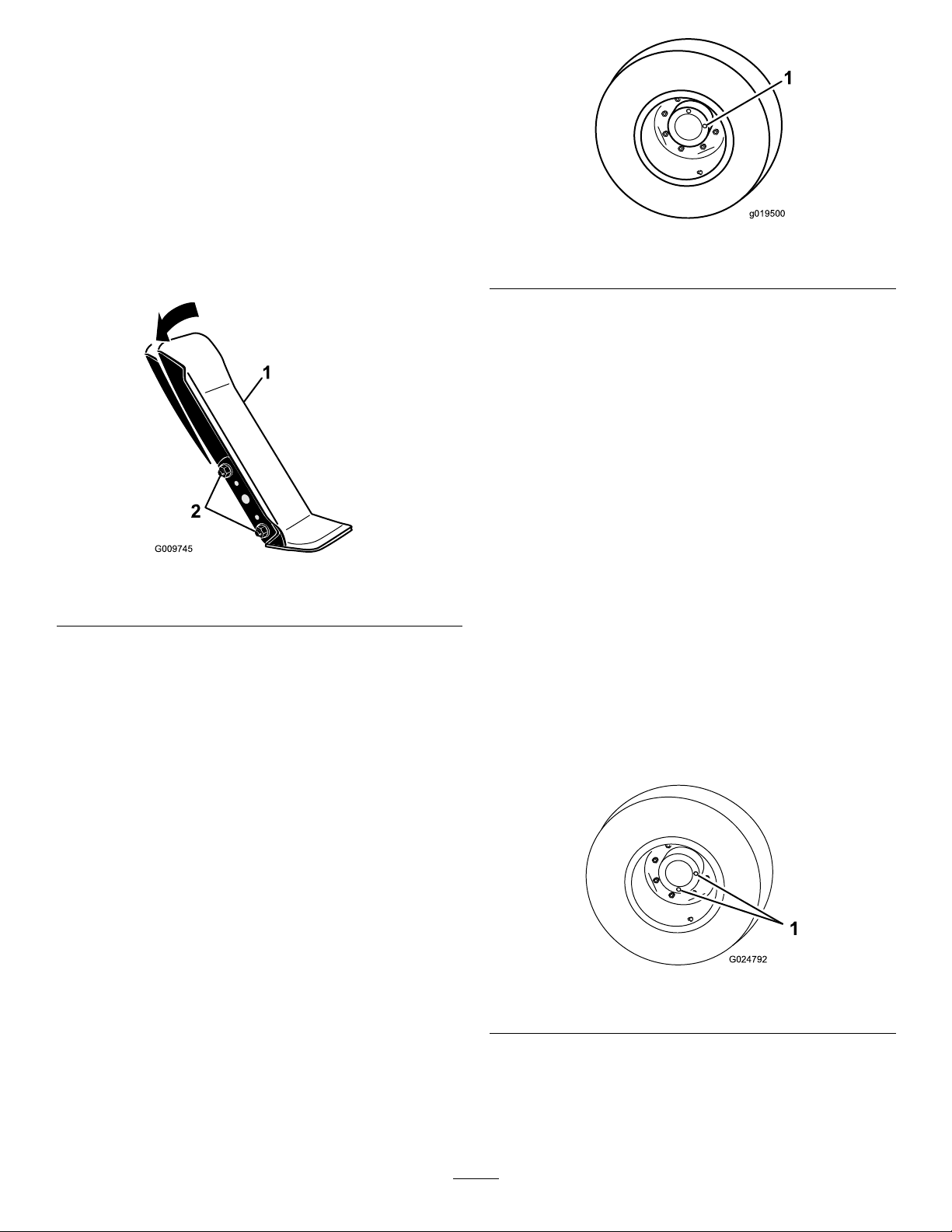
DriveSystem
g019500
G024792
1
Maintenance
AdjustingtheTraction-Pedal Angle
Youcanadjusttheoperatingangleofthetractionpedalfor
yourcomfort.
Figure72
1.Loosenthe2nutsandboltssecuringtheleftsideofthe
tractionpedaltothebracket(Figure71).
Figure71
1.Tractionpedal2.Mountingnutsandbolts
2.Pivotthepedaltothedesiredoperatingangleand
tightenthenuts(Figure71).
1.Check/drainplug(3o'clockposition)
2.Removetheplugatthe3o’clockposition(Figure72).
Note:Theoillevelshouldbewithin6mm(1/4inch)
ofthecheck-plughole.
3.Iftheoillevelislow,removetheplugatthe12o’clock
positionandaddoiluntilitbeginstoowoutofthe
holeatthe3o’clockposition.
4.Installbothplugs.
5.Repeatsteps1through3ontheoppositeplanetary-gear
assembly.
ChangingthePlanetary-Drive Gear/BrakeOil
ServiceInterval:Aftertherst250hours—Changethe
planetary-drivegear/brakeoil.
Every800hours
UseahighqualitySAE85W -140gearlubeasreplacement.
CheckingthePlanetary-Drive Gear/Brake-OilLevel
ServiceInterval:Every400hours—Checkthe
planetary-drivegear/brake-oillevel
(checkifyouobserveexternalleakage).
UsehighqualitySAE85W-140gearlubeasareplacement.
1.Withthemachineonalevelsurface,positionthewheel
sothat1checkplugisatthe12o'clockpositionand
theotherisatthe3o'clockposition(Figure72).
1.Withmachineonlevelsurface,positionawheelsoone
ofthecheck/drainplugsisatthelowest(6o’clock)
position(Figure73).
Figure73
1.Check/drainplugs
2.Placeadrainpanundertheplanetaryhub,removeboth
plugs,andallowoiltodrain.
3.Placeadrainpanunderthebrakehousing,removethe
drainplug,andallowtheoiltodrain(Figure74).
49
Page 50

g021 156
Figure74
G024858
1
1.Drainplug2.Brakehousing
4.Whenalloftheoilhasdrainedfrombothlocations,
installthepluginthebrakehousing.
5.Rotatethewheeluntiltheopenholesintheplanetary
areatthe11o’clockand1o'clockpositions.
CheckingtheRear-Wheel Toe-in
ServiceInterval:Every1,000hours—Checktherear-wheel
toe-in.
1.Measurethecenter-to-centerdistance(ataxleheight)at
thefrontandrearofthesteeringtires(Figure76).
Note:Thefrontmeasurementcannotbemorethan3
mm(0.12inch)lessthantherearmeasurement.
Figure75
1.Holesatthe1 1o’clockand1o'clockpositions
6.Througheitheropenhole,slowlylltheplanetarywith
0.53to0.59L(18to20ounces)ofhighqualitySAE
85W-140wt.gearlube.
7.Installtheplugs.
8.Repeattheprocedureontheoppositeplanetary/brake
assembly
Figure76
1.Center-to-centerdistance
2.Tie-rodclamps
2.Toadjust,loosentheclampsatbothendsofthetie
rods(Figure76).
3.Rotatethetie-rodendtomovethefrontofthetire
inwardoroutward.
4.Tightenthetie-rodclampswhentheadjustmentis
correct.
50
Page 51

CoolingSystem
Maintenance
CoolingSystemSafety
DANGER
Therotatingfansanddrivebeltscancausepersonal
injury.
•Donotoperatethemachinewithoutthecovers
inplace.
CAUTION
Dischargeofhot,pressurizedcoolantortouchinga
hotradiatorandsurroundingpartscancausesevere
burns.
•Donotremovetheradiatorcapwhentheengine
ishot.Alwaysallowtheenginetocoolatleast15
minutesoruntiltheradiatorcapiscoolenough
totouchwithoutburningyourhandbefore
removingtheradiatorcap.
•Donottouchtheradiatorandsurroundingparts
thatarehot.
DANGER
Swallowingenginecoolantcancausepoisoning.
•Donotswallowenginecoolant.
•Keepoutofreachfromchildrenandpets.
CheckingtheCoolingSystem
•Keepngers,hands,andclothingclearofthe
rotatingfananddrivebelt.
•Shutofftheengineandremovetheignitionkey
beforeperformingmaintenance.
CAUTION
Iftheenginehasbeenrunning,thepressurized,hot
coolantcanescapeandcauseburns.
•Donotopentheradiatorcapwhentheengine
isrunning.
•Usearagwhenopeningtheradiatorcap,and
openthecapslowlytoallowsteamtoescape.
1.Carefullyremovetheradiatorcapandexpansiontank
cap(Figure77).
ServiceInterval:Beforeeachuseordaily—Checkthe
coolantlevel.
Checklevelofcoolantatthebeginningofeachday.The
capacityofthesystemonamachinewithoutacabis10.4L
(13.5qt)andwithacabis17L(18qt).
RecommendedCoolant
Note:CoolantmustmeetorexceedASTMStandard3306
Glycolbasedpre-dilutedcoolant(50/50blend)
or
Glycolbasedcoolantmixedwithdistilledwater(50/50blend)
or
Glycolbasedcoolantmixedwithgoodqualitywater(50/50
blend)aslistedintheCumminsManual
CaCO
+MgCO
3
Chloride<40ppm(CI)
Sulfer<100ppm(SO
3
<170ppm
)
4
Figure77
1.Expansiontank2.Radiatorcap
2.Checkthecoolantlevelintheradiator.
Note:Theradiatorshouldbelledtothetopofthe
llerneckandtheexpansiontanklledtotheFull
mark.
3.Ifthecoolantislow,addrecommendedreplacement
coolant,asrequired.
Note:Donotusewateronlyor
alcohol/methanol-basedcoolants.
4.Installtheradiatorcapandexpansion-tankcap.
51
Page 52

ServicingtheEngine-Cooling
BrakeMaintenance
System
ServiceInterval:Every100hours—Inspectthe
cooling-systemhoses.
Every2years—Flushthecoolingsystemandreplace
uid.
Beforeeachuseordaily(moreoftenindustyordirty
conditions).
1.Shutofftheengineandraisethehood.
2.Cleantheengineareathoroughlyofalldebris.
3.Rotatethelatchessecuringtheoilcoolertotheframe
(Figure78).
AdjustingtheServiceBrakes
Adjusttheservicebrakeswhenthereismorethan50mm(2
inches)of“freetravel”ofthebrakepedalorwhenthebrakes
donotworkeffectively.Freetravelisthedistancethebrake
pedalmovesbeforeyoufeelbrakingresistance.
1.Disengagethelockinglatchfromthebrakepedalsso
thatbothpedalsworkindependentlyofeachother.
2.Toreducethefreetravelofthebrakepedals,adjust
thebrakecablesasfollows:
A.Loosenthefrontnutonthethreadedendofthe
brakecable.
Note:Foreasieraccesstotheadjustingnuts,you
mayunhookandremovethespring.
Figure78
1.Latches
4.Pivottheoilcoolerrearward.
5.Cleanbothsidesoftheoilcoolerandradiatorarea
thoroughlywithcompressedair.
Note:Startfromthefansideandblowthedebrisout
towardstheback.Thencleanfromthebacksideand
blowtowardsthefront.Repeatprocedureseveraltimes
untilallchaffanddebrisisremoved.
Important:Cleaningtheradiatororoilcooler
withwatercanpromoteprematurecorrosionand
damagetocomponents.
6.Pivottheoilcoolerbackintoposition.
7.Securetheoilcoolertotheframewiththelatchesand
closethehood.
Figure79
1.Brakecable3.Rearnut
2.Frontnut
B.Tightentherearnutuntilthebrakepedalshave
50mm(2inches)offreetravel.
C.Repeattheprocedureontheotherbrakecable.
D.Tightenthefrontnutsafteradjustingthebrakes.
E.Installthesprings,ifremoved.
Important:Adjustingthebraketensiontootight
decreasesthelifeofthefriction-padmaterial.
4.Spring
52
Page 53

BeltMaintenance
ReplacingtheBlade-Drive Belts
ServicingtheAlternatorBelt
ServiceInterval:Aftertherst10hours—Checkthe
alternator-belttension.
Every1,000hours—Checkthealternator-belttension.
Refertotheengineowner'smanual(includedwiththe
machine)fortheservicingprocedure.
ServicingtheCompressorBelt
Model31599Only
ServiceInterval:Aftertherst10hours—Checkthe
compressor-belttension.
Every1,000hours—Checkthecompressor-belt
tension.
1.Loosenthecompressor-pivotboltandadjustingbolt
(Figure80).
2.Insertatorquewrenchintothesquareholeinthe
compressorbracket(Figure80).
ServiceInterval:Every50hours—Inspecttheblade-drive
belts.
Every1,000hours—Replacetheblade-drivebelts.
Theblade-drivebelt,tensionedbythespring-loadedidler
pulley,isverydurable.However,aftermanyhoursofuse,the
beltwillshowsignsofwear.Signsofawornbeltaresquealing
whenthebeltisrotating;bladesslippingwhencuttinggrass;
frayededges;burnmarks;andcracks.Replacethebeltifany
ofthesesignsoccur.
ReplacingtheFrontMower-DeckBelt
1.Lowerthemowerdecktotheshopoor.
2.Removethebeltcoversfromthetopofthemower
deckandsetthecoversaside.
3.Onthefrontdeck,loosenthejamnutsontheidler
pulleystopscrewandthreadthestopscrewintothe
bracket(Figure81).
Figure80
1.Compressorbelt3.Squarehole
2.Mountingbolt4.Pivotbolt
3.Rotatethewrenchuntilyouattainatorqueof37to45
N·m(27to33ft-lb).
4.Tightenthemountingbolts.
Figure81
1.Idlerstopscrew
2.Idlerpulley
4.Usingaratchetwrenchorsimilartool,movetheidler
pulleyawayfromthedrivebelttoreleasethebelt
tensionandallowthebelttobeslippedoffthedeck
pulleys(Figure81).
5.Removetheboltssecuringthehydraulicmotortothe
mowerdeck(Figure82).
53
3.2.5mmto4mm(0.10to
0.16inch)
Page 54

Figure82
114-0922
1.Hydraulicmotor2.Mountingbolts
6.Liftthemotoroffthemowerdeckandlayitontop
ofthemowerdeck.
7.Removetheoldbeltfromaroundthespindlepulleys
andidlerpulley.
8.Routethenewbeltaroundthespindlepulleysand
idler-pulleyassembly(Figure83).
Figure83
9.Adjustthestopscrewontheidlerpulleyandtighten
thejamnuts.
ReplacingtheSideMower-DeckBelts
Figure84
1.Idlerpulleys
6.Removetheoldbeltfromaroundthespindlepulleys
andidlerpulley.
7.Routethenewbeltaroundthespindlepulleysand
idler-pulleyassembly(Figure85andFigure86).
Figure85
Rightdeck
Note:Toremovethelowerbelt,youmustremovetheupper
beltrst.
1.Lowerthemowerdecktotheoor.
2.Removethebeltcoversfromthetopofthemower
deckandsetthecoversaside.
3.Removetheboltssecuringthehydraulicmotortothe
mowerdeck(Figure82).
4.Liftthemotoroffthemowerdeckandlayitontop
ofthemowerdeck.
5.Usingaratchetwrenchorsimilartool,movetheidler
pulleysawayfromthedrivebelttoreleasethebelt
tensionandallowthebelttoslipoffthepulleys(Figure
84).
Figure86
Leftdeck
54
Page 55

HydraulicSystem
Maintenance
HighViscosityIndex/LowPourPoint
Anti-wearHydraulicFluid,ISOVG46(cont'd.)
HydraulicSystemSafety
WARNING
Hydraulicuidescapingunderpressurecan
penetrateskinandcauseinjury.
•Ensurethatallhydraulic-uidhosesand
linesareingoodconditionandallhydraulic
connectionsandttingsaretightbefore
applyingpressuretothehydraulicsystem.
•Keepyourbodyandhandsawayfrompinhole
leaksornozzlesthatejecthigh-pressure
hydraulicuid.
•Usecardboardorpapertondhydraulicleaks.
•Safelyrelieveallpressureinthehydraulicsystem
beforeperforminganyworkonthehydraulic
system.
•Seekimmediatemedicalattentionifuidis
injectedintoskin.
CheckingtheHydraulicFluid
ServiceInterval:Beforeeachuseordaily—Checkthe
hydraulicuidlevel.
Themachinesreservoirislledatthefactorywith
approximately71.9L(19U.S.gallons)ofhighquality
hydraulicuid.Checkthelevelofthehydraulicuid
beforetheengineisrststartedanddailythereafter.
UseToroPremiumAllSeasonHydraulicFluid(Available
in5gallonpailsor55gallondrums.SeethePartsCatalogor
Torodistributorforpartnumbers.)
IftheTorouidisnotavailable,otheruidsmaybeused
providedtheymeetallthefollowingmaterialproperties
andindustryspecications.Consultwithyourlubricant
distributortoidentifyasatisfactoryproduct.
ViscosityIndexASTM
D2270
PourPoint,ASTMD97-34°Fto-49°F
FZG,Failstage
Watercontent(newuid)500ppm(maximum)
IndustrySpecications:VickersI-286-S(QualityLevel),
VickersM-2950-S(Quality
Level),DenisonHF-0
Important:TheISOVG46Multigradeuidhasbeen
foundtoofferoptimalperformanceinawiderangeof
temperatureconditions.Foroperationinconsistently
highambienttemperatures,18°C(65°F)to49°C
(120°F),ISOVG68hydraulicuidmayofferimproved
performance.
PremiumBiodegradableHydraulicFluid-MobilEAL
EnviroSyn46H
Important:MobilEALEnviroSyn46Histheonly
syntheticbiodegradableuidapprovedbyT oro.This
uidiscompatiblewiththeelastomersusedinToro
hydraulicsystemsandissuitableforawide-range
oftemperatureconditions.Thisuidiscompatible
withconventionalmineraloils,butformaximum
biodegradabilityandperformance,thehydraulicsystem
shouldbethoroughlyushedofconventionaluid.The
oilisavailablein5galloncontainersor55gallondrums
fromyourMobilDistributor.
Important:Manyhydraulicuidsarealmostcolorless,
makingitdifculttospotleaks.Areddyeadditivefor
thehydraulic-systemoilisavailablein20ml(2/3oz)
bottles.1bottleissufcientfor15to22L(4to6gallons)
ofhydraulicoil.OrderToroPartNo.44-2500fromyour
authorizedT orodistributor.
1.Performthepremaintenanceprocedure;referto
PreparingtheMachineforMaintenance(page38).
2.Ontherightsideofthemachine,raisetheaccesscover
toexposethehydraulic-tankcap(Figure87).
140to160
11orbetter
Note:T orodoesnotassumeresponsibilityfordamage
causedbyimpropersubstitutions,souseonlyproducts
fromreputablemanufacturerswhowillstandbehindtheir
recommendation.
HighViscosityIndex/LowPourPoint
Anti-wearHydraulicFluid,ISOVG46
MaterialProperties:
St@40°C44to48 Viscosity,ASTMD445
St@100°C7.9to8.5
55
Page 56

Figure87
1.Hydraulictankcap
3.Cleantheareaaroundthellerneckandcapofthe
hydraulictank(Figure87).
ChangingtheHydraulicFluid andFilters
ServiceInterval:Every1,000hours—Changethehydraulic
uidandlters.
Iftheuidbecomescontaminated,contactyourlocalToro
distributorbecausethesystemmustbeushed.Contaminated
uidlooksmilkyorblackwhencomparedtocleanoil.
UseT ororeplacementlters(PartNo.86–6110fortheleft
sideofthemachineand75-1310fortherightsideofthe
machine).
Important:Useofanyotherltermayvoidthewarranty
onsomecomponents.
1.Positionthemachineonalevelsurface,lowerthe
mowerdecks,shutofftheengine,engagetheparking
brakes,andremovetheignitionkey.
2.Placealargedrainpanunderthehydraulicuidtank.
3.Removethedrainplug(Figure89)fromthebottomof
thetankandletthehydraulicuidowintothepan.
Installthedrainplugwhenthehydraulicuidstops
draining.
4.Removethecapfromthellerneck.
5.Removethedipstickfromthellerneckandwipeit
withacleanrag.Insertthedipstickintothellerneck,
thenremoveitandchecktheuidlevel(Figure88).
Note:Theuidlevelshouldbewithinthe
safe-operatingrangeonthedipstick
Figure88
1.Safe-operatingrange
6.Ifthelevelislow ,addtheappropriateuidtoraisethe
leveltotheuppermark.
7.Installthedipstickandcapontothellerneck.
8.Closethecover.
Figure89
1.Hydrauliclter
2.Hydrauliclter
4.Cleantheareaaroundtheltermountingareas.
5.Placeadrainpanunderthelterandremovethelter
(Figure89).
6.Lubricatethenewltergasketandllthelterwith
hydraulicuid.
7.Ensurethatthelter-mountingareaisclean.Screw
theltersonuntilthegasketscontactsthemounting
plates,thentightenthelteranadditional1/2turn.
8.Fillthereservoirwithhydraulicuid;refertoChecking
theHydraulicFluid(page55).
3.Hydraulictankdrainplug
Important:Useonlythehydraulicuids
specied.Otheruidscouldcausesystem
damage.
9.Installthereservoircap.
56
Page 57

10.Starttheengineanduseallofthehydrauliccontrolsto
distributehydraulicuidthroughoutthesystem.Check
forleaks,thenshutofftheengine.
MowerMaintenance
11.Checktheuidlevelandaddenoughtoraiselevelthe
leveltotheFullmarkonthedipstick.
Important:Donotoverll.
CheckingtheHydraulicLines andHoses
ServiceInterval:Every2years—Replacemovinghoses.
Inspectthehydrauliclinesandhosesdailyforleaks,kinked
lines,loosemountingsupports,wear,loosettings,weather
deterioration,andchemicaldeterioration.Makeallnecessary
repairsbeforeoperatingthemachine.
Inspectingthe Hydraulic-SystemTestPorts
Thetestportsareusedtotestthepressureinthehydraulic
circuits.ContactyourlocalTorodistributororrefertothe
ToroServiceManualforassistance.
Pivoting(Tilting)theFront MowerDeckUpright
Note:Althoughnotneededfornormalmaintenance
procedures,youcanpivot(tilt)thefrontmowerdeckupright.
1.Raisethefrontmowerdeckslightlyofftheoor.
2.Performthepremaintenanceprocedure;referto
PreparingtheMachineforMaintenance(page38).
3.Removetheretainerclipanddisconnectthedamper
assemblyfromthemowerdeck(Figure90).
Figure90
1.Damperassembly2.Retainerclip
4.Removethehairpincotterandclevispinsecuringthe
height-of-cutchainstotherearofthemowerdeck
(Figure91).
57
Page 58

Figure91
AdjustingtheMower-Deck Pitch
MeasuringtheMower-DeckPitch
Themower-deckpitchisthedifferencebetweenthe
height-of-cutfromthefrontofthebladeplanetothatofthe
backofthebladeplane.Setabladepitchof7.5mm(0.3
inch);i.e.,thebackofthebladeplaneshouldbe7.5mm(0.3
inch)higherthanthefrontofthebladeplane.
1.Positionthemachineonalevelsurfaceontheoor.
2.Setthemowerdecktothedesiredheightofcut.
3.Ensurethatthewingletsareleveltothefrontdeckand
thefrontdeckislevelsidetoside.
AdjustingtheFront-Mower-DeckPitch
1.Rotatethe2outer,frontbladesandthewingletblades,
sothattheypointstraightforward(Figure93).
1.Height-of-cutchain
2.Clevispin
5.Starttheengine,slowlyraisethefrontmowerdeck,
shutofftheengine,andremovetheignitionkey.
6.Wedgeablockofwoodbetweentherearofthedeck
andthemachine(Figure92).
1.Blockofwood
3.Hairpincotter
Figure92
Pivoting(Tilting)theFront
Figure93
1.Use1ofthesebladesfor
measuringthefront-blade
height.
2.Usingashortruler,measurefromtheoortothefront
tipofthefrontbladeandrecordthisdimension.
3.Measurefromtheoortothebacktipofthewinglet
bladeandrecordthisdimension.
4.Subtractthefrontdimensionfromthereardimension
tocalculatethebladepitch.
5.Loosenthejamnutsonthetoporbottomofthe
height-of-cutchainU-bolt(Figure94).
2.Use1ofthesebladesfor
measuringtherear-blade
height.
MowerDeckDown
1.Withthehelpofanotherpersonholdingthefrontof
themowerdeck,removetheblockofwood.
2.Sitontheseat,starttheengine,andlowerthemower
deckuntilitisslightlyofftheoor.
3.Securetheheight-of-cutchainstotherearofthe
mowerdeck.
4.Connectthedamperassemblyandsecureitwiththe
retainerclip.
Note:Loosenortightentheheight-of-cutchainnuts
equallysothatthedeckremainslevelfromsidetoside.
58
Page 59

Figure94
1.Height-of-cutchain3.Nut(2)
2.U-bolt
6.Adjusttheothersetofnutstoraiseorlowertherear
ofthemowerdeckandattainthecorrectmower-deck
pitch.
7.Tightenthejamnuts.
2.Positiontheshims,asrequired,toraiseorlowerthe
castorwheeluntilthemowerdeckhasthecorrectpitch.
3.Installthetensioningcap.
ServicingtheCastor-Arm Bushings
Thecasterarmshavebushingspressedintothetopand
bottomofthetube,andaftermanyhoursofoperation,the
bushingswear.Tocheckthebushings,movethecasterfork
backandforthandfromsidetoside.Ifthecasterspindleis
looseinsidethebushings,thebushingsarewornandmustbe
replaced.
1.Raisethemowerdecksothatthewheelsareoff
theoor.Blockthemowerdecksothatitcannot
accidentallyfall.
2.Removethetensioningcap,spacer(s),andthrust
washerfromthetopofthecastorspindle.
Note:Recordthepositionofthewashersandspacers
beforeremovalsothedeckpitchdoesnothavetobe
adjusted.
3.Pullthecastorspindleoutofthemountingtube.
Allowthethrustwasherandspacer(s)toremainon
thebottomofthespindle.
4.Insertapinpunchintothetoporbottomofthe
mountingtubeanddrivethebushingoutofthetube
(Figure96).
AdjustingtheSide-Mower-DeckPitch
1.Removethetensioningcapfromthecaster-spindle
shaftandslidethespindleoutofthecasterarm(Figure
95).
Figure95
1.Tensioningcap4.Topaxle-mountinghole
2.Spacers5.Casterwheel
3.Shims
Figure96
1.Castorarmtube
2.Bushings
5.Drivetheotherbushingoutofthetube.
6.Cleantheinsideofthetubestoremovedirt.
7.Applygreasetotheinsideandoutsideofthenew
bushings.
8.Usingahammerandatplate,drivethebushingsinto
themountingtube.
9.Inspectthecastorspindleforwearandreplaceitifit
isdamaged.
10.Pushthecastorspindlethroughthebushingsand
mountingtube.Slidethethrustwasherandspacer(s)
ontothespindle.
11.Installthetensioningcaponthecastorspindletoretain
allpartsinplace.
59
Page 60

ServicingtheCasterWheels andBearings
ServiceInterval:Every500hours—Inspectthemower-deck
caster-wheelassemblies.
1.Removethelocknutfromtheboltholdingthe
caster-wheelassemblybetweenthecasterforkorthe
caster-pivotarm(Figure97).
Figure97
BladeMaintenance
BladeSafety
DANGER
Awornordamagedbladecanbreak,andapiece
ofthebladecouldbethrownatyouorbystanders,
resultinginseriouspersonalinjuryordeath.
Tryingtorepairadamagedblademayresultin
discontinuedsafetycerticationoftheproduct.
•Inspectthebladeperiodicallyforwearor
damage.
•Nevertrytostraightenabladethatisbentor
weldabrokenorcrackedblade.
•Replaceawornordamagedblade.
•Usecarewhencheckingtheblades.Wrapthebladesor
weargloves,andusecautionwhenservicingtheblades.
Onlyreplacetheblades;neverstraightenorweldthem.
•Onmulti-bladedmachines,takecareasrotating1blade
cancauseotherbladestorotate.
1.Casterwheel
2.Casterfork
2.Graspthecasterwheelandslidetheboltoutofthe
forkorpivotarm(Figure97).
3.Removethebearingfromthewheelhubandallowthe
bearingspacertofallout(Figure97).
4.Removethebearingfromtheoppositesideofthe
wheelhub(Figure97).
5.Checkthebearings,spacer,andinsideofthewheelhub
forwear.
Note:Replaceanydamagedparts.
6.Toassemblethecasterwheel,pushthebearinginto
thewheelhub.
Note:Wheninstallingthebearings,pressontheouter
raceofthebearing.
7.Slidethebearingspacerintothewheelhubandpush
theotherbearingintotheopenendofthewheelhub
tocaptivatethebearingspacerinsidethewheelhub.
8.Installthecaster-wheelassemblybetweenthecaster
forkandsecureitinplacewiththeboltandlocknut.
3.Bearing
4.Bearingspacer
CheckingforaBentBlade
Afterstrikingaforeignobject,inspectthemachinefor
damageandmakerepairsbeforerestartingandoperatingthe
equipment.Torqueallthespindle-pulleynutsto176to203
N·m(130to150ft-lb).
1.Positionthemachineonalevelsurface.
2.Raisethemowerdeck,engagetheparkingbrake,put
thetractionpedalinNEUTRAL,makesurethatthe
PTOswitchisintheOFFposition,shutofftheengine,
andremovetheignitionkey.
3.Blockthemowerdecktopreventitfromaccidentally
falling.
4.Rotatethebladeuntiltheendsfaceforwardand
backward,andmeasurefromtheinsideofthemower
decktothecuttingedgeatthefrontoftheblade
(Figure98).
Note:Recordthisdimension.
Figure98
5.Rotatetheoppositeendofthebladeforwardand
measurebetweenthemowerdeckandcuttingedgeof
thebladeatthesamepositionasinstep4.
Note:Thedifferencebetweenthedimensions
obtainedinsteps4and5mustnotexceed3mm(1/8
inch).Ifthedimensionexceeds1/8inch(3mm),the
60
Page 61

bladeisbentandmustbereplaced;refertoRemoving
andInstallingaBlade(page61).
InspectingandSharpeningthe CutterBlade(s)
RemovingandInstallinga Blade
Replacethebladeifithitsasolidobject,ifitisoutofbalance,
orifitisbent.AlwaysusegenuineTororeplacementblades
tobesureofsafetyandoptimumperformance.Neveruse
replacementbladesmadebyothermanufacturersbecause
theycouldbedangerous.
1.Raisethemowerdecktothehighestposition.
2.Performthepremaintenanceprocedure;referto
PreparingtheMachineforMaintenance(page38).
3.Blockthemowerdecktopreventitfromaccidentally
falling.
4.Grasptheendofthebladeusingaragorthickly
paddedgloveandremovethebladebolt,anti-scalpcup,
andbladefromthespindleshaft(Figure99).
ServiceInterval:Aftertherst10hours
Every50hours
Beforeeachuseordaily
Youmustconsider2areasofthebladewhencheckingand
servicingit:thesailandthecuttingedge.Bothcuttingedges
andthesail,whichistheturned-upportionoppositeofthe
cuttingedge,contributetoagoodqualityofcut.Thesail
isimportantbecauseitliftsthegrassupstraight,thereby
producinganevencut.However,thesailgraduallywears
downduringoperation,whichisnormal.Asthesailwears
down,thequalityofcutdegradessomewhat,althoughthe
cuttingedgesaresharp.Thecuttingedgeoftheblademust
besharpsothatthegrassiscut,nottorn.Adullcutting
edgeisevidentwhenthetipsofthegrassappearbrownand
shredded.Sharpenthecuttingedgestocorrectthiscondition.
1.Positionthemachineonalevelsurface,raisethe
mowerdeck,engagetheparkingbrake,putthetraction
pedalinNEUTRAL,ensurethatthePTOswitchisin
theOFFposition,shutofftheengine,andremovethe
ignitionkey .
2.Examinethecuttingendsofthebladecarefully
(especiallywheretheatandcurvedpartsoftheblade
meet)asshowninFigure100.
Figure99
1.Bladebolt2.Anti-scalpcup
5.Installtheblade,anti-scalpcup,andbladebolt.
6.Torquethebladeboltto115to149N·m(85to110
ft-lb).
Important:Thecurvedpartoftheblademust
pointtowardtheinsideofthemowerdeckto
ensurepropercutting.
Note:Afterstrikingaforeignobject,torqueallthe
spindle-pulleynutsto176to203N·m(130to150ft-lb)
andthebladeboltsto115to149N·m(85to110ft-lb).
Note:Sincesandandabrasivematerialcanwearaway
themetalthatconnectstheatandcurvedpartsofthe
blade,checkthebladebeforeusingthemower.Ifyou
noticewear,replacetheblade(Figure100).
Figure100
1.Cuttingedge3.Wear/slotforming
2.Curvedarea4.Crack
3.Examinethecuttingedgesofalloftheblades.
4.Sharpenthecuttingedgesiftheyaredullornicked
(Figure101).
61
Page 62

Miscellaneous Maintenance
ServicingtheSpark-Arrestor
Figure101
1.Sharpenattheoriginalangle.
Note:Sharpenonlythetopofthecuttingedge
andmaintaintheoriginalcuttingangletoensurethe
sharpness.
Note:Thebladewillremainbalancedifthesame
amountofmetalisremovedfrombothcuttingedges.
Note:Removethebladesandsharpenthemonagrinder.
Aftersharpeningthecuttingedges,installthebladewith
theanti-scalpcupandbladebolt;refertoRemovingand
InstallingaBlade(page61).
CorrectingaMower-Deck Mismatch
Whenthereismismatchbetweenthebladesonasingle
mowerdeck,thegrassappearsstreakedwhenitiscut.You
cancorrectthisproblembyensuringthatthebladesare
straight.
Mufer
ServiceInterval:Every250hours—Servicethespark
arrestor.
1.Removethepipeplugfromtheclean-outportatthe
lowersideofthemufer.
CAUTION
Themufermaybehotandcouldcause
injury.
Becarefulwhileworkingaroundthemufer.
2.Starttheengineandplugthenormalmuferexitwitha
blockofwoodormetalplatesothattheexhaustowis
forcedoutoftheclean-outport.Continuetoblockthe
exituntilcarbondepositsceasecomingoutoftheport.
CAUTION
Donotstandinlinewiththeclean-outport.
Alwayswearsafetyglasses.
1.Usinga1m(3ft)longcarpenter’slevel,ndalevel
surfaceontheshopoor.
2.Raisetheheightofcuttothehighestposition;referto
AdjustingtheHeightofCut(page26).
3.Lowerthemowerdeckontoaatsurfaceandremove
thecoversfromthetopofthemowerdeck.
4.Rotatethebladesuntiltheendsfaceforwardand
backward.
5.Measurefromtheoortothefronttipofthecutting
edge(recordthisdimension).
6.Rotatethesameblade,sothattheoppositeendis
forwardandmeasureitagain.
Note:Thedifferencebetweenthedimensionsmust
notexceed3mm(1/8inch).Ifthedimensionexceeds
3mm(1/8inch),replacetheblade,becauseitisbent.
Measurealltheblades.
7.Ensurethatthedeckislevelfromsidetosideand
adjustasrequired.
8.Installthebeltcovers.
3.Shutofftheengineandreplacethepipeplug.
62
Page 63

CleaningtheCabAirFilters
1
2
3
g028378
1
2
2
3
g028379
ServiceInterval:Every250hours
1.Removethescrewsandgratesfromboththein-cab
andrearcabairlters(Figure102andFigure103).
3.Installtheltersandthegratewiththethumbscrews.
CleaningtheAir-Conditioning Assembly
ServiceInterval:Every250hours(morefrequentlyin
extremelydustyordirtyconditions).
1.Performthepremaintenanceprocedure;referto
PreparingtheMachineforMaintenance(page38).
2.Disconnectthewireforeachfan.
Figure102
In-CabAirFilter
1.Filter
2.Grate
3.Screw
1.Fan3.Knob
2.Wire
Figure104
Rightfanshown
3.Removethe2knobsandremovethefanassembly.
4.Openthe4latchesontheair-conditioningassembly
andremovethescreen.
Figure103
RearCabAirFilter
1.Air-conditioningcoil3.Air-conditioningscreen
2.Latch
Figure105
1.Filter
2.Grate
3.Screw
2.Cleantheltersbyblowingclean,oil-free,compressed
airthroughthem.
Important:Ifeitherlterhasahole,tear,orother
damage,replacethelter.
5.Removetheairlters(seeFigure103).
6.Cleantheair-conditioningassembly.
7.Installtheairlters,screen,andfanassembly(Figure
103,Figure105,andFigure104).
8.Connectthewireforeachfan(Figure104).
63
Page 64

Cleaning
1
2
3
4
Storage
CleaningtheCab
Important:Carefullycleanaroundthecabsealsand
lights(Figure106).Ifyouareusingapressurewasher,
keepthewasherwandatleast0.6m(2ft)awayfromthe
machine.Donotusethepressurewasherdirectlyonthe
cabsealsandlightsorundertherearoverhang .
PreparingforSeasonal Storage
TractionUnit
1.Thoroughlycleanthetractionunit,mowerdecks,and
theengine.
Important:Donotusehigh-pressurewaternear
InfoCenter
2.Checkthetirepressure;refertoCheckingtheTire
Pressure(page25).
3.Checkallfastenersforlooseness;tightenasnecessary.
4.Greaseoroilallgreasettingsandpivotpoints.Wipe
upanyexcesslubricant.
5.Lightlysandandusetouch-uppaintonpaintedareas
thatarescratched,chipped,orrusted.Repairanydents
inthemetalbody.
6.Servicethebatteryandcablesasfollows:
A.Removethebatteryterminalsfromthebattery
posts.
B.Cleanthebattery,terminals,andpostswithawire
brushandbakingsodasolution.
C.Coatthecableterminalsandbatterypostswith
Grafo112Xskin-overgrease(ToroPartNo.
505-47)orpetroleumjellytopreventcorrosion.
D.Slowlyrechargethebatteryevery60daysfor24
hourstopreventleadsulfationofthebattery.
Engine
Figure106
1.Seal3.Keepwand0.6m(2ft)
2.Light4.Donotpressure-wash
away.
undertherearoverhang.
DisposingofWaste
Engineoil,batteries,hydraulicuid,andenginecoolantare
pollutantstotheenvironment.Disposeoftheseaccordingto
federal,state,andlocalregulations.
1.Draintheengineoilfromtheoilpanandinstallthe
drainplug.
2.Removeanddiscardtheoillter.Installanewoillter.
3.Relltheoilpanwith8.04L(8.5USqt)ofSAE
15W-40CH-4,CI-4orhighermotoroil.
4.Starttheengineandrunitatidlespeedfor
approximatelytwominutes.
5.Shutofftheengine.
6.Flushthefueltankwithfresh,cleandieselfuel.
7.Secureallofthefuelsystemttings.
8.Thoroughlycleanandservicetheaircleanerassembly.
9.Sealtheaircleanerinletandtheexhaustoutletwith
weatherprooftape.
10.Checktheantifreezeprotectionandadda50/50
solutionofwaterandethyleneglycolanti-freezeas
neededfortheexpectedminimumtemperatureinyour
area.
64
Page 65

Notes:
65
Page 66

Notes:
66
Page 67

Notes:
67
Page 68

TheT oroWarranty
ATwo-YearLimitedWarranty
ConditionsandProductsCovered
TheToroCompanyanditsafliate,T oroWarrantyCompany,pursuant
toanagreementbetweenthem,jointlywarrantyourT oroCommercial
product(“Product”)tobefreefromdefectsinmaterialsorworkmanship
fortwoyearsor1500operationalhours*,whicheveroccursrst.This
warrantyisapplicabletoallproductswiththeexceptionofAerators
(refertoseparatewarrantystatementsfortheseproducts).Wherea
warrantableconditionexists,wewillrepairtheProductatnocosttoyou
includingdiagnostics,labor,parts,andtransportation.Thiswarranty
beginsonthedatetheProductisdeliveredtotheoriginalretailpurchaser .
*Productequippedwithanhourmeter.
InstructionsforObtainingWarrantyService
YouareresponsiblefornotifyingtheCommercialProductsDistributoror
AuthorizedCommercialProductsDealerfromwhomyoupurchasedthe
Productassoonasyoubelieveawarrantableconditionexists.Ifyouneed
helplocatingaCommercialProductsDistributororAuthorizedDealer,or
ifyouhavequestionsregardingyourwarrantyrightsorresponsibilities,
youmaycontactusat:
ToroCommercialProductsServiceDepartment
ToroWarrantyCompany
811 1LyndaleAvenueSouth
Bloomington,MN55420-1196
952–888–8801or800–952–2740
E-mail:commercial.warranty@toro.com
OwnerResponsibilities
AstheProductowner,youareresponsibleforrequiredmaintenanceand
adjustmentsstatedinyourOperator'sManual.Failuretoperformrequired
maintenanceandadjustmentscanbegroundsfordisallowingawarranty
claim.
ItemsandConditionsNotCovered
Notallproductfailuresormalfunctionsthatoccurduringthewarranty
periodaredefectsinmaterialsorworkmanship.Thiswarrantydoesnot
coverthefollowing:
•Productfailureswhichresultfromtheuseofnon-T ororeplacement
parts,orfrominstallationanduseofadd-on,ormodiednon-Toro
brandedaccessoriesandproducts.Aseparatewarrantymaybe
providedbythemanufactureroftheseitems.
•Productfailureswhichresultfromfailuretoperformrecommended
maintenanceand/oradjustments.Failuretoproperlymaintainyour
ToroproductpertheRecommendedMaintenancelistedinthe
Operator’sManualcanresultinclaimsforwarrantybeingdenied.
•ProductfailureswhichresultfromoperatingtheProductinanabusive,
negligent,orrecklessmanner.
•Partssubjecttoconsumptionthroughuseunlessfoundtobedefective.
Examplesofpartswhichareconsumed,orusedup,duringnormal
Productoperationinclude,butarenotlimitedto,brakepadsand
linings,clutchlinings,blades,reels,rollersandbearings(sealedor
greasable),bedknives,sparkplugs,castorwheelsandbearings,tires,
lters,belts,andcertainsprayercomponentssuchasdiaphragms,
nozzles,andcheckvalves,etc.
•Failurescausedbyoutsideinuence.Conditionsconsideredtobe
outsideinuenceinclude,butarenotlimitedto,weather,storage
practices,contamination,useofunapprovedfuels,coolants,lubricants,
additives,fertilizers,water,orchemicals,etc.
•Failureorperformanceissuesduetotheuseoffuels(e.g.gasoline,
diesel,orbiodiesel)thatdonotconformtotheirrespectiveindustry
standards.
•Normalnoise,vibration,wearandtear ,anddeterioration.
•Normal“wearandtear”includes,butisnotlimitedto,damagetoseats
duetowearorabrasion,wornpaintedsurfaces,scratcheddecalsor
windows,etc.
Parts
Partsscheduledforreplacementasrequiredmaintenancearewarranted
fortheperiodoftimeuptothescheduledreplacementtimeforthatpart.
Partsreplacedunderthiswarrantyarecoveredforthedurationofthe
originalproductwarrantyandbecomethepropertyofT oro.T orowillmake
thenaldecisionwhethertorepairanyexistingpartorassemblyorreplace
it.T oromayuseremanufacturedpartsforwarrantyrepairs.
DeepCycleandLithium-IonBatteryWarranty:
DeepcycleandLithium-Ionbatterieshaveaspeciedtotalnumberof
kilowatt-hourstheycandeliverduringtheirlifetime.Operating,recharging,
andmaintenancetechniquescanextendorreducetotalbatterylife.Asthe
batteriesinthisproductareconsumed,theamountofusefulworkbetween
chargingintervalswillslowlydecreaseuntilthebatteryiscompletelyworn
out.Replacementofwornoutbatteries,duetonormalconsumption,
istheresponsibilityoftheproductowner.Batteryreplacementmaybe
requiredduringthenormalproductwarrantyperiodatowner’sexpense.
Note:(Lithium-Ionbatteryonly):ALithium-Ionbatteryhasapartonly
proratedwarrantybeginningyear3throughyear5basedonthetime
inserviceandkilowatthoursused.RefertotheOperator'sManualfor
additionalinformation.
MaintenanceisatOwner’sExpense
Enginetune-up,lubrication,cleaningandpolishing,replacementoflters,
coolant,andcompletingrecommendedmaintenancearesomeofthe
normalservicesT oroproductsrequirethatareattheowner’sexpense.
GeneralConditions
RepairbyanAuthorizedToroDistributororDealerisyoursoleremedy
underthiswarranty.
NeitherTheToroCompanynorToroWarrantyCompanyisliablefor
indirect,incidentalorconsequentialdamagesinconnectionwiththe
useoftheToroProductscoveredbythiswarranty,includingany
costorexpenseofprovidingsubstituteequipmentorserviceduring
reasonableperiodsofmalfunctionornon-usependingcompletion
ofrepairsunderthiswarranty.ExceptfortheEmissionswarranty
referencedbelow,ifapplicable,thereisnootherexpresswarranty.All
impliedwarrantiesofmerchantabilityandtnessforusearelimitedto
thedurationofthisexpresswarranty.
Somestatesdonotallowexclusionsofincidentalorconsequential
damages,orlimitationsonhowlonganimpliedwarrantylasts,sotheabove
exclusionsandlimitationsmaynotapplytoyou.Thiswarrantygivesyou
speciclegalrights,andyoumayalsohaveotherrightswhichvaryfrom
statetostate.
Noteregardingenginewarranty:
TheEmissionsControlSystemonyourProductmaybecoveredby
aseparatewarrantymeetingrequirementsestablishedbytheU.S.
EnvironmentalProtectionAgency(EP A)and/ortheCaliforniaAirResources
Board(CARB).Thehourlimitationssetforthabovedonotapplytothe
EmissionsControlSystemWarranty.RefertotheEngineEmissionControl
WarrantyStatementsuppliedwithyourproductorcontainedintheengine
manufacturer’sdocumentationfordetails
CountriesOtherthantheUnitedStatesorCanada
CustomerswhohavepurchasedT oroproductsexportedfromtheUnitedStatesorCanadashouldcontacttheirT oroDistributor(Dealer)toobtain
guaranteepoliciesforyourcountry ,province,orstate.IfforanyreasonyouaredissatisedwithyourDistributor'sserviceorhavedifcultyobtaining
guaranteeinformation,contacttheT oroimporter.
374-0253RevD
 Loading...